Mine Safety Appliances 10154953 G1 RFID Board User Manual G1 SCBA CBRN NFPA
Mine Safety Appliances Company G1 RFID Board G1 SCBA CBRN NFPA
Contents
- 1. G1 Manual v02-1
- 2. G1 Manual v02-3_reduced_part 1
- 3. G1 Manual v02-3_reduced_part 2
G1 Manual v02-3_reduced_part 2
84
Spectacle Kit
G1
US
17 Spectacle Kit
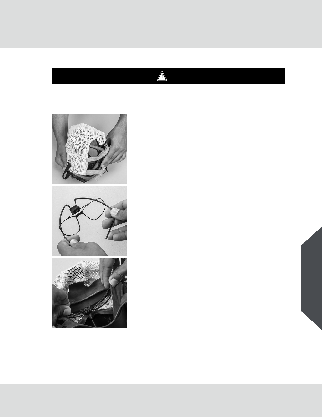
WARNING
Before using a spectacle kit, an optometrist must inspect the spectacle kit and prescribe the correct
lenses to fit into the lens frame on the spectacle kit. Failure to follow this warning could result in
serious personal injury or death.
(1) Flip the head harness over the front of the facepiece so the
harness is covering the lens of the facepiece.
This will open up the faceblank to make it easier to install
the spectacle kit.
(2) Squeeze in on the wire frame of the spectacle kit at the
large bends about 2" from the ends.
(3) Push the top part of the frame into the lens. The faceblank
has three rubber tabs to grab the frame.
Place the frame in the middle of the lens with the smaller
tabs grabbing the wire frame.

85
Spectacle Kit
G1
US
(4) Take one end of the wire frame and push it up into the face-
piece so it follows the edge where the lens and the face-
blank meet.
The end of the wire frame must be positioned into small
pockets in the faceblank on the edge of the lens.
(5) Repeat step (4) on the opposite side.
(6) The lens frame can be adjusted up/down and in/out
depending on the facial features. Don the facepiece and
adjust to optimize visibility.

86
Telemetry Module
G1
US
18 Telemetry Module
The telemetry module is designed to allow the SCBA to communicate with a remote base station while
in use. The SCBA with telemetry module installed will transmit vital statistics such as cylinder pres-
sure, thermal alarm (if thermal alarm is enabled), service time remaining, and PASS alarm to the base
station. The base station also has the ability to send an evacuation command to the SCBA. The telem-
etry module uses a special version of the power module.
All basic functions of the SCBA are the same as those described in the During Use section of this
manual except for the following differences:
-Turning the control module ON: When the control module is activated in the presence of a
remote base station, the SCBA automatically begins to log on to that base station. When the SCBA
is successfully logged on to the base station, a radio link indicator will appear on the display of the
control module.
-Evacuation Signal: The SCBA has the ability to receive an evacuation signal from the remote
base station after it has been successfully logged on to the base station. When an evacuation
signal has been sent by the base station, the “running man” icon will appear, and flash, on the
display of control module and a unique audible alarm will be emitted from the power module. The
evacuation signal must be manually confirmed by the user by pressing the reset button (green)
twice within approximately one second. This confirms the evacuation signal by sending a confir-
mation signal back to the base station. Once the evacuation signal has been manually confirmed
by the user, the “running man” icon will stop flashing and remain on the display until the control
module has been turned off.
-PASS Alarm: The PASS alarm will sound and function normally with the telemetry module. When
the SCBA emits a full PASS alarm, a signal is automatically sent to the base station to alert Incident
Command.
-Thermal Alarm: When the SCBA is exposed to temperature conditions that warrant a thermal
alarm, a signal is automatically sent to the base station to alert Incident Command.
-Low Battery: When the power module reaches a low battery condition, a signal is automatically
sent to the base station to alert Incident Command.
-Data Log: The data logging feature of the control module logs the status of the radio link to the
base station as well as any evacuation signals that the SCBA has received.
-Radio Link Indicator: The control module has a radio link indicator on the secondary screen.
When this icon is displayed, the SCBA is logged on to a base station and within range. When the
radio link indicator is red, it means the radio contact has been lost or interrupted. When the radio
link indicator is grey, it means the radio contact was never established.
-Turning the control module Off: To turn the control module off, press the reset button (green)
twice within approximately one second. If the SCBA is logged on to the base station, there will be
a delay between the two presses of the reset button and the actual shutdown of the device. Before
the control module completely turns off, the base station must remove the SCBA from its registry.
This causes the slight delay between pressing the reset button and the actual shutdown of the
device.
87
Telemetry Module
G1
US
Scanning the ID Tag into the Power Module
Prior to pressurization of the SCBA and during use, the user can “tag in” to the SCBA. The most recent
ID Tag data that is stored in the power module will be used as the identification for the SCBA in the
data log or on the MSA Accountability System Software. If no ID Tag data has been assigned to the
SCBA, the power module serial number will be used as its identification on the base station PC
screen.
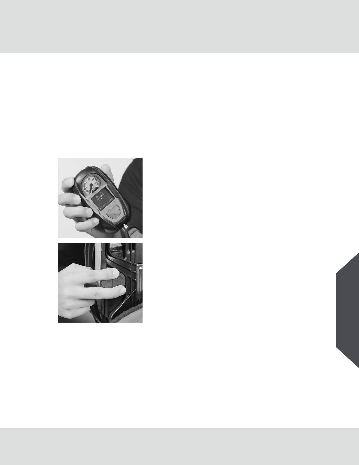
Tagging In when Unit is Off
(1) Take the ID tag and place in hand as shown.
(2) Move hand to the RFID reader location on the power
module. It is located on the user side of the backplate on
the left side.
(3) Press and hold the green reset button until the RFID
symbol appears.
(4) Keep the tag located at the power module until the blue
bar moves across the screen.
If the tag was successful, the information will be
displayed on the tag. If it is not, repeat the steps above
until the tag information is displayed on the screen.
88
Telemetry Module
G1
US
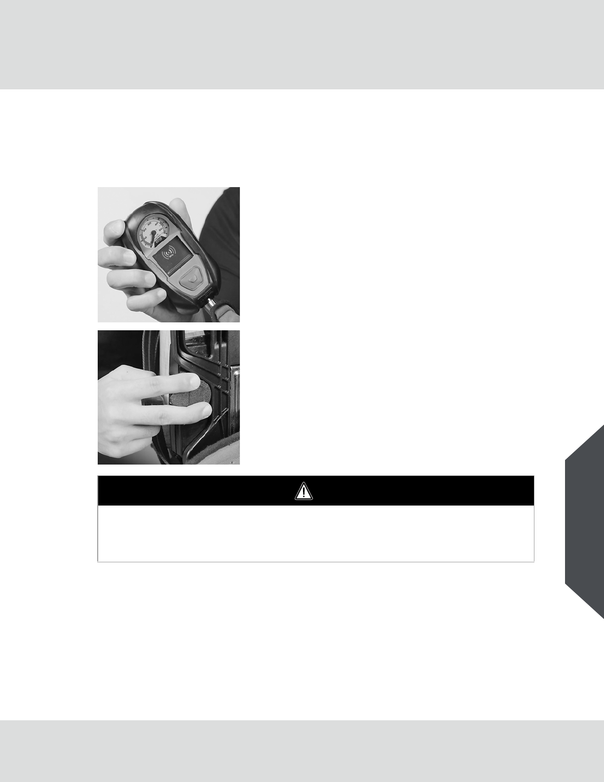
Tagging In During Use
Using the Base Station with the Telemetry Module
The telemetry module is designed to work in conjunction with a remote base station unit. This base
station unit must be connected to a personal computer or notebook computer before use. Refer to the
MSA A2 Software Instructions (P/N 10162374) for more information.
(1) Take the ID tag and place in hand.
(2) Move hand to the RFID reader location on the power
module. It is located on the user side of the backplate on
the left side.
(3) Press and hold the green reset button until the RFID
symbol appears.
(4) Keep the tag located at the power module until the blue bar
moves across the screen.
If the tag was successful, the information will be
displayed on the tag. If it is not, repeat the steps above
until the tag information is displayed on the screen.
WARNING
When using an ID Tag with the G1 power module, the ID Tag must touching the power module during
this process. If the tag is not, the PASS device can lockup. To fix the lockup, the batteries must be
removed for 30 seconds and then reinstalled.
Misuse can result in serious injury or death.
89
Telemetry Module
G1
US
18.1 Using the SCBA with Telemetry Module
Logging the SCBA on to the Base Station
(1) Turn on the control module on by opening the cylinder valve or by pressing and holding the alarm
button.
(2) An icon representing the user of the SCBA will appear on the base station PC screen.
(3) When the base station has established contact with the SCBA and all initial information has been
obtained, the radio link indicator will appear in the upper left corner of the control module display.
(4) Periodically check the status of the radio link indicator on the display of the control module. If the
signal indicator turns yellow, this means that the SCBA is out of range from the base station. The
signal strength indicator will stop flashing when the SCBA returns within range of the base
station.
Logging the SCBA off of the Base Station
(1) Once the user has returned to fresh air the control module may be turned off.
(2) Close the cylinder valve and purge the remaining air from the system using the regulator bypass.
When the pressure falls below 200 psi, turn the control module off (sleep mode) by pressing the
reset button twice in approximately one second. (When the SCBA is logged on to a base station,
there may be a delay between the two rapid presses of the reset button and the actual shutdown
of the control module. Before the control module completely turns off, the base station must log
off the SCBA and send out a final confirmation signal.
Evacuation Signal
If the SCBA is logged on to the base station, the incident command will have the ability to send an
evacuation signal to the SCBA. When an evacuation signal is sent to the SCBA, the power module
will begin to beep repeatedly and a flashing evacuation icon will appear on the control module display.
The evacuation alarm will continue to sound until the reset button on the control module has been
pressed twice within approximately one second. This confirms the evacuation by sending a confirma-
tion signal back to the base station. The evacuation alarm can only be reset on the SCBA after the
unit has been turned off and restarted.
WARNING
Follow the PC or notebook computer manufacturer's recommendations for exposure to environ-
mental conditions to prevent damage to the system.
Failure to do so may cause system failure and the loss of monitoring capability on the PC or note-
book computer.
CAUTION
If the signal strength indicator does not appear on the control module display or the base station has
not logged the unit on, the base station cannot monitor the status of that user.
90
Maintenance
G1
US
19 Maintenance
19.1 Batteries
WARNING
-Replace the batteries following the use of the SCBA were the low battery alarm became active.
-Changing of alkaline batteries must be performed in a non-hazardous environment.
-Battery modules must only be removed and installed in a non-hazardous environment.
-Use only approved batteries in the battery module.
-Use of other batteries, or a combination of batteries from different manufacturers, will affect the
performance of the unit and void the Intrinsic Safety Approval.
Failure to follow this warning could result in serious injury or death.
WARNING
DO NOT dispose of the batteries in fire. They may explode. Contact the local municipality for proper
disposal of batteries.
Misuse can result in serious injury or death.
WARNING
Use only approved alkaline batteries in the battery module. Use of other batteries, or a combination
of batteries from different manufacturers, will affect the performance of unit and void the Intrinsic
Safety Approval.
CAUTION
Do not use force to remove or replace the battery pack, otherwise the power module could get
damaged.
Battery status can be checked while the SCBA is still in the jump seat, the battery pack can
also be replaced without taking the SCBA out of the jumpseat.

91
Maintenance
G1
US
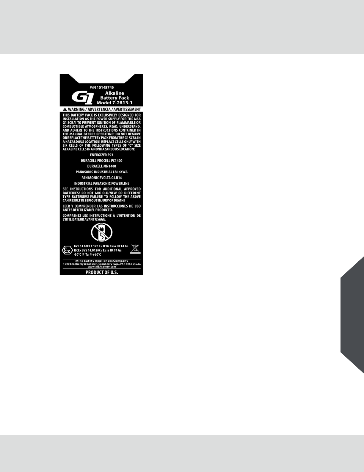
List of approved batteries that can be used in the alkaline battery pack
-Duracell Procell PC1400
-Duracell MN1400
-Panasonic Evolta C-LR14
-Panasonic Industrial LR14XWA
-Industrial Panasonic Powerline
-Rayovac Ultra Pro LR14
-Rayovac LR14
-Energizer EN93
-Energizer E93
NOTE: The temperature class is T4 when the above alkaline cells are installed within the alkaline
battery pack, except the temperature class is T3C when the Energizer EN93 alkaline cells are
installed within the alkaline battery pack.
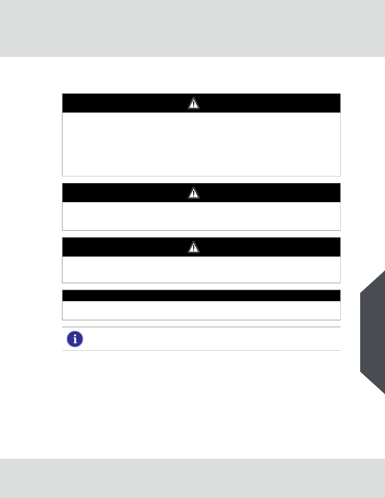
Replacing the Batteries in the Battery Module
The battery module is installed on the user side of the SCBA in the middle of the backplate.
(1) Unlock the battery module with the battery removal tool.
Push the removal tool into the slot in the battery module
and click into place.
Pull the removal tool and the battery module out of the
power module.
Open the battery module:
(2) Loosen the Torx screws in the battery housing lid.
92
Maintenance
G1
US
(3) Remove the battery housing lid.
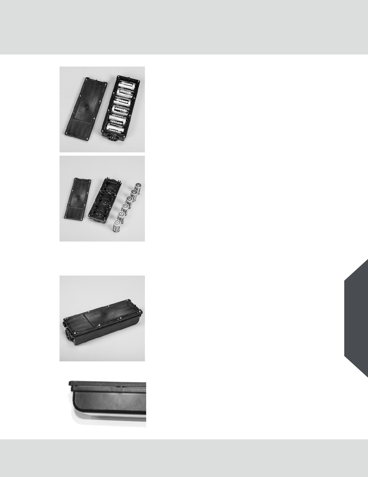
(4) Remove all 6 batteries.
(5) Check the inside of the battery module for damage, battery
acid, corrosion, dirt and debris.
(6) Ensure the battery contacts are in place and secure.
(7) Insert 6 fresh C-cell batteries, ensuring the + contacts are in
alignment.
(8) Check the cover of the battery module for damage, dirt and
debris, make sure the gasket is still in place and does not
have any nicks or tears.
Replace cover if necessary.
Close battery module:
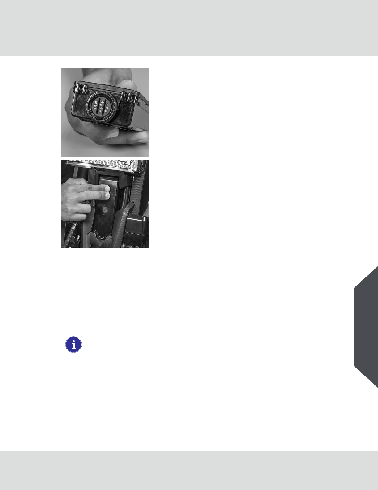
(9) Place the battery lid on the housing and install the screws
until the lid makes contact with the standoffs
(4 in-lbs max torque).
NOTE: This is the position of the battery lid to the housing once the
screws are tightened.
93
Maintenance
G1
US
19.2 Maintenance Instructions
This product should be regularly checked and serviced by trained specialists. Inspection and service
records must be maintained. Always use original parts from MSA.
Repairs and maintenance must be carried out only by authorized service centers or by MSA. Changes
to devices or components are not permitted and will result in an unapproved configuration.
MSA is liable only for maintenance and repairs carried out by MSA.
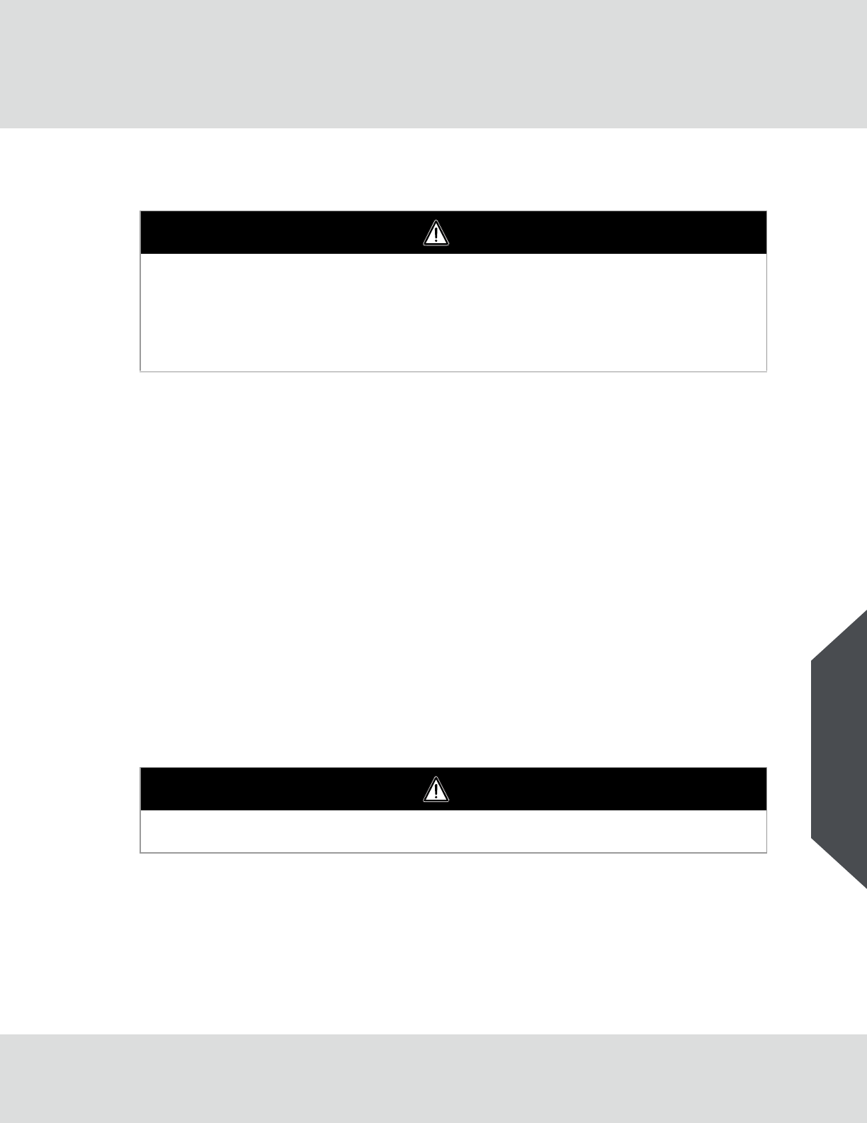
Install the battery module in the power module:
(10) Make sure before inserting the battery pack that the power
module is clean and that no pins or grooves are damaged.
(11) Insert the battery pack into the power module, ensure to align
it with the grooves in the power module.
Release the battery module and push in its top.
The battery module will click into place.
(12) To make sure that the battery pack fits securely, push on the
opposite side of the power module, the battery pack should
not move.
MSA recommends maintenance intervals which follow the overhaul and flow test require-
ments.
Observe national laws and regulations!
If in any doubt, ask your local MSA contact person.
94
Safekeeping and Storage
G1
US
20 Safekeeping and Storage
20.1 Storage
-Do not store the SCBA or spare cylinders within or near an area where the SCBA can or might be
exposed to any substances that will or might attack any part of the SCBA, causing the SCBA to
not perform as designed and approved.
-Prior to storing the SCBA in a jumpseat, ensure there is no interference between the SCBA and
the seat. Ensure the SCBA and cylinder can be removed easily without damaging the components.
-Do not store the SCBA for extended periods with the batteries installed in the electronic compo-
nents if the SCBA is not intended for service. If the SCBA is in service, ensure that the batteries in
the electronic components have an adequate charge.
-Do not store the SCBA with an empty or partially filled cylinder. Always install a fully-charged
cylinder so that the SCBA is ready for use.
-Complete Inspection and Cleaning and Disinfecting Procedures outlined in this manual. Ensure
the entire SCBA is clean and dry.
-Ensure the facepiece head harness adjustment straps are fully extended. Place the complete
SCBA in the storage case or suitable storage location so it can be easily reached for emergency
use.
-For prolonged storage of the SCBA, remove the batteries from all electronic components and
housings to prevent battery corrosion. Store the units in a cool, dry place.
NOTE: Fresh batteries must be installed in the power module prior to storage of the SCBA at cold
temperature for an extended period of time.
20.2 Facepiece
For the safekeeping of the facepiece, a facepiece pouch or container should be used.
MSA rubber products are protected by an anti-ageing agent that can become visible as a light coating.
This coating is harmless and can be removed.
To ensure a long life of rubber components, follow ISO 2230 by storing them in a cool, dry place
protected from ultraviolet radiation.
WARNING
-Prior to storage of the SCBA at temperatures below 0°F (-18°C), verify that the power module is
equipped with full charge batteries. Verify that the control module displays a full charge battery
status icon and that the HUD does not display low battery status indicators.
-DO NOT drop the cylinder or bump the valve knob. An unsecured cylinder can become an
airborne projectile under its own pressure if the valve is opened even slightly.
Misuse can result in serious injury or death.
WARNING
In order to avoid damage to or the deformation of the facepieces keep no additional loose objects in
the facepiece container. Failure to follow this warning can result in serious injury or death.
95
Product Labels
G1
US
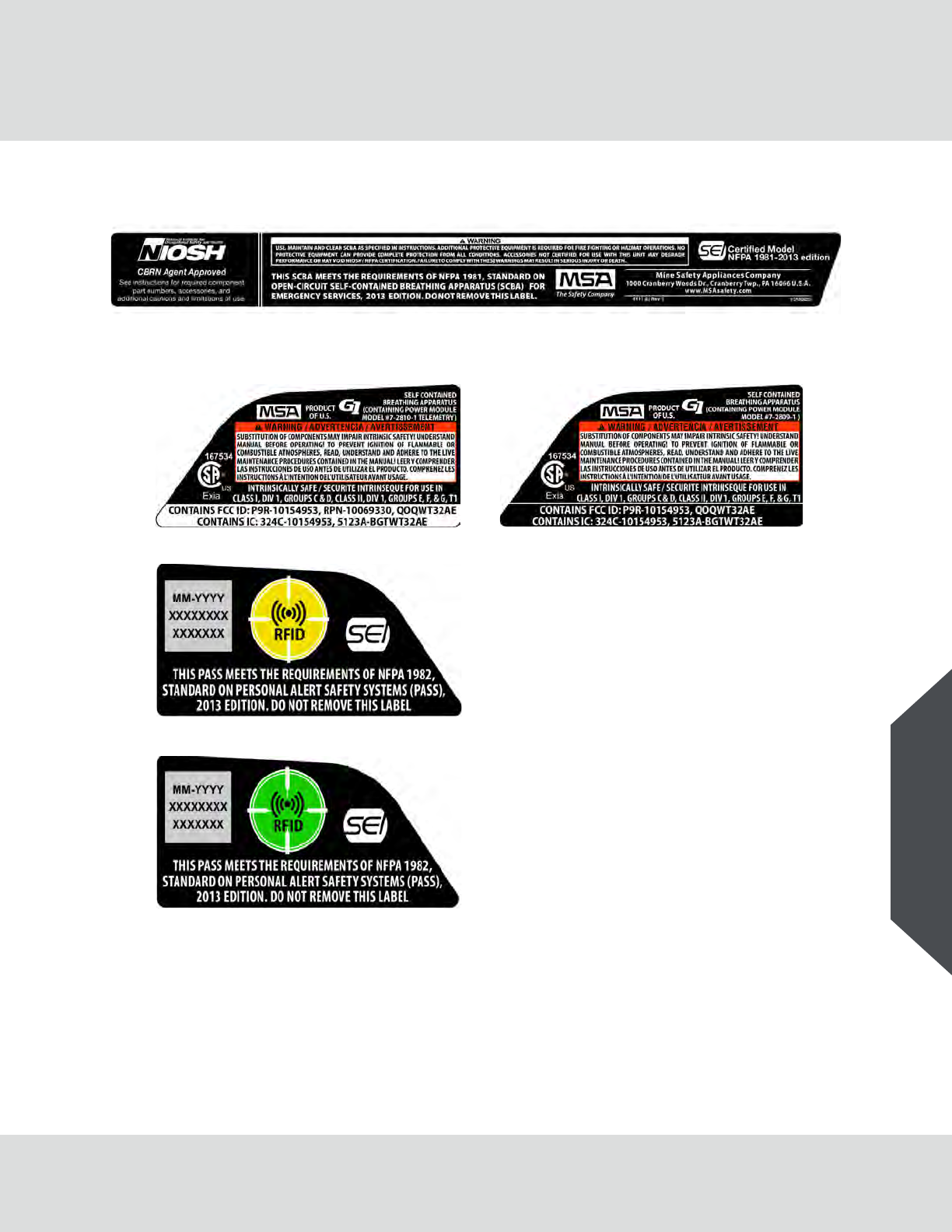
21 Product Labels
NFPA 1981 (SCBA)/CBRN
NFPA 1982 (PASS)/INTRINSIC SAFETY/FCC (Power Module)
2216 Pressure
4500 Pressure
With Telemetry Without Telemetry

96
Product Labels
G1
US
Facepiece
G1 Tag
User Removable PASS Warning (Battery Pack)
97
Product Labels
G1
US
Battery pack

98
MSA G1 SCBA Limited Warranty
G1
US
22 MSA G1 SCBA Limited Warranty
MSA - The Safety Company (MSA) warrants MSA G1 SCBA (SCBA) to be free from defects in mate-
rials and/or faulty workmanship for a period of fifteen (15) years from the date of sale by MSA. This
warranty applies to all components of the SCBA including all accessories and optional equipment
purchased and supplied at the time of the original sale of the SCBA, except consumable parts, as
defined by the terms of sale. MSA’s obligation under this warranty is limited to the repair or replace-
ment, at MSA’s option, of the SCBA or components shown to be defective in either workmanship or
materials.
No agent, employee or representative of MSA may bind MSA to any affirmation, representation or
modification of the warranty concerning the goods sold under this contract. MSA makes no warranty
concerning components or accessories not manufactured by MSA, but will pass on to the Purchaser
all warranties of manufacturers of such components.
MSA shall be released from all obligations under this warranty in the event that repairs or modifica-
tions are made by persons other than its own or authorized service personnel, or if the warranty claim
results from accident, alteration, misuse, or abuse.
THIS WARRANTY IS IN LIEU OF ALL OTHER WARRANTEES, EXPRESSED, IMPLIED, OR
STATUTORY INCLUDING, BUT NOT LIMITED TO, ANY IMPLIED WARRANTY OF MERCHANT-
ABILITY OR FITNESS FOR A PARTICULAR PURPOSE. IN ADDITION, MSA EXPRESSLY
DISCLAIMS ANY LIABILITY FOR ECONOMIC, SPECIAL, INCIDENTAL, OR CONSEQUENTIAL
DAMAGES IN ANY WAY CONNECTED WITH THE SALE OR USE OF MSA PRODUCTS,
INCLUDING, BUT NOT LIMITED TO, LOSS OF ANTICIPATED PROFITS.

Because every life has a purpose...
For local MSA contacts, please visit us at MSAsafety.com