Minelab Electronics 1010 METAL DETECTOR FOR RECREATIONAL USE User Manual
Minelab Electronics Pty Ltd METAL DETECTOR FOR RECREATIONAL USE Users Manual
Users Manual

1
Metal detecting is a fascinating and
rewarding activity enjoyed by people
all over the world. By getting to know
your CTX 3030 you can become one of
the many successful detectorists who
combine their passion for the outdoors
with the excitement of discovering
valuable coins, relics, gold and jewellery
on a regular basis.
CTX 3030 is Minelab’s most
technologically advanced detector,
incorporating the unique Full Band
Spectrum 2 (FBS 2) Technology. Its sleek,
sturdy design, innovative control panel,
clear LCD, robust lightweight coil and
comprehensive targeting options set it
apart from any other detector available
today. The Wireless Audio Receiver
Module (WARM) facilitates the use of
wireless speaker or headphones.
Congratulations on purchasing
your Minelab
metal detector!
CTX 3030 also allows you to download
and upload CTX 3030 settings, User
Modes and Discrimination Patterns using
your own Personal Computer (PC).
CTX 3030 will locate valuable metal
objects in a variety of mineralized ground
conditions, including extremely salty
soils, sea water, wet beach sand and
highly magnetic ground conditions. New
functionality allows you to customise your
CTX 3030 to your specic requirements.
This manual is designed to help both
the beginner and expert treasure hunter
obtain the best performance with their
CTX 3030.
Minelab wishes you every success with
your CTX 3030!

2Contents
Item Number: 4901-xxxx
Revision: 0.1
Contents ................................................................................................2
Detector Parts .......................................................................................4
Assembly ...............................................................................................5
Attach the Coil to the Lower Shaft ....................................................................5
Attach the Lower Shaft to the Chassis .............................................................6
Attach the Control Box ...........................................................................................6
Attach the Armrest ...................................................................................................7
Attach the Headphones .........................................................................................7
Disconnect the Coil ..................................................................................................7
Adjust the Detector for Comfortable Detecting ............................8
Holding the Detector ..............................................................................................8
Adjust the Armrest Strap........................................................................................8
Adjust the Position of the Armrest .....................................................................8
Adjust the Length of the Shafts ..........................................................................9
Adjust the Angle of the Coil ..............................................................................10
Battery Packs ..................................................................................... 11
Insert the Battery Pack into the Battery Compartment .........................11
Remove the Battery Pack from the Battery Compartment ..................12
Recharge the Li-Ion Battery Pack with the BC 10 Battery Charger ...12
Recharge the Li-ion Battery Pack with the Car Charger ........................13
Replace the ‘AA’ Batteries .................................................................................... 14
Turn On and Go ................................................................................. 15
Power Button ...........................................................................................................15
Compliance Information .................................................................. 16
Information to the User
(FCC Part 15.105) ................................................................................................... 16
3
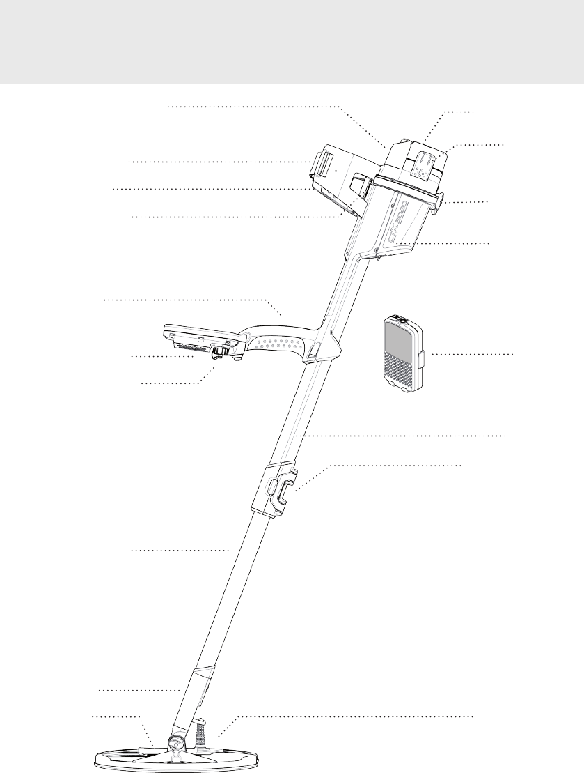
Detector Parts
Headphones Module
Velcro Strap
Armrest
Armrest Lock
Handle
Control Pod
USB Connector
Lower Shaft
Yoke
Coil
Battery Cover/
Compartment
Latches
Control Box
Bulkhead
Control Box
WARM
Chassis
Chassis Cam Lock
Coil Connector
4
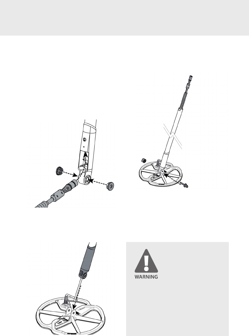
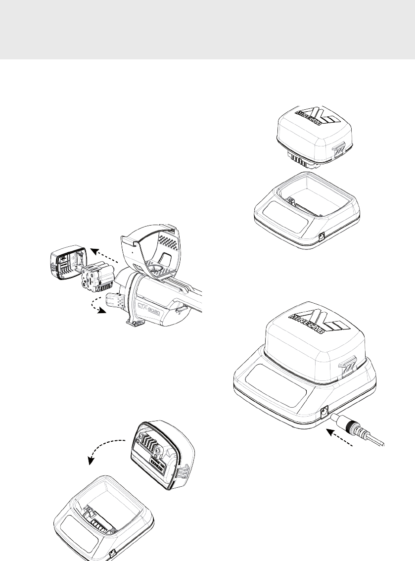
Attach the Coil to the Lower Shaft
1. Remove the nut, bolt and washers from
the coil.
2. Plug the two rubber washers into the
holes on either side of the lower shaft.
3. Feed the coil cable up through the inside
of the lower shaft until it appears at the
top of the lower shaft.
4. Place the coil on a at surface and slide
the lower shaft into the bracket on top of
the coil. Ensure that the open side of the
lower shaft faces the ground.
Assembly
5. Insert the bolt through the lower shaft
and the bracket on top of the coil.
6. Fasten with the nut provided, taking
care not to damage the thread of the
nut by over-tightening. This will need to
be loosened later to adjust the coil to a
comfortable detecting angle (x-ref ).
PINCH POINTS - CONTROL BOX. Take
care when sliding the control box onto
the chassis and when operating the
control box clip.
The coil cable is directly wired into the
coil and is not removable.
5
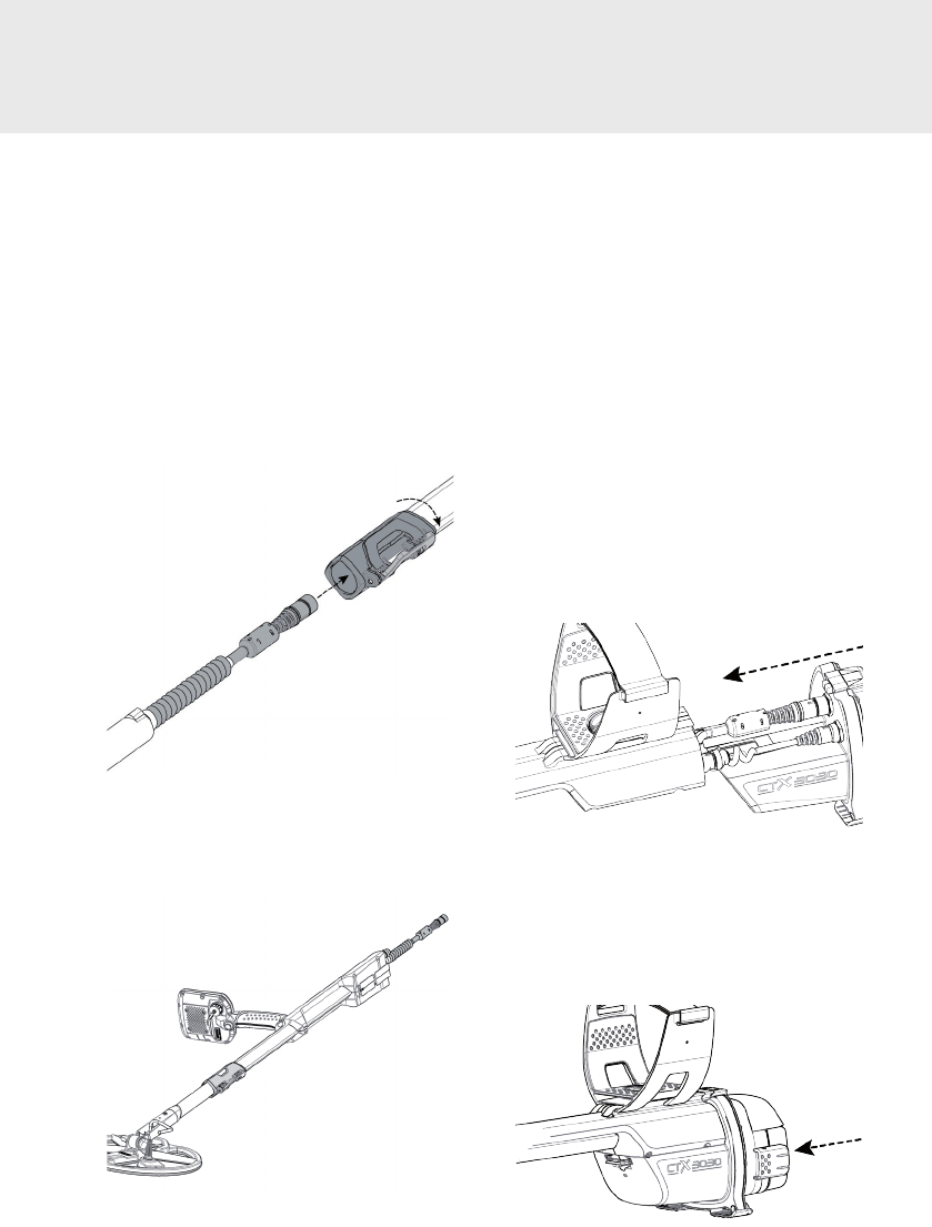
Attach the Lower Shaft to the
Chassis
1. Release the chassis cam lock by pulling
the lever away from the shaft.
2. Feed the coil cable up through the inside
of the chassis ensuring the cam lock side
of the shaft is facing the ground and that
the key stop on the lower shaft is rotated
90° to the chassis.
3. Slide the chassis over the lower shaft
until the coil cable and key stop appear
at the top. Rotate the lower shaft 90°
so that the key stop points downwards.
4. Lock the chassis cam lock by pushing the
lever towards the shaft
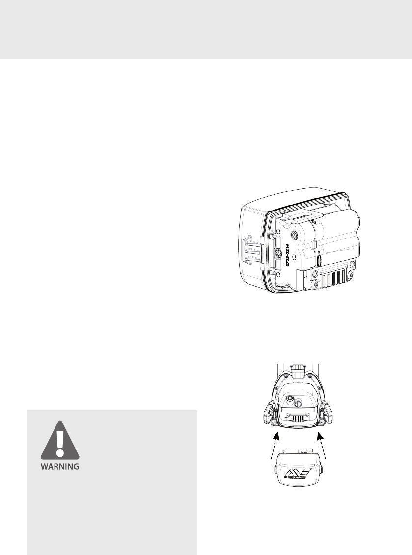
Attach the Control Box
1. Ensure the latches on the control box are
released and place the battery pack into
the cover. Position the battery cover onto
the control box and lock the latches to
secure.
2. Fit the headphone module onto the
control box. Use a screwdriver or coin
to tighten the bolt taking care not to
damage the thread by over-tightening.
3. Slide the control box partly onto the
chassis. Attach the coil cable and user
interface (UI) cable to their respective
connectors, and rmly tighten the
retaining rings.
4. Slide the control box further along the
chassis until it locks into place. Beware of
pinch points when sliding the control box
into place.
6
Attach the Armrest
1. Thread the Velcro strap through the
armrest, with the Velcro side facing up.
2. Slide the armrest onto the rail on top of
the chassis. Ensure that the sloping sides
of the armrest face toward the control
panel.
3. Turn the armrest lock clockwise to fasten
the armrest in the desired position.
NOTE
To t a smaller arm, the Velcro strap can be
tted upside down and passed through the
armrest three times.
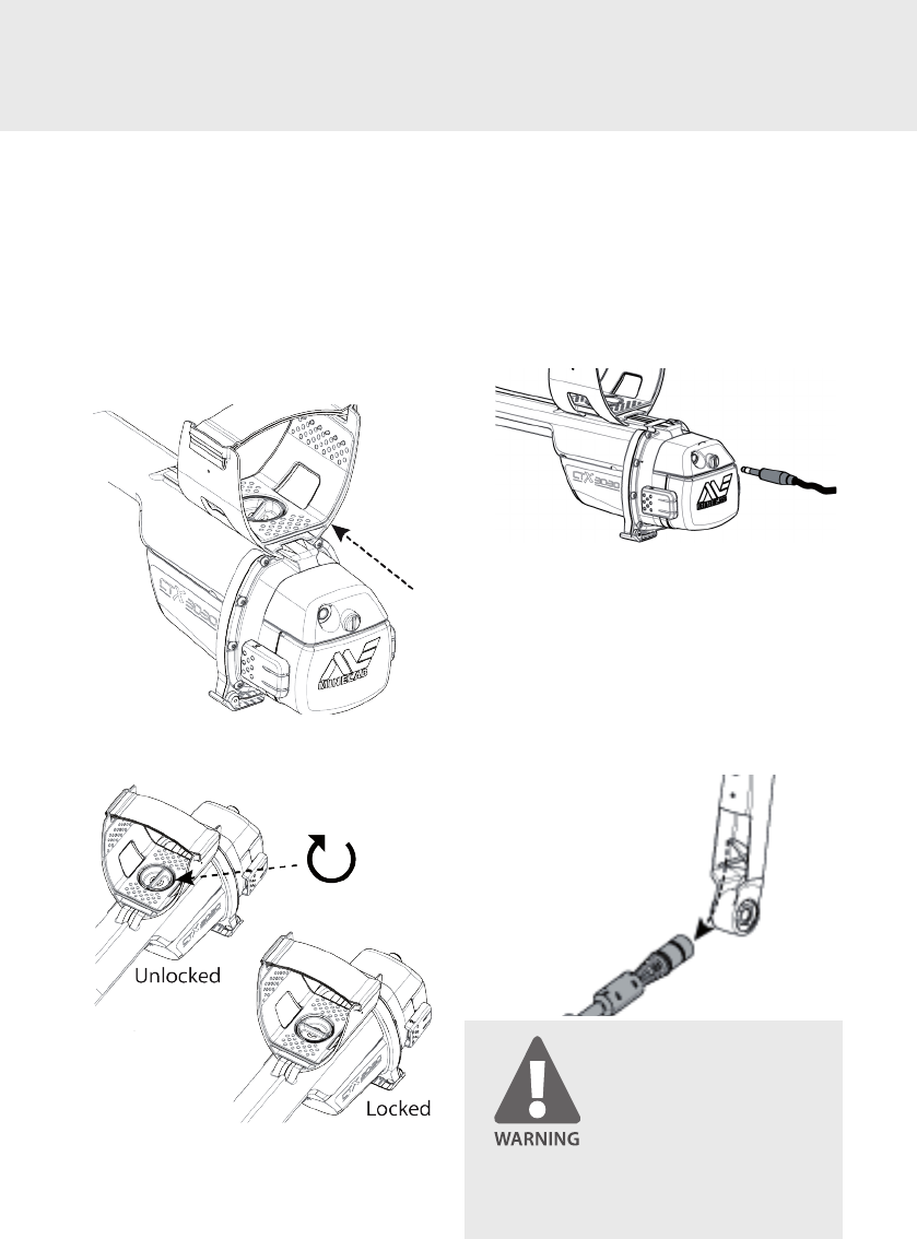
Attach the Headphones
1. Plug the headphone jack into the
headphone module located above the
battery compartment. The headphones
may be plugged or unplugged at any
time.
Disconnect the Coil
1. Reverse the steps in ‘Attach the Control
Box’, ‘Attach the Lower Shaft to the
Chassis’ and ‘Attach the Coil to the Lower
Shaft’.
2. Pull the coil cable out from inside the
lower shaft.
Do not attempt to completely remove
the shaft assembly while the coil cable is
still connected to the control box.
7
Adjust the Detector for
Comfortable Detecting
For comfortable detecting it is important
to take the time to adjust the detector
correctly.
Holding the Detector
Thread your arm through the armrest and
strap. Grasp the handle of the detector
and rest your forearm in the armrest.
The correct position of the armrest should
allow you to comfortably grip the handle.
Your elbow should sit just above the back
of the armrest and the detector should
feel like an extension of your forearm.
Adjust the Armrest Strap
1. Loosen the Velcro strap by lifting the top
edge.
2. Tighten the strap until your arm is secure
in the armrest.
3. Re-attach the Velcro.
Adjust the Position of the Armrest
1. Turn the armrest lock counter-clockwise
to realease the armrest.
2. Hold the detector and slide the armrest
up or down the rail until it is positioned
just below your elbow.
3. Remove your arm from and turn the
armrest lock clockwise to lock it into
position.
8
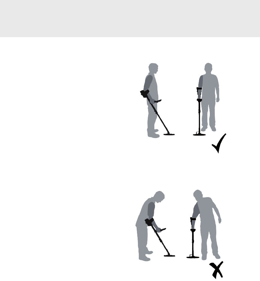
Adjust the Length of the Shafts
The lower shaft can be adjusted to any
length between fully extended and fully
retracted.
1. Adjust the lower shaft to the correct
length and secure the cam lock to hold it
in place.
A correct shaft length will allow you to
swing the coil over the ground without
uncomfortably stretching or stooping.
If the coil is too far from your body it will
be dicult to balance and manoeuvre
while detecting.
If the coil is too close to your body it may
detect your digging tools or any other
metal which you are carrying, causing
confusing sounds.
Shaft is the correct
length
Shaft is too short
9
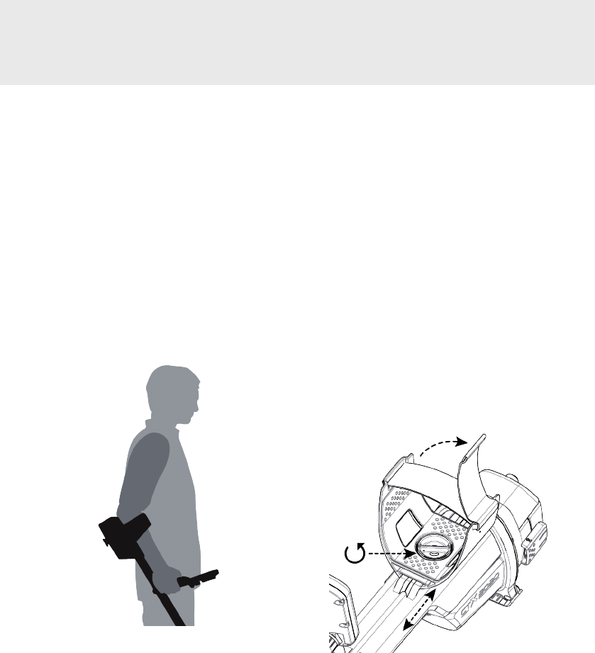
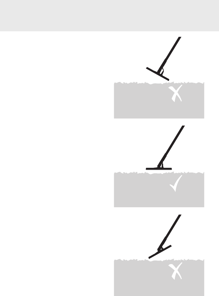
Adjust the Angle of the Coil
1. Loosen the bolt that connects the lower
shaft to the coil. It should be loose
enough to allow the coil to be moved for
adjustment, but tight enough that the
coil can hold its position.
2. While holding the detector as if detecting,
lightly press the coil to the ground until it
sits at/parallel with the ground. The coil
should remain parallel when lifting to the
sweep height, approximately 25mm (1”)
above the ground.
3. Tighten the bolt, taking care not over-
tighten it.
10
The CTX 3030 is supplied with two types
of battery pack:
1. A replaceable cell pack, which accepts
eight AA batteries including alkaline
and rechargeable NiCd or NiMH
batteries. The batteries are packed
into a cage, which is inserted into
the battery cover. The detector will
operate for a minimum of seven hours
using an alkaline battery pack.
2. A sealed rechargeable Li-Ion smart
battery, which comes with a charger
that plugs into a conventional wall
socket. This battery pack is supplied
discharged and needs to be charged
for 18 hours before operating the
detector. The detector will operate for
a minimum of eight hours using the
Li-Ion battery pack.
NOTE
Since there may be a variety of options
available for this detector, equipment
may vary according to the model or
items ordered with your detector. Certain
descriptions and illustrations may also dier
(in this manual) from the exact model you
purchased.
Battery Packs
Insert the Battery Pack into the
Battery Compartment
1. Ensure latches on the control box
bulkhead are released and clear of the
battery slot.
2. Insert the battery pack into the battery
cover.
3. Gently push the battery cover onto
the control box bulkhead and close
the latches to secure the battery
compartment.
NOTE
Batteries are NOT waterproof except when
fully attached to the detector.
Do not attempt to disassemble the NiMH
or Li-ion battery packs.
If disposing of battery pack, do not
incinerate. Contact your local authorities
to enquire about disposal or recycling
facilities.
11
Remove the Battery Pack from the
Battery Compartment
1. Ensure that the detector is turned o
before removing the battery pack.
2. Rest the detector on a at surface and
release the latches on both sides of the
control box.
3. Remove the battery pack from the control
box bulkhead.
Recharge the Li-Ion Battery Pack
with the BC 10 Battery Charger
1. Remove the battery pack from the
detector (x-ref ) and place it into the
charger unit, ensuring that the pins line
up.
2. Insert the plug pack cable connector into
the socket on the right hand side of the
charger unit.
3. Plug the other end of the cable into the
wall socket and turn on the switch. (see
BX 10 instruction manual?).
4. Leave the unit for 18 hours to fully
recharge.
If the battery was not completely
discharged, the charging time will be
shorter. New batteries will reach their full

12
small light on the car charger illuminates
indicating that the car charger is in
operation.
4. Leave for 18 hours to fully recharge. If the
battery was not completely discharged,
the charging time will be shorter.
5. Some vehicles may require the ignition to
be switched on to ‘Accessories’ for power
to be supplied to the charger.
6. Charging the battery for longer than 18
hours will not damage the Li-ion battery
pack. However, it may gradually discharge
your car battery.
NOTE
The car charger is provided with a fuse
for short circuit protection. The fuse can
be accessed by unscrewing the tip of the
charger plug.
capacity after several charge/discharge
cycles.
5. Once charged, disconnect the plug pack
and remove the battery pack from the
charger.
NOTE
For best results, the battery pack must be
recharged whenever the detector has been
unused for a long period of time.
Recharge the Li-ion Battery Pack
with the Car Charger
1. Remove the battery pack.
2. Insert the car charger plug into the
accessories socket of your vehicle.
3. Insert the car charger plug into the socket
at the tapered end of the battery pack. A
The Lithium-ion battery is specically
designed for the CTX 3030 and is
not compatible with non-CTX 3030
detectors. Attempting to use the
Lithium-ion battery pack with other
detectors may damage the detector or
the battery pack. Do not try to adapt
this battery to other models as it will
very likely cause damage.
Do not charge the battery at
temperatures above 45°C (113°F) or
below 0°C (32°F).
Do not immerse the battery in any
liquid or allow water ingress.
Do not leave the battery in hot
conditions (e.g. on the dashboard of
your car or rear parcel shelf ).
Do not throw the battery or impact it in
any way.
Do not short-circuit the battery.
Do not use the battery if it is damaged
or deformed.
Do not disassemble or reconstruct the
battery.
Do not incinerate the battery.
In the event of a fault, return the battery
to a Minelab authorised service centre
for repair. The use of non-approved
components will VOID YOUR WARRANTY.
There are no user serviceable parts
within this battery pack.

13
Replace the ‘AA’ Batteries
1. Remove the battery pack from the battery
compartment (x-ref ).
2. Remove the used batteries from the
battery pack.
3. Place 8 x ‘AA’ cell alkaline batteries into
the battery pack ensuring that the + and
– terminals are aligned as indicated on
the label.
4. Insert the battery pack into the battery
compartment and close the latches to
secure the battery cover (x-ref ).
High quality alkaline batteries are
recommended for optimum detection
time. Rechargeable alkaline, NiMH or
NiCad batteries may be used but must be
removed and recharged separately. Check
tment of rechargeable batteries prior to
purchase, as some do not comply with
standard size requirements.
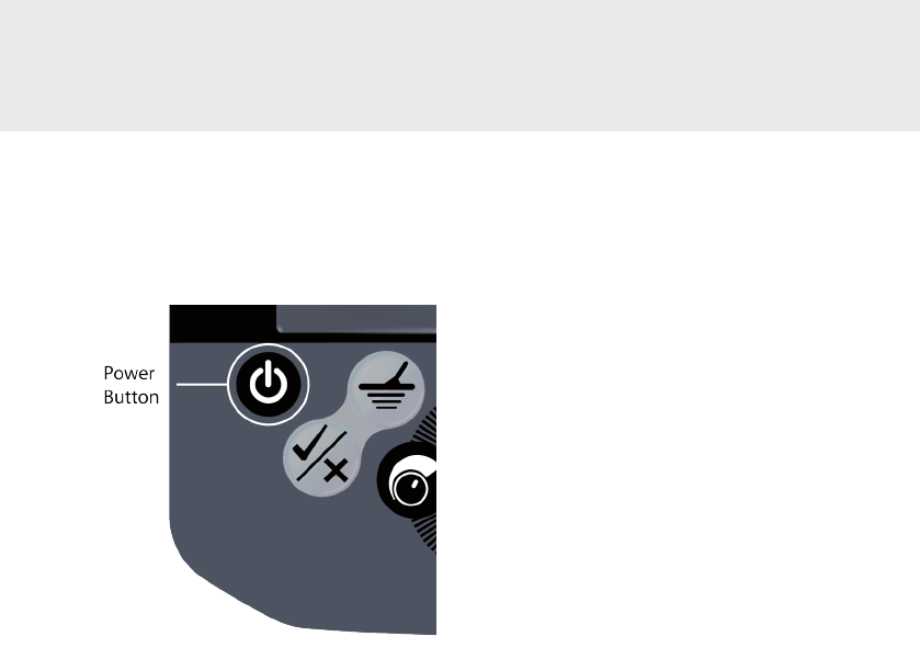
14 Turn On and Go
Power Button
Short Press: On/O
Long Press: Factory Preset
Press the Power button once to turn the
detector on.
The detector will begin with an animation
and tune, after which the Smartnd
Detect screen will appear and CTX 3030 is
ready to nd treasure!
NOTE
On initial startup only, the detector will
begin with an animation and tune, after
which you will be prompted to select your
preferred language before proceeding to the
Smartnd Detect screen.
It is best to operate the detector only
when outdoors and away from sources
of electromagnetic interference (EMI)
such as power lines and phone towers.
These sources may cause the detector to
perform erratically, giving false signals and
causing inaccurate target ID.
There are also many metallic objects
inside a house, such as nails in the oor,
reinforcing in the walls, televisions and
other household appliances, that might
overload the electronics of the detector.
Overloading is not harmful to the
electronics of the detector. CTX 3030 is
designed to withstand coil overload.
NOTE
Sometimes it is possible that a large object
close to the coil will overload the detector’s
electronics. When this happens, CTX 3030
displays an Overload message and emits a
fading Overload sound which repeats until
the coil is moved away from the source of
the overload.
Each time you turn the detector on, the
last detection screen used before shutting
down will appear. For example, if CTX
3030 was operating in the Smartnd
Detect screen when turned o, this screen
will appear when CTX 3030 is turned back
on.
Press the power button to turn the
detector o.

15
Compliance Information
Information to the User
(FCC Part 15.105)
NOTE Class B Devices
This equipment has been tested and
found to comply with the limits for a Class
B digital device, pursuant to part 15 of
the FCC Rules. These limits are designed
to provide reasonable protection against
harmful interference in a residential
installation.
This equipment generates, uses and can
radiate radio frequency energy and, if
not installed and used in accordance
with the instructions, may cause harmful
interference to radio communications.
However, there is no guarantee that
interference will not occur in a particular
installation. If this equipment does cause
harmful interference to radio or television
reception, which can be determined
by turning the equipment of and on,
the user is encouraged to try to correct
the interference by one or more of the
following measures:
•Reorient or relocate the receiving
antenna
•Increase the separation between the
equipment and receiver
•Connect the equipment into an outlet
on a circuit dierent from that to
which the receiver is connected
•Consult the dealer or an experienced
radio/TV technician for help
Any changes or modications not
expressively approved by Minelab
Electronics Pty Ltd could void the user’s
authority to operate this equipment.