Minelab Electronics 7000 Metal Detector for recreational use User Manual
Minelab Electronics Pty Ltd Metal Detector for recreational use Users Manual
UserManual.wiki
>
Minelab Electronics
>
7000 User Manual
>
Users Manual
Contents
1.
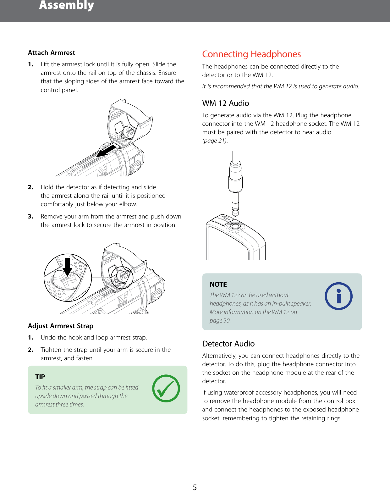
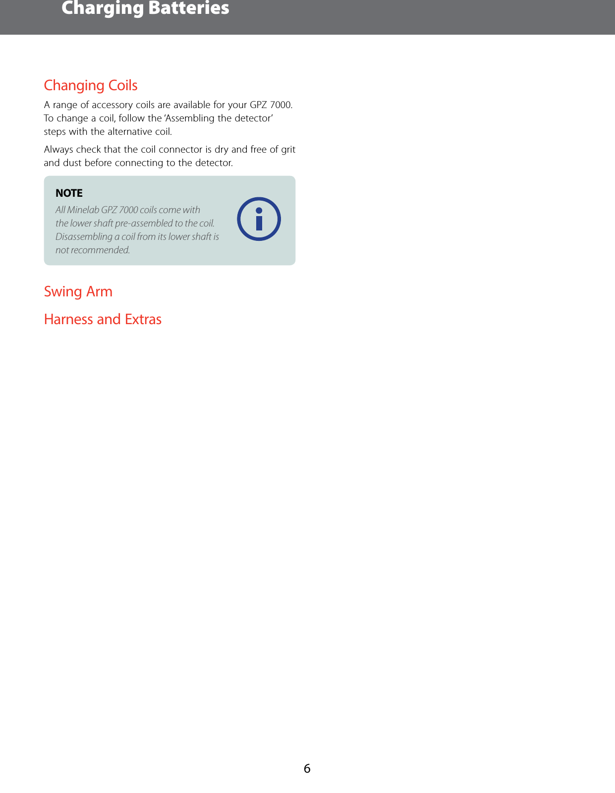
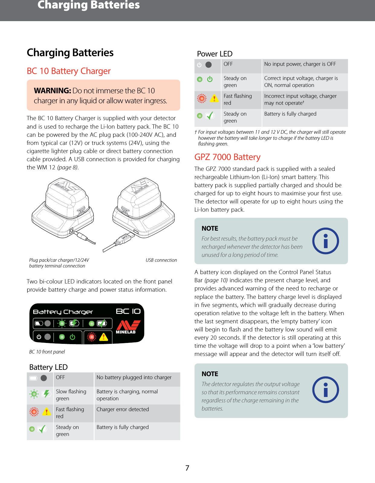
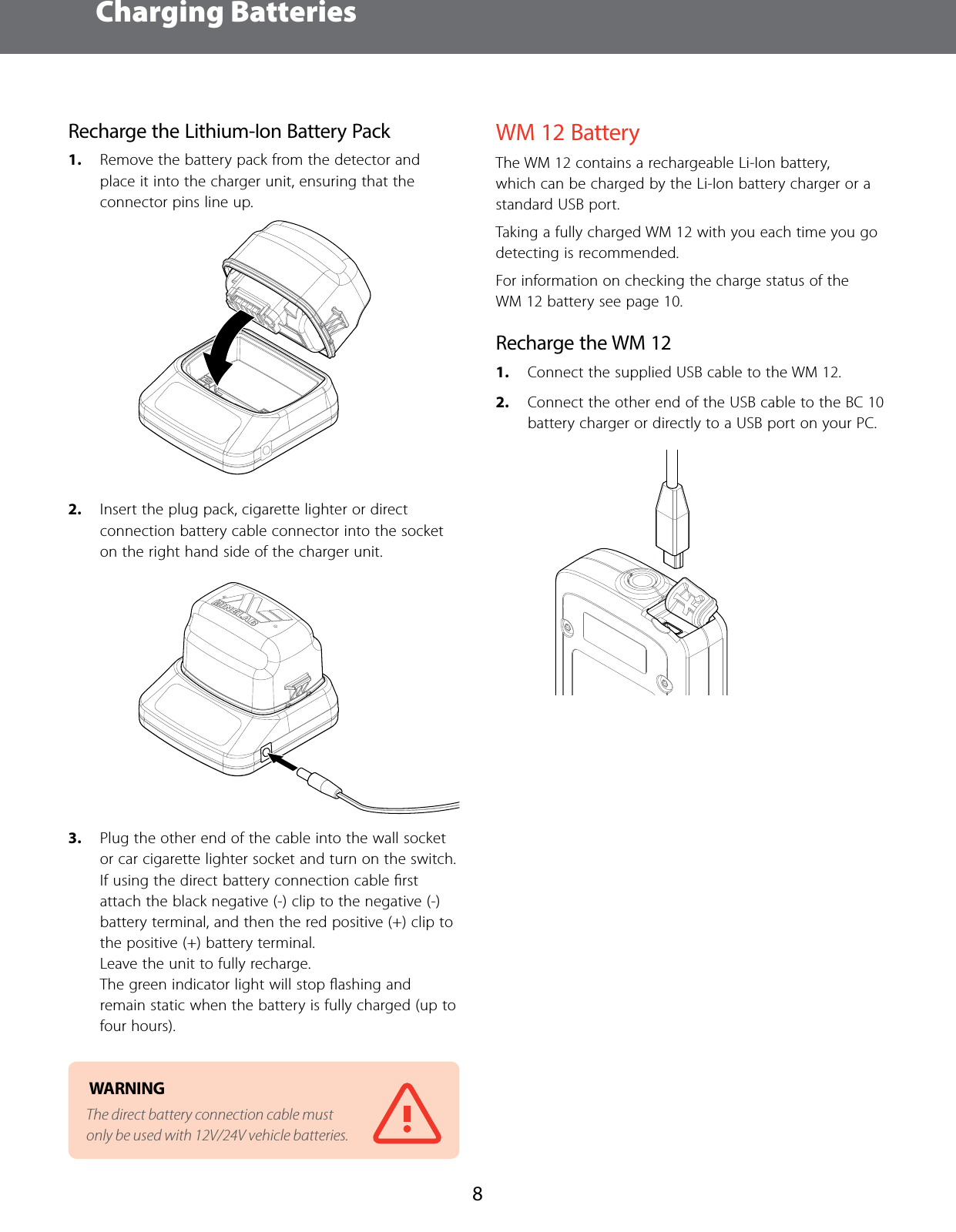
Users Manual
2.
ST Confidentiality for User Manual
Users Manual
Navigation menu
Upload a User Manual
Namespaces
Wiki Guide
HTML
PDF
Info
Views
User Manual
Discussion / Help
Navigation