Minolta Ps7000 Operation And Setup Ps7000pc
PS7000 to the manual 985bb458-63fb-45cc-b2d1-3c70cfc07663
2015-01-05
: Minolta Minolta-Ps7000-Operation-And-Setup-166942 minolta-ps7000-operation-and-setup-166942 minolta pdf
Open the PDF directly: View PDF ![]() .
.
Page Count: 122 [warning: Documents this large are best viewed by clicking the View PDF Link!]
- Welcome
- Introduction
- Organization
- Contents
- Chapter 1
- Chapter 2
- Chapter 3
- Chapter 4
- Chapter 5
- Precautions for operation
- Lamp status
- Turning the Scanner ON and OFF
- Placing the original
- Scanning procedures
- Book/Sheet modes
- Note on originals
- Menu flow chart
- User Mode
- Recalling jobs
- Checking current settings
- Using the edit functions
- Adjusting exposure for scanning
- Selecting resolution
- Selecting scan size
- Selecting Original Type
- Selecting Output Scale
- Selecting Contrast
- Operations in Utility mode
- Chapter 6
- Chapter 7
- Chapter 8
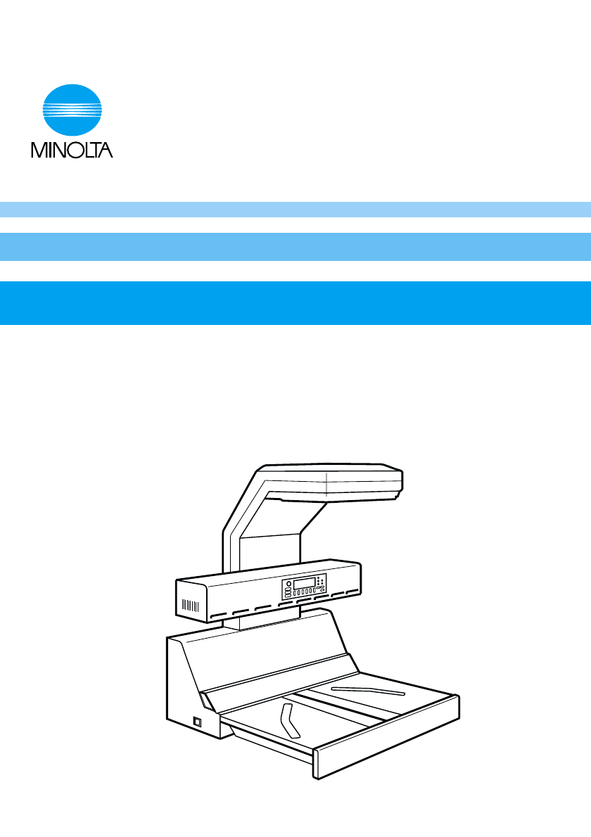
Operator´s Manual
PS7000
0818-7702-23
PC version
P-1
This section contains detailed instructions on the operation and maintenance of this
machine. To achieve optimum utility of this device, all operators should carefully read
and follow the instructions in this manual. Please keep this manual in a handy place
near the machine.
Please read the next section before using this device. It contains important infor-
mation related to user safety and preventing equipment problems.
Make sure you observe all of the precautions listed in this manual.
*Please note that some parts of the contents of this section may not correspond with the
purchased product.
■
■ ■
■ Warning and Precaution Symbols
■
■■
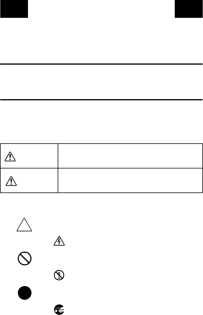
■ Meaning of Symbols
SAFETY INFORMATION
WARNING:
Ignoring this warning could cause serious injury or even
death.
CAUTION:
Ignoring this caution could cause injury or damage to prop-
erty.
A triangle indicates a danger against which you should take
precaution.
This symbol warns against possible electrical shock.
A diagonal line indicates a prohibited course of action.
This symbol warns against dismantling the device.
A black circle indicates an imperative course of action.
This symbol indicates you must unplug the device.
PL 01
P-2
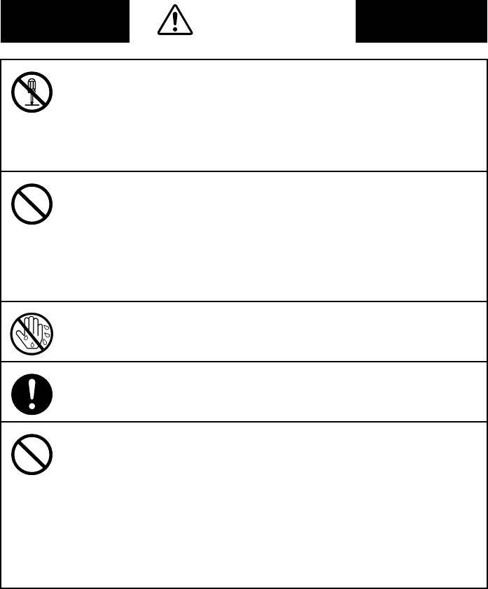
WARNING
•Do not modify this product, as a fire, electrical shock, or breakdown
could result. If the product employs a laser, the laser beam source could
cause blindness.
•Do not attempt to remove the covers and panels which have been fixed
to the product. Some products have a high-voltage part or a laser beam
source inside that could cause an electrical shock or blindness.
•Only use the power cord supplied in the package. Failure to use this
cord could result in a fire or electrical shock.
•Use only the specified power source voltage. Failure to do that could
result in a fire or electrical shock.
•Do not use a multiple outlet adapter to connect any other appliances or
machines. Use of a power outlet for more than the marked current value
could result in a fire or electrical shock.
Do not unplug and plug in the power cord with a wet hand, as an electri-
cal shock could result.
Plug the power cord all the way into the power outlet. Failure to do this
could result in a fire or electrical shock.
•Do not scratch, abrade, place a heavy object on, heat, twist, bend, pull
on, or damage the power cord. Use of a damaged power cord (exposed
core wire, broken wire, etc.) could result in a fire or breakdown.
Should any of these conditions be found, immediately turn OFF the
power switch, unplug the power cord from the power outlet, and then
call your authorized service representative.
•In principle, do not use an extension cord. Use of an extension cord
could cause a fire or electrical shock. Contact your authorized service
representative if an extension cord is required.
P-3
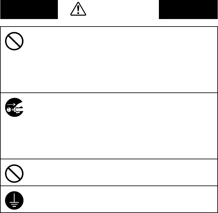
WARNING
Do not place a flower vase or other container that contains water, or
metal clips or other small metallic objects on this product. Spilled water
or metallic objects dropped inside the product could result in a fire, elec-
trical shock, or breakdown.
Should a piece of metal, water, or any other similar foreign matter get
inside the product, immediately turn OFF the power switch, unplug the
power cord from the power outlet, and then call your authorized service
representative.
•If this product becomes inordinately hot or emits smoke, or unusual odor
or noise, immediately turn OFF the power switch, unplug the power cord
from the power outlet, and then call your authorized service representa-
tive. If you keep on using it as is, a fire or electrical shock could result.
•If this product has been dropped or its cover damaged, immediately turn
OFF the power switch, unplug the power cord from the power outlet, and
then call your authorized service representative. If you keep on using it
as is, a fire or electrical shock could result.
Do not throw the toner cartridge or toner into an open flame. The hot
toner may scatter and cause burns or other damage.
Connect the power cord to an electrical outlet that is equipped with a
grounding terminal.
P-4
CAUTION
•Do not use flammable sprays, liquids, or gases near this product, as a
fire could result.
•Do not leave a toner unit or drum unit in a place within easy reach of chil-
dren. Licking or ingesting any of these things could injure your health.
•Do not let any object plug the ventilation holes of this product. Heat
could accumulate inside the product, resulting in a fire or malfunction.
•Do not install this product at a site that is exposed to direct sunlight, or
near an air conditioner or heating apparatus. The resultant temperature
changes inside the product could cause a malfunction, fire, or electrical
shock.
•Do not place the product in a dusty place, or a site exposed to soot or
steam, near a kitchen table, bath, or a humidifier. A fire, electrical shock,
or breakdown could result.
•Do not place this product on an unstable or tilted bench, or in a location
subject to a lot of vibration and shock. It could drop or fall, causing per-
sonal injury or mechanical breakdown.
•After installing this product, mount it on a secure base. If the unit moves
or falls, it may cause personal injury.
•Do not store toner units and PC drum units near a floppy disk or watch
that are susceptible to magnetism. They could cause these products to
malfunction.
The inside of this product has areas subject to high temperature, which
may cause burns. When checking the inside of the unit for malfunctions
such as a paper misfeed, do not touch the locations (around the fusing
unit, etc.) which are indicated by a “Caution! High Temperature!” warn-
ing label.
Do not place any objects around the power plug as the power plug may
be difficult to pull out when an emergency occurs.
P-5
CAUTION
•Always use this product in a well ventilated location. Operating the prod-
uct in a poorly ventilated room for an extended period of time could
injure your health. Ventilate the room at regular intervals.
•Whenever moving this product, be sure to disconnect the power cord
and other cables. Failure to do this could damage the cord or cable,
resulting in a fire, electrical shock, or breakdown.
•When moving this product, always hold it by the locations specified in
the operator’s manual or other documents. If the unit falls it may cause
severe personal injury. The product may also be damaged or malfunc-
tion.
•Remove the power plug from the outlet more than one time a year and
clean the area between the plug terminals. Dust that accumulates
between the plug terminals may cause a fire.
•When unplugging the power cord, be sure to hold onto the plug. Pulling
on the power cord could damage the cord, resulting in a fire or electrical
shock.
P-6
Precautions for Routine Use
•Do not store toner units, PC drum units, and other supplies and con-
sumables in a place subject to direct sunlight and high temperature and
humidity, as poor image quality and malfunction could result.
•Do not attempt to replace the toner unit and PC drum unit in a place
exposed to direct sunlight. If the PC drum is exposed to intense light,
poor image quality could result.
•Do not unpack a toner unit or PC drum unit until the very time of use. Do
not leave an unpacked unit standing. Install it immediately or poor image
quality could result.
•Do not keep toner units and PC drum units in an upright position or
upside down, as poor image quality could result.
•Do not throw or drop a toner unit or PC drum unit as poor image quality
could result.
•Do not use this product in an area where ammonia or other gases or
chemicals are present. Failure to do so may shorten the service life of
the product, cause damage or decrease performance.
•Do not use this product in an environment with a temperature outside
the range specified in the operator’s manual, as a breakdown or mal-
function could result.
•Do not attempt to feed stapled paper, carbon paper or aluminum foil
through this product, as a malfunction or fire could result.
Do not touch or scratch the surface of the toner unit developing roller
and the PC drum, as poor image quality could result.
Use the supplies and consumables recommended by the dealer. Use of
any supply or consumable not recommended could result in poor image
quality and breakdown.
i
Welcome
Thank you for choosing Minolta quality. For over 30 years Minolta has been a leader on the
forefront of office equipment technology and service. Our desire has always been to bring you
highly reliable products. We pledge to continue to provide you, our customer with our state
of the art equipment, as well as full customer service for all our products. We look forward to
a long healthy relationship with you and our company. If you have any questions or comments
about Minolta, our product or service, please let us know. Our fax number is 800-237-8087
(for U.S.A. and Canada). Thank you again.
This operator's manual explains how to operate the unit and replenish its supplies. It also gives
some troubleshooting tips as well as general precautions to be observed when operating the
unit.
To ensure the best performance and effective use of your unit, read this manual carefully until
you familiarize yourself thoroughly with the unit's operation and features.
Please keep this manual and use it as a quick and handy reference tool for immediately clari-
fying any questions that may arise.
Please follow the instructions given in this manual when handling the system and do not touch
any part of the system the manual does not cover.
NEVER attempt to disassemble or remodel the system.
The contents of this manual are subject to change without notice.
No part of this manual may be quoted, reproduced, or translated into any other language.

ii
Introduction
Thank you for choosing our Book Scanner (herein after referred to as the Scanner).
This operator’s manual includes precautions for installation/operation of the Scanner, a
system outline, an explanation of the Driver software, operation procedures for the Scanner,
troubleshooting tips, maintenance, and product specifications.
Before operating the Scanner, read this manual carefully until you familiarize yourself
thoroughly with its operation and features. After you have read through the manual, keep it
for ready reference.
Please also note the following precautions.
Safety Information
All area
Use the shielded cable furnished with the system for this system. Use of an unshielded cable
invites radio frequency interference.
Always refer to this manual when operating the scanner and do not attempt to touch the
scanner parts for which no explanations are given in the text.
NEVER attempt to disassemble or remodel the scanner, as it is very dangerous.
Call your authorized dealer when you want to move a scanner which has been installed.
U.S.A. only
NOTE
This equipment has been tested and found to comply with the limits for a Class A digital
device, pursuant to Part 15 of the FCC Rules. These limits are designed to provide
reasonable protection against harmful interference when the equipment is operated in a
commercial environment. This equipment generates, uses, and can radiate radio frequency
energy and, if not installed and used in accordance with the instruction manual, may cause
harmful interference to radio communications. Operation of this equipment in a residential
area is likely to cause harmful interference in which case the user will be required to correct
the interference at his own expense.
WARNING
The design and production of this unit conform to FCC regulations, and any changes or
modifications must be registered with the FCC and are subject to FCC control. Any changes
made by the purchaser or user without first contacting the manufacturer will be subject to
penalty under FCC regulations.

Introduction
iii
Scanning into a computer and subsequent printing of the following is also prohibited by law
under some circumstances.
1.Paper Money of the United States or any Foreign Government
2.Obligations or Securities of the United States
3.Postage stamps, Postal Money Orders or Internal Revenue Stamps
4.Passports
5.Badges, Identification Card, Passes or Insignia carried by Federal Departments
6.Obligations or Securities of any Foreign Government, Bank or Corporation
The above list is not all inclusive, and no liability is assumed for its completeness. In case
you have doubt, consult your lawyer.
Canada only
This Class A digital apparatus complies with Canadian ICES-003.
Cet appareil numérique de la classe A est conforme à la norme NMB-003 du Canada.
Copyright
Books, magazines, journals and other materials may be cop-
yrighted. Unauthorized scanning into a computer and subse-
quent printing of such copyrighted materials may be contrary
to the provisions of the United States copyright laws, title 17
of the United States Code.
You are encouraged to obtain a license from an organization
such as the Copyright Clearance Center in those circumstanc-
es where it is appropriate.
Post a copy of the above notice where it will be clearly visible
to users of the scanner.

Introduction
iv
Europe only
CE Marking (Declaration of Conformity)
We declare under our sole responsibility that the scanner and options to which this
declaration relates is in conformity with the specifications below.
This declaration is valid for the area of the European Union (EU) only.
Product Type Book Scanner
Product Name PS7000
Options Foot Switch, Grayscale Memory Board
Accessory PC I/F Kit
Standards Safety : EN60 950 / 1992 A1, A2, A3, A4
(Safety of information technology equipment, including
electrical business equipment)
EMC : EN55 022 (Class B) / 1998
(Information technology equipment - Radio disturbance
characteristic - Limits and method for measurement)
EN61000-3-2 /1995 A1, A2
Electromagnetic compatibility (EMC)
— Part 3: Limits — Section 2: Limits for harmonic current
emissions (equipment input current up to and including 16 A
per phase)
EN61000-3-3/1995
Electromagnetic compatibility (EMC)
— Part 3: Limits — Section 3: Limitation of voltage fluctua-
tions and flicker in low -voltage supply systems for equipment
with rated current up to and including 16A
EN50 024 / 1998
(Information technology equipment - Immunity
characteristic - Limits and method for measurement)
EN61000-4-2
(Electromagnetic compatibility (EMC)
Part 4: Testing and measuring techniques
Section 2: Electrostatic discharge immunity test)
EN61000-4-3
(Section 3: Radiated, radio-frequency electromagnetic field
immunity test)
EN61000-4-4
(Section 4: Electrical fast transient/burst immunity test)
EN61000-4-5
(Section 5: Surge immunity test)
EN61000-4-6
(Section 6: Conducted disturbances induced by radio-frequency
fields immunity test)
EN61000-4-8
(Section 8: Power-frequency magnetic field immunity test)
EN61000-4-11
(Section 11: Voltage dips, short interruptions and voltage varia-
tions immunity test)
EC Directives Safety : 73 / 23 / EEC
EMC : 89 / 336 / EEC and 93 / 68 / EEC

Introduction
v
Minolta Co., Ltd. reserves the right to modify this documentation for improvements at any
time without prior notice.
The information disclosed in this documentation, including all designs and related materials,
is the property of Minolta Co., Ltd.
No part of this documentation may be reproduced, transmitted, transcribed, stored in a
retrieval scanner, or translated into other languages without prior written consent from
Minolta Co., Ltd.
Trademark Acknowledgments
Minolta is a registered trademark of Minolta Co., Ltd.
Microsoft, Windows, Windows 95, 98 and Windows NT are registered trademarks of
Microsoft Corporation.
IBM and PC/AT are registered trademarks of International Business Machines Corporation.
Adobe and Adobe Photoshop are trademarks of Adobe Systems Incorporated.
Adaptec and AHA are trademarks of Adaptec, Inc.
ISIS is a registered trademark of Pixel Translations, a division of Input Software, Inc
PixView is a trademark of Pixel Translations, a division of Input Software, Inc
All other brand or product names are trademarks or registered trademarks of their respective
companies or organizations.
Copyright
Books, magazines, journals and other materials may be subject
to copyright. The copying, scanning or altering of such materials
may, unless authorized by the copyright owner, infringe Copy-
right Law. In some countries, there are various types of copying
which will not be treated as copyright infringement such as
research or private study, for criticism or review, for reporting
current events and various acts in relation to education, libraries
and public administration. The scope of these is contained in the
applicable national copyright laws. If you are about to copy, scan
or alter materials and are in any doubt as to whether you will
infringe the copyright (or other rights of the author) you should
seek advice and/or obtain the permission of the author and/or
copyright owner.

vi
Organization
This manual consists of the following seven chapters. Chapters 1 and 2 contain basic
information about the Scanner, including safety precautions for installation/operation,
system configuration, and features. Be sure to read these chapters before using the Scanner.
Chapter 1 Precautions for Installation & Operation
Provides safety precautions required to ensure correct installation and operation of the
Scanner.
Chapter 2 Overview
An overview of the features, system configuration, functions and part names for each
section and control panel.
Chapter 3 PS7000 Twain Driver
Describes installation and start-up procedures for the Twain Driver, as well as the options
available on the image scanning screen.
Chapter 4 PS7000 ISIS Driver
Describes installation and start-up procedures for the ISIS Driver, as well as the options
available on the image scanning screen.
Chapter 5 Operation
Describes operation precautions and procedures (including control panel descriptions),
menu flow charts, and settings for each function.
Chapter 6 Troubleshooting
Describes error and warning messages that appear on the control panel, and procedures for
eliminating these problems.
Chapter 7 Maintenance
Describes daily maintenance required for satisfactory operation of the Scanner.
Chapter 8 Specifications
Complete specifications of the Scanner.
NOTE
In this manual, important points requiring special attention are described in sections
marked with “NOTE”. Messages and menu/command names that appear on the control
panel and computer screen are shown in brackets [ ]. Referenced chapters or their titles are
enclosed by double quotation marks “ ”.

vii
Contents
Chapter 1 Precautions for Installation & Operation
Installation ........................................................................................ 1-1
Installation environment ............................................................ 1-1
Power source .............................................................................. 1-1
Grounding .................................................................................. 1-1
Moving the Scanner ................................................................... 1-2
Space requirements .................................................................... 1-2
Operation .......................................................................................... 1-3
Operating environment .............................................................. 1-3
Precautions when operating the Scanner ................................... 1-3
Precautions when operating the personal computer .................. 1-3
Moving the Scanner ................................................................... 1-4
Chapter 2 Overview
Features ............................................................................................ 2-1
System configuration ....................................................................... 2-2
PC version (connected to a personal computer) ........................ 2-2
PR version (connected to a printer) ........................................... 2-2
Part identification and functions ...................................................... 2-3
Control panel keys ............................................................................ 2-5
Functions of control panel keys ................................................. 2-6
Chapter 3 PS7000 Twain Driver
Installation ........................................................................................ 3-1
System environment .................................................................. 3-1
Installation procedure ................................................................ 3-2
Uninstall ........................................................................................... 3-5
Uninstall procedure .................................................................... 3-5
Start-up ............................................................................................. 3-7
Image acquisition screen .................................................................. 3-9
Chapter 4 PS7000 ISIS Driver
Installation ........................................................................................ 4-1
System environment .................................................................. 4-1
Installation procedure ................................................................ 4-2
Start-up ............................................................................................. 4-5
Image acquisition screen .................................................................. 4-7
Chapter 5 Operation
Precautions for operation ................................................................. 5-1
Lamp status ...................................................................................... 5-2
Half intensity .............................................................................. 5-2
Full intensity .............................................................................. 5-2
Turning the Scanner ON and OFF ................................................... 5-3
Turning on .................................................................................. 5-3

Contents
viii
Turning off ................................................................................. 5-4
Placing the original .......................................................................... 5-5
Scanning procedures ........................................................................ 5-6
Book/Sheet modes .......................................................................... 5-10
Book mode ............................................................................... 5-10
Sheet mode ............................................................................... 5-11
Note on originals ............................................................................ 5-12
Menu flow chart ............................................................................. 5-16
User Mode ...................................................................................... 5-20
Save Data ................................................................................. 5-21
Book / Sheet ............................................................................. 5-22
Sheet mode setting function ..................................................... 5-24
Center Erase ............................................................................. 5-25
Output ...................................................................................... 5-27
Exiting User Mode ................................................................... 5-28
Recalling jobs ................................................................................. 5-29
Checking current settings ............................................................... 5-30
Using the edit functions ................................................................. 5-31
Edit Functions .......................................................................... 5-31
Center Erase (Cent Eras) .......................................................... 5-31
Frame Masking (Masking) ....................................................... 5-32
Finger Masking (Fing Mask) ................................................... 5-33
Centering (Centerin) ................................................................ 5-35
Adjusting exposure for scanning .................................................... 5-36
Auto ......................................................................................... 5-36
Manual adjustment ................................................................... 5-37
Selecting resolution ........................................................................ 5-38
Selecting scan size .......................................................................... 5-39
Scan size in inch ...................................................................... 5-39
Scan size in metric ................................................................... 5-41
Selecting Original Type ................................................................. 5-43
Selecting Output Scale ................................................................... 5-44
Selecting Contrast .......................................................................... 5-45
Operations in Utility mode ............................................................. 5-47
Initial settings ........................................................................... 5-48
Time Set ................................................................................... 5-50
Caution ..................................................................................... 5-52
SCSI port settings .................................................................... 5-54
Exiting Utility mode ................................................................ 5-55
Chapter 6 Troubleshooting
Potential problems ............................................................................ 6-1
Warning message ....................................................................... 6-1
Error message ............................................................................ 6-1
Troubleshooting warning messages ................................................. 6-2

Contents
ix
Chapter 7 Maintenance
Maintenance ..................................................................................... 7-1
Daily checks ............................................................................... 7-1
Cleaning ..................................................................................... 7-1
Chapter 8 Specifications
Product specifications ...................................................................... 8-1
For Key Operator’s Use ................................................................... 8-3

Contents
x

Precautions for Installation & Operation Chapter 1
Chapter 1
Precautions for Installation & Operation

1-1
Precautions for Installation & Operation Chapter 1
Installation
Installation environment
Install the Scanner in a location which meets the following requirements to ensure safe
operation and utmost performance.
◆A place where the illumination onto the book table is less than 1000 lx (e.g. 4.5 m x 6.5 m
area with ceiling height of 2.6 m, and 12 or less 40 W fluorescent lamps).
◆A place where light from the lighting system or the outside through windows does not
reflect on the steel mirror or hit the Scanner unit
◆A place away from curtains or other objects that catch fire and burn easily.
◆A place where there is no possibility of being splashed with water or other liquid.
◆An area free from direct sunlight.
◆A place not in the direct air stream from an air conditioner, heater, and/or ventilator,
ensuring fairly constant temperature.
◆A well-ventilated place.
◆A dry place.
◆A dust-free location.
◆An area not subject to undue vibration.
◆A stable and level surface.
Power source
The power source voltage requirements are as follows.
◆Use a power source with little voltage/frequency fluctuations.
Voltage fluctuation: 120 VAC ±10%, 220-240 VAC ±10%
Frequency fluctuation: 50 Hz ±3 Hz
60 Hz ±3 Hz
◆If any other electrical equipment uses the same power outlet, make sure that the capacity
of the outlet is not exceeded.
◆The outlet should be located near the Scanner and easily accessible so that power cord can
be disconnected whenever necessary.
◆NEVER use a multiple adapter to connect other equipment or machines to the outlet used
by the Scanner.
◆If an extension cord is required, use one with a capacity higher than the power consump-
tion of the Scanner.
◆Make sure that no unusual, excessive force is applied to the power cord or extension cord.
Grounding
Connect the Scanner’s ground wire to any of the following to prevent electrical shocks due
to electrical leakage.
◆Ground terminal of the outlet.
◆Ground contact that complies with local electrical standards.
Never connect the ground cable to a gas pipe, ground wire for a telephone line, or a water
pipe.
Installation
1-2
Precautions for Installation & Operation Chapter 1
Moving the Scanner
Please contact your authorized dealer before moving the Scanner to a new installation
location.
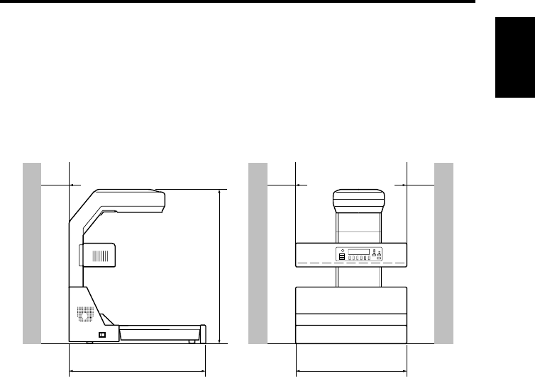
Space requirements
◆Secure the recommended space shown in the figure below to ensure easy operation and
maintenance of the Scanner.
730 mm
150 mm 150 mm 150 mm
745 mm
975 mm
5-7/8"
29-3/8"
5-7/8" 5-7/8"
28-3/4"
38-3/8"

1-3
Precautions for Installation & Operation Chapter 1
Operation
Operating environment
The following environment is required for consistent performance of the Scanner.
Temperature: 50 to 95°F (10 to 35°C) with temperature variation not exceeding 50°F
(10°C) per hour
Humidity: 15 to 85%RH with humidity variation not exceeding 20%RH per hour
Precautions when operating the Scanner
Observe the following precautions to ensure the optimum performance of the Scanner.
◆NEVER place any object other than the original on the book table or apply excessive
pressure to the book table.
◆NEVER turn the power switch off during operation.
◆NEVER bring any magnetized object or use flammable sprays/liquids near the Scanner.
◆NEVER place a vase or vessel containing water on the Scanner.
◆NEVER drop paper clips, staples, or other small pieces of metal into the Scanner. If this
occurs, contact your authorized dealer.
◆NEVER remove the shading plate (refer to page 2-3), outer cover, mirror, or control
panel. Always keep the shading plate clean (refer to page 7-1).
◆NEVER place the Scanner or the cabinet on the power cord or interface cables of other
electrical equipment.
◆NEVER leave a damaged or cracked power cord or interface cable unrepaired. If any of
these conditions are found, immediately shut down the Scanner, unplug the power cord,
and call your authorized dealer for appropriate action.
◆NEVER place an object on the lamp unit.
◆ALWAYS completely insert the power cord plug into the power outlet.
◆ALWAYS make sure that the outlet into which the power cord plug is inserted is visible.
◆ALWAYS be sure to turn the power switch off, unplug the power cord, and call your
authorized dealer for appropriate action when the Scanner becomes excessively hot or
produces abnormal noise.
◆NEVER place the original or any other object in front of the exhaust outlet of the cooling
fan located on either side of the product body, or the exhaust outlet will be blocked, caus-
ing the failure to the product.
NOTE
We recommend that you take a 5 minute break every hour to rest your eyes when operating
the Scanner.
Precautions when operating the personal computer
Refer to the operation manual provided for the personal computer.
Operation
1-4
Precautions for Installation & Operation Chapter 1
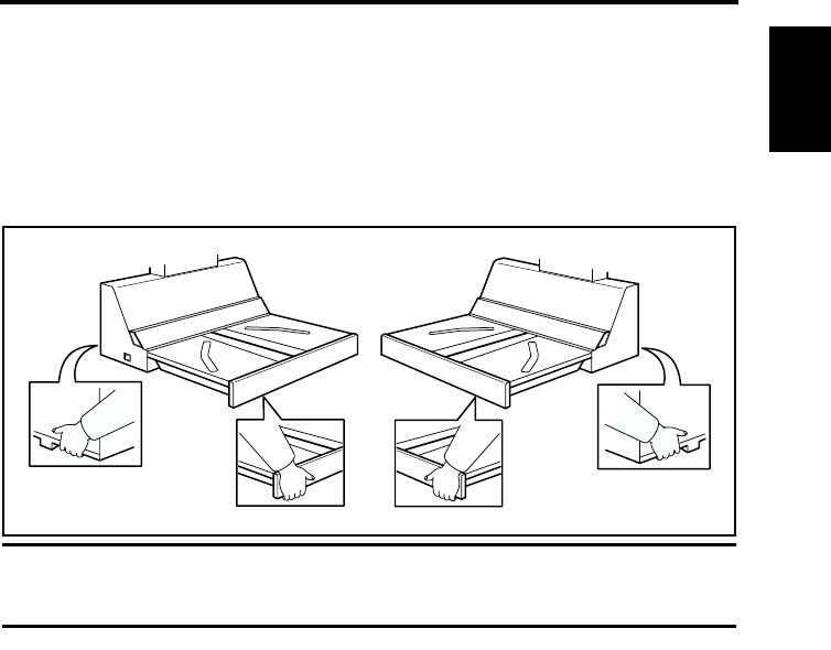
Moving the Scanner
When moving the Scanner, observe the following.
◆The Scanner body weighs 64 kg. When carrying the Scanner, hold the parts identified
with arrows in the below figure. Be careful not to hurt your back or waist. Do not carry
the Scanner alone but with your mate or mates.
◆When moving the Scanner, be sure to disconnect the power cord and the interface cable.
◆When transporting the Scanner, contact your authorized Dealer.
NOTE
Never hold any parts other than the parts identified with arrows in the figure (e.g.,lamp
cover, book table), or the Scanner may have trouble.

Operation
1-5
Precautions for Installation & Operation Chapter 1

Overview Chapter 2
Chapter 2
Overview
2-1
Overview Chapter 2
Features
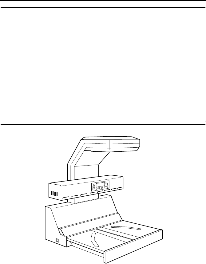
The Scanner is designed to scan books set face up on the book table. This makes setting the
book very easy and reduces concerns that the book may be creased or damaged. In addition,
warped text lines and text compression are corrected, ensuring clearer images. Various
options such as a foot switch etc. are also provided.
2-2
Overview Chapter 2
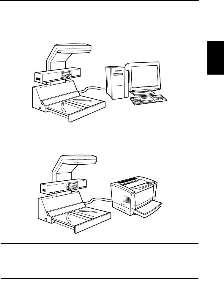
System configuration
The Scanner is available in the following configurations.
PC version (connected to a personal computer)
The Scanner is connected to a personal computer and the scanned images can be uploaded
to the computer.
PR version (connected to a printer)
The Scanner is connected to a dedicated printer, allowing scanned images to be printed
out directly.
◆This manual describes the PC version.
NOTE
• Connection to a personal computer and printer can be switched using [Output] in the
[User Mode] menu.
• A dedicated printer and the corresponding PR interface kit are required for connection to
a printer. Contact your authorized dealer for details.
2-3
Overview Chapter 2
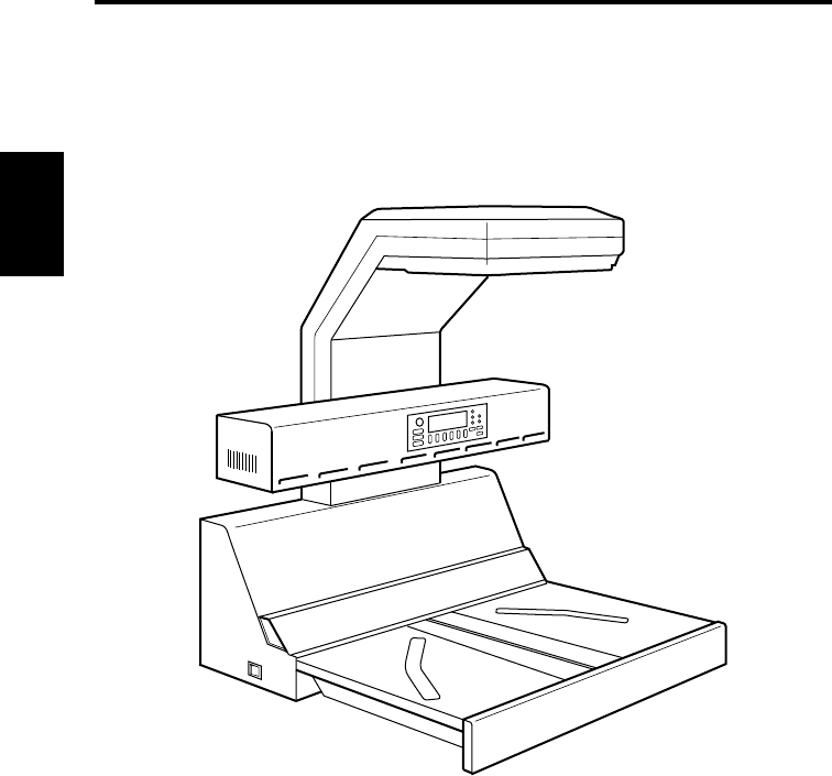
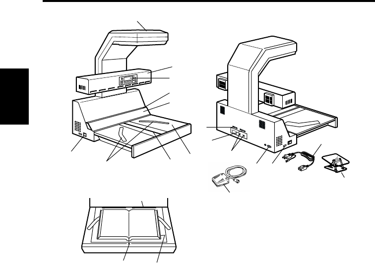
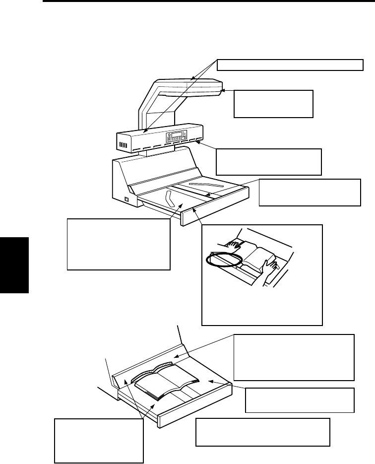
Part identification and functions
1. Scanner unit: The CCD sensor housed in this unit scans the original.
2. Lamp unit: Illuminates the original when the scanner unit reads the
image.
3. Control panel: Used to set the operating mode, and displays operating
status and error/warning messages.
4. Shading plate: Used to adjust the exposure.
5. Steel mirror: Detects the position (height) of the original.
6. Book table: Place the original (book) face up on this table.
7. Table center: When a special binder or the like is used for the spine
(binding part) and the height of the original is 65 mm or
more, this center of the book table is pushed down to
lower the spine (binding part) of the original to a height
acceptable for scanning.
8. Start key: Press this key to start scanning the original.
9. Power switch: Turns the Scanner on and off.
10. Printer connector: Connect the printer cable to this connector.
1
2
5
9
86
4
3
10
11
12
13 16
14
7
15
17
18
20
19

Part identification and functions
2-4
Overview Chapter 2
11. SCSI connector: Connect the SCSI cable included in the interface kit.
When multiple SCSI devices are connected to the
personal computer, connect the Scanner at the end of the
SCSI chain. (Optional PC interface kit is required)
The total length of the SCSI cables must be 6 m or less
when used for daisy-chaining all the SCSI units alone or
3 m or less when used for daisy-chaining all the SCSI
units and SCSI-2 units.
12. Foot switch connector: Connect the foot switch (option) cable to this connector.
Use the left terminal (viewed from the rear) to read the
right page when the foot switch is pressed, and the right
terminal for the left page. Either terminal can be used
when reading two spread pages.
13. Power cord socket: Plug the power cord into this socket.
14. Power cord: Connects the Scanner to the power outlet.
15. Foot switch (option): Press this switch instead of the start key on the book
table to start scanning. Used when a large original is
covering the start key.
16. Counter: Counts the number of originals scanned.
17. Angle book holder (option): Used to scan the original whose spine (binding part)
should not be damaged (e.g., precious book).
18. Stopper: Used as the reference position for the original. When
placing the original, align its top edge with this position.
19. Center mark: Adjust the center of the original to this mark.
20. Size guide: Indicates the scannable range of the original.
2-5
Overview Chapter 2
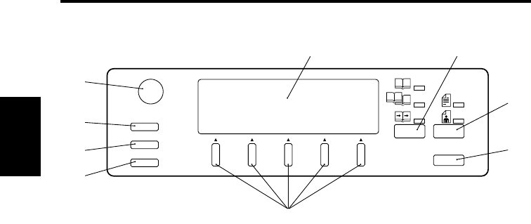
Control panel keys
1. Contrast knob: Adjusts the contrast (luminosity) of the display.
2. User Mode key: Allows you to customize settings.
3. Job Recall key: Recalls settings previously registered in User Mode.
4. Mode Check key: Displays the current settings.
5. Display: Displays current status, operation instructions, warning
messages, and functions available for selection.
6. Selection keys: Used to select functions shown on the display.
7. Page Selection key: Used to select [Spread] scanning (two pages), [Single]
scanning (either right or left page only), or [Book Split]
scanning (right and left pages separately).
8. Image key: Used to select the image type (Text or Photo).
9. Panel Reset key: Resets the settings to defaults.
User Mode Book Split
Contrast
Job Recall
Mode Check Panel Reset
Single
Photo
Text
Spread
7
1
8
9
5
2
3
4
6
Control panel keys
2-6
Overview Chapter 2
Functions of control panel keys
The control panel keys control the following functions.
1. Contrast knob
Adjusts the contrast (luminosity) of the display.
Turning the volume clockwise and counterclockwise increases and decreases the contrast
respectively.
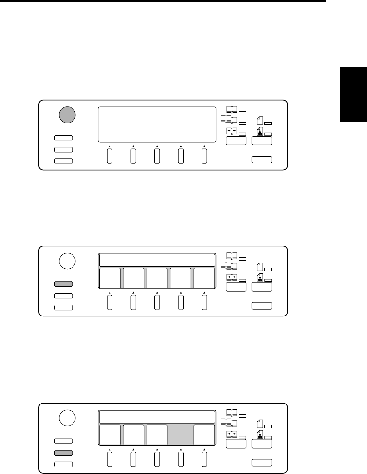
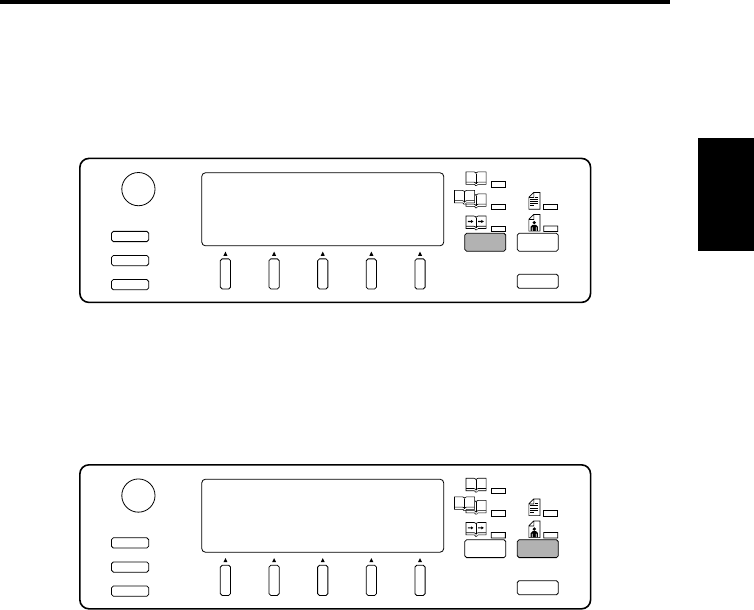
2. User Mode key
Customized settings can be stored.
Pressing this key displays the user mode menu. The desired menu can be selected by
pressing the relevant selection key.
Refer to page 5-16 “Menu flow chart” for details of each menu.
3. Job Recall key
Recalls settings previously registered in User Mode.
Pressing this key displays preset programs (scanner settings). The desired program can
be selected by pressing the relevant selection key.
Press the User Mode key and select [Save Data] when registering a job.
User Mode Book Split
Contrast
Job Recall
Mode Check Panel Reset
Single
Photo
Text
Spread
User Mode Book Split
Contrast
Job Recall
Mode Check Panel Reset
Single
Photo
Text
Spread
Save
Data
Book
Sheet
Cent
Eras
Out
put
Prev
ious
Set User Choice
User Mode Book Split
Contrast
Job Recall
Mode Check Panel Reset
Single
Photo
Text
Spread
NO.1 NO.2 NO.3 Prev
ious
Recall Settings
Control panel keys
2-7
Overview Chapter 2
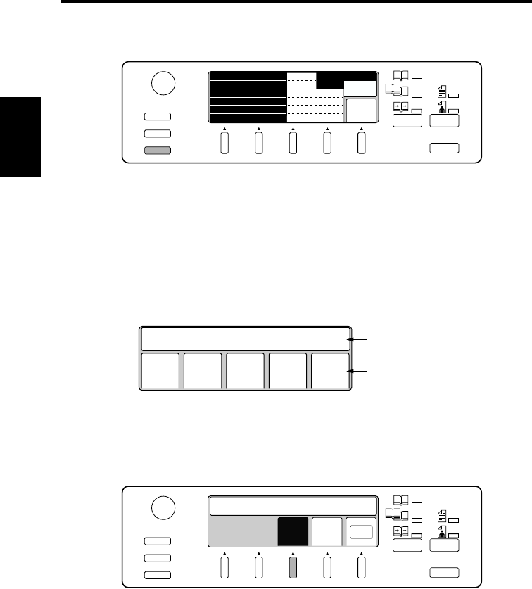
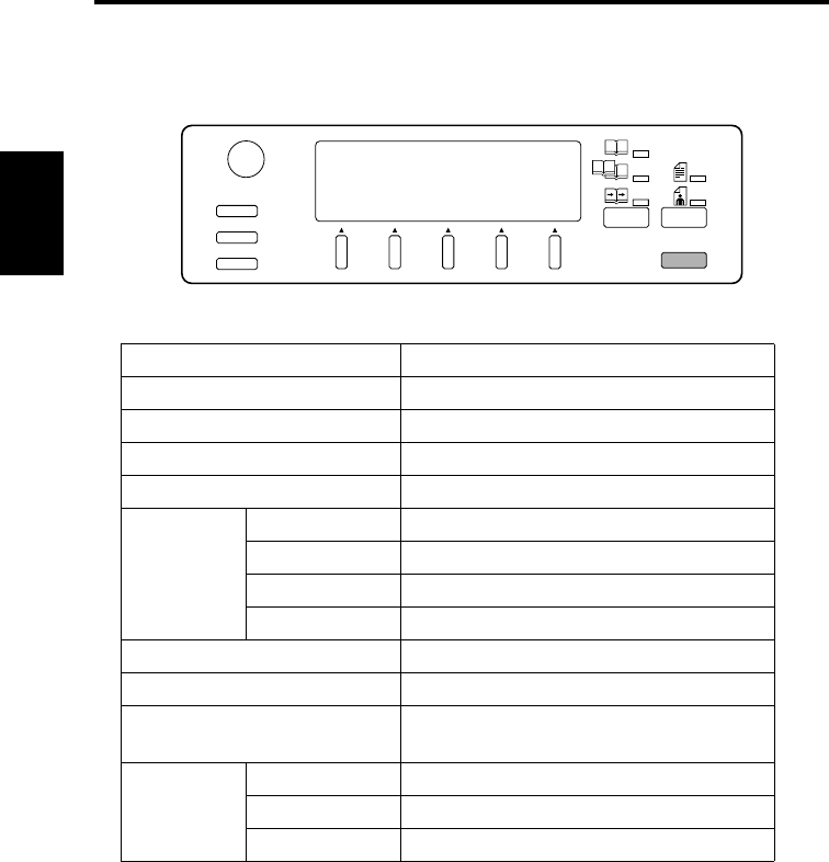
4. Mode Check key
Pressing this key displays current settings.
5. Display
Operating status, operation instructions, warning messages, and available functions are
displayed here.
Message area: Operating status, operation instructions, warning messages, and settings
(number of pages to be scanned, resolution, etc.) are displayed here.
Function area: Available functions are displayed here. Use the selection keys below the
display to select or set functions. The specified function is highlighted.
6. Selection keys
These keys are used to select the functions displayed. Press the key immediately below
the desired item to select it. The specified item is highlighted when selected.
User Mode Book Split
Contrast
Job Recall
Mode Check Panel Reset
Single
Photo
Text
Spread
Next
FRAME MASK CENTERINGON
OFF
Book Auto
PC
FINGER MASK
CENTER ERASE
ORIGINAL
CONNECTION
OFF
OFF
Save
Data
Message area
Function area
Book
Sheet
Cent
Eras
Out
put
Prev
ious
Set User Choice
User Mode Book Split
Contrast
Job Recall
Mode Check Panel Reset
Single
Photo
Text
Spread
PC OK
Set Output Device
Prin
ter
Control panel keys
2-8
Overview Chapter 2
7. Page key
The type of scanning is selected. The lamp of the selected mode lights.
Spread: Both pages are scanned as one sheet.
Single: Only the right or left page is scanned.
Book Split: Right and left pages are scanned separately.
8. Image key
The image type can be selected to suit the original. The lamp of the selected mode lights.
Text: Suitable for scanning text. The outline is accentuated to obtain a clearer image.
Photo: Suitable for scanning photographs. Half tones can be reliably reproduced.
User Mode Book Split
Contrast
Job Recall
Mode Check Panel Reset
Single
Photo
Text
Spread
User Mode Book Split
Contrast
Job Recall
Mode Check Panel Reset
Single
Photo
Text
Spread
Control panel keys
2-9
Overview Chapter 2
9. Panel Reset key
Pressing this key returns all settings to their default settings, and displays the main menu.
All settings revert to default settings when the power switch is turned on.
Default settings are as follows.
Default settings can be changed in Utility mode. Refer to page 5-47 for details.
Item Default Setting
Connect PC
Book/Sheet Book mode
Page Spread
Image Text
Edit
Center erase OFF (width: 5 mm, position: Auto)
Frame masking ON
Finger masking OFF
Centering OFF
Exposure Auto (Center)
Resolution 600 dpi
Size A3 Landscape (Metric Area)
11” x 17” Landscape (Inch Area)
Quality
Original Type Auto
Scale 2 scale (binary)
Contrast ❍ (0), ● (0)
User Mode Book Split
Contrast
Job Recall
Mode Check Panel Reset
Single
Photo
Text
Spread

PS7000 Twain Driver Chapter 3
Chapter 3
PS7000 Twain Driver

3-1
PS7000 Twain Driver Chapter 3
Installation
The PS7000 Twain Driver (hereinafter referred to as the Driver) must be installed on the
personal computer connected to the Scanner to read images from it. This chapter describes
the system requirements of the personal computer and the installation procedures of the
Driver. Moreover, please read the Readme.txt file in the floppy disk of Twain Driver.
System environment
The following are the minimum system requirements for the computer connected to the
Scanner to install the Driver.
The operator should be completely familiar with basic Windows operations.
NOTE
Before installing PS7000 Twain Driver, install Adaptec Aspi Ver. 4.6 or advanced in your
PC. If Adaptec Aspi is older than Ver. 4.6, PS7000Twain driver will not work.
Adaptec Aspi is not supplied together with the product.
Obtain the [Windows 95/98/NT 4.0 ASPI32.EXE] file from [update of Windows 95/98/NT
4.0 mini-port driver ASPI layer] available in the Adaptec's home page.
Computer Compatible with IBM PC/AT
OS WindowsNT4.0, Windows95, Windows98
Required memory Grayscale Scan:
Max. 68 MB or less for the Twain driver only
Binary Scan:
Max. 10MB or less for the Twain driver only
(additional memory required for the OS and other
applications)
Application software Application software compatible with Twain32
(32-bit application compatible with Windows95/98/NT)
Recommended SCSI
Host Adapter
SCSI Host Adapter manufactured by Adaptec
(AHA-2940Ultra, 2940AU, 2930U)
Installation
3-2
PS7000 Twain Driver Chapter 3
Installation procedure
Follow the procedure below to install the Driver.
*Screens may differ slightly depending on the Windows version.
Check that the Scanner is connected to the personal computer.
Turn on the power switch of the Scanner (refer to “Turning on” on page 5-3), and then
turn the personal computer on to start Windows.
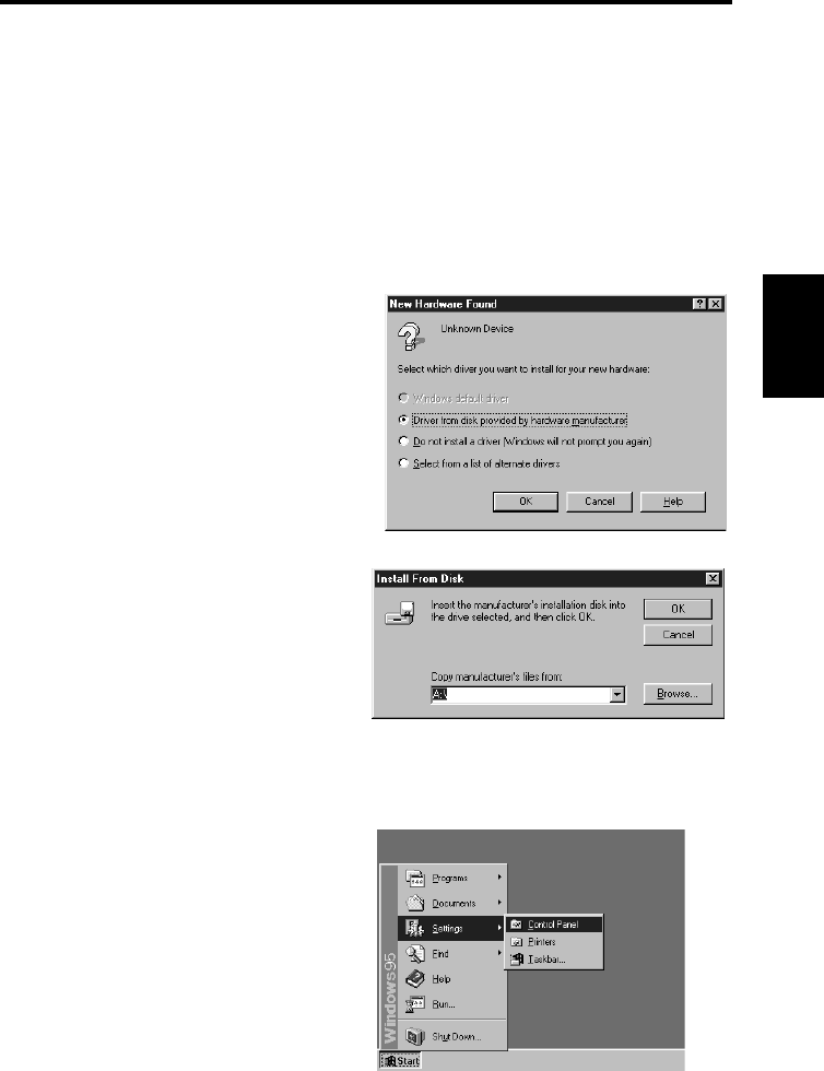
[When using Windows95]
Select [Driver from disk provided by
hardware manufacturer] and click the
[OK] button when the following screen
appears.
The screen shown below appears.
Insert the Twain Driver floppy disk
into the floppy disk drive (generally
drive “A”) of the personal computer
and click the [OK] button.
After window’s has started, set the Twain Driver floppy disk into the computer’s
floppy desk drive.
Click the [Start] button and select
[Settings] → [Control Panel].
1
2
3
4
Installation
3-3
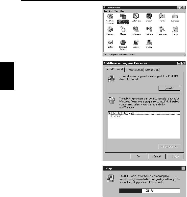
PS7000 Twain Driver Chapter 3
Double-click [Add/Remove
Programs].
Select the [Install/Uninstall] tab.
Click the [Install...] button.
A screen appears informing you that
the driver is preparing for set up.
5
6
7
Installation
3-4
PS7000 Twain Driver Chapter 3
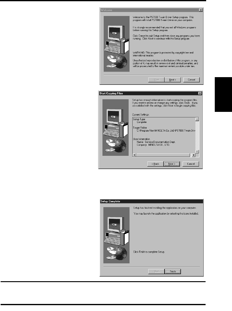
The installation confirmation
screen appears. Click the [Next >]
button to start installation.
The confirmation screen to start
copying appears. Check the
current settings and click the [Next
>] button.
Copying files is started.
The complete setup confirmation
screen appears. Click the [Finish]
button to complete installation.
NOTE
Eject the installation floppy disk from the computer and restart Windows after installation
has been completed.
8
9
10
11
3-5
PS7000 Twain Driver Chapter 3
Uninstall
Remove the Driver from the computer when it is no longer required.
Uninstall procedure
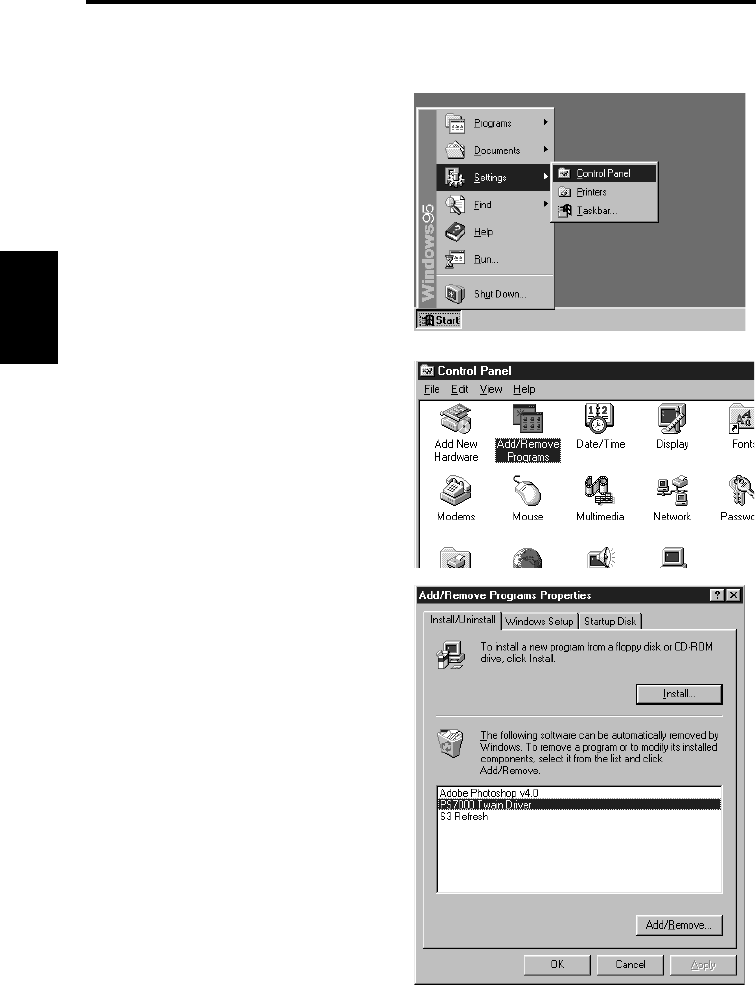
Click the [Start] button and select
[Settings] → [Control Panel].
Double-click [Add/Remove
Programs].
Select the [Install/Uninstall] tab.
Select [PS7000 Twain Driver] from
the list and click the [OK] button.
1
2
3
Uninstall
3-6
PS7000 Twain Driver Chapter 3
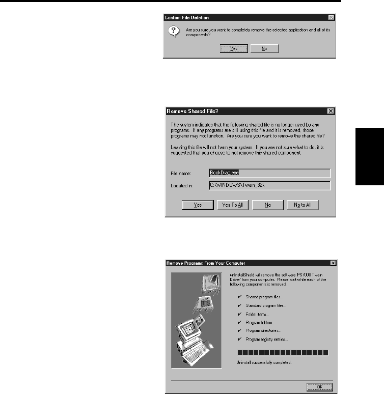
The uninstall confirmation screen
appears. Click the [Yes] button to
start uninstallation.
The “Remove Shared File?” screen
appears. Click the [Yes to All]
button.
The screen indicates the shared
files are being deleted. Click the
[OK] button when completed.
4
5
6
3-7
PS7000 Twain Driver Chapter 3
Start-up
The Driver can be started from any Twain compatible application. The start up procedure
when using Adobe Photoshop 4.0 is described below.
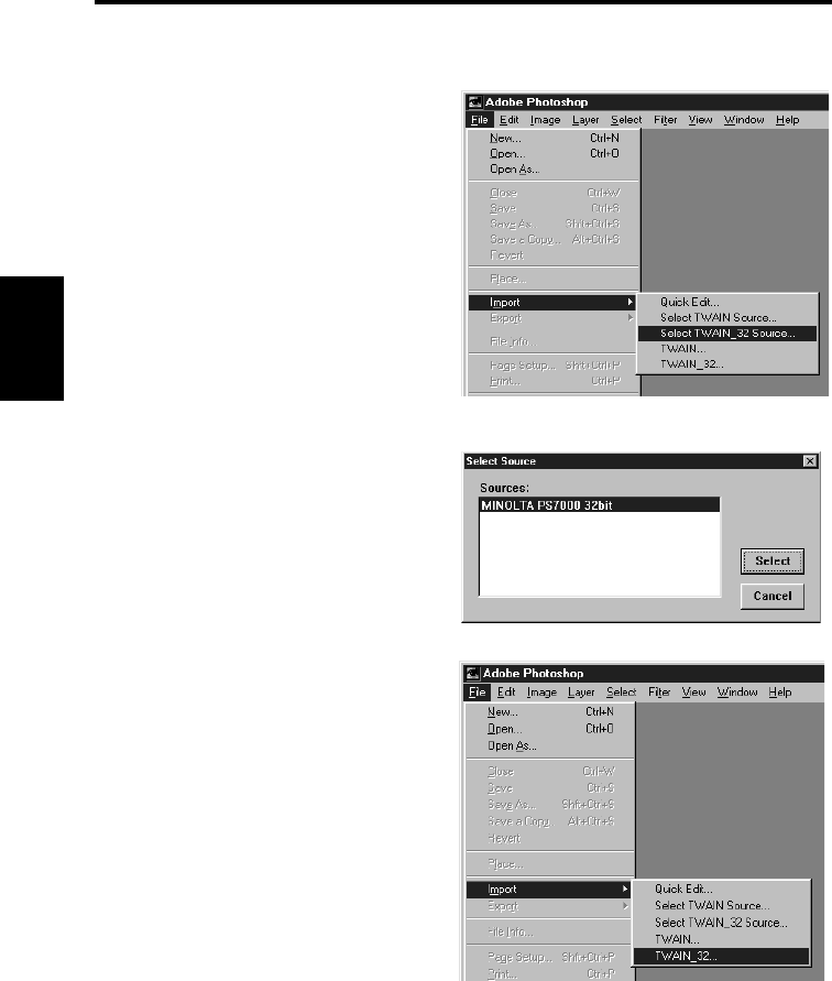
Start Adobe Photoshop 4.0.
Select [File] → [Import] → [Select
Twain_32 Source].
Select [MINOLTA PS7000 32bit]
in the Select Source screen and
click the [Select] button.
Steps 1 and 2 described above are
not required if no other Twain
device is being used.
Select [File] → [Import] →
[Twain_32...].
1
2
3
Start-up
3-8
PS7000 Twain Driver Chapter 3
A screen with basic settings for
reading images appears.
Click the [Detail] tab to show the
detailed setting screen.
NOTE
Relevant settings on the image acquisition screen must be completed before the image is
loaded to the personal computer.
Click the [Cancel] button and exit the image acquisition screen in order to save or edit the
loaded image.
4-1
4-2
3-9
PS7000 Twain Driver Chapter 3
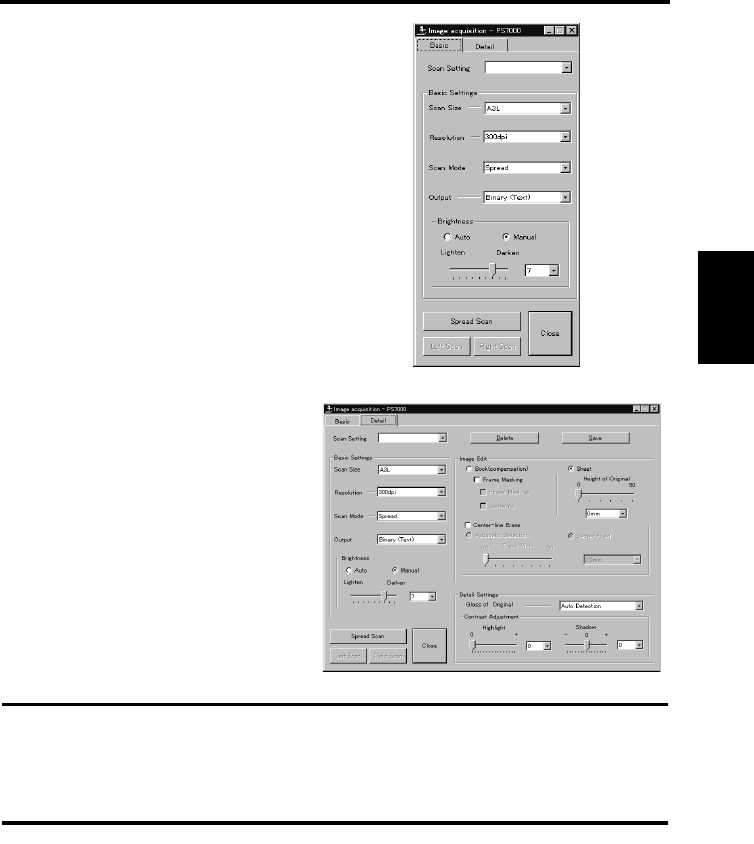
Image acquisition screen
Images can be loaded and function settings made from the personal computer using the
Image acquisition screen.
Settings on the screen are interlocked with the Scanner’s control panel, meaning that
changes made from the personal computer are also applied to the Scanner’s control panel, or
vice versa.
Each item is described below, with the corresponding Scanner setting indicated by a
reference page. Refer to the specified page for details.
1. Scan Setting: Specify the name assigned when registering settings in the
Image acquisition screen, or specify the registered settings to
be recalled or deleted by entering the name.
Enter alphanumeric characters.
Select the desired name from the pull down list to recall
settings.
2. Delete: Deletes previously registered settings.
Recall settings to be deleted and click this button.
3. Save: Saves the current settings.
Enter the name and click this button.
4. Scan Size: Set the size of the original to be read.
Refer to “Selecting scan size” on page 5-39 for details.
5. Resolution: Set the resolution of the image output.
Refer to “Selecting resolution” on page 5-38 for details.
2
4
1
5
6
7
8
9
3
10
11
12
13
14
15
16
17

Image acquisition screen
3-10
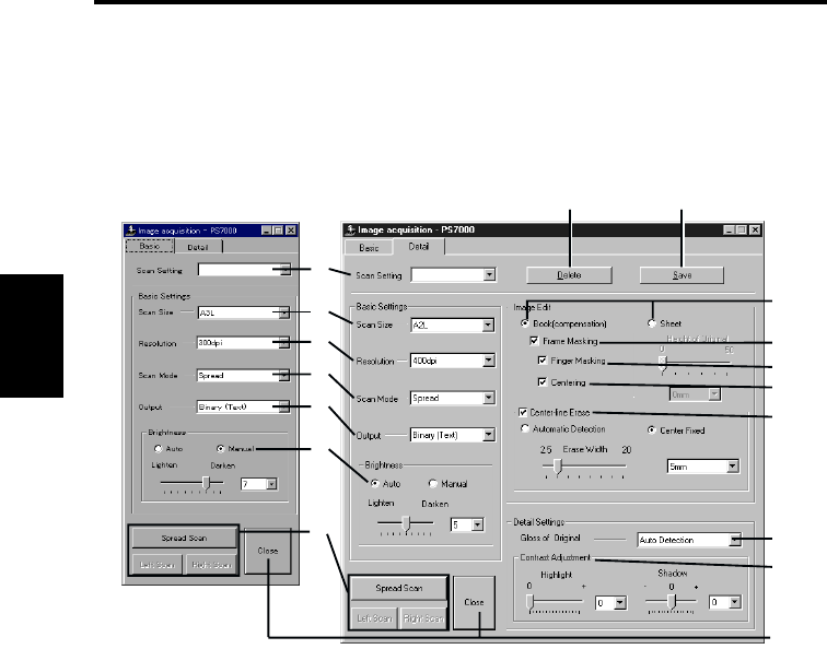
PS7000 Twain Driver Chapter 3
6. Scan Mode: Select [Spread] (scanning both pages), [Single] (scanning
either right or left page only), or [Book Split] (scanning right
and left pages separately).
Refer to “7. Page key” on page 2-8 for details.
7. Output: Selects the mode (Text or Photo).
Add a grayscale memory (option).
Selection is available from among 4 choices: Binary (Text),
Binary (Photo), Grayscale (Text) and Grayscale (Photo).
8. Brightness: Select [Auto] or [Manual].
Brightness is adjusted manually when [Manual] is selected.
Brightness is adjusted automatically according to the
original when [Auto] is selected, however, further fine
adjustment is also available.
Refer to “Adjusting exposure for scanning” on page 5-36 for
details.
9. Scan buttons: These are the same as the start buttons on the Scanner.
Click the [Spread Scan] button to read both pages of the
book on the table. This button is effective when Scan Mode
is set to [Spread] or [Book Split].
Click the [Right Scan] or [Left Scan] to read only right or
left page of the book on the table. This button is effective
only when Scan Mode is set to [Single].
10. Book / Sheet: Set the type (shape) of the original.
When [Sheet] is selected, the height of the original can be
adjusted.
Refer to “Book/Sheet modes” on page 5-10 for details.
11. Frame Masking: Objects outside the original are erased to prevent a
shadowed (black) frame being created in the image, i.e.
when the paper selection is larger than the original.
Refer to “Frame Masking (Masking)” on page 5-32 for
details.
12. Finger Masking: The image of the fingers holding the original is removed
from the scanned image. This function is effective when
[Frame Masking] is selected.
Refer to “Finger Masking (Fing Mask)” on page 5-33 for
details.
13. Centering: Any shift away from the center of the original is corrected
and the scanned image is placed in the center of the screen.
This function is effective when [Frame Masking] is selected.
Refer to “Centering (Centerin)” on page 5-35 for details.

Image acquisition screen
3-11
PS7000 Twain Driver Chapter 3
14. Center-line Erase: The shadow generated in the center of the open book is
erased during scanning.
[Automatic Detection] automatically determines the center
of the original. This is effective only in Book mode.
The center of the book table is regarded as the center of
original when [Center fixed] is selected.
The erasing range (width) can also be adjusted.
Refer to “Center Erase (Cent Erase)” on page 5-31 for
details.
15. Gloss of Original: Selects the type of the original.
“Auto Detection” is selected for standard use, but “Normal”
or “Glossy” can also be selected.
Refer to “Selecting Original Type” on page 5-43 for details.
16. Contrast Adjustment: Adjusts the contrast for reading the original.
Refer to “Selecting Contrast” on page 5-45 for details.
17. Close: Exit the image acquisition screen.

PS7000 ISIS Driver Chapter 4
Chapter 4
PS7000 ISIS Driver

4-1
PS7000 ISIS Driver Chapter 4
Installation
The PS7000 ISIS Driver (hereinafter referred to as the Driver) must be installed on the
personal computer connected to the Scanner to read images from it. This chapter describes
the system requirements of the personal computer and the installation procedures of the
Driver.
System environment
The following are the minimum system requirements for the computer connected to the
Scanner to install the Driver.
The operator should be completely familiar with basic Windows operations.
Computer Compatible with IBM PC/AT
OS WindowsNT4.0, Windows95
Memory At least 32MB of PC RAM
(64MB recommended)
Application software Application software compatible with ISIS
Recommended SCSI
Host Adapter
SCSI Host Adapter manufactured by Adaptec
(AHA-2940Ultra)
Installation
4-2
PS7000 ISIS Driver Chapter 4
Installation procedure
Follow the procedure below to install the Driver.
*Screens may differ slightly depending on the Windows version.
Check that the Scanner is connected to the personal computer.
Turn on the power switch of the Scanner (refer to “Turning on” on page 5-3), and then
turn the personal computer on to start Windows.
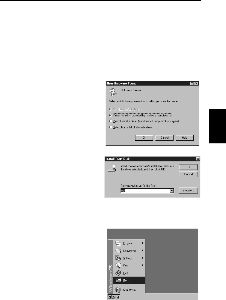
[When using Windows95]
Select [Driver from disk provided by
hardware manufacturer] and click the
[OK] button when the following screen
appears.
The screen shown below appears.
Insert the ISIS Driver floppy disk into
the floppy disk drive (generally drive
“A”) of the personal computer and
click the [OK] button.
After window’s has started, set the ISIS Driver floppy disk into the computer’s floppy
desk drive.
Click the [Start] button and select
[Run…].
1
2
3
4
Installation
4-3
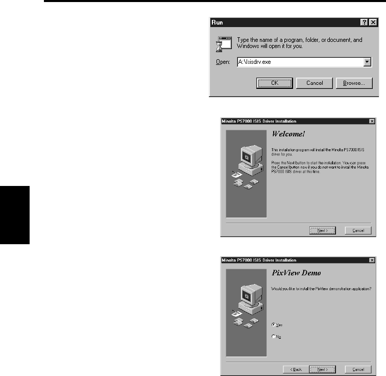
PS7000 ISIS Driver Chapter 4
Input “A:\Isisdrv.exe” for the
name, and click the OK button
(when the drive is A is used).
The installation confirmation screen
appears. Click the [Next >] button to
start installation.
PS7000 is supplied with an
application software “PixView” for
ISIS.
To install this software after the
installation of the ISIS driver, select
“Yes” and click the [Next] button.
To use other software for ISIS, select
“No” and click the “Next” button.
5
6
7
Installation
4-4
PS7000 ISIS Driver Chapter 4
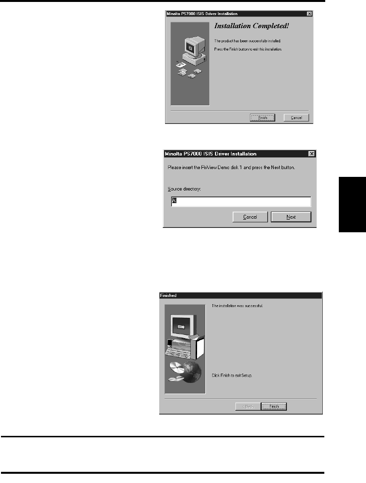
When the installation is completed,
the screen shown on the right
appears. Then, click the [Finish]
button.
When “No” is selected in the step 8,
it completes the installation.
When “Yes” is selected in the step 8
and the installation of the ISIS driver
is completed, the screen shown on the
right appears.
Insert the floppy disk “PixView Disk
1/3” into the floppy disk driver of
your PC, and click the [Next] button.
For the subsequent work, follow the
instructions that will appear on the
screen.
The complete setup confirmation
screen appears. Click the [Finish]
button to complete installation.
NOTE
Eject the installation floppy disk from the computer and restart Windows after installation
has been completed.
8
9
10
4-5
PS7000 ISIS Driver Chapter 4
Start-up
The Driver can be started from any ISIS compatible application. The start up procedure
when using PixView 3.0 is described below.
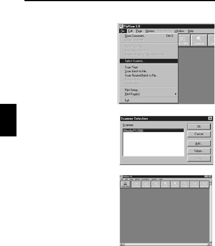
Start PixView 3.0.
Select [File] → [Select Scanner].
Select [Minolta PS7000] in the Select
Source screen and click the [Select]
button.
Click [Scan Setup] button.
1
2
3
Start-up
4-6
PS7000 ISIS Driver Chapter 4
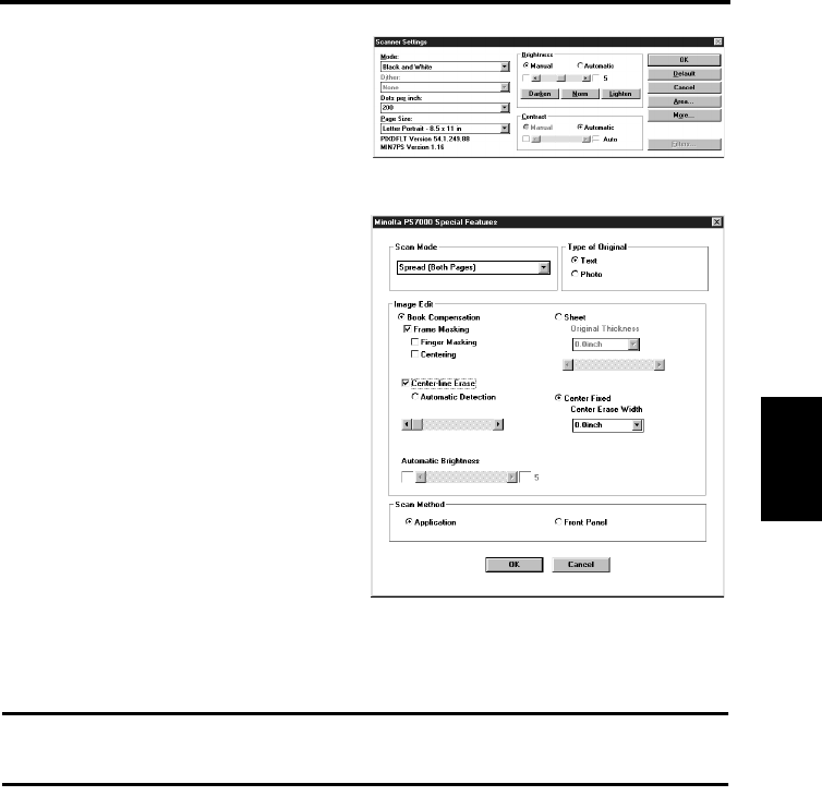
A screen with Scanner settings for
reading images appears.
Click the [More] button to show the
Special Feature setting screen.
Relevant settings on the image acquisition screen must be completed before the image is
loaded to the personal computer.
4-1
4-2
4-7
PS7000 ISIS Driver Chapter 4
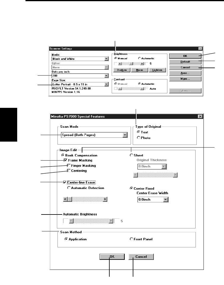
Image acquisition screen
Images can be loaded and function settings made from the personal computer using the
Image acquisition screen.
Each item is described below, with the corresponding Scanner setting indicated by a
reference page. Refer to the specified page for details.
14
17
16
7
15
8
12
13
9
10
11
3
1
5
2
6
4

Image acquisition screen
4-8
PS7000 ISIS Driver Chapter 4
1. Dot per inch: Set the resolution of the image output.
Refer to “Selecting resolution” on page 5-38 for details.
2. Paper Size: Set the size of the original to be read.
Refer to “Selecting scan size” on page 5-39 for details.
3. Brightness: Select [Automatic] or [Manual].
Brightness is adjusted manually when [Manual] is selected.
4. OK: Validates the settings.
5. Default: Initializes all the set values.
6. Cancel: Exit the image acquisition screen.
7. Scan Mode: Select [Spread] (scanning both pages), [Single] (scanning
either right or left page only), or [Book Split] (scanning right
and left pages separately).
Refer to “7. Page key” on page 2-8 for details.
8. Frame Masking: Objects outside the original are erased to prevent a
shadowed (black) frame being created in the image, i.e.
when the paper selection is larger than the original.
This function is effective only in Book mode.
Refer to “Frame Masking (Masking)” on page 5-32 for
details.
9. Finger Masking: The image of the fingers holding the original is removed
from the scanned image. This function is effective when
[Frame Masking] is selected in Book mode.
Refer to “Finger Masking (Fing Mask)” on page 5-33 for
details.
10. Centering: Any shift away from the center of the original is corrected
and the scanned image is placed in the center of the screen.
This function is effective when [Frame Masking] is selected
in Book mode.
Refer to “Centering (Centerin)” on page 5-35 for details.
11. Center-line Erase: The shadow generated in the center of the open book is
erased during scanning.
[Automatic Detection] automatically determines the center
of the original. This is effective only in Book mode.
The center of the book table is regarded as the center of
original when [Center Fixed] is selected.
The erasing range (width) can also be adjusted.
Refer to “Center Erase (Cent Erase)” on page 5-31 for
details.

Image acquisition screen
4-9
PS7000 ISIS Driver Chapter 4
12. Automatic Brightness: Brightness is adjusted automatically according to the
original when [Auto] is selected, however, further fine
adjustment is also available.
Refer to “Adjusting exposure for scanning” on page 5-36 for
details.
13. Scanning Method: To scan the document by using the application software of
your PC, set the scanning method accordingly on the
application software, and select [Application].
To scan the document by pressing either of the START keys
of the book table, set the scanning method accordingly on
the front panel, and select [Front Panel].
14. Type of Original: Select the mode (Text or Photo) suitable for the original.
Refer to “8. Image key” on page 2-8 for details.
15. Book Compensation
/Sheet: Set the type (shape) of the original.
When [Sheet] is selected, the height of the original can be
adjusted.
Refer to “Book/Sheet modes” on page 5-10 for details.
16. OK: Validates the settings.
17. Cancel: Exit the image acquisition screen.

Operation Chapter 5
Chapter 5
Operation
5-1
Operation Chapter 5
Precautions for operation
The following sections require special attention when operating the Scanner.
Do not place any object on the scanner unit.
Be careful not to knock
your head against the
scanner unit.
Do not look directly at the lamp
light visible through the front
slits or from the bottom.
Be careful not to insert your
fingers or nails into the central
part of the book table.
When only one side of the book table
is pushed down, the other side rises
slightly. Be careful not to get your
hands, fingers, or clothes caught.
Do not hold the sides when
pushing the book table down,
or your hands or fingers may
be caught. Place your hand
on the top surface of the table.
Do not stick tags, labels,
memo paper or the like
removed from the original
to the steel mirror or book
table.
Do not place any object other
than the original.
Note that reflections from wrist watches,
rings, manicures or the like may disorder
the image correction function.
The steel mirror is an important
component to read the height of the
original based on the reflections of
the top edge of the original. Do not
damage or stain the steel mirror.

5-2
Operation Chapter 5
Lamp status
Half intensity
The Scanner’s lamp lights at half intensity when any key is pressed to select menus, etc.
The lamp goes out when no key is pressed for the preset time*. The fan cooling the lamp is
turned off one minute after the lamp has gone out.
* The auto-off time for the lamp can be set to one, three, or five minutes in the Utility mode.
Full intensity
The Scanner’s lamp lights at full intensity when the Scanner is reading the original. The
lamp returns to half intensity after scanning is completed.
NOTE
The halogen lamp used in the Scanner is safe and not hazardous to health. However, never
look directly at the lamp when lit. Looking directly at the lamp when lit may result in eye
damage. When the Scanner is operated for a long time, we recommend you take a 5 minute
break every hour to rest your eyes.
5-3
Operation Chapter 5
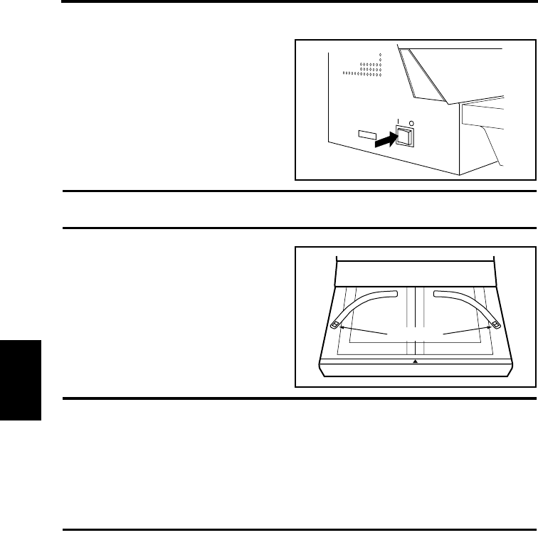
Turning the Scanner ON and OFF
Turning on
Check that the Scanner is connected
to the personal computer with the
interface cable and turn the
Scanner’s power switch on (“|”
position).
NOTE
Turn the scanner on before turning on the personal computer.
[Welcome to PS7000. Initializing]
appears on the display and the start
key turns red. The Scanner can be
operated when the start key turns
green.
NOTE
When the SCSI cable is not connected properly, Images cannot be loaded if the PC
interface cable is not connected properly.
When the message [Start Appli./Driver] appears on the display, turn the personal computer
on and start the Driver. Refer to “Start-up” on page 3-7, or 4-5 for details on starting the
Driver.
When the message [Printer is OFF. Turn Printer ON] appears on the display, change the
[Connect] setting in [Initial] to [PC] in Utility mode. Refer to page 5-47 for details.
1
Start key
2
Turning the Scanner ON and OFF
5-4
Operation Chapter 5
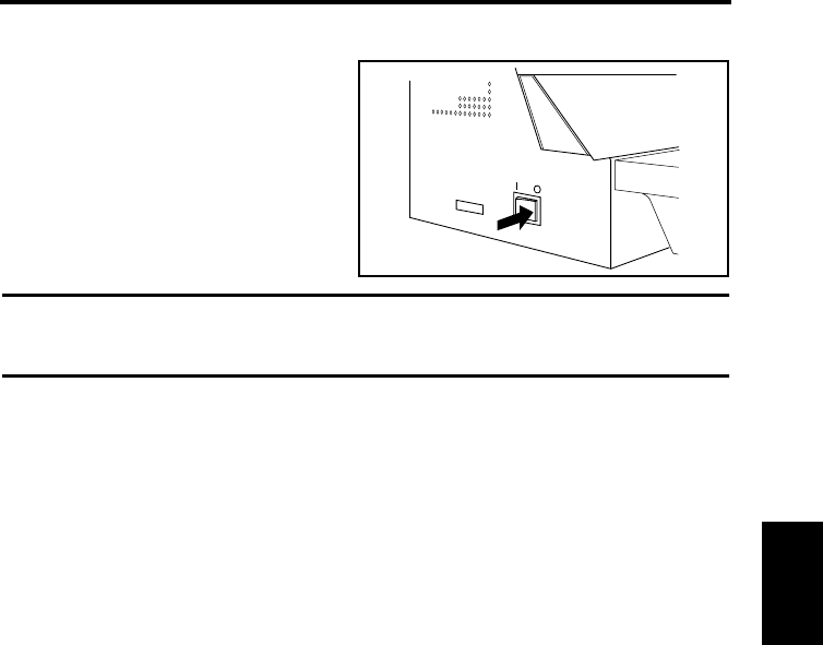
Turning off
Turn the switch off (“O” position).
NOTE
• Never turn the power switch off while the Scanner is reading the original.
• Turn off the personal computer before turning off the Scanner.
1
5-5
Operation Chapter 5
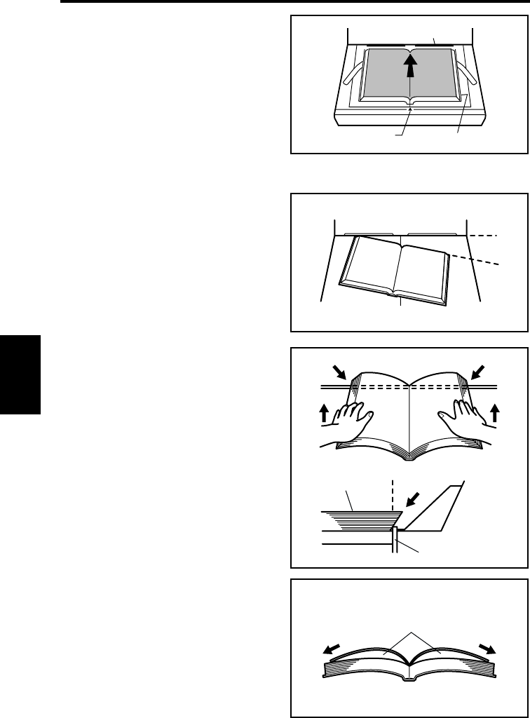
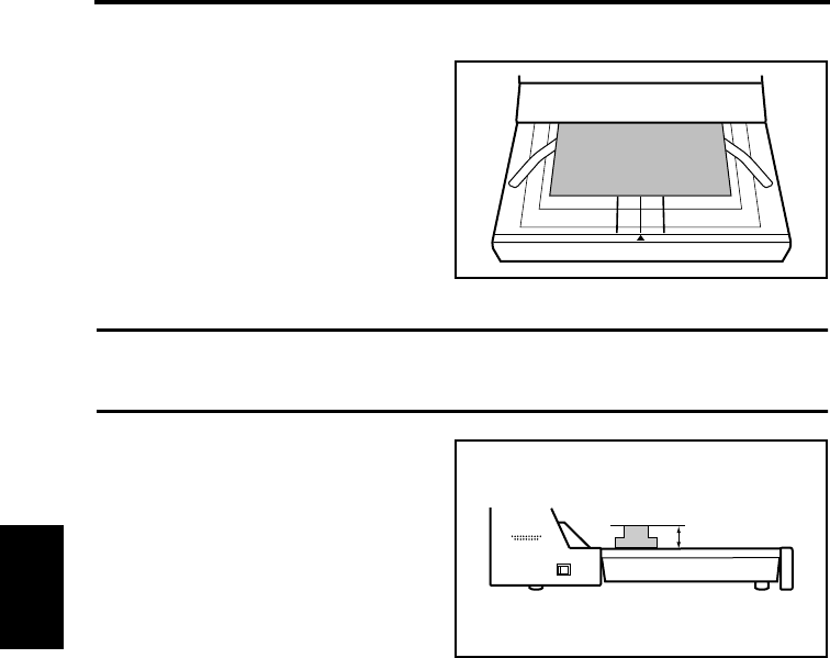
Placing the original
Place the original face up on the book
table, aligning the top edge of the book
with the stopper on the book table, and the
spine of the book with the center mark.
Check that the original is positioned with
the corresponding size guide, if possible.
When placing the original, observe the
following.
Do not place the original askew.
Do not place the original with its top
edge beyond the stopper. Be careful
that if the original is pressed at the bot-
tom first, this may happen.
When the original is spread open, be
careful not to produce openings
between pages. Press both pages and
then pull them apart.
Stopper
Center mark Size guide
Original
Stopper
Spread
5-6
Operation Chapter 5
Scanning procedures
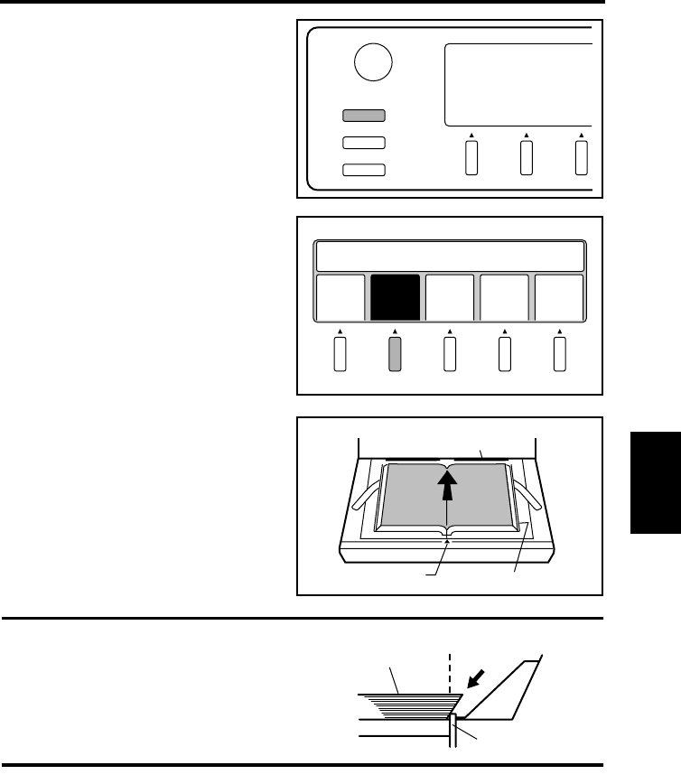
Press the User Mode key.
Select [Book/Sheet]. Select Book
when scanning a thick original
(books or dictionaries), and Sheet
when scanning a single page
document. Refer to page 5-10
“Book/Sheet modes” for details.
Place the original face up on the
book table, aligning the top edge of
the book with the stopper on the
book table, and the spine of the book
with the center mark. Check that
the original is positioned with the
corresponding size guide, if
possible.
NOTE
In placing the original, make sure that its
top edge is not beyond the stopper.
User Mode
Contrast
Job Recall
Mode Check
1
Save
Data
Book
Sheet
Cent
Eras
Out
put
Prev
ious
Set User Choice
2
Stopper
Center mark Size guide
3
Original
Stopper
Scanning procedures
5-7
Operation Chapter 5
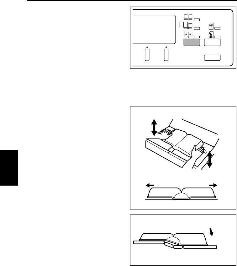
Press the Page key to specify which
page is to be scanned.
Spread:
Entire area (both pages) is scanned
as one sheet.
Single:
Only one page (right or left) is
scanned.
Book Split:
Both pages are scanned separately,
one page at a time.
The lamp of the selected mode lights.
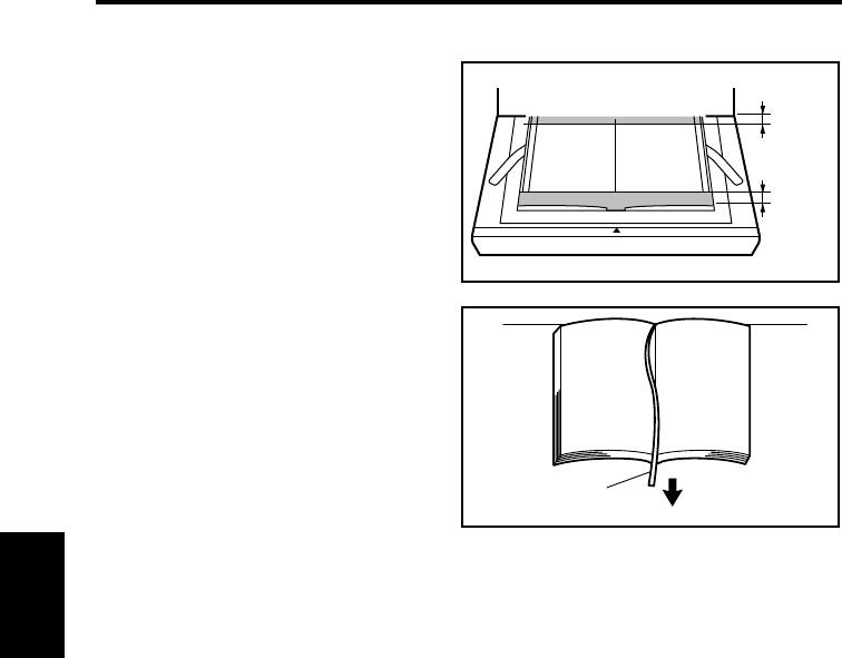
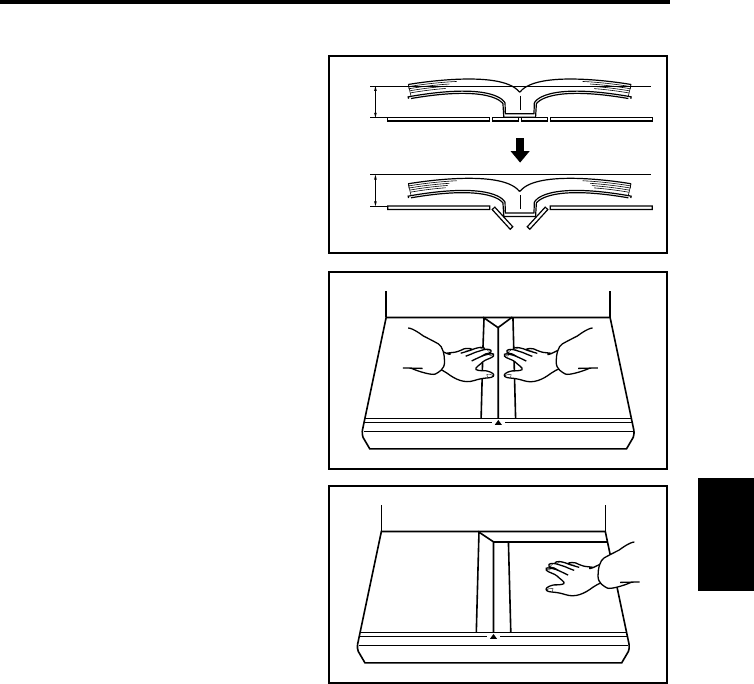
Hold the edges of both pages in the
middle with your hands, and press
the book down, pulling the pages
slightly apart.
At the same time, adjust the height
of the right and left pages by
pressing the higher side down.
Book Split
Panel Reset
Single
Photo
Text
Spread
4
5
Scanning procedures
5-8
Operation Chapter 5
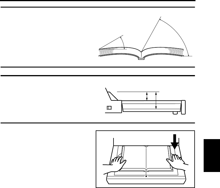
NOTE
When the inclination of the page at the
center of the book exceeds 60° and that
of the outer edge exceeds 30° (A3 or
smaller) or 10° (A2), the image cannot
be read correctly.
NOTE
Auto Focus is only effective within the
range of 65 mm above the usual height of
the book table. Adjust the book table
height so that the original is placed in
the effective Auto Focus range.
Press the Start key. Either key can be
pressed when [Spread] is selected.
When [Single] or [Book Split] is
selected, press the key on the side to
be scanned.
The pressed Start key turns red and
scanning is started. When scanning
is completed, the Start key turns
green and the next scan can be
started.
60
30 for A3 or smaller
10 for A2
65 mm 115 mm
6
Scanning procedures
5-9
Operation Chapter 5
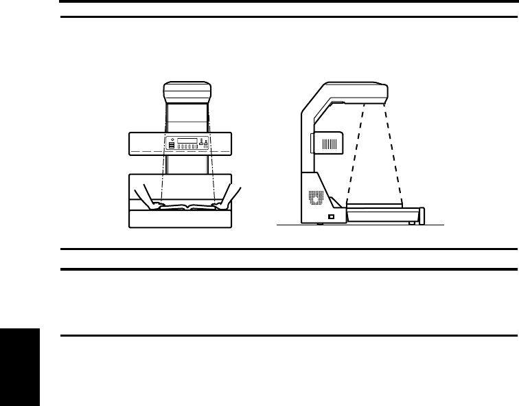
NOTE
Never place your arm, head or any other obstacle into the space enclosed by the scanner
unit and the right and left edges of the book, or the Scanner will not be able to obtain a
good image. Be sure not to move your hands and arms until scanning is completed.
NOTE
When the Scanner fails to read the original correctly, a buzzer goes off, a warning message
appears on the display, and scanning is stopped. Refer to page 6-2 “Troubleshooting for
warning messages” for the appropriate action.

5-10
Operation Chapter 5
Book/Sheet modes
Book mode
Select this mode when scanning a thick original (books). Selecting this mode automatically
activates the following functions:
Functions automatically activated
Curved text line correction
This function corrects the position of the text on the curved surface near the center of the
book (area between pages) of a thick open book, ensuring that an undistorted image is
made.
Text compression correction
The text at the center of the book (area between pages) of an open book often looks
crowded with little space between characters, when viewed from above, due to the curved
surface. If simply scanned as is, the text appears compressed. This function expands the
characters accordingly, providing an image as close as possible to the original form.
NOTE
When the text is within 5 mm from the spine of the book or the inclination at the center
exceeds 60°, proper correction may not be made.
Auto focus
This function is available only to Book mode. The original height is detected, and the focal
point of the Scanner can be adjusted to be within a range from 0 to 65 mm above the book
table according to the detected original height.
Book/Sheet modes
5-11
Operation Chapter 5
Sheet mode
Select this mode if an error message
appears or a clear image cannot be obtained
in Book mode, or when scanning thin
materials (newspapers, photographs,
documents, etc.) or a solid surface other
than a book.
NOTE
Text is selected for the Image mode by default. It is recommended that this be changed to
Photo when scanning photographs.
When Sheet mode is selected, the focal
point can be set to be within a range from 0
to 50 mm above the book table in 6 steps in
10 mm increments. When scanning a solid
surface, adjust the original (solid surface)
height in Sheet mode.
Cancel of the Auto function
In the Sheet mode, the scan time can be shortened by disabling the preliminary scanning for
auto detection. Set each function as follows to cancel the Auto function.
• Expo (Manual)
• Zoom (Fixed magnification)
• Cent Eras (OFF)
• Masking (OFF)
•Fing Mask (OFF)
• Centerin (OFF)
• Org. type (Normal or Glossy)
0 to 50 mm
5-12
Operation Chapter 5
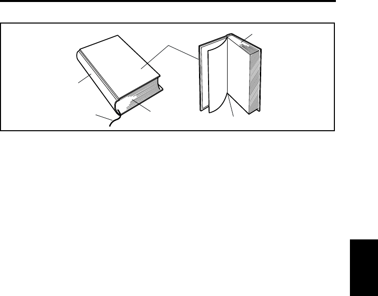
Note on originals
Name of book
1.Back
2.Tassel
3.Cover
4.Foot
5.Head
6.Guter
The Scanner is designed for exclusive use in scanning images from a book or file. Note,
however, that it may not make reliable images from any of the following types of originals.
(If a warning message appears, refer to page 6-2 “Troubleshooting for warning messages”.)
If any originals other than the following cannot be scanned, contact our service agent or
dealer in your area.
1. High-gloss originals
High quality images cannot be assured when scanning high-gloss pages such as gravures
of magazines and catalogs in Auto Exposure mode. In this case, select Manual Exposure
mode and hold the original as flat as possible. Refer to page 5-36 “Adjusting exposure for
scanning” for auto/manual exposure adjustment.
In addition, the original type may be set to [Glossy] for scanning (Refer to page 5-43
“Selecting Original Type”).
2. Originals having high background density
The background density is the color of the actual paper on which text and photographs are
printed. Papers of high background density include colored (other than white) paper,
newspaper, train timetables, or diazo scanning materials (A2 or larger drawings used at
construction sites and other engineering environments). When any of these types is used,
select Manual Exposure mode and hold the original as flat as possible.
1
2
3
4
5
6
Note on originals
5-13
Operation Chapter 5
3. Originals with a tag attached or bookmark placed
The Scanner may not work correctly
when a tag is attached or a bookmark is
placed within 1-1/8” (30 mm) of the top
and bottom edges as shown in the figure.
In this case, remove the tag or bookmark
before scanning. If tags are attached only
to the top edge of the original, place the
original upside down on the book table
for scanning.
If bookmarks are placed in the original,
put them away in the original so that
they may not hit the steel mirror.
4. Originals with both text and photographs
The Scanner provides you with two Image modes, Text and Photo. When an original has
both text and photographs, determine which should be given higher priority. When Text
mode is selected, clearer characters can be obtained.
5. Originals larger than the book table
The start key cannot be pressed when the original is larger than the book table. Use the
optional foot switch, or if the original is bound in a file, take out the required page and
place it on the book table.
6. Originals with foldings, wrinkles or warps
If the original is folded, wrinkled or warped, stretch the original as much as possible, and
then place it on the book table for scanning.
30 mm
30 mm
Bookmark
Note on originals
5-14
Operation Chapter 5
7. Originals with special binding
When the binding section of the book
has a special design and the surface of
the original is more than 65 mm above
the book table as shown in the figure,
press the center of the book table so that
the binding section is lowered to the
extent that the Auto Focus function is
effective.
Push the center of the book table with
your hands (see figure). The depth can
be adjusted to two levels.
Push down either side of the table and
release it to return the center of the book
table to its normal position.
65 mm
65 mm
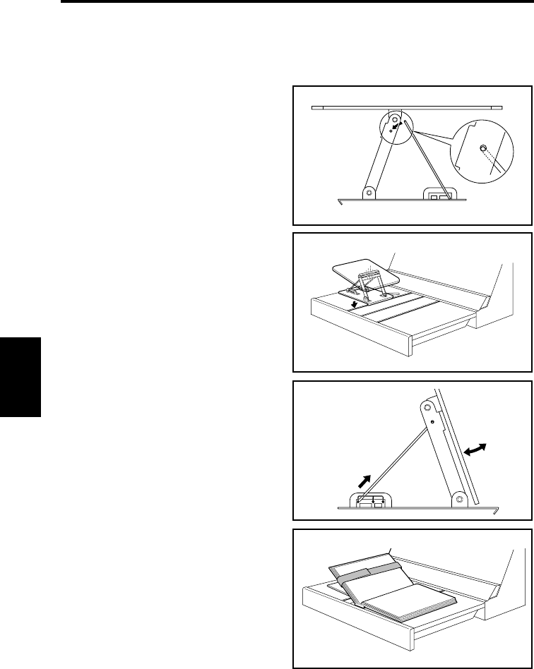
Note on originals
5-15
Operation Chapter 5
8. Books requiring special attention for the binding section
An optional angle book holder is used to fix the opening angle of the book when scanning
a valuable book whose binding must be carefully protected.
Assemble the angle book holder
as shown in the figure.
Insert the holder into the groove
on the book table.
Change the stand position to
adjust the angle of the book
holder.
Position the book and secure it to
the holder with the attached band
as shown in the figure.
1
2
3
4
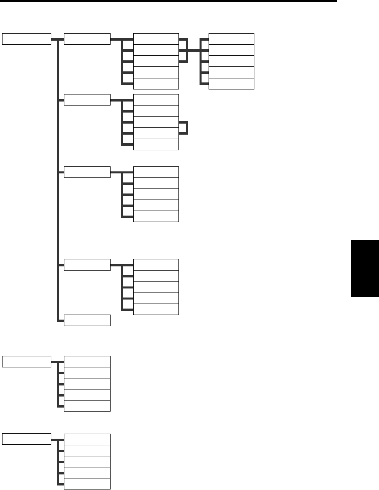
5-16
Operation Chapter 5
Menu flow chart
Pressing the keys on the control panel displays the corresponding menus as shown below.
Confirm
Previous
OK
Up to three programs of
customized settings can be
registered.
Select an external device
(printer or personal computer)
to be connected to the
Scanner.
Recalls the customized
settings previously
registered using [Program].
Displays the current settings
for the Scanner.
The shadow generated in the
center of the open book is
masked. [Auto Set] can be
selected in Book mode to
detect the center of the
original. The center of the
original is regarded as the
center of the book table when
[Cent Set] is selected. The
shadow masking width can be
set from 2.5 to 20 mm (in 2.5
mm increments).
Select Book mode when
scanning the thick original
(book), and Sheet mode when
scanning a single-page
document.
Save Data
Book Sheet
Cent Eras
Output
Previous
NO.1
NO.2
NO.3
OK
Book mode
Sheet mode
OK
(In Book mode: Set the original distance.)
(In Sheet mode: Set the original height.)
(Available only in Book mode)
Auto set
Cent set
-2.5 mm Wide
+2.5 mm Wide
OK
PC
Printer
OK
User Mode
Job Recall
Mode Check
NO.1
NO.2
NO.3
Previous
Previous
* Select [OK] to return to the main menu.
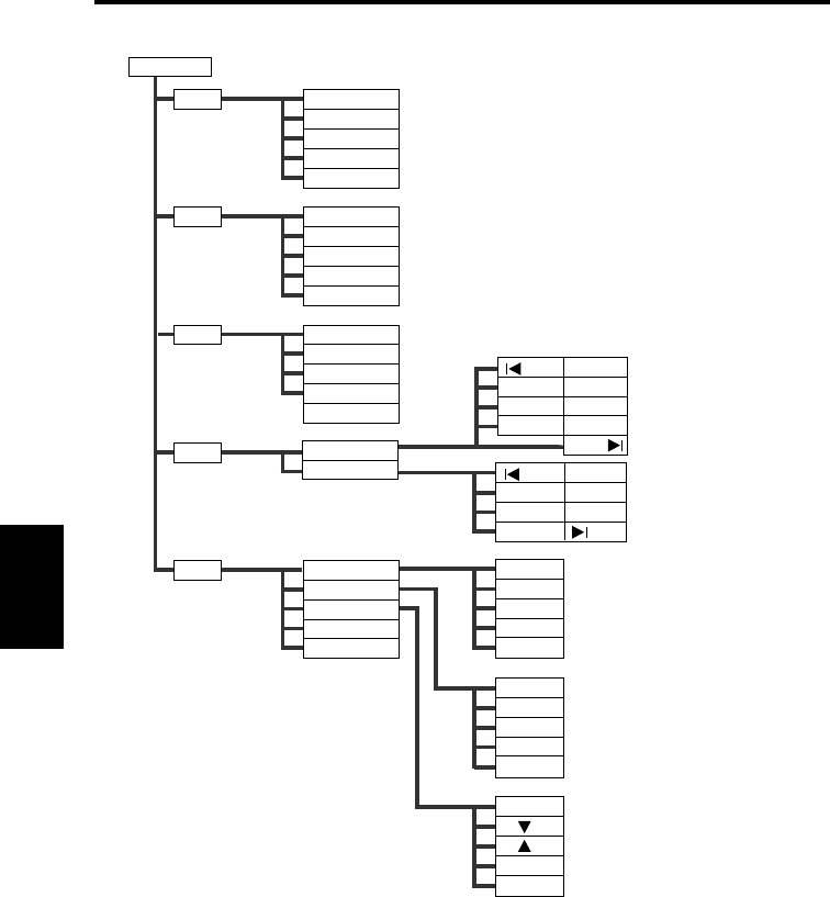
Menu flow chart
5-17
Operation Chapter 5
The following items can be set from the main menu: In Inch
O/D
-1
+1
Previous
OK
2
Gray
Previous
OK
Main Menu
Edit
Expo
Reso
Size
Qlty
Cent Eras
Masking
Fing Mask
Centerin
OK
Lite
Auto
Dark
OK
200dpi
300dpi
400dpi
600dpi
OK
Org. Type
Scale
Contrsat
OK
Turns the Center Erase,
Frame Masking, Finger
Masking, and Centering
functions on and off.
Sets exposure for scanning.
In addition to turning [Auto]
on and off, nine levels of
exposure can be selected
using [Lite] or [Dark].
Sets the resolution for the
image output.
Sets the size and direction
(portrait or landscape) of the
original to be scanned.
Sets the image Quality.
(Available only when Frame Masking is on)
(Available only when Frame Masking is on)
(Available only in Text mode)
(200/240dpi can be set.)
(Effective only when option is attached.)
Landscape
Portrait
17 X 23
14 X 22
14 X 17
11 X 17
11 X 14
LGL
LTR
H.LT
17 X 14
17 X 11
14 X 11
Auto
Normal
Grossy
Previous
OK
LGL
LTR
H.LT
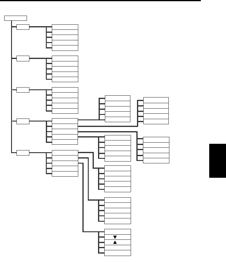
Menu flow chart
5-18
Operation Chapter 5
The following items can be set from the main menu: In Metric
Main Menu
Edit
Expo
Reso
Size
Qlty
Cent Eras
Masking
Fing Mask
Centerin
OK
Lite
Auto
Dark
OK
200dpi
300dpi
400dpi
600dpi
OK
Org. Type
Scale
Contrast
OK
Turns the Center Erase,
Frame Masking, Finger
Masking, and Centering
functions on and off.
Sets exposure for scanning.
In addition to turning [Auto]
on and off, nine levels of
exposure can be selected
using [Lite] or [Dark].
Sets the resolution for the
image output.
Sets the size and direction
(portrait or landscape) of the
original to be scanned.
Sets the scale for the image
output.
* Select [OK] to return to the main menu.
(Available only when Frame Masking is on)
(Available only when Frame Masking is on)
(Available only in Text mode)
(200/240dpi can be set.)
A2
A3
A4
A5
OK
A(Landscape)
A(Portrait)
B(Landscape)
B(Portrait)
OK
B4
B5
B6
OK
A3
A4
A5
A6
OK
B3
B4
B5
OK
O/D
-1
+1
Previous
OK
2
Gray
Previous
OK
(Effective only when option is attached.)
Auto
Normal
Grossy
Previous
OK
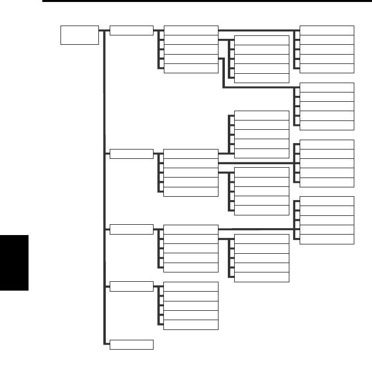
Menu flow chart
5-19
Operation Chapter 5
The following settings can be made from the main Utility screen.
Initial
Time set
SCSI set
* Select [OK] to return to the main Utility screen.
Select
Function
Initial settings are
customized and
activated for the
current and
subsequent
operations.
Timer settings are
customized and
activated for the
current and
subsequent
operations.
Detection items and
buzzer preferences
are customized and
activated for the
current and
subsequent
operations.
ID number of the
SCSI port is
customized for the
current and
subsequent
operations.
Caution
Pnl set
Connect
Reset
Previous
Auto clr
Lamp off
Save mode
Previous
Variety
Buzzer
Previous
Down
Up
Previous
OK
PC
Printer
Previous
OK
1 min.
3 min.
10 min.
No
OK
10 min.
20 min.
30 min.
OK
Alarm
Stop
Key in
No
OK
Set cfm
Previous
OK
Previous
OK
1 min.
3 min.
5 min.
OK
Orig high
Orig size
AE
Shading
OK
Main Manu
Main Manu is
desplayed.
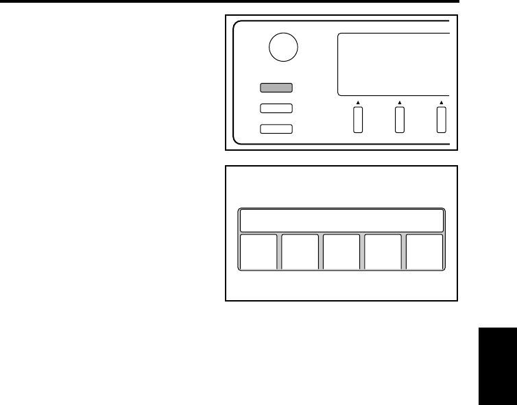
5-20
Operation Chapter 5
User Mode
Press the User Mode key on the control
panel.
The User Mode menu is displayed.
User Mode
Contrast
Job Recall
Mode Check
Save
Data
Set User Choice
Book
Sheet
Cent
Eras
Out
Put
Prev
ious
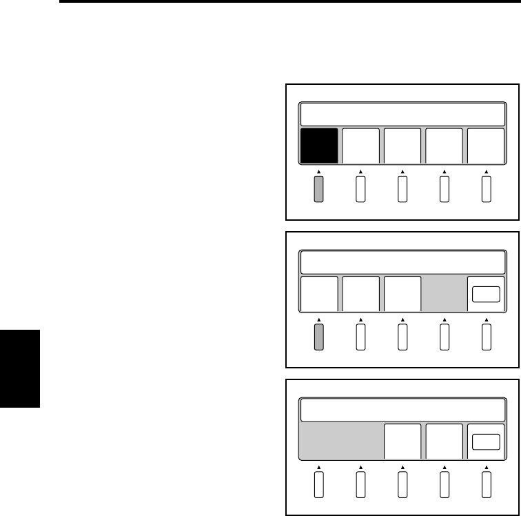
User Mode
5-21
Operation Chapter 5
Save Data
Up to three programs can be registered in No. 1 to 3. These programs can be recalled using
the Job Recall key.
Select [Save Data] from the User
Mode menu.
The program registration screen
appears.
Select anyone of No. 1 to 3. The
current settings are registered in the
selected program number and the
confirmation screen appears.
Select [OK] to return to the main
menu.
Select [OK] to register the settings.
Select [Confirm] to review the
settings.
Select [Previous] to return to the
program registration screen.
Save
Data
Book
Sheet
Cent
Eras
Out
Put
Prev
ious
Set User Choice
1
NO.1 NO.2 NO.3 OK
Save Current Settings
2
Conf
irm
Prev
ious OK
Save in NO. 1
3
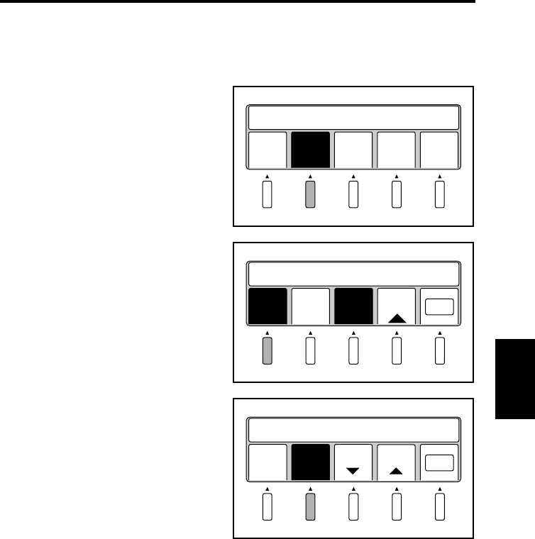
User Mode
5-22
Operation Chapter 5
Book / Sheet
Specify the type of original to be scanned. Refer to page 5-10 “Book/Sheet modes” for
details.
Select [Book/Sheet] from the User Mode
menu. The book/sheet setting screen
appears.
Select [Book mode] when scanning a thick
original (books or dictionaries).
Select [OK] to return to the main menu.
Select [Sheet mode] when scanning a sheet
original (photograph, a single-page
document, solid surface, etc.).
Select [OK] to return to the main menu.
Save
Data
Book
Sheet
Cent
Eras
Out
put
Prev
ious
Set User Choice
Book
mode
Sheet
mode OK
Set dist. to stopper (~10)
Auto +
0.5 mm
Auto
OK
Book
mode
Sheet
mode
-
10 mm
+
10 mm
Set Thickness (~50) 0
mm
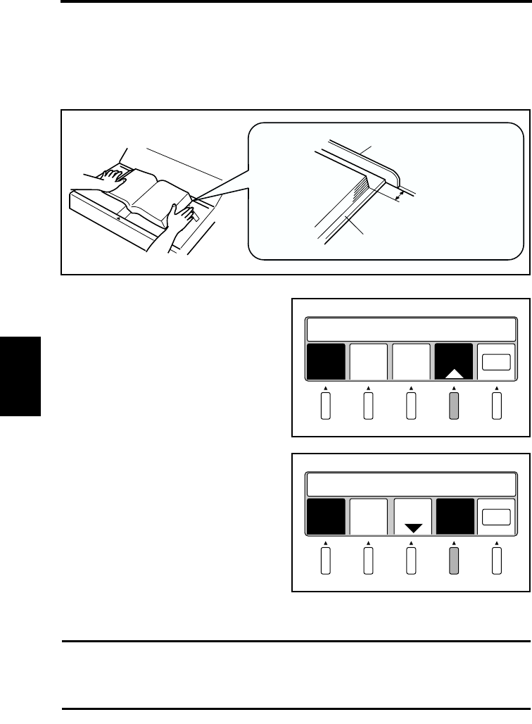
User Mode
5-23
Operation Chapter 5
Book mode setting function
Normally, “Book mode” is used in “Auto” setting.
In the following cases, however, set the distance between the stopper and the original.
◆A hardcover book is scanned
◆The original height cannot be detected (a waning message “Book Size in Not Detected”
appears)
Set the distance between the stopper and
the original by pressing allow key.
Setting value: 0 to 10 mm
Select the setting value as [0 mm] or [10
mm], [Auto] will appear again.
Then press [Auto] to return to the “Auto”
setting.
Select [OK] to return to the main menu.
NOTE
If the reliable image cannot be made or a warning message appears even though the top
edge of the book is aligned with the stopper, set the distance between the original and the
stopper to [0 mm] and retry scanning.
Stopper
Hardcover
0 to 10 mm
Book
mode
Sheet
mode OK
Set dist. to stopper (~10)
Auto
0.0 mm
+
0.5 mm
Book
mode
Sheet
mode OK
Set dist. to stopper (~10)
Auto
0.0 mm
-
0.5 mm
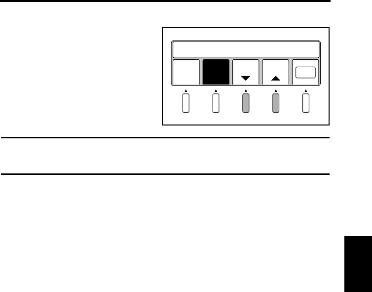
User Mode
5-24
Operation Chapter 5
Sheet mode setting function
Only in Sheet mode, the setting value of the
original height can be adjusted to be within
a range of 0 to 50 mm in 10 mm
increments. The adjusted setting value
appears on the display.
Select [OK] to return to the main menu.
NOTE
When Sheet mode is selected, the position setting for Center Erase is changed from [Auto]
to [Center].
Book
mode
Sheet
mode OK
Set Thickness (~50) 20
mm
-
10 mm
+
10 mm
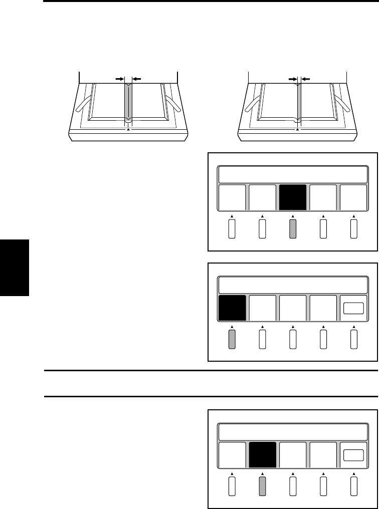
User Mode
5-25
Operation Chapter 5
Center Erase
The shadow generated in the center of the open book is removed.
Select [Cent Eras] from the User Mode
menu. The center eras setting screen
appears.
Select [Auto set] to detect the reference
position for erasing automatically.
Select [OK] to return to the main menu.
NOTE
[Auto set] cannot be selected in Sheet mode.
Select [Cent set] to fix the center of the
book table as the reference position for
erasing.
Select [OK] to return to the main menu.
Spread mode
Erasing width
Single or Book Split mode
Erasing width
Save
Data
Book
Sheet
Cent
Eras
Out
put
Prev
ious
Set User Choice
Auto
set
Cent
set
Set Width/Position
-
2.5 mm
Wide
+
2.5 mm
Wide OK
Auto
set
Cent
set OK
-
2.5 mm
Wide
+
2.5 mm
Wide
Set Width/Position
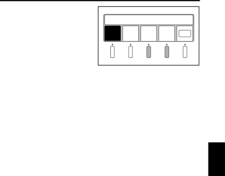
User Mode
5-26
Operation Chapter 5
The erasing width can be adjusted from 2.5
to 20 mm (0.1” to 0.8”) in 2.5 mm (0.1”)
increments. The set value is displayed in
the message area.
Select [OK] to return to the main menu.
Cent
set OK
Auto
set
-
2.5 mm
Wide
+
2.5 mm
Wide
Set Width/Position
5.0 mm
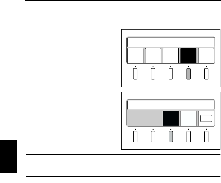
User Mode
5-27
Operation Chapter 5
Output
Select the external device connected to the Scanner.
Select [Output] from the User Mode menu.
The output setting menu appears.
Select [PC] when a personal computer is
connected.
Select [OK] to return to the main menu.
NOTE
A dedicated printer and optional PR interface kit are required to connect a printer. Contact
your authorized dealer.
Save
Data
Set User Choice
Book
Sheet
Cent
Eras
Out
put
Prev
ious
PC Prin
ter OK
Set Output Device
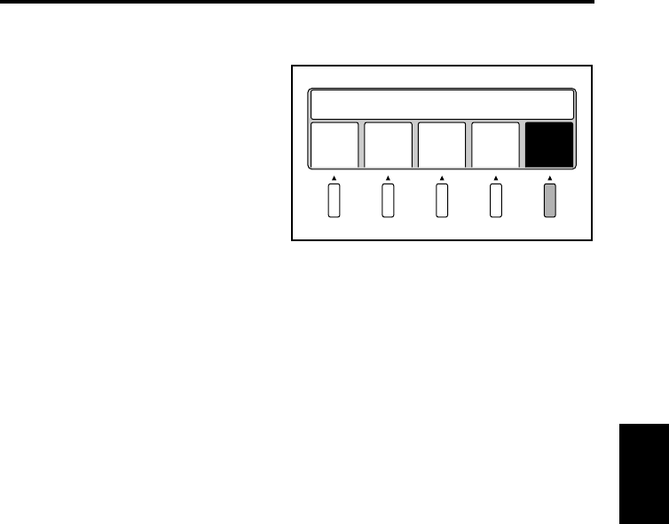
User Mode
5-28
Operation Chapter 5
Exiting User Mode
Select [Previous] from the User Mode
menu.
Save
Data
Book
Sheet
Cent
Eras
Out
put
Prev
ious
Set User Choice
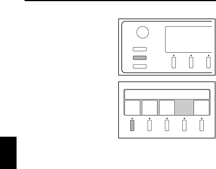
5-29
Operation Chapter 5
Recalling jobs
Recall programs registered using [Save Data].
Press the Job Recall key on the
control panel.
Select anyone of programs No. 1 to 3.
The corresponding program is
recalled and validated.
Select [Previous] to return to the
previous screen.
User Mode
Contrast
Job Recall
Mode Check
1
NO.1
Recall Settings
NO.2 NO.3 Prev
ious
2
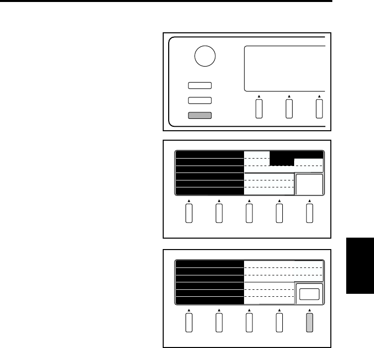
5-30
Operation Chapter 5
Checking current settings
Current settings can be checked.
Press the Mode Check key on the control
panel. This key can be used to check
settings whenever necessary.
Current settings are displayed.
Select [Next]. The following screen
appears.
Select [OK] to return to the main menu.
User Mode
Contrast
Job Recall
Mode Check
Next
ORIGINAL
FRAME MASK CENTERING
FINGER MASK
CENTER ERASE
CONNECTION
ON
OFF
Book Auto
PC
OFF
OFF
ORIG.TYPE Auto
OK
CONTRAST Highlight
Shadow 0
0
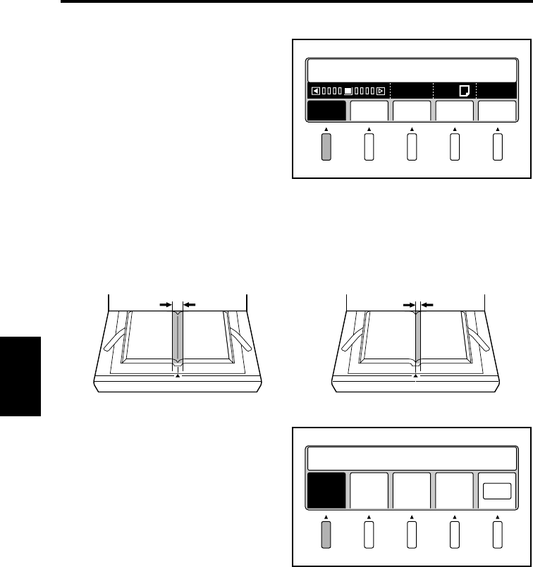
5-31
Operation Chapter 5
Using the edit functions
Edit Functions
Select [Edit] from the main menu to set
editing functions for scanning.
Center Erase (Cent Eras)
The shadow generated in the center of the open book is erased during scanning.
Select [Cent Eras]. The menu name is
highlighted and the function is activated.
Select [OK] to return to the main menu.
Edit Expo
Start Appli./Driver
Reso QltySize
A600
2
A4
Spread mode
Erasing width
Single or Book Split mode
Erasing width
Cent
Eras
Mask
ing
Fing
Mask
Cent
erin OK
Set Image Edit
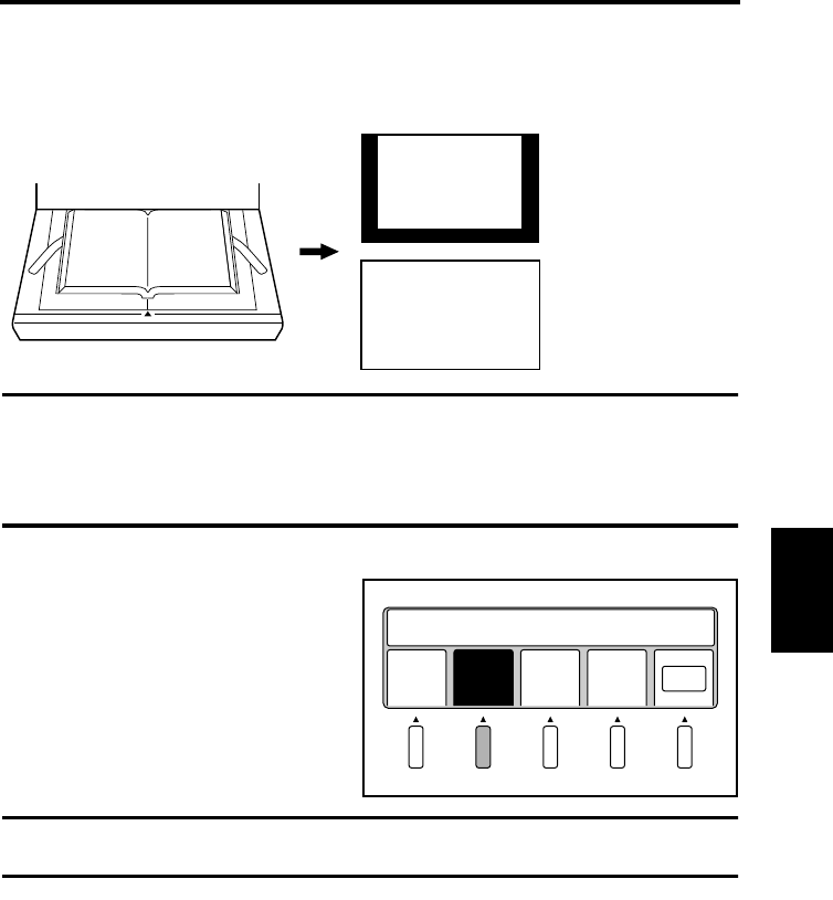
Using the edit functions
5-32
Operation Chapter 5
Frame Masking (Masking)
Objects outside the original are erased to prevent a shadowed (black) frame from being
created on the output, i.e. when the selected paper is larger than the original.
NOTE
• This function is not effective when an image exists within 2 mm of the edge of the
original.
• Frame Masking may affect scanning depending on the density and colors of the original.
When any portion of the required image is erased, turn off Frame Masking.
Select [Masking]. The menu name is
highlighted and the function is activated.
Select [OK] to return to the main menu.
NOTE
Frame Masking must be on to turn on Finger Masking and Centering.
Frame Masking: OFF
Frame Masking: ON
12
12
12
Cent
Eras
Set Image Edit
Mask
ing
Fing
Mask
Cent
erin OK
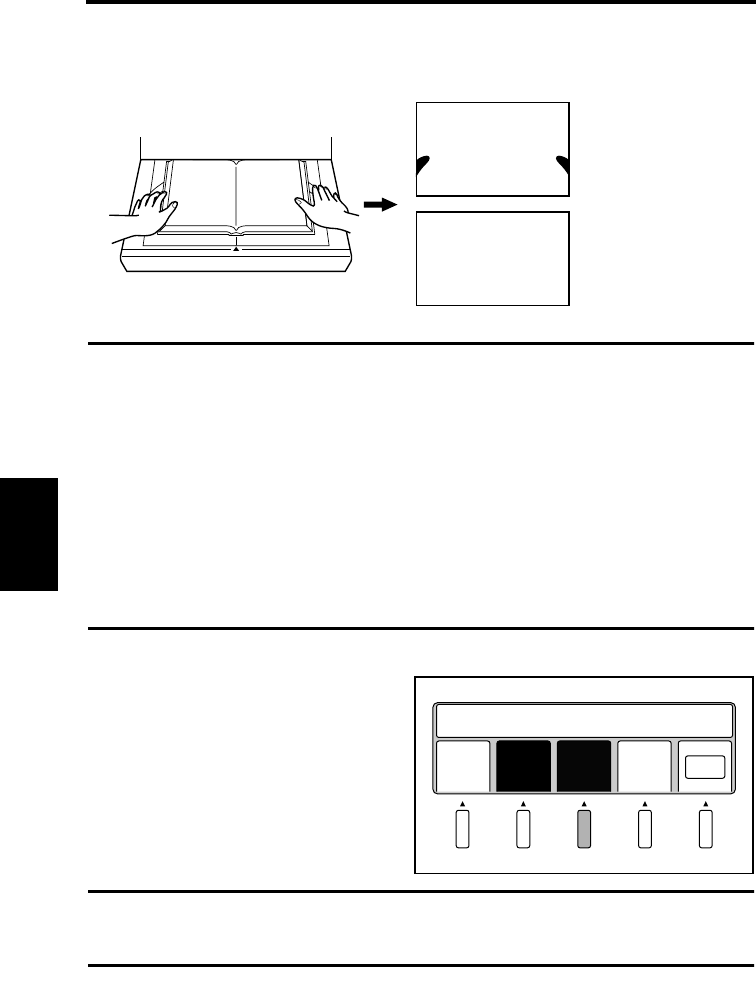
Using the edit functions
5-33
Operation Chapter 5
Finger Masking (Fing Mask)
This function removes the image of the fingers holding the original from the scanned image.
NOTE
Finger Masking may affect scanning depending on the density and colors of the original.
When any portion of the required image is erased, turn off Finger Masking.
Finger Masking is not effective when;
• a finger is not placed on the original,
• a finger is placed further than 10 cm inside the edge of the original,
• a finger is closer to the center than the edge, even when the distance from the edge of
the original is less than 10 cm,
• a finger is placed on the bottom edge of the original, or
• a finger is placed within 3cm of the top edge of the original
• The original contains an image (photograph) and a finger is placed within 3 mm from
this image,
Select [Fing Mask]. The menu name is
highlighted and the function is activated.
Select [OK] to return to the main menu.
NOTE
Finger Masking cannot be activated when Frame Masking is off.
Finger Masking is canceled automatically when Frame Masking is turned off.
Finger Masking: OFF
Finger Masking: ON
12
1
12
2
Cent
Eras
Mask
ing
Fing
Mask
Cent
erin OK
Set Image Edit
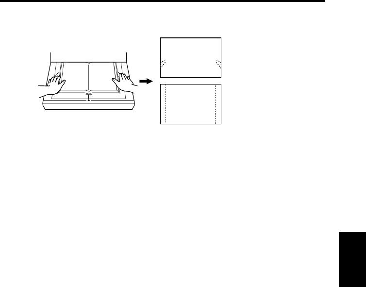
Using the edit functions
5-34
Operation Chapter 5
Finger Masking is available in the following 2 modes.
Default setting is “Masking fingers only.”
To change the setting, contact your authorized dealer.
Masking fingers only
Masking outer margins
(Including fingers)
12
1
12
2
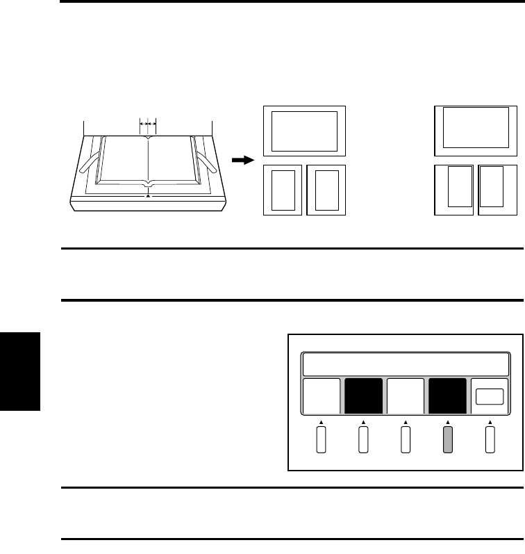
Using the edit functions
5-35
Operation Chapter 5
Centering (Centerin)
Any shift away from the center of the original is corrected and the scanned image is placed
in the center of the screen.
NOTE
This function is not effective when the center of the original is shifted 30 mm or more from
the center of the book table.
Select [Centerin]. The menu name is
highlighted and the function is activated.
Select [OK] to return to the main menu.
NOTE
Centering cannot be activated when Frame Masking is off.
Centering is canceled automatically when Frame Masking is turned off.
Spread mode
Centering: ON
Single or Book
Split mode
1
30 mm 30 mm
2
12
12
Centering: OFF
12
12
Cent
Eras
Mask
ing
Fing
Mask
Cent
erin OK
Set Image Edit
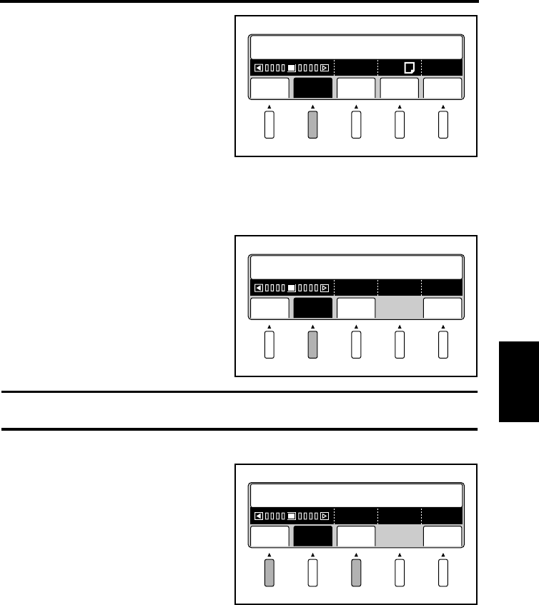
5-36
Operation Chapter 5
Adjusting exposure for scanning
Select [Expo] (exposure) from the main
menu to set the exposure for scanning.
Auto
The appropriate exposure is automatically selected according to the type of original.
Select [Auto]. The menu name is
highlighted and the function is activated.
When [Auto] is selected, “A” (Auto) is
displayed in the center of the exposure
level bar.
Select [OK] to return to the main menu.
NOTE
[Auto] cannot be selected in Photo mode.
The exposure can be further adjusted after
[Auto] is set. Press the [Lite] or [Dark] key
for fine adjustment.
Select [OK] to return to the main menu.
Edit Expo Reso QltySize
A600
2
A4
Start Appli./Driver
Lite Auto Dark OK
A
Set Exposure
Lite
Set Exposure
Auto Dark OK
A
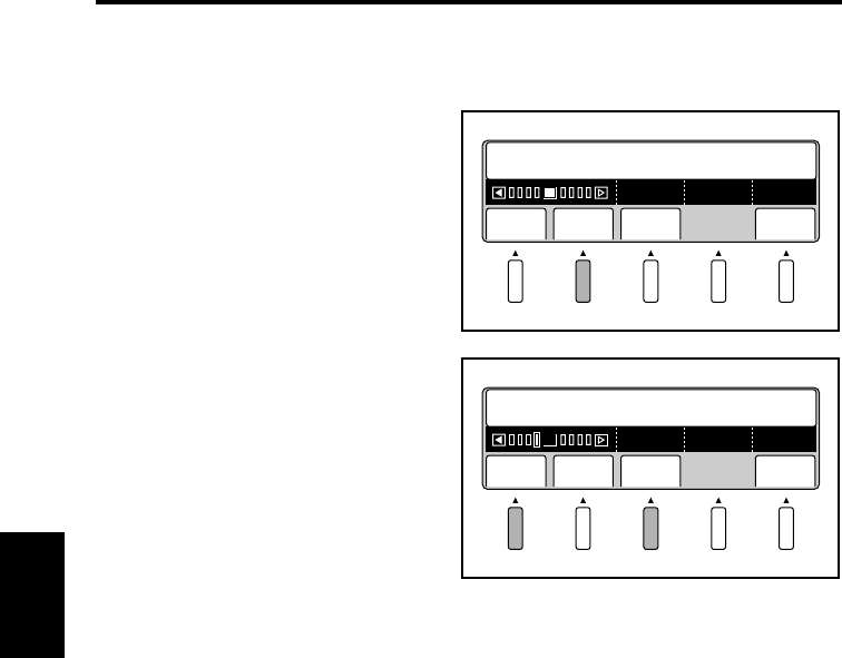
Adjusting exposure for scanning
5-37
Operation Chapter 5
Manual adjustment
The exposure for scanning is set manually.
Select [Auto] to return the menu name to
normal, indicating [Auto] is turned off.
“A” disappears from the center of the
exposure level bar.
Select [OK] to return to the main menu.
Press the [Lite] or [Dark] key to set the
exposure for scanning.
Select [OK] to return to the main menu.
Lite Auto Dark OK
Set Exposure
Lite Auto Dark OK
Set Exposure
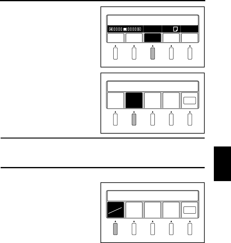
5-38
Operation Chapter 5
Selecting resolution
Select [Reso] from the main menu to set
the resolution of the image output.
Select [200 dpi], [300 dpi], [400 dpi], or
[600 dpi]. The specified resolution is
highlighted.
Select [OK] to return to the main menu.
NOTE
[600 dpi] cannot be selected when the following scan size.
landscape:A2, B3 or 17x23, 14x22, 14x17
portrait: A3, B4 or 14x17, 11x17, 11x14, LGL
The output resolution of 240dpi can be
additionally set.
For this setting, consult with your local
authorized dealer.
When 240dpi is set to be available, the
[200] key is switched to the [200/240] key.
The output resolution is switched between
200dpi and 240dpi whenever the [200/240]
key is pressed.
Edit Expo Reso QltySize
A600
2
A4
Start Appli./Driver
200
dpi
300
dpi
400
dpi
600
dpi OK
Set Resolution
200
240
300
dpi
400
dpi
600
dpi OK
Set Resolution 240 dpi
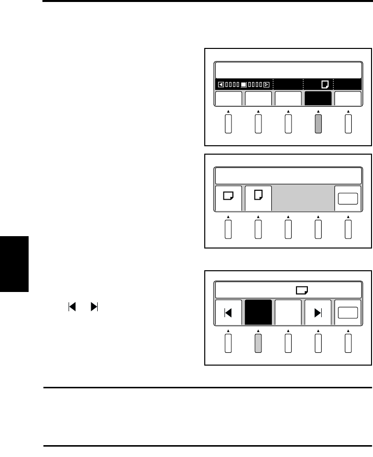
5-39
Operation Chapter 5
Selecting scan size
The size and direction (portrait or landscape) of the original on the book table are set.
Scan size in inch
Select [Size] in the main menu.
Select original direction (landscape
or portrait).
If landscape is selected, paper size
setting screen is displayed.
Select the paper size with
or key.
Select [OK] to return to the main
menu.
NOTE
• The resolution changes from [600 dpi] to [400 dpi] when [17x23], [14x22] or [14x17] is
selected.
• The Scan mode changes from [Single] or [Book Split] to [Spread] when except [LTR]
and [H.LT] are selected.
Edit Expo Reso QltySize
A600
2
LTR
Start Appli./Driver
1
OK
Set Scan Size
2
OK
11 x 14
Select Size from
11 x 17
3
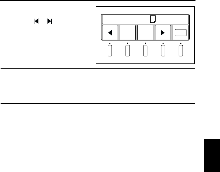
Selecting scan size
5-40
Operation Chapter 5
If portraits selected, paper size setting
screen is displayed. Select the paper
size with or key.
Select [OK] to return to the main
menu.
NOTE
• The resolution changes from [600 dpi] to [400 dpi] when [14x17], [11x17], [11x14] or
[LGL] is selected.
• The Scan mode changes from [Single] or [Book Split] to [Spread] when [17x14] is
selected.
LTR OK
H.LT
Select Size from
4
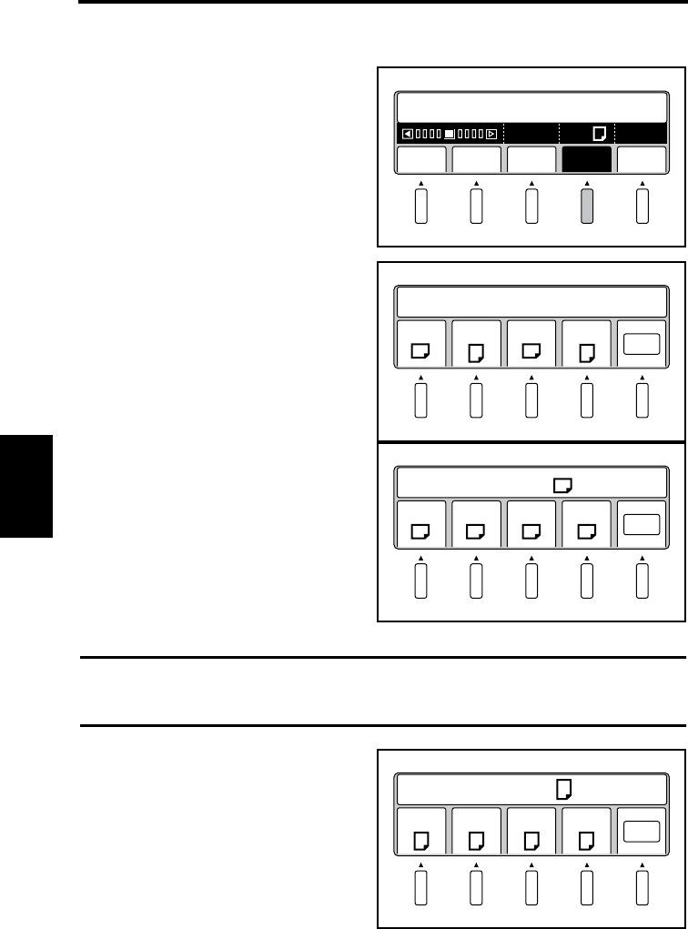
Selecting scan size
5-41
Operation Chapter 5
Scan size in metric
Select [Size] from the main menu.
Select the size (A or B) and direction
(portrait or landscape) appropriate for
the original.
Select [OK] to return to the main
menu.
When [A (Landscape)] is selected,
the size can be selected from A2, A3,
A4, and A5. The selected menu
name is highlighted.
Select [OK] to return to the main
menu.
NOTE
• The resolution changes from [600 dpi] to [400 dpi] when [A2] is selected.
• The Scan mode changes from [Single] or [Book Split] to [Spread] when [A2] is selected.
When [A (Portrait)] is selected, the
size can be selected from A3, A4, A5,
and A6. The selected menu name is
highlighted.
Select [OK] to return to the main
menu.
Edit Expo Reso QltySize
A600
2
A4
Start Appli./Driver
1
A A B B
OK
Set Scan Size
2
A2 A3 A4 A5 OK
Select Size from A
3-1
A3 A4 A5 A6 OK
Select Size from A
3-2
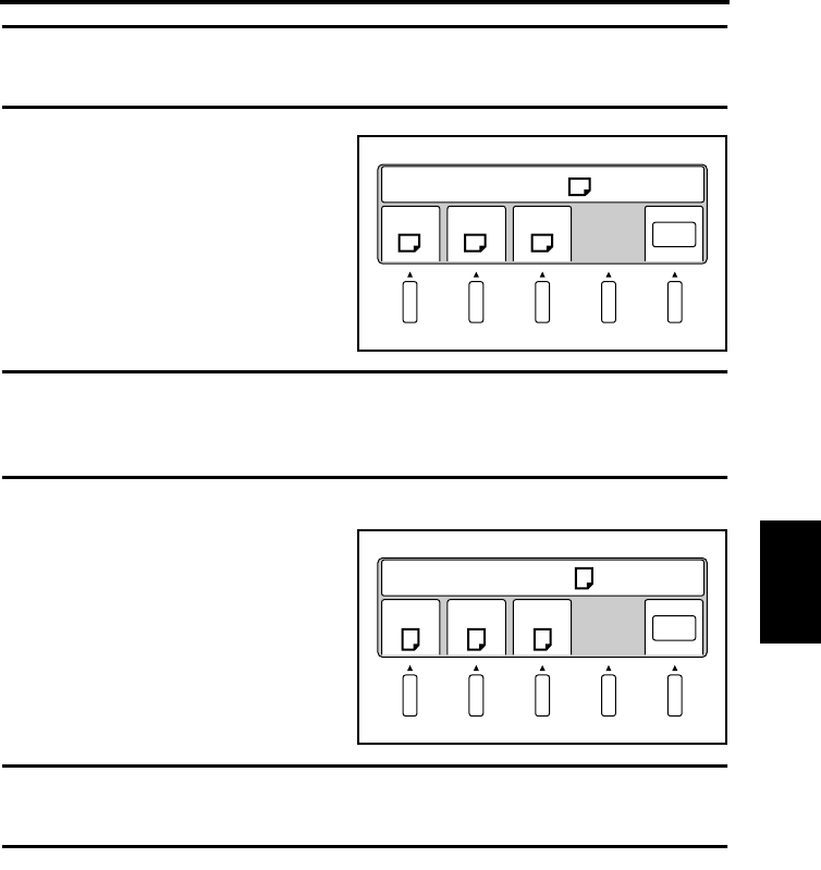
Selecting scan size
5-42
Operation Chapter 5
NOTE
• The resolution changes from [600 dpi] to [400 dpi] when [A3] is selected.
• The Scan mode changes from [Spread] to [Single] when [A6] is selected.
When [B (Landscape)] is selected,
the size can be selected from B3, B4,
and B5. The selected menu name is
highlighted.
Select [OK] to return to the main
menu.
NOTE
• The resolution changes from [600 dpi] to [400 dpi] when [B3] is selected.
• The Scan mode changes from [Single] or [Book Split] to [Spread] when [B3] or [B4] is
selected.
When [B (Portrait)] is selected, the
size can be selected from B4, B5, and
B6. The selected menu name is
highlighted.
Select [OK] to return to the main
menu.
NOTE
• The resolution changes from [600 dpi] to [400 dpi] when [B4] is selected.
• The Scan mode changes from [Spread] to [Single] when [B6] is selected.
B3 B4 B5 OK
Select Size from B
3-3
B4 B5 B6 OK
Select Size from B
3-4
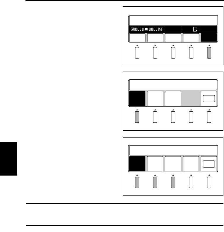
5-43
Operation Chapter 5
Selecting Original Type
Select [Qlty] in the main menu.
Select [Org. type]. The menu name is
highlighted and the original type
setting screen is displayed.
Set the original type in the original
type setting screen.
NOTE
Normally set the original type to [Auto]. For originals from which image cannot be clearly
scanned, set the original type to [Normal] or [Glossy].
Edit Expo Reso QltySize
A600
2
A4
Start Appli./Driver
1
Org.
type
Scale Cont
rast OK
Set Image Condition
2
Auto
Set Orginal Type
Norm
al
Glos
sy
Prev
ious OK
3
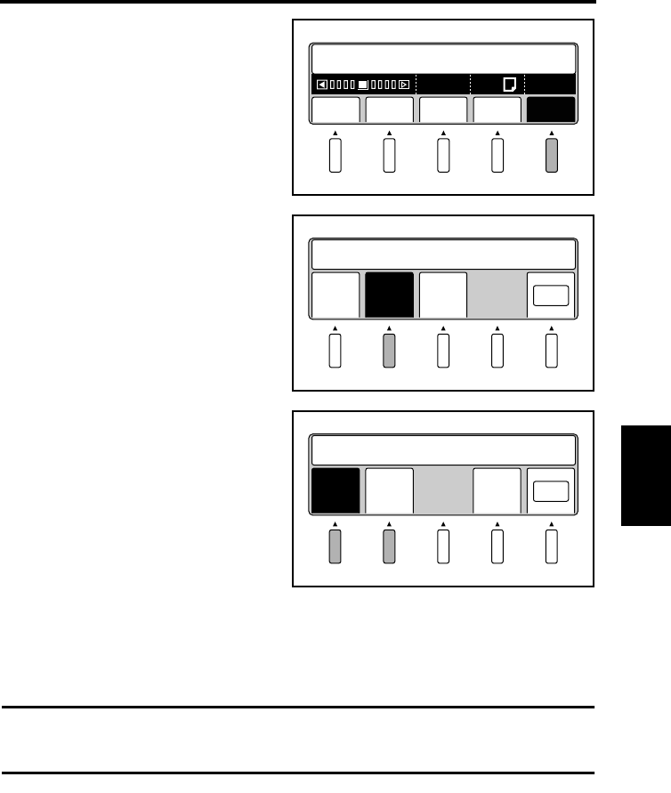
5-44
Operation Chapter 5
Selecting Output Scale
Select [Qlty] in the main menu.
Press the [Scale] key. The display is
reversed, and the Scale Setting screen
is displayed.
Select [2] or [Gray] on the Scale
Setting screen, and press the [OK]
key.
2 (Binary) : Suitable to the text original.
Read in a black and white image with high contrast.
Gray (Grayscale) : Suitable to the photo original.
Read in the image with 8-bit data.
NOTE
When the Book Scanner is not equipped with the Grayscale Memory Board (option),
[Gray] is not displayed.
Edit Expo Reso QltySize
A600
2
A4
Start Appli./Driver
1
Org.
type
Scale Cont
rast OK
Set Image Condition
2
2
Set Orginal Scale
Gray Prev
ious OK
3
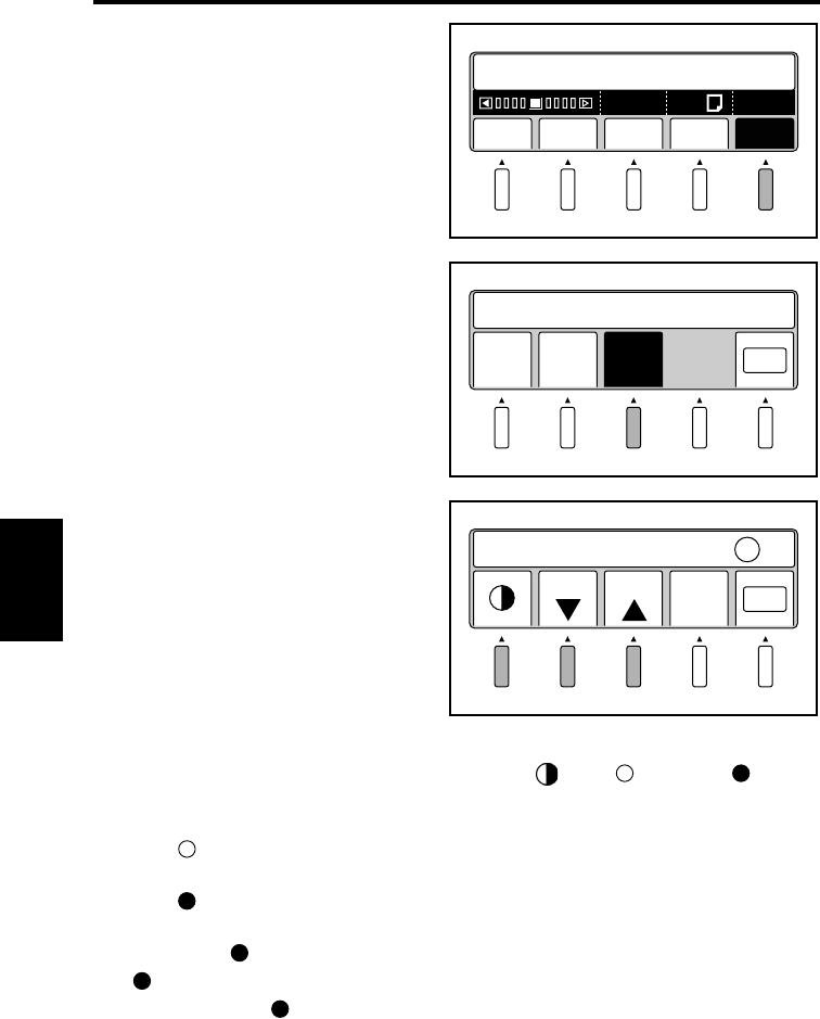
5-45
Operation Chapter 5
Selecting Contrast
Select [Qlty] in the main menu.
Select [Contrast]. The menu name is
highlighted and the original type
setting screen is displayed.
Set the contrast on the Contrast
Setting screen.
Select the part of the image to be adjusted by using the [ ] key ( : Highlight, :
Shadow), and adjust the level by using the [+] and [-] keys (Highlight: 0 to 15, Shadow: -7
to +7)
When the (Highlight) value is increased in the [+] direction, the light part becomes
lighter and at the same time the dark part becomes slightly lighter.
When the (Shadow) value is increased in the [+] direction, the dark part becomes darker.
When it is set to the [-] side, the dark part becomes lighter.
By adjusting the (Shadow) part, the light part can be slightly darkened or lightened.
The (Shadow) part may not have the effect in the plus direction.
In this case, when the (Shadow) part is set to [Dark], darker expression is possible.
Edit Expo Reso QltySize
A600
2
A4
Start Appli./Driver
1
Org.
type
Scale Cont
rast OK
Set Image Condition
2
Set Contrast +1
-1 +1 Prev
ious OK
3
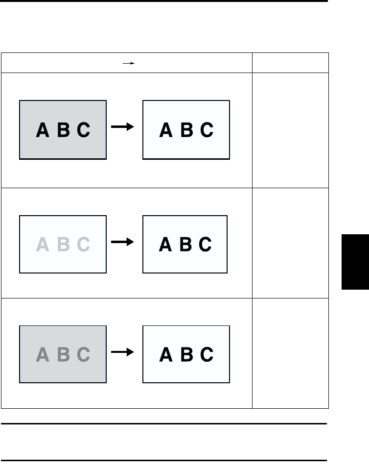
Selecting Contrast
5-46
Operation Chapter 5
The following examples describe how to adjust the image read according to the standard
settings (Highlight: 0, Shadow: 0, Exposure: Center) by correcting the contrast or adjusting
the exposure:
NOTE
The image read result may be slightly different depending on the type of the original and the
environment in which the original is read.
Image before adjusting the contrast Image after adjusting the contrast
Setting example:
To whiten the ground Highlight: +9
Shadow: +2
Exposure: Center
To darken the text Highlight: 0
Shadow: +7
Exposure: Darken
To whiten the ground and darken the text Highlight: +7
Shadow: +7
Exposure: Darken
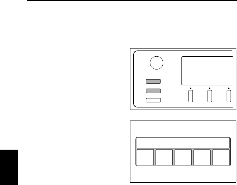
5-47
Operation Chapter 5
Operations in Utility mode
The following items can be set in Utility Mode:
• Initial settings upon power supply
• Timers (automatic clear, lamp off, and printer power save)
• Warning (detection items and buzzer preferences)
• Changing the SCSI port and ID No.
Simultaneously press the User Mode key
and the Job Recall key on the control
panel.
The main Utility screen appears.
User Mode
Contrast
Job Recall
Mode Check
Init
ial
Time
set
Caut
ion
SCSI
set
Main
Menu
Select Function
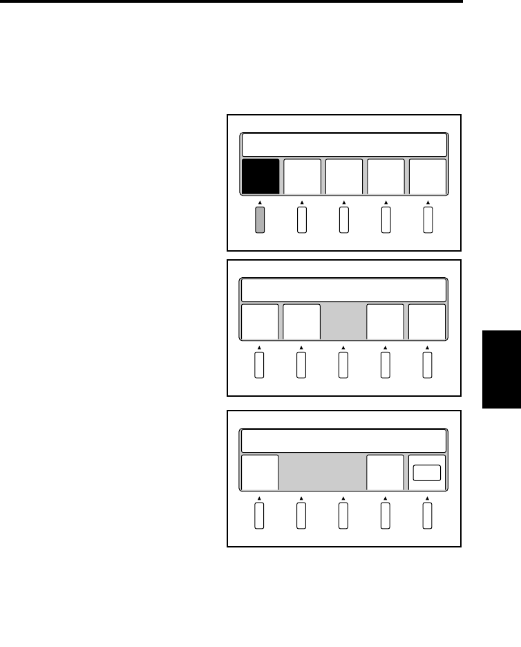
Operations in Utility mode
5-48
Operation Chapter 5
Initial settings
The initial settings (settings on the panel and the connected device) are customized and/or
reset to the default factory settings. If any of the initial settings is changed, turn off the
power to the Scanner. Then, turn it on, and the initial settings have been changed
accordingly.
Select [Initial] on the main Utility
screen. The initial setting screen
appears.
Select the desired item. The specified
menu name is highlighted.
Select [Previous] to return to the
main Utility screen.
Select [Pnl set] to check and make
the current settings the default
settings for the current and
subsequent operations.
Select [Set cfm] to check the current
settings.
Select [Previous] to return to the
previous screen.
Select [OK] to define the current
settings as the default settings for the
current and subsequent operations.
Init
ial
Time
set
Caut
ion
SCSI
set
Main
Menu
Select Function
1
Pnl
set
Conn
ect
Re
set
Prev
ious
Enable Default Settings
2
Set
cfm
Prev
ious
Save Default Panel Settings
OK
3-1
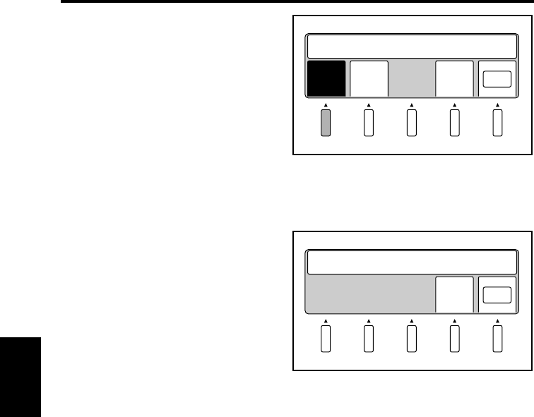
Operations in Utility mode
5-49
Operation Chapter 5
Select [Connect] to set the connected
device for the current and subsequent
operations.
Select [PC] or [Printer] to connect the
scanner to a personal computer or
printer respectively.
Select [Previous] to return to the
previous screen.
Select [OK] to define the device to
which the Scanner is connected.
Select [Reset] to reset all customized
initial settings to the default factory
settings. What can be reset here are
the setting value in the utility mode
and the registered program contents.
Select [Previous] to return to the
previous screen.
Select [OK] to define the default
factory settings for the current and
subsequent operation.
Prin
ter
Prev
ious
Save Default Ext.Device
OK
PC
3-2
Prev
ious
Reset Default.OK ?
OK
3-3
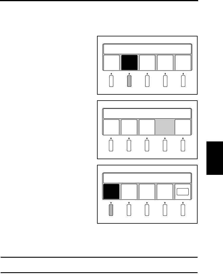
Operations in Utility mode
5-50
Operation Chapter 5
Time Set
The settings for the timer (automatic clear time, lamp off time, and printer power save time)
are set.
Select [Time set] on the main Utility
screen. The timer setting screen
appears.
Select the desired item. The specified
menu name is highlighted.
Select [Previous] to return to the
main Utility screen.
Select [Auto clr] to determine the
time until all settings are reset to the
default factory settings (auto clear
time).
Select [1 min], [3 min], or [10 min]
for the auto clear time.
Selecting [No] sets the auto clear
time to “0” and deactivates the auto
clear function.
Select [OK] to define the setting.
NOTE
When the main body is connected to the PC, the auto clear does not work.
Init
ial
Time
set
Caut
ion
SCSI
set
Main
Manu
Select Function
1
Auto
clr
Lamp
off
Save
mode
Prev
ious
Enable Timer Settings
2
1
min.
10
min.
No
Save Auto Clear Timer
OK
3
min.
3-1
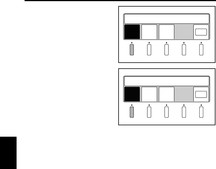
Operations in Utility mode
5-51
Operation Chapter 5
Select [Lamp off] to set the time until
the lamp is turned off (lamp off time)
after scanning has been completed, or
after the last key has been pressed.
Select [1 min.], [3 min.], or [5 min.]
to set the desired lamp off time.
Select [OK] to define the setting.
Select [Save mode] to set the time
until the printer enters Sleep mode
after printing has been completed
(printer power save time).
Select [10 min.], [20 min.], or [30
min.] to set the desired time setting.
Select [OK] to define the setting.
1
min.
5
min.
Save Auto Lamp OFF Timer
OK
3
min.
3-2
20
min.
30
min.
Save PowerSaving Timer
OK
10
min.
3-3
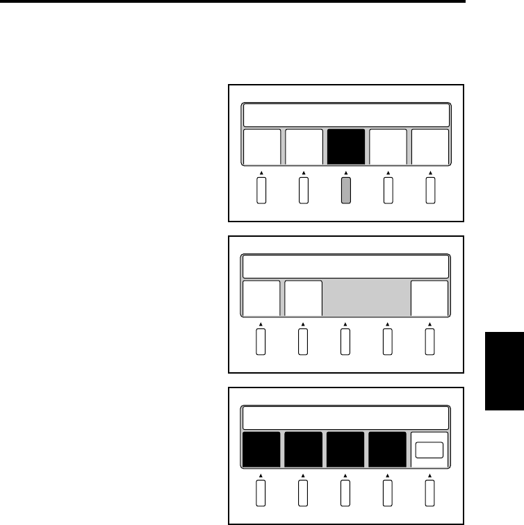
Operations in Utility mode
5-52
Operation Chapter 5
Caution
The type of detection items and buzzer preferences are set here.
All settings defined here become effective immediately.
Select [Caution] on the main Utility
screen. The warning setting screen
appears.
Select the desired item. The selected
menu name is highlighted.
Select [Previous] to return to the
main Utility screen.
Select [Variety] to activate or
deactivate items to be checked during
scanning.
Activated items are highlighted.
These menu names will be
deactivated and displayed normally
when the corresponding key is
pressed again.
Select [OK] to define the detection items.
Init
ial
Time
set
Caut
ion
SCSI
set
Main
Menu
Select Function
1
Vari
ety
Buzz
er
Prev
ious
Set ON/OFF
2
Orig
high
Orig
size
AE Shad
ing
Enable Waning Settings
OK
3-1
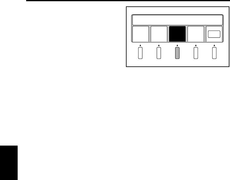
Operations in Utility mode
5-53
Operation Chapter 5
Select [Buzzer] to set when the
buzzer goes off.
Selecting [Alarm] makes the buzzer
go off only when any warning
message appears.
Selecting [Stop] makes the buzzer go
off when any prohibited operation is
attempted, as well as when any
warning message appears.
Selecting [Key in] makes the buzzer
goes off when any key is pressed and
accepted in addition to the above two
cases.
Select [No] to deactivate the buzzer.
Select [OK] to define the setting.
Alar
m
No
Enable Buzzer Settings
OK
Stop Key
in
3-2
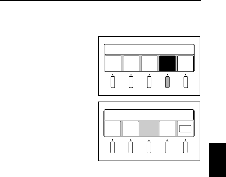
Operations in Utility mode
5-54
Operation Chapter 5
SCSI port settings
The ID number for SCSI port recognition is set. All settings defined here are effective not
only for the current operation but also when the Scanner is turned on next.
Select [SCSI set] on the main Utility
screen. The SCSI setting screen
appears.
Select [Up] or [Down] to change the
ID number from 0 to 7.
Select [Previous] to return to the
main Utility screen.
Select [OK] to define the setting.
Init
ial
Time
set
Caut
ion
SCSI
set
Main
Menu
Select Function
1
Down Up Prev
ious
Set SCSI ID ID=2
OK
2
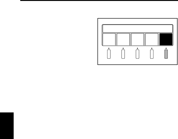
Operations in Utility mode
5-55
Operation Chapter 5
Exiting Utility mode
Select [Main Menu] on the main Utility
screen.
Init
ial
Time
set
Caut
ion
SCSI
set
Main
Menu
Select Function

Troubleshooting Chapter 6
Chapter 6
Troubleshooting

6-1
Troubleshooting Chapter 6
Potential problems
Two types of messages appear on the display according to the nature of the problem.
Warning message
When any error occurs in parameters for auto focus, auto exposure, or paper size detection
prior to scanning, a warning message appears on the display and the Scanner stops. Warning
messages can be reset by pressing any key on the control panel. Refer to the following
pages for the action required for each message.
Error message
When any error occurs in the Scanner, an
error message appears on the display, the
start key turns red, and scanning stops. In
this case, turn the power switch off and
then back on. If the same message appears
again, check the error code (numbers
following the letter “C”) and call your
authorized dealer.
C15XX
Service Call
Call Tech. Rep

6-2
Troubleshooting Chapter 6
Troubleshooting warning messages
Warning message Possible cause Action
Bind Size is Too High
Press Down Book Table
• The height of the surface of
the original is more than 65
mm above the book table.
• Lower the original so that its
surface is within the range 65
mm above the book table.
• Select Sheet mode.
• The steel mirror is dirty. • Clean the steel mirror.
• Light from the room lighting
or the outside through
windows reflects on the steel
mirror.
• Relocate the Scanner to a
place where light from the
room lighting or the outside
through windows does not
reflect on the steel mirror.
• Change settings appropriately for the original, referring to
“Notes on originals”.
Bind Size is Not Detected
Reset Book or Change Sheet
• A tag or bookmark is attached
to the original.
• Take off tags and bookmarks.
• Set the original upside down.
• Indices are provided on the
top of the original.
• Set the original upside down.
• Set the distance between the
stopper and the original in
Book mode.
• Select Sheet mode.
• The steel mirror is dirty. • Clean the steel mirror.
• The hardcover has patterns.
• Light reflects on the
hardcover.
• When the mode is Book
mode, set the distance
between the stopper and the
original.
• Change settings appropriately for the original, referring to
“Notes on originals”.
Book Exp. level is Too High
Set AE to off
• The density of the original
surface is too high.
• Cancel the setting for auto
exposure.
• Turn off Frame Masking.
• Select Sheet mode.
• The original is not correctly
set.
• No original is set.
• Change settings appropriately
for the original, referring to
“Notes on originals”.
• Set the original correctly.
Book Size is Not Detected
Reset Book or Change Sheet
• A tag or bookmark is attached
to the original.
• Take off tags and bookmarks.
• Indices are provided on the
top of the original.
• Select the Sheet mode and
cancel the Auto function.
• Set the original upside down.

Troubleshooting warning messages
6-3
Troubleshooting Chapter 6
Book Size is Not Detected
Reset Book or Change Sheet
• The original is not set
correctly.
• No original is set.
• Change settings appropriately
for the original, referring to
“Notes on originals”.
• Set the original correctly.
Right (Left) Size is Not
Detected
Reset Book or Change Sheet
• [Spread] is selected, but no
original is placed on the right
or left half of the book table.
• Select [Single] when scanning
only one page.
• Set the original correctly
when scanning a two page
spread.
• Select the Sheet mode and
cancel the Auto function.
• Change settings appropriately for the original, referring to
“Notes on originals”.
Exp. level is Not Detected
Clean Top of Steel Mirror
• The shading plate is dirty. • Clean the shading plate.
• Your hands or arms were
placed over the original
during scanning.
• Never move your hands and
arms after the start switch is
pressed.
• An obstacle is blocking the
lamp.
• Remove the obstacle blocking
the lamp.
Printer is OFF
Turn Printer ON
• Current [Output] setting is
[Printer] connection.
• Change the [Output] setting to
[PC].
Communication Error
Turn Off and On System
• Communication Error • Check connection of SCSI
cable and SCSI apparatus.
• Turn the power switch OFF
and then ON again to reset the
system.
Warning message Possible cause Action

Maintenance Chapter 7
Chapter 7
Maintenance
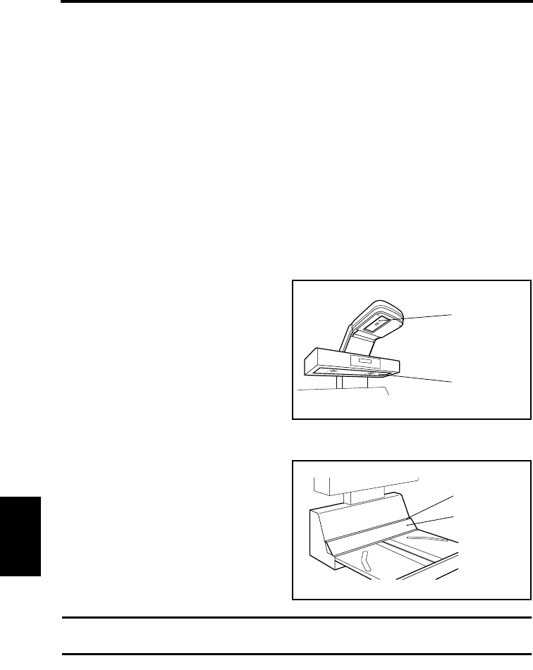
7-1
Maintenance Chapter 7
Maintenance
The following daily checks and cleaning are required to ensure the best possible
performance and utmost safety from the Scanner.
Daily checks
1. Any of the following conditions could damage the Scanner or other electrical equip-
ment. Move the Scanner immediately and eliminate the possible cause of malfunction.
• The Scanner is placed on the power cord or other cables.
• The Scanner is placed on any cord of other electrical devices.
2. If any of the following conditions is found, turn the Scanner off immediately, unplug
the power cord from the outlet, and call your authorized dealer.
• The power cord or interface cable is damaged.
• The insulation of the power cord is damaged and the bare wires are exposed.
Cleaning
Scanner glass and illumination glass
The Scanner may not scan the original
correctly if the scanner glass or
illumination glass is dirty. Wipe the
surfaces with a dry soft cloth to remove
dirt.
Steel mirror and shading plate
The height of the original is not correctly
measured if the steel mirror or shading
plate is dirty, resulting in a warning
message. Wipe the surfaces with a dry soft
cloth to remove dirt.
NOTE
Be sure to turn the Scanner off and unplug the power cord before cleaning.
Scanner glass
Illumination glass
Steel mirror
Shading plate

Specifications Chapter 8
Chapter 8
Specifications

8-1
Specifications Chapter 8
Product specifications
Type: Desk-top book scanner for face-up originals
Scanning system: Rotary mirror scanning system
Original type: Book, Sheet
Original size: Max. 432 mm x 594 mm (Scanning area)
Original thickness: 100 mm: Less than A3 or 17”
(effective range: within 300 mm in longitudinal direction)
50 mm: Less than A2 or 23”
(effective range: within 420 mm in longitudinal direction)
Resolution: 200/240/300/400/600 dpi
Image sensor: Reducing-type line CCD (7500 pixels)
Light source: Long cylindrical halogen lamp (DC150V, 620 W)
Exposure Adjustment: Automatic (9 steps) or Manual (9 steps)
Focus: Automatic or Manual (0-50 mm or 0-2”)
Shadow ensure: Automatic function erases the shadow generated
between pages
Image correction: Curved text line correction by zoom adjustment in
scanning direction
Text compression correction by space adjustment in sub-
scanning direction
Text/Photo mode: Outline accentuation and smoothing method
Finger mask: Fingers holding the original erased
spread mode single mode
Landscape A2, B3, A3, B4,
A4, B5, A5
or
17” x 23”,
14” x 22”,
14” x 17”,
11” x 17”,
11” x 14”,
8-1/2” x 14”,
8-1/2” x 11”,
5-1/2” x 8-1/2”
A4, B5, A5,
or
8-1/2” x 11”,
5-1/2” x 8-1/2”
Portrait A3, B4, A4, B5, A5
or
14” x 17”,
11” x 17”,
11” x 14”,
8-1/2” x 14”,
8-1/2” x 11”,
5-1/2” x 8-1/2”
A3, B4, A4, B5,
A5, B6, A6
or
11” x 17”,
11” x 14”,
8-1/2” x 14”,
8-1/2” x 11”,
5-1/2” x 8-1/2”

Specifications
8-2
Specifications Chapter 8
Frame masking: Object (frame) outside the original erased
Centering: Scanned image printed out in the center of the paper
Scan mode: Spread / Single / Book Split
Scanning speed: 4.5 sec/page (A4, right page only, 400 dpi, AE, auto
frame masking, finger masking, center masking)
Dimensions: 730 mm (W) x 745 mm (D) x 975 mm (H) or
28-3/4”(W) x 29-5/8”(D) x 38-3/8” (H)
Weight: 64 kg (140 lbs)
Power source: 120 V, 60Hz/ 220-240V, 50-60Hz
Max. power consumption: Less than 1000 W
Operation noise: Standby-state:30 dB or less, Operation:62 dB or less
Interface: Video I/F (Printer), SCSI-2 (PC)
Option: Angle Book Holder, System Printer & PR Interface Kit,
Foot Switch, Gray Scale Memory Board

8-3
Specifications Chapter 8
For Key Operator’s Use
When you need to call for service, the Key Operator should be prepared to provide the
following information to your local authorized Dealer.
1. Your Company Name, Address, Telephone Number, Department Name, Floor Number,
Machine Location, etc.
2. Model Name, Serial Number, Condition or System(s) Indication(s) on the Display. etc.
For your reference purpose.
Model Name PS7000
Installation Data
Authorized Dealer’s Name
TEL. No.
Address
Serial No.

Copyright
1999 MINOLTA CO., LTD
Printed in Japan
The information contained in this manual is
subject to change without notice to
incorporate improvements made on the
product or products the manual covers.
MINOLTA CO., LTD.
Image Information Products Marketing Headquarters
3-13, 2-chome, Azuchi-machi, Chuo-ku, Osaka. 541-8556, Japan
2000. 8
