Minorplanet Systems PLC AEM3000DCU AVL and Data Logging System User Manual 1
Minorplanet Systems PLC AVL and Data Logging System 1
manual

MINORPLANET
AEM3000 DCU
AVL & Data Logging System
System overview & Installation Guide
AEM3000 DCU
WM1002 B Issue 1 page 1 of 13

MINORPLANET
Contents Page
1. Operation
System Configuration ...................................................................….3
System Overview ..............................................................................3
System Operation .............................................................................4
Component Layout ........................................................................... 4
2. Safety Precautions
General Safety ..................................................................................5
Electrical Safety ................................................................................ 5
Safety Standards ............................................................................... 5
3. General Installation
Mechanical Assembly ....................................................................... 6
DCU Installation ................................................................................ 7
Electrical Wiring ................................................................................ 8
GPS Antenna Fitting ......................................................................... 9
GSM Antenna Fitting ........................................................................ 10
4. Commissioning
Test Procedures ............................................................................... 10
Trouble Shooting ............................................................................…11
5. Technical Specifications
Mechanical Specification ...............................................................….12
Electrical Specification ...................................................................….12
GPS Antenna Specification ............................................................….12
GSM Antenna Specification .............................................................…12
AEM3000 DCU
WM1002 B Issue 1 page 2 of 13
MINORPLANET
1. OPERATION
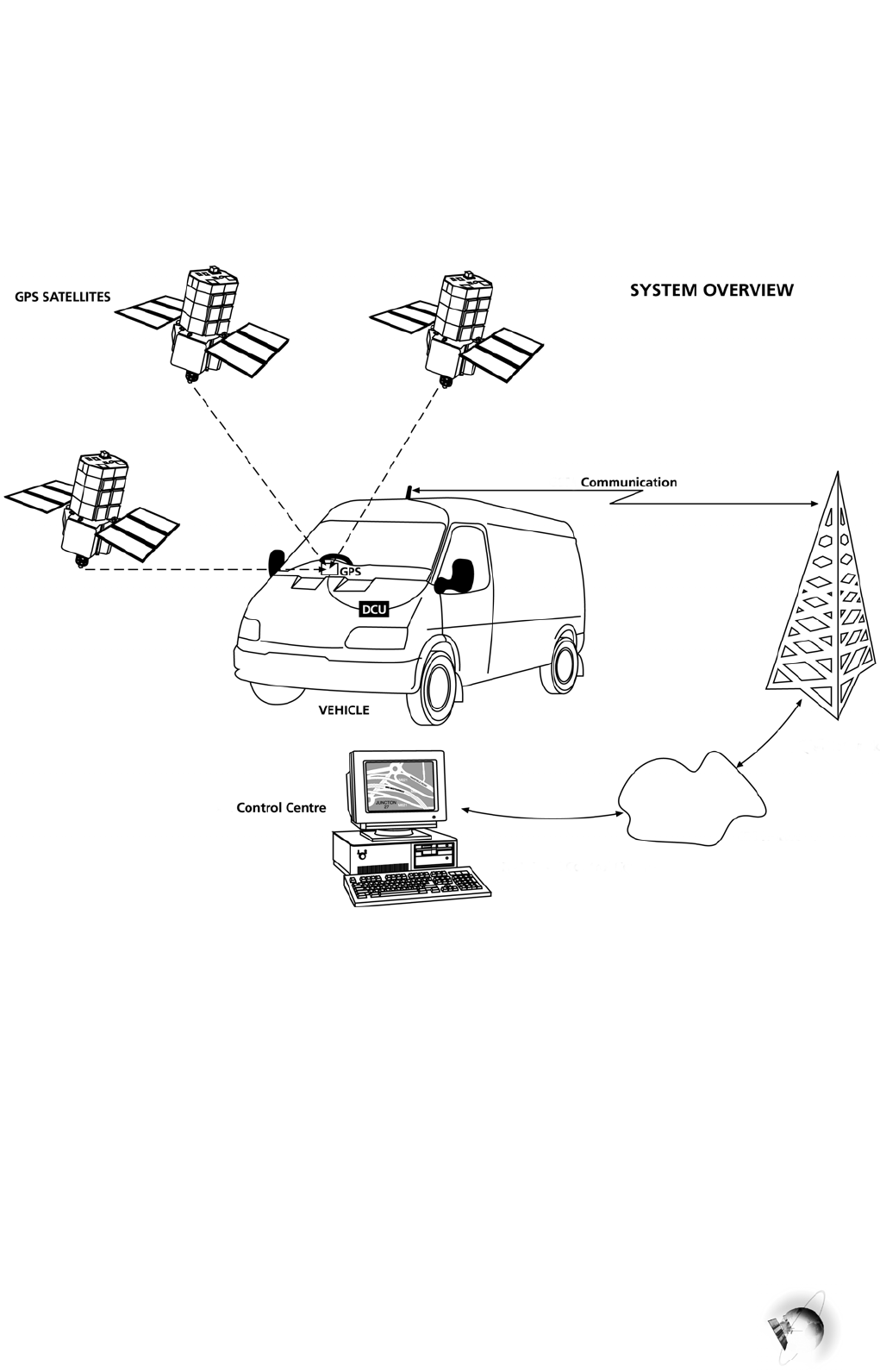
1.1 Maptrack System Overview
The Maptrack system brings together satellite based global positioning technology, microprocessor
control, low power radio and international GSM communication infrastructure to achieve wide area
communication, vehicle location, telematics and communication services.
1.1.1 OPERATION OVERVIEW
1.2 System Overview
The AEM3000 is an electronic data collection and transmission device, incorporating GPS tracking and
GSM communication technologies.
Whilst the vehicle is in use, geographical and operational data is continually monitored and recorded within
the DCU (data collection unit) memory. Up to 8 weeks of operational data can be held within the DCU. If
the memory capacity is reached before the data is downloaded, the oldest records will be lost as new
records are recorded.
Recorded data may be downloaded for processing by the base computer in the following ways;
a) bulk download of all held data via the GSM data channel
b) snap shot of current ‘live’ data via the GSM SMS network.
c) bulk download of held data via the low power radio interface upon return to base.
Interrogation of the DCU is possible anywhere that benefits from GSM network coverage (subject to
roaming agreements with GSM networks).
AEM3000 DCU
WM1002 B Issue 1 page 3 of 13
MINORPLANET
1.3 System Operation
The Maptrack in-vehicle system consists of the DCU (data collection unit), GPS and GSM antennae.
Only power and ignition connections are made to the vehicle electrical system.
When an ignition signal is present at the DCU the system records a start event and activates the GPS
receiver, the vehicles geographical position, velocity and distance travelled are then continually recorded
within the DCU until the ignition signal is removed, at which time a stop event is recorded, the DCU then
performs any outstanding tasks before powering down the GPS receiver and GSM transceiver.
The DCU will stay in this power save mode until either the ignition is turned on or a command is received
form the monitoring bureau to reactivate.
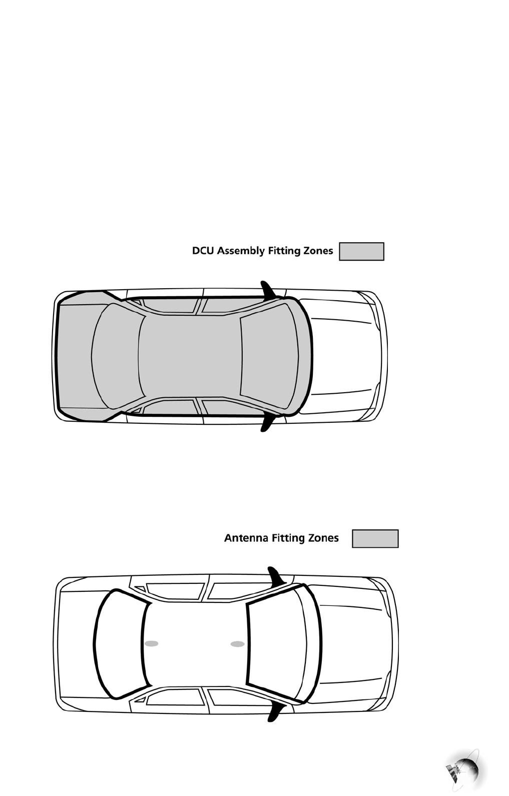
1.4 Component Layout
The following equipment positioning guides are for reference only and are not intended to be exhaustive.
Actual optimum positions will change depending upon type of vehicle being fitted.
1.4.1 DCU POSITION GUIDE (within vehicle)
1.4.2 TRI-BAND AERIAL POSITION GUIDE (roof of vehicle)
AEM3000 DCU
WM1002 B Issue 1 page 4 of 13

MINORPLANET
SAFETY PRECAUTIONS
2.1 General Safety
It is the installation engineers’ responsibility to asses all potential risks before commencing work on the
host vehicle and be fully conversant with all vehicle operating procedures and workshop practices.
The following points are for guidance only and are not intended to be exhaustive:
2.1.1 never work under a vehicle, which is supported solely by jacks.
2.1.2 the vehicle should always be left out of gear.
2.1.3 never perform any tasks, which would jeopardise your own or the operational safety of the vehicle.
2.1.4 always remove and replace vehicle trim with correct tools and in line with manufacturers instructions.
2.1.5 take extreme caution not to damage or disrupt air bag or supplementary restraint systems (SRS).
2.1.6 if additional mountings are required, these should be drilled within the vehicle manufacturers guidelines.
2.1.7 never operate the system with damaged unapproved parts.
2.2 Electrical Safety
It is the installation engineer’s responsibility to asses all potential risks before commencing work on the
host vehicle and be fully conversant with all auto electrical procedures and workshop practices.
The following points are for guidance only and are not intended to be all-inclusive:
2.2.1 it is advisable to disconnect the vehicle battery prior to making any electrical connections.
2.2.2 never attempt to test any electrical circuits using a test lamp.
2.2.3 remove or cover any jewellery if it is necessary to work on live electrical systems.
2.2.4 never tamper with or disconnect the air bag or SRS electrical harness.
2.2.5 refer to the vehicle manufacturer’s instructions when making supplementary electrical connections.
2.2.6 use a high impedance multi-meter with both voltage and resistance ranges for testing electrical circuits.
2.2.7 always fuse supplementary power connections at source to protect against electrical fire if damaged.
2.2.8 take extreme care not to trap or damage any cables when replacing the vehicle trim.
2.2.9 check that vehicle electronic equipment is adequately shielded from RF energy before fitting the DCU or
GSM antenna in the direct vicinity of any electronic control or management systems.
2.3 Safety Standards
The AEM3000 DCU and associated equipment has been fully EMC tested to VCA recommendations in
accordance with European Directive 95/54/EC, Annex 7 & 8 (emissions).
The cellular modem contained within the DCU complies with all applicable RF safety standards and
recommendations for the protection of public exposure to RF electromagnetic energy as defined by
directives of the European Community.
As the AEM3000 DCU contains a cellular radio modem it should not be fitted or used within any
potentially explosive atmospheres, within any vehicle powered by liquefied petroleum gas or governed by
petrochemical regulations without additional operational safety precautions being taken.
3. GENERAL INSTALLATION
AEM3000 DCU
WM1002 B Issue 1 page 5 of 13
MINORPLANET
The manufacturer cannot accept responsibility for any operational failure of vehicle systems or
consequential loss resulting from failure to comply with recognised workshop practices, installation
guidelines or vehicle manufacturers recommendations.
3.1 Mechanical Assembly
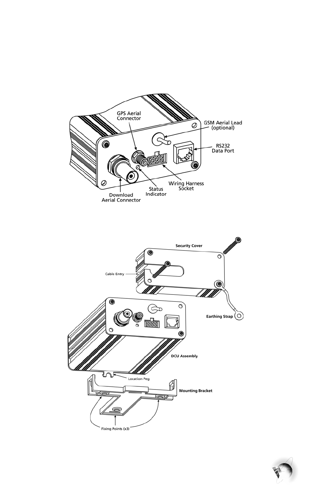
The following diagrams show the general mechanical configuration of the DCU, refer to the relevant
detailed instructions for the recommended fitting and assembly procedures.
3.1.1 DCU BULKHEAD LAYOUT
4.1.14 DCU GENERAL ASSEMBLY
3.2 DCU Installation
The heart of the Maptrack system is the DCU (data collection unit). It is essential that this and all other
system components are securely fixed and very well concealed.
AEM3000 DCU
WM1002 B Issue 1 page 6 of 13

MINORPLANET
The actual position of the DCU and indeed the antennae should be varied to reduce the opportunity of
discovery. Ideally the termination end of the DCU should be directly adjacent to an existing vehicle wiring
loom, providing easier concealment of system wiring.
Please note that the AEM3000 DCU is not waterproof and should only be fitted within an
environmentally protected area of the vehicle.
The following recommended procedure should be followed;
3.2.1 conduct pre installation tests.
3.2.2 select installation position, be sure to leave sufficient room for the tamper protection cover.
3.2.3 secure fixing bracket using three No 8 x ¾ inch self-tapping screws (provided in fixing kit).
3.2.4 ensure that vehicle electrical supply is isolated and made safe.
3.2.5 make electrical connections and fit antennae as detailed in sections 3.1 & 3.4.
3.2.6 route cables to DCU fixing position and conceal by looming in with existing vehicle wiring.
3.2.7 screw the GPS aerial plug onto the SMA bulkhead socket at the DCU (see section 3.1.1)
3.2.8 screw the GSM aerial plug onto the FME free cable socket at the DCU (see section 3.1.1)
3.2.9 screw the LPR aerial plug onto the BNC bulkhead socket at the DCU (see section 3.1.1)
3.2.10 plug the power harness into the DCU, ensuring that the retaining clip is fully located.
3.2.11 reconnect vehicle electrical supply.
3.2.12 perform all system tests as described in section 4.1.
3.2.13 secure auxiliary fuse covers in place using cable ties provided.
3.2.14 pass the protection cover over cables and secure in place using the security screws provided.
3.2.15 tidy and protect remaining cables.
3.2.16 replace vehicle trim etc. and ensure that all accessories / settings are returned to their original state.
3.2.17 conduct post installation test.
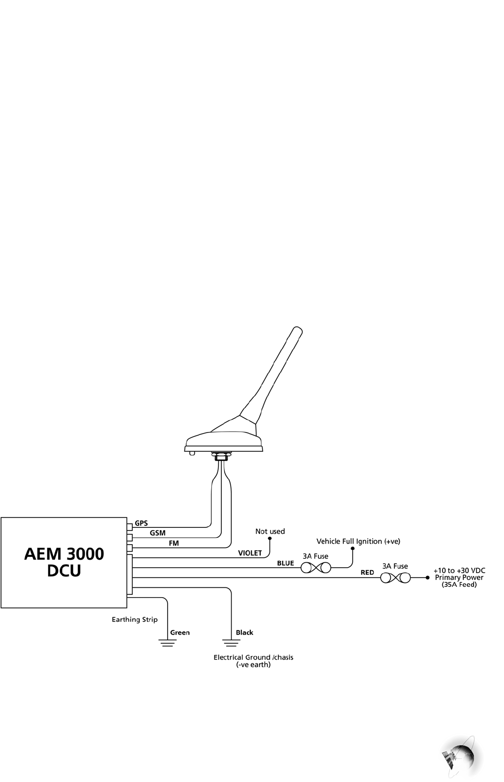
3.3 Electrical Wiring
All connection must be wrapped and soldered. Crimped connections are not suitable.
3.3.1 NEGATIVE POWER SUPPLY (GND) - Black Wire
AEM3000 DCU
WM1002 B Issue 1 page 7 of 13
MINORPLANET
Always connect directly to a dedicated earth point within the vehicle electrical system.
Never connect to any other electrical earth or drill and strap any part of the vehicle body, as build
up in contact resistance may cause supply voltage problems, resulting in erratic operation of the
DCU.
3.3.2 POSITIVE POWER SUPPLY (+VE) - Red Wire
Connect to a continuous +12 to +24 volt DC supply. This should be taken from the secondary side of the
main distribution fuse from the vehicle battery, and should not share a fused supply to any other
equipment. This line should be fused at source to provide protection against shorting of the wiring harness,
(DCU is internally fused).
To avoid mis-operation ensure that the power is not interrupted when the engine is being started.
3.3.3 IGNITION SENSE INPUT - Blue Wire
Connect to an ignition signal which goes positive (+10 to +30 volt DC) when the engine is running, and
is removed or goes to ground when the engine stops.
The auxiliary ignition feed is not suitable as this may result in the false operation of the DCU
3.3.4 SECONDARY EARTHING - Black Wire
To comply with EMC requirements, the earth strap provided must be terminated to an electrically
tested chassis ground in the direct vicinity of the DCU.
3.3.5 ELECTRICAL WIRING DIAGRAM
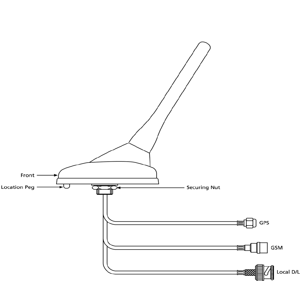
3.4 Antenna Fitting
3.4.1 GENERAL CONSIDERATIONS
AEM3000 DCU
WM1002 B Issue 1 page 8 of 13
MINORPLANET
Radio signals can be affected by metal structures or electrical systems; therefore it is essential that the
antennae element(s) is located away from sources of electrical or mechanical interference. Take care not
to route either antenna cable near any sensitive electrical systems or controls.
3.4.2 GPS
ANTENNA
It is essential that when the antenna be fitted the following considerations are observed;
a) view of the sky must be as wide as possible
b) field of view must not be obscured by any metallic substance
c) top of antenna must point towards field of view
d) navigation must be tested rigorously to ensure optimum performance under operational conditions.
3.4.5 GSM ANTENNA ELEMENT
The GSM antenna should be fitted observing the following guidelines;
a) fit the GSM antenna as far away from vehicle management and control systems as possible.
b) the GSM antenna should be fitted in such a way that it is not shielded by metallic surfaces.
c once fitted, cut the antenna lead to length and terminate using the FME plug provided.
3.4.6 LOW POWER RADIO ANTENNA ELEMENT
The low power radio contained within the AEM3000 DCU is designed to comply with FCC directive part
15, as such only aerials approved and supplied by Minorplanet may be used in conjunction with this
product. It is forbidden to use any antennae other than those verified and approved by Minorplanet.
4. COMMISSIONING
Once all cables are terminated and aerial leads connected, the system should be tested for
correct functional operation, visual indication of operating status is provided, (see 3.1.1).
AEM3000 DCU
WM1002 B Issue 1 page 9 of 13

MINORPLANET
4.1 Test Procedure
The following operational tests should be conducted outdoors with an unobstructed view of the
sky and in an area of known GSM coverage.
4.1.1 ensure that antenna is securely fitted and cables connected to the DCU.
4.1.2 fit the harness protection fuses into their holders and close fuse holder caps (do not secure).
4.1.3 turn the vehicle ignition to the full on position (ignition input signal +VE).
4.1.4 plug power harness into DCU, the status indicator should immediately flash Green and Red.
4.1.5 wait 30 seconds for the DCU to initialise and run its internal diagnostic test.
4.1.6 the status indicator should now show Amber. This indicates ignition on, but no GPS navigation.
4.1.7 wait for the status indicator to turn Green (upto 3 min. max). This indicates correct GPS navigation.
4.1.8 after approx. 1 min. the status indicator will start to flash every 10 sec. This confirms GSM operation.
4.1.9 turn the vehicle ignition off; the status indicator will turn Red to indicate that the DCU is shutting down.
4.1.14 after 20 sec. the status indicator will flash to indicate that the DCU is in download mode.
4.1.15 the DCU will now attempt to initiate a LPR download for a period of 2 minutes, after which time the DCU
will fully shut down. During the LPR download period a radio download test may be conducted.
4.1.11 turn the vehicle ignition on again, the status indicator will turn Amber and then Green when navigating.
4.1.12 call technical help desk to confirm installation and request remote test.
4.1.13 when the DCU receives a GSM message, the status indicator will flash rapidly (if ignition on).
4.1.14 upon completion of the remote test the technical help desk will confirm correct operational status.
4.2 Trouble Shooting
AEM3000 DCU
WM1002 B Issue 1 page 10 of 13

MINORPLANET
ALL DCU assemblies are 100% factory tested prior to despatch, in the unlikely event of the system does
not appear to function correctly, please refer to the following guide to help diagnose any potential errors
made upon installation:
4.2.1 FAULT FINDING GUIDE
FAULT REASON ACTION
Status indicator fails to
illuminate.
No power connected to DCU. Check fuses and supply wiring
Status indicator flashes when
power is connected but then
stays off.
Ignition signal is not present at
DCU
Check ignition line fuse and
wiring to vehicle ignition line
DCU ‘live’ test only works when
vehicle ignition is on.
DCU power & ignition wiring is
reversed.
Check power / ignition wiring
and correct fault.
Status indicator stays Amber
after 5 min. from power up.
(ignition on)
GPS navigation is not achievable
under current conditions.
Ensure that GPS aerial has a
wide view, without metallic
obstruction.
No GPS navigation (no metallic
obstructions, wide field of view)
Antenna orientation or position
is not allowing full satellite
comm.
Reorientate aerial within 30 deg.
of horizontal for best
performance.
Status indicator does not flash
(amber or green light only).
GSM communication is not able
to initialised correctly.
Check for good signal strength
and reposition GSM aerial.
No GSM initialisation after 10
min. (signal strength aerial OK)
Network registration failed or
SIM card not active.
Check GSM aerial installation
and reposition if necessary.
DCU appears to work correctly
but will not shut down with
ignition off.
Ignition sense wiring connected
to permanent +ve voltage.
Check wiring and if necessary
correct fault.
DCU reinitialises (indicator
flashes red/green) when engine is
started.
Power is being temporarily
removed upon starting of the
vehicle.
Rewire DCU power to a
permanent uninterruptible power
source.
System operates correctly until
after the vehicle immobiliser is
operated.
Some immobilisers isolate
auxiliary power circuits for
safety reasons.
Rewire DCU power to a
permanent uninterruptible power
source.
System only works when vehicle
door(s) are open.
DCU power has been taken from
+ve switched interior light
circuit.
Rewire DCU power to a
permanent uninterruptible power
source.
Status indicator repeatedly
flashes spasmodically and will
not stabilise.
GSM modem has failed to
initialise correctly.
Power down system, check GSM
aerial & power level then re-
power.
If it is not possible to identify the actual cause of a fault by following the above guide, make a note of the status of
the DCU, any fault symptoms along with the make, model and year of vehicle. With this information please call the
technical help desk who will be pleased to provide additional assistance if required.
5. TECHNICAL SPECIFICATION
Due to continuous product development, aspects of the following specification may be changed without
notice and solely at the discretion of the manufacturer.
AEM3000 DCU
WM1002 B Issue 1 page 11 of 13

MINORPLANET
5.1 Mechanical Specification (DCU)
Size (mm) : 82
W x 40 H x 140 L (170 inc. tamper cover).
Weight : 480 grams.
Material : Aluminium main body, polycarbonate rear end cover.
5.2 Electrical Specification
Supply Voltage : 10.80 to 31 volts DC.
Current @ 12V : 400 mA Maximum.
: 210 mA Typical.
: 60 mA Power save (Ave).
Current @ 24V : 260 mA Maximum.
: 130 mA Typical.
: 50 mA Power save (Ave).
Ignition Sense : 8 to 31 volts DC.
Protection : 3 Amp line protection fuses (2 off) supplied.
GSM modem : ETSI full type approved, 890-960 MHz 2 Watt (max) Transceiver.
GPS receiver : 12 parallel channels, GPS rollover & Y2K compliant.
LPR Transceiver : 902.75MHz max 1 mW @ 3M, FCC xxxxx part 15 compliant
Operating Temp : -20 to +50 degrees centigrade.
EMC : Tested to meet European directive 95/54/EC (emissions)
5.3 GPS Antenna Specification
Technology : 1575.42 MHz, 5 volt active ceramic patch (ground plane dependent).
Cable : 4 metre, type 174 (50 Ohm coaxial).
Connector : SMA free cable plug
5.4 GSM Antenna Specification
Technology : 890 - 960 MHz, ground plane independent.
Cable : 4 metre, type 174 (50 Ohm coaxial).
Connector : FME free cable plug
5.5 LPR Antenna Specification
Technology : 900-928 MHz, ground plane dependant.
Cable : 4 metre, type 174 (50 Ohm coaxial).
Connector : BNC free cable plug
F.C.C.CAUTION: THIS DEVICE COMPLIES WITH PART 15 OF THE FCCRULES. OPERATION IS SUBJECT
TO THEFOLLOWING TWO CONDITIONS: (1) THIS DEVICE MAY NOT CAUSE HARMFULINTERFERENCE,
AEM3000 DCU
WM1002 B Issue 1 page 12 of 13

MINORPLANET
AND (2) THIS DEVICE MUST ACCEPT ANY INTERFERENCE RECEIVED,INCLUDING INTERFERENCE THAT
MAY CAUSE UNDERSIRED OPERATION. NOTE: NO CHANGES OR MODIFICATIONS MAY BE MADE TO
THE UNITS. ANY CHANGES MADE TO THE UNITS WILL VOID THEUSER’S AUTHORITY TO OPERATE THE
EQUIPMENT.
AEM3000 DCU
WM1002 B Issue 1 page 13 of 13