Minorplanet Systems PLC AEMB100 AVL and Data Logging System User Manual 1
Minorplanet Systems PLC AVL and Data Logging System 1
Contents
- 1. Base antenna
- 2. manual
manual

MINORPLANET
AEMB100 Base Station
AVL & Data Logging System
System Overview & Installation Guide
AEMB100 Base Station
WM1003 Issue 1

MINORPLANET
1. OPERATION
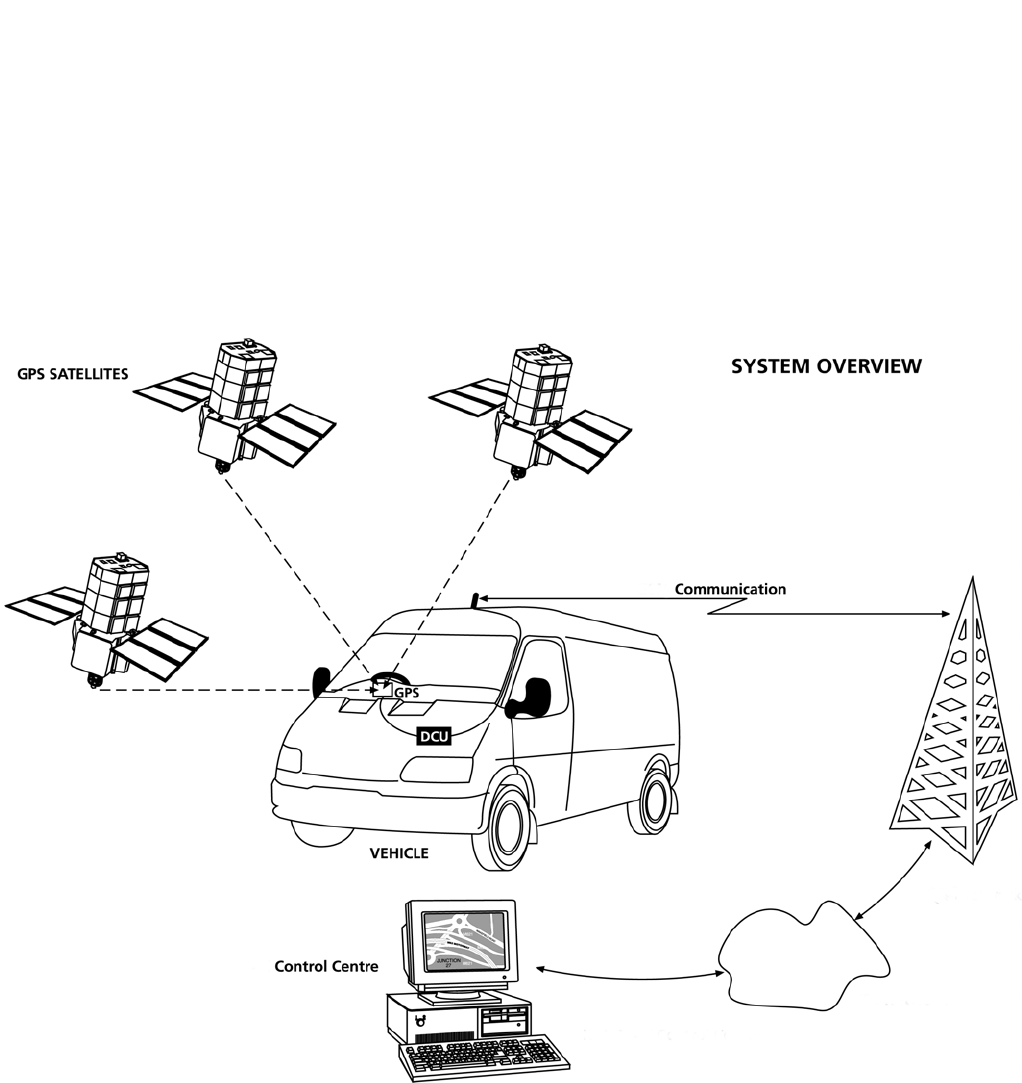
1.1 Maptrack System Overview
The Maptrack system brings together satellite based global positioning technology, microprocessor control,
low power radio and international GSM communication infrastructure to achieve wide area communication, vehicle
location, telematics and communication services.
1.1.1 Operation Overview
1.2 System Overview
The AEM3000 is an electronic data collection and transmission device, incorporating GPS tracking and
GSM communication technologies.
Whilst the vehicle is in use, geographical and operational data is continually monitored and recorded within the
DCU (data collection unit) memory. Up to 8 weeks of operational data can be held within the DCU. If the memory
capacity is reached before the data is downloaded, the oldest records will be lost as new records are recorded.
Recorded data may be downloaded for processing by the base computer in the following ways;
a) bulk download of all held data via the GSM data channel
b) snap shot of current ‘live’ data via the GSM SMS network.
c) bulk download of held data via the FCC compliant low power radio interface upon return to base.
Interrogation of the DCU is possible anywhere that benefits from GSM network coverage (subject to
roaming agreements with GSM networks).
AEMB100 Base Station
WM1003 Issue 1

MINORPLANET
1.3 System Operation
The Maptrack in-vehicle system consists of the DCU (data collection unit), GPS, GSM and Low Power Local
Download antennae. Only power and ignition connections are made to the vehicle electrical system.
When an ignition signal is present at the DCU the system records a start event and activates the GPS receiver, the
vehicles geographical position, velocity and distance travelled are then continually recorded within the DCU until
the ignition signal is removed, at which time a stop event is recorded, the DCU then performs any outstanding
tasks before powering down the GPS receiver and GSM transceiver.
When the vehicles ignition is turned off, the low power radio will power up and transmit a ‘Come And Get Me’
(CAGM) packet. If the vehicle is within range of its AEMB100 Base Station this packet will be received by the Base
Station, which will request a transfer of data from the Vehicle to the Base Station. This transfer of data is via the
Low Power Radio link in a half-duplex packet format.
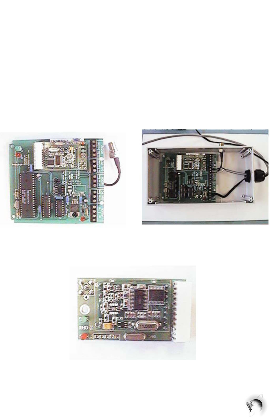
1.4 AEMB100 Component Layout
AEMB100 PCB Assembly AEMB100 Internal Wiring
Radio Packet Controller Detail
AEMB100 Base Station
WM1003 Issue 1

MINORPLANET
2. SAFETY STANDARDS
The AEMB1000 Base Station and associated equipment has been fully EMC tested to VCA recommendations in
accordance with European Directive 95/54/EC, Annex 7 & 8 (emissions).
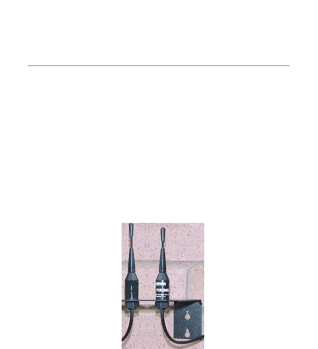
2.1 Low Power Radio Antenna Element
The low power radio contained within the AEMB100 Base Station is designed to comply with FCC directive part
15. As such only aerials approved and supplied by Minorplanet may be used in conjunction with this product. It is
forbidden to use any antennae other than those verified and approved by Minorplanet.
Both the AEMB100 Base Station and its associated antenna must be installed, and/or protected, in such a way that
they will be inaccessible to normal pedestrian traffic after installation.
3. TECHNICAL SPECIFICATION
Due to continuous product development, aspects of the following specification may be changed without
notice and solely at the discretion of the manufacturer.
3.1 Mechanical Specification AEMB100 Base Station
Size (mm) : 112
W x 70 H x 200 L.
Weight : 400 grams.
Material : Two part impact resistant polystyrene.
3.2 Electrical Specification
Supply Voltage : 9 to 12 volts DC.
Current @ 12V : 120 mA Maximum.
LPR Transceiver : 902.75MHz max 1 mW @ 3M, FCC part 15 compliant
Operating Temp : -20 to +50 degrees centigrade.
EMC : Tested to meet European directive 95/54/EC (emissions).
AEMB100 Base Station
WM1003 Issue 1

MINORPLANET
3.3 LPR Antenna Specification
SPECIFICATIONS
Frequency Range 902 – 925 MHz
PCS: 1850 - 1980 MHz
VSWR <2:1
Vertical 3 dB beamwidth 72° typ
Rated Power 10 Watts
Impedance 50 ohms
Termination N-type female on 1 m Low Loss RG58 cable tail
Material Radiator: 7/7 PH stainless steel
Cover:: ABS
Operating Temperature -20°C to +80°C
Mounting With bracket onto wall
Antenna Size 150mm high on 55x200mm bracket
Packing Weight / Volume 0.2kg / 25 x 20 x 6cm
It should be noted that the above information indicates the typical antenna to be used for local download purposes.
AEMB100 Base Station
WM1003 Issue 1

MINORPLANET
AEMB100 Base Station
WM1003 Issue 1
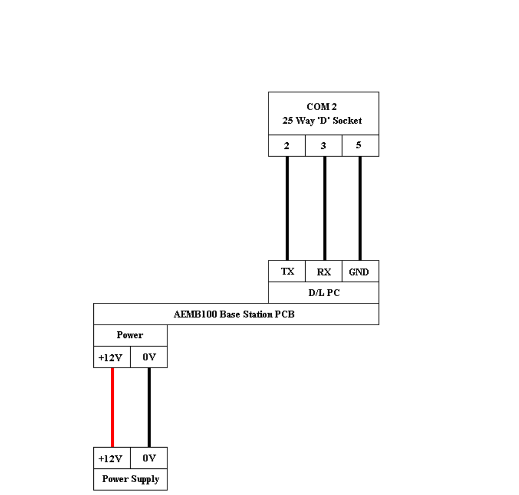
4.1 AEMB100 WIRING DIAGRAM
F.C.C.CAUTION: THIS DEVICE COMPLIES WITH PART 15 OF THE FCC RULES. OPERATION IS SUBJECT TO
THE FOLLOWING TWO CONDITIONS: (1) THIS DEVICE MAY NOT CAUSE HARMFUL INTERFERENCE, AND
(2) THIS DEVICE MUST ACCEPT ANY INTERFERENCE RECEIVED, INCLUDING INTERFERENCE THAT MAY
CAUSE UNDERSIRED OPERATION. NOTE: NO CHANGES OR MODIFICATIONS MAY BE MADE TO THE
UNITS. ANY CHANGES MADE TO THE UNITS WILL VOID THE USER’S AUTHORITY TO OPERATE THE
EQUIPMENT.