Mipro Electronics Co 3031325052T Bodypack Transmitter User Manual ACT 30T 2CE347A 20110715
Mipro Electronics Co Ltd Bodypack Transmitter ACT 30T 2CE347A 20110715
Users Manual
MIPRO Electronics Co., Ltd.
Headquarters: 814 Pei-Kang Road, Chiayi, 60096, Taiwan.
Web: www.mipro.com.tw
E-mail: mipro@mipro.com.tw
AS110715
Design and specifications are subject to change without prior notice
ACT-30T Bodypack Transmitter
User Guide
2 CE3 4 7 A
1. Read these instructions.
2. Keep these instructions.
3. Heed all warnings.
4. Follow all instructions.
5. Do not use this apparatus near water.
6. Clean only with a dry cloth.
7. Do not block any ventilation openings. Install in accordance
with the manufacturer's instructions.
8. Do not install near any heat sources such as radiators, heat
registers, stoves, or other apparatus (including amplifiers)
that produce heat.
9. Do not defeat the safety purpose of the polarised or ground
plug: A polarised plug has two blades with one wider than
the other. The wide blade is provided for your safety. When
the provided plug does not fit into your outlet, consult an
electrician for replacement of the obsolete outlet.
10. Protect the power cord from being walked on or pinched
particularly at plug, convenience receptacles, and the point
where they exit from the apparatus.
11. Only use attachments/accessories specified by the
manufacturer.
12. Use only with a cart, stand, tripod, bracket, or
table specified by the manufacturer, or sold
with the apparatus. When a cart is used, use
caution when moving the cart/apparatus
combination to avoid injury from tip-over.
13. Unplug this apparatus during lightning storms or when
unused for long periods of time.
14. Refer all servicing to qualified service personnel. Servicing is
required when the apparatus has been damaged in any way,
such as power-supply cord or plug is damaged, liquid has
been spilled or objects have fallen into the apparatus, the
apparatus has been exposed to rain or moisture, does not
operate normally, or has been dropped.
15. To reduce the risk of fire or electric shock, do not expose
this apparatus to rain or moisture.
16. Apparatus should not be exposed to dripping or splashing
and no objects filled with liquids, should be placed on the
apparatus.
17. Use only with the battery which specified by manufacturer.
18. The power supply cord set is to be the main disconnected
device.
! IMPORTANT SAFETY INSTRUCTIONS ! WARNING
This symbol indicates that dangerous voltage constituting a
risk of electric shock is present within this unit.
This symbol indicates that there are important operating and
maintenance instructions in the literature accompanying this
unit.
1. FOR OUTDOOR USE:
To reduce the risk of fire or electric shock, do not expose this
apparatus to rain or moisture.
2. UNDER WET LOCATION:
Apparatus should not be exposed to dripping or splashing and no
objects filled with liquids, such as vases should be placed on the
apparatus.
3. SERVICE INSTRUCTIONS:
CAUTION - These servicing instructions are for use by qualified service
personnel only. To reduce the risk of electric shock, do not perform any
servicing other than that contained in the operating instructions unless
you are qualified to do so.
Dispose of any unusable devices or batteries responsibly and
in accordance with any applicable regulations.
Disposing of used batteries with domestic waste is to be
avoided!
Batteries / NiCad cells often contain heavy metals such as
cadmium(Cd), mercury(Hg) and lead(Pb) that makes them
unsuitable for disposal with domestic waste. You may return
spent batteries/ accumulators free of charge to recycling
centres or anywhere else batteries/accumulators are sold.
By doing so, you contribute to the conservation of our
environment!
Disposal
2005- 08-132005- 08-13
THIS DEVICE COMPLIES WITH PART 74 OF THE FCC RULES AND
RSS-123 ISSUE2 OF CANADA. OPERATION IS SUBJECT TO THE
FOLLOWING TWO CONDITIONS:
(1) This device may not cause interference.
(2) This device must accept any interference, including interference
that may cause undesired operation of the device. This equipment
complies with FCC RF radiation exposure limits set forth for an
uncontrolled environment.
& IC - ID

01
Bodypack Transmitter Bodypack Transmitter
!
!
!
!
!
Sturdy, lightweight, miniature-sized housing.
Backlit LCD displays on transmitters for easy
adjustment on dark stages.
ACT™ syncs the transmitter and receiver
frequency automatically.
Pilotone squelch for interference-free operation.
Built-in transmitter gain adjustment.
!Impedance selectable switch for microphone or
guitar.
!4-pin mini XLR connector is compatible with all
MIPRO lavalier, headworn microphones and
instrument cable.
!Silent on/off switch.
!4-segment battery status meter.
!LCD displays group, channel & error message
code.
!20-hour battery life per 2 'AA' alkaline batteries.
!ACT-30T is a 24MHz bandwidth bodypack
transmitter. Plastic housing and is compatible with
ACT-311, ACT-312, ACT-311T and ACT-312T
receivers.
1 Key Features
3 Bodypack Controls and Indicators
5 O
Display Screen
ransmitter Parameters
14 Battery Status
15 AF
attery Removal and Installation
perating Instructions
6 LCD
7 T
Input Connections
16 B
Key FeaturesContents
07 05 07 05
AF MUTE
CH GRP
22
33
44
55
88
1111
1212
1313
1010
11
66
77
99
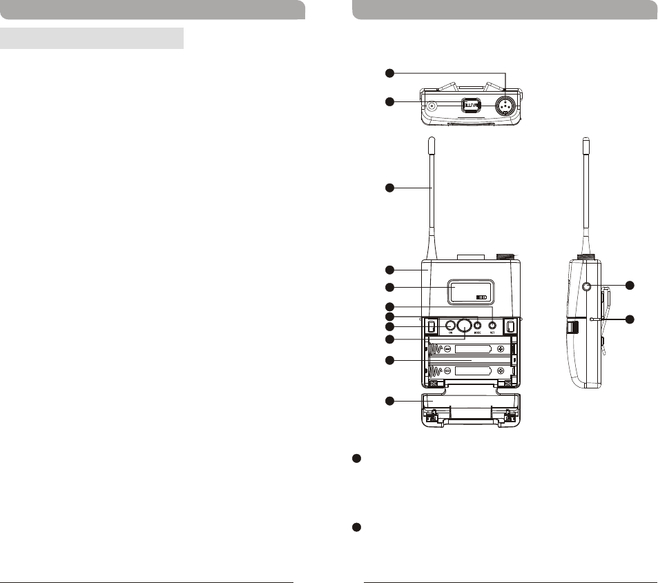
MUTE Button: To mute and un-mute the audio
signal temporary.
Audio Input Connector: TA4F mini 4-pin
connector accepts any MIPRO lavalier, instrument
and headset microphones and cables. (See 5
ways of connection on AF Input Connections)
22
11
Bodypack Controls and Indicators
!USER GUIDE ×1
Furnished Accessories:
23
Bodypack Transmitter Bodypack Transmitter
Operating Instructions
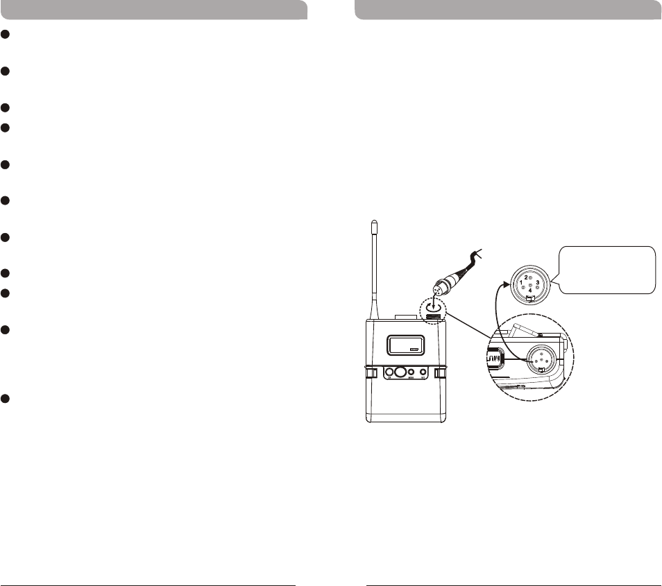
(Figure 2)
!The audio gain level is factory preset at
Microphone-Low level. Guitar setting is
recommended at LINE level.
!
!
Insert the lavalier, headset microphone or
instrument cable into the audio input connector
before power ON the transmitter.
Tighten the connector screw clockwise direction
as shown in (Figure 2) for a secured fit.
07 05 07 05
CH GRP
The ridge on the
connector must align and
match the indentation on
the socket when inserting
for a proper fit.
Capsule Connector
Headset
Lavalier
Antenna: Flexible 1/ 4 wave transmitting
antenna.
Transmitter Housing: Holds PCB board and
wires.
LCD Panel: Display transmitter parameters.
SET Button: Changes audio gain & RF power
settings.
MODE Button: To access and select parameters
modes such as audio gain & RF power levels.
Power Button: Press and hold 2 seconds to
power ON or OFF.
ACT IR Port: Align and syncs the transmitter and
receiver frequency automatically.
Battery Compartment: Holds 2 'AA' batteries.
Battery Cover: Hinged cover opens to provide
access to 2 'AA' batteries.
External Mute Connector: When an external
mute switch cable, MJ-70 (optional) is connected,
user can manually mute and un-mute the audio
temporary.
Belt Clip: Detachable and reversible design
allows the transmitter to be worn on a belt,
waistband, or guitar strap.
44
55
66
77
88
99
1010
1111
1212
1313
33
45
Bodypack Transmitter Bodypack Transmitter
LCD Display Screen Transmitter Parameters
8A
BAND
AF MUTE
1414
1515 1616
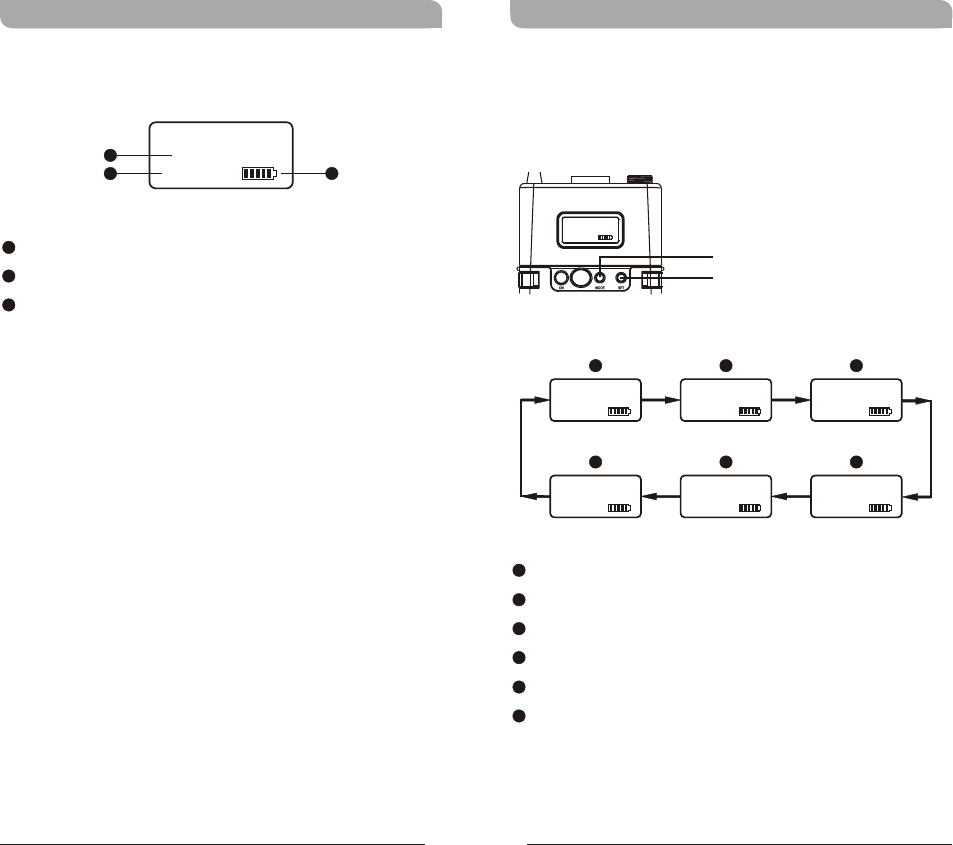
LCD Screen
AF (audio) MUTE
Transmitter Battery Meter
1414
1515
1616
Group and Channel
Frequency
Sensitivity Level
RF Output Power
Frequency Band
Parameters Lock & Unlock Status
BB
AA
CC
DD
EE
FF
!Press “MODE” button to access one of the six
parameters below.
MODE
SET
07 05 07 05
CH GRP
F
F
E
E
A
A
D
D
B
B
C
C
67
Bodypack Transmitter Bodypack Transmitter
07 05
GRP CH
Low
RF POWER
6UA2
BAND
MIC-L
AF GAIN
868.125
FREQUENCY
MHz
ON
LOCK
!Frequency Band, Group & Channel and Frequency
are factory pre-set, thus, its parameter values are
displayed after it is ACT synced. Values cannot be
changed.
( )Frequency Band
( )Group and Channel
( )Frequency
07 05
GRP CH
8A
BAND
868.125
FREQUENCY
MHz
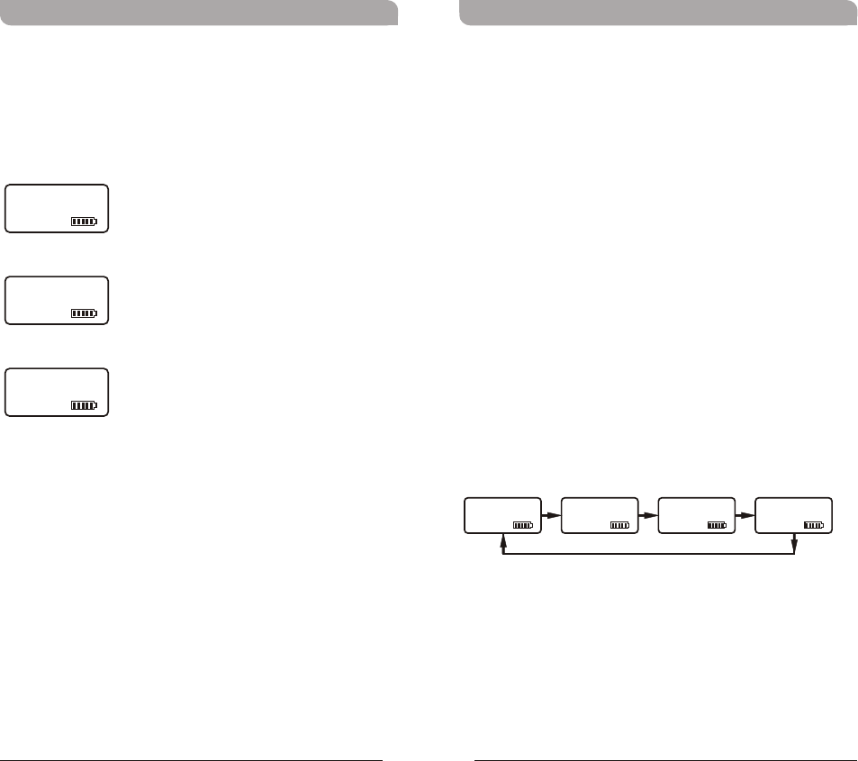
Setting Input Sensitivity Level
!4 Selectable Sensitivity Levels: LINE、MIC-L
(MICROPHONE-LOW)、MIC-M (MICROPHONE-
MID)、MIC-H (MICROPHONE-HIGH).
!Press MODE button until mode
appears.
!Press SET button once to activate function.
!Press SET button to select the desired sensitivity
level.
!Press MODE button to confirm and save the
change.
!The higher the sensitivity level, the lower the
dynamic range of input signals. Meanwhile noise
will increase, and the feedback problem will be
getting more serious.
NOTE: Guitar setting is recommended at LINE level.
AF GAIN
89
Bodypack Transmitter Bodypack Transmitter
LINE
AF GAIN
MIC-L MIC-M MIC-H
AF GAIN AF GAIN AF GAIN
Setting RF Output Power
!2 RF Output Power Levels: High and Low.
!Press MODE button until RF POWER LOW or RF
POWER HIGH mode appears.
!Press SET button once to activate function.
!Press SET button to select the desired RF output
power.
!Press MODE button to confirm and save the
change.
Low
RF POWER
High
RF POWER
10 11
Bodypack Transmitter Bodypack Transmitter
Setting LOCK
!Setting LOCK can be switched to On or Off mode.
!Press MODE button until LOCK ON or LOCK OFF
mode appears.
!Press SET button to select the desired parameter.
!Press MODE button to confirm and save the
change.
NOTE: Once locked, all six (6) parameter values
cannot be changed.
LOCK
OFF
LOCK
ON
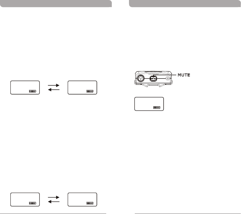
MUTE Control Set-Up
MUTE control enables audio to be muted or un-
muted temporarily.
Press MUTE button to mute audio temporarily.
Parameter values can be changed and ACT sync
activate during this MUTE mode.
Press MUTE button to un-mute.
!
!
AF INPUT
AF MUTE
MUTE
External mute connector
PoFF
RF POWER
Bodypack Transmitter Bodypack Transmitter
12 13
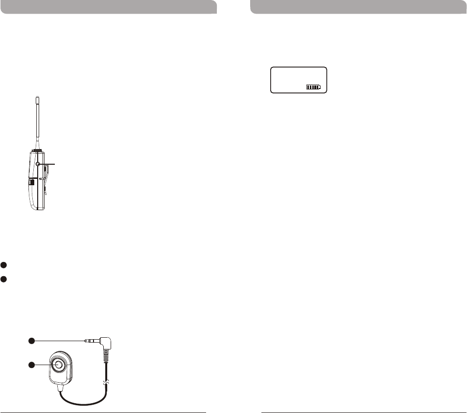
External Mute Connector Power Button
MJ-70 External Mute Switch (optional)
!External mute connector is a 3.5mm jack. When
an external mute switch cable, MJ-70 (optional) is
connected, user can manually mute and un-mute
the audio temporary.
!Press and hold for 2 seconds to power on & off.
3.5mm jack.
External mute switch on/off button.
NOTE: Plug in the device before power on the
bodypack transmitter.
1717
1818
1717
1818
AUDIO
SHIELD
4
3
2
1
PIN
SHIELD
AUDIO
BIAS
3
4
PIN
1
2
AUDIO
SHIELD 1
4
3
2
PIN
SHIELD
AUDIO
3
21PIN
4
3
2
1
SHIELD
AUDIO
1
3
4
2
PIN
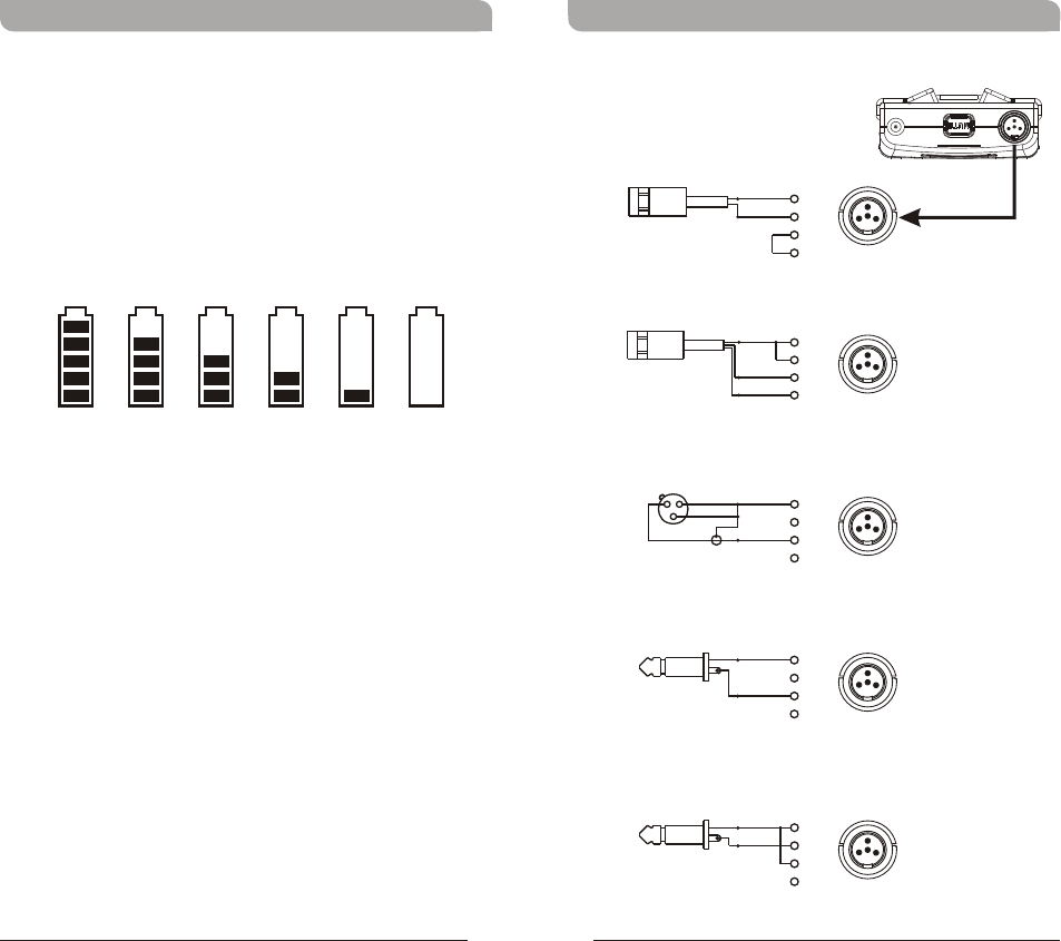
AF Input Connections
(1) 2-Wire Electret condenser
microphone Capsule
(2) 3-Wire Electret condenser microphone Capsule
(3) Dynamic Microphone
(5) Line-in (Impedance 8KΩ ATT. 10dB)
(4) Electric Guitar
1
3
4
2
1
3
4
2
1
3
4
2
1
3
4
2
1
3
4
2
Bodypack Transmitter Bodypack Transmitter
14 15
“PoFF” - Power Off:
When the power switch is turned off, the LCD will
show “PoFF” (for Power Off) first and then the
system will shut down and no further messages will
be displayed.
100% 80% 60% 40% 20% 10%
Battery Status
Indicates the power remaining in the transmitter
battery. When the battery has less than 10% power
remaining it must be replaced or recharged. If an
under voltage condition continues, the LCD will show
“PoFF” and the system will shut down to prevent
being overly discharged.
16 17
Bodypack Transmitter
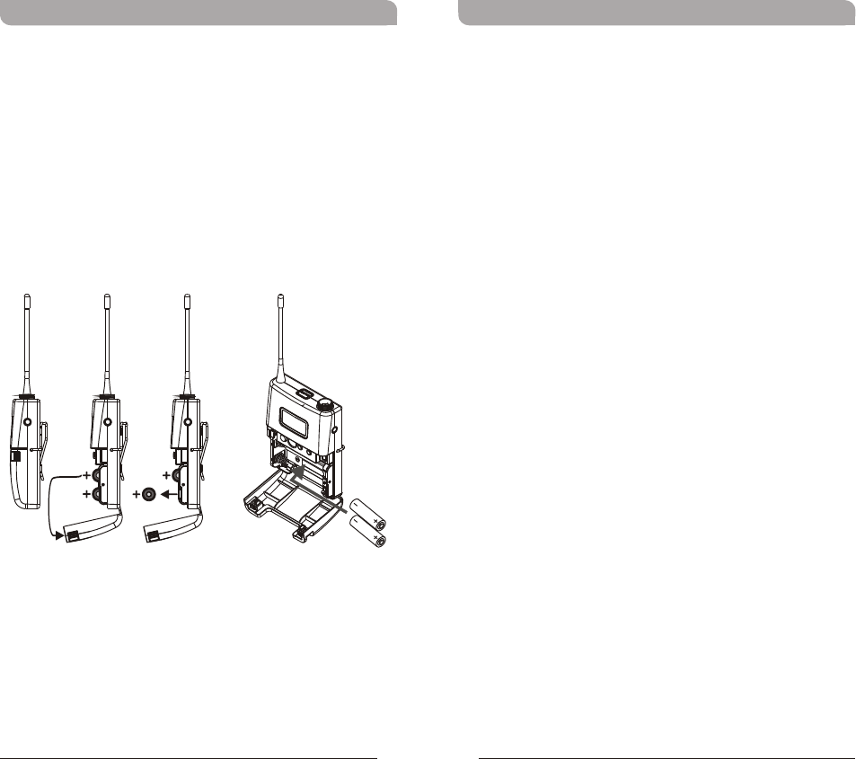
Battery Removal and Installation
Pushing down both snap locks on the sides to open
battery compartment cover. Take out the two
batteries. (Figure 3)
Insert two fresh AA batteries (alkaline type is
recommended) into the battery compartment
according to the correct polarity (- and +) as shown
in (Figure 4). Then close the battery compartment
cover tightly.
Caution:
Remove the batteries if unused for a long period of
time to prevent battery leakage, corrosion and
causes possible damage to electronics.
(Figure 4)(Figure 3)
Federal Communication Commission Interference Statement
This equipment has been tested and found to comply with the limits for a Class B digital device, pursuant to Part 15 & 74 of the FCC Rules. These limits are
designed to provide reasonable protection against harmful interference in a residential installation.
This equipment generates, uses and can radiate radio frequency energy and, if not installed and used in accordance with the instructions, may cause harmful
interference to radio communications. However, there is no guarantee that interference will not occur in a particular installation. If this equipment does cause
harmful interference to radio or television reception, which can be determined by turning the equipment off and on, the user is encouraged to try to correct the
interference by one of the following measures:
. Reorient or relocate the receiving antenna.
. Increase the separation between the equipment and receiver.
. Connect the equipment into an outlet on a circuit different from that to which the receiver is connected.
. Consult the dealer or an experienced radio/TV technician for help.
FCC Caution: To assure continued compliance, any changes or modifications not expressly approved by the party responsible for compliance could void the
user's authority to operate this equipment. (Example - use only shielded interface cables when connecting to computer or peripheral devices).