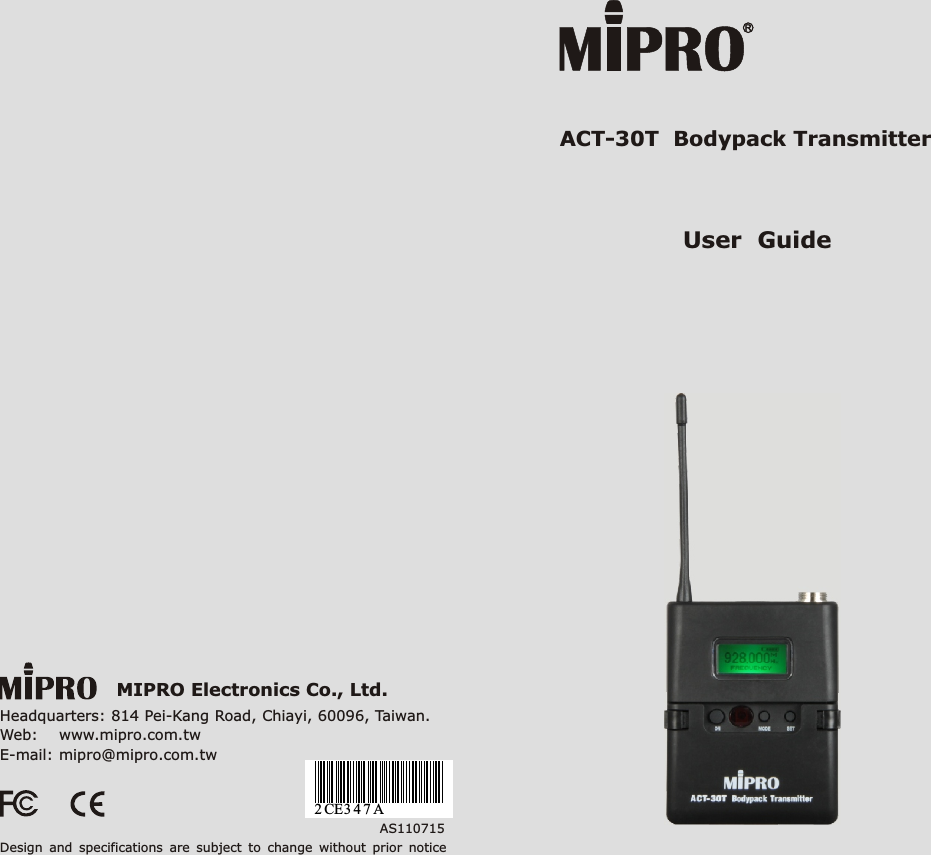
Mipro Electronics Co ACT30T Bodypack Transmitter User Manual ACT 30T 2CE347A 20110715
Mipro Electronics Co Ltd Bodypack Transmitter ACT 30T 2CE347A 20110715
UserManual.wiki
>
Mipro Electronics Co
>
ACT30T User Manual
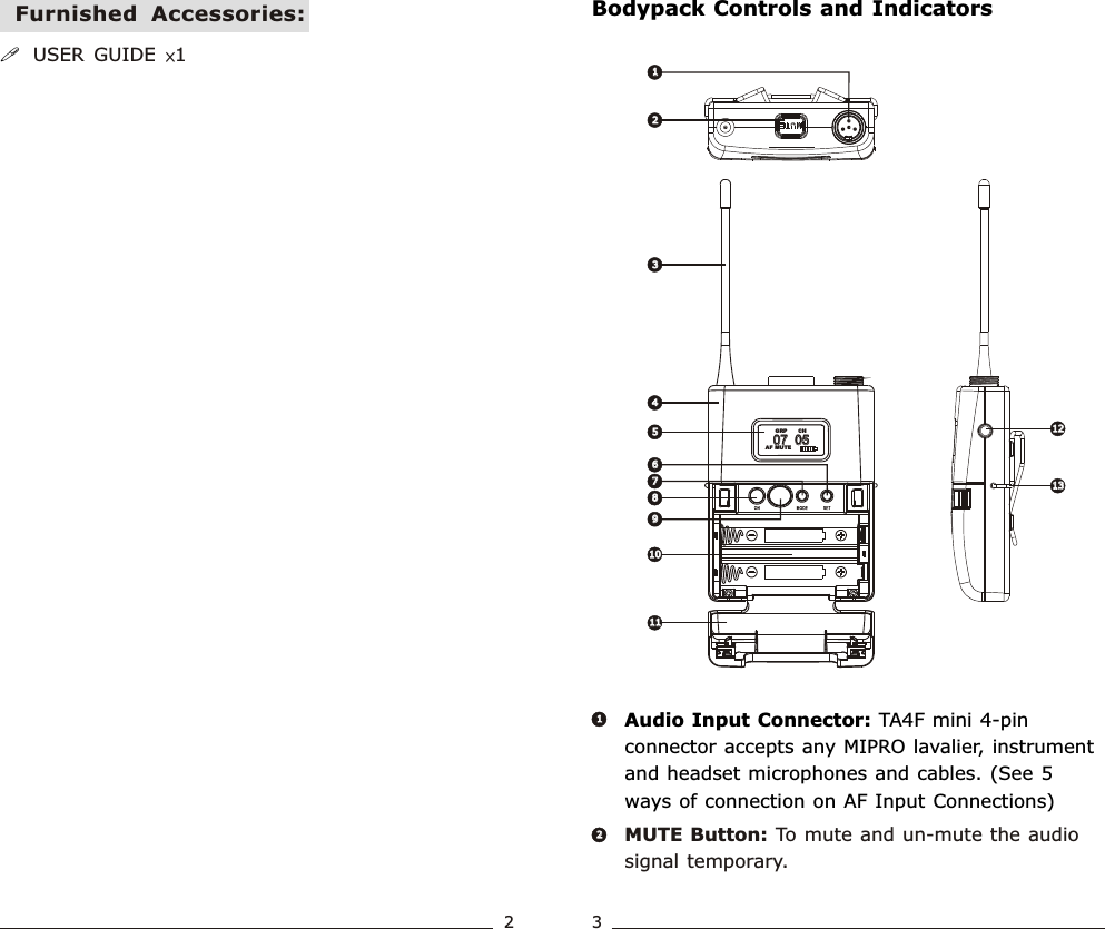
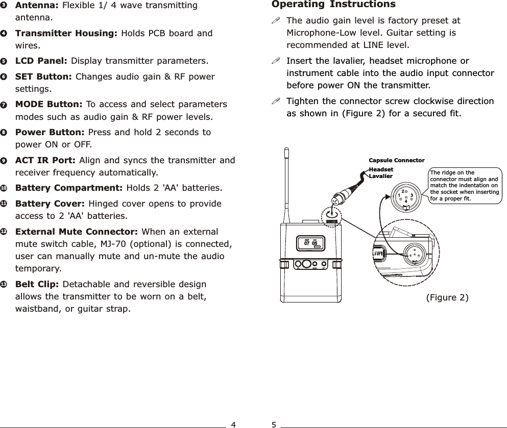
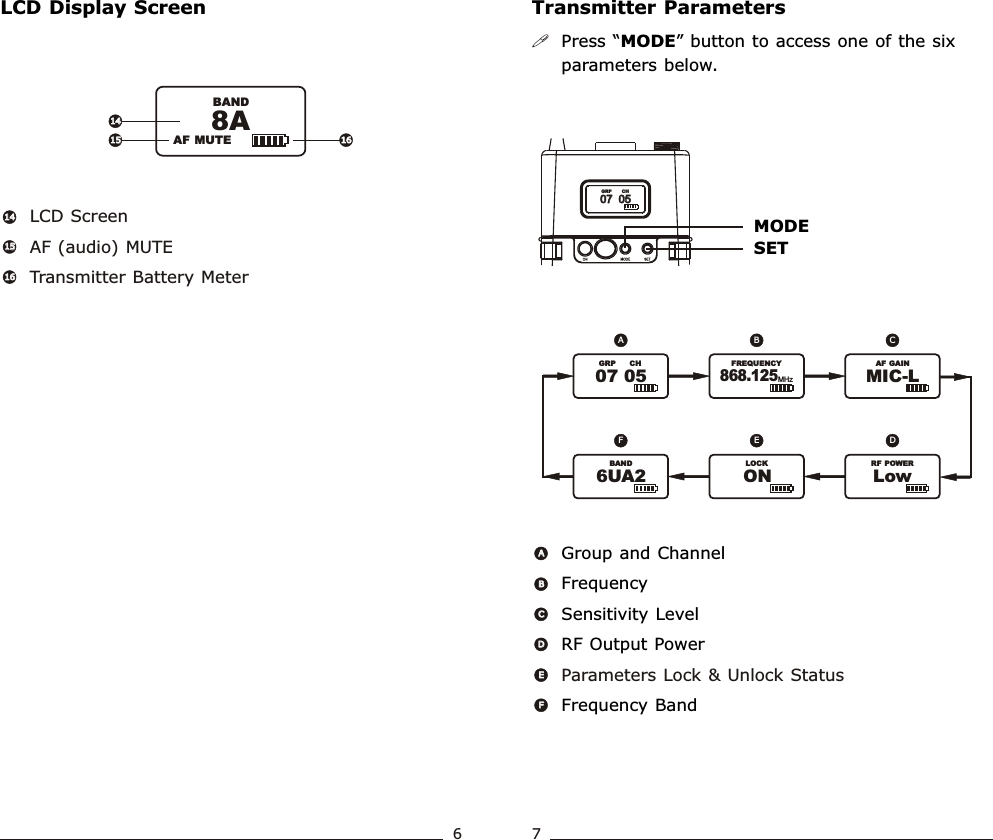
Users Manual
Navigation menu
Upload a User Manual
Namespaces
Wiki Guide
HTML
PDF
Info
Views
User Manual
Discussion / Help
Navigation