Mipro Electronics Co ACT70HN71A71 Wideband Handheld Transmitter User Manual ACT 70H 2CE466A 20121015
Mipro Electronics Co Ltd Wideband Handheld Transmitter ACT 70H 2CE466A 20121015
Users Manual
ACT-70H
Handheld Transmitter
Wideband
User Guide
MIPRO Electronics Co., Ltd.
Headquarters: 814 Pei-Kang Road, Chiayi, 60096, Taiwan
Web: www.mipro.com.tw
E-mail: mipro@mipro.com.tw
AS121015
Design and specifications are subject to change without prior notice
2 CE4 6 6 A

1 Features
3 Handheld Controls and Indicators
5 O
16 Setting MUTE
17 General Tips for Improving System
Performance
perating Instructions for Insertion &
Removing Battery
6 Patented Protection Cover
8 LCD Display Screen
9 How to Setup Transmitter Parameters
14 Battery Status
Wideband Handheld Transmitter
01
Contents
Wideband Handheld Transmitter
!Innovatively designed housing in MIPRO's
aesthetics and ergonomic style.
!Perfect combination of audio and wireless
transmission technology creates perfect sound
quality.
!Patented design of the grille and battery housing
being integrated. It's easy to screw the grille to
open the battery compartment and install 2 AA
batteries.
!The unique flat top multi-layered steel grille for
condenser capsules and round top for dynamic
capsules protect the capsule against impact and
pop noise. The upper grille is able to be
detached easily for cleaning and hygiene
practices.
!The interior grille with fine metal mesh instead
of sponge foam minimizes pop noise and
effectively ensures sound clarity.
!Patented dual-end shock-mount capsule
suspension design virtually eliminates the
vibrations and handling noises.
!Premium detachable condenser or dynamic
microphone capsule module options
!True condenser capsule exhibits high fidelity,
wide dynamic range, fast transient responses,
low feedback howling, accurate sound image
characteristics, transparent sound quality, and
sustains maximum SPL.
!Enhanced low handling noise and vibration
suspension designed dynamic microphone
capsules for option.
Features
Handheld Controls and Indicators
!Backlit LCD displays working channel, battery
status, encryption status, RF, and audio levels.
!The bottom housing, where high-efficiency
antenna is integrated inside, embedded with
power switch, mute button and setup button for
programmed gain, limiter, low cut and RF output
power.
!The bottom housing is covered by patented end-
cap with color-coded channel identification clips.
Detach the end-cap to operate setup button.
Reverse the end-cap to shield power switch and
operate the mute button during operation.
!High efficiency and low spurious emissions
transmitting circuit is applied. An interference-
free working channel can be synchronized
automatically and quickly without any error by
MIPRO's patented ACT™ function.
Wideband Handheld TransmitterWideband Handheld Transmitter
23
11
22
33
88
99
44
1010
1111
66
77
55
01 01
GROUP CHAN
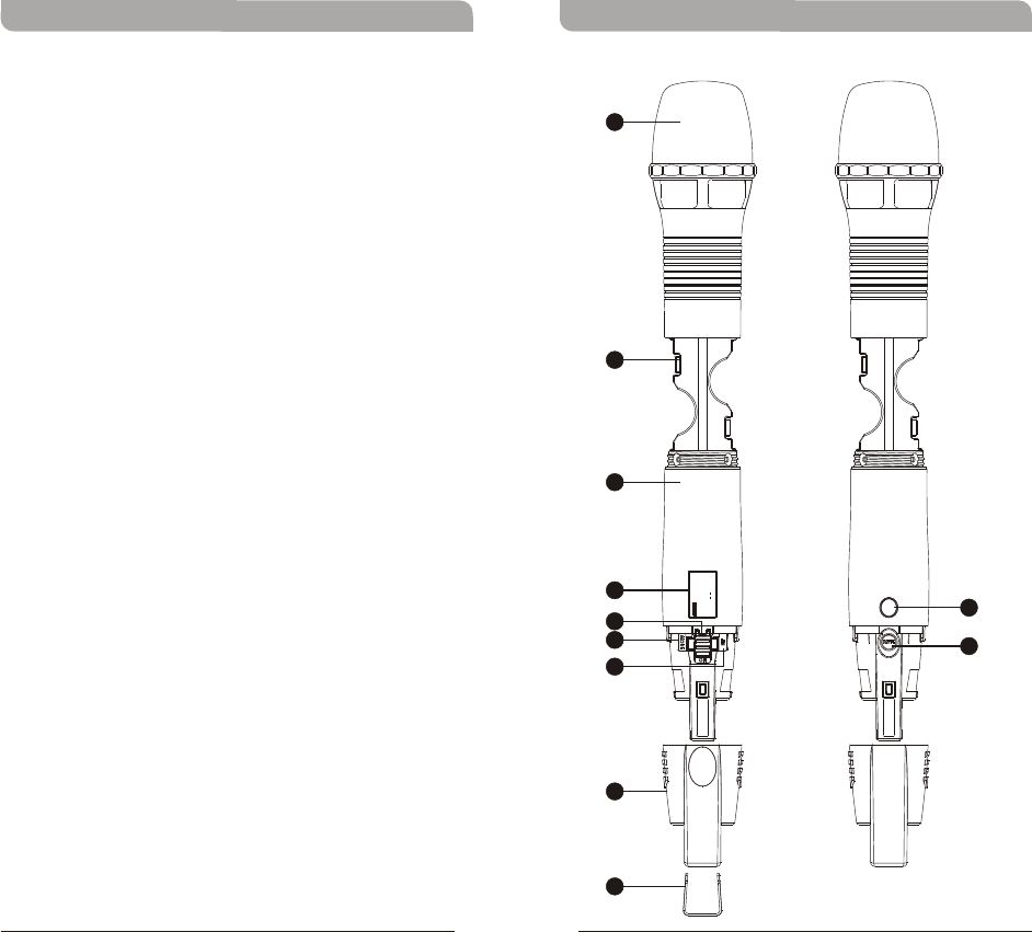
Capsule Module: Protects detachable
microphone capsule module and internal foam
prevents breathing, wind and POP noises.
Battery Compartment: Holds 2 'AA' batteries.
Housing: Protects transmitter PCB, battery
compartment and batteries.
LCD Panel: Displays transmitter parameters.
Power On/Off Switch: Slides the power switch
to the “ON” position for use or to the “OFF”
position when not in use.
MODE Button: Allows access to 6 available
functions displaying in LCD panel.
SET Button: Parameter selection button.
ACT Infrared (IR) Port: Receives signals from
receiver to synchronize frequencies.
MUTE Button: To mute and un-mute the audio
signal temporary.
Protection Cover: Protects power switch and
prevents user has direct access to power switch.
Channel ID Clip: For channel identification
(Optional)
1
2
3
4
5
6
7
8
9
10
11
Wideband Handheld TransmitterWideband Handheld Transmitter
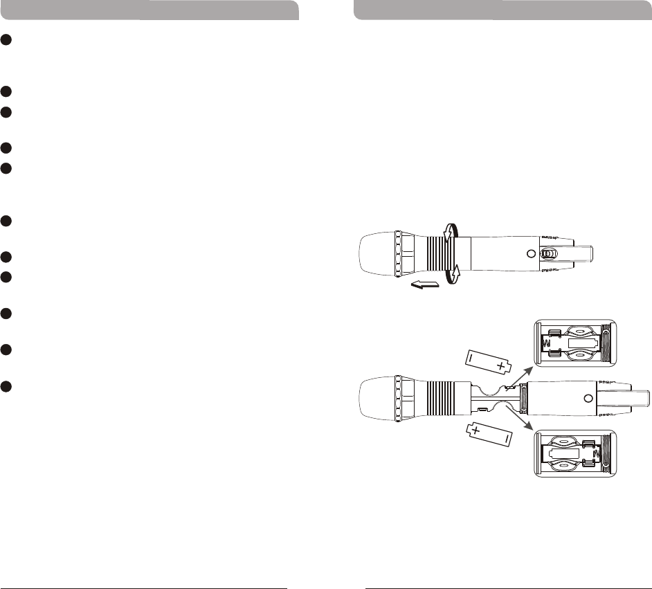
Operating Instructions for Insertion &
Removing Battery
Caution:
Remove the batteries if unused for a long period
of time to prevent battery leakage, corrosion and
causes damage to electronics.
!
!
!
Turn the microphone housing and pull it toward
capsule grille to expose battery compartment.
Insert two new AA alkaline batteries in the
battery compartment with correct polarity
orientation.
Turn power switch to ON position after battery
installation. If LCD does not lit, please check
battery polarity or change to fresh batteries.
45
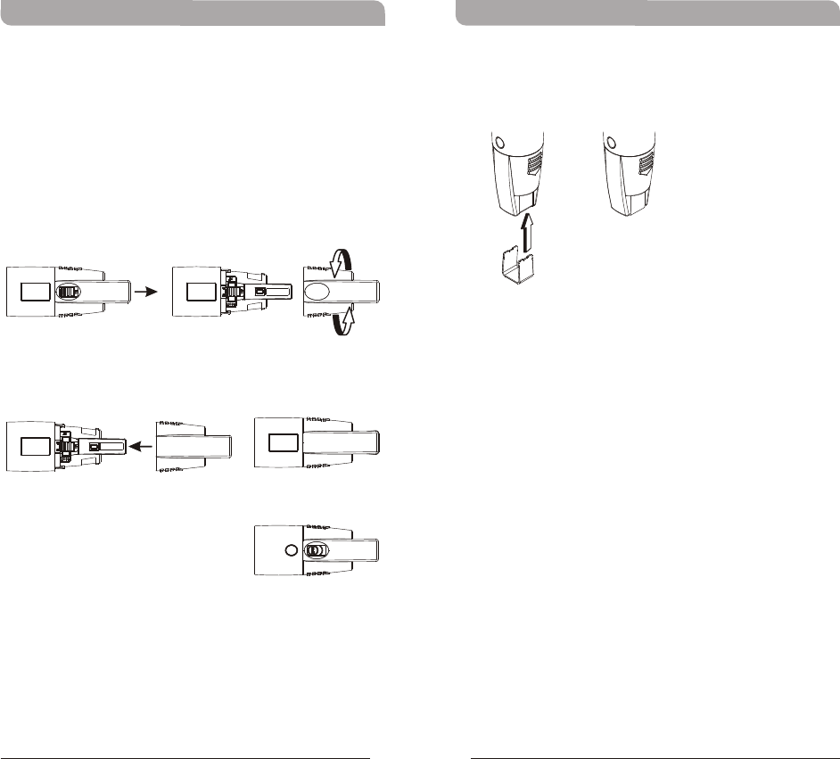
!Channel identification clip can be attached to the
bottom of protection cover.
Protection cover's patented design protects
accidental access to power switch and its rugged
material and snug fit offer protection to both power
switch and PCB during accidental drop.
Steps:
!Remove protection cover and turn it 180-degree.
!Install the protection cover after turning will
cover up power switch.
Mute function is open for easy acsess.
!When power is off, reverse-installation of
protection cover will turn on the switch
automatically. To turn off the system, remove
the cover to turn off.
!Protection cover must be attached during
operation for full protection.
Patented Protection Cover
Wideband Handheld TransmitterWideband Handheld Transmitter
67
FFEE
AA
DD
BBCC
LCD Screen for function display
AF (audio) MUTE
Transmitter Battery Meter
1212
1313
1414
1212
1414
7UA
BAND
AF MUTE
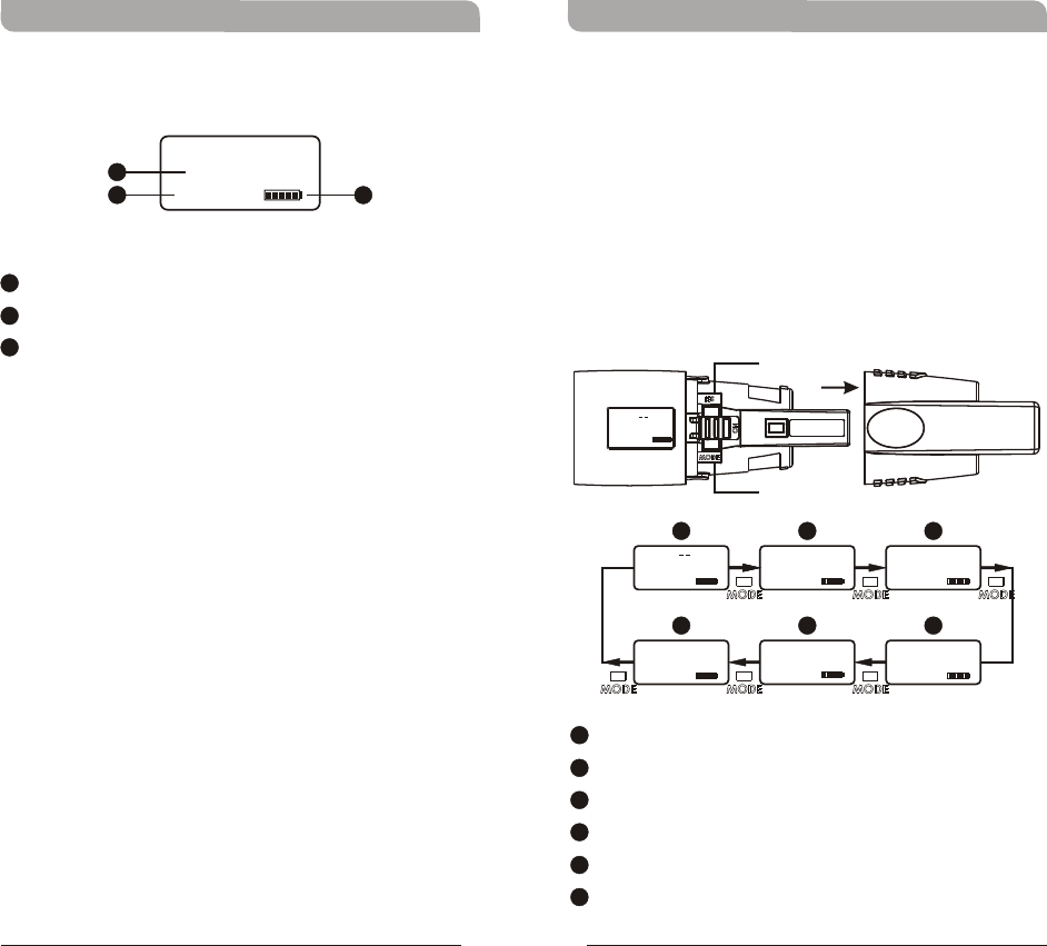
How to Setup Transmitter ParametersLCD Display Screen
1313
!Remove protection cover to expose MODE
button and SET button.
!MODE Button:
Press “MODE” button to access one of the six
functions below.
!SET Button:
Press “SET” button and LCD wills start flashing.
During flashing, press SET button to change
parameters.
Wideband Handheld TransmitterWideband Handheld Transmitter
Group and Channel
Frequency
Sensitivity Level
RF Output Power
Frequency Band
MUTE Mode
BB
AA
CC
DD
EE
FF
89
MODE
SET
01 01
GROUP CHAN
01 01
GROUP CHAN
775.275MHz
FREQUENCY
0 dB
AF GAIN
7UA
BAND
MANUAL
MUTE MODE
RF-LOW
RF POWER
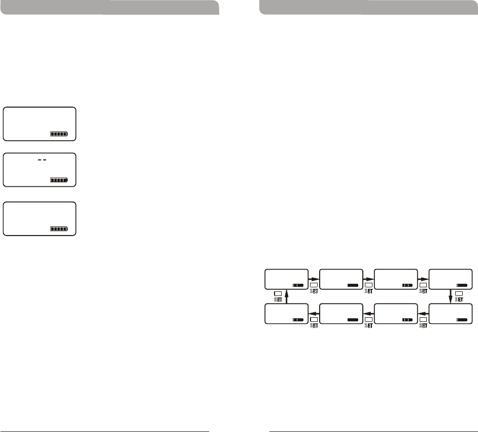
!Frequency Band, Group & Channel and
Frequency are factory pre-set, thus, its
parameter values are displayed after it is ACT
synced. Values cannot be changed.
( )Frequency Band
( )Group and Channel
( )Frequency
Wideband Handheld TransmitterWideband Handheld Transmitter
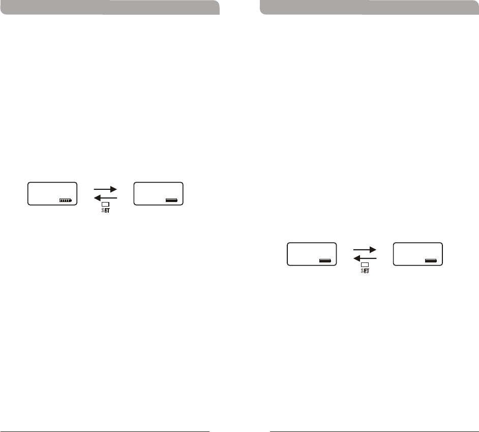
Setting Input Gain Level
!Selectable AF GAIN between 6dB to -6dB with
3dB parameter up or down selection.
!Press MODE button until AF GAIN mode
appears.
!Press SET button once to activate function.
!Press SET button to select the desired
sensitivity level.
!Press MODE button to confirm and save the
change.
!The higher the sensitivity level, the lower the
dynamic range of input signals. Meanwhile noise
will increase, and the feedback problem will be
getting more serious. Please make sure
sensitivity level is set at proper level.
10 11
7UA
BAND
775.275MHz
FREQUENCY
01 01
GROUP CHAN
0 dB
AF GAIN
3 dB
AF GAIN
6 dB
AF GAIN
3 dB
AF GAIN
-6 dB -3 dB
AF GAIN AF GAIN
-3 dB
AF GAIN
0 dB
AF GAIN
Setting RF Output Power
!2 RF Output Power Levels: RF-HI and RF-LOW.
!Press MODE button until RF POWER mode
appears.
!Press SET button once to activate function.
!Press SET button to select the desired RF output
power.
!Press MODE button to confirm and save the
change, or LCD will stop flashing after 5 seconds
and parameter will be saved.
Wideband Handheld TransmitterWideband Handheld Transmitter
12 13
MUTE MODE
!MUTE MODE: Select from MANUAL and
DISABLE.
!Press MODE button until MUTE MODE appears.
Press SET button once, the LCD screen starts
flashing to denote it is ready to accept mode
changes. Press SET button to change between
MANUAL and DISABLE in cycle. Press MODE
button to confirm and save the change, or LCD
will stop flashing after 5 seconds and parameter
will be saved.
!MUTE button is operable when MUTE MODE is
set in MANUAL mode.
!MUTE button is not operable when MUTE
MODE is set in DISABLE mode.
RF-HI
RF POWER
RF-LOW
RF POWER
DISABLE
MUTE MODE
MANUAL
MUTE MODE
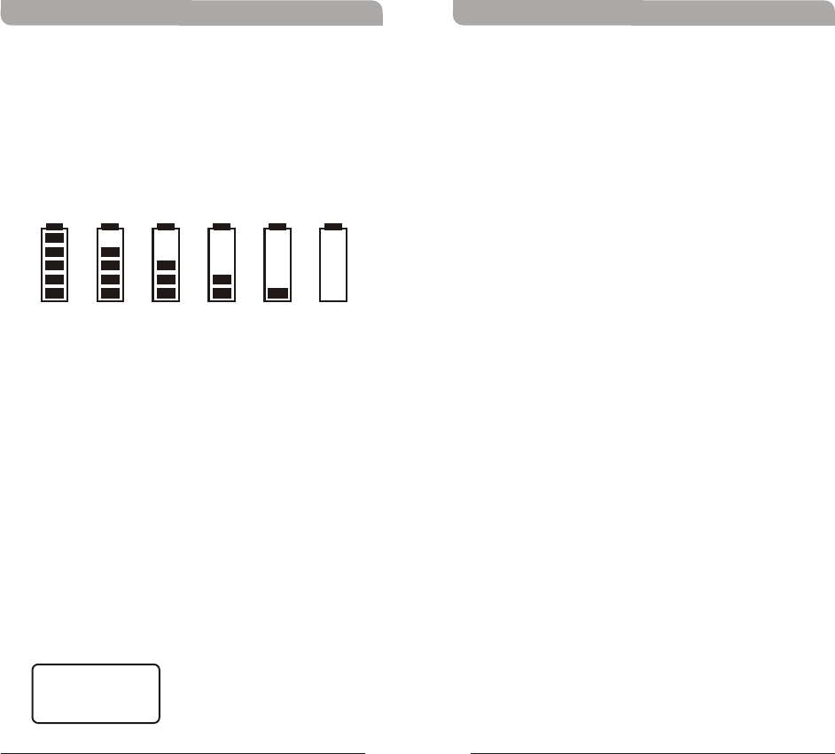
!When the battery has less than 10% power
remaining, display will start flashing and
batteries must be replaced immediately. If an
under voltage condition continues, the LCD will
show “OFF...” and the system will shut down.
Battery Status
100% 80% 60% 40% 20% 10%
Wideband Handheld TransmitterWideband Handheld Transmitter
!Turn the power switch to ON position where
transmitter will be activated and LCD will lit up.
!Turn the power switch to OFF position to shut
down the transmitter.
!When the power switch is turned off, the LCD
will show “OFF...” (for Power Off) first and then
the system will shut down and no further
messages will be displayed.
Power Button
ERR Message
!When “ERR” appears in the display it indicates
that an operational error has occurred. Please
refer to the following codes to diagnose which
error you are experiencing.
ERR no01 EEPROM is not being programmed or
internal data error.
ERR no02 For testing only.
ERR no03 The frequency you want to program is
above the switching bandwidth of the
transmitter. Use a receiver with an
appropriate frequency group. (At this time
the microphone is still operating and the
frequency remains unchanged. To clear the
displayed "ERR" message, switch the
handheld transmitter off and on again.)
ERR no04 The frequency you want to program is
below the switching bandwidth of the
transmitter. Use a receiver with an
appropriate frequency group. (At this time
the microphone is still operating and the
frequency remains unchanged. To clear the
displayed “ERR” message, switch the
handheld transmitter off and on again.)
!“Group” & “Channel” : When both the group
and channel numbers are displayed, it means
that you are using the pre-programmed
frequency of the receiver.
!“Channel” Only : If “Channel” only is
displayed, it means that you are using a
frequency which is not pre-programmed.
14 15
OFF...
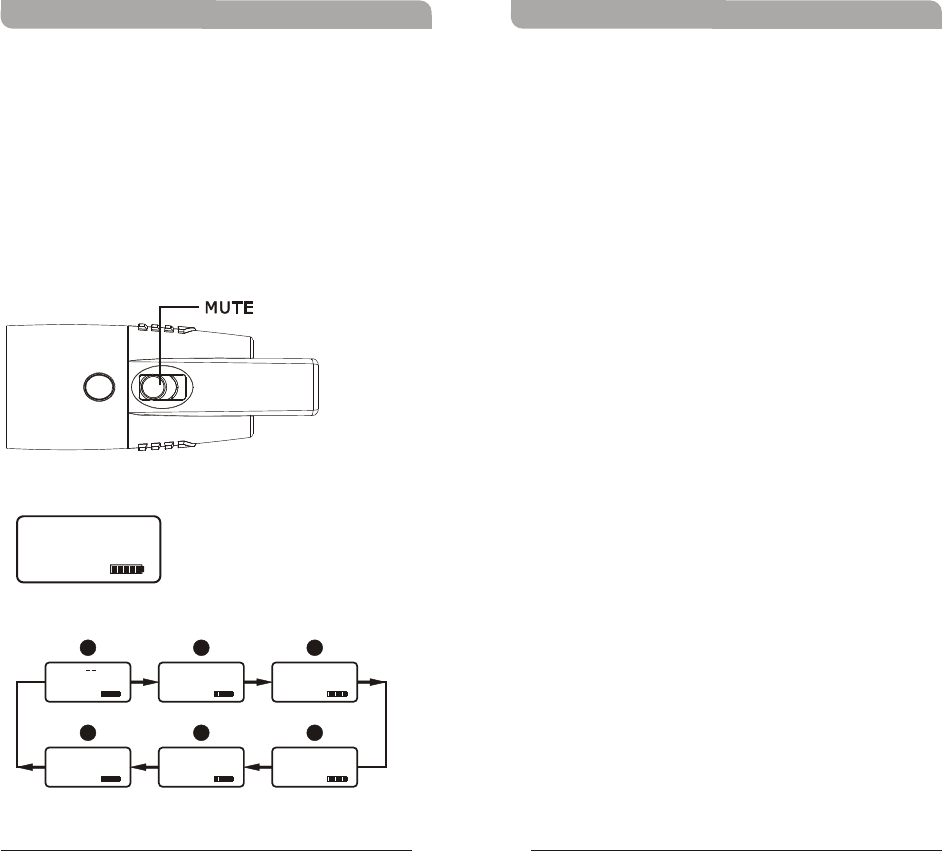
Setting MUTE
!Press MUTE button to enter MUTE mode.
!Under MUTE mode, press MUTE button to exit
MUTE mode.
!MUTE button is not operable when MUTE
MODE is set in DISABLE mode.
Wideband Handheld TransmitterWideband Handheld Transmitter
MUTE
AF MUTE
AF INPUT
MUTEMUTE
General Tips for Improving System
Performance
1. Performer should avoid holding the microphone over
or near the antenna section as this will deteriorate
transmission efficiency. Severe deterioration if
performer directly covers up the antenna section with
both hands.
2. Many performers tend to hold the microphone by the
top grille. Unfortunately, this position seriously
degrades both the sound quality and directionality of
a microphone. Even the most expensive microphones
will have its original sound quality compromised by
this method. Grabbing a microphone by the grille will
isolate the capsule's acoustic resonance circuit and or
change the capsule resonator's frequency. This
results in an inferior performance in both frequency
response and the separation of directionality. In
addition, a palm's sound-focusing effect will tend to
strengthen resonances in certain frequencies and can
cause unwanted echo.
3. A proper technique is required for using directional
microphones because the distance between the
microphone and your mouth has a significant impact
on sensitivity and performance. There is an inverse
relationship between microphone sensitivity and the
distance from the mouth to the microphone.
Consequently, performers with a ''weaker'' sound
level cannot expect to hold the microphone too far
away from their mouth and compensate by turning
up the amplifier volume to increase the sound level
as this can easily cause echo or feedback. In
contrast, performers with a ''louder'' sound level
should not hold the microphone too close as this can
easily result in distortion by causing the amplifier
system to be overloaded.
16 17
FFEEDD
AABBCC
AF MUTE AF MUTE AF MUTE
01 01
GROUP CHAN
775.275MHz
FREQUENCY
0 dB
AF GAIN
AF MUTE
7UA
BAND
AF MUTE
MANUAL
MUTE MODE
RF-LOW
RF POWER
AF MUTE
4. Furthermore, a large-diaphragm directional
microphone has a very distinct proximity effect.
When the microphone is close to the mouth, the
bass response is strengthened as the distance
gets closer. Therefore, if a performer's sound is
insufficient in bass, they can hold the
microphone closer and use the proximity effect
to help compensate for the lower bass level.
Conversely, if a performer's voice is too heavy in
the bass register, increasing the distance
between the microphone and their mouth will
decrease the proximity effect and reduce the
bass response, thus making their voice become
clearer and brighter.
5. It is recommended to keep the grille and sponge
windscreen clean to avoid any substance blocking
the proximity effect of the microphone.
Wideband Handheld TransmitterWideband Handheld Transmitter
Disposal
2005-08 -132005-08 -13
Dispose of any unusable devices or
batteries responsibly and in accordance
with any applicable regulations.
Disposing of used batteries with
domestic waste is to be avoided!
Batteries / NiCad cells often contain
heavy metals such as cadmium(Cd),
mercury(Hg) and lead(Pb) that makes
them unsuitable for disposal with
domestic waste. You may return spent
batteries/ accumulators free of charge
to recycling centres or anywhere else
batteries/accumulators are sold.
By doing so, you contribute to the
conservation of our environment!
THIS DEVICE COMPLIES WITH PART 74 OF THE FCC
RULES AND RSS-123 ISSUE2 OF CANADA.
OPERATION IS SUBJECT TO THE FOLLOWING TWO
CONDITIONS:
(1) This device may not cause interference.
(2) This device must accept any interference,
including interference that may cause undesired
operation of the device. This equipment complies
with FCC RF radiation exposure limits set forth for
an uncontrolled environment.
& IC - ID
18 19