Mipro Electronics Co ACT80T Digital Bodyback Transmitter User Manual ACT 80T 2CE464A X3 20120901
Mipro Electronics Co Ltd Digital Bodyback Transmitter ACT 80T 2CE464A X3 20120901
UserManual.wiki
>
Mipro Electronics Co
>
ACT80T User Manual
Users Manual
Navigation menu
Upload a User Manual
Namespaces
Wiki Guide
HTML
PDF
Info
Views
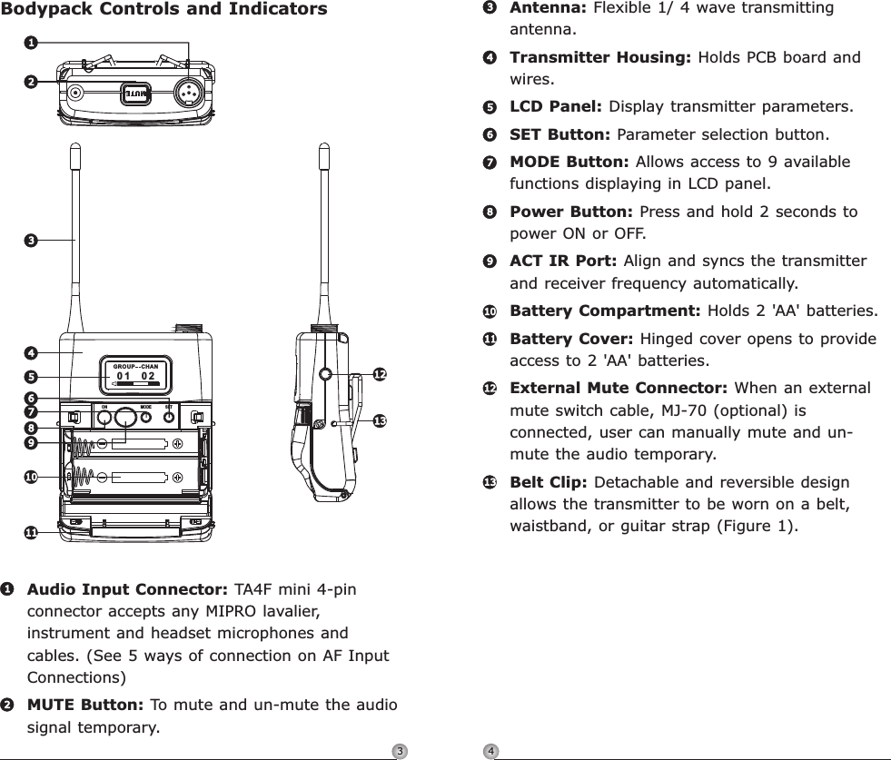
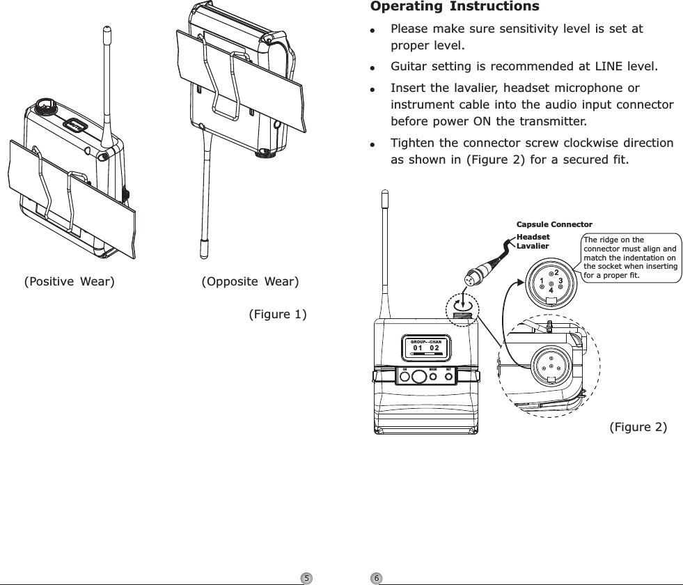
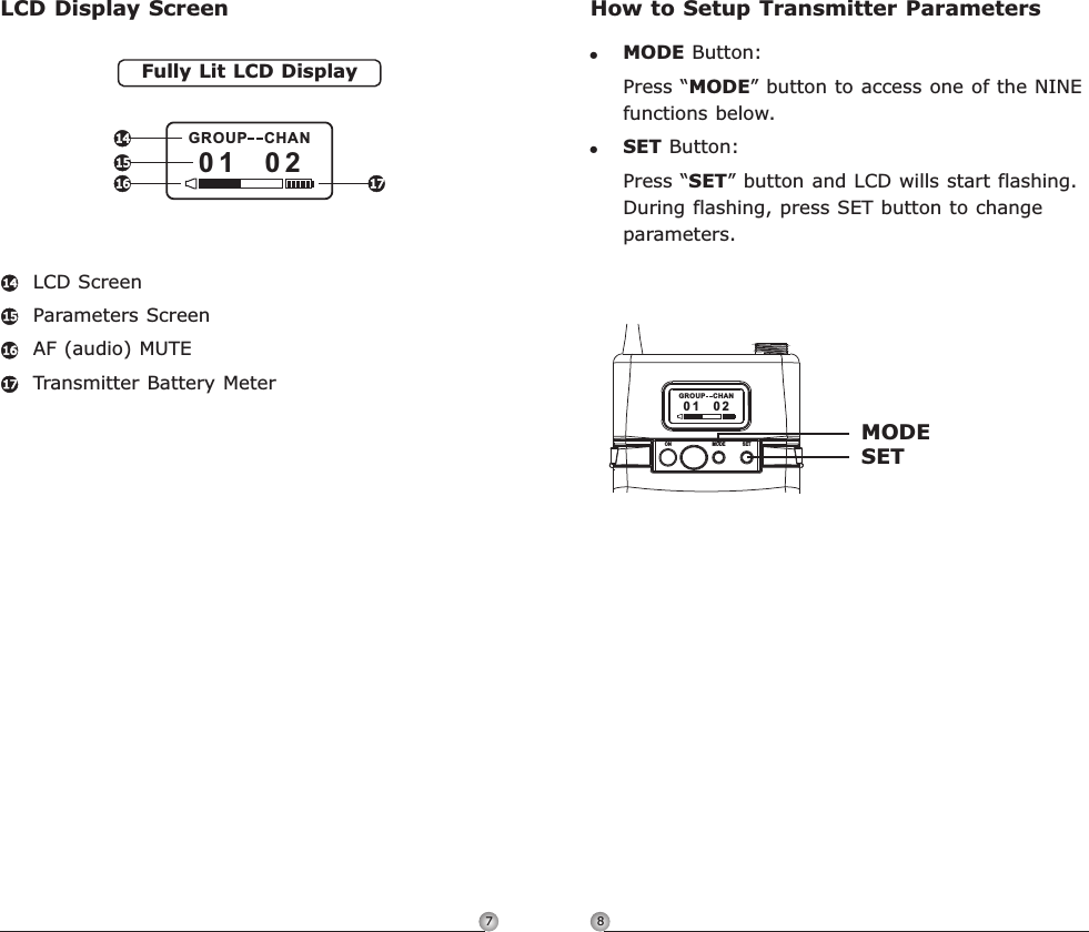
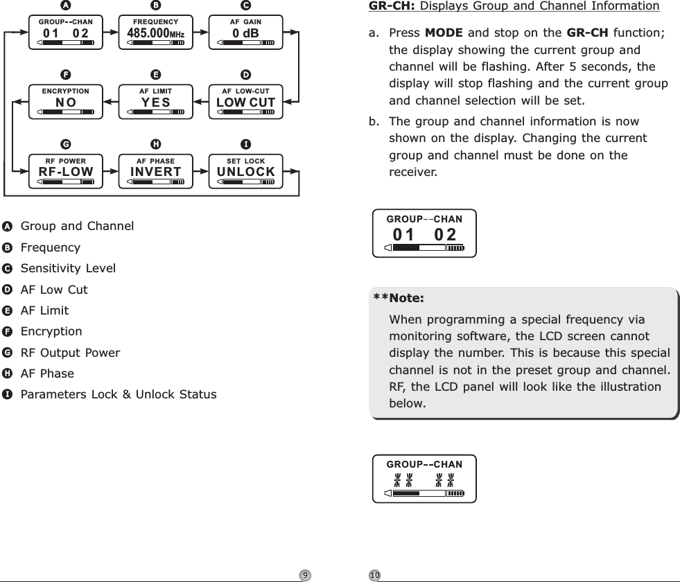
User Manual
Discussion / Help
Navigation