Mipro Electronics Co MI808 Wireless Microphone System User Manual MI 808T 2CE180
Mipro Electronics Co Ltd Wireless Microphone System MI 808T 2CE180
User Manual
UserGuide
MI-808TStereoTransmitter
2CE180
ElectronicsCo.,Ltd.
Headoffice:814,Pei-KangRoad,Chiayi,600,Taiwan.
Taipeioffice:5,Lane118,Sung-tehRoad,100,Taipei,Taiwan.
Web-http://www.mipro.com.tw
E-mail:@mipro.com.twmipro
1
0
Index StereoTransmitter
1.Preface:1
3
4-8
8
2.FeaturesofMI-808T:
3.Glossary:
4.OperatingMI-808R:
5.ImportantNotes:
2
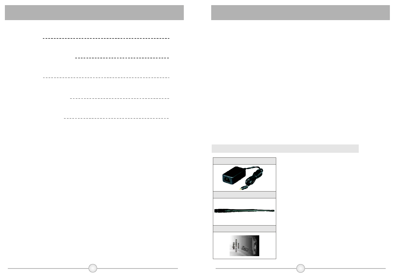
YourPackageContainstheFollowingAccessories﹕
ThankyouforchoosingMIPRO'sfinestminiaturestereotransmitter.
Thissystemisengineeredtosatisfyallworkrequirementsinproaudio
applications,suchasmusicians,performers,anddirectors.
Togetthemostoutofyoursystem,pleasereadtheapplicablesection
thoroughlyinthisguidebeforeyouattempttousethesystem.
CharacteristicofMI-808T:
MI-808Tisawirelessmonitoringsystemdesignedspeciallyforpeoplein
stageperformanceandbroadcasting.Mainpurposeofthissystemistoallow
peopletolistentotheiraudiosourceseasilyinsteadofviacomplicatedaudio
cablesormonitoringspeakers.Inaddition,MI-808Tcanserveasconference
PAsystemormulti-lingualtranslator.Toincreaseaudioquality,S/Nratio,and
dynamicrange,MIPROadopts"DynamicSignalProcessingTechnology"to
limitnoiseleveltoitsminimal.
1.Preface:
Antenna1×
UserGuide
Switchingpowersupply
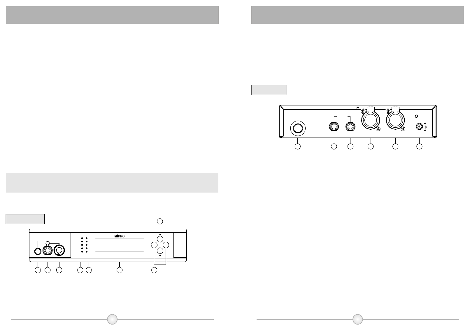
FrontPanel:
RearPanel:
(1)PowerSwitch:Toturnonandoffthepowersupplyforthesystem.
(2)HeadphoneOutputSocket:AllowlinkingwithstereoHeadphonetomonitoroutput
signal.
(3)VolumeControl:AdjustthevolumeofstereoHeadphonebycounterclockwise
direction.
(4)LeftLevelIndicator,includinglimitorindicator.
(5)RightLevelIndicator,includinglimitorindicator.
(6)LCDDisplayPanel:Displaythedetailsofsettingandspecification.
(7)ModificationFunctionKey:Modifysettingfunction.
(8)FunctionSelectingKey:Selectsettingfunction.
(9)TransmittionSignalOutputConnector:InstalltransmittionAntennas.
(10)LeftUnbalancedOutputLevelSocket.
(11)RightUnbalancedOutputLevelSocket.
(12)LeftInputLevelSocket:Mixedusedforbalancedandunbalancedinput.
(13)RightInputLevelSocket:Mixedusedforbalancedandunblancedinput.
(14)DCPowerInputSocket:Toconnect15VDCpowerinputSocket.Connectthe
centerpoleofthejacktopositivevoltage.
23
6
POWER HEADPHONE VOLUME
LIM
-12
-20
-30
-40
SOURCE
+
-
LR
MI-808TStereoTransmitter
ANTENNA
DCIN(15~18V)LR
LOOPOUT
AFIN(L) AFIN(R)
75321
8
4
9 10 11 12 13 14
MI-808TisanUHFstereotransmittorwithpreset16non-interferece
frequenciesineach24MHz.Itisthebestchoiceforprofessionalstage,
furthermore,itiscompatiblewithMIPROWirelessMicrophoneSystemwithits
characteristicofhighspuriousemission.
1.LCDdisplaypanel
2.InternationalEIAstandard1/2-rackunit
3.InputSocketforBalancedandunbalanced.
4.Selectableforstereoormonofunction.
5.AdoptUHFPLLsynthesizeddesignwhereeachfrequencybandcovers
24MHzbandwithand16non-interferencechannels.
6.Featureshigh-passS/NRatioover90dB.
7.Built-inlimitingcircuittoavoidsounddistortionfromhugeinput.
8.FeaturesmonitoringoutputsocketofHeadphone.
ImportantNote:
MusttouseMIPROdesignedminireceivertomatchMI-808Ttransmitter.
CH FREQUENCY
0 4 5
MHz
2 2.181
StereoTransmitter
StereoTransmitter
2.FeaturesofMI-808T:
3.Glossary:
Features:
(1)(fig.
(2)(fig.
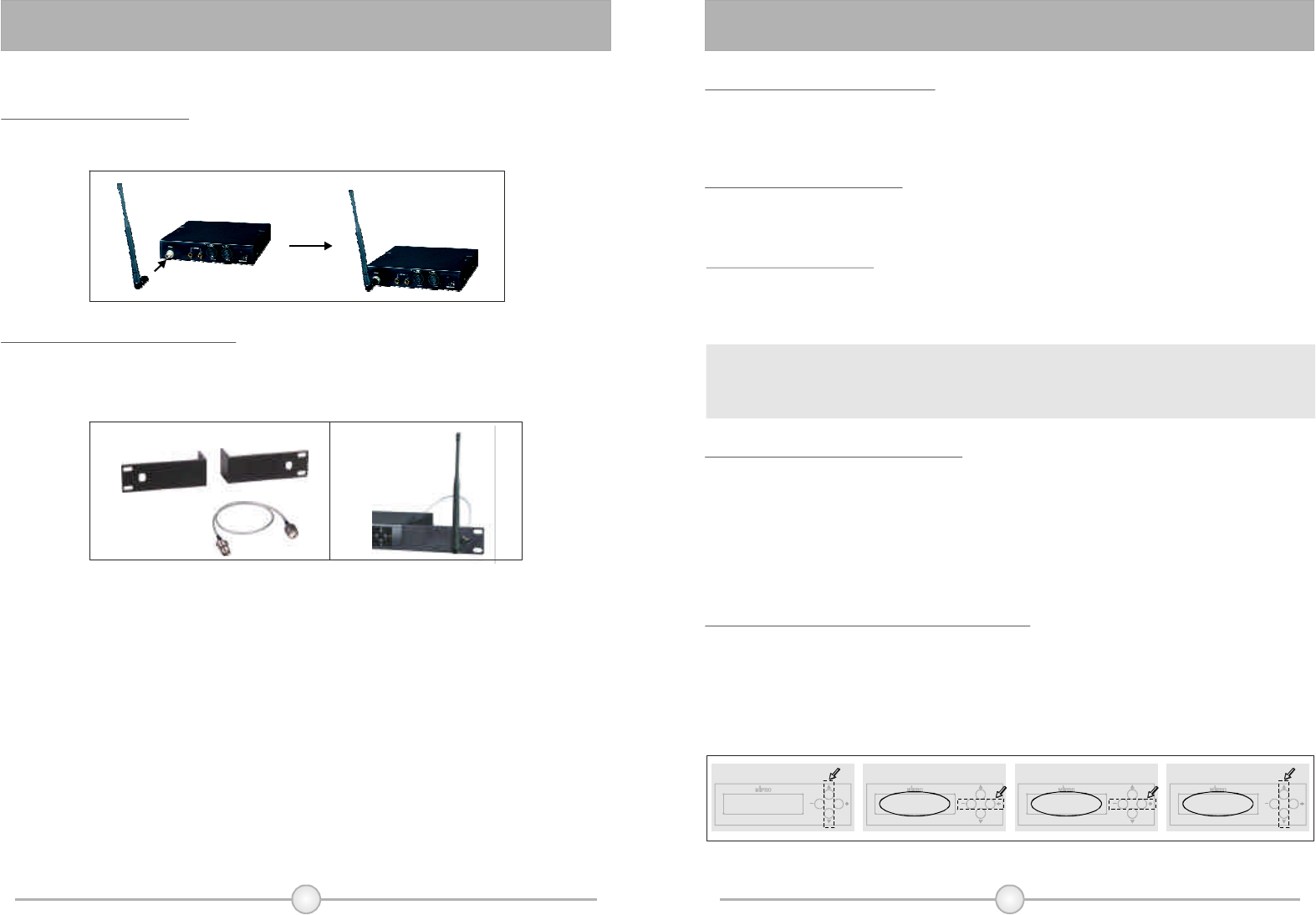
1.InstallationofAntenna
4.OperatingMI-808T:
45
Installcoaxialcableonthetransmitterwillreachthebesttransmissioneffectsbut
itmustnoticefrequencyconsistencyforbothantennaandtransmitter.
4.Turnonthetransmitter
Whenturnonthepowerswitch,thegreenLCDdisplaywillbebrightandshowall
informationonit.TransmitterwilloutputtransmissionsignalifPLLcircuitislocked.
5.Line-inLevelinput
ItcanselectstereoormonoLin-ininput,thesignalwillinputfromAFINofright
side.ItcanselectXLR-3balancedinputjackor6.3mmunbalancedinputjack.
Becauseofcompoundsocket,itisavailableforbothtypeofjacks.
φ
ConnectoutputendofDC12V~15V/1ApowersupplywithinputsocketofAC
poweroftransmitter.ToavoidthefalloffofDCplugaccidentally,gettingthrough
linkingcablefromfixholeandthenfastenit.
3.InstallationofPowerSupply
SelectFB-71Rackmountkit,useoneendtoconnectwithoutputsocketof
transmissionsignalandtheotherendconnectwithtransmissionantennas.The
transmissioneffectwillenhanceifinstallantennasinfrontofthepanel.
2.InstallationofFrontAntenna
6.SetupappropriateLINELEVEL
ThestrengthofLINELEVELinputwillshowontwobarofLINELEVELlistofleft
side.Adjustthestrengthofoutputappropriatelytolightupthreelamps.Themaximum
ofdisplayofLINELEVELwouldnotexceedfourlights.Wheninputstrengthexceeds
thestrengthoffourlights,theredlightwilllightup;andtheninputsignalshouldbe
limitedandmodulationshouldnotincrease.Therefore,adjustappropriateinput
strengthtoobtainthebestdynamicrangeandS/Nratioandavoidsignaldistrotion.
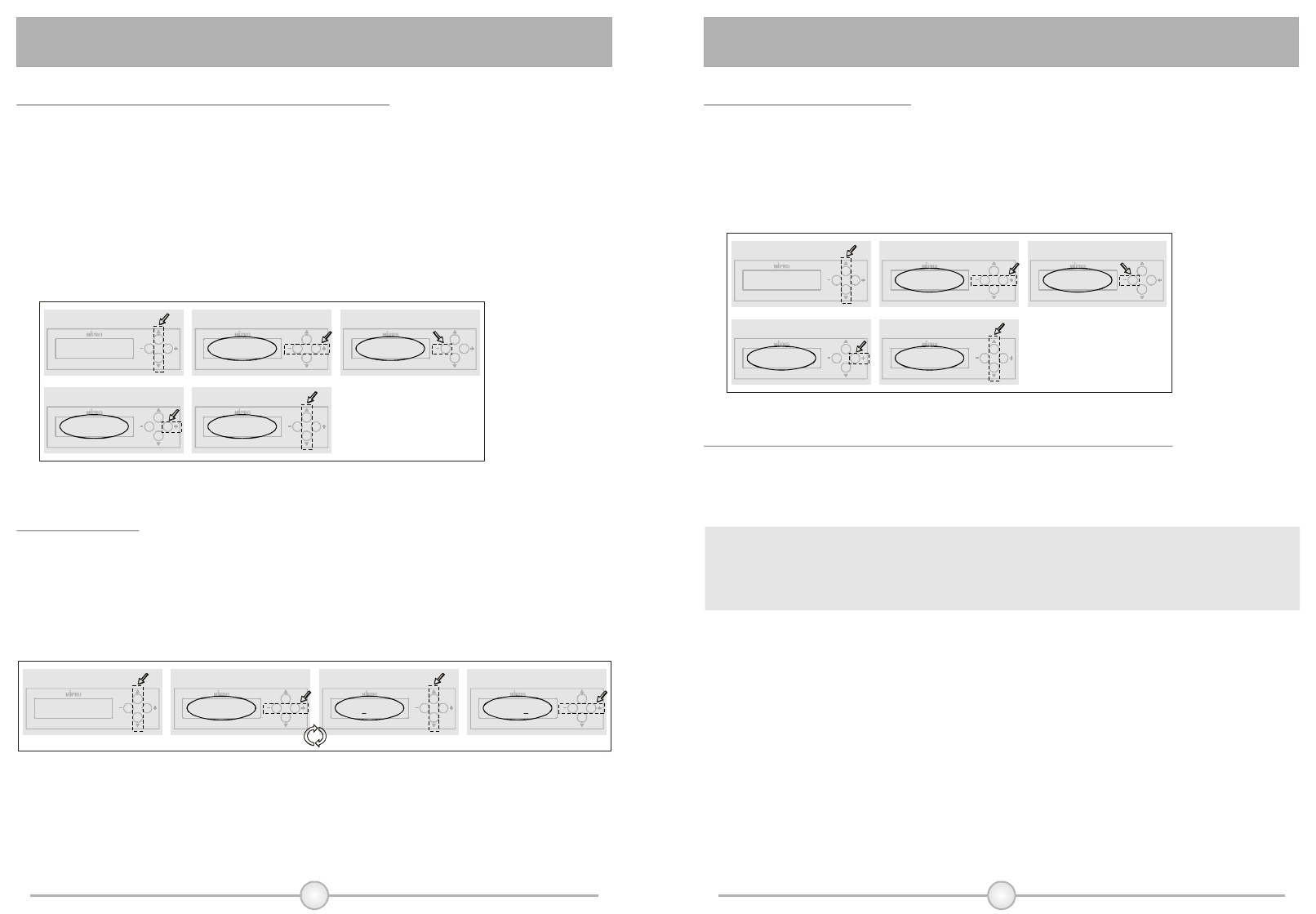
7.Howtosetuptransmissionfrequency:
a)Pressup/downkey,thenLCDdisplaywouldshowpresetfrequency.
b)Pressleft/rightkeyandthenLCDdisplaywillstartblinking.
c)Pressleft/rightkeytoselectdesiredfrequency.
d)Pressup/downkeytokeeptheLCDdisplayfixedandthentheselectedfrequency
isupdatedandsaved.
CH CH CH
FREQUENCY FREQUENCY FREQUENCY
0 0 0
4 5 5
5 0 0
MHz MHz MHz
2 8 82 0 0. . .1 4 48 8 81 1 1
MI-808TStereoTransmitter MI-808TStereoTransmitter MI-808TStereoTransmitter MI-808TStereoTransmitter
CH FREQUENCY
045
MHz
2 2.181
Displaystartsblinking ChangeFrequency SaveFrequencySelecttothedisplayoffrequency
a)
b)
c) d)
StereoTransmitter
StereoTransmitter
Cause:
ThestrengthlevelofsignalinputisLINELEVEL.Itmustmagnifythesignal
beforeinputifMICPHONELEVELinputisnecessary,otherwisesensitivityis
insufficient.Suggesttoconnectwithmonitoroutputjackofmixer.
Caution:
Toprotectyourhearing,adjustthevolueappropriately.Theoutputofheadphone
willoccurwhenvolumeistooloud.
Thesystemwillsaveandupdatecurrentsettingautomaticallyoncepressnoneof
thebottonin5secondswhenblinking.
10.SettingofLockFunction
a)Pressup/downkeytodisplayLockFunction.
b)Pressleftkey,displaywillshowLOCKON,allsettingislocked.Settingcan'tbe
changedbeforeremovingLockfunction.
c)Pressrightkey,displaywillshowLOCKOFF,Lockfunctionisremovableand
allowtochangeeachsetting.
11.HowtoMonitorSoundSignalandConnectwithHeadphone
PlugstereoheadphoneintoHeadphoneoutputsocket(2)andusevolumecontrol
toadjustthevolumeappropriately.Itmustadoptstereoconnectorof6.3mm.φ
MI-808TStereoTransmitter MI-808TStereoTransmitter MI-808TStereoTransmitter
STEREO STEREO STEREO
ON ON ONOFF OFF OFF
MONO MONO
SaveMode
e)
STEREO
ON OFF
MONO
MONO
Displaystartsblinking SelecttoStereoSoundSelecttoModeDisplay
a)
b)
c)
STEREO
ON OFF
MONO
SelectMonoSound
d)
LOCK LOCK LOCK
OFF OFF ON
SaveMode
e)
Displaystartsblinking LockFunctionSelecttoLockDisplay
a)
b)
c)
RemoveLockFunction
d)
6 7
8.TheoperatingtoselectStereoandMonosound
a)Pressup/downkeytodisplaySTEREO/MONOON/OFF.
b)Pressleft/rightkey,thenthedisplaystartblinking.
c)PressleftkeyandtheSTEREOwilldisplaythepositionofON.Itindicatesthe
selectingofStereotransmission.
d)PressrightkeyandMONOwilldisplaythepositionofON.Itindicatesthe
selectionofMonotransmission.
e)Pressupordownkeythenthedisplaystopsblinking.Atthisstage,theselecting
issaved.
9.SettingName
a)Pressup/downfunctionkeytodisplayNAMEonLCDdisplay.
b)Pressleft/rightfunctionkeythenthedisplaywillstartblinking.
c)Pressup/downfunctionkeytosetupalphabetornumerals.
d)Pressleft/rightfunctionkeytoskiptosettingofnextcharacter.Thenfinishthe
settingof6charactersbyduplicateoperation.
NAME NAME NAME NAME
ABCDEF ABCDEF -MCDEF -MIPRO
Thedisplayisblinking Changethename SelectnextcharacterSelecttothedisplayofNAME
a)
b)
b)
c)
c)
d)
LOCK LOCK
OFF OFF
MI-808TStereoTransmitter
MI-808TStereoTransmitter MI-808TStereoTransmitter MI-808TStereoTransmitter MI-808TStereoTransmitter
MI-808TStereoTransmitter
MI-808TStereoTransmitter
MI-808TStereoTransmitter MI-808TStereoTransmitter
MI-808TStereoTransmitter MI-808TStereoTransmitter
StereoTransmitter
StereoTransmitter
1.Don'tusesamefrequencybandforbothmonitorandwirelessmicrophone
systemwhentheyworksimultaneously.
2.Itmustuse50coaxialcabletoconnectthetransmissionsignalto
exteralantennas.Avoidtouselongcableexceeding5meterswhenuse
RG-58or3Dcables.
3.Itisbettertomaintainnon-barriersightdistancebetweentransmission
antennasandreceiver.Thisdistancewillshortenoncetherearetoo
manybarrierstoabsorbelectricwaveandobjects.
4.WhenusingDCpowersupply,pleasebeawareoftheoperatingvoltage.
Pleasemakesureminimumof12voltscanbeobtainedforfunction
properly.However,thepowersupplyshouldnotexceeditsmaximum
capacityof18volts.Whenthesupplyvoltageistoohigh,thesystemwill
suffersevereinternaldamange.Itispreferredthepowersourceisfrom
aregulatedpowerwiththeminimumcurrentof500mA.
Ω
8 9
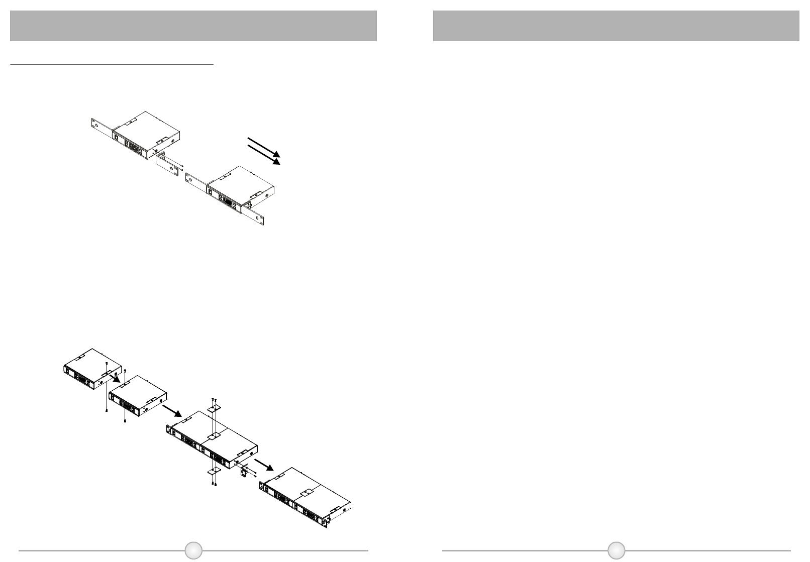
13.RackInstallationof2UnitsofMI-808T
A)Singlehalf-racktransmitter
(5)(fig.
①ScrewthefixedrackmountearonLeftandRightsides.Pleaseseebelow
illustrationforcorrectassembly.(Fig.5)
B)Dualhalf-racktransmitters
①
②
③
Removethescrewsoftopandbottomofthetwotransmitters
counterclockwise.
Positiontheconnectplatesbetweenthetopandbottomofthetwo
transmittersandtighten.
Afterjoiningthetwotransmitterstogether,screwtheoptionalaccessoryrack
mountears(FB-72)onleftandrightsides.(Fig.6)
(fig.6)
StereoTransmitter
StereoTransmitter
5.ImportantNotes:
Notice:
Thechangesormodificationsnotexpresslyapproved
bythepartyresponsibleforcompliancecouldvoidthe
user'sauthoritytooperatetheequipment.
IMPORTANTNOTE:
TocomplywiththeFCCRFexposurecompliance
requirements,nochangetotheantennaorthedeviceis
permitted.Anychangetotheantennaorthedevicecould
resultinthedeviceexceedingtheRFexposure
requirementsandvoiduser'sauthoritytooperatethe
device.

1110
NOTE﹕NOTE﹕