Mitec Telecom 217132-001MD Multi-carrier Power Amplifier User Manual 217132 001MA rev 3 FCC
Mitec Telecom Inc. Multi-carrier Power Amplifier 217132 001MA rev 3 FCC
Manual
mitec telecom inc.
Designers and manufacturers of telecom and wireless products
9000 Trans Canada,
Pointe-Claire, Quebec, Canada
H9R 5Z8
PRODUCT DOCUMENT
Preliminary Released
REVISION RECORD
Revision ECN # Description Date Approved
0
-
Preliminary release
03 Nov 09
P.Mousseau
1 Additional safety information regarding RF exposure.
07 Dec 09 P.Mousseau
More detailed description of the MCPA architecture.
2 Combo D-SUB MCPA connector pin out added 09 Dec 09 P.Mousseau
3 Restricted Area notification (section 2.2) 14 Dec 09 P.Mousseau
CM Approval
Author: P. Mousseau, ing. DATE: 03 NOV 09
Technical Writer: n/a DATE: 03 NOV 09
TITLE
24W Remote Node MCPA Installation
Instructions
REV. 3
This document contains information proprietary to mitec telecom inc., or its
affiliates, or to a third party to which mitec telecom inc. may have a legal obligation
to protect such information from unauthorized disclosure, use, or duplication. Any
disclosure, use, or duplication of this document or of any of the information
contained herein is expressly prohibited except as mitec telecom inc. may otherwise
agree in writing.
DOCUMENT NO.
217132-001MA
PAGE 1OF 18

REV. 3
This document contains information proprietary to mitec telecom inc., or its
affiliates, or to a third party to which mitec telecom inc. may have a legal obligation
to protect such information from unauthorized disclosure, use, or duplication. Any
disclosure, use,or duplication of this document or of any of the information
contained herein is expressly prohibited except as mitec telecom inc. may otherwise
agree in writing.
DOCUMENT NO.
217132-001MA PAGE 2

REV. 3
This document contains information proprietary to mitec telecom inc., or its
affiliates, or to a third party to which mitec telecom inc. may have a legal obligation
to protect such information from unauthorized disclosure, use, or duplication. Any
disclosure, use,or duplication of this document or of any of the information
contained herein is expressly prohibited except as mitec telecom inc. may otherwise
agree in writing.
DOCUMENT NO.
217132-001MA PAGE 3
Table of Contents
1.0
SCOPE ......................................................................................................................................................................... 4
2.0
SYSTEM OVERVIEW .................................................................................................................................................. 5
2.1
GENERAL DESCRIPTION ..............................................................................................................................................................5
2.1.1
Abbreviations and Explanations.........................................................................................................................................5
2.2
PREPARING FOR INSTALLATION ..................................................................................................................................................5
2.3
SAFETY PRECAUTIONS ................................................................................................................................................................ 6
2.4
WARRANTY INFORMATION .........................................................................................................................................................6
2.4.1
Equipment Damage or Loss ...............................................................................................................................................7
2.4.2
Return of Equipment.......................................................................................................................................................... 7
3.0
SYSTEM INSTALLATION .......................................................................................................................................... 8
3.1
SYSTEM BLOCK DIAGRAM.......................................................................................................................................................... 8
3.2
INSTALLATION OVERVIEW..........................................................................................................................................................9
3.2.1
24W Remote Node MCPA Installation............................................................................................................................11
3.2.1.1 24W Remote Node MCPA Pole Mounting
..................................................................................................................11
3.2.1.2 Optional 24W Remote Node MCPA Flat Wall Surface Mounting
.......................................................................13
4.0
SYSTEM VERIFICATION TEST................................................................................................................................ 15
APPENDIX A
MCPA CONNECTOR PIN OUT............................................................................................................... 17
APPENDIX B
FAN CONTROLLER BOARD J3 CONNECTOR PIN OUT ....................................................................18
List of Figures
Figure 1 – System Block Diagram.............................................................................................................................................................8
Figure 2 – 20W MCPA Remote Node Block Diagram..............................................................................................................................8
Figure 3 – Wall mount or pole mount installation .....................................................................................................................................9
Figure 4 – Required Hardware................................................................................................................................................................... 9
Figure 5 – Recommended Test Setup ...................................................................................................................................................... 15
Figure 6 – System Verification Flow Chart .............................................................................................................................................16
List of Tables
Table 1 - Abbreviations Table ................................................................................................................................................................... 5

REV. 3
This document contains information proprietary to mitec telecom inc., or its
affiliates, or to a third party to which mitec telecom inc. may have a legal obligation
to protect such information from unauthorized disclosure, use, or duplication. Any
disclosure, use,or duplication of this document or of any of the information
contained herein is expressly prohibited except as mitec telecom inc. may otherwise
agree in writing.
DOCUMENT NO.
217132-001MA PAGE 4
1.0 Scope
This package includes documentation for mitec’s 24W Remote Node MCPA. It is intended to provide
customer personnel with a comprehensive reference manual for installation and operation.
The package is structured as follows;
2.0 System Overview
2.1 General Description
2.2 Preparing for Installation
2.3 Safety Precautions
2.4 Warranty Information
3.0 System Installation
This section contains information for the connection of the various components of the 24W Remote
Node MCPA, including system connections.
4.0 System Operation Test
This section describes the test to be carried out after installation to ensure proper operation.
REV. 3
This document contains information proprietary to mitec telecom inc., or its
affiliates, or to a third party to which mitec telecom inc. may have a legal obligation
to protect such information from unauthorized disclosure, use, or duplication. Any
disclosure, use,or duplication of this document or of any of the information
contained herein is expressly prohibited except as mitec telecom inc. may otherwise
agree in writing.
DOCUMENT NO.
217132-001MA PAGE 5
2.0 System Overview
2.1 General Description
The 24W Remote Node MCPA is composed of an MCPA (Multi-Carrier Power Amplifier), a passive TX
Filter, an AC Power Supply, two fans and a DCDC Converter board. It’s main feature is to amplify one
or more RF carriers in a range of 27.5 to 43.0dB.
Modules Description
The Power Supply converts the 110VAC to +28VDC to power up the MCPA and the DCDC Converter
module.
The DCDC Converter module provides +24VDC to the fans and a +5VDC for the Controller module (not
included in the Remote Node MCPA as shipped to the customer).
The MCPA’s function is to amplify the input signal by 48dB. The MCPA is a linearized feed-forward
amplifier with a pilot tone. There are two sections to the amplifier, the main amplifier and the error
amplifier. The error amplifier is there to cancel part of the intermodulation products that are generated
in the main amplifier whose function is to amplify the input signal to 24Watts. The pilot tone is used to
monitor and cancel these intermodulation products. The cancellation is adaptive, meaning that a
sample of the pilot tone is fed back to the main and error amplifier to adjust their phase and amplitude
to maintain good cancellation of the intermodulation products over time and temperature.
The MCPA gain is controlled using an integrated digital attenuator, which has a range of 0 to 15.5dB.
The MCPA also has over power and over temperature protection.
The TX Band Pass Filter is used to remove undesired the out of band spurious.
2.1.1 Abbreviations and Explanations
Table 1 - Abbreviations Table
Abbreviation Explanation
BTS Base Transceiver Station
DAS Distributed Antenna System
MCPA Multi-Carrier Power Amplifier
MHz Megahertz
mm millimeter
RN Remote Node
2.2 Preparing for Installation
Before attempting to install or use the 24W Remote Node MCPA, we recommend that you first
familiarize yourself by reading through this documentation package. Understanding the system
operation will reduce the possibility of incorrect installation, thereby causing damage or injury to
yourself or others.
The MCPA must be installed in accordance with the conditions and recommendations
contained in the following sections. The HPA must be installed in a restricted
location area accessible only to authorized personnel.

REV. 3
This document contains information proprietary to mitec telecom inc., or its
affiliates, or to a third party to which mitec telecom inc. may have a legal obligation
to protect such information from unauthorized disclosure, use, or duplication. Any
disclosure, use,or duplication of this document or of any of the information
contained herein is expressly prohibited except as mitec telecom inc. may otherwise
agree in writing.
DOCUMENT NO.
217132-001MA PAGE 6
2.3 Safety Precautions
Carelessness or mishandling of the 24W Remote Node MCPA may damage the equipment causing
serious injury to yourself or others. All installation activity must be carried out in compliance with the
safety instructions supplied with the BTS and with local standard authority warnings and precautions..
Please adhere to the following:
WARNING!!
This equipment is designed for use with high power radio frequency (RF) radiating
systems. Personnel must take precautions to minimize exposure to the RF fields by
making sure that the output port is terminated(connected to an antenna OR attached to a
>40W RF load) at all time when the amplifier is running. It is also highly recommended
that the input port is terminated to protect the devices from accidental overdrive
(oscillations), which could damage the amplifier.
WARNING!!
The equipment is designed for use with equipment that generates high voltages.
Proper precautions must be taken when working with this equipment.
CAUTION!
To prevent damage to static sensitive devices, ESD (electrostatic discharge)
precautions must be observed when handling or installing the modules or
subassemblies of the 24W Remote Node MCPA.
Do not tamper with, or attempt to reconfigure, the cords or plugs supplied with
the modules of the 24W Remote Node MCPA, as this can:
♦ result in personal injury
♦ void the warranty
♦ cause damage to the units or related equipment
2.4 Warranty Information
Mitec Telecom Inc. will warranty each product that it manufactures to be free from defects in materials
and workmanship for a period of twelve (12) months.
Mitec’s only obligation under this warranty is to, at its option, repair or replace any product or part
thereof that is returned with transportation charges prepaid to Mitec Telecom Inc. by the original
purchaser within one year after delivery to the original purchaser, and which, upon examination by
Mitec, is determined to be defective or to have failed the normal service.

REV. 3
This document contains information proprietary to mitec telecom inc., or its
affiliates, or to a third party to which mitec telecom inc. may have a legal obligation
to protect such information from unauthorized disclosure, use, or duplication. Any
disclosure, use,or duplication of this document or of any of the information
contained herein is expressly prohibited except as mitec telecom inc. may otherwise
agree in writing.
DOCUMENT NO.
217132-001MA PAGE 7
2.4.1 Equipment Damage or Loss
Mitec Telecom Inc. is not responsible for damage or loss of equipment during transit. For further
information, contact the responsible transport carrier.
When declaring equipment as damaged during transit, preserve the original shipping cartons to
facilitate inspection reporting.
2.4.2 Return of Equipment
All warranty returns must be authorized by the Mitec Customer Service Department, which will issue
a Return Material Authorization (RMA) number. This is important for prompt, efficient handling of the
returned equipment and of the associated complaint
When returning equipment to Mitec for repair or replacement:
1. Notify Mitec Customer Service Department of the equipment condition and obtain a Return
Material Authorization (RMA) number and shipping instructions at:
a. Email: sales@mitectelecom.com
b. Telephone: (514)694-9000 ext. 2122
c. Fax: (514)694-3814
2. Identify, in writing, the condition of the equipment.
3. Include to the Part Number, Serial Number, Sales Order, Purchase Order and the date the
equipment was received.
4. Mitec will pay for the cost of shipping the product to the customer after the repairs are
completed.
REV. 3
This document contains information proprietary to mitec telecom inc., or its
affiliates, or to a third party to which mitec telecom inc. may have a legal obligation
to protect such information from unauthorized disclosure, use, or duplication. Any
disclosure, use,or duplication of this document or of any of the information
contained herein is expressly prohibited except as mitec telecom inc. may otherwise
agree in writing.
DOCUMENT NO.
217132-001MA PAGE 8
3.0 System Installation
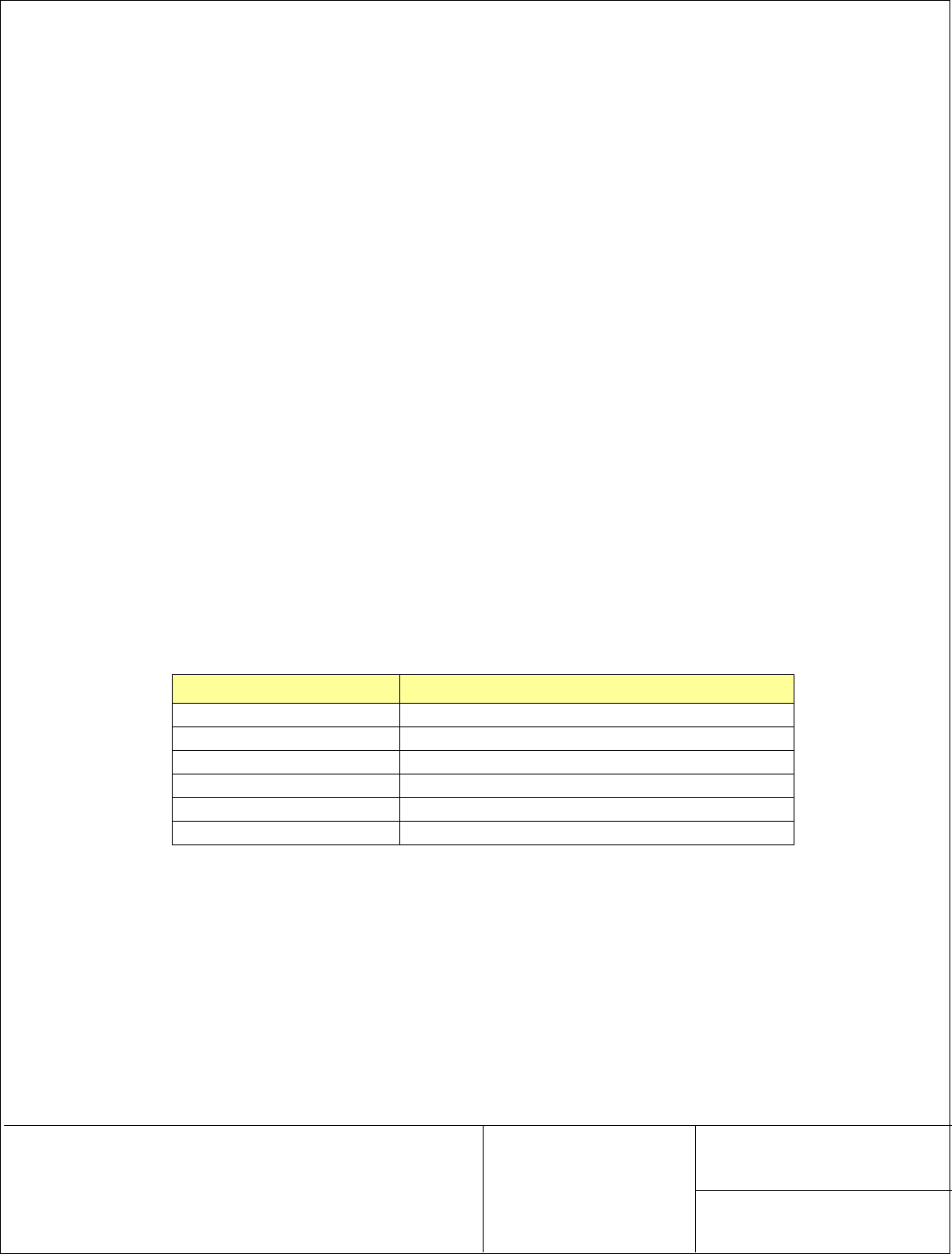
3.1 System Block Diagram
Site 110VAC
Supply
BTS Equipment 20W MCPA Uni-Directional Remote Node
RF In
Antenna
RJ45
M&C System
(PC)
Figure 1 – System Block Diagram
Customer Controller
(not included)
DCDC
Converter
Power Supply
IL= 0.8 dB
F
C
= 860 MHz
Ref = BPF1
BW= 18 MHz
AC
Input
RF
Input 7/16
RJ-45
RF
Output
Optical
Fan
Fan
Gain = 48 +/-1dB
Digital Input Attenuator = 0-15.5dB
Figure 2 – 20W MCPA Remote Node Block Diagram
REV. 3
This document contains information proprietary to mitec telecom inc., or its
affiliates, or to a third party to which mitec telecom inc. may have a legal obligation
to protect such information from unauthorized disclosure, use, or duplication. Any
disclosure, use,or duplication of this document or of any of the information
contained herein is expressly prohibited except as mitec telecom inc. may otherwise
agree in writing.
DOCUMENT NO.
217132-001MA PAGE 9
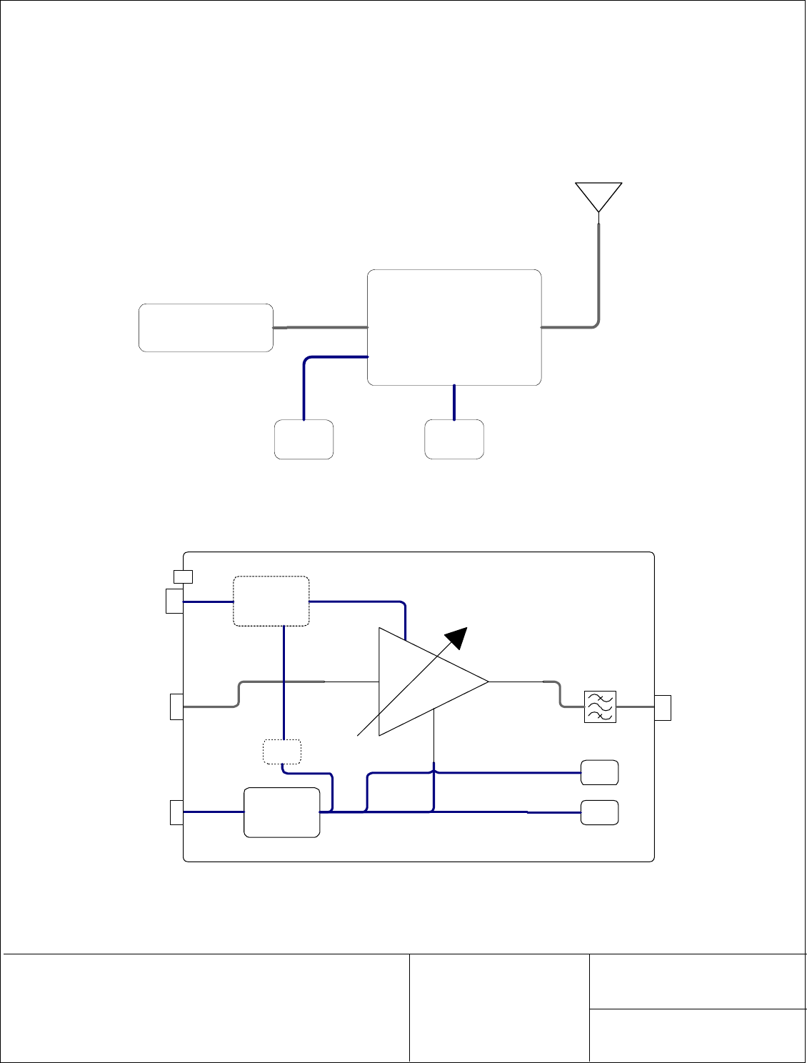
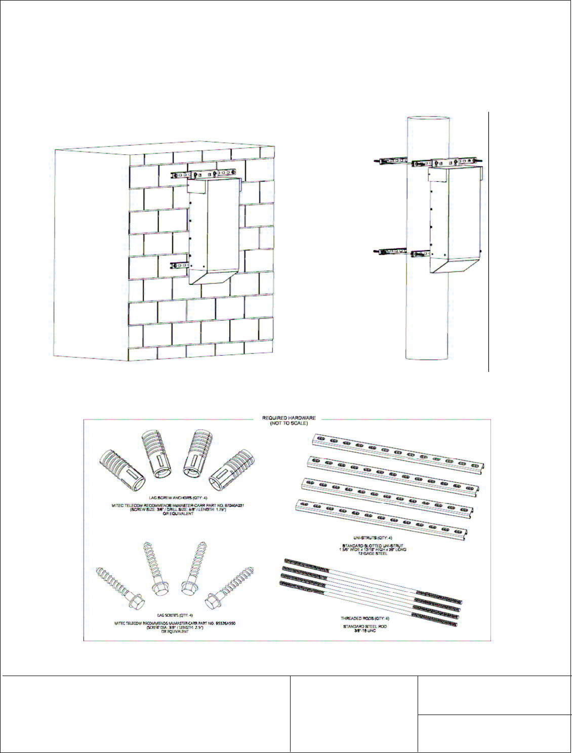
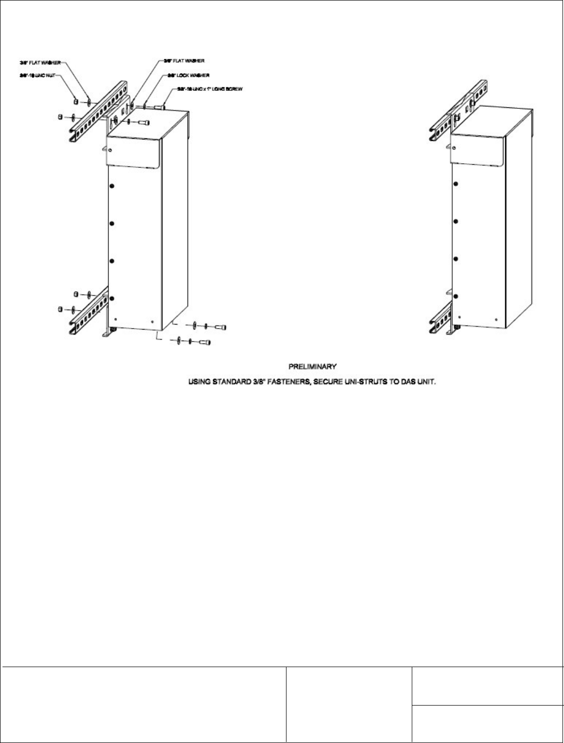
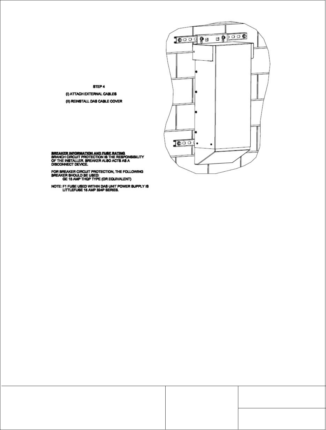
3.2 Installation Overview
The following section describes how to mount the 24W Remote Node MCPA. It can be wall mount or
on a pole. Both methods are detailed below.
Figure 3 – Wall mount or pole mount installation
Figure 4 – Required Hardware
REV. 3
This document contains information proprietary to mitec telecom inc., or its
affiliates, or to a third party to which mitec telecom inc. may have a legal obligation
to protect such information from unauthorized disclosure, use, or duplication. Any
disclosure, use,or duplication of this document or of any of the information
contained herein is expressly prohibited except as mitec telecom inc. may otherwise
agree in writing.
DOCUMENT NO.
217132-001MA PAGE 10
REV. 3
This document contains information proprietary to mitec telecom inc., or its
affiliates, or to a third party to which mitec telecom inc. may have a legal obligation
to protect such information from unauthorized disclosure, use, or duplication. Any
disclosure, use,or duplication of this document or of any of the information
contained herein is expressly prohibited except as mitec telecom inc. may otherwise
agree in writing.
DOCUMENT NO.
217132-001MA PAGE 11
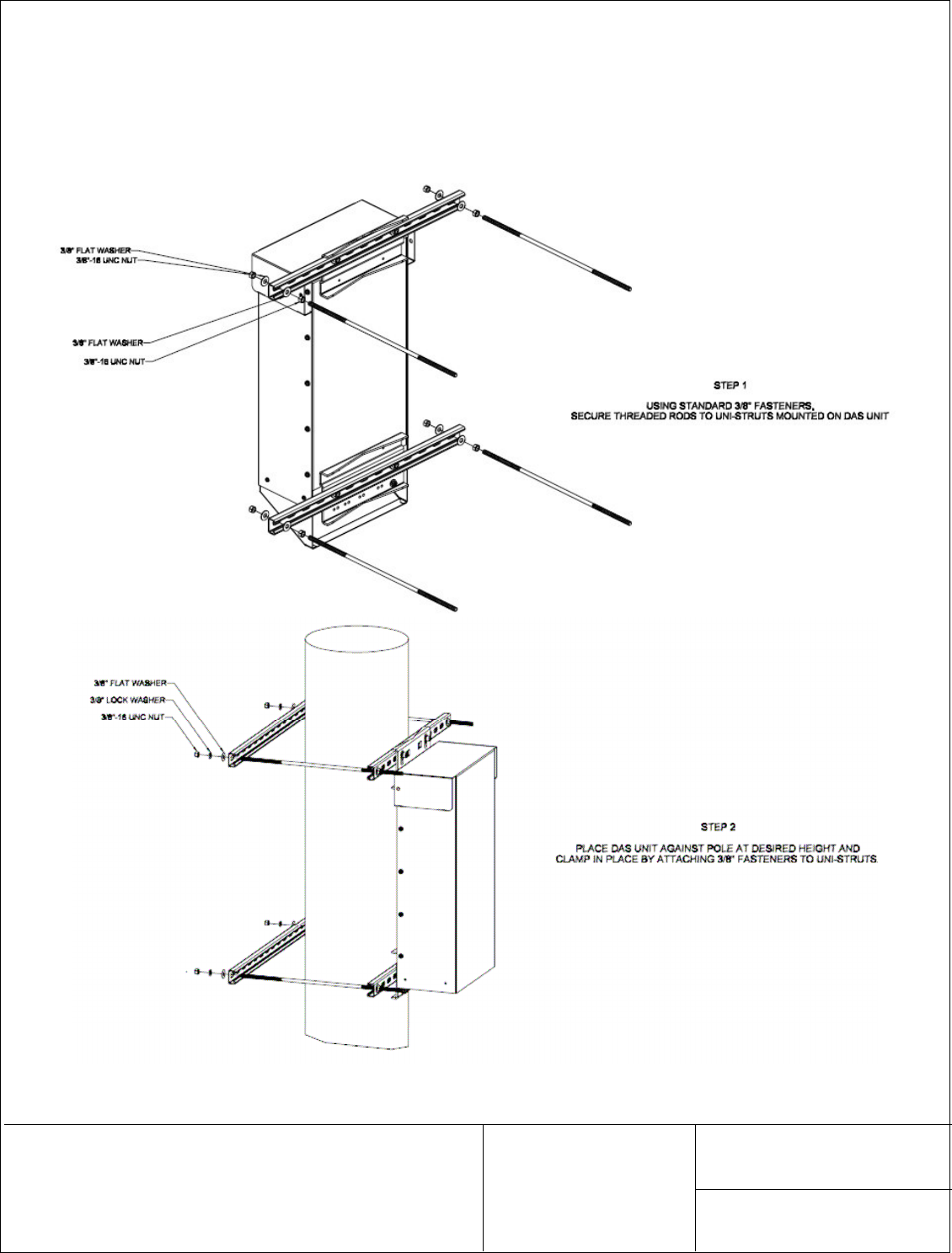
3.2.1 24W Remote Node MCPA Installation
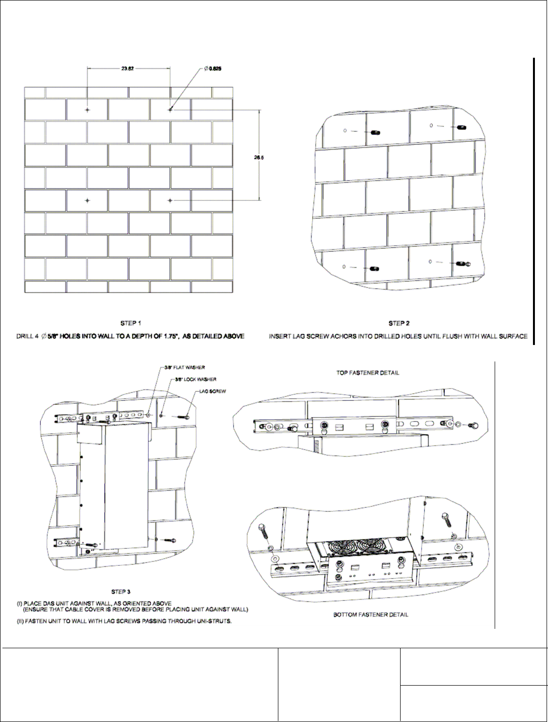
The 24W Remote Node MCPA has been designed to be mounted on a flat wall surface or on a pole as
close as possible to the associated antenna.
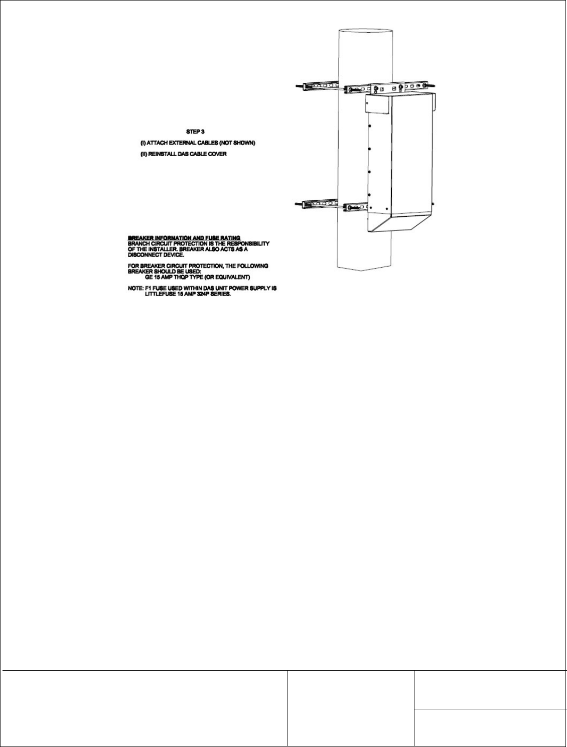
3.2.1.1 24W Remote Node MCPA Pole Mounting
REV. 3
This document contains information proprietary to mitec telecom inc., or its
affiliates, or to a third party to which mitec telecom inc. may have a legal obligation
to protect such information from unauthorized disclosure, use, or duplication. Any
disclosure, use,or duplication of this document or of any of the information
contained herein is expressly prohibited except as mitec telecom inc. may otherwise
agree in writing.
DOCUMENT NO.
217132-001MA PAGE 12
REV. 3
This document contains information proprietary to mitec telecom inc., or its
affiliates, or to a third party to which mitec telecom inc. may have a legal obligation
to protect such information from unauthorized disclosure, use, or duplication. Any
disclosure, use,or duplication of this document or of any of the information
contained herein is expressly prohibited except as mitec telecom inc. may otherwise
agree in writing.
DOCUMENT NO.
217132-001MA PAGE 13
3.2.1.2 Optional 24W Remote Node MCPA Flat Wall Surface Mounting
REV. 3
This document contains information proprietary to mitec telecom inc., or its
affiliates, or to a third party to which mitec telecom inc. may have a legal obligation
to protect such information from unauthorized disclosure, use, or duplication. Any
disclosure, use,or duplication of this document or of any of the information
contained herein is expressly prohibited except as mitec telecom inc. may otherwise
agree in writing.
DOCUMENT NO.
217132-001MA PAGE 14
REV. 3
This document contains information proprietary to mitec telecom inc., or its
affiliates, or to a third party to which mitec telecom inc. may have a legal obligation
to protect such information from unauthorized disclosure, use, or duplication. Any
disclosure, use,or duplication of this document or of any of the information
contained herein is expressly prohibited except as mitec telecom inc. may otherwise
agree in writing.
DOCUMENT NO.
217132-001MA PAGE 15
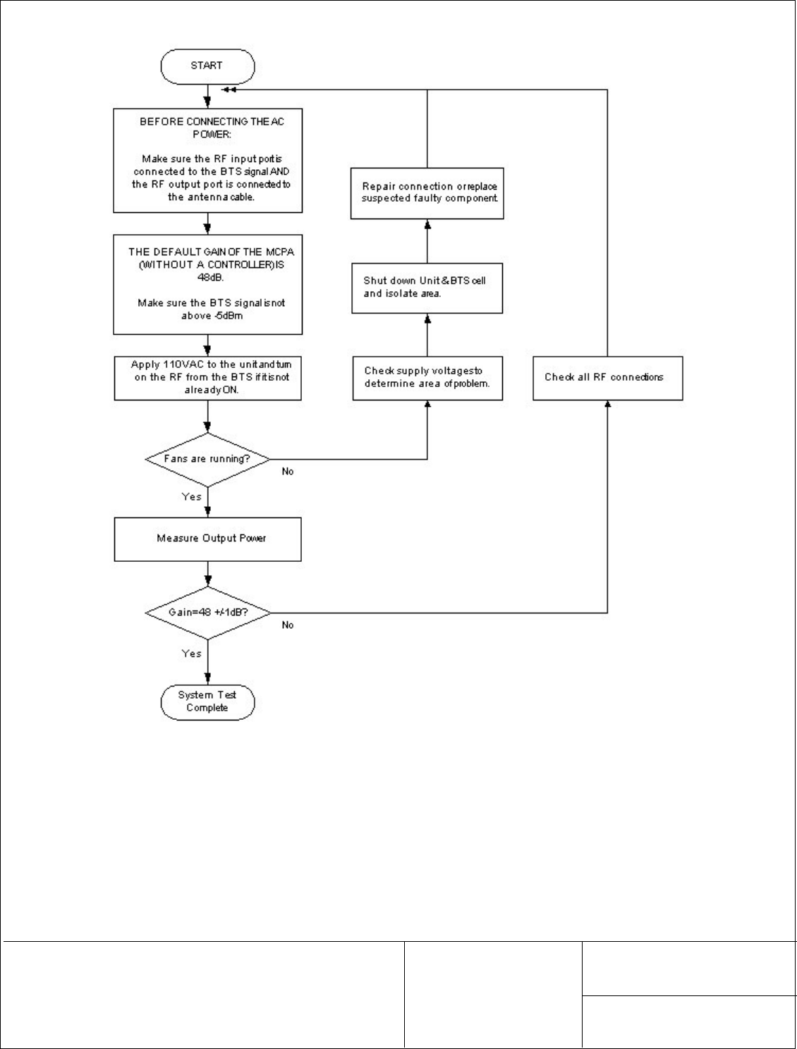
4.0 System Verification Test
The following test sequence should be carried out to make a quick functional test or verification of the
unit. It is not intended to cover all system capabilities, but rather to confirm that the MCPA is ‘healthy’
and can deliver the expected RF power.
WARNING!!
The equipment is shipped without a controller (provided and integrated by the
customer). In order to test the unit, a “ jumper” has been soldered to short pin 1
and 15 of the MCPA DSUB 15 connector to enable the MCPA at power up.
Operator must make sure to connect the RF Output port to an Antenna or a 50W RF
Load before applying AC Power to the unit.
Operator must make sure the RF input port is not left opened to avoid oscillation.
The RF input cable (from the BTS) must be connected or the port terminated with a
50-Ohm adapter.
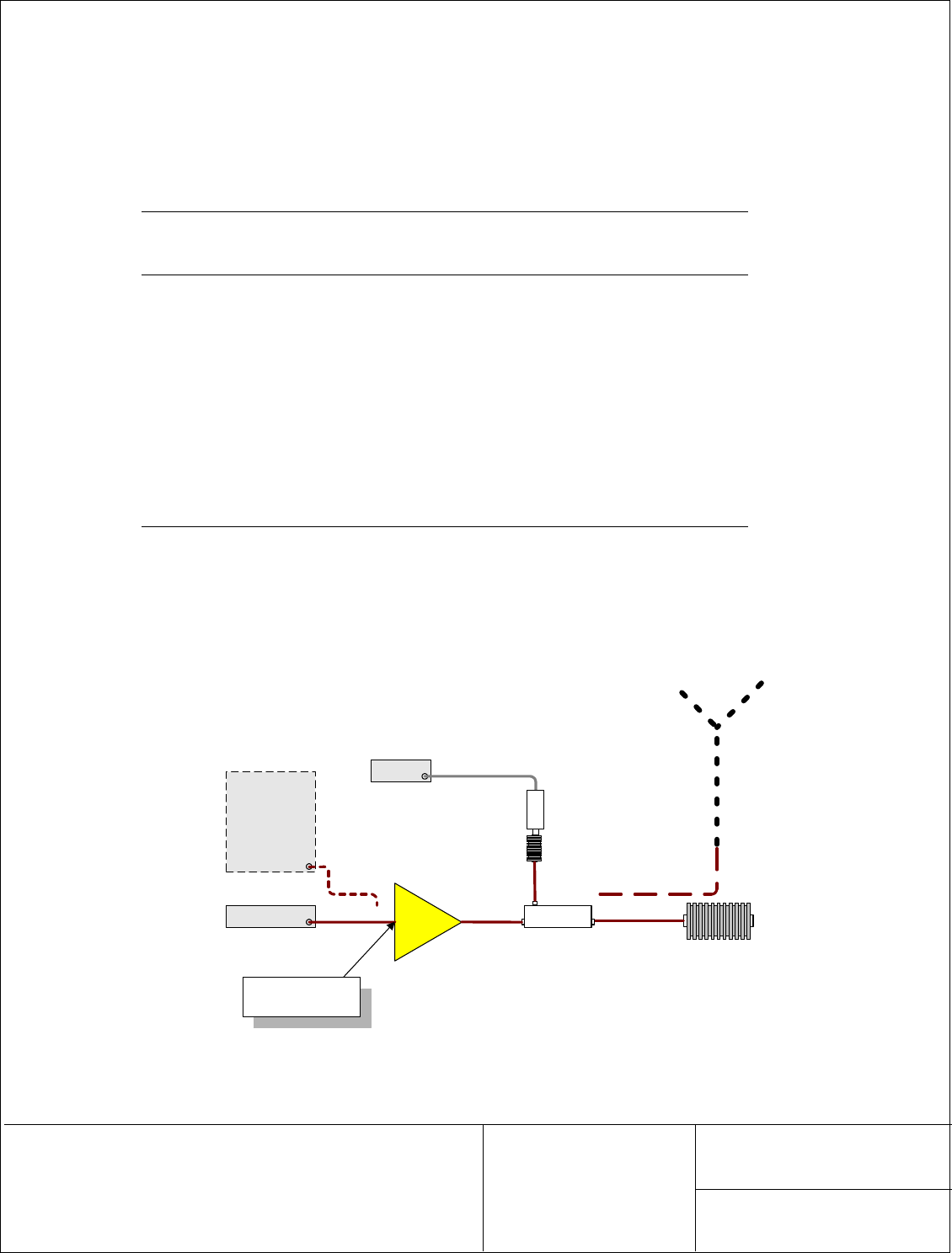
The following picture shows the recommended bench setup for the verification. The Signal Generator
could be replaced by the BTS signal and the RF Load by the antenna and its cable. The output power
could be measured by reading the dc voltage on pin 9 of the MCPA DSUB connector, but the
recommended setup was defined such a way to avoid opening the unit. For that reason an external
coupler is required.
PWM
SigGen 20W
MCPA
Coupler
20dB
> 30W load
20dB pad
Power Head
Max Input: -3dBm
BTS
OR
OR
Figure 5 – Recommended Test Setup
REV. 3
This document contains information proprietary to mitec telecom inc., or its
affiliates, or to a third party to which mitec telecom inc. may have a legal obligation
to protect such information from unauthorized disclosure, use, or duplication. Any
disclosure, use,or duplication of this document or of any of the information
contained herein is expressly prohibited except as mitec telecom inc. may otherwise
agree in writing.
DOCUMENT NO.
217132-001MA PAGE 16
Figure 6 – System Verification Flow Chart
REV. 3
This document contains information proprietary to mitec telecom inc., or its
affiliates, or to a third party to which mitec telecom inc. may have a legal obligation
to protect such information from unauthorized disclosure, use, or duplication. Any
disclosure, use,or duplication of this document or of any of the information
contained herein is expressly prohibited except as mitec telecom inc. may otherwise
agree in writing.
DOCUMENT NO.
217132-001MA PAGE 17
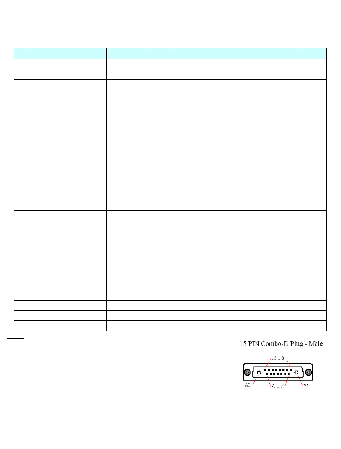
Appendix A MCPA Connector pin out
Pin
Name Type Active Details Notes
A1 +30 Vdc ground Analog -
A2 +30 Vdc supply Analog -
1
/
RF Power Enable Digital Input LOW Pulled LOW: PA is turned ON
Pulled HIGH: PA is turned OFF
Tri-state: PA is turned OFF
2
/
RF Enabled Digital Output LOW
Driven HIGH and PA is turned OFF if:
• Pin 1 is Tri-state or pulled HIGH or
• Temperature exceeds safe operating limit or
• Current exceeds max current rating or
• PA is protecting itself from damage or
• PA has been Shut Down or
• PA has otherwise failed
2
3 Over Temperature Digital Output HIGH Set HIGH if PA has exceeded safe operating
temperature 3
4 VSWR Alarm Digital Output HIGH Set HIGH of VSWR > 3:1 4
5 Low Gain Alarm Digital Output HIGH Set HIGH if PA gain < 6 dB of the set gain 4
6 Over Drive & Shut Down Digital Output HIGH Set HIGH if Pin > 6 dBm & Shut Down 3
7 Over Power & Shut Down Digital Output HIGH Set HIGH if Pout > 46 dBm & Shut Down 3
8 Baseplate Temp Sense Analog
Output - Vout = (10mV / °C) x (Temp °C) + 500mV 1
9 Forward RF Power Detector Analog
Output - Linear Analog Output with limits:
0.0V @ +25 dBm
2.5V @ +45 dBm
10 0.5 dB Atten Digital Input LOW Attenuates gain by 0.5 dB 2
11 1.0 dB Atten Digital Input LOW Attenuates gain by 1.0 dB 2
12 2.0 dB Atten Digital Input LOW Attenuates gain by 2.0 dB 2
13 4.0 dB Atten Digital Input LOW Attenuates gain by 4.0 dB 2
14 8.0 dB Atten Digital Input LOW Attenuates gain by 8.0 dB 2
15 Signal Ground -
Notes:
1. Recommended device: National LM50 (or equivalent)
2. Must have at least 5.0k pull-up resistor to +3.3V
3. These alarms will turn off the PA. Once the alarm condition has been removed the
PA will clear the alarm and resume normal operation
4. These alarms will not cease operation of the PA. Once the alarm condition has
been removed the alarm will clear itself
REV. 3
This document contains information proprietary to mitec telecom inc., or its
affiliates, or to a third party to which mitec telecom inc. may have a legal obligation
to protect such information from unauthorized disclosure, use, or duplication. Any
disclosure, use,or duplication of this document or of any of the information
contained herein is expressly prohibited except as mitec telecom inc. may otherwise
agree in writing.
DOCUMENT NO.
217132-001MA PAGE 18
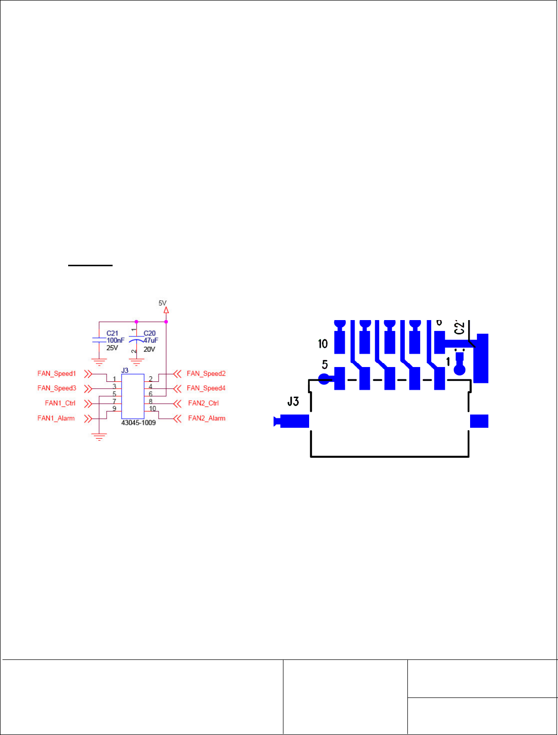
Appendix B Fan Controller Board J3 connector pin out
The following information describes connector J3 on the Fan Controller board and its footprint has been
added to clarify the exact pin out of the connector.
Fan[1 or 2]_Ctrl -> 1 to turn off the fan [1 or 2]
Fan_Speed1 -> 1 to slow down fans speed
Fan_Speed2 -> 1 to slow down fans speed
Fan_Speed3 -> 1 to slow down fans speed
Fan_Speed4 -> 1 to slow down fans speed
*** Only one fan_Speedx signal must be used at a time.