MitraStar Technology M4G3401 M4G-3401 LTE Outdoor CPE User Manual Quick Start Guide
MitraStar Technology Corporation M4G-3401 LTE Outdoor CPE Quick Start Guide
UserManual.wiki
>
MitraStar Technology
>
M4G3401 User Manual
User Manual
Navigation menu
Upload a User Manual
Namespaces
Wiki Guide
HTML
PDF
Info
Views
User Manual
Discussion / Help
Navigation
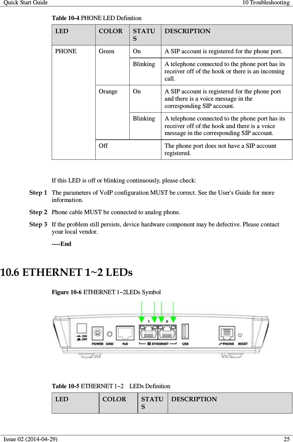
![Quick Start Guide 10 Troubleshooting Issue 02 (2014-04-29) 26 LED COLOR STATUS DESCRIPTION ETHERNET 1-2 Yellow (Giga Ethernet) On The LTE Device has a successful 1000 Mbps Ethernet connection with a device on the Local Area Network (LAN). Blinking The LTE Device is sending or receiving data to/from the LAN at 1000 Mbps. Green (Fast Ethernet) On The LTE Device has a successful 10/100 Mbps Ethernet connection with a device on the Local Area Network (LAN). Blinking The LTE Device is sending or receiving data to/from the LAN at 10/100 Mbps. Off The LTE Device does not have an Ethernet connection with the LAN. If the LED is off, please check: Step 1 The LAN cable MUST be connected between device and PC. Step 2 NIC function on the PC MUST be enabled. Step 3 If the problem still persists, device hardware component may be defective. Please contact your local vendor. ----End I cannot access the IDU from my LAN: Check the cable connection between the LTE Device and your computer or switch and ensure that both ends are secure. Make sure your computer has gotten an IP address (default is 192.168.1.x) in the same network as the LTE Device's LAN. If not, you can manually configure your computer by clicking Start > Control Panel > Network Connections > Local Area Connection > Properties > Internet Protocol (TCP/IP). Ping the LTE Device from a LAN computer: Click Start > (All) Programs > Accessories > Command Prompt. When the command prompt window opens, type "ping 192.168.1.1" without quotes and press [ENTER]. The LTE Device should reply. Press and hold the RESET button for about 10 seconds to reset the device to its default factory settings, then try to connect to the IP 192.168.1.1 once more. I cannot log into the Web Configurator: Check to see if anyone else is currently logged into the LTE Device. If so, you may not be able to log in until they log out first. If you've forgotten the LTE Device's user name, password, or IP address press and hold the Reset button for about 10 seconds. The LTE Device returns to the factory default settings listed on the first page of this book.](https://usermanual.wiki/MitraStar-Technology/M4G3401/User-Guide-2510453-Page-28.png)