Mitsubishi Electronics Cp700E Users Manual Cover
CP700E mitsubishi_cp700e_manual
CP700E to the manual 75ab086a-a61e-4c03-8bfe-4b0057de173a
2015-02-09
: Mitsubishi-Electronics Mitsubishi-Electronics-Cp700E-Users-Manual-557166 mitsubishi-electronics-cp700e-users-manual-557166 mitsubishi-electronics pdf
Open the PDF directly: View PDF ![]() .
.
Page Count: 91

COLOUR VIDEO COPY PROCESSOR
MODEL
CP700E
OPERATION MANUAL
THIS OPERATION MANUAL IS IMPORTANT
TO YOU.
PLEASE READ IT BEFORE USING YOUR
COLOUR VIDEO COPY PROCESSOR.
POWER
OPEN
REMOTE
MEMORY PRINT
MONITOR
CP700
This video copy processor complies with the requirements of the EC
Directive 89/336/EEC, 73/23/EEC, 93/42/EEC and 93/68/EEC.
The electro-magnetic susceptibility has been chosen at a level that
gains proper operation in residential areas, on business and light
industrial premises and on small-scale enterprises, inside as well as
outside of the buildings. All places of operation are characterised by
their connection to the public low voltage power supply system.

1
1. Contents................................................................................................................. 1
2. Precautions .........................................................................................................2-4
3. Preparations before operation .......................................................................... 5-13
4. Connection with external equipment............................................................... 14-21
5. Features and functions ................................................................................... 22-26
6. Printing procedures
Basic prints................................................................................................. 27-36
7. Setting the functions
Menu display chart ..................................................................................... 38-41
Main menu ................................................................................................. 42-53
Making a comment ..................................................................................... 53-58
Memory switch menu ................................................................................. 59-64
8. Printing procedures
Special prints.............................................................................................. 65-83
9. Troubleshooting
Error messages and countermeasures ...................................................... 84-85
Overcoming paper jams .................................................................................. 85
Before calling for service ............................................................................ 86-87
10. Options ( Sold separately ) ................................................................................ 88
11. Specifications..................................................................................................... 89
1. Contents
11
11
1 Contents
11
11
1 Accessories
0 Operation manual ( 2 )
0 Power cord ( 1 )
0 Lithium battery (CR2025 ) ( 1 )
0 Remote control ( 1 )
0 Spacer ( 4 )
0 Additional sheet
• Installing print paper and ink sheet
0 Ink-cassette ( 1 )

2
In the interest of safety, please observe the following precautions:
POWER REQUIREMENT
This Colour Video Copy Processor is designed for operation on 220-240V, 50Hz AC. Never connect to any outlet or power supply having a
different voltage or frequency.
WARNING: THIS APPARATUS MUST BE EARTHED.
AVERTISSEMENT: CET APPAREIL DOIT ETRE MIS A LA TERRE.
PROTECTIVE MEASURES
IF ABNORMALITIES ARISE, .....
Use of the unit during emission of smoke or abnormal sounds (without adopting countermeasures) is dangerous. In such a case, unplug the
power cord from the source outlet immediately, and request maintenance service from the sales dealer.
NEVER INSERT ANY OBJECT INTO THE UNIT
Foreign objects of any kind inserted into this unit constitute a safety hazard and can cause extensive damage.
DO NOT PLACE ANYTHING ON THE COLOUR VIDEO COPY PROCESSOR
Heavy objects placed on the Colour Video Copy Processor can cause damage or obstruct proper ventilation.
PROTECT THE POWER CORD
Damage to the power cord may cause fire or shock hazard. When unplugging, hold by the plug only and remove carefully.
DO NOT PLACE WATER CONTAINERS ON THE UNIT
Do not place flower vases, and other water-holding containers on the device. If, for some reason, water seeps to the inside of the unit, unplug the
power cord from the source outlet, and contact the sales dealer. If used without corrective measures, the unit may be damaged.
“In the interest of safety, avoid handling of liquids near the unit.”
DO NOT REMOVE THE CABINET
Touching internal parts is dangerous, besides, it may lead to malfunction. Contact the sales dealer to carry out internal checks and adjustments.
Before opening the cover for eliminating a jammed paper, etc., be sure to disconnect the power cord plug.
UNPLUG THE POWER CORD DURING A LONG ABSENCE
Turn off the MAIN power switch and unplug the power cord during a long absence.
WHEN TRANSPORTING THE UNIT
When transporting the unit, remove the sheet cartridge and paper from the paper cassette, and insert the protective cushion into its
compartment. Make sure to screw the printing unit down.
BE CAREFUL AROUND PRINT PAPER EXIT SLOT
Don't insert your hand or any material into the paper exit slot during printing.
Don't touch the cutter blade inside the paper exit slot.
Otherwise, your finger will be injured.
DO NOT TOUCH THE THERMAL HEAD
Do not touch your hand to the thermal head (located inside the unit).
The thermal head is heated to high temperature.
This may cause injury.
USE THE LITHIUM BATTERY CORRECTLY
If the lithium battery is used incorrectly, it may cause injury or fire.
• Be sure to observe the correct polarity while installing the battery.
• Keep away from children.
• Do not disassemble or burn the battery.
2. Precautions

3
BE CAREFUL WITH THE PRINTING UNIT
Don't move the unit while the printing unit is sliding out. This may cause injury.
Be careful not to catch your finger in the printing unit while the printing unit is being retracted into the unit.
CONNECTION CABLES
Use the provided power cord and the composite video signal cable. When connecting the unit with an equipment with RS-232C interface, use
the RS-232C cross-over cable.
INSTALLATION LOCATIONS
MAINTAIN GOOD VENTILATION
Ventilation slots and holes are provided on the top, sides and bottom of this unit. Place the unit on a hard and level surface and locate at least
10 cm from walls to insure proper ventilation. When putting the unit on the system rack, take a space between the unit and the back of the rack.
UNSUITABLE LOCATIONS
Avoid shaky places or hot-springs areas where hydrogen sulfide and acidic ions are likely to be generated.
PLACES WITH HIGH HUMIDITY AND DUST
Do not place the unit locations with high humidity and dust. They can cause extensive damage. Avoid places where unit is likely to be exposed to
oily fumes and vapours.
PLACES NOT LIKELY TO BE EXTREMELY HOT
Places exposed to direct sunlight, or near heating appliances can attain extremely high temperatures, which may deform the cabinet, or can
become a prime cause of damage.
PLACE THE UNIT ON A HORIZONTAL LEVEL
The unit is likely to be affected if it is placed in slanted conditions or in unstable places.
PROTECT AGAINST DEW FORMATION
In extremely cold regions, if the unit is moved quickly from an extremely cold place to warmer one, dew is likely to be formed.
If dew is formed, printing is not possible.
OPERATING AMBIENT TEMPERATURE RANGE
The operating ambient temperature range is 5°C- 40°C, and humidity of 20-80%. When using the unit on the system rack, be sure to keep this
ambient temperature inside the rack.
FOR LONG OPERATING LIFE
UNSUITABLE MATERIALS FOR THE COLOUR VIDEO COPY PROCESSOR
Coat flaking and deformation are likely to occur if the unit is wiped with chemical dusters, benzine, thinner or any other solvent, if rubber or PVC
items are left in contact with the unit for extended duration, or if the unit is sprayed with insecticide.
CARE OF THE CABINET
Unplug and clean with a soft cloth slightly moistened with a mild soap and water solution. Allow to dry completely before operating. Never use
petroleum base solutions or abrasive cleaners.
HEAD ABRASION
The thermal head, like the video head, wears out. When it is abraded, it becomes hard to print out fine details of the picture. In such a case, it is
necessary to replace the thermal head. Consult with the sales dealer for replacing the head.
CONNECTING DEVICES
Read thoroughly “Operating Precautions” of the instruction booklets for the devices connected with the Colour Video Copy Processor.
The power cord must be disconnected after printing is over.
2. Precautions

4
CAUTION ON RELOCATING
When transporting this unit, make sure it is not likely to be subjected to impacts. They can be a prime cause for damage. Further, make sure to
disconnect the power cord from the power outlet, and the cables from the connected devices.
SAFETY CHECKS
Periods: According to the recommendations of the manufacturer of the medical device.
Scope: a) Visual inspection
Housing, leads, controls, displays, labels/ markings, accessories, operation manual.
b) Funcitonslity test
Testing of functions (according to operation manual) as well as compatibility and usability of device
and accessories.
c) Electrical test
Testing of electrical safety of the system according to EN60601-1.
High humidity or dust
Avoid locations with high humidity and dust in order to avoid malfunctioning of the device.
Also avoid locations subject to corrosive gasses and smoke.
Heat
Direct sunlight, heaters or other heat sources may deform the housing and subsequently cause malfunctioning.
TECHNICAL DESCRIPTIONS
The supplier will make available on request such circuit diagrams, component part lists, descriptions, calibration instructions or
other information which will assist the USER's appropriately qualified technical personnel to repair those parts of the
EQUIPMENT which are classified by the manufacturer as repairable.
The use of ACCESSORY equipment not complying with the equivalent safety requirements of this equipment may lead to a
reduced level of safety of the resulting system.
Consideration relating to the choice shall include:
- use of the accessory in the PATIENT VICINITY
- evidence that the safety certification of the ACCESSORY has been performed in accordance to the appropriate EN60601-1
and/or EN60601-1-1 harmonized national standard.
The transportation and storage environmental conditions are :
Temperature : -20°C - +60°C (-4F° - +140°F)
Humidity : 90%RH or less at 40°C (104°F)
Note : The above transportation environmental conditions indicate the storage environmental conditions during transport.
OTHER CAUTIONS
Dust or other foreign matter adhering to the print paper or the sheet cartridge, or deformation resulting from exposure to extremely low or high
temperatures could cause loss of colour, uneven colour or lines, or wrinkles in the print images.
If there is noise or vibration in the VCR still-image or playback picture, the print image may be distorted or the upper part may be crooked.
NOTE:
YOUR UNDERSTANDING IS REQUESTED FOR THE LOSS OF IMAGES IN MEMORY DUE TO THE SUDDEN
OCCURRENCE OF A MALFUNCTION.
As for paper sheet set, refer to page 7 “Installing print paper and ink sheet”.
2. Precautions
This product is to be employed with medical equipment, just for reference
purpose, not for medical diagnostic purpose.
5
1 Removing the fixed screw on the printing unit and protective cushion Pages 5 - 6
2 Installing the lithium battery Page 6
,Power for memorizing the day and present time are supplied by a lithium battery. Before using this unit
install the lithium battery.
3 Installing the print paper and ink cassette. Pages 7 - 9
,Install the print paper.
,Install the cassette with ink sheet.
4 Setting the present time Pages 10 - 13
,Set the day and present time to print on the lower part of the print.
1 Removing the fixed screw on the printing unit and protective cushion Pag
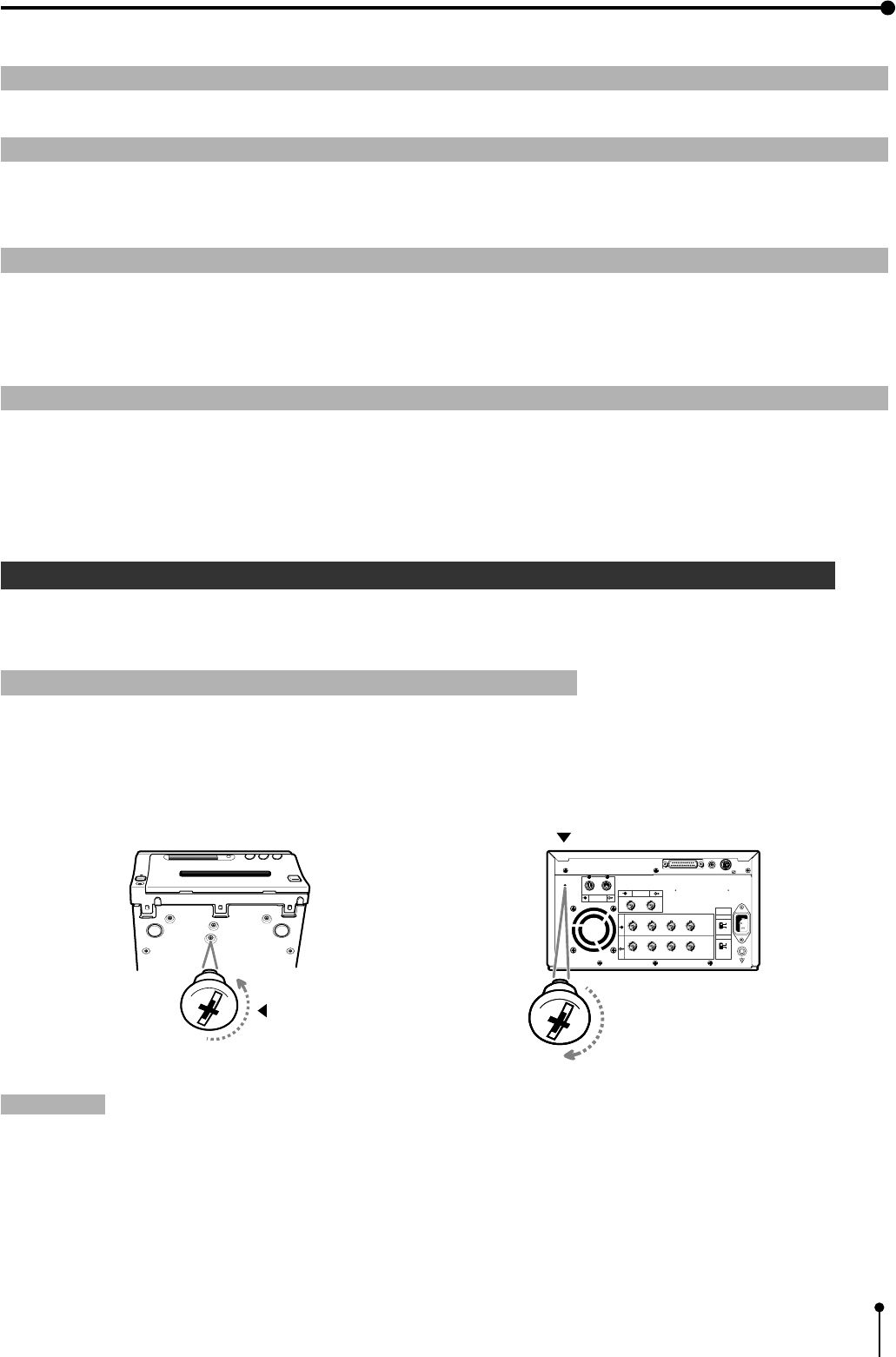
When using the unit for the first time, remove the fixed screw on the printing unit and protective cushion.
1 Remove the fixed screw on the printing unit.
,There is a fixed screw at the bottom of the printing unit.
1Remove the fixed screw with a screwdriver or coin.
2Set the removed screw to the hole on the rear panel for keep the screw.
Attention:
,Keep the removed fixed screw by setting it to the hole on the rear panel. This screw is required when transporting
this unit.
,Make sure you set the fixed screw to the bottom of the unit when transporting the printer.
Fixed screw
R G/G+SYNC B H+V-SYNC
R G/G+SYNC B H+V-SYNC
IN
OUT
S-VIDEO AC LINE
VIDEO
75Ω
HIGH
75Ω
HIGH
IMPEDANCE
SYNC.
RGB
RS-232C
Stored position
REMOTE
12
3. Preparations before operation
6
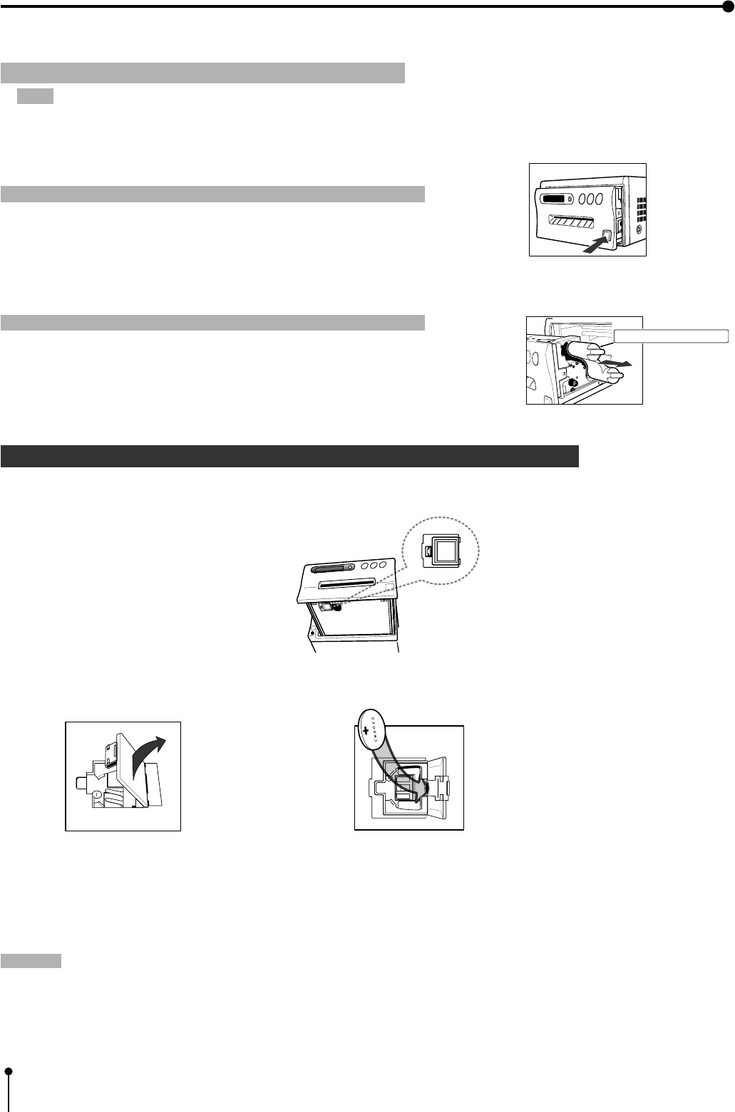
1Open the door. 2Install the battery with the (+) side facing out.
3Close the door.
1 Remove the protective cushion.
Note: Unplug the power cord from outlet for safety.
1Press the OPEN button on the front panel.
Printing unit will slide out.
Attention}}
}}
}
,Do not touch the thermal head.
Fingerprints or dust on the thermal head will degrade the print quality.
2Pull out the protective cushion from the right side.
Attention}}
}}
}
,Keep the protective cushion for transporting this unit.
,It is very important to transport this printer with the protective cushion
installed so as not to damage the printing unit.
2 Installing the lithium battery
Power for memory of day and present time are supplied by a lithium battery.
Install the lithium battery ( accessory CR2025) by the following procedure after plugging the VCP.
{ Install the lithium battery to the folder.
,If the installed battery is dead or a battery has been installed incorrectly, the built-in clock and power loss listing will not
function properly.
,When changing the battery, pry the battery out of the holder with a sharp object.
,After changing the battery, set the present time and day.
Note:
,Take care of the battery. Refer to pages on lithium battery precaution.
,The setting before installing the battery is not valid. When operating this unit without any settings, the strobe function
may not be operated.
Folder
Protective cushion
3. Preparations before operation
,If the installed battery is dead or a battery has been installed incorrectly, the built-in clock and power loss listing will not
function properly.
,When changing the battery, pry the battery out of the holder with a sharp object.
,After changing the battery, set the present time and day.
Note:
,Take care of the battery. Refer to pages on lithium battery precaution.
,The setting before installing the battery is not valid. When operating this unit without any settings, the strobe function
may not be operated.
7
3 Installing print paper and ink sheet
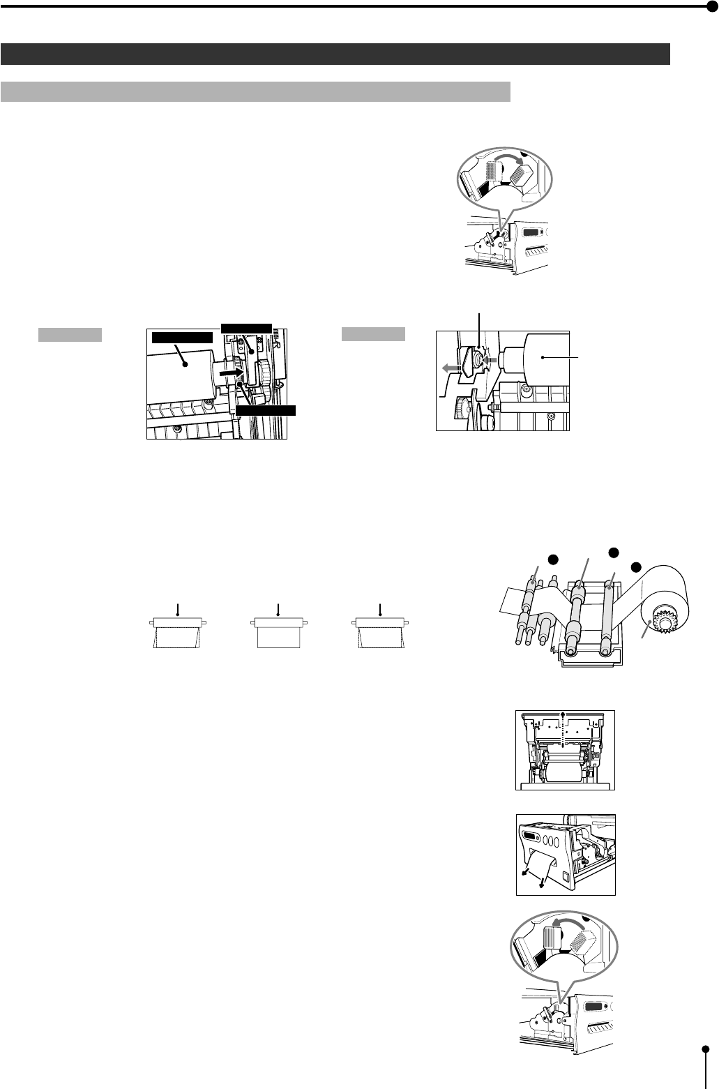
1 Installation procedure of print paper
1Move the knob on the printing unit to the direction indicated by the arrow.
2Insert the print paper in the position as shown below.
Place the gear to the right side.
Right side Left side
• Set the paper roll first on the right side paper holder.
• Set the paper roll on the left side paper holder.
3Insert the print paper between roller 1 and 2.
4Insert the edge of the print paper to roller 3.
Be sure to insert the paper straight.
5Feed the print paper through the exit slot straight with your hand.
6Pull the print paper to eliminate slack.
7Move the knob on the side of the printing unit to the direction as
indicated by the arrow.
3. Preparations before operation
Print paper Folder
Insert
Folder
Print paper
Roller Roller
Roller
Paper Paper Paper
INCORRECT CORRECT INCORRECT
1
Roller
2
Roller
3
Roller
Print paper
8
3. Preparations before operation
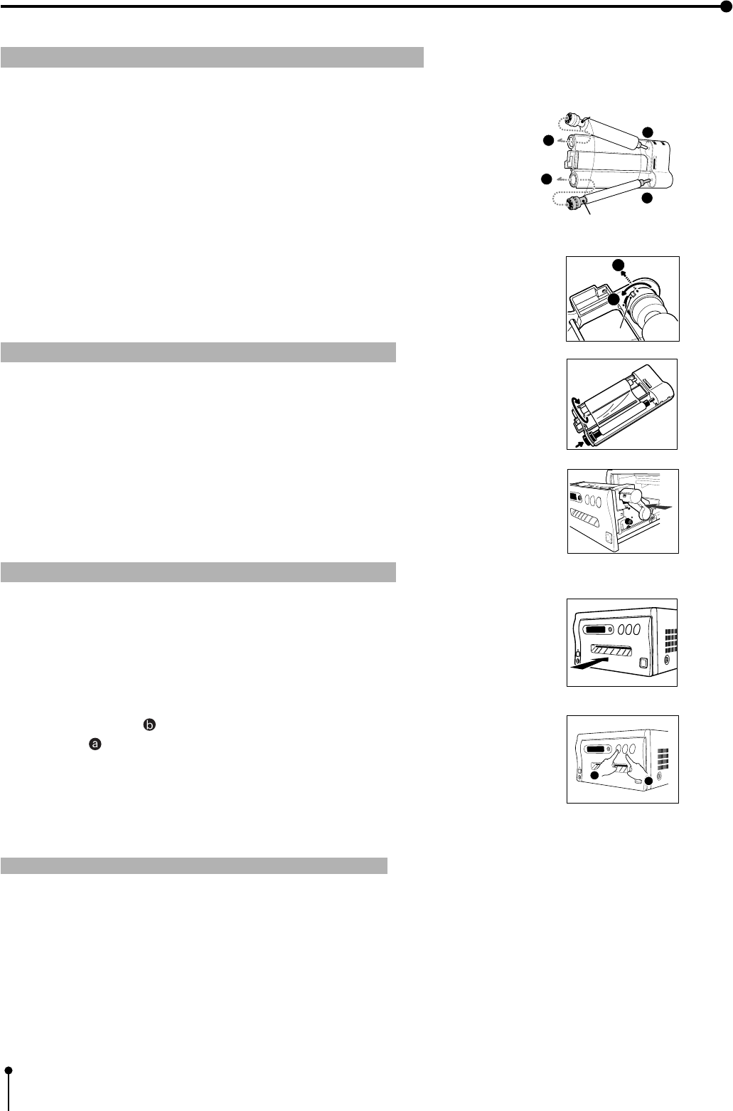
1 Install the ink sheet
Install the ink sheet to the ink cassette before installing the sheet cassette to the unit.
1Set the black roller of the ink sheet to ink cassette as shown right A, B.
2Set the thin stick of white roller to the ink cassette as shown right C.
3Set the thick stick of white roller of the ink cassette as shown right D, E.
In the step 3, turn the roller and set the notch of the roller side to the hole of
the cassette .
Install the roller by putting the notch through the hole.
1Install the ink cassette
1Eliminate any slack of the ink sheet.
Push the black roller and turn the white roller.
2Insert the ink cassette with the ink sheet into its compartment.
Insert the ink cassette with the knob side toward you.
1Set the printing unit
1Push the printing unit until it is locked into place.
2After plugging the power cord, press the “POWER” button on the front panel.
3Press the MEMORY ( ) button for about 1 second while pressing the
MONITOR ( ) button on the front panel .
,The print paper is automatically cut after sending by about 10cm.
4Repeat 3 step.
(Fingerprints and dust can be removed by feeding the print paper. The
printing unit is initialized.)
Attention}}
}}
}
,When setting the print paper, the set paper is a little pulled into the unit. Take care that any object is not pulled into
the unit with the print paper.
,In 2~3steps, press the “MONITOR” first. If MEMORY button is pressed first, the stored in memory may be cleared.
,Do not feed the print paper (2~3 steps) more than 2 times. Doing so will not arrow the number of prints indicated on page 9
to be printed.
,If the print paper is pulled out too much at installing, an error may occur with the display “PAPER JAM 12”. In this case, initialize
this unit again. (2~3 steps)
0 The installation of the print paper and ink sheet is completed.
White roller
Black roller
A
B
C
E
E
D
notch
ab

9
3. Preparations before operation
1 Print paper and ink sheet
Attention}}
}}
}
,The following types of paper sheet sets are available.
Use our original consumable. We can not guarantee the failure of using others.
Ink sheet
Product name Ink sheet size Number of prints Usage
PK700S S size 200 sheets For 3 color use
PK700L L size 130 sheets For 3 color use
Print-paper
Product name Print size Number of prints Usage
CK700 S / L size S size:200 sheets For 3 color use
L size:130 sheets
K65H S / L size S size:200 sheets For thermal printing
L size:125 sheets
K65HM S / L size S size:200 sheets For thermal printing
L size:125 sheets
Print-paper/ Ink sheet
Product name Print size Number of prints Usage
CK700S4P S size 110 sheets For 3 color use (Surface-coated paper)
CK700L4P L size 75 sheets For 3 color use (Surface-coated paper)
CK700SC S size 200 sheets For 3 color use (sticker)
CK700LC L size 130 sheets For 3 color use (sticker)
CK710SPC S size 200 sheets For 3 color use (16-division pre-cut sticker)
CK710LPC L size 130 sheets For 3 color use (16-division pre-cut sticker)
Ink sheet /Ink cassette
Product name Print size Number of prints Usage
PKC700S S size 200 sheets For 3 color use
PKC700L L size 130 sheets For 3 color use
Note:
,Please observe the following precautions.
Precautions before printing
0Fingerprints or dust on the paper’s printing surface may degrade print quality and cause paper jams. Immediately after the
paper is replaced, 2-3 images may be printed with a blank part due to hand’s dust or oil.
0When print paper is rapidly transferred from a cool place to a hot place, vapor or dew is generated on the paper’s surface
causing paper jams or degraded print quality. Leave the print paper in the room to stabilize its temperature before using it.
0When print paper and ink sheet runs out during printing, the printing operation stops and the error message “PAPER
EMPTY” or “SHEET EMPTY” is displayed. Replace the print paper and ink sheet with a new one.
0If paper feeding is repeated while installing the print paper, the indicated number of prints may not be done.
After printing
0When the printed paper is touched by a wet hand, the print may be discolored.
0If the paper absorbs non-volatile organic solvents ( alcohol, ester, ketone etc.) the print may be discolored.
0Discoloration of prints will be accelerated if the print paper comes into contact with soft vinyl chloride such as transparent
tape etc.
Storage
0Store the prints in a place with low humidity free from direct sunlight.
0Leaving the print paper in contact with PVC-based materials causes color of print paper to come off and to be stained.
0Avoid direct sunlight and placing the printed paper near a heater.
Note:
0If the print paper is installed for two or more days, the prints may be rolled after printing. There is no cause for alarm
because the print paper is rolled on the inside of the printing unit.
10
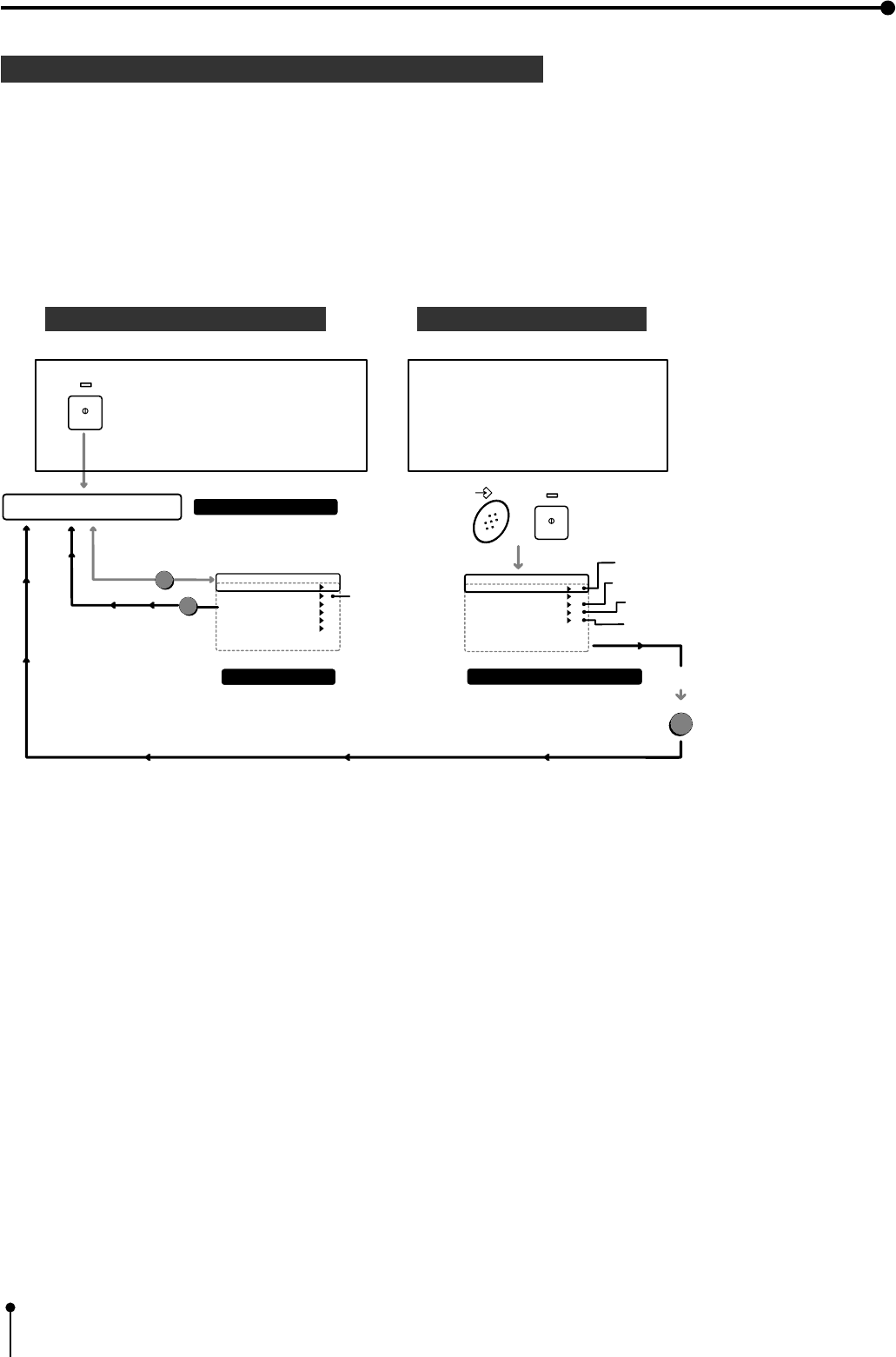
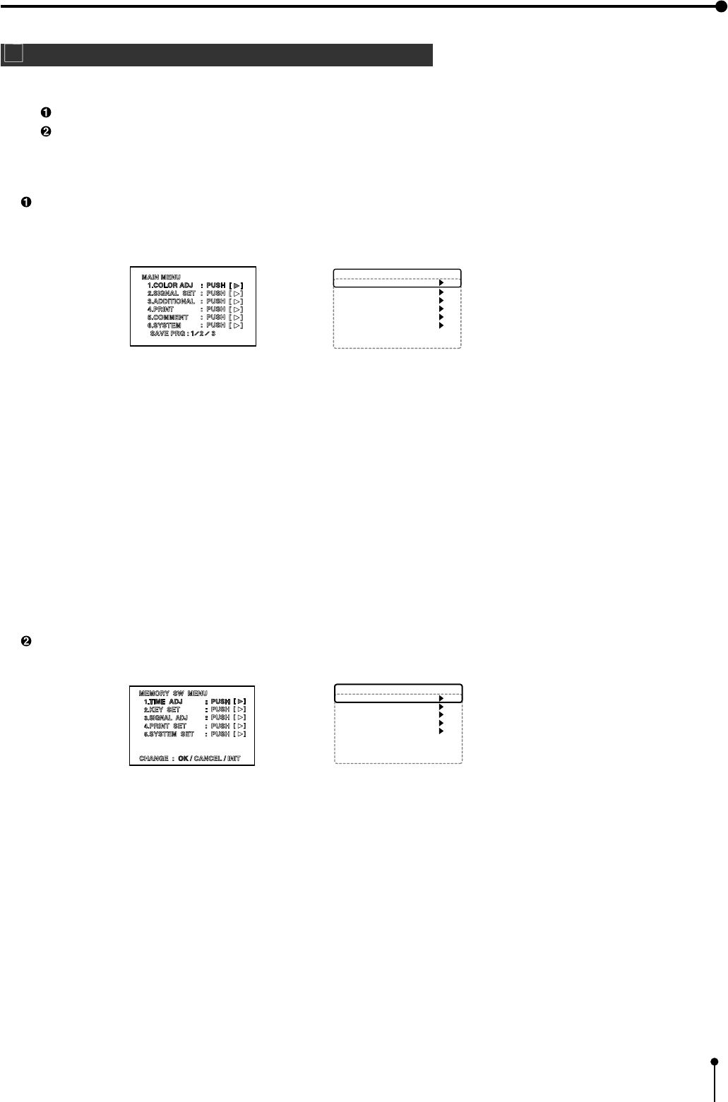
Menu display
When setting the day and present time , use the menu on the LCD display.
Also use the menu when selecting each setting after connecting an external device or selecting the print size (S /L).
,There are 2 menus, Main menu and Memory SW menu.
,Each menu is displayed as shown below.
MAIN MENU Memory SW menu
0 Setting the present time
Refer to pages 11-13.
0 Setting the polarity.
Refer to pages 15-16 .
0 Setting the print paper.
Refer to pages 31-32 .
0 Setting the baud rate.(RS-232C)
Refer to pages 19-21 .
0 Setting input signal.
Refer to pages 29-30.
,For each setting, refer to the pages above.
Use the remote control to set the functions.
3. Preparations before operation
Memory SW Main Menu
1.TIME ADJ : PUSH [ ]
2.KEY SET : PUSH [ ]
3.SIGNAL ADJ : PUSH [ ]
4.PRINT SET : PUSH [ ]
5.SYSTEM SET : PUSH [ ]
CHANGE : OK CANCEL INIT
MEMORY POWER
+
Pressing the POWER button to
display MEMORY SW menu
while pressing MEMORY button.
Press the menu button to
display the Main menu after
pressing POWER button.
Memory SW menu
MENU
NORMAL PRG.1 Q'ty 1
Page:A FIELD RGB
MAIN menu
Normal display
SET
POWER
Selecting the
input signal
Setting the day and present time
Setting the polarity
Setting the print paper
Setting the baud rate (
RS-232C)
SET
OK
Main Menu
1.COLOR ADJ : PUSH [ ]
2.SIGNAL SET
: PUSH [ ]
3.ADDITIONAL
: PUSH [ ]
4.PRINT : PUSH [ ]
5.COMMENT : PUSH [ ]
6.SYSTEM : PUSH [ ]
SAVE PRG : 1 / 2 / 3
11
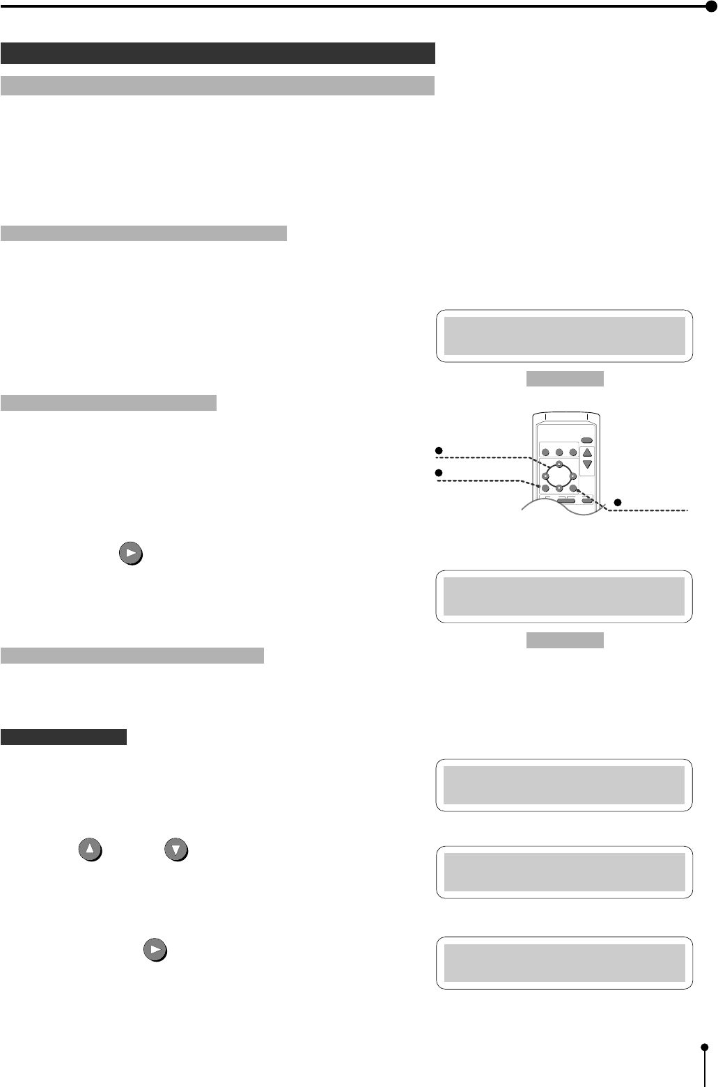
,Set the day and present time in the menu on the monitor display or LCD
display.
A . Display “Memory SW Main Menu”
,Make sure to turn off power.
1Press the POWER button while pressing the MEMORY button. Menu
display for button function “Memory SW Main Menu” is displayed.
B . Display “Time Adj Menu”
All these functions are operated with the remote control using the
menus displayed on the monitor screen.
2Press the RIGHT button.
,“Time Adj Menu” is displayed.
Set the day and present time on the menu.
4 Setting the present time
1 Setting the day and present time
Set the day and present time on the lower part of the print by the following
procedure.
3. Preparations before operation
Memory SW Main Menu
1.TIME ADJ :PUSH[>]
PRINT
Q' ty
SET button
SHIFT buttons
MENU button
PROG.
MENU
CLEAR STOP
SET
COLOR FIELD
ADJUST /FRAME
DISPLAY
-
+
Time Adj Menu
DATE : 28
Time Adj Menu
MONTH : 01
C . Setting the day and present time
• Setting part is displayed in red on the monitor.
Setting the day
,“DATE” is indicated on the LCD display.
3Press UP or DOWN button to change the value.
4Press the shift button .
Date is set and “MONTH” is displayed on the LCD .
Time Adj Menu
DATE : 01
Time Adj Menu
DATE : 01
LCD display
LCD display
12
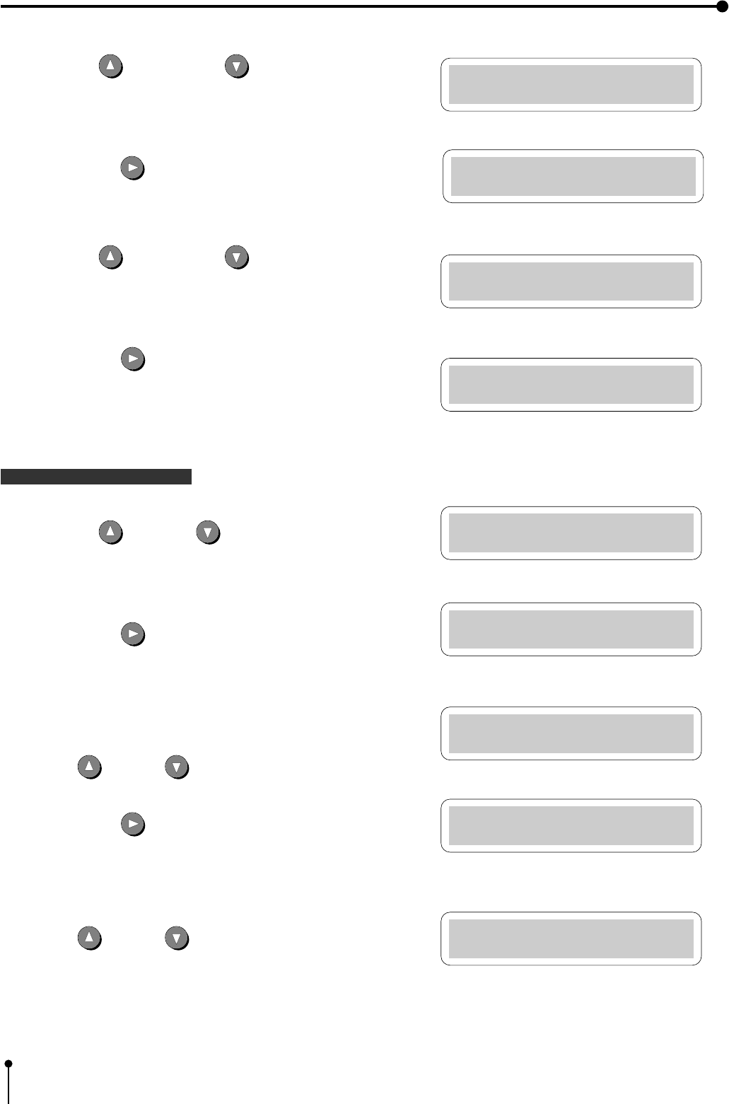
5Press the UP button or DOWN button to change the value.
6Press the RIGHT button. The month is set and display the “YEAR”.
,The “YEAR” is displayed on the LCD .
7Press the UP button or DOWN button to change value.
8Press the RIGHT button.
,The day is set and the present time is displayed.
The “HOUR” is displayed on the LCD .
Setting the present time
9Press the UP and DOWN button to change the value.
APress the RIGHT button.
,“HOUR” is set and the “MINUTE” is displayed.
The “MINUTE” is displayed on the LCD.
BPress UP or DOWN button to change the value.
CPress the RIGHT button.
,The “MINUTE” is set and the “SECOND” is displayed .
The “SECOND” is displayed on the LCD.
DPress UP or DOWN button to change the value.
3. Preparations before operation
Time Adj Menu
MONTH : 08
Time Adj Menu
YEAR : 95
Time Adj Menu
HOUR : 00
Time Adj Menu
HOUR : 05
Time Adj Menu
MINUTE: 00
Time Adj Menu
MINUTE: 10
Time Adj Menu
SECOND: 00
Time Adj Menu
SECOND: 10
Time Adj Menu
YEAR : 99
13
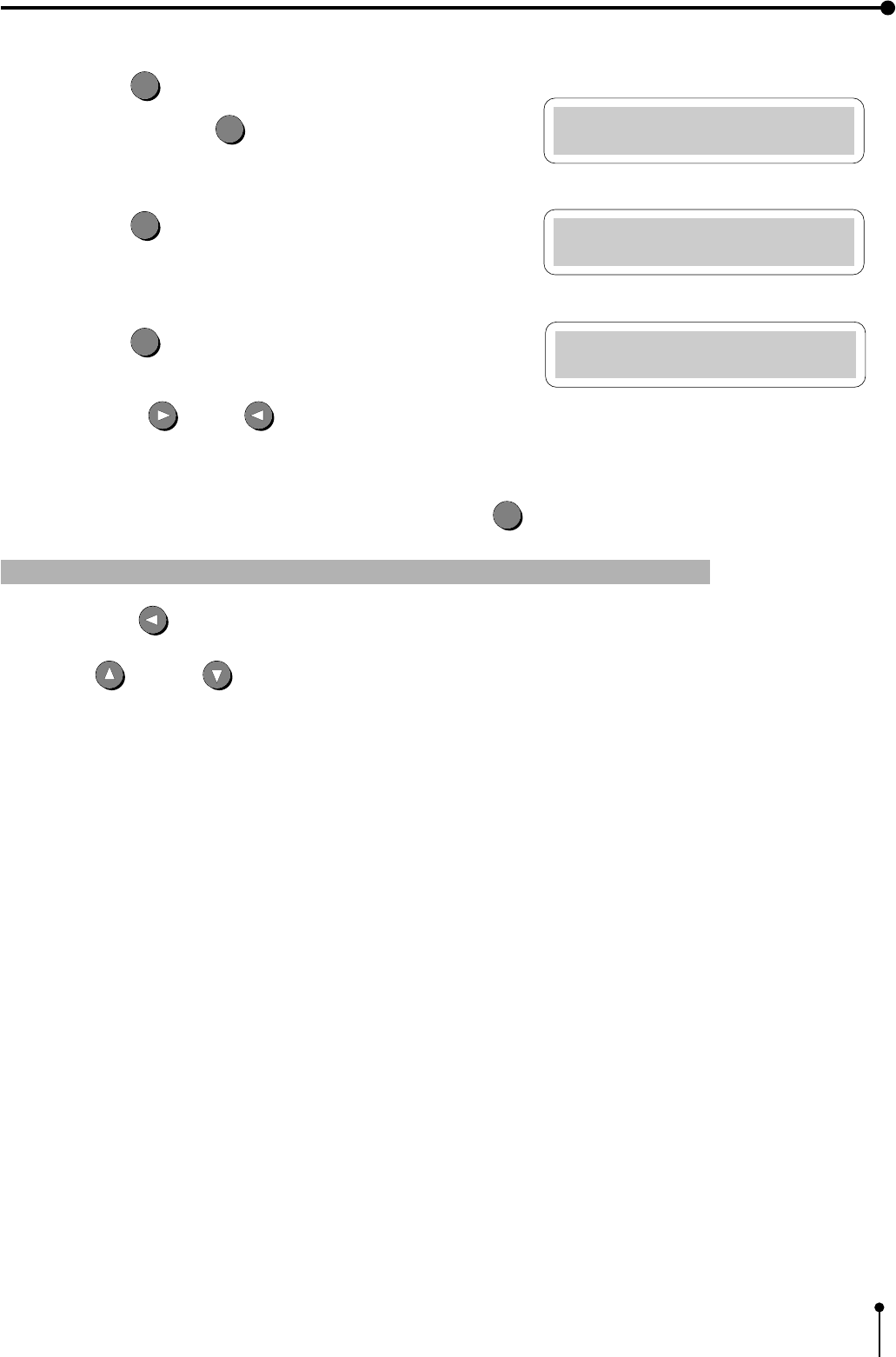
,The source image is shown when selecting OK and press the SET
SET
button.
1 Change the date and present time setting
,When the LEFT button is pressed during setting the date and present time, the cursor moves to the previous step.
Press UP or DOWN button to change the value.
,Date and present time setting is completed.
3. Preparations before operation
Time Adj Menu
SECOND: 31
Memory SW Main Menu
1.TIME ADJ :PUSH[>]
Memory SW Main Menu
CHANGE: OK
EPress the SET
SET
button.
,When pressing the SET
SET
button, the present time function will
be started.
FPress the SET
SET
button.
,“Memory SW Main Menu” display is shown.
GPress the SET
SET
button.
“CHANGE : OK” is selected.
,Press the RIGHT or LEFT button to select “OK” or
“CANCEL” according to the setting.
14
4. Connection with external equipment
The functions of this unit can be set with the menu screens displayed on the monitor.
1 Connection with Monitors Pages 14 - 16
Explains how to connect with a monitor.
Explains the setting of sync. polarity.
,When the sync. polarity of a monitor differs from the initial setting of this unit, the image on the monitor may not be
displayed correctly. In this case, set the sync. polarity according to the monitor.
When the image is displayed on the monitor correctly, the setting is not required.
2 Connection with VIDEO/S-VIDEO (Y/C separate VIDEO) signal equipment Page 17
Explains how to connect with a video signal equipment.
Explains how to connect with a S-video signal equipment.
3 Connection with RGB Analog Signal equipment Page 18
Explains how to connect with a RGB analog signal equipment.
4 Connection with RS-232C equipment Pages 19 - 21
Explains how to connect with a RS-232C equipment.
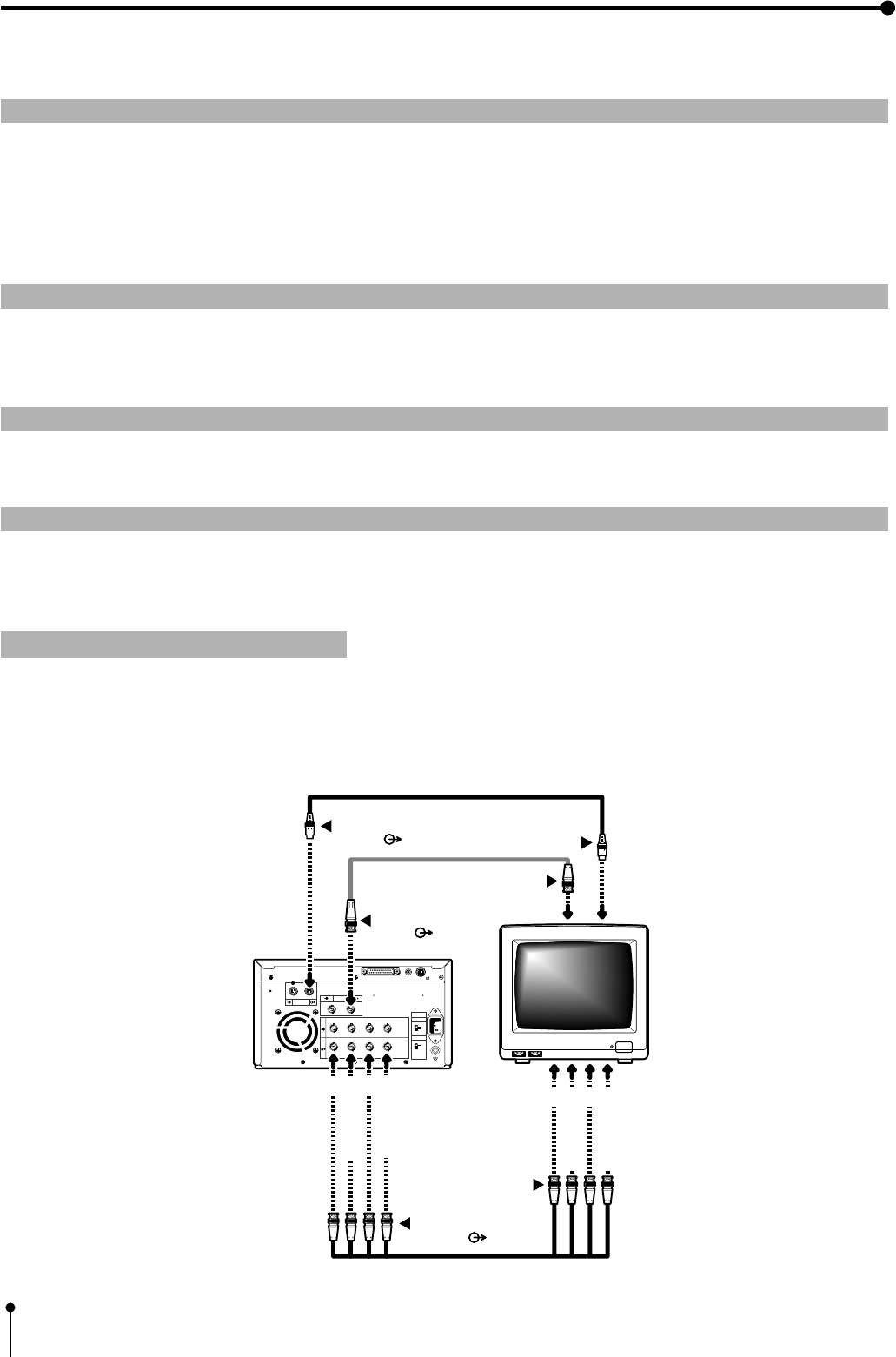
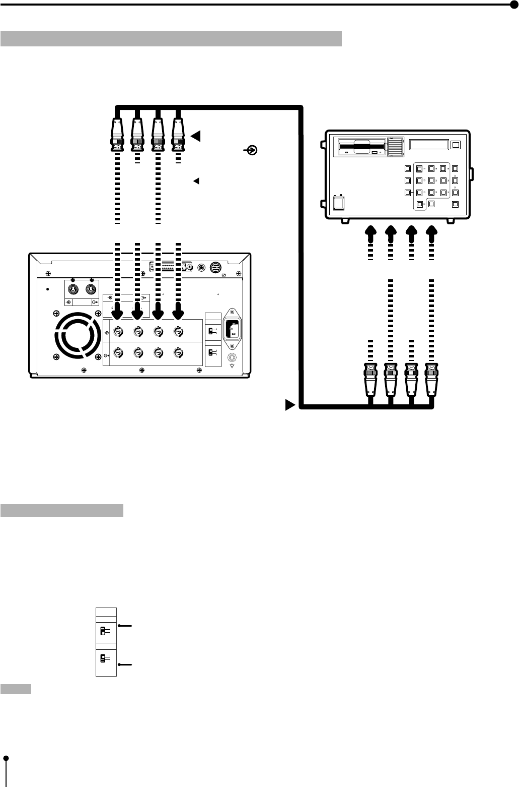
1 Connection with Monitors
Connect this unit with a monitor to check the images to be printed and the images stored in memory.
The following example shows the connection with a video signal, a S-video signal and RGB analog signal equipment.
Connect with the necessary signal equipment.
When connecting the unit with a monitor, make sure to set the power of each equipment to “OFF” .
To VIDEO OUT termi nal
VIDEO ( )
AC LINE
R G/G+SYNC B H+V-SYNC
R G/G+SYNC B H+V-SYNC
IN
OUT
S-VIDEO
VIDEO
75Ω
HIGH
75Ω
HIGH
IMPEDANCE
SYNC.
RGB
RS-232C
R
G/G+SYNC.
B
H+V-SYNC.
R
G/G+SYNC.
B
H+V-SYNC.
To S-VIDEO OUT terminal
S-VIDEO ( ) To S-VIDEO IN terminal
To RGB Analog OUT
terminals ( )
To RGB Analog IN
terminals
Monitor
VCP
To VIDEO IN terminal
REMOTE
12
15
4. Connection with external equipment (Monitor)
Setting the sync. polarity and output sync. signal
When the sync. polarity or sync. signal of a monitor to be connected is not adjusted to the initial setting of this unit, the image
may not be displayed correctly. In this case, adjust the sync. polarity and sync. signal output to the monitor.
When the image is displayed correctly, the setting is not required. (Refer to the operation manual of the monitor as for the sync.
polarity and sync. signal of the monitor.)
Displaying the menu
,The sync. polarity and sync. signal is set by the menu displayed on LCD.
,Make sure to turn off the power before setting.
Displaying “Memory SW Main Menu”
1Press the POWER button while pressing the MEMORY button on the front
panel.
The menu for memory switch “Memory SW Main Menu” is displayed.
Displaying “Signal Adj Menu”
}Use the buttons on the remote control to display and set the items in this
menu.
2Press the DOWN button to select “3. SIGNAL ADJUST : PUSH
[ ] ]” menu.
3Press the RIGHT button.
,The menu for signal setting, “Signal Adj Menu” is displayed.
,The sync. polarity, “SYNC” and output sync signals, “OUTPUT SYNC”
and “RGB SOG OUT” can be set in this menu.
Setting the sync. polarity “SYNC : NEGA POSI”
4Press the UP or DOWN button to select “SYNC” .
,In the initial setting, “IN SYNC” is selected in “3.SIGNAL ADJ : PUSH
[ ] ]” . When other menu is selected, press the UP or DOWN
button to select “SYNC” .
The sync. polarity being selected, for example, “NEGA” is displayed.
Press the RIGHT or LEFT button to select “NEGA” or
“POSI” according to the polarity of the equipment to be connected.
Memory SW Main Menu
1.TIME ADJ :PUSH[>]
LCD
Memory SW Main Menu
3.SIGNAL ADJ:PUSH[>]
Signal Adj Menu
IN SYNC : TTL,SOG
Signal Adj Menu
SYNC : NEGA
16
4. Connection with external equipment (Monitor)
Setting the output sync. signal “OUTPUT SYNC”
5Press the DOWN or UP button to select “OUT SYNC”.
,The set level of the sync. signal, for example, “0.3V” is displayed.
Set the sync. signal according to the equipment to be connected.
Press the RIGHT or LEFT button to select “0.3V” or
“TTL”.
0.3V ...... 0.3Vp-p
TTL .... TTL level
Setting the output RGB Analog signal “RGB SOG OUT”
6Press the DOWN or UP button to select “RGB SOG OUT”.
7Press the RIGHT or LEFT button to select “ON” or “OFF”.
OFF...... Outputs Composite Sync. signal
ON ...... Outputs Sync. On Green + Composite Sync. signal.
Select “ON” or “OFF” according to the monitor to be connected.
8Press the SET
SET
button.
,“CHANGE : OK/CANCEL” is selected.
Press the RIGHT or LEFT shift button to select “OK” or
“CANCEL” .
9Select “OK” , then press the SET
SET
button.
,“Memory SW Main Menu” is displayed.
APress the SET
SET
button.
,“CHANGE : OK” is selected.
BSelect “OK” , then press the SET
SET
button.
,The source image (input signal from the equipment) is displayed.
0 The setting of the sync. polarity and signal is completed.
Signal Adj Menu
OUT SYNC:TTL
Signal Adj Menu
RGB SOG OUT:OFF
Signal Adj Menu
CHANGE : OK
Memory SW Main Menu
3.SIGNAL ADJ:PUSH[>]
17
4. Connection with external equipment (VIDEO/S-VIDEO)
AC LINE
R G/G+SYNC B H+V-SYNC
R G/G+SYNC B H+V-SYNC
IN
OUT
S-VIDEO
VIDEO
75Ω
HIGH
75Ω
HIGH
IMPEDANCE
SYNC.
RGB
RS-232C
To VIDEO IN terminal
VIDEO ( )
To VIDEO OUT terminal
VCP
VIDEO signal
equipment
REMOTE
12
CCD COLOR VIDEO CAMERA CCD-200E
AC LINE
R G/G+SYNC B H+V-SYNC
R G/G+SYNC B H+V-SYNC
IN
OUT
S-VIDEO
REMOTE
VIDEO
75Ω
HIGH
75Ω
HIGH
IMPEDANCE
SYNC.
RGB
RS-232C
CONFORTABLE LD PLAYER DP-L2000
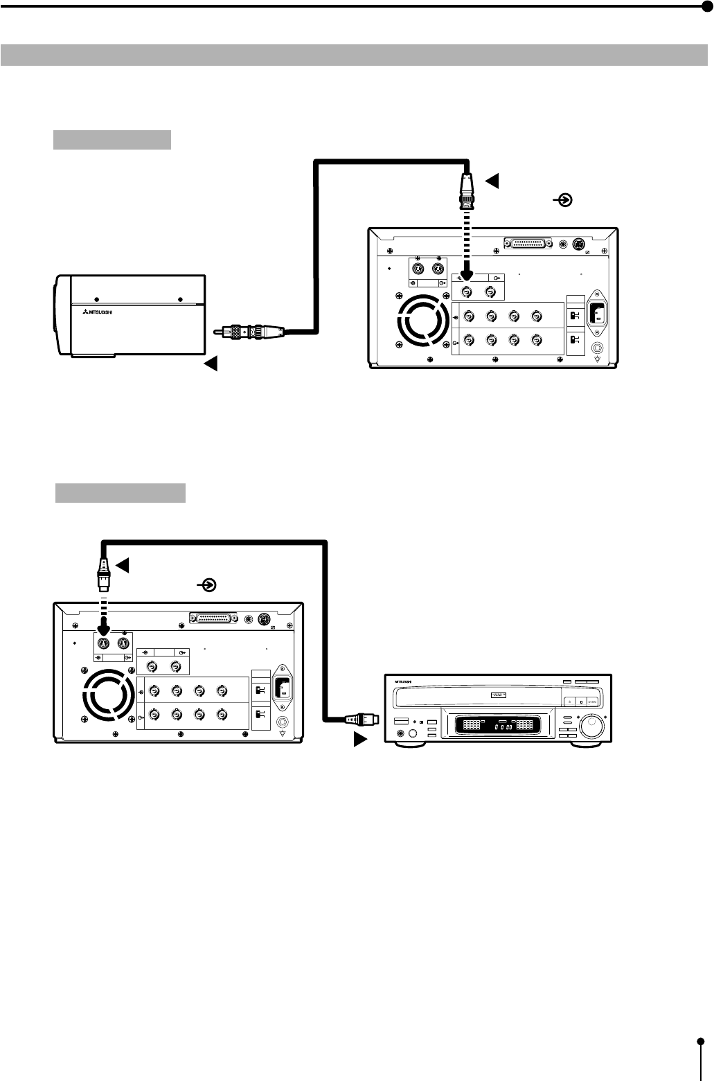
To S-VIDEO IN terminal
S-VIDEO ( )
To S-VIDEO OUT terminalVCP
S-VIDEO signal equipment
12
2
Connection with VIDEO signal, S-VIDEO (Y/C separate VIDEO) signal equipment
When connecting the unit with another equipment, make sure to set the power of each equipment to “OFF”.
VIDEO signal
S-VIDEO signal
18
4. Connection with external equipment (RGB Analog signal)
3 Connection with RGB Analog Signal equipment
, When connecting the unit with another equipment, make sure to set the power of each equipment to “OFF”.
,Use BNC type cable on the market for connection.
,This unit functions at 15.625 kHz for H and 50Hz for V.
Setting the switches
,Set the impedance switches “IMPEDANCE” on the rear panel to the impedance of the equipment connected.
Normally,
a.Set the RGB analog signal to “75Ω”.
b.Set the sync signal to “HIGH.
NOTE: • When the power turns off or the display is not appeared with analog through mode, the impedance switch is not
available. So, connect the unit with the side of monitor or external terminal .
• When connecting to a monitor, use the monitor with 75Ω.
75Ω
HIGH
75Ω
HIGH
IMPEDANCE
SYNC.
RGB
Impedance switch for RGB analog signal
Impedance switch for sync. signal
AC LINE
R G/G+SYNC B H+V-SYNC
R G/G+SYNC B H+V-SYNC
IN
OUT
S-VIDEO
VIDEO
75Ω
HIGH
75Ω
HIGH
IMPEDANCE
SYNC.
RGB
RS-232C
RECORD
REPLAY
10 KEY
RED
GREENGREEN
BLUEBLUE
CONTRAST
BRIGHTNESSBRIGHTNESS
SCAN SPEED
RESETRESET WHITE
BALANCE
SCAN START
POWER
ON OFF
R
G/G+SYNC.
B
H+V-SYNC.
To RGB Analog OUT terminal
R
G/G+SYNC.
B
H+V-SYNC.
To RGB Analog IN
terminal ( )
VCP
RGB Analog signal equipment
In case of SYNC ON G.
signal, it is not
necessary to connect to
the unit.
REMOTE
12
19
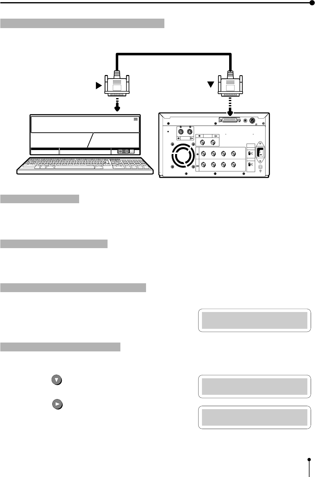
4. Connection with external equipment (RS-232C Interface)
4 Connection with RS-232C equipment
, When connecting the unit with another equipment, make sure to set the power of each equipment to “OFF”.
Setting BAUD RATE
Set the baud rate of this unit according to the equipment to be connected.
,As to the baud rate of the equipment connected, refer to the operation manual of the equipment connected.
Displaying the menu screen
,
The baud rate is set on the menu displayed on the monitor screen or LCD. (The following is an example of display on LCD.)
,Make sure to turn off the power before setting.
Displaying “Memory SW Main Menu”
1Press the POWER button while pressing the MEMORY button on the
front panel.
,The menu for memory switch, “Memory SW Main Menu” is displayed.
Displaying “System Set Menu”
} Use the buttons on the remote control to display and set this menu.
2Press the DOWN button to select “5. SYSTEM SET : PUSH
[ ] ]” .
3Press the RIGHT button.
,The menu for signal setting, “System Set Menu” is displayed.
,Set “BAUD RATE” on this menu.
Memory SW Main Menu
1.TIME ADJ :PUSH[>]
Memory SW Main Menu
5.SYSTEM SET:PUSH[>]
System Set Menu
PRG ALL INIT : OFF
AC LINE
R G/G+SYNC B H+V-SYNC
R G/G+SYNC B H+V-SYNC
IN
OUT
S-VIDEO
VIDEO
75Ω
HIGH
75Ω
HIGH
IMPEDANCE
SYNC.
RGB
RS-232C
To RS-232C port
(RS-232C)
To RS-232C port
VCP
Equipment with RS-232C
REMOTE
12
20
4. Connection with external equipment (RS-232C Interface)
Setting BAUD RATE
1Press the DOWN or UP shift buttons to select “BAUD RATE”.
The set baud rate, for example, “9600” , is displayed.
Press the RIGHT or LEFT SHIFT button to select “1200” ,
“2400” , “4800” or “9600” Bit/Sec) .
2Press the SET
SET
button.
,“CHANGE : OK” is selected.
,Press the RIGHT or LEFT shift button to select “OK” or
“CANCEL” .
3Select “OK” , then, press the SET
SET
button.
,“Memory SW Main Menu” is displayed.
4Press the SET
SET
button.
,“CHANGE : OK” is selected.
5Select “OK”, then, press the SET
SET
button.
,The source image (input signal from the equipment connected) is displayed.
0The setting of BAUD RATE is completed.
System Set Menu
BAUD RATE : 9600
System Set Menu
CHANGE : OK
Memory SW Main Menu
5.SYSTEM SET:PUSH[>]
System Set Menu
COMMAND TYPE : A
System Set Menu
CHANGE : OK
Memory SW Main Menu
5.SYSTEM SET:PUSH[>]
Setting the RS-232C COMMAND TYPE
Select “A” or “B” according to the equipment connected.
1Press the DOWN or UP buttons to select “COMMAND TYPE” .
Press the RIGHT or LEFT SHIFT button to select “A” or “B”.
2Press the SET
SET
button.
,“CHANGE : OK” is selected.
,Press the RIGHT or LEFT button to select “OK” or
“CANCEL” .
3Select “OK” , then, press the SET
SET
button.
,“Memory SW Main Menu” is displayed.
21
4. Connection with external equipment (RS-232C Interface)
4Press the SET
SET
button.
,“CHANGE : OK” is selected.
5Select “OK”, then, press the SET
SET
button.
,The source image (input signal from the equipment connected) is displayed.
0The setting of COMMAND TYPE is completed.
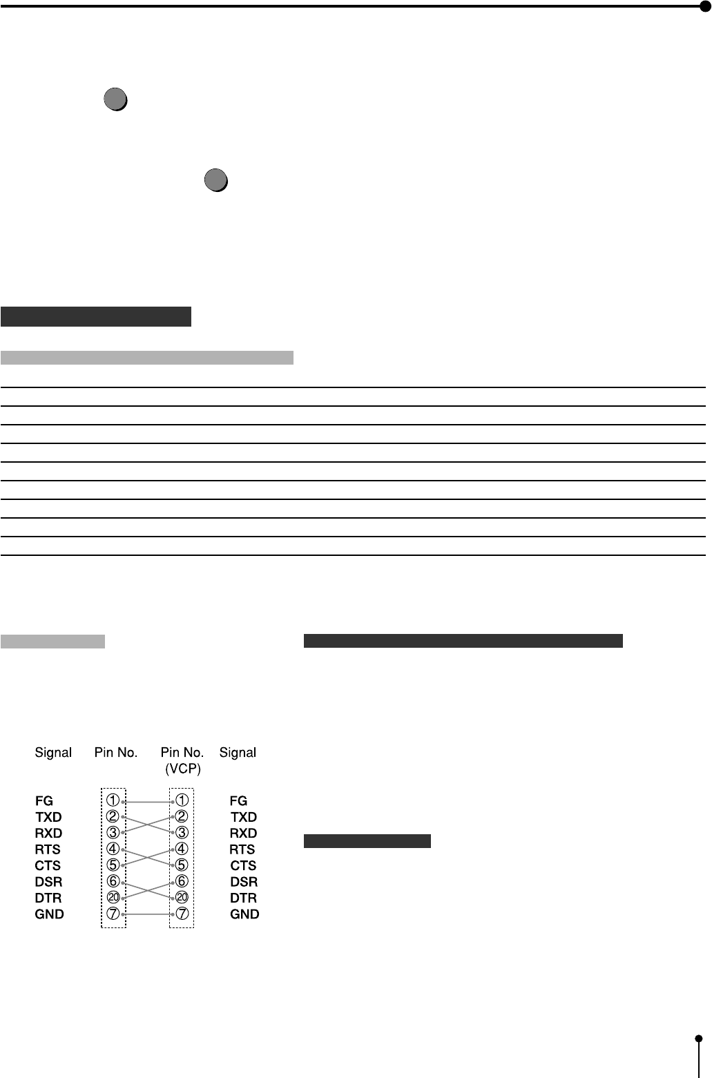
RS-232C DATA SIGNAL
RS-232C input connector port signal allocation
Pin No. Signal line name Description Directions (From VCP side)
1 F G Protective ---
2 T X D Transmitted data Output
3 R X D Received data Input
4 R T S Request to send Output
5 C T S Clear to send Input
6 D S R Data set ready Input
7 G N D Signal ground ---
20 D T R Data terminal ready Output
Setting the communication format of the computer
,Set the communication format as follows:
(1) Synchronizing system Asynchronous communication
(2) Data bit length 8 bits
(3) Parity bit Nothing
(4) STOP bit length 1
(5) Transmission order Sent from LSB
(6) Baud rate (Bit / Sec) 1200, 2400, 4800, 9600
RS-232C function
,This unit can be controlled through RS-232C terminal.
( The input of image data is not possible.)
Consult with the sales dealer for the details of controlling
method (protocol).
Pin connection
,Connect the unit with the host computer
through cross-over cable.
Cross-over cable
22
5. Features and functions
1 FRONT PANEL pages 22 - 23
Explains the buttons and terminals, etc. on the front panel.
2 INSIDE OF PRINTING UNIT page 23
Explains the installation of the ink cassette, print paper and battery inside the unit.
3 REAR PANEL page 24
Explains input/output terminals on the rear panel.
4 REMOTE CONTROL pages 25 - 26
Explains the functions of the buttons on the remote control.
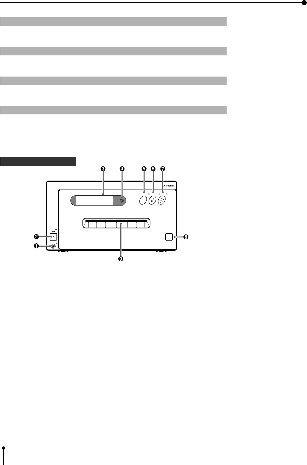
1 FRONT PANEL
1Remote terminal [REMOTE]
Connect the remote control of the printer in this terminal.
The remote control cannot be worked when connecting to the “REMOTE 1” terminal on the rear panel.
2Power button [POWER]
Press this button to turn on and off the power. When power is turned on, the indicator lights up.
3LCD display
Displays the set conditions of the input signal, and used to set various functions.
(The menus displayed on the monitor or LCD are used to set various settings.Refer to pages 37 - 64. )
4LCD contrast control [LCD CONTRAST]
Adjusts the contrast of the LCD. Turn this control by pressing with a finger. Set the contrast so that you can see the
displayed characters easily.
5Monitor button [MONITOR]
Switches the display on the monitor. When this button is pressed, the picture on the monitor screen switches between the
picture of the input signal (source image) and the memorized image.
OPEN
MEMORY PRINT
POWER
REMOTE
MEMORY PRINT
MONITOR
23
5. Features and Functions
6Memory button [MEMORY]
This enables memorization of the image to be printed.
7Print button [PRINT]
Press this button to print the images memorized by the MEMORY button. A green lamp will light during printing. The screen
switches to the picture of the input signal.
8Open button [OPEN]
When this button is pressed, the printing unit will slide out. The printing unit is used when loading ink cassette and
printing paper or overcoming paper jams.
9Print outlet
The printed paper come out here.
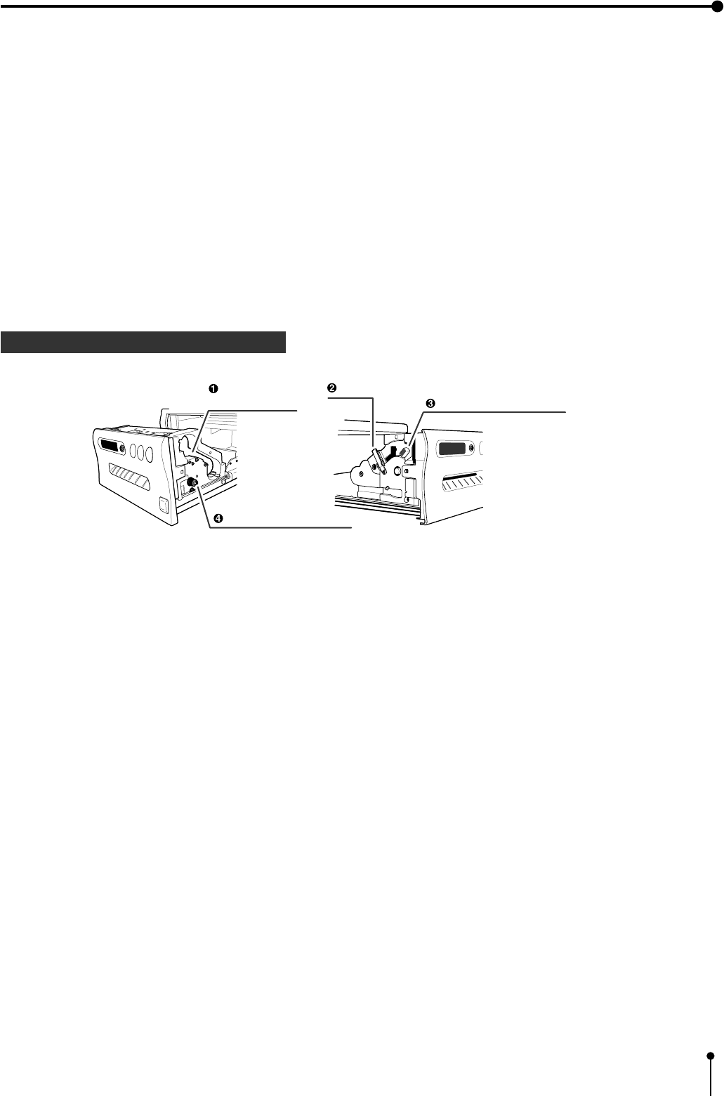
2 INSIDE OF PRINTING UNIT
1Ink cassette compartment
Load the cassette with ink sheet.
2Ink cassette locking lever
Push this lever to take the ink cassette out.
3Print paper fixing lever
Use this lever when inserting print paper.
4Paper sending control
Turn this control clockwise to rewind the print paper.
Ink cassette
compartment
Ink cassette locking lever
Print paper fixing lever
Paper sending control
24
5. Features and Functions
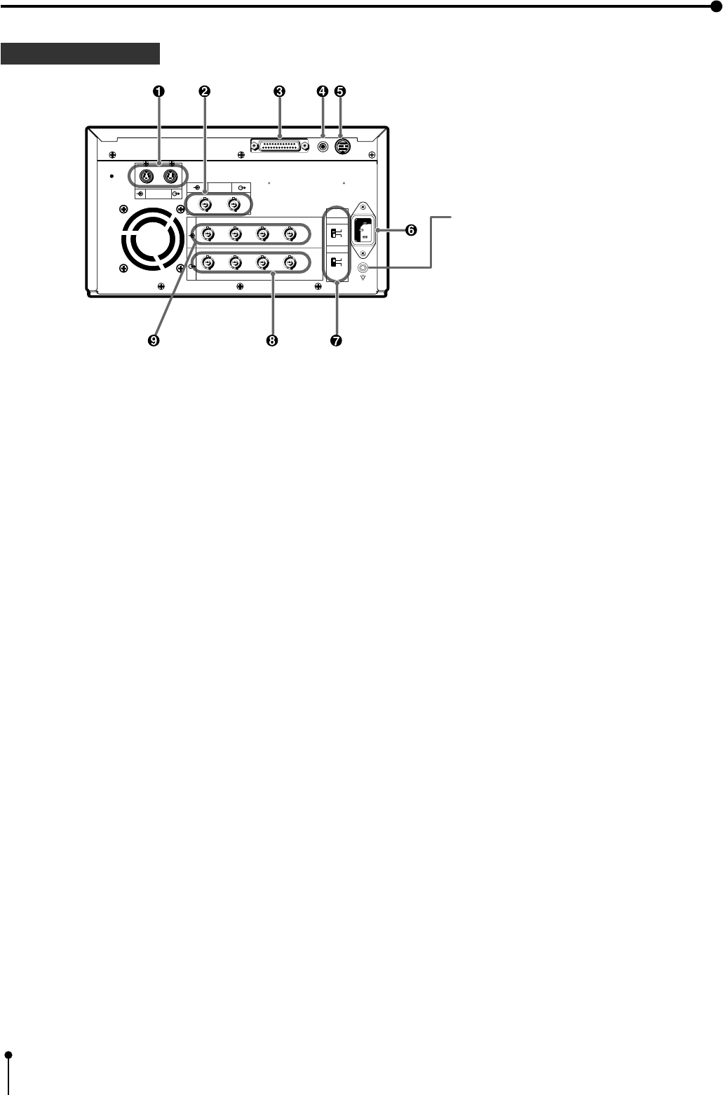
1S-VIDEO SIGNAL INPUT/OUTPUT TERMINALS [S-VIDEO]
Use these terminals to connect this unit to S-VIDEO signal equipment.
Refer to page 17 for connection.
2VIDEO INPUT/OUTPUT TERMINALS [VIDEO]
Use these terminals to connect this unit to VIDEO signal equipment.
Refer to page 17 for connection.
3RS-232C PORT [RS-232C]
Use this terminal to connect this unit to a device equipped with RS-232C interface.
Refer to pages 19 - 21 for connection.
4EXTERNAL REMOTE TERMINAL [REMOTE 1]
Memorizing images are available by the remote signal inputted through this terminal. It is necessary to make a circuit for
remote control to use the function.
Refer to page 83.
5EXTERNAL REMOTE TERMINAL [REMOTE 2]
Memorizing images and printing are available by the remote signal inputted through this terminal. It is necessary to make a
circuit for remote control to use the function.
Refer to pages 81 - 83.
6POWER SOCKET [AC LINE]
This socket connects to the power cord (accessory).
Insert the cord firmly.
7IMPEDANCE SELECTION SWITCH [IMPEDANCE RGB, SYNC. ]
This is a 75Ω / HIGH impedance selection switch for RGB or Sync. signal.
8RGB ANALOG OUTPUT TERMINALS [R,G/G+SYNC, G,H+V-SYNC]
This is a BNC type output terminal for a RGB analog signal. Sync. signal can be selected between 0.3V(H+V-SYNC.) and
TTL(H+V-SYNC.) signals.
Refer to page 18 for connection.
9RGB ANALOG INPUT TERMINALS [R,G/G+SYNC , B,H+V-SYNC ]
This is a BNC type input terminal for a RGB analog signal. The sync. signal can be automatically selected between H/V
composite and SYNC. ON GREEN (sync. signal imposed on the green video signal) signals. Refer to page 18 for switch
setting.
3 REAR PANEL
R G/G+SYNC B H+V-SYNC
R G/G+SYNC B H+V-SYNC
IN
OUT
S-VIDEO
REMOTE
AC LINE
VIDEO
75Ω
HIGH
75Ω
HIGH
IMPEDANCE
SYNC.
RGB
RS-232C
12
Potential equalization connector
This is used to equalize the potential of the equipment
connected to the unit.
For details, refer to the installation instruction of the
equipment to be connected.
25
5. Features and Functions
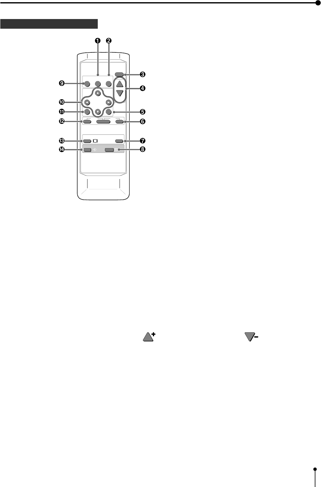
1COLOR IMAGE ADJUSTMENT button [COLOR ADJUST]
When this button is pressed, a screen for adjusting the video image is displayed. Use this button to set the various functions
of this unit. (The menus displayed on the monitor or LCD is used to set the various settings. Refer to Pages 45 - 46.)
2FIELD/FRAME button [FIELD / FRAME]
Press this button to switch the input signal between the FRAME or FIELD mode.
Every time this button is pressed, the mode is switched in the order of “FIELD”, “FRAME” and “FIELD”.
3DISPLAY button [DISPLAY]
When this button is pressed, the set conditions are displayed on the monitor screen. Press it again so that the display is not
shown.
4PRINT QUANTITY button [PRINT Q'ty]
This button is used to set the number of prints. Press button to increase the number and button to decrease.
5SET button [SET]
Use this button to set the various functions of this unit. For example, use it to fix the setting and return to the normal display from
the menu screen. (The menus displayed on the monitor or LCD is used to set the various settings. Refer to pages 42 - 43.)
6STOP button [STOP]
Press this button and the button to the left side of STOP button at the same time to cancel the printing process. The image
is printed out in the state when the printing was cancelled.
7MEMORY PAGE button [MEMORY PAGE]
This button is used to select the image memorized by the MEMORY button. Every time this button is pressed, the memory
page is switched.
4 REMOTE CONTROL
PROG.
MENU
CLEAR
MONITOR
MEMORY
MEMORY
PAGE
STOP
SET
COLOR FIELD
ADJUST /FRAME
DISPLAY
PRINT
Q' ty
-
+
PRINT

26
5. Features and Functions
8PRINT button [PRINT]
Press this button to print the image memorized by the MEMORY button. The image on the monitor screen is switched to the
picture of the input signal.
9PROGRAM button [PROG.]
Press this button to select the images memorized in the program of this unit and various settings such as printing.
Each time this button is pressed, the program is switched. This unit has 3 kind of programs and they can be changed and
stored voluntarily.
Programs cannot be changed during printing.
ASHIFT buttons
These buttons are used to change settings, such as selecting a function and moving to the next menu. (The menus displayed
on the monitor or LCD is used to set the various settings. Refer to pages 42 - 43.)
BMENU button [MENU]
Press this button to display the main menu.
This button is used to set the various settings.(The menus displayed on the monitor or LCD is used to set the various
settings. Refer to pages 42 - 43.)
CCLEAR button [CLEAR]
Press this button and the right side button at the same time to eliminate all or a part of memorized images.
DMONITOR button [MONITOR]
When this button is pressed, the picture on the monitor screen switches between the picture of the input signal and the
memorized image.
EMEMORY button [MEMORY]
This enables memorization of the image to be printed.

27
6. Printing procedures (Basic prints)
1 Printing Pages 28 - 34
Explains storing an image in the memory and printing
2 Continuous printing Pages 35 - 36
Explains the continuous printing of the same image.
{ S size printing { L size printing
One picture image can be printed on one sheet.
28
6. Printing Procedures (Basic prints)
1 Printing
1 Selecting FIELD or FRAME
1Press the FIELD/FRAME button on the remote control to select FIELD or FRAME.
PRINT
Q' ty
PROG.
MENU
CLEAR STOP
SET
COLOR FIELD
ADJUST /FRAME
DISPLAY
-
+
FIELD/FRAME button
,Select the FRAME mode for a high resolution still image printing.
Select the FIELD mode for a picture of quickly moving objects.
,When the FIELD mode is selected, the print image will be lower in
resolution.
The selected mode is displayed on the monitor screen and LCD of this unit.
Normal PRG.1 Q'ty: 1
Page:A FIELD Video
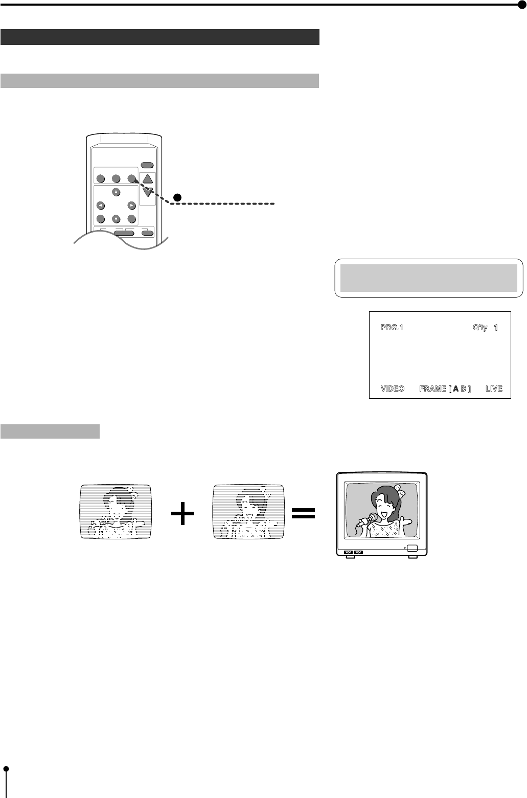
FIELD image FIELD image FRAME image
,A video picture is normally composed of two slightly lower resolution images ( “FIELD” images) to form a single image
(“FRAME” image).
FIELD/FRAME
29
6. Printing Procedures (Basic prints)
1 Selecting input signal
,Select “VIDEO” , “S-VIDEO” or “RGB” according to the input signal.
,The input signal can be set on the menu screen displayed on the monitor or LCD.
,It is not necessary to select the input signal everytime you print unless the input signal is changed.
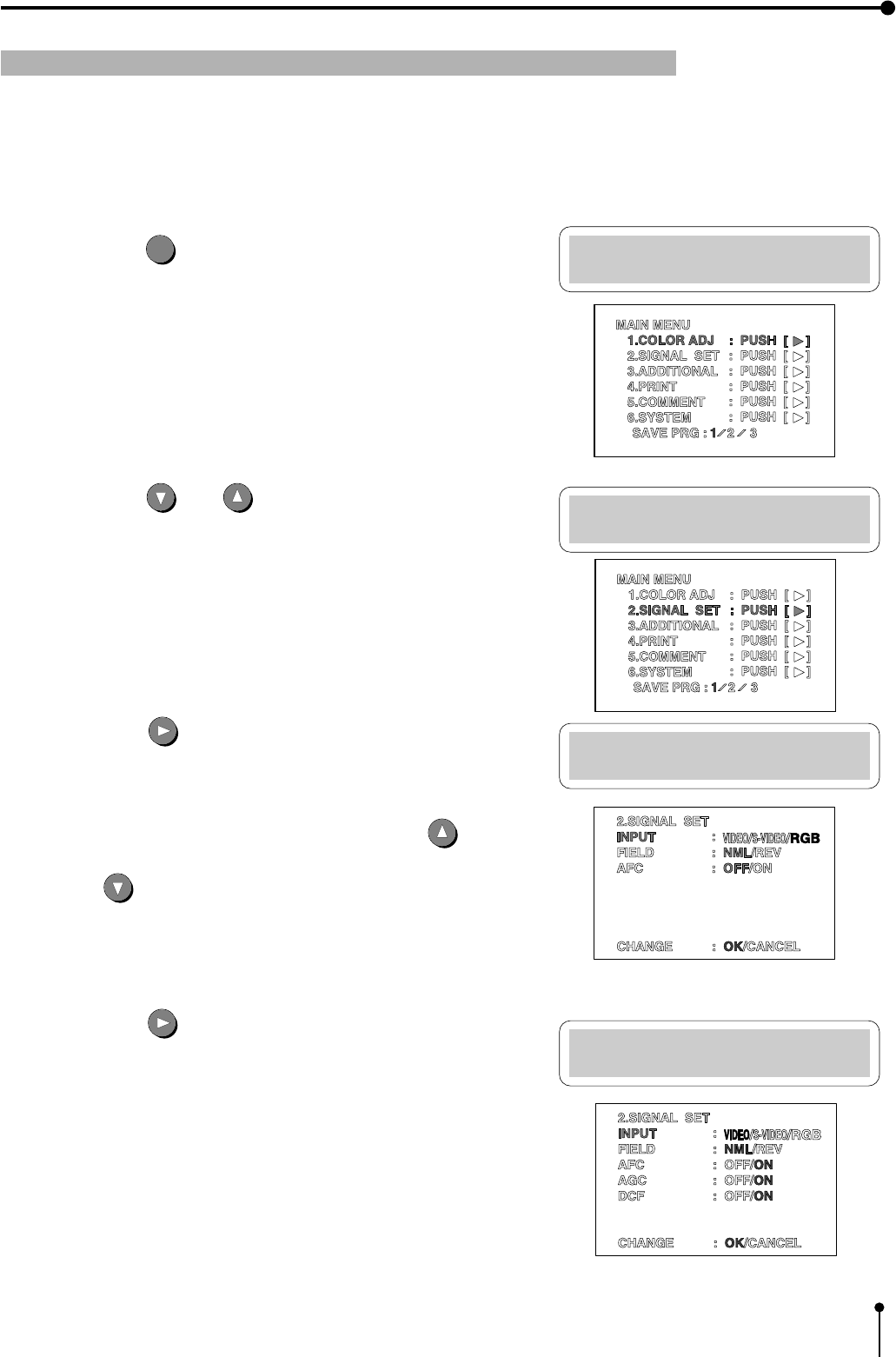
1Press the MENU
MENU
button.
,“MAIN MENU” is displayed.
2Press the DOWN or UP button to select “2. SIGNAL SET
[ ] ]” .
3Press the RIGHT button.
,“2. SIGNAL SET” menu screen is displayed.
,
Normally, “INPUT” is selected when opening the “2. SIGNAL SET [ ] ]”
on step 2. When other item is selected, press the UP or
DOWN button to select “INPUT” .
4Press the RIGHT shift button to select “VIDEO” , “S-VIDEO” or “RGB” .
Main Menu
1.COLOR ADJ :PUSH[>]
Main Menu
2.SIGNAL SET:PUSH[>]
Signal Set Menu
INPUT:RGB
Signal Set Menu
INPUT:Video
30
6. Printing Procedures (Basic prints)
Signal Set Menu
CHANGE : OK
Main Menu
2.SIGNAL SET:PUSH[>]
Main Menu
SAVE PRG: 1
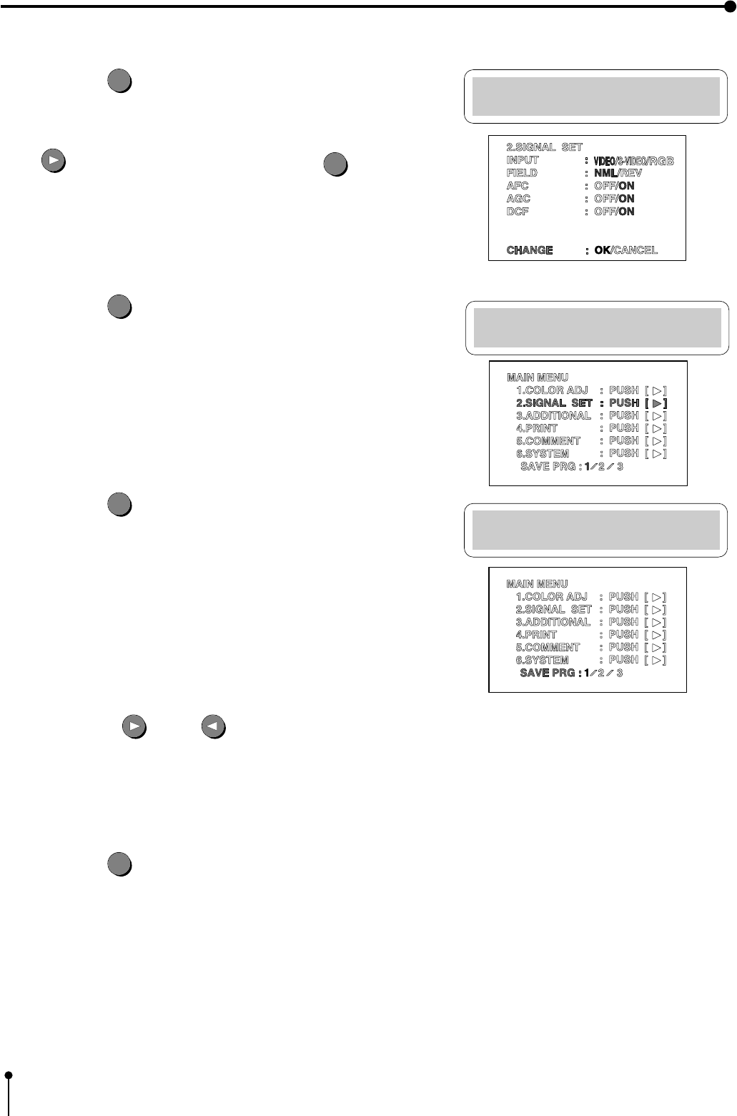
5Press the SET
SET
button .
,“CHANGE : OK” is selected.
,When changing the input signal selected at step 4, press the RIGHT
button to select “CANCEL” . Press the SET
SET
button to
select “INPUT” in “2. SIGNAL SET” again.
6Press the SET
SET
button.
,The MAIN MENU is displayed.
7Press the SET
SET
button.
,“SAVE PRG 1/2/3” is selected.
,This menu is used to store the setting in any one of 3 programs
(1, 2 or 3).
8Press the RIGHT or LEFT button to select the program
number 1, 2 or 3 to store the setting.
,The setting will be overlaid. In case of keeping the stored program, do
not select the program No. in which the setting is stored.
9Press the SET
SET
button.
,The source image (image from the input signal) is displayed.
,The selection of input signal is completed.
31
6. Printing Procedures (Basic prints)
1 Setting print size (S/L)
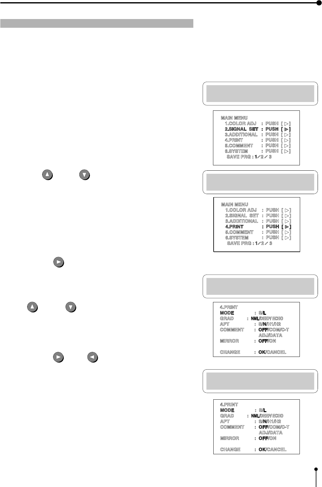
1Press the MENU button.
,“MAIN MENU” is displayed.
Main Menu
2.SIGNAL SET:PUSH[>]
Main Menu
4.PRINT :PUSH[>]
Print Menu
MODE :S
Print Menu
MODE :L
,Set the print size to “S” or “L” according to the ink sheet installed.
,The print size can be set on the menu screen displayed on the monitor or LCD.
,It is not necessary to set the size everytime you print unless the size of the ink sheet is changed.
2Press the UP or DOWN button to select “4. PRINT PUSH [ ] ]”
.
3Press the RIGHT button.
,“Print Menu” is displayed.
,When the power is turned on, “MODE:S/L” is already selected in
“4. PRINT PUSH [ ] ]” at step 2. If other item is selected, press the
UP or DOWN button to select “MODE:S/L” .
4Press the RIGHT or LEFT button to select “S” or “L” in the
“MODE” .
32
6. Printing Procedures (Basic prints)
5Press the SET
SET
button.
,“CHANGE : OK” is selected.
,When changing the size setting selected at step 4 , press the RIGHT
button to select “CANCEL” . Press the SET
SET
button to
select “MODE : S/L” in “4.PRINT” again.
6Press the SET
SET
button.
,The MAIN MENU is displayed.
7Press the SET
SET
button.
,“SAVE PRG 1/2/3” is selected.
,This menu is used to store the setting in any one of 3 programs
(1, 2 or 3).
8Press the RIGHT or LEFT button to select the program number 1, 2 or 3 to store the setting.
,The setting will be overlaid. In case of keeping the stored program, do not select the program number in which the
setting is stored.
9Press the SET
SET
button.
,The source image (image from the input signal) is displayed.
,The setting of print size is completed.
Print Menu
CHANGE : OK
Main Menu
4.PRINT :PUSH[>]
Main Menu
SAVE PRG: 1
33
6. Printing Procedures (Basic prints)
1 MEMORY PAGE
The following image memorization function is available since this unit has 2 frames to memorize images.
When storing one image in the memory:
,In the frame mode, 2 images can be memorized in 2 frames.
Image A Image B
1 frame + 1 frame = 2 frames
,In the field mode, 4 images can be memorized in 2 frames.
Image A Image B Image C Image D
1/2 frame + 1/2 frame + 1/2 frame + 1/2 frame= 2frames
1 Field=1/2 frame
As the image in the field mode is printed in half the resolution level of that in frame mode, the print image will be lower in
resolution.
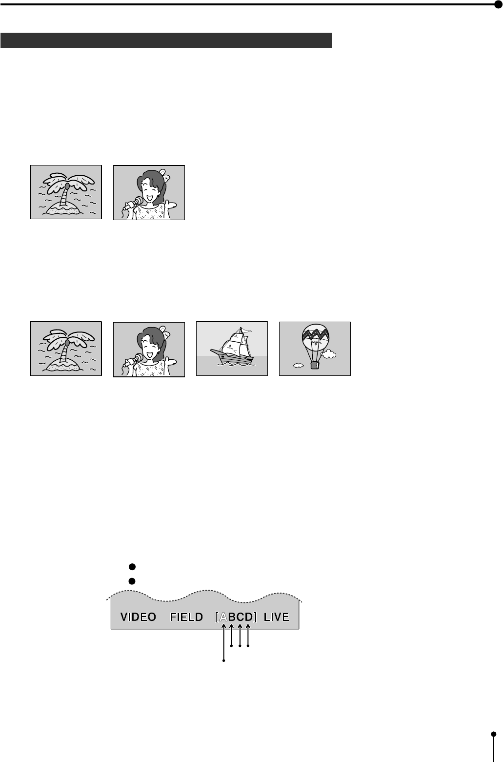
,Each time the “FIELD / FRAME” button is pressed, the number of memory page is switched.
,The memory page is displayed as [ A B ] or [ A B C D ] on the lower part of the monitor screen.
Page being selected
Page the image can be stored in
[A B] is displayed in the FRAME mode.
[A B C D] is displayed in the FIELD mode.
34
6. Printing Procedures (Basic prints)
,The page to store an image can be selected by pressing the MEMORY PAGE button. The page being selected is shown
in green.
,The image will be stored in the selected memory page when pressing the MEMORY button. (when memory page
increment is set to OFF)
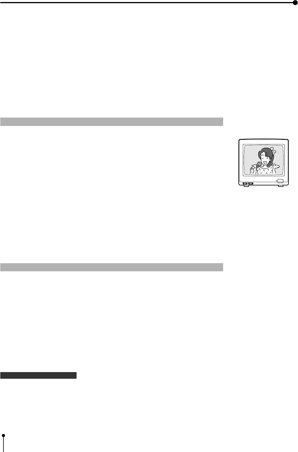
,When pressing the MONITOR button, the image of the memory page being selected is displayed on the monitor.
When the memorized image is displayed, “MEMORY” is displayed on the upper part of the monitor screen. When the
image of the input signal is displayed, “LIVE” is displayed.
The memory image selected with the MEMORY PAGE button is displayed on the monitor.
,An image can be stored in memory even while printing an image. (when print speed mode is set to Normal in memory
page menu.)
1 Storing images in memory / Printing the images
1Display the image to be printed on the screen.
2Press the MEMORY button.
,When images are memorized on one or more memory pages, press the MEMORY
PAGE button on the remote control to select the memory page to be printed.
,The selected page is indicated in green.
,When displaying “MEMORY” on the monitor by pressing the MONITOR button, the
image of the memory page being selected is displayed on the monitor.
3Press the PRINT button.
,The memorized image is printed.
,The memory page under printing is indicated on the monitor screen. The character
showing the memory page under printing goes on and off in [A B] or [A B C D].
Image memorizing with PAGE INC (Page Increment) function
PAGE INC (Page Increment) : When the “automatic memory page turning” function is valid, the image memorizing is done as
follows:
,Each time the MEMORY button is pressed, the images will be memorized in the order of A, B, C, D .
,In case of memorizing an image on a memory page, select the previous page by pressing the MEMORY PAGE button.
Then, press the MEMORY button to memorize the image.
Example : Select page B to memorize an image in page C.
The various functions of this unit are set on the menu screens. Refer to pages 19 - 20 for setting this function.
Refer to page 51, “6.SYSTEM” on system setting menu.
Note
]An image may not be printed correctly when a VCR plays back in special effects playback mode (such as speed search)
during printing. The special effects playback should not be made during printing.
To memorize and print the images of special playback mode, memorize the desired image first. Then, stop the special
playback and start printing. Do not play back image in special playback mode after starting printing.
35
6. Printing Procedures (Basic prints)
2 Continuous printing
The desired number of memorized images can be printed continuously when the desired number is set before printing.
The number of prints can be changed during printing. The continuous printing also can be cancelled by setting the number of
prints to 1 during printing.
1 Setting the number of prints
Press the PRINT Q'TY buttons , to set the number of prints.
,Press button to increase and button to decrease the number.
,The number of prints will be switched in the order of
1 ←→ 2 ←....→ 9 ←→ 10 ←→ 20 ←→ 30 ←→ 40 ←→ 50 ←→ 100 ←→ 200 ←→ C ←→ 1
When "C" is selected, this unit continues printing until the print paper or ink sheet is used up.
1 Cancelling continuous printing
,When cancelling continuous printing:
ACancelling after printing of an image is completed.
Press the PRINT Q'ty buttons , to set the number of prints to 1.
,After the image being printed is printed out correctly, the continuous printing is cancelled.
BCancelling before printing of an image is completed.
Press the STOP button on the remote control.
,The continuous printing is cancelled not completing the print, and the sheet comes out.
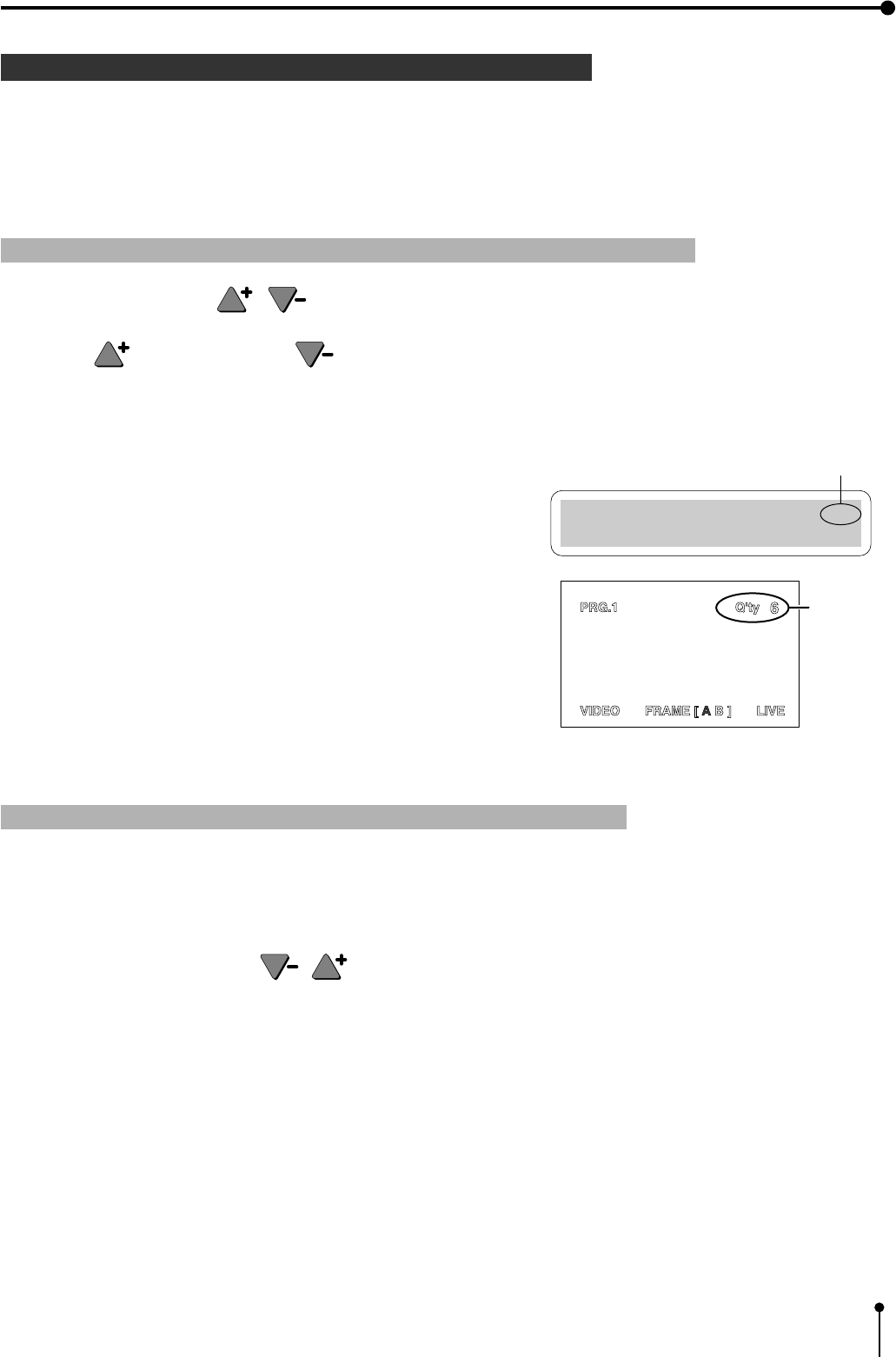
,The set number of prints is displayed on the monitor screen and LCD.
,During continuous printing, whenever one sheet is printed, the set
number is counted down.* The number is displayed on the monitor
screen or LCD.
,After the continuous printing is completed, the set value returns to “1”.
*When “C” is selected, the number is not counted down.
Number
of prints
Normal PRG.1 Q'ty: 6
Page:A FIELD Video
Number of prints

36
6. Printing Procedures (Basic prints)
1 Changing the number of prints during printing
,When changing the number of prints during printing:
1Press the PRINT Q'ty buttons , to set the number of prints to 1.
2After the image being printed is printed out, press the PRINT Q’ty buttons , to change the number of prints.
Note :
0If blackish image is continuously printed, the internal temperature may rise and cause the unit to switch to a stand-by
condition during printing.
An error message “OVER HEAT” is displayed on LCD or monitor screen.
In this case, wait until the error message goes off.
Continuous printing resumes when the temperature drops and error message goes off.
37
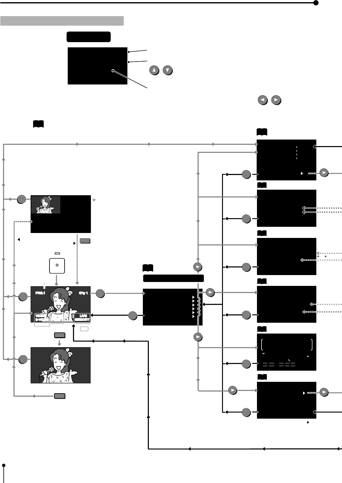
7. Setting the functions
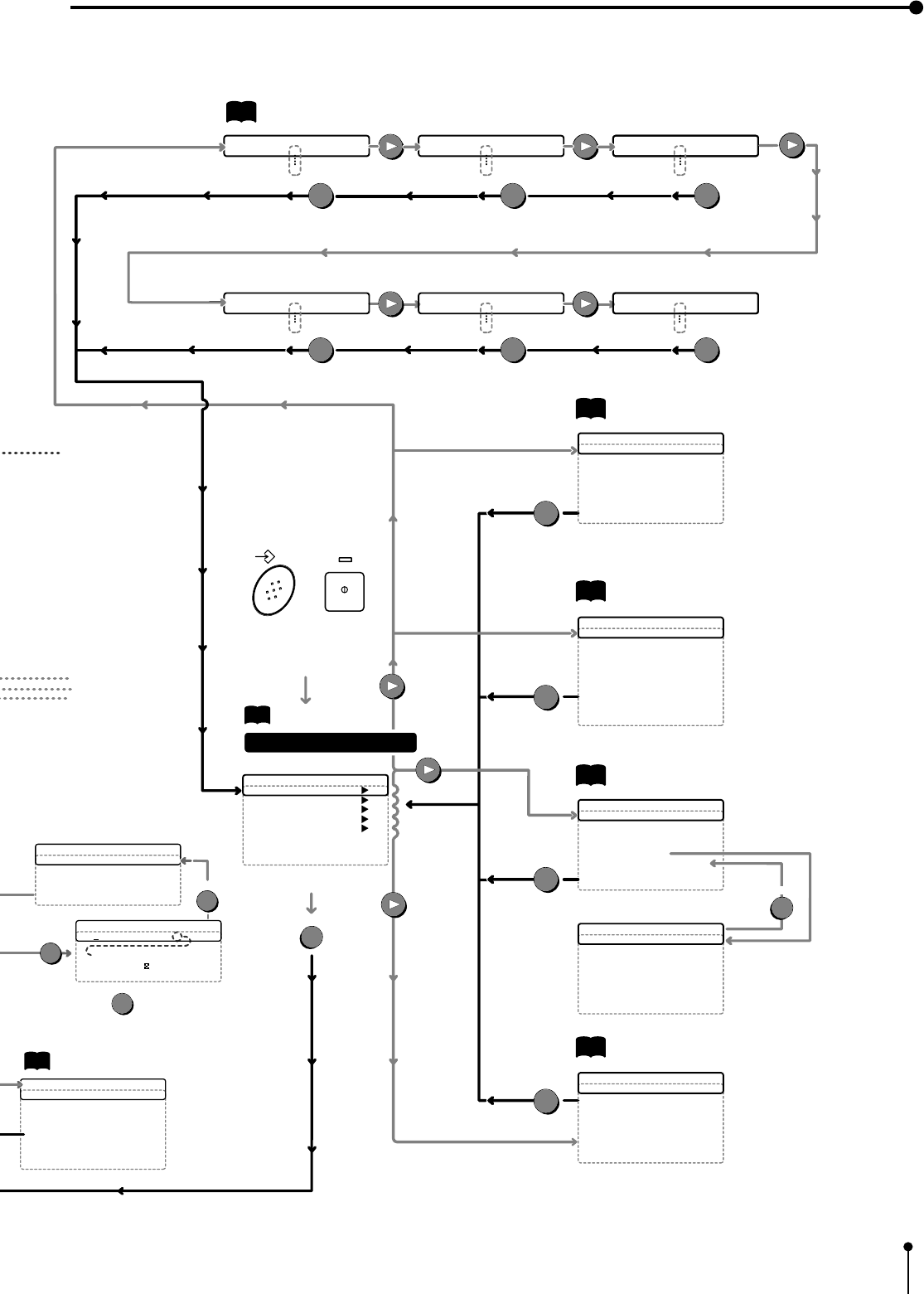
fi
fi
MAIN MENU is used to open the sub menu. Setting the following with the sub menu.
When selecting "SAVE PRG", the setting can be stored.
1. COLOR ADJ .................. Adjust color of printing image
2. SIGNAL SET ................. Selecting the input signal, reverse of odd and even field lines, filter, etc.
3. ADDITIONAL .................. Setting the number of images in a print, strobe print, photo print
4. PRINT............................. Selecting paper size, comment printing method, Adjusting image outline,
Adjusting print image density, mirror print (left/ right inversed)
5. COMMENT ..................... Making a comment
6. SYSTEM......................... Setting print area and printing size, turn the memory page,
switching output of the input signal
SAVE PRG ......................... Storing the above setting in 3 kinds of memories.
Memory SW MENU is used to open the sub menu.
1. TIME ADJ ....................... Setting the date and present time
2. KEY SET ....................... The function of button is invalid, setting the function of memory button
3. SIGNAL ADJ ................. Signal polarity, signal level, synchronized signal timing, Horizontal starting position
Color adjustment of the image
4. PRINT SET.................... Print direction, printing speed, cutting position, Adjusting print image density
5. SYSTEM SET................ Initializing user setting, Baud rate, RS-232C Command type, Response command
Remote busy logic, Inform the number of remaining paper
Main Menu PRG.
1.COLOR ADJ : PUSH [ ]
2.SIGNAL SET : PUSH [ ]
3.ADDITIONAL
: PUSH [ ]
4.PRINT : PUSH [ ]
5.COMMENT : PUSH [ ]
6.SYSTEM : PUSH [ ]
SAVE PRG : 1 / 2 / 3
Memory SW Main Menu
1.TIME ADJ : PUSH [ ]
2.KEY SET : PUSH [ ]
3.SIGNAL ADJ : PUSH [ ]
4.PRINT SET : PUSH [ ]
5.SYSTEM SET : PUSH [ ]
CHANGE : OK CANCEL INIT
38
7. Setting the functions
3.ADDITIONAL
STOROBE : OFF/1/15 sec
MULTI : OFF/ON
MODE :
SAME/DIFF/PHOTO
IMAGES : 2/4/16
SEPARATE : OFF/ON
CHANGE : OK/CANCEL
pis reference page.
2.SIGNAL SET
INPUT
:
VIDEO/S-VIDEO/RGB
FIELD : NML/REV
AFC : OFF/ON
AGC : OFF/ON
DCF : OFF/ON
CHANGE : OK/CANCEL
1.COLOR ADJ
BRT : 0 --------------------------
CONT : 0 --------------------------
R-SUB : 0 --------------------------
B-SUB : 0 --------------------------
CENTER : OFF/ON
ANALOG ADJ : PUSH [ ]
CHANGE : OK CANCEL
3.ADDITIONAL
STROBE : OFF/1/13 sec
MULTI : OFF/ON
MODE :
SAME/DIFF/PHOTO
IMAGES : 2/2s/4/16 CARD /3 4/5 5
SEPARATE : OFF/ON
CHANGE : OK/CANCEL
5.COMMENT
MITSUBISHI COLOR
VCP CP700E
0123456789
ABCDEFGHI
JKLMNOPQRSTUVWXYZ
+ -
/ =( ), . ; :&!?
CAPS SHIFT
INS
DEL CLR
CHANGE : OK/CANCEL
6.SYSTEM
SIZE : W/M/N/USER
USER ADJ : PUSH [ ]
PAGE INC : OFF/ON
LIVE SEL : ANA/DIG
CONVERT : OFF/ON
BUZZER : OFF/ON
CHANGE : OK/CANCEL
SET
MENU
DISPLAY
DISPLAY
SET
SET
SET
SET
SET
SET
p41
p42
p44
p48
2
3 4
Multi-image display
Set conditions display
Source image
p46 Print setting display 1
p48 Making a comment display
System setting display 1
Signal selection display
Image adjustment display
1
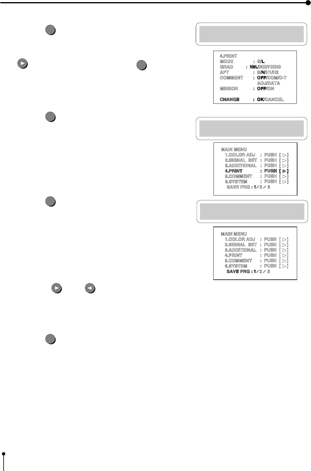
MAIN MENU
1.COLOR ADJ : PUSH [ ]
2.SIGNAL SET : PUSH [ ]
3.ADDITIONAL : PUSH [ ]
4.PRINT : PUSH [ ]
5.COMMENT : PUSH [ ]
6.SYSTEM : PUSH [ ]
SAVE PRG : 1/2/3
This display is indicated only when
Multi-image setting is set.
4.PRINT
MODE : S/L
GRAD :
NML/DEEP/ ECHO
APT : S/N/H1/H2
COMMENT : OFF/COM/C-T
ADJ/DATA
MIRROR : OFF/ON
CHANGE : OK/CANCEL
Monitor display
■ The menu is selected by pressing
.
■ Changing a value, selecting mode, switching
ON or OFF is switched by pressing .
Operation
COLOR
ADJUST
When multi-image setting
is selected.
Not displayed when
selecting RGB
DISPLAY
MAIN menu
Special print setting display
p45
COLOR
ADJUST
COLOR
ADJUST
3
2
3
2
POWER
ON
PRG.1 Q'ty 1
VIDEO FRAME [ A B ] LIVE
S-VIDEO FIELD MEMORY
RGB
shows the selected status .
One of them is indicated.
"USER ADJ : PUSH [ ]
" i
s
indicated only when selecting
"
SIZE : USER".
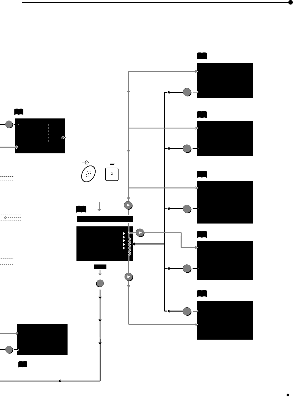
39
7. Setting the functions
MEMORY POWER
+
When pressing the power button while
pressing the MEMORY button, the
following menu is indicated.
1.
TIME ADJ
28-02-99
19:45:00
2.
KEY SETTING
KEY LOCK : OFF/ON
MEM & PRINT : OFF/ON
MEM & STOP : OFF/ON
MEM & MON : OFF/ON
PRINT & CLR : OFF/ON
CLEAR KEY : ONE/ALL
CHANGE : OK/CANCEL
3.
SIGNAL ADJ
IN SYNC : 0.3V / TTL,SOG
OUT SYNC : 0.3V / TTL
SYNC : POSI/NEGA
RGB SOG OUT : OFF/ON
H-START : NML/FRONT
SPCL TIMING : OFF/ON
MON R-SUB : 0
MON B-SUB : 0
CHANGE : OK/CANCEL
4.
PRINT SETTING
PRN DIR : NML/REV
PRN SPEED : NML/FAST
MARGIN CUT : OFF/ON
V POSITION : 0
ECHO GAMMA ADJ
a : ( 64 , 0 )
b : ( 128 , 0 )
c : ( 192 , 0 )
CHANGE : OK/CANCEL
SET
SET
SET
SET
SET
p56
Print setting display 2
p 61
p 59
p 58
System setting display 2
Button function setting display
Day and present time setting display
Signal adjustment display
MEMORY SW MENU
1.
TIME ADJ : PUSH [ ]
2.
KEY SET : PUSH [ ]
3.
SIGNAL ADJ
: PUSH [ ]
4.
PRINT SET : PUSH [ ]
5.
SYSTEM SET : PUSH [ ]
CHANGE : OK / CANCEL / INIT
SET
Memory SW menu
OK
USER SIZE ADJ
H-POSI : 0 ( -10 ~ 10 )
COPY : OFF/W/M/N
TOP : 0 ( -16 ~ 134)
BOTTOM : 0 ( -134 ~ 16)
LEFT : 0 ( -34 ~ 270)
RIGHT : 0 ( -270 ~ 34)
CHANGE : OK/CANCEL
SET
p43
p49 Image size setting display
Analog image adjustment display
Not displayed when selecting RGB or S-video
Not displayed when selecting RGB
"COMMENT" and "MIRROR are not
indicated when selecting
" MODE : PHOTO".
Indicated only when "MULTI : ON"
CARD is indicated when selecting
MULTI : ON and PHOTO
ANALOG ADJ
BRT : 0 --------------------------
CONT : 0 --------------------------
R-SUB : 0 --------------------------
B-SUB : 0 --------------------------
COLOR : 0 --------------------------
CENTER :ON/OFF
CHANGE : OK CANCEL
SET
p11
p 57
5.
SYSTEM SETTING
PRG ALL INIT
: OFF/ON
BAUD RATE
: 1200/2400
/4800/9600
COMMAND TYPE : A/B
RESPONSE : RET/NO
REMOTE BUSY : H/L
REMAINING : OFF/0/...
/5/.../10/
CHANGE : OK/CANCEL
40
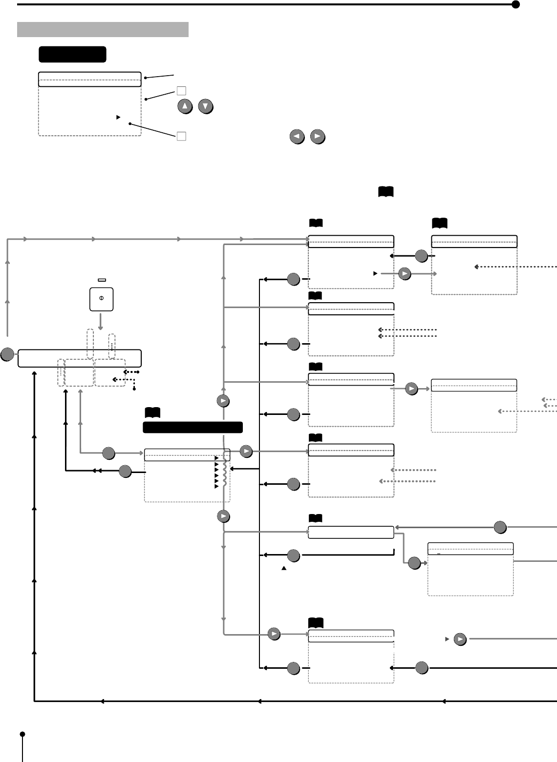
Color Adj Menu
BRT : 0
CONT : 0
R-SUB : 0
B-SUB : 0
CENTER : OFF ON
ANALOG ADJ : PUSH [ ]
CHANGE : OK CANCEL
Comment Menu
CHANGE : OK CANCEL
Fixing the comment
MENU
Analog Adj Menu
BRT : 0
CONT : 0
R-SUB : 0
B-SUB : 0
COLOR : 0
CENTER : OFF ON
CHANGE : OK CANCEL
Print Menu
MODE : S L
GRAD : NORMAL DEEP ECHO
APT : SOFT NORMAL HARD1 HARD2
COMMENT : OFF COM C-T
ADJ DATA
MIRROR : OFF ON
CHANGE : OK CANCEL
SET
SET
SET
SET
SET
SET
SET
SET
p44
p45
p48
p49
p51
p46
p51
p
is reference page.
Set conditions display
Print setting display 1
Comment making display
System setting display 1
Signal selection display
Image adjustment display Analog image adjustment
display
Special print setting display
Main Menu PRG.
1.COLOR ADJ : PUSH [ ]
2.SIGNAL SET
: PUSH [ ]
3.ADDITIONAL
: PUSH [ ]
4.PRINT : PUSH [ ]
5.COMMENT : PUSH [ ]
6.SYSTEM : PUSH [ ]
SAVE PRG : 1 / 2 / 3
Additional Menu
STROBE : OFF 1/13 sec ......... 1hr
MULTI : OFF ON
MODE : SAME DIFFERENT PHOTO
IMAGES : 2 2s 4 16 CARD 3455
SEPARATE : OFF ON
CHANGE : OK CANCEL
Color Adj Menu
BRT : 0
CONT : 0
R-SUB : 0
B-SUB : 0
CENTER : OFF ON
ANALOG ADJ : PUSH [ ]
CHANGE : OK CANCEL
Comment Menu
[MITSUBISHI COLOR ]
[VCP CP 700E ]
Normal PRG.1 Q'ty 1
Page:A FIELD Video
FRAME S-Video
D RGB
3
2
p47
MENU
MENU
P
MAIN MENU
SET
LCD display
The menus in the broken line are indicated by the shift
buttons.
Press the shift buttons to change the value,
select the mode or switch the item.
(The item indicated by switching is shown in light character in this chart.)
Operation
When "MULTI : ON"
Signal Set Menu
INPUT
: Video S-Video RGB
FIELD : NORMAL REVERSE
AFC : OFF ON
AGC : OFF ON
DCF : OFF ON
CHANGE : OK CANCEL
Additonal Menu
STROBE : OFF 1 /13sec ......... 1hr
MULTI : OFF ON
CHANGE : OK CANCEL
COLOR
ADJUST
COMMENT and MIRROR are not
indicated when selecting
"MODE : PHOTO".
Indicated when selecting S-VIDEO
Indicated when selecting RGB
Not indicated when selecting RGB or S-VIDEO
Not indicated when selecting RGB
POWER
ON
CHANGE : OK
System Menu
SIZE : WIDE MIDDLE NARROW USER PUSH [ ]
PAGE INC : OFF ON
LIVE SEL : ANALOG DIGITAL
CONVERT : OFF ON
BUZZER : OFF ON
CHANGE : OK CANCEL
7. Setting the functions
41
Menu System Display
H-POSI : 0
COPY : OFF WIDE MIDDLE NARROW
TOP : 0
BOTTOM : 0
LEFT : 0
RIGHT : 0
CHANGE : OK CANCEL
p52
Image size setting display
Comment Menu
[MITSUBISHI COLOR] M
NOPQRSTUVWXYZ
+ -
/=
(),.;:&!?
0123456789
ABCDEFGHIJKLM
Comment Menu
Caps : ON OFF
SHIFT : OFF ON
INS : PUSH [SET]
DEL : PUSH [SET]
CLR : PUSH [SET]
MENU
MENU
{Selecting characters.
Fix the character with the
SET button and move to the next
position.
}Editing
capital/small letter
Inserting a space
deleting a character,
clearing the comment
SET
Indicated when selecting
"MULTI : ON"
CARD is indicated only when
selecting "MULTI : ON" and
"PHOTO".
Not indicated when
selecting RGB
Time Adj Menu
SECOND : 0
59
Time Adj Menu
MINUTE : 0
59
MEMORY POWER
+
When pressing the power button
while pressing the MEMORY button,
the following menu is indicated.
SET
SET
SET
SET
Print setting display 2
p 64
p 62
p 61
p 60
System setting display 2
Button function setting display
Date setting display
Signal adjustment display
Time Adj Menu
YEAR : 00
99
Time Adj Menu
MONTH : 1
12
Time Adj Menu
DATE 1
31
Time Adj Menu
HOUR
0
24
SET SET SET
SET SET SET
Key Setting Menu
KEY LOCK : OFF ON
MEM & PRINT : OFF ON
MEM & STOP : OFF ON
MEM & MON : OFF ON
PRINT & CLR : OFF ON
CLEAR KEY : ONE ALL
CHANGE : OK CANCEL
Signal Adj Menu
IN SYNC : 0.3V TTL,SOG
OUT SYNC : 0.3V TTL
SYNC : POSI NEGA
RGB SOG OUT : OFF ON
H-START : NORMAL FRONT
SPCL TIMING : OFF ON
MON R-SUB : 0
MON B-SUB : 0
CHANGE : OK CANCEL
Print Set Menu
PRN DIR : NORMAL REVERSE
PRN SPEED : NORMAL FAST
MARGIN CUT : OFF ON
V POSITION : 0
ECHO GAMMA ADJ
CHANGE : OK CANCEL
Print Set Menu
ECHO GAMMA a : X = 64
a : Y = 0
b : X = 128
b : Y = 0
c : X = 192
c : Y = 0
System Set Menu
PRG ALL INIT
: OFF ON
BAUD RATE
: 1200 2400 4800 9600
COMMAND TYPE : A B
RESPONSE : RETURN NO
REMOTE BUSY : H L
CHANGE : OK CANCEL
SET
p59
Memory SW menu
SET
OK
p11
Memory SW Main Menu
1.TIME ADJ : PUSH [ ]
2.KEY SET : PUSH [ ]
3.SIGNAL ADJ : PUSH [ ]
4.PRINT SET : PUSH [ ]
5.SYSTEM SET : PUSH [ ]
CHANGE : OK CANCEL INIT
7. Setting the functions
42
7. Setting the functions
1 Displaying menu screen
,All functions are operated with the remote control.
1Main menu – sub menu display
,Press the MENU
MENU
button to display Main menu.
2MEMORY SW MENU – sub menu display
,Press the POWER button while pressing MEMORY button to display MEMORY SW menu.
,Make sure to turn the POWER OFF before the above operation.
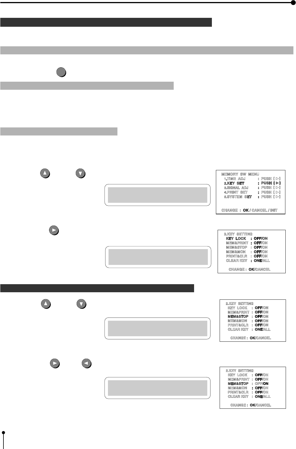
1 Displaying the sub menu
,Select the sub menu for each function setting to display from MEMORY SW MENU or MAIN MENU.
1Press the UP or DOWN shift button to select the menu.
2Press the RIGHT shift button to display the sub menu of the item selected.
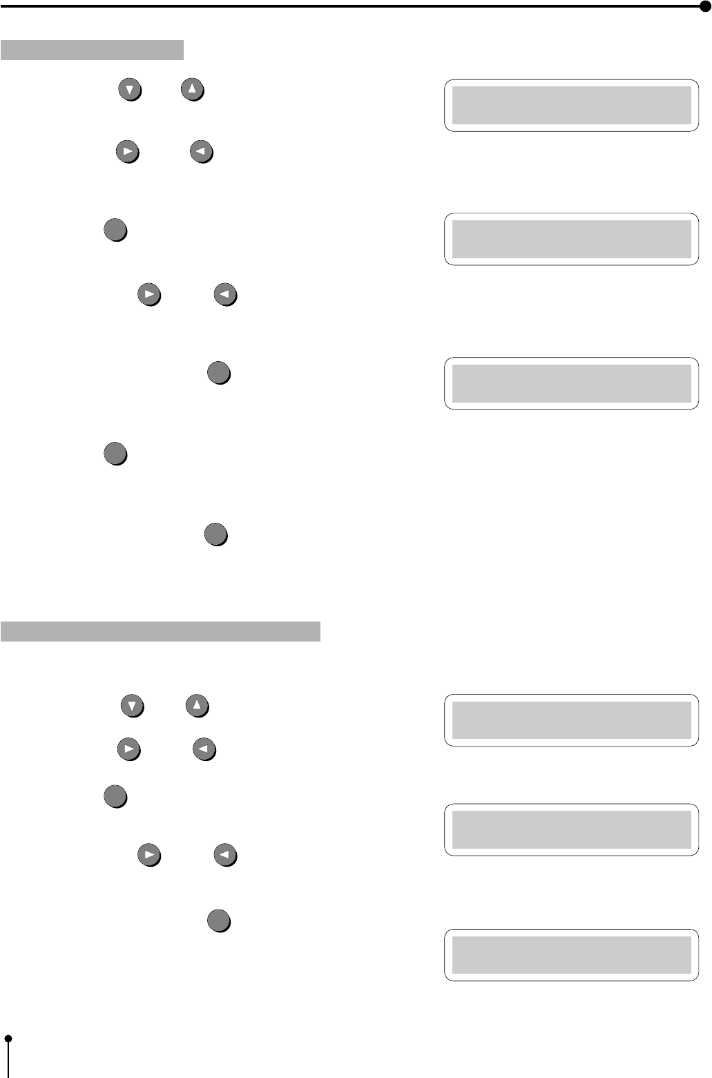
1Procedure for selecting and setting the menu
1 Press the UP or DOWN shift button to select the menu.
2 Press the RIGHT or LEFT shift button to select the item or change the value.
Memory SW Main Menu
2.KEY SET :PUSH[>]
Key Setting Menu
KEY LOCK :OFF
Key Setting Menu
MEM & STOP :OFF
Key Setting Menu
MEM & STOP :ON
43
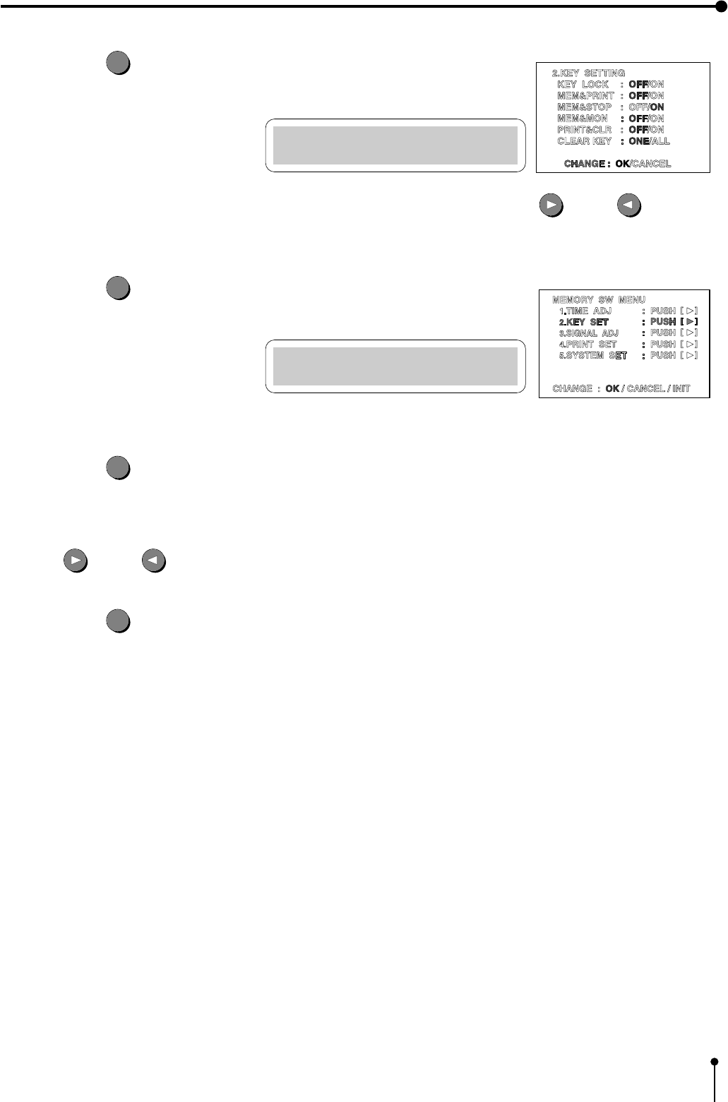
7. Setting the functions
3Press the SET
SET
button.
,“CHANGE : OK/CANCEL” is selected.
,Select "OK" to close the menu. Select "CANCEL" to cancel the setting again by the RIGHT or LEFT button.
4Press the SET
SET
button.
,The function is set and the Main menu
display or Memory SW menu is shown.
5Press the SET
SET
button.
,In the Main menu, “SAVE PRG 1/2/3” is selected.
Store the setting of function on the sub menu 1-6 to program 1.2 and 3. ( Refer to “SAVE PRG” .)
,In the Memory SW menu, "CHANGE : OK/ CANCEL" is selected. When closing the menu, select “OK” by pressing the
RIGHT or LEFT button.
6Press the SET
SET
button.
,The function is set and the source image is shown.
Key Setting Menu
CHANGE :OK
Memory SW Main Menu
2.KEY SET :PUSH[>]
44
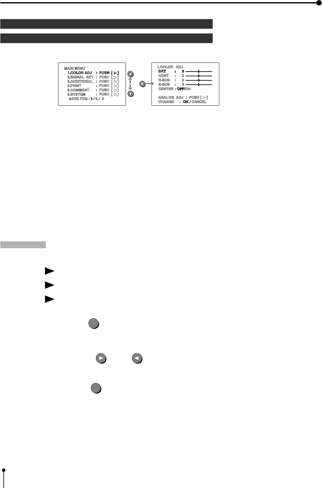
7. Setting the functions (Main menu)
Function
1 MAIN MENU
Open the sub-menu from Memory menu.
SAVE PRG
This menu is shown in the lowest position on the “MAIN MENU” .
Function Storing the setting value on the menu 1-6.
Store the setting of function on the sub menu 1-6 to program 1,2 and 3.
Operation The function is set and then MAIN MENU is displayed.
1. Press the SET
SET
button.
• “SAVE PRG” is displayed on the LCD display indicated in blue.
2. Press the RIGHT or LEFT button to select the memory bank number 1, 2 or 3.
3. Press the SET
SET
button to store the setting to the selected program number.
,The set conditions display and the source image are displayed.
,Program is overlaid, recommend that the previous program number is not selected in step 2.
,
Press the program button to select the memory 1,2, or 3 . The display according to each setting is displayed.
The setting cannot be changed during printing.
,The image can be printed according to the selected memory program.
1 Items and setting displayed are shown below.
1. COLOR ADJ .......... Adjust color of printing image
2. SIGNAL SET .......... Selecting the input signal, reverse of odd and even field lines, filter,etc.
3. ADDITIONAL .......... Setting the number of images in a print. strobe print, photo print
4. PRINT.......................Selecting comment printing method, Adjusting image outline, Adjusting print image density
mirror print (left/ right inversed)
5. COMMENT ............. Making a comment
6. SYSTEM ................. Setting print area and print size, turn the memory page, switching output of the input signal
SAVE PRG .................. Storing the above setting in 3 kind of memories.
e.g. Monitor display 1. COLOR ADJ → B R T
45
7. Setting the functions (Main menu)
1COLOR ADJ Adjusting the color of the image
,With this menu, the color of the source image and memorized image can be adjusted.
,This menu is also displayed by pressing color ADJUST
COLOR
ADJUST button.
BRT (Bright )
Function Adjust the brightness of printing image.
CONT (Contrast )
Function Adjust the contrast of printing image
R-SUB ( Red-subcontrast)
Funciton Adjust the red-subcontrast of printing image
B-SUB ( Blue-subcontrast)
Function Adjust the blue-subcontrast of printing image
,The each function and setting area is as follows.
display adjusting - 64 adjusting area + 63
B R T Brightness Darker ............................. Brighter
display adjusting - 32 adjusting area + 31
CONT Contrast Less contrast ....................... More contrast
R-SUB Red-subcontrast Add cyan ........................... Add red
B-SUB Blue-subcontrast Add yellow ......................... Add blue
CENTER
Function Each function setting value is initialized with the “COLOR ADJ” .
When CENTER is set to “ON” , the setting value of BRT, CONT, R-SUB and
B-SUB is reset to “0”.
ANALOG ADJ (Analog Adjust )
Funciton Image adjustment menu of analog input signal is displayed.
When pressing RIGHT button , “7.ANALOG ADJ” menu is displayed.
46
7. Setting the functions (Main menu)
ANALOG ADJ The adjustment image of analog input signal display
,This menu is used to adjust the image of analog input signal display before storing in the memory.
,This menu is opened when pressing RIGHT button on “ANALOG ADJ : PUSH [ ] ]” .
,When selecting RGB analog signal, “COLOR” “TINT” is not adjusted and displayed.
BRT (Bright )
Function Adjust the brightness of printing image.
CONT (Contrast )
Function Adjust the contrast of printing image.
R-SUB (Red-subcontrast)
Function Adjust the red-subcontrast of printing image.
B-SUB (Blue-subcontrast)
Function Adjust the blue-subcontrast of printing image.
COLOR
Function Adjust the color of printing image
,The each function and setting area is as follows.
Item Adjustment -32 Adjusting area +31
B R T Brightness Darker ............................. Brighter
CONT Contrast Less contrast ....................... More contrast
R-SUB Red-subcontrast Add cyan ........................... Add red
B-SUB Blue-subcontrast Add yellow ......................... Add blue
COLOR Color Light .............................. Deep
• When selecting the RGB signal, COLOR is not shown on the monitor display.
CENTER
Function The setting value of “COLOR ADJ” is initialized.
When this function is set to “ON” , the setting value of BRT, CONT, R-SUB , B-SUB, COLOR is reset to 0.
,When pressing the SET
SET
button after selecting “OK” on the lower position “CHANGE : OK/CANCEL” ,
“1.COLOR ADJ” menu is displayed.
47
7. Setting the functions (Main menu)
2 SIGNAL SET Signal selecting menu
INPUT
Function Select the signal from inputting signal on the rear panel.
VIDEO .......... Signal from VIDEO input terminal
S -VIDEO ..... Signal from S-VIDEO input terminal
RGB ............. Signal from RGB input terminal
FIELD
Function The odd even field lines will be reversed depending on the input interlaced signal.
Printing image is not clear so that the odd and even field lines may be reversed depending on the input
interlaced signal. In this case, FIELD is set to “REV” .
The image status cannot be checked on the monitor display.
NML (Normal) ....Not reversed
REV( Reverse ) ..Reversed the field lines.
AFC
Function Automatic frequency control
This function is to automatically correct the image of a weak signal or in VCR special playback . If the
image is not printed correctly because of a weak TV signal, set the AFC function to “ON”.
,The image distortion on the top may occur when the VCR image is input in pause, field-by-field
playback, or FF playback mode. In this case, AFC function is set to “OFF” .
ON................ AFC available
OFF .............. AFC invalid
{This function menu is not displayed and invalid when selecting “FRONT” on
“3 .SIGNAL ADJ → H-START : NML/FRONT” in MEMORY SW menu.
AGC
Function Automatic gain control (Making the image brighter and stressing the contrast.)
This function is to automatically adjust a dark picture in brightness and prints with sharp contrast. Peak
level of an input signal is detected and signals width is standardized to the appropriate value.
ON................ AGC is available
OFF .............. AGC is invalid
{This function is not displayed when selecting RGB signal.
DCF
Function Select whether separating the composite video signal or not.
When inputting the monochrome signal, this function is set to OFF.
This function is for high quality of monochrome image so that input signal is not though DCF circuit.
When inputting the color signal, this function is set to “ON” . Input signal is through DCF circuit and
the composite video signal is separated.
ON................ when inputting color signal
OFF .............. when inputting monochrome signal
{This function is invalid in RGB or S-VIDEO input signal.
Note: When “DCF” is set to “OFF”, the letter may not be colored on the monitor display.
48
7. Setting the functions (Main menu)
3ADDITIONAL Special print setting
STROBE
Function This function is to repeat storing the image in the memory according to selected the time interval.
When MULTI is set to “ON” , the image is stored in order of image number .
When MULTI is set to “OFF” , every one image is stored in the memory.
• The image is stored in the memory every time as shown below.
,1/13 sec → 1/5 sec → 1/2.5 sec → 1 sec → 2 sec → 5 sec → 10 sec → 30 sec ............ every second
,1 min → 2 min → 5min → 10min → 30 min ..................................................................... every minutes
,1hr ..........................................................................................................................................every hour
,Pressing the LEFT button to select the interval.
,The image is automatically printed after storing the image in the memory when “MEM&PRINT” function
is set to “ON” on “MEMORY SW MENU” → “KEY SETTING” menu.
Note: The monitor display may not be correctly shown when setting the time interval to lower value.
MULTI
Function Switching the multi-image print
ON................ Multi-image prints are available
OFF .............. Multi-image prints are not available
Set the number of images (2,2s,4,16 image) in a print.
Set the number of images in a print and the size with MULTI, MODE, IMAGES, and SEPARATE menus.
Refer to pages 65-80 for multi-image print.
MODE
Function Setting the print mode
SAME ......................... Print the image of the same scenes in a print.
DIFF ( Different ) ...... Print the image of the different scenes in a print.
PHOTO ..................... Portrait-like print
• When “MULTI” is set to “ON”, this function is displayed.
IMAGES
Function Selecting the number of image
“IMAGES” menu is changed depending on selecting the “MODE” function.
• When “MULTI” is set to “ON” , this function is displayed.
When selecting “SAME” or “DIFF” in the “MODE” function
2 ..............2-images in a print (When printing on a L size paper, the image can be printed fully in width.
But the top and bottom of printed image will be lacked.)
2s ............2-images in a print (When printing on a L size paper, the image can be printed without lack.
But each of printed image size is reduced.)
4 ..............4-images in a print
16 ............16-images in a print
When selecting “PHOTO” in the “MODE” menu
CARD .....16-multi images in a print (1.5 x 2.0cm size image)
3*4 ..........4-multi images in a print (3.0 x 4.0cm size image)
5*5 ..........2-multi images in a print (5.0 x 5.0cm size image)
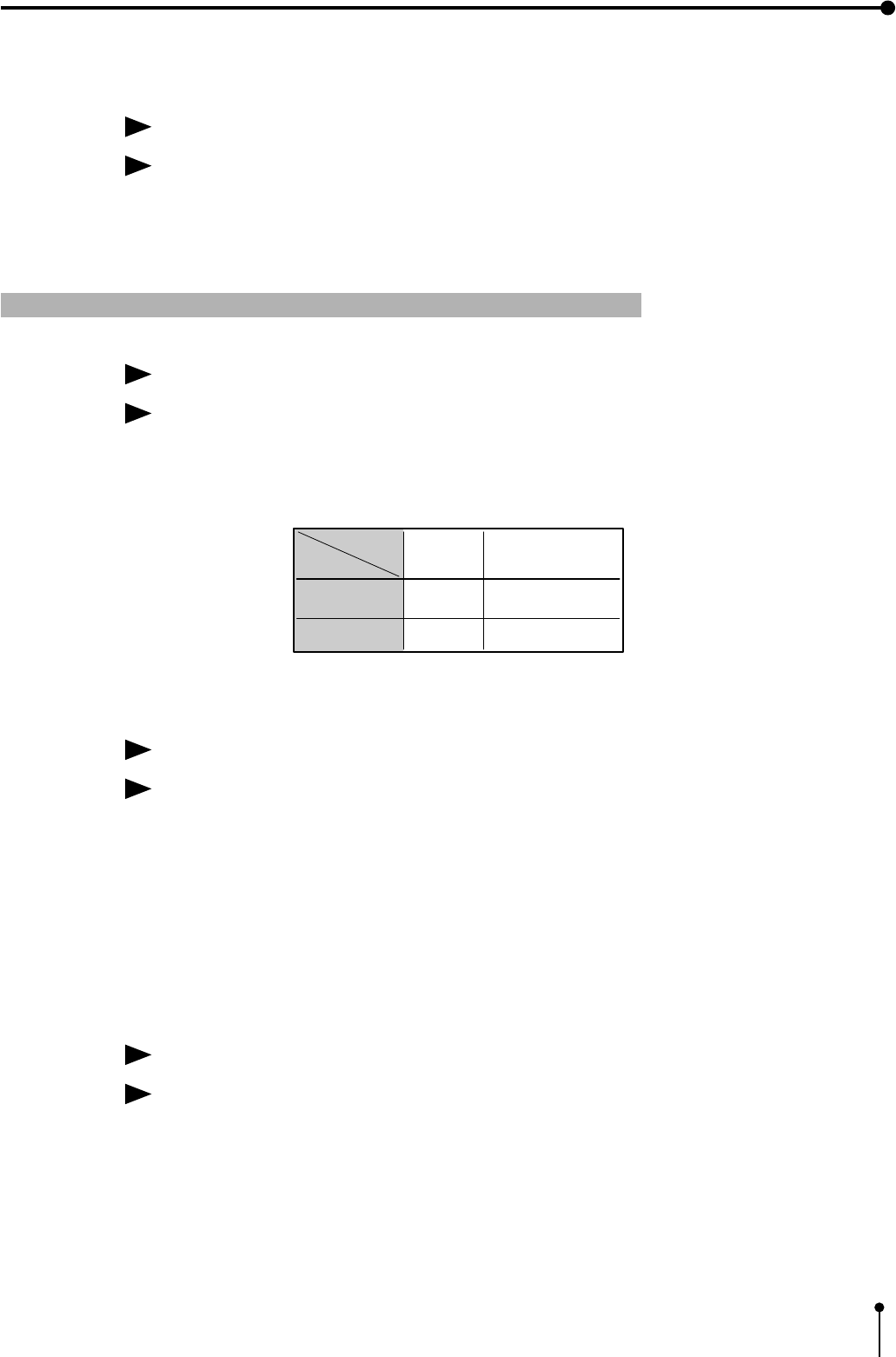
49
7. Setting the functions (Main menu)
SEPARATE
Function Switching the white frame
Separate the each image in multi-image print with white frame
ON................ White frame print
OFF .............. Normal print
• When “MULTI” is set to “ON”, this function is displayed.
4PRINT Print setting 1
MODE
Function Selecting the paper size
Selecting the paper size depending on the installed the ink sheet.
S................... S-size ink-sheet ( model: PK700S)
L ................... L-size ink-sheet ( model: PK700L)
• When installing L-size ink sheet or monochrome ink sheet and selecting “S” , the image can be
printed on S-size. Also the number of prints is as follows.
• When S size ink sheet is set, S-size printing is made even if “L” is selected in print mode.
GRAD (Gradation )
Function Change the gamma curve of the image
Selecting the gamma curve from 3 types
NML ............. Normal
DEEP ........... Deep
ECHO........... The gamma curve is set according to medical equipment.
,If changing the setting value of gamma in ECHO, the value is able to change in “ECHO GAMMA
ADJ” on “MEMORY SW MENU” → “PRINT SETTING” menu.
The setting value in the “ECHO GAMMA ADJ” on the print setting menu is applied to “ECHO” .
Refer to page 63.
APT
Function Adjusting image outline.
This function is to control aperture and to reinforce or soften the contour.
SOFT [ S ] ............. Soften the contour
NML [ N ] ............. Do not perform APT
HARD [ H1 ] ............. Reinforce the contour
HARD [ H2 ] ............. More reinforce the contour
S
S
L
Print
mode
S size print
(200 sheet)
S size print
(125 sheet) L size print
(125 sheet)
Ink
sheet
S size print
(200 sheet)
L
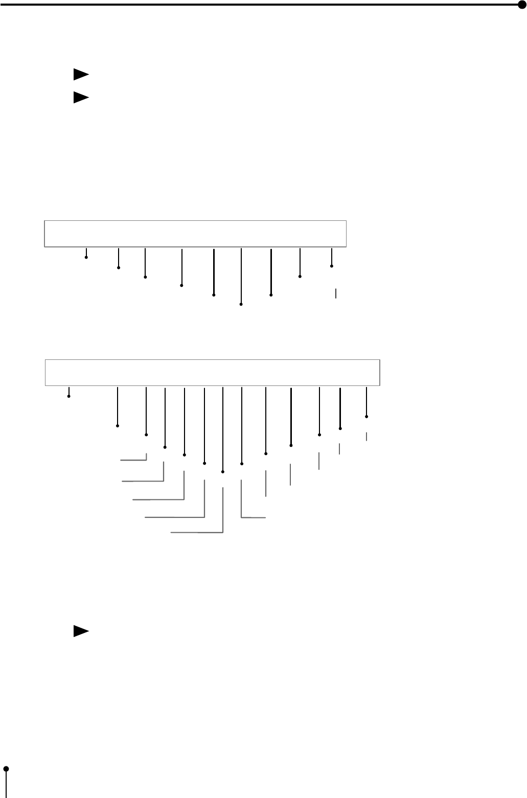
50
7. Setting the functions (Main menu)
COMMENT
Function Selecting the comment
Selecting the comment on printing from 4 types.
OFF ........Comment is not printed.
COM .......Printing the made comment
C-T ..........Printing the made comment and the time and date when the image is stored in memory. The
day and time is overlaid on comment. In this case, all the made comment may not be printed.)
ADJ .........Printing the setting value in the “1.COLOR ADJ” menu.
DATA .......Printing the number of prints, the time of current flowing, field line, filter or image size etc..
, When selecting “ADJ” , the following information is printed.
, When selecting “DATA” , the following information is printed.
, When selecting “ON” in “3. ADDITIONAL MULTI” function and “2” , “2s” , “4” or “16” in
“IMAGE” function, “ADJ” and “DATA” of the last memory image is printed.
MIRROR
Function Selecting mirror (left/right inversed) prints
ON................ Mirror print (The left/light inversed image can be printed.)
OFF .............. Normal print
ADJ +10 ; -11 ; +12 ; - 13 ; +14 ; -15 ; +15 ; -17 ; +18
BRT CONT R-SUB B-SUB ANALOG
BRT ANALOG
CONT
ANALOG
R-SUB
ANALOG
B-SUB
ANALOG
COLOR
When selecting RGB signal, the setting
is not printed.
0 : OFF
1 : ON
0 : Normal
1 : Reverse
0 : Normal
1 : Deep 2 :Echo
-10 ~ +10
-16 ~ +134
-134 ~ +16
-34 ~ +270
-270 ~ +34
0 : OFF
1 : ON
0 : OFF
1 : ON 0 : Soft 1 : Normal 2 : Hard 1 3 : Hard 2
015342 000666 1 0 1 0 2 1 -10 -12 -10 5 -100
( hr. )
(SIGNAL SET MENU )
FIELD
AFC AGC DCFGRADAPT H-POSI TOP BOTTOM
LEFT RIGHT
Total number of prints
Current flowing time
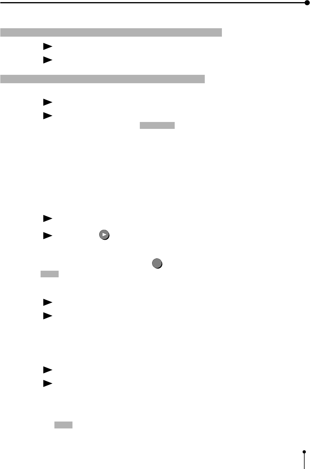
51
7. Setting the functions (Main menu)
5COMMENT Making a comment
Function Making a comment on print
Refer to pages 53-58 for details.
6SYSTEM System setting 1
SIZE
Function Selecting a print area of printing image
Selecting the print size and user print size setting
printing size
Picture element (S size) ( L size)
W1216 X 600 dot 100 X 75 mm 130 X 98 mm
M1148 X 568 dot 94 X 70 mm 123 X 92 mm
N1104 X 544 dot 92 X 69 mm 120 X 90 mm
USER user can set print size
• The image is not correctly printed depending on printing size.
USER ADJ (User Adjustment )
Function This menu is to display USER SIZE ADJ menu.
Press the RIGHT shift button to display USER SIZE ADJ menu .
“CHANGE : OK/CANCEL” is displayed on the lower position.
When selecting “OK” and pressing SET
SET
button, SYSTEM menu is displayed.
Note: When “H-POSI” is shifted to the minus direction at W (WIDE), the monitor screen may get darker.
PAGE INC ( Page Increment)
Function Turn the memory page automatically.
Each time the MEMORY button is pressed, the memory page is turned automatically and the image is
stored in the memory on its page.
ON................ This function is available.
OFF .............. This function is not available.
LIVE SEL ( Live Select )
Function Switching the monitor display of input signal.
This is a function to select whether the image inputted is displayed as it is or the image adjusted its
image and quality by the unit is displayed.
ANA ( Analog ) .........The image inputted is displayed as it is.
DIG ( Digital ) ..........The image adjusted its image and quality is displayed.
Note: • If the characters of character generator is displayed on the monitor screen by setting “DISPLAY”
to ON, the source image is displayed even if “ANA” is selected.
• When set to “ANA” , the 75Ω external terminal is necessary. (e.g. monitor etc.)
[The 75Ω impedance switch on the rear panel is invalid.]
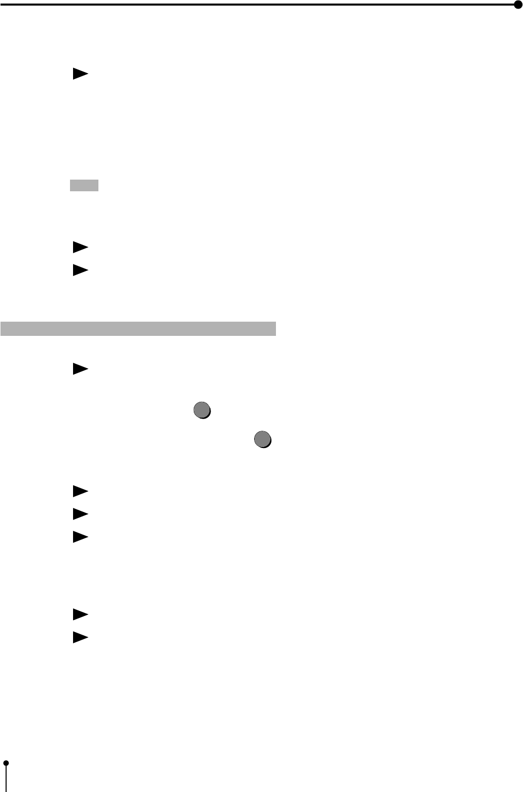
52
7. Setting the functions (Main menu)
CONVERT
Function This function is to output the selected input signal in the “INPUT SEL” function on “2. SIGNAL SET”
menu to the VIDEO/RGB/S-VIDEO output terminal
ON ..........Output the selected input signal to the VIDEO/RGB/S-VIDEO
output terminal
OFF ........Output the signal from the input terminal to the same names
as the input terminal .
Note: When the selected signal is remarkably different from the standard signal in timing, the signal
may not be converted correctly at output.
BUZZER
Function Sounds the buzzer
The buzzer sounds when one of the control buttons is pressed, so that the setting can be checked.
ON ..........Sounds the buzzer
OFF ........Does not sound the buzzer
1 USER SIZE ADJ Setting the image size
The printing area can be changed and stored in memory as a user setting.
When selecting “USER ADJ” on the “6.SYSTEM” menu. Press the RIGHT shift button, USER SIZE
ADJ menu is displayed.
When pressing the SET
SET
button after setting, “CHANGE : OK/CANCEL” is selected.
• When selecting “OK” and pressing the SET
SET
button, SYSTEM menu is displayed.
H-POSI
Function Change the horizontal start position of input signal.
Move the image by changing the horizontal position setting area -10 to +10.
When special setting is set to “ON” in Memory SW menu, the setting area of H-POSI is - 65 to +10.
• As the value is decreasing to the minus limit, the switching between memorized image and source
image may be impossible during printing.
COPY
Function Copy “SIZE” in the “6.SYSTEM” menu.
Copy an image size set at W, M, N in the “6.SYSTEM” menu.
The selected value is displayed from TOP, BOTTOM, LEFT and RIGHT.
The value is the basis of change.
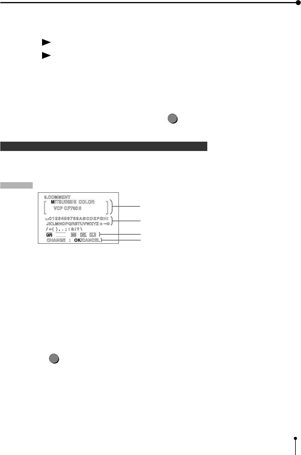
53
7. Setting the functions (Making a comment)
TOP/BOTTOM/LEFT/RIGHT
Function Setting the print area
By adjusting print area, the image size to be printed can be limited. Printing area adjustment can be
operated with the setting menu on the screen.
TOP ............. Top adjustment (setting area -16 to +134 )
BOTTOM...... Bottom adjustment (setting area -134 to +16)
LEFT ............ Left adjustment (setting area -34 to +270)
RIGHT ......... Right adjustment (setting area -270 to +34)
, Select “OK” on “CHANGE : OK/CANCEL” and press the SET
SET
button, then, “6.SYSTEM” menu is displayed.
1 Making a comment
Select the making a comment menu “COMMENT”.
This functions are operated with the remote control using the menus displayed on the monitor screen.
Explanation
, Listed below are the four comment displays.
A ) Comment display block ..................... Inputted letter is displayed , Setting the input position
B ) Character block ................................. Inputting the character block, Selecting the letter from character block
C ) Editing or selecting block .................. Caps letter, small caps letter selecting, selecting the special letter mode,
Insert the space, delete a letter or clear the comment
D ) CHANGE : OK/CANCEL ................. A block to fix the set comment :
When fixing the comment, select “OK”.
When the comment is not set and inputting or changing a letter or changing,
select “CANCEL”.
,Press the MENU
MENU
button to select the desired block.
,The desired function is set on the block.
SHIFT
A)
B)
C)
D)
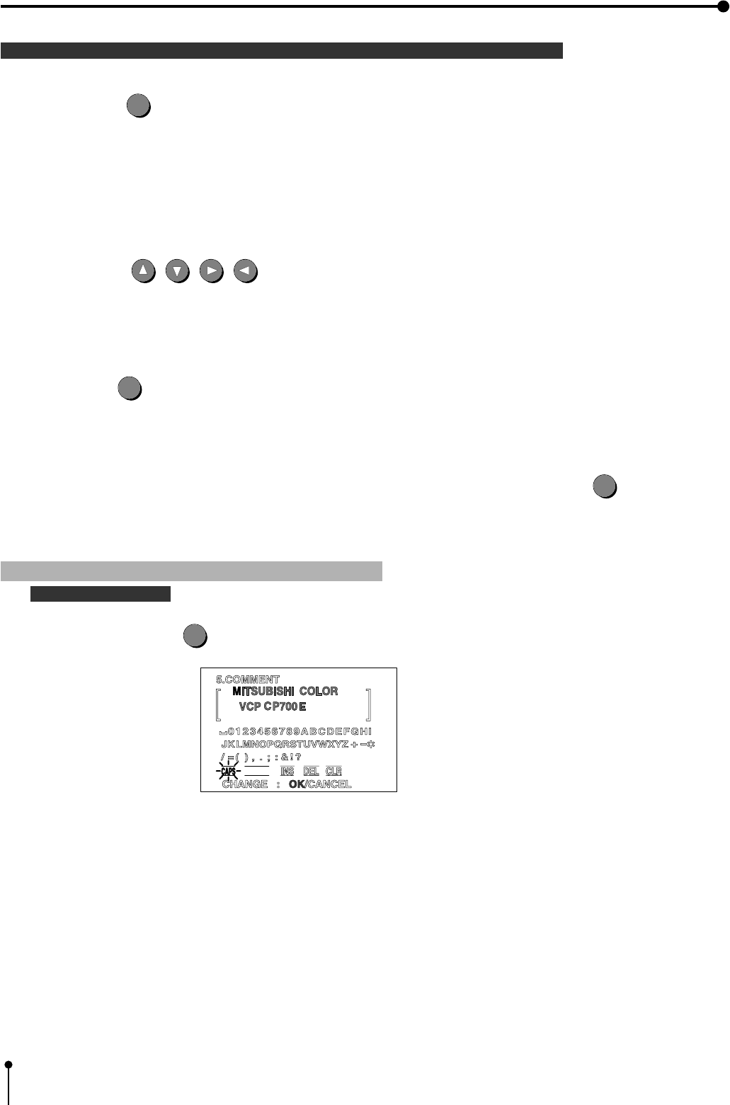
54
7. Setting the functions (Making a comment)
1 Remote control function on the comment display
Menu button
MENU
........ Selecting 4 blocks on the comment menu
A ) Comment display block
B ) Character block
C ) Editing mode selecting mode
D ) CHANGE : OK/CANCEL
, When pressing “MENU” button, the blocks will be switched in order of A → B → C → D → A...
Shift button , , , ..... Use these buttons by the following operation
a) Comment display block .............. Selecting the position to insert the comment
b) Character block .......................... Selecting the letter on the character block
c) Editor selecting mode block ....... Inputting the alphabet, Inputting mark and special letter, Insert a space,
delete a letter, clear the whole comment
SET button
SET
.....Use these button by the following operation
, Insert the letter on the character code
, Switching the capital letter and small letter in the editor selecting mode
, Switching the mark and special letters on the character mode.
,When selecting “OK” on “CHANGE : OK/CANCEL” and press the SET
SET
, “MAIN MENU”
menu display is shown.
1 Menu display
Selecting block
,Each time the MENU
MENU
button is pressed , the selecting block is switched.
A) The selected block is displayed in green. The letter being selected is turned on or off in red.
B) The selected character block is displayed in green. The letter being selected is turned on or off in red.
C) The selected command in the editing selection mode block is turned on or off .
SHIFT
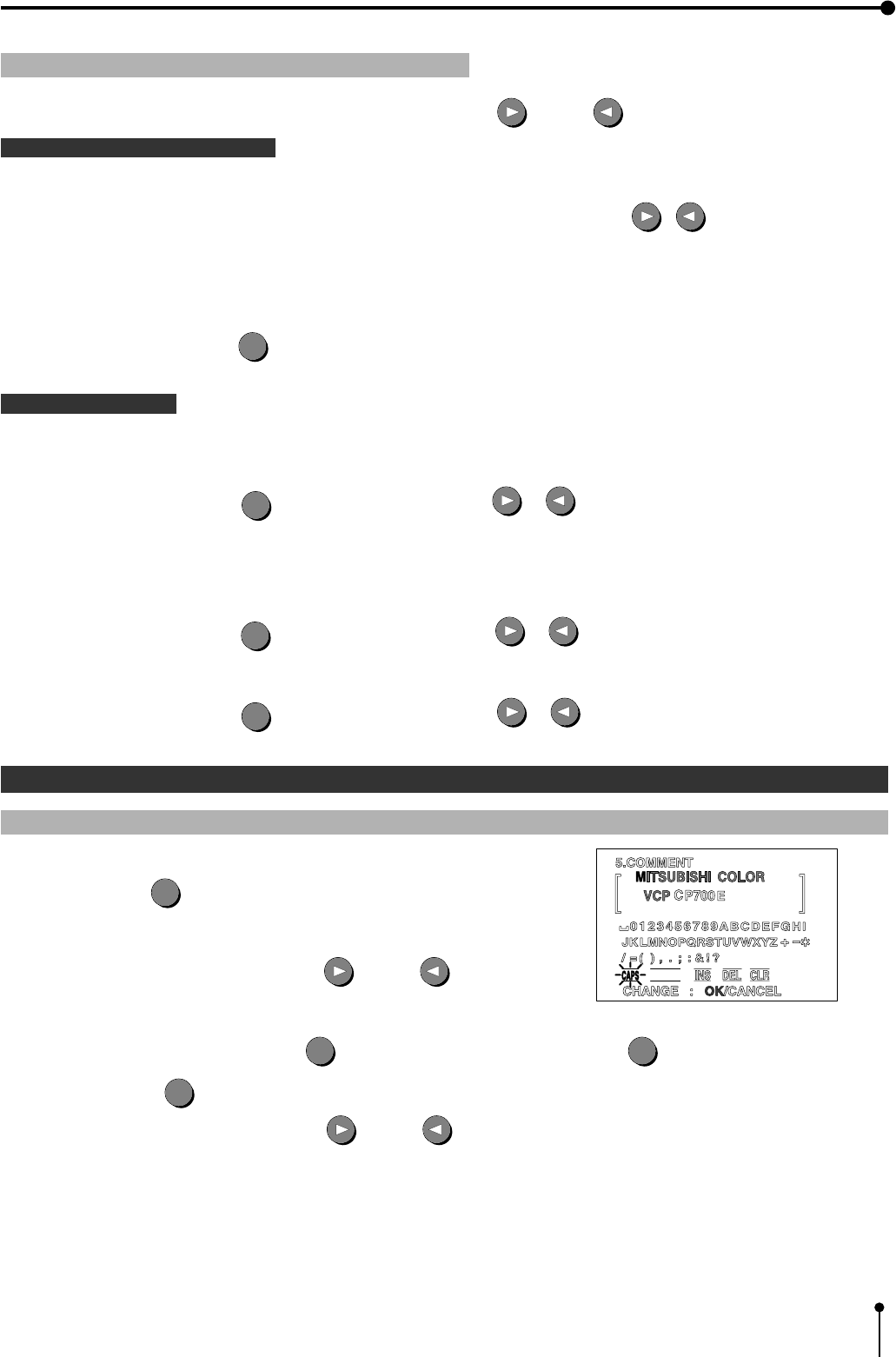
55
7. Setting the functions (Making a comment)
1 Editing command
, Selecting each command in editing mode by pressing RIGHT or LEFT shift button.
The letter inputting command
CAPS (Capital Letters ) ........... Capital letters / small letters
, When the SET button is pressed after selecting capital or small letter by pressing , button, the character
block is switched in order of capital letters → small letters → capital letters....
, “CAPS” is turned on and off indicated in red while selecting the capital letter.
, “CAPS” is turned on and off indicated in green while selecting the small caps letter.
, When pressing the SET
SET
button after selecting “SHIFT”, the special letters are displayed on the character block.
Editing command
INS ( Insert ) .............. Insert a space
,When pressing the SET
SET
button after selecting “INS” by or button, a space is inserted on the
preceding to the character indicated in red .
DEL ( Delete ) ............... Delete a letter
,When pressing the SET
SET
button after selecting “DEL” by or button, a letter indicated in red is deleted.
CLR ( Clear ) ............... Clear the whole comment
,When pressing the SET
SET
button after selecting “CLR” by or button, the whole comment is cleared.
1 Comment making procedure
1 Input mode selecting CAPS (capital letters/ small letters ) / SHIFT ( special letters)
1Press the MENU
MENU
button to select the command editing block.
,The selected command is turned on or off in red.
1Select the “CAPS” by pressing the RIGHT or LEFT shift button.
,The selected mode is turned on or off in red.
,Selecting “CAPS” → Press the SET
SET
button → Small letters → Press the SET
SET
button → Capital letters →
Press the SET
SET
button
1Select the “SHIFT” by pressing the RIGHT or LEFT shift button.
,The special letter is shown.
SHIFT
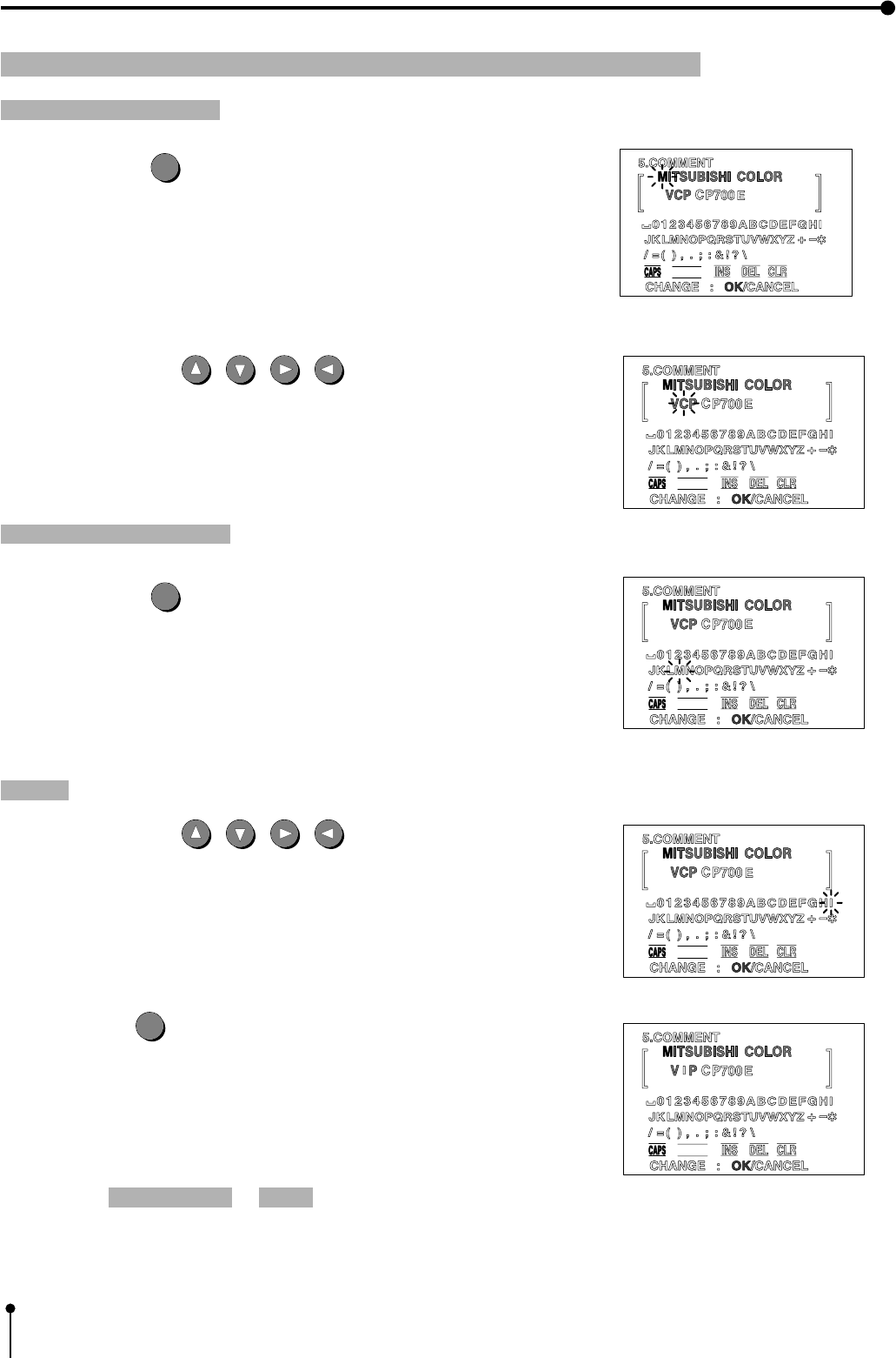
56
7. Setting the functions (Making a comment)
1 Inputting the letter
Selecting comment block
1Press the MENU
MENU
button to select comment display block.
,The selected block is displayed in green.
2Press the shift button , , , to select the inputting letter
position.
,Selected letter position is turned on or off in red.
Selecting characters block
3Press the MENU
MENU
button to select the character block.
,Selected block is displayed in green.
,Selected letter is turned on or off in red.
Setting
4Press the shift button , , , to select the inputting letter .
,Selected letter is turned on or off in red.
5Press the SET
SET
button.
,The letter is inputted on comment display.
,The letter position moves to the right on the comment display.
6Repeat the selecting a letter → setting steps to make a comment.
SHIFT
SHIFT
SHIFT
SHIFT
SHIFT
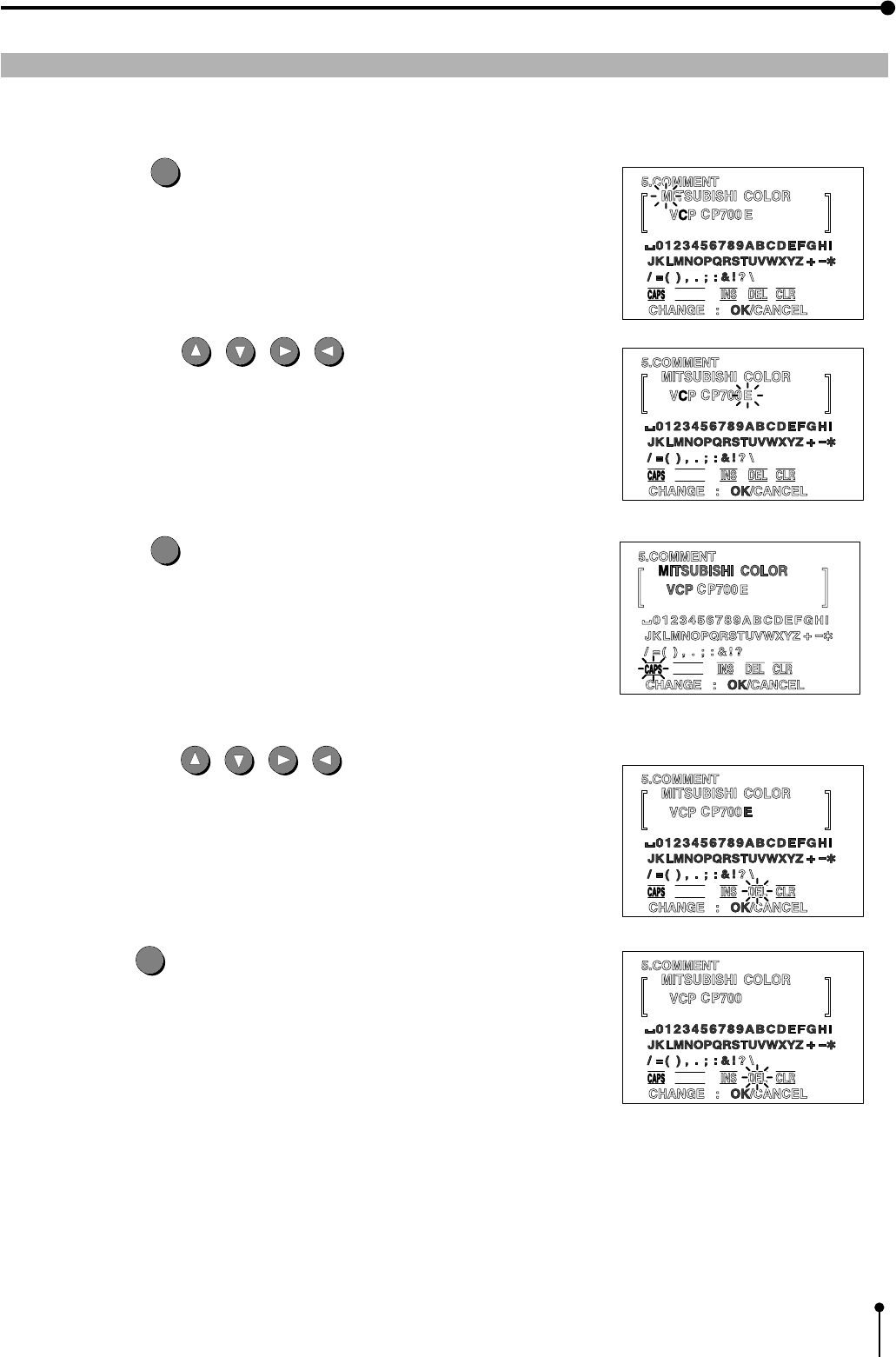
57
7. Setting the functions (Making a comment)
1 Inserting a space / deleting a character / Clearing the whole comment
Insert a space, delete a character or clear the whole comment by the following procedure.
(e.g.) In case of deleting “E”.
1Press the MENU
MENU
button to select comment display block.
,The selected block is displayed in green.
2Press the shift button , , , to select the deleting position.
3Press the MENU
MENU
button to select editor command block.
,The selected block is displayed in green.
4Press the shift button , , , to select “DEL” .
5Press the SET
SET
button.
,The selected command is executed.
SHIFT
SHIFT
SHIFT
SHIFT
SHIFT
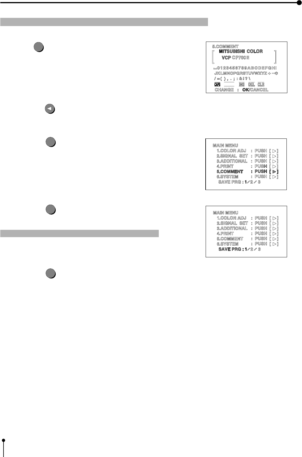
58
7. Setting the functions (Making a comment)
1 Close the comment menu
1Press the
MENU
button to select “CHANGE : OK/CANCEL” .
,“CHANGE” is displayed in blue.
2Press the shift button to select “OK” .
,In case of changing a comment , select the “CANCEL” .
3Press the SET
SET
button.
, “MAIN MENU” display is shown.
4Press the SET
SET
button.
,“SAVE PRG 1/2/3” is selected.
Note: Only one comment can be set among program 1,2 and 3.
5Press the SET
SET
button.
,The made comment is stored in the memory.
,Source image display is shown.
SHIFT
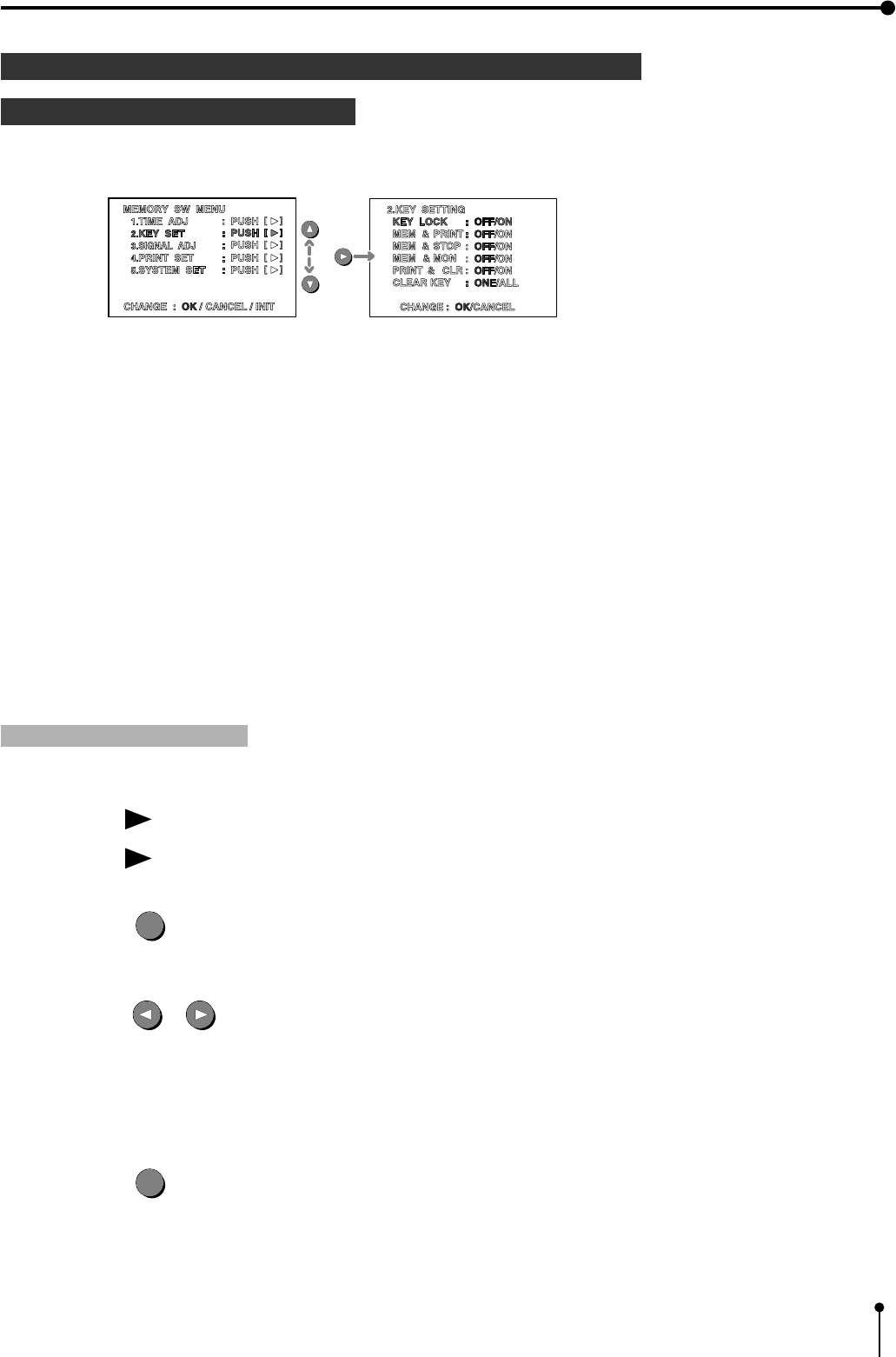
59
7. Setting the functions (Memory SW menu)
SETTING FUNCTIONS
2 MEMORY SW MENU
When pressing the POWER button while pressing the MEMORY button on the front panel with the POWER turned
off the MEMORY SW MENU is displayed.
(e.g.) Monitor display: MEMORY SW MENU → KEY SET → KEY LOCK
1 Item and setting are as shown below .
1.TIME ADJ ........................ Date / Present time
2. KEY SET ....................... Invalid the buttons' function, Memory button function
3. SIGNAL ADJ..................
Signal polarity, Signal level , Sync.signal, Signal timing , Horizontal signal starting position,
Color of printing image
4. PRINT SET .................... Printing direction , Printing speed, Paper cutting position , Gamma setting
5. SYSTEM SET ................ Initializing the user setting , Baud rate, RS-232C command type, Response command
Remote busy logic, Inform the number of remaining paper
CHANGE : OK / CANCEL/ INIT...... Complete, cancel or initialize the setting of the above function
CHANGE : OK /CANCEL/ INIT
This menu is shown in the lowest position on the “MEMORY SW MENU”.
Selecting “OK”, “CANCEL”. “INIT ( Initialize)” on the setting value of the menu 1-5.
Close the menu 1- 5 and normal display is shown.
1Press the SET
SET
button.
,“CHANGE” is indicated in blue.
2Press the shift or button to select “OK” , “CANCEL” or “INIT” .
,In case of changing a comment , select “CANCEL”
OK ..................... Fix the setting and normal display is shown.
CANCEL ............ Cancel the setting and MEMORY SW menu display is shown.
INIT .................... Initialize the setting of MEMORY SW menu.
3Press the SET
SET
button.
,The selected command is executed.

60
7. Setting the functions (Memory SW menu)
1TIME ADJ Setting the day and present time
TIME ADJ ( Time Adjust )
Function Setting the day and present time.
Refer to pages 11-13 for setting.
2KEY SET Setting the buttons' function
KEY LOCK
Function The function on the remote control buttons and all of the buttons of the unit except POWER button are
not available.
ON ..........The function on the remote control buttons except MEMORY, PRINT, MONITOR, MEMORY
PAGE are not available.
OFF ........All of the buttons on the remote control are available.
MEM & PRN (Memory and Print )
Function When pressing the MEMORY button, the image is automatically printed after the image is stored in the
memory. In the case of multi-image of different scenes, printing is executed after the last image is
stored in the memory.
ON ..........Storing the image and automatically printing
OFF ........The MEMORY button functions individually. The image memorized without being printed.
MEM & STOP (Memory and Stop)
Function When setting to “ON”, the next image is not overlaid in the memory after the last image is stored in the
memory .
ON ..........The image is not overlaid in the memory.
OFF ........The next image is stored in the memory.
When setting to "ON ", the image is stored in the memory again by pressing the PRINT or CLEAR
button.
MEM & MON ( Memory and Monitor )
Function Switching the monitor display to the source image or memory image.
ON ..........Display the memory image.
OFF ........Display the source image.
PRINT & CLR (Print and Clear )
Function After printing, the printed memory image is cleared.
ON ..........Clear the printed memory image.
OFF ........Does not clear the printed memory image.
Note: Do not set the number of prints two or more. Because the memorized image will clear after printing the
first sheet and there will be no print on the paper.
61
7. Setting the functions (Memory SW menu)
CLEAR KEY ( Memory and Clear )
Function Setting the CLEAR button function on the remote control.
ONE ........Pressing the CLEAR button on the remote control, the
memorized image being selected is cleared.
ALL .........Pressing the CLEAR button on the remote control, all of the stored
memorized images are cleared.
3SIGNAL ADJ Signal setting display
IN SYNC
Function Selecting the level of input sync.signal.
0.3 V ............ Composite Sync. of 0.3Vp-p level
TTL. SOG..... Composite Sync. of TTL level or Sync. On. G
Set the function according to inputting signal.
OUT SYNC
Function Selecting the level of output Composite Sync. signal of RGB signal.
0.3V ........0.3 Vp-p
TTL .........TTL level
Set the function according to connecting monitor.
SYNC
Function Select the polarity of output H+V Sync. of RGB signal.
POSI ............. Positive polarity
NEGA ............ Negative polarity
Set the polarity according to the signal of the connecting device.
Refer to the manual of connecting device.
RGB SOG OUT
Function Select the sync. signal of RGB analog output terminal.
OFF............ Composite Sync. signal output
ON.............. Sync. On.Green + Composite Sync. signal output
This is the function to switch between sending and not sending Sync. On Green signal on the output
signal. When set to “ON”, Sync. On Green and Composite Sync. signals are output. When set to “OFF”,
only Composite Sync. signal is output.
Set the function according to connecting monitor.
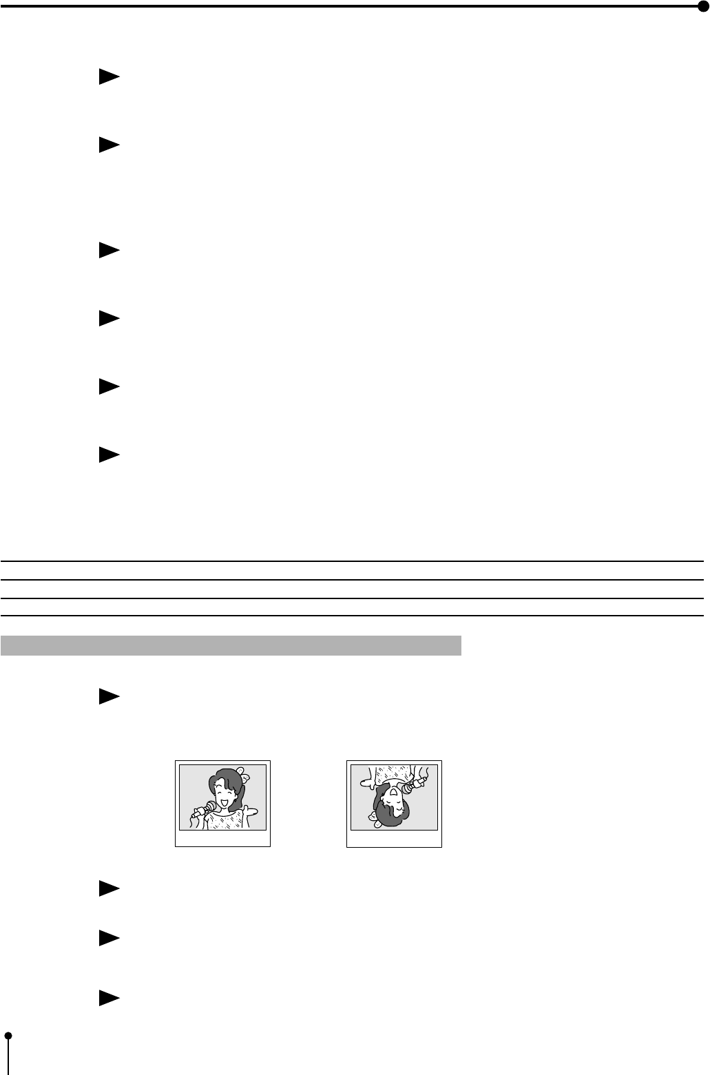
62
7. Setting the functions (Memory SW menu)
H -START (H - Position )
Function Adjust the H-position timing for the special signal .
NML (Normal) ..........Inputting PAL signal
FRONT ....................Inputting the special signal
When the image is imbalanced and cannot be corrected by H-POSI on basic printing, set to “FRONT”.
When setting to “FRONT”, the printing image may distorted in the special playback of VCR because
“AFC” (“MAIN MENU” → “2. SIGNAL SET” ) is invalid.
SPCL TIMING ( Special Timing )
Function Enlarge the setting area of H-POSI (MAIN MENU → SIGNAL SET , USER SIZE ADJ ).
ON ............... Enlarge the setting area
OFF ............. Initial setting
When inputting the signal except PAL , the image cannot be moved to desired position in H-POSI of
initial setting.
If this function is set to “ON”, the image can move to right and left direction beyond the initial setting.
When setting to “ON”, the next image may not be stored in the memory during printing.
MONITOR ADJ ( Monitor Adjust )
Function Adjusting the color of image on the monitor.
( This adjustment is invalid on printing.)
MON R-SUB ...........Adjusting the red-sub contrast
MON B-SUB ...........Adjusting the blue-sub contrast
Item Adjustment -32 Adjusting area +31
R-SUB Red-subcontrast add cyan .................................................... add red
B-SUB Blue-subcontrast add yellow.................................................. add blue
4PRINT SET Print setting 2
PRN DIR ( Print Direction )
Function Selecting the print direction.
NML ............. The margin is made on the lower position.
REV ............. The margin is made on the upper position.
This function is available on S-size paper. But printing is invalid on 2 multi-image, PHOTO 3 x 4, CARD .
PRN SPEED ( Print Speed )
Function Selecting the print speed.
NML ( Normal ) ......Normal speed
FAST ........................High speed
When setting to “FAST”, the color of printing image may be light.
Also, the image cannot be stored during printing.
NML REV
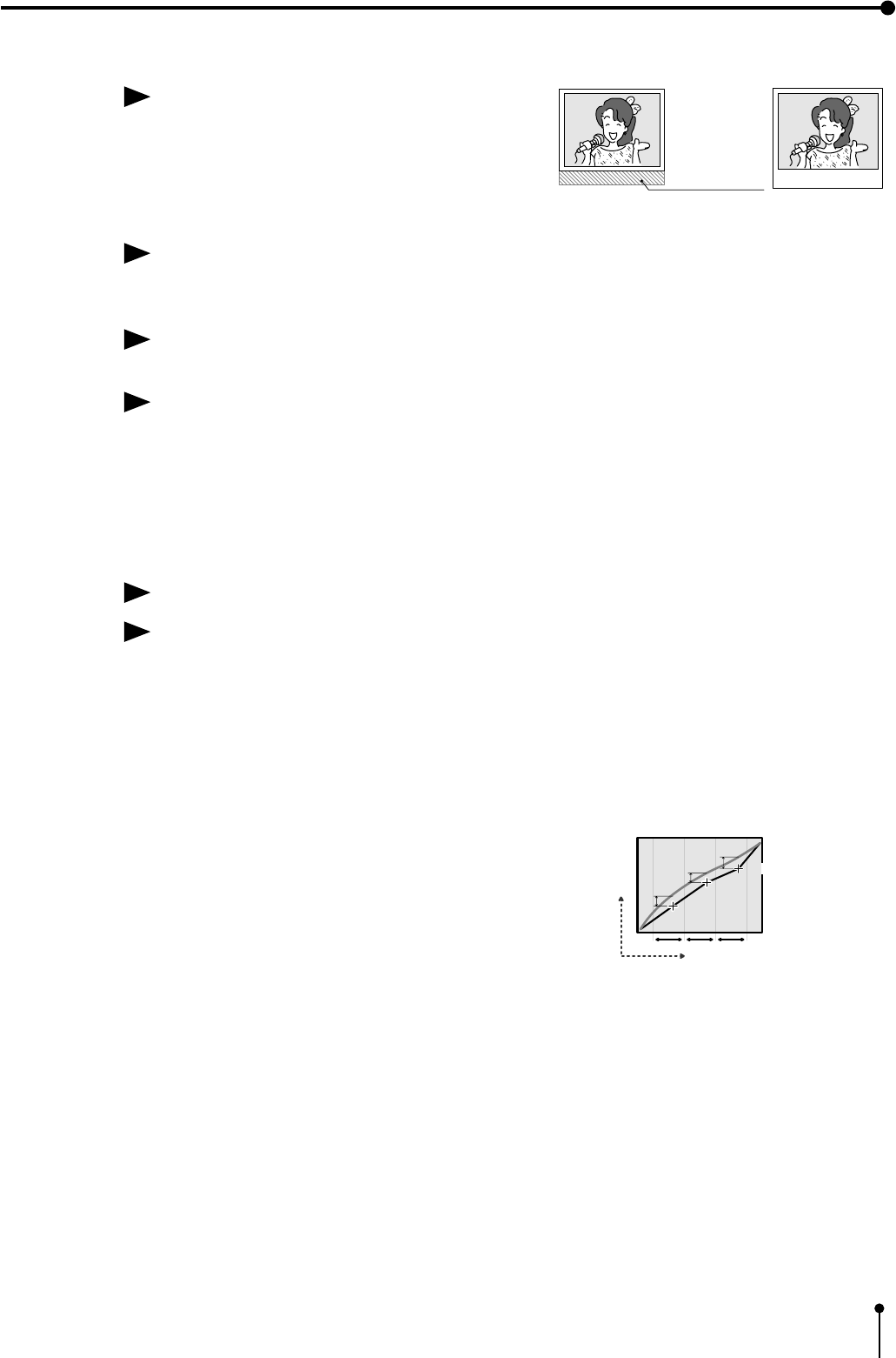
63
7. Setting the functions (Memory SW menu)
MARGIN CUT
Function Cut the print paper so that the upper margin is small.
ON ..........Small margin
OFF ........Behind the margin
This function is convenient when putting the print on prints on records or non-PVC sleeves for print
orchiving. This feature also saves paper.
V POSITION
Function Adjusting the vertical position of printing image.
Setting area - 40 to +40 ( Change each 2 lines)
When 2-image printing (selected “2” in “IMAGES”) on L size print paper, the printed image will not be
correct depending on memory size. It may be necessary to adjust part of the image in the UP, DOWN,
RIGHT or LEFT direction.
V POSITION function is to adjust the position for UP and DOWN direction of the image in memory and to
print the image in the normal cutting position. This function is available only when printing 2multi-image
on L size paper and selecting “2” in “IMAGES”.
ECHO GAMMA ADJ
Function Change the gamma value of “ECHO” for medical equipment.
The gamma curve is set for medical equipment in MAIN MENU → 4.PRINT GRAD : ECHO . When the
set gamma curve cannot be applied, this function is able to set according to connecting device. The set
value is applied to the value of ECHO.
The gamma characteristic of printed image can be changed by inputting the value of a, b and c on the
gamma curve.
a (cordinates of the x1 point, changed value y1)...... dark part of the image gets
y1 → + : brighter –: darker
b (cordinates of the x2 point, changed value y2 )...... the whole image get
y2 → + : brighter –: darker
c (cordinates of the x3 point, changed value y3 )...bright part of the image gets
y3 → + : brighter –: darker
• At X, input the location of a point on the curve to be moved to Y direction.
• At Y, input the amount of move.
• All the gamma characteristic changes by moving the “y” on a, b or c point.
• The setting area of the points (a, b and c ) is limited.
Select the item to be changed by LEFT or RIGHT shift button.
a: ( , ) ← → b : ( , ) ← → c : ( , )
Change the value by UP or DOWN shift button.
e.g.
1 b (x 2 value, y 2 changing value )..... Change the y value of all of the image.
2 Change the value of a and c.
a : x1=64 y1=0 b : x2=128 y2=0 c : x3=192 y3=0 is the initial setting of “GRAD:ECHO”.
X
Y
a:( x1,y1 )
b:( x2,y2 )
x:
cordinates of the x1value, y: changed value y1
c:( x3,y3 )
x1 cordinate
range x2cordinate
range x3cordinate
range
y1
y2
y3
a ( cordinates of the x1value, changed value y1)
darker lighter
Margin cut
ON OFF

64
7. Setting the functions (Memory SW menu)
5SYSTEM System setting 2
PRG ALL INIT ( Program All Initial )
All settings of 3 memory programs to store each function is initialized.
ON ..........Each setting function is initialized
OFF ........Not initialized
This function is available when selecting “OK” in the “CHANGE : OK/ CANCEL/INIT” of “MEMORY
SW MENU” and pressing the SET button.
Once this function is set to “ON” and the source image is displayed,the setting is initialized and the
image stored in the memory is cleared even if this function is set to “OFF”.
BAUD RATE
Function Setting the Baud Rate according to connected equipment. Refer to pages 19-21 .
COMMAND TYPE
Function Setting the RS-232C command type.
Select “A” or “B” according to connected equipment.
Normally, set the “COMMAND TYPE” to “A”. Refer to page 20.
RESPONSE
Function Select the RS-232C response from the unit to be sent back or not to the host computer.
Select “RET(return)” or “NO” .
RET (RETURN) .......The RS-232C response is sent back to the host computer.
NO ...........................The RS-232C response is not sent back to the host computer.
REMOTE BUSY
Function Setting the BUSY signal of remote terminal (REMOTE 1/ REMOTE 2) on the rear panel.
Normally, set the “REMOTE BUSY” to “H”.
Select “H” or “L” according to connected equipment. Refer to page 20.
H (HIGH) ............ The VCP cannot accept the remote input signal when the signal is “HIGH”.
L (LOW) ............ The VCP cannot accept the remote input signal when the signal is “LOW”.
REMAINING
Function Inform the number of remaining paper by a buzzer tone.
OFF ........This function is not available.
0 ..............The buzzer sounds five times as the point you set.
The setting area is 0 to 10.
Please observe the following precautions when you use this function.
• If a paper jam occurs, the remaining paper may not be informed correctly.
• Do not change the ink sheet size S to L ( or L to S) in the middle of using ink sheet.
• Make sure to replace the print paper and ink sheet at the same time.
• Make sure to use the new one when you set the ink sheet and print paper.
• Do not feed the print paper after you set the print paper.
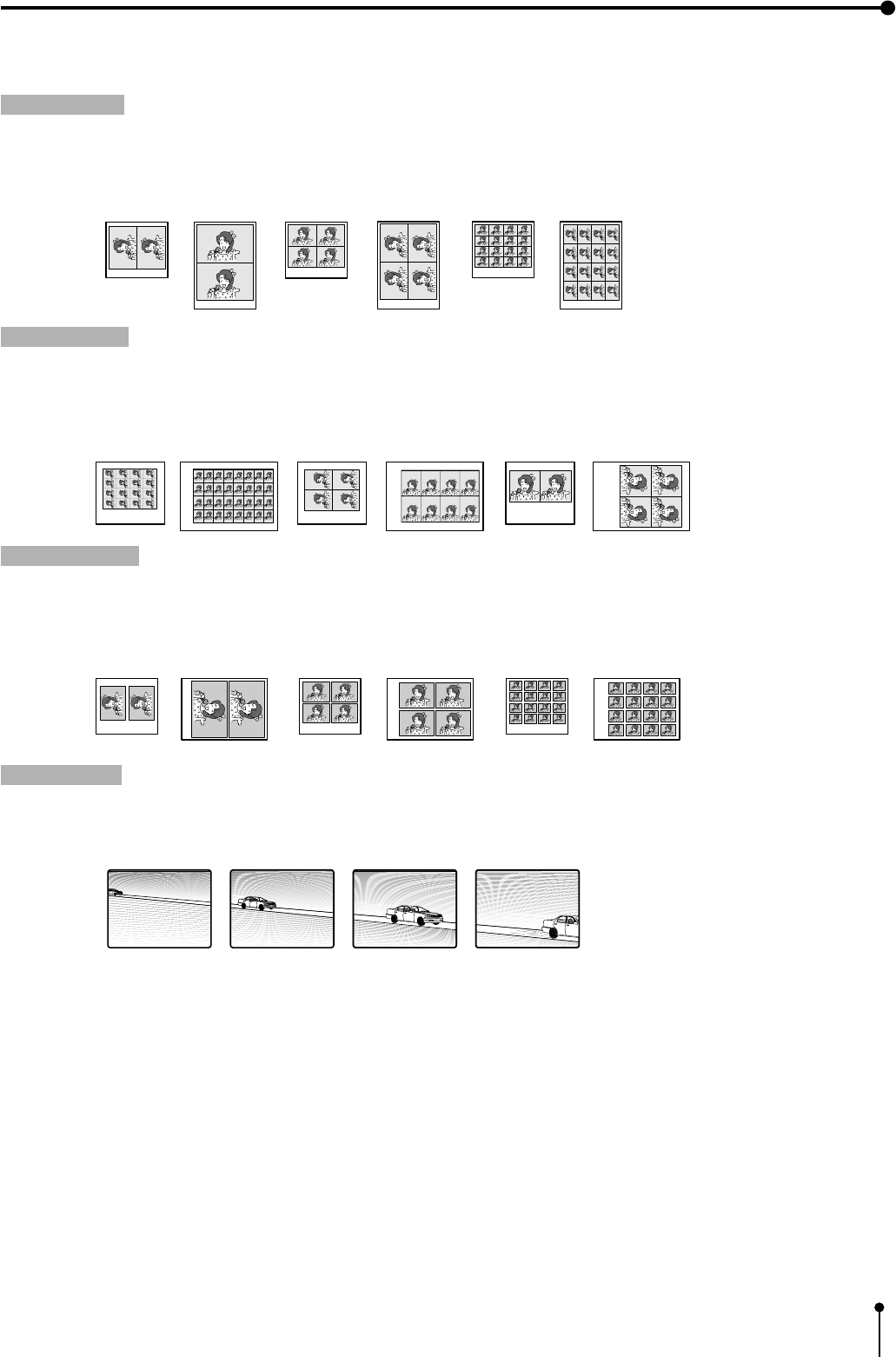
65
8. Printing procedures (Special prints)
The following printing is available.
,When “MEM&PRINT” in the KEY SETTING in MEMORY SW MENU is set to ON, the image is printed automatically after
memorizing the image (or memorizing the set number of images in MULTI mode).
Refer to pages 79 - 80.
1 MULTI prints SAME or DIFF .................................................................Pages 68 - 71
12,2s,4, or 16 images can be printed on a sheet.
1 2/2s-image 1 4-image 1 16-image
S-size paper L-size paper S-size paper L-size paper S-size paper L-size paper
2 PHOTO prints PHOTO .........................................................................Pages 72 - 74
1Photo prints can be made on two types of the sheet in the market and a card size sheet (suited size to stick on a business
card.)
1 CARD size (1.5 ✕ 2cm) 1 3 ✕ 4cm size 1 5 ✕ 5cm size
S-size paper L-size paper S-size paper L-size paper S-size paper L-size paper
3 Separate prints SEPARATE .................................................................Pages 74 - 76
1A white frame can be inserted between the images when two or more images are printed on a sheet.
1 2/2s-image 1 4-image 1 16-image
S-size paper L-size paper S-size paper L-size paper S-size paper L-size paper
4 Strobe prints STROBE ..........................................................................Pages 76- 80
1With this function, an image is stored in memory repeatedly at set intervals.
In case of multi-image setting, the images are stored in memory in the order of the set number of multi-image.
Example : S size paper, One image strobe memory
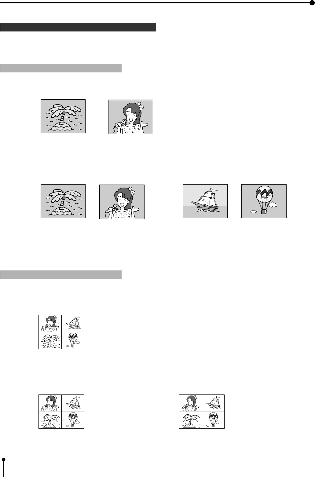
66
1Memory pages
AB
8. Printing Procedures (Special prints)
1The image size to be memorized is 1216 by 1200 dots. The following functions are available on this unit.
The following is an example of S size paper.
1 2-image prints (MULTI prints)
,In FRAME mode, 2 images can be memorized on one page.
example : VIDEO FRAME [ A B ] (Display on the monitor)
the image A and image B for 1 page (Only in the case of 2-images)
ABCD
the image A and image B for 1 page
(Only in the case of 2-images)
,In FIELD mode, 4 images can be memorized on 2 pages.
example : VIDEO FIELD [ A B C D ] (Display on the monitor)
the image C and image D for 1 page
(Only in the case of 2-images)
1 4-image prints (MULTI prints)
,In FRAME mode, 4 images can be memorized on one page.
example : VIDEO FRAME (Display on the monitor)
4 images on 1 page
,In FIELD mode, 8 images can be memorized on 2 pages.
example : VIDEO FIELD [ A B ] (Display on the monitor)
4 images on 1 page 4 images on 1 page
AB
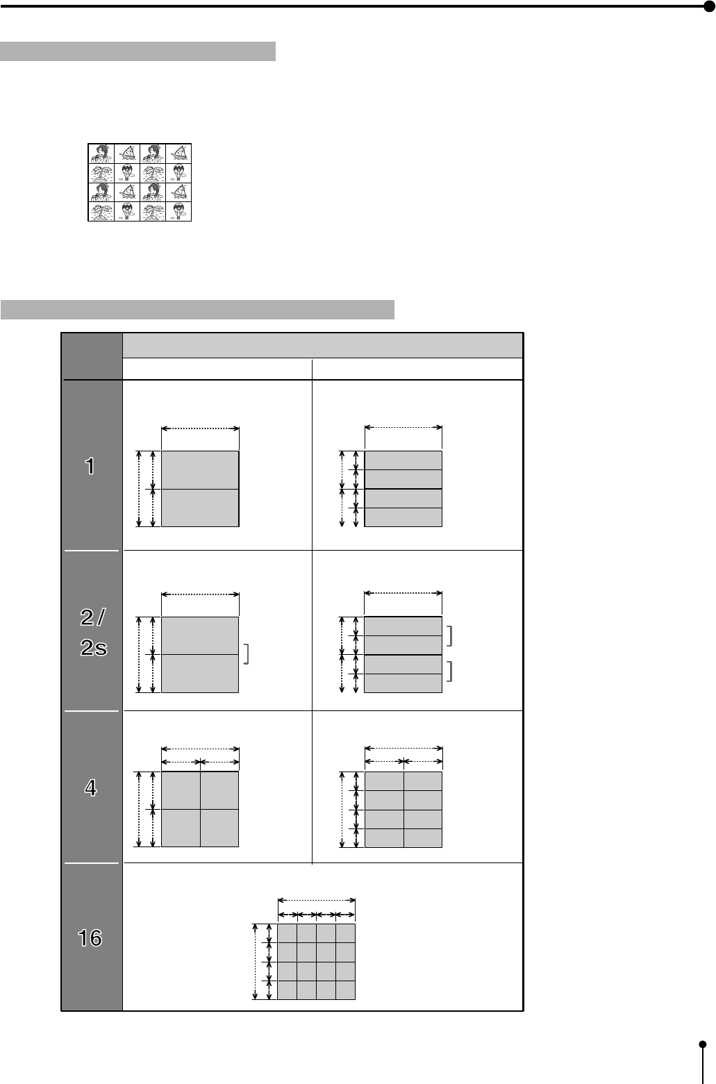
67
8. Printing Procedures (Special prints)
1 16-image prints (MULTI prints)
,In FRAME mode, 16 images can be memorized on 1 page.
example : VIDEO FRAME (Display on the monitor)
16 images on 1 page
1 Image size and the number of memory pages
1024 dot
500 dot
1000 dot
500 dot
A
B
1024 dot
500 dot
1000 dot
500 dot
A
B
1024 dot
500 dot
512 dot 512 dot
500 dot
1000 dot
BA DC
1000 dot
250 dot 250 dot
AB
CD
1024 dot
512 dot 512 dot
250 dot 250 dot
LM
NO
500 dot
250 dot 250 dot
1024 dot
500 dot
250 dot 250 dot
B
A
C
D
2 pages 4 pages
1 page
500 dot
250 dot 250 dot
1024 dot
500 dot
250 dot 250 dot
B
A
C
D
Only 2 images
A and B for
1 page
Only 2 images
A and B for
1 page
C and D for
1 page
A 1 page
B 1 page
1 page
A 1 page
B 1 page
C 1 page
D 1 page
A 1 page
B 1 page
FRAME FIELD
Number of memory pages
No. of
images
2 pages
1 page 2 pages
250 dot 250 dot
1024 dot
250 dot 250 dot
ABCD
EFGH
IJKL
MNOP
256 dot 256 dot256 dot 256 dot
1000 dot
1 page
1 page
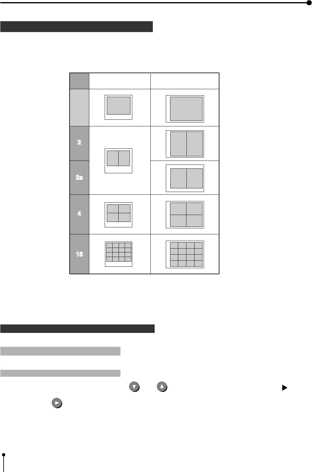
68
1 MULTI PRINTS
8. Printing Procedures (Special prints)
12, 2s, 4 or 16 images can be printed on a sheet.
,The following prints are available.
example : “W” is selected on “SIZE” in 6.SYSTEM. “OFF” is selected on “SEPARATE” in 3.ADDITIONAL.
“A” shows the direction of images.
1OPERATION
1 Setting the multi-print menu
Setting the multi-print function
1Press the MENU button. Then, Press the DOWN or UP shift button to select “3. ADDITIONAL PUSH [ ]”.
2Press the RIGHT shift button to open “3. ADDITIONAL”.
A
A
A
A
S size prints L size prints
Setting of
the No. of
images
2
1616
One
image
printing
A
4
A
A
AAA
AAAA
AAAA
AAAA
AAA
AAAA
AAAA
AAAA
A
A
A
AA
A
AA
A
A
A
2s

69
8. Printing Procedures (Special prints)
3Press the DOWN or UP button to select “MULTI : OFF/ON”. Then, press the RIGHT button to select
“ON”.
,“MODE : SAME/DIFF/PHOTO” is displayed on the menu screen.
4Press the DOWN button to select “MODE : SAME/DIFF/PHOTO”. Then, press the RIGHT button to
select “SAME” or “DIFF”.
,When “SAME” is selected, a multi-image (2, 2s, 4 or 16 images) of the same image can be printed.
,When “DIFF” is selected, a multi-image (2, 2s, 4 or 16 images) of the different images can be printed.
5Press the DOWN shift button to select “IMAGES : 2/2s/4/16”. Then press the RIGHT shift button to select 2, 2s,
4 or 16.
,The multi-image setting is completed.
,When “2” or “2s” is selected, 2 images can be stored in memory.
,When “4” is selected, 4 images can be stored in memory.
,When “16” is selected, 16 images can be stored in memory.
1 Displaying the image from input signal (source image)
1Press the SET
SET
button.
,“CHANGE : OK/CANCEL” is selected.
,When changing the multi-print function, select “CANCEL”.
2Press the SET
SET
button.
,The MAIN MENU is displayed.
3Press the SET
SET
button.
,“SAVE PRG 1/2/3” is selected.
,This menu is used to store the setting in any one of 3 programs (1, 2 or 3).
4Press the RIGHT or LEFT button to select the program number 1, 2 or 3 to store the setting.
,The setting will be overlaid. In case of keeping the stored program, do not select the program No. in which the setting is
stored.
5Press the SET
SET
button.
,The source image (image from the input signal) is displayed.
,“IMAGES : 2 / 2s/ 4/ 16” is displayed on the lower line.

70
8. Printing Procedures (Special prints)
Storing an image in any position
1Press the DISPLAY button to display the set conditions.
2Press the FIELD/FRAME button on the remote control to select FIELD or FRAME.
3Press the MONITOR button and select the source image (“LIVE” is displayed on the monitor.) to display the image to be stored
in memory.
4Press the MEMORY button to store the image to be printed.
1 Storing images in memory
,When “MODE” is set to “DIFF” and “IMAGES” to “4” or “16”, store the set number of images in memory by repeating
“displaying the image to be stored in memory on the monitor” → “pressing the MEMORY button” →....
When an image is stored in memory, the source image (“LIVE” is displayed on the monitor.) is displayed approx. 1 second
after the memorized image is displayed.
,When “MODE” is set to “DIFF” and “IMAGES” to “2” or “2s”:
FRAME .... One image can be stored in memory page A and B.
FIELD ....... One image can be stored in memory page A and B, or C and D.
,When “MODE” is set to “DIFF” and “IMAGES” to “4”:
FRAME .... [A B ] and [ABCD] are not displayed on the screen.
4 images can be stored in only 1 memory page.
FIELD ....... 4 images can be stored in memory page A or B.
,When “MODE” is set to “DIFF” and “IMAGES” to “16”:
FRAME .... [A B ] and [ABCD] are not displayed on the screen.
16 images can be stored in only 1 memory page.
FIELD ....... [A B ] and [ABCD] are not displayed on the screen.
16 images can be stored in only 1 memory page.
,When “MODE” is set to “SAME” :
FRAME .... An image can be stored in memory page A or B only once.
FIELD ....... An image can be stored in A, B, C or D only once.
When “MODE” is set to “DIFF” and “IMAGES” to 4 or 6
1Press the DISPLAY button to display the set conditions.
2Press the MONITOR button. Select source image (“LIVE” is displayed on the monitor.) to display the image to be stored in
memory.
3Press the MONITOR button to display the memorized image. (“MEMORY” is displayed on the screen.)
,When “IMAGES” is set to 4 and FIELD mode is selected, press the MEMORY PAGE button to select the memory page.
4Press the DISPLAY button to display the set conditions.
,The memory page number where the image can be stored is indicated.
The position number where the image can be stored is indicated in green.
5Press the shift buttons to determine the position to store the image.
,The image is stored in the selected position.
6Press the MEMORY button to store the image to be printed.

71
8. Printing Procedures (Special prints)
,When “MODE” is set to “SAME”, or “MODE : DIFF” and “IMAGES” is set to 2(or 2s), only one image is displayed on the monitor
screen.
1Press the DISPLAY button to display the set conditions.
2Press the MONITOR button. Select source image (“LIVE” is displayed on the monitor.) to display the image to be stored in
memory.
3Press the MEMORY PAGE button to select the memory page to store the image.
,The selected memory page is indicated in green in [A B] or [A B C D].
,When the MEMORY PAGE button is pressed, the position to store the image is switched. The switched position is indicated
in green in [A B] or [A B C D].
,Select the previous character of the page where the image is to be stored.
(Select “C” to store the image in page B. The initial setting is “PAGE INC : ON”.)
,When “MODE” is set to “SAME” :
FRAME ..... Select [A] or [B]
FIELD ...... Select [A] [B] [C] or [D]
,When “MODE” is set to “DIFF” and “IMAGES” to “2”(or 2s) :
FRAME ..... Select [A] or [B]
FIELD ...... Select [A] or [B] , or [C] or [D]
4Press the MEMORY button to store the image in memory.
,When pressing the MONITOR button, selecting MEMORY (memorized image) and then pressing the MEMORY PAGE
button, the image stored in memory can be checked.
1 Printing the images
When “MODE” is set to “SAME”, or “MODE” is set to “DIFF” and “IMAGES” to 2(or 2s)
1Press the MONITOR button to display the memorized image. (“MEMORY” is displayed on the monitor.).
,In the following cases, select the memorized image to be printed by pressing the MEMORY PAGE button.
1. “MODE” is set to “DIFF” and “IMAGES” to “2” or “2s”.
2. “IMAGES” is set to “4” and FIELD mode is selected.
3. “MODE” is set to “SAME”.
,The selected memory page is indicated in green in [A B] or [A B C D].
,When selecting any one character in [A B] or [C D], [A B] or [C D] is selected.
2Press the PRINT button.
,The memorized multi-image is printed.
Note :
,When 2 images are printed on a S size paper, comments may not be fully printed.
,When 2 images are printed on a L size paper, the images may not be fully printed.
In this case, adjust the position of the images by “V POSITION” of “4. PRINT SETTING” of “4. PRINT SET” in memory SW
menu.
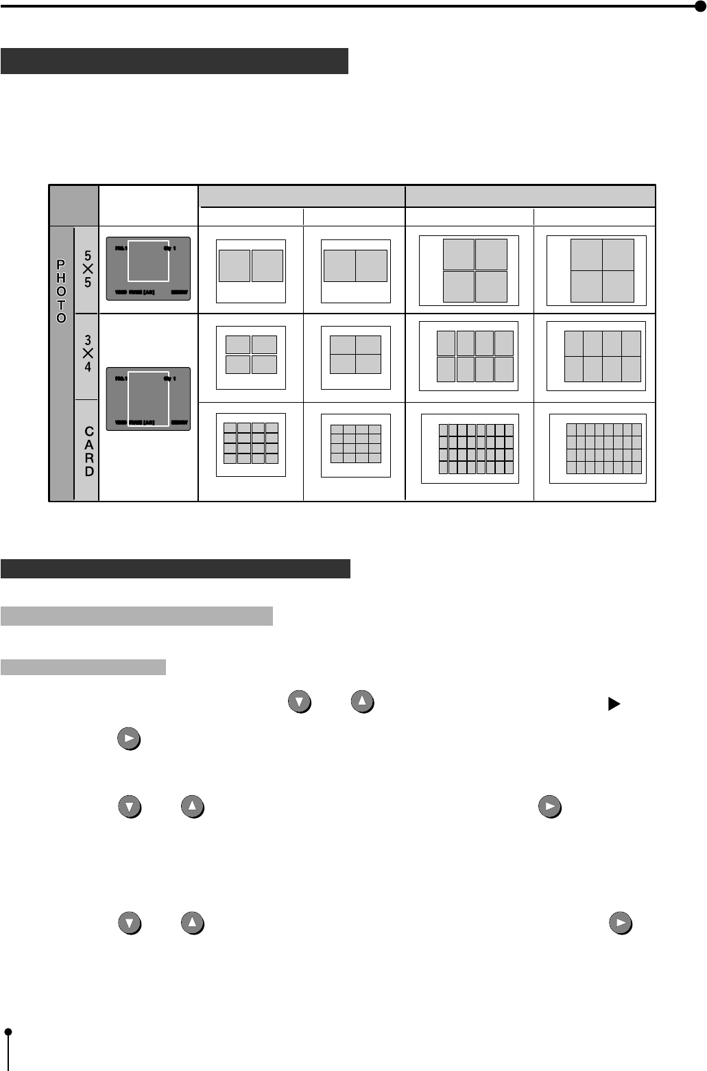
72
8. Printing Procedures (Special prints)
2 PHOTO PRINTS
1PHOTO print is a function to print the images on the photo size (3x4cm, 5x5cm) and card size (2x1.5cm ).
,CARD size print is suited to stick on a business card.
,The following prints are available.
1OPERATION
1 Setting PHOTO print menu
Setting PHOTO function
1Press the MENU button. Then press the DOWN or UP button to select “3. ADDITIONAL PUSH [ ]”.
2Press the RIGHT button to select “3. ADDITIONAL”.
example : “W” is selected on “SIZE” in 6.SYSTEM
“A” shows the direction of images.
3Press the DOWN or UP button to select “MULTI : OFF/ON”. Then press the RIGHT button to select
“ON”.
4Press the DOWN or UP button to select “MODE : SAME/DIFF/PHOTO”. Then, press the RIGHT button to
select “PHOTO”.
,“MODE : SAME/DIFF/PHOTO” is displayed on the menu screen.
,“IMAGES : 2 / 2s/ 4/ 16” is displayed on the lower line.
,“IMAGES : CARD / 3*4 /5*5” is displayed on the menu screen.
S size prints
Memorized image
on the monitor
L size prints
Separate ON Separate OFF Separate ON Separate OFF
Setting
the No.of
prints
AA
AA
A
A
A
A
A
A
A
A
A
A
A
A
A
A
A
A
AA
AA
AAAA
AAAA
AAAA
AAAA
AA
AA
A
A
A
A
A
A
A
A
AAAAAAAA
AAAAAAAA
AAAAAAAA
AAAAAAAA
A
A
A
A
A
A
A
A
A
A
A
A
A
A
A
A
A
A
A
A
A
A
A
A
A
A
A
A
A
A
A
A
AAAA
AAAA
AAAA
AAAA
A
A
VIDEO FRAME [ A B ] MEMORY
PRG. 1 Q'ty 1
VIDEO FRAME [ A B ] MEMORY
PRG. 1 Q'ty 1
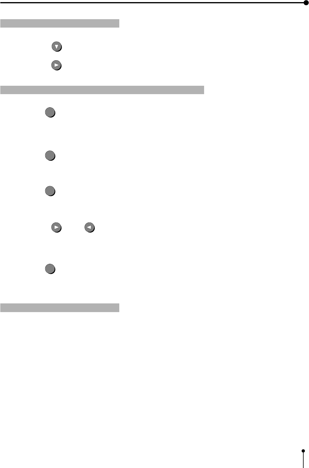
73
8. Printing Procedures (Special prints)
1Press the SET
SET
button.
,“CHANGE : OK/CANCEL” is selected.
,When changing the PHOTO print setting, select “CANCEL”.
1 Selecting the size
1Press the DOWN button to select “IMAGES : CARD / 3*4 /5*5” menu.
5Press the SET
SET
button.
,The source image (image from the input signal) is displayed.
2Press the RIGHT button to select “CARD” , “3*4” or “5*5”.
1 Displaying the image from input signal (source image)
2Press the SET
SET
button.
,The MAIN MENU is displayed.
3Press the SET
SET
button.
,“SAVE PRG 1/2/3” is selected.
,This menu is used to store the setting in any one of 3 programs (1, 2 or 3).
4Press the RIGHT or LEFT button to select the program number 1, 2 or 3 to store the setting.
,The setting will be overlaid. In case of keeping the stored program, do not select the program No. in which the setting is
stored.
1 Storing images in memory
1Press the DISPLAY button to display the set conditions.
2Press the FIELD/FRAME button on the remote control to select FIELD or FRAME.
3Press the MONITOR button and select the source image (“LIVE” is displayed on the monitor.) to display the image to be stored
in memory.
4Press the MEMORY PAGE button to select the memory page to store the image.
,The selected memory page is indicated in green in [A B] or [A B C D].
,When the MEMORY PAGE button is pressed, the position to store the image is switched. The switched position is indicated
in green in [A B] or [A B C D].
,Select the previous character of the page where the image is to be stored.
(Select “B” to store the image in “A”. The initial setting is “PAGE INC : ON”.)
5Press the MEMORY button to store the image in memory.
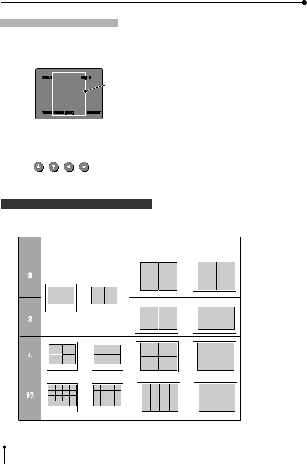
74
8. Printing Procedures (Special prints)
3 SEPARATE PRINT
1 Printing the images
1Press the MONITOR button to display the memorized image. (“MEMORY” is displayed on the monitor.)
example : When “3x4” or “CARD” is selected.
,A white frame is indicated on the displayed image.
,The image within the white frame is photo-printed.
,The following prints are available.
2Press the MEMORY PAGE button to select the memory page to print.
,The selected memory page is indicated in green in [A B] or [A B C D].
3Press the , , , buttons to move the white frame to determine the print area.
4Press the PRINT button.
,The set PHOTO-image is printed.
1A white frame can be inserted between two or more images.
example : “W” is selected on “SIZE” in 6.SYSTEM
“A” shows the direction of images.
A
VIDEO FRAME [ A B ] MEMORY
PRG. 1 Q'ty 1
The white frame moves
with the SHIFT buttons.
S size prints L size prints
Separate ON Separate OFF Separate ON Separate OFF
Setting of
the No. of
prints
2
4
16
s
s
2s
A
A
A
A
A
A
A
AA
A
A
A
AA
AA A A A
AA
AAAA
AAAA
AAAA
AAAA
AAAA
AAAA
AAAA
AAAA
AA
AA AAA
A
A
A
A
A
A
A
A
A
A
A
A
A
AA
A
A
A
A
A
A
A
A
A
A
A
A
A
A
A
A
A
75
1OPERATION
1 Setting the multi-print and photo-print menus
Setting multi-print and photo-print functions
1Press the MENU button. Then, press the UP or DOWN shift button to select “3. ADDITIONAL PUSH [ ]”.
3Press the DOWN shift button to select “MULTI : OFF/ON”. Then press the RIGHT shift button to select “ON” .
4Set the multi-image type (2, 2s, 4 or 16) or photo print size.
,“MODE : SAME/DIFF/PHOTO” is displayed on the menu screen.
,“IMAGES : 2 / 2s/ 4/ 16” is displayed on the lower line.
,Set “MODE : SAME/DIFF/PHOTO” and “IMAGES : 2/2s/4/16 or CARD/3*4/5*5” menus.
,Refer to 1 MULTI PRINT and 2 PHOTO PRINT for the multi-image type.
2Press the RIGHT shift button to select “3. ADDITIONAL”.
1 Setting the SEPARATE function
5Press the DOWN shift button to select “SEPARATE : OFF/ON” .
6Press the RIGHT shift button to select “ON”.
1 Displaying the source image (image from the input signal)
7Press the SET
SET
button.
,“CHANGE : OK/CANCEL” is selected.
,When changing the setting, select “CANCEL”.
8Press the SET
SET
button.
,The MAIN MENU is displayed.
9Press the SET
SET
button.
,“SAVE PRG 1/2/3” is selected.
,This menu is used to store the setting in any one of 3 programs (1, 2 or 3).
APress the RIGHT or LEFT shift button to select the program number 1, 2 or 3 to store the setting.
,The setting will be overlaid. In case of keeping the stored program, do not select the program No. in which the setting is
stored.
8. Printing Procedures (Special prints)
76
8. Printing Procedures (Special prints)
BPress the SET
SET
button.
,The source image (image from the input signal) is displayed.
1 Storing images in memory / Printing the images
1Store the images to be printed in memory.
,Refer to 1 MULTI PRINT or 2 PHOTO PRINT for storing images in memory.
2Press the PRINT button.
,The set SEPARATE images are printed.
Note :
,The distance between images in multi-print is different between on the monitor and the printed image.
,The image size changes according to the “SIZE” in “6. SYSTEM MENU”.
When the images of different size are memorized in one page, the margin is determined according to the largest width of the
image in the page.
4 STROBE PRINTS
,The interval of memorization can be set as follows:
,1/13 sec • 1/5 sec • 1/2.5 sec • 1 sec • 2 sec • 5sec • 10 sec • 30 sec ..... every second
,1 min • 2 min • 5min • 10min • 30 min ...................................................................... every minute
,1hr ................................................................................................................................................ every hour
,Images can not be memorized during printing while images are fully stored in memory page.
When the interval of the strobe time is a value lower than the automatic capture and print time interval, the printer will not be
able to the image because print time is longer than strobe time. Adjust strobe time by selecting a higher value.
(Example : interval of 10 seconds or less in FIELD mode and interval of 30 seconds or less in FRAME mode)
1 OPERATION
1 Selecting FIELD or FRAME
1 Setting STROBE function
1Press the MENU button. Then press the UP or DOWN button to select “3. ADDITIONAL PUSH [ ]”.
2Press the RIGHT button to select “3. ADDITIONAL”.
3Press the UP button to select “STROBE : OFF”
4Press the RIGHT button to select “STROBE : 1/13 .... 1hr”.
,Each time the RIGHT or LEFT button is pressed, the interval of image memorization is switched.

77
1 Setting 1-image/multi-image memory
8. Printing Procedures (Special prints)
1 When memorizing 1 image in STROBE mode
This setting is used to memorize 1 image in memory page [A B] (FRAME) or [A B C D] (FIELD).
1Set the mode to 1-image.
Select “OFF” in “MULTI : OFF” in “3. ADDITIONAL”.
2Set the page increment function to ON.
Set the “PAGE INC” to ON in “6. SYSTEM”. (The initial setting is “ON”.)
,In FRAME mode, the image is memorized in the stored in memory page in order of page [A] → page [B]→ page [A]....
,To memorize images in page [A] and [B] only once, (not memorizing images repeatedly) set “MEM&STOP” to“ON” in “2.
KEY SET” from MEMORY SW MENU.
,When “PAGE INC” is set to OFF, images are memorized in page [A] repeatedly.
1 When memorizing multi- image (2, 2s, 4 or 16 images) in STROBE mode
This setting is used to memorize multi-image in order in one memory page.
1Set the mode to MULTI.
Select “ON” in “MULTI” in “3. ADDITIONAL”.
2Set the number of images and print size.
Set “MODE : SAME/DIFF/PHOTO” and “IMAGES : 2/ 2s/ 4/ 16” in “3. ADDITIONAL”.
,Refer to 1 MULTI PRINT for setting the number of multi-image.
,When “DIFF” is selected in “MODE” and 2, 2s, 4 or 16 is selected in “IMAGES”, 2, 2s, 4 or 16 images are stored in memory
in order at the set interval.
When the images are fully stored in memory page, the strobe memorization stops.
,When “MODE” is set to “SAME” or “PHOTO”, the memorization status is as same as one image memorization.
78
8. Printing Procedures (Special prints)
1 Displaying the source image (image from the input signal)
1Press the SET
SET
button.
,“CHANGE : OK/CANCEL” is selected.
,When changing the setting, select “CANCEL”.
2Press the SET
SET
button.
,The MAIN MENU is displayed.
3Press the SET
SET
button.
,“SAVE PRG 1/2/3” is selected.
,This menu is used to store the setting in any one of 3 programs (1, 2 or 3).
4Press the RIGHT or LEFT button to select the program number 1, 2 or 3 to store the setting.
,The setting will be overlaid. In case of keeping the stored program, do not select the program No. in which the setting is
stored.
5Press the SET
SET
button.
,The source image (image from the input signal) is displayed.
1 Storing images in memory
1Press the DISPLAY button to display the set conditions.
2Press the FIELD/FRAME button on the remote control to select FIELD or FRAME.
3Press the MONITOR button and select the source image (“LIVE” is displayed on the monitor.) to display the image to be stored
in memory.
4Press the MEMORY button.
,The set strobe memory starts.
,When the strobe memory is set on multi-image, the position of image memory is automatically set.
,To store the images in strobe memory again while “MEM&STOP” is set to ON at multi-image and strobe memory setting,
press the CLEAR button or press the MEMORY button after completing printing.
The strobe images are stored in the 2nd page.
,When “MODE” is set to “SAME”, the images are stored in [A B] or [A B C D] repeatedly.
When “MODE” is set to “DIFF”, “IMAGES” to “4” and FIELD mode, 4 images are stored in [A] or [B] and then image
memorization stops.
Images can be stored in the other memory page by pressing the MEMORY PAGE button.
When “MODE” is set to “DIFF” and “IMAGES” to “16”, [A B] and [A B C D] are not indicated. The images can be stored in
one memory page.
After storing 16 images in memory, image memorization stops.
When pressing the MEMORY button again, images are stored in memory again.
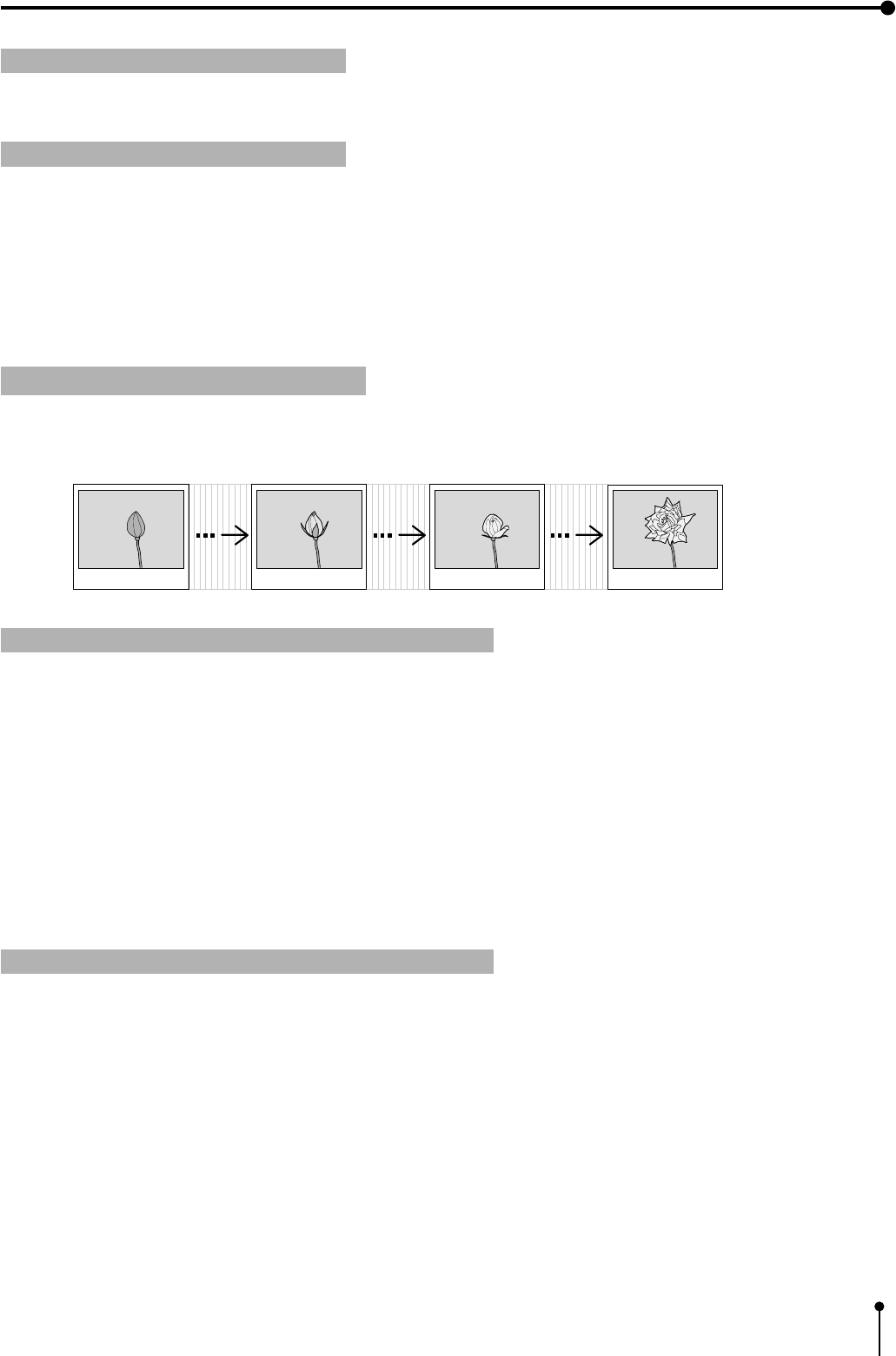
79
8. Printing Procedures (Special prints)
1 Interrupting strobe memory
1Display the desired image on the monitor.
,The image stored in memory is printed.
2Press the PRINT button.
,When any buttons on the remote control except MEMORY button is pressed, the strobe memory is interrupted.
1 Pressing the PRINT button
To print the images stored in the strobe memory, follow the following procedures after interrupting the strobe memorization.
Setting the automatic interval printing
By combining STROBE printing and MEMORY printing, automatic interval printing is available. This is the function where the
images are stored in memory at the set interval and printed repeatedly.
1 Automatic interval prints (1 image )
This is the function where one image is stored in memory page ([A or B] in FRAME mode or [A, B, C or D] in FIELD mode) in
order at set interval and printed repeatedly.
1Set 1 image mode.
Set “MULTI : OFF/ON” to “OFF” in “3. ADDITIONAL” from the MAIN MENU.
2Set the PAGE INC to “ON”.
Set the “PAGE INC : ON/OFF” to “ON” in “6. SYSTEM” from the MAIN MENU.
3Set the “MEM&PRINT” to “ON”.
Set the “MEM&PRINT : OFF/ON” to “ON” in “2. KEY SETTING” from the MEMORY SW MENU.
1 Automatic interval prints (multi-image )
This is the function where set number of multi-images are stored in memory page ([A and B] in FRAME mode or [A, B, C and D]
in FIELD mode) in order at set interval and printed repeatedly.
1Set multi-image mode.
Set “MULTI : OFF/ON” to “ON” in “3. ADDITIONAL” from the MAIN MENU.
2Set the number of images in a memory page and print size
Set “MODE : SAME/DIFF/PHOTO” and “IMAGES : 2/2s/4/16” in “3. ADDITIONAL”.
,When “MODE” is set to “SAME” or “PHOTO”, the image is stored and printed as the same status as 1-image memory.
,When “MODE” is set to “DIFF” and “IMAGES” to 2, 2s, 4, or 16 images are stored in a memory page at the set
interval.
,The strobe memory does not function while the images are being printed. After completing printing, memorizing and
printing images starts again.
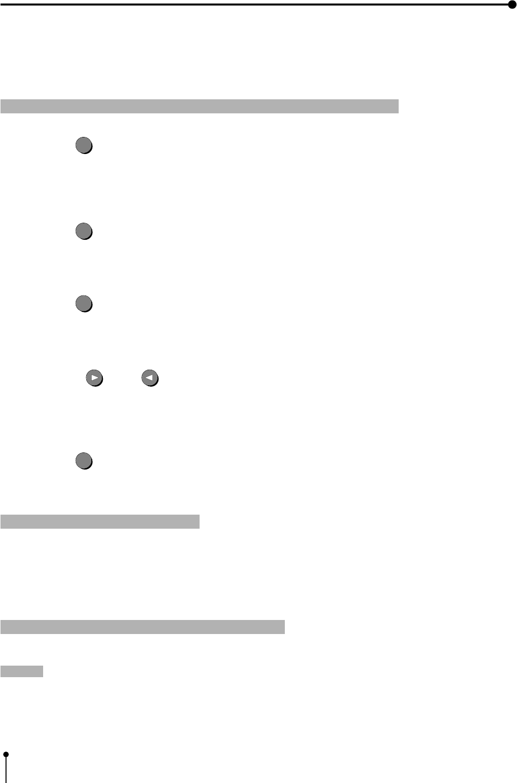
80
8. Printing Procedures (Special prints)
3Set the “PAGE INC” to “ON”.
Set the “PAGE INC : ON/OFF” to “ON” in “6. SYSTEM” from the MAIN MENU.
4Set the “MEM&PRINT” to “ON”.
Set the “MEM&PRINT : OFF/ON” to “ON” in “2. KEY SETTING” from the MEMORY SW MENU.
Displaying the source image (image from the input signal)
1Press the SET
SET
button.
,“CHANGE : OK/CANCEL” is selected.
,When changing the setting, select “CANCEL”
2Press the SET
SET
button.
,The MAIN MENU is displayed.
3Press the SET
SET
button.
,“SAVE PRG 1/2/3” is selected.
,This menu is used to store the setting in any one of 3 programs (1, 2 or 3).
4Press the RIGHT or LEFT button to select the program number 1, 2 or 3 to store the setting.
,The setting will be overlaid. In case of keeping the stored program, do not select the program No. in which the setting is
stored.
5Press the SET
SET
button.
,The source image (image from the input signal) is displayed.
Pressing the MEMORY button
Note :
1Display the desired image for the automatic interval printing on the monitor.
2Press the MEMORY button.
,The set automatic interval printing starts.
1 Interrupting automatic interval prints
,When the STOP button on the remote control is pressed, the automatic interval print is interrupted.
,“MEM&STOP” and “MEM&PRINT” function after the last image of the multi-image is stored in memory.
,Even if the number of prints is set to more than 1 at strobe print, STROBE is applied to the first page only.

81
8. Printing Procedures (Special prints)
External REMOTE 2 terminal on the rear panel
The images can be stored in memory and printed by sending the remote signal through the external remote terminal on the rear
panel.
,Make out the necessary circuit to use this function by referring to the following.
1 External remote terminal Signal allocation Connector MINI DIN8PIN
Pin No.
1
2
3
4
5
6
7
8
Function
Ground
MEMORY
Unused
BUSY
PRINT
REMOTE
Unused
DC3V
Description
Earth
Memory: When the signal becomes “LOW” from “HIGH”, the image is stored in
memory. (When the signal has been “LOW” for 60msec. or more, the image is
stored in memory. )
“HIGH” : The VCP cannot accept the remote signal.
“LOW” : The VCP can accept the remote signal.
The signal becomes “HIGH” in the following cases;
(1) During initialization after the VCP has been switched on
(2) For about 1 sec. after the INPUT SELECT switch has been set
(3) During displaying the menu screen
(4) When the image cannot be stored in memory
PRINT :When the signal becomes “LOW” from “HIGH”, the image stored in
the memory is printed. (When the signal has been “LOW” for 60 msec. or
more, the image is printed.)
The same functions as the remote control can be controlled.∗
Power supply for the remote control DC 1mA MAX
∗Refer to page 82 for this function.
,When the signal from BUSY terminal is received with TTL level, keep the following.
| 1 OL | =2mA or less, | 1 OH | =1mA or less
| 1 OL | shows the current flowing into the unit at Low output, | 1 OH | shows the current flowing out of the unit at High
output.
Pin No.
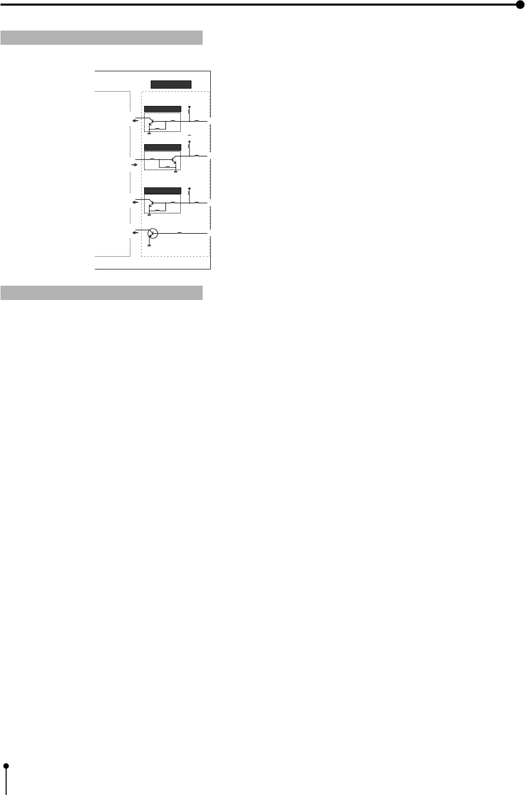
82
8. Printing Procedures (Special prints)
1 Circuit inside the VCP
Pin No. 6 REMOTE terminal
By sending the following remote control codes from Pin No. 6, the same functions as the wired remote
control (accessory) can be controlled.
Code
01
03
08
0A*
0C
0E*
12*
15*
17*
1C*
Function
LEFT SHIFT button
DOWN SHIFT button
PRINT Q’ty button (increase)
MENU button
PRINT Q’ty button(decrease)
SET button
PROG. (Program) button
FIELD/FRAME button
MEMORY button
MEMORY PAGE button
Code
02
04
09
0B*
0D
0F*
13*
16*
18*
1D*
Function
RIGHT SHIFT button
UP SHIFT button
CLEAR button
STOP button
PRINT button
COLOR ADJUST button
DISPLAY button
MONITOR button
In case of the codes with * mark, 5 words are sent.
22KΩ
22KΩ
10KΩ
100 Ω
DTC124EK DC5V
22KΩ
22KΩ
10KΩ
100 Ω
DTC124EK DC5V
1K
22KΩ
2.2KΩ
100 Ω
DTC124EK
DC5V
22KΩ
To VCP
To VCP
From VCP
To VCP
2 MEMORY
6 REMOTE
4 BUSY
User side
5 PRINT
} VCP
83
8. Printing Procedures (Special prints)
TIMING CHART
Input signal level : TTL
Input timing : 1 word 38.4 ms
Example: print code = 13=010011
External REMOTE 1 terminal on the rear panel
• The pin number on the positive pin is shown below.
1 External remote terminal Signal allocation Connector REMOTE 1
Pin No.
1
2
3
Function
Ground
MEMORY
BUSY
Description
Earth
Memory: When the signal becomes “LOW” from “HIGH”, the image is stored
in memory. (When the signal has been “LOW” for 60msec. or more, the image
is stored in memory.)
When “REMOTE BUSY” is set to “HIGH”
“HIGH” : The VCP cannot accept the remote signal.
“LOW” : The VCP can accept the remote signal.
The signal becomes “HIGH” in the following cases;
(1) During initialization after the VCP has been switched on
(2) For about 1 sec. after the INPUT SELECT switch has been set
(3) During displaying the menu screen
(4) When the image cannot be stored in memory
1.6 ms
0.4 ms
Input timing : Code : “0”
3.2 ms
0.4 ms
Input timing : Code : “1”
110010
132
1
3
2
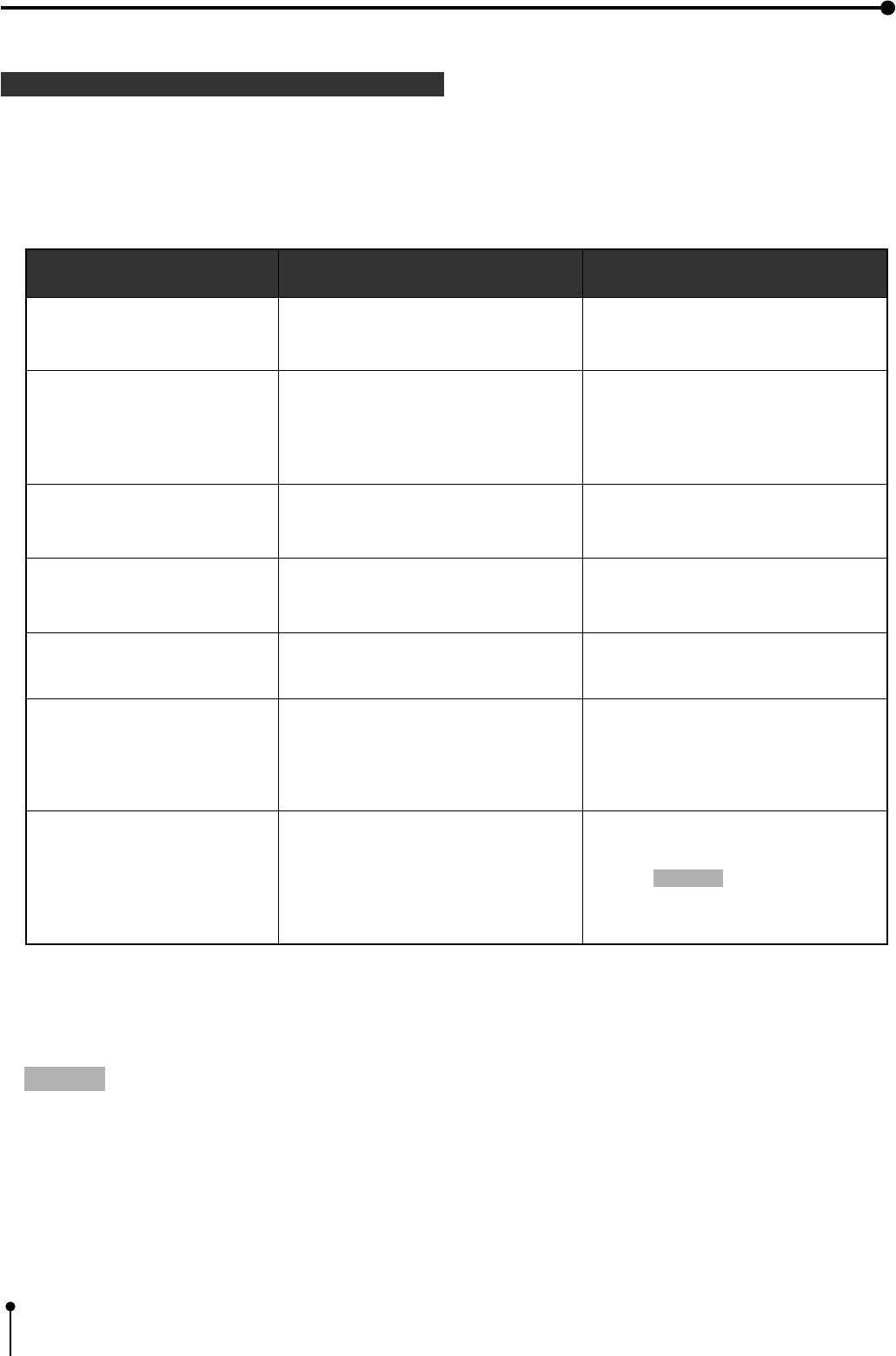
84
1 Error messages and countermeasures
9. Troubleshooting
1If for some reason printing is not possible or error occurs during printing, the error message will be displayed on the
monitor screen or LCD.
In this case, follow the procedure described below.
Error messages
DOOR OPEN
PAPER EMPTY
SHEET CARTRIDGE EMPTY
OVER HEAT
SHEET END
PAPER JAM J11
PAPER JAM J12
PAPER JAM J13
PAPER JAM J14
TECHNICAL ERROR J22
TECHNICAL ERROR J23
TECHNICAL ERROR J24
Causes
The printing unit is not
inserted correctly.
Paper is not set.
Paper is not set correctly.
Paper runs out during printing.
*Note : 1
The ink-cassette is not installed.
The temperature inside the unit
becomes too high.
The ink-sheet is used up.
Paper jamming occurs.
Other defects.
Countermeasures
Insert the printing unit until it is locked in
the unit.
Set the print paper correctly.
Refer to pages 7 - 8.
Install the ink-cassette.
Refer to page 8.
Wait until the message goes off.
*Note : 2
Replace the ink-sheet with a new one.
Refer to page 8.
Refer to “Overcoming paper jams”.
Press the MEMORY button for more 1
second while pressing the MONITOR
button. *Note : 3
If the status is not improved by carrying
out this measure, consult your dealer.
*Note : 1 In case of L-size printing, the image is not printed completely.
*Note : 2 When setting the continuous printing, the continuous printing is carried out after the
error message goes off.
*Note : 3 This is an operation for initialization. Make sure to press the MONITOR button first. If
the MEMORY button is pressed first, a new image will be stored in memory erasing any
previously stored image.
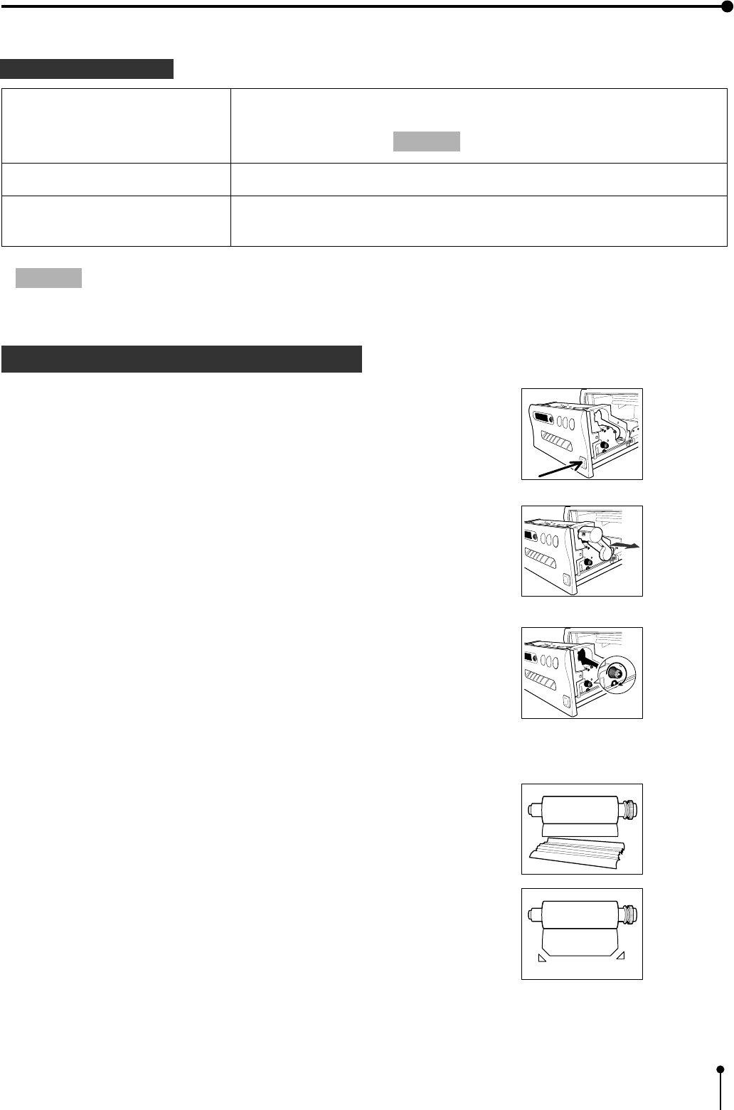
85
9. Troubleshooting
Other messages
MECHA INITIALIZE REQUEST
MECHA INITIALIZE
PRINT STOP
Indicated when the power is turned on after turning off during printing.
Press the MEMORY button for more than one second while pressing
the MONITOR button. *Note : 3
Indicated during initializing.
In the case of pressing the STOP button on the remote control during
printing, this unit is initialized. This message is indicated during initializing.
*Note : 3 This is an operation for initialization. Make sure to press the MONITOR button first. If the MEMORY
button is pressed first, a new image will be stored in memory erasing any previously stored image.
1 Overcoming paper jams
,Roll up the print paper completely.
1Press the OPEN button to pull out the printing unit.
2Remove the ink cassette.
3Turn the knob on the right side of the printing unit clockwise.
4Remove the print paper.
5Cut the defective part of print paper with scissors.
6Cut both edges of the print paper.
7Install the print paper. ( Refer to pages 7 - 8.)
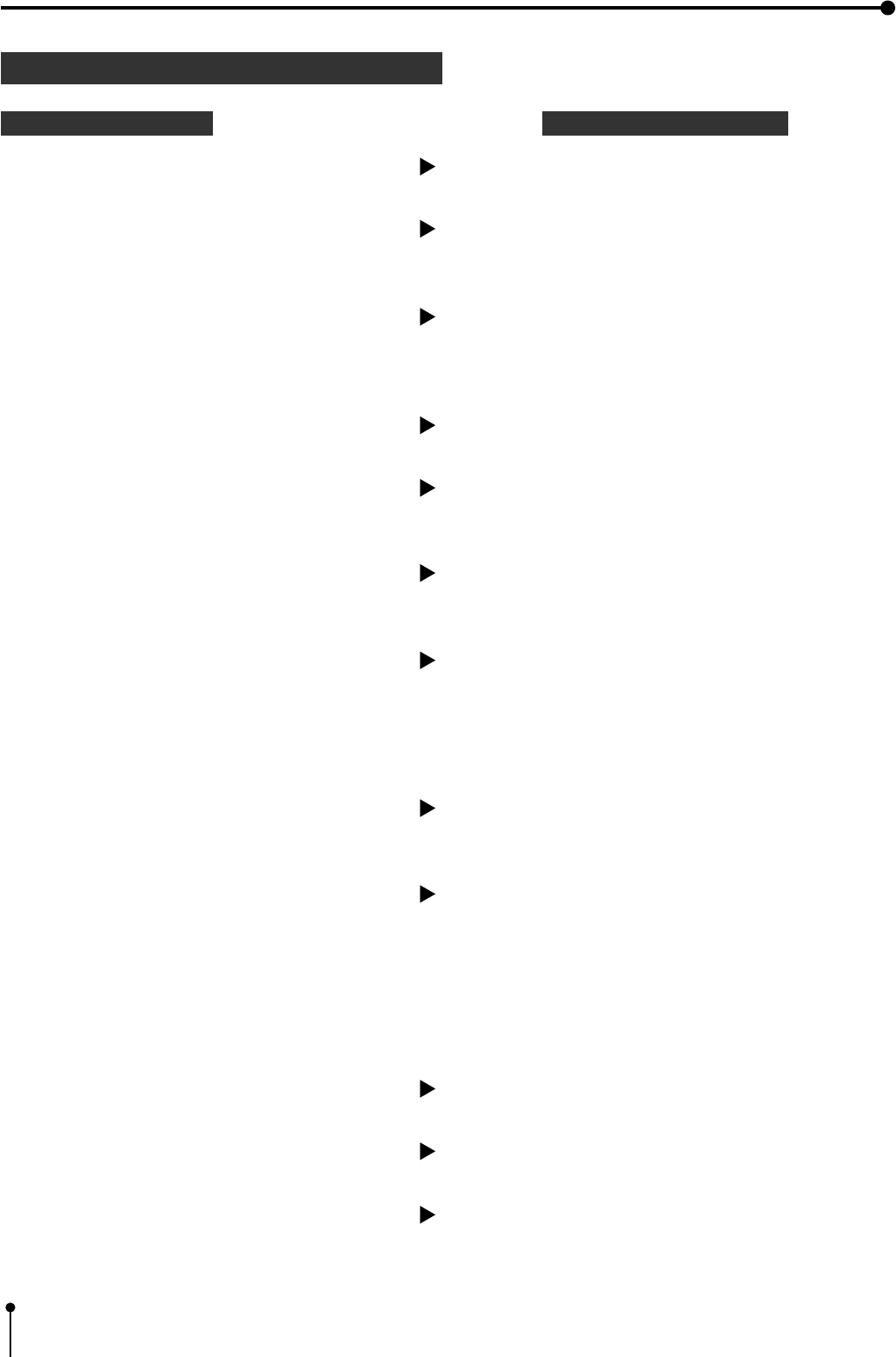
86
9. Troubleshooting
1 Before calling for service
Symptom Check and Remedy
1No power
1No image appears on the monitor
1The images on the monitor screen vibrates when
characters are indicated on the monitor screen or
“LIVE SEL” is set to “DIG”.
Refer to page 51.
1The image is not stored in memory.
1The image is not printed.
Is the power cord plug disconnected from the outlet?
After turning the power off, wait for approx. 2 minutes.
Then turn the power ON.
Are the sync.polarity of the monitor (SYNC : NEGA POSI), the
output level of the sync.signal (OUTPUT SYNC RGB) and the
RGB output sync. signal (RGB OUT) set correctly?
Are the video signal and sync. signal inputted to this unit?
→Connect the power cord plug to the outlet firmly.
→Check the current setting. Refer to pages 14-21.
→Check the connection. Refer to pages 14-21.
Is the input signal on the menu screen (INPUT: VIDEO, S-
VIDEO, RGB) selected correctly?
→Check the current setting. Refer to pages 29-30.
Is the image stored in memory displayed on the monitor screen?
→Press the MONITOR button to display the source image (LIVE).
Are the sync.polarity of the monitor (SYNC : NEGA POSI), the
output level of the sync.signal (OUTPUT SYNC RGB) and the
RGB output sync. signal (RGB OUT) set correctly?
→Check the current setting. Refer to pages 14-21.
Are the images being printed with full memorized memory page?
→Press the CLEAR button on the remote control after printing.
Then, store the image in the memory again.
Is the memory full in the status of “PAGE INC: OFF” or “PRINT
CLR :OFF”?
→Store the image in the memory after pressing the CLEAR button
on the remote control.
(According to the setting conditions, the image can be stored in
the memory by setting “PAGE INC” to “ON”, “PRINT&CLR” to
“ON” or pressing the PRINT button.)
Is the image stored in memory?
→Confirm that the image is stored in memory.
Is the print paper or ink sheet used up?
→Check the status.
Is the printing unit set correctly?
→Set the printing unit correctly.

87
9. Troubleshooting
Symptom Check and Remedy
1The stored image in the memory cannot be
enlarged to fill the maximum print area.
Is the SMALL size ink-sheet installed when selecting “S” in
“MODE : S/L”?
Or is the LARGE size ink-sheet installed when selecting “L” in
“MODE : S/L”?
→Check the current setting. Refer to pages 31 - 32.
1The color or picture quality is different between
the memorized image and the printed image.
1The image on the monitor screen printed paper is
not colored correctly.
(When the VIDEO signal without color burst
signal is inputted to the unit, the image on the
monitor screen or printed image becomes
monochrome or rainbow-like colored image.)
1The color or picture quality is different between
the image on the monitor screen and the printed
image. (When the color and picture quality are
same between the image stored in the memory
and the printed image.)
1The set comments do not appear on the print
paper.
1Wired remote control cannot be operated.
Is the paper size set to “N” in the size setting in SYSTEM menu?
→Set the size to “M” or “W”. Refer to page 51.
Is the S size image printed on the L size paper?
→Check the current setting. Refer to pages 31 - 32.
Is the print area set correctly in the USER SIZE ADJ?
→Check the setting of the print area. Refer to pages 52 - 53.
Is the color of the image stored in the memory adjusted?
→Adjust the color of the image stored in the memory with the
image adjustment display (COLOR ADJ). Refer to pages 45 -46.
Is the DCF set to “OFF”?
→Set the DCF to “OFF”. Refer to page 47.
Is the image on the monitor screen adjusted?
→Adjust the image on the monitor screen with “MON R-SUB”
and “MON B-SUB” in the SIGNAL ADJ menu in the signal
setting display. Refer to page 62.
Is the COMMENT set to “OFF”?
→Set the COMMENT to “COM”. Refer to page 50.
Is the COMMENT inputted?
→Input the COMMENT on the menu. Refer to page 56.
Is the plug of the remote control disconnected from its terminal
on the unit?
→Connect the plug of the remote control to the REMOTE
terminal on the unit.
Is the wired remote control for this unit (accessory) used?
→Use the remote control for this unit.
Is this unit operated through RS-232C interface?
→Set “KEY MASK” to “OFF” through RS-232C interface.
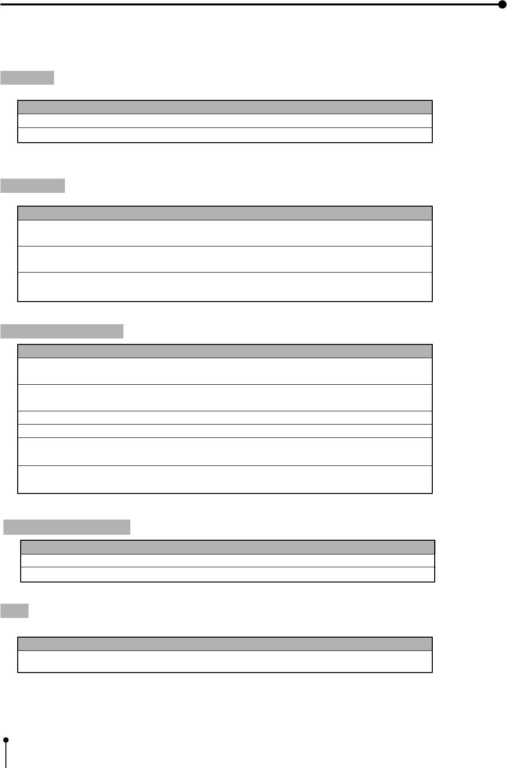
88
Product name
CK700S4P
CK700L4P
CK700SC
CK700LC
CK710SPC
CK710LPC
10. Options
The following types of ink sheets and print papers are sold separately.
Ink sheet
Print paper
Product name
PK700S
PK700L
Ink sheet size
S size
L size
No. of prints
200
130
Usage
For 3 color use
For 3 color use
Product name
CK700
K65H
K65HM
Print size
For S and L size
For S and L size
For S and L size
No. of prints
S size : Approx. 200
L size : Approx. 130
S size : Approx. 200
L size : Approx. 125
S size : Approx. 200
L size : Approx. 125
Usage
For 3 color use
For thermal printing
For thermal printing
Print-paper / Ink sheet
Ink sheet size
For S size
For L size
For S size
For L size
For S size
For L size
No. of prints
110
75
200
130
200
130
Usage
For 3 color use
(surface coated paper)
For 3 color use
(surface coated paper)
For 3 color use (sticker)
For 3 color use (sticker)
For 3 color use
(16-division pre-cut sticker)
For 3 color use
(16-division pre-cut sticker)
Ink sheet / Ink cassette
Ink sheet size
For S size
For L size
No. of prints
200
130
Usage
For 3 color use
For 3 color use
Tray
Product name
TR700L
Usage
For receiving printed paper
Product name
PKC700S
PKC700L
89
11. Specifications
Class
Model
Printing method
Print quality
Printing time
Ink sheet
Print paper
Supply method
Input terminal
Output terminal
Input/ Output terminal
Input frequency
Power supply
Power consumption
Installation conditions
Outside dimensions
Weight
Colour Video Copy Processor
CP700E
Sublimation Dye Thermal
3 colour faces progressive printing ( yellow, magenta and cyan)
Dot resolution max.1216 x 600 pixels
Number of grades 256 for each color
Approx.38 sec./ sheet (L size high speed mode)
Approx.51 sec./ sheet (L size standard speed mode)
Approx.22 sec./ sheet (S size high speed mode)
Approx.29 sec./ sheet (S size standard speed mode)
Special cartridge method
Special roll paper L size 162 x 110 mm
Printing area Wide mode 130 x 98 mm
Middle mode 123 x 92 mm
Narrow mode 120 x 90 mm
Special roll paper S size 110 x 107 mm
Printing area Wide mode 100 x 75 mm
Middle mode 94 x 70 mm
Narrow mode 92 x 69 mm
Automatic
RGB analog (4 BNC type connectors)
Composite video (1 BNC type connectors)
S-VIDEO (1 S-VIDEO terminal)
RGB analog (4 BNC type connectors)
Composite video (1 BNC type connectors)
S-VIDEO (1 S-VIDEO terminal)
RS-232C interface (D-SUB 25 pin)
Remote terminal ( Mini DIN 8 pin/ Stereo jack )
H frequency 15.625 kHz
V frequency 50 Hz
AC 220-240V, 50Hz
1.3A during printing
Temperature: 5°C- 40°C Humidity: 20 -80 % (no dewing)
Operation altitude : Horizontal ±5°
280 (W ) x 150 (H) x 399(D) mm
14.5 kg
1Design and specifications are subject to change without notice.
Mitsubishi Electric Europe B.V.
UK Branch
Travellers Lane, Hatfield, Herts. AL10 8XB, England, U.K.
Phone (1) 707 276100 FAX (1) 707 278755
German Branch
Gothaer Strasse 8, Postfach 1548, 40880 Ratingen 1, Germany
Phone (2102) 4860 FAX (2102) 486-732
French Branch
25, Boulevard des Bouvets - 92741 NANTERRE cedex
Phone (01) 55.68.55.00 FAX (01) 55.68.57.31
Italian Branch
Centro Direzionale Colleoni, Palazzo Perseo-Ingresso 2,
Via Paracelso 12, 20041 Agrate Brianza, (Milano) Italy
Phone (039) 60531 FAX (039) 6057694
Benelux Branch
Nijverheidsweg 23 A, 3641 RP. Postbus 222, 3640 AE Mijdrecht
Phone 02972-82461 FAX 02972-83936
Spanish Branch (Barcelona)
Sucursal en españa
Polígono Industrial “Can Magí”, Calle Joan Bucallà 2-4,
Apartado de Correos 420, 08190 Sant Cugat del Vallês,
Barcelona, Spaín
Phone (3) 589-3900 FAX (3) 589-4448
Manufactured by Mitsubishi Electric Corporation
1 Zusho Baba, Nagaokakyo-City, Kyoto Japan
Made from recycled paper
PRINTED IN JAPAN 871C952H4
