Mitsubishi Electronics Digital Recorder Dx Tl950E Users Manual 1) Beggining(p1 9)
DX-TL950E to the manual 263a9159-98c8-4031-9838-96f1b79c67d1
2015-02-09
: Mitsubishi-Electronics Mitsubishi-Electronics-Digital-Recorder-Dx-Tl950E-Users-Manual-556598 mitsubishi-electronics-digital-recorder-dx-tl950e-users-manual-556598 mitsubishi-electronics pdf
Open the PDF directly: View PDF ![]() .
.
Page Count: 90

1
ENGLISH
OTHERS
DIGITAL RECORDER
INSTALLATION AND
OPERATION MANUAL
MODEL
DX-TL950E
THIS INSTRUCTION MANUAL IS IMPORTANT TO YOU. PLEASE READ IT BEFORE USING YOUR DIGITAL RECORDER.
SLD Security & Communications
The Old Forge, Ockham Lane, Ockham, Surrey GU23 6PH England
Phone +44.1483225633 · Fax +44.1483225634
sales@sld.co.uk · www.sld.co.uk

2
••••••••••••••••••••••••••••••••••••••••••••••••••••••••••••••••••••••••••••••••••••••••••••••••••••••••••••••••••••••••••••••••••••••••••••
Network
• From the personal computer connected to Internet using the Microsoft Internet Explorer, the image screen
such as live images, search and playback image can be displayed. ( see pages 77-82)
• LAN software for applications in grate variety
Optional software with high-quality communication functions.
Built-in duplex 9 channel multiplexer
• The screen mode can be switched on the monitor such as single screen, split4 screen, split9 screen and
sequential screen, split4 sequential screen. ( see page 36)
• The unit is equipped with the 2 type-output connector to display the different mode split screen on the each of
different monitors. ( see page 37)
• Convenient simultaneous recording-playback function. Live picture from all cameras can be recorded con-
tinuously while the recording of desired camera is played back.
• The unit can neither record nor display on the monitor the camera image legally prohibited.
Recording
• Recording rate 50 pps ( picture per second )
50 pps recording which is becoming the industrial standard is available on the 9 ch unit. 3 pps recording per
each camera is also available even using 9 cameras.
• Built-in 250GB HDD or higher. Furthermore 2 HDDs can be built in the unit by installing 1 additional HDD.
• Various record setting
Recording interval and picture quality of each camera can be set individually to both normal recording and
alarm recording. ( see pages 41-43)
• Flexible alarm recording
Any camera number for alarm recording of 3 modes such as Alarm Channel, Alarm Plus and Alarm25 can be
assigned. 4 triggers are also selectable out of various combination such as external alarm input and motion
detection, external alarm input or motion detection, only external alarm input or only motion detection.
( see pages 41-43)
• Partition recording
Alarm images can be recorded in a designated area within HDD to keep alarm images longer term than normal
recording. The partition area can be set from 10% to 90% of HDD capacity. ( see page 75)
• Mirror recording
Mirror recording for prevention against a data loss in case of HDD crash. ( see pages 74,75)
When using a MIRRORING function, two sets of HDD are required. It does not function in one HDD.
Please consult with the retailer, when you add HDD.
• Built-in motion detection
It is available the high-fidelity detection setting by the detection area of 192 (12 x 16) dots.
( see pages 39,40)
• Wavelet compression
Wavelet method with compression of higher-rate than JPEG.
• 1ch PCM audio recording. ( see page 48)
Features

ENGLISH
3
••••••••••••••••••••••••••••••••••••••••••••••••••••••••••••••••••••••••••••••••••••••••••••••••••••••••••••••••••••••••••••••• Beginning
Ease of use
• Auto set-up
By selecting only the recording period of 24, 96 or 168 hrs. and 14 or 30 days, the unit assigns automatically
recording interval and picture grade for all channels and other menu settings are set to the default.
( see pages 17,18)
Microsoft is either registered trademarks or trademarks of Microsoft Corporation in the United States
and/or other countries.
Compact FlashTM is a trademark of SanDisk Corporation.
Storage capacity is indicated in gigabytes (GB). (1GB = 1000 x 1000 x 1000 bytes.)

4
••••••••••••••••••••••••••••••••••••••••••••••••••••••••••••••••••••••••••••••••••••••••••••••••••••••••••••••••••••••••••••••••••••••••••••
NEVER TOUCH OR INSERT ANY OBJECT INSIDE THE UNIT
Touching the inside of the cabinet or inserting foreign objects of any kind not only creates a safety hazard
but can also cause extensive damage.
PROTECT THE POWER CORD
Damage to the power cord may cause fire or shock hazard. If the mains cord is damaged, switch off the
mains outlet and carefully unplug the cord by holding the mains plug.
UNPLUG THE POWER CORD DURING A LONG ABSENCE
Turn off the power and unplug the power cord during a long absence.
MAINTAIN GOOD VENTILATION
Do not obstruct the many ventilation holes on the unit. For maximum ventilation, leave some space around
the unit and place the unit on a hard level surface only, and ensure it is not covered during use. Heavy objects
should never be placed on the unit.
WHEN NOT IN USE
When not in use always turn OFF the MAIN switch.
CABINET CARE
Never use petroleum-based cleaners. Clean with a soft cloth moistened with soap and water and wipe dry.
PVC cables or leads should not be left in contact with the cabinet surface for long periods.
INSTALLATION LOCATION
For excellent performance and lasting reliability install in a location that is:-
1. Well ventilated, out of direct sunlight and away from direct heat.
2. A solid vibration-free surface.
3. Free from high humidity, excessive dust and away from magnetic fields.
4. Please ensure that the ventilation fan located on the unit’s back panel is not blocked.
UNSUITABLE LOCATIONS
Placing the unit in the following places might shorten the product life:
•Extremely cold places, such as refrigerated warehouses and ice houses
•Places where excessive hydrogen sulfide is likely to be generated, such as hot-springs areas
•Places or locations with salt air environment.
WARNING: TO PREVENT FIRE OR SHOCK HAZARD, DO NOT EXPOSE THIS APPARATUS TO RAIN OR
MOISTURE. THIS APPARATUS MUST BE GROUNDED.
HEAVY OBJECTS SHOULD NEVER BE PLACED ON THE UNIT (E.G., TV)
Caution and care

ENGLISH
5
••••••••••••••••••••••••••••••••••••••••••••••••••••••••••••••••••••••••••••••••••••••••••••••••••••••••••••••••••••••••••••••• Beginning
•This unit has a built-in hard disk, which is a precision device. Please handle this unit with sufficient
care.
•Do not subject this unit to vibrations or shocks. This may cause trouble specially when the unit is
switched on or when the hard disk is being accessed, and sufficient care is required.
•Do not disconnect the power plug while the unit is switched on or while recording or playing.
•For early detection of faults, we recommend that you request inspection once a year.
•Please do not move the unit at least one minute after turning off the power.
•The hard disk and cooling fan are not permanent items and will need replacement with time.
When operated in an ambient temperature of 25°C, it is recommended that both the hard disk and fan
be replaced after 30,000 hours.
(This figure is only a guide, and should not be taken as a guaranteed lifespan of the products. Use the
“ELAPSED TIME” on the <INFORMATION/SERVICE> screen as a guide to performing checkups.)
This Unit complies with the requirements of the EC Directive 89/336/EEC, “EMC Directive” and 73/23/EEC,
“Low Voltage Directive”, as amended by Directive 93/68/EEC. The requirements for the susceptibility
according to EN 55024 and the requirements for interference according to EN 55022 are observed for the
operation on residential areas, business, light industrial premises and in small scale enterprises, inside as
well as outside of the building. All places of operation are characterised by their connection to the public
low voltage power supply system. This unit is manufactured in accordance with EN 60950.
There may be cases when the unit’s built-in MOTION DETECTION function does not operate properly
due to external condition or video input signal or other factors.
MAINS LEAD CONNECTION
The mains lead on this Unit is fitted with a non-rewireable mains plug, incorporating a 5A fuse. If you
need to replace the fuse, use a 5A fuse approved by BSI or ASTA to BS 1362, ensuring you refit the
fuse cover. If the mains plug is not suitable for the sockets in your home, and you require to remove
the plug, remove the fuse, cut off the plug then dispose of the plug immediately, to avoid a possible
electric shock hazard. To refit a new plug, follow these instructions; Green-and-yellow: Earth, Blue:
Neutral and Brown: Live. As the colours in the mains lead of this Unit may not correspond with the
coloured markings identifying the terminals in your plug, proceed as follows.
•The wire which is coloured green-and-yellow must be connected to the terminal in the plug which is
marked by the letter E or by the safety earth symbol or coloured green or green-and-yellow.
•The wire which is coloured blue must be connected to the terminal which is marked with the letter N or
coloured black.
•The wire which is coloured brown must be connected to the terminal which is marked with the letter L or
coloured red.
The user will not be indemnified for problems (e.g., recording failure or playback failure) that occur with
either the unit or a connected device during operation. It is recommended that backups of important
recordings are made regularly as a precaution against possible breakdowns and accidents.
Recordable time and product warranty
Continuous recordable time and the estimated time displayed on the menu screen is the continuous
recordable time when operating this unit and is not the product warranty period. Furthermore, it is not
the period that guarantees life time at the unit.

6
••••••••••••••••••••••••••••••••••••••••••••••••••••••••••••••••••••••••••••••••••••••••••••••••••••••••••••••••••••••••••••••••••••••••••••
Features ................................................................. 2,3
Caution and care ................................................... 4,5
Contents................................................................. 6,7
Flowchart ............................................................... 8,9
Flowchart for connection and settings ............................. 8,9
Major operations and their functions ..............10-14
Front View .................................................................... 10,11
Front View (Inside of the door) ..................................... 11,12
Inserting/Ejecting Compact Flash Card ............................ 11
Rear View..................................................................... 13,14
Connections ...................................................... 15,16
Connecting to CCTV camera, monitor, sensor ................. 15
EMERGENCY/ALARM IN/REC/
CLOCK ADJ Input terminal ............. 15
MODE OUT1 - 5 Output terminal ...................................... 15
CALL OUT Output terminal ............................................... 15
Alarm Recording Connection ............................................ 16
Connecting with analog video recorder ............................. 16
AUTO SET UP .................................................... 17,18
AUTO SET UP ............................................................. 17,18
Initial settings ......................................................... 18
INITIALIZATION ................................................................ 18
HDD SETTING ............................................................ 18
INITIALIZATION .......................................................... 18
Basic Operations...............................................19-25
Multiplexer functions ......................................................... 19
Multiplexer buttons ...................................................... 19
Menu settings ............................................................... 19-21
To return to the normal screen from a menu screen ... 20
DAYLIGHT SAVING/DAYLIGHT SETTING ................. 20
TIME DATE ADJUST ............................................. 20,21
Present time display .................................................... 21
Recorded capacity display function ............................ 21
Basic manual recording ............................................... 21-23
Setting the recording interval and recording
picture quality for normal recording ................... 22,23
Basic playback ............................................................. 23,24
Basic search ................................................................ 24,25
TIME DATE SEARCH ............................................ 24,25
LANGUAGE SELECTION ................................................. 25
Menu functions..................................................26-31
MENU SETTING .......................................................... 26-30
COPY MENU .................................................................... 31
SEARCH SELECTION MENU .......................................... 31
<TIME DATE/DISPLAY SETTINGS>..................32-34
TIME DATE ADJUST ........................................................ 32
DISPLAY MODE ............................................................... 32
CLOCK LOCATION SETTING .......................................... 32
CAMERA DISPLAY ........................................................... 32
CAMERA TITLE/MEMO SETTING .............................. 32,33
DUPLEX MODE DISPLAY ................................................ 34
<MPX DISPLAY SETTINGS> ............................. 35-38
Multiplexer function related button
operations/operation table ............ 35
Camera number button operations ............................. 35
SPLIT/SEQUENCE button operations ........................ 35
ZOOM button operations ............................................ 35
The function of the SPLIT/SEQUENCE button,
ZOOM button, and camera number buttons ........... 36
MPX DISPLAY SETTINGS ............................................... 37
SPLIT4 SCREEN SETTING ............................................. 37
SPLIT9 SCREEN SETTING ........................................ 37,38
SEQUENCE SETTING ..................................................... 38
INTERLACE ...................................................................... 38
<MOTION DETECTION SETTINGS> ................. 39,40
SELECTION CAMERA NUMBER ..................................... 39
DETECTION MASK SETTING ......................................... 39
SENSITIVITY .................................................................... 40
MOTION THRESHOLD..................................................... 40
TEST MODE ..................................................................... 40
<RECORD SETTINGS> .....................................41-43
Settings concerning normal recording
and alarm recording ............ 41
Recording mode settings for normal recording
and alarm recording ....... 41,42
ALARM REC DURATION .................................................. 43
PRE ALARM REC ............................................................. 43
MOTION DET REC ........................................................... 43
<TIMER PROGRAM SETTINGS> ......................44-46
TIMER PROGRAM SETTINGS ........................................ 44
TIMER PROGRAM ...................................................... 44,45
Structure of the <TIMER PROGRAM> screen ....... 44,45
HOLIDAY SETTING .......................................................... 46
Recording mode settings A ~ D
for normal recording/alarm recording ............ 46
MOTION DET REC ........................................................... 46
ALARM REC DURATION .................................................. 46
Overlapping Timer settings ......................................... 46
<INITIAL SET UP/INFORMATION> ...................47-58
HDD SETTINGS .......................................................... 47,48
HDD REPEAT REC MAIN/HDD REPEAT REC SUB .. 47
HDD REPEAT PLAY ................................................... 47
IM-CHECK PLAY ........................................................ 47
SEQUENTIAL PLAY ................................................... 48
AUDIO RECORDING ........................................................ 48
REAR TERMINAL SETTINGS ..................................... 49-51
MODE OUT 1 ~ MODE OUT 5 ................................... 49
KEY SOUND ............................................................... 49
BUZZER ................................................................. 49,50
REMAIN HDD ............................................................. 50
CALL OUT SETTINGS ........................................... 50,51
HDD MAIN REMAIN/HDD SUB REMAIN ......... 50,51
HDD MAIN FULL/HDD SUB FULL......................... 51
EMERGENCY REC DURATION ................................. 51
COMMUNICATION PORT SETTINGS ........................ 51-54
RS-232C ................................................................ 51,52
MODE .................................................................... 51
SETTINGS ............................................................. 52
ETHERNET ............................................................ 52-54
E-MAIL ADDRESS ................................................. 52
SERVICE PORT SETTING .................................... 53
ALARM NOTIFICATION SETTING ................... 53,54
INFORMATION/SERVICE ........................................... 54-56
HDD INFORMATION/CFC INFORMATION ................ 54
WARNING LOG LIST ............................................. 54,55
RESET TO FACTORY SETTINGS ............................. 55
DATA CLEAR ......................................................... 55,56
PASSWORD ................................................................ 56-58
SIMPLE LOCK ............................................................ 56
PASSWORD LOCK ................................................ 56-58
LANGUAGE SELECTION ................................................. 58
<QUICK SETTINGS> .............................................. 59
QUICK SETTINGS ............................................................ 59
To update menu settings of this unit ........................... 59
To save menu settings of this unit
to a Compact Flash Card ............................ 59
Contents
ENGLISH
7
••••••••••••••••••••••••••••••••••••••••••••••••••••••••••••••••••••••••••••••••••••••••••••••••••••••••••••••••••••••••••••••• Beginning
Operation examples ..........................................60-63
Operation example 1 ......................................................... 60
Operation example 2 .................................................... 61,62
Operation example 3 .................................................... 62,63
Various recordings................................................. 64
PRE ALARM RECORDINGS ............................................ 64
EMERGENCY RECORDINGS.......................................... 64
Various playback functions.............................. 65,66
Playing still frames ............................................................ 65
Shuttle viewing/direct shuttle viewing ............................... 65
Shuttle hold ....................................................................... 65
Frame-by-frame playback ................................................. 65
Reverse playback ............................................................. 65
High-speed fast-forward/high-speed rewind ..................... 65
Changing playback intervals ........................................ 65,66
Simultaneous playback during recording .......................... 66
Various search...................................................67-71
SEARCH SELECTION ...................................................... 67
SEARCH TYPE ........................................................... 67
SELECTION CAMERA NUMBER ............................... 67
DATE/TIME ................................................................. 67
PLAYBACK DEVICE ................................................... 67
TIME DATE SEARCH ....................................................... 67
INDEX SEARCH/ALARM INDEX SEARCH ................. 68,69
ALARM SKIP SEARCH................................................ 69,70
ALARM LIST SEARCH ................................................ 70,71
START/END SEARCH ...................................................... 71
Making Copy/Restore ....................................... 72,73
Making Copy/Restore .................................................. 72,73
Copying from unit to videotape ......................................... 73
Other convenient functions .............................74-76
Power failure compensation circuit ................................... 74
Power failure reset recording ............................................ 74
Log function for when power failure occurs while
the unit is in operation or the MAIN switch
on the rear of the unit is turned OFF ................ 74
RESET button ................................................................... 74
HDD SETTING ............................................................. 74,75
MIRRORING .......................................................... 74,75
PARTITION/PARTITION SIZE .................................... 75
COVERT CAMERA SETTING .......................................... 76
ALARM DISPLAY ........................................................ 76
Communications by Web Browser ..................77-82
Communications by Web Browser ............................... 77-82
The personal computer product requirements ............ 77
Connections ................................................................ 77
AUTHENTICATION ................................................ 77,78
Welcome ................................................................ 78-82
Live monitor ...................................................... 78,79
Playback ........................................................... 79,80
Time Search ........................................................... 80
Alarm Search ......................................................... 80
Index Search .......................................................... 80
User maintenance ............................................. 80,81
Log out ................................................................... 81
Change log in user ............................................ 81,82
Recording time table......................................... 83,84
Continuous recording time table .................................. 83,84
HDD continuous recording time (for 250GB drive) ....... 83
Without Audio recording ......................................... 83
With Audio recording .............................................. 83
Compact Flash Card continuous
recording time (for 64MB) ...................... 84
Without Audio recording ......................................... 84
With Audio recording .............................................. 84
Troubleshooting ................................................ 85,86
Warnings and CALL OUT output ..................... 87,88
Warnings and their appropriate countermeasures .........
87,88
Glossary .................................................................. 89
Glossary ............................................................................ 89
Relation of recording operation to the number of
cameras and recording interval settings ........... 89
Specifications ......................................................... 90
How to read this manual
• Viewing displays
(Refer to this information when operating)
Reference information concerning operation is
described.
(Caution required)
Cautionary items concerning operation are
described.
(See reference page)
Reference item and page number are indicated.
INFORMATION
(Reference)
Other reference information is described.
• Finding desired information
There is an index on the each right page of this
manual. There is also “Contents” at the beginning
of this manual. In addition, reference pages are
indicated throughout this manual.
• Troubleshooting
Read Troubleshooting (pages 85,86) for possible
remedies to the problem.
•••••••••••••••••••••••••••••••••••••••••••••••••••••••••••••••••••••••••••••••••••••••••••••••••••••••••••••••••••••••••••••••••••••••••••
8
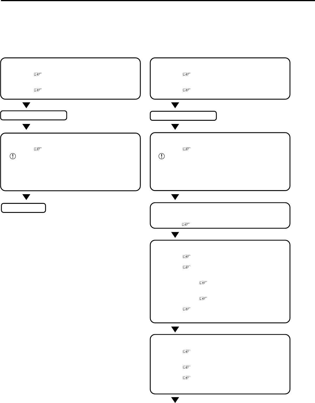
Flowchart
■ Flowchart for connection and settings
Installation example :
This is an example operational flowchart of the following : making connections at the rear of the terminal ; setting
HDD mode to PARTITION ; making default settings ; making an Alarm recording with Timer mode ; searching
recorded data with ALARM LIST SEARCH ; using playback, and copying to a Compact Flash Card.
Connection to the terminals on the back
• Connection to the terminals on the back.
See “■ Connecting to CCTV camera, monitor,
sensor”, page 15.
• Connection to the alarm recording.
See “n Alarm Recording Connection”,
page 16 and “n Rear View” , pages 13,14.
The unit is booted
AUTO SET UP
• Setting the auto set up.
See “■ AUTO SET UP”, pages 17,18.
Only when the unit is turned on for the first time, the
<AUTO SET UP> screen is displayed automatically. It is not
automatically displayed after next time.
Selecting the “YES” in “PERFORM AUTO SET
UP?” setting.
Recording
Connection to the terminals on the back
• Connection to the terminals on the back.
See “■ Connecting to CCTV camera, monitor,
sensor”, page 15.
• Connection to the alarm recording.
See “n Alarm Recording Connection”,
page 16 and “n Rear View” , pages 13,14.
The unit is booted
AUTO SET UP
• Setting the auto set up.
See “■ AUTO SET UP”, pages 17,18.
Only when the unit is turned on for the first time, the
<AUTO SET UP> screen is displayed automatically. It is not
automatically displayed after next time.
Selecting the “NO” in “PERFORM AUTO SET
UP?” setting.
Making the HDD REC SETTING
• Setting the PARTITION. “♦ PARTITION/PARTITION SIZE”
default settings “NORMAL” } }
} }
} “PARTITION”.
See “♦ PARTITION/PARTITION SIZE”, page 75.
Changing the initial menu settings
• Setting the language.
See “■ LANGUAGE SELECTION”, page 25.
• Setting the present time and screen display.
See “<TIME DATE/DISPLAY SETTINGS>”,
pages 32-34.
• Setting the present time.
See “♦ TIME DATE ADJUST”, pages
20,21.
• Setting the display mode.
See “■ DISPLAY MODE”, page 32.
• Setting the audio recording.
See “■ AUDIO RECORDING”, page 48 and
“■ Continuous recording time table”, pages
83,84.
Setting the HDD (hard disk drive) mode
• Setting the repeat recording.
See “♦ HDD REPEAT REC MAIN/HDD
REPEAT REC SUB”, page 47.
• Setting the remain HDD capacity.
See “♦ REMAIN HDD”, page 50.
• Setting the call out.
See “• HDD MAIN REMAIN/HDD SUB
REMAIN”, pages 50,51 and “• HDD MAIN FULL/
HDD SUB FULL”, page 51.
ENGLISH
•••••••••••••••••••••••••••••••••••••••••••••••••••••••••••••••••••••••••••••••••••••••••••••••••••••••••••••••••••••••••••••• Flowchart
9
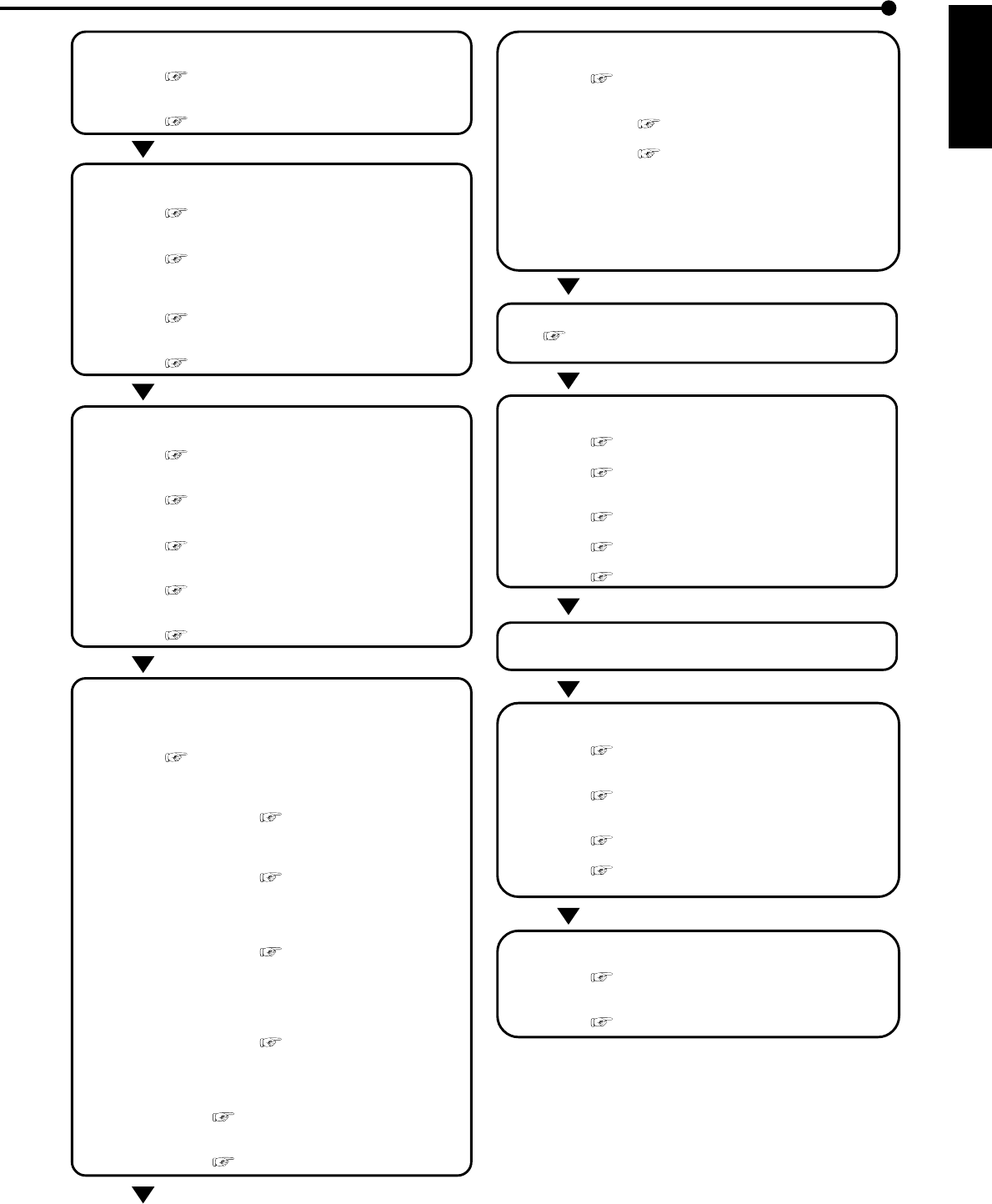
Setting the timer recording (continued)
• Setting the timer program mode.
See “<TIMER PROGRAM SETTINGS>”,
pages 44-46.
• Setting the holiday.
See “■ HOLIDAY SETTING”, page 46.
• Selecting the timer program.
See “♦ Structure of the <TIMER
PROGRAM> screen”, pages 44,45.
• Setting the timer recording.
• Selecting the day.
• Selecting the start time.
• Selecting the end time.
• Selecting the recording mode.
• Selecting the motion detection mode.
Timer recording is executed/completed
See “■ Warnings and their appropriate
countermeasures”, pages 87,88.
Searching the recorded data
• Setting the device of searching.
See “♦ PLAYBACK DEVICE”, page 67.
• Selecting the camera number of searching.
See “♦ SELECTION CAMERA NUMBER”,
page 67.
• Selecting the search mode.
See “♦ SEARCH TYPE”, page 67.
• Setting the alarm list search.
See “■ ALARM LIST SEARCH”, pages 70,71.
• Setting the search time and date of alarm list.
See “♦ DATE/TIME”, page 67.
The search is completed/The search result
is displayed
Playback the search result
• Selecting the camera number of playback.
See “<MPX DISPLAY SETTINGS>”, pages 35-
38.
• Selecting the sequence screen.
See “♦ SPLIT/SEQUENCE button
operations”, page 35.
• Playback See “■ Basic playback”, pages 23,24.
• Selecting the speed of playback.
See “Various playback functions”, pages 65,
66.
Copy the data
• Inserting the Compact Flash Card.
See “■ Inserting/Ejecting Compact Flash
Card”, page 11.
• Setting the copy function.
See “Making Copy/Restore”, pages 72,73.
Changing the multiplexer function
• Changing the split4 , split9 screen settings.
See “■ SPLIT4 SCREEN SETTING”, page 37,
“■ SPLIT9 SCREEN SETTING”, pages 37,38.
• Changing the sequence setting.
See “■ SEQUENCE SETTING”, page 38.
Setting other various functions
• Changing the display mode.
See “■ CLOCK LOCATION SETTING”, page
32 and “■ DUPLEX MODE DISPLAY”, page 34.
• Setting the camera title/memo.
See “■ CAMERA TITLE/MEMO SETTING”,
pages 32,33 and “■ CAMERA DISPLAY”, page
32.
• Setting to output signals of the unit status.
See “♦ MODE OUT 1 ~ MODE OUT 5”, page
49.
• Setting the buzzer.
See “♦ BUZZER”, pages 49,50.
Setting the motion detection
• Selecting the camera number.
See “■ SELECTION CAMERA NUMBER”,
page 39.
• Setting the active/inactive of detection function.
See “■ Recording mode settings for normal
recording and alarm recording”, pages 41,42.
• Setting the detection areas.
See “■ DETECTION MASK SETTING”, page
39.
• Setting the sensitivity.
See “■ SENSITIVITY”, page 40.
• Setting the minimum number of dots for starting the
motion detection operation.
See “■ MOTION THRESHOLD”, page 40.
Setting the timer recording
Setting the recording
• Selecting the normal & alarm recording or pre-alarm
recording. See “■ Recording mode settings A ~ D for
normal recording/alarm recording”, page 46.
• Setting the recording mode.
• Setting the motion detection recording.
See “■ MOTION DET REC”,
page 46.
• Selecting the camera selection during
the alarm recording.
See “■ Recording mode
settings for normal recording and
alarm recording”, pages 41,42.
• Setting the interval/picture grade for
normal recording.
See “♦ Setting the recording
interval and recording picture
quality for normal recording”,
pages 22,23.
• Setting the interval/picture grade for
alarm recording.
See “♦ Setting the recording
interval and recording picture
quality for normal recording”,
pages 22,23.
• Setting the duration of alarm recording.
See “■ ALARM REC DURATION”,
page 46.
• Setting the duration of pre-alarm recording.
See “■ PRE ALARM REC”, page 43.
10
••••••••••••••••••••••••••••••••••••••••••••••••••••••••••••••••••••••••••••••••••••••••••••••••••••••••••••••••••••••••••••••••••••••••••••
Multplex
&
Record
Digital
TIMER
ENTER/
FF
CLEAR/
REW
M-DET
PRE ALARM LOCK
EMERGENCY
SPLIT/
SEQUENCE ZOOM / 0
ACCESS
REC/STOP
DIGITAL RECORDER DX-TL950
POWER
56789
1234
OUTPUT
A/B
12 16151413
89
7
6
5
1234
COM
11
OUTPUT B
10
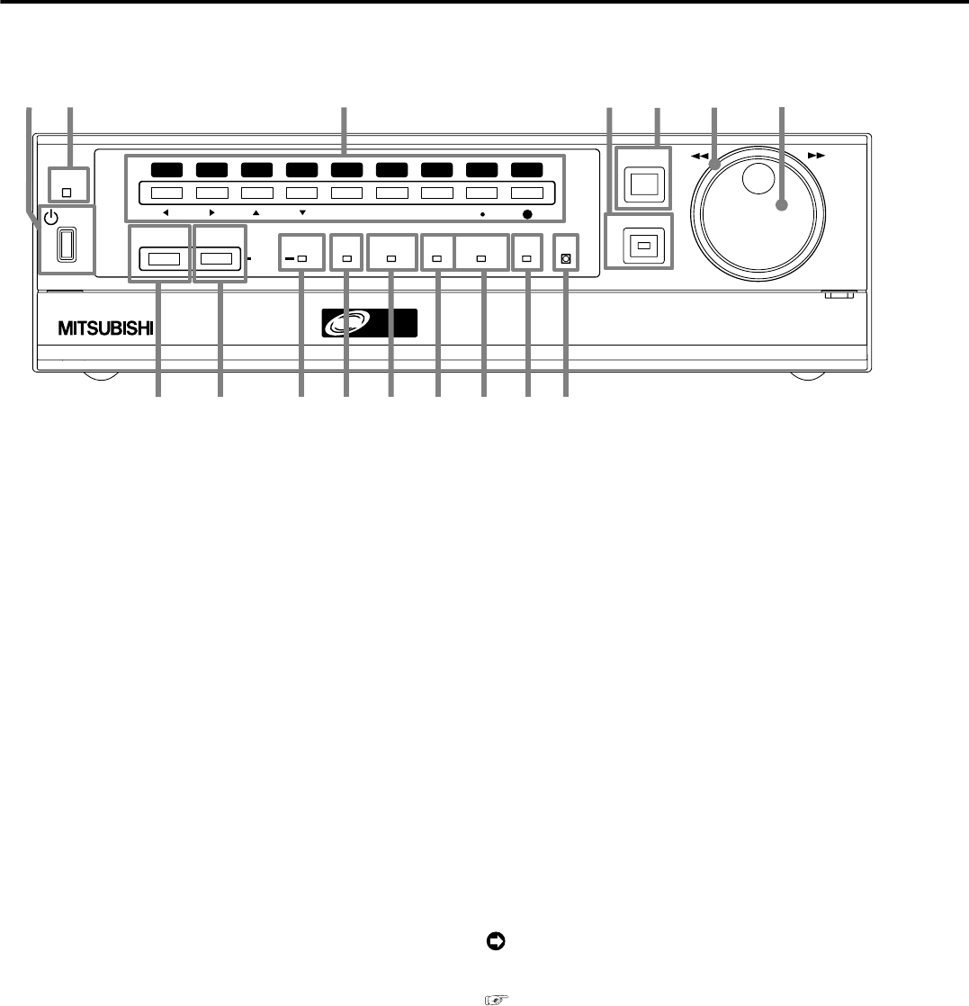
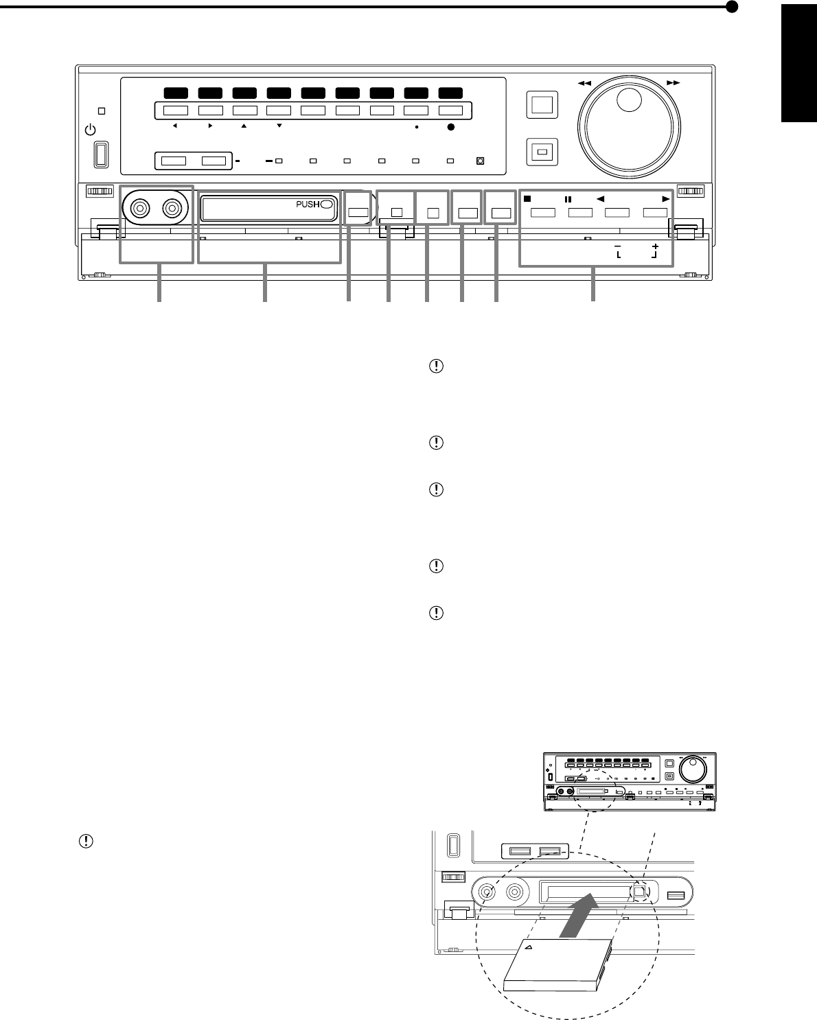
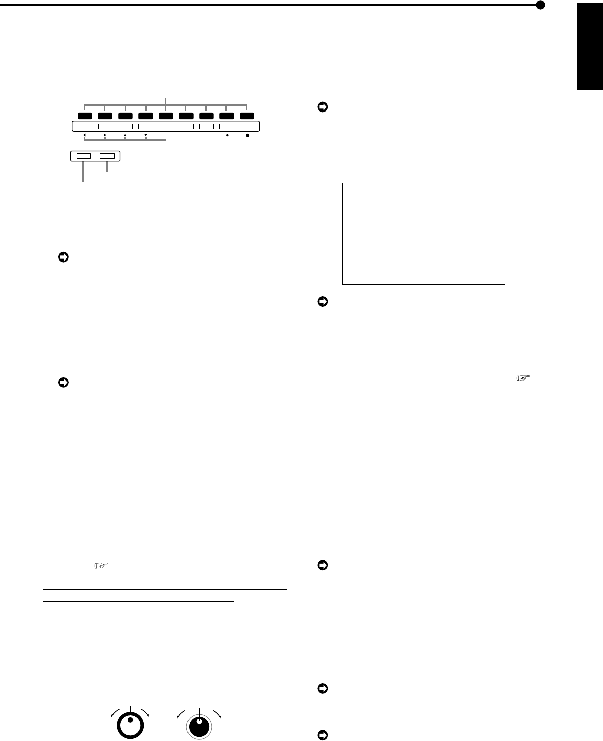
1. POWER button
When pressing this button while the MAIN switch on
the rear of this unit is set to ON, the power turns on
and the button lights. When the button is pressed
again, the unit will be in stand-by and the light will
turn off. When the unit is in operational transition
such as booting, the button will flash and other op-
erations are not accepted.
2. ACCESS indicator
Illuminates during access to hard disk drive or Com-
pact Flash Card.
3. Camera number buttons (1 to 9)
Press the button to display the image from the cam-
era connected to this input on to the monitor.
4. TIMER button
When pressing this button, the unit is set to timer
recording/stand-by and the TIMER button lights.
When pressing this button for more than 1 second,
timer recording/stand-by is cancelled and the TIMER
button turns off.
5. REC/STOP button
When pressing this button, recording starts and the
button lights. When pressing the button for more than
1 second, the recording stops and the light turns off.
When pressing this button for more than 1 second
during alarm recording, recording stops. During timer
recording, recording will not stop even if the button
is pressed.
6. SHUTTLE ring
Used to set various menus and search functions,
adjusting the playback speed, and rewinding or for-
warding the recording images.
7. JOG dial
Used to set various menus and search functions,
forwarding or rewinding the image during playback
(field-by-field).
8. SPLIT/SEQUENCE button
Press the button to display SPLIT9, SPLIT4 screen
or SEQUENCE screen setting on multiplexer
functions.
9. ZOOM button
When pressing this button once during single screen
display, the screen is magnified by 100%. In the same
way, pressing the button twice magnifies the screen
by 200% and pressing the button three times magni-
fies the screen by 400%. The magnification center point
(X) is displayed in the center of the screen in screen
display 1. Press the camera number buttons (1, 2, 3,
4) to move the magnification location. When the ZOOM
button is kept pressed for one second or longer, the
operation of the camera number buttons and the SPLIT/
SEQUENCE button is switched between operation for
OUTPUT A (screen of the monitor connected to the
OUTPUT A connector and the VIDEO OUT connec-
tor) and operation for OUTPUT B (screen of the monitor
connected to the OUTPUT B connector).
To display image of the monitor connected to OUT-
PUT B, set to “ON” in the setting of the “OUTPUT B
ON/OFF” of the <MPX DISPLAY SETTINGS> screen.
see page 37.
10. OUTPUT B indicator
This is not lit when the operation of the camera
number buttons and the SPLIT/SEQUENCE button
is set to OUTPUT A, and it lights with switching to
OUTPUT B.
11. COM (COMMUNICATION) indicator
Illuminates when establishing the communication with
personal computer.
12. PRE ALARM indicator
Illuminates during pre-alarm recording mode.
13. M-DET indicator
Illuminates when the motion detection function is on.
Major operations and their functions
■ Front View
ENGLISH
11
••••••••••••••••••••••••••••••••••••••••••••••••••••••••••••••••••••••••••••••••••••••••••••••••••••••••••••••••••••••••••••••• Beginning
SEARCH
COPY SET UP
VIDEO OUT AUDIO OUT
COMPACTFLASH
STOP PAUSE REV. PLAY PLAY
PLAY
MODE
SHUTTLE
HOLD
18
17 19 20 21 22 23 24
ALARM
INTERRUPT
WARNING
RESET
TIMER
ENTER/
FF
CLEAR/
REW
REC/STOP
M-DET
PRE ALARM LOCK
EMERGENCY
SPLIT/
SEQUENCE ZOOM / 0
56789
1234
OUTPUT
A/B
COMOUTPUT B
ACCESS
POWER
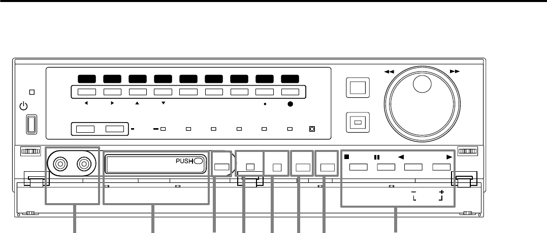
14. EMERGENCY indicator
Flashes during emergency recording and lights when
recording is completed.
15. LOCK indicator
Illuminates when simple lock or password lock is on.
16. LOCK button
Pressing it with a pointed object (such as a ballpoint
pen) while the MAIN switch (main power) on the rear
of the unit is on, will activate the simple lock or pass-
word lock. Moreover, the PASSWORD can be set on
the <PASSWORD SETTING> screen. The indicator
will light while the lock is active.
17. ANALOGUE OUT connectors
VIDEO OUT connector
Output connector for video signal (RCA pin).
AUDIO OUT connector
Output connector for audio signal (RCA pin).
18. COMPACT FLASH slot
Compact Flash Card can be used for saving/loading
data and menus. When not using the slot, attach the
COMPACT FLASH slot cover to prevent dust from
entering within the unit.
■ Inserting/Ejecting Compact Flash Card
Before using the Card, read the cautionary notes
described in the manual included with Compact Flash
Card.
<Inserting Card>
1. Remove the COMPACT FLASH slot cover attached to the
unit.
2. Please turn down the side which contains notch in right and
left, securely insert the Card until the CFC EJECT button pops
out.
Do not eject the Card when copying/restoring, copy-
ing/loading menus, or immediately after inserting the
Card. The Card or the contained data may become
damaged.
Securely insert the Compact Flash Card. Other-
wise, the unit may not work properly.
Please use the Compact Flash Card which we rec-
ommend. When a non recommended Card is used,
there is a possibility that reading and writing of data
may not operate correctly.
For usable Compact Flash Card check with your
dealer of purchase.
When using a new Card, be sure to execute CFC
DATA CLEAR in the <INFORMATION/SERVICE>
screen.
<Ejecting Card>
1. Press the CFC EJECT button and eject the Card.
2. Attach the COMPACT FLASH slot cover.
SEARCH
COPY SET UP
VIDEO OUT AUDIO OUT
COMPACTFLASH
STOP PAUSE REV. PLAY PLAY
PLAY
MODE
SHUTTLE
HOLD
TIMER
ENTER/
FF
CLEAR/
REW
REC/STOP
M-DET
PRE ALARM EMERGENCY LOCK
SPLIT/
SEQUENCE ZOOM
ACCESS
POWER
56789
1234
CFC EJECT Button
COPY
ZOOM / 0
SPLIT/
SEQUENCE
Compact Flash Card
AUDIO OUT
VIDEO OUT
SEARCH
COPY SET UP
VIDEO OUT AUDIO OUT
COMPACTFLASH
STOP PAUSE REV. PLAY PLAY
PLAY
MODE
SHUTTLE
HOLD
TIMER
ENTER/
FF
CLEAR/
REW
REC/STOP
M-DET
PRE ALARM LOCK
EMERGENCY
SPLIT/
SEQUENCE ZOOM / 0
56789
1234
OUTPUT
A/B
COMOUTPUT B
■ Front View (Inside of the door)
12
••••••••••••••••••••••••••••••••••••••••••••••••••••••••••••••••••••••••••••••••••••••••••••••••••••••••••••••••••••••••••••••••••••••••••••
19. COPY button
Press this button to display <COPY> menu. This
button lights when performing copy operation. Cop-
ies cannot be made when a card is not in the
COMPACT FLASH slot.
20. ALARM INTERRUPT button
When pressing this button, the unit will not accept
alarm signals or motion detection for 5 minutes. Dur-
ing this time, the button will flash.
21. WARNING RESET button
This button is used to clear on-screen warning dis-
play and clear data.
22. SET UP button
Press this button to display the <SETTINGS> menu.
23. SEARCH button
Press this button to display the <SEARCH > menu.
24. OPERATION buttons
STOP button
Press to stop playback.
PAUSE / SHUTTLE HOLD button
When pressing this button during playback, the unit
switches to still frame playback and the button lights.
When pressing this button again, the unit resumes
playback and the button turns off. When pressing
this button during shuttle playback, the set playback
speed is maintained even when letting go of the
SHUTTLE ring. (SHUTTLE HOLD)
REV. PLAY (REVERSE PLAY) button
When pressing this button, the unit switches to re-
verse playback and the button lights.
PLAY button
When pressing this button, the unit starts playback
and the button lights.
SEARCH
COPY SET UP
VIDEO OUT AUDIO OUT
COMPACTFLASH
STOP PAUSE REV. PLAY PLAY
PLAY
MODE
SHUTTLE
HOLD
18
17 19 20 21 22 23 24
ALARM
INTERRUPT
WARNING
RESET
TIMER
ENTER/
FF
CLEAR/
REW
REC/STOP
M-DET
PRE ALARM LOCK
EMERGENCY
SPLIT/
SEQUENCE ZOOM / 0
56789
1234
OUTPUT
A/B
COMOUTPUT B
ACCESS
POWER
PLAY MODE buttons
The playback interval can be changed during nor-
mal and reverse playback by pressing PLAY(+) or
REV. PLAY( - ).
Major operations and their functions (continued)
■ Front View (Inside of the door) (continued)
ENGLISH
13
••••••••••••••••••••••••••••••••••••••••••••••••••••••••••••••••••••••••••••••••••••••••••••••••••••••••••••••••••••••••••••••• Beginning
VIDEO
1
MAIN
OFF
ON
AC IN
~
234 56789
14
RESET
RS-232C
23 56789
1
ALARM IN
2
3
4
5
6
7
8
9
CLOCK ADJ
REC
EMERGENCY
MODE OUT 1
MODE OUT 2
MODE OUT 3
MODE OUT 4
MODE OUT 5
CALL OUT
CALL OUT GND
MAX 350mA
DC 12V OUT
GND
CAMERA OUT
RS-232C
RESET
CAMERA IN
INOUT
OUTPUT A
OUTPUT B
MIC
GND
AUDIO
100-240V
Y/C
ETHERNET
RECEIVE SEND
12 13
11
109
876
5
123 4
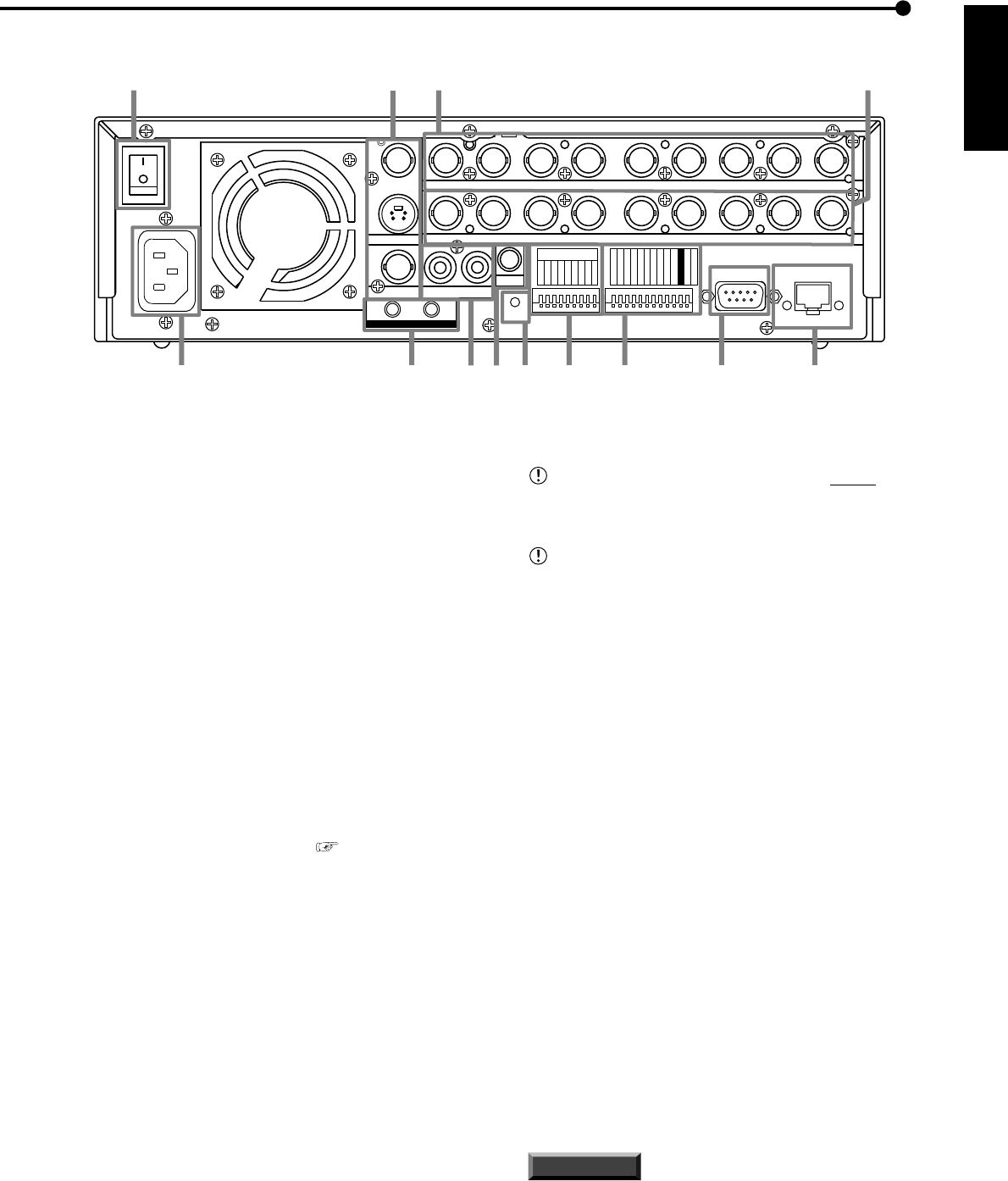
This unit must be earthed at all times. Never con-
nect this unit to a power outlet which does not have
an earth terminal.
Please use the AC power cord accessory.
6. GND terminals
It is the common GND terminal.
7. AUDIO connectors
AUDIO IN connector
Input connector for audio signal (RCA pin).
AUDIO OUT connector
Output connector for audio signal (RCA pin).
8. MIC jack
Input connector for microphone (600 ohm imped-
ance). Use of MIC for audio recording has priority to
use of the AUDIO IN connector.
9. RESET button
Pressing this button resets the unit and the power
turns off. In this case, video data, menu settings and
the current time are kept.
10. ALARM IN terminals
Input terminal for alarm signal.
11. I/O terminals
CLOCK ADJ terminal
Input terminal to set the present time. Time display is
adjusted to the nearest hour (00 minutes 00 seconds)
when this terminal receives the CLOCK ADJ signal.
INFORMATION
The on-screen clock can be reset to the nearest hour,
by applying a signal to the CLOCK ADJ terminal. For
example, if the current time is 11:29:59, it will be reset
to 11:00:00, and if the current time is 11:30:00, it will be
reset to 12:00:00.
1. MAIN switch
This is the main power switch. When using this unit,
set this switch to ON. Otherwise, the power cannot
be turned on/off using the POWER button on the front
of the unit.
2. VIDEO OUT connectors
OUTPUT A VIDEO connector
Output connector for video signal to monitor (BNC
connector).
OUTPUT A S(Y/C) connector
This is output connector for video signals that sepa-
rate brightness signals and color signals for higher
picture quality. Simultaneous output along with OUT-
PUT A VIDEO is also possible.
OUTPUT B connector
Output connector for video signal to monitor only for
live image (BNC connector)( see page 37). To
display the image, set “OUTPUT B ON/OFF” on the
<MPX DISPLAY SETTINGS> screen to “ON”. The
playback image cannot be put out to the OUTPUT B
connector.
3. CAMERA IN connectors
Input connector for signal of camera (BNC connector).
4. CAMERA OUT connectors
Camera video output connectors for use of BNC con-
nectors. If the MAIN switch is ON, the loop through
output is possible for the camera image inputted into
each CAMERA IN connector.
5. AC power socket
This socket connects to the power cord. Earth ter-
minal is for safety. Use the 100 ~ 240V plug with
earth for the power of this unit.
■ Rear View
14
•••••••••••••••••••••••••••••••••••••••••••••••••••••••••••••••••••••••••••••••••••••••••••••••••••••••••••••••••••• Beginning
VIDEO
1
MAIN
OFF
ON
AC IN
~
234 56789
14
RESET
RS-232C
23 56789
1
ALARM IN
2
3
4
5
6
7
8
9
CLOCK ADJ
REC
EMERGENCY
MODE OUT 1
MODE OUT 2
MODE OUT 3
MODE OUT 4
MODE OUT 5
CALL OUT
CALL OUT GND
MAX 350mA
DC 12V OUT
GND
CAMERA OUT
RS-232C
RESET
CAMERA IN
INOUT
OUTPUT A
OUTPUT B
MIC
GND
AUDIO
100-240V
Y/C
ETHERNET
RECEIVE SEND
12 13
11
109
876
5
123 4
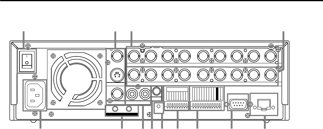
REC terminal
Input terminal to start recording. Not available dur-
ing timer recording.
EMERGENCY terminal
Input terminal initiating immediate shift to EMER-
GENCY recording mode compulsorily.
MODE OUT 1 ~ MODE OUT 5 terminals
Output terminal to indicate the unit’s current mode.
Select the unit’s condition by MODE OUT 1 ~ MODE
OUT 5 setting in the <REAR TERMINAL SETTINGS>
menu.
CALL OUT terminal / CALL OUT GND terminals
This is the ISOLATION output terminal. Information
that can be transmitted externally consists of CALL
OUT settings made on the <REAR TERMINAL SET-
TINGS> menu screen as well as fixed output set-
tings.
DC 12V OUT terminal
Will only output when the MAIN switch is ON. The
maximum electric current is 350mA.
12. RS-232C connector
This connector is used to connect to host device with
RS-232C connector. This unit can be controlled by
another device through this connector.
13. ETHERNET connector
Use a 10BASE-T cable to connect to the Ethernet
terminal. Please use the cable adapted to 10BASE-
T. DUPLEX MODE is HALF DUPLEX.
RECEIVE indicator
Illuminates when the unit is receiving a signal.
SEND indicator
Illuminates when the unit is transmitting a signal.
Major operations and their functions (continued)
■ Rear View (continued)
15
•••••••••••••••••••••••••••••••••••••••••••••••••••••••••••••••••••••••••••••••••••••••••••••••••••••••••••••••••••••••••• Connections
ENGLISH
VIDEO
1
MAIN
OFF
ON
AC IN
~
234 56789
14
RESET
RS-232C
23 56789
1
ALARM IN
2
3
4
5
6
7
8
9
CLOCK ADJ
REC
EMERGENCY
MODE OUT 1
MODE OUT 2
MODE OUT 3
MODE OUT 4
MODE OUT 5
CALL OUT
CALL OUT GND
MAX 350mA
DC 12V OUT
GND
CAMERA OUT
RS-232C
RESET
CAMERA IN
INOUT
OUTPUT A
OUTPUT B
MIC
GND
AUDIO
100-240V
Y/C
ETHERNET
RECEIVE SEND
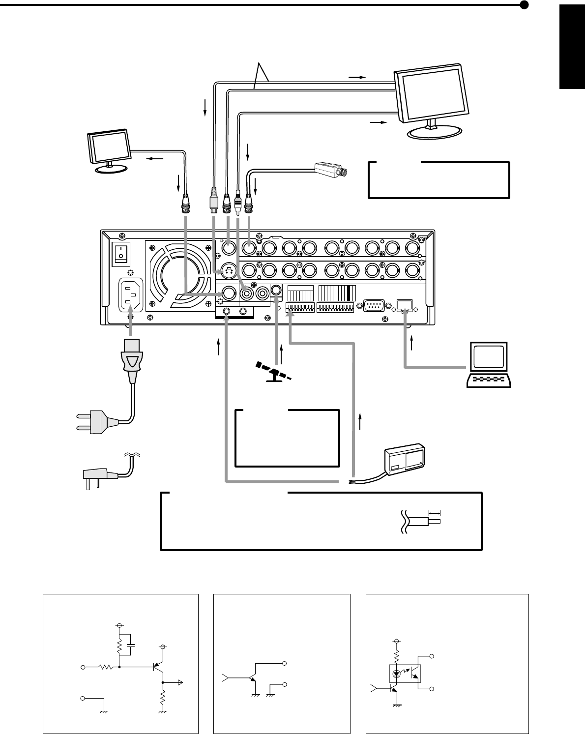
MONITOR
POWER CORD
for U.K
for the Continent
VIDEO MONITOR
(Only for the live image) To AUDIO IN connector
To OUTPUT A VIDEO or
OUTPUT A S(Y/C) connector
One of either codes
should be connected. To VIDEO IN or
S(Y/C) IN connector
To AUDIO OUT
connector
To CAMERA IN 1 connector
CAMERA #1
Up to 9 cameras
Processing the connecting line
Connection on the ALARM IN terminals and the I/O terminals
Compatible power lines ø0.32 ~ ø0.65 mm (AWG 28 ~ 22)
Cut the designated area from the electric wire’s outer covering
(vinyl portion).
5~7mm
To GND
terminal
To ALARM IN terminal
corresponds to the
CAMERA #.
SENSOR #1
To MIC jack
MICROPHONE
CAUTION
Connecting a coaxial transmission
camera wrong may damage the input
terminal. Be careful.
CAUTION
When a microphone is
connected to the MIC jack,
the MIC jack will be given
priority over the AUDIO IN
connector.
To OUTPUT B
connector
To VIDEO IN
connector
To ETHERNET
connector
HALF DUPLEX MODE
Connections
■ Connecting to CCTV camera, monitor, sensor
<Interface circuit inside the unit>
5V
5V
10kΩ
22kΩ
Input
terminal
0.047µF
GND
EMERGENCY/ALARM IN/REC/
CLOCK ADJ Input terminal
• Input Circuit
4.7kΩ
<Interface circuit inside the unit>
Output terminal
GND terminal
MODE OUT 1 - 5 Output terminal
• Output Circuit
<Interface circuit inside the unit>
CALL OUT terminal
CALL OUT GND terminal
CALL OUT Output terminal
• Output Circuit
16
••••••••••••••••••••••••••••••••••••••••••••••••••••••••••••••••••••••••••••••••••••••••••••••••••••••••••••••••• Connections
Connections (continued)
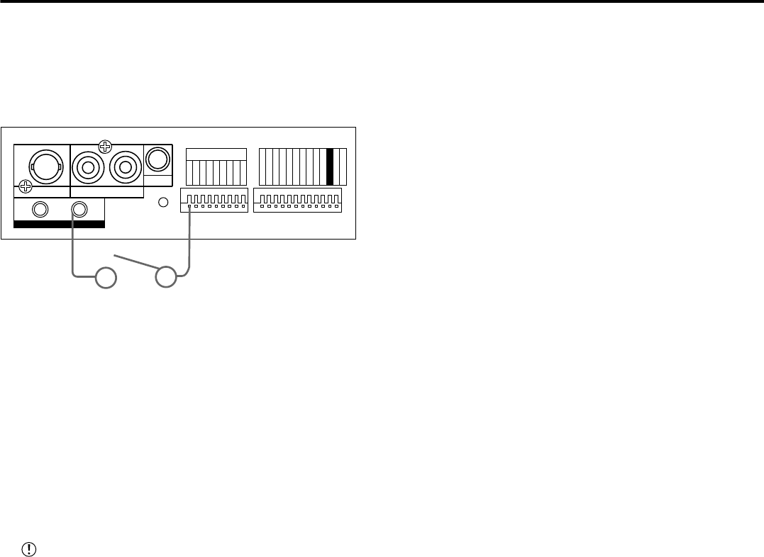
■ Alarm Recording Connection
Example : The diagram below shows an example of con-
nection for alarm signals corresponding to camera
number 1. (In the case of ALARM SETTING of default
setting.)
RESET
1
ALARM IN
2
3
4
5
6
7
8
9
CLOCK ADJ
REC
EMERGENCY
MODE OUT 1
MODE OUT 2
MODE OUT 3
MODE OUT 4
MODE OUT 5
CALL OUT
CALL OUT GND
MAX 350mA
DC 12V OUT
GND
RESET
INOUT
OUTPUT B
MIC
GND
AUDIO
ALARM SWITCH
■ Connecting with analog video recorder
This unit is equipped with video output (RCA) and audio
output (RCA) connectors on the front and OUTPUT A S(Y/
C), OUTPUT A VIDEO (BNC) and AUDIO OUT (RCA) con-
nectors on the rear. Video signals can be simultaneously
outputted from the video output connector on the front and
the OUTPUT A VIDEO/S(Y/C) connector on the rear. In
the same manner, audio signals can be outputted in simul-
taneously from the audio output connector on the front and
AUDIO OUT connector on the rear. By connecting an ana-
log video recorder to these terminals, recorded contents
can be copied.
Make sure to turn off this unit when connecting with
peripheral recording devices.
17
•••••••••••••••••••••••••••••••••••••••••••••••••••••••••••••••••••••••••••••••••••••••••••••••••••••••••••••• AUTO SET UP
ENGLISH
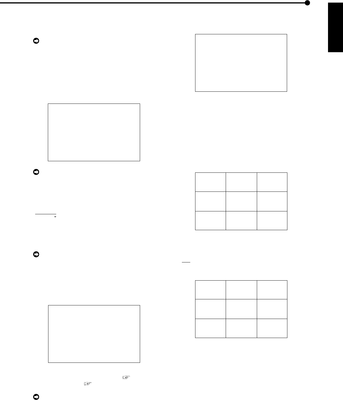
AUTO SET UP
■ AUTO SET UP
AUTO SET UP is displayed, in order to set up an indispen-
sable function, when this unit is turned on for the first time.
Only when the unit is turned on for the first time,
the AUTO SET UP screen is displayed automatically. It
is not automatically displayed after next time.
1. After connect the cameras and the monitors, turn on the
MAIN switch on the rear of the unit and wait until the ACCESS
indicator is turned off, then press the POWER button on the
front.
• The <LANGUAGE SELECTION> screen is displayed. The
language of the menu can be selected in this screen.
<LANGUAGE SELECTION>
>>
LANGUAGE ENGLISH
EXECUTE
JOG :SELECT
SHUTTLE>>:EXECUTE
POWER button operation will not be accepted while
the ACCESS indicator is flashing. Press the POWER
button after the indicator turns off.
2. Turn the SHUTTLE ring clockwise.
• The background of the setting changes to red and flashes.
• Setting ( default : “ENGLISH” )
“ENGLISH”, “FRANCAIS”, “DEUTSCH”, “ESPAÑOL”,
“
P
y
CCK
NN
”, “ITALIANO”
3. Turn the JOG dial to display the desired setting and turn the
SHUTTLE ring clockwise.
• The setting is confirmed and flashing stops.
Beware while setting the AUTO SET UP, the menu
screen can not be exited. Furthermore the screen al-
ready set can not be displayed again.
4. Turn the JOG dial to move the cursor to “EXECUTE”, and
turn the SHUTTLE ring clockwise.
• The <TIME DATE ADJUST> screen appears.
• The date/time is set in this screen.
<TIME DATE ADJUST>
>>
DAYLIGHT SAVING OFF
DAY 01
MONTH 01
YEAR 2004
TIME 00:00:00
APPLY
EXECUTE
JOG :SELECT
SHUTTLE>>:EXECUTE
5. Set the desired setting in this screen referring to “
♦
DAYLIGHT SAVING/DAYLIGHT SETTING ( see page 20)”,
“
♦
TIME DATE ADJUST ( see pages 20,21)”.
By turning the JOG dial to the cursor to “APPLY”
and turn the SHUTTLE ring clockwise, “00:00:00” of
“TIME” will start after the moment of turning the SHUT-
TLE ring.
6. Turn the JOG dial to move the cursor to “EXECUTE”, and
turn the SHUTTLE ring clockwise.
• “PERFORM AUTO SET UP?” is displayed on the screen.
PERFORM AUTO SET UP?
>>
YES
NO
SHUTTLE>>:EXECUTE
7-1. (When not execute AUTO SET UP • • • )
Select “NO” by turning the JOG dial and turn the SHUTTLE
ring clockwise.
• “SETTING UP...” is displayed on the screen, and the unit
starts-up.
7-2. (When execute AUTO SET UP • • • )
Select “YES” by turning the JOG dial and turn the SHUTTLE
ring clockwise.
• The <CAMERA CHECK> screen appears.
• The cameras connected and the video condition can be
confirmed in this screen.
<CAMERA CHECK>
>>
EXECUTE
CHECK CAMERA CONNECTION AND
IMAGE BEFORE EXECUTE
SHUTTLE>>:EXECUTE
8. Turn the SHUTTLE ring clockwise.
• The <AUTO RECORD SETTING> screen appears.
• The period of the record can be set.
• Setting of AUTO RECORD SETTING ( default : “24H” )
“24H”, “48H”, “72H”, “96H”, “120H”, “144H”, “1WEEK”,
“2WEEK”, “3WEEK”, “1MONTH”, “2MONTH”, “3MONTH”,
“4MONTH”, “5MONTH”, “6MONTH”, “1YEAR”
<AUTO RECORD SETTING>
>>
RECORDING CYCLE 24H
EXECUTE
JOG :SELECT
SHUTTLE>>:EXECUTE
9. Turn the SHUTTLE ring clockwise.
• The background of the setting changes to red and flashes.
10. Turn the JOG dial to display the desire setting and turn the
SHUUTLE ring cloclwise.
• The setting is confirmed and flashing stop.
11. Turn the JOG dial to move the cursor to “EXECUTE”, and
turn the SHUTTLE ring clockwise.
• The <RECORD SETTING> screen appears.
• The recording interval and recording picture quality of
normal recording and alarm recording corresponding to each
camera numbers can be set in this screen.
18
•••••••••••••••••••••••••••••••••••••••••••••••••••••••••••••••••••••••••••••••••••••••••• AUTO SET UP / Initial settings
/ Initial settings
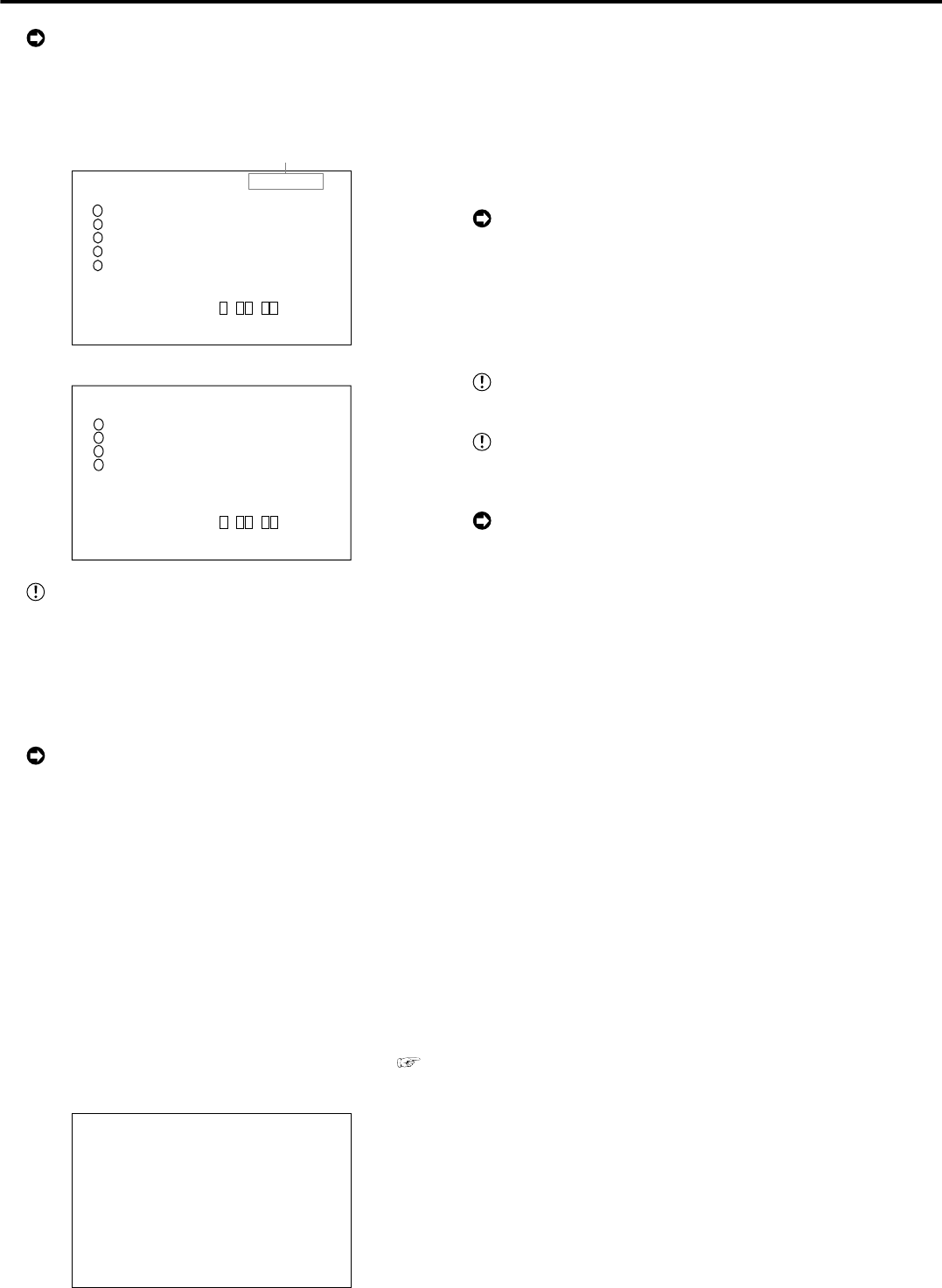
AUTO SET UP (continued)
The <RECORD SETTING> screen consists of 2
pages. The second page is displayed when turning the
JOG dial to move the cursor to “NEXT PAGE”, and turn
the SHUTTLE ring clockwise.
<RECORD SETTING> 1/2
Camera selection during alarm recording
<RECORD SETTING> ALARM CH
NO PPS GRADE A-PPS A-GRADE
>>
12.5P SUPER 12.5P SUPER
------ SUPER ------ SUPER
------ SUPER ------ SUPER
12.5P SUPER 12.5P SUPER
------ SUPER ------ SUPER
<ESTD REC> D H M
NEXT PAGE
4
5
1
2
3
<RECORD SETTING> 2/2
<RECORD SETTING>
NO PPS GRADE A-PPS A-GRADE
>>
------ SUPER ------ SUPER
12.5P SUPER 12.5P SUPER
------ SUPER ------ SUPER
------ SUPER ------ SUPER
<ESTD REC> D H M
PRESS POWER BUTTON TO EXIT
6
7
9
8
According to the number of the cameras connected
and the value of “RECORDING CYCLE”, the most suit-
able setting of the “PPS”, “A-PPS”, “GRADE” and “A-
GRADE” are set automatically.
12. When the setting is complete, press the POWER button.
• “SETTING UP...” is displayed on the screen, and the unit
starts-up.
To execute AUTO SET UP again, press and hold
the camera number button 1 and press the POWER
button, when the MAIN switch is set to ON and the
POWER button is set to OFF. The <CAMERA CHECK>
screen appears. However all menu of record setting
will be reset.
■ INITIALIZATION
The <INITIALIZATION> setting is used to select the mode of
peripheral recording devices connected to SCSI connector
ID4•ID5, to make HDD SETTING, and to initialize the HDD.
♦ HDD SETTING
The HDD SETTING can be set to MIRRORING (simulta-
neous recording to the internal HDD as a pair), PARTITION
(an independent partition that can be set within the total
HDD memory specifically for ALARM RECORDING). (
see pages 74,75 “MIRRORING”, “PARTITION”)
<INITIALIZATION>
>>
HDD SETTING NORMAL
POWER OFF
INITIALIZATION
ALL DATA WILL BE ERASED
WHEN PROCEED INITIALIZATION
♦ INITIALIZATION
Please perform initialization, when a <INITIALIZATION>
setup is changed.
1. Turn ON the MAIN switch on the rear of the unit, and wait
until the ACCESS indicator goes off. Hold down the REC/STOP
button, and press the POWER button on the front of the unit.
• The unit starts-up, and the <INITIALIZATION> screen is
appears.
POWER button operation will not be accepted while
the ACCESS indicator is flashing. Press the POWER
button after the indicator turns off.
2. Select “INITIALIZATION” by turning the JOG dial, and turn
the SHUTTLE ring clockwise.
• The setting is made, and the display returns to normal after
initialization.
Settings are not confirmed unless you perform
“INITIALIZATION”.
Performing “INITIALIZATION” initializes all data on
the HDD. It deletes the complete ALARM LIST, and
the next entry is registered from 00001.
Select “POWER OFF” to abort initialization.
19
ENGLISH
•••••••••••••••••••••••••••••••••••••••••••••••••••••••••••••••••••••••••••••••••••••••••••••••••••••••••••••••••••••• Basic Operations
Basic Operations
■ Multiplexer functions
Buttons on the front of the unit can be used to perform
some of the multiplexer functions.
♦ Multiplexer buttons
MOVE button
2 SPLIT/SEQUENCE button
3 ZOOM button
1 Camera number buttons (1 to 9)
SPLIT/
SEQUENCE
ZOOM / 0
56789
1234
1. Camera number buttons (1 to 9)
Video images of cameras connected to CAMERA IN termi-
nals 1 to 9 on the rear of the unit are displayed.
By pressing a camera number button, video im-
ages can be displayed even if the camera is not set
for recording.
2. SPLIT/SEQUENCE button
The screen switches in order of SPLIT9 SCREEN
SETTING, 3 types of SPLIT4 SCREEN SETTING (a, b and
c), SPLIT4 SEQUENTIAL and SINGLE SEQUENTIAL set
in the <MPX DISPLAY SETTINGS> screen (SEQUENTIAL
display is skipped during playback).
Pressing the ZOOM button for more than 1
second on the front of this unit can switch the
operation of camera number buttons and the SPLIT/
SEQUENCE button to the screen of the monitor
connected to the OUTPUT B connector. Pressing
the ZOOM button for more than 1 second again can
switch to the screen of the monitor connected to the
OUTPUT A connector.
3. ZOOM button
When this button is pressed during single screen display,
magnification 100% screen appears and the magnification
centre point (X) is displayed at the centre. Pressing the
button again will switch the magnification to 200% and then
400%. By pressing the MOVE buttons, the magnified screen
can be moved vertically/horizontally with the centre point
as the axis ( see “ZOOM button operations”, page 35).
When the ZOOM button is pressed, camera number
buttons 1 to 4 become the MOVE buttons.
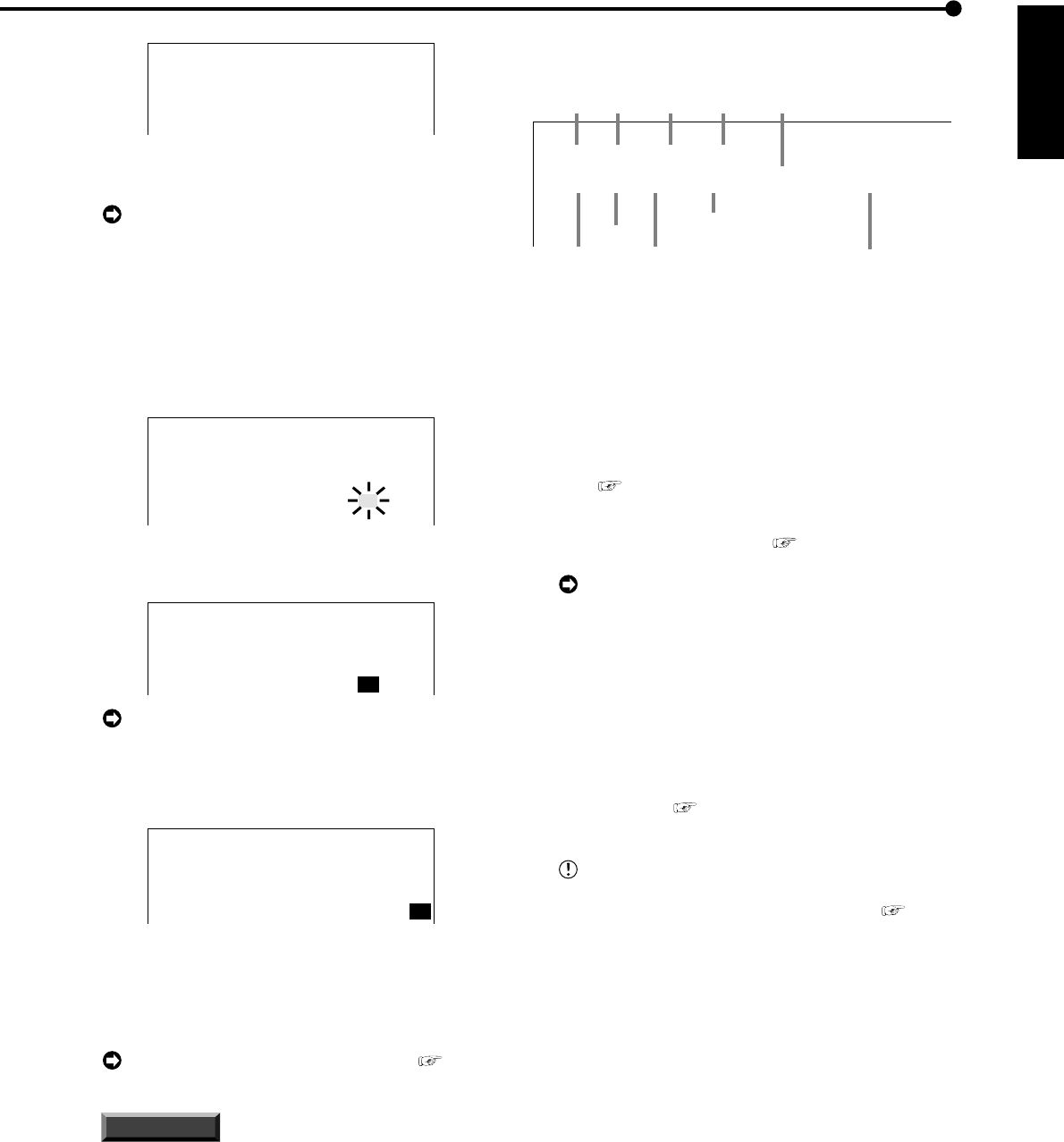
■ Menu settings
The operational conditions of this unit can be set in the
menu screens according to use. Although the setting
method will differ slightly depending on the menu screen,
the basic setting method of using the JOG dial and SHUT-
TLE ring will remain the same. e.g. setting the display
mode.
SHUTTLE ring
JOG dial
Example : Set DISPLAY MODE to “3” ( default : “1” ).
1. Set the MAIN switch on the rear of the unit to ON. Press
the POWER button on the front after the ACCESS indicator
turns off.
• “SETTING UP...” appears on the screen and the unit is
booted.
POWER button operation will not be accepted
while the ACCESS indicator is flashing. Press the
POWER button after the indicator turns off.
2. After boot-up, press the SET UP button inside the door on
the front of the unit.
• The <SETTINGS> screen appears.
<SETTINGS>
>>
TIME DATE/DISPLAY SETTINGS
MPX DISPLAY SETTINGS
MOTION DETECTION SETTINGS
RECORD SETTINGS
TIMER PROGRAM SETTINGS
INITIAL SET UP/INFORMATION
QUICK SETTINGS
MEMO:
When the SET UP button is pressed and the
menu screen appears, the background darkens and
the displayed characters become easier to see.
3. Check to see that the cursor (>>) is positioned at “TIME
DATE/DISPLAY SETTINGS”, and then turn the SHUTTLE ring
clockwise.
• The <TIME DATE/DISPLAY SETTINGS> screen appears (
see page 32).
<TIME DATE/DISPLAY SETTINGS>
>>
TIME DATE ADJUST
DISPLAY MODE 1
CLOCK LOCATION SETTING
CAMERA DISPLAY NUMBER
CAMERA TITLE/MEMO SETTING
DUPLEX MODE DISPLAY BOTTOM
<MODE 1>
01-01-2004 00:00:00
4. Turn the JOG dial to move the cursor to “DISPLAY MODE”
and turn the SHUTTLE ring clockwise.
• The background of the “DISPLAY MODE” setting turns red
and flashes.
When turning the JOG dial clockwise, the cursor
(>>) moves down. When turning counterclockwise,
the cursor (>>) moves up.
5. Turn the JOG dial to display “3”.
• The display mode sample on the bottom of the screen
changes to <MODE 3>.
6. Turn the SHUTTLE ring clockwise.
• The setting is confirmed and flashing stops.
• To continue with other settings, repeat steps 4 and 5.
When turning the SHUTTLE ring counterclockwise
while the setting is flashing, the setting will return to
the previous setting.
To exit the screen, turn the SHUTTLE ring
counterclockwise.
20
••••••••••••••••••••••••••••••••••••••••••••••••••••••••••••••••••••••••••••••••••••••••••••••••••••••••••••••••••••••••••••••••••••••••••••
Basic Operations (continued)
<TIME DATE/DISPLAY SETTINGS>
TIME DATE ADJUST
>>
DISPLAY MODE 3
CLOCK LOCATION SETTING
CAMERA DISPLAY NUMBER
CAMERA TITLE/MEMO SETTING
DUPLEX MODE DISPLAY BOTTOM
<MODE 3>
01-01-2004 THU
00:00:00 12.5P 99
%
A00001
♦ To return to the normal screen from a menu screen
The procedure to return to the normal screen after com-
pleting menu screen settings using the JOG dial/SHUT-
TLE ring is detailed below.
1. Check to see that the setting item is no longer flashing and
the item has been changed to the desired setting.
• The setting has not been confirmed if the item is flashing.
Refer to the previous setting procedure to confirm the setting.
• To continue with other settings or to check the setting item,
turn the SHUTTLE ring counterclockwise once to return to
the previous screen.
This operation is not accepted when the setting
item is flashing.
2-1. (To return to the normal screen by moving up menu
screens one at a time • • • )
• Turn the SHUTTLE ring counterclockwise for the amount of
menu screens opened. The previous menu screen is
displayed every time the SHUTTLE ring is turned
counterclockwise.
2-2. (To directly return to the normal screen • • • )
• Press the SET UP button to clear the menu screen and return
to the normal screen.
The menu screen will not be cleared even when
pressing the SET UP button when the setting item
is flashing.
♦ DAYLIGHT SAVING/DAYLIGHT SETTING
The clock is put forward one hour by activating this setting.
The default setting for this function is “OFF”. On the DAY
LIGHT SAVING in <TIME DATE ADJUST> menu, turn the
JOG dial to flash “AUTO” (the daylight saving function is
automatically activated). Turn the SHUTTLE ring clockwise
to enter the selection.
In the “DAYLIGHT SETTING” setting, start/end time of the
“DAYLIGHT SAVING” function can be checked and
changed.
Example : Set the start time of the “DAYLIGHT SAVING”
function “IN” to “MON”, “1ST”, “APR” and “02:00”.
( default : “SUN”, “LAST”, “MAR”, “01:00” ).
1. Press the SET UP button to display the <SETTINGS>
screen.
2. Check to see that the cursor (>>) is positioned at “TIME
DATE/DISPLAY SETTINGS”, and then turn the SHUTTLE ring
clockwise.
• The <TIME DATE/DISPLAY SETTINGS> screen appears.
3. Check to see that the cursor is positioned at “TIME DATE
ADJUST”, and then turn the SHUTTLE ring clockwise.
• The <TIME DATE ADJUST> screen appears.
<TIME DATE ADJUST>
>>
DAYLIGHT SAVING OFF
DAY 01
MONTH 01
YEAR 2004
TIME 00:00:00
DAYLIGHT SETTING
DAY OF WEEK MONTH TIME
IN SUN LAST MAR 01:00
OUT SUN LAST OCT 02:00
JOG :SELECT
SHUTTLE>>:EXECUTE
4. Turn the JOG dial to move the cursor (>>) to “IN” and turn
the SHUTTLE ring clockwise twice.
• The “DAY” display reverses in color when the SHUTTLE
ring is turned the first time. When the ring is turned for the
second time, the display turns red and flashes.
5. Turn the JOG dial to display “MON” and turn the SHUTTLE
ring clockwise.
• The setting is confirmed and flashing stops.
6. Turn the JOG dial clockwise to move the cursor (>>) to
“WEEK”.
7. Repeat steps 4, 5 and 6 to set “WEEK”, “MONTH” and
“TIME”.
8. Turn the SHUTTLE ring clockwise.
• The setting is confirmed and flashing stops.
9. Turn the SHUTTLE ring counterclockwise or press the SET
UP button.
♦ TIME DATE ADJUST
Before starting recording, it is necessary to set
accurately the current date and time.
Example : Set the date/time to 28/10/2004 6:30pm
(18:30)( default : “01/01/2004 00:00:00” ).
1. Press the SET UP button to display the <SETTINGS>
screen.
2. Check to see that the cursor (>>) is positioned at “TIME
DATE/DISPLAY SETTINGS”, and then turn the SHUTTLE ring
clockwise.
• The <TIME DATE/DISPLAY SETTINGS> screen appears.
3. Check to see that the cursor is positioned at “TIME DATE
ADJUST”, and then turn the SHUTTLE ring clockwise.
• The <TIME DATE ADJUST> screen appears.
<TIME DATE ADJUST>
>>
DAYLIGHT SAVING OFF
DAY 01
MONTH 01
YEAR 2004
TIME 00:00:00
4. Turn the JOG dial to move the cursor to “DAY” and turn the
SHUTTLE ring clockwise.
• The background of “DAY” changes to red and flashes.
<TIME DATE ADJUST>
DAYLIGHT SAVING OFF
>>
DAY 01
MONTH 01
YEAR 2004
TIME 00:00:00
5. Turn the JOG dial to display “28” and turn the SHUTTLE
ring clockwise.
• The setting is confirmed and flashing stops.
21
ENGLISH
•••••••••••••••••••••••••••••••••••••••••••••••••••••••••••••••••••••••••••••••••••••••••••••••••••••••••••••••••••••• Basic Operations
<TIME DATE ADJUST>
DAYLIGHT SAVING OFF
>>
DAY 28
MONTH 01
YEAR 2004
TIME 00:00:00
6. Turn the JOG dial clockwise to move the cursor (>>) to
“MONTH”.
When turning the JOG dial clockwise, the cursor
(>>) moves down. When turning counterclockwise,
the cursor (>>) moves up.
7. Repeat steps 4 ~ 6 to set “MONTH” and “YEAR”.
8. Turn the JOG dial to move the cursor (>>) to “TIME” and
turn the SHUTTLE ring clockwise twice.
• The “TIME” display reverses in color when the SHUTTLE
ring is turned the first time. When the ring is turned for the
second time, the display turns red and flashes.
<TIME DATE ADJUST>
DAYLIGHT SAVING OFF
DAY 28
MONTH 10
YEAR 2004
TIME 00:00:00
9. Turn the JOG dial to display “18” and turn the SHUTTLE
ring clockwise.
• The setting is confirmed and flashing stops.
<TIME DATE ADJUST>
DAYLIGHT SAVING OFF
DAY 28
MONTH 10
YEAR 2004
TIME 18:00:00
The time is indicated using the 24-hour system.
10. Repeat steps 8 and 9 to set “MINUTE” and “SECOND”.
11. Turn the SHUTTLE ring clockwise.
• The setting is confirmed and flashing stops.
<TIME DATE ADJUST>
DAYLIGHT SAVING OFF
DAY 28
MONTH 10
YEAR 2004
TIME 18:30:00
12. Turn the SHUTTLE ring counterclockwise.
♦ Present time display
When turning on the unit power, the time/date display shown
to the right appears (in the case of DISPLAY MODE 3).
For setting other display modes, see
“DISPLAY MODE” page 32.
INFORMATION
This unit uses 4 digits to display the year. The
allowed display range is 99 years between 1/1/
2001 ~ 31/12/2099. The unit is also equipped with
a function to automatically calculate leap years.
The date returns to the year 2001 after 31/12/
2099.
♦ Recorded capacity display function
01 - 01 - 2004
THU
00 : 00 : 00 12.5P 99% A00001
Year
Month
Day Day of
the week
Alarm recording number
Minute
Second
Hour
Playback interval
(Single screen playback only)
Recorded capacity of
the Hard Disk
This unit displays the used space of the specified record-
ing device (HDD) on the screen when “REMAIN HDD” of
the <REAR TERMINAL SETTINGS> screen is set to
“MAIN”, “SUB”. The “%” indicates the ratio detected as HDD
against the total HDD capacity. The following settings are
required to enable this function.
1) Select the device and set the remaining capacity using
“REMAIN HDD” of the <REAR TERMINAL SETTINGS>
screen ( see page 50).
2) Select “3” for “DISPLAY MODE” in the <TIME DATE/
DISPLAY SETTINGS> screen ( see page 32).
During recording, the used HDD space is dis-
played. When recording is stopped, the display is
cleared (with the exception of when pausing record-
ing). The HDD usage display appears again after a
few moments when recording is started once more.
■ Basic manual recording
Normal recording using manual operation is explained here.
Before starting recording, recording settings must be
checked. After checking the settings of “HDD REPEAT REC
MAIN”, “HDD REPEAT REC SUB” in the <HDD SET-
TINGS> screen ( see page 47), the REC mode set-
tings are made.
Settings here are for normal recording only. For
timer recording, settings must be made on the
<TIMER PROGRAM SETTINGS> screen ( see
page 46).
22
••••••••••••••••••••••••••••••••••••••••••••••••••••••••••••••••••••••••••••••••••••••••••••••••••••••••••••••••••••••••••••••••••••••••••••
Basic Operations (continued)
25P
12.5P
8.333P
6.25P
5P
4.167P
3.125P
2.5P
1P
0.5P
0.25P
0.125P
25P
12.5P
8.333P
6.25P
5P
4.167P
3.125P
2.5P
1P
0.5P
0.25P
0.125P
12.5P
6.25P
4.167P
3.125P
2.5P
2.083P
1.563P
1.25P
0.5P
0.25P
0.125P
0.063P
12.5P
6.25P
4.167P
3.125P
2.5P
2.083P
1.563P
1.25P
0.5P
0.25P
0.125P
0.063P
8.33P
4.165P
2.777P
2.083P
1.666P
1.388P
1.041P
0.833P
0.333P
0.167P
0.083P
0.042P
8.33P
4.165P
2.777P
2.083P
1.666P
1.388P
1.041P
0.833P
0.333P
0.167P
0.083P
0.042P
6.25P
3.125P
2.083P
1.563P
1.25P
1.042P
0.781P
0.625P
0.25P
0.125P
0.063P
0.031P
6.25P
3.125P
2.083P
1.563P
1.25P
1.042P
0.781P
0.625P
0.25P
0.125P
0.063P
0.031P
5P
2.5P
1.667P
1.25P
1P
0.833P
0.625P
0.5P
0.2P
0.1P
0.05P
0.025P
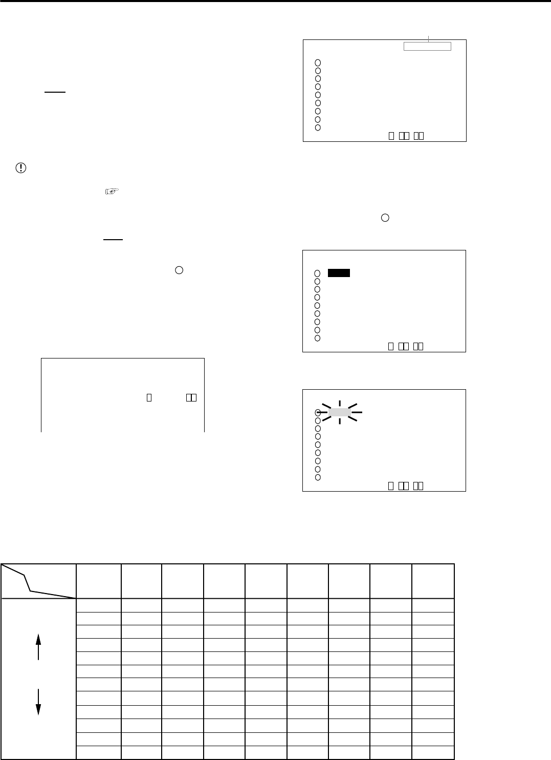
Number of
operational
cameras
PPS
SHORT
Recording
interval
LONG
# 1 # 2 # 3 # 4 # 5 # 6 # 7 # 8 # 9
Relationship between the number of operational cameras and available “PPS” (pictures per second)
♦ Setting the recording interval and recording
picture quality for normal recording
To perform normal recording, “PPS” and “GRADE” must
be set for each camera.
Setting of “PPS” ( default : “2.5P” )
“5P”, “2.5P”, “1.667P”, “1.25P”, “1P”, “0.833P”,
“0.625P”, “0.5P”, “0.2P”, “0.1P”, “0.05P”, “0.025P”,
“- - - - - -”
“- - - - - -” : Recording cannot be performed with
camera set to this item.
Available recording intervals will vary according
to the number of cameras operating or ALARM RE-
CORDING settings ( see page 41). Interval dis-
plays will be according to the chart.
Setting of “GRADE” ( default : “STD” )
“SUPER”, “HIGH”, “STD”(STANDARD), “BASIC”,
“LONG”
Example : Set “PPS” of camera number “
1
” to “0.5P” and
“GRADE” to “HIGH” for normal recording.
1. Press the SET UP button to display the <SETTINGS> screen.
2. Turn the JOG dial to move the cursor to “RECORD
SETTINGS” and turn the SHUTTLE ring clockwise.
• The <RECORD SETTINGS> screen appears.
<RECORD SETTINGS>
>>
ALARM SETTING
RECORD SETTING
ALARM REC DURATION 5S
PRE ALARM REC ( S ) S
MOTION DET REC ALARM
3. Turn the JOG dial to move the cursor to “RECORD
SETTING” and then turn the SHUTTLE ring clockwise.
• The <RECORD SETTING> screen appears.
<RECORD SETTING>
>>
ALARM CH
NO PPS GRADE A-PPS A-GRADE
2.5P STD 2.5P STD
2.5P STD 2.5P STD
2.5P STD 2.5P STD
2.5P STD 2.5P STD
2.5P STD 2.5P STD
2.5P STD 2.5P STD
2.5P STD 2.5P STD
2.5P STD 2.5P STD
2.5P STD 2.5P STD
<ESTD REC> D H M
<RECORD SETTING>
Camera selection during alarm recording
9
7
4
5
6
1
2
3
8
About <ESTD REC>
• The estimated recordable time is displayed as <ESTD REC>
depending on the “PPS” and “GRADE” settings. (The time
will not change when changing the alarm recording settings.)
4. Turn the JOG dial to select “
1
” , and then turn the SHUTTLE
ring clockwise.
• The “PPS” setting reverses in color.
<RECORD SETTING> ALARM CH
NO PPS GRADE A-PPS A-GRADE
2.5P STD 2.5P STD
2.5P STD 2.5P STD
2.5P STD 2.5P STD
2.5P STD 2.5P STD
2.5P STD 2.5P STD
2.5P STD 2.5P STD
2.5P STD 2.5P STD
2.5P STD 2.5P STD
2.5P STD 2.5P STD
<ESTD REC> D H M
9
7
4
5
6
1
2
3
8
5. Turn the SHUTTLE ring clockwise again.
• The background of the “PPS” setting turns red and flashes.
<RECORD SETTING> ALARM CH
NO PPS GRADE A-PPS A-GRADE
2.5P STD 2.5P STD
2.5P STD 2.5P STD
2.5P STD 2.5P STD
2.5P STD 2.5P STD
2.5P STD 2.5P STD
2.5P STD 2.5P STD
2.5P STD 2.5P STD
2.5P STD 2.5P STD
2.5P STD 2.5P STD
<ESTD REC> D H M
9
7
4
5
6
1
2
3
8

23
ENGLISH
•••••••••••••••••••••••••••••••••••••••••••••••••••••••••••••••••••••••••••••••••••••••••••••••••••••••••••••••••••••• Basic Operations
The menu screen will not be cleared even when
pressing the SET UP button when the setting item
is flashing.
6. Turn the JOG dial to select “0.5P” and turn the SHUTTLE
ring clockwise.
• Setting is confirmed and flashing stops.
<RECORD SETTING> ALARM CH
NO PPS GRADE A-PPS A-GRADE
0.5P STD 2.5P STD
2.5P STD 2.5P STD
2.5P STD 2.5P STD
2.5P STD 2.5P STD
2.5P STD 2.5P STD
2.5P STD 2.5P STD
2.5P STD 2.5P STD
2.5P STD 2.5P STD
2.5P STD 2.5P STD
<ESTD REC> D H M
9
7
4
5
6
1
2
3
8
7. Turn the JOG dial clockwise to reverse display “GRADE”
and turn the SHUTTLE ring clockwise.
• The background of the “GRADE” setting turns red and
flashes.
<RECORD SETTING> ALARM CH
NO PPS GRADE A-PPS A-GRADE
0.5P STD 2.5P STD
2.5P STD 2.5P STD
2.5P STD 2.5P STD
2.5P STD 2.5P STD
2.5P STD 2.5P STD
2.5P STD 2.5P STD
2.5P STD 2.5P STD
2.5P STD 2.5P STD
2.5P STD 2.5P STD
<ESTD REC> D H M
9
7
4
5
6
1
2
3
8
When the setting item is flashing, the menu
screen cannot be cleared even when pressing the
SET UP button.
8. Turn the JOG dial to select “HIGH” and turn the SHUTTLE
ring clockwise.
• The setting is confirmed and flashing stops.
9
7
4
5
6
1
2
3
8
<RECORD SETTING> ALARM CH
NO PPS GRADE A-PPS A-GRADE
0.5P HIGH 2.5P STD
2.5P STD 2.5P STD
2.5P STD 2.5P STD
2.5P STD 2.5P STD
2.5P STD 2.5P STD
2.5P STD 2.5P STD
2.5P STD 2.5P STD
2.5P STD 2.5P STD
2.5P STD 2.5P STD
<ESTD REC> D H M
9. When the setting is complete, turn the SHUTTLE ring
counterclockwise.
• The cursor appears to the camera number on the left.
• When continuing with other camera number settings, turn
the JOG dial to move the cursor to the desired camera number
and repeat steps 4 ~ 9 to perform settings.
<RECORD SETTING> ALARM CH
NO PPS GRADE A-PPS A-GRADE
>>
0.5P HIGH 2.5P STD
2.5P STD 2.5P STD
2.5P STD 2.5P STD
2.5P STD 2.5P STD
2.5P STD 2.5P STD
2.5P STD 2.5P STD
2.5P STD 2.5P STD
2.5P STD 2.5P STD
2.5P STD 2.5P STD
<ESTD REC> D H M
9
7
4
5
6
1
2
3
8
10. Turn the SHUTTLE ring counterclockwise three times or
press the SET UP button to return to the normal screen.
11. Press the REC/STOP button.
• The REC/STOP button turns on and recording starts.
12. To stop recording, press the REC/STOP button for more
than 1 second.
• Recording stops and the REC/STOP button turns off.
REC/STOP
■ Basic playback
This unit allows recorded video to be played back using
various methods. The basic playback described here is the
most common method for playback.
This unit will stop playback when a request for
acquisition of live images is communicated during
playback.
This unit will not playback while a request for the
acquisition of live images is being communicated.
1. Press the PLAY button ( inside the front door) on the front of
the unit.
• Recorded contents of the HDD are played back.
• After turning the power on, the oldest recorded video is
played back first. Otherwise, playback resumes at the position
of the previous playback.
STOP PAUSE REV. PLAY PLAY
When the “HDD REPEAT PLAY” setting in the
“HDD SETTINGS” is set to “OFF”, playback is
stopped when reaching the end of the physical HDD
or recorded section. When the “HDD REPEAT PLAY”
setting is set to “ON”, recorded video data is played
back repeatedly ( see “HDD REPEAT PLAY”,
page 47).
2-1. (To change HDD or Compact Flash Card playback device
• • • )
• Setting ( default : “MAIN” )
“MAIN” : Select when playing back MAIN HDD contents.
“SUB” : Select when playing back SUB HDD contents.
“CFC” : Select when playing back CFC contents.
• When changing the playback device to Compact Flash Card,
press the SEARCH button twice ( see page 67) to display
the <SEARCH SELECTION> screen and select “CFC”
(Compact Flash Card) in “PLAYBACK DEVICE”.
“SUB” is appeared on the screen when
“PARTITION” is selected on “HDD SETTING” of the
<INITIALIZATION> screen.
2-2. Press the PLAY button.
• Plays from the playback device that has been selected.
24
••••••••••••••••••••••••••••••••••••••••••••••••••••••••••••••••••••••••••••••••••••••••••••••••••••••••••••••••••••••••••••••••••••••••••••
Basic Operations (continued)
3. To pause playback, press the PAUSE button.
• To resume playback, press the PAUSE button again or press
the PLAY button.
4. To stop playback, press the STOP button.
• During HDD playback/pause, playback will start the next
time from the paused position.
• During CFC playback/pause, playback will start the next time
from the oldest recorded video on the media.
■ Basic search
This unit displays a menu of most used search functions
simply by pressing the SEARCH button.
This unit will not move to search mode when a
request for acquisition of live images is
communicated while search mode is set. Also, this
unit will not search when a request for the acquisition
of live images has been communicated.
This unit will not search while a request for the
acquisition of live images is being communicated.
♦ TIME DATE SEARCH
On this unit, various search functions are available for
searching the start point of video clips. In this section, the
most common search method referred to as time/date
search is explained. With this method, searching is possi-
ble by date, hour, minute, second and specified camera
number.
Example : Search a scene recorded on the MAIN HDD
with time/date stamp of 03/03/2004 9:25:40pm
(21:25:40) using camera number “
3
”.
1. Press the SEARCH button to display the <TIME DATE
SEARCH> screen.
• The default setting of the search menu displayed when
pressing the SEARCH button is “TIME DATE SEARCH”.
<TIME DATE SEARCH>
>>
01-01-2004 00:00:00
EXECUTE(FORWARD)
MAIN
START 02-02-2004 00:00:00
END 04-04-2004 12:30:15
PUSH SEARCH KEY FOR
SEARCH SELECTION
2. Check to see that the cursor is next to the search date and
turn the SHUTTLE ring clockwise twice.
• The display reverses in color when the SHUTTLE ring is
turned the first time. When the ring is turned for the second
time, the display turns red and flashes.
3. Turn the JOG dial to display “03” for “DAY” and turn the
SHUTTLE ring clockwise.
• Setting is confirmed and flashing stops.
4. Turn the JOG dial to reverse display “MONTH” and turn the
SHUTTLE ring clockwise.
• The background of the setting item changes to red and
flashes.
5. Turn the JOG dial to display “03” for “MONTH” and turn the
SHUTTLE ring clockwise.
• Setting is confirmed and flashing stops.
6. Repeat steps 4 and 5 to set “YEAR”, “HOUR”, “MINUTE”
and “SECOND”.
<TIME DATE SEARCH>
>>
03-03-2004 21:25:40
EXECUTE(FORWARD)
MAIN
START 02-02-2004 00:00:00
END 04-04-2004 12:30:15
PUSH SEARCH KEY FOR
SEARCH SELECTION
To exit the <TIME DATE SEARCH> screen without
searching, turn the SHUTTLE ring counterclockwise
or press the SEARCH button twice.
For details concerning <SEARCH SELECTION>
for selecting search functions ( see page 67).
7. Press the SEARCH button to display the <SEARCH
SELECTION> screen.
8. Check to see that the cursor is positioned at “SELECTION
CAMERA NUMBER”, and then turn the SHUTTLE ring
clockwise.
• The background of the setting item changes to red and
flashes.
9. Turn the JOG dial to select “
3
” and turn the SHUTTLE
ring clockwise.
• Setting is confirmed and flashing stops.
• Setting ( default : “ALL” )
“ALL”, “
1
”, “
2
”, “
3
”, “
4
”, “
5
”, “
6
”, “
7
”, “
8
”,
“
9
”
“ALL” : Search is conducted for all camera number “
1
” ~
“
9
”and displays the results on SPLIT9 screen.
“
1
” ~ “
9
” : This search mode scans for matches to
search criteria in the selected camera and displays the results
on 1 screen.
<SEARCH SELECTION>
SEARCH TYPE TIME DATE
>>
SELECTION CAMERA NUMBER
PLAYBACK DEVICE MAIN
MAIN
START 02-02-2004 00:00:00
END 04-04-2004 12:30:15
3
10-1. (To change HDD or Compact Flash Card playback device
• • • )
Turn the JOG dial to select “PLAYBACK DEVICE” and turn
the SHUTTLE ring clockwise.
• The background of the setting item changes to red and
flashes. Turn the JOG dial to display the desired playback
device and confirm.
• Setting ( default : “MAIN” )
“MAIN” : Select when playing back MAIN HDD contents.
“SUB” : Select when playing back SUB HDD contents.
“CFC” : Select when playing back CFC contents.
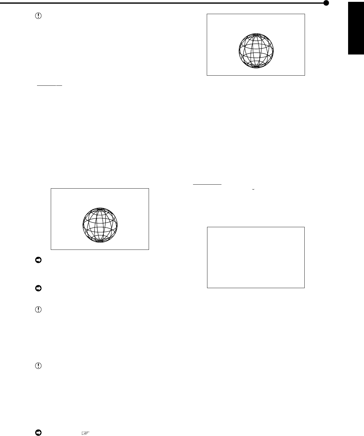
25
ENGLISH
•••••••••••••••••••••••••••••••••••••••••••••••••••••••••••••••••••••••••••••••••••••••••••••••••••••••••••••••••••••• Basic Operations
“SUB” is appeared on the screen when
“PARTITION” is selected on “HDD SETTING” of the
<INITIALIZATION> screen.
10-2. (To change the search type • • • )
Turn the JOG dial to select “SEARCH TYPE” and turn the
SHUTTLE ring clockwise.
• The background of the setting item changes to red and
flashes. Turn the JOG dial to display the desired search menu
and confirm.
• Setting ( default : “TIME DATE” )
“TIME DATE”, “INDEX”, “ALARM INDEX”, “ALARM SKIP”,
“ALARM LIST”
11. When the setting is complete, turn the SHUTTLE ring
counterclockwise.
• The display returns to the <TIME DATE SEARCH> screen
and the cursor appears on the left of the search date.
12. Turn the JOG dial to select “EXECUTE(FORWARD)” and
turn the SHUTTLE ring clockwise.
• When the TIME DATE SEARCH is executed, the video of the
set date/time (or the video closest to the search) will appear
in still frame.
• The search result will appear using SPLIT9 screen when
“ALL” is selected in “SELECTION CAMERA NUMBER” of the
<SEARCH SELECTION> screen. If a camera number has been
selected individually, the still frame will be displayed in full
screen.
<TIME DATE SEARCH>
>>
03-03-2004 21:25:40
EXECUTE(FORWARD)
MAIN
START 02-02-2004 00:00:00
END 04-04-2004 12:30:15
PUSH SEARCH KEY FOR
SEARCH SELECTION
When there is no recording of the set time, the
video of the closest time and date for the set cam-
era number will be displayed in still frame.
Depending on the recording condition, TIME
DATE SEARCH may not operate correctly.
To display full screen view by selecting a cam-
era number from the SPLIT9 screen of the search
result when “ALL” is selected in the “SELECTION
CAMERA NUMBER” setting, press the SEARCH
button to clear the SEARCH menu and press the
desired camera number button. The desired video
is displayed in full screen.
Press the camera number buttons during still
image playback to call up search mode. The search
mode status may continue for several hours if the
number of a camera with a small number of recorded
images has been specified. When not required,
press the STOP button to cancel the search status.
13. To playback the searched image.
• Press either the PLAY button or the PAUSE button.
For playback, see “Various playback func-
tions”, pages 65,66.
03-03-2004 21:25:40
3
PLAY
14. To stop playback/still frame playback, press the STOP
button.
• The display returns to the normal screen.
15. Press the SEARCH button twice to clear the <SEARCH
SELECTION> screen.
■ LANGUAGE SELECTION
With this unit, the menu screen display can be selected
from 6 languages. As “ENGLISH” is selected for the initial
setting, please perform setting according to the following
procedure if you want to select a language other than “ENG-
LISH”.
Setting ( default : “ENGLISH” )
“ENGLISH”, “FRANCAIS”, “DEUTSCH”,
“ESPAÑOL”, “
P
y
CCK
NN
”, “ITALIANO”
1. Press the SET UP button
}
<SETTINGS>
}
Select
“LANGUAGE SELECTION” in the <INITIAL SET UP/
INFORMATION> screen and display the desired setting.
<LANGUAGE SELECTION>
>>
LANGUAGE ENGLISH
JOG :SELECT
SHUTTLE>>:EXECUTE
2. Turn the SHUTTLE ring counterclockwise or press the SET
UP button.
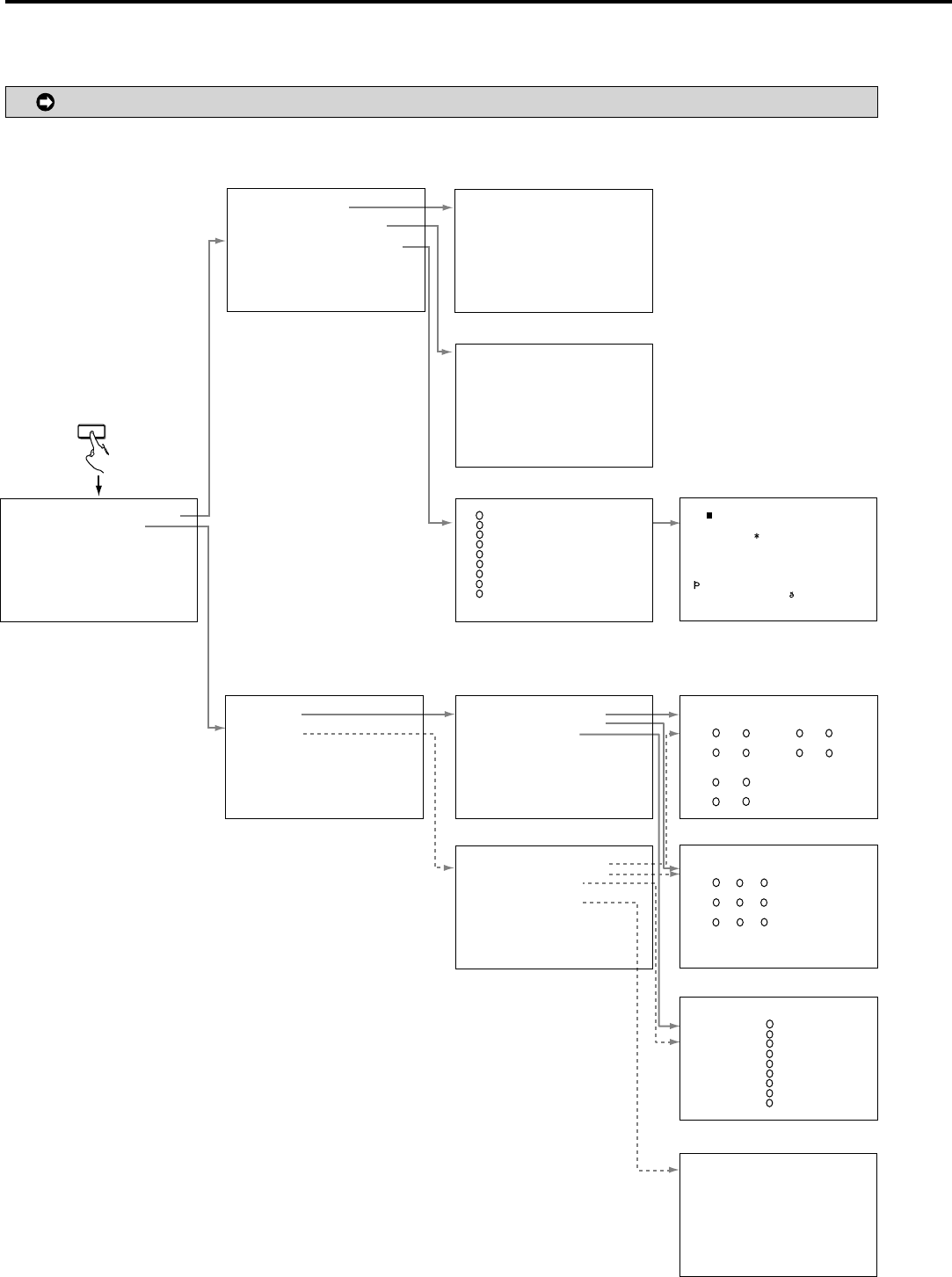
26
••••••••••••••••••••••••••••••••••••••••••••••••••••••••••••••••••••••••••••••••••••••••••••••••••••••••••••••••••••••••••••••••••••••••••••
Menu functions
<SEQUENCE SETTING>
SEQUENCE NUMBER TIME
>>
1 2S
2 2S
3 2S
4 2S
5 2S
6 2S
7 2S
8 2S
9 2S
SPLIT4 abc 2S
9
7
456
1
2
3
8
9
1
23
7
4
56
1
2
3
8
9
7
4
5
6
1
2
3
8
9
7
4
5
6
1
2
3
8
-
´´´´´
´
ˆ˜˜
<SETTINGS>
>>
TIME DATE/DISPLAY SETTINGS
MPX DISPLAY SETTINGS
MOTION DETECTION SETTINGS
RECORD SETTINGS
TIMER PROGRAM SETTINGS
INITIAL SET UP/INFORMATION
QUICK SETTINGS
MEMO:
<TIME DATE/DISPLAY SETTINGS>
>>
TIME DATE ADJUST
DISPLAY MODE 1
CLOCK LOCATION SETTING
CAMERA DISPLAY NUMBER
CAMERA TITLE/MEMO SETTING
DUPLEX MODE DISPLAY BOTTOM
<MODE 1>
01-01-2004 00:00:00
<TIME DATE ADJUST>
>>
DAYLIGHT SAVING OFF
DAY 01
MONTH 01
YEAR 2004
TIME 00:00:00
DAYLIGHT SETTING
DAY OF WEEK MONTH TIME
IN SUN LAST MAR 01:00
OUT SUN LAST OCT 02:00
JOG :SELECT
SHUTTLE>>:EXECUTE
••••••••••••••••••••••••••••••••
• 01-01-2004 00:00:00 ••••••••••
••••••••••••••••••••••••••••••••
••••••••••••••••••••••••••••••••
••••••••••••••••••••••••••••••••
••••••••••••••••••••••••••••••••
••••••••••••••••••••••••••••••••
••••••••••••••••••••••••••••••••
••••••••••••••••••••••••••••••••
••••••••••••••••••••••••••••••••
••••••••••••••••••••••••••••••••
••••••••••••••••••••••••••••••••
<OUTPUT B>
>>
SPLIT4 SCREEN SETTING
SPLIT9 SCREEN SETTING
SEQUENCE SETTING
INTERLACE ON
SAME AS OUTPUT A
<MPX DISPLAY SETTINGS>
>>
OUTPUT A
OUTPUT B ON/OFF OFF
OUTPUT B
<OUTPUT A>
>>
SPLIT4 SCREEN SETTING
SPLIT9 SCREEN SETTING
SEQUENCE SETTING
INTERLACE ON
SUB MENU (1)
MAIN MENU
SUB MENU (2)
SUB MENU (3)
SET UP
<SPLIT9 SCREEN SETTING>
>>
SPLIT9
( ) ( ) ( )
( ) ( ) ( )
( ) ( ) ( )
<SPLIT4 SCREEN SETTING>
>>
SPLIT4(a) SPLIT4(b)
( ) ( ) ( ) ( )
( ) ( ) ( ) ( )
SPLIT4(c)
( ) ( )
( ) ( )
<CHARACTERS>
••••••••••••••••
!
" #
$
%
& ' (
)
+ ,
-
.
/
: ;
<
=
>?
@
•••••••
0123456789••••••••••••••••••••
ABCDEFGHIJKLMNOPQRSTUVWXYZ••••
abcde
f
gh
i
j
k
l
mnopqrs
t
uvwxyz
••••
SHUTTLE<<:BACK
<CAMERA TITLE/MEMO SETTING>
>>
••••••••••••••••
••••••••••••••••
••••••••••••••••
••••••••••••••••
••••••••••••••••
••••••••••••••••
••••••••••••••••
••••••••••••••••
••••••••••••••••
MEMO ••••••••••••••••
SHUTTLE>>:CHARACTERS
<OUTPUT B>
>>
EXECUTE
SHUTTLE>>:EXECUTE,<<:CANCEL
<SPLIT4 SCREEN SETTING> Page 37
<SPLIT9 SCREEN SETTING> Pages 37,38
<OUTPUT B> Pages 35-38
<MPX DISPLAY SETTINGS> Pages 35-38 <OUTPUT A> Pages 35-38
<SEQUENCE SETTING> Page 38
<TIME DATE/DISPLAY SETTINGS>
Pages 19-21, 32-34 <TIME DATE ADJUST> Pages 20,21
<CLOCK LOCATION SETTING> Page 32
<CHARACTERS> Page 33
<CAMERA TITLE/MEMO SETTING>
Pages 32,33
<OUTPUT B> Page 37
ÀÁÂÃÄÅÆÇÈÉÊËÌÍÎÏDÑÒÓÔÕÖXØÙÚÛÜY
ß••••••••••••••••••••••••••••
àaaaäåæçèeêëìÍîï ñòoôoö÷øùuûüy
pÿ••••••••••••••••••••••••••••
■ MENU SETTING
You can set the basic settings for this unit in the MENU SETTING. Refer to pages shown below for details.
During playback, recording, pre-alarm recording stand-by mode you cannot change setting of some MENUs.

27
•••••••••••••••••••••••••••••••••••••••••••••••••••••••••••••••••••••••••••••••••••••••••••••••••••••••••••••••••••••••••••• Operations
ENGLISH
9
7
4
5
6
1
2
3
8
9
7
4
5
6
1
2
3
8
9
7
456
12
3
8
1
9
7
456
12
3
8
9
7
456
12
38
9
7
456
12
38
#1
#1
• • •••••••••• ••••
• • •••••••••• ••••
• • •••••••••• ••••
• • •••••••••• ••••
• • •••••••••• ••••
• • •••••••••• ••••
• • •••••••••• ••••
• • •••••••••• ••••
• • •••••••••• ••••
• • •••••••••• ••••
• • •••••••••• ••••
• • •••••••••• ••••
<MOTION DETECTION SETTINGS>
>>
SELECTION CAMERA NUMBER
DETECTION MASK SETTING
SENSITIVITY HIGH••<<<LOW
MOTION THRESHOLD 5
TEST MODE
<RECORD SETTINGS>
>>
ALARM SETTING
RECORD SETTING
ALARM REC DURATION 5S
PRE ALARM REC ( S ) S
MOTION DET REC ALARM
<SETTINGS>
>>
TIME DATE/DISPLAY SETTINGS
MPX DISPLAY SETTINGS
MOTION DETECTION SETTINGS
RECORD SETTINGS
TIMER PROGRAM SETTINGS
INITIAL SET UP/INFORMATION
QUICK SETTINGS
MEMO:
SUB MENU (1)
MAIN MENU
SUB MENU (2)
<RECORD SETTING A>
>>
ALARM CH
NO PPS GRADE A-PPS A-GRADE
2.5P STD 2.5P STD
2.5P STD 2.5P STD
2.5P STD 2.5P STD
2.5P STD 2.5P STD
2.5P STD 2.5P STD
2.5P STD 2.5P STD
2.5P STD 2.5P STD
2.5P STD 2.5P STD
2.5P STD 2.5P STD
<ESTD REC> D H M %
<TIMER PROGRAM SETTINGS>
>>
SELECTED PATTERN P1-SET
HOLIDAY SETTING
REC MODE A
REC MODE B
REC MODE C
REC MODE D
ALARM REC DURATION 5S
<REC MODE A>
>>
ALARM SETTING
RECORD SETTING
PRE ALARM REC ( S ) S
MOTION DET REC ALARM
<TIMER PROGRAM> P1
DW START END MODE MD
>>
1 --- --:-- --:-- ---- -
2 --- --:-- --:-- ---- -
3 --- --:-- --:-- ---- -
4 --- --:-- --:-- ---- -
5 --- --:-- --:-- ---- -
6 --- --:-- --:-- ---- -
7 --- --:-- --:-- ---- -
8 --- --:-- --:-- ---- -
SPL SAT-SUN
<RECORD SETTING>
>>
ALARM CH
NO PPS GRADE A-PPS A-GRADE
2.5P STD 2.5P STD
2.5P STD 2.5P STD
2.5P STD 2.5P STD
2.5P STD 2.5P STD
2.5P STD 2.5P STD
2.5P STD 2.5P STD
2.5P STD 2.5P STD
2.5P STD 2.5P STD
2.5P STD 2.5P STD
<ESTD REC> D H M %
SET UP
& & &&&&&&&&&& &&&&
& & &&&&&&&&&& &&&&
& & &&&&&&&&&& &&&&
& & &&&&&&&&&& &&&&
& & &&&&&&&&&& &&&&
& & &&&&&&&&&& &&&&
& & &&&&&&&&&& &&&&
& & &&&&&&&&&& &&&&
& & &&&&&&&&&& &&&&
& & &&&&&&&&&& &&&&
& & &&&&&&&&&& &&&&
& & &&&&&&&&&& &&&&
<ALARM SETTING A>
>>
ALARM CH
ALARM RECORD CAMERA TRIGGER
1 -------- EXT
2 - ------- EXT
3 -- ------ EXT
4 --- ----- EXT
5 ---- ---- EXT
6 ----- --- EXT
7 ------ -- EXT
8 ------- - EXT
9 -------- EXT
EMR
<HOLIDAY SETTING>
--/-- --/-- --/-- --/--
--/-- --/-- --/-- --/--
--/-- --/-- --/-- --/--
--/-- --/-- --/-- --/--
--/-- --/-- --/-- --/--
DAY/MONTH
<ALARM SETTING>
>>
ALARM CH
ALARM RECORD CAMERA TRIGGER
1 -------- EXT
2 - ------- EXT
3 -- ------ EXT
4 --- ----- EXT
5 ---- ---- EXT
6 ----- --- EXT
7 ------ -- EXT
8 ------- - EXT
9 -------- EXT
EMR
SUB MENU (3)
<DETECTION MASK SETTING> Page 39
<TEST MODE> Page 40
<MOTION DETECTION SETTINGS>
Pages 39,40
<RECORD SETTINGS> Pages 21-23,41-43 <ALARM SETTING> Pages 41,42
<RECORD SETTING> Pages 22,23,41,42
<HOLIDAY SETTING> Page 46
<TIMER PROGRAM SETTINGS> Pages 44-46
<REC MODE A> ~ <REC MODE D> Page 46
<TIMER PROGRAM> Pages 44,45
<RECORD SETTING A> ~
<RECORD SETTING D> Page 46
CAUTION : For <ESTD REC>,
see “Continuous recording time table” ,
pages 83,84.
#1. Appears when “PARTITION”
is set is on the screen.
<ALARM SETTING A> ~
<ALARM SETTING D> Page 46

28
••••••••••••••••••••••••••••••••••••••••••••••••••••••••••••••••••••••••••••••••••••••••••••••••••••••••••••••••••••••••••••••••••••••••••••
Menu functions (continued)
#1. Appears when “PARTITION” is set on the screen.
<SERVICE PORT SETTING> Page 53
<ALARM NOTIFICATION SETTING>
Pages 53,54
<INITIAL SET UP/INFORMATION>
>>
HDD SETTINGS
AUDIO RECORDING OFF
REAR TERMINAL SETTINGS
COMMUNICATION PORT SETTINGS
INFORMATION/SERVICE
PASSWORD
LANGUAGE SELECTION
<HDD SETTINGS>
>>
HDD REPEAT REC MAIN ON
HDD REPEAT REC SUB OFF
HDD REPEAT PLAY OFF
IM-CHECK PLAY OFF
SEQUENTIAL PLAY OFF
<REAR TERMINAL SETTINGS>
>>
MODE OUT 1 OFF
MODE OUT 2 OFF
MODE OUT 3 OFF
MODE OUT 4 OFF
MODE OUT 5 OFF
KEY SOUND ON
BUZZER OFF
REMAIN HDD MAIN-10
%
CALL OUT SETTINGS
EMERGENCY REC DURATION 10M
<CALL OUT SETTINGS>
>>
HDD MAIN REMAIN OFF
HDD MAIN FULL OFF
HDD SUB REMAIN OFF
HDD SUB FULL OFF
<COMMUNICATION PORT SETTINGS>
>>
RS-232C
ETHERNET
<RS-232C>
MODE REMOTE A
>>
SETTINGS
<SETTINGS>
>>
TIME DATE/DISPLAY SETTINGS
MPX DISPLAY SETTINGS
MOTION DETECTION SETTINGS
RECORD SETTINGS
TIMER PROGRAM SETTINGS
INITIAL SET UP/INFORMATION
QUICK SETTINGS
MEMO:
SUB MENU (1)
MAIN MENU
SUB MENU (2)
SUB MENU (3)
<RS-232C SETTINGS>
>>
TRANSMISSION MODE 9600
DATA BIT LENGTH 8BIT
PARITY BIT NONE
STOP BIT LENGTH 1BIT
DELIMITER CR
<ETHERNET>
>>
IP ADDRESS 192.168.000.100
SUB NET MASK 255.255.255.000
GATEWAY 000.000.000.000
E-MAIL ADDRESS
SERVICE PORT SETTING
ALARM NOTIFICATION SETTING
<MAC ADDRESS>
08-00-70-2E-3F-FF
PLEASE PRESS SET UP BUTTON
TO APPLY NEW SETTING
<ALARM NOTIFICATION SETTING>
NO IP ADDRESS TARGET OWN
>>
1 000.000.000.000•55111 01111
2 000.000.000.000•55111 01112
3 000.000.000.000•55111 01113
4 000.000.000.000•55111 01114
5 000.000.000.000•55111 01115
WARNING OFF
ALARM SENS OFF
REC MODE OFF
RETRY TIME 10S
<SERVICE PORT SETTING>
>>
WEB •00080
USER ACCESS 53705
SUPER USER 53706
LIVE USER1 53707
LIVE USER2 53708
LIVE USER3 53709
LIVE USER4 53710
<E-MAIL ADDRESS> Page 52
<E-MAIL ADDRESS>
SMTP SERVER
RECORDER ID
USER ADDRESS
1
2
3
4
5
SUB MENU (4)
SET UP
#1
#1
<INITIAL SET UP/INFORMATION>
Pages 47-58 <HDD SETTINGS> Pages 47,48
<REAR TERMINAL SETTINGS> Pages 49-51 <CALL OUT SETTINGS> Pages 50,51
<COMMUNICATION PORT SETTINGS>
Pages 51-54 <RS-232C> Pages 51,52 <RS-232C SETTINGS> Page 52
<
ETHERNET
> Pages 52-54

29
•••••••••••••••••••••••••••••••••••••••••••••••••••••••••••••••••••••••••••••••••••••••••••••••••••••••••••••••••••••••••••• Operations
ENGLISH
<INITIAL SET UP/INFORMATION>
>>
HDD SETTINGS
AUDIO RECORDING OFF
REAR TERMINAL SETTINGS
COMMUNICATION PORT SETTINGS
INFORMATION/SERVICE
PASSWORD
LANGUAGE SELECTION
<SETTINGS>
>>
TIME DATE/DISPLAY SETTINGS
MPX DISPLAY SETTINGS
MOTION DETECTION SETTINGS
RECORD SETTINGS
TIMER PROGRAM SETTINGS
INITIAL SET UP/INFORMATION
QUICK SETTINGS
MEMO:
SUB MENU (1) SUB MENU (2)
MAIN MENU
<INFORMATION/SERVICE> (1/2)
>>
HDD INFORMATION
CFC INFORMATION
WARNING LOG LIST
RESET TO FACTORY SETTINGS
MAIN HDD DATA CLEAR
SUB HDD DATA CLEAR
CFC DATA CLEAR
<INFORMATION/SERVICE> (2/2)
ELAPSED TIME: SYSTEM 3H
HDD SETTING PARTITION
PARTITION SIZE 10
%
<HDD INFORMATION>
INTERNAL HDD
MASTER: HDD(250GB)
SLAVE : NONE
MAIN START 01-01-2004 00:00:00
END 01-01-2004 00:00:05
SUB START 01-01-2004 00:00:00
END 01-01-2004 00:00:05
<CFC INFORMATION>
CFC
CAPACITY 128MB
START ---------- --:--:--
END ---------- --:--:--
SUB MENU (3)
<RESET TO FACTORY SETTINGS>
>>
EXECUTE
SHUTTLE>>:EXECUTE,<<:CANCEL
<WARNING LOG LIST>
NO DATE TIME WARNING
>>
0001 01-01-04 00:00:00 ALM ON
#1
#1
SET UP
#1
<QUICK SETTINGS>
>>
LOAD SETTING DATA FROM CFC
SAVE SETTING DATA TO CFC
<QUICK SETTINGS> Page 59
#1. Appears when “PARTITION” is set on the screen.
<INITIAL SET UP/INFORMATION>
Pages 47-58 <INFORMATION/SERVICE> 2/2<INFORMATION/SERVICE> 1/2
Pages 54-56
<HDD INFORMATION> Page 54
<CFC INFORMATION> Page 54
<WARNING LOG LIST> Pages 54,55
<RESET TO FACTORY SETTINGS> Page 55
<SETTING DATA LOADING>
>>
EXECUTE
SHUTTLE>>:EXECUTE,<<:BACK
<SETTING DATA LOADING> Page 59
<SETTING DATA SAVING>
>>
EXECUTE
SHUTTLE>>:EXECUTE,<<:BACK
<SETTING DATA SAVING> Page 59
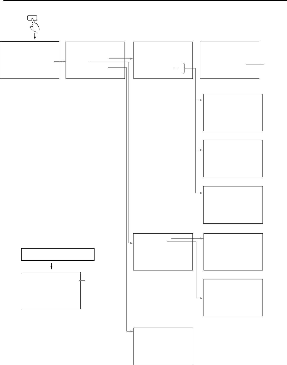
30
••••••••••••••••••••••••••••••••••••••••••••••••••••••••••••••••••••••••••••••••••••••••••••••••••••••••••••••••••••••••••••••••••••••••••••
Menu functions (continued)
SUB MENU (3)
MAIN MENU SUB MENU (1) SUB MENU (2)
<MAIN HDD DATA CLEAR>
PUSH WARNING RESET KEY
FOR 1 SECOND TO CLEAR
<SUB HDD DATA CLEAR>
PUSH WARNING RESET KEY
FOR 1 SECOND TO CLEAR
<CFC DATA CLEAR>
PUSH WARNING RESET KEY
FOR 1 SECOND TO CLEAR
<INITIALIZATION>
>>
HDD SETTING PARTITION
PARTITION SIZE 10
%
POWER OFF
INITIALIZATION
ALL DATA WILL BE ERASED
WHEN PROCEED INITIALIZATION
REC/STOP + POWER button
<LANGUAGE SELECTION>
>>
LANGUAGE ENGLISH
JOG :SELECT
SHUTTLE>>:EXECUTE
<PASSWORD>
>>
OPERATION CONTROL
HDD DATA CLEAR
<INITIAL SET UP/INFORMATION>
>>
HDD SETTINGS
AUDIO RECORDING OFF
REAR TERMINAL SETTINGS
COMMUNICATION PORT SETTINGS
INFORMATION/SERVICE
PASSWORD
LANGUAGE SELECTION
<SETTINGS>
>>
TIME DATE/DISPLAY SETTINGS
MPX DISPLAY SETTINGS
MOTION DETECTION SETTINGS
RECORD SETTINGS
TIMER PROGRAM SETTINGS
INITIAL SET UP/INFORMATION
QUICK SETTINGS
MEMO:
<INFORMATION/SERVICE> (1/2)
>>
HDD INFORMATION
CFC INFORMATION
WARNING LOG LIST
RESET TO FACTORY SETTINGS
MAIN HDD DATA CLEAR
SUB HDD DATA CLEAR
CFC DATA CLEAR
<INFORMATION/SERVICE> (2/2)
ELAPSED TIME: SYSTEM 3H
HDD SETTING PARTITION
PARTITION SIZE 10
%
#1 #
1
#1
#1
SET UP
<PASSWORD SETTING>
FIRST SECOND
>>
1 ---- ----
2 ---- ----
3 ---- ----
PRESS WARNING RESET BUTTON
TO CLEAR PASSWORD
SHUTTLE>>:TO SET PASSWORD
<PASSWORD SETTING> Pages 56-58
<PASSWORD SETTING>
FIRST SECOND
>>
4 ---- ----
PRESS WARNING RESET BUTTON
TO CLEAR PASSWORD
SHUTTLE>>:TO SET PASSWORD
<PASSWORD SETTING> Pages 56-58
<SUB HDD DATA CLEAR> Pages 55,56
<CFC DATA CLEAR> Pages 55,56
<LANGUAGE SELECTION> Page 25
<INITIAL SET UP/INFORMATION>
Pages 47-58 <INFORMATION/SERVICE> 1/2 Pages 54-56 <INFORMATION/SERVICE> 2/2
<MAIN HDD DATA CLEAR> Pages 55,56
<PASSWORD> Pages 56-58
#1. Appears when “PARTITION” is set on the screen.
<INITIALIZATION> Pages 74,75
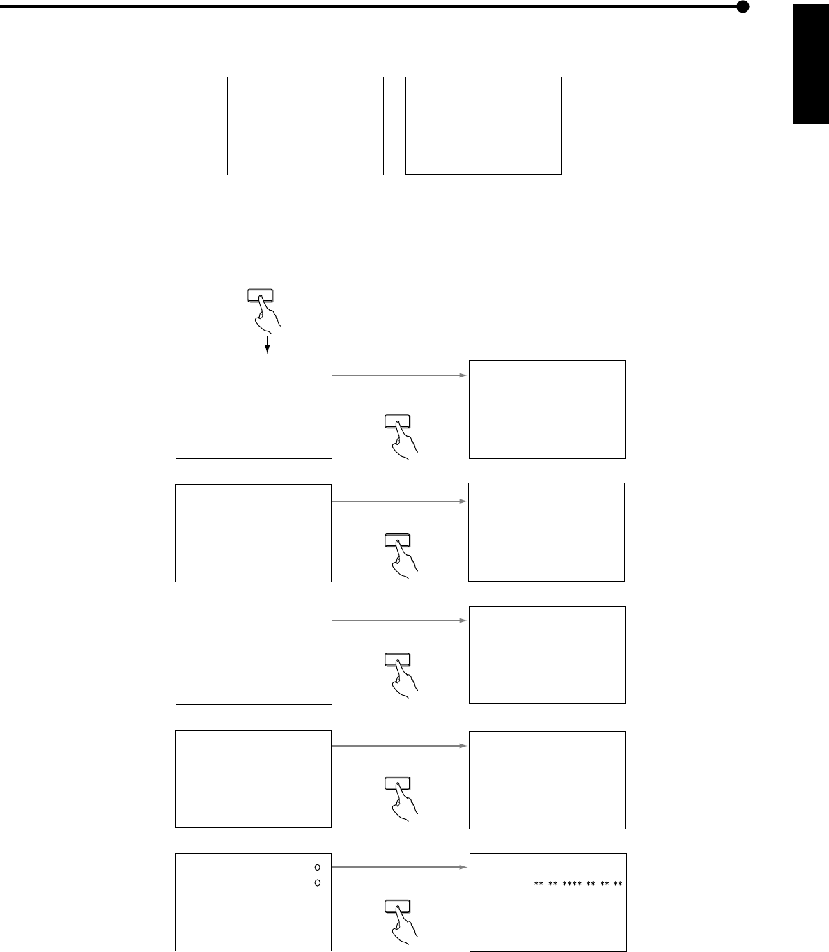
31
•••••••••••••••••••••••••••••••••••••••••••••••••••••••••••••••••••••••••••••••••••••••••••••••••••••••••••••••••••••••••••• Operations
ENGLISH
<COPY> <RESTORE>
1
2
SEARCH
SEARCH
SEARCH
SEARCH
SEARCH
SEARCH
<TIME DATE SEARCH>
>>
01-01-2004 00:00:00
EXECUTE(FORWARD)
MAIN
START ---------- --:--:--
END ---------- --:--:--
PUSH SEARCH KEY FOR
SEARCH SELECTION
MAIN MENU
<INDEX SEARCH>
>>
INDEX 01
EXECUTE(FORWARD)
EXECUTE(REVERSE)
MAIN
START ---------- --:--:--
END ---------- --:--:--
PUSH SEARCH KEY FOR
SEARCH SELECTION
<ALARM INDEX SEARCH>
>>
INDEX 01
EXECUTE(FORWARD)
EXECUTE(REVERSE)
MAIN
START ---------- --:--:--
END ---------- --:--:--
PUSH SEARCH KEY FOR
SEARCH SELECTION
<ALARM LIST SEARCH>
>>
00004 01-01-2004 00:00:04 1
00003 01-01-2004 00:00:03 EMR
00002 01-01-2004 00:00:02 1
00001 01-01-2004 00:00:01 EMR
PUSH SEARCH KEY
<ALARM SKIP SEARCH>
>>
EXECUTE(FORWARD)
EXECUTE(REVERSE)
PUSH SEARCH KEY FOR
SEARCH SELECTION
<SEARCH SELECTION>
SEARCH TYPE TIME DATE
>>
SELECTION CAMERA NUMBER ALL
PLAYBACK DEVICE MAIN
MAIN
START ---------- --:--:--
END ---------- --:--:--
<SEARCH SELECTION>
SEARCH TYPE INDEX
>>
PLAYBACK DEVICE MAIN
MAIN
START ---------- --:--:--
END ---------- --:--:--
SUB MENU (1)
<SEARCH SELECTION>
SEARCH TYPE ALARM LIST
>>
SELECTION CAMERA NUMBER ALL
DATE/TIME - - : :
PLAYBACK DEVICE SUB
SUB
START 01-01-2004 00:00:00
END 01-01-2004 00:00:05
<COPY>
>>
DIRECTION MAIN HDD}CFC
MODE OVERWRITE
TRANSFER PERIOD START•END
START 01-01-2004 00:00:00
END 01-01-2004 00:00:10
EXECUTE
<RESTORE>
>>
DIRECTION CFC}MAIN HDD
MODE OVERWRITE
TRANSFER PERIOD START•END
START 01-01-2004 00:00:00
END 01-01-2004 00:00:10
EXECUTE
MAIN MENU
<COPY> Pages 72,73 <RESTORE> Pages 72,73
<TIME DATE SEARCH> Pages 24,25
<INDEX SEARCH> Pages 68,69 <SEARCH SELECTION> Page 67
<SEARCH SELECTION> Page 67
<SEARCH SELECTION>
SEARCH TYPE ALARM INDEX
>>
SELECTION CAMERA NUMBER ALL
PLAYBACK DEVICE MAIN
MAIN
START ---------- --:--:--
END ---------- --:--:--
<SEARCH SELECTION> Page 67
<ALARM INDEX SEARCH> Pages 68,69
<ALARM SKIP SEARCH> Pages 69,70
<ALARM LIST SEARCH> Pages 70,71 <SEARCH SELECTION> Page 67
<SEARCH SELECTION>
SEARCH TYPE ALARM SKIP
>>
SELECTION CAMERA NUMBER ALL
PLAYBACK DEVICE MAIN
MAIN
START ---------- --:--:--
END ---------- --:--:--
<SEARCH SELECTION> Page 67
■ SEARCH SELECTION MENU
■ COPY MENU

••••••••••••••••••••••••••••••••••••••••••••••••••••••••••••••••••••••••••••••••••••••••••••••••••••••••••••••••••••••••••••••••••••••••••••
32
■ TIME DATE ADJUST
See pages 20,21.
■ DISPLAY MODE
Display format of the date and current time can be set.
<TIME DATE/DISPLAY SETTINGS>
TIME DATE ADJUST
>>
DISPLAY MODE 1
CLOCK LOCATION SETTING
CAMERA DISPLAY NUMBER
CAMERA TITLE/MEMO SETTING
DUPLEX MODE DISPLAY BOTTOM
<MODE 1>
01-01-2004 00:00:00
Setting ( default : “1” )
“1” : Displays the date/month/year, current time.
“2” : Displays the date/month/year, day of week, current
time, playback interval (single screen playback only).
“3” : Displays the date/month/year, day of the week,
time, playback interval (single screen playback only),
HDD usage space ( see page 21) (during recording/
playback only if REMAIN HDD is set to MAIN, SUB),
and alarm recording number (during alarm recording/
playback).
“4” : No indication.
(When alarm signal is input, displays the date/month/
year, day of week, current time and alarm recording
number (during alarm recording/playback)).
“5” : No indication.
(When warning signal is input, displays warning mes-
sage.)
“6” : No indication.
01-01-2004 00:00:00
01-01-2004 THU
00:00:00 12.5P
<MODE 1>
<MODE 2>
01-01-2004 THU
00:00:00 12.5P 99% A00001
<MODE 3>
1. Press the SET UP button
}
<SETTINGS>
}
Select
“DISPLAY MODE” in the <TIME DATE/DISPLAY SETTINGS>
screen. Display the desired setting and confirm.
2. Turn the SHUTTLE ring counterclockwise or press the SET
UP button.
■ CLOCK LOCATION SETTING
The display positions of the date, current time, camera
number and title can be set.
1. Press the SET UP button
}
<SETTINGS>
}
Select “CLOCK
LOCATION SETTING” in the <TIME DATE/DISPLAY
SETTINGS> screen and turn the SHUTTLE ring clockwise.
• The <CLOCK LOCATION SETTING> screen appears.
••••••••••••••••••••••••••••••••
• 01-01-2004 00:00:00 ••••••••••
••••••••••••••••••••••••••••••••
••••••••••••••••••••••••••••••••
••••••••••••••••••••••••••••••••
2. Use the , , and buttons to move the time and date to
the desired display position and turn the SHUTTLE ring
clockwise.
• The setting is confirmed.
The date, the present time, etc. on a screen can be
moved to right and left and the upper and lower sides
by pushing , , and button.
The display can be moved continuously to the right
by turning the JOG dial clockwise, to the left by turning
it counterclockwise.
3. Turn the SHUTTLE ring counterclockwise or press the SET
UP button.
■ CAMERA DISPLAY
Setting can be made to display the title and memo set in
“CAMERA TITLE/MEMO SETTING”, camera number
only, etc.
<TIME DATE/DISPLAY SETTINGS>
TIME DATE ADJUST
DISPLAY MODE 1
CLOCK LOCATION SETTING
>>
CAMERA DISPLAY NUMBER
CAMERA TITLE/MEMO SETTING
DUPLEX MODE DISPLAY BOTTOM
<MODE 1>
01-01-2004 00:00:00
Setting ( default : “NUMBER” )
“NUMBER” : Only the camera number is displayed.
“TITLE” : The title set in “CAMERA TITLE/MEMO SET-
TING” is displayed. The title can also be recorded along
with the video.
“COMMENT” : The comment inputted by RS-232C con-
nection is displayed.
“NONE” : No display.
1. Press the SET UP button
}
<SETTINGS>
}
Select
“CAMERA DISPLAY” in the <TIME DATE/DISPLAY
SETTINGS> screen. Display the desired setting and confirm.
2. Turn the SHUTTLE ring counterclockwise or press the SET
UP button.
■ CAMERA TITLE/MEMO SETTING
Titles can be set individually to each connected camera.
When selecting “TITLE” in “CAMERA DISPLAY”, the title,
such as the location of the camera, will appear on the
screen for an easy-to-understand monitoring system.
The maximum number of characters for the title is
16. The number of characters displayed on the screen
all 16 for single screen, first 10 for SPLIT4, first 6 for
SPLIT9.
Example : When setting titles of “ENTRANCE” and
“COUNTER” to camera number “
1
” and “
4
”, respec-
tively, and setting memo of “BANK”.
<TIME DATE/DISPLAY SETTINGS>
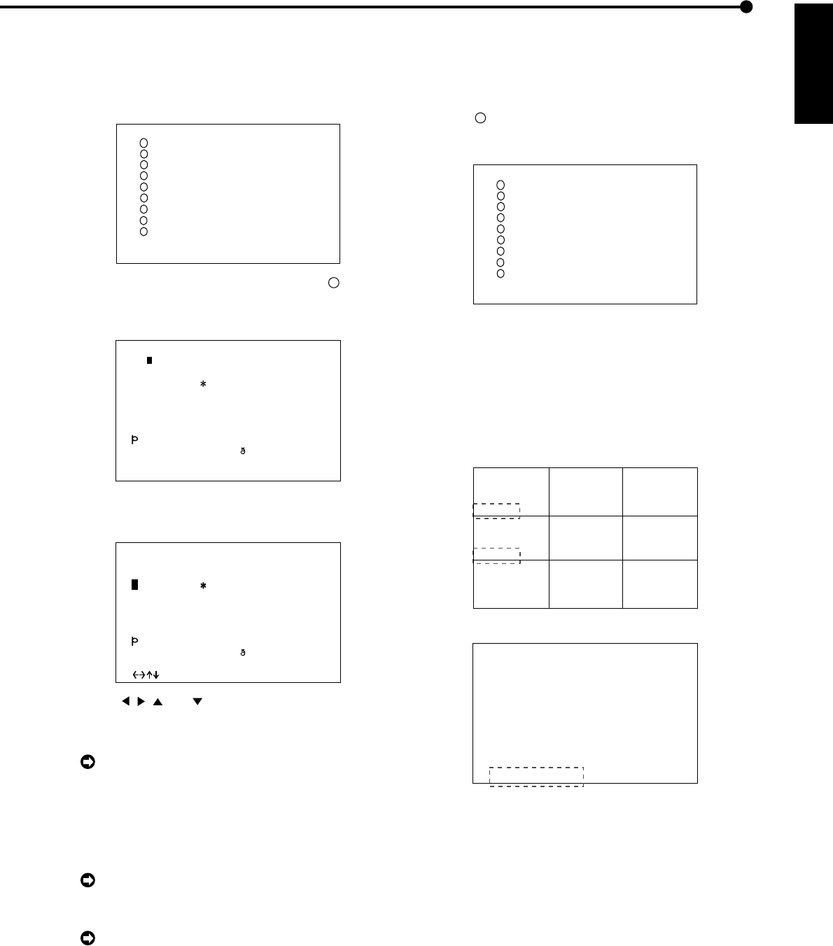
ENGLISH
33
•••••••••••••••••••••••••••••••••••••••••••••••••••••••••••••••••••••••••••••••••••••••••••••••••••••••••••••••••••••••••••• Operations
1. Press the SET UP button
}
<SETTINGS>
}
Select
“CAMERA TITLE/MEMO SETTING” in the <TIME DATE/
DISPLAY SETTINGS> screen and turn the SHUTTLE ring
clockwise.
• The <CAMERA TITLE/MEMO SETTING> screen appears.
<CAMERA TITLE/MEMO SETTING>
9
7
4
5
6
1
2
3
8
<CAMERA TITLE/MEMO SETTING>
>>
••••••••••••••••
••••••••••••••••
••••••••••••••••
••••••••••••••••
••••••••••••••••
••••••••••••••••
••••••••••••••••
••••••••••••••••
••••••••••••••••
MEMO ••••••••••••••••
SHUTTLE>>:CHARACTERS
2. Turn the JOG dial to select camera number “
1
” and turn
the SHUTTLE ring clockwise.
• The <CHARACTERS> screen appears and the character on
the very left of the string is displayed in reversed color.
ÀÁÂÃÄÅÆÇÈÉÊËÌÍÎÏDÑÒÓÔÕÖXØÙÚÛÜY
ß••••••••••••••••••••••••••••
àaaaäåæçèeêëìÍîï ñòoôoö÷øùuûüy
pÿ••••••••••••••••••••••••••••
<CHARACTERS>
••••••••••••••••
!
" #
$
%
& ' (
)
+ ,
-
.
/
: ;
<
=
>?
@
•••••••
0123456789••••••••••••••••••••
ABCDEFGHIJKLMNOPQRSTUVWXYZ••••
abcde
f
gh
i
j
k
l
mnopqrs
t
uvwxyz
••••
SHUTTLE<<:BACK
-
´´´´´
´
ˆ˜˜
3. Turn the SHUTTLE ring clockwise.
• The very left character “_” (space) on the bottom row of the
available characters turns red and flashes.
ÀÁÂÃÄÅÆÇÈÉÊËÌÍÎÏDÑÒÓÔÕÖXØÙÚÛÜY
ß••••••••••••••••••••••••••••
àaaaäåæçèeêëìÍîï ñòoôoö÷øùuûüy
pÿ••••••••••••••••••••••••••••
<CHARACTERS>
••••••••••••••••
!
" #
$
%
& ' (
)
+ ,
-
.
/
: ;
<
=
>?
@
•••••••
0123456789••••••••••••••••••••
ABCDEFGHIJKLMNOPQRSTUVWXYZ••••
abcde
f
gh
i
j
k
l
mnopqrs
t
uvwxyz
••••
:SELECT,SHUTTLE>>:CONFIRM
-
´´´´´
´
ˆ˜˜
4. Use the
, , and
buttons and the JOG dial to select
“E” and turn the SHUTTLE ring clockwise.
• “E” appears in reversed color on the very left of the string.
The JOG dial can be turned to continuously move
the cursor horizontally.
5. Turn the JOG dial clockwise to reverse display the character
on the right.
6. Repeat steps 3 ~ 5 to input “ENTRANCE” in the string.
To erase an inputted character, move the cursor to the
very left character “_” (space), turn the SHUTTLE ring
clockwise and confirm.
To change a character inputted in error :
1. While one of the characters in the string is displayed
in reversed color, turn the JOG dial to reverse display
the character to change.
2. Perform steps 3 and 4.
7. When completed with input, turn the SHUTTLE ring
counterclockwise.
• The display returns to the <CAMERA TITLE/MEMO
SETTING> screen.
8. Repeat steps 2 ~ 6 to input “COUNTER” in the camera
number “
4
”.
Example
<CAMERA TITLE/MEMO SETTING>
9
7
4
5
6
1
2
3
8
<CAMERA TITLE/MEMO SETTING>
ENTRANCE
••••••••••••••••
••••••••••••••••
>>
COUNTER
••••••••••••••••
••••••••••••••••
••••••••••••••••
••••••••••••••••
••••••••••••••••
MEMO ••••••••••••••••
SHUTTLE>>:CHARACTERS
9. When completed with input, turn the SHUTTLE ring
counterclockwise.
• The display returns to the <CAMERA TITLE/MEMO
SETTING> screen.
10. Repeat steps 2 ~ 7 to input “BANK” in MEMO.
11. Turn the SHUTTLE ring counterclockwise or press the SET
UP button.
03-03-2004 21:25:40
ENTRAN
COUNTE
Example <SPLIT9 SCREEN>
<SETTINGS>
>>
TIME DATE/DISPLAY SETTINGS
MPX DISPLAY SETTINGS
MOTION DETECTION SETTINGS
RECORD SETTINGS
TIMER PROGRAM SETTINGS
INITIAL SET UP/INFORMATION
QUICK SETTINGS
MEMO: BANK
Example <MEMO SETTING>

••••••••••••••••••••••••••••••••••••••••••••••••••••••••••••••••••••••••••••••••••••••••••••••••••••••••••••••••••••••••••••••••••••••••••••
34
■ DUPLEX MODE DISPLAY
Operation conditions such as PLAYBACK, COPY, REC
and ALARM REC (ALARM is displayed in red during
emergency recording), etc., can be displayed on the up-
per or lower portions of the screen.
<TIME DATE/DISPLAY SETTINGS>
TIME DATE ADJUST
DISPLAY MODE 1
CLOCK LOCATION SETTING
CAMERA DISPLAY NUMBER
CAMERA TITLE/MEMO SETTING
>>
DUPLEX MODE DISPLAY BOTTOM
<MODE 1>
01-01-2004 00:00:00
Setting ( default : “BOTTOM” )
“BOTTOM” : The operation condition is displayed on
the bottom of the screen.
“NONE” : The operation condition is not displayed.
“TOP” : The operation condition is displayed on the top
of the screen.
1. Press the SET UP button
}
<SETTINGS>
}
Select
“DUPLEX MODE DISPLAY” in the <TIME DATE/DISPLAY
SETTINGS> screen. Display the desired setting and confirm.
2. Turn the SHUTTLE ring counterclockwise or press the SET
UP button.
<TIME DATE/DISPLAY SETTINGS> (continued)
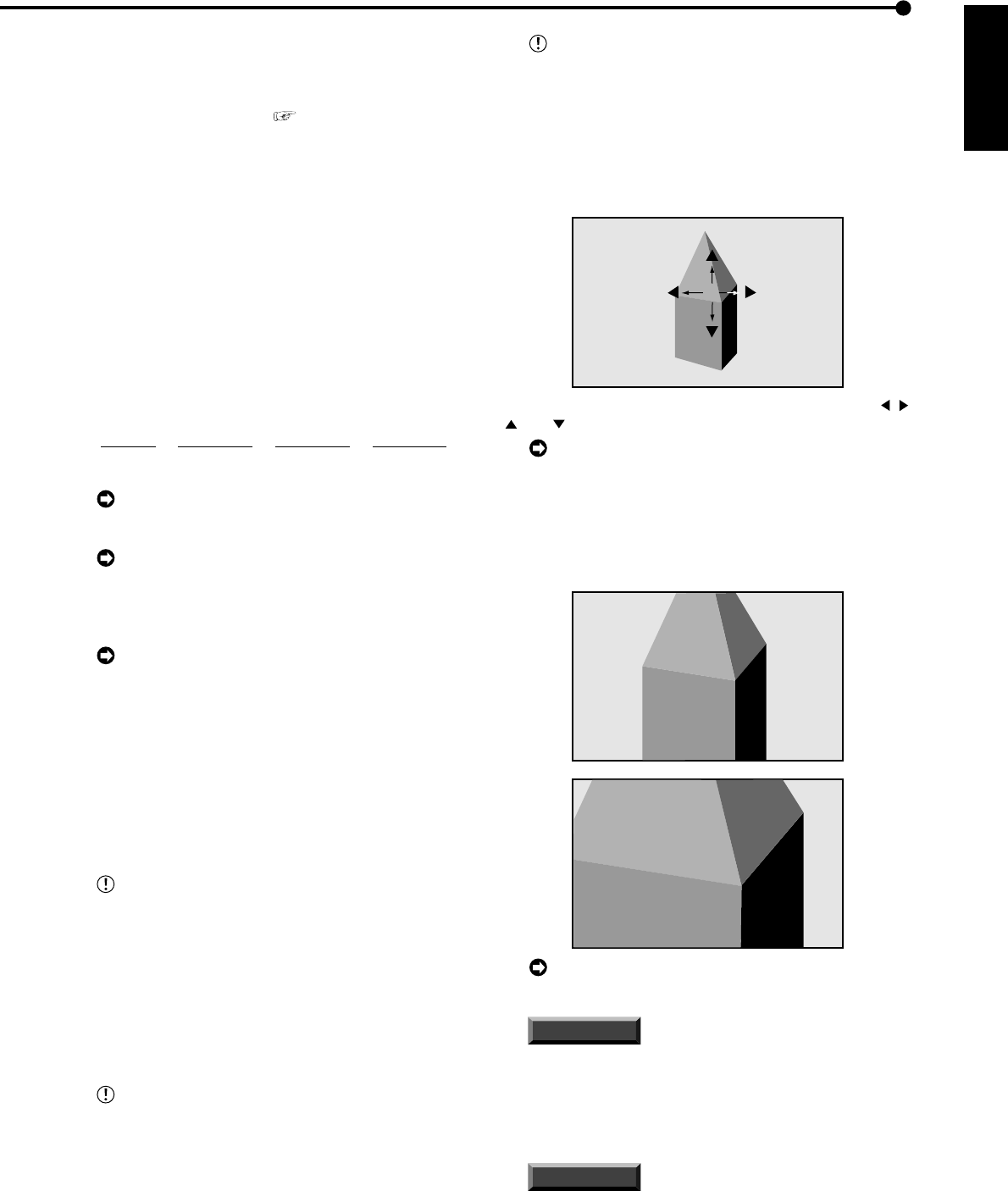
35
•••••••••••••••••••••••••••••••••••••••••••••••••••••••••••••••••••••••••••••••••••••••••••••••••••••••••••••••••••••••••••• Operations
ENGLISH
<MPX DISPLAY SETTINGS>
The multiplexer function of this unit allows the connected
camera video to be displayed using SPLIT4 screen and
SPLIT9 screens. It is also possible to set the order of the
camera number displayed. Basic operations of the multi-
plexer can also be found on see page 19.
■ Multiplexer function related button
operations/operation table
♦ Camera number button operations
When pressing a camera number button, the video of the cam-
era connected to that camera number terminal is displayed
using a single screen. Even during split/sequential screen dis-
play, video from any camera can be displayed using a single
screen by pressing the respective camera number button.
♦ SPLIT/SEQUENCE button operations
By pressing the SPLIT/SEQUENCE button, the display
modes shown below set in each split screen setting of the
multiplexer setting can be displayed in order.
Available modes
“SPLIT9”, “SPLIT4(a)”, “SPLIT4(b)”, “SPLIT4(c)”,
“SPLIT4 sequential”, “Single screen sequential”.
During playback, the underlined displayed modes
and single screen can be selected.
The split screen setting can be set using “SPLIT4
SCREEN SETTING” and “SPLIT9 SCREEN SET-
TING” in the <OUTPUT A> screen and <OUTPUT
B> screen respectively.
The update speed of camera video becomes
slower as the quantity of camera increases. Also,
when performing live communication by LAN via
Ethernet, the update speed may decrease.
To return the screen to single screen display
Pressing a camera number button (1 ~ 9) cancels the split/
sequential display and returns to the single screen display
of the pressed camera number button. Pressing the SPLIT/
SEQUENCE button again returns the screen to the split/
sequential display previous to cancelling.
When a menu screen is displayed, the single
screen display will not appear even when pressing a
camera number button (1 ~ 9). In this case, clear the
menu screen and then press a camera number but-
ton (1 ~ 9).
♦ ZOOM button operations
By pressing the ZOOM button in single screen display, the
displayed video can be viewed at 100%, 200% or 400%
magnification.
If the OUTPUT B indicator is turned off in the
screen of OUTPUT A, the ZOOM button will function.
The ZOOM button dose not function when the
OUTPUT B indicator illuminates by pressing the
OUTPUT B button.
The magnification display function can only be
set when in the single screen mode. The screen can
be moved vertically and horizontally with the magni-
fication centre point (X) as the axis by pressing the
MOVE buttons.
1. Press the ZOOM button during single screen display.
• “X1” appears on the top left the single screen display and
the magnification centre point (X) appears at the centre of
the screen.
X1
X
2. To shift the screen vertically or horizontally, press the
, ,
and
buttons.
The position of the magnification centre point is
stored even when the display screen is switched or
the power is turned off. This is convenient when the
point to magnify is determined in advance.
3. Press the ZOOM button.
• Pressing the button each time switches the magnification
in order of X2(200%), X4(400%), normal and X1(100%).
X2
X4
The magnification function can also be used dur-
ing playback of recorded contents.
INFORMATION
A black screen may appear when pausing recorded
video of multiple cameras in the single screen dis-
play mode and magnifying. In this case, display the
magnified screen by turning the JOG dial and for-
warding a frame.
INFORMATION
The magnification display function of this unit uses
digital magnification and screen details may appear
pixelized when magnifying.
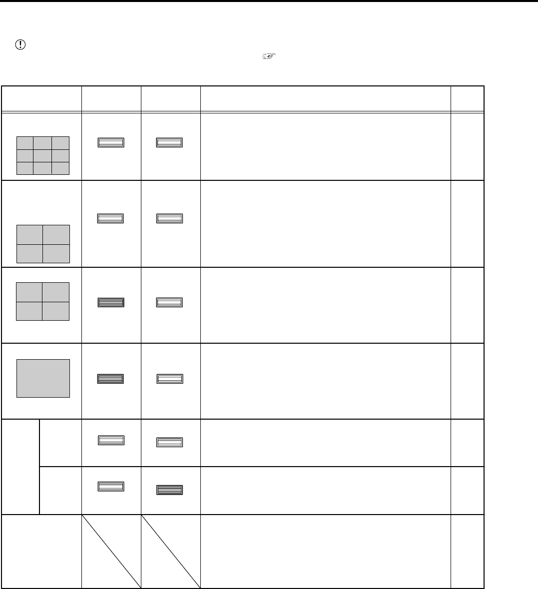
36
••••••••••••••••••••••••••••••••••••••••••••••••••••••••••••••••••••••••••••••••••••••••••••••••••••••••••••••••••••••••••••••••••••••••••••
<MPX DISPLAY SETTINGS> (continued)
OFF
ZOOM
OFF
ZOOM
OFF
ZOOM
OFF
ZOOM
OFF
ZOOM
ZOOM
OFF
SPLIT/
SEQUENCE
OFF
SPLIT/
SEQUENCE
OFF
SPLIT/
SEQUENCE
OFF
SPLIT/
SEQUENCE
SPLIT/
SEQUENCE
SPLIT/
SEQUENCE
Illuminating/Off of Camera number buttons
SPLIT/
SEQUENCE
button
Display ZOOM
button Page
37,38
37
38
38
35
35
-
Camera number button which has display is
illuminating.
Camera number buttons which has been activated as
100%, 200% or 400% will be illuminated.
Not available the magnification function when the
OUTPUT B indicator illuminates.
Iluminating
SPLIT4 (a)
SPLIT4 (b)
SPLIT4 (c)
Single screen Seqential
Single
screen
SPLIT4 Sequential
During Alarm recor-
ding and Motion
detection recording
Not
enlarged
Enlarged
*If the Alarm signal is
input during
SPLIT/ SEQUENCE
mode.
Regardless of SPLIT9, SPLIT4 or Single screen,
camera number buttons which are activated via
the Alarm recording start flashing.
The video of camera number selected in <OUTPUT A>
(<OUTPUT B>) } <SPLIT9 SCREEN SETTING> screen
is displayed using SPLIT9 display.
During video display, the corresponding camera number
button lights.
The video of camera number selected in <OUTPUT A>
(<OUTPUT B>) } <SPLIT4 SCREEN SETTING> screen
is displayed using SPLIT4 display.
During video display, the corresponding camera number
button lights.
The single screen video set in <OUTPUT A>
(<OUTPUT B>) } <SEQUENCE SETTING> screen is
displayed and updated in order by the set switching time.
During video display, the corresponding camera number
button lights.
The SPLIT4 screen video set in <OUTPUT A>
(<OUTPUT B>) } <SEQUENCE SETTING> screen is
displayed and updated in order by the set switching time.
During video display, the corresponding camera number
button lights.
Iluminating
Iluminating
SPLIT9
SPLIT4 sequential screen
can be switched.
Single screen sequential
can be switched.
■ The function of the SPLIT/SEQUENCE button, ZOOM button, and camera number buttons
The screen of cameras with no video input signal will appear blue. Furthermore, the screen of cameras set to
“OFF” for COVERT CAMERA SETTING will appear black ( see page 76).

37
•••••••••••••••••••••••••••••••••••••••••••••••••••••••••••••••••••••••••••••••••••••••••••••••••••••••••••••••••••••••••••• Operations
ENGLISH
■ MPX DISPLAY SETTINGS
With this unit, the multiplexer settings for the <OUTPUT
A> screen for the monitor video connected to the OUTPUT
A terminal and the analog output terminal and the
multiplexer settings for the <OUTPUT B> screen for live-
only monitor video connected to the OUTPUT B terminal
can be set individually.
<MPX DISPLAY SETTINGS>
>>
OUTPUT A
OUTPUT B ON/OFF OFF
OUTPUT B
<OUTPUT A>
>>
SPLIT4 SCREEN SETTING
SPLIT9 SCREEN SETTING
SEQUENCE SETTING
INTERLACE ON
<OUTPUT B>
>>
SPLIT4 SCREEN SETTING
SPLIT9 SCREEN SETTING
SEQUENCE SETTING
INTERLACE ON
SAME AS OUTPUT A
Select “ON” in the “OUTPUT B ON/OFF” to dis-
play the live monitor video of OUTPUT B on the
screen. When the setting is kept “OFF” in the “OUT-
PUT B ON/OFF”, the live monitor video of OUTPUT
B is not displayed.
When set the multiplexer setting of the <OUT-
PUT B> screen the same as the setting of the <OUT-
PUT A> screen, turn the JOG dial to move the cur-
sor to “SAME AS OUTPUT A” on the <OUTPUT B>
screen and turn the SHUTTLE ring clockwise.
When the ZOOM button is kept pressed for at
least 1 sec, the operation of the camera No. button
and the SPLIT/SEQUENCE button is switched to
the operation for OUTPUT A (monitor video
connected to the OUTPUT A terminal and the analog
output terminal) and OUTPUT B (monitor video
connected to the OUTPUT B terminal).
■ SPLIT4 SCREEN SETTING
For the SPLIT4 SCREEN SETTING, 3 types of SPLIT4
screen types (a, b and c) can be set.
1. Press the SET UP button
}
<SETTINGS>
}
Select
“OUTPUT A” (“OUTPUT B”) in the <MPX DISPLAY
SETTINGS> screen and turn the SHUTTLE ring clockwise.
• The <OUTPUT A> (<OUTPUT B>) screen appears.
2. Turn the JOG dial to select “SPLIT4 SCREEN SETTING”
and turn the SHUTTLE ring clockwise.
• The <SPLIT4 SCREEN SETTING> screen appears.
9
1
23
7
4
56
12
3
8
<SPLIT4 SCREEN SETTING>
>>
SPLIT4(a) SPLIT4(b)
( ) ( ) ( ) ( )
( ) ( ) ( ) ( )
SPLIT4(c)
( ) ( )
( ) ( )
3. Turn the JOG dial to select the split display to set (a, b or c)
and turn the SHUTTLE ring clockwise.
• The (most upper left) camera number reverses in color.
4. Turn the JOG dial to move to the camera number with the
reversed display and turn the SHUTTLE ring clockwise.
• The background of the camera number turns red and
flashes.
5. Turn the JOG dial to display the camera number to set and
turn the SHUTTLE ring clockwise.
• Flashing stops.
The same camera number can be set multiple
times on the split screen display. When multiple set-
tings with the same camera number have been
made, the playback image is displayed at the cam-
era location with the lowest number.
6. Repeat steps 4 and 5 to set the desired camera number.
7. When completed with setting, turn the SHUTTLE ring
counterclockwise.
• Setting is confirmed and the cursor appears.
8. To set other split screen displays, repeat steps 3 ~ 7.
9. When completed with all settings, turn the SHUTTLE ring
counterclockwise or press the SET UP button.
The <SPLIT4 SCREEN SETTING> screen can-
not be exited when camera number is flashing.
■ SPLIT9 SCREEN SETTING
For the SPLIT9 SCREEN SETTING, SPLIT9 screen can
be set.
1. Press the SET UP button
}
<SETTINGS>
}
Select
“OUTPUT A” (“OUTPUT B”) in the <MPX DISPLAY
SETTINGS> screen and turn the SHUTTLE ring clockwise.
• The <OUTPUT A> (<OUTPUT B>) screen appears.
2. Turn the JOG dial to select “SPLIT9 SCREEN SETTING”
and turn the SHUTTLE ring clockwise.
• The <SPLIT9 SCREEN SETTING> screen appears.
9
7
456
123
8
<SPLIT9 SCREEN SETTING>
>>
SPLIT9
( ) ( ) ( )
( ) ( ) ( )
( ) ( ) ( )
3. Turn the SHUTTLE ring clockwise.
• The (most upper left) camera number reverses in color.
4. Turn the JOG dial to move to the camera number with the
reversed display and turn the SHUTTLE ring clockwise.
• The background of the camera number turns red and
flashes.
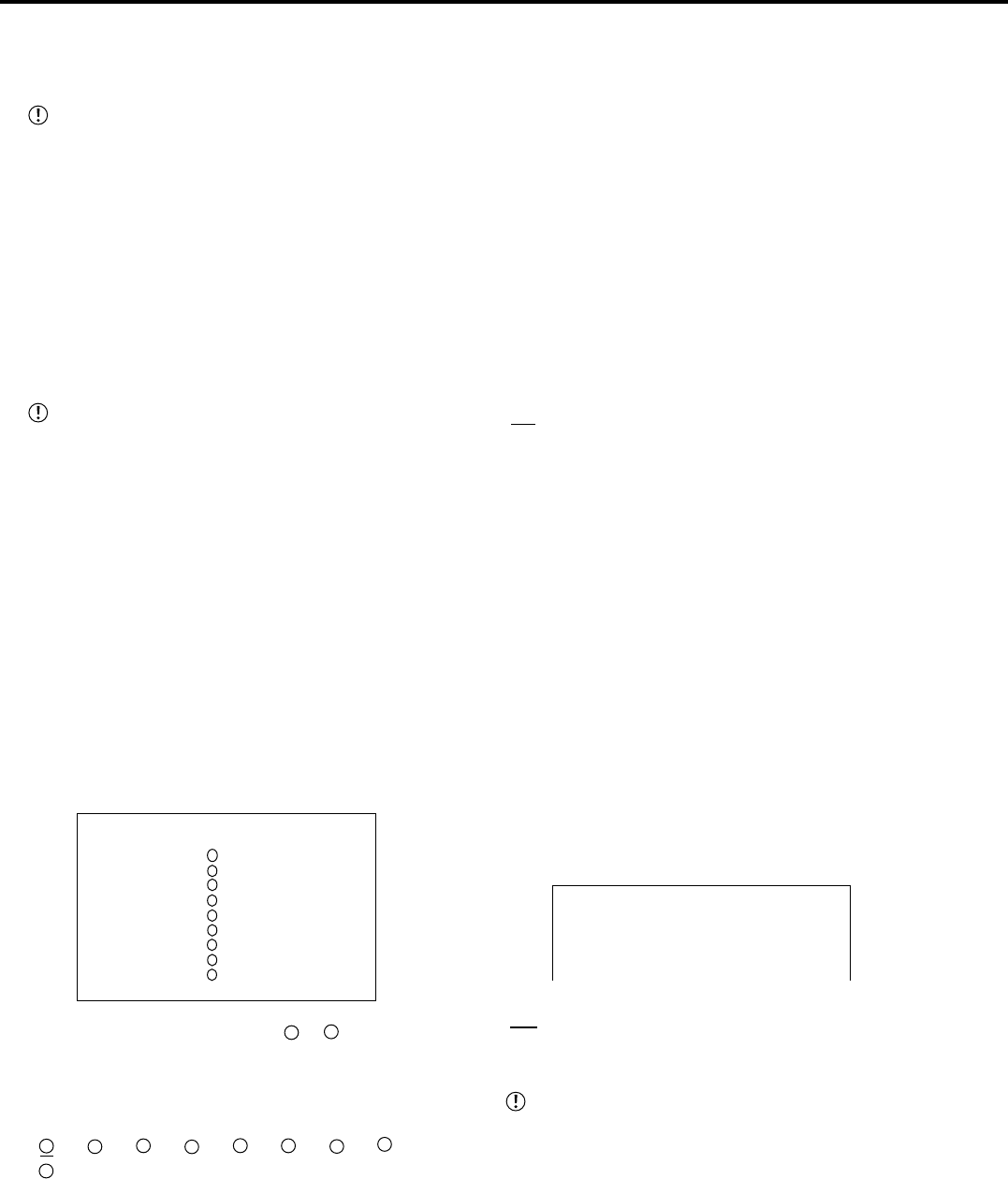
38
••••••••••••••••••••••••••••••••••••••••••••••••••••••••••••••••••••••••••••••••••••••••••••••••••••••••••••••••••••••••••••••••••••••••••••
<MPX DISPLAY SETTINGS> (continued)
5. Turn the JOG dial to display the camera number to set and
turn the SHUTTLE ring clockwise.
• Flashing stops.
The same camera number can be set multiple
times on the split screen display. When multiple set-
tings with the same camera number have been
made, the playback image is displayed at the cam-
era location with the lowest number.
6. Repeat steps 4 and 5 to set the desired camera number.
7. When completed with setting, turn the SHUTTLE ring
counterclockwise.
• Setting is confirmed and the cursor appears.
9. Turn the SHUTTLE ring counterclockwise or press the SET
UP button.
The <SPLIT9 SCREEN SETTING> screen can-
not be exited when camera number is flashing.
■ SEQUENCE SETTING
The display order of connected camera video can be
switched automatically or the switching time can be set.
Furthermore, the 3 types of split screen displays set in
“SPLIT4 SCREEN SETTING”, “SPLIT9 SCREEN
SETTING” can be switched automatically or the same cam-
era can be displayed repeatedly.
1. Press the SET UP button
}
<SETTINGS>
}
Select
“OUTPUT A” (“OUTPUT B) in the <MPX DISPLAY SETTINGS>
screen and turn the SHUTTLE ring clockwise.
• The <OUTPUT A> (<OUTPUT B>) screen appears.
2. Turn the JOG dial to select
}
“SEQUENCE SETTING” and
turn the SHUTTLE ring clockwise.
• The <SEQUENCE SETTING> screen appears.
<SEQUENCE SETTING>
9
7
4
5
6
1
2
3
8
<SEQUENCE SETTING>
SEQUENCE NUMBER TIME
>>
1 2S
2 2S
3 2S
4 2S
5 2S
6 2S
7 2S
8 2S
9 2S
SPLIT4 abc 2S
3. Select the desired display order (
1
~
9
) and turn the
SHUTTLE ring clockwise twice.
• The camera number display reverses in color when the
SHUTTLE ring is turned the first time. When the ring is turned
for the second time, the background turns red and flashes.
• Setting
“ 1 ”, “
2
”, “
3
”, “
4
”, “
5
”, “
6
”, “
7
”, “
8
”,
“
9
”, “ - ”
“ - ” : No display.
4. Display the desired camera number to display and turn the
SHUTTLE ring clockwise.
• The setting is confirmed.
5. Turn the JOG dial clockwise to shift the reversed display to
“TIME” and turn the SHUTTLE ring clockwise.
• The background of the “TIME” setting turns red and flashes.
6. Display the desired time and turn the SHUTTLE ring
clockwise.
• The setting is confirmed and flashing stops.
• The time can be set at 1 second intervals (max. 30 seconds).
7. Turn the SHUTTLE ring counterclockwise.
• The cursor appears to sequence number on the left.
8. Repeat steps 3 ~ 7 to set other display orders of camera
number and time.
9. (When setting switching for SPLIT4 sequential display • • • )
Select “SPLIT4” and turn the SHUTTLE ring clockwise twice.
• The setting reverses in color when the SHUTTLE ring is
turned the first time. When the ring is turned for the second
time, the background turns red and flashes.
10. Display the desired item to set and turn the SHUTTLE
ring clockwise.
• The setting is confirmed.
• Setting of “SPLIT4” ( default : SPLIT4 “abc” )
“abc” : SPLIT4(a), (b) and (c) are displayed using sequence
display.
“ab” : SPLIT4(a) and (b) are displayed using sequence
display.
“a” : SPLIT4(a) is displayed using sequence display.
11. Turn the JOG dial clockwise to shift the reversed display
to “TIME” and turn the SHUTTLE ring clockwise.
• The background of the “TIME” setting turns red and flashes.
12. Display the desired time and turn the SHUTTLE ring
clockwise.
• The setting is confirmed and flashing stops.
13. Turn the SHUTTLE ring counterclockwise.
• The cursor appears to “SPLIT4” on the left.
14. When completed with all settings, turn the SHUTTLE ring
counterclockwise or press the SET UP button.
■ INTERLACE
The picture quality when splitting the screen of
camera video can be set.
<OUTPUT A>
SPLIT4 SCREEN SETTING
SPLIT9 SCREEN SETTING
SEQUENCE SETTING
>>
INTERLACE ON
Setting ( default : “ON” )
“ON” : Video is displayed in detail.
“OFF” : Screen flickering is reduced.
Although screen flickering of video during SPLIT4
and SPLIT9 screen display can be reduced when
setting “INTERLACE” to “OFF”, the vertical resolu-
tion will drop.
1. Press the SET UP button
}
<SETTINGS>
}
Select
“OUTPUT A”(“OUTPUT B”) in the <MPX DISPLAY
SETTINGS> screen and turn the SHUTTLE ring clockwise.
• The <OUTPUT A> (<OUTPUT B>) screen appears.
2. Turn the JOG dial to select “INTERLACE” and display the
desired setting and confirm.
3. Turn the SHUTTLE ring counterclockwise or press the SET
UP button.
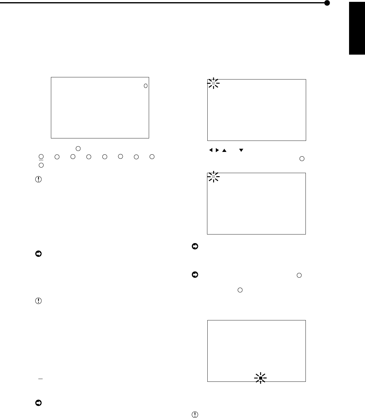
39
•••••••••••••••••••••••••••••••••••••••••••••••••••••••••••••••••••••••••••••••••••••••••••••••••••••••••••••••••••••••••••• Operations
ENGLISH
<MOTION DETECTION SETTINGS>
• Display “ • ” for the left half of the screen to inactivate
motion detection.
1. In “SELECTION CAMERA NUMBER , select the camera
for setting the detection area.
2. Select “DETECTION MASK SETTING” and turn the
SHUTTLE ring clockwise.
• The dotted screen with detection areas is displayed and the
background of the most upper left dot turns red and flashes.
& & &&&&&&&&&& &&&&
& & &&&&&&&&&& &&&&
& & &&&&&&&&&& &&&&
& & &&&&&&&&&& &&&&
& & &&&&&&&&&& &&&&
& & &&&&&&&&&& &&&&
& & &&&&&&&&&& &&&&
& & &&&&&&&&&& &&&&
& & &&&&&&&&&& &&&&
& & &&&&&&&&&& &&&&
& & &&&&&&&&&& &&&&
& & &&&&&&&&&& &&&&
3. Use the
, , and
buttons to select the dot to activate/
inactivate and press the camera number button
8
.
• The “ &&
&&
& ” (active) setting changes to “ • ” (inactive) setting.
• & &&&&&&&&&& &&&&
& & &&&&&&&&&& &&&&
& & &&&&&&&&&& &&&&
& & &&&&&&&&&& &&&&
& & &&&&&&&&&& &&&&
& & &&&&&&&&&& &&&&
& & &&&&&&&&&& &&&&
& & &&&&&&&&&& &&&&
& & &&&&&&&&&& &&&&
& & &&&&&&&&&& &&&&
& & &&&&&&&&&& &&&&
& & &&&&&&&&&& &&&&
When pressing the SPLIT/SEQUENCE button,
all dots change to “ & ” (active). When pressing the
ZOOM button, all dots change to “ • ” (inactive).
When pressing the camera number
8
button,
dot change to “ • ” (inactive). When pressing the
camera number
9
button, dot change to “ & ”
(active).
4. Repeat step 3 to activate/inactivate all desired dots.
• • ••••••&&&& &&&&
• • ••••••&&&& &&&&
• • ••••••&&&& &&&&
• • ••••••&&&& &&&&
• • ••••••&&&& &&&&
• • ••••••&&&& &&&&
• • ••••••&&&& &&&&
• • ••••••&&&& &&&&
• • ••••••&&&& &&&&
• • ••••••&&&& &&&&
• • ••••••&&&& &&&&
• • ••••••&&&& &&&&
5. Turn the SHUTTLE ring counterclockwise.
• The setting is confirmed and the display returns to the
<MOTION DETECTION SETTINGS> screen.
During set detection mask setting, other settings
are not accepted. To exit the menu screen during
setting, turn the SHUTTLE ring counterclockwise.
In this menu, the conditions of the motion detection func-
tion for normal recording and alarm recording, which is
started when detecting motion within the video of the con-
nected camera, are set.
■ SELECTION CAMERA NUMBER
The camera for motion detection setting is selected. Since
settings can be made for each camera, more detailed set-
tings are possible.
1
<MOTION DETECTION SETTINGS>
>>
SELECTION CAMERA NUMBER
DETECTION MASK SETTING
SENSITIVITY HIGH••<<<LOW
MOTION THRESHOLD 5
TEST MODE
Setting ( default : “
1
” )
“ 1 ”, “
2
”, “
3
”, “
4
”, “
5
”, “
6
”, “
7
”, “
8
”,
“
9
”
When selecting the <MOTION DETECTION
SETTINGS> screen during single screen display of
any specified camera number, that camera will be
displayed as the initial value of “SELECTION CAM-
ERA NUMBER”.
1. Press the SET UP button
}
<SETTINGS>
}
Select
“SELECTION CAMERA NUMBER” in the <MOTION
DETECTION SETTINGS> screen. Display the desired setting
and confirm.
Confirm the “SELECTION CAMERA NUMBER”
setting to switch the background to the video of the
selected camera number.
2. Turn the SHUTTLE ring counterclockwise or press the SET
UP button.
The motion detection function will not operate
when the <MOTION DETECTION SETTINGS>
screen is displayed.
■ DETECTION MASK SETTING
The area to activate motion detection is set here. Any of
the 192 dotted detection areas displayed by splitting indi-
vidually loaded video to equal 16 X 12 pixel sizes can be
selected and set.
Definition of setting mark ( default : all areas “ & ” (active) )
“ & ” : Area activated with motion detection.
“ • ” : Area inactivated with motion detection.
It is possible to set various areas per camera.
Example of screen setting
For the video loaded from the camera set in “SELECTION
CAMERA NUMBER” :
• Display “ & ” for the right half of the screen to activate
motion detection.

40
••••••••••••••••••••••••••••••••••••••••••••••••••••••••••••••••••••••••••••••••••••••••••••••••••••••••••••••••••••••••••••••••••••••••••••
Cautionary items concerning motion detection
• If changes are detected repeatedly, alarm recording
is also started repeatedly. Thus functions such as set-
ting change, etc., will not be accepted. In this case,
press the ALARM INTERRUPT button to forcibly stop
the motion detection function for a period of 5 minutes.
During, this time, settings can be changed. This manual
stop is automatically restored after 5 minutes and the
history of the manual stop is left in the history of the
WARNING LOG LIST. To cancel the alarm interrupt,
press the ALARM INTERRUPT button again.
• Even if the motion detection setting is active ALARM
IN terminal on the rear is constantly given priority over
the others.
• The M-DET indicator lights when the motion detection
function is in operation.
• When the SENSITIVITY is set too high, sometimes it
can cause the incorrect detection. Please watch out for
erroneous operation in case of connection to a system
with signaling using the motion detection of this unit.
• To perform alarm recording with the motion detection
function, set “TRIGGER” in the <ALARM SETTING>
screen to MD, MD/EXT or MD&EXT, set the “MOTION
DET REC” in the <RECORD SETTING> screen to
“ALARM” and set the recording intervals of “A-PPS” of
desired camera for alarm recording in the <RECORD
SETTING> screen.
• Motion detection will not operate while making set-
tings in the <MOTION DETECTION SETTINGS>.
<MOTION DETECTION SETTINGS> (continued)
■ SENSITIVITY
The sensitivity of detection for changes in the loaded video
data is set. The sensitivity setting is divided into the 5 lev-
els of brightness.
1
<MOTION DETECTION SETTINGS>
SELECTION CAMERA NUMBER
DETECTION MASK SETTING
>>
SENSITIVITY HIGH••<<<LOW
MOTION THRESHOLD 5
TEST MODE
Setting ( default : “HIGH • • < < < LOW” )
“HIGH • • • • < LOW”, “HIGH • • • < < LOW”,
“HIGH • • < < < LOW”, “HIGH • < < < < LOW”,
“HIGH < < < < < LOW”
Sensitivity increases as “<” increases from
“HIGH • • • • < LOW” to “HIGH < < < < < LOW”.
To detect the slightest changes, set to
“HIGH < < < < < LOW”. However, detection may
not operate properly due to flickering of fluorescent
lighting, etc.
1. Select the camera to set the sensitivity in “SELECTION
CAMERA NUMBER” ( see page 39).
2. Display the desired setting in “SENSITIVITY” and turn the
SHUTTLE ring clockwise.
• The setting is confirmed.
■ MOTION THRESHOLD
The minimum number of dots for starting the motion de-
tection operation from the number of active dots within the
detection area is set here. Motion detection operates when
change that exceeds the number of minimum dot set is
detected.
1
<MOTION DETECTION SETTINGS>
SELECTION CAMERA NUMBER
DETECTION MASK SETTING
SENSITIVITY HIGH••<<<LOW
>>
MOTION THRESHOLD 5
TEST MODE
Setting ( default : “5” )
“ 1 ” , “ 2 ”, • • ,“ 5 ”, • • • ,“191”, “192”
For MOTION THRESHOLD, set the number of
active dots in the detection area as the upper limit.
The motion detection function will not operate when
setting a value that exceeds this number.
1. Select the camera to set the motion threshold in
“SELECTION CAMERA NUMBER” ( see page 39).
2. Display the desired setting in “MOTION THRESHOLD” and
turn the SHUTTLE ring clockwise.
• The setting is confirmed.
■ TEST MODE
The set motion detection operation is tested here.
• • •••••••••• ••••
• • •••••••••• ••••
• • •••••••••• ••••
• • •••••••••• ••••
• • •••••••••• ••••
• • •••••••••• ••••
• • •••••••••• ••••
• • •••••••••• ••••
• • •••••••••• ••••
• • •••••••••• ••••
• • •••••••••• ••••
• • •••••••••• ••••
1. In “SELECTION CAMERA NUMBER” ( see page 39),
select the camera to test operates.
2. Select “TEST MODE” and turn the SHUTTLE ring
clockwise.
• The operation test begins.
3. To end “TEST MODE”, turn the SHUTTLE ring counter-
clockwise.
• During test operation, active areas of motion detection are
displayed using “ • ”. The screen displays “ &&
&&
& ” when motion
that meets the each condition of sensitivity and number of
dots for recording start is detected. If the motion detection
does not operate properly, set the conditions again.
• The red “ &&
&&
& ” display may be overdue to an actual motion.
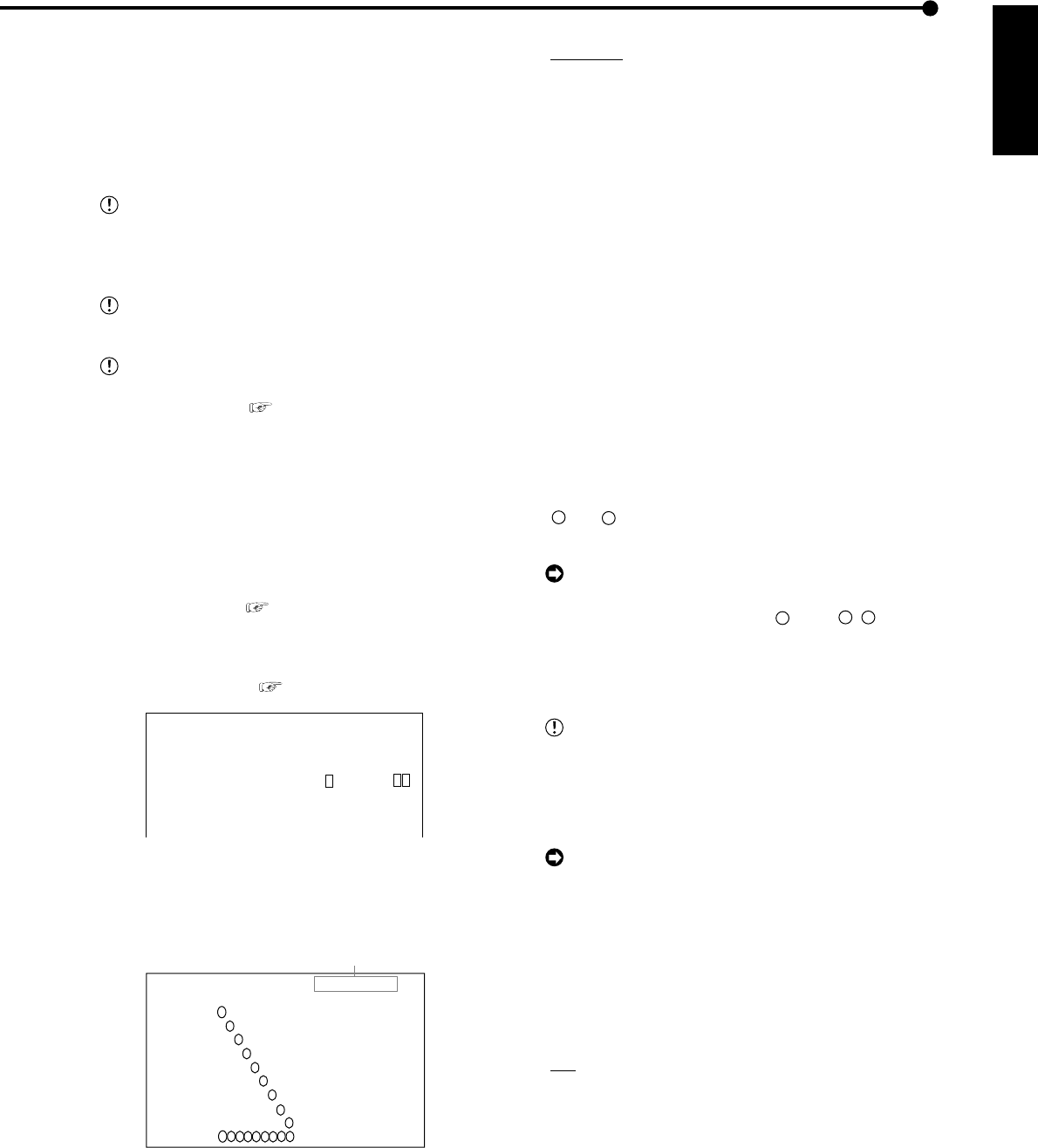
41
•••••••••••••••••••••••••••••••••••••••••••••••••••••••••••••••••••••••••••••••••••••••••••••••••••••••••••••••••••••••••••• Operations
ENGLISH
<RECORD SETTINGS>
■ Settings concerning normal recording and
alarm recording
This unit allows independent settings for normal recording
and alarm recording. By this, more detailed settings are
possible such as changing the recording intervals of the
camera inputting the alarm signals while maintaining the
normal recording settings as they are.
Certain settings and mode changes are limited
during Alarm recording. Pressing the ALARM INTER-
RUPT button halts additional alarm inputs, and lifts
the limitations by stopping recording.
During recording, the setting in the <RECORD
SETTING> screen cannot be changed.
When the cameras for recording are not input
video signal, warning display of “NO SIGNAL” ap-
pears (for details, see “Warnings and CALL
OUT output” pages 87,88).
■ Recording mode settings for normal
recording and alarm recording
Setting of the camera number for alarm recording and
emergency recording, the TRIGGER for alarm recording,
the recording intervals and recording picture quality for nor-
mal recording and alarm recording and whether to perform
pre-alarm recording for alarm recording can be set here
(for normal recording, see “Basic manual recording”
pages 21-23). Pre-alarm recording is a function to start re-
cording before the ALARM IN terminal on the rear of the
unit is grounded or motion is detected (for details concern-
ing pre-alarm recording, see page 64).
<RECORD SETTINGS>
>>
ALARM SETTING
RECORD SETTING
ALARM REC DURATION 5S
PRE ALARM REC ( S ) S
MOTION DET REC ALARM
1. Press the SET UP button
}
<SETTINGS>
}
Select “ALARM
SETTING” in the <RECORD SETTINGS> screen and turn the
SHUTTLE ring clockwise.
• The <ALARM SETTING> screen appears.
<ALARM SETTING>
>>
ALARM CH
ALARM RECORD CAMERA TRIGGER
1 -------- EXT
2 - ------- EXT
3 -- ------ EXT
4 --- ----- EXT
5 ---- ---- EXT
6 ----- --- EXT
7 ------ -- EXT
8 ------- - EXT
9 -------- EXT
EMR
9
7
456
123
8
9
7
456
123
8
<ALARM SETTING>
Camera selection during alarm recording
2. (When setting the camera selection during alarm recording
• • • )
Turn the JOG dial and move the cursor to camera selection
item for alarm recording and turn the SHUTTLE ring clockwise.
• The background of setting turns red and flashes.
• Setting ( default : “ALARM CH” )
“ALARM CH” : Alarm recording is performed for only the
cameras set for alarm recording and inputted with alarm
signals. When there is input of alarm signals from multiple
cameras, alarm recording is performed for all cameras
containing alarm signals.
“ALARM PLUS” : Recording is performed in the frame speed
set in “A-PPS” for the camera inputted with alarm signals
during normal recording. All other cameras will be recording
in the normal frame intervals.
“ALARM25” : Recording is performed so that normal
recording and alarm recording each are up to max. 25 frames.
With playback of a recording where an alarm recording has
occurred during normal recording, there will be no recording
interval display.
3. Display the desired item to set and turn the SHUTTLE ring
clockwise.
• The setting is confirmed and flashing stops.
4. (When setting “RECORD CAMERA” (the alarm recording
camera) and “TRIGGER” • • • )
Turn the JOG dial to select the desired “ALARM” (alarm sensor
input number) and turn the SHUTTLE ring clockwise.
• The first item from the left side in the “RECORD CAMERA”
setting display reverses in color.
• The camera numbers are lined in order of the number from
“
1
” to “
9
”. Multiple camera numbers can be selected for
one alarm camera channel number.
When turn the JOG dial counterclockwise, the cam-
era number setting or the TRIGGER setting will re-
verses in color in order such as
1
, EXT,
9
,
8
• • • .
5. Turn the JOG dial to display the desired camera number
reversed in color and turn the SHUTTLE ring clockwise.
• The background of setting turns red and flashes.
While the setting is flashing, the setting screen can-
not be exited even when pressing the SET UP button.
6. Turn the JOG dial to display the desired setting and turn the
SHUTTLE ring clockwise.
• The setting is confirmed and flashing stops.
Two or more camera numbers can be chosen to
one sensor input.
7. Turn the JOG dial clockwise to display “TRIGGER” setting
reversed in color and turn the SHUTTLE ring clockwise.
• The background of setting turns red and flashes.
8. Turn the JOG dial to display the desired setting and turn the
SHUTTLE ring clockwise.
• The setting is confirmed and flashing stops.
• Setting of “TRIGGER” ( default : “EXT” )
“EXT” : Alarm recording can only be started when the ALARM
IN terminal is grounded.
“MD&EXT” : Alarm recording can be started when the ALARM
IN terminal is grounded and the motion is detected
simultaneously.
“MD/EXT” : When the ALARM IN terminal is grounded or
motion is detected alarm recording is started.
“MD” : Alarm recording can only be started when the motion
is detected.
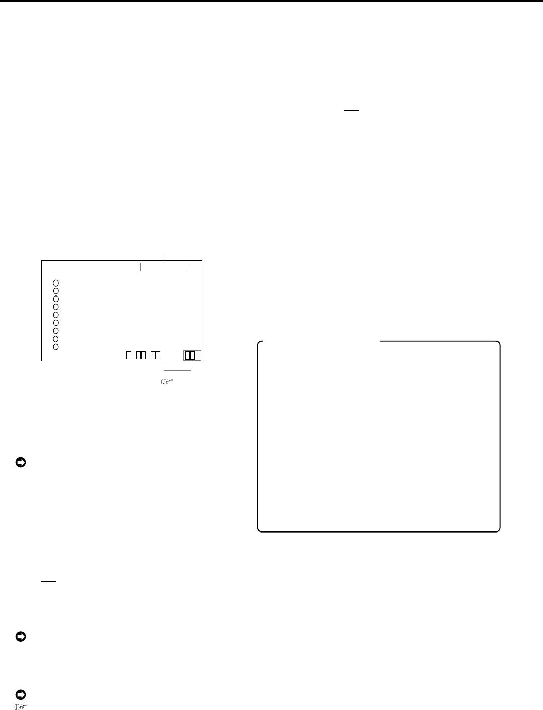
42
••••••••••••••••••••••••••••••••••••••••••••••••••••••••••••••••••••••••••••••••••••••••••••••••••••••••••••••••••••••••••••••••••••••••••••
<RECORD SETTINGS> (continued)
9. (When setting the emergency recording camera • • • )
Turn the JOG dial and move the cursor to “EMR” and turn the
SHUTTLE ring clockwise.
• The first item from the left side in the “ALARM RECORD
CAMERA” setting display reverses in color.
10. Repeat steps 5, 6 for settings.
11. When the setting is complete, turn the SHUTTLE ring
counterclockwise.
• The cursor moves to the camera number on the left.
• When continuing with other camera number settings, turn
the JOG dial to move the cursor to the desired camera number
and repeat steps 4 ~ 11 to perform the settings.
12. (When setting recording intervals and recording picture
quality • • • )
Press the SET UP button
}
<SETTINGS>
}
Select “RECORD
SETTING” in the <RECORD SETTINGS> screen and turn the
SHUTTLE ring clockwise.
• The <RECORD SETTING> screen appears.
<RECORD SETTING>
>>
ALARM CH
NO PPS GRADE A-PPS A-GRADE
2.5P STD 2.5P STD
2.5P STD 2.5P STD
2.5P STD 2.5P STD
2.5P STD 2.5P STD
2.5P STD 2.5P STD
2.5P STD 2.5P STD
2.5P STD 2.5P STD
2.5P STD 2.5P STD
2.5P STD 2.5P STD
<ESTD REC> D H M
<RECORD SETTING>
Camera selection during alarm recording
9
7
4
5
6
1
2
3
8
CAUTION : For <ESTD REC>,
see
“Continuous recording time table”, pages 83,84.
Appears when “PARTITION” is set.
About <ESTD REC>
• The estimated recordable time is displayed as <ESTD REC>
depending on the “PPS” and “GRADE” settings. (The time
will not change when changing the alarm recording settings.)
The storage area in MAIN HDD set in “PARTI-
TION” is displayed with the percentage (%) and the
recordable time of that storage area is displayed in
“<ESTD REC>”.
13. (When setting the recording intervals and recording picture
quality for normal recording
• • •
)
Turn the JOG dial to select the desired camera number and
turn the SHUTTLE ring clockwise twice.
• The background of the “PPS” display changes to red and flashes.
• Setting of “PPS” ( default : “2.5P” )
“5P”, “2.5P”, “1.667P”, “1.25P”, “1P”, “0.833P”, “0.625P”,
“0.5P”, “0.2P”, “0.1P”, “0.05P”, “0.025P”, “- - - - - -”
“- - - - - -” : Recording cannot be performed with camera set
to this item.
Pressing the WARNING RESET button while the
cursor is on the left of the desired camera number
changes that camera’s “PPS” and “A-PPS” to “- - -
- - -”.
For details concerning normal recording settings,
see “Setting the recording interval and recording
picture quality for normal recording” pages 22,23.
14. Display the desired item to set and turn the SHUTTLE
ring clockwise.
• The setting is confirmed and flashing stops.
15. Turn the JOG dial clockwise to reverse display the
“GRADE” setting and turn the SHUTTLE ring clockwise.
• The background of the “GRADE” display changes to red
and flashes.
• Setting of “GRADE” ( default : “STD” )
“SUPER”, “HIGH”, “STD”(STANDARD), “BASIC”, “LONG”
16. Display the desired item to set and turn the SHUTTLE
ring clockwise.
• The setting is confirmed and flashing stops.
17. (When setting recording intervals and recording picture
quality for alarm recording • • • )
Repeat steps 13 ~ 16 and select desired settings for “A-PPS”
and “A-GRADE” as well.
18. When the setting is complete, turn the SHUTTLE ring
counterclockwise.
• The cursor moves to the camera number directly to the left.
19. When continuing with other camera number, turn the JOG
dial to move the cursor to the desired camera number and
repeat steps 13 ~ 18 for settings.
20. When completed with all settings, turn the SHUTTLE ring
counterclockwise or press the SET UP button.
About alarm recording
• If alarm recording or emergency recording is entered
during timer recording, recording is stopped at the stop
time set for time recording.
• If “TRIGGER” for <ALARM SETTING> is set to “MD/
EXT”, the last alarm entered takes priority.
• If “TRIGGER” for <ALARM SETTING> is set to “MD/
EXT” and <ALARM REC DURATION> is set to
“MANUAL”, alarm recording will stop 2 seconds after
entering if MOTION DETECTION is entered afterwards
even if the ALARM IN terminal is grounded.
• If there is a power outage during alarm recording or
emergency recording, alarm recording and emergency
recording are released after power is restored.
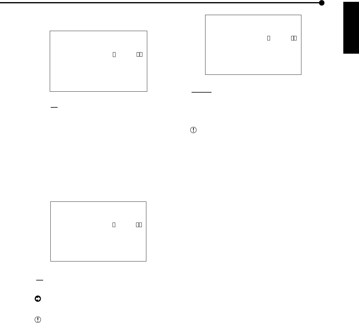
43
•••••••••••••••••••••••••••••••••••••••••••••••••••••••••••••••••••••••••••••••••••••••••••••••••••••••••••••••••••••••••••• Operations
ENGLISH
■ ALARM REC DURATION
The recording time during alarm recording can be set.
<RECORD SETTINGS>
ALARM SETTING
RECORD SETTING
>>
ALARM REC DURATION 5S
PRE ALARM REC ( S ) S
MOTION DET REC ALARM
Setting ( default : “5S” )
“2S”, “5S”, “10S”, “15S”, “30S”, “45S”, “1M”, “2M”,
“5M”, “10M”, “20M”, “30M”, “60M”, “MANUAL”
“MANUAL” : Alarm recording is continued until the
grounding of the ALARM IN terminals is cancelled.
1. Press the SET UP button
}
<SETTINGS>
}
Select “ALARM
REC DURATION” in the <RECORD SETTINGS> screen.
Display the desired setting and confirm.
2. Turn the SHUTTLE ring counterclockwise or press the SET
UP button.
■ PRE ALARM REC
The pre-alarm recording can be set.
<RECORD SETTINGS>
ALARM SETTING
RECORD SETTING
ALARM REC DURATION 5S
>>
PRE ALARM REC ( S ) S
MOTION DET REC ALARM
Setting ( default : “0S” )
“0S”, “1S”, “2S”, • • • • • ,“58S”, “59S”, “60S”, “90S”,
“120S”, “150S”, “180S”
When “0S” is selected, the pre-alarm recording
is inoperable.
The maximum pre-alarm recordable time is dis-
played in “( )”. Beware that when set the pre-alarm
recording time longer than the maximum the set-
tings will turn red. Set the time within the recording
time limit, so that the display returns to white. Even
if the time is set beyond the limit, Pre-Alarm record-
ing time is not changed.
1. Press the SET UP button
}
<SETTINGS>
}
Select “PRE
ALARM REC” in the <RECORD SETTINGS> screen, and
display the desired setting.
2. Turn the SHUTTLE ring counterclockwise or press the SET
UP button.
■ MOTION DET REC
Select whether alarm recording or normal recording is to
be started when motion is detected.
<RECORD SETTINGS>
ALARM SETTING
RECORD SETTING
ALARM REC DURATION 5S
PRE ALARM REC ( S ) S
>>
MOTION DET REC ALARM
Setting ( default : “ALARM” )
“ALARM” : Alarm recording is started when the mo-
tion is detected.
“NORMAL” : Normal recording is started when the
motion is detected.
When “NORMAL” is selected by “MOTION DET
REC” setting during alarm partition employment,
data is recorded on HDD(MAIN). When playing back
recorded data, please select “MAIN” in the
“PLAYBACK DEVICE” setting.
1. Press the SET UP button
}
<SETTINGS>
}
Select
“MOTION DET REC” in the <RECORD SETTINGS> screen,
and display the desired setting.
2. Turn the SHUTTLE ring counterclockwise or press the SET
UP button.
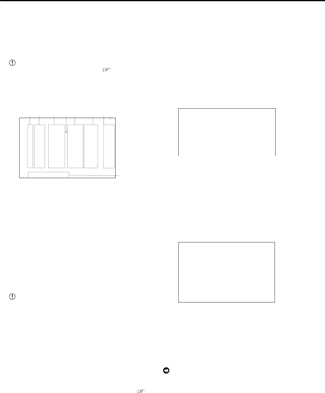
44
•••••••••••••••••••••••••••••••••••••••••••••••••••••••••••••••••••••••••••••••••••••••••••••••••••••••••••••••••••••••••••••••••••••••••••
•
■ TIMER PROGRAM SETTINGS
Up to 3 most used operation patterns can be set in ad-
vance. By individually setting the camera, recording inter-
vals and recording picture quality for normal recording/
alarm recording to A ~ D, settings can be changed in-
stantly by switching operations and is very convenient.
Before recording, accurately set the date and cur-
rent time (for setting the date and time, see pages
20,21).
■ TIMER PROGRAM
♦ Structure of the <TIMER PROGRAM> screen
1) 2) 3) 4) 5) 6) 7) 8)
9)
<TIMER PROGRAM> P1
DW START END MODE MD
>>
1 --- --:-- --:-- ---- -
2 --- --:-- --:-- ---- -
3 --- --:-- --:-- ---- -
4 --- --:-- --:-- ---- -
5 --- --:-- --:-- ---- -
6 --- --:-- --:-- ---- -
7 --- --:-- --:-- ---- -
8 --- --:-- --:-- ---- -
SPL SAT-SUN
1) PROGRAM NUMBER
Up to 8 programs can be set for a single operation.
2) DW
The day of week from “SUN” to “SAT” can be set.
“DAY” : When recording at the same time daily.
“SPL” : When recording the period specified in “9) SPL
(special day of the week setting)” below.
“HOL” : When setting holidays specified in the <HOLI-
DAY SETTING> screen.
3) REC START TIME
The time is indicated using the 24-hour system.
If there is an overlap in the reservation time, the
program with the larger program number is given pri-
ority for recording.
4) NEXT DAY
Next day mark appears when recording is to be carried
over to the following day.
5) REC END TIME
6) MODE
“A” ~ “D” : When recording using the camera operation
type and recording intervals set in “REC MODE A” ~
“REC MODE D” of the <TIMER PROGRAM SETTINGS>
screen (for details concerning REC mode settings,
see pages 22,23).
“SKIP” : When temporarily skipping timer recording (the
recording will not be made for the specified time frame
of that program number).
7) MD
The motion detection function can be set to ON/OFF.
8) Select timer setting number (P1 ~ P3) is displayed.
9) SPL (special day of the week setting)
The start day of the week and end day of the week are
set. When selecting “SPL” in “DW”, the period from the
start day of the week and end day of the week set here
are active.
Example : Using program 1 in <TIMER PROGRAM>
P2, REC MODE A will record to Wednesday ~ Saturday
from 12:30 to 13:00 and “MD” is set to “ON”.
1. Press the SET UP button
}
<SETTINGS>
}
select “TIMER
PROGRAM SETTINGS”.
<TIMER PROGRAM SETTINGS>
>>
SELECTED PATTERN P1-SET
HOLIDAY SETTING
REC MODE A
REC MODE B
REC MODE C
REC MODE D
ALARM REC DURATION 5S
2. Check to see that the cursor is to the left of “SELECTED
PATTERN” and turn the SHUTTLE ring clockwise twice.
• The “P1” display reverses in color when the SHUTTLE ring
is turned the first time. When the ring is turned for the second
time, the background turns red and flashes.
3. Turn the JOG dial to select “P2” and turn the SHUTTLE ring
clockwise.
• The setting is confirmed and flashing stops.
4. Turn the JOG dial clockwise to reverse display “SET” and
turn the SHUTTLE ring clockwise.
• The <TIMER PROGRAM> screen appears.
<TIMER PROGRAM> P2
DW START END MODE MD
>>
1 --- --:-- --:-- ---- -
2 --- --:-- --:-- ---- -
3 --- --:-- --:-- ---- -
4 --- --:-- --:-- ---- -
5 --- --:-- --:-- ---- -
6 --- --:-- --:-- ---- -
7 --- --:-- --:-- ---- -
8 --- --:-- --:-- ---- -
SPL SAT-SUN
5. Check to see that the cursor is to the left of program number
“1” and turn the SHUTTLE ring clockwise twice.
• The “DW” display reverses in color when the SHUTTLE ring
is turned for the first time. When the ring is turned for the
second time, the background turns red and flashes.
6. Turn the JOG dial to display “SPL” in “DW” and turn the
SHUTTLE ring clockwise.
• The setting is confirmed and flashing stops.
When selecting the wrong day of the week in error,
turn the SHUTTLE ring clockwise, use the JOG dial to
display the correct day of the week and turn the SHUT-
TLE ring clockwise again.
7. Turn the JOG dial clockwise to move the reversed display
to the “hour” of the start time and turn the SHUTTLE ring
clockwise.
• The background of the “hour” of the START changes to red
and flashes.
<TIMER PROGRAM SETTINGS>
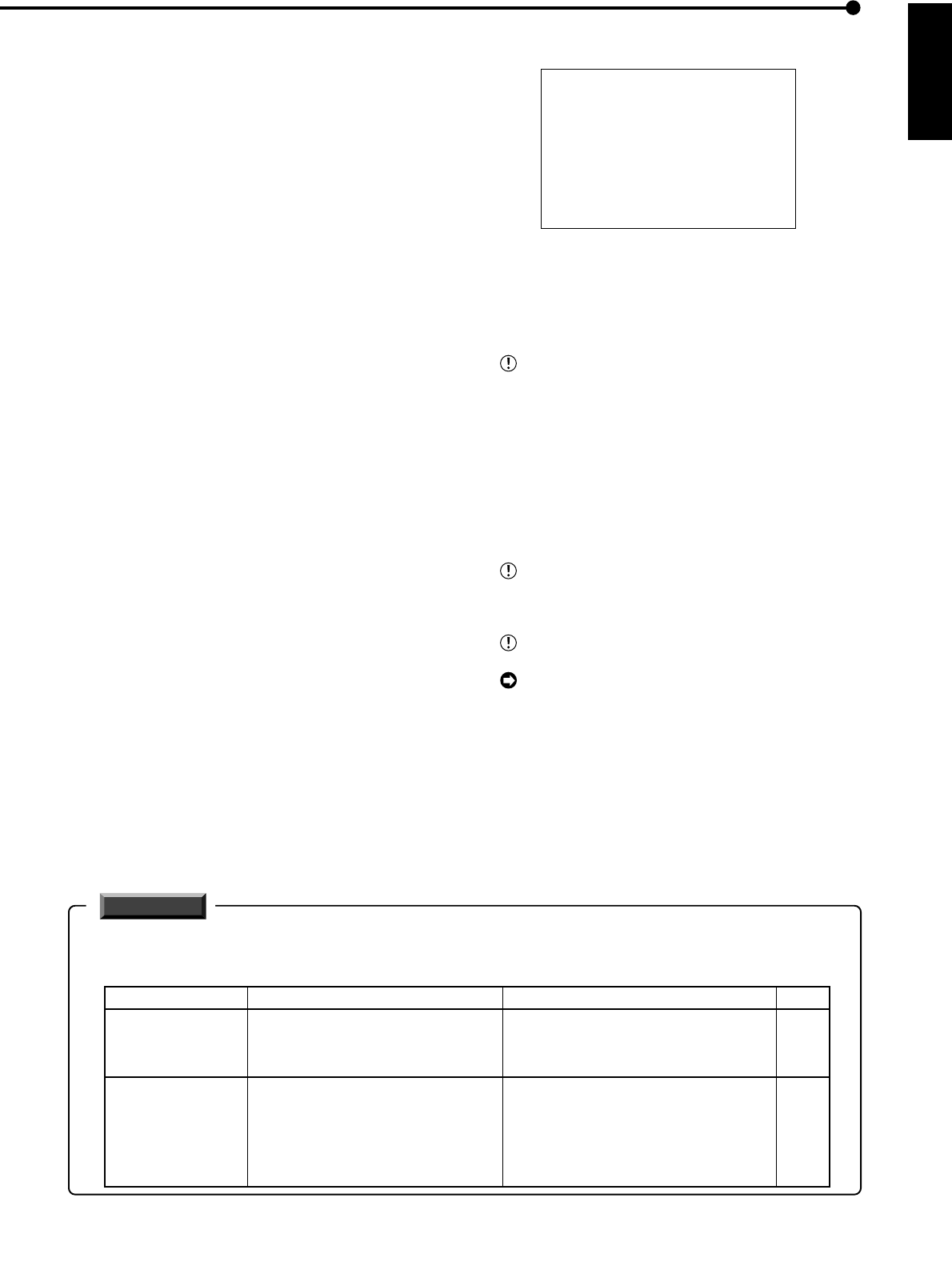
45
45
ENGLISH
•
•••••••••••••••••••••••••••••••••••••••••••••••••••••••••••••••••••••••••••••••••••••••••••••••••••••••••••••••••••••••••••• Operations
8. Turn the JOG dial to display “12 ” in the “hour” and turn the
SHUTTLE ring clockwise.
• The setting is confirmed and flashing stops.
9. Repeat steps 7 and 8 to set “30” in “minutes” of the start
time and “13” in the “hour” and “00” in the “minutes” of the
end time, and then confirm.
10. Turn the JOG dial clockwise to move the reversed display
to the “MODE” and turn the SHUTTLE ring clockwise.
• The background of the “MODE” setting turns red and flashes.
11. Turn the JOG dial to display “A” in “MODE” and turn the
SHUTTLE ring clockwise.
• The setting is confirmed and flashing stops.
12. Turn the JOG dial clockwise to move the reversed display
to the “MD” and turn the SHUTTLE ring clockwise.
• The background of the “MD” setting turns red and flashes.
13. Turn the JOG dial to display “ON” in “MD” and turn the
SHUTTLE ring clockwise.
• The setting is confirmed and flashing stops.
14. Turn the SHUTTLE ring counterclockwise.
• The cursor appears to the program number on the left.
15. When input timer reservations in other program number,
repeat steps 5 ~ 14.
16. Turn the JOG dial to select “SPL” and turn the SHUTTLE
ring clockwise twice.
• The start day display reverses in color when the SHUTTLE
ring is turned for the first time. When the ring is turned for
the second time, the background turns red and flashes.
17. Turn the JOG dial to display “WED” in start day and turn
the SHUTTLE ring clockwise.
• The setting is confirmed and flashing stops.
18. Turn the JOG dial clockwise to move the reversed display
to the end day and turn the SHUTTLE ring clockwise.
• The background of the end day setting turns red and flashes.
19. Turn the JOG dial to display “SAT” in end day and turn the
SHUTTLE ring clockwise.
• The setting is confirmed and flashing stops.
20. Turn the SHUTTLE ring counterclockwise.
• The cursor appears to the “SPL” on the left.
<TIMER PROGRAM> P2
DW START END MODE MD
1
SPL 12:30 13:00 A ON
2 --- --:-- --:-- ---- -
3 --- --:-- --:-- ---- -
4 --- --:-- --:-- ---- -
5 --- --:-- --:-- ---- -
6 --- --:-- --:-- ---- -
7 --- --:-- --:-- ---- -
8 --- --:-- --:-- ---- -
>>
SPL WED-SAT
21. Turn the SHUTTLE ring counterclockwise or press the SET
UP button.
• Turn the SHUTTLE ring counterclockwise to return the cursor
to the previous operation. Then, press the SET UP button to
clear the <TIMER PROGRAM SETTINGS> screen and return
to the normal screen.
If there is an unset item with in the program (- - -
display), the setting screen cannot be exited even when
turning the SHUTTLE ring counterclockwise. In this
case, set all unset items.
22. Press the TIMER button.
• The TIMER button lights.
• Timer recording starts if the current time is within the timer
reservation time frame.
• The power turns off and recording will be in the stand-by
mode if the current time is not within the timer reservation
time frame.
Timer recording/timer recording standby can be
cancelled by pressing the TIMER button again for more
than 1 second.
Not available during alarm recording.
To delete program contents, or to exit the program
without performing settings, press the WARNING RE-
SET button during program setting.
INFORMATION
Recording will not be performed if there is an error in the setting. To prevent such errors for timer record-
ing, this unit notifies errors using methods shown below. If there is an error in the setting, take the
necessary procedures shown below.
Unit status
TIMER button flashes.
Series of short beeps
(beep-beep-beep)
will sound.
Timer recording is not
performed even when
the timer recording
time is reached.
1) The date/time is not set.
2) Timer reservation setting has not been
set to operate.
3) Program is currently being set.
• “HDD REPEAT REC MAIN” is set to “OFF”
or “HDD REPEAT REC SUB”, is set to “OFF”.
There is no HDD space left of HDD(MAIN),
HDD(SUB).
Description of error Countermeasure Page
1) Set the date/time.
2) Set the correct reservation.
3) Check the settings.
• Press the WARNING RESET button for
canceling the warning.
• Set to “ON” in the “HDD REPEAT REC MAIN”
or “HDD REPEAT REC SUB” when “OFF” is
selected.
20,21
44,45
44,45
87
47
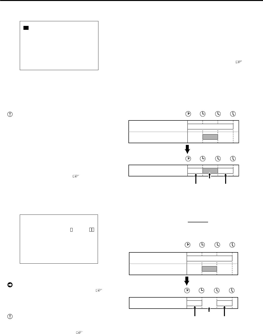
46
•••••••••••••••••••••••••••••••••••••••••••••••••••••••••••••••••••••••••••••••••••••••••••••••••••••••••••••••••••••••••••••••••••••••••••
•
■ HOLIDAY SETTING
Holidays throughout the year can be set in advance.
<HOLIDAY SETTING>
--/-- --/-- --/-- --/--
--/-- --/-- --/-- --/--
--/-- --/-- --/-- --/--
--/-- --/-- --/-- --/--
--/-- --/-- --/-- --/--
DAY/MONTH
1. Press the SET UP button
}
<SETTINGS>
}
Select
“HOLIDAY SETTING” in the <TIMER PROGRAM SETTINGS>
screen, and display the desired holidays and confirm.
2. Turn the SHUTTLE ring counterclockwise or press the SET
UP button.
When overlap both holidays set in the <HOLIDAY
SETTING> screen and the <TIMER PROGRAM>
screen, the unit records giving the priority to the holi-
day set in the <TIMER PROGRAM> screen over the
others.
■ Recording mode settings A ~ D for normal
recording/alarm recording
The camera, recording intervals and recording picture qual-
ity for normal recording/alarm recording can be set to 4
patterns of recording mode settings A ~ D (for details con-
cerning recording mode settings, see pages 22,23,
41-43).
1. Press the SET UP button
}
<SETTINGS>
}
Select “REC
MODE A” in the <TIMER PROGRAM SETTINGS> screen and
turn the SHUTTLE ring clockwise.
• The <REC MODE A> screen appears.
<REC MODE A>
>>
ALARM SETTING
RECORD SETTING
PRE ALARM REC ( S ) S
MOTION DET REC ALARM
2. Turn the JOG dial to select either “ALARM SETTING”,
“RECORD SETTING” or “PRE ALARM REC” and confirm.
For details on “ALARM SETTING”, “RECORD
SETTING” and “PRE ALARM REC” settings, see
pages 41-43.
3. When continuing to REC MODE B ~ D, repeat step 2.
The storage area in MAIN HDD set in “PARTITION”
is displayed with the percentage(%) and the record-
able time of that storage area is displayed in “<ESTD
REC>” (For details on PARTITION, see page 75).
■ MOTION DET REC
Recording is done with the recording interval and the
quality set by “A-PPS” and “A-GRADE”, independent of
whether “ALARM” or “NORMAL” has been selected (for
details concerning setting MOTION DET REC, see page
43).
■ ALARM REC DURATION
The recording time for alarm recording can be set (for
details concerning setting ALARM REC DURATION,
see page 43).
♦ Overlapping Timer settings
When Timer settings overlap, the unit will give priority to
the higher-numbered program.
Example 1
14:00 15:00 16:00 17:00
14:00 15:00 16:00 17:00
Example 1)
In Program 1, recording is set for PPS
to 5P, from 14:00 to 17:00.
1P
In Program 2, recording is set for PPS
to 1P, from 15:00 to 16:00.
Actual recorded contents 5P 5P
Program 2
5P
1P
Program 1 Program 1
Example 2
• Program 1 is set for 14:00 to 17:00 with the PPS to 5P.
• Program 2 is set for 15:00 to 16:00 with the SKIP setting.
Again, the unit will give priority to Program 2 for the duration of
the overlapping period. As shown in the illustration below, the
unit will activate the Skip setting from 15:00 to 16:00.
5P 5P
NO
RECORDING!
14:00 15:00 16:00 17:00
14:00 15:00 16:00 17:00
Example 2)
SKIP
In Program 2, the SKIP setting is
entered for 15:00 to 16:00.
5P
Actual recorded contents
Program 2
Program 1 Program 1
In Program 1, recording is set for PPS
to 5P, from 14:00 to 17:00.
<TIMER PROGRAM SETTINGS> (continued)

47
ENGLISH
•••••••••••••••••••••••••••••••••••••••••••••••••••••••••••••••••••••••••••••••••••••••••••••••••••••••••••••••••••••••••••• Operations
Setting ( default : “OFF” )
“ON” : After the recorded data is played back to the
end, playback is resumed by automatically returning to
the beginning of the recorded data.
“OFF” : After the recorded data is played back to the
end, playback is stopped.
1. Press the SET UP button
}
<SETTINGS>
}
<INITIAL SET
UP/INFORMATION>
}
Select “HDD REPEAT PLAY” in the
<HDD SETTINGS> screen. Display the desired setting and
confirm.
2. Turn the SHUTTLE ring counterclockwise or press the SET
UP button.
♦ IM-CHECK PLAY
This function is to check whether alterations have been
made to the recorded video or the recording date/time.
“IMAGE MODIFIED” warning is displayed when alteration
is checked.
<HDD SETTINGS>
HDD REPEAT REC MAIN ON
HDD REPEAT REC SUB OFF
HDD REPEAT PLAY OFF
>>
IM-CHECK PLAY OFF
SEQUENTIAL PLAY OFF
Setting ( default : “OFF” )
“ON” : Alteration check is performed during playback
and displays a warning at the point containing altera-
tion.
“OFF” : Alteration check is not performed.
This function may cause problems during recording
and playback. Normally, set this function to “OFF”.
1. Press the SET UP button
}
<SETTINGS>
}
<INITIAL SET
UP/INFORMATION>
}
Select “IM-CHECK PLAY” in the <HDD
SETTINGS> screen. Display the desired setting and confirm.
2. Turn the SHUTTLE ring counterclockwise or press the SET
UP button.
3. Select the device for alteration check and then start playback.
Warning will also be displayed for parts where re-
corded data is damaged for some reason.
IMAGE MODIFIED( )
12
3
When performing complex playback operations with
the SHUTTLE ring during alteration check, the “IMAGE
MODIFIED” warning may appear. Perform alteration
check using playback or playback with changed play-
back intervals.
■ HDD SETTINGS
♦ HDD REPEAT REC MAIN/HDD REPEAT REC
SUB
The operation when HDD (Hard Disk Drive) space be-
comes full during recording.
<HDD SETTINGS>
>>
HDD REPEAT REC MAIN ON
HDD REPEAT REC SUB OFF
HDD REPEAT PLAY OFF
IM-CHECK PLAY OFF
SEQUENTIAL PLAY OFF
“HDD REPEAT REC SUB” is appeared when
“PARTITION” is selected on “HDD SETTING” of the
<INITIALIZATION> screen.
Setting ( default of HDD REPEAT REC MAIN : “ON”, default
of HDD REPEAT REC SUB : “OFF”)
“ON” : Automatically returns to the beginning of the
HDD and resumes recording (by overwriting old data).
“STANDBY” : When the HDD space becomes empty,
recording is stopped and the unit switches to the
standby mode. Recording is resumed when the REC
terminal is grounded or the REC button is pressed.
Recording is temporarily stopped if the alarm input is
continuously grounded or during timer recording. Then,
recording is resumed from the beginning of the HDD.
“OFF” : Recording is stopped and “REC/FULL” or “REC/
SUB FULL” is displayed on the screen. To resume re-
cording, press the WARNING RESET button to cancel
the warning display and press the REC button.
If either the WARNING “REC/FULL” or “REC/SUB
FULL” appears when the ALARM PARTITION is set, re-
cording on both will stop.
“STANDBY” is displayed only in “HDD REPEAT
REC MAIN”.
1. Press the SET UP button
}
<SETTINGS>
}
<INITIAL SET
UP/INFORMATION>
}
Select “HDD REPEAT REC MAIN” or
“HDD REPEAT REC SUB” in the <HDD SETTINGS> screen.
Display the desired setting and confirm.
2. Turn the SHUTTLE ring counterclockwise or press the SET
UP button.
♦ HDD REPEAT PLAY
The contents recorded on the HDD (Hard Disk Drive)
can be repeatedly played back.
<HDD SETTINGS>
HDD REPEAT REC MAIN ON
HDD REPEAT REC SUB OFF
>>
HDD REPEAT PLAY OFF
IM-CHECK PLAY OFF
SEQUENTIAL PLAY OFF
<INITIAL SET UP/INFORMATION>
48
••••••••••••••••••••••••••••••••••••••••••••••••••••••••••••••••••••••••••••••••••••••••••••••••••••••••••••••••••••••••••••••••••••••••••••
♦ SEQUENTIAL PLAY
It is possible to make archive of the video recorded with
this unit to an analogue video recorder, etc., while playing
back the video of each camera in order using the single
screen display. During single screen sequential playback,
the SPLIT/SEQUENCE button will light. In addition, the
playback order/time of each camera will be the order of
the recorded video.
<HDD SETTINGS>
HDD REPEAT REC MAIN ON
HDD REPEAT REC SUB OFF
HDD REPEAT PLAY OFF
IM-CHECK PLAY OFF
>>
SEQUENTIAL PLAY OFF
Setting ( default : “OFF” )
“ON” : Plays back the video in the single screen se-
quential mode.
“OFF” : Does not play back the video in the single
screen sequential mode.
Playback is performed during camera sequential play
at an interval of 25P. To change the playback interval, press
the PLAY button (or the REV. PLAY button)( see
“Changing playback intervals, pages 65,66).
1. Press the SET UP button
}
<SETTINGS>
}
<INITIAL SET
UP/INFORMATION>
}
Select “SEQUENTIAL PLAY” in the
<HDD SETTINGS> screen. Display the desired setting and
confirm.
2. Turn the SHUTTLE ring counterclockwise or press the SET
UP button.
3. Press the PLAY button.
4. Press one of the camera number buttons with recorded video.
• Single screen sequential playback starts.
When performing camera sequential playback for
video with long recording intervals, the video of the
largest camera number selected for recording will be
played back the longest.
Only the camera number (title) of the pressed cam-
era number button is displayed. Other camera number
(titles) will not be displayed. If display is not necessary,
select “NONE” in the <CAMERA DISPLAY> ( see
page 32).
■ AUDIO RECORDING
This unit can simultaneously record audio along with the
video. When recording audio, the continuous recording
time becomes shorter than when recording only video.
<INITIAL SET UP/INFORMATION>
HDD SETTINGS
>>
AUDIO RECORDING OFF
REAR TERMINAL SETTINGS
COMMUNICATION PORT SETTINGS
INFORMATION/SERVICE
PASSWORD
LANGUAGE SELECTION
Setting ( default : “OFF” )
“ON” : Records video and audio.
“ALARM” : During alarm recording or emergency re-
cording, records video and audio.
“OFF” : Does not record audio.
1. Press the SET UP button
}
<SETTINGS>
}
Select “AUDIO
RECORDING” in the <INITIAL SET UP/INFORMATION>
screen. Display the desired setting and confirm.
2. Turn the SHUTTLE ring counterclockwise or press the SET
UP button.
When setting “AUDIO RECORDING” to “ON”, a
speaker display ( ) appears to the right of recordable
time display in the <RECORD SETTING> and
<RECORD SETTING A> ~ <RECORD SETTING D>
screens.
<RECORD SETTING>
>>
ALARM CH
NO PPS GRADE A-PPS A-GRADE
2.5P STD 2.5P STD
2.5P STD 2.5P STD
2.5P STD 2.5P STD
2.5P STD 2.5P STD
2.5P STD 2.5P STD
2.5P STD 2.5P STD
2.5P STD 2.5P STD
2.5P STD 2.5P STD
2.5P STD 2.5P STD
<ESTD REC> D H M
<RECORD SETTING>
9
7
4
5
6
1
2
3
8
Even when setting “AUDIO RECORDING” to “ON”,
audio cannot be recorded for the following settings.
• Audio recording cannot be performed when “PPS” of
“RECORD SETTING” are all set to smaller than
“0.333P” when setting normal recording. In this case,
( X ) appears to the right of recordable time display.
• When the camera selection during alarm recording is
as follows :
“ALARM CH” : “A-PPS” of all cameras set for alarm
recording are set to smaller than “0.333P”.
“ALARM PLUS”, “ALARM25” : “PPS” and “A-PPS” of
all cameras set for normal recording and alarm record-
ing are set to smaller than “0.333P”.
<INITIAL SET UP/INFORMATION> (continued)

49
ENGLISH
•••••••••••••••••••••••••••••••••••••••••••••••••••••••••••••••••••••••••••••••••••••••••••••••••••••••••••••••••••••••••••• Operations
■ REAR TERMINAL SETTINGS
♦ MODE OUT 1 ~ MODE OUT 5
The unit status can be outputted from the MODE OUT termi-
nals on the rear. There are 5 MODE OUT terminals and each
terminal can be set to generate a certain type of output.
<REAR TERMINAL SETTINGS>
>>
MODE OUT 1 OFF
MODE OUT 2 OFF
MODE OUT 3 OFF
MODE OUT 4 OFF
MODE OUT 5 OFF
KEY SOUND ON
BUZZER OFF
REMAIN HDD MAIN-10
%
CALL OUT SETTINGS
EMERGENCY REC DURATION 10M
Setting ( default : “OFF” )
“REC” : Outputs signals during recording.
“PLAY” : Outputs signals during playback.
“REMAIN” : Outputs signals when the remaining HDD
device space reaches the value specified in “REMAIN
HDD”.
“POWER” : Outputs signals when the power of the unit
turns on.
“MOTION1” ~ “MOTION4” : Outputs the camera num-
bers detected during motion detection recording using
binary notation (MODE OUT 1 ~ MODE OUT 4 are
linked). Furthermore, motion detection inputted the last
is maintained for 2 seconds.
MODE OUT terminals
1
O
X
O
X
O
X
O
X
O
4
X
X
X
X
X
X
X
O
O
3
X
X
X
O
O
O
O
X
X
2
X
O
O
X
X
O
O
X
X
9
7
4
5
6
1
2
3
8
O : Signal is outputted.
X : No signal is outputted.
Relation between a camera number and a MODE OUT output
“ALARM” : Outputs signals during alarm recording.
“LAN” : It is the MODE OUT terminal controllable from
a communication function’s.
“OFF” : No signal is outputted.
Capacity warning from MODE OUT is only outputted
during recording.
1. Press the SET UP button
}
<SETTINGS>
}
<INITIAL SET
UP/INFORMATION>
}
Select “REAR TERMINAL SETTINGS”
screen.
2. From the 5 MODE OUT terminals, display the desired setting
for the terminal (MODE OUT 1 ~ MODE OUT 5) to output
signals and then confirm.
3. To set other terminals, repeat step 2.
4. Turn the SHUTTLE ring counterclockwise or press the SET
UP button.
♦ KEY SOUND
It is possible for the unit to make button sounds when
using the operation buttons on the front of the unit or
when operating the JOG dial or SHUTTLE ring.
<REAR TERMINAL SETTINGS>
MODE OUT 1 OFF
MODE OUT 2 OFF
MODE OUT 3 OFF
MODE OUT 4 OFF
MODE OUT 5 OFF
>>
KEY SOUND ON
BUZZER OFF
REMAIN HDD MAIN-10
%
CALL OUT SETTINGS
EMERGENCY REC DURATION 10M
1. Press the SET UP button
}
<SETTINGS>
}
<INITIAL SET
UP/INFORMATION>
}
Select “KEY SOUND” in the <REAR
TERMINAL SETTINGS> screen. Display the desired setting
and confirm.
2. Turn the SHUTTLE ring counterclockwise or press the SET
UP button.
♦ BUZZER
It is possible for a buzzer to sound when the remaining
HDD device space reaches the value set in “REMAIN
HDD” of the <REAR TERMINAL SETTINGS> screen.
Other than the above, it is possible to set the buzzer to
sound when starting alarm recording or emergency
recording, or when a warning is displayed.
<REAR TERMINAL SETTINGS>
MODE OUT 1 OFF
MODE OUT 2 OFF
MODE OUT 3 OFF
MODE OUT 4 OFF
MODE OUT 5 OFF
KEY SOUND ON
>>
BUZZER OFF
REMAIN HDD MAIN-10
%
CALL OUT SETTINGS
EMERGENCY REC DURATION 10M
To sound a buzzer only when reaching a specified value :
1) Select “REMAIN” for “BUZZER” in the <REAR TER-
MINAL SETTINGS> screen.
2) Set the remaining capacity in “REMAIN HDD” of the
<REAR TERMINAL SETTINGS> screen.
To sound a buzzer when reaching the set remaining ca-
pacity or when a warning is displayed :
1) Select “WARNING” for “BUZZER” in the <REAR TER-
MINAL SETTINGS> screen.
2) Set the remaining HDD capacity (HDD MAIN RE-
MAIN/HDD SUB REMAIN) in “CALL OUT SETTINGS”
of the <REAR TERMINAL SETTINGS> screen.
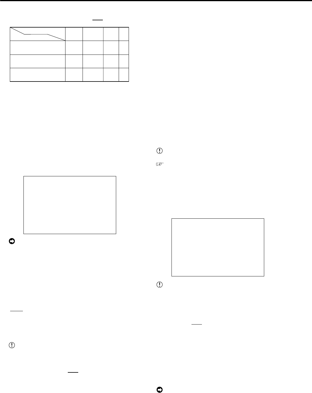
50
••••••••••••••••••••••••••••••••••••••••••••••••••••••••••••••••••••••••••••••••••••••••••••••••••••••••••••••••••••••••••••••••••••••••••••
2. Turn the JOG dial to display the desired device and turn the
SHUTTLE ring clockwise.
• The setting is confirmed and flashing stops.
3. Turn the JOG dial clockwise to move the reversed display
to the REMAIN HDD value and turn the SHUTTLE ring
clockwise.
• The background of the REMAIN HDD value turns red and
flashes.
4. Turn the JOG dial to display the desired capacity and turn
the SHUTTLE ring clockwise.
• The setting is confirmed and flashing stops.
5. Turn the SHUTTLE ring counterclockwise or press the SET
UP button.
♦ CALL OUT SETTINGS
The CALL OUT setting is a setting to notify to the out-
side warning signals outputted by this device by
outputting the signals from the CALL OUT terminal on
the rear.
CALL OUT SETTINGS use photo-coupler output
to decrease the amount of malfunctions due to wiring.
See page 15 “CALL OUT Output terminal” for apt
connection procedures.
• HDD MAIN REMAIN/HDD SUB REMAIN
When the remaining memory in the HDD reaches the
set value, the unit outputs a signal from the CALL OUT
terminal, and the “REC/REM” warning displayed on the
screen.
<CALL OUT SETTINGS>
>>
HDD MAIN REMAIN OFF
HDD MAIN FULL OFF
HDD SUB REMAIN OFF
HDD SUB FULL OFF
“HDD SUB REMAIN” is appeared when
“PARTITION” is selected on “HDD SETTING” of the
<INITIALIZATION> screen.
Setting ( default : “OFF” )
“2%”, “4%”, “6%”, “8%”, “10%”, “15%”, “20%”, “30%”,
“40%”, “50%”, “OFF”
1. Press the SET UP button
}
<SETTINGS>
}
<INITIAL SET
UP/INFORMATION>
}
<REAR TERMINAL SETTINGS>
}
Select “HDD MAIN REMAIN” or “HDD SUB REMAIN” in the
<CALL OUT SETTINGS> screen. Display the desired setting
and confirm.
2. Turn the SHUTTLE ring counterclockwise or press the SET
UP button.
By pressing the WARNING RESET button, the HDD
capacity warning from the CALL OUT terminal can be
cancelled.
Setting ( default : “OFF” )
“REMAIN”, “WARNING”, “ALARM”, “OFF”
SETTING
BUZZER
When reaching the remaining
capacity set in “REMAIN HDD”
When a failure occurs and
a warning is displayed
When an alarm recording or
emergency recording is started
REMAIN
ON
OFF
OFF
WARNING
OFF
ON
OFF
ALARM
OFF
OFF
ON
OFF
OFF
OFF
OFF
1. Press the SET UP button
}
<SETTINGS>
}
<INITIAL SET
UP/INFORMATION>
}
Select “BUZZER” in the <REAR
TERMINAL SETTINGS> screen. Display the desired setting
and confirm.
2. Turn the SHUTTLE ring counterclockwise or press the SET
UP button.
♦ REMAIN HDD
A warning indicating that the either remaining capacity
of HDD has become low during recording is outputted.
The device can be selected and the remaining capacity
can be set here.
<REAR TERMINAL SETTINGS>
MODE OUT 1 OFF
MODE OUT 2 OFF
MODE OUT 3 OFF
MODE OUT 4 OFF
MODE OUT 5 OFF
KEY SOUND ON
BUZZER OFF
>>
REMAIN HDD MAIN-10
%
CALL OUT SETTINGS
EMERGENCY REC DURATION 10M
A warning is outputted using the following methods
when the remaining capacity becomes low during re-
cording.
• The HDD usage display flashes when “3” is set to
“DISPLAY MODE” in the <TIME DATE/DISPLAY SET-
TINGS> screen.
• A buzzer will sound when “REMAIN” is set to “BUZZER”
in the <REAR TERMINAL SETTINGS> screen.
Setting of DEVICE ( default : “MAIN” )
“MAIN” : Displays a warning of low MAIN HDD capacity.
“SUB” : Displays a warning of low SUB HDD capacity.
“OFF” : Does not display warning of low capacity.
“SUB” is appeared when “PARTITION” is selected
on “HDD SETTING” of the <INITIALIZATION> screen.
Setting of “REMAIN HDD” ( default : “10%” )
“2%”, “4%”, “6%”, “8%”, “10%”, “15%”,“20%”, “30%”,
“40%”, “50%”
1. Press the SET UP button
}
<SETTINGS>
}
<INITIAL SET
UP/INFORMATION>
}
“Select “REMAIN HDD” in the <REAR
TERMINAL SETTINGS> screen and turn the SHUTTLE ring
clockwise twice.
• The setting display reverses in color when the SHUTTLE
ring is turned the first time. When the ring is turned for the
second time, the background turns red and flashes.
<INITIAL SET UP/INFORMATION> (continued)

51
ENGLISH
•••••••••••••••••••••••••••••••••••••••••••••••••••••••••••••••••••••••••••••••••••••••••••••••••••••••••••••••••••••••••••• Operations
INFORMATION
For the relationship of the warning display and CALL
OUT signal output, see pages 87,88. Although the
warning will be displayed regardless if the output item
for the CALL OUT signal is set to “Fixed”, the condition
to output CALL OUT signals can be added when the
output is set to “Selectable”. For example, the buzzer
can be set to sound when reaching a value set in “HDD
MAIN REMAIN” or “HDD SUB REMAIN” of the <CALL
OUT SETTINGS> screen if “BUZZER” in the <REAR
TERMINAL SETTINGS> screen is set to “WARNING”.
• HDD MAIN FULL/HDD SUB FULL
When the HDD is full, the CALL OUT terminal outputs a CALL
OUT signal.
<CALL OUT SETTINGS>
HDD MAIN REMAIN OFF
>>
HDD MAIN FULL OFF
HDD SUB REMAIN OFF
HDD SUB FULL OFF
“HDD SUB FULL” is appeared when the “HDD
SETTING” is selected on “PARTITION” of the <INI-
TIALIZATION> screen.
Setting ( default : “OFF” )
“ON” : Signal is outputted when the recording capacity
becomes full.
“OFF” : No signal is outputted when the recording ca-
pacity becomes full.
1. Press the SET UP button
}
<SETTINGS>
}
<INITIAL SET
UP/INFORMATION>
}
<REAR TERMINAL SETTINGS>
}
Select “HDD MAIN FULL” or “HDD SUB FULL” in the <CALL
OUT SETTINGS> screen. Display the desired setting and
confirm.
2. Turn the SHUTTLE ring counterclockwise or press the SET
UP button.
♦ EMERGENCY REC DURATION
The recording time for emergency recording can be set.
<REAR TERMINAL SETTINGS>
MODE OUT 1 OFF
MODE OUT 2 OFF
MODE OUT 3 OFF
MODE OUT 4 OFF
MODE OUT 5 OFF
KEY SOUND ON
BUZZER OFF
REMAIN HDD MAIN-10
%
CALL OUT SETTINGS
>>
EMERGENCY REC DURATION 10M
For details concerning setting EMERGENCY RE-
CORDINGS, see page 64.
Setting ( default : “10M” )
“1M”, “2M”, “5M”, “10M”, “20M”, “30M”, “60M”
1. Press the SET UP button
}
<SETTINGS>
}
<INITIAL SET
UP/INFORMATION>
}
Select “EMERGENCY REC
DURATION” in the <REAR TERMINAL SETTINGS> screen.
Display the desired setting and confirm.
2. Turn the SHUTTLE ring counterclockwise or press the SET
UP button.
■ COMMUNICATION PORT SETTINGS
<INITIAL SET UP/INFORMATION>
HDD SETTINGS
AUDIO RECORDING OFF
REAR TERMINAL SETTINGS
>>
COMMUNICATION PORT SETTINGS
INFORMATION/SERVICE
PASSWORD
LANGUAGE SELECTION
1. Press the SET UP button
}
<SETTINGS>
}
Select
“COMMUNICATION PORT SETTINGS” in the <INITIAL SET
UP/INFORMATION> screen and turn the SHUTTLE ring
clockwise.
• The <COMMUNICATION PORT SETTINGS> screen appears.
<COMMUNICATION PORT SETTINGS>
>>
RS-232C
ETHERNET
♦ RS-232C
Settings for the communication device connected to this
unit is set.
• MODE
This unit can be remote controlled from a PC connected
to the RS-232C terminal. Comments can also be inputted
from a PC for recording of comments along with the video.
<RS-232C>
>>
MODE REMOTE A
SETTINGS
Setting ( default : “REMOTE A” )
“REMOTE A” : This unit can be controlled from a PC
and every status information is returned from the unit.
“REMOTE B” : This unit can be controlled from a PC
and from the unit when the status for command is
changed.
“REMOTE C” : This unit can be controlled from a PC
with no status information.
“OFF” : This unit cannot be controlled from a PC.
1. Press the SET UP button
}
<SETTINGS>
}
<INITIAL SET
UP/INFORMATION>
}
<COMMUNICATION PORT
SETTINGS>
}
Select “MODE” in the <RS-232C> screen.
Display the desired setting and confirm.
2. Turn the SHUTTLE ring counterclockwise or press the SET
UP button.

52
••••••••••••••••••••••••••••••••••••••••••••••••••••••••••••••••••••••••••••••••••••••••••••••••••••••••••••••••••••••••••••••••••••••••••••
• SETTINGS
RS-232C settings can be made when setting “MODE”
previous to “REMOTE A”, “REMOTE B” or “REMOTE C”.
Perform settings so that the settings are the same
with the connecting PC.
Setting of “TRANSMISSION MODE” ( default : “9600” )
“1200”, “2400”, “4800”, “9600”, “19200”
Setting of “DATA BIT LENGTH” ( default : “8BIT” )
“8BIT”, “7BIT”
Setting of “PARITY BIT” ( default : “NONE” )
“NONE”, “ODD”, “EVEN”
Setting of “STOP BIT LENGTH” ( default : “1BIT” )
“1BIT”, “2BIT”
Setting of “DELIMITER” ( default : “CR” )
“CR”, “CR•LF”
1. Set “MODE” in the <RS-232C> screen to “REMOTE A”,
“REMOTE B” or “REMOTE C”.
2. Select “SETTINGS” and turn the SHUTTLE ring clockwise.
• The <RS-232C SETTINGS> screen appears.
<RS-232C SETTINGS>
>>
TRANSMISSION MODE 9600
DATA BIT LENGTH 8BIT
PARITY BIT NONE
STOP BIT LENGTH 1BIT
DELIMITER CR
3. Select the setting to change and turn the SHUTTLE ring
clockwise.
• The background of the setting turns red and flashes.
4. Display the desired sub item and turn the SHUTTLE ring
clockwise.
• The setting is confirmed and flashing stops.
5. To set other setting, repeat steps 3 and 4.
6. Turn the SHUTTLE ring counterclockwise or press the SET
UP button.
♦ ETHERNET
The IP address used to specify the connected recorder, sub
net mask setting, and MAC address can be referred to here.
Do not change the setting without sufficient knowl-
edge about the network setting.
In regard to the network settings it is recommended
to obtain advance confirmation by the network manager.
Do not assign “000.000.000.000” IP address. And
do not assign it as the broadcast address. If this address
were to be assigned, we could not guarantee
communications or any other functions of the recorder
unit.
The setting can not be changed during the record.
Stop the record to change the setting.
1. Press the SET UP button
}
<SETTINGS>
}
<INITIAL SET
UP/INFORMATION>
}
Select “ETHERNET” in the
<COMMUNICATION PORT SETTINGS> screen and turn the
SHUTTLE ring clockwise.
• The <ETHERNET> screen appears.
<ETHERNET>
>>
IP ADDRESS 192.168.000.100
SUB NET MASK 255.255.255.000
GATEWAY 000.000.000.000
E-MAIL ADDRESS
SERVICE PORT SETTING
ALARM NOTIFICATION SETTING
<MAC ADDRESS>
08-00-70-2E-3F-FF
PLEASE PRESS SET UP BUTTON
TO APPLY NEW SETTING
2. Select the setting you wish to alter by turning the JOG dial
and then turn the SHUTTLE ring clockwise.
• The leftmost number of the setting will reverse in color.
3. Turn the JOG dial to reverse display the number you wish
to alter and turn the SHUTTLE ring clockwise.
• The background of the selected number turns red and flashes.
4. Turn the JOG dial to display the desired number and turn
the SHUTTLE ring clockwise.
• The setting is confirmed and flashing stops.
5. Repeat steps 2 and 4 to change the other numbers.
6. When the setting is complete, turn the SHUTTLE ring
counterclockwise.
• The cursor move to setting directly to the left.
7. (Finalizing updated menu settings • • • )
When any setting of “IP ADDRESS”, “SUB NET MASK”,
“GATEWAY” is changed, press ths SET UP button.
• The power turns off automatically, then the unit will boot up.
Press the SET UP button to return to the normal
screen without changing the setting.
• E-MAIL ADDRESS
The contents of the setting of “SMTP SERVER”, “RE-
CORDER ID” and “USER ADDRESS” can be referred
to here.
The specific software is required to input “SMTP
SERVER”, “RECORDER ID” and “USER ADDRESS”.
Please refer to the instruction manual of the software.
1. Press the SET UP button
}
<SETTINGS>
}
<INITIAL SET
UP/INFORMATION>
}
<COMMUNICATION PORT SETTING>
}
select “E-MAIL ADDRESS” in the <ETHERNET> screen.
• The <E-MAIL ADDRESS> screen appears.
<E-MAIL ADDRESS>
SMTP SERVER
RECORDER ID
USER ADDRESS
1
2
3
4
5
“USER ADDRESS” is displayed only for 20 charac-
ters from the beginning.
<INITIAL SET UP/INFORMATION> (continued)

53
ENGLISH
•••••••••••••••••••••••••••••••••••••••••••••••••••••••••••••••••••••••••••••••••••••••••••••••••••••••••••••••••••••••••••• Operations
• SERVICE PORT SETTING
The port number can be set here to connect personal
computer.
Do not change the setting without sufficient knowl-
edge about the network setting.
When perform other setting except “WEB”, the spe-
cific software is required. Please refer to the instruc-
tion manual of the software.
1. Press the SET UP button
}
<SETTINGS>
}
<INITIAL SET
UP/INFORMATION>
}
<COMMUNICATION PORT
SETTINGS>
}
select “SERVICE PORT SETTING” in the
<ETHERNET> screen.
• The <SERVICE PORT SETTING> screen appears.
<SERVICE PORT SETTING>
>>
WEB •00080
USER ACCESS 53705
SUPER USER 53706
LIVE USER1 53707
LIVE USER2 53708
LIVE USER3 53709
LIVE USER4 53710
2. Turn the JOG dial to select the desired setting and turn the
SHUTTLE ring clockwise.
• The first figure of the port number reverses in color.
3. Turn the JOG dial to display the desired figure reversed in
color, and turn the SHUTTLE ring clockwise.
• The background of the selected figure turns red and flashes.
4. Turn the JOG dial to display the desired port number and
turn the SHUTTLE ring clockwise.
• The setting is confirmed and flashing stops
5. Turn the SHUTTLE ring counterclockwise.
• The cursor appears to the setting on the left.
When change the “WEB” setting, the “ • ” situated
on the left of the port number turns its color from green
to red.
6. To change other settings repeat steps 2 to 5.
7. (Finalizing update menu settings • • • )
Return to the <ETHERNET> screen by turning the SHUTTLE
ring counterclockwise and press the SET UP button.
• The power turns off automatically, then the unit will boot
up.
Press the SET UP button to return to the normal
screen without changing the setting.
• ALARM NOTIFICATION SETTING
The setting is for the transmission of warning signals and
other signals for status changes such as the short-circuit
of the rear terminal or when initiated the recording.
The specific software is required. Please refer to
the instruction manual of the software.
Issuing of reports to broadcast addresses is not
supported.
1. Press the SET UP button
}
<SETTINGS>
}
<INITIAL SET
UP/INFORMATION>
}
<COMMUNICATION PORT
SETTING>
}
select “ALARM NOTIFICATION SETTING” in
the <ETHERNET> screen.
• The <ALARM NOTIFICATION SETTING> screen appears.
<ALARM NOTIFICATION SETTING>
NO IP ADDRESS TARGET OWN
>>
1 000.000.000.000•55111 01111
2 000.000.000.000•55111 01112
3 000.000.000.000•55111 01113
4 000.000.000.000•55111 01114
5 000.000.000.000•55111 01115
WARNING OFF
ALARM SENS OFF
REC MODE OFF
RETRY TIME 10S
2. (Cases of setting the IP ADDRESS number of connected
PC, the port setting number, etc. • • • )
Turn the JOG dial to select the desired setting number and
turn the SHUTTLE ring clockwise.
• The leftmost figure of the port number reverses in color.
3. Turn the JOG dial to display the desired figure of numbers
of IP ADDRESS, TARGET PORT and OWN PORT reversed
in color and turn the SHUTTLE ring clockwise.
• The background of the desired figure turns red and flashes.
4. Turn the JOG dial to display the desired number and turn
the SHUTTLE ring clockwise.
• The setting is confirmed and flashing stops
5. Turn the SHUTTLE ring counterclockwise.
• The cursor appears to the setting on the left.
When TARGET PORT number is set to 00000 -
01023, the “ • ” situated on the left of the value turns red
from green, and in case of 01024 - 49151 turns yellow.
6. To change other setting number repeat steps 2 to 5.
7. (Cases of the setting of the transmission contents to
connected PC • • • )
Turn the JOG dial to select the desired setting and turn the
SHUTTLE ring clockwise.
• The background of the setting turns red and flashes.
Setting of “WARNING” ( default : “OFF” )
“ON” : Transmits warning signals to connected PC. E-
mail is sent to address displayed on “USER ADDRESS”
of the <E-MAIL ADDRESS> screen.
“OFF” : Does not transmit.
Setting of “ALARM SENS” ( default : “OFF” )
“ON” : Only for the short-circuit of rear terminal trans-
mits the status information to connected PC. E-mail is
sent to address displayed on “USER ADDRESS” of the
<E-MAIL ADDRESS> screen.
“OFF” : Does not transmit.
Setting of “REC MODE” ( default : “OFF” )
“ON” : Transmits the recording status such as normal
recording or alarm recording to connected PC. E-mail
is sent to address displayed on “USER ADDRESS” of
the <E-MAIL ADDRESS> screen.
OFF : Does not transmit.
Setting of “RETRY TIME” ( default : “10S” )
1S, 2S, • • • •, 10S, • • • • • • 59S, 60S

54
••••••••••••••••••••••••••••••••••••••••••••••••••••••••••••••••••••••••••••••••••••••••••••••••••••••••••••••••••••••••••••••••••••••••••••
8. Turn the JOG dial to display the desired setting and turn the
SHUTTLE ring clockwise.
• The setting is confirmed and stops flashing.
9. (Finalizing update menu settings of the transmission
contents • • • )
Return to the <ETHERNET> screen by turnning the SHUTTLE
ring counterclockwise and turn the SHUTTLE ring
counterclockwise or press the SET UP button.
10. (Finalizing update menu settings of number of IP
ADDRESS , TRAGET PORT or OWN PORT • • • )
Return to the <ETHERNET> screen by turnning the SHUTTLE
ring counterclockwise and press the SET UP button.
• The power turns off automatically, then the unit will boot
up.
Press the SET UP button to return to the normal
screen without changing the setting.
■ INFORMATION/SERVICE
The <INFORMATION/SERVICE> screen is used to
check log and device lists after power failure, and ini-
tialization the menu. The total operating time is displayed
on the 2/2 screen.
<INFORMATION/SERVICE> 1/2
<INFORMATION/SERVICE> (1/2)
>>
HDD INFORMATION
CFC INFORMATION
WARNING LOG LIST
RESET TO FACTORY SETTINGS
MAIN HDD DATA CLEAR
SUB HDD DATA CLEAR
CFC DATA CLEAR
<INFORMATION/SERVICE> 2/2
<INFORMATION/SERVICE> (2/2)
ELAPSED TIME: SYSTEM 3H
HDD SETTING PARTITION
PARTITION SIZE 10%
The <INFORMATION/SERVICE> screen consists
of 2 pages. The second page is appeared by turning
the JOG dial clockwise when the cursor points out the
setting of the bottom of the screen.
“SUB HDD DATA CLEAR” is appeared on page
1/2 of the <INFORMATION/SERVICE> screen when
“PARTITION” is selected on “HDD SETTING” of the
<INITIALIZATION> screen.
“PARTITION SIZE” is appeared on page 2/2 of the
<INFORMATION/SERVICE> screen when
“PARTITION” is selected on “HDD SETTING” of the
<INITIALIZATION> screen.
♦ HDD INFORMATION/CFC INFORMATION
INFORMATION is used to check the amount of
available space in the HDD and Compact Flash Cards
inserted into the unit.
1-1. (To check HDD RECORD data • • • )
Press the SET UP button
}
<SETTINGS>
}
<INITIAL SET
UP/INFORMATION>
}
Select “HDD INFORMATION” in the
<INFORMATION/SERVICE> (1/2) screen, and turn the
SHUTTLE ring clockwise.
• The <HDD INFORMATION> screen is displayed.
<HDD INFORMATION>
INTERNAL HDD
MASTER: HDD(250GB)
SLAVE : NONE
MAIN START ---------- --:--:--
END ---------- --:--:--
SUB START ---------- --:--:--
END ---------- --:--:--
Recording start and end times of “SUB” area is ap-
peared when the “HDD SETTING” is selected on
“PARTITION” of the <INITIALIZATION> screen.
1-2
.
(To check RECORD data of the Compact Flash Card
inserted into the unit or whether MENU INFORMATION is
recorded • • • )
Press the SET UP button
}
<SETTINGS>
}
<INITIAL SET
UP/INFORMATION>
}
Select “CFC INFORMATION” in the
<INFORMATION/SERVICE> (1/2) screen, and turn the
SHUTTLE ring clockwise.
• The <CFC INFORMATION> screen of the Compact Flash Card
inserted into the unit is displayed.
<CFC INFORMATION>
CFC
CAPACITY 128MB
START ---------- --:--:--
END ---------- --:--:--
MENU INFORMATION is appeared on the screen
when there is recorded MENU INFORMATION.
2.Turn the SHUTTLE ring counterclockwise or press the SET
UP button.
♦ WARNING LOG LIST
The WARNING LOG LIST enables to check the number
of failure, date, time and type of failure, etc.
<INFORMATION/SERVICE> (1/2)
HDD INFORMATION
CFC INFORMATION
>>
WARNING LOG LIST
RESET TO FACTORY SETTINGS
MAIN HDD DATA CLEAR
SUB HDD DATA CLEAR
CFC DATA CLEAR
<INITIAL SET UP/INFORMATION> (continued)

55
ENGLISH
•••••••••••••••••••••••••••••••••••••••••••••••••••••••••••••••••••••••••••••••••••••••••••••••••••••••••••••••••••••••••••• Operations
1. Press the SET UP button
}
<SETTINGS>
}
<INITIAL SET
UP/INFORMATION>
}
Select “WARNING LOG LIST” in the
<INFORMATION/SERVICE> (1/2) screen. Turn the SHUTTLE
ring clockwise.
• The <WARNING LOG LIST> screen appears.
• The WARNING LOG LIST can display up to 1000 items. When
the number of items exceed this limit, the latest 1000 items
are displayed.
• button/turn JOG dial counterclockwise : Selection moves
to the next number.
• button/turn JOG dial clockwise : Selection moves to the
previous number.
• button : Displays the page with date prior to the date of
the currently opened page.
• button : Displays the page with date newer than the date
of the currently opened page.
When a failure occurs while the <WARNING LOG
LIST> is being displayed, exit the screen and display
the screen again. A new item will be added to the list.
Failures displayed in the WARNING LOG LIST
( see pages 87,88).
<WARNING LOG LIST>
NO DATE TIME WARNING
>>
0001 02-02-04 10:00:00 ALM ON
<The “WARNING” are displayed in red.>
• “P-LOSS” : Power failure.
• “SYS RST” : Reset button was pressed and the unit
was reset.
<The “WARNING” are displayed in green.>
• “ALM OFF” : The ALARM INTERRUPT button was
pressed and the unit was put on interruption.
• “ALM ON” : The ALARM INTERRUPT button was
pressed and the alarm interrupt was cancelled.
• “REC ON” : The record was started.
• “REC OFF” : The record was stopped.
• “PS-OFF” : PASSWORD LOCK was unlocked.
• “PS-1” : The PASSWORD level 1 was locked.
• “PS-2” : The PASSWORD level 2 was locked.
• “PS-3” : The PASSWORD level 3 was locked.
• “PS-4” : The PASSWORD level 4 was locked.
• “PS-E” : The SIMPLE LOCK was locked.
When recording is started, “REC ON” is registered
in <WARNING LOG LIST>. However, “REC ON” will
not be registered when recording is resumed after
power is restored.
For power outages that occur while timer recording
is standing by, “P-LOSS” that indicates a power outage
is not displayed. In addition, power outages that overlap
with timer recording start times and those where power
is restored after the recording end time are also not
recorded.
2. Turn the SHUTTLE ring counterclockwise or press the SET
UP button.
♦ RESET TO FACTORY SETTINGS
Menu screen settings are reset.
1. Press the SET UP button
}
<SETTINGS>
}
<INITIAL SET
UP/INFORMATION>
}
Select “RESET TO FACTORY
SETTINGS” in the <INFORMATION/SERVICE> (1/2) screen.
Turn the SHUTTLE ring clockwise.
• The <RESET TO FACTORY SETTINGS> screen appears.
• When not resetting menu screen settings, turn the SHUTTLE
ring counterclockwise.
<RESET TO FACTORY SETTINGS>
>>
EXECUTE
SHUTTLE>>:EXECUTE,<<:CANCEL
2. Turn the SHUTTLE ring clockwise.
• The menu screen settings are reset.
The <TIMER PROGRAM> setting is not initialized.
When menu initialization is performed when a
setting change has been made for any one item of “IP
ADDRESS”, “SUB NET MASK”, “GATEWAY”,
“SERVICE PORT SETTING” on the <ETHERNET>
screen or “IP ADDRESS”, “TARGET” or “OWN” of the
<ALARM NOTIFICATION SETTING> settings, restart
is performed after the power has been cut.
3. Turn the SHUTTLE ring counterclockwise or press the SET
UP button.
♦ DATA CLEAR
For deleting data in MAIN HDD, SUB HDD or CFC (Com-
pact Flash Card).
“SUB HDD DATA CLEAR” is appeared when the
“HDD SETTING” is selected on “PARTITION” of the
<INITIALIZATION> screen.
Performing “MAIN HDD DATA CLEAR” while in
“MIRRORING” mode deletes all data.
1. Press the SET UP button
}
<SETTINGS>
}
<INITIAL
SET UP/INFORMATION>
}
Select the desired item to clear
in the <INFORMATION/SERVICE> (1/2) screen. Turn the
SHUTTLE ring clockwise.
• “PUSH WARNING RESET KEY FOR 1 SECOND TO CLEAR”
appears on the bottom of the screen.
• To cancel the deletion, turn the SHUTTLE ring counter-
clockwise.
<MAIN HDD DATA CLEAR>
PUSH WARNING RESET KEY
FOR 1 SECOND TO CLEAR

56
••••••••••••••••••••••••••••••••••••••••••••••••••••••••••••••••••••••••••••••••••••••••••••••••••••••••••••••••••••••••••••••••••••••••••••
When a password for level 4 has been registered
and locked, and the settings for “MAIN HDD DATA
CLEAR” and “SUB HDD DATA CLEAR” are made, the
<UNLOCK PASSWORD> screen will be displayed and
the lock must be unlocked.
2. Press the WARNING RESET button for 1 second.
• “CLEARING ...” appears on the screen.
Data cannot be erased when accessing to HDD as
playing/recording/copying/restoring.
3. Turn the SHUTTLE ring counterclockwise or press the SET
UP button.
■ PASSWORD
The unit is equipped with 2 lock functions : SIMPLE
LOCK that does not require the PASSWORD when un-
locking and PASSWORD LOCK that require the PASS-
WORD when unlocking.
• If the PASSWORD for unlocking has not been set :
Lock function will be SIMPLE LOCK
• If the PASSWORD for unlocking has been set : Lock
function will be PASSWORD LOCK.
When the MAIN switch on the rear of the unit is set
to ON, SIMPLE LOCK/PASSWORD LOCK setting can
be made even with the POWER button on the front set
to OFF.
When the MAIN switch on the rear of the unit is set
to OFF or when a menu is being displayed, SIMPLE
LOCK/PASSWORD LOCK will not function.
♦ SIMPLE LOCK
When SIMPLE LOCK is on, buttons other than the
SPLIT/SEQUENCE button, ZOOM button, camera
number buttons 1 ~ 9 and the MAIN switch become
inoperable and the unit will be locked in the current state.
To apply simple lock • • •
1. Press the LOCK button using a ballpoint pen, etc., when
the MAIN switch is set to ON.
• The lock turns on and the LOCK indicator lights.
To unlock simple lock • • •
1. Press the LOCK button.
• The lock is unlocked and the LOCK indicator turns off.
♦ PASSWORD LOCK
PASSWORD LOCK is divided into the two types of “OP-
ERATION CONTROL” and “HDD DATA CLEAR”. “OP-
ERATION CONTROL” can be locked in three levels by
operation functions. “HDD DATA CLEAR” makes it possi-
ble to lock the settings “MAIN HDD DATA CLEAR” and
“SUB HDD DATA CLEAR”.
<About PASSWORD LOCK for OPERATION CON-
TROL (level 1 to level 3)>
1) Input the PASSWORD of level 1 to level 3.
2) Set the PASSWORD LOCK.
• The PASSWORD LOCK of level 1 will be active.
When The PASSWORD LOCK of level 1 is active,
functions of all operations can be locked.
3) Unlock the PASSWORD LOCK of level 1.
• The PASSWORD LOCK of level 2 will be active.
When The PASSWORD LOCK of level 2 is active,
only the SPLIT/SEQUENCE button, ZOOM button and
camera number buttons are operable.
4) Unlock the PASSWORD LOCK of level 2.
• The PASSWORD LOCK of level 3 will be active.
When The PASSWORD LOCK of level 3 is active,
it is operable except the SET UP button and ALARM
INTERRUPT button.
5) Unlock the PASSWORD LOCK of level 3.
• The PASSWORD LOCK of all levels will be unlocked.
Functions of all operations can be operable.
For level 1 and level 2, press the LOCK button on
the front of the unit to display the <UNLOCK PASS-
WORD> screen. Input the PASSWORD to unlock. For
level 3, press the SET UP button to display the <UN-
LOCK PASSWORD> screen and input the
PASSWORD. When don’t cancel the password lock, it
is in the state where the <UNLOCK PASSWORD>
screen is displayed, and please press the LOCK button.
When the MAIN switch (main power) on the rear is
set to ON, the PASSWORD can be registered, set and
cancelled even with the POWER button on the front is
set to OFF.
To register the PASSWORD • • •
The PASSWORD is registered using a 4 digit number
using numbers from 0 ~ 9.
1. Press the SET UP button
}
<SETTINGS>
}
Select
“PASSWORD” in the <INITIAL SET UP/INFORMATION> screen.
• The <PASSWORD> screen appears.
<PASSWORD>
>>
OPERATION CONTROL
HDD DATA CLEAR
2-1. ( To register the PASSWORD for OPERATION CONTROL
for (level 1 to level 3) • • • )
Confirm the cursor is positioned at left side of “OPERATION
CONTROL”, turn the SHUTTLE ring clockwise.
• The <PASSWORD SETTING> screen appears.
<PASSWORD SETTING>
FIRST SECOND
>>
1 ---- ----
2 ---- ----
3 ---- ----
PRESS WARNING RESET BUTTON
TO CLEAR PASSWORD
SHUTTLE>>:TO SET PASSWORD
<INITIAL SET UP/INFORMATION> (continued)
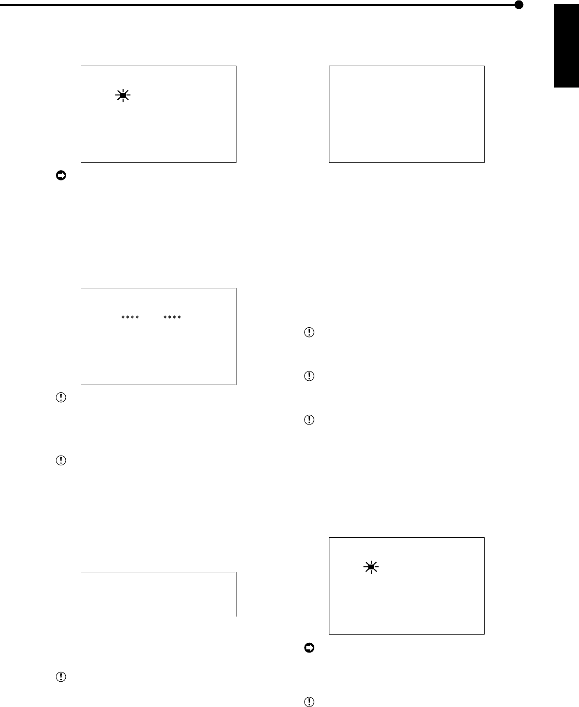
57
ENGLISH
•••••••••••••••••••••••••••••••••••••••••••••••••••••••••••••••••••••••••••••••••••••••••••••••••••••••••••••••••••••••••••• Operations
2-2. Confirm the cursor is moved to the left side of the level “1” ,
turn the SHUTTLE ring clockwise.
• The first input position of “FIRST” will be displayed in
reversed color and flashes.
<PASSWORD SETTING>
FIRST SECOND
1 ---- ----
2 ---- ----
3 ---- ----
PRESS CAMERA BUTTON TO ENTER
PASSWORD
The PASSWORD may consist of the numbers from
1 to 9 which are assigned to the camera number but-
tons. 0 is assigned to the ZOOM button.
2-3. Input 4 digits of the PASSWORD by pressing the camera
number buttons and the ZOOM button.
• The first input position of “SECOND” will be displayed
reversed color and flashs.
2-4. Input the PASSWORD entered in “FIRST” in “SECOND”.
• The cursor moves to the left side of the setting of level 1.
<PASSWORD SETTING>
FIRST SECOND
>>
1
2 ---- ----
3 ---- ----
PRESS WARNING RESET BUTTON
TO CLEAR PASSWORD
SHUTTLE>>:TO SET PASSWORD
Input the same number in “FIRST” and “SECOND”.
The setting returns to step 2 if the different PASSWORD
number is inputted.
2-5. Repeat steps 2-2 ~ 2-4 to set level 2 and level 3.
It is not necessary to input the PASSWORD all lev-
els 1, level 2 and level 3. Input the PASSWORD in the
desired level only.
2-6. Turn the SHUTTLE ring counterclockwise.
3-1. ( To register the PASSWORD for HDD DATA CLEAR for
(level 4) • • • )
Turn the JOG dial to move the cursor to “HDD DATA CLEAR”,
turn the SHUTTLE ring clockwise.
• The <PASSWORD SETTING> screen appears.
<PASSWORD SETTING>
FIRST SECOND
>>
4 ---- ----
3-2. Repeat steps 2-2 ~ 2-4 to set level 4.
4. Turn the SHUTTLE ring counterclockwise, or press the
SET UP button.
The password lock for HDD data deletion (level
4) becomes effective when leaving the setting
screen.
To unlock the PASSWORD • • •
1. ( To unlock the PASSWORD for level 1 and level 2 • • • )
Press the LOCK button.
• The <UNLOCK PASSWORD> screen appears.
<UNLOCK PASSWORD>
>>
1 ----
2 ----
EXECUTE
SHUTTLE>>:TO SET PASSWORD
2. Confirm the cursor is moved to the left side of level “1” and
turn the SHUTTLE ring clockwise.
• The first digit reverse in color.
3. Input 4 digits of the PASSWORD by pressing the camera
number buttons or the ZOOM button.
• The cursor moves to the left side of the setting of level 1.
4. Turn the JOG dial to select the level “2” and turn the
SHUTTLE ring clockwise.
• The first input position will be displayed reversed color.
5. Input the 4 digits of the PASSWORD by pressing the
camera number buttons or the ZOOM button.
• The cursor moves to the left side of the setting “2”.
When the PASSWORD LOCK of level 1 and level 2
are set, if unlock level 1 the PASSWORD LOCK of level
2 will be active.
When the PASSWORD LOCK of level 1 and level
2 are set, level 2 only can not be unlocked. Be sure to
unlock level 1 too.
Input the PASSWORD correctly. If there is an error
in input, repeat steps 4 and 5 to input again.
6. Turn the JOG dial to move the cursor to “EXECUTE” and
turn the SHUTTLE ring clockwise.
• The PASSWORD LOCK is unlocked and turns off the LOCK
indicator.
• The normal screen is returned.
7. ( To unlock the PASSWORD for level 3 • • • )
Press the SET UP button.
• The <UNLOCK PASSWORD> screen appears.
<UNLOCK PASSWORD>
3 ----
PRESS CAMERA BUTTON TO ENTER
PASSWORD
When the PASSWORD LOCK of level 1, level 2
and level 3 are set, the PASSWORD LOCK of level 2
will be active in case of unlocking level 1 , and level 3
will be active in case of unlocking level 1 and level 2.
When the PASSWORD LOCK of level 1, level 2
and level 3 are set, level 3 only can not be unlocked.
Be sure to unlock level 1 and level 2 too.
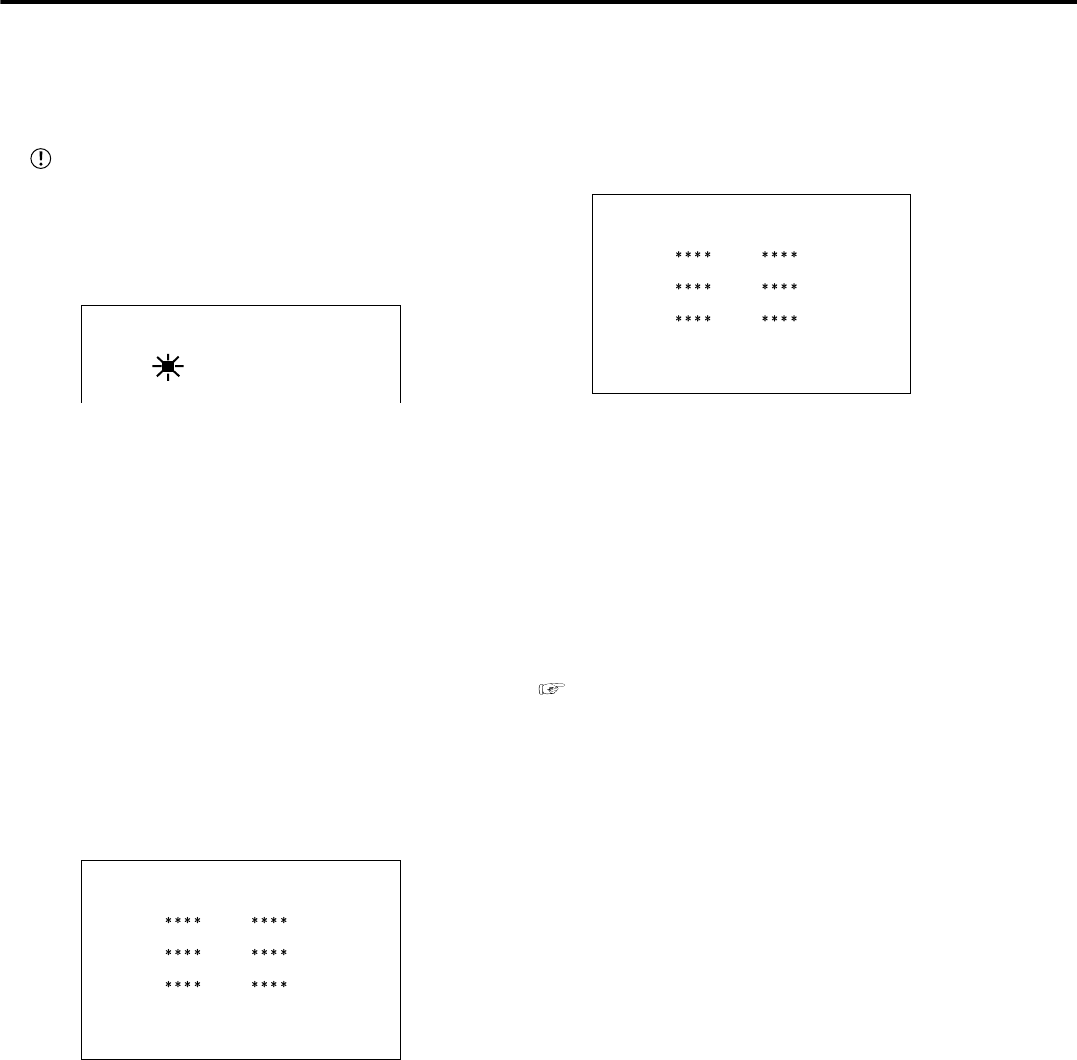
58
••••••••••••••••••••••••••••••••••••••••••••••••••••••••••••••••••••••••••••••••••••••••••••••••••••••••••••••••••••••••••••••••••••••••••••
8. Input the 4 digits of the PASSWORD number by pressing
the camera number buttons or the ZOOM button.
• The PASSWORD LOCK is unlocked and turns off the LOCK
indicator.
• The normal screen is returned.
Press the LOCK button to return to the normal
screen without input PASSWORD.
9. ( To unlock the PASSWORD for level 4 • • • )
Set “MAIN HDD DATA CLEAR” or “SUB HDD DATA CLEAR”
at the <INFORMATION/SERVICE> (1/2) screen.
• The <UNLOCK PASSWORD> screen appears.
<UNLOCK PASSWORD>
4 ----
10. Input the 4 digits of the PASSWORD number by pressing
the camera number buttons or the ZOOM button.
• The PASSWORD LOCK is unlocked and DATA CLEAR screen
appears.
To lock the PASSWORD (only level1 to level 3) • • •
1. Press the LOCK button using a ballpoint pen, etc., when
the MAIN switch is set to ON.
• The PASSWORD LOCK is applied and the LOCK indicator lights.
To change the PASSWORD • • •
1. Unlock the PASSWORD of level 1 to level 3 to display the
<PASSWORD SETTING> screen.
2-1. (To change the PASSWORD for level 1 to level 3 • • • )
Display the <PASSWORD SETTING> (level 1 to level 3)
screen. Turn the JOG dial to move the cursor to desired level
to change the PASSWORD number and press the WARNING
RESET button.
• The PASSWORD in “FIRST” and “SECOND” are cleared to
appear “- - - -”.
<PASSWORD SETTING>
FIRST SECOND
>>
1
2
3
PRESS WARNING RESET BUTTON
TO CLEAR PASSWORD
SHUTTLE>>:TO SET PASSWORD
2-2. Input the new PASSWORD referring to “To register the
PASSWORD • • •”.
3-1. (To change the PASSWORD for level 4 • • • )
Display the <PASSWORD> screen. Turn the JOG dial to move the
cursor to cursor to “HDD DATA CLEAR”, and turn SHUTTLE ring
clockwise.
• The <CHANGE PASSWORD> screen appears.
3-2. Input the 4 digits of the PASSWORD number by pressing
the camera number buttons or the ZOOM button.
• The PASSWORD LOCK is unlocked and <PASSWORD
SETTING> screen appears.
3-3. Press the WARNING RESET button.
• The PASSWORD in “FIRST” and “SECOND” are cleared to
appear “- - - -”.
3-4. Input the new PASSWORD referring to “To register the
PASSWORD • • •”.
Changing from PASSWORD LOCK mode to
SIMPLE LOCK mode • • •
1.Unlock the PASSWORD of level 1 to level 3 to display the
<PASSWORD SETTING> screen.
<PASSWORD SETTING>
FIRST SECOND
>>
1
2
3
PRESS WARNING RESET BUTTON
TO CLEAR PASSWORD
SHUTTLE>>:TO SET PASSWORD
2. Confirm the cursor is at the left side of level 1 and press the
WARNING RESET button.
• The PASSWORD in “FIRST” and “SECOND” are cleared to
appear “- - - -”.
3. Turn the JOG dial to move the cursor to level 3 after level 2
press the WARNING RESET button.
• The PASSWORD of all levels are changed to display “- - - -”.
4. Turn the SHUTTLE ring counterclockwise or press the SET
UP button.
■ LANGUAGE SELECTION
See Page 25.
<INITIAL SET UP/INFORMATION> (continued)
59
ENGLISH
•••••••••••••••••••••••••••••••••••••••••••••••••••••••••••••••••••••••••••••••••••••••••••••••••••••••••••••••••••••••••••• Operations
■ QUICK SETTINGS
Menu settings stored on the Compact Flash Card can
be read and altered with the unit. Menu settings in the
unit can be copied to the Compact Flash Card.
During execution of menu quick settings, other op-
erations are not accepted.
♦ To update menu settings of this unit
To read/alter menu settings stored on the Compact
Flash Card using the unit, synchronize the HDD setting
to that of the unit the menu settings were copied to. The
HDD setting that needs to be synchronized is the “HDD
SETTING”, and “PARTITION SIZE”.
If the HDD settings are not synchronized, the menu
settings are not updated.
1. Insert a Compact Flash Card recorded with menu settings
into the COMPACT FLASH slot of this unit.
2. Select “QUICK SETTINGS” in the <SETTINGS> screen and
turn the SHUTTLE ring clockwise.
• The <QUICK SETTINGS> screen appears.
<QUICK SETTINGS>
>>
LOAD SETTING DATA FROM CFC
SAVE SETTING DATA TO CFC
3. Select “LOAD SETTING DATA FROM CFC” and turn the
SHUTTLE ring clockwise.
• The <SETTING DATA LOADING> screen appears.
• To cancel the update of menu settings, turn the SHUTTLE
ring counterclockwise.
<SETTING DATA LOADING>
>>
EXECUTE
SHUTTLE>>:EXECUTE,<<:BACK
4. Turn the SHUTTLE ring clockwise.
• The menu settings of this unit is updated and
<<COMPLETED>> appears on the screen.
• When no Compact Flash Card has been inserted <<MEDIA
NONE>> will appear on the screen.
Turn off POWER to finalize updated menu settings.
When data with setting changes for any one item
of “IP ADDRESS”, “SUB NET MASK”, “GATEWAY”,
“SERVICE PORT SETTING” on the <ETHERNET>
screen or “IP ADDRESS”, “TARGET” or “OWN” of the
<ALARM NOTIFICATION SETTING> settings are read
out or when settings are changed, restart is performed
after the power has been cut.
After menu read-out has been completed, the time
is not reflected and the correct time should be set.
5. (Finalizing updated menu settings • • • )
Turn the SHUTTLE ring counterclockwise three times, or return
to normal screen by pressing the SET UP button.
6. Press the POWER button to turn the unit off, then press it
once more to turn the unit back on.
• The setting is confirmed.
♦ To save menu settings of this unit to a Compact
Flash Card
1. Insert a Compact Flash Card into the COMPACT FLASH
slot of this unit.
2. Select “QUICK SETTINGS” in the <SETTINGS> screen and
turn the SHUTTLE ring clockwise.
• The <QUICK SETTINGS> screen appears.
3. Select “SAVE SETTING DATA TO CFC” and turn the
SHUTTLE ring clockwise.
• The <SETTING DATA SAVING> screen appears.
• When not saving the menu settings to the Compact Flash
Card, turn the SHUTTLE ring counterclockwise.
<SETTING DATA SAVING>
>>
EXECUTE
SHUTTLE>>:EXECUTE,<<:BACK
4. Turn the SHUTTLE ring clockwise.
• The menu settings are overwritten in the Compact Flash
Card and <<COMPLETED>> appears on the screen.
• When no Compact Flash Card has been inserted <<MEDIA
NONE>> will appear on the screen.
5. Turn the SHUTTLE ring counterclockwise or press the SET
UP button.
Menu read-out, setting change, and menu copying
can be performed only when this unit is stopped (stop
of playback/recording/communication).
For LOAD/SAVE in the menu sometimes it takes a
few seconds immediately after perform “EXECUTE”.
<QUICK SETTINGS>
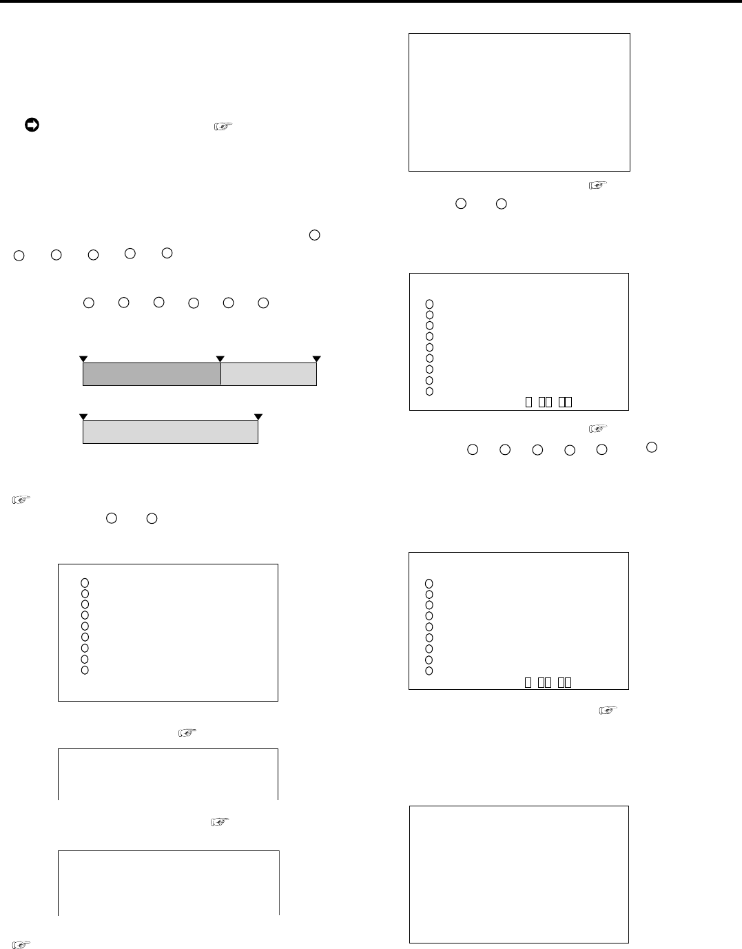
60
••••••••••••••••••••••••••••••••••••••••••••••••••••••••••••••••••••••••••••••••••••••••••••••••••••••••••••••••••••••••••••••••••••••••••••
Operation examples
■ Operation example 1
This example illustrates the procedure for switching be-
tween cameras according to time and day, when different
numbers of cameras are allocated to RECORD SETTINGS
A and B for normal recording in Timer record mode.
For loading of camera video, see “Relation
of recording operation to the number of cameras
and recording interval settings”, page 89.
< Operation >
• REC MODE A (normal recording with all cameras) is
set to Monday ~ Friday from 08:00 to 15:00 and REC
MODE B (normal recording with camera number “
1
”,
“
2
”, “
3
”, “
7
”, “
8
”, “
9
” ) is set to 15:00 ~ 20:00.
• On weekends, REC MODE B (normal recording with cam-
era number “
1
”, “
2
”, “
3
”, “
7
”, “
8
”, “
9
” ) is set to
08:00 ~ 17:00.
From Monday
to Friday
Saturday and
Sunday
08:00 17:00
08:00 15:00 20:00
REC MODE A
REC MODE B
REC MODE B
< Setting >
1) <CAMERA TITLE/MEMO SETTING> screen setting
( see pages 32,33).
• All cameras ( “
1
” ~ “
9
” ).
• Input title.
<CAMERA TITLE/MEMO SETTING>
9
7
4
5
6
1
2
3
8
<CAMERA TITLE/MEMO SETTING>
ENTRANCE1
ENTRANCE2
VAULT
COUNTER1
COUNTER2
COUNTER3
EXIT1
EXIT2
>>
PARKING
MEMO ••••••••••••••••
SHUTTLE>>:CHARACTERS
2) <INITIAL SET UP/INFORMATION> screen setting.
• AUDIO RECORDING : “OFF” ( see page 48)
<INITIAL SET UP/INFORMATION>
HDD SETTINGS
>>
AUDIO RECORDING OFF
REAR TERMINAL SETTINGS
3) <HDD SETTINGS> screen setting ( see pages 47,48 ).
• HDD REPEAT REC MAIN : “ON”.
<HDD SETTINGS>
>>
HDD REPEAT REC MAIN ON
HDD REPEAT REC SUB OFF
HDD REPEAT PLAY OFF
IM-CHECK PLAY OFF
4) <TIMER PROGRAM SETTINGS> screen setting
( see pages 44-46).
• SELECTED PATTERN : “P1”.
<TIMER PROGRAM SETTINGS>
>>
SELECTED PATTERN P1-SET
HOLIDAY SETTING
REC MODE A
REC MODE B
REC MODE C
REC MODE D
ALARM REC DURATION 5S
5) <RECORD SETTING A> screen setting ( see page 46).
• All cameras ( “
1
” ~ “
9
” ).
• PPS, GRADE : Set desired interval and picture quality
for each camera.
• A-PPS : “- - - - - -”.
<RECORD SETTING A>
9
7
4
5
6
1
2
3
8
<RECORD SETTING A>
ALARM CH
NO PPS GRADE A-PPS A-GRADE
2.5P STD ------ STD
2.5P STD ------ STD
2.5P STD ------ STD
2.5P STD ------ STD
2.5P STD ------ STD
2.5P STD ------ STD
2.5P STD ------ STD
2.5P STD ------ STD
>>
2.5P STD ------ STD
<ESTD REC> D H M
6) <RECORD SETTING B> screen setting ( see page 46).
• Camera number “
1
”, “
2
”, “
3
”, “
7
”, “
8
” and “
9
”
only.
• PPS, GRADE : Set desired interval and picture quality
for each camera.
• A-PPS : “- - - - - -”.
• Other camera.
• PPS, A-PPS : “- - - - - -”.
<RECORD SETTING B>
9
7
4
5
6
1
2
3
8
<RECORD SETTING B> ALARM CH
NO PPS GRADE A-PPS A-GRADE
4.165P
SUPER ------ STD
4.165P
SUPER ------ STD
4.165P
SUPER ------ STD
------ STD ------ STD
------ STD ------ STD
------ STD ------ STD
4.165P
SUPER
------ STD
4.165P
SUPER ------ STD
>>
4.165P
SUPER ------ STD
<ESTD REC> D H M
7) <TIMER PROGRAM> screen setting ( see pages
44,45).
• PROGRAM NO.1 : “SPL”, “08:00”, “15:00”, “A”, “OFF”.
• PROGRAM NO.2 : “SPL”, “15:00”, “20:00”, “B”, “OFF”.
• PROGRAM NO.3 : “SAT”, “08:00”, “17:00”, “B”, “OFF”.
• PROGRAM NO.4 : “SUN”, “08:00”, “17:00”, “B”, “OFF”.
• SPL : “MON - FRI”.
<TIMER PROGRAM> P1
DW START END MODE MD
1
SPL 08:00 15:00 A OFF
2
SPL 15:00 20:00 B OFF
3
SAT 08:00 17:00 B OFF
4
SUN 08:00 17:00 B OFF
5 --- --:-- --:-- ---- -
6 --- --:-- --:-- ---- -
7 --- --:-- --:-- ---- -
8 --- --:-- --:-- ---- -
>>
SPL MON-FRI
When completed with all settings above and after clear-
ing the menu screen, press the TIMER button. The unit
will switch to the timer mode.

61
•••••••••••••••••••••••••••••••••••••••••••••••••••••••••••••••••••••••••••••••••••••••••••••••••••••••••••••••••••••••••••• Operations
ENGLISH
■ Operation example 2
This example uses the holiday setting.
< Operation >
• REC MODE A (normal recording with camera number
“
1
” ~ “
9
” ) is set to Monday ~ Friday from 08:00 to 15:00
and REC MODE B (normal recording with camera number
“
1
”, “
2
”, “
3
”, “
7
”, “
8
” and “
9
” ) is set to 15:00 ~
20:00.
• On weekends, REC MODE B (normal recording with cam-
era number “
1
”, “
2
”, “
3
”, “
7
”, “
8
” and “
9
” ) is set
to 08:00 ~ 17:00.
• 31/12, 1/1, 2/1 and 3/1 are set as holidays and REC MODE
B is set to 08:00 ~ 17:00.
From Monday
to Friday
Saturday and
Sunday
08:00 17:00
08:00 15:00 20:00
REC MODE A
REC MODE B
08:00 17:00
REC MODE B
REC MODE B
Holiday
(31/12, 1/1,
2/1, 3/1)
When overlap both holidays set in the <HOLI-
DAY SETTING> screen and the <TIMER PRO-
GRAM> screen, the unit records giving the priority
to the holiday set in the <TIMER PROGRAM> screen
over the others.
< Setting >
1) <CAMERA TITLE/MEMO SETTING> screen setting
( see pages 32,33).
• Camera number “
1
” ~ “
9
”.
• Input title.
<CAMERA TITLE/MEMO SETTING>
9
7
4
5
6
1
2
3
8
<CAMERA TITLE/MEMO SETTING>
ENTRANCE1
ENTRANCE2
VAULT
COUNTER1
COUNTER2
COUNTER3
EXIT1
EXIT2
>>
PARKING
MEMO ••••••••••••••••
SHUTTLE>>:CHARACTERS
2) <INITIAL SET UP/INFORMATION> screen setting.
• AUDIO RECORDING : “OFF” ( see page 48).
<INITIAL SET UP/INFORMATION>
HDD SETTINGS
>>
AUDIO RECORDING OFF
REAR TERMINAL SETTINGS
3) <HDD SETTINGS> screen setting ( see pages 47,48).
• HDD REPEAT REC MAIN : “ON”.
<HDD SETTINGS>
>>
HDD REPEAT REC MAIN ON
HDD REPEAT REC SUB OFF
HDD REPEAT PLAY OFF
IM-CHECK PLAY OFF
4) <TIMER PROGRAM SETTINGS> screen setting (
see pages 44-46).
• SELECTED PATTERN : “P2”.
• HOLIDAY SETTING : 31/12, 01/01, 02/01, 03/01.
<TIMER PROGRAM SETTINGS>
SELECTED PATTERN P2-SET
>>
HOLIDAY SETTING
REC MODE A
REC MODE B
REC MODE C
REC MODE D
ALARM REC DURATION 5S
<HOLIDAY SETTING>
31/12 01/01 02/01 03/01
--/-- --/-- --/-- --/--
--/-- --/-- --/-- --/--
--/-- --/-- --/-- --/--
--/-- --/-- --/-- --/--
DAY/MONTH
5) <RECORD SETTING A> screen setting ( see page 46).
• Camera number “
1
” ~ “
9
”.
• PPS, GRADE : Set desired interval and picture quality
for each camera.
• A-PPS : “- - - - - -”.
<RECORD SETTING A>
9
7
4
5
6
1
2
3
8
<RECORD SETTING A> ALARM CH
NO PPS GRADE A-PPS A-GRADE
2.5P STD ------ STD
2.5P STD ------ STD
2.5P STD ------ STD
2.5P STD ------ STD
2.5P STD ------ STD
2.5P STD ------ STD
2.5P STD ------ STD
2.5P STD ------ STD
>>
2.5P STD ------ STD
<ESTD REC> D H M
6) <RECORD SETTING B> screen setting ( see page 46).
• Camera number “
1
”, “
2
”, “
3
”, “
7
”, “
8
” and
“
9
” only.
• PPS, GRADE : Set desired interval and picture quality
for each camera.
• A-PPS : “- - - - - -”.
• Other camera.
• PPS, A-PPS : “- - - - - -”.
<RECORD SETTING B>
9
7
4
5
6
1
2
3
8
<RECORD SETTING B> ALARM CH
NO PPS GRADE A-PPS A-GRADE
4.165P
SUPER ------ STD
4.165P
SUPER ------ STD
4.165P
SUPER ------ STD
------ STD ------ STD
------ STD ------ STD
------ STD ------ STD
4.165P
SUPER
------ STD
4.165P
SUPER ------ STD
>>
4.165P
SUPER ------ STD
<ESTD REC> D H M
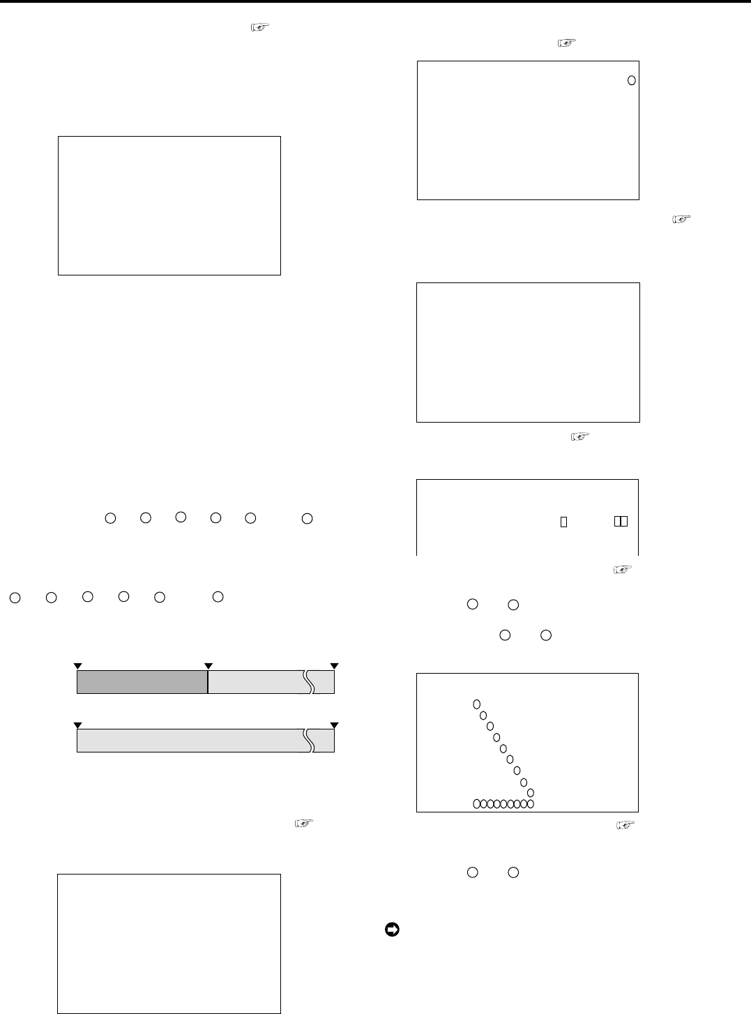
62
••••••••••••••••••••••••••••••••••••••••••••••••••••••••••••••••••••••••••••••••••••••••••••••••••••••••••••••••••••••••••••••••••••••••••••
Operation examples (continued)
3) Set each item in the <MOTION DETECTION SET-
TINGS> screen for all cameras ( see pages 39,40).
1
<MOTION DETECTION SETTINGS>
>>
SELECTION CAMERA NO.
DETECTION MASK SETTING
SENSITIVITY HIGH••<<<LOW
MOTION THRESHOLD 5
TEST MODE
4) <TIMER PROGRAM SETTINGS> screen setting (
see pages 44-46).
• SELECTED PATTERN : “P3”.
• ALARM REC DURATION : “5M”.
<TIMER PROGRAM SETTINGS>
SELECTED PATTERN P3-SET
HOLIDAY SETTING
REC MODE A
REC MODE B
REC MODE C
REC MODE D
>>
ALARM REC DURATION 5M
5) <REC MODE C> screen setting ( see page 46).
• MOTION DET REC : “ALARM”
• PRE ALARM REC : Set desired pre-alaem recording time.
<REC MODE C>
ALARM SETTING
RECORD SETTING
PRE ALARM REC ( S ) S
>>
MOTION DET REC ALARM
6) <ALARM SETTING C> screen setting ( see page
46).
• All cameras ( “
1
” ~ “
9
” ).
• TRIGGER : MD/EXT.
• EMR : All cameras ( “
1
” ~ “
9
” ) is setting.
<ALARM SETTING C> ALARM CH
ALARM RECORD CAMERA TRIGGER
1 -------- MD/EXT
2 - ------- MD/EXT
3 -- ------ MD/EXT
4 --- ----- MD/EXT
5 ---- ---- MD/EXT
6 ----- --- MD/EXT
7 ------ -- MD/EXT
8 ------- - MD/EXT
>>
9 -------- MD/EXT
EMR
9
7
456
1
23
8
<ALARM SETTING C>
9
7
456
1
23
8
7) <RECORD SETTING C> screen setting ( see page
46).
• Camera selection during alarm recording : “ALARM CH”.
• All cameras ( “
1
” ~ “
9
” ).
• PPS, GRADE, A-PPS, A-GRADE : Set desired interval
and picture quality for each camera.
When “0S” is selected, the pre-alarm recording
is inoperable.
7) <TIMER PROGRAM> screen setting ( see pages
44,45 ).
• PROGRAM NO.1 : “SPL”, “08:00”, “15:00”, “A”, “OFF”.
• PROGRAM NO.2 : “SPL”, “15:00”, “20:00”, “B”, “OFF”.
• PROGRAM NO.3 : “SAT”, “08:00”, “17:00”, “B”, “OFF”.
• PROGRAM NO.4 : “SUN”, “08:00”, “17:00”, “B”, “OFF”.
• PROGRAM NO.5 : “HOL”, “08:00”, “17:00”, “B”, “OFF”.
• SPL : “MON - FRI”.
<TIMER PROGRAM> P2
DW START END MODE MD
1
SPL 08:00
15:00 A OFF
2 SPL 15:00
20:00 B OFF
3
SAT 08:00 17:00 B OFF
4
SUN 08:00 17:00 B OFF
5
HOL 08:00 17:00 B OFF
6 --- --:-- --:-- ---- -
7 --- --:-- --:-- ---- -
8 --- --:-- --:-- ---- -
>>
SPL MON-FRI
When completed with all settings above and after clear-
ing the menu screen, press the TIMER button. The unit
will switch to the timer mode.
■ Operation example 3
This example illustrates the procedure for using Pre-alarm
recording, Alarm recording, Emergency recording with nor-
mal recording in Timer record mode.
< Operation >
• REC MODE C (pre-alarm recording, alarm recording and
emergency recording with all cameras) is set to Monday ~
Friday from 08:00 to 15:00 and REC MODE D (pre-alarm
recording, alarm recording and emergency recording with
camera number “
1
”, “
2
”, “
3
”, “
7
”, “
8
” and “
9
”) is
set to 15:00 ~ 08:00 of the following day.
• On weekends, REC MODE D (pre-alarm recording, alarm
recording and emergency recording with camera number
“
1
”, “
2
”, “
3
”, “
7
”, “
8
” and “
9
” ) is set to 08:00 ~
08:00 of the following day.
Next day
08:00
Next day
08:00
REC MODE C
REC MODE D
REC MODE D
From Monday
to Friday
Saturday and
Sunday
08:00
08:00 15:00
< Setting >
1) Set 1) ~ 3) of “Operation example “ 1 ” previous.
2) <REAR TERMINAL SETTINGS> screen setting ( see
page 51).
• EMERGENCY REC DURATION : “20M”.
<REAR TERMINAL SETTINGS>
MODE OUT 1 OFF
MODE OUT 2 OFF
MODE OUT 3 OFF
MODE OUT 4 OFF
MODE OUT 5 OFF
KEY SOUND ON
BUZZER OFF
REMAIN HDD MAIN-10
%
CALL OUT SETTINGS
>>
EMERGENCY REC DURATION 20M
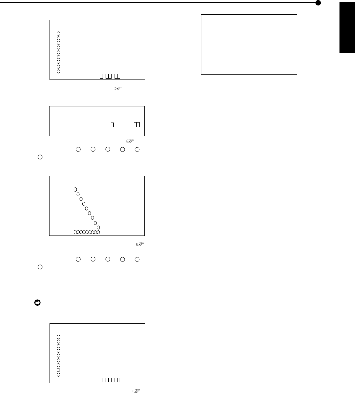
63
•••••••••••••••••••••••••••••••••••••••••••••••••••••••••••••••••••••••••••••••••••••••••••••••••••••••••••••••••••••••••••• Operations
ENGLISH
<TIMER PROGRAM> P3
DW START END MODE MD
1 SPL 08:00 15:00 C ON
2 SPL 15:00•08:00 D ON
3 SAT 08:00•08:00 D ON
4 SUN 08:00•08:00 D ON
5 --- --:-- --:-- ---- -
6 --- --:-- --:-- ---- -
7 --- --:-- --:-- ---- -
8 --- --:-- --:-- ---- -
>>
SPL MON-FRI
When completed with all settings above and after clear-
ing the menu screen, press the TIMER button. The unit
will switch to the timer mode.
<RECORD SETTING C>
9
7
4
5
6
1
2
3
8
<RECORD SETTING C> ALARM CH
NO PPS GRADE A-PPS A-GRADE
2.5P STD 2.5P HIGH
2.5P STD 2.5P HIGH
2.5P STD 2.5P HIGH
2.5P STD 2.5P HIGH
2.5P STD 2.5P HIGH
2.5P STD 2.5P HIGH
2.5P STD 2.5P HIGH
2.5P STD 2.5P HIGH
>>
2.5P STD 2.5P HIGH
<ESTD REC> D H M
8) <REC MODE D> screen setting ( see page 46).
• PRE ALARM REC : Set desired pre-alarm recording time.
• MOTION DET REC : “ALARM”
<REC MODE D>
ALARM SETTING
RECORD SETTING
PRE ALARM REC ( S ) S
>>
MOTION DET REC ALARM
9) <ALARM SETTING D> screen setting ( see page 46).
• Camera number “
1
”, “
2
”, “
3
”, “
7
”, “
8
” and
“
9
” only.
• TRIGGER : MD/EXT.
<ALARM SETTING D>
9
7
456
1
2
3
8
9
7
456
1
2
3
8
<ALARM SETTING D> ALARM CH
ALARM RECORD CAMERA TRIGGER
1 -------- MD/EXT
2 - ------- MD/EXT
3 -- ------ MD/EXT
4 --- ----- EXT
5 ---- ---- EXT
6 ----- --- EXT
7 ------ -- MD/EXT
8 ------- - MD/EXT
>>
9 -------- MD/EXT
EMR
10) <RECORD SETTING D> screen setting ( see page
46).
• Camera number “
1
”, “
2
”, “
3
”, “
7
”, “
8
” and
“
9
” only.
• PPS, GRADE, A-PPS, A-GRADE : Set desired interval
and picture quality for each camera.
• Other camera.
• PPS, A-PPS : “- - - - - -”.
When “0S” is selected, the pre-alarm recording
is inoperable.
<RECORD SETTING D>
9
7
4
5
6
1
2
3
8
<RECORD SETTING D> ALARM CH
NO PPS GRADE A-PPS A-GRADE
2.083P SUPER 4.165P HIGH
2.083P SUPER 4.165P HIGH
2.083P SUPER 4.165P HIGH
------ STD ------ STD
------ STD ------ STD
------ STD ------ STD
2.083P SUPER 4.165P HIGH
2.083P SUPER 4.165P HIGH
>>
2.083P SUPER 4.165P HIGH
<ESTD REC> D H M
11) <TIMER PROGRAM> screen setting ( see pages
44,45).
• PROGRAM NO.1 : “SPL”, “08:00”, “15:00”, “C”, “ON”.
• PROGRAM NO.2 : “SPL”, “15:00”, “08:00”, “D”, “ON”.
• PROGRAM NO.3 : “SAT”, “08:00”, “08:00”, “D”, “ON”.
• PROGRAM NO.4 : “SUN”, “08:00”, “08:00”, “D”, “ON”.
• SPL : “MON - FRI”.
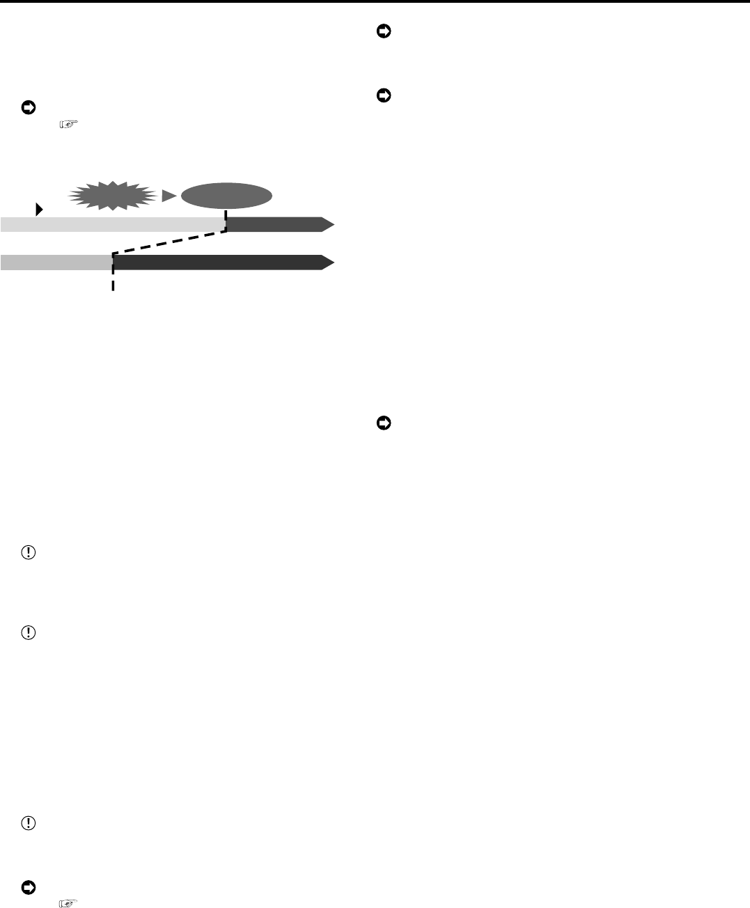
64
••••••••••••••••••••••••••••••••••••••••••••••••••••••••••••••••••••••••••••••••••••••••••••••••••••••••••••••••••••••••••••••••••••••••••••
■ PRE ALARM RECORDINGS
During alarm recording, recording can be started a few
seconds before the ALARM IN terminal is grounded or
motion is detected.
For details concerning pre-alarm recording set-
tings, see “Recording mode settings A ~ D for
normal recording/alarm recording” page 46.
Time
disturbance
Alarm input
Records data on HDD before alarm is input.
Camera input
Recording process
Pre-alarm recording :
1) A PRE ALARM indicator will be turned on if a “PRE
ALARM REC” setup is set up in addition to “0S.”
2) Starts recording video before the ALARM IN terminal is
ground or motion is detected.
3) Can only be executed when pre-alarm recording has
been set in the <RECORD SETTINGS> screen or <REC
MODE A> ~ <REC MODE D> screen. The recording chan-
nels after input of an alarm signals is executed only of cam-
era set in the <RECORD SETTINGS> screen and <REC
MODE A> ~ <REC MODE D> screen.
When a prealarm recording enters during nor-
mal recording, pre-alarm recording may be per-
formed for a time different from the time entered for
“PRE ALARM REC”.
When the alarm recording mode at the time of
prealarm recording is “ALARM CH”, prealarm
recording during normal recording is not possible
for all camera numbers set for alarm recording.
■ EMERGENCY RECORDINGS
If the EMERGENCY terminal is grounded when the MAIN
switch on the rear of the unit, and the POWER button on
the front of the unit are both ON and during timer record-
ing, EMERGENCY RECORDING will start automatically
overriding all other settings.
Emergency recording cannot be made when the
MAIN switch is OFF, the POWER button is OFF
and during timer recording stand-by.
For details concerning emergency recording set-
tings, see page 51.
Emergency recording :
1) Emergency recording is performed using all cameras
set to recording interval in “A-PPS” in the <RECORD SET-
TING> screen which cameras are selected in “EMR” in the
<ALARM SETTING> screen. For the record “SUPER” in
“A-GRADE” is selected and “A-PPS” is the minimum re-
cording interval which is selectable in each camera.
If a power outage occurs during emergency
recording, emergency recording is released after
power is restored.
If emergency recording is entered during timer
recording, recording is stopped at the timer record-
ing end time.
2) Cameras used
• Recording is performed with all cameras with “A-PPS”
on the <RECORD SETTING> screen set to other than
“- - - - - -” out of the camera numbers selected by “EMR”
on the <ALARM SETTING> screen.
• During timer recording, recording is performed using all
cameras other than those set to “- - - - - -” in the recording
mode of the set time frame.
3) During recording
• The EMERGENCY indicator flashes and then turns on
when recording is completed.
• The camera number buttons that are used for alarm re-
cording and the camera number display on the screen flash.
• The operation mode “ALARM” (in red) is displayed on the
screen.
To turn off the indicator, display the <ALARM LIST
SEARCH> screen and press the WARNING RESET
button for more than 5 seconds.
4) Recording is stored and displayed in the alarm list in
red.
Various recordings
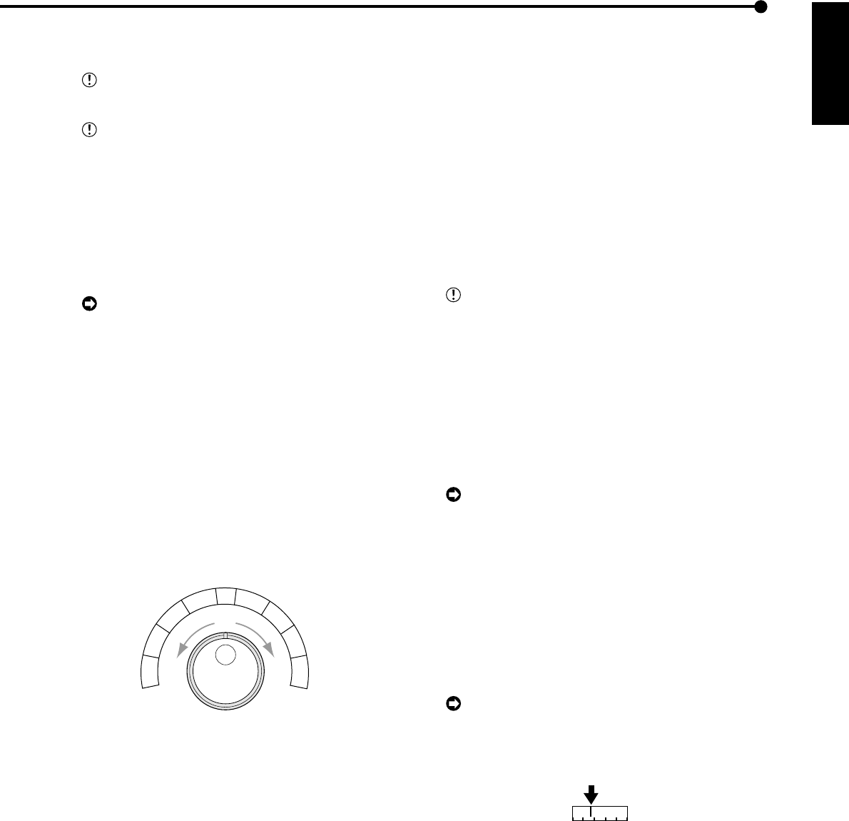
65
•••••••••••••••••••••••••••••••••••••••••••••••••••••••••••••••••••••••••••••••••••••••••••••••••••••••••••••••••••••••••••• Operations
ENGLISH
Various playback functions
Various playback functions that can be operated using the
JOG dial and SHUTTLE ring keys are featured on this unit.
If this unit is prompted to receive a live image
while playing back, this unit will end playback.
While this unit is being prompted to receive a live
image while transmitting, this unit cannot play back.
■ Playing still frames
1. Press the PAUSE button during playback.
• The unit switches to still frame playback. Press the button
again to resume playback.
• If a camera number (1 ~ 9) button is pressed during single
screen still frame playback, the video of the camera number
button pressed will be displayed by searching forward.
Image playback displays only one picture. Press
the camera button to perform search. When a
camera number without a recorded image or few
recorded images is specified, search may continue
for hours. If it is unnecessary, press the SEARCH
button to release search status.
■ Shuttle viewing/direct shuttle viewing
Turning the SHUTTLE ring during still frame playback, play-
back or reverse playback, the playback speed can be
changed.
1. (During shuttle viewing • • • )
Turn the SHUTTLE ring during still frame playback.
• The playback speed depends on the angle the SHUTTLE
ring is turned.
• When letting go of the SHUTTLE ring, the ring will return to
the center and the unit will return to still frame playback.
2
3
456
7
8
1 High-speed rewind (1GB units)
2 Reverse speed search (100MB units)
3 Reverse speed search (10MB units)
4 Reverse speed search (1MB units)
5 Still frame playback
6 Forward speed search (1MB units)
7 Forward speed search (10MB units)
8 Forward speed search (100MB units)
9 High-speed fast forward (1GB units)
19
2. (During direct shuttle viewing • • • )
Turn the SHUTTLE ring during playback or reverse playback.
• The playback speed depends on the angle the SHUTTLE
ring is turned.
• When letting go of the SHUTTLE ring, the ring will return to
the center and the unit will return to still frame playback. (The
unit will not return to playback or reverse playback.)
■ Shuttle hold
The playback speed can be maintained even when letting
go of the SHUTTLE ring during shuttle viewing.
1. Press the PAUSE (SHUTTLE HOLD) button while holding
the SHUTTLE ring in angle during shuttle playback.
2. Let go of the SHUTTLE ring.
• The playback speed is maintained.
• To cancel shuttle hold, press the PAUSE button. The unit
will switch to still frame playback.
■ Frame-by-frame playback
1. Turn the JOG dial during still frame playback.
• Clockwise : Forward frame feeding.
• Counterclockwise : Reverse frame feeding.
• Clockwise and hold : Continuous forward frame feeding.
• Counterclockwise and hold : Continuous reverse frame
feeding.
• When turning of JOG dial is stopped : Unit returns to still
frame playback.
During frame feeding in the single screen mode,
the frame feeding operation may not operate cor-
rectly when the JOG dial is turned too fast since
frame feeding is performed while searching the video
of the display camera number.
■ Reverse playback
1. Press the REV. PLAY (REVERSE PLAYBACK) button while
playback is stopped.
• Playback will be made in the reverse direction. Playback
will stop when press the STOP button.
When reverse playback is performed first after
turning the power on, the last recorded video will be
played back in reverse first.
■ High-speed fast-forward/high-speed rewind
1. Turn the SHUTTLE ring for more than 1 second while
playback is stopped.
• Clockwise for more than 1 second :
Will activate High-speed fast-forward playback (1GB units).
• Counterclockwise for more than 1 second :
Will activate High-speed rewind playback (1GB units).
• Press the STOP button: Playback is stopped.
During high-speed fast-forward/rewind, the current
position is displayed on the bottom or top of the screen.
S (start) and E (end) indicate the beginning and end of
the HDD space and “I” indicates the current position.
SE
current position
■ Changing playback intervals
Although, playback and reverse playback use the same
interval as that for recording, it is possible to change the
playback interval. This function is useful for slow-motion
playback of fast-moving footage, or quick playback of ex-
tensive footage without skipping frames.
1-1. (To play back recording with fast motion slowly • • • )
Press the REV. PLAY (REVERSE PLAYBACK) button during
playback or reverse playback.
• Playback or reverse playback will be made at 0.125P intervals
per camera.

66
••••••••••••••••••••••••••••••••••••••••••••••••••••••••••••••••••••••••••••••••••••••••••••••••••••••••••••••••••••••••••••••••••••••••••••
Various playback functions (continued)
1-2. Press the PLAY button.
• The playback interval is changed to a faster setting (0.25P,
0.5P, and so on) each time the button is pressed.
2-1. (To play back video recorded using extended recording
intervals fast • • • )
Press the PLAY button during playback or reverse playback.
• Playback or reverse playback will be made at 50P intervals
per camera.
2-2. Press the REV. PLAY (REVERSE PLAYBACK) button.
• The playback interval is changed to a slower setting (25P,
12.5P, and so on) each time the button is pressed.
Audio cannot be played back when changing the
playback interval.
Once the playback interval is changed, audio
will not be played back even when returning the play-
back interval to the original value. To playback au-
dio, pause playback and then play the video again.
Once the playback interval is changed, the green
display of the playback interval will remain un-
changed even when returning the playback interval
to the original value. To check the original playback
interval of the recording, pause playback and then
play the video again.
Altering the playback interval settings and then
performing a quick playback of data with long re-
cording time may cause discrepancies between ac-
tual recording time and the recording time displayed
on the screen.
When changing to the single display mode with
“2” or “3” set in “DISPLAY MODE” in the <TIME
DATE /DISPLAY SETTINGS> screen, the play-
back interval is displayed on the screen in green
for easy confirmation if the value is changed.
■ Simultaneous playback during recording
The recorded data can be played back simultaneously
during the unit is recording.
The video being played back may pause tempo-
rarily or the sound may be interrupted.
Noise may be noticeable on the video during
shuttle playback.
Split screen display can be selected individually
for recording/playback.

67
•••••••••••••••••••••••••••••••••••••••••••••••••••••••••••••••••••••••••••••••••••••••••••••••••••••••••••••••••••••••••••• Operations
ENGLISH
Various search
The various search functions of this unit can be used to
skip to the beginning of the desired video.
If this unit is prompted to receive live images while
search is set, this unit will not move to perform
search. In addition, if prompted to receive live images
while searching, this unit will forcibly stop search.
This unit cannot search while being prompted to
receive live images.
Image playback displays only one picture. Press the
camera button to perform search. When a camera number
without a recorded image or few recorded images is
specified, search may continue for hours. If it is unnecessary,
press the SEARCH button to release search status.
■ SEARCH SELECTION
The search screen appears when the SEARCH button on this
unit is pressed. When pressing the SEARCH button again, the
<SEARCH SELECTION> screen appears to select the playback
device, search type and the camera number to search.
♦ SEARCH TYPE
When pressing the SEARCH button, which search screen
to display from the 5 search functions is set.
<SEARCH SELECTION>
>>
SEARCH TYPE TIME DATE
SELECTION CAMERA NUMBER ALL
PLAYBACK DEVICE MAIN
MAIN
START 02-02-2004 00:00:00
END 04-04-2004 12:30:15
Setting ( default : “TIME DATE” )
“TIME DATE”, “INDEX”, “ALARM INDEX”,
“ALARM SKIP”, “ALARM LIST”
1. Press the SEARCH button twice.
• The search screen appears when the button is pressed the
first time. The <SEARCH SELECTION> screen appears when
the button is pressed again.
2. Display the desired setting in “SEARCH TYPE” and confirm.
3. Turn the SHUTTLE ring counterclockwise.
• The search screen set in step 2 appears.
4. Turn the SHUTTLE ring counterclockwise or press the
SEARCH button.
♦ SELECTION CAMERA NUMBER
The camera number to search is selected. “SELECTION
CAMERA NUMBER” setting will not appear if “SEARCH
TYPE” is set to “INDEX SEARCH”.
<SEARCH SELECTION>
SEARCH TYPE TIME DATE
>>
SELECTION CAMERA NUMBER ALL
PLAYBACK DEVICE MAIN
MAIN
START 02-02-2004 00:00:00
END 04-04-2004 12:30:15
Setting ( default : “ALL” )
“ALL”, “
1
”, “
2
”, “
3
”, “
4
”, “
5
”, “
6
”, “
7
”,
“
8
”, “
9
”
“ALL” : Searches all camera numbers (“
1
” ~ “
9
”)
and displays all images on a 9 split-screen.
“
1
” ~ “
9
” : Searches selected camera numbers,
and displays on 1 screen the image that best
matches specified criteria.
1. Press the SEARCH button twice to display the <SEARCH
SELECTION> screen.
2. Display the desired setting in “SELECTION CAMERA
NUMBER” and confirm.
3. Turn the SHUTTLE ring counterclockwise.
• The display returns to the search screen.
4. Turn the SHUTTLE ring counterclockwise or press the
SEARCH button.
♦ DATE/TIME
Displayed only when the previous “SEARCH TYPE” is
set to “ALARM LIST”. Used when narrowing down the
number of lists to display on the screen during alarm
list search ( see pages 70,71 ).
♦ PLAYBACK DEVICE
Select the HDD to play back.
<SEARCH SELECTION>
SEARCH TYPE TIME DATE
SELECTION CAMERA NUMBER ALL
>>
PLAYBACK DEVICE MAIN
MAIN
START 02-02-2004 00:00:00
END 04-04-2004 12:30:15
Setting ( default : “MAIN” )
“MAIN”, “SUB”, “CFC”
“SUB” is appeared on the screen when
“PARTITION” is selected on “HDD SETTING” of the
<INITIALIZATION> screen.
1. Press the SEARCH button twice to display the <SEARCH
SELECTION> screen.
2. Display the desired setting in “PLAYBACK DEVICE” and
confirm.
3. Turn the SHUTTLE ring counterclockwise.
• The display returns to the search screen.
4. Turn the SHUTTLE ring counterclockwise or press the
SEARCH button.
START/END display
The date/time of the recording start/end points of
the device set in “PLAYBACK DEVICE” is displayed.
Use this as reference when searching.
■ TIME DATE SEARCH
See pages 24,25.
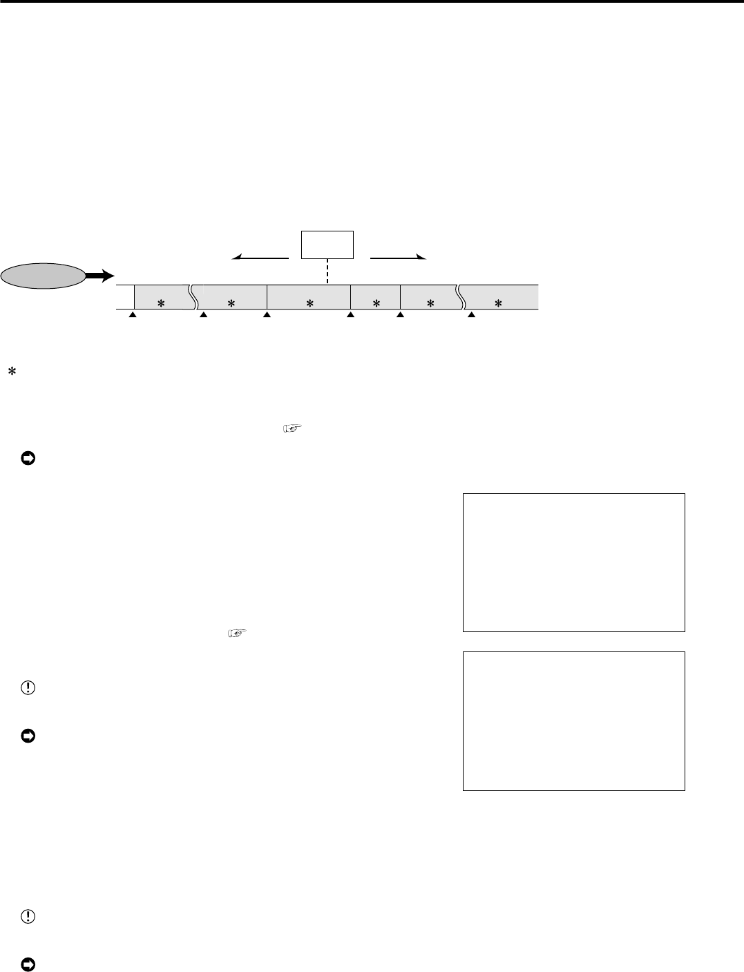
68
••••••••••••••••••••••••••••••••••••••••••••••••••••••••••••••••••••••••••••••••••••••••••••••••••••••••••••••••••••••••••••••••••••••••••••
Various search (continued)
<ALARM INDEX SEARCH>
>>
INDEX 01
EXECUTE(FORWARD)
EXECUTE(REVERSE)
MAIN
START 02-02-2004 00:00:00
END 04-04-2004 12:30:15
PUSH SEARCH KEY FOR
SEARCH SELECTION
<INDEX SEARCH>
>>
INDEX 01
EXECUTE(FORWARD)
EXECUTE(REVERSE)
MAIN
START 02-02-2004 00:00:00
END 04-04-2004 12:30:15
PUSH SEARCH KEY FOR
SEARCH SELECTOIN
■ INDEX SEARCH/ALARM INDEX SEARCH
With this unit, index signals are automatically written to the HDD at the start
of each recording. It is possible to search these signals and playback start-
ing at such index points.
There are 2 types of index searches :
• <INDEX SEARCH> : Searches index signals written when starts recording.
• <ALARM INDEX SEARCH> : Searches index signals written when starts
alarm recording and emergency recording.
Up to 99 indexes can be searched in either forward/reverse direction.
How indexes are counted for <INDEX SEARCH>, <ALARM INDEX
SEARCH>
INDEX COUNT
99 02 01 99
02
01
RecordingRecording RecordingRecording Recording Recording
Index
signal Index
signal
Index
signal Index
signal Index
signal Index
signal
Forward
Reverse
Present
position
( ) ( ) ( ) ( ) ( ) ( )
( ) : Normal recording for INDEX SEARCH. Alarm recording or emergency
recording for ALARM INDEX SEARCH.
1. Press the SEARCH button.
• The search screen selected in the “SEARCH TYPE” ( see page 67) appears.
“SELECTION CAMERA NUMBER” setting will not appear if “IN-
DEX SEARCH” is set.
2. (When the desired search screen is not displayed on the screen • • • )
Change the previous “SEARCH TYPE” setting and display the “INDEX SEARCH”
screen or “ALARM INDEX SEARCH” screen.
• When searching index signals of normal recording, display the “INDEX SEARCH”
screen.
• When searching index signals of alarm recording or emergency recording,
display the “ALARM INDEX SEARCH” screen.
• After performing INDEX SEARCH/ALARM INDEX SEARCH :
• SPLIT9 screen is always displayed for INDEX SEARCH.
• For ALARM INDEX SEARCH, SPLIT9 screen is displayed when setting the
“SELECTION CAMERA NUMBER” ( see page 67) to “ALL”. Single
screen with still frame playback is displayed when selecting individual
camera number.
When execute “ALARM INDEX SEARCH” while the “PARTITION”
is set, set to “SUB” in “PLAYBACK DEVICE”.
The camera number written by the start index signal of the pre-
alarm recording may differ from the camera number displayed in the
alarm list.
3. Display the desired setting in “INDEX” and confirm.
4. Select “EXECUTE(FORWARD)” or “EXECUTE(REVERSE)” and confirm.
• “EXECUTE (FORWARD)” : Search is performed in the forward direction.
• “EXECUTE (REVERSE)” : Search is performed in the reverse direction.
• To cancel the search, press the SEARCH button twice.
• Search will not be performed if there are no index signals. To return to the normal
screen, press the SEARCH button twice.
Search may take time, depending on the recording status of the
index signal. Press the STOP button while searching to end search.
If the intervals of the index are long, search may continue for
hours.
5. Playback the search result.
• Press the PLAY (REV. PLAY) or PAUSE button.
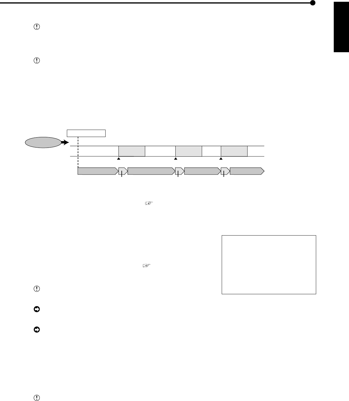
69
•••••••••••••••••••••••••••••••••••••••••••••••••••••••••••••••••••••••••••••••••••••••••••••••••••••••••••••••••••••••••••• Operations
ENGLISH
<ALARM SKIP SEARCH>
>>
EXECUTE(FORWARD)
EXECUTE(REVERSE)
PUSH SEARCH KEY FOR
SEARCH SELECTION
6. To stop playback or still-frame playback, press the STOP button.
To change the desired camera number to the single screen dis-
play during still-frame playback in SPLIT9 display, press the SEARCH
button to clear the search setting screen and press the desired cam-
era number button.
Search may not perform properly at times depending on the re-
corded condition of the index signals.
7. To clear the search screen, press the SEARCH button twice.
■ ALARM SKIP SEARCH
This function searches up to where the Alarm recording signal is located,
and can playback at 4 second intervals.
<ALARM SKIP SEARCH> In the case of forward direction
SKIP COUNT
0302
01
Alarm
Recording Alarm
Recording Alarm
Recording
Index signalIndex signalIndex signal
Search SearchSearch Search
Present position
Approx. 4 sec.
play Approx. 4 sec.
play Approx. 4 sec.
play
1. Press the SEARCH button.
• The search screen selected in the “SEARCH TYPE” ( see page 67) appears.
2. (When the desired search screen is not displayed on the screen • • • )
Change the previous “SEARCH TYPE” setting and display the “ALARM SKIP
SEARCH” screen.
3. Select “EXECUTE(FORWARD)” or “EXECUTE(REVERSE)” and confirm.
• “EXECUTE(FORWARD)” : Search is performed in the forward direction.
• “EXECUTE(REVERSE)” : Search is performed in the reverse direction.
• To cancel the search, press the SEARCH button twice.
• Playback of search result from skip search will be in SPLIT9 display regardless
of whether the “SELECTION CAMERA NUMBER” ( see page 67) is set to
“ALL” or individual camera number is selected.
• To return to the normal screen, press the SEARCH button twice.
When execute “ALARM SKIP SEARCH” while the “PARTITION”
is set, set to “SUB” in “PLAYBACK DEVICE”.
Search may take time, depending on the recording status of the
index signal. Press the STOP button while searching to end search.
Press the desired camera number button when performing skip
search in SPLIT9 display, the video of the camera number button is
changed to single screen display.
4. Press the PAUSE button when the desired video is displayed and press the
PLAY button.
5. To stop ALARM SKIP SEARCH, press the STOP button.
6. To clear the search screen, press the SEARCH button twice.
When performing skip search in the reverse direction with index
signals of less than 4 seconds, that portion may play back repeat-
edly. In this case, press the STOP button to stop the search and
perform skip search in the reverse direction again after the particular
portion has been passed using reverse playback, etc.
70
••••••••••••••••••••••••••••••••••••••••••••••••••••••••••••••••••••••••••••••••••••••••••••••••••••••••••••••••••••••••••••••••••••••••••••
Various search (continued)
Search may not perform properly at times de-
pending on the recorded condition of the index
signals.
Search may take time, depending on the
recording status of the index signal. Press the STOP
button while searching to end search.
6. To clear the search screen, press the SEARCH button twice.
■ ALARM LIST SEARCH
This unit stores the start time of alarm recording and emer-
gency recording in the alarm list when such recording be-
gins. It is also possible to index search the desired time (or
the closest time) from the list of alarm recording (emer-
gency recording) start times stored in the alarm list.
To clear the alarm list, erase the data in the
<MAIN HDD DATA CLEAR> (<SUB HDD DATA
CLEAR>) screen. Beware that executing it erases
all the data of HDD contained the video data. Alarm
recording then will be stored again from 00001.
Up to 10,000 alarm recording (emergency re-
cording) start times can be stored and displayed.
In the alarm list, items with the ALARM IN termi-
nal on the rear grounded are indicated in white, items
that were detected with motion are indicated in green
and items with the EMERGENCY terminal grounded
are indicated in red.
1. Press the SEARCH button.
• The search screen selected in the “SEARCH TYPE” (
see page 67) appears.
<SEARCH SELECTION>
>>
SEARCH TYPE ALARM LIST
SELECTION CAMERA NUMBER ALL
DATE/TIME - - : :
PLAYBACK DEVICE SUB
SUB
START 02-02-2004 00:00:00
END 04-04-2004 12:30:15
The Alarm list may take time to display completely
when there are many list items or the HDD has been
expanded.
2. (When the desired search screen is not displayed on the
screen • • • )
Change the previous “SEARCH TYPE” setting and display the
“ALARM LIST SEARCH” screen.
To display the emergency recording start time in
the alarm list, set “SELECTION CAMERA NUMBER”
in the <SEARCH SELECTION> screen to “ALL”.
“EMR” indicating emergency recording will appear
in the place of the camera number in the alarm list.
<ALARM LIST SEARCH>
>>
00004 01-01-2004 00:00:04 1
00003 01-01-2004 00:00:03 EMR
00002 01-01-2004 00:00:02 1
00001 01-01-2004 00:00:01 EMR
PUSH SEARCH KEY
1
2
Recorded camera
Camera of alarm input
“Camera of alarm input” displays the camera
number which is input alarm signals, and “record
camera” displays the camera number which started
recording.
When the correspondent cameras for alarm sig-
nals are not set for the recording, the record is
storaged using the camera of the youngest number.
When execute “ALARM LIST SEARCH” while
the “PARTITION” is set, set to “SUB” in “PLAYBACK
DEVICE”.
If motion is detected and the ALARM IN terminal
on the back is grounded at the same time, all of
those start times may not be registered to the alarm
list. In such cases, the smallest numbered camera
is registered to the camera list.
4. Select the desired alarm list number and turn the
SHUTTLE ring clockwise to confirm.
• button/turn JOG dial counterclockwise : Selection moves
to the next number.
• button/turn JOG dial clockwise : Selection moves to the
previous number.
• button : Displays the page with date prior to the date of
the currently opened page.
• button : Displays the page with date newer than the date
of the currently opened page.
• To cancel search, press the SEARCH button twice.
• After performing alarm search, the screen will be in the single
screen display with still-frame playback regardless of whether
setting “ALL” in the “SELECTION CAMERA NUMBER” (
see page 67) or selecting an individual camera number.
The camera number written by the start index
signal of the pre-alarm recording may differ from the
camera number displayed in the alarm list.
When setting “HDD REPEAT REC MAIN” to
“OFF” or “STANDBY”, “HDD REPEAT REC SUB” to
“OFF” and there is an alarm recording (emergency
recording) at the end of the HDD, that recording may
not be stored in the alarm list and that number may
become missing and not displayed.
When an alarm recording (emergency record-
ing) is performed during using display of the
<ALARM LIST SEARCH> screen, exit the <ALARM
LIST SEARCH> screen and display the screen
again. The new item will be added to the list.

71
•••••••••••••••••••••••••••••••••••••••••••••••••••••••••••••••••••••••••••••••••••••••••••••••••••••••••••••••••••••••••••• Operations
ENGLISH
When using “DATE/TIME” in the <SEARCH SE-
LECTION> screen, the number of list items displayed
on the screen can be narrowed down.
1. Press the SEARCH button to display the <SEARCH
SELECTION> screen.
2. Set the desired date and time of the result in “DATE/
TIME” and confirm.
3. Turn the SHUTTLE ring counterclockwise once to
display narrowed-down list.
4. Playback the search result.
• Press either the PLAY (REV. PLAY) or PAUSE button.
5. To stop playback or still-frame playback, press the STOP
button.
6. To clear the search screen, press the SEARCH button twice.
■ START/END SEARCH
It is possible to search the recording starting/ending point
of the device (media) selected by “PLAYBACK DEVICE” in
<TIMER DATE SEARCH>, <INDEX SEARCH> and
<ALARM INDEX SEARCH> for playback.
1. Press the SEARCH button.
• The search screen selected in previous “SEARCH TYPE”
appears.
2-1. (To play back the oldest recording • • • )
Select “START” and turn the SHUTTLE ring clockwise.
2-2. (To play back the last recording • • • )
Select “END” and turn the SHUTTLE ring clockwise.
3. Playback the search result.
• Press the PLAY (REV. PLAY) or PAUSE button.
4. To stop playback or still-frame playback, press the STOP
button.
To change the SPLIT9 screen during still-frame
playback to single screen display of the desired cam-
era number, press the SEARCH button to clear the
search mode screen and press the desired camera
number button.
5. To clear the search screen, press the SEARCH button twice.

72
••••••••••••••••••••••••••••••••••••••••••••••••••••••••••••••••••••••••••••••••••••••••••••••••••••••••••••••••••••••••••••••••••••••••••••
Making Copy/Restore
■ Making Copy/Restore
Data in MAIN HDD or SUB HDD can be copied to Compact
Flash Card. Data in Compact Flash Cards can be restored
to MAIN HDD.
Setting
“MAIN HDD } CFC” : The data recorded on MAIN
HDD is copied to Compact Flash Card.
“SUB HDD } CFC” : The data recorded on SUB
HDD is copied to Compact Flash Card.
“CFC } MAIN HDD” : The data recorded on Com-
pact Flash Card is restored to MAIN HDD.
“SUB HDD } CFC” is appeared when “PARTI-
TION” is selected on “HDD SETTING” of the <INI-
TIALIZATION> screen.
Before use, read the cautionary notes described
in the manual included with Compact Flash Card.
1-1. (To copy to a Compact Flash Card • • • )
Insert the Compact Flash Card into the COMPACT FLASH
slot of this unit.
1-2. Press the COPY button.
• The <COPY> screen appears.
1-3. Display “MAIN HDD
}
CFC” (“SUB HDD
}
CFC”
)
on
“DIRECTION” and confirm.
<COPY>
>>
DIRECTION MAIN HDD}CFC
MODE OVERWRITE
TRANSFER PERIOD START•END
START 01-01-2004 00:00:00
END 01-01-2004 00:00:10
EXECUTE
2-1. (To restore data from or Compact Flash Card • • • )
Press the COPY button.
• The COPY screen is displayed.
2-2. Display the desired setting “CFC
}
MAIN HDD” on
“DIRECTION” and confirm.
<RESTORE>
>>
DIRECTION CFC}MAIN HDD
MODE OVERWRITE
TRANSFER PERIOD START•END
START 01-01-2004 00:00:00
END 01-01-2004 00:00:10
EXECUTE
The menu changes to <RESTORE> when “CFC
} MAIN HDD” is selected.
The warning display at the time of RESTORE
execution displays “RESTORE/XXX” when the <RE-
STORE> screen is displayed and “REST/XXX” when
the normal screen is displayed.
3. Display the desired setting in “MODE” and confirm.
Setting ( default : “OVERWRITE” )
“OVERWRITE” : Overwrites current data.
“NO OVERWRITE” : Writes following last entry.
When “DIRECTION”, and “OVERWRITE” on
“MODE”, all data on the Compact Flash Card re-
gardless of menu division is overwritten.
4. Display the desired setting in “TRANSFER PERIOD” and
confirm.
Setting ( default : “START•END” )
“START•END” : Sets the recording start/end date/
time.
“START” : Sets the recording start date/time.
“LATEST DATA” : Starts copying from the end point
according to the available memory in the COPY de-
vice.
5. Set the desired copy (restore) start date and time to “START”
and confirm.
6. (When setting “START•END” in step 4 • • • )
Set the desired copy (restore) end date and time to “END”
and confirm.
7. Select “EXECUTE” and turn the SHUTTLE ring clockwise.
• The copy (restore) operation is executed.
• If the copy (restore) operation does not start, turn the
SHUTTLE ring counterclockwise or press the COPY button.
The “COPY/NO MEDIA” or “REST/NO MEDIA”
warning is displayed when executing COPY or
RESTORE without a Compact Flash Card inserted
in the slot.
If the copy range exceeds the available ca-
pacity of the Compact Flash Card, “COPY/SIZE/
DATA ERROR” warning will appear on the screen
when copying ( see pages 87,88). In this case,
set again using narrower copy range or insert a
Card larger capacity.
If a data with no date is included in the copy
range, “COPY/SIZE/DATA ERROR” warning will ap-
pear on the screen.
When there is no data to restore in the Compact
Flash Card “REST/SIZE/DATA ERROR” warning will
appear on the screen when restoring.
A “REST/MEDIA ERROR” error is displayed
when executing RESTORE from a non-FSM2 Com-
pact Flash Card.
For usable Compact Flash Card, check with your
dealer of purchase.
When copy is performed during record, an im-
age may not be recorded at the time of a copy start
and an end. Be careful.
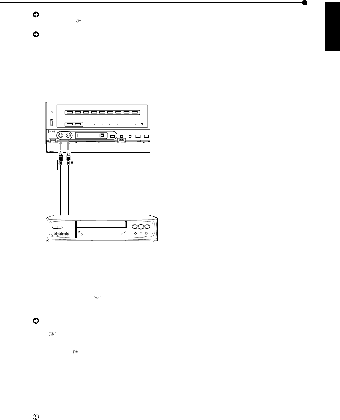
73
•••••••••••••••••••••••••••••••••••••••••••••••••••••••••••••••••••••••••••••••••••••••••••••••••••••••••••••••••••••••••••• Operations
ENGLISH
For the recordable time when copying to a Com-
pact Flash Card, see page 84.
This image data is administrated in 1MB unit.
Therefore, the copied area may be larger than the
set area because copying is performed in 1MB units
that include the specify area.
■ Copying from unit to videotape
Data can be copied even when the unit is recording. For
recording operations, see the instruction manual accom-
panying the analog video cassette recorder.
AUDIO CORD
(commercially
available cable,
if necessary)
To AUDIO OUT
terminal
To VIDEO OUT
terminal
VIDEO CORD
(commercially
available cable)
To AUDIO IN
terminal
To VIDEO IN
terminal
ANALOGUE VIDEO CASSETTE RECORDER
1. [Analogue video cassette recorder] Prepare the unit for
recording.
• First, set the input source to the external input connecting
this unit.
2. [This unit] Press the SPLIT/SEQUENCE button to select
the screen type to play back ( see page 36).
• Single screen, SPLIT4 (a, b and c) screen and SPLIT9 screen
can be selected.
It is also possible to copy the video of each cam-
era in order using single screen sequential play-
back ( see “SEQUENTIAL PLAY”, page 48).
3. [This unit] Use the search function to move to the beginning
of the video to copy ( see “START/END SEARCH”, page
71).
4. [Analogue video cassette recorder] Start recording.
5. [This unit] Press the PLAY button to start playback.
6. To stop copying, press the STOP button of this unit. After
stopping playback, stop the recording on the analogue video
cassette recorder.
Only video recorded of camera number dis-
played on the screen can be copied to videotape.

••••••••••••••••••••••••••••••••••••••••••••••••••••••••••••••••••••••••••••••••••••••••••••••••••••••••••••••••••••••••••••••••••••••••••••
74
■ Power failure compensation circuit
The unit is equipped with an internalized power failure com-
pensation circuit. When the unit has been charged for 48
hours (full), the date, time, timer record settings, and menu
settings are kept up to 1 month without power. The accu-
racy of the time will decline if the power plug is not con-
nected to the wall outlet for and extensive period. In this
case, it is recommended to check the current time setting.
■ Power failure reset recording
If there is a power failure during recording or when turning
OFF the MAIN switch, the recording will resume after the
power is restored. If there is a power failure during timer
recording, the recording will resume after the power is re-
stored when within the set time period of the timer. For alarm
recording, recording will stop even within the set recording
time.
If there is a power outage while recording, video
and audio of up to 6MB from immediately before the
power outage will not be recorded.
If there is a power outage while alarm recording or
emergency recording, alarm recording and emergency
recording will be released after power is restored.
When recording is started, “REC ON” is registered
in <WARNING LOG LIST>. However, “REC ON” will
not be registered when recording is resumed after
power is restored.
The playback video at the start position where re-
cording is resumed after a power failure may be dis-
turbed and the search function may not operate prop-
erly.
■ Log function for when power failure occurs
while the unit is in operation or the MAIN
switch on the rear of the unit is turned OFF
In the event of power failure or the MAIN switch on the
rear of the unit is turned OFF, up to 1000 items (includ-
ing the time of failure and warning log displays as well
as other warning items) are saved in the <WARNING
LOG LIST> ( see pages 54,55), and are displayed
in red on the screen.
For power outages that occur while timer recording
is standing by, “P-LOSS” that indicates a power outage
is not displayed. In addition, power outages that overlap
with timer recording start times and those where power
is restored after the recording end time are also not
recorded.
■ RESET button
When pressing the RESET button on the rear of the unit
with a ballpoint pen, etc., the unit is reset and the power
turns off.
The menu settings, the current time and video data
are kept even when resetting the unit.
■ HDD SETTING
On the unit, “MIRRORING” and “PARTITION” can be se-
lected for the HDD recording mode ( see page 18).
Setting ( default : “NORMAL” )
“NORMAL”, “MIRRORING”, “PARTITION”
♦ MIRRORING
By saving the data in duplicate on two HDD’s with the
same capacity, the risk of data loss due to an HDD crash
is greatly reduced.
When using a MIRRORING function, two sets of
HDD are required. It does not function in one HDD.
Please consult with the retailer, when you add HDD.
1. Turn ON the MAIN switch on the rear of the unit, and wait
until the ACCESS indicator goes off. Hold down the REC/STOP
button, and press the POWER button on the front of the unit.
• The <INITIALIZATION> screen is displayed.
<INITIALIZATION>
>>
HDD SETTING NORMAL
POWER OFF
INITIALIZATION
ALL DATA WILL BE ERASED
WHEN PROCEED INITIALIZATION
POWER button operation will not be accepted while
the ACCESS indicator is flashing. Press the POWER
button after the indicator turns off.
2. Select “HDD SETTING” by turning the JOG dial, display the
“MIRRORING” setting, and turn the SHUTTLE ring clockwise.
<INITIALIZATION>
>>
HDD SETTING MIRRORING
POWER OFF
INITIALIZATION
ALL DATA WILL BE ERASED
WHEN PROCEED INITIALIZATION
3. Select “INITIALIZATION” by turning the JOG dial, and turn
the SHUTTLE ring clockwise.
• The setting is made, and initialization commences.
Settings are not confirmed unless you perform
“INITIALIZATION”.
Initialization deletes all data in the HDD.
Other convenient functions

75
ENGLISH
•••••••••••••••••••••••••••••••••••••••••••••••••••••••••••••••••••••••••••••••••••••••••••••••••••••••••••••••••••••••••••• Operations
Points to be aware of regarding MIRROR mode
• Performing RESTORE restores identical data to
both HDD master and HDD slave.
• Performing “MAIN HDD DATA CLEAR” in “MIR-
RORING” mode deletes all data in both HDD.
• In the event of a HDD master/HDD slave malfunc-
tion, HDD master/HDD slave items are registered
separately on the <WARNING LOG LIST>.
• In the event that either HDD maste or HDD slave
malfunction, the “MIRROR” warning is displayed,
and the operable HDD continues the recording.
Press the WARNING RESET button on the front
of the unit to reset the “MIRROR” warning.
• The “MIRROR” warning is displayed every time
the unit is started-up until the faulty HDD is re-
placed.
• Automatic data archive commences at start-up
after replacement with an operational HDD.
• If any HDD of each HDD master and HDD slave
malfunction simultaneously, the data can not be
repaired.
• Ask at place of purchase about data restoration
when repairing/replacing a faulty HDD.
Points to be aware of regarding PARTITION
mode
• Either “MAIN” or “SUB” can be selected for copy.
• Playback, search, information display, REMAIN
HDD, CALL OUT, and data delete functions are
performed independently for “MAIN” and “SUB”.
• When “HDD REPEAT REC SUB” is set to “OFF”,
and all memory in SUB HDD is used, the record-
ing stops. Afterwards, the indicator will blink when
an alarm enters, but no recording will be
performed.
• When at the time of “ALARM CH” use an alarm
signal enters to a camera number not set for nor-
mal recording, pre-alarm recording may not be
performed in some cases.
♦ PARTITION/PARTITION SIZE
PARTITION mode only uses the internal HDD.
PARTITION mode designates the area inside the HDD
that is specified as each HDD’s sub-device capacity for
Alarm recording. This independent partition inside the
HDD allows to keep the data of alarm recording.
The normal recording area is referred to as “MAIN”,
and the alarm recording area (PARTITION area) is re-
ferred to as “SUB”.
1. Turn ON the MAIN switch on the rear of the unit, and wait
until the ACCESS indicator goes off. Hold down the REC/STOP
button, and press the POWER button on the front of the unit.
• The <INITIALIZATION> screen is displayed.
POWER button operation will not be accepted while
the ACCESS indicator is flashing. Press the POWER
button after the indicator turns off.
2. Select “HDD SETTING” by turning the JOG dial, display
“PARTITION”, and turn the SHUTTLE ring clockwise.
• The “PARTITION SIZE” setting appears on the
<INITIALIZATION> screen.
<INITIALIZATION>
>>
HDD SETTING PARTITION
PARTITION SIZE 10
%
POWER OFF
INITIALIZATION
ALL DATA WILL BE ERASED
WHEN PROCEED INITIALIZATION
3. Display the desired device capacity, and turn the SHUTTLE
ring clockwise.
• The setting is made.
• Setting of “PARTITION SIZE” ( default : 10% )
10%, 20%, 30%, 40%, 50%, 60%, 70%, 80%, 90%
The storage area in MAIN HDD set in “PARTITION”
is displayed with the percentage(%) and the record-
able time of that storage area is displayed in “<ESTD
REC>”.
2
.
5P
STD
2
.
5P
STD
2.5P STD 2.5P STD
2.5P STD 2.5P STD
<ESTD REC> D H M %
9
7
8
4. Select “INITIALIZATION” by turning the JOG dial, and turn
the SHUTTLE ring clockwise.
• The setting is made, and initialization commences.
Settings are not confirmed unless you perform
“INITIALIZATION”.
Initialization deletes all data in the HDD.

••••••••••••••••••••••••••••••••••••••••••••••••••••••••••••••••••••••••••••••••••••••••••••••••••••••••••••••••••••••••••••••••••••••••••••
76
■ COVERT CAMERA SETTING
The video of the specified camera number can be set to
not be displayed regardless of the presence of video
signals.
Setting ( default : “ON” )
“ON”, “OFF”
While COVERT CAMERA SETTING operation
mode when the video is interrupted to playback such
as camera trouble, warning indicator will not appear
on the screen. If “WARNING” is set in BUZZER setting
the BUZZER sounds and the unit registers this error in
the WARNING LOG LIST, CALL OUT signal is emit-
ted.
When setting “COVERT CAMERA SETTING” to
“OFF” for a camera set for recording operation, record-
ing will be performed without displaying the video on
the screen.
When setting “COVERT CAMERA SETTING” to
“OFF”, the playback video will not be displayed and the
set camera number screen will turn black. Furthermore,
the operation mode display and alarm display setting
will not function.
1. Press the SET UP button and <SETTINGS> appears. With
the <MPX DISPLAY SETTINGS> screen displayed, press the
WARNING RESET button for more than 5 seconds.
• The <COVERT CAMERA SETTING> screen appears.
<COVERT CAMERA SETTING>
9
7
4
5
6
1
2
3
8
<COVERT CAMERA SETTING>
NUMBER DISPLAY
>>
ON
ON
ON
ON
ON
ON
ON
ON
ON
ALARM DISPLAY OFF
2. Turn the JOG dial to select the camera number to set and
turn the SHUTTLE ring clockwise.
• The background of the setting turns red and flashes.
3. Turn the JOG dial to select “OFF” and turn the SHUTTLE
ring clockwise.
• The setting is confirmed and flashing stops.
• The set camera number screen will turn black.
4. When continuing with setting for other camera number,
repeat steps 2 and 3.
5. When completed with all settings, turn the SHUTTLE ring
counterclockwise or press the SET UP button.
• The channel display of the camera number screen set with
“OFF” for “COVERT CAMERA SETTING” will become black.
123
56
79
♦ ALARM DISPLAY
Setting for displaying the single screen with alarm sig-
nal inputted when there is alarm signal. If another alarm
signal is inputted during alarm recording, the camera
video with the latest alarm signal will appear on the sin-
gle screen display. After alarm recording is completed,
the screen returns to the previous display.
Setting ( default : “OFF” )
“OFF”, “ON”
1. Press the SET UP button and <SETTINGS> appears. With
the <MPX DISPLAY SETTINGS> screen displayed, press the
WARNING RESET button for more than 5 seconds.
• The <COVERT CAMERA SETTING> screen appears.
2. Select “ALARM DISPLAY” by turning the JOG dial, and turn
the SHUTTLE ring clockwise.
• The background of the setting turns red and flashes.
3. Turn the JOG dial to select “ON” and turn the SHUTTLE
ring clockwise.
• The setting is confirmed and flashing stops.
4. Turn the SHUTTLE ring counterclockwise or press the SET
UP button.
Other convenient functions (continued)

ENGLISH
77
••••••••••••••••••••••••••••••••••••••••••••••••••••••••••••••••••••••••••••••••••••••••••••••••••••••••••••••••••••••••••••• Operations
■ Communications by Web Browser
The Web browser on the personal computer can cap-
ture the pictures that have been recorded and live pic-
tures from the camera that is connected to this equip-
ment.
Microsoft and Windows are registered trade-
marks of the Microsoft Corporation in the US and
other regions.
(The official name of Windows is Microsoft Windows
Operating System.)
All other company and product names appearing
herein are the property of their respective owners.
“ ® ” is not shown in this text.
• Windows 98SE is an abbreviation of Microsoft
Windows 98 Second Edition.
• Windows 2000 is an abbreviation of Microsoft
Windows 2000 Professional.
• Windows Me is an abbreviation of Microsoft
Windows Millennium Edition.
• Windows XP is an abbreviation of Microsoft
Windows XP Home Edition/Professional.
♦ The personal computer product requirements
• OS : Microsoft Windows 98SE, Windows 2000,
Windows ME or Windows XP.
• CPU : IBM PC/AT compatible with an Intel Pentium
series processor of at least 500MHz.
• RAM : 256MB or more.
• Hard disk drive : System drive with unused space of at
least 200MB.
• Web Browser Soft : Microsoft Internet Explorer 5.01SP2
or later.
• Display device : XGA (1024 pixels x 768 pixels) or
higher.
The product requirement described above can-
not guarantee operations in all environments.
Lack of compatibility between Web functions and
the PC peripheral driver may, in rare instances, re-
sult in abnormal operation. If this happens, upgrade
to the newest version of Internet Explorer and try
again.
♦ Connections
• When making a direct connection between this equip-
ment and a personal computer (here in after PC), use a
cross cable, and when making a connection through a
HUB, use a straight cable.
• The duplex mode is half duplex.
• Refer to the PC instruction manual for instructions on
how to set the Web settings on the PC.
♦ AUTHENTICATION
Start up the Microsoft Internet Explorer and log in.
1. Start up the Microsoft Internet Explorer and enter the IP
address.
• The “[Authentication]” screen will appear.
2-1. (When logging in • • • )
First, enter the “userID” and then enter the “password”. When
shipped from the factory, the userID for the full-rights user is
“root”, and the password is “admin000”, the userID for the
live user is “guest” and the password is “guest”.
More than one user can log in simultaneously
using the same userID and password.
However, there are restrictions due to authori-
zation. The maximum number of users that can be
connected at the same time is 10.
2-2. Select “log in” and then left-click or press ENTER.
• The “Welcome” screen will appear.
Communications by Web Browser
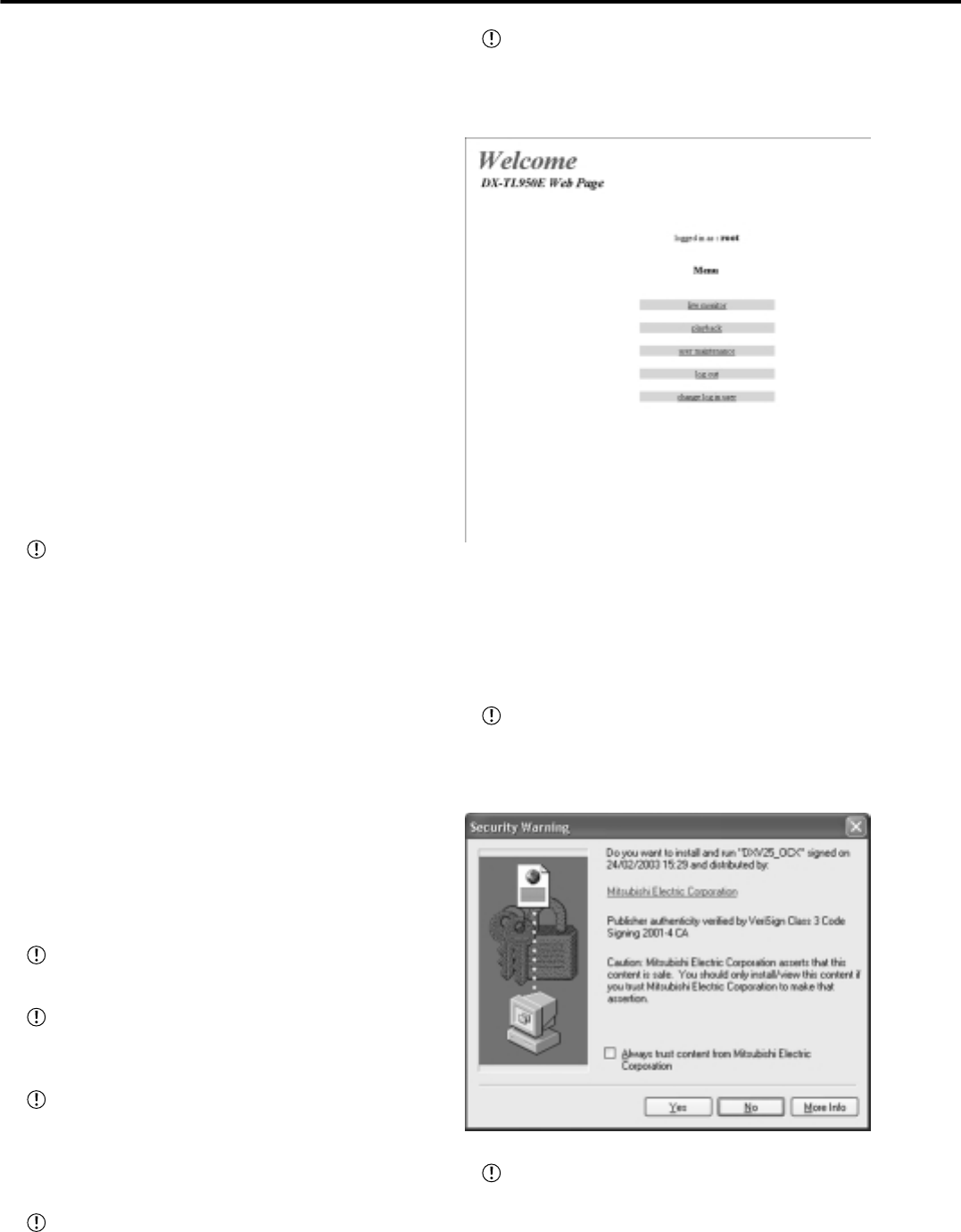
•••••••••••••••••••••••••••••••••••••••••••••••••••••••••••••••••••••••••••••••••••••••••••••••••••••••••••••••••••••••••••••••••••••••••••
78
3-1. (If you make an error in entering the userID or password
• • • )
• The “[Rejection]” screen will appear.
3-2. Select “[Back to Authentication]” and either left-click or
press ENTER.
• The “[Authentication]” screen will appear.
3-3. Follow the steps in step 2-1 and enter the correct “userID”
and “password”.
4-1. (If you do not log in • • • )
Select “If you don’t want to log in, click here to exit.” and left-
click.
4-2. The message “SessionID removed in recorder & browser.
Please shut this Web Browser down to clear of your browser’s
cache.” will display. Close the Web Browser.
5-1. (To change password • • • )
The password can be changed in the “[Authentication]” screen
only by the user who has the authorization to change a
password. Follow the instructions in the menu and enter the
present “userID” and “password”.
5-2. Enter the new password in “new password:” and again in
“retype new password:”.
The number of characters that can be used in
registering a password is 16. Both alphabet letters
and numbers can be used with a distinction made
between upper and lower case. You cannot use
spaces.
5-3. To change into a new password, select “change” and left-
click or press ENTER. To stop the change, select “clear”, and
left-click or press ENTER.
♦ Welcome
This is the screen for selecting, from “Menu”, “live moni-
tor” with which live pictures will be retrieved and dis-
played, “playback” with which pictures that have already
been recorded will be retrieved and displayed, “user
maintenance”, with which the settings for user authori-
zation will be configured, “log out” for ending a job, or
“change log in user” for making a change in the logged-
in user.
Depending on what the user’s authorization is,
there are certain menus that cannot be selected.
During playback or during a search, this device
will stop playback or search mode when a request
for the acquisition of live images is transmitted.
The transfer rate during transmission depends
on the standard environment and load status of the
recorded. To ensure stable transmission, use an
image transfer rate that best matches the current
usage conditions.
The user’s sessionID (connection data) will be
lost in 5 minutes from the final operation that includes
image retrievals. If no operations are made within
that 5 minutes, no other operations can be made
after that so close the browser and then log in again.
Live and recorded images can be acquired when
the recorder POWER button is lit.
1. Select the desired “Menu” and left-click.
• Live monitor
Retrieves live images and displays the images on the
PC screen.
1. Select “live monitor” and left-click.
• The “live monitor” screen will display.
When image acquisition is tried for the first time
with the Web browser of a personal computer, a mes-
sage as shown below will be displayed. Please click
“Yes”.
When a live picture is acquired from the recorder
and the <OUTPUT B ON/OFF> setting is “ON”, the
updating speed for the Live monitor screen de-
creases. It is recommended to set the <OUTPUT B
ON/OFF> setting to “OFF”.
Communications by Web Browser (continued)
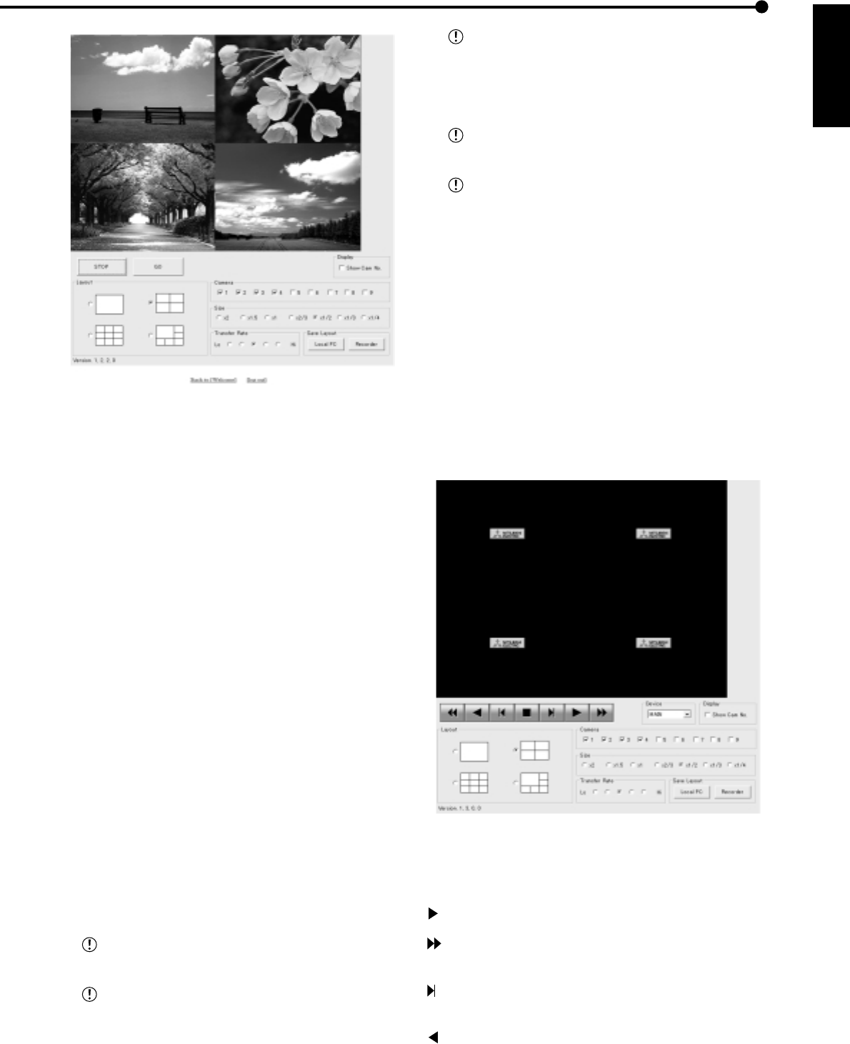
ENGLISH
79
••••••••••••••••••••••••••••••••••••••••••••••••••••••••••••••••••••••••••••••••••••••••••••••••••••••••••••••••••••••••••••• Operations
<Explanation of functions>
STOP : Stops the retrieval of an image.
GO : Starts (or restarts) the retrieval of
an image.
Display : For selecting either the display or
non-display of a camera number.
Layout : For selecting from the 4 types of
display patterns.
( default : split4 screen )
Camera : Selects the camera number that
you want to display and check.
Size : Selects one of 7 patterns for the
screensize: x2, x1.5, x1, x2/3,
x1/2, x1/3, x1/4.
Transfer Rate : Selects one of 5 stages from “Lo”
to “Hi” for image retrieval speed.
( default : middle )
Save Layout : The layout of the screen display is
registered to “Local PC” and
“Recorder”.
Back to [Welcome] : Returns to the “Welcome” menu.
[Log out] : For logging out.
The sequence in which camera numbers have
been selected is displayed from the top left.
The screen size regulated by “Size” is applied to
the display field at the farthest upper left point in the
screen layout.
Setting “Transfer Rate” too far on “Hi” may
present obstacles to PC operation as determined
by the performance of the PC you are using. Please
set it to the appropriate rate to the image retrieval
speed of your machine.
Depending on the network capacity and the load
conditions, the transfer rate may not rise.
Only a user who has the authorization for
“Change Password” can store screen layouts in the
“Recorder” side using “Save Layout”. If the user who
has authorization for “Change Password” stores
screen layouts in both “Local PC” and “Recorder”,
the information for “Local PC” is given priority. When
storing layouts in “Local PC”, only one layout can
be stored for one PC, even if users are different. To
delete layouts that are stored in “Local PC”, delete
the “Cookies” in the browser.
• Playback
Retrieves, plays back and search for images that have
been recorded by the recorder.
1. Select “playback” and left-click.
• The “playback” screen appears.
2. Press the PLAY button to start playback.
<Function description>
: Press to start playback.
: Press to start speed search in the forward di
rection at speeds of x2, x4, x8 and x16.
: Press to frame-by frame playback in the for
ward direction.
: Press to start reverse playback.
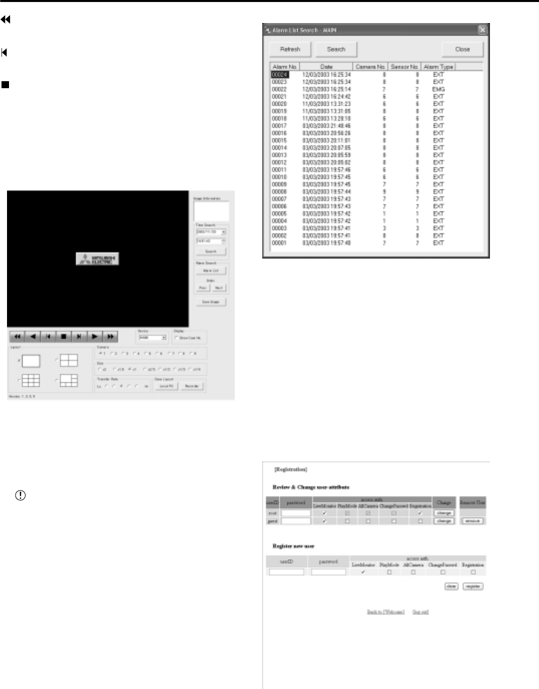
•••••••••••••••••••••••••••••••••••••••••••••••••••••••••••••••••••••••••••••••••••••••••••••••••••••••••••••••••••••••••••••••••••••••••••
80
: Press to start speed searches in the reverse
direction at speeds of x2, x4, x8 and x16.
: Press to frame-by-frame playback in the re
verse direction.
: During playback or searching, press to stop
playback for still frame.
Device : Selects the HDD for playback and search.
( default : MAIN )
• The following searches can be selected in single-screen
display.
The date and time and the camera number for the im-
age acquired are displayed in “Image Information”. Click-
ing “Save Image” stores the picture that is freeze-frame
displayed in the PC in bit map format.
For the recorded image data search function,
select single screen display at the “playback” screen
to use each search mode while playback is stopped.
• Time Search
Select the date and time and click “Search”.
• Alarm Search
Click “Alarm List” and the “Alarm List Search - MAIN”
screen will appear in the sub-screen. Select the “Alarm
No.” desired, and then click “Search”.
Click “Refresh” to re-acquire the “Alarm List”, and click
“Close” to hide the “Alarm List Search - MAIN” menu.
• Index Search
Click “Prev” for an index search in the reverse direction
and click “Next” for an index search in the forward direc-
tion.
• User maintenance
This is the screen for changing the settings for regis-
tered user authorization and for deleting a registration.
It can also be used for registering new users.
1. Select “user maintenance” and left-click.
• The “[Registration]” screen will appear.
2-1. (To change registered user settings • • • )
Select the userID for changing the settings in the “Review &
Change user-attribute” settings.
• Select the items that you want to change.
Communications by Web Browser (continued)

ENGLISH
81
••••••••••••••••••••••••••••••••••••••••••••••••••••••••••••••••••••••••••••••••••••••••••••••••••••••••••••••••••••••••••••• Operations
<User authorization>
Live Monitor : Allows acquisition of live images.
It is a mandatory rank to be
registered.
Play Mode : Allows acquisition of recorded im
ages. This authorization is only to
a one user.
All Camera : Allows the acquisition of images
from a covert camera.
(You also can acquire images
from cameras that have the
“COVERT CAMERA SETTING”
set to “OFF”. )
Change Password : Allows the changing of user’s
password. Moreover, a screen
layout can be saved to the
recorder.
Registration : Allows the viewing and editing of
user registration information.
Certain items cannot be selected depending on
what the user authorization is.
“Registration” authorization can be used by only
one user. From the time that a user logs in until that
user logs out and gives up authorization, any other
user that logs in is regarded as a user who does
not have “Registration” authority.
“Play Mode” authorization can only be used by
one user. From the time that a user logs in until that
user logs out and gives up authorization, any other
user that logs in is regarded as a user who does
not have “Play Mode” authority.
2-2. (To change settings • • • )
Select “change” and left-click. The “[Change Confirmation]”
screen will appear.
2-3. If you want to make the change, left-click “change”. If
you want to cancel a change, left-click “cancel”.
2-4. (When you have selected “change” • • • )
The “[User’s Attribute Changed]” screen will appear, so then
left-click “Back to [Registration]”.
• The return will be made to the “[Registration]” screen.
2-5. (When you have selected “cancel” • • • )
• The return will be made to the “[Registration]” screen.
3-1. (When you have deleted a registered user • • • )
Left-click on “remove” in the userID that you want to delete in
“Review & Change user-attribute”.
• The “[Remove confirmation]” screen will appear.
3-2. If you want to delete it, left-click “remove”. If you don’t
want to delete it, left-click “cancel”.
3-3. (If you have selected “remove” • • • )
The “[User Removed]” screen will appear, so left-click “Back
to [Registration]”.
• The return will be made to the “[Registration]” screen.
3-4. (If you have selected “cancel” • • • )
• The return will be made to the “[Registration]” screen.
4-1. (To register a new user • • • )
Enter the new userID and new password in “Register new
user”.
4-2. Refer to step 2-1, select the “access auth.” desired and
check it.
A userID with the same name cannot be regis-
tered. The maximum number of characters that can
be used in registering a password is 16. Both alpha-
bet letters and numbers can be used with a distinc-
tion made between upper and lower case. You can-
not use spaces.
4-3. If you want to make a new registration, left-click “register”.
If you want to cancel a new registration, left-click “cancel”.
4-4. (If you have selected “Register” • • • )
It will be added to “Review & Change user-attribute”.
4-5. (Selecting “cancel” • • • )
Clears the specified contents.
• Log out
In this screen, assign “Log out” settings to end the job.
1. Select “log out” and left-click.
• The “[log out]” screen will appear.
2. Close the Web Browser.
If the browser is closed without correctly operat-
ing the log out, the user’s sessionID will be saved
for 5 minutes, If the Log in is made with the same
userID within that 5 minutes, operation limits may
take effect.
• Change log in user
This screen is for changing the logged in user.
1. Select “change log in user” and left-click.
• The “[Authentication]” menu appears.

82
••••••••••••••••••••••••••••••••••••••••••••••••••••••••••••••••••••••••••••••••••••••••••••••••••••••••••••••••••••• Operations
2-1. (To change the logged in user • • • )
In the “Log in ( or log in as a different user ):” settings, execute
step 2-1 and 2-2 in “
♦
AUTHENTICATION” and change the
logged in user.
• The logged in user is changed and the “Welcome” screen
appears.
2-2. (If the log in is made without changing the user • • • )
Select “Back to [Welcome] as Current User” and left-click.
• The logged in user will remain as is and the “Welcome”
screen will appear.
2-3. (To log out • • • )
Select “If you don’t want to log in, click here to exit.” and left-
click.
Communications by Web Browser (continued)

ENGLISH
83
•••••••••••••••••••••••••••••••••••••••••••••••••••••••••••••••••••••••••••••••••••••••••••••••••••••••••••••• Recording Time Table
■ Continuous recording time table
♦ HDD continuous recording time (for 250GB drive)
Displays the estimated recordable time (when recording on a 250GB HDD).
The following table shows estimated recordable time when operating with 2 cameras and the
recording interval is set at a constant PPS rate given at the top of the column.
• Without Audio recording
PPS
GRADE
SUPER
HIGH
STD
BASIC
LONG
12.5P25P 8.333P 6.25P 5P 4.167P 3.125P 2.5P 1P 0.5P 0.25P 0.125P
NUMBER OF
RECORDING
FIELD
1d4h
1d13h
2d16h
3d17h
8d3h
2d9h
3d3h
5d8h
7d10h
16d7h
4d18h
6d7h
10d16h
14d20h
32d15h
3d13h
4d17h
8d
11d3h
24d11h
5d22h
7d21h
13d8h
18d13h
40d19h
7d3h
9d10h
16d1h
22d6h
48d23h
9d12h
12d14h
21d9h
29d16h
65d6h
11d21h
15d18h
26d17h
37d2h
81d14h
29d18h
39d9h
66d20h
92d17h
204d
59d12h
78d18h
133d17h
185d11h
408d
119d1h
157d12h
267d10h
370d22h
816d1h
238d3h
315d1h
534d21h
741d20h
1632d2h
5,140,000
6,800,000
11,550,000
16,020,000
35,250,000
• With Audio recording <Audio recording using 12.8KHz PCM sampling is possible.>
PPS
GRADE
SUPER
HIGH
STD
BASIC
LONG
12.5P25P 8.333P 6.25P 5P 4.167P 3.125P 2.5P 1P 0.5P 0.25P 0.125P
1d4h
1d13h
2d14h
3d15h
7d
2d9h
3d3h
5d5h
7d4h
14d1h
4d13h
6d1h
10d6h
13d22h
28d
3d13h
4d17h
7d16h
10d15h
21d
5d16h
7d14h
12d13h
17d4h
34d11h
6d19h
9d2h
15d1h
20d6h
40d1h
9d2h
12d3h
19d15h
26d3h
50d8h
11d8h
14d15h
23d23h
31d14h
59d14h
25d15h
33d21h
51d17h
65d6h
105d2h
45d19h
56d18h
81d12h
100d6h
141d12h
119d1h
157d12h
267d10h
370d22h
816d1h
238d3h
315d1h
534d21h
741d20h
1632d2h
d : day, h : hour
Continuous recordable time and the estimated time displayed on the menu screen is the continu-
ous recordable time when operating this unit and is not the product warranty period. Furthermore, it
is not the period that guarantees the operation of used parts.
Audio recording cannot be performed when “PPS” of “RECORD SETTING” are all set to smaller
than “0.333P” for normal recording.
• In this case, ( X ) appears to the right of recordable time display.
Audio recording cannot be performed when the camera selection for alarm recording is as fol-
lows:
“ALARM CH” : “A-PPS” of all cameras set for alarm recording are set to smaller than “0.333P”.
“ALARM PLUS”, “ALARM25”: “PPS” and “A-PPS” of all cameras set for normal recording and alarm
recording are set to smaller than “0.333P”.
: Since audio recording cannot be made during recording interval of 0.25P and 0.125P, even
when the recording with audio recording is set to ON, the recordable time is the same for when
setting audio recording to OFF.
Recording time table
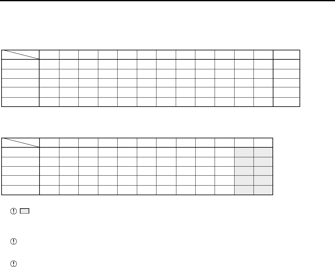
84
••••••••••••••••••••••••••••••••••••••••••••••••••••••••••••••••••••••••••••••••••••••••••••••••••••••• Recording Time Table
♦ Compact Flash Card continuous recording time (for 64MB)
Displays the estimated recordable time (when recording on a 64MB Compact Flash Card).
• Without Audio recording
PPS
GRADE
SUPER
HIGH
STD
BASIC
LONG
12.5P25P 8.333P 6.25P 5P 4.167P 3.125P 2.5P 1P 0.5P 0.25P 0.125P
NUMBER OF
RECORDING
FIELD
20s
30s
50s
1m10s
2m40s
40s
1m
1m40s
2m30s
5m30s
1m30s
2m
3m30s
5m
11m
1m10s
1m30s
2m40s
3m40s
8m10s
2m
2m40s
4m30s
6m10s
13m
2m20s
3m10s
5m20s
7m30s
16m
3m10s
4m10s
7m10s
10m
22m
4m
5m20s
9m
12m
27m
10m
13m
22m
31m
1h
20m
26m
45m
1h
2h10m
40m
53m
1h30m
2h
4h30m
1h20m
1h40m
3h
4h10m
9h10m
1,200
1,600
2,700
3,700
8,300
• With Audio recording <Audio recording using 12.8KHz PCM sampling is possible.>
PPS
GRADE
SUPER
HIGH
STD
BASIC
LONG
12.5P25P 8.333P 6.25P 5P 4.167P 3.125P 2.5P 1P 0.5P 0.25P 0.125P
20s
30s
50s
1m10s
2m20s
40s
1m
1m40s
2m20s
4m40s
1m30s
2m
3m20s
4m40s
9m30s
1m10s
1m30s
2m30s
3m30s
7m
1m50s
2m30s
4m10s
5m50s
11m
2m10s
3m
5m
6m50s
13m
3m
4m
6m40s
8m50s
17m
3m50s
4m50s
8m
10m
20m
8m40s
11m
17m
22m
35m
15m
19m
27m
34m
48m
40m
53m
1h30m
2h
4h30m
1h20m
1h40m
3h
4h10m
9h10m
: Since audio recording cannot be made during recording interval of 0.25P and 0.125P, even
when the recording with audio recording is set to ON, the recordable time is the same for when setting
audio recording to OFF.
Recalculate the values on the recording times chart according to the capacity of the CFC you are
using. For example, for a 128MB CFC, multiply all the values by two.
For usable Compact Flash Card, check with your dealer of purchase.
Recording time table (continued)

85
ENGLISH
••••••••••••••••••••••••••••••••••••••••••••••••••••••••••••••••••••••••••••••••••••••••••••••••••••••••••••••Troubleshooting
If problems with the unit persist even after you’ve followed the suggestions below, please disconnect the power cord
and contact the retailer from whom you purchased the unit.
The unit will not turn on.
Power is on, but the unit
will not operate.
Images are not appearing
on the monitor.
The quality of the monitor
picture is poor.
The unit will not start
recording.
The unit will not stop
recording.
The unit will not perform
Repeat Recording.
The unit will not perform
Timer Recording.
The unit will not perform
Alarm Recording.
• Is the power cord properly plugged in?
• Is the LOCK indicator light on?
• Is the TIMER button light on?
• Is the MAIN switch on the rear set to “OFF” ?
• Is the LOCK indicator light on?
• Is the POWER button blinking?
(The unit cannot be operated when the POWER button is flashing.)
• It is possible that the safety features are in operation.
Restart the unit by pressing the RESET button located on the back
of the unit using a ballpoint pen or similar object.
• Are the monitor and camera(s) connected correctly?
• Is the unit receiving an input signal from the selected camera?
Check this by setting the unit to SPLIT9.
• Is “OUTPUT B ON/OFF” set to “ON”?
Video from OUTPUT B will not be displayed when “OFF”.
• Is the connecting cord connected correctly?
• Is the camera’s focus adjusted correctly?
•
Is the “HDD REPEAT REC MAIN” set to “OFF” or “STANDBY” and
“HDD REPEAT REC SUB” set to “OFF”?
• The unit begins recording only after the specified recording time.
Was the unit stopped during the specified recording time?
• Is the LOCK indicator light on?
• During normal recording, alarm recording and emergency
recording, press the REC/STOP button for more than 1 second.
• Is timer recording in progress?
To stop timer recording, press the TIMER button again for more
than 1 second.
• Is the “HDD REPEAT REC MAIN” and “HDD REPEAT REC SUB”
set to “ON”?
• Are the date and current time set accurately?
• Are the Recording Start-/End-times and the recording interval
set correctly?
•
Is the “HDD REPEAT REC MAIN” set to “OFF” or “STANDBY” and
“HDD REPEAT REC SUB” set to “OFF”?
• Is the “A-PPS” in the <RECORD SETTING> set as “- - - - - -”?
• Is the SUB HDD recordable capacity full?
• Is the unit in timer recording stand-by mode?
(Is the TIMER button light on?)
• Are the peripheral switches, etc., connected correctly?
INSTALLATIONRECORDING
PagePlease consult the followingDescription of problem
-
11,56-58
10
13
11,56-58
10
13,74
15
36
37
-
-
47
22,23
11,56-58
10,23
10
47
20,21
44-46
47
41,42
47
10
15
Troubleshooting

86
••••••••••••••••••••••••••••••••••••••••••••••••••••••••••••••••••••••••••••••••••••••••••••••••••••••••••••••Troubleshooting
OTHERS
The unit will not perform
the motion detection
function.
The unit will not respond
to PC control.
There is a camera number
with a blue screen during
split screen display.
Button operation is not
working.
Cameras cannot be
switched with the
camera number buttons.
Unable to search.
• Is “TRIGGER” of the camera number that the motion detection
function is confirmed in the <ALARM SETTING> screen set as
“EXT” ?
• Is the “A-PPS” of the camera number that the motion detection
function is confirmed in the <RECORD SETING> screen set
as “- - - - - -”.
• Is the value in “MOTION THRESHOLD” of the <MOTION
DETECTION SETTINGS> screen larger than the value set in
“DETECTION MASK SETTING” ?
• Is the <RS-232C> set correctly ?
• Are the unit and computer connected correctly ?
• Is there a defect in the connecting cable ?
• Is the proper connecting cable being used ?
• The screens of camera number with no video signal input will be
blue even when setting for operation.
• Is the POWER button flashing?
(The unit cannot be operated when the POWER button is flashing?)
• Is the LOCK indicator light on?
• Is the Menu screen being displayed?
Camera number buttons cannot be used when the Menu screen
is displayed.
• Is the OUTPUT setup correct?
While the OUTPUT B indicator is turned off, operation of OUTPUT
A will function. While the OUTPUT B indicator illuminates, operation
of OUTPUT B will function.
• Is there a prompt to receive live images?
Search cannot be performed while receiving images.
PagePlease consult the followingDescription of problem
41
42
40
52
-
-
-
36
10
11,56-58
-
10
24,67,78
11,56-58
54
67
23,65,78
11
67
-
The unit will not perform
playback.
The Compact Flash Card
will not perform playback.
• Is the LOCK indicator light on?
• Has the image data been erased?
• Is the correct playback device selected?
• Is there a prompt to receive live images?
Playback cannot be performed while receiving images.
• Is the media correctly inserted?
• Is the correct playback device selected?
• Is the data of FSM2 format recorded?
PLAYBACK
Troubleshooting (continued)

87
ENGLISH
••••••••••••••••••••••••••••••••••••••••••••••••••••••••••••••••••••••••••••••••••••••••••Warnings and CALL OUT output
■ Warnings and their appropriate countermeasures
#1 Options in the CALL OUT options column:
• Selectable : CALL OUT output can be selected/de-selected on the menu.
• Fixed : a CALL OUT signal is emitted without prior selection of this function using the menu.
• None : no CALL OUT signal is emitted, but a warning indicator will appear on screen.
CALL OUT signal output can be stopped by pressing the WARNING RESET button.
Warning Display
CALL OUT
output
#1 page
Canceling
the warning Code
Status Countermeasure
REC/FULL
REC/SUB FULL
COPY/FULL
REST/FULL
REC/REM
COPY/SIZE/
DATA ERROR
REST/SIZE/
DATA ERROR
COPY/
MEDIA ERROR
REST/
MEDIA ERROR
COPY/NO MEDIA
REST/NO MEDIA
NO SIGNAL
(The warning will
indicate the number
of the non-functioning
camera. )
WNG1100
WNG1101
WNG3100
WNG4100
WNG1200
(MAIN)
WNG1201
(SUB)
WNG3701
WNG4701
WNG3702
WNG4702
WNG3703
WNG4703
WNG54 #3
47
72,73
-
-
72,73
72,73
-
11,72
11,72
15
36
22,23,
41-43
Selectable
None
Selectable
None
None
None
Fixed
• MAIN HDD recordable
capacity is full.
• SUB HDD recordable
capacity is full.
• Media recordable
capacity is full.
• The remaining HDD capa
-city has reached the value
set in HDD REMAIN.
• The data that is being
copied exceeds the
capacity ofCompact Flash
Card, or there is no
original data.
It restored from the
Compact Flash of a
different format.
• Error has occurred in the
media as Compact Flash.
• No inserted media as
Compact Flash.
• Video signal was lost for
more than 5 seconds
during recording.
Press the
WARNING
RESET button.
Press the
WARNING
RESET button.
Press the
WARNING
RESET button.
Press the
WARNING
RESET button.
Press the
WARNING
RESET button.
Press the
WARNING
RESET button.
Stop recording.
Output video
signals.
Press the
WARNING
RESET button.
• When the warning is
cancelled, the unit will start
over-writing the oldest data
remaining in the hard disk
drive.
• Copy data as necessary.
• Replace with new media.
• Replace media if necess
-ary.
• Copy data as necessary.
• Set the copy/restore
range again.
• Replace with new media.
• Check media in recording
device. (Insert the media
if there is none.)
• Insert the media.
• Check whether the unit
and camera are properly
connected, and that electri
-city is on.
• Check whether the visual
signal is being properly
outputted.
• Check to see if there is a
camera set for operation
with no video signal input.
Warnings and CALL OUT output

88
••••••••••••••••••••••••••••••••••••••••••••••••••••••••••••••••••••••••••••••••••••••••••Warnings and CALL OUT output
Warning Display
CALL OUT
output
#1 page
Canceling
the warning Code
Status Countermeasure
#2 : (The following numbers are in )
0 0 : MASTER 01 : SLAVE
2 0 : CFC
#3 : (The following numbers are in )
0 1 : CH 1 0 2 : CH 2 0 3 : CH 3
0 4 : CH 4 0 5 : CH 5 0 6 : CH 6
0 7 : CH 7 0 8 : CH 8 0 9 : CH 9
#4 : A warning display disappears automatically after 1 minute.
REC/RW
#4
COPY/RW
REST/RW
MIRROR
<DEVICE ERROR>
TEMP
FAN
COPY/OVER(RED)
COPY/OVER
(WHITE)
(NONE)
• Error has occurred during
writing ( or reading )of
data to HDD/media.
• One HDD could not be
detected during mirroring.
• Unable to recognize
HDD.
• Issued when in a high
temperature environment
within the tolerance level.
• The fan stopped.
• HDD recording has
overtaken copy recording.
Copy recording has
stopped.
• HDD recording is about
to
overtake copy recording.
• Reboots by watchdog
operation.
• Check the HDD/media.
• Reboot.
• Reboot.
• Turn off the power and
change the installation
condition.
• Turn off the power and
stop usage.
• Repair is requested.
• Stop HDD recording to
continue copy recording.
• Stop HDD recording to
continue copy recording.
• Stop copy recording to
continue HDD recording.
Press the
WARNING
RESET button.
Press the
WARNING
RESET button.
Turn off the
power.
Press the
WARNING
RESET button.
Lower
the temperature.
Press the
WARNING
RESET button.
Rotate the fan.
Press the
WARNING
RESET button.
Press the
WARNING
RESET button.
-
-
-
-
-
-
72,73
72,73
-
-
None
Fixed
Fixed
Fixed
Fixed
None
None
WNG13 #2
WNG33 #2
WNG43 #2
WNG6100
WNG6200
WNG5200
WNG5300
WNG3500
WNG3600
WNG5101
IMAGE MODIFIED
SYSTEM ERROR
#4
REC/
SYSTEM ERROR
#4
PLAY/
SYSTEM ERROR
#4
COPY/
SYSTEM ERROR
#4
REST/
SYSTEM ERROR
#4
• Video data that has been
altered was played back.
• System error has
occurred.
• Reboot.
• Check the HDD/media.
Press the
WARNING
RESET button.
Press the
WARNING
RESET button.
WNG5500
WNG5100
WNG14 #2
WNG24 #2
WNG34 #2
WNG44 #2
Fixed when
setting is
“ON”
Fixed
47
-
-
Warnings and CALL OUT output (continued)

89
ENGLISH
•••••••••••••••••••••••••••••••••••••••••••••••••••••••••••••••••••••••••••••••••••••••••••••••••••••••••••••••••••••••• Glossary
■ Glossary
• I/O terminals
Terms used for referring to both input and output.
• RS-232C
Connection standard used for handling data between de-
vices such as a PC, modem, etc. A standard when con-
necting a PC and modem. The upper limit for the commu-
nication speed of this standard is 115.2kbps and the maxi-
mum transfer distance is 15m. Since this standard only
defines the roles and physical characteristics of the con-
nector pins, there are various types of connectors such as
25-pin, D-sub, etc.
• Copy
Term used when copying part of data to an external stor-
age media. The term “copy” in this manual refers strictly to
the process of taking out only the data before and after
failures from continuous video to the Compact Flash Card
or video for analytical purposes.
• Compact Flash Card (CFC)
One of the standards for a compact memory card. The
Compact Flash Card has such merits as strong durability
and ease of handling.
• Partition
A partition is one of the many divided areas on the Hard
Disk.
■ Relation of recording operation to the number of cameras and recording interval settings
The recording pattern of this unit is as illustrated in the diagram below. Video data input from all the connected cameras
is recorded sequentially. ( Max. 50P recording interval during normal recording.)
C4-2
C3-2
C2-2
C1-2
C4-1
C3-1
C2-1
C1-1
50P
50P
50P
1 second
1 second
12:00:01~
12:00:02~
12:00:03~
C1-3
The example when setting
a setup of each channel to “1PPS”
Examples of time displayed
during playback.
• Hard disk drive (HDD)
Storage device using the same magnetic recording proc-
ess as tapes and is used in PCs. An aluminium disk coated
with magnetic materials is used on the surface as the stor-
age medium and since there is no contact during record-
ing/playback, there is no head wear. Data search is also
quick since recording is performed in numbered sections
called sectors.
• Media
Term was originally referred to media that transmits infor-
mation. Media mostly refers to hard disks, DVD RAM, MO
disks, magnetic tapes, and are commonly referred to as
storage media. Media types are largely categorized by the
recording method, such as optical disks, magnetic optical
disks, magnetic disks, etc.
• Capacity
Term to indicate the amount of data that can be stored in a
storage device such as memory, disk, etc., and unit is indi-
cated in B (bytes).
• Restore
Term referred to when copying data that has been backed-
up in a Compact Flash Card, etc., to the built-in hard disk
of the unit.
• Mirroring
One way of protecting data on magnetic disks. This func-
tion writes data alternately to 2 Hard disk drives with the
same capacity. However, there is the demerit of using 2
drives in place of 1, resulting in half the available space.
Glossary

•••••••••••••••••••••••••••••••••••••••••••••••••••••••••••••••••••••••••••••••••••••••••••••••••••••••••••••••••• Specifications
90
Specifications
Rated Power Supply: AC 100-240V 50/60Hz
Rated Input: 0.60 - 0.30A (100-240V)
Color System: PAL type color system.
Operating Temperature: 41°F-104°F (5°C to 40°C).
Relative Humidity: Max.80(%)
Altitude: Max.2000(m)
Dimensions: 300(Width) x 350(Depth) x 88(Height)(mm).
Weight: 5.0kg
Recording System Digital recording method using WAVELET compression.
Sampling 13.5MHz
Data Compression WAVELET
Compression Unit Field
Resolution 684 x 288
Recording Device 250GB HDD or higher
Video Input: 9 Input BNC-Connector: 1.0 V(p-p), 75 ohms.
Monitor Output: S-Connector: Y-Signal: 1.0 V(p-p), 75 ohms.
C-Signal: 0.3 V(p-p), 75 ohms.
2 Output BNC-Connector: 1.0 V(p-p), 75 ohms.
RCA-Pinplug:
1.0 V(p-p), 75 ohms.
Throughout Output: 9 Output BNC-Connector: 1.0 V(p-p), 75 ohms.
Audio Input: RCA-Pinplug: 308 mV(rms), 50 kohms.
Audio Output: 2 Output RCA-Pinplug: 308 mV(rms), 1 kohms.
Microphone Input: Ø3.5mm minijack: 0.346 mV(rms), 600 ohms.
Timer Program: 8 programs-Daily start and stop time for one week x 3set.
Memory Backup: Lasts for more than 1 month.
CONNECTORS
ALARM IN(1-9) Input: Terminal for starting alarm recording.
CLOCK ADJ Input: Terminal for adjusting clock.
REC Input: Terminal for start recording.
EMERGENCY Input: Terminal for start emergency recording.
GND: Terminal for ground.
MODE OUT(1-5) Output: Terminal for indication of recording selected mode.
DC 12V OUT Output: Terminal for DC 12V OUT. Max. Drive current 350mA DC. ( 350mA : 11.5 V typ ± 1.5 V )
CALL OUT/CALL OUT GND: Terminal for external warning device.
Rating:
MODE OUT(1-5) Active: “Low” Level. Max. Drive current 7mA DC.
Non active: Open. Max. Voltage +24V DC.
ALARM IN / CLOCK ADJ / Active: When terminals are short-circuited
REC/EMERGENCY or “Low” Level voltage is applied.
Non active: Open.
CALL OUT / Active: ON. Max. Drive current 7mA DC.
CALL OUT GND Non active: Open. Max. Voltage +24V DC.
RS-232C RS-232C (D-SUB 9pin) connector for connection with personal computer.
ETHERNET Connector form: RJ-45
Physical interface: 10BASE-T
Accessories
AC power cord (for U.K / for the Continent) 2
COMPACT FLASH slot cover (mounted on unit) 1
Compact Flash Card recording format Original format (FSM2)
Weight and dimensions shown are approximate.
Design and specifications are subject to change without notice.
SLD Security & Communications
The Old Forge, Ockham Lane, Ockham, Surrey GU23 6PH England
Phone +44.1483225633 · Fax +44.1483225634
sales@sld.co.uk · www.sld.co.uk
