Mitsubishi Electronics Lt 37131 Users Manual 853B541A90_VLP33 IB_20060721
LT-37131 to the manual c941270b-ff14-ba74-3104-ac12e76226d3
2015-02-09
: Mitsubishi-Electronics Mitsubishi-Electronics-Lt-37131-Users-Manual-556638 mitsubishi-electronics-lt-37131-users-manual-556638 mitsubishi-electronics pdf
Open the PDF directly: View PDF ![]() .
.
Page Count: 108 [warning: Documents this large are best viewed by clicking the View PDF Link!]

LCD FLAT PANEL HDTV
MODELS
LT-37131
LT-46131
OWNER’S GUIDE
• For questions:
- Call Consumer Relations at 800-332-2119.
- E-mail us at MDEAservice@mdea.com.
-
Visit our website at www.mitsubishi-tv.com.
• For information on Demo Mode and System
Reset, please see the back cover.
• To order additional remote controls or
Owner’s Guides, call 800-553-7278.
• Guidelines for setting up and using your new
widescreen TV start on page 13.
FCC Declaration of Conformity
Product: LCD HDTV Display
Models: LT-37131, LT-46131
Responsible Party: Mitsubishi Digital Electronics America, Inc.
9351 Jeronimo Road
Irvine, CA 92618-1904
Telephone: 800-332-2119
This device complies with Part 15 of the FCC Rules. Operation is subject to the following two conditions:
(1) This device may not cause harmful interference, and
(2) this device must accept any interference received, including interference that may cause undesired operation.
Note: This equipment has been tested and found to comply with the limits for a Class B digital device, pursuant to
part 15 of the FCC Rules. These limits are designed to provide reasonable protection against harmful interference in a
residential installation. This equipment generates, uses and can radiate radio frequency energy and, if not installed and
used in accordance with the instructions, may cause harmful interference to radio communications. However, there is no
guarantee that interference will not occur in a particular installation. If this equipment does cause harmful interference to
radio or television reception, which can be determined by turning the equipment off and on, the user is encouraged to
try to correct the interference by one or more of the following measures:
• Reorient or relocate the receiving antenna.
• Increase the separation between the equipment and the receiver.
• Connect the equipment into an outlet on a circuit different from that to which the receiver is connected.
• Consult the dealer or an experienced radio/TV technician for help.
Changes or modifications not expressly approved by Mitsubishi could cause harmful interference and would void the
user’s authority to operate this equipment.
WARNING: This product contains chemicals known to the State of California to cause cancer and/or birth defects or
other reproductive harm.
CAUTION
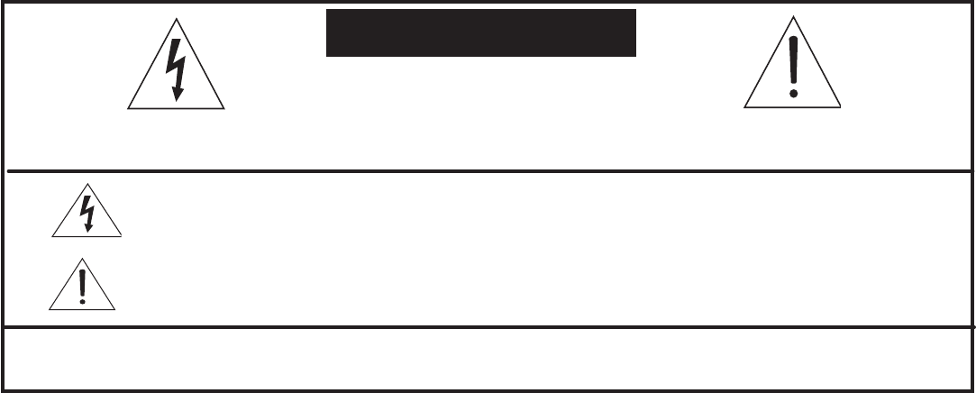
The lightning flash with arrowhead symbol within an equilateral triangle is intended to alert the
user of the presence of uninsulated “dangerous voltage” within the product’s enclosure that
may be sufficient magnitude to constitute a risk of electric shock.
The exclamation point within an equilateral triangle is intended to alert the user to the pres-
ence of important operating and maintenance (servicing) instructions in the literature accom-
panying the appliance.
CAUTION: TO REDUCE THE RISK OF ELECTRIC SHOCK, DO NOT REMOVE COVER (OR BACK).
NO USER SERVICEABLE PARTS INSIDE. REFER SERVICING TO QUALIFIED SERVICE PERSONNEL.
RISK OF ELECTRIC SHOCK
DO NOT OPEN
C A U T I O N
WARNING: TO REDUCE THE RISK OF FIRE OR ELECTRIC SHOCK, DO NOT EXPOSE THIS
APPLIANCE TO RAIN OR MOISTURE.

For Your Records
Record the model number, serial number, and purchase date of your TV. The model and serial numbers are on the
back of the TV. Refer to this page when requesting assistance with this TV.
MODEL NUMBER (check one):
LT-37131
LT-46131
SERIAL NUMBER
PURCHASE DATE
Retailer Information
RETAILER NAME
LOCATION
Our Thanks...
Thank you for choosing Mitsubishi as your premier Home Entertainment provider.
This Owner’s Guide describes the features and functions of your Mitsubishi widescreen, high definition
TV. We urge you to examine this Owner’s Guide to become familiar with the innovative features and
operations this unique television offers.
The very core of our corporate philosophy is to provide our customers with the very best. Our
development team at Mitsubishi has worked to provide you with a television that defines “state-of-the-
art,” with the capability to meet your needs now and in the future.
Whether this is your first Mitsubishi electronic product, or an addition to your Mitsubishi collection, we
believe you and your family will continue to enjoy your Mitsubishi home theater for many years.
Thank you,
Mitsubishi Digital Electronics America, Inc.
Contents
Important Information About Your TV
General Warnings and Cautions, Notes on Installation and Operation ........................... 6
Cleaning Recommendations ............................................................ 7
Important Safeguards .................................................................. 8
Stand Removal Instructions ............................................................ 10
Chapter 1: Television Overview
Package Contents .................................................................... 12
Special Features of Your TV ............................................................ 12
Guidelines for Setting Up and Using Your New Widescreen TV ................................ 13
TV Front Panel, Power Button and Indicators
Control Panel .................................................................... 15
System Reset Button ........................................................... 15
A/V Reset .................................................................... 15
Input 3 Jacks ................................................................. 15
TV Indicators ..................................................................... 16
Manual and Power Swivel .............................................................. 16
CableCARD™ Technology ............................................................. 17
Back and Side Panels ................................................................. 18
Chapter 2: TV Connections
Before You Begin
Choosing a Language for Menus ..................................................... 22
ClearThought® Easy Connect Auto Input Sensing ....................................... 22
Digital Video and Home Recording ................................................... 23
Connection Types ................................................................. 24
Cable Management ............................................................... 25
HDTV Cable Box or Satellite Receiver with Component Video ................................ 26
Standard Cable Box, Satellite Receiver, or Other Device with S-Video .......................... 26
Wall Outlet Cable (no cable box) ........................................................ 27
Antenna with a Single Lead ............................................................ 28
Antennas with Separate UHF and VHF Leads .............................................. 28
VCR to an Antenna or Wall Outlet Cable .................................................. 29
VCR to a Cable Box (Audio & Video) ..................................................... 30
H
DMI Device (Cable Box, Satellite Receiver, DVD Player, or Other Device) ............................ 31
DVI Video Device (Cable Box, Satellite Receiver, DVD Player, or Other Device) ................... 31
DVD Player with Component Video ...................................................... 32
A/V Receiver (Stereo System) .......................................................... 32
Older Cable Box ..................................................................... 33
Camcorder .......................................................................... 33
Chapter 3: TV Operation
Remote Control ...................................................................... 36
Choosing a Program Source ........................................................... 38
ChannelView™ Channel Listings ........................................................ 38
Status Display ....................................................................... 39
TV Signals and Display Formats ........................................................ 40

Split Screen ......................................................................... 42
Chapter 4: TV Menu Settings
3D Graphical Menu System .................................................... 46
Main Menu .......................................................................... 47
Setup Menu ......................................................................... 48
Input Name Menu .................................................................... 50
Icon Order Menu ..................................................................... 50
Channel Menu ....................................................................... 51
Captions Menu ...................................................................... 53
Parental Lock Menu .................................................................. 55
Setting a Pass Code ............................................................... 55
Lock TV by Time and Front-Panel Lock ............................................... 55
Rating Menus .................................................................... 55
Bypassing the Ratings Lock and Lock by Time ......................................... 57
V-Chip Signal Information
TV Ratings ....................................................................... 58
Movie Ratings .................................................................... 58
Audio/Video Menu ................................................................... 59
Audio Settings ................................................................... 60
Video Settings .................................................................... 61
Chapter 5: Operating Other Devices with the Remote Control
Functions Available for Other A/V Devices ................................................ 64
Programming the Remote Control ....................................................... 65
Programming Codes .................................................................. 66
Chapter 6: Using the TV with a Personal Computer
Setup .............................................................................. 76
Video Adjustments ................................................................... 76
Connecting a Computer to the TV ....................................................... 77
Adjusting Image Resolution ............................................................ 79
Computer Display Formats ............................................................. 80
Chapter 7: Using IEEE 1394 Devices
Overview ........................................................................... 82
Recording to IEEE 1394 Recordable Devices .............................................. 84
The TV Remote Control and IEEE 1394 Devices ............................................ 86
A/V Discs ........................................................................... 87
Switching Between Analog and Digital IEEE 1394 Outputs ................................... 88
Appendices
Appendix A: Bypassing the Parental Lock ................................................ 91
Appendix B: Specifications ............................................................ 93
Appendix C: Troubleshooting .......................................................... 95
Trademark and License Information ................................................... 102
Mitsubishi TV Software ................................................................ 103
Index ................................................................................... 105

6 Important Information About Your TV
Important Information About Your TV
WARNING: This product contains chemicals known to the State of California to cause cancer and/or birth defects or
other reproductive harm.
CAUTION: TO PREVENT ELECTRIC SHOCK, MATCH WIDE BLADE OF PLUG TO WIDE SLOT, FULLY INSERT.
TV WEIGHT: This TV is heavy! Exercise extreme care when lifting or moving it. Lift or move the TV with a minimum
of two adults. To prevent damage to the TV, avoid jarring or moving it while it is turned on. Always power off your TV
before moving it.
If Your TV Gets Damaged
Crystaline liquid may leak from the LCD panel and broken
glass may be scattered.
CAUTION: The crystaline liquid is toxic. Avoid contact
with your skin, eyes, or mouth.
• DO NOT touch the broken glass or crystaline liquid
with bare hands, as cuts, poisoning, and/or skin irria-
tion may occur.
• DO NOT let glass fragments or crystaline liquid get
into your eyes or mouth.
• Should either contact your eyes or mouth, rinse
the contacted area thouroughly with water and
consult your doctor.
Disposal of Your TV
The LCD panel contains a small amount of crystaline liquid
and the fluorescent tube in the panel contains mercury.
Both are toxic and should not be touched.
• DO NOT dispose of the TV with general household
waste.
• Follow your local laws and regulations for legal and
safe disposal of your TV.
• For disposal or recycling information, please contact
your local authorities or the Electronic Industries
Alliance at www.eiae.org.
Stand Requirement
CAUTION: The attached TV stand needs to be used or
other authorized optional mounting hardware.
For wall-mounting, the authorized hardware is:
Wall Mount Kit # PSM-2031 manufactured by Chief
Manufacturing, Inc. See page 10 for more information.
Use with other than the authorized accessories may
result in making the TV unstable which can cause
damage to the product or possible injury.
Custom cabinet installation must allow for proper air
circulation around the television.
NOTE TO CATV SYSTEM INSTALLER: THIS REMINDER
IS PROVIDED TO CALL THE CATV SYSTEM INSTALLER’S
ATTENTION TO ARTICLE 820-40 OF THE NEC THAT
PROVIDES GUIDELINES FOR THE PROPER GROUND-
ING AND, IN PARTICULAR, SPECIFIES THAT THE CABLE
GROUND SHALL BE CONNECTED TO THE GROUNDING
SYSTEM OF THE BUILDING, AS CLOSE TO THE POINT
OF CABLE ENTRY AS PRACTICAL.
Operating Notes
Demo Mode
This TV has a demo mode for use in retail stores. To turn
off demo mode:
1. Press
MENU
.
2. When the Main menu appears with Setup highlighted,
press
ENTER.
3. When the Setup menu opens, press to highlight the
on-screen Demo Mode Off button.
4. Press
ENTER
.

Important Information About Your TV 7
TV Software
Unauthorized Software
Do not attempt to update the software of this TV with
software or cards that are not provided by or authorized
by Mitsubishi Digital Electronics America, Inc. Non-autho-
rized software may damage the TV and will not be covered
by the warranty.
Cleaning Recommendations
Normally, light dusting with a dry, non-scratching duster
will keep your TV clean. If cleaning beyond this is needed,
please use the following guidelines:
First, turn off the TV and unplug the power cord from the
power outlet.
Top and Sides of the TV
• Gently wipe down your TV with a soft, non-abrasive
cloth such as cotton flannel or a clean cloth diaper,
lightly moistened with water. Dry with a second dry,
soft, non-abrasive cloth.
• For oily dirt, add a few drops of mild liquid detergent,
such as dishwashing detergent, to the water used to
moisten the cloth. Rinse with a second cloth moist-
ened only with water. Dry with a third dry, soft, non-
abrasive cloth.
LCD Screen Cleaning
• Only use a soft, dry cloth to clean the screen. Do
not use any liquids.
• Wipe the screen gently with an up and down motion.
• Clean the entire screen evenly, not just sections of the
screen.
General Cleaning Warnings
• DO NOT use any liquid to clean the screen. Only
use a dry, soft cloth.
For cleaning TV sufaces other than the screen:
• DO NOT allow liquid to enter the TV through the venti-
lation slots or any crevice.
• DO NOT use any strong or abrasive cleaners, as these
can scratch the surfaces.
• DO NOT use any cleaners containing ammonia,
bleach, alcohol, benzene, or thinner, as these can dull
the surfaces.
• DO NOT spray liquids or cleaners directly on the TV’s
surfaces.
• DO NOT scrub or rub the TV harshly. Wipe all sur-
faces gently.
IMPORTANT
DO NOT apply any type of liquid
to the surface of the TV screen.

8 Important Information About Your TV
Important Safeguards
Please read the following safeguards for your TV and retain for future reference. Always follow all warnings and instruc-
tions marked on the television.
1. Read, Retain and Follow All Instructions
Read all safety and operating instructions before operating the TV. Retain the safety and operating instructions
for future reference. Follow all operating and use instructions.
2. Heed Warnings
Adhere to all warnings on the appliance and in the operating instructions.
3. Cleaning
Unplug the TV from the wall outlet before cleaning. Do not use liquid, abrasive or aerosol cleaners. Cleaners
can permanently damage the cabinet and screen. Use a lightly dampened cloth for cleaning.
4. Attachments and Equipment
Never add any attachments and/or equipment without approval of the manufacturer as such additions may
result in the risk of fire, electric shock or other personal injury.
5. Water and Moisture
Do not use the TV where contact with or immersion in water is possible. Do not use near bath tubs, wash
bowls, kitchen sinks, laundry tubs, swimming pools, etc.
6. Accessories
Do not place the TV on an unstable cart, stand, tripod, or table. The TV may fall,
causing serious injury to a child or adult and serious damage to the TV. Use only with a
cart, stand, tripod, bracket or table recommended by the manufacturer, or sold with the
TV. Any mounting of the TV should follow the manufacturer’s instructions, and should
use mounting accessories recommended by the manufacturer.
An appliance and cart combination should be moved with care. Quick stops, excessive
force, and uneven surfaces may cause the appliance and cart combination to overturn.
7. Ventilation
Slots and openings in the cabinet are provided for ventilation and to ensure reliable operation of the TV and to
protect it from overheating. Do not block these openings or allow them to be obstructed by placing the TV on
a bed, sofa, rug, or other similar surface. Nor should it be placed over a radiator or heat register. If the TV is to
be placed in a rack or bookcase, ensure that there is adequate ventilation and that the manufacturer’s instruc-
tions have been adhered to.
8. Power Source
This TV should be operated only from the type of power source indicated on the marking label. If you are not
sure of the type of power supplied to your home, consult your appliance dealer or local power company.
9. Grounding or Polarization
This TV is equipped with a polarized alternating current line plug having one blade wider than the other. This
plug will fit into the power outlet only one way. If you are unable to insert the plug fully into the outlet, try
reversing the plug. If the plug should still fail to fit, contact your electrician to replace your obsolete outlet. Do
not defeat the safety purpose of the polarized plug.
10. Power-Cord Protection
Power-supply cords should be routed so that they are not likely to be walked on or pinched by items placed
upon or against them, paying particular attention to cords at plugs, convenience receptacles, and the point
where they exit from the TV.
11. Lightning
For added protection for this TV during a lightning storm, or when it is left unattended and unused for long
period of time, unplug it from the wall outlet and disconnect the antenna or cable system. This will prevent
damage to the TV due to lightning and power-line surges.

Important Information About Your TV 9
Important Safeguards, continued
12. Power Lines
An outside antenna system should not be located in the vicinity of overhead power lines or other electric light or
power circuits, or where it can fall into such power lines or circuits. When installing an outside antenna system,
extreme care should be taken to keep from touching such power lines or circuits as contact with them might be
fatal.
13. Overloading
Do not overload wall outlets and extension cords as this can result in a risk of fire or electric shock.
14. Object and Liquid Entry
Never push objects of any kind into this TV through openings as they may touch dangerous voltage points or
short-out parts that could result in fire or electric shock. Never spill liquid of any kind on or into the TV.
15. Outdoor Antenna Grounding
If an outside antenna or cable system is connected to the TV, be sure
the antenna or cable system is grounded so as to provide some pro-
tection against voltage surges and built-up static charges.
Article 810 of the National Electric Code, ANSI/NFPA No. 70-2002,
provides information with respect to proper grounding of the mast
and supporting structure, grounding of the lead in wire to an antenna
discharge unit, size of grounding conductors, location of antenna dis-
charge unit, connection to grounding electrodes, and requirements
for the grounding electrode.
16. Servicing
Do not attempt to service this TV yourself as opening or removing
covers may expose you to dangerous voltage or other hazards. Refer all servicing to qualified service person-
nel.
17. Damage Requiring Service
Unplug the TV from the wall outlet and refer servicing to qualified service personnel under the following condi-
tions:
(a) When the power-supply cord or plug is damaged.
(b) If liquid has been spilled, or objects have fallen into the TV.
(c) If the TV has been exposed to rain or water.
(d) If the TV does not operate normally by following the operating instructions, adjust only those controls that
are covered by the operating instructions as an improper adjustment of other controls may result in damage
and will often require extensive work by a qualified technician to restore the TV to its normal operation.
(e) If the TV has been dropped or the cabinet has been damaged.
(f) When the TV exhibits a distinct change in performance - this indicates a need for service.
18. Replacement Parts
When replacement parts are required, be sure the service technician has used replacement parts specified by
the manufacturer or have the same characteristics as the original part. Unauthorized substitutions may result in
fire, electric shock or other hazards.
19. Safety Check
Upon completion of any service or repair to the TV, ask the service technician to perform safety checks to
determine that the TV is in safe operating condition.
20. Heat
The product should be situated away from heat sources such as radiators, heat registers, stoves or other prod-
ucts (including amplifiers) that produce heat.
ANT E N NA
LE AD IN W IR E
ANT E N NA
DIS C HAR G E U NIT
(NE C A R T I C L E 810 -20 )
G R O UNDIN G
C O N DU C T O R S
(NE C A R T I C L E 810 -21 )
G R O UND C L AMP S
P OW E R S E R V IC E G R OUNDING
E L E C T R O DE S Y S T E M
(NE C AR T 250, P AR T H)
G R O UND C L AMP
E LE C TR IC
S E R V IC E
E Q UIP ME N T
NE C — N AT IO NA L E L E C T R I C AL C O DE
E X AMP L E O F ANT E NNA G R O U ND IN G
10 Important Information About Your TV
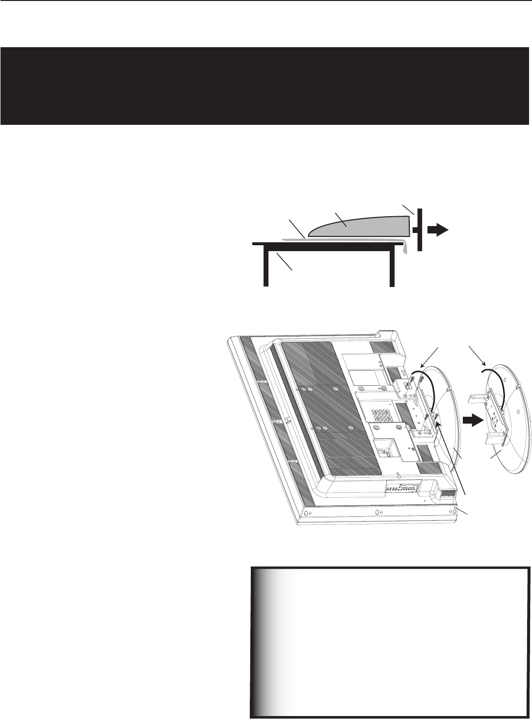
Stand Removal Instructions
1. Before starting to remove the stand, make
sure to disconnect the AC power cord from
the AC power outlet.
2.
Spread the protective sheet that was wrapped
around the TV on a flat, even surface (such
as a sturdy table). The protective sheet will
help prevent the display from being damaged.
IMPORTANT: To avoid damaging the screen,
make sure there are no foriegn objects
under or on top of the protective sheet.
3. With two people firmly grasping the left and
right sides of the
TV
, gently place the
TV
face
down on the protective sheet with the display
stand hanging over the edge of the table.
See the illustration to the right.
4. LT-37131 model: Disconnect the Power
Swivel Cable from the
TV
only.
LT-46131 model: Skip Step 4. This model
does not include the Power Swivel feature.
Both TV models can be swiveled manually
thirty degrees left and right.
5. Use a Philips screwdriver to remove the four
(4) stand screws. See the illustration to the
right.
6. While one person holds on to the TV with
both hands, the other person grasps the
plastic portion of the stand (see illustration
to the right) and removes the stand by pulling
it away from the TV in the direction of the
large arrow shown in both illustrations.
Place the stand and screws in a safe place
for future use.
7. The
TV
is now ready for mounting. Refer to
the instructions provided with the Wall Mount
Kit (purchased separately).
Wall Mount Kit
To order a Wall Mount Kit (Part #
PSM-2031)
:
Please call the
Mitsubishi
Parts Department at
(800) 553-7278, or call Chief Manufacturing,
Inc.
at (800) 582-6480.
Note: Complete wall-mounting instructions
are included with the wall mount
kit.
CAUTION
• A minimum of TWO PEOPLE are needed to safely remove the stand.
• One person needs to hold the TV, while the other person removes the stand.
• Failure to follow these recommendations may result in personal injury as well as damage to the product.
Before attaching the wall mount kit to the TV, b
e sure
to
connect all necessary cables to jacks on the
back of the TV. After wall-mounting, these jacks
will not be accessible.
If you plan to connect a PC to the TV, before wall-
mounting be sure to connect a DVI cable (or a
DVI/VGA
adapter
cable
) to the PC-DVI video input
on the back of the
TV
. For PC audio, connect an
RCA cable to the PC-DVI right/left audio inputs.
IMPORTANT

1
Television Overview
Package Contents .................................. 12
Special Features of Your TV ............................ 12
Guidelines for Setting Up and Using Your New Widescreen TV . . . 13
TV Front Panel, Power Button and Indicators
Control Panel ..................................... 15
TV Indicators ..................................... 16
Manual and Power Swivel ............................. 16
CableCARD™ Technology ............................. 17
Back and Side Panels ................................ 18
12 Chapter 1. Television Overview
Package Contents
Please take a moment to review the following list of items to ensure
that you have received everything.
1. Remote Control
2. Two AA Batteries
AA
AA
3. Cable Tie (see Cable Mangament, in
Chapter 2)
4. Product registration card (not pictured)
5. Owner’s Guide (not pictured)
6. Quick Reference Guide (not pictured)
Special Features of Your TV
Your new high-definition widescreen 1080p LCD television has many special features that make it the perfect center of
your home entertainment system, including:
16:9 Widescreen Picture Format
Enjoy a full theatrical experience in the comfort of your home. View pictures as film directors intended them. Digital TV
broadcasts, DVDs and newer video game consoles support this widescreen format.
Integrated HDTV Tuner
Your widescreen Mitsubishi HDTV has an internal HDTV tuner able to receive both over-the-air HDTV broadcasts (received
via an antenna) and non-scrambled digital cable broadcasts, including non-scrambled HDTV cable programming.
High-Definition Video Inputs
Two Component Video Inputs, also called Y/Pb/Pr inputs. These inputs receive standard analog video formats
of 480i, 480p, 720p and 1080i high-definition signals. This provides a high level of flexibility when connecting DVD
players/recorders, cable boxes, and satellite receivers.
Two HDMI Inputs that accept digital 480i, 480p, 720p, 1080 and 1080p video signals plus PCM digital stereo
signals. Used with an adapter, these inputs also accept compatible DVI video signals. HDMI inputs provide addi-
tional high-performance, high-definition connections for maximum flexibility in your choice of home theater prod-
ucts. The HDMI inputs are HDCP copy-protection compatible.
Two IEEE 1394 Digital Interfaces that receive and send compressed digital signals, including high-definition
signals, along with digital audio and control signals between devices such as the TV, digital cable boxes, and
D-VHS digital video recorders.
ClearThought® Easy Connect Auto Input Sensing
ClearThought® automatically recognizes when you plug in an input and prompts you to assign a name to it. The TV
ignores any unused inputs, so the result is an uncluttered Input Selection menu where you can easily find and select
connected devices by name.
Full Specturm Color™
(LT-46131 Model only)
Mitsubishi’s Full Spectrum Color™ results in 25% more color than standard LCD. Reds and yellows become more
vivid and there are more available shades of Green, Cyan and Blue. The result is a more vivid and more realistic image.
Manual and Power Swivel
Both TV models (LT-37131 and LT-46131) allow you to swivel the TV manually up to 30 degrees from left to right. In
addtion, the LT-37131 model has the Power Swivel feature, which automatically swivels the TV left or right when you
press
or
on the remote control. Note: Power Swivel is not available while the TV is i
n Split Screen mode.
PC Connectivity
The display has a PC (DVI ) video connector that supports VGA, SVGA, XGA, or SXGA signals. Please
see Appendix B
for signal compatibility. Stereo audio inputs are also provided.

Chapter 1. Television Overview 13
Guidelines for Setting Up and Using
Your New Widescreen TV
Getting Started
1. Read the section entitled “Important Information
About Your TV” starting on page 5.
2. Choose a location for your TV.
• Allow at least four inches of space on all sides of
the TV help prevent overheating.
• Avoid locations where light may reflect off the
screen.
• See the stand requirements under “Important
Information About Your TV.”
3. Install the batteries in the remote control. See
chapter 3, “TV Operation,” for information on use
and care of the remote control.
4. Plug your TV into a power outlet. The
POWER
indicator
on the front of the TV will start blinking rapidly. After
the
POWER
indicator stops blinking, press the
POWER
key
to power on the TV.
5. When the Welcome screen appears the first time you
power on the TV, select a language for TV menus.
You can later change the language through the Setup
menu.
6. Some TVs are shipped from the factory with demo
mode active for use in retail stores. If demo mode is
active when you first turn on the TV:
a. Press
MENU
.
b. When the Main menu appears with Setup high-
lighted, press
ENTER.
c. When the Setup menu opens, press to highlight
the on-screen Demo Mode Off button.
d. Press
ENTER
.
7. Connect your other A/V devices to the TV and assign
device names to the TV inputs when prompted. See
chapter 2, “TV Connections,” for connection dia-
grams. You can reassign device names later if needed.
See “Input Name Menu” in chapter 4, “TV Menu
Settings.”
8. Memorize channels if you plan to watch over-the-air
channels or programming over direct cable. Channel
memorization may take up to 15 minutes to complete.
See “Setup Menu” in chapter 4, “TV Menu Settings.”
9. You can now start watching TV or you can perform
additional setup and customization through the TV
menus.
Additional TV Setup
1. To program the remote control to operate your other
A/V devices, see chapter 5, “Operating Other
Devices with the Remote Control.”
2. Review chapter 4, “TV Menu Settings,” to custom-
ize TV operation. Press the
MENU
key to enter the menu
system. Some examples of settings you may wish to
change include:
• Energy Mode. For faster power-on, keep the
Energy Mode set to Fast Power On. For lower
power consumption while the TV is off, use the
Low Power setting. See “Setup Menu.”
• Input Name. Change the device names that
appear in the Input Selection menu. See “Input
Name Menu.”
• Icon Order. Rearrange the device icons in the
Input Selection menu to put frequently used icons
near the front. See “Icon Order Menu.”
• FAV. Create lists of your favorite channels so you
can find them quickly. See “Channel Menu.”
• Clock. If you wish to schedule future recordings
or use the Timer feature to have the TV come on
automatically, you must first set the TV clock to
the correct time. See “Setup Menu.”
• Parental Lock. You can restrict TV viewing by
program rating or by time of day. You can also
disable the front-panel buttons—useful if you have
small children. See “Parental Lock Menu.”
• Video Settings. Change the video adjustments
to get the best picture for your viewing conditions.
See “Audio/Video Menu.”
Digital Cable Ready (CableCARD™)
Your widescreen Mitsubishi HDTV is “Plug-and-Play” digital cable ready. It can descramble a cable provider’s one-way
digital signals with the use of a CableCARD security module. The CableCARD is used in place of a traditional cable box
to access digital cable programming (including high definition). Contact your local cable provider for availability infor-
mation and service details.

14 Chapter 1. Television Overview
You may wish to change the Picture Mode from the
default Brilliant to either Bright or Natural, which
are suitable for most home viewing environments.
3. If you have IEEE 1394 A/V devices, see chapter 7,
“Using IEEE 1394 Devices,” for details on operating
such devices and using the TV to control recording.
TV Operation
Review chapter 3, “TV Operation,” for TV features
including:
• Input Selection (viewing source). Select a con-
nected program source to watch, such as a VCR,
DVD player, or antenna. Press
INPUT
on the remote
control to select from icons for the TV inputs. See
“Input Selection Menu.”
• Channel Listings. Press
GUIDE
to view
ChannelView™ channel listings. See
“ChannelView™ Channel Guide.”
Guidelines for Setting Up and Using
Your New Widescreen TV, continued
TV Tips
Turning the TV On or Off
To turn the TV on or off, point the remote control at the
front of the TV and press the
POWER
button. Alternatively,
press the
POWER
button on the front panel of the TV.
Controlling Sound Volume
Press
VOL
/ to adjust the sound level.
Changing Channels
To change channels:
• Enter the channel number using the number keys on
the remote control and press
ENTER
. For a two-part
digital channel, such as 3-1, press
3
—/CANCEL
1
to
enter a dash (separator).
• Press
CH
/ to change channels one channel at
a time.
• Press and hold
CH
/ to move quickly through
channels.
• Press
QV
(QuickView) to switch back to the previ-
ously tuned channel.
• Use the FAV (Favorites) feature to set up lists of
favorite channels and tune to them with the
FAV
key.
See “Channel Menu” in chapter 4.
NOTE: Memorize channels to make finding channels
easier. See “Setup Menu” in chapter 4, “TV
Menu Settings.”
• Picture Formats. Press
FORMAT
to cycle through
the available picture sizes and shapes to find the
one best suited to the program you’re watching.
See “TV Signals and Display Formats.”
• SPLIT. Press
SPLIT
to view two programs at the
same time. See “Split Screen Mode.”
Assistance
If you need assistance with this TV:
• For troubleshooting, service, and product support,
see Appendix D.
• For warranty information, see the TV warranty in
the back of this book.
Chapter 1. Television Overview 15
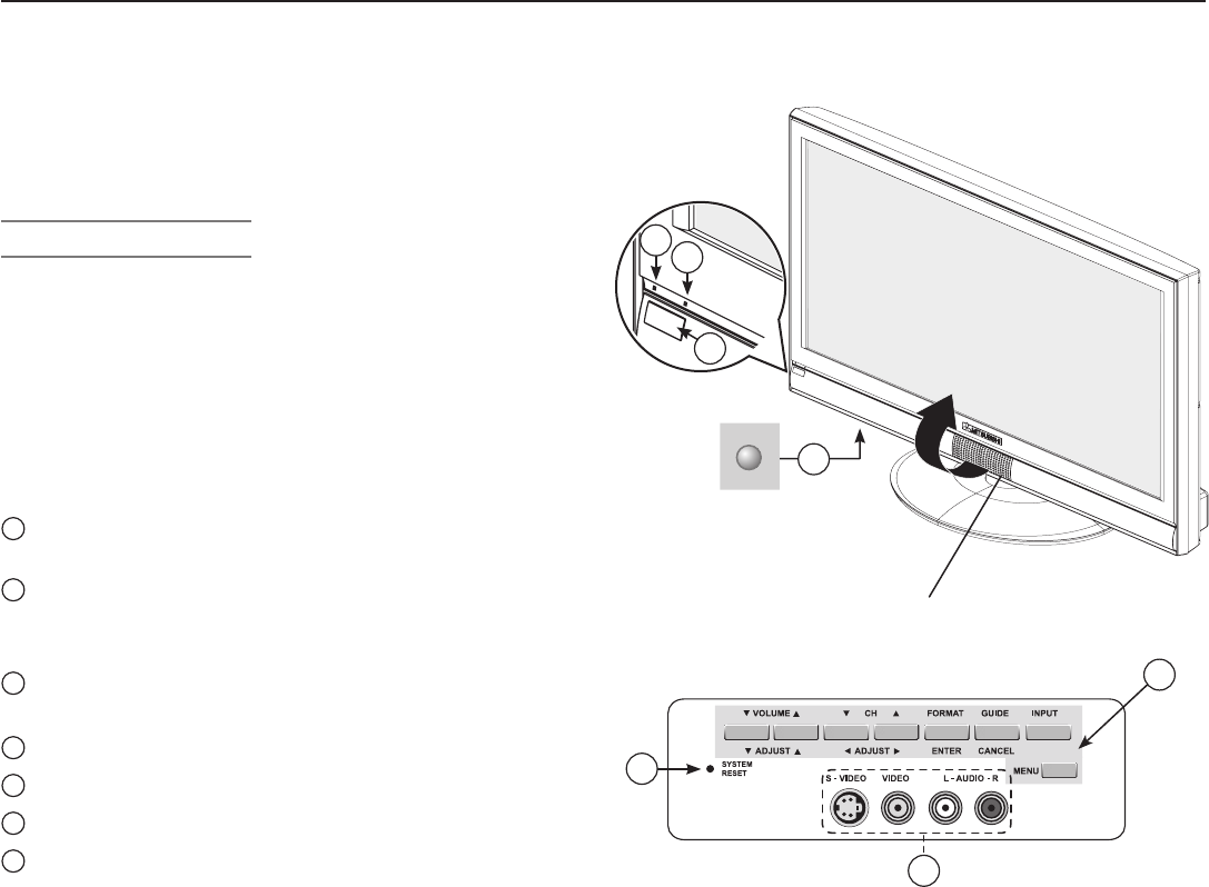
TV Front Panel, Power Button and
Indicators
Input 3 A/V Jacks
INPUT 3
provides an easily accessible set of standard
audio/video jacks. These jacks allow for convenient con-
nection of a camcorder or other audio/video device. Note
that if you connect to the
S-VIDEO
jack, the
VIDEO
jack is deactivated.
Front Control Panel
To access the front control panel, gently press on the
panel door located below the Mitsubishi logo on the
front of the TV. The shaded buttons on the front control
panel and the power button duplicate keys on the remote
control.
See “Remote Control Overview” in chapter 3, “TV Opera-
tion,” for further details on the functions of these buttons.
These numbered items refer to the illustation on the right:
1
Front Control Panel buttons (except for SYSTEM
RESET) duplicate keys on the remote control.
2
The POWER button duplicates the
POWER
key on the
remote control. It is located underneath the front of
the TV below the “POWER” label.
3
POWER/TIMER indicator (lit during normal operation;
flashing when auto-on TV Timer is set)
4
STATUS indicator (off during normal TV operation)
5
SYSTEM RESET (see description on this page)
6
REMOTE CONTROL SENSOR
7
INPUT 3 JACKS
System Reset Button
If the TV does not respond to the remote control, front
panel controls, or will not power on/off, press the
SYSTEM RESET
button on the front panel with a pointed object,
such as the point of a pencil or end tip of a paperclip.
The green LED will flash quickly for about one minute.
When the green LED stops flashing, you may turn on the
TV. The changes you made most recently, before using
SYSTEM RESET
, may be lost. Changes you made previously,
however, are not lost.
A/ V Reset
If you wish to reset the A/V (Audio/Video) settings back to
the factory defaults:
• To reset all settings at once, press
GUIDE
and
FORMAT
on
the front panel at the same time.
• To reset the defaults for individual devices, use the
A/V Memory Reset selection on the Audio/Video
menu.
Front Control Panel
5
7
34
6
1
POWER
button
2
Front Control Panel
Cover
Lift the cover
to access the front control
panel buttons and INPUT 3 A/V jacks.
16 Chapter 1. Television Overview
TV Indicators
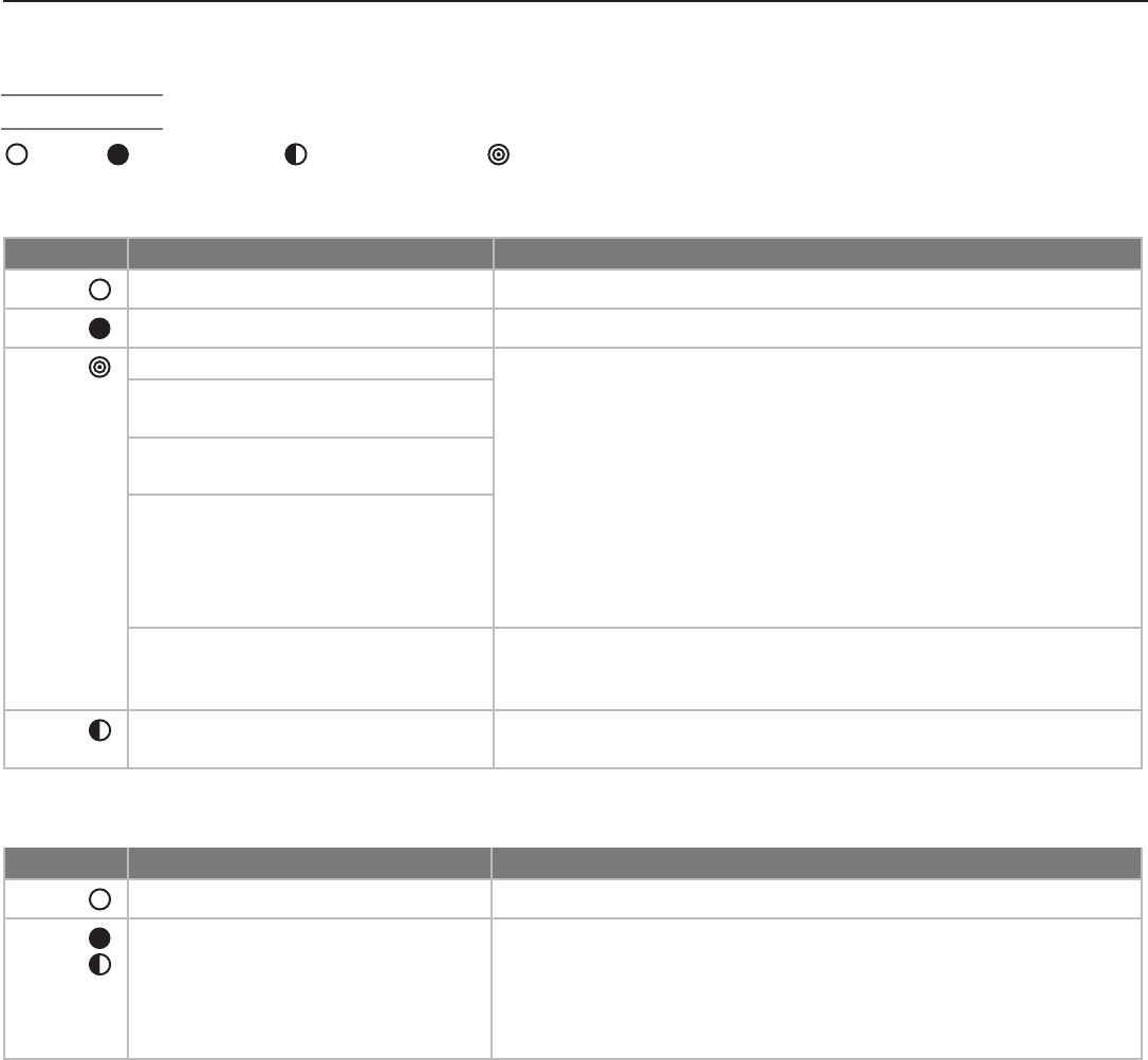
POWER/TIMER Indicator
LED Color TV Condition Additional Information
None TV is powered off. Normal operation.
Blue TV is powered on. Normal operation.
Blue 1. TV just plugged into AC outlet.
Wait until blinking stops before turning on (approximately 1
minute). Normal operation.
2. AC just restored after power
failure.
3. TV Rebooting after System
Reset used.
4. TV Rebooting after power
fluctuation or receiving abnor-
mal digital signals from digital
channel, CableCARD™, or
digital device.
5. You have begun the procedure
to update software from an
authorized flash memory device.
For detailed information, see the instructions that accompany the
authorized software update. Important: Do not use unauthorized
software at any time.
Blue TV powered off and auto-on timer
is set.
Normal operation. TV can be turned on at any time.
STATUS Indicator
LED Color TV Condition Additional Information
None Normal TV on or standby condition. Normal operation.
Red
TV may require service. Turn off the TV and unplug the set from the AC power source.
Wait one minute and then plug the set back in.
If the LED is still on, contact your dealer or a Mitsubishi Authorized
Service Center. See www.mitsubishi-tv.com or call 1-800-332-2119
to receive Authorized Service Center information.
Off Steady On Slow Blinking Fast Blinking
Chapter 1. Television Overview 17
CableCARD™ Technology
CableCARD is a nationwide system standard that allows
your local cable TV provider to supply you with an access
card customized to your account. This card allows your
TV to receive, decode, and unscramble the premium
digital channels included in your cable TV subscription
without the use of a cable box. When you move to a
new cable provider’s area, return the CableCARD to the
original cable provider and get a new card from your new
provider.
Please note that CableCARD is a relatively new technology
and your local cable provider may not currently be offer-
ing this service. As time passes, this system will become
broadly supported by most cable providers.
The CableCARD system is unidirectional, meaning your
cable provider can send updates to the TV, but the TV
cannot send signals back. As a result, certain advanced
and interactive digital cable services, such as requests for
video-on-demand and pay-per-view programs, a cable
operator’s enhanced program guide, and data-enhanced
television services may require use of a set-top box
instead. For more information, call your local cable opera-
tor.
Digital cable channels authorized by the CableCARD are
available on the Firewire® IEEE 1394 network and can be
shared by other products on the network. You may be
unable to record or copy some digital programs, however,
because of copy restrictions set by the content or copy-
right owners.
Using a CableCARD™
Power on the TV and insert the CableCARD into the
CableCARD slot with the top of the card oriented as indi-
cated by
CARD TOP .
When the initial screen dis-
plays, write down the information that appears and have it
ready when calling your cable provider.
In order to start cable
service for this device, please contact
your cable provider
1-800-xxx-xxxx
CableCARD(tm): xxx-xxx-xxx-xxx-xxx-x
Host: xxx-xxx-xxx-xxx-x
Data: xxx-xxx-xxx-xx
UnitAddress: xx-xxxxx-xxxxx-xxx
Press EXIT to exit.
Sample CableCARD initial screen. Record the information
before contacting your cable provider.
To review the information later, press
MENU
and when the
Main menu appears, press
9 9 9
to re-display the screen.
Note: CableCARD™ requires the TV’s Fast Power On
setting. If you insert a CableCARD™, the TV will
automatically override a Low Power setting and
change to the Fast Power On setting. IMPORTANT
To use a CableCARD, connect the primary
incoming cable to ANT 1/MAIN on the TV.
CableCARD™ Menu
Press ENTER to select an application. Press EXIT key to exit.
CableCARD menu
Network Setup
CableCARD(tm) Status
CableCARD(tm) Pairing
Conditional Access
Sample CableCARD menu
To display the CableCARD menu with links to applications
from your cable provider:
1. While watching CableCARD, press
INPUT
to open the
Input Selection menu.
2. With the CableCARD icon highlighted, press
MENU
to
open the CableCARD menu.
3. Press to highlight a link (blue text), then press
ENTER
to access the linked page.
4. To redisplay the CableCARD menu, repeat steps 1 and
2.
5. Press
EXIT
to return to TV viewing.
If there are technical problems with the CableCARD, an
error screen automatically displays with information that
may be needed by your cable provider when you call them
for assistance.
Moving Through Other CableCARD Screens
In addition to CableCARD menus, other CableCARD
application screens may display and require you to make
additional selections. When using these screens on your
Mitsubishi television:
• Blue text denotes a link to another screen. Press
ENTER
to move to the next application. Screens without blue
text contain no links.
• You cannot move backward through the links. To exit
the CableCARD system, press
EXIT
. The
CANCEL
key may
not work with some CableCARD screens.
All information on these application screens is provided by
your local cable company. Contact your cable provider if
you have any problems with the application screen displays.
IMPORTANT
Most CableCARD screens show only status or
diagnostic information and do not allow you
to make changes. These screens are mean-
ingful only to your local cable provider.
18 Chapter 1. Television Overview
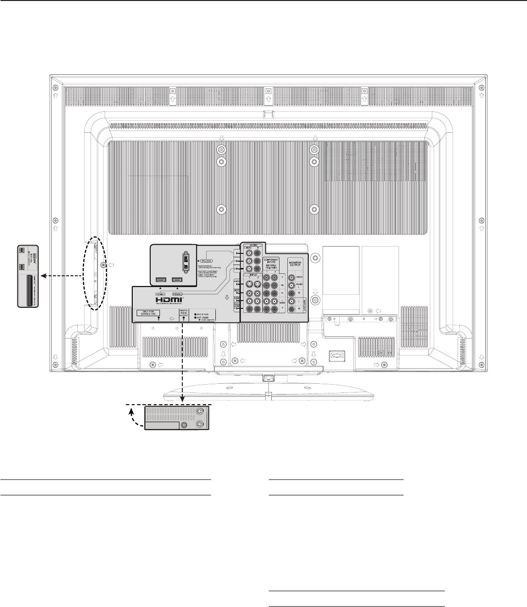
Back and Side Panels
2. INPUT 1 and 2 Inputs
(Audio and Video)
INPUT 1
and
2
can be used to connect a VCR, Super
VHS (S-VHS) VCR, DVD player, standard satellite receiver,
or other A/V device to the TV.
INPUT 3
is a third set
of jacks located in the front of the TV for convenience.
Please note that if
S-VIDEO
and
VIDEO
are both avail-
able, you must choose to connect only one.
3. COMPONENT 1 and 2 Inputs
(Audio and Video)
Y Pb Pr (480i/480p/720p/1080i)
Use these jacks to connect devices with component video
outputs, such as DVD players, external HDTV receivers, or
compatible video game systems. Please see Appendix B
for signal compatibility.
Back Panel 1
Back Panel 2
Side
Panel
1. ANT 1/MAIN, ANT 2/AUX ( Antenna)
If you are connecting an antenna, direct cable without
a cable box, or are using cable with a CableCARD™,
connect the main antenna or cable source to
ANT 1/MAIN
.
ANT 1/MAIN
and
ANT 2/AUX
can each receive both
digital and analog over-the-air channels from a VHF/UHF
antenna or non-scrambled digital/analog cable source.
ANT 1/MAIN and CableCARD™
Use
ANT 1/MAIN
to receive premium subscription
cable TV service authorized by the CableCARD™ access
card. The CableCARD access card is provided by your
local cable company.
ANT 2/AUX
can continue to
receive over-the-air or non-scrambled cable signals when
ANT 1
is used for CableCARD™ service.
Chapter 1. Television Overview 19
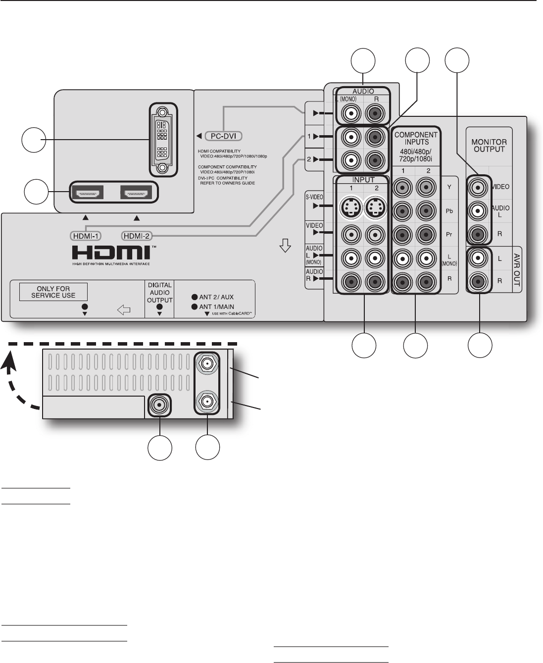
4. AVR OUT
(Audio only)
AVR OUT
(AUDIO/ViDEO RECEIVER OUT) L/R jacks
send analog audio of the program currently shown on
the screen to an A/V surround sound receiver or stereo
system. Digital audio from digital channels, FireWire®
(DTVLink/IEEE 1394) devices and HDMI devices is con-
verted to analog audio by the TV. If using an analog A/V
receiver or stereo system, this is the only audio connec-
tion needed between it and the TV.
5. MONITOR OUTPUT
Use these composite video and left/right audio jacks
to send analog video and audio signals to an external
recording device such as a VCR. The signals from these
jacks are from the program currently being viewed on the
TV screen. To make recordings from this output, the
TV must be in normal full-screen mode rather than in
Split-Screen mode.
• From this output you can record audio and video
signals from
ANT 1
,
ANT 2
,
INPUT 1-3
, and
IEEE 1394 devices.
• Digital signals from
ANT 1
,
ANT 2
, and IEEE
1394 devices are converted to analog video and
audio signals.
• Some signals cannot be recorded because of
copy-protection flags in the content.
• Video signals from devices connected to
COM-
PONENT 1 & 2
,
HDMI 1 & 2
or
PC DVI
are
not available from these
MONITOR OUTPUT
jacks.
6. HDMI/DVI AUDIO
Audio for HDMI 1 & 2: Use these analog audio inputs
when connecting DVI devices to the TV’s
HDMI
jacks.
Unlike HDMI, DVI does not carry audio information on the
same cable. For analog audio from a personal com-
puter, use the PC-DVI AUDIO jacks instead.
Back and Side Panels, continued
Back Panel 1
Back Panel 2
ANT 1/MAIN
(Located next to DIGITAL
AUDIO OUTPUT jack)
9
8
1
10
4
7
23
6 5
ANT 2/AUX
20 Chapter 1. Television Overview
Back and Side Panels, continued
7. PC-DVI AUDIO
Use the
PC-DVI AUDIO
jacks in conjunction with the
PC-DVI
video input from a personal computer. These
jacks allow you to send left and right analog audio from
your computer to the TV.
8. PC-DVI
PC-DVI
is a DVI-I input compatible with both DVI-A
(analog) and DVI-D (digital) inputs. Connect your personal
computer’s HDMI, DVI, or VGA video output to this jack. An
adapter or converter cable may be required.
Please see
Appendix B for signal compatibility. To hear audio from
the computer, connect analog audio cables from the com-
puter to the
PC-DVI AUDIO
jacks.
The PC-DVI input is not intended for standard video from
cable boxes, satellite receivers, or DVD players.
9. HDMI™ 1 and 2
The HDMI (High Definition Multimedia Interface) supports
uncompressed standard and high-definition digital video
formats and PCM digital audio format. For PC video, use
the
PC-DVI
input instead.
Do not connect a computer to either TV HDMI jack.
Use these inputs to connect to EIA/CEA-861 compliant
devices such as a high-definition receiver or DVD player.
These inputs support 480i, 480p, 720p, 1080i, and 1080p
video formats.
These inputs can also accept DVI video inputs. To connect
a DVI input, use an HDMI-to-DVI adapter or cable plus
analog audio cables. Connect the analog audio cables to
the
HDMI/DVI AUDIO
inputs on the TV to receive left
and right stereo audio from your DVI device.
These inputs are HDCP (High-Bandwidth Digital
Copy Protection) compliant.
These inputs are certified for proper
interoperability with other products certified by
Simplay™.
10. DIGITAL AUDIO OUT
This output sends Dolby Digital or PCM digital audio
to your digital A/V surround sound receiver. Analog
audio from analog channels and devices is con-
verted by the TV to PCM digital audio. If you have
a digital A/V receiver, in most cases this is the only
audio connection needed between the TV and your
A/V receiver.
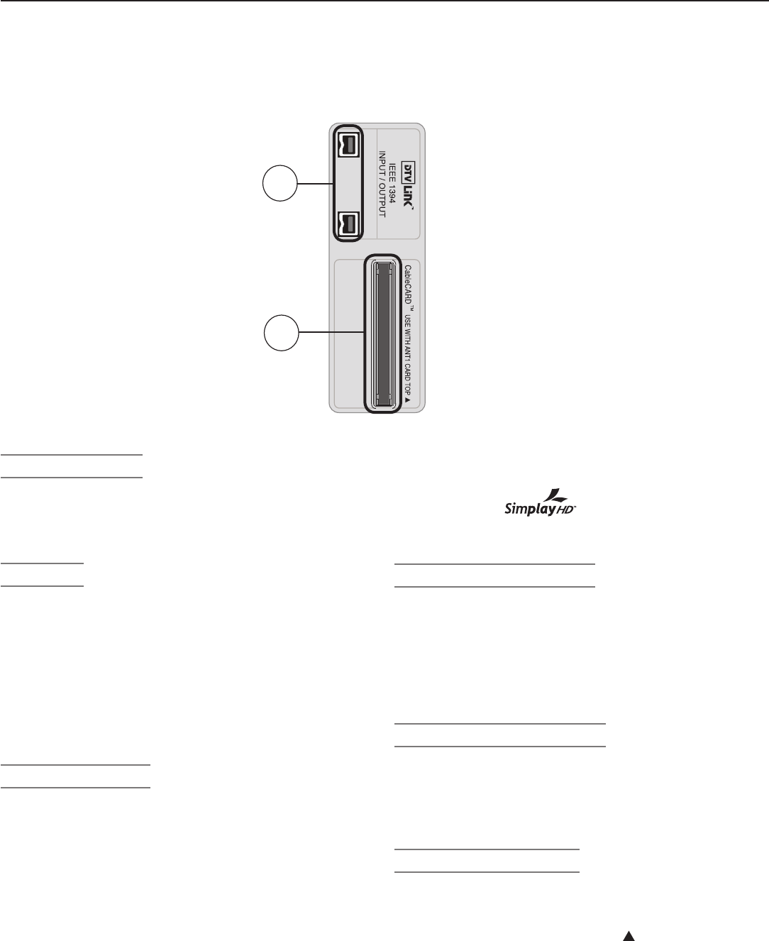
11. DTVLINK™/IEEE 1394
These jacks allow the TV to connect to external
IEEE 1394 digital products by means of a single
cable. See chapter 7, “Using IEEE 1394 Devices”
for detailed information regarding IEEE 1394 con-
nections and recording.
12. CableCARD™ Slot
The CableCARD access card from your cable TV
service provider is inserted into this slot. When
inserting, ensure that the top of the card faces in the
direction indicated by
CARD TOP
.
If your cable company is not currently offering
CableCARD access cards, use the cable box pro-
vided and authorized by your local cable company to
view scrambled channels.
11
Side Panel
12

2
TV Connections
Before You Begin
Choosing a Language for Menus . . . . . . . . . . . . . . . . . . . . . . . . . . 22
ClearThought® Easy Connect Auto Input Sensing . . . . . . . . . . . . . . . 22
Digital Video and Home Recording . . . . . . . . . . . . . . . . . . . . . . . . 23
Connection Types ................................... 24
Cable Management .................................. 25
HDTV Cable Box or Satellite Receiver with Component Video .... 26
Standard Cable Box, Satellite Receiver, or Other Device
with S-Video .................................... 26
Wall Outlet Cable (no cable box) ......................... 27
Antenna with a Single Lead ............................ 28
Antennas with Separate UHF and VHF Leads ................ 28
VCR to an Antenna or Wall Outlet Cable ................... 29
VCR to a Cable Box (Audio & Video) ...................... 30
H
DMI Device (Cable Box, Satellite Receiver, DVD Player,
or Other Device) .................................... 31
DVI Video Device (Cable Box, Satellite Receiver, DVD Player,
or Other Device) .................................. 31
DVD Player with Component Video ....................... 32
A/V Receiver (Stereo System) .......................... 32
Older Cable Box .................................... 33
Camcorder ........................................ 33
22 Chapter 2. TV Connections
Before You Begin
Choosing a Language for Menus
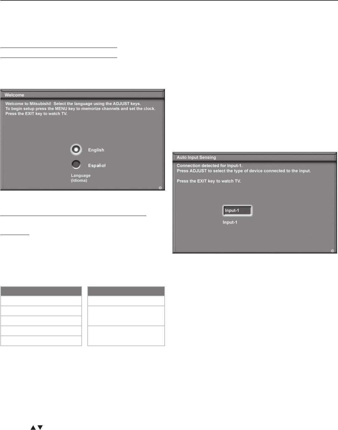
When you power on the TV for the first time, you can
select either English or Spanish for all menus. You can
later change the language through the Setup menu.
Figure 1. The Welcome screen lets you change the menu
language when you first power on the TV.
ClearThought® Easy Connect Auto Input
Sensing
This TV’s ClearThought® auto input sensing feature
allows it to detect most connections automatically. The
first time you connect each device you will be prompted
to identify it by selecting from a pre-set list of device
names. The table below defines how connections on
each TV jack are handled.
Auto Detection Active No Auto Detection
INPUT
1
,
2
,
3
video jacks
ANT 1/ANT 2
COMPONENT video jacks
MONITOR OUTPUT
(all jacks)
HDMI
*
PC-DVI
*All
AUDIO
jacks
IEEE 1394
* If the device is powered off when connected, detec-
tion occurs when the device is next powered on.
1. Connect your devices to the TV, making note of which
TV input you have used for each device.
The TV and the devices can be either on or off when
connecting. If the TV is powered off, the detection
process will occur the next time you turn on the TV.
2. For most devices, the Auto Input Sensing screen
opens (see figure 2). With the text box highlighted,
press to select a name for the device from the
following list of names:
Cablebox
Camcorder
DVD
DVD2
DVR (digital video recorder, recordable DVD)
Game
HD Disc (high-definition disc)
Satellite
VCR
The name you assign here will appear in the Input
Selection menu and can be changed later through the
Input Name menu.
3. Press
EXIT
to close the screen. If you connected
several devices at the same time, the screen for the
next connection will open.
Figure 2. The Auto Input Sensing screen appears when a
device is first detected. Select a name for the connected
device in this screen.
More About Auto Input Sensing
• You can change the input name at a later time using
the Input Name menu.
• If you disconnect a device and then later connect a
different device to the unused jack, open the Input
Name menu to update the device name.
• Antenna inputs (
ANT 1/ANT 2)
and TV outputs are
never auto-detected.
• Be careful to choose different names for each input.
IEEE 1394 Connections
The screen in figure 3 appears when you make an IEEE
1394 connection,
IEEE 1394 Device with an Analog Connection.
Some IEEE 1394 devices have both digital and analog
outputs to the TV. If you have such a device, place a
check mark in the Analog Connection check box to:
• Allow a cable box with both analog and digital outputs
to switch automatically between them.
Chapter 2. TV Connections 23
• Allow you to use a TV menu to select either the analog
or digital output from the device.
For instructions on switching between analog and digital
outputs, see chapter 7, “Using IEEE 1394 Devices.”
Name assigned
to the device
Figure 3. The ClearThought Auto Input Sensing screen for
IEEE 1394 devices includes a check box for an associated
analog connection.
If your IEEE 1394 device has an analog connection to the
TV, follow the instructions below.
1. Connect the device to the TV with an IEEE 1394 cable
first.
2.
When the New 1394 Device screen appears with the
Analog Connection check box highlighted, press
ENTER
to
enter a check mark. See figure 3, New 1394 Device screen.
Digital Video and Home Recording
The table below will help you decide which type of connection to use for digital video. Digital video comes to your
home in a compressed state, whether received on recorded media (e.g., disc) or broadcast over the air, over cable, or
via satellite. Some compressed digital video is available for recording as noted in the table.
Connection Type into the TV
Effect on Home Recording
HDMI or DVI
Compressed video is converted to
uncompressed form by an external device
such as a cable box, satellite receiver, or
DVD player before it is sent to the TV on an
HDMI or DVI cable.
You cannot record the resultant uncompressed video sent to the TV
via HDMI or DVI.
IEEE 1394 (FireWire®) Connections
Your TV can receive and decode digital
channels, MPEG2 compressed digital video,
and Dolby Digital audio.
You can record compressed digital video either
• on compatible digital recorders as digital signals
• as standard-definition composite video from the
MONITOR
OUTPUT
jack converted to analog signals
You may be unable to record some programming because of copy restric-
tions added by the content owners.
Note: It is important to check mark the box when
this screen appears upon first connecting the device,
as later changes can only be made after returning all TV
settings to their defaults.
3. In the New 1394 Device screen, note the name
assigned to the device, as you will need to use the
same name in a later step. See figure 3.
4. Connect the device to the TV with the supplemental
analog cables.
5. The next screen is the Auto Input Sensing screen
(see figure 2) in which you can select a name for the
device. Select the same name you noted in the New
1394 Device screen (see figure 3).
• If you select the wrong name for the device, you will
be unable to switch between the analog and digital
inputs to the TV.
• If you connect an IEEE 1394 cable box and it is
detected as CABLE in the New 1394 Device screen,
be sure to select the name CABLE as the name for the
analog input and not cablebox.
To Add an Analog Connection at a Later Time (not
recommended)
1. Disconnect the IEEE 1394 device from the TV.
2. Reset all TV settings to their defaults using the TV
Reset service menu as follows:
a. Press
MENU
to display the Main menu.
b. Press
1 2 3
to open the Reset service menu.
c. Press
ENTER
.
3. Reconnect the IEEE 1394 device to the TV.
4. When the TV recognizes the device, place a check in
the Analog Connection check box.
5. Press
EXIT
.
Before You Begin, continued
24 Chapter 2. TV Connections
Connection Types
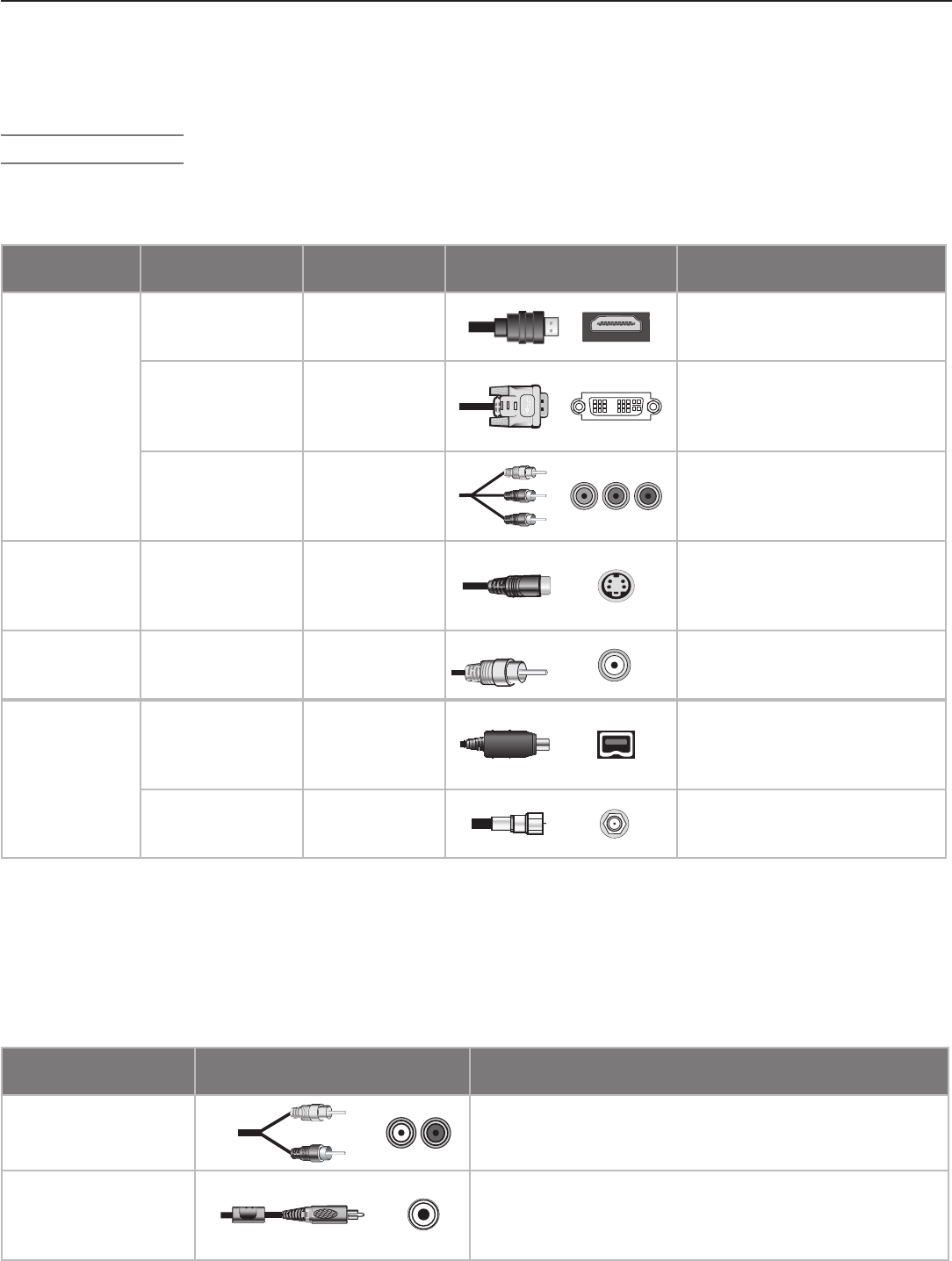
Video and Combined Audio/Video Connections
These descriptions apply to TV video only and do not cover signals from personal computers.
Picture Quality
(most sources) Name Signal Type Figures
(not to scale) Additional Information
Best
(carry high-
definition video
when available)
HDMI Digital audio
and video
Carries digital audio and
uncompressed digital video on
a single one-way cable.
DVI
Digital video
Carries uncompressed digital
video alone on a single one-way
cable; requires separate audio
connections.
Component Video
Analog video
Carries analog high-definition
and standard-definition signals.
Y Pb Pr RCA-style connectors
are colored green, blue, and red.
Good S -Video
Analog video
Carries analog standard-defini-
tion signals.
Provides better
quality video than composite or
RF coaxial video.
Fair Composite Video
Analog video
Carries analog standard-defini-
tion signals.
RCA-style connec-
tor, usually colored yellow
Fair to Best
(depending on
source; carry
all qualities of
signals)
IEEE 1394
(FireWire®)
Digital audio
and video
Carries compressed digital
video and audio as well as
device control signals on a
single two-way cable.
RF Coaxial Video
Analog and
digital audio
and video
Carries audio and video on a
single cable.
Note: Only some TV signals are high-defi nition signals. To view high-defi nition programming from your cable or satel-
lite provider, you must subscribe to the provider’s high-defi nition service. Some over-the-air broadcasts are in
high-defi nition and can be received with a high-quality antenna suited to your location.
Audio-Only Connections
There are two types of audio connections used on this TV. Refer to the table below.
Audio Connection Figures
(not to scale) Additional Information
Left/Right Analog
Stereo Audio
RCA-style connectors usually colored white for left and
red for right stereo audio. For monaural sound (all speak-
ers playing the same sound), use only the white connector.
Digital Audio (Coaxial)
RCA-style connector usually colored orange. Use to send
digital audio from the TV to your digital A/V receiver for
surround-sound effects. Usually the only audio connec-
tion required between the TV and the A/V receiver.
Before You Begin, continued
Chapter 2. TV Connections 25
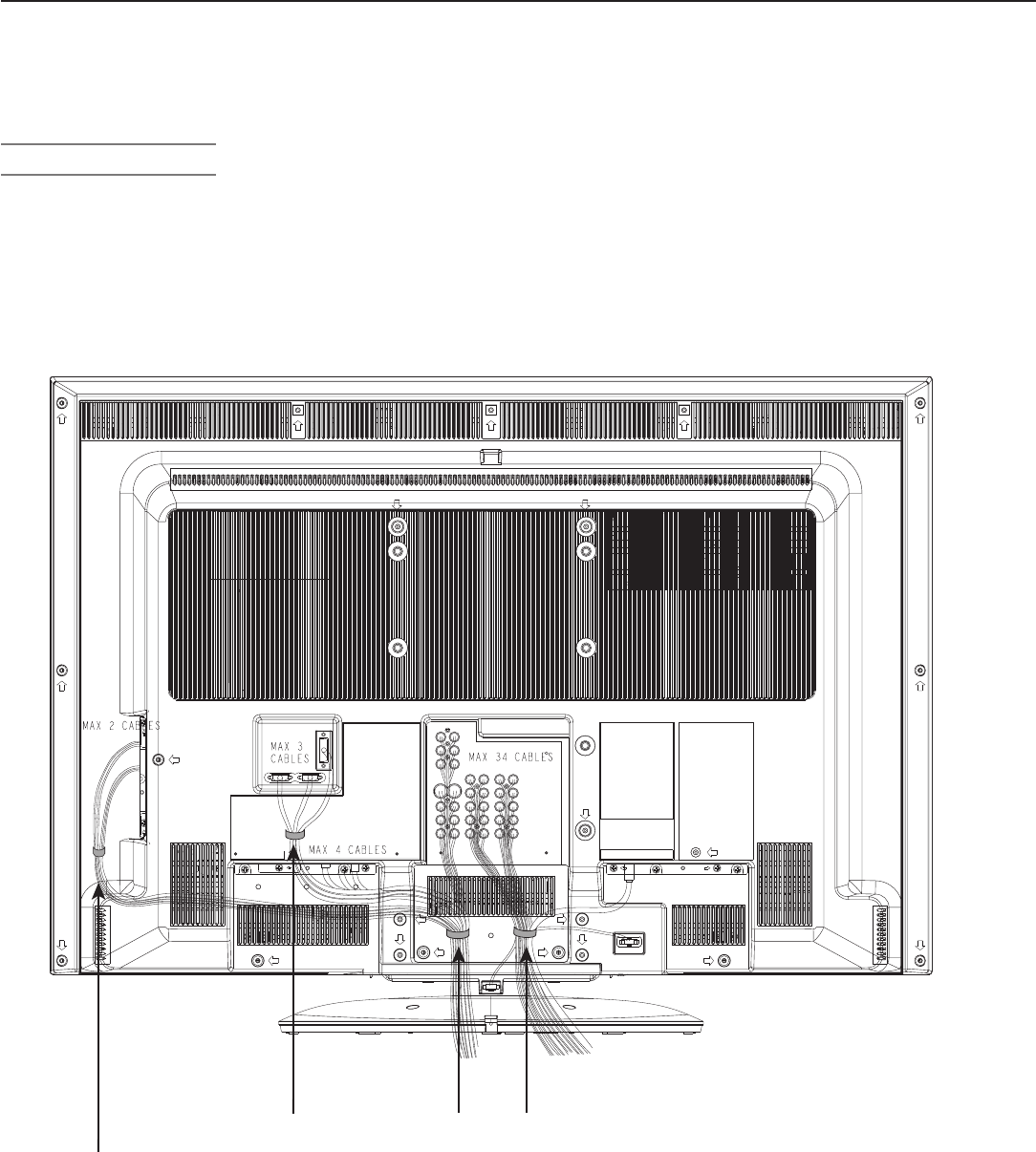
Cable Management
Both TV models provide cable ties that help keep cables
properly organized and connected, especially important
when the swivel feature is used. For more information
about the swivel feature, see Manual and Power Swivel in
Chapter 1.
Before You Begin, continued
Cable ties #1-3 come attached to the back of the TV, and
cable tie #4 is provided with the accessories and must be
attached by TV owner. The number of cables that are con-
nected to the TV will determine the number of cable ties
that will be needed.
26 Chapter 2. TV Connections
H DTV Cable Box or Satellite
Receiver with Component Video
If your cable box or satellite receiver has HDMI or DVI
outputs, use the connections for HDMI or DVI video
devices described later in this chapter.
Required: RCA component video cables, left/right
analog audio cables.
A coaxial splitter, available at most electronic supply
stores, may be required to complete this installation.
1. Connect the cable from the outside cable or satel-
lite service to
CABLE IN
or
SATELLITE IN
on
the cable box or satellite receiver. See your device’s
owner’s guide for instructions and cable compatibility.
Figure 4. Connecting an external HDTV receiver with
component video connections
2. Connect RCA-type cables from the Y Pb Pr outputs
on the HDTV cable box or satellite receiver to
COM-
PONENT
on the TV back panel, matching the red,
green and blue-colored connections.
3. Connect left (white) and right (red) audio cables from
the HDTV cable box or satellite receiver to
COMPO-
NENT
/
AUDIO LEFT
and
AUDIO RIGHT
on the
TV back panel.
4. Optional: To allow use of the Split Screen feature
with channels from
ANT 1
and the cable box or
satellite receiver, connect the incoming terrestrial
antenna or cable service (not satellite) to
ANT
1/MAIN
on the TV back panel. A coaxial splitter,
available at most electronics supply stores, may be
required to complete this installation.
Note: T
o receive the benefi ts of digital surround sound, con-
nect the digital audio output from your cable box or
satellite receiver directly to your digital A/V receiver.
Standard Cable Box, Satellite
Receiver, or Other Device with
S-Video
Required: S-Video cable and left/right analog stereo
audio cables.
1. Connect the cable from the outside cable or satellite
service to
CABLE IN
or
SATELLITE IN
on the
cable box or satellite receiver.
2. Connect an S-Video cable from
VIDEO OUT
on the
cable box or satellite receiver back panel to
INPUT
S-VIDEO
on the TV back panel.
3. Connect left (white) and right (red) audio cables from
AUDIO OUT
on the cable box or satellite receiver to
INPUT/AUDIO LEFT
and
AUDIO RIGHT
on the
TV back panel.
Note: Refer to the cable box or satellite receiver Owner’s
Guide for cable or dish antenna connections to the
receiver.
Figure 5. Connecting a device with S-Video
Chapter 2. TV Connections 27
Wall Outlet Cable (no cable box)
(can be used with a CableCARD™)
It is very important to connect the incoming cable for your
primary viewing source to
ANT 1/MAIN
, especially for
CableCARD™ use.
1. Connect the primary incoming coaxial lead cable to
ANT 1/MAIN
on the TV back panel.
2. For an optional secondary antenna source, connect
an antenna (or cable) to
ANT 2/AUX
.
3. If you have subscribed to a CableCARD™ service,
Insert the CableCARD into the CableCARD slot. The
top of the card must face in the direction indicated by
the
CARD TOP
arrow.
See chapter 1, “Television Overview,” for additional
CableCARD information.
Figure 6. Wall Outlet Cable
Note: ANT 1 is located behind ANT2 when you are
facing the back of the TV.
28 Chapter 2. TV Connections
Antennas with Separate UHF and
VHF Leads
Required: UHF/VHF combiner
This is not included with the TV, but is available at most
electronics stores.
1. Connect the UHF and VHF antenna leads to the UHF/
VHF combiner.
2. Push the combiner onto
ANT 1/MAIN
on the TV
back panel.
Figure 8. Connecting separate UHF and VHF Antennas
Note: ANT 1 is located behind ANT 2 when you are facing
the back of the TV.
Mitsubishi strongly recommends you avoid using
antennas with flat twin leads. Flat twin lead
antenna wires are subject to interference which
may adversely affect the performance of the TV.
We recommend using coaxial antenna cable.
Antenna with a Single Lead
A. For an antenna with flat twin leads
A 300-ohm-to-75-ohm transformer is required. This is not
included with the TV, but is available at most electronics
stores.
A1. For an antenna with flat twin leads, connect the 300-
ohm twin leads to the 300-ohm-to-75-ohm trans-
former.
A2. Push the 75-ohm side of the transformer onto
ANT 1
on the TV back panel.
B. For cable or antenna with coaxial lead
Connect the coaxial lead directly to
ANT 1
on the TV
back panel.
Figure 7. Connecting a Single Antenna
Note: ANT 1 is located behind ANT 2 when you are facing
the back of the TV.
Chapter 2. TV Connections 29
VCR to an Antenna or Wall Outlet
Cable
Required: Two-way RF splitter, 3 coaxial cables, right and
left analog audio cables, either S-video or video cable.
These are not included with the TV but are available at
most electronics stores.
1. Connect the incoming cable or antenna to
IN
on the
RF splitter.
2. Connect one coaxial cable from
OUT
on the RF split-
ter to
ANTENNA IN
on the VCR back panel.
3. Connect one coaxial cable from
OUT
on the RF split-
ter to
ANT 1/MAIN
on the TV back panel.
4. To use the TV speakers with the VCR, connect left
(white) and right (red) audio cables from
AUDIO
OUT
on the VCR to
INPUT/AUDIO LEFT
and
AUDIO RIGHT
on the TV back panel. If your VCR is
mono (non-stereo), connect only the white (left) cable.
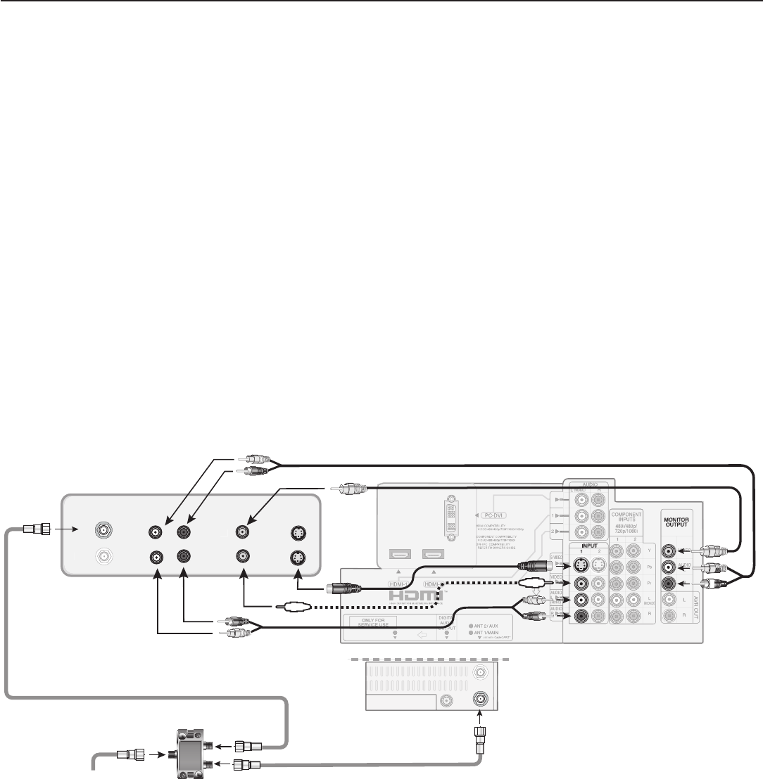
Figure 9. Connecting a VCR to an Antenna or Wall Outlet Cable
Note: ANT 1 is next to the DIGITAL AUDIO OUTPUT jack.
5. Connect either an S-Video or composite video
cable from
VIDEO OUT
on the VCR back panel to
INPUT/VIDEO
or
S-VIDEO
on the TV back panel.
Connect only one type of video cable; S-Video is
recommended, if available.
Optional
To record high-definition digital channels converted
to analog standard-definition video and analog stereo
audio, perform these two additional steps.
6. Connect left (white) and right (red) audio cables from
AUDIO IN
on the VCR to
MONITOR OUTPUT
LEFT
/
RIGHT
on the TV back panel. If your VCR
is mono (non-stereo), connect only the white (left)
cable.
7. Connect a composite video cable from
VIDEO IN
on the VCR back panel to
MONITOR OUTPUT/
VIDEO
on the TV back panel.
30 Chapter 2. TV Connections
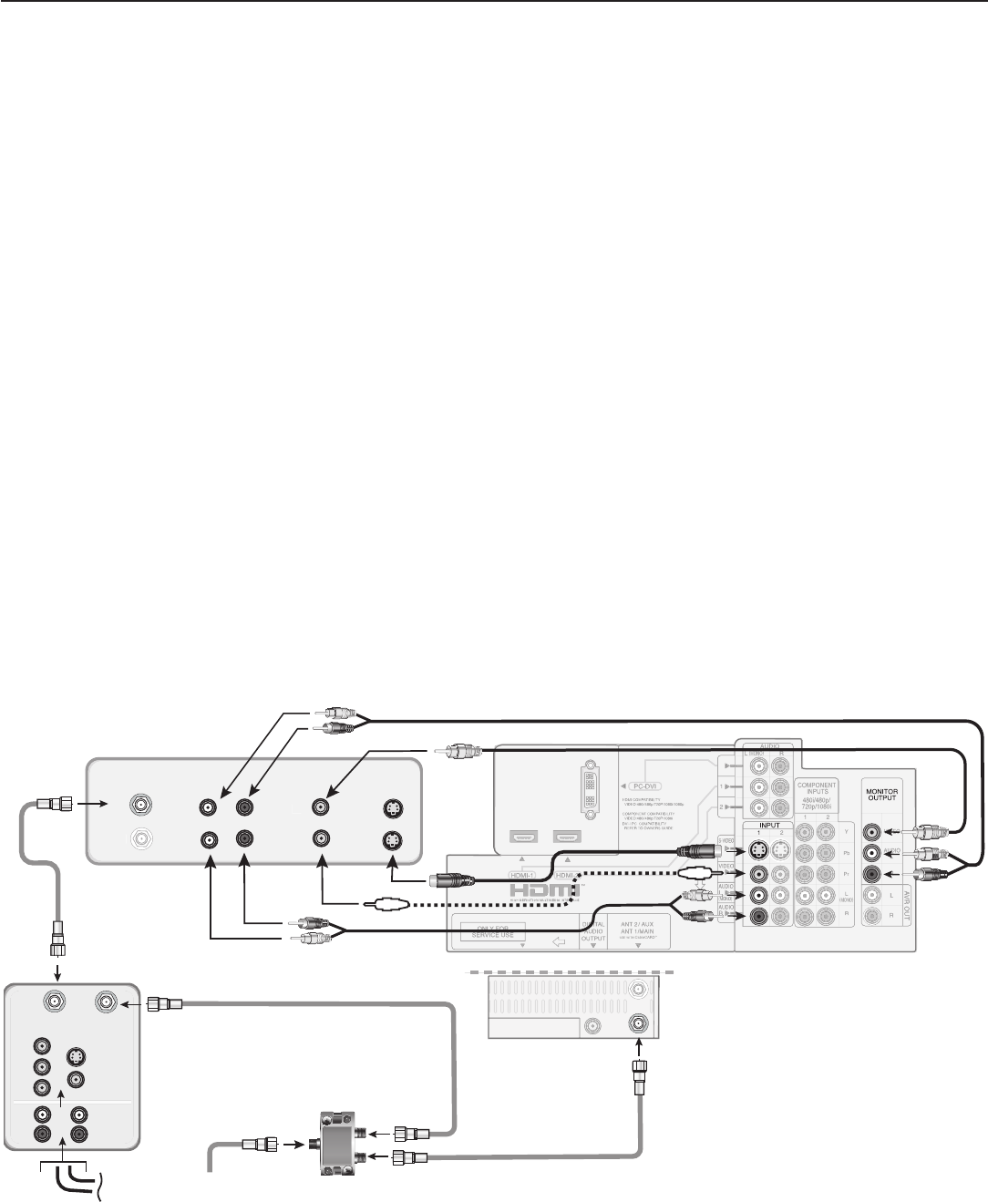
VCR to a Cable Box (Audio & Video)
Required: Two-way RF splitter, 4 coaxial cables, right and
left audio cables, S-Video or composite video cable, plus
component or S-Video cables and audio cables required
to connect the TV to the cable box.
1. Connect the incoming cable to
IN
on the RF splitter.
2. Connect one coaxial cable from
OUT
on the RF split-
ter to
CABLE IN
on the cable box.
3. Connect one coaxial cable from
OUT
on the RF split-
ter to
ANT 1/MAIN
on the TV back panel.
4. Connect one coaxial cable from
OUT
on the cable
box to
ANTENNA IN
on the VCR back panel.
5. Connect the cable box outputs to the TV as shown in
either figure 4 or figure 5, earlier in this chapter. This
connection allows the TV to receive the best available
signal directly from the cable box.
Figure 4: Component video output to the TV’s
COMPONENT Y Pb Pr
jacks; analog stereo
audio to the associated
AUDIO
jacks.
Figure 5: S-Video output to the TV’s
INPUT/S-VIDEO
jack; analog stereo audio to
the associated
AUDIO
jacks.
6. To use the TV speakers with the VCR, connect left
(white) and right (red) audio cables from
AUDIO
Figure 10. Connecting a VCR to a cable box
Note: ANT 1 is next to the DIGITAL AUDIO OUTPUT jack.
OUT
on the VCR back panel to
INPUT/AUDIO
LEFT
and
AUDIO RIGHT
on the TV back panel.
If your VCR is mono (non-stereo), connect only the
white (left) cable.
7. Connect either an S-Video or composite video
cable from
VIDEO OUT
on the VCR back panel to
INPUT/VIDEO
or
INPUT/S-VIDEO
on the TV
back panel. Connect only one type of video cable. S-
Video is recommended, if available.
Optional
8. To allow recording from the TV to the VCR:
a. Connect left (white) and right (red) audio cables
from
AUDIO IN
on the VCR back panel to
MONITOR OUTPUT/LEFT
and
RIGHT
on
the TV back panel.
b. Connect a video cable from
VIDEO IN
on
the
VCR back panel to
MONITOR OUTPUT/
VIDEO
on the TV back panel.
Note: When using this connection confi guration with the
connections used in step 5, it is possible to view
live cable programs through the VCR Device. For
best picture quality always view live cable pro-
grams directly from the cable box device.
Chapter 2. TV Connections 31
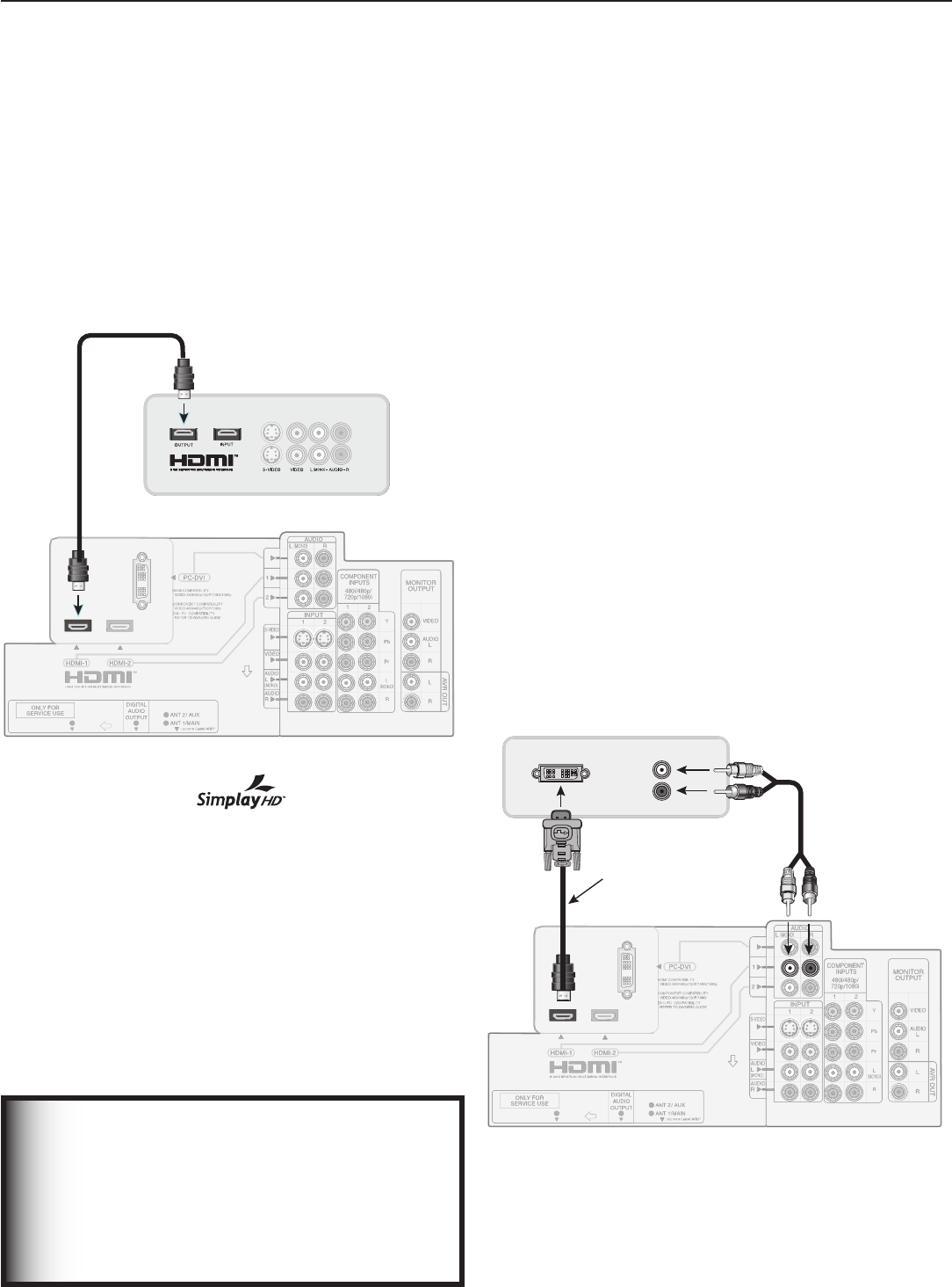
DVI Video Device (Cable Box,
Satellite Receiver, DVD Player, or
Other Device)
Analog stereo audio cables and a DVI-to-HDMI cable or
DVI/HDMI adapter and HDMI cable are required. These
are not included with the TV. They may be available at
your local electronics retailer.
1. Connect the DVI-to-HDMI cable (recommended) or
HDMI cable with DVI/HDMI adapter from the DVI
device’s back panel to the TV back panel.
NOTE: If you are using a DVI/HDMI adapter, it is impor-
tant to connect the adapter to the DVI device for
best performance.
2. Connect a set of audio cables from
AUDIO OUT
on the DVI device back panel to the
HDMI/DVI
AUDIO
on the TV back panel. Connect the red
cable to the
RIGHT
jack and the white cable to the
LEFT
jack.
NOTE: The HDMI connection supports copy protection
(HDCP).
Some devices require connecting to an analog
input fi rst, in order to view on-screen menus and
to select DVI as the ouput. Please review your
equipment instructions for DVI connectivity and
compatibility.
Figure 12. Connecting a DVI device
H
DMI Device (Cable Box, Satellite
Receiver, DVD Player, or Other Device)
Required: HDMI-to-HDMI cable. This is not included
with the TV.
Connect an HDMI cable from the TV back panel to the
HDMI device output. HDMI devices provide video and
audio through this cable, so no other connection is
required. You can connect two HDMI devices to the TV
back panel through the HDMI connections.
Figure 11. Connecting an HDMI device.
Note:
HDMI inputs are certifi ed for proper
interoperability with other products certifi ed by Sim-
play™.
IMPORTANT
To connect a personal computer to the TV,
see chapter 6, “Using the TV with a Personal
Computer.”
The HDMI input processes signals as standard
motion video and is not designed to process
computer resolutions.
32 Chapter 2. TV Connections
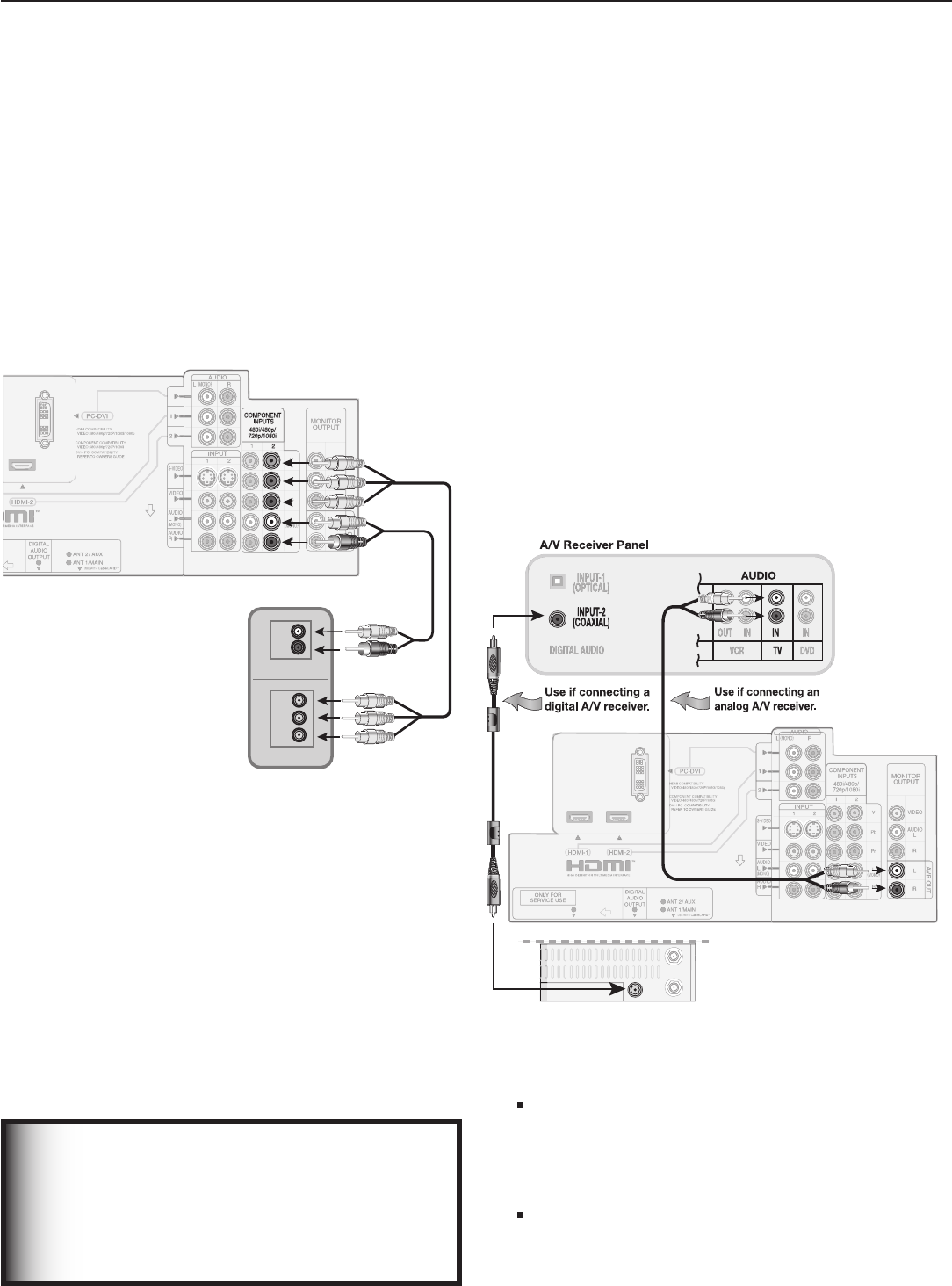
DVD Player with Component Video
Component video cables and analog audio cables are
required. These are not included with the TV.
1. Connect the component video cables from
Y PB PR
VIDEO OUT
on the back of the DVD player to the
COMPONENT
jacks on the TV back panel, match-
ing the red, green, and blue colored connections.
2. Connect left (white) and right (red) stereo audio
cables from
AUDIO OUT
on the back of the DVD
player to
COMPONENT/AUDIO LEFT
and
RIGHT
on the TV back panel.
Figure 13. Connecting a DVD player with component video
IMPORTANT
See Appendix B for component video signal
compatibility information.
For digital audio connections to your
A/V receiver, see your DVD player and A/V
receiver Owner’s Guides.
A/V Receiver (Stereo System)
Most setups require either a digital audio cable or analog
stereo audio cables.
The TV makes all audio available in digital and analog
formats. Analog audio coming into the TV is available
in digital format on the
DIGITAL AUDIO OUT
jack.
Digital incoming audio is available in analog format on the
AUDIO OUT LEFT/RIGHT
jacks. Usually, only one of
the following connections is required:
• To connect an analog A/V receiver
Connect left (white) and right (red) audio cables from
AVR OUT/LEFT
and
RIGHT
on the TV back panel
to the
TV AUDIO INPUT
on the A/V receiver.
• To connect a digital A/V receiver with Dolby
Digital surround sound and PCM audio support
Connect one end of the digital audio cable to
DIGITAL AUDIO OUT
on the back of the TV.
Connect the other end to the
COAXIAL DIGITAL
INPUT
on the back of the A/V receiver.
Figure 14. Connecting audio from the TV to an A/V receiver
Note:
On rare occasions, an HDMI signal may be
copy-restricted and cannot be output from the TV
as a digital signal. To hear these copy-protected
signals through the A/V receiver, use connections
for analog A/V receivers.
Check the A/V receiver’s Owner’s Guide for
information concerning use of the digital input
and switching between digital sound and analog
stereo sound from the TV.
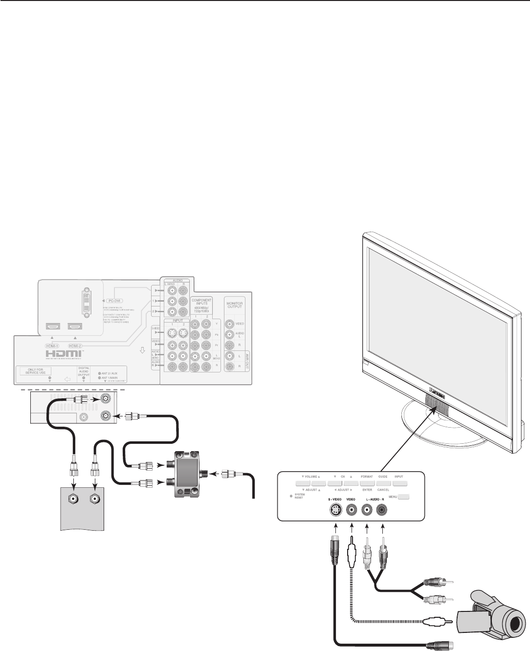
Chapter 2. TV Connections 33
Older Cable Box
Required: 3 coaxial cables, one two-way RF splitter.
These are not included with the TV.
When this setup is complete, you can use the TV remote
control, when programmed, to change channels on the
cable box.
Note: This connection is not recommended. The other
connections described in this chapter provide bet-
ter quality audio and video to the TV.
1. Connect the incoming cable to
IN
on the RF splitter.
2. Connect one coaxial cable from
OUT
on the RF split-
ter to
ANT 1/MAIN
on the TV back panel.
3. Connect one coaxial cable from
OUT
on the RF split-
ter to
IN
on the standard cable box.
4. Connect one coaxial cable from
OUT
on the cable
box to
ANT 2/AUX
on the TV back panel.
Figure 15. Connecting an older cable box
Note: ANT 1 is located behind ANT 2 when you are facing
the back of the TV.
Camcorder
Required: Analog stereo audio cables and either an S-
Video or composite video cable.
NOTE: For IEEE 1394 camcorders, see also chapter 7,
“Using IEEE 1394 Devices.”
1. Connect either an S-Video or composite video cable
from
VIDEO OUT
on the camcorder to
INPUT
3/VIDEO
or
S-VIDEO
on the TV. Connect only one
type of video cable; S-Video is recommended, if avail-
able.
2. Connect left (white) and right (red) audio cables from
AUDIO OUT
on the camcorder to
INPUT 3/
AUDIO L
and
AUDIO R
on the TV.
Figure 16. Analog connections for a camcorder

34 Chapter 2. TV Connections

TV Operation
Remote Control .................................... 36
Choosing a Program Source ........................... 38
ChannelView™ Channel Listings ........................ 38
Status Display ..................................... 39
TV Signals and Display Formats ......................... 40
Split Screen ....................................... 42
3
36 Chapter 3. TV Operation
Remote Control
Overview
See Figure 1, next page
1. Slide Switch: Selects the A/V device to be controlled
by the remote control. Set the slide switch to
TV
for
operation of the TV and IEEE 1394 devices. Control of
other device types requires programing (see chapter
3, “TV Operation”).
2.
SLEEP
: Sets the TV to turn off within 2 hours. See the
next page for instructions.
3. Digits/Letters: Allow you to tune to a channel by
entering channel numbers; press
ENTER
for faster
tuning. Use numbers and the
CANCEL
key to enter digital
sub-channels. Also use for entering information into
menus.
To select letters when naming channels, repeatedly
press the associated number key. The following
special characters are available with the
1
and
0
keys:
1
! & blank space
0
/ * -
4.
—/CANCEL (SUB-CHANNEL/CANCEL)
: When entering digital
channel numbers, adds a separator between main
and sub-channel numbers. Clears FAV and some
menu entries.
5.
POWER
: Turns TV power on and off.
6.
QV (QuickView™): Switches between the current
channel and the last channel viewed. This only applies
to channels received from ANT 1 and ANT 2 jacks.
7.
MUTE
: Turns TV sound off or on.
8.
SPLIT
: Turns Split Screen mode on and off.
9.
VOL
/ (Volume Up/Down): Changes sound level.
10.
CH/PAGE
/ (Channel or Page Up/Down): Scans
up or down through memorized channels. Pages
up and down through screens when used with
ChannelView™.
11
FAV
(Favorites): Scans through memorized lists of
favorite channels. See “Channel Menu” in chapter 4,
“TV Menu Settings,” for more information.
12.
FORMAT
: Changes the shape and size of the main TV
picture. When in Split Screen mode, changes the
size of the split images while maintaining their aspect
ratios.
13.
INPUT
: Displays the Input Selection menu from which
you can select an input source to view, such as an
antenna input (
ANT 1
/
2
) or a connected device.
Note: To operate other audio/video devices:
• See chapter 5, “Programming the Remote Control”
for instructions on programming.
• For control of IEEE 1394 devices, see chapter 7.
14. (Adjust Up/down/Left/Right): Navigate
menus and change settings.
(Power) Swivel — LT-37131 model only: With no
menu or slider displayed, swivels the TV thirty degrees
left or right. Swivel is not available in Split Screen mode.
15.
ENTER
: Selects a channel number or menu item.
16.
GUIDE
: Displays or removes ChannelView™ on-screen
channel listing for
ANT 1
and
ANT 2
.
17.
INFO
: Displays an on-screen summary of the current
device in use and any broadcast information available,
including current V-Chip information. See chapter 3,
“TV Operation,” for details.
18.
AUDIO
: Selects individual audio settings for adjustment.
19.
VIDEO
: Selects individual video settings for adjustment,
including
Swivel (LT-37131 only; see item #14.)
20.
MENU
: Displays the main TV menu using the
on-screen menu system. When a sub-menu is open,
backs up one level.
21.
EXIT:
Closes all TV on-screen menus and displays and
returns to normal TV viewing.
22.
F1–F4
: When programmed, work like the A, B, C, D
buttons on some cable boxes and satellite receivers.
Program the remote control for your equipment and
test the keys. See chapter 5, “Operating Other A/V
Devices with the Remote Control.”
24. (
PAUSE
): Freezes a broadcast TV picture when no
Split Screen image is displayed. When Split Screen is
displayed, freezes the sub-picture. See below for use
with recordable media.
Record/Playback Keys
To enable the recording and playback functions, program
the remote for your VCR or DVD player/recorder and set
the slide switch to
VCR
or
DVD
. See chapter 5 for instruc-
tions on programming the remote. If you have an IEEE
1394 device, see chapter 7 on IEEE 1394 devices.
23. (
RECORD
): Records with a VCR, DVR, or DVD
recorder.
24. (
PAUSE
): Pauses a VCR, DVR or DVD. See above
for use during TV viewing.
25. (
STOP
): Stops play of a VCR, DVR, or DVD.
26. (
REVERSE
): Rewinds a VCR. Reverse scans a DVR
or DVD.
27. (
PLAY
): Plays a VCR, DVR, or DVD.
28. (
FAST FORWARD
): Fast forwards a VCR. Forward
scans a DVD or DVR.
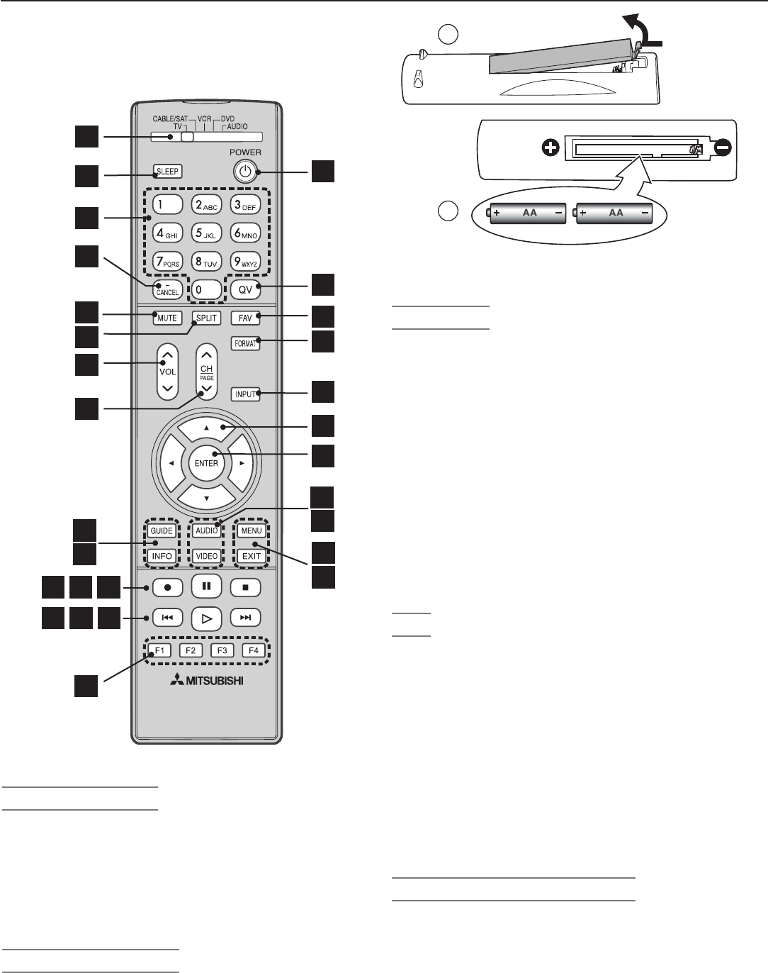
Chapter 3. TV Operation 37
22
28
10
1
2
3
4
7
8
9
2423
26 27
25
16
17
11
12
13
14
15
5
6
18
19
20
21
Figure 1. Remote Control Overview
Battery Installation
1. Remove the remote control’s back cover by gently
pressing in the tab and lifting off the cover (Figure 2).
2.
Load the batteries, making sure the (+) and (-) polarities
are correct. For best results, insert the negative (-) end
first.
3. Snap the cover back in place.
Low Battery Indicator
If the
POWER
button blinks five times after you have pressed
any button, the remote control batteries are low and should
be replaced.
2
1
Figure 2. The remote control requires two AA alkaline
batteries.
Sleep Timer
Setting the Sleep Timer
1. Press
SLEEP
on the remote control.
2. Press
SLEEP
additional times to increase the time in 30-
minute increments up to the maximum of 120 minutes.
3. Press
EXIT
or wait five seconds without pressing any
buttons for the message to disappear.
4. Press
SLEEP
to view the time remaining before the sleep
timer turns off the TV.
Cancelling the Sleep Timer
1. Press
SLEEP
to display the on-screen message.
2. Press
SLEEP
repeatedly until OFF is displayed.
Note: After five seconds of inactivity, the message
box will disappear.
Care
For Best Results from the Remote Control:
• Use only alkaline batteries.
• Be within 20 feet of the equipment.
• Do not press two or more buttons at the same time
unless instructed to do so.
• Do not allow unit to get wet or become heated.
• Avoid dropping on hard surfaces.
• Do not use harsh chemicals to clean. Use only a soft,
lightly moistened cloth.
• Do not mix old and new batteries.
• Do not heat, take apart, or throw batteries into fire.
Resetting the Remote Control
If the slide switch is set to
TV
and the TV does not respond
properly, do the following to reset the remote control.
1. Press and hold
POWER
for several seconds until the
button blinks twice and goes off.
2. Release the
POWER
button.
3. Press keys
0 0 9 3 5
. The
POWER
button will blink twice
when you finish entering the code.
Remote Control, continued
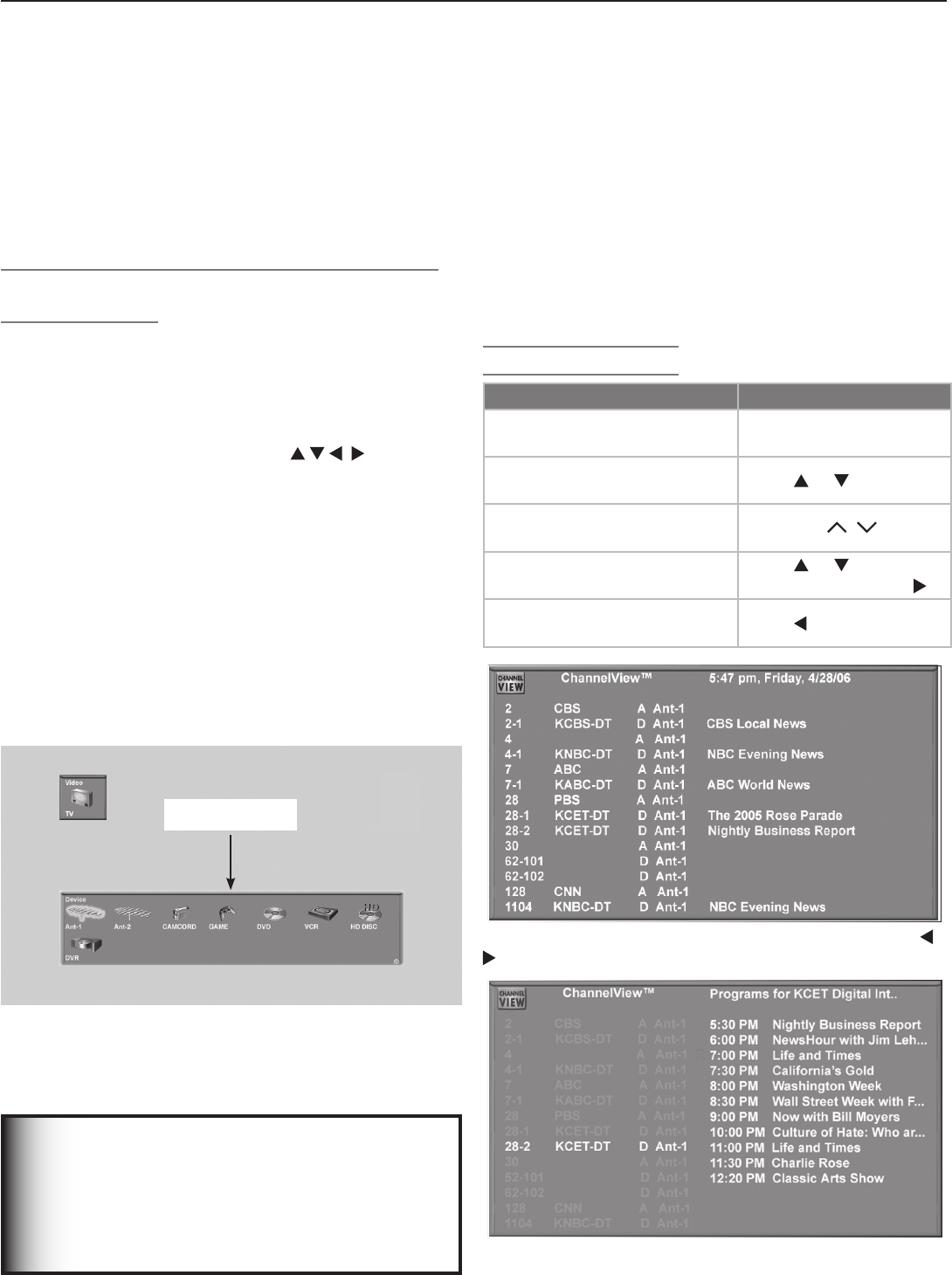
38 Chapter 3. TV Operation
Choosing a Program Source
NOTE: If your only viewing sources are connected to the
ANT 1
and
ANT 2
antenna jacks, you can switch
inputs without the Input Selection menu. Press
INPUT
to switch between
ANT 1
and
ANT 2
. To
verify which is the current source while watching
TV, press
INFO
to see the on-screen status display.
Selecting from Multiple Sources: The Input
Selection Menu
The Input Selection menu allows you to select an input to
watch on the TV. The current input appears as a gold-
colored icon.
1. Press
INPUT
on the TV’s remote control to display the
Input Selection menu (Figure 2).
2. To select a different input, press on the TV’s
remote control to move the highlight through icons in
the input section.
3. Press
ENTER
to switch to the device and close the menu.
More About the Input Selection Menu
• To assign meaningful labels to the icons, such as
“VCR” or “DVD,” see the “Input Name” section of
chapter 4, “TV Menu Settings.”
• To rearrange the icons, see the “Icon Order” section of
chapter 4, “TV Menu Settings.”
• To use with IEEE 1394 devices, see additional informa-
tion in chapter 7, “Using IEEE 1394 Devices.”
Input Section
Figure 2. Input Selection menu
ChannelView™ Channel Listings
ChannelView provides program information only when pro-
vided by the broadcaster for memorized digital channels
on ANT 1 or ANT 2. Digital channels are indicated with a
“D” and analog channels with an “A.”
Digital channels are shown with the major channel and
sub-channels (or bitstreams). Analog channel names are
shown only if they are named in the channel menu.
Note: If limited data is shown or no program data ap-
pears, it is because the broadcaster is not sending
the information. This is not a defect of your TV.
Using ChannelView
Feature Instructions
View listings while viewing
ANT 1
or
ANT 2.
Press
GUIDE.
Scan through memorized
channels one by one. Press or .
Scan quickly through memo-
rized channels. Press
PAGE
/ .
View future program informa-
tion for digital channels
.
Press or to highlight
a channel and press .
Return to viewing basic list-
ings information Press .
Figure 3. ChannelView screen, current programs. Use
to exchange displays for current and future programs.
Figure 4. ChannelView screen, future programs on the
selected channel (digital channels only)
IMPORTANT
To receive ChannelView updates: Set the
Energy Mode to Fast Power On and leave the
TV powered off for a while each day. If the TV
loses power, program listings will be lost until
the next update.
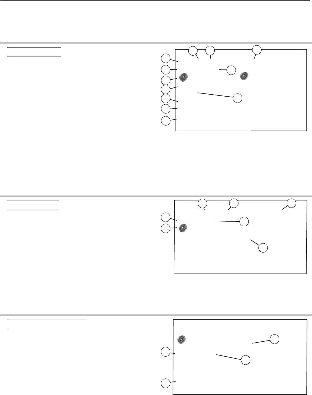
Chapter 3. TV Operation 39
Status Display
The on-screen status display appears when you turn on
the TV, change inputs, change channels, or press the
INFO
button on the remote control.
The most common displays are shown below. Seldom or
never do all the status indicators appear at the same time.
Analog Program
1. Source Antenna or Input
2. Analog Channel being received (If an antenna
source)
3. Channel Name (if named in the Channel menu)
4. Signal Type Being Received. Possible:
From
ANT-1
,
ANT-2
, or
INPUT
jacks: 480i
From
COMPONENT
jacks: 480i, 480p, 720p,
1080i
5. Screen Format in use
Possible:
Analog 480i /480p signals: Standard, Expand,
Zoom, Stretch, Stretch Plus, Narrow
720p/1080i signals: Standard, Wide Expand
6. Stereo and/or SAP being broadcast. In Split
Screen mode, the speaker icon is on either the left
or right to indicate the sound source.
7. V-Chip Ratings
8. Channel is in current FAV bank (FAV bank 2)
9. Day and Time
Ant-1 3 XXXX ANT-1 3
480i Standard
Stereo SAP
TV-PG DLSV
FAV2
Monday 11:00 AM
Sleep Timer: 30
MUTE
11
3
2
6
7
1
8
9
10
12
45
10. Sleep Timer remaining time
11. Split Screen picture source and channel
12. Audio Mute on
Digital Program
1. Digital Major and Sub-Channel Number
2. Digital Channel Name (only if broadcast)
3. Signal Type Being Received
Possible: SD 4:3, SD 16:9, HD
4. Screen Format in Use
Possible:
SD 4:3: Standard, Expand, Zoom, Stretch, Stretch
Plus, Narrow
SD 16:9 or HD: Standard, Wide Expand
5. Language(s) being broadcast
6. Program Name (if broadcast)
7. Copy- Protection Status. Possible:
Copy Once: Program can be recorded
Copy Never: Program can never be recorded.
Ant-1 42-1 XXXXXXX XXXXXXXXXXXXXX
HD Standard
English
TV-PG DLSV Copy Never
FAV2
Monday 11:00 AM
Sleep Timer: 30
6
7
1
34
5
2
Digital IEEE 1394 Device
1. Status of D-VHS VCR or IEEE 1394 device
2. Counter of D-VHS VCR
3. Special message line (shows only when a special
message is needed; may be seen with analog
signals)
4. Copy- Protection Status. Possible:
Copy Once: Program can be recorded
Copy No More: Program can no longer be recorded;
program may be moveable.
Copy Never: Program can never be recorded.
DVCR
HD Standard
English
TV-PG DLSV Copy No More
Play 01:20:15
Monday 11:00 AM
Sleep Timer: 30
Special Message Line
1
3
2
4

40 Chapter 3. TV Operation
TV Signals and Picture Formats
This is a widescreen TV, also known as a 16:9 TV. This
shape reflects the new types of picture formats available
from HDTV and many DVDs. There are still many older
style narrow-screen picture formats (for example, 4:3
aspect ratio) you will encounter. While there is no perfect
solution for displaying a squarish, narrower image on a
wide screen, Mitsubishi offers several picture formats
from which you can choose.
Note: “Picture format” refers to the aspect ratio or the relative
size/shape of the picture, such as 16:9 or 4:3.
Press
FORMAT
on the TV remote control to cycle through the
available picture formats. The last-used format for each
device is used when you return to that device.
Note: In Split Screen mode, the
FORMAT
key changes
the picture size on both sides of the screen, but
the aspect ratio (relative height and width) of both
pictures remains the same.
DVD Definitions
Anamorphic (or Enhanced for WideScreen TV)
These DVDs are recorded in a special way to properly
show widescreen pictures on 16:9 TV sets using the
Standard format mode. This is the recommended viewing
choice.
Non-Anamorphic (or 4:3, 1:33:1, Letter Box, or Full
Screen)
These DVDs are recorded for use with traditionally shaped,
squarish TVs. They may be full screen (4:3 or 1:33:1)
which crops movies to fit the narrow TV, or letter box,
which adds black top and bottom bars.
This information may be listed on the DVD case. Some
DVDs support both types of recordings.
Signal Definitions
480i Signals: Traditional analog interlaced signals from
or through
ANT-1
and
2
,
INPUT 1
–
3
,
COMPONENT
1
and
2
,
HDMI 1
and
2
.
480p Signals: Progressive-scan DVD signals on
COM-
PONENT
inputs and
HDMI 1
and
2
.
720p and 1080i Signals: High-definition signals received
through
COMPONENT
inputs and
HDMI 1
and
2
.
These signals are always 16:9 (widescreen).
1080p Signals: High-definition signals received through
HDMI 1
and
2.
SD 4:3: Standard-definition narrow-screen format signals
from digital channels and IEEE 1394 devices.
SD 16:9: Standard-definition widescreen format signals
from digital channels and IEEE 1394 devices.
HD: High-definition wide-screen format signals from digital
channels and IEEE-1394 devices. These signals are always
16:9 (widescreen).
TV Picture Format Definitions
Standard: This is the full-screen format. HDTV signals
use this format. This format is useful for displaying
Anamorphic DVDs that have 1.78:1 or 1.85:1 aspect ratios.
Anamorphic DVDs that have a 2.35:1 aspect ratio are
displayed with black bars at the top and bottom, but show
the entire picture correctly. Narrow (4:3) pictures are
stretched evenly from side to side. Available for all signals.
Expand: This enlarges the picture to fill the screen, crop-
ping off some of the image at the top and bottom. This is
useful for reducing the letter box top and bottom bars of
non-anamorphic DVD images. Available for 480i, 480p,
and digital SD 4:3 signals only.
Zoom: This enlarges the picture, cropping off some of
the image at each side and top and bottom. This is useful
for removing or reducing the black top and bottom bars
on anamorphic DVDs with a 2.35:1 aspect ratio. Available
for 480i and 480p and SD 4:3 signals only.
Stretch: This format stretches a narrow (4:3) picture
across the screen; there is less stretch in the center than
at the sides, however. This allows the entire narrow image
to be displayed across the screen with less distortion than
is seen in the Standard format. Available for 480i and
480p and SD 4:3 signals only.
Stretch Plus: Similar to stretch mode, but to minimize
distortions on the side, the picture is expanded to crop
off portions of the top and bottom. Except when display-
ing menus, press to adjust the position of the picture
vertically. Available for 480i and 480p and SD 4:3 signals
only.
Narrow: This format displays narrow (4:3) pictures in their
original shape, and adds stationary black side bars to fill
the screen. Available for 480i, 480p and SD 4:3 signals
only.
Wide Expand: Enlarges the picture, cropping some of
the image on both sides. This Expand format is useful to
remove or reduce black side bars added to narrow pic-
tures that are converted to 16:9 signals for digital broad-
cast. Available for 1080i, 720p, digital SD 16:9 and digital
HD signals.
Note: All high-definition channels send widescreen (16:9)
signals, but not all programming sent on these
channels was created for this format. As a result,
the broadcaster must convert such programming
for broadcast, and may stretch the picture or add
side bars to fill the widescreen area.
Chapter 3. TV Operation 41
TV Picture Formats
See descriptions on the preceding page.
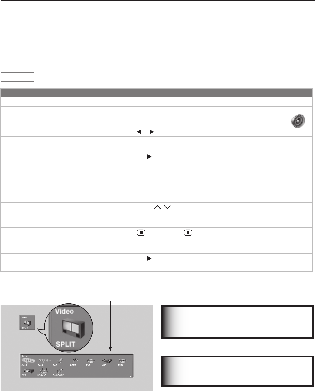
42 Chapter 3. TV Operation
Split Screen
Split Screen allows you to view pictures from two different
sources at the same time. Split Screen is available when
you have video sources connected to the TV in addition to
any connections to
ANT 1
and
ANT 2
.
Operation
IMPORTANT
Split Screen is not available if your only inputs
are ANT 1 and ANT 2.
Split Screen Operations Instructions
Turn Split Screen on or off Press
SPLIT
.
Switch the sound source between main
and sub-pictures.
The speaker icon appears briefly over the active picture (main
or sub-picture). The side that is active will be controlled by the
remote control.
Press or switch between main and sub-picture sides.
Check which picture is the sound source. Press
INFO
. The speaker icon appears in the information display to indi-
cate the sound source.
Change the source of the sub-picture.
1. Press to make the sub-picture the sound source.
2. Press
INPUT
and move the highlight to the icon for the input you wish
to view as the sub-picture (see figure 5).
3. Press
ENTER
to make the change.
Grayed-out input icons are unavailable as Split Screen sources or with
the current source.
Change channels (when the input source is
ANT 1
or
ANT 2
)
.
• Press
CH
/ .
• With the main picture as the sound source, enter the channel
number and press
ENTER
.
Freeze or unfreeze the sub-picture. Press (
PAUSE
). Press again to return to normal moving video.
Change the size of the main and sub-pic-
tures.
Repeatedly press
FORMAT
to cycle through picture sizes. See the follow-
ing page for sample displays.
Make the sub picture fill the screen. 1. Press to make the sub-picture the sound source.
2. Press
SPLIT
to close Split Screen mode.
Figure 5. Change the source of the sub-picture with the
Split Screen Input Selection menu.
Choice of Split Screen
sub-Picture Sources
“SPLIT” appears under the
Video icon to distinguish
this menu from the Input
Selection menu.
IMPORTANT
PCs and HDMI 1080p devices cannot display in
the Split Screen sub-picture.
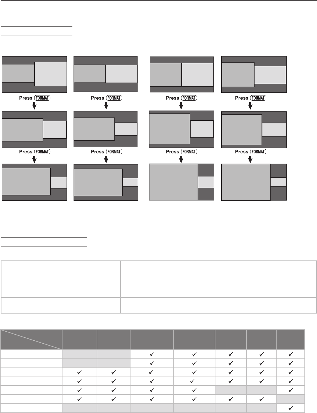
Chapter 3. TV Operation 43
TV Inputs for Split Screen
The available Split Screen picture sources are listed below.
Available as either main picture or sub-
picture
• Analog channels
• Devices on
VIDEO
/
S-VIDEO
inputs
• Devices on
COMPONENT
inputs
• Devices on either
HDMI
1
or
2
inputs. Note: The main and sub-
picture can not both have HDMI inputs.
Available as main picture only • Digital channels received from HDMI 1080p
• PC
Display choices. Press the
FORMAT
key repeatedly while in Split Screen mode to view different displays.
Note: When PC or HDMI 1080p is the signal source for the Main picture, only one size combination is
available. Pressing the Format button will not change the size of the images.
Split Screen Displays
16:9 Main
Picture
16:9 Main
Picture
16:9 Main
Picture
16:9 Main
Picture
16:9 Main
Picture
16:9 Main
Picture
4:3 Sub-
Picture
4:3 Sub-
Picture
4:3 Sub-
Picture
4:3 Main Picture
4:3 Main Picture
4:3 Main Picture
16:9 Sub-
Picture
16:9 Sub-
Picture
16:9 Sub-
Picture
4:3 Main Picture
4:3 Main Picture
4:3 Main Picture
4:3 Sub-
Picture
4:3 Sub-
Picture
4:3 Sub-
Picture
16:9 Sub-
Picture
16:9 Sub-
Picture
16:9 Sub-
Picture
16:9 Main Picture/
4:3 Sub-Picture
16:9 Main Picture/
16:9 Sub-Picture
4:3 Main Picture/
4:3 Sub-Picture
4:3 Main Picture/
16:9 Sub-Picture
Combinations of picture sources you can view with Split Screen. Check marks indicate available combinations.
Sub-
Picture
Main
Picture
ANT 1 ANT 2 INPUT
COMPONENT HDMI 1
(no 1080p)
HDMI 2
(no 1080p)
IEEE
1394
ANT 1
ANT 2
INPUT
*
COMPONENT
**
HDMI 1 & 2
IEEE 1394
PC-DVI
* Only when main picture and sub-picture are from different
INPUT
jacks
** Only when main picture and sub-picture are from different
COMPONENT
jacks
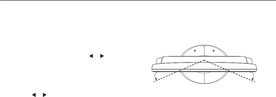
44 Chapter 3. TV Operation
Manual and Power Swivel
Both TV models allow you to swivel the TV manually up to
30 degrees from left to right. In addtion, the LT-37131
model
has the Power Swivel feature, which automatically swivels
the TV left or right when you press the or buttons on
the remote control.
To use the Power Swivel feature for LT-37131:
1. Be sure no menu or slider (such as the Volume slider)
is displayed.
2.
Press the or buttons to swivel the TV thirty degrees
left or right.
Note: Power Swivel is not available while the TV is i
n Split
Screen mode.

4
TV Menu Settings
3D Graphical Menu System ...................... 46
Main Menu ........................................ 47
Setup Menu ....................................... 48
Input Name Menu ................................... 50
Icon Order Menu ................................... 50
Channel Menu ..................................... 51
Captions Menu ..................................... 53
Parental Lock Menu ................................. 55
Setting a Pass Code ................................. 55
Lock TV by Time and Front-Panel Lock . . . . . . . . . . . . . . . . . . . . . . 55
Rating Menus ..................................... 55
Bypassing the Ratings Lock and Lock by Time . . . . . . . . . . . . . . . . . 57
V-Chip Signal Information
TV Ratings ....................................... 58
Movie Ratings ..................................... 58
Audio/Video Menu .................................. 59
Audio Settings ..................................... 60
Video Settings ..................................... 61
46 Chapter 4. TV Menu Settings
Menu Screens
A picture (icon) is highlighted on the menu
screen when selected with the directional
arrows . You may then make
changes within the menu or access sub-
menus, if available.
You can also open sub-menus from a
button. Sometimes when you select a
button, an automatic function begins.
3D Graphical Menu System
Your TV has Mitsubishi’s exclusive 3D Graphical on-screen operating system, which provides on-screen
information for menu choices and changes using the TV’s remote control.
The system includes the following special fea-
tures:
• The currently selected icon or button is highlighted
with a yellow outline; the text color is yellow.
• On-screen instructions, shown in the message line at
the bottom of the menu, provide feature selection and
adjustment information.
• Some on-screen menu options must be set before
other options are available.
Remote Control Buttons
The following buttons on the remote control help you navigate within the
system:
Key Function
1
MENU
Display or close the Main menu or move back
one menu screen at a time.
2
EXIT
Close all menus and return to TV viewing.
3
( Adjust Left/Right Keys) to select a menu item to change.
4
(Adjust Up/Down Keys)
• to change the settings.
• to scroll through pre-set text-box entries.
5
ENTER
Open a menu, start an automatic function, or
select a check box.
6 Numbers, Letters Enter custom names in some text boxes.
7
CANCEL
Clear a setting or stop an automatic function.
1
2
3
4
5
6
7
3
4
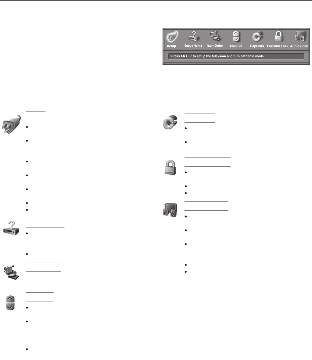
Chapter 4. TV Menu Settings 47
Setup
Select English or Spanish for menus and
on-screen displays.
Memorize the available channels for the
antenna or cable service connected to the
ANT 1
and
ANT 2
jacks.
Set the TV’s internal clock either manually
or have the TV set the clock automatically.
Set the TV Timer to turn on the TV auto-
matically at a designated time.
Set the energy mode for power consump-
tion when the TV is powered off.
Turn off Demo Mode.
View the TV’s software version.
Input Name
Assign useful names to TV inputs so that
you can easily find them in the Input Selec-
tion menu.
Select analog or digital PC DVI signal types.
Icon Order
Rearrange icons in the Input Selection menu to
put frequently used icons first.
Channel
Edit channels for the
ANT 1
and
ANT 2
inputs.
Manually add or delete channels from
memory, name analog channels, or add
your favorite channels to a FAV (Favorites)
list.
View signal strength of a currently tuned
digital channel.
Main Menu
Press
MENU
on the remote control to open the Main menu,
figure 1. See below for an overview of the options available
through the Main menu.
Figure 1. Main menu.
Captions
Display closed captions (if sent by the
broadcaster).
Select settings for analog or digital cap-
tions.
Parental Lock
Block or allow programming based on
rating signals sent by the broadcast station.
Lock the TV by time.
Lock the front-panel buttons.
Audio/Video
Reset a selected device’s A/V memory to
the original factory settings.
Customize individual audio and video set-
tings.
Display a blue screen when viewing a
device with no video signal or a poor video
signal.
Enable/disable Film Mode.
Turn the TV speakers on or off.
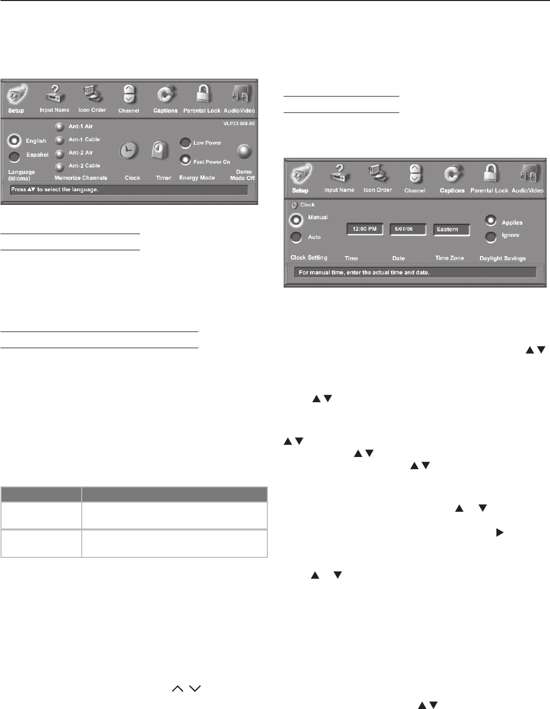
48 Chapter 4. TV Menu Settings
Note: If using a CableCARD™, the complete list of
available channels is provided through the
CableCARD and the ANT 1 option is grayed out.
Clock (Setup Menu)
Set the clock if you wish to use the TV’s Timer function
or schedule delayed recordings. You can use either the
manual or auto method to set the clock.
Figure 3. Clock submenu
Setting the Clock Manually
Time
With the hour highlighted in yellow characters, press
repeatedly to slowly increment the hour and associated
AM/PM indicator or press and hold to quickly increment
the hour. Press
ENTER
to highlight the minutes in yellow.
Press to set the minutes.
Date
With the month highlighted in yellow characters, press
to select the correct month. Press
ENTER
to highlight
the day. Press to select the correct day. Press
ENTER
to highlight the year. Press to select the current
year.
Time Zone
Select your correct time zone. Press or to select
the time zone for your area (Atlantic, Eastern, Central,
Mountain, Pacific, Alaska or Hawaii). Press to move
to the Daylight Savings option.
Daylight Savings
Press or to select either Applies or Ignore, depending
on whether or not daylight savings time is used in your area.
Note:
If Clock Setting is set to Manual, each time the time
change occurs, you must open this menu and set the
TV’s clock ahead or back.
If you have selected Auto for Clock Setting, the TV’s
clock adjusts automatically to daylight savings time.
Setting the Clock Automatically
Select the Time Zone and the Daylight Savings (DST)
options for your state. Press to select Applies or
Ignore. You may then tune to a channel on ANT 1 or
ANT 2 that uses Extended Data Service (XDS) time data,
Setup Menu
Figure 2. Setup menu
Language (Setup Menu)
Choose to display the on-screen menus in either English
or Spanish (Español).
To listen to audio in other languages (when available), see
the “Audio Settings” section in this chapter and refer to
“SAP” (analog signal) or “Language” (digital signal).
Memorize Channels (Setup Menu)
For ANT 1/MAIN and ANT 2/AUX
The memorization process performs two scans of all
possible channels on the selected
ANT
input. Analog
channels are scanned first, then the process is repeated
for digital channels. Channel memorization may take up
to 15 minutes to complete.
To start channel memorization
1. Highlight an input selection based on your connec-
tions:
Input Condition
Ant 1 Air,
Ant 2 Air
When connected to an indoor/outdoor
antenna
Ant 1 Cable,
Ant 2 Cable
When connected to direct cable (no
cable box)
2. Press
ENTER
to start automatic channel memorization.
To stop channel memorization before completion
Press
CANCEL
.
Channels memorized before you pressed
CANCEL
are
retained in memory. If you restart memorization, all previ-
ously memorized channels for the selected antenna input
are erased and the process starts over from the begin-
ning.
After channel memorization, press
CH
/ to tune
to memorized channels. Select the Channel menu for
further channel editing, such as adding and deleting
channels from memory, naming channels, and saving
favorite channels in custom memory banks.
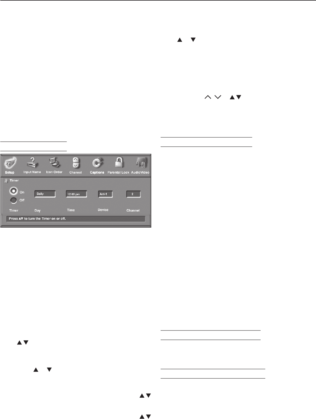
Chapter 4. TV Menu Settings 49
Timer (Setup Menu)
Figure 4. Timer submenu
The Timer feature allows you to set a day and time for the
TV to turn on automatically and the device and channel to
display when it switches on. If the TV is already on at the
requested time, the TV automatically tunes to the channel
you designated in the Timer menu.
When the Timer turns on the TV, the following message is
displayed: “Press a button for the TV to stay on.” Press
any button on the remote control within five minutes if you
wish the TV to remain on.
Note: The TV clock must be set before you can use the
Timer feature (see preceding page to set the clock).
On/Off
Press to enable or disable the Timer.
Set Day
Select the day or days that the TV will turn on automati-
cally. Press or to select Daily, Mon-Fri (Monday
through Friday), or individual days of the week.
Set Time
With the hour highlighted in yellow characters, press
repeatedly to slowly increment the hour and associated
AM/PM indicator or press and hold to quickly increment
the hour. Press
ENTER
to highlight the minutes. Press
to set the minutes.
Device
Press or to select the device to use when the Timer
turns on the TV. If the TV is already on at the selected
time, the Timer will switch the TV to this device.
Channel
When the selected device is an antenna, you can select a
channel for the TV to tune to when it comes on. Highlight
the Channel box and
• press
CH
/ or to choose from memorized
channels.
• Enter a channel number from the remote control.
You can also enter sub-channel numbers for
digital channels.
Energy Mode (Setup Menu)
The Energy Mode option lets you select the TV’s level of
power consumption while the TV is turned off. Choose
either Low Power or Fast Power On. The Low Power
setting uses less energy, but TV power-on takes longer.
The default is Fast Power On. Keep this setting at Fast
Power On if you:
• Need faster power on.
• Wish to turn off the TV while recording to an IEEE
1394 device.
• Wish to schedule future IEEE 1394 recordings for
a time when the TV will be off.
• Expect to use the TV Timer function to turn on the
TV at a preselected time.
• Need the TV Clock to remain accurate for the TV
Timer and for scheduling recordings. With the
Low Power setting, you must reset the TV Clock if
the TV is left turned off for over 48 hours.
• Wish to receive updates to the ChannelView™
channel listings.
Note: CableCARD™ requires the Fast Power On setting.
If you insert a CableCARD™, the TV will automati-
cally override a Low Power setting and change to
the Fast Power On setting.
Demo Mode Off (Setup Menu)
Some TVs are shipped from the factory with Demo Mode
active for use in retail stores. If Demo Mode is active,
highlight the Demo Mode Off button and press
ENTER
.
Software Version (Setup Menu)
For servicing purposes it may be necessary to know the
software version in your TV. This information is displayed
at the right side of the Setup menu screen.
typically a PBS channel. With Auto selected, the TV
automatically retrieves the correct time and date informa-
tion from this channel.
Be aware that if a channel displays incorrect time infor-
mation, it is because of information sent from the broad-
caster and is not a defect of the TV.
Note: You may find that some channels send the incor-
rect time and the TV clock is reset every time you
tune to those channels. To prevent unwanted
clock resets, first use the Auto method to set the
clock from a channel sending the correct time,
then change the method to Manual.
Setup Menu, continued
50 Chapter 4. TV Menu Settings
Input Name Menu
Use the Input Name menu to assign useful labels to the TV
inputs that appear in the Input Selection menu. Unused
inputs appear grayed out and unselectable.
Use the PC DVI option to specify the type of video signal
coming from your computer, either Analog or Digital. For
more about this option, see chapter 6, “Using the TV with
a Personal Computer.”
Detected Inputs that Can
Be Renamed
Type of Video Signal from
Personal Computer
Figure 5. Input Name menu
To rename an input
1. If you are currently watching the input you wish to
rename, change to another input. To do so, press
INPUT
to open the Input Selection menu, highlight a different
input, and press
ENTER
.
2. With the Input Name menu displayed, press to
move the highlight to the box for the input you wish to
rename.
3. Press to select from the following list.
Cable Box Game
Camcorder HD Disc
DVD Satellite
DVD2 VCR
DVR (digital video recorder, recordable
DVD)
Only one VCR label is available, so If you have a
second VCR connected, leave the name as the default
name.
IMPORTANT
It is possible to use the same name for more
than one input. To avoid confusion, be sure
to use different names for each input.
To Remove the Icon for an HDMI Device
When you disconnect an HDMI device, the icon remains in
the Input Selection menu until you choose to remove it.
1. In the Input Name menu (see figure 5), highlight the
box for the disconnected HDMI input.
2. Press to select Off.
3. Press
EXIT
to close all menus.
Icon Order Menu
The Icon Order menu allows you to rearrange the device
icons that appear in the Input Selection menu. Change
the sequence to put frequently used icons at the start of
the list.
To change the icon order
1. Press to highlight the icon to be moved and
then press
ENTER
.
2. Press to drag the icon to the desired posi-
tion. Press
ENTER
to set the new position.
Figure 6. Icon Order menu
Chapter 4. TV Menu Settings 51
Channel Menu
Settings for the Channel
Number Shown
FAV Memory
Banks
Signal-Strength Indicator
(digital channels only)
Figure 7. Channel menu
Antenna (Channel Menu)
Select either 1 (
ANT 1 MAIN
) or 2 (
ANT 2 AUX
) as the
antenna source for the channels you wish to edit.
Channel (Channel Menu)
Select the affected channel number (shown in the Channel
box) in any of three ways:
• Press
CH
/ to select from channels already in
memory. If you also wish to tune to the channel,
press
ENTER
.
• With the channel box highlighted, press to move
through all channel numbers, one at a time. If you
also wish to tune to the channel, press
ENTER
.
• With the channel box highlighted, enter the number
directly and press
ENTER
. Note that with this method,
you must press
ENTER
for the screen to display settings
for the selected channel.
Channel numbers can be one part, analog or digital (up to
the number 16383), or two part for digital channels. For
a two-part digital channel, press
—
CANCEL
on the remote to
enter a separator after the first, second, or third number,
depending on the broadcaster’s channel information.
For digital channels, when the broadcaster has sent a
virtual channel number, the virtual channel number is
shown in the text box and the original physical digital
channel is shown below on screen as a reference. One
original channel number can be associated with several
different virtual channels.
Memory (Channel Menu)
After the available channels have been memorized with
Memorize Channels on the Setup menu, you can add
weaker channels or delete unwanted channels using this
option. For example, if you wish to see only digital chan-
nels listed, use this menu to delete analog channels from
memory.
Press
CH
/ to review the channels in memory. Press
to select Added or Deleted for the channel shown in
the Channel box.
Name
Analog channels from
ANT 1
and
ANT 2
can be named
with up to four characters. The name you enter here will
appear on the TV screen as part of the on-screen status
display. Digital channels may already be named if the
broadcaster sends the information.
1. Press a number key repeatedly to cycle through the
characters associated with the key. You can also use
to change a highlighted character.
2. Press
ENTER
to set the letter and move to the next letter
position. Press
CANCEL
to move back one position.
Signal Strength (Channel Menu)
Displays the approximate signal strength of the cur-
rently tuned digital channel. Use this indicator to help
you adjust the antenna direction for best signal reception.
The taller the bar, the stronger the signal. This indicator
applies only to digital channels.
To view the effects of antenna adjustments on digital
channels, tune to the digital channel you wish to measure
while remaining in this menu. To tune to a channel, either:
• Highlight the channel box, press
CH
/ or to
display the desired channel number, and press
ENTER
.
• Enter the channel number on the remote control and
press
ENTER
.
Terminology
Virtual Channel Number
A channel number used by a local broadcaster to
help you identify their digital channel. Usually this
is associated with their traditional analog channel
number.
Physical Digital Channel Number
The channel number officially assigned to the actual
broadcast frequency.

52 Chapter 4. TV Menu Settings
FAV (Channel Menu)
The FAV feature lets you store groups of favorite channels
in up to nine different FAV memory banks. For example,
each household member can store favorite channels in
their own bank or you can store groups of channels by
content, e.g., news, sports, children’s programming, etc.
You can store the same channel in multiple FAV banks.
FAV Setup Using the Channel Menu
Initial Setup of a FAV Bank and
Adding FAV Channels Using the
Menu
1. With the Channel menu displayed, select a channel using one of the
methods described on the preceding page, for example, press
CH
/
for a memorized channel.
2. Highlight the desired bank (FAV1–FAV9) and press
ENTER
to check mark the
selected FAV memory bank. The channel number displayed has now been
added to the checked FAV bank.
3. With the FAV bank still highlighted, press
CH
/ to display the next
channel you wish to add to the FAV bank.
4. Press
ENTER
to add a check mark next to the highlighted FAV bank.
5. Repeat steps 2–4 for additional channels and FAV banks.
Removing FAV Channels Using the
Menu
1. With the Channel menu displayed, press
CH
/ to display the memo-
rized channel you wish to remove.
2. Highlight the desired FAV memory bank (FAV1–FAV9).
3. Press
ENTER
to remove the check mark.
Channel Menu, continued
Once you have added a channel to FAV memory, FAV
and the memory bank number appear under the tuned
channel number on the TV screen. You can access the
FAV feature through the Channel menu or you can bypass
the menu and use only the remote control.
Using FAV Channels
Viewing FAV Banks
1. Press the
FAV
key. Wait for the TV to tune to a channel in the current FAV bank.
2. Press th
e
FAV
key repeatedly to cycle through the channels available in the
current FAV bank.
Changing FAV Banks
1. Press the
FAV
key. Wait for the TV to tune to a channel in the current FAV bank.
2. When tuning is complete and while the TV status display is still visible on
screen, press the number key for the desired bank.
Note: Wait for the channel change to finish before pressing the number key.
Otherwise, the TV may ignore the FAV number.
If No FAV Banks Are Set Up The
FAV
key switches to the previously tuned channel; works like the
QV
key.
FAV Setup Using Only the Remote Control
Adding FAV Channels 1. While watching TV, tune to the channel you want to add to the current FAV
memory bank. See the instructions above if you need to first change to a
different FAV bank.
2. Press and hold the
FAV
button for about 2 seconds. When FAV and the
memory bank number appear under the channel number, the channel has
been successfully added.
Removing FAV Channels
This procedure removes the channel
only from the selected bank and
leaves the other banks unchanged.
1. While watching TV, press the
FAV
button
2. While the TV status display is still visible on screen, press the number key
for the memory bank.
2. Press the
FAV
button repeatedly until you see the desired channel.
3.
While the channel number and FAV indicator (with correct bank number)
are still displayed on the screen, press CANCEL. You must press CANCEL
before the On-Screen Display (OSD) disappears. When the FAV indicator dis-
appears while the OSD is visible, the channel has been successfully removed.
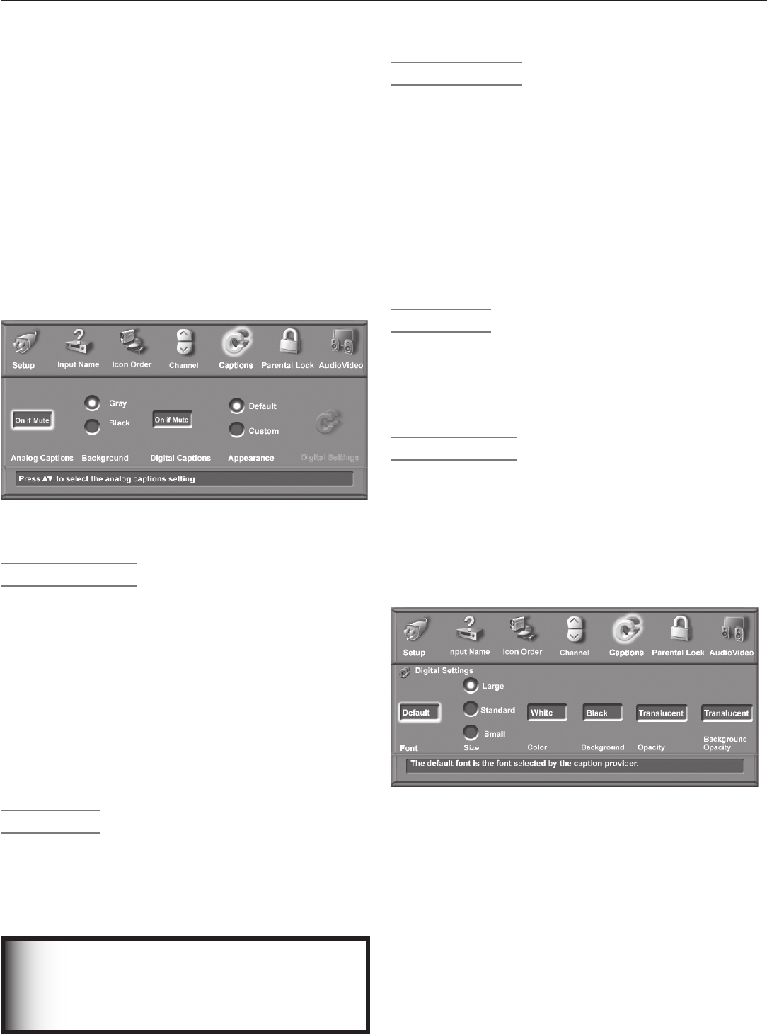
Chapter 4. TV Menu Settings 53
Captions Menu
For analog channels, broadcasters can send either stan-
dard closed captions or text service. Standard closed
captions follow the dialogue of the characters on screen
and display in a small section of the screen. Text-service
closed captions often contain information such as
weather or news and cover a large portion of the screen.
For digital channels, broadcasters can send up to six dif-
ferent captioning selections or can send analog captions
that are the same as those sent by the analog station.
Each TV station may broadcast only one or two types of
captions or none at all. The TV cannot decode closed
captions received on component or HDMI inputs.
Figure 8. Captions menu
IMPORTANT
When analog text closed captioning is
selected, a large black or gray box appears
on your TV screen if no signal is broadcast.
Analog Captions
The TV can display one of the following captions for
analog sources:
• CC1, CC2, CC3, or CC4: standard closed-caption
signals
• Text1, Text2, Text3, or Text4: Text-service signals
• On if mute: Closed captions appear when audio is
muted. When selected, press
MUTE
on the TV remote
control to turn on/off the standard closed-caption
signal CC1.
• Off: No closed captions.
Background
To make the analog closed captions easier to read, you
can choose to display the background color as either
black or gray behind the text.
Digital Captions
The following display options are available for digital
sources:
• Captions 1–6: Sent by broadcaster.
• On if Mute: Closed captions are displayed when
audio is muted. When selected, press
MUTE
on the TV
remote control to turn captioning on/off (Caption 1).
• Off: No closed captions.
Note: For digital programs, if the broadcaster is
sending only analog captions converted to digital
format, then the analog caption settings apply.
Appearance
The closed-captions provider selects the default options
when sending digital closed captions. Select Custom to
override defaults and customize the appearance of closed
captions. These settings do not apply to analog closed
captioning converted to digital.
Digital Settings
The Digital Settings menu allows you to customize the
appearance of the closed captions sent by the broad-
caster. Digital settings do not apply to analog closed
captions converted to digital.
To open the Digital Settings menu, select Custom for the
Appearance option. Move the highlight to the Digital
Settings icon and press
ENTER
.
Figure 9. Closed Captions, Digital Settings sub-menu
Font
The available font options are as follows:
• Default: Selected by the closed-captions pro-
vider
• Font 1: Monospaced font with serifs
• Font 2: Proportionally spaced font with serifs
• Font 3: Monospaced font without serifs
• Font 4: Proportionally spaced without serifs

54 Chapter 4. TV Menu Settings
Captions Menu, continued
• Font 5: Casual font
• Font 6: Cursive font
• Font 7: Small capitals
Size
Select the desired font size. Large is the recommended
font size.
Color
The available font colors are listed below. Text and back-
ground cannot be set to the same color.
White Yellow
Black Green
Magenta Cyan
Red Blue
Background
You can change the background color to make the digital
closed captions easier to read. The available background
colors are listed below. Text and background cannot be
set to the same color.
White Yellow
Black Green
Magenta Cyan
Red Blue
IMPORTANT
Mitsubishi recommends you use contrasting
colors for captions and background.
Black translucent background combined
with a white font makes an easy-to-read
combination.
Use care when selecting custom colors. Your
choice may affect the readability of captions.
IMPORTANT
The content of captions is determined by the
broadcaster. If your captions show strange
characters, misspellings, or odd grammar, it is
not a malfunction of the TV.
Opacity (Font)
You can customize the visibility of your fonts using the fol-
lowing settings:
• Translucent: TV program is dimmed behind the text
• Transparent: Invisible text reveals the TV program
behind.
• Opaque: Solid text blocks view of the TV program
• Flashing: Text flashes at intervals
Background Opacity
You can customize the background for digital captions
using the following settings:
• Translucent: TV program is dimmed behind the
background
• Transparent: No visible background
• Opaque: Solid background covers TV program
• Flashing: Background flashes at intervals
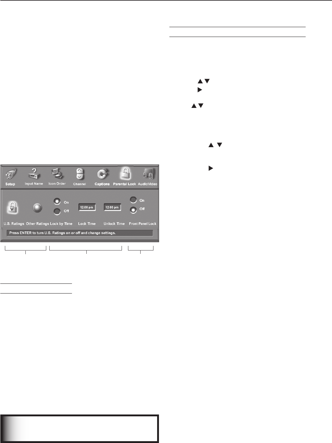
Chapter 4. TV Menu Settings 55
Parental Lock Menu
The Parental Lock menu gives you control over three
different types of parental controls. You must use a
pass code to open this menu to enable/disable the lock
options. The three parental controls available are:
• Ratings (U.S. Ratings/Other Ratings)
V-Chip technology lets you restrict access to
programming based on program-rating signals sent
by the broadcaster. For U.S. ratings, you can also set
the time of day for these restrictions to be in effect.
• Lock by Time
Lets you restrict TV use by time of day.
• Front Panel Lock
Lets you disable the controls on the front of the TV.
Use this option if there are small children near the TV
who may be tempted to press the buttons.
Access to
Ratings Menus
Lock TV by
Time
TV Front Panel
Lock On/Off
Figure 10. Parental Lock menu
Setting a Pass Code
You are prompted to enter a pass code whenever you
select Parental Lock on the Main menu. To set a pass
code for the first time:
1. Press
MENU
, highlight Parental Lock, then press
ENTER
.
A screen prompting you for a pass code will display.
2. Input a four-digit pass code using the number keys on
the remote control.
• Press
CANCEL
to delete a number and move
back one space.
• Press
MENU
or
EXIT
to close the menu without
setting a pass code.
3. Press
ENTER
to set the pass code just input.
To reset the pass code, see the procedure in Appendix A.
IMPORTANT
If you forget your four-digit pass code, see
Appendix A.
Lock TV by Time and Front-Panel Lock
Lock by Time (Parental Lock Menu)
Lock by Time allows you to block all use of the TV during
specified hours. During the lock time, you must use your
pass code to view the TV. To lock the TV by time:
1. Press to select On or Off for Lock by Time.
2. Press to move to the Lock Time box.
a. With the hour number highlighted in yellow, press
repeatedly to change the hour and associ-
ated AM/PM indicator. You can also just press
and hold to change the hour.
b. Press
ENTER
to move the highlight to the minutes.
c. With the minutes number highlighted in yellow,
press repeatedly to change the minutes.
Just press and hold to move quickly through the
numbers.
d. Press to move to the Unlock Time and set the
time as described above.
NOTE: To make Lock by Time active 24 hours a day, set
Lock and Unlock to the same time.
Front Panel Lock (Parental Lock Menu)
Front Panel Lock lets you disable controls on the front
panel to prevent inadvertent changes to TV settings.
Select On to disable the buttons and select Off to restore
their operation.
To release the front button lock without using the remote
control:
• When Energy Mode is set to Fast Power On, press
and hold the
MENU
button on the front panel for over
eight seconds. If the TV is on, a message will display
confirming release of the Front Panel Lock.
• When Energy Mode is set to Low Power, press
POWER
on the front panel to turn on the TV. Press and hold the
MENU
button on the front panel for over eight seconds.
Rating Menus
The rating menus allow you to:
• Turn rating restrictions on or off
• Change the permitted rating level
• Set the time of day to enforce rating restrictions (U.S.
ratings only)
The TV comes from the factory with pre-set U.S. V-Chip
ratings and with the rating locks turned off. The pre-set
ratings are TV rating TV-PG and movie rating PG. If you
turn on V-Chip blocking, these presets allow only programs
rated TV-PG/PG or lower until you change the rating level.
After changing the channel or device, there may be a
delay of up to five seconds before the rating restrictions
take effect.
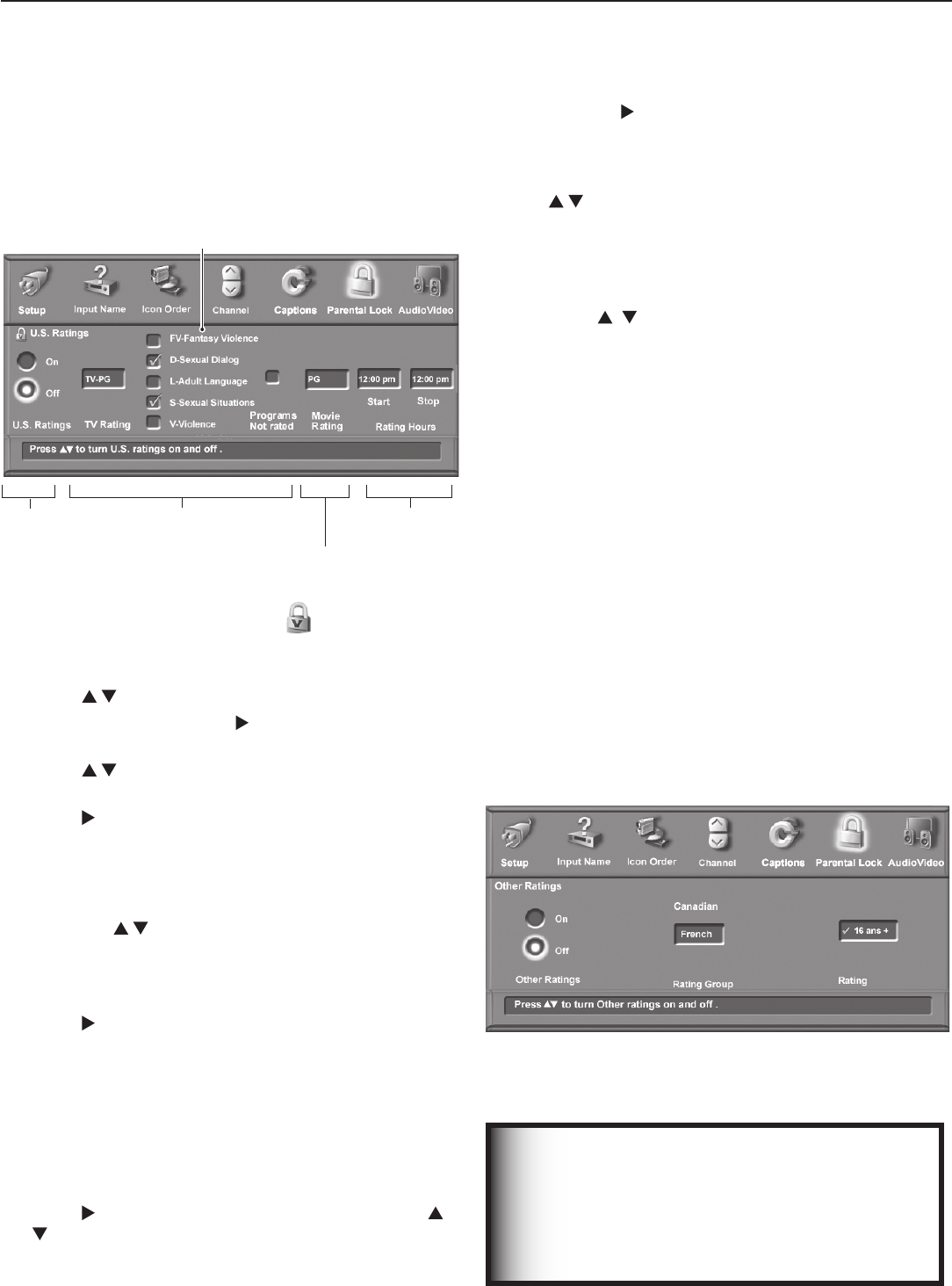
56 Chapter 4. TV Menu Settings
U.S. Ratings Menu
Use this menu to turn U.S. rating restrictions on or off and
to change the permitted rating levels.
U.S. Restric-
tions On/Off
TV Rating and
Supplemental
Restrictions
Restriction
Hours
Movie Rating
TV Content
Categories
Figure 11. U.S. Ratings menu
1. Highlight the U.S. Ratings icon on the Parental
Lock menu (figure 10) and press
ENTER
to open the U.S.
Ratings menu (figure 11).
2. Press to select On or Off.
3. If you selected On, press to move to the TV Rating
box.
4. Press to select the TV rating level you want to
allow.
5. Press to move to the TV content categories. This
section allows you to specify content blocking in addi-
tion to that blocked by the TV rating. See the section
on V-Chip ratings for an explanation of TV content
categories.
• Press to move the highlight among the
categories.
• Press
ENTER
to add a check mark to each TV
content category you want to block.
6. Press to move to the Programs Not Rated box.
Press
ENTER
to add or remove a check mark to allow or
block programs that are not rated.
Note: Use care when choosing to block unrated pro-
gramming. News programs and emergency bul-
letins carry the “None” or “NR” (Not Rated) V-Chip
signal, and they are blocked with this option ac-
tive.
7. Press to move to the Movie Rating box. Press
to select the movie rating level you want to allow.
Detailed information on rating guidelines follows this
discussion of the Parental Lock menu.
8. To set the time of day for these restrictions to be in
effect, press to move to the Start box. To make the
rating restrictions active twenty-four hours a day, set
Start and Stop to the same time. To set the time:
a. With the hour number highlighted in yellow, press
repeatedly to change the hour. You can also
just press and hold to change the hour.
b. Press ENTER to move the highlight to the
minutes.
c. With the minutes number highlighted in yellow,
press repeatedly to change the minutes.
Just press and hold to move quickly through the
numbers.
d. Repeat these steps for the Stop time.
9. Press
MENU
to return to the Parental Lock menu or
press
EXIT
to close all menus.
Other Ratings Menu
This TV can recognize new rating systems that may come
into effect in the future. The Other Ratings menu allows
you to block digital programming based on such alternate
rating systems. The alternate rating systems will apply to
digital programming only.
Note: The Other Ratings button remains inaccessible
until the TV receives signals for an alternate rating
system.
The first time you tune to a channel broadcasting an alter-
nate rating system, the TV defaults to the most restrictive
setting. Use this menu to change the allowed rating if you
are unable to watch a program broadcast with an alternate
system.
Figure 12. The Other Ratings menu is available only if the
TV receives broadcast signals carrying an alternate rating
system.
Parental Lock Menu, continued
IMPORTANT
New rating systems recognizable by the TV
may be new U.S.-based systems not included
in the original V-Chip rating system. The use
of “Canadian” in the sample screen is just
one possibility.

Chapter 4. TV Menu Settings 57
Parental Lock Menu, continued
1. Highlight the button labelled Other Ratings on the
Parental Lock menu (figure 10) and press
ENTER
to open
the Other Ratings menu (figure 12).
2. Press to select On or Off.
3. If you selected On, press to move to the Rating
Group box.
Note that you can change settings only for the rating
system available on the currently tuned channel. In
the figure above, for example, the Canadian rating
system is in effect. To change settings at a later time
for the Canadian rating system, you must again tune
to a channel broadcasting the Canadian system.
4. Press to select from the subgroups available for
the rating system—English or French in this example.
5. Press to move to the Rating box.
6. Press to select the program rating level you want
to block.
7. Press
ENTER
to add a check mark to indicate blocking is
in effect for the rating. When a rating shows a check
mark, press
ENTER
to remove the check mark and allow
programs with this rating.
8. Repeat steps 3 through 7 for each additional rating
system you would like to set up.
9. Press
MENU
to return to the Parental Lock menu or
press
EXIT
to close all menus.
Bypassing the Ratings Lock and Lock by
Time
If you try to watch blocked programming, a notice appears
prompting you for a pass code. To use the TV:
• Input your four-digit pass code and press ENTER.
• Change to a channel airing an allowed program or
change to another device.
If you try to use the TV when it is locked by time, a similar
screen appears, prompting you for your pass code.
To reactivate the rating lock or TV Lock by Time after
using the pass code, power the TV off and then on.

58 Chapter 4. TV Menu Settings
TV Ratings
TV
ratings apply to TV programs and made-for-TV movies.
You can apply supplemental blocking to TV ratings based on
the TV content categories described below. TV ratings are:
TV-Y Youth. For children under the age of 7.
TV-Y7 Youth 7 and older.
TV-G General Audience. For the entire family to view.
TV-PG Parental Guidance. Parental Guidance is
recommended; may not be suitable for some
children.
TV-14 Adolescent 14 and older. Not recommended for
children under the age of 14.
TV-MA Mature Audience. For adults only.
TV Content Categories
Used in association with the TV ratings above, TV content
categories allow you to apply supplemental blocking.
Apply supplemental blocking using the U.S. Ratings menu.
FV Fantasy Violence. Applies to TV-Y7 only.
D Sexual Dialog. Applies in different degrees to TV-PG
and TV-14.
L Adult Language. Applies in differing degrees to
TV-PG, TV-14, and TV-MA.
S Sexual Situations. Applies in differing degrees to
TV-PG, TV-14, and TV-MA
V Violence (graphic or realistic). Applies in differing
degrees to TV-PG, TV-14, and TV-MA.
TV Rating FV D L S V
TV-Y Not Applicable
TV-Y7 X
TV-PG Not
Appli-
cable
X X X X
TV-14 X X X X
TV-MA X X X
TV content categories. Boxes marked with an “X” indicate
supplemental blocking you can apply to each rating level.
The TV rating you select is for the least-restrictive program
level allowed. For example, if you select TV-PG, pro-
grams rated TV-Y, TV-Y7, and TV-PG can be viewed, but
programs rated TV-14 and TV-MA are blocked.
When you select a TV content category to block, all TV
programs with the same content category listing are
blocked. For example, if you select to block V (Violence)
at the TV-14 level, any programs with the V category
listing rated TV-PG are also blocked.
V-Chip Signal Information
When provided by the broadcaster or program source,
V-Chip ratings let you control the types of programming
that can be viewed on the TV. When V-Chip ratings are
supplied, they are displayed when you change the channel
or press
INFO
on the remote control.
V-CHIP EXCEPTIONS
• V-Chip blocking is ineffective for programs viewed
on devices connected to component or HDMI
inputs. Many of these devices, however, have their
own parental-control systems.
• Videotapes, laser discs, and DVDs may not
contain V-Chip rating signals. V-Chip cannot
block playback of recordings without V-Chip rating
signals.
• Broadcasters are not currently required to include
V-Chip rating signals. V-Chip cannot block pro-
gramming broadcast without the V-Chip rating
signal.
Movie Ratings
Movie ratings are the MPAA ratings used for theater-
released and direct-to-video movies. Movie ratings are:
G General Audience. Designed for the entire family
to view.
PG Parental Guidance. Parental Guidance is
recommended, may not be suitable for some
children.
PG-13 Parental Guidance, 13 and Older. Not
recommended for children under the age of 13.
R Restricted. Restricted in theaters to 17 years old
and older unless accompanied by an adult.
NC-17 No Children 17 or Under. Restricted in theaters
to 18 years old and older.
X Adult. Designed for and restricted in theaters to
adult audiences only.
The movie rating you select is for the least-restrictive
program level that can be viewed. For example, if you
select the PG-13 rating, movies rated G, PG and PG-13
can be watched, but movies rated R, NC-17, and X are
blocked.
Programs Not Rated: This refers to programs that carry
no rating, such as news, sports, weather, emergency bul-
letins, or movies prior to or without MPAA ratings. This
does not include programs without V-Chip signals.
IMPORTANT
If you enable blocking with the Programs
Not Rated option, you may block news or
emergency bulletins carrying the “None” or
“NR” Not Rated V-Chip rating. Use care when
blocking programming that is not rated.
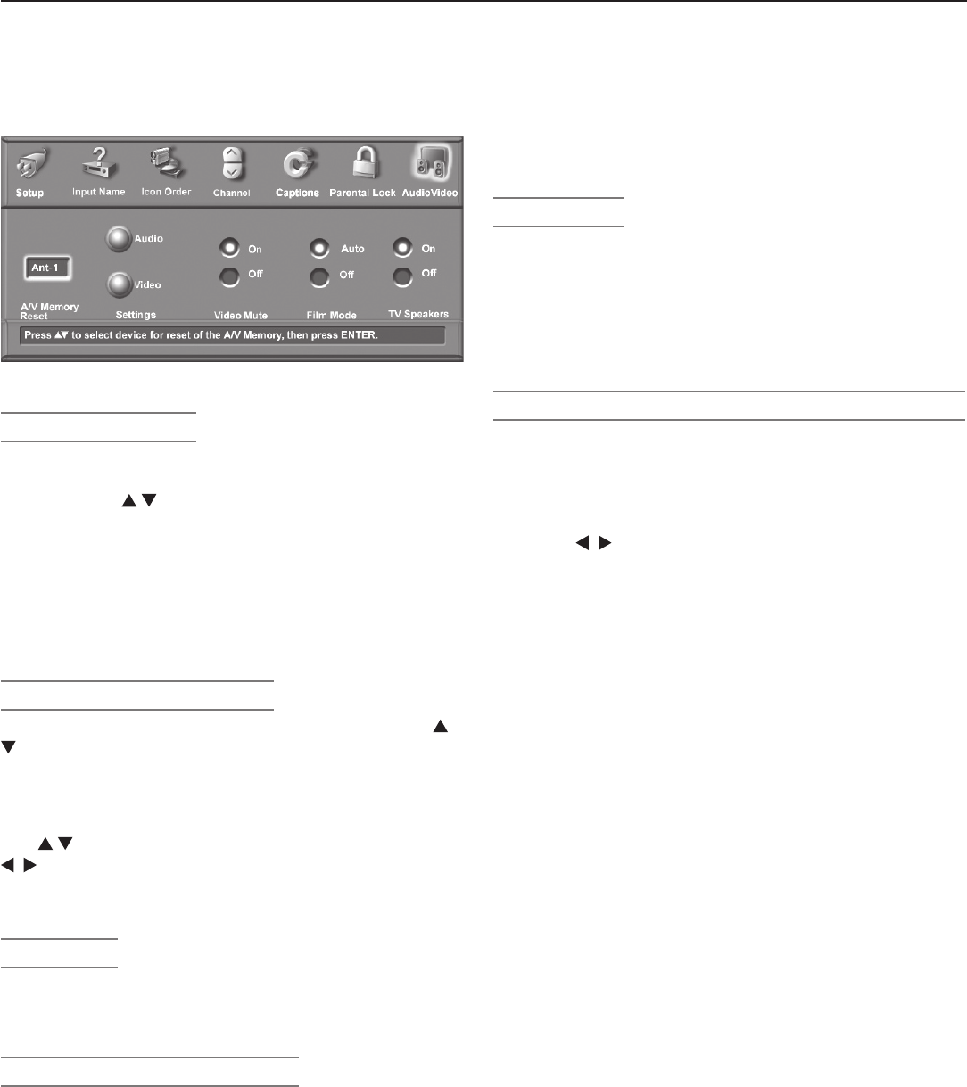
Chapter 4. TV Menu Settings 59
Audio/Video Menu
Figure 13. Audio/Video Menu
A/V Memory Reset
A/V Memory Reset allows you to reset a specific input’s
A/V settings to the original factory settings. Highlight the
box and press to select the input name. Next press
ENTER
.
The audio settings of Balance, Listen to, and Language
are general TV settings unaffected by A/V Memory Reset.
To reset all A/V settings at once, including the three
general settings, perform an A/V Reset by pressing the
front-panel buttons
GUIDE
and
FORMAT
simultaneously.
Settings (Audio and Video)
Each input or device has its own A/V memory. Press
to select the input or device in the A/V Memory Reset
box, then select Audio or Video to adjust individual
settings. Press
ENTER
to close the menu and display the
individual settings.
Use to cycle through the individual settings. Use
to change the setting values. Press
EXIT
to return to
normal TV viewing. For descriptions of the individual A/V
settings, see the following pages.
Video Mute
The default is On, which displays a blue background when
no signal is being received on the
INPUT
,
COMPO-
NENT,
or
HDMI
jacks.
Film Mode (480i signals only)
Auto is the default setting. With Auto selected, the TV
automatically detects and applies film-decoding correc-
tion for images that originated on 24-frame-per-second
film cameras and were converted to 30-frame-per-second
video for broadcast (3:2 pulldown conversion). Try the
Off setting if the TV adds noticeable jagged edges to the
images.
When the original video was filmed on 30-frame-per-
second cameras, the Auto setting automatically applies
video decoding, the same as used with the Off setting.
Film Mode is not effective for high-definition signals.
TV Speakers
This selection turns the TV’s internal speakers on or off.
Select Off when sending the sound through a separate
stereo system or surround sound A/V receiver.
Note: To prevent damage from a sudden increase in vol-
ume, turn the TV volume down low before chang-
ing this option to On.
Audio/Video Settings and the Remote Control
To adjust individual audio or video settings directly with
the remote control:
1. Press
AUDIO
or
VIDEO
repeatedly to cycle through the
available settings.
2. Press to adjust the setting. The setting display
will disappear after five seconds of inactivity.

60 Chapter 4. TV Menu Settings
Audio/Video Menu, continued
Audio Settings
Analog and Digital Audio Settings
Enter the audio adjustment mode using either the Audio/
Video menu or the
AUDIO
key. Press
AUDIO
repeatedly until
you highlight the desired audio control, then use to
change the setting, which has a corresponding numeric
value shown on screen. Values can be adjusted from 0 to
63, with 31 as the midpoint.
Note: The effects of the audio settings of Bass, Treble,
Balance, and Surround affect only the sound
heard through the TV speakers.
◊ Bass
Enhances or reduces low-pitched sound.
◊ Treble
Enhances or reduces high-pitched sound.
◊ Balance
Adjusts the level of sound between the left and right
TV speakers.
◊ Surround
Creates simulated stereo and surround effects
through the TV speakers. Your choices are:
• Off: No surround effects (default).
• Simulated Stereo: The TV creates a simulated
stereo effect when watching a non-stereo
program.
• Surround Sound: The TV creates a simulated
surround effect when watching a stereo program.
◊ Level Sound
When on, automatically equalizes the volume level
when there are significant sound-level differences
between program segments, such as between regular
programming and commercials.
• To receive the best fidelity with music programs,
change this setting to Off.
• When connecting to an A/V receiver, set Level
Sound to Off and turn off the TV speakers to
send full dynamics to the A/V receiver.
Analog-Only Audio Settings
You can set analog-only audio settings while viewing
either analog or digital sources, but the settings affect
only broadcast analog content.
◊ Listen To
Determines how your TV receives a broadcast audio
signal and plays the sound you hear.
Your choices are:
• Stereo: Default setting. The TV plays stereo
broadcasts in stereo and mono broadcasts in
mono. The word Stereo is displayed when you
tune to a channel broadcasting in stereo.
• SAP (Second Audio Program): Additional mon-
aural sound track that you cannot hear during
normal TV viewing. The SAP signal might be
related to the program you are watching, (such as
a sound track in a foreign language), or it might
be unrelated (such as a weather report). If an SAP
signal is broadcast, the letters SAP are displayed
when you tune to the channel.
• Mono: Reduces background noise. Use when
receiving a weak stereo audio signal. All audio is
played mono with this setting.
Listen To is not available for digital channels, 1394 devices
or devices connected to the
INPUT,
COMPONENT
and
HDMI
jacks.
Digital-Only Audio Settings
You can set digital-only audio settings while viewing either
analog or digital sources, but the settings affect only
broadcast digital content.
◊ Language
Determines what possible language you can hear.
Your choices are:
English Portuguese
French Spanish
German Other
Italian
IEEE 1394 Amplifier Settings
Available settings for some MPEG2 amplifiers:
◊ Balance
Adjusts the level of sound between the left and right
speakers. The slider range is 0–254, with 127 as the
midpoint.
◊ Loudness
When on, makes the audio level more uniform.
◊ Preset
Select the mode that matches the audio source.
Your choices are:
Off Classical Music
Jazz Movie
Rock Speech
◊ Equalizer
Equalizes the sound.
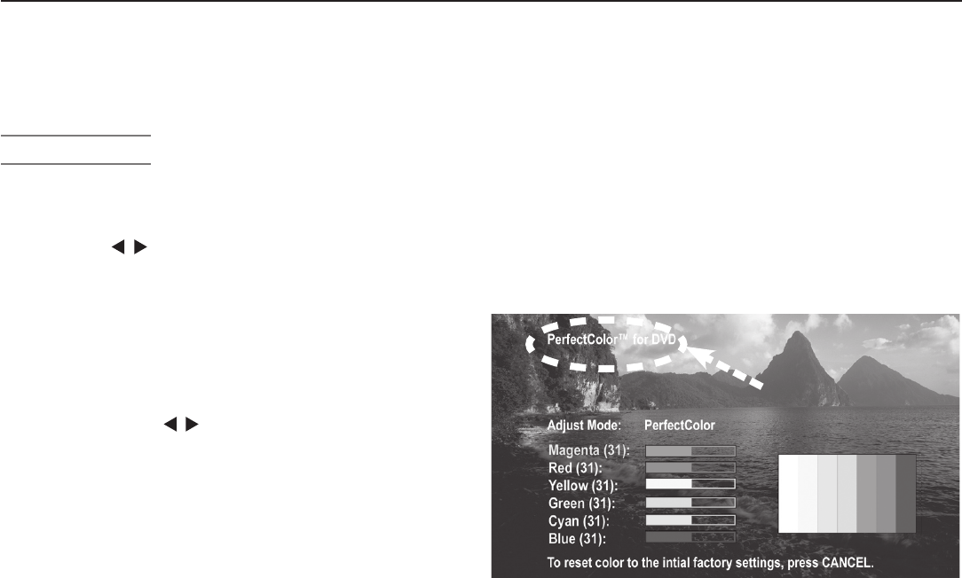
Chapter 4. TV Menu Settings 61
Audio/Video Menu, continued
Video Settings
Enter the video adjustment mode using either the Audio/
Video menu or the
VIDEO
key. Press the
VIDEO
key repeatedly
to cycle through the video options to the one you want to
change. Use to change settings.
Note: A slider displays on screen for some settings.
When the slider is displayed, it represents numeric
values, with 63 as the maximum, 31 as the mid-point,
and 0 as the minimum.
◊ (Power) Swivel: For LT-37131 model only. Swivels
the TV up to thirty degrees left or right. When a
menu or slider is displayed, Power Swivel can not be
accessed using
.
Note: Power Swivel is not available while the TV is i
n
Split Screen mode.
◊ Picture Mode: Set the Picture Mode first before
adjusting other settings, as each Picture Mode stores
its own values for Contrast, Brightness, and Color
Temperature. Picture Modes allow you to optimize the
image for different lighting conditions. The Picture
Modes are:
• Bright: Suited for most daytime viewing.
• Natural: Suited for most nighttime viewing.
• Brilliant: The default setting. For use under
strong light.
◊ Contrast (Bright/Natural/Brilliant): Provides a slider
to adjust the white-to-black level. Low contrast
shows a variety of shades in darker images, while high
contrast shows darker images more uniformly black
and makes colors appear more vibrant. In most home
lighting situations, a medium contrast looks best.
High contrast is good for brightly lit environments.
◊ Brightness (Bright/Natural/Brilliant): Provides a slider
to adjust the overall brightness of the picture.
◊ Color: Provides a slider to adjust color intensity.
◊ Tint: Provides a slider to adjust the red-to-green ratio.
◊ Sharpness: Provides a slider to adjust the detail and
clarity.
◊ Color Temperature (Bright/Natural/Brilliant): Allows
you to adjust how white is displayed.
• Low: White images have a warm cast. This
adjustment is an average and can vary due to
ambient room lighting, video scene brightness,
and the TV’s age. Natural/Color Temp at the
low setting displays video at the 6500K industry
standard for NTSC pictures.
• High: White images have a cool cast. This
setting may provide the most realistic picture
under bright lighting.
◊ PerfectColor™: Lets you adjust the intensity of
any or all of six colors (Magenta, Red, Yellow, Green,
Cyan and Blue) to create color balance for the current
image source. PerfectColor settings are memorized
for each TV input or device. Select the PerfectColor
option and press
ENTER
to open the adjustment screen.
Individual sliders for each color are displayed.
Highlighted text shows which slider you are adjusting.
Press
CANCEL
while in the PerfectColor screen to reset
all colors to the default settings.
Name of affected
input
Figure 14. Set PerfectColor adjustments independently
for each TV input.
◊ Video Noise: Reduces minor noise (graininess) in
the picture. Use the Low setting with good-quality
signals. Use Medium or High with poor-quality
signals. Turn off to leave the picture unaltered.
◊ Back Light:
Lets you adjust the TV’s back light
peak
brightness settings for optimal viewing in different
room lighting conditions. A higher setting looks more
vibrant in brightly lit rooms; a lower setting may look
more natural when viewing in a darkened room.
Personal Computer Video Settings
Video settings available for images from a personal com-
puter are:
◊ Contrast
◊ Brightness
◊ PerfectColor™. The adjustment screen displays
without the vertical color bars when used for a com-
puter image,
◊ Auto Position: Press
ENTER
to automatically center the
position of PC video.
◊
HorizPosition (Horizontal Position): Manually adjust
the horizontal position of PC video. This selection
overrides the Auto Position selection.
◊ VertPosition (Vertical Position): Manually adjust the
vertical position of PC video. This selection overrides
the Auto Position selection.
◊ Fine Detail: Manually adjust the picture quality of PC
video, analog signals only. This selection overrides
the Auto Position selection.

62 Chapter 4. TV Menu Settings

5
Operating Other Devices with the Remote
Control
Functions Available for Other A/V Devices .................. 64
Programming the Remote Control ....................... 65
Programming Codes ................................. 66
64 Chapter 5. Operating Other Devices with the Remote Control
Functions Available for Other A/V
Devices
The TV’s remote control can be programmed to operate
other types and brands of A/V products. To use the
remote when programmed, set the slide switch to the
position labelled for the product type. The functions per-
formed in each switch position can vary depending on the
product. Not all functions work for all models. The most
common functions available are listed on this page.
IMPORTANT
Some manufacturers may change their
products or they may use more than one
remote control system. The TV’s remote
control may be unable to operate your A/V
equipment in these cases.
Set the remote control’s slide
switch to the type of device you
wish to program for or control.
VCRs and DVRs
•
CH
/
•
POWER
•
SLEEP
• (
FAST FORWARD
)
• (
PAUSE
)
• (
PLAY
)
• (
RECORD
)
• (
REVERSE
)
• (
STOP
)
•
GUIDE
(on DVRs)
•
MENU
(on DVRs)
•
0–9
Number Buttons
Mitsubishi VCRs are compatible with some additional
buttons.
Cable Boxes and Satellite Receivers
•
AUDIO
(page up)
•
CANCEL
(on some
models)
•
CH
/
•
ENTER
(on some
models)
•
GUIDE
(on some models)
•
POWER
• (on some
models)
•
VIDEO
(page down)
•
QV
(
ENTER
; for channels
on some models)
•
0–9
Number Buttons (on
some models)
•
F1–F4
(A, B, C, D keys on
some models)
The record/playback keys
(on some models):
• (
FAST FORWARD
)
• (
PAUSE
)
• (
PLAY
)
• (
RECORD
)
• (
REVERSE
)
• (
STOP
)
A/V Receivers
•
MUTE
•
POWER
•
SLEEP
•
VOLUME
•
0–9
Number Buttons
• Direct Input Selection
buttons: numbers,
FAV
and
QV
(on some
Mitsubishi models)
CD Players
(not all functions for all models)
•
SLEEP
• (
FAST FORWARD
)
• (
PAUSE
)
• (
PLAY
)
• (
REVERSE
)
• (
STOP
)
•
0–9
Number Buttons
DVD and Laser Disc Players
(not all functions for all models)
•
CANCEL
(on some
models)
•
CH
/ (on some
models)
•
ENTER
•
MENU
•
POWER
•
SLEEP
• (on some
models)
• (
FAST FORWARD
)
• (
PAUSE
)
• (
PLAY
)
• (
RECORD
)
• (
REVERSE
)
• (
STOP
)
•
0-9
Number Buttons (on
some models)
Chapter 5. Operating Other Devices with the Remote Control 65
IMPORTANT
You may need to reprogram the remote
control after changing the batteries.
Programming the Remote Control
Method 1: Code Entry
1. Move the slide switch at the top of the remote to the
position for the product you want to control. Refer to
the table below. Only one of each device type can be
controlled in each slide-switch position.
Switch Position Affected Device
CABLE/SAT
Cable Box
DTV Receiver
Satellite Receiver
VCR
VCR
DVR
Laser Disc Player
DVD Player/Recorder
DVD
DVD Player/Recorder
DVR
Laser Disc Player
VCR
AUDIO
A/V Receiver
Audio Amplifier
CD Player
2. Press and hold
POWER
on the remote control for several
seconds until the button blinks twice and goes off.
3. Release the
POWER
button.
4. Enter the first five-digit code listed for your equipment.
• The
POWER
button blinks twice when you start to
enter the code and then once for each additional
keypress.
• The
POWER
button blinks twice when you finish
entering a valid code.
• Move the slide switch to another position if you
need to start over or wish to exit programming
mode.
5. Point the remote control at the equipment and press
POWER
. If the product has no power on/off function,
press a different key, such as (
PLAY
), (
STOP
),
VOL
, or
MUTE.
• If the equipment responds, the remote control is
properly programmed to operate the equipment.
• If the equipment does not respond, repeat steps
2–4 with the next five-digit code listed for your
equipment.
6. Once you have found the correct code, write it in the
space below for future reference.
Switch Position
Device Type Code
CABLE/SAT
VCR
DVD
AUDIO
Method 2: Code Search
In this method of programming, you step through the
remote control’s internal code library to find the correct
code for your A/V product.
1. Move the slide switch at the top of the remote control
to the correct position for the product. See the table
under “Method 1.”
2. Press and hold
POWER
on the remote control for several
seconds until the button blinks twice and goes off.
3. Press keys
9 9 1
4. Press the number
1
,
2
, or
3
depending on the slide-
switch position and the table below.
Switch Position Number
CABLE/SAT
1
DVD, VCR
2
AUDIO
3
5. Press
CH
and
POWER
repeatedly until the product
responds by powering on or off. You can press
CH
to move backward through the code library if needed.
NOTE: If the product has no power on/off function, check
for a response using a different function. Press
(
PLAY
), (
STOP
),
VOL
, or
MUTE
and then re-
peatedly press
CH
/ to check for a response.
6. When the product responds, press
ENTER
to set the
code.
Code Verification
To determine the code programmed for any position of
the slide switch:
1. Move the slide switch to the position you wish to
verify.
2. Press and hold
POWER
on the remote control for several
seconds until the button blinks twice and goes off.
3. Press keys
9 9 0
4. Press
1
and count the blinks of the power button.
Write down the number of blinks as the first digit of
the code.
5. Repeat step 4 for the second, third, fourth, and fifth
digits of the code.
66 Chapter 5. Operating Other Devices with the Remote Control
Audio Amplifiers
Brand Code
Acurus 30765
Adcom 31100, 30577
Altec Lansing 31742
Aragon 30765
Bel Canto Design 31583
Bose 30674
Carver 30892
Classe 31462, 31461
Curtis Mathes 30300
Durabrand 31561
Elan 30647
GE 30078
Harman/Kardon 30892
JVC 30331
Klipsch 30765
Left Coast 30892
Lenoxx 31561
Lexicon 31802
Logitech 31408
Marantz 30892
Mark Levinson 31483
McIntosh 30251
Mondial 30765
Optimus 30823, 30395, 30300
Philips 30892
Pioneer 30823, 30300, 30257, 30013
Polk Audio 30892
RCA 30823, 30300
Realistic 30395
Sharp 30226
Sony 30815
Soundesign 30078
Technics 30374, 30372
Toshiba 30353
Victor 30331
Wards 30078, 30013
Yamaha 30354
A/V Receivers
Brand Code
ADC 30531
Adcom 31617, 31616
Aiwa 31641, 31405, 31388, 31347,
31321, 31243, 30189, 30121
Akai 31255
Alco 31390
AMC 31077
Amplifier Technologies
31584
Anam 31609, 31074
Apex Digital 31774, 31430, 31257
Arcam 31189
Atlantic Technology 31487
Audiophase 31387
Audio Lock: Universal A/V Receiver Control
With Audio Lock active, the remote control operates
the volume and mute functions of the A/V receiver in all
positions of the slide switch. Activate Audio Lock if you
normally use an A/V receiver with your TV and other A/V
equipment.
1. Program the
AUDIO
position for your A/V receiver as
described earlier in this section.
2. Move the slide switch to the
AUDIO
position.
3. Press and hold
POWER
on the remote control for several
seconds until the button blinks twice and goes off.
4. Press keys
9 9 3 ENTER
The
POWER
button will blink twice to indicate Audio Lock
is active.
To Reset the Remote Control to Operate
Volume and Mute for the TV Speakers
1. Press and hold
POWER
for several seconds until the
button blinks twice and goes off.
2. Press keys
9 9 3 VOL
.
The
POWER
button will blink four times to indicate Audio
Lock has cleared.
Programming Codes
Chapter 5. Operating Other Devices with the Remote Control 67
A/V Receivers
Brand Code
Audiotronic 31189
Audiovox 31627, 31390
B & K 30840, 30820, 30701
Bel Canto Design 31584
BK 30702
Bose 31253, 31229, 30639
Brix 31602
Cambridge Soundworks
31477
Capetronic 30531
Carver 31289, 31189, 30189, 30121
Coby 31263
Curtis 30797
Delphi 31414
Denon 31360, 31311, 31142, 30121,
Fisher 31801, 31409
Fosgate 31487
Glory Horse 31263
GPX 31299
Harman/Kardon 31306, 31304, 31289, 30891,
30189, 30110
Hitachi 31801, 31273
Integra 31320, 31298, 30135
JBL 31306, 30110
JVC 31811, 31643, 31495, 31374,
31282, 31263, 31058
Kenwood 31570, 31569, 31313
KLH 31428, 31390
Koss 31497, 31366
Linn 30189
Liquid Video 31497
Magnavox 31514, 31269, 31189, 30531,
30189
Marantz 31289, 31269, 31189, 30200,
30189,
McIntosh 31289
Micromega 31189
Mitsubishi 31957, 31922, 31921, 31920,
31393, 30176
Myryad 31189
Nakamichi 31555, 31313, 30097
Onkyo 31320, 31298, 30842, 30135
Optimus 31074, 31023, 30849, 30797,
30670, 30531
Oritron 31497, 31366
Outlaw 31487
Panasonic 31764, 31763, 31633, 31548,
31518, 31509, 31363, 31350,
31316, 31308, 31288, 30309
Philips 31368, 31365, 31283, 31269,
31268, 31266, 31189, 30189
Pioneer 31384, 31343, 31023, 30630,
30531, 30150, 30014
Polk Audio 31414, 31289, 30189
Proscan 31254
RadioShack 31263
A/V Receivers
Brand Code
RCA 31609, 31511, 31390, 31254,
31074, 31023, 30531
Rio 31869
Samsung 31500, 31295
Sansui 31189, 30189
Sanyo 31801
Sharp 31386, 31361
Sharper Image 31416, 31411, 31410, 31409,
31385, 31263, 30797
Sherwood 31077
Sirius 31811, 31627, 31602
Sonic Blue 31869
Sony 31858, 31759, 31758, 31658,
31622, 31558, 31529, 31503,
31458, 31441, 31406, 31382,
31371, 31367, 31258, 31131,
31058
Soundesign 30670
Stereophonics 31023
Sunfire 31313
Sylvania 30797
Teac 31528, 31390, 31267, 31074
Technics 31633, 31518, 31308, 30309
Thorens 31189
Toshiba 30135
Venturer 31390, 30849
Wards 30189, 30014
XM 31414, 31406
Yamaha 31375, 31331, 31276, 31176,
30176
CD Players
Brand Code
Aiwa 30157
Akai 30156
Arcam 30157
Audio-Technica 30170
Burmester 30420
California Audio Labs 30303, 30029
Carver 30437, 30299, 30179, 30157
Classic 31297
Denon 30873, 30034, 30003
DKK 30000
DMX Electronics 30157
Emerson 30305
Fisher 31325, 30179, 30174
Garrard 30420, 30393
Gemini 30625
Genexxa 30305, 30032
GPX 31296
Harman/Kardon 31202, 30173, 30157, 30083
Hitachi 30032
Integra 30101
Programming Codes, continued

68 Chapter 5. Operating Other Devices with the Remote Control
Cable Boxes
Brand Code
ABC 10017, 10014, 10013, 10011,
10008, 10007, 10003, 10001
Allegro 10315, 10153
Americast 10899
Antronix 10207, 10022
Archer 10797, 10207, 10153, 10022
BBT 10267
Belcor 10056
Bell & Howell 10014
Bell South 10899
Cable Star 10056
Cabletenna 10022
Cableview 10022
Century 10153
Citizen 10315, 10153
Clearmaster 10883
ClearMax 10883
Colour Voice 10031, 10025
Comtronics 10040
Contec 10019
Coolmax 10883
Digeo 11187
Digi 10637
Director 10476
Dumont 10637
Eastern 10002
Emerson 10797
Everquest 10040, 10015
Focus 10400
Garrard 10153
GC Electronics 10207, 10056
Gemini 10797, 10015
General Instrument 10810, 10476, 10276, 10011,
10003
GoldStar 10144, 10040
Goodmind 10797
CD Players
Brand Code
Symphonic 30305
TAG McLaren 30157
Tascam 30420
TDK 31208
Teac 30420, 30393, 30378, 30180,
30174
Technics 30303, 30029
Tivoli Audio 31553
Toshiba 30299, 30019
Victor 30072
Wards 30157, 30053
Yamaha 31292, 30888, 30490, 30261,
30187, 30170, 30036,
YBA 30625
Yorx 30461
CD Players
Brand Code
JVC 31294, 30072
Kenwood 30826, 30681, 30626, 30190,
30037, 30028,
KLH 31711, 31373, 31372, 31318
Koss 31317
Krell 30157
LG 31208
Linn 30157
LXI 30305
Magnavox 30305, 30157, 30038
Marantz 30626, 30435, 30180, 30157,
30038, 30029
Mark Levinson 31484
McIntosh 30660, 30290, 30256
MCS 30029
MGA 30083
Miro 30000
Mission 30157
Mitsubishi 30098, 30083
MTC 30625, 30420
NAD 30299, 30019
Nikko 30625, 30174, 30170
NSM 30157
Onkyo 31327, 30868, 30102, 30101
Optimus 31075, 31063, 30468, 30437,
30420, 30305, 30179, 30145,
30087, 30037, 30032, 30000
Panasonic 30752, 30388, 30303, 30029
Parasound 30420
Philips 30626, 30274, 30157
Pioneer 31087, 31063, 31062, 30551,
30468, 30305, 30032
Polk Audio 30157
Proceed 30420
Proton 30157
QED 30157
Quad 30157
Quasar 30029
RadioShack 31075
RCA 31062, 30764, 30468, 30420,
30305, 30179, 30053, 30032
Realistic 30420, 30180, 30179
Rotel 30420, 30157
SAE 30157
Sansui 30305, 30157
Sanyo 30179, 30087
Scott 30305
Sears 30305
Sharp 30861, 30265, 30180, 30037
Sherwood 31067, 30180
Sonic Frontiers 30157
Sony 31364, 30673, 30605, 30604,
30490, 30185, 30100, 30000
Soundesign 30145
Sugden 30157
Programming Codes, continued

Chapter 5. Operating Other Devices with the Remote Control 69
DVD Players/Recorders
Brand Code
Adcom 21094
Aiwa 20641
Akai 21089, 20770
Alco 20790
Allegro 20869
Amphion Media Works
20872
AMW 20872
Apex Digital 21100, 21061, 21056, 21020,
21004, 20797, 20796, 20794,
20755, 20717, 20672
Aspire Digital 21407, 21168
Audiologic 20736
Audiovox 21072, 21041, 20790
Axion 21072
B & K 20662, 20655
Bel Canto Design 21571
Blaupunkt 20717
Blue Parade 20571
Broksonic 20695
California Audio Labs 20490
CAVS 21057
Cinea 20831
CineVision 20876, 20869, 20833
Citizen 21277
Coby 21351, 21177, 21165, 21107,
21086, 20852, 20778
Craig 20831
Cable Boxes
Brand Code
Hamlin 10273, 10259, 10034, 10020,
10009
Hitachi 10011
Hytex 10007
i3 Micro 11602
Jasco 10315, 10153, 10015
Jerrold 10810, 10476,10276, 10024,
10015, 10014, 10012, 10011,
10003
Linsay 10440
Magnavox 10027
Memorex 10000
Motorola 11376, 11254, 11187, 11106,
10810, 10476, 10276, 10014
Movie Time 10156, 10063
Multitech 10883
Myrio 11602
Novaplex 10618
NSC 10156, 10063
Oak 10019, 10007
Optimus 10021
Pace 11877, 10237, 10008
Panasonic 10107, 10021, 10000
Panther 10637
Paragon 10000
Philips 11305, 10317, 10153, 10031,
10027, 10025
Pioneer 11877, 10877, 10533, 10144,
10023
Popular Mechanics 10400
Pulsar 10000
Quasar 10000
RadioShack 10883, 10797, 10315, 10015
RCA 11256, 10021
Realistic 10207
Recoton 10400
Regal 10279, 10273, 10259, 10020
Regency 10002
Rembrandt 10011
Runco 10000
Samsung 10144, 10040
Scientific Atlanta 11877, 10877, 10477, 10017,
10008,
Seam 10510
Sejin 11602
Signal 10040, 10015
Signature 10011
SL Marx 10040
Sony 11006
Sprucer 10021
Starcom 10015, 10003
Stargate 10797, 10040, 10015
Starquest 10015
StarSight 10422
Supercable 10276
Supermax 10883
Cable Boxes
Brand Code
Sylvania 10001
Tandy 10258
TeleCaption 10221
Teleview 10040
Texscan 10001
TFC 10310
Thomson 11256
Timeless 10418, 10040
Tocom 10013, 10012
Torx 10003
Toshiba 10000
Tristar 10883
Tusa 10015
TV86 10063
Unika 10207, 10153, 10022
United Artists 10007
Universal 10207, 10191, 10153, 10056,
10022,
V2 10883
Viewmaster 10883
Viewstar 10258, 10063, 10027
Vision 10883
Vortex View 10883
Zenith 10899, 10525, 10054, 10000
Zentek 10400
Programming Codes, continued

70 Chapter 5. Operating Other Devices with the Remote Control
DVD Players/Recorders
Brand Code
McIntosh 21533, 21273
Memorex 21270, 20831, 20695
Microsoft 20522
Mintek 20839, 20717
Mitsubishi 21521, 20521
Momitsu 21082
Myryad 20894
NAD 20741, 20692, 20591
Nakamichi 21222
NEC 20785
Nesa 20717
Next Base 20826
NexxTech 21402
Norcent 21265, 21107, 21003, 20872
Onkyo 20792, 20627, 20503
OptoMedia Electronics
20896
Oritron 20651
Panasonic 21762, 20703, 20632, 20503,
20490
Philips 21354, 21267, 20675, 20646,
20539, 20503,
PianoDisc 21024
Pioneer 21571, 20632, 20631, 20571,
20525
Polaroid 21086, 21061, 21020
Polk Audio 20539
Portland 20770
Princeton 20674
Proceed 20672
Proscan 20522
ProVision 20778
Qwestar 20651
RCA 20822, 20790, 20717, 20571,
20522
Rio 20869
RJTech 21360
Rotel 21178, 20623
Rowa 20823
Sampo 20752, 20698
Samsung 21075, 21044, 20820, 20744,
20573, 20490
Sansui 20695
Sanyo 20873, 20695, 20670
Sensory Science 21158
Sharp 21256, 20752, 20675, 20630
Sharper Image 21117
Sherwood 21077, 21043, 20770, 20633
Shinsonic 20839, 20533
Sigma Designs 20674
Sonic Blue 21099, 20869
Sony 21533, 21431, 21033, 20864,
20533
Sungale 21074
SVA 21105, 20860
Sylvania 21268, 20675
Symphonic 21268, 20675
TAG McLaren 20894
Teac 20809, 20790
DVD Players/Recorders
Brand Code
Curtis Mathes 21087
CyberHome 21129, 21117, 21024, 21023,
20874, 20816
Daewoo 21242, 21234, 21172, 21169,
20869, 20833, 20784, 20705
Daytek 20872
Denon 20634, 20490
Desay 21407
Disney 21270, 20675
Dual 21085, 21068
Durabrand 21127
DVD2000 20521
Emerson 21268, 20675, 20591
Enterprise 20591
Fisher 20670
Funai 21334, 21268, 20675
Gateway 21158, 21077, 21073
GE 20815, 20717, 20522
Go Video 21730, 21304, 21158, 21144,
21099, 21075,21044, 20869,
20833, 20783, 20744, 20741,
20715
Go Vision 21072
GoldStar 20741
GPX 20769, 20699
Gradiente 20490
Greenhill 20717
Grundig 20539
Harman/Kardon 20702, 20582
Hitachi 20664, 20573
Hiteker 20672
iLo 21348
Initial 20717
Integra 20627, 20571
Jaton 21078
JBL 20702
JSI 21423
JVC 21275, 21164, 20867, 20623,
20558
jWin 21051, 21049
Kawasaki 20790
Kenwood 20737, 20682, 20534, 20490
KLH 21149, 21020, 20790, 20717
Konka 20721, 20711
Koss 21423, 20896, 20651
Landel 20826
Lasonic 21173, 20798
Lecson 21533
Lenoxx 21127
LG 20869, 20801, 20741, 20591
LiteOn 21440, 21416, 21158, 21058
Loewe 20511
Magnavox 20675, 20646, 20539, 20503
Malata 21159, 20782
Marantz 20539
Programming Codes, continued

Chapter 5. Operating Other Devices with the Remote Control 71
Laser Disc Players
Brand Code
Aiwa 20203
Carver 20323, 20194, 20064
Denon 20243, 20241, 20172, 20059
Disco Vision 20023
Funai 20203
Harman/Kardon 20194
Hitachi 20023
Kenwood 20258
Magnavox 20243, 20241, 20217, 20194
Marantz 20194, 20064
Mitsubishi 20059
NAD 20059
Optimus 20059
Panasonic 20204
Philips 20194,20064
Pioneer 20059, 20023
Polk Audio 20194
Quasar 20204
Realistic 20203
Samsung 20323
Sega 20023
Sony 20270, 20201, 20193
Technics 20204
Theta Digital 20194
Yamaha 20451, 20217
DVD Players/Recorders
Brand Code
Technics 20703, 20490
Technosonic 20730
Techwood 20692
Terapin 21031
Theta Digital 20571
Toshiba 21154, 20695, 20503
Tredex 20804, 20803, 20800, 20799
Urban Concepts 20503
US Logic 20839
Venturer 20790
Vizio 21226, 21064
Vocopro 21027
Xbox 20522
Xwave 21001
Yamaha 20545, 20539, 20490
Yamakawa 20872
Zenith 20869, 20741, 20591, 20503
Zoece 21265
Satellite Receivers
Brand Code
DirecTV 11856, 11749, 11640, 11639,
11609, 11444, 11443, 11442,
11414, 11392, 11377, 11142,
11109, 11108, 11076, 10819,
10749, 10724, 10639, 10566,
10392, 10247, 10099
Dish Network System 11775, 11505, 11170, 11005,
10775,
Dishpro 11775, 11505, 11005, 10775
Echostar 11775, 11505, 11170, 11005,
10775
Expressvu 11775, 10775
GE 10566, 10392
General Instrument 10869
GOI 11775, 10775
Goodmans 11246
Hisense 11535
Hitachi 11250, 10819
HTS 11775, 10775
Hughes Network
Systems
11749, 11444, 11443, 11442,
11142, 10749
iLo 11535
Jerrold 10869
JVC 11775, 11170, 10775
LG 11414, 11226
Magnavox 10724, 10722
Memorex 10724
Mitsubishi 10749
Motorola 10869, 10856
NEC 11270
Next Level 10869
Panasonic 10701, 10247
Paysat 10724
Philips 11749, 11442, 11142, 11076,
10819, 10749, 10724, 10722,
10099
Pioneer 11442
Proscan 10566, 10392
Proton 11535
RadioShack 10869
RCA 11392, 10855, 10566, 10392,
10143,
Samsung 11609, 11442, 11377, 11276,
11142, 11109, 11108
Sanyo 11219
Sony 11640, 11639, 10639
Star Choice 10869
Tivo 11444, 11443, 11442, 11142
Toshiba 11749, 11285, 10819, 10790,
10749
UltimateTV 11640, 11392
Uniden 10724, 10722
US Digital 11535
USDTV 11535
Voom 10869
Zenith 11856
Programming Codes, continued
Satellite Receivers
Brand Code
AlphaStar 10772
Chaparral 10216
Crossdigital 11109

72 Chapter 5. Operating Other Devices with the Remote Control
VCRs and DVRs
Brand Code
Harley Davidson 20000
Harman/Kardon 20081, 20075, 20038
Harwood 20072, 20068
Headquarter 20046
Hewlett Packard 21972
HI-Q 20047
Hitachi 20105, 20089, 20042, 20041,
20000
Howard Computers 21972
HP 21972
Hughes Network Systems
20739, 20042
Humax 20739
Hush 21972
iBUYPOWER 21972
Jensen 20041
JVC 21162, 20067, 20041, 20008
KEC 20278, 20037
Kenwood 20067, 20041, 20038
KLH 20072
Kodak 20037, 20035
LG 21037
Linksys 21972
Lloyd’s 20208, 20000
Logik 20072
LXI 20037
Magnasonic 20593
Magnavox 20593, 20563, 20149, 20110,
20081, 20039, 20035, 20000
Magnin 20240
Marantz 20081, 20035
Marta 20037
Matsushita 21162, 20162, 20035
Media Center PC 21972
MEI 20035
Memorex 21262, 21162, 21037, 20479,
20307, 20240, 20209, 20162,
20104, 20048, 20047, 20046,
20039, 20037, 20035, 20000
MGA 20240, 20061, 20043
MGN Technology 20240
Microsoft 21972
Mind 21972
Minolta 20105, 20042
Mitsubishi 20443, 20242, 20214, 20173,
20075, 20067, 20061, 20043
Motorola 20048, 20035
MTC 20240, 20000
Multitech 20072, 20000
NEC 20104, 20067, 20041, 20040,
20038
Nikko 20037
Nikon 20034
Niveus Media 21972
Noblex 20240
Northgate 21972
Olympus 20035
Onkyo 20222
VCRs and DVRs
Brand Code
ABS 21972
Admiral 20479, 20209, 20048
Adventura 20000
Aiko 20278
Aiwa 20307, 20124, 20037, 20000
Akai 20242, 20175, 20106, 20061,
20041
Alienware 21972
America Action 20278
American High 20035
Asha 20240
Audiovox 20278, 20037
Beaumark 20240
Bell & Howell 20104
Broksonic 20479, 20295, 20209, 20184,
20121, 20002
Calix 20037
Canon 20035
Capehart 20020
Carver 20081
CCE 20278, 20072
Citizen 20278, 20037
Colt 20072
Craig 20271, 20240, 20072, 20047,
20037
Curtis Mathes 20760, 20162, 20060, 20041,
20035
Cybernex 20240
CyberPower 21972
Daewoo 20637, 20561, 20278, 20045,
20020
Daytron 20020
Dell 21972
Denon 20042
DirecTV 20739
Durabrand 20039, 20038
Dynatech 20000
Electrohome 20043, 20037
Electrophonic 20037
Emerex 20032
Emerson 21593, 20637, 20593, 20561,
20479, 20295, 20278, 20212,
20209, 20208, 20184, 20121,
20068, 20061, 20043, 20037,
20036, 20002, 20000
Fisher 20104, 20066, 20054, 20047
Fuji 20035, 20033
Funai 21593, 20593, 20000
Garrard 20000
Gateway 21972
GE 20761, 20760, 20240, 20202,
20060, 20035
Go Video 20643, 20526, 20432, 20240
GoldStar 20038, 20037
Gradiente 20000
Programming Codes, continued

Chapter 5. Operating Other Devices with the Remote Control 73
VCRs and DVRs
Brand Code
Optimus 21262, 21162, 21062, 21048,
20593, 20432, 20162, 20104,
20048, 20037
Optonica 20062
Orion 20479, 20295, 20209, 20184,
20002
Panasonic 21262, 21162, 21062, 20616,
20225, 20162, 20077, 20035
Penney 20240, 20054, 20042, 20040,
20038, 20037, 20035
Pentax 20105, 20042
Philco 20035
Philips 21181, 21081, 20739, 20618,
20110, 20081, 20062, 20035
Pilot 20037
Pioneer 20067
Polk Audio 20081
Portland 20020
Profitronic 20240
Proscan 20761, 20760, 20202, 20060
Protec 20072
Pulsar 20039
Quarter 20046
Quartz 20046
Quasar 21162, 20162, 20077, 20035
RadioShack 21037, 20000
Radix 20037
Randex 20037
RCA 20880, 20761, 20760, 20240,
20202, 20149, 20106, 20105,
20077, 20060, 20042
Realistic 20104, 20066, 20062, 20048,
20047, 20046, 20037, 20035,
20000
ReplayTV 20616, 20614
Ricavision 21972
Ricoh 20034
Runco 20039
Salora 20075
Samsung 20739, 20240, 20045
Samtron 20643
Sanky 20048, 20039
Sansui 20479, 20271, 20209, 20067,
20041, 20000
Sanyo 20240, 20159, 20104, 20047,
20046
Scott 20212, 20210, 20184, 20121,
20045, 20043
Sears 20105, 20104, 20066, 20054,
20047, 20046, 20042, 20037,
20035, 20000
Sharp 20848, 20062, 20048
Shintom 20072
Shogun 20240
VCRs and DVRs
Brand Code
Singer 20072
Sonic Blue 20616, 20614
Sony 21972, 21032, 20636, 20035,
20034, 20033, 20032, 20000
Stack 9 21972
STS 20042
Sylvania 21593, 20593, 20110, 20081,
20043, 20035, 20000
Symphonic 21593, 20593, 20000
Systemax 21972
Tagar Systems 21972
Tatung 20041
Teac 20041, 20000
Technics 20162, 20035
Teknika 20037, 20035, 20000
Thomas 20000
Tivo 21503, 20739, 20636, 20618
TMK 20240, 20208, 20036
Toshiba 21972, 21503, 21008, 20212,
20210, 20209, 20066, 20045,
20043
Totevision 20240, 20037
Touch 21972
Unitech 20240
Vector 20045
Vector Research 20040, 20038
Video Concepts 20061, 20045, 20040
Videomagic 20037
Videosonic 20240
Viewsonic 21972
Villain 20000
Voodoo 21972
Wards 20760, 20240, 20212, 20149,
20081, 20072, 20062, 20060,
20048, 20047, 20042, 20035,
20000
White Westinghouse 20637, 20209, 20072
XR-1000 20072, 20035, 20000
Yamaha 20038
Zenith 21139, 20637, 20479, 20209,
20039, 20034, 20033, 20000
ZT Group 21972
Programming Codes, continued

Using the TV with a Personal Computer
Setup ........................................... 76
Video Adjustments .................................. 76
Connecting a Computer to the TV ....................... 77
Adjusting Image Resolution ............................ 79
Computer Display Formats ............................ 80
6
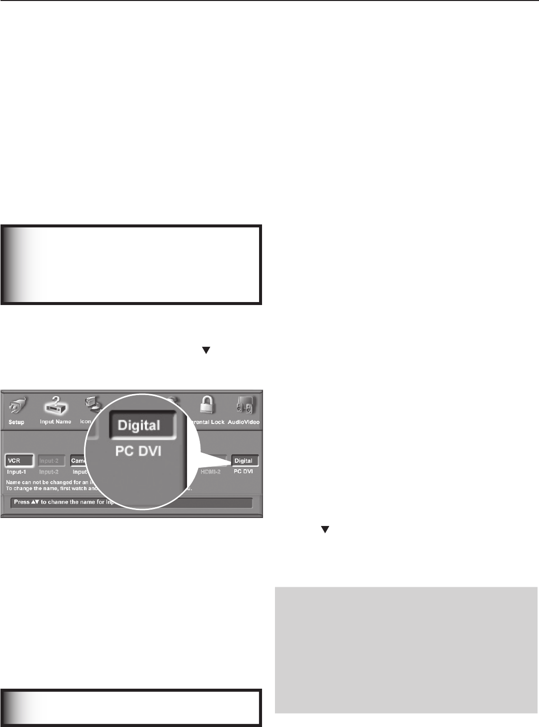
76 Chapter 6. Using the TV with a Personal Computer
Setup
1. See the TV specifications in Appendix B to confirm that
your computer video signal is compatible with the TV.
2. Note whether the computer supplies a digital or
analog video signal. You will need this information
during the setup procedure.
• Digital video signal: Comes from the computer’s
DVI or HDMI output.
• Analog video signal: Comes from the computer’s
VGA 15-pin output and requires a VGA-to-DVI
cable or a VGA cable and VGA/DVI adapter.
3. Power on the TV.
IMPORTANT
In the next step, select the correct video signal
type (analog or digital) in the Input Name menu.
Otherwise, the TV will be unable to display a
picture from the computer.
4. Press
MENU
to open the Main menu, highlight the Input
Name icon and press
ENTER
.
5. Highlight the PC-DVI text box and press to change
the setting to match your computer’s video signal
type, either Digital or Analog.
Figure 1. Specify your computer’s video signal type
(analog or digital) in the Input Name menu.
6. Press
EXIT
to close all menus.
7. Connect the computer’s video output to the TV’s PC-
DVI jack. See the connection diagrams in this chapter
to find the method best suited to your equipment.
8. Connect the computer’s audio output using one of
these options:
• Connect analog left/right audio to the TV’s
PC -DVI AUDIO
jack.
• If your computer offers digital audio output,
connect it to a digital A/V receiver instead.
IMPORTANT
See Appendix B for signal compatibility.
Video Adjustments
1. Power on the computer if it is not already on.
2. Select PC from the Input Selection menu. To do this,
press
INPUT
to open the Input Selection menu, move the
highlight to the PC icon, and press
ENTER.
3. Change the resolution of the computer image. The
goal is to maximize the computer resolution while
maintaining a suitable aspect ratio for the image. See
the explanation later in this chapter.
4. Perform TV video adjustments. Press
VIDEO
repeat-
edly to cycle through the video-adjustment options.
The following additional adjustments are available for
computer video:
Auto Position. Press
ENTER
to automatically center
the position of the PC video.
HorizPosition (Horizontal Position). Manually
adjust the horizontal position of the PC. This
selection overrides the Auto Position selection.
VertPosition (Vertical Position). Manually adjust
the vertical position of the PC. This selection
overrides the Auto Position selection.
Fine Detail (analog DVI-A signals only). Manually
adjust the picture quality of the PC. This selection
overrides the Auto Position selection.
5. Change the TV picture format to suit the image.
Press FORMAT to cycle through the available picture
formats. See the chart later in this chapter showing how
various computer resolutions are displayed on the TV.
To Remove the Computer Icon from
the Input Selection Menu
When you disconnect an analog video connection from
a personal computer, the computer icon remains in the
Input Selection menu until you remove it.
1. I
n the Input Name menu, highlight the PC DVI Input box.
2. Press to select Digital.
3. Press
EXIT
to close all menus.
The next time you open the Input Selection menu, the
computer icon will no longer appear.
Note
• The
PC-DVI
input on the TV can accept either
analog (DVI-A) or digital (DVI-D) signals.
• You must specify the PC-DVI setting in the Input
Name menu as either Analog or Digital, depend-
ing on the signal type sent by your computer.
• If your computer offers digital audio output, you
can connect your computer’s digital audio out to a
digital input on a digital A/V receiver.
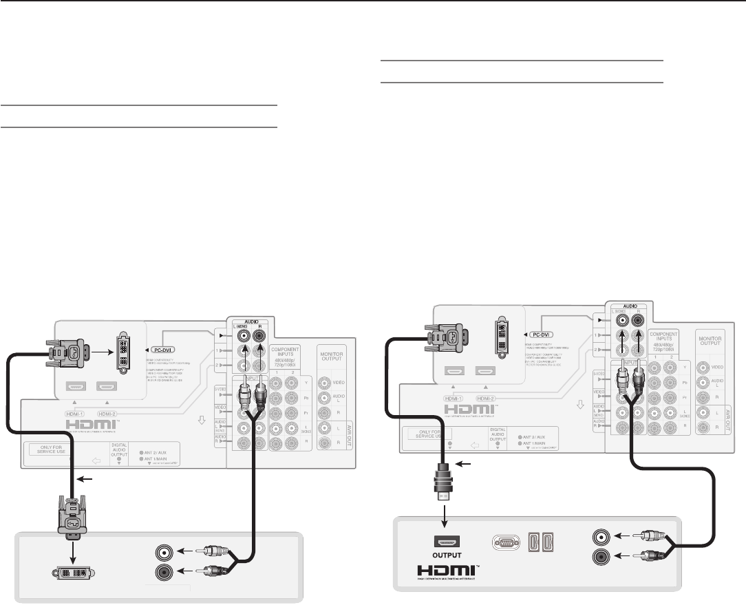
Chapter 6. Using the TV with a Personal Computer 77
Computer with HDMI Monitor Output
Required: HDMI-to-DVI cable or an HDMI cable with an
HDMI/DVI adapter, stereo audio cables
If the computer’s audio output is a single mini jack, a mini
audio-to-RCA-male “Y” adapter cable is also required.
1. Connect the computer’s
HDMI
output to the TV’s
PC-DVI
jack. Use either an HDMI-to-DVI cable or an
HDMI cable with an HDMI/DVI adapter.
2. Connect the left (white) and right (red) audio cables
from the computer’s
AUDIO OUT
to
PC-DVI
AUDIO
on the TV back panel.
Figure 3. Connecting a personal computer with an HDMI
monitor output
Connecting a Computer to the TV
Computer with DVI Monitor Output
Required: DVI-to-DVI cable, stereo audio cables
If the computer’s audio output is a single mini jack, a mini
audio-to-RCA-male “Y” adapter cable is also required.
1. Connect the DVI-to-DVI cable from the computer
DVI
output to the
PC-DVI
jack on the TV back panel.
2. Connect the left (white) and right (red) audio cables
from
AUDIO OUT
on the PC back panel to
PC-
DVI AUDIO
on the TV back panel.
Figure 2. Connecting a personal computer with DVI Monitor
Output
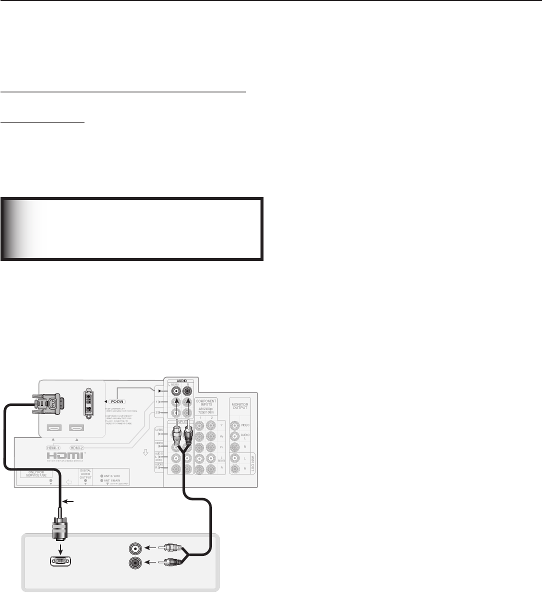
78 Chapter 6. Using the TV with a Personal Computer
Computer with VGA 15-Pin Monitor Output
(Analog Video)
Required: 15-pin computer VGA-to-DVI cable or a VGA
computer cable and a DVI/VGA adapter, stereo audio
cable.
If the computer’s audio output is a single mini jack, a mini
audio-to-RCA-male “Y” adapter cable is also required.
IMPORTANT
To use this connection, you must first select the
Analog setting in the PC DVI box of the Input
Name menu. See the “Setup” section for more.
1. Connect the computer’s
PC MONITOR OUT
to
PC-DVI
on the TV back panel. Use either a VGA-to-
DVI monitor cable or a VGA computer cable with a
VGA/DVI adapter.
2. Connect the left (white) and right (red) audio cables
from the computer’s analog audio ouput to
PC-DVI
AUDIO
on the TV back panel.
Figure 4. Connecting a computer with a VGA 15-pin monitor
output.
Connecting a Computer to the TV,
continued
Chapter 6. Using the TV with a Personal Computer 79
Adjusting Image Resolution
Your Mitsubishi TV can display resolutions from standard
VGA (640 x 480) through 1920 x 1080 signals at a refresh
rate of 60 Hz. Note that 1280 x 1024 and 1920 x 1080
signals are supported only for digital computer signals,
and 1920 x 1080 at 24, 30, and 60 Hz. See Appendix B in
this book for more on compatible screen resolutions.
In most cases, the computer will select the best resolution
match to display on the TV. You can override this setting
if you wish. The instructions below are for setting the
resolution on most personal computers.
1. In the PC’s Start menu, select Settings.
2. Select Control Panel.
3. Select Display.
4. Choose the Settings tab.
5. Change the resolution to the highest resolution with
the aspect ratio best suited for the image. See the
table on the next page showing possible PC formats.
Depending on your computer’s operating system,
adjust the resolution with either:
• the Screen area slider.
• the Screen Resolution slider
6. To change the refresh rate, click on the Advanced
button.
NOTE: Whenever the TV is powered on, the lamp is in
use, even if the TV screen appears dark. As a
reminder that the TV is powered on and that time
is being added to the lamp’s elapsed hours, set
the computer’s screen saver to a pattern that will
display after several minutes of inactivity.
Figure 5. Computer resolution, XGA selection
7. On the Monitor tab, select a setting from the Screen
refresh rate drop-down list. The resolution of 1920 x
1080 is supported at 24, 30, and 60 Hz; other resolu-
tions are supported at 60 Hz.
You may need to restart the computer for this change to
take effect.
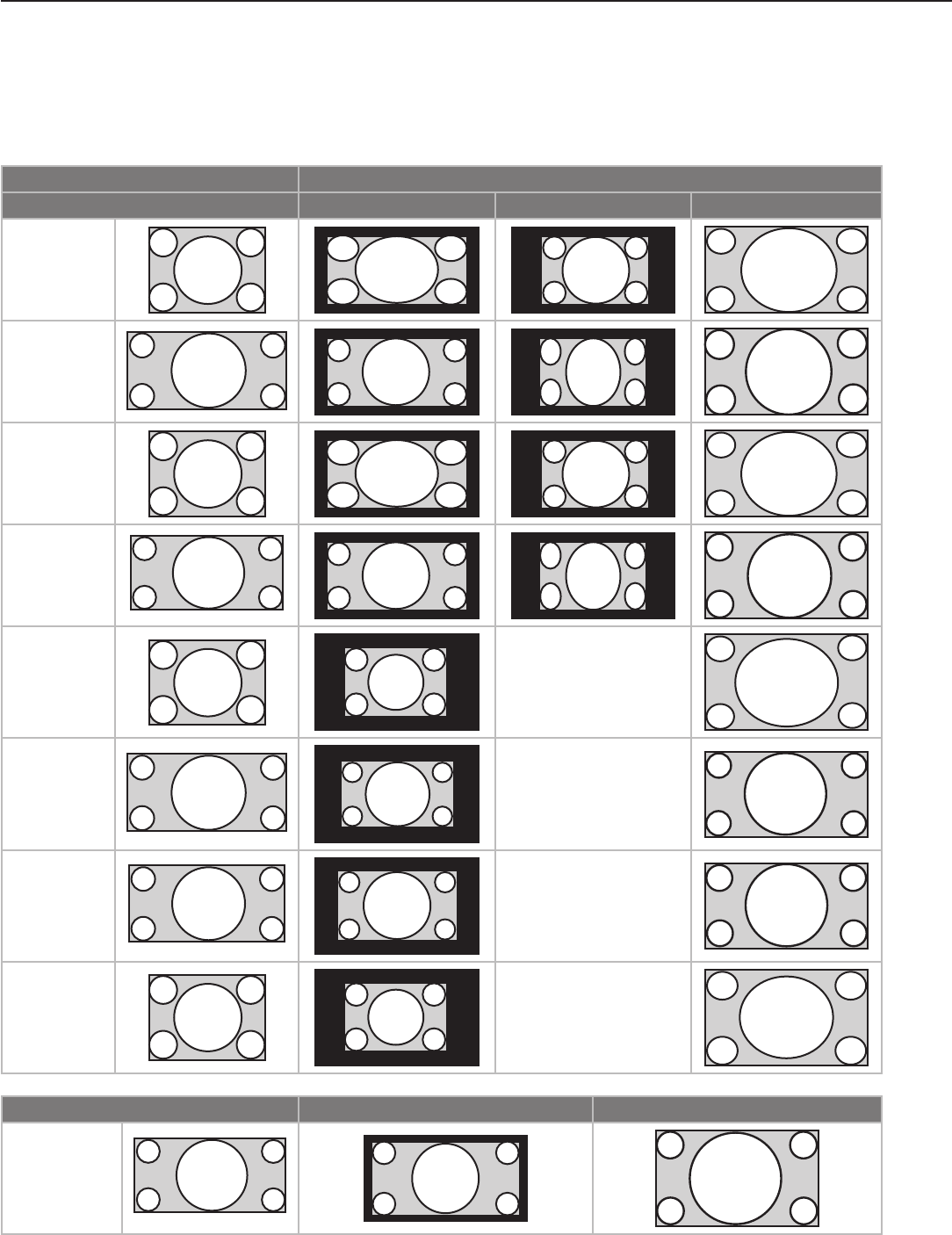
80 Chapter 6. Using the TV with a Personal Computer
Computer Display Formats Repeatedly press the
FORMAT
key to cycle through the TV
displays available for your computer’s video signal.
Computer Signal As Displayed on TV Screen
Format 16 X 9 Standard 4 X 3 Standard Zoom
VGA
640 X 480
WVGA
848 X 480
SVGA
800 X 600
WSVGA
1064 X 600
XGA
1024 X 768
PC 720p
1280 X 720
WXGA
1365 X 768
SXGA
1280 X 1024
(DVI-D signals
only)
Format Reduced Standard
PC 1080p
1920 X 1080
(DVI-D signals
only)

7
Using IEEE 1394 Devices
Overview ......................................... 82
Recording to IEEE 1394 Recordable Devices ................ 84
The TV Remote Control and IEEE 1394 Devices .............. 86
A/V Discs ......................................... 87
Switching Between Analog and Digital IEEE 1394 Outputs ...... 88
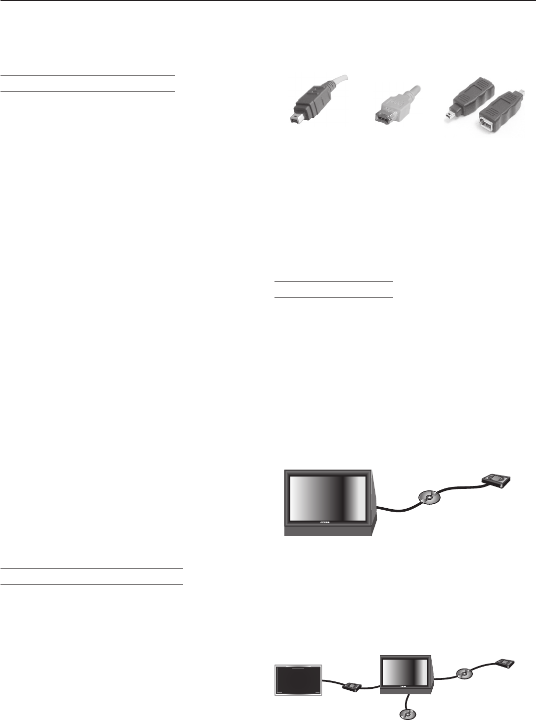
82 Chapter 7. Using IEEE 1394 Devices
Overview
Compatible IEEE 1394 Devices
Compatible A/V devices include some, but not all, cable
boxes, D-VHS VCRs, A/V discs, and future products.
Some devices may have IEEE 1394 connectors but are not
compatible with the TV. Areas of compatibility to consider
are:
1. Digital Video Signals
The TV can decode MPEG2 video as provided by cable
boxes and some camcorders. Many camcorders provide
DV video, which the TV cannot decode. Connect a DV
camcorder to the TV using analog audio plus composite
video, S-video, or component video, or use HDMI audio/
video. Other types of digital video, such as PC video
provided by some computers, must be decoded by the
source device and sent to the TV as analog video, S-video,
or DVI/HDMI video.
2. Digital Audio Signals
When received with video signals, the TV can decode
Dolby Digital signals and MPEG audio signals. Other
types of digital audio as provided by some digital record-
ing devices, such as DTS audio, cannot be decoded by
the TV when received over IEEE 1394 connections.
The TV may not be able to pass incompatible digital audio
signals on the coaxial digital audio output. These signals
may pass to other devices, however, on the IEEE 1394 cable.
3. Digital Control Signal
The TV can serve as the control center for IEEE 1394
audio/video devices, such as VCRs, A/V Discs, tuners,
cable boxes, and amplifiers that are compatible with the
following IEEE 1394 control standards.
• EIA-775. Designed for tuning devices such as cable
boxes, allowing the device to send simple graph-
ics. This standard does not, however, allow the TV to
control the cable box by IEEE 1394.
• AV/C (Audio Video Control). Designed to provide
basic controls such as play, stop, channel selection,
and volume, as appropriate for the device.
Four-Pin and 6-Pin Connections
There are two different types of connectors used for IEEE
1394 terminals and cables: a 4-pin and a 6-pin type.
Both types send the same digital audio, video, and control
signals, but the 6-pin connectors can also supply low-
voltage electrical power to connected devices. This TV
uses only 4-pin type connectors.
A 6-pin connector cannot be connected directly to a 4-pin
jack, and vice versa. To connect a 6-pin device to a 4-pin
device, use a 6-pin-to-4-pin adapter or adapter cable.
These cables are available from electronics and computer
stores.
4-pin connector 6-pin connector
6-pin-to-4-pin adapter
If you wish to connect a 6-pin device to the TV (such as a
camcorder), and the device is designed to receive electri-
cal power from another 6-pin device, there are several
ways to provide electrical power to the device:
• Connect the camcorder directly to the household AC.
• Use the camcorder’s battery for power.
• Connect the camcorder directly to another 6-pin
device in the network that can provide power.
Connection Methods
There are two connection methods for IEEE 1394 devices. Use
the method that fits your network of audio/video products.
Direct Device-To-Device Method
The IEEE 1394 interface allows you to chain devices,
unlike audio and video connections that require you to
connect each individual device directly to the TV. For
example, you can connect your D-VHS to your 1394 A/V
disc and then connect the 1394 A/V disc to the TV. The
resulting IEEE 1394 chain allows you to add more devices
to the chain. You will see an icon for each device in the
TV’s Input Selection menu and can also send information
from any IEEE 1394 device to other compatible devices.
Hub Connection Method
The IEEE 1394 standard allows you to use the TV as a hub
within the audio/video network. Each device can send
information, which may include audio and video, to any
other device in the network.
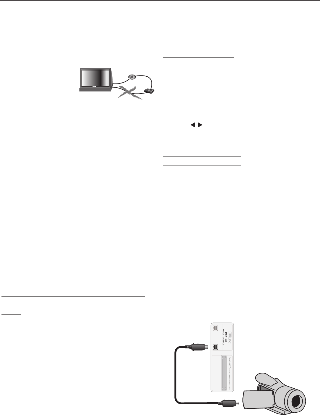
Chapter 7. Using IEEE 1394 Devices 83
IEEE 1394 Devices and the Input Selection
Menu
Select an IEEE 1394 device to watch from the Input Selec-
tion menu just as you would any other device. See figure
3, Input Selection menu.
When you connect an IEEE 1394 device to the TV network
and power it on, the new device is automatically detected.
Some non-audio/video or incompatible IEEE 1394
devices, such as personal computers (PCs), may not be
detected by the TV and do not appear in the Input Selec-
tion menu. Such devices can, however, coexist and are
still available to other devices on the IEEE 1394 network
that are compatible with these non-audio/video devices.
Some devices may be a combination of two or more types
of devices, such as a recording device that is also a tuning
device. Each portion of the device is called a sub-unit.
When you select a device on the Input Selection menu
Overview, continued
Tips for Connecting IEEE 1394 Devices
• Do not loop the last
device in the chain back
to the TV. When the
device chain is looped,
the TV may not be able
to work with the other
devices.
• Place devices that have only a mechanical (two-posi-
tion) power switch at the end of the chain or leave the
power switch in the on position. When turned off,
IEEE 1394 signals may not be able to pass through the
device to other devices.
• Place devices with the slowest communication speed
at the end of the chain. Sometimes the communica-
tion speed is marked near the IEEE 1394 connector
with an “S” number. The higher the number, the faster
the communication speed. This TV has a communica-
tion speed of s400. Devices with slow communica-
tion speeds can interfere with IEEE 1394 signals from
faster devices. When setting up a digital recording
between a faster device and a slower device, make
the slower device the source and make the faster
device the recorder.
• Use IEEE 1394 cables 15 feet or less in length
between devices.
• This TV is an IEEE 1394a device. It can be used with
an IEEE 1394b system when an IEEE-1394a-to-1394b
convertor is used. 1394b systems are capable of
greater distances and multi-room applications.
• The TV can recognize a maximum of seven IEEE 1394
devices.
that has sub-units, a pop-up menu will appear to allow
you to select the sub-unit you wish to use.
IEEE 1394 Amplifiers
You can use the TV to control switching between the TV
speakers and speakers connected to your IEEE 1394
amplifier.
1. Press
INPUT
to open the Input Selection menu. The
screen will show an icon for a connected IEEE 1394
amplifier. If an IEEE 1394 amplifier has been con-
nected, AVR and TV speaker icons will display.
2. Press
AUDIO
to move the highlight to the audio section.
3. Press
to select either the TV speakers or the IEEE
1394 amplifier.
4. Press
ENTER
to select and hear the new audio source.
IEEE 1394 Camcorders
• Control Functions. Connect the camcorder to the
TV’s IEEE 1394 jack on the rear of the TV and test
using the TV’s remote control to operate the cam-
corder. If your model does not operate properly, use
the camcorder’s control buttons instead.
• MPEG Camcorder. If you are unable to play back
over the IEEE 1394 interface, use the analog audio/
video connections described in chapter 2, “TV Con-
nections.”
• DV Camcorder. Connect the camcorder using the
analog audio and video connections described in
chapter 2, “TV Connections.”
You can connect an IEEE 1394 camcorder with an IEEE
1394 cable or with analog audio/video cables. In either
case, test using the TV’s remote control to operate the
camcorder over the IEEE 1394 cable.
84 Chapter 7. Using IEEE 1394 Devices
Recording to IEEE 1394 Recordable
Devices
You can use the TV to control recording to IEEE 1394
devices. While recording, you can view a program on a
different input or power off the TV. The following table
lets you see what signals can be recorded to an IEEE 1394
digital VCR or A/V disc.
Recording
Availability
Signal Type TV Input
Can be
recorded
Digital channels,
including high-defini-
tion channels
ANT 1, ANT 2
Digital signals,
including high-
definition signals
IEEE 1394 devices
Cannot be
recorded
Analog channels
ANT 1, ANT 2
Analog signals
INPUT 1
-
3
,
COM-
PONENT 1
and
2
Digital signals
HDMI 1
and
2
,
PC-DVI
Summary of signal inputs and recording to an IEEE 1394
digital VCR or A/V disc.
There are two ways to record digital content to an IEEE
1394 recordable A/V disc or DVCR:
• From the TV’s Recording Setup menu
• From the TV’s ChannelView™ channel guide
Immediate Recording from the Recording
Setup Menu
Recording Now from the Menu
1. Press (
RECORD
) to open the Recording Setup menu.
Figure 1. The Recording Setup menu
2. Review the recording setup information. Move the
highlight to each box you need to change.
• With the leftmost icon highlighted (the source),
press to change the source input if needed.
• Channel.
If the source is an antenna, select a
memorized digital channel using
,
CH
/ , or
enter the channel number from the remote control.
• Record To. If you have more than one recordable
IEEE 1394 device connected, use to select it
from the list in the Record To box.
• Duration. Use to select a recording dura-
tion of from 30 minutes to six hours in 30-minute
increments. The default is one hour.
3. Press a second time to start recording.
Time-Delayed Recording from the Menu
1. Ensure that TV Energy Mode is set to Fast Power On
and the TV clock is set to the correct time and day.
See “Setup Menu” to make changes.
2. Press (
RECORD
) to open the Recording Setup menu.
3. Review the recording setup information. To change
the source, recording device, or duration, follow the
steps described above under “Recording Now.”
4. Specify when to start the recording.
• Start Time
a. With the hour highlighted in gold characters,
press to select the hour, including AM or
PM. Press
ENTER
to move the highlight to the
minutes.
b. With the minutes highlighted, press to
select the minutes.
• Day. Use to select a day of the week.
5. Select Add and press
ENTER
to add the recording to
the Record List. A confirmation message will be
displayed if your selection is successful. If you pick
overlapping times, day(s), or destination devices, you
will see a message stating there is a conflict.
6. While the Recording Setup menu is displayed, press
GUIDE
to view a list of scheduled recordings and verify
the addition of the recording to the Record List, figure
2.
7. From the Record List you can:
• Press
GUIDE
to return to the Recording Setup menu.
• Press
EXIT
to return to TV viewing,
Figure 2. Record List screen. From the Record menu,
press GUIDE to open the Record List to review or cancel
scheduled recordings.
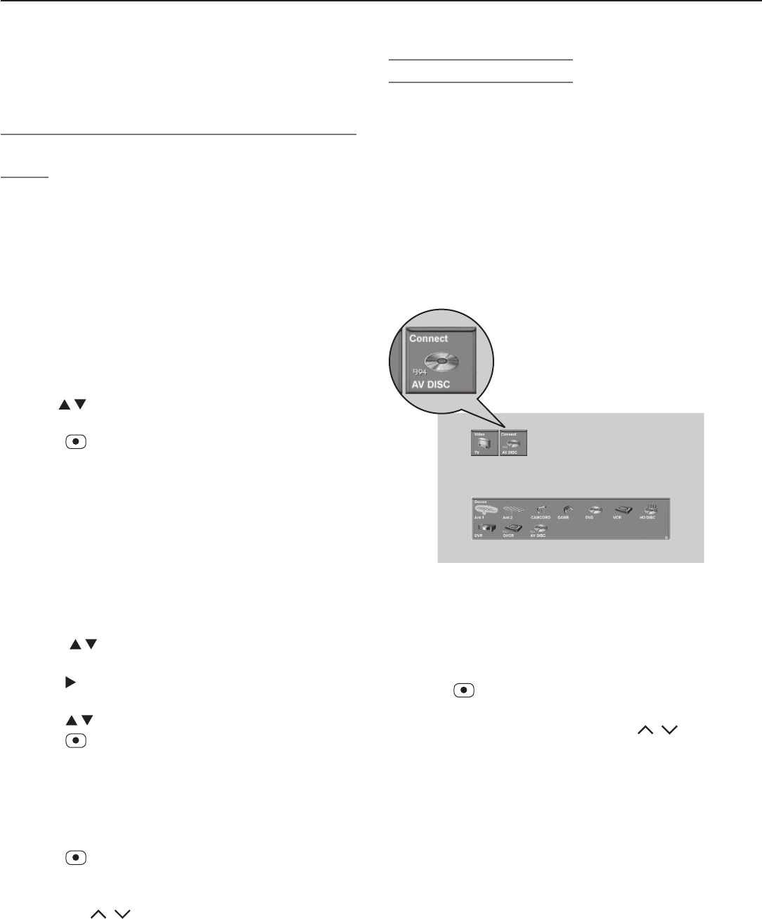
Chapter 7. Using IEEE 1394 Devices 85
Recording from the ChannelView™ Channel
Guide
ChannelView provides program listings, as sent by the
broadcasters, for memorized channels on
ANT 1
and
ANT 2
. Press the
GUIDE
key while watching
ANT 1
or
ANT 2
to view ChannelView listings and to set up imme-
diate or future recordings as described here.
Immediate Recording from ChannelView
1. Press
INPUT
to open the Input Selection menu. High-
light an
ANT 1
or
ANT 2
program source and press
ENTER
.
2. Press
GUIDE
to open the ChannelView channel guide for
the current input.
3. Use to highlight the digital channel and program
you wish to record from the list of channels.
4. Press (
RECORD
).
A red “R” temporarily displays next to the program
listing to indicate the program will be recorded.
5. Press
EXIT
to return to TV viewing.
Time-Delayed Recording from ChannelView
Set Up the Recording
1. Ensure that TV Energy Mode is set to Fast Power On
and the TV clock is set to the correct time and day.
See “Setup Menu” in chapter 4, “TV Menu Settings.”
2. Perform steps 1 and 2 described above.
3 Press to highlight the source channel you wish to
record from.
4. Press to view a list of future programs on that
channel.
5. Press to highlight a future program.
6. Press (
RECORD
).
A red “R” temporarily displays next to the program
listing to indicate the program will be recorded.
You can schedule a maximum of 32 recordings.
7. Press
EXIT
to close the menu.
Confirm the Recording Setup
1. Press (
RECORD
) to open the Record menu.
2.
Press GUIDE to open the Record List (figure 2, on the
previous
page) and view all scheduled recordings.
Press CH / to page quickly through the list.
3. Verify that the program you wish to record appears in
the list.
4. Press
EXIT
to close the menu.
Recording to IEEE 1394 Recordable
Devices, continued
Cancelling Recordings
To Cancel a Recording in Progress
1. Press
INPUT
to open the Input Selection menu.
2. Move the highlight to the source input icon. There is
no need to press
ENTER
.
The Input Selection menu displays an icon for an
active recording connection to a recordable IEEE 1394
device. See the IEEE 1394 connection icon in figure 3.
3. Press
CANCEL
. The connection icon will disappear to
indicate termination of the recording connection.
4. Press
EXIT
to return to TV viewing.
Connection
Icon
Figure 3. The Input Selection menu displays specialized
icons for IEEE 1394 devices.
The audio icons are displayed (in the upper right corner)
only when an IEEE 1394 amplifier is connected.
To Cancel a Scheduled Recording
1. Press (
RECORD
) to open the Record menu.
2. Press
GUIDE
to open the Record List (figure 2) and view
all scheduled recordings. Press
CH
/ to page
quickly through the list.
3. Highlight the program you wish to remove from the
Record List and press
CANCEL
.
4. Press
EXIT
to close the menu.
86 Chapter 7. Using IEEE 1394 Devices
The TV Remote Control and IEEE
1394 Devices
If the 1394 cable box or satellite receiver provides guide
information for 1394 content:
• For compatible satellite receivers and some cable
boxes, the TV remote control
GUIDE
key displays the
on-screen programming guide for the receiver or cable
box. Press and
ENTER
to navigate the dis-
played program guide.
• For satellite receivers, you may also be able to use the
numbers or other additional buttons.
• For an IEEE 1394 cable box or satellite receiver, you
can also try using the
CABLE/SAT
position of the TV
remote control to see if it can operate the device. If
not, use the remote control that came with the device.
Operation of IEEE 1394 Devices with the TV’s Remote Control
(slide switch set to TV position)
Device
CABLE/SAT A/V DISC DVCR
AMPLIFIER
(some MPEG2 models
only)
Remote Con-
trol Key
POWER
Power the device on/off when highlighted in the Input selection menu. See the instructions above.
CH /
Channel up/down Page up/down
(when track list is displayed)
Index search forward/
reverse
(if supported by DVCR)
VOL /
Volume Up/Down
MUTE
Mute On/Off
0-9 (DIGITS)
Number functions Search by time
(when followed by
ENTER
)
QV
Last Channel Recall
EXIT
Exit menus/displays Exit menus/displays Exit menus/displays
ENTER
Enter or select Enter or select Enter or select
CANCEL
Cancel function Delete recording from Track List Cancel function or
counter reset
GUIDE
Digital-channel guide
(may need to press
twice)
Display Track List.
Up/down/left/right
Skip Forward 30 seconds during
playback
Skip Backwards 12 seconds during
playback
Skip to end or beginning of program
Up/down in track list
Up/down/left/right
PLAY
Play Play
STOP
Stop Stop
RECORD
Record Record
REV
Reverse picture scan or Slow Play Reverse or Slow Play
FFWD
Fast picture scan or Fast Play Fast Play
PAUSE
Pause Pause
To Power On or Off a Compatible IEEE 1394
Device
1. Press
INPUT
to open the Input Selection menu.
2. Move the highlight to the icon for the device. There is
no need to press
ENTER
.
3. Press
POWER
.
4. Press
EXIT
to return to TV viewing.
Or: press
ENTER
to switch to the highlighted device.
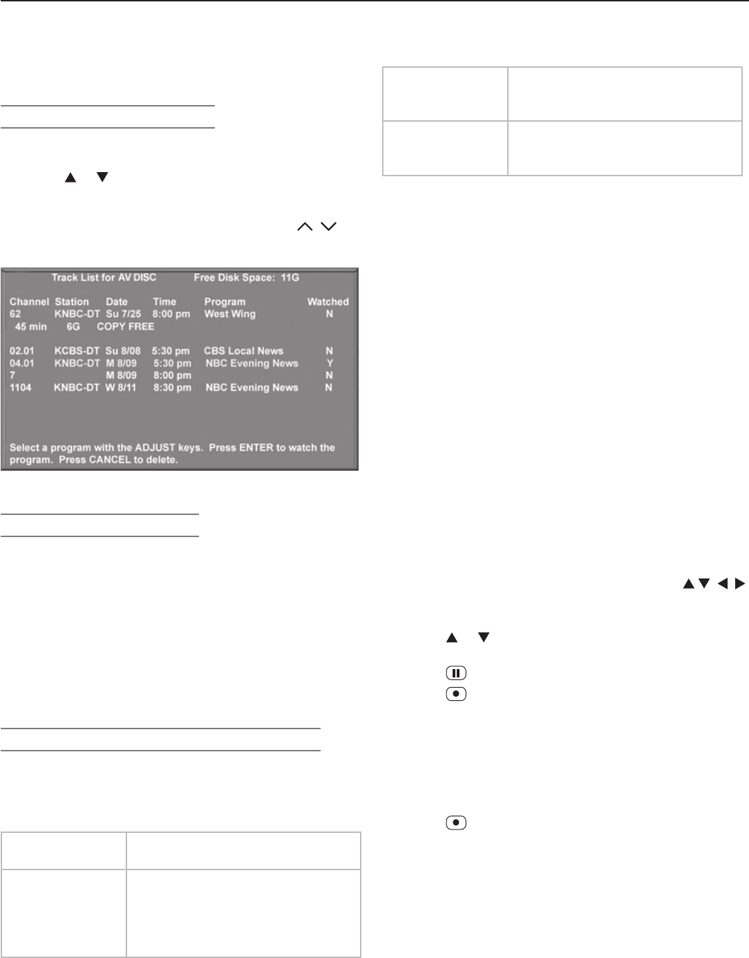
Chapter 7. Using IEEE 1394 Devices 87
Copying or Moving A/V Disc Recordings
Tracks you record to disc may have copy restrictions
assigned to them. To learn a track’s copy status, high-
light the track in the Track List and press
INFO
. Tracks are
assigned one of these ratings:
Copy Free
(or no status shown)
No copy restrictions apply.
Copy Never The track cannot be transferred to
another recording device. Tracks
of this type may have an assigned
retention period. See below for
more information.
Copy Never,
Movable
You can transfer the track to a dif-
ferent recording device. The track
on disc is deleted as it is moved.
Copy No More No more recordings are allowed.
You have already recorded from
another source.
Retention Period
Some
COPY NEVER tracks have a retention period
assigned by the content provider. The retention period
is the length of time you can keep and view the record-
ing. The initial retention period, if any, is shown next to
the copy status in the Track List
INFO
display (see figure 4).
To check how much time remains of the retention period,
start viewing the recording and press
INFO
.
Note: The retention period for all tracks on the disc
expires if there is any loss of power to the TV, even
momentary. For example, expiration of the reten-
tion period will occur if you:
• Unplug the TV from the AC power source.
• Experience a power outage or power
fluctuation.
Remember that you can safely turn off TV power
using the
POWER
button without affecting the reten-
tion period.
To Copy or Move a Track to Another IEEE
1394 Device
1. Press
INPUT
on the remote control and press
to select the source A/V disc. Press
ENTER
to open the
Track List.
2. Press or to select a track. Then press
ENTER
to
start playback.
3. Press (
PAUSE
) to pause playback.
4. Press (
RECORD
) on the TV remote. The Record
menu will display.
5. In the Record To section, review the destination
device (A/V Disc, DVCR). Change if necessary. If
moving, leave the other settings unchanged.
6. Set the duration to the length of the original track or
longer.
7. Press a second time to start recording.
A/V Disc Search by Time
While playing an IEEE 1394 A/V disc you can search to a
specific time in the recording.
1. Start playing the desired track on the A/V disc.
2. Use the number buttons to enter the time code posi-
tion of hours followed by minutes. For example, to
enter one hour and twenty-two minutes (1:22) into the
track, enter
1
,
2
,
2
.
3. Press
ENTER
to skip to the time code position. To
cancel the request or to start over, press
CANCEL
instead of
ENTER
.
A/V Discs
A/V Disc Track List Screen
When viewing an A/V Disc:
• Press
GUIDE
to display its Track List (see figure below).
• Press or to navigate through the Track List.
• To play a track, select it on the list, then press
ENTER
.
• Press
INFO
to view details for a highlighted track.
• To move through listings quickly, press
PAGE
/ .
• To delete a track, highlight it and press
CANCEL
.
Figure 4. A/V Disc Track List screen
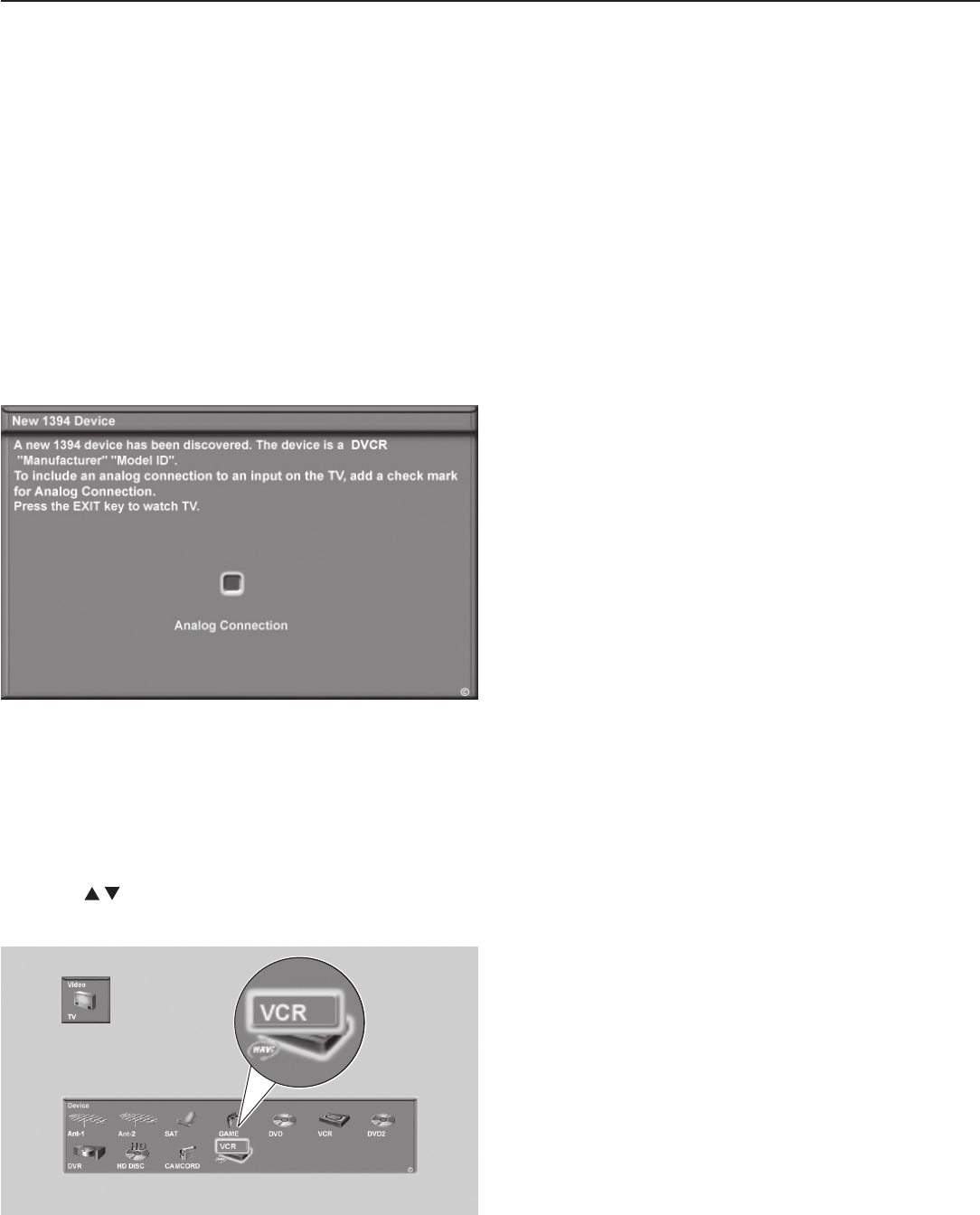
88 Chapter 7. Using IEEE 1394 Devices
Switching Between Analog and
Digital IEEE 1394 Outputs for the
Same Device
To enable switching between analog and digital outputs
for the same device, you must have check-marked the
Analog Connection box when the New 1394 Device
screen displayed when you first connected the device.
See the section “Before You Begin” in chapter 2, “TV
Connections.”
Figure 5. The ClearThought Auto Input sensing screen
for IEEE 1394 devices. Place a check in the Analog
Connection box if your device has both analog and digital
outputs.
1. Press
INPUT
to display the Input Selection menu.
2. Highlight the icon for the IEEE 1394 device and press
ENTER
.
3. Press to switch between icons representing the
analog and digital outputs of the device. See figure 6.
Figure 6. The Input Selection menu shows icons for the
analog and digital outputs of the IEEE 1394 device.
4. Press
ENTER
to select the device output.

Appendices
Appendix A: Bypassing the Parental Lock ................. 91
Appendix B: Specifications ............................ 93
Appendix C: Troubleshooting .......................... 95
Appendices 91
Lock Bypass Instructions Have Been Filed for
Future Reference
IMPORTANT
Cut along the dotted line and file bypass
instructions in a safe place for future
reference.
Appendix A: Bypassing the
Parental Lock
Bypassing the Parental Lock
After you set the lock, you must use your pass code to
view a locked program, view the locked TV, cancel the
lock, or enter the Parental Lock menus.
If you forget your pass code, you can view the locked TV
without entering your pass code. When you are prompted
for your pass code, press the number
9
and
QV
buttons
on the TV remote control at the same time. This process
temporarily unlocks the TV
When entering the Parental Lock menu, this process
deletes your old pass code and prompts you to enter a
new pass code.
• You can either enter a new pass code to open the
Parental Lock menu and make changes or press
EXIT
to close the menu.
• If any of the locks are turned on and you exit the
menus when prompted for a new code, the old code
and all lock settings are retained.
• If all locks are turned off and you exit the menus when
prompted for a new code, then the previous code is
erased.
IMPORTANT
When changing or deleting your pass code,
you must use the remote control included
with this TV. You cannot use a Mitsubishi
remote control from another component or a
“universal” remote.

92 Appendices
This page intentionally left blank

Appendices 93
Appendix B: Specifications
Picture Technology
LCD Screen
Color active matrix LCD 1920 x 1080 dots
Backlight
LT-37131: Direct Type 18 CCFTs ; LT-46131: Direct Type 24 CCFTs
Reception
Channel Frequency Reception
Over-the-Air: VHF 2–13, UHF 14–69
Analog Cable: 1–125
Digital Cable: 1–135
Channel Type*
Over the Air: Analog NTSC, Digital ATSC with sub-channels
(all 18 video formats)
Cable: Analog NTSC (non-scrambled)
Digital QAM 64 and 256 with sub-channels (non-scrambled)
CableCARD™:
(LT-37131, LT-46131)
Authorized scrambled and non-scrambled digital channels
* Note for Digital Channels: The channel numbers displayed on screen are determined by the broadcaster or cable company and can vary
from the standard frequency number. If there is no channel-number information provided by the broadcaster or cable company, the TV
creates a channel number. The created channel number uses the frequency number as the main channel number and the program number
as the sub-channel number. When using an authorized CableCARD, the channel numbers are determined by the cable company.
Inputs
Description Qty. Signal Type Input Specifications
Antenna/Cable input 2 RF F connector, 75-ohm
HDMI (digital video/audio) 2HDMI EIA-861B standard
for digital audio and video
HDMI standard connector
Video: 60 Hz: 480i, 480p, 720p, 1080i
24 Hz, 30 Hz, 60 Hz: 1080p
Audio: PCM stereo
Note: Not for use with personal computers.
Video/S-Video
(one front, two rear) 3 NTSC 480i only
Video: RCA Pin Plug, 1.0 V p-p, 75 ohm
S-Video: Four-Pin DIN Plug
Y: 1.0 Vp-p 75-ohm
C: 0.286 Vp-p (burst signal), 75-ohm
Component Video (Y/Pr/Pb) 2
EIA-770.1 & EIA 770.2
480i, 480p, EIA 770.3
720p and 1080i (video
standards)
RCA Pin Plug (EIA-770.3 Standard Levels and
Timing)
Y: 1.0 Vp-p (includes sync), 75-ohm
Pr: 700 mV p-p, 75-ohm
Pb: 700 mV p-p, 75-ohm
Audio Inputs 8
pairs analog left and right audio RCA Pin Plug 500 mV (full scale), 43-k ohm
PC DVI-I Input 1 analog and digital video VGA (640 x 480, 60 Hz)
W-VGA (848 x 480, 60 Hz)
SVGA (800 x 600, 60 Hz)
W-SVGA (1064 x 600, 60 Hz)
XGA (1024 x 768, 60 Hz)
1280 x 720, 60 Hz
digital video only SXGA (1280 x 1024, 60 Hz)
1920 x 1080 (24 Hz, 30 Hz, 60 Hz)
WXGA (1360 x 768, 60 Hz)
94 Appendices
Appendix B: Specifications, continued
IEEE 1394 System Compatibility
• This television is designed to conform to IEEE 1394 AV/C Software standards in effect at the time of development.
This networking and control technology is designed to provide high-performance digital connections and product
control, making the product easier to use.
• Mitsubishi D-VHS VCRs are fully compatible with this TV in audio, video, and control.
• As other manufacturers distribute products that use the IEEE 1394 AV/C standards, they will be responsible for
developing products that meet the standards of the technology, as well as compatibility testing with other products.
Mitsubishi cannot be responsible for their efforts, and therefore cannot promise compatibility with these other prod-
ucts. Any compatibility problems with other manufacturers’ products should be brought to the attention of those
manufacturers.
HDMI
The HDMI input is compliant with EIA-861B standards for standard, extended, and high-definition video; digital audio,
and HDCP copy protection. The HDMI inputs on this TV are not intended for use with personal computers or devices
outputting video signals with computer resolutions.
Outputs
Description Qty. Output Specifications
Video 1Video: RCA Pin Plug 1.0 Vp-p, 75-ohm
Signal Type: NTSC 480i only
Audio (Signal) 2
pairs
RCA Pin Plug, 500 mV rms + 200 mV (full scale) for analog sources, 1.5
Vrms + 0.5 Vrms (full scale) for digital sources.
Audio (Speakers) 2 Woofers, 5.5" x 2.2"
Digital Interfaces
Digital Audio Output 1 RCA Pin Plug, Signal Type, Dolby Digital, PCM
IEEE 1394 (input/output)
(2 rear) 2 IEEE 1394 Four-Pin-Type Terminal, S400
Physical Characteristics and Power Consumption
Model Dimensions (inches) Weight Power Consumption
Height Width Depth
LT-37131 26.8 36.0 13.35 58.8 lbs. 250 w
LT-46131 31.7 44.6 15.59 89.0 lbs. 350 w
Enviornmental Condtions
Model Operating Temperature
LT-37131 41o F ~ 95o F (5o C ~ 35o C)
LT-46131 41o F ~ 95o F (5o C ~ 35o C)
Appendices 95
Appendix C: Troubleshooting
Reset Name When to Use How to Use Resulting Action
Demo Mode
Turn-Off
To turn off the retail demo
mode slide show.
1. While viewing the TV, press
MENU
to
display the TV Main menu with the
Setup icon highlighted.
2. Press
ENTER
to display the Setup menu.
3. When the Setup menu is displayed,
use to highlight the Demo Mode Off
button and press
ENTER
.
The demo mode will be turned off.
The Demo Mode Off button in
the setup menu will turn gray and
be unselectable. The demo mode
slide show cannot be turned on
again.
Format When the picture shape
seems incorrect, use
FORMAT
to change the
shape of the picture.
Press the
FORMAT
key to cycle through the
available formats to find the best format for
the current picture.
The last-used format for a signal
type is memorized for each input.
The next time the same input and
the same signal type is viewed, the
last-used format will be recalled.
PerfectColor™
(for the single
input currently
being watched)
When the color intensities
seem out of balance, use
PerfectColor resets to
reset the color balances
to the original factory
settings.
1. While viewing the input to be reset,
press
VIDEO
repeatedly to cycle to the
PerfectColor™ option.
2. Press
ENTER
to display the PerfectColor
menu.
3. Press
CANCEL
to reset the colors.
All PerfectColor sliders are reset
to the original center position.
The PefectColor settings for other
inputs remain unchanged.
A/V Memory
Reset
(for the single
input currently
being watched)
When audio and/or video
settings for a single input
seem incorrect, use A/V
Memory Reset to return
the input to the original
factory settings.
1. While viewing the input to be reset,
press
MENU
to display the TV Main
menu.
2. Use to highlight the Audio/Video icon
and press
ENTER
.
3.
When the Audio/Video menu is displayed
with the AV Memory Reset text box high-
lighted, press
ENTER
to reset.
4. Press
EXIT
to exit the menu.
All Audio and Video settings for the
individual input are reset except
for the Listen To, Language, Audio
Balance, and Closed Caption
settings.
A/V Reset
(for all inputs)
To reset audio and video
adjustments for all inputs
to the original factory
settings.
While viewing the TV, press the front panel
buttons
GUIDE
and
FORMAT
at the same time.
All Audio and Video settings are
returned to the original factory
settings, including Listen To and
Language, plus Closed Captions
settings and Format settings .
Channel
Memorization
To erase and re-
memorize channels on
ANT 1
or
ANT 2
.
1. While viewing the TV, press
MENU
to
display the TV Main menu with the
Setup icon highlighted.
2. Press
ENTER
to display the Setup menu.
3. When the Setup menu is displayed, use
to highlight the antenna and
reception mode button and press
ENTER
to start memorization.
All previously memorized channels
for the selected antenna input are
erased and a new set of memorized
channels is created. To add or
delete individual channels, see
the Channel Menu instructions in
chapter 4, “TV Menu Settings.”
TV Reset Functions
You can resolve many common TV problems using the
reset functions described in the following table. See also
the additional troubleshooting suggestions later in this
appendix.
IMPORTANT
Before you change sound or picture settings: If
picture or sound settings seem wrong for a broadcast
channel (a channel from
ANT 1
,
ANT 2
, a cable box,
or satellite receiver), first check other channels from the
same input before changing settings. If most other chan-
nels from the same input seem correct, there is likely a
problem with the broadcast rather than with the TV. Use
care in this case, as changes you make to fix problems on
individual channels also affect all other channels on the
same input.
96 Appendices
Reset Name When to Use How to Use Resulting Action
Parental Lock
Pass Code
To change your Parental
Lock Pass Code
T
his information is listed on the cutout page in
Appendix A. Please refer to that page.
Allows a new code to be
established.
Front-Panel Lock
Release
To re-enable the front-
panel controls after
activation of the Front-
Panel Lock
• When Energy Mode is set to Fast
Power On, press and hold the
MENU
button on the front panel for over eight
seconds.
• When Energy Mode is set to Low
Power, press
POWER
on the front panel to
turn on the TV. Press and hold the
MENU
button on the front panel for over eight
seconds.
Allows the front panel to be
unlocked if the remote control is
misplaced.
System Reset If the TV does not turn on
or off, does not respond
to the remote control or
front panel buttons, or
has audio but no video.
Press the
SYSTEM RESET
button on the front
panel with a pointed object such as the
point of pencil or end tip of a paperclip.
The TV will turn off and the green LED
will flash quickly for about one minute.
When the blue LED stops flashing,
you may turn on the TV. The changes
you made most recently, before using
SYSTEM RESET
, may be lost. Changes
you made previously, however, are
not lost.
TV Reset
IMPORTANT:
Use this reset
only if all other
resets have been
unsuccessful.
To reset all consumer-
accessible settings
and all memories to the
original factory defaults.
CAUTION: All owner-
performed setups and
adjustments will be
erased.
1. While viewing the TV, press
MENU
to
display the TV Main menu.
2. With the Main menu displayed, press
number keys 1 2 3 to display the
Reset Menu.
3. READ THE ON SCREEN WARNING
AND INSTRUCTIONS.
• If you do not wish to use this reset,
press
EXIT
or
MENU
to back out.
• If you do wish to use the reset,
press
ENTER
to erase all memories
and settings.
The TV will start the initialization
process. The TV will then turn off
and the front
blue
LED will start
flashing. When the LED stops
flashing, you can turn the TV on
again. The Parental Lock Access
code will remain unaffected, but
all other memories and settings
outlined in this Owner’s Guide will
need to be set again.
Service and Support
Service
If you are unable to correct a problem with your TV,
consult your Mitsubishi dealer or Mitsubishi Consumer
Relations at (800) 332-2119.
• DO NOT adjust any controls other than those
described in this Owner’s Guide.
• DO NOT remove the protective back cover of your
TV.
Support
• To order replacement or additional remote controls
or Owner’s Guides,
visit our website at www.mitsu-
parts.com or call (800) 553-7278.
• For questions:
Call Consumer Relations at 800-332-2119.
E-mail: MDEAservice@mdea.com
Website: www.mitsubishi-tv.com
Appendix C: Troubleshooting, continued
Appendices 97
Appendix C: Troubleshooting, continued
TV Channels
Symptom Remarks
1. The TV takes several seconds to respond to
channel changes.
• It is normal for digital channels to take longer to tune in.
• Press
ENTER
after a channel number to avoid delays.
• Use a 4-digit number for an over-the-air digital channel.
• Use a 6-digit number for digital cable channels if your cable
service is able to recognize 6-digit channel numbers.
2. You cannot access a channel. • Use number keys instead of CH / .
• Be sure the channel you want to view is in memory. See
“Channel Menu” in chapter 4, “TV Menu Settings.”
• Check that the TV is turned to the correct device or antenna
for that channel by pressing the
INPUT
button.
• Make sure the Parental Lock is off.
• If you cannot tune to a virtual digital channel even though the
TV has already memorized digital channels, tune to the actual
(physical) channel number used by the broadcaster. The
virtual channel will then be automatically added to memory.
3. Name options are not available for some
channels.
Only memorized analog channels can be named.
4. When ChannelView™ list is displayed, infor-
mation appears incomplete
Available information is sent from the broadcaster or cable pro-
vider. No other data is available.
General TV Operation
Symptom Remarks
1. The TV remote control does not work. • Check that the batteries are installed correctly.
• Check that the slide switch is set to TV.
•
Be no more than 20 feet from the TV when using the remote control.
• Program the remote control to operate the TV or other device
(see chapter 5).
2. TV does not respond to the remote control or
to front panel control and TV will not power
on or off.
Use the System Reset button.
3. When a device is selected from the Input
Selection menu, the screen is blue (no signal
source).
• Make sure the selected device is turned on.
• Begin play of the VCR.
4. Devices are grayed out in the Input Selec-
tion menu or the Split Screen Input Selection
menu.
• A recording is in progress. Cancel the recording to select the
device.
• PCs and HDMI 1080p devices cannot display in the Split
Screen sub-picture.
5.
You have forgotten your Parental Lock pass code.
See Appendix A, Bypassing the Parental Lock.
6. Rating restrictions are not working. Open the Parental Lock menu and:
• Verify that the U.S. Ratings or Other Ratings setting is On.
• Check the Lock Time/Unlock Time to check if rating restric-
tions are disabled.
• Rating restrictions apply only to content on ANT 1 and ANT 2,
INPUT 1–3, and IEEE 1394 inputs.
7. On-screen displays appear each time you
change a function.
Normal TV operation.
8. Cable provider needs information to start
CableCARD™ service.
On the remote control, press
MENU
and then enter the numbers
999 to display the Host ID and CableCARD™ ID information.
9.
The TV remote
POWER
button blinks five times.
Batteries in the remote control are low and should be replaced.
98 Appendices
Picture
Symptom Remarks
1. Picture does not look like a high-definition
picture.
Not all signals are high-definition signals. To receive high-defini-
tion programming from your cable or satellite provider, you must
subscribe to the provider’s high-definition service. Some over-
the-air broadcasts are in high-definition and can be received with
a high-quality antenna suited to your location.
2. Split Screen does not display a sub-picture. • Make sure the Parental Lock is off.
• Not all inputs can be displayed as a sub-picture.
3. CableCARD channel is not shown as Split
Screen sub-picture when CableCARD
channel is the main image.
CableCARD allows only one channel at a time to be used.
4. There is a large black or gray rectangle on
the screen.
The TV’s analog closed captioning has been set to “text” mode in
the Captions menu. Turn off because there is no text information
being broadcast.
5. You cannot view a picture when playing a
VHS tape.
Check your VCR’s owner’s guide for further troubleshooting.
6. When viewing a stopped VCR, white lines
are rolling on the screen.
• Turn off video mute for the VCR.
• Begin playing the tape.
• Change the VCR input to the antenna input.
Appendix C: Troubleshooting, continued
TV Power On/Off
Symptom Remarks
1. TV takes an excessively long time to power
on.
• When switched on, the TV needs time to boot up, just as a
computer does.
• TV Energy Mode is set to Low Power. To change TV Energy
Mode to Fast Power On: Press MENU, open the Setup menu,
highlight the Fast Power On radio button, press
ENTER
.
2. You cannot program the TV to turn on auto-
matically (Timer function)
• The TV may be locked.
• The clock may not be set.
• A time-delayed recording may have started.
• TV Energy Mode is set to Low Power. Change to Fast Power
On in Setup menu.
3. The TV will not turn on after being plugged
in.
If blue light on front panel is blinking, wait for at least one minute
for the light to turn off, then press
POWER
again.
4. TV turned itself off and the light on the front
panel started to blink.
• Momentary power fluctuation caused the TV to turn off to
prevent damage. Wait for the blue light to stop flashing and
turn on again.
• If the TV does not stay turned on, use the System Reset
button on the front panel. If this happens frequently, obtain
an AC line power conditioner/surge protector.
• An unusual digital signal may have been received, triggering a
protection circuit. Wait for the light to stop flashing and turn TV
on.
5 TV will not power off. Use the System Reset button.
Appendices 99
Sound
Symptom Remarks
1. There is no sound even when the
volume is turned up.
• Check if the
MUTE
button is on.
• The TV’s “Listen to:” setting may be set to SAP.
• Check that the TV Speakers setting is On in the Audio/Video menu.
• If using an IEEE 1394 amplifier, check audio source in Input Selection
menu.
•
Perform System Reset.
2. The sound does not match the screen
picture.
• The TV’s Listen to: setting may be set to SAP.
• If using stereo or A/V receiver speakers, check their input selec-
tion.
• If using stereo or A/V receiver, check that AUDIO OUTPUT LEFT/
RIGHT or DIGITAL AUDIO OUTPUT on TV’s back panel is con-
nected to the A/V receiver.
Appendix C: Troubleshooting, continued
IEEE 1394 Recording
Symptom Remarks
1. Program to be recorded was correctly
selected from ChannelView, however, incor-
rect program was recorded.
The broadcaster supplied program information that was incorrect
and/or was changed after a recording was added to the Record
List.
2. Incomplete ChannelView program recorded. Recording device may lack sufficient blank space to make a full
recording.
3. ChannelView program recording failed. • Connection and compatibility issues with IEEE 1394
(FireWire®) digital devices. This may include too many
Firewire devices in use at one time, or the recording device
not understanding the record command.
• Television lost power long enough to lose current clock time.
• TV energy Mode was set to Low Power. Change TV Energy
mode to Fast Power On. Press MENU, open the Setup menu,
highlight the Fast Power On radio button, press
ENTER
.
Picture
Symptom Remarks
9. DVCR analog/digital problems. If the tape is currently playing but no picture displays, there
may be a mismatch of the media with the display. Press
INPUT
to display the Input Selection menu. Press
ENTER
for the DVCR
device. If digital is selected, try analog, or if analog is selected, try
digital.
Indicators
Symptom Remarks
Status indicator light is a steady/flashing red.
Service is required. Contact your dealer or a Mitsubishi Autho-
rized Service Center to arrange for a service evaluation. Listings
of Mitsubishi Authorized Service locations can be obtained from
our web site, www.mitsubishi-tv.com or by calling 1-800-332-2119.
100 Appendices
IEEE 1394 Devices
Symptom Remarks
1. Excessive digital artifacts appear when
viewing an IEEE 1394 device.
• The IEEE 1394 cable is too long; 15 feet between devices is
the maximum.
• There may be a slow device in the middle of the IEEE 1394
network. Move the slow devices to the end so that connec-
tions for faster devices do not pass through them.
2. D-VHS recordings for digital cable have
drop-outs (loss of picture or sound), or no
playback.
Digital cable signals on IEEE 1394 can exceed the data rate stan-
dards supported by DVCR.
3. There is no audio and video from the IEEE
1394 device.
• The device is not turned on. Turn the device power on.
• No media (tape or disc) is inserted into the device.
• The media is blank (has no recording).
• The play command failed - Try pressing play again on the
device’s remote control or front panel.
• The device is already in use (for example, the device is cur-
rently recording).
• The source is copy-protected or violates copy protection.
• The device’s digital video signal is not supported by the TV,
as may be the case with an IEEE 1394 signal from a com-
puter. Use analog connections instead, if available.
• The device is not an audio/video device.
• Too many other devices are already communicating over IEEE
1394. Remove or stop some devices and try again.
4. The IEEE 1394 Device is no longer listed in
the Input Selection menu.
• The IEEE 1394 plug is disconnected or loose.
• The IEEE 1394 device has not been powered on. Turn on.
• The device has not been discovered.
• The device is not an audio/video device
IEEE 1394 Recording
Symptom Remarks
4. Cannot record to or from the IEEE 1394
device, including dubbed recordings.
• To initiate a recording to IEEE 1394 device, press the
(RECORD) key. The Record menu displays allowing setup of
the recording.
• The source device for the recording is not powered on.
• When dubbing, the destination device for the recording is not
powered on.
• The program is copy protected.
• The program has already been recorded once and the copy
protection only allows one recording.
• Unapproved source device for copy protected material.
• The recording device can not decode the copyright signal
included in the signal source (try another device if available).
• The playing device (for dubbing) does not support copy-
righted material.
• Source for recording is copyrighted
• Too many IEEE 1394 devices in network. Insufficient band-
width available. Disconnect unused devices.
• Source Device has higher speed (S 400) than record device.
If possible, reverse devices, play in the slower device and
record in the faster device.
Appendix C: Troubleshooting, continued

Appendices 101
Appendix C: Troubleshooting, continued
IEEE 1394 Devices
Symptom Remarks
5. The IEEE 1394 device cannot be selected (is
grayed out).
The device may be busy with a recording. Cancel the recording.
6. When the Input Selection Menu is displayed,
a menu does not display when I press the
MENU
button.
• The IEEE 1394 device does not provide a menu.
• The TV cannot support IEEE 1394 menus.
7. All IEEE 1394 devices disappear. • The connected devices must not be in a loop that returns to
the TV. Make sure a device is connected at the end.
• Disconnect all the cables and devices from the TV. Replace
them one by one to locate the problem device or cable.
• Use System Reset (front control panel).
8. Cannot rediscover a deleted IEEE 1394
device.
The device has been disconnected. Plug it in.
9. An IEEE 1394 device has been plugged in
but does not appear in the Input Selection
menu (not discovered).
• The IEEE 1394 connection to the TV or another device is not
secure or is loose.
• The IEEE 1394 device is not powered on.
• A device in the IEEE 1394 chain is not powered on. Turn on
all the devices.
• The device discovery can take as long as a minute to initiate.
• IEEE 1394 cable is too long (maximum of 15 feet between
devices).
• The IEEE 1394 device uses an incompatible protocol and will
not be discovered.
• The TV can not decode DV video.
10. Cannot view video from an IEEE 1394 DV
camcorder.
Use analog connections for video and audio. You can still use the
IEEE 1394 connection for control functions, however.
11. An IEEE 1394 device is not responding
properly.
• Unplug the device’s power cord. Wait at least ten seconds
and plug it in again.
• Some IEEE 1394 devices are not supported by the TV
because of incompatible standards.

102 Trademark and License Information
LICENSOR’S SUPPLIERS DO NOT MAKE OR PASS ON TO END USER OR ANY OTHER THIRD PARTY, ANY EXPRESS,
IMPLIED OR STATUTORY WARRANTY OR REPRESENTATION ON BEHALF OF SUCH SUPPLIERS, INCLUDING, BUT
NOT LIMITED TO THE IMPLIED WARRANTIES OF NON-INFRINGEMENT, TITLE, MERCHANTABILITY OR FITNESS
FOR A PARTICULAR PURPOSE.
CableCARD™ is a trademark of Cable Television Laboratories, Inc.
DCR™ Certification Logo is a trademark of the Consumer Electronics Association.
Manufactured under license from Dolby Laboratories. Dolby is a trademark of Dolby Laboratories.
DTVLink™ Certification Logo is a trademark of the Consumer Electronics Association.
HDMI™ the HDMI logo and High-Definition Multimedia Interface are trademarks or registered trademarks of HDMI
Licensing LLC.
This product incorporates copyright protection technology that is protected by U.S. patents and other intellectual prop-
erty rights. Use of this copyright protection technology must be authorized by Macrovision, and is intended for home
and other limited pay-per-view uses only unless otherwise authorized by Macrovision. Reverse engineering or disas-
sembly prohibited.
This product includes technology owned by Microsoft Corporation and cannot be used or distributed without a license
from Microsoft Licensing, Inc.
The logo and the words “Simplay™” and “Simplay HD™,” are the trademarks of silicon Image, Inc.
ChannelView™, ClearThought®, Diamond Shield™, MediaCommand™, NetCommand®, MonitorLink™, PerfectColor™,
QuickView™, ViewPoint® are trademarks of Mitsubishi Digital Electronics America, Inc.
Trademark and License Information

Trademark and License Information 103
Mitsubishi TV Software
END-USER LICENSE AGREEMENT FOR EMBEDDED SOFTWARE
IMPORTANT – READ CAREFULLY: This License Agreement is a legal agreement between you (either an individual or an entity) and
Mitsubishi Digital Electronics America, Inc. (MDEA) for all software pre installed and/or provided along with this television (“Software”).
By utilizing this television and Software, you agree to be bound by the terms of this License Agreement.
The Software is protected by United States copyright laws and international treaty provisions, as well as other intellectual property laws
and treaties. The Software is licensed, not sold.
1. LICENSE GRANT. MDEA grants you a non-exclusive, non-transferable, limited right and license to use one copy of the Software
only with the Mitsubishi television model that included this owner’s guide and owned by you.
2. RIGHTS AND LIMITATIONS.
Software Not for Resale. You may not resell or otherwise transfer for value the Software, except in conjunction with a sale of the TV that
Software has been pre installed.
Prohibition on Reverse Engineering, Decompilation and Disassembly. The Software contains trade secrets or other proprietary material
in its human perceivable form and to protect them, you may not reverse engineer, decompile, or disassemble, or otherwise reduce the
Software to any human perceivable form, except to the extent that the foregoing restriction is expressly prohibited by applicable law.
Separation of Components. The Software is licensed as a single product. Its component parts may not be separated for use on more
than one TV.
No Rental. You may not rent, lease, lend, or sublicense the Software.
Trademarks. This License Agreement does not grant you any rights to any trademarks of MDEA.
3. VIOLATIONS. You understand that any use, copying or transfer of the Software, except as permitted pursuant to this License, may
subject you to serious criminal and civil penalties including damages and an award to MDEA of attorneys’ fees in connection with any
violation of this License. You further understand that you may be held legally responsible for any copyright infringement or other violation
of intellectual property rights that is caused, encouraged, or induced by your failure to abide by the terms of the License. This license
is effective until terminated, and will terminate immediately without notice from MDEA or judicial resolution if you fail to comply with any
provision of this License.
4. COPYRIGHT. All title and intellectual property rights in and to the Software (including but not limited to any images, photographs,
animations, video, audio, music, text, and “applets” incorporated into the Software), and any accompanying printed materials are
owned by or licensed to MDEA. All title and intellectual property rights in and to the content which may be accessed through use of the
Software is the property of the respective content owner and may be protected by applicable copyright or other intellectual property laws
and treaties. This License Agreement grants you no rights to use such content, except that you own the media on which the Software is
recorded, but MDEA and its licensors retain ownership of the Software itself. All rights not expressly granted are reserved by MDEA.
5. EXPORT RESTRICTIONS. MDEA is licensing the Software for use within the United States. You agree that you will not export
or re-export the Software. You specifically agree not to export or re-export the Software: (i) to any country to which the U.S. has
embargoed or restricted the export of goods or services, which currently include, but are not necessarily limited to Cuba, Iran, Iraq,
Libya, North Korea, Sudan, and Syria, or to any national of any such country, wherever located, who intends to transmit or transport the
Software back to such country; (ii) to any person or entity who you know or have reason to know will utilize the Software in the design,
development, or production of nuclear, chemical, or biological weapons; or (iii) to any person or entity who has been prohibited from
participating in U.S. export transactions by any federal agency of the U.S. government. You warrant and represent that neither the BXA
nor any other U.S. federal agency has suspended, revoked, or denied your export privileges.
6. DISCLAIMER OF WARRANTY. EXCEPT AS OTHERWISE PROVIDED IN THIS LICENSE OR IN THE LIMITED WARRANTY
APPLICABLE TO THE TV, MDEA MAKES NO OTHER WARRANTIES OF ANY KIND WHATSOEVER REGARDING THE SOFTWARE
AND HEREBY EXPRESSLY DISCLAIMS ALL WARRANTIES OF ANY KIND WHATSOEVER, EXPRESS OR IMPLIED, WITH
RESPECT TO THE SOFTWARE. ALL IMPLIED WARRANTIES, INCLUDING, WITHOUT LIMITATION, THE IMPLIED WARRANTIES
OF MERCHANTABILITY AND FITNESS FOR A PARTICULAR PURPOSE ARE HEREBY EXPRESSLY DISCLAIMED BY MDEA. IN
NO EVENT SHALL MDEA BE LIABLE TO YOU OR ANY THIRD PARTIES, IN CONTRACT, IN TORT OR OTHERWISE, FOR ANY
DIRECT, INDIRECT, SPECIAL, INCIDENTAL OR CONSEQUENTIAL DAMAGES OF ANY KIND OR NATURE. BECAUSE SOME
JURISDICTIONS DO NOT ALLOW THE EXCLUSION OR LIMITATION OF IMPLIED WARRANTIES, THE ABOVE LIMITATION MAY
NOT APPLY TO YOU.
7. LIMITATION OF LIABILITY. MDEA SHALL NOT, UNDER ANY CIRCUMSTANCES BE LIABLE TO YOU OR ANY THIRD
PARTIES FOR ANY DAMAGES OF ANY NATURE, WHETHER INDIRECT, SPECIAL, INCIDENTAL, CONSEQUENTIAL OR
OTHERWISE, INCLUDING, BUT NOT LIMITED TO, ANY CLAIMS FOR LOST PROFITS, LOSS OF GOOD WILL OR EXPENDITURES
MADE OR COMMITTED FOR IN RELIANCE ON THE CONTINUATION OF THIS LICENSE. YOU AGREE THAT NEITHER MDEA’S
BREACH OF THIS LICENSE NOR ITS FAILURE TO REPAIR A DEFECT, ERROR OR BUG SHALL CONSTITUTE A FAILURE OF THE
ESSENTIAL PURPOSE OF THIS LICENSE. BECAUSE SOME JURISDICTIONS DO NOT ALLOW THE EXCLUSION OR LIMITATION
OF LIABILITY FOR CONSEQUENTIAL OR INCIDENTAL DAMAGES, THE ABOVE LIMITATIONS MAY NOT APPLY TO YOU. MDEA’s
liability to you for direct damages for any cause whatsoever and regardless of the form of the action, will be limited to the
money paid by you for the TV (based on fair market value of the TV) that caused the damages.
8. GENERAL. This License Agreement will be governed by the laws of the State of California.
WARNING: This product contains chemicals known to the State of California to cause cancer and/or birth defects
or other reproductive harm.

104
MITSUBISHI LCD FLAT PANEL HDTV LIMITED WARRANTY
MITSUBISHI DIGITAL ELECTRONICS AMERICA, INC. (“MDEA”) warrants to the original purchaser of this LCD Flat Panel HDTV that if purchased
from an authorized MITSUBISHI Audio/Video Dealer, should it prove defective by reason of improper workmanship and/or material:
a. Parts. All parts (except any software incorporated into this HDTV are warranted for a period of one year from the date of the original
purchase at retail. We will repair or replace, at our option, any defective part without charge for the part. Parts used for replacement may be
replaced with those of like kind and quality and may be new or remanufactured. Parts used for replacement are warranted for the remainder of the
original warranty period.
b. Embedded Software. MDEA warrants that all software incorporated into this HDTV (the “Embedded Software”) will perform in
accordance with the functional description of Embedded Software in all material respects, but MDEA does not warrant that the Embedded Software
is error-free. MDEA also does not warrant that the Embedded Software will be compatible under IEEE 1394 AV/C and HAVi software standards
with products produced by any other manufacturer. The warranty contained in this section shall continue for a period of one year, from the date of
the original purchase from the dealer. If, after prompt notice within the warranty period, MDEA determines that the Embedded Software has failed
to perform in accordance with such functional description in all material respects and if such failure is not due to accident, misuse, modification
or misapplication of the Embedded Software, then MDEA shall modify or replace the nonconforming Embedded Software at no charge to you,
which at MDEA’s sole discretion may be fulfilled by means of modification or replacement software contained on a replacement memory card for
Customer installation. The foregoing shall be MDEA’s sole obligation to you under this limited warranty. All rights under this limited warranty on the
Embedded Software also subject to your compliance with the terms of the Software License Agreement applicable to this HDTV, and this limited
warranty on the Embedded Software shall be null and void if the Embedded Software is modified or changed in any manner except as specifically
authorized by MDEA.
c. Labor. For certain items that are designed to be replaced by the consumer, including (but not limited to) some Embedded Software,
the consumer is solely responsible for any replacement labor. For all other parts, we will provide the labor for a warranty repair by an authorized
MITSUBISHI service center without charge for one year from the original date of purchase at retail.
d. Notice. To obtain warranty service, you must notify an authorized MITSUBISHI service center of any defect within the applicable
warranty time period.
BEFORE REQUESTING SERVICE, please review the TV owner’s guide to insure proper installation and correct customer
control adjustment. If the problem persists, please arrange for warranty service.
1. TO OBTAIN WARRANTY SERVICE:
a. Contact your nearest authorized MITSUBISHI service center whose name and address can be obtained from your MITSUBISHI dealer,
by writing to the address provided below, calling MDEA at 800-332-2119, or using the support feature of our website at www.Mitsubishi-tv.com.
b. Warranty service will be provided in your home or, if required, at an authorized service shop, provided that your television is located
within the geographic territory customarily covered by an authorized MITSUBISHI service center. If not, you must either deliver your television to
an authorized service location at your own expense, or pay for any travel and/or transportation costs the service center may charge to and from
you home. Actual service labor will be provided without charge.
c. Proof of purchase date from an authorized MITSUBISHI dealer is required when requesting warranty service. Present your sales receipt
or other document which establishes proof and date of purchase. THE RETURN OF THE OWNER REGISTRATION CARD IS NOT A CONDITION OF
WARRANTY COVERAGE. However, please return the Owner Registration Card so that we can contact you should a question of safety arise which
could affect you.
2. THIS LIMITED WARRANTY DOES NOT COVER:
a. Up to .01% pixel outages (small dot picture elements that are dark or incorrectly illuminated).
b. Cosmetic damage or any other damage where such damage is caused by unauthorized modification, alteration, repairs to or service
of the product by anyone other than an authorized
MITSUBISHI service center; physical abuse to or misuse of the product (or any product damaged by excessive physical or electrical stress);
any products that have had a serial number or any part thereof altered, defaced or removed; product use in any manner contrary to the Owner’s
Guide; freight damage; or any damage caused by acts of God or other factors beyond the reasonable control of MDEA, such as power surge
damage caused by electrical system or damages caused by use of third party mounting brackets or stands. This limited warranty also excludes
service calls where no defect in the product covered under this warranty is found, service calls related to unsatisfactory audio or visual reception
or signal unless caused by a defect in the product that is covered under this limited warranty, all costs, expenses or any other damages arising
from product installation, removal from or re-installation into custom installations or on wall mountings, or set-ups, any adjustments of user
controls (including contrast, brightness, color, tint, fine tuning, sharpness), other adjustment necessary to prepare the unit for display or use,
connection with any external audio receiver, antenna, cable or satellite systems, or service of products purchased or serviced outside the U.S.A.
Please consult the operating instructions contained in the Owner’s Guide furnished with the product for information regarding user controls.
3. ANY EXPRESS WARRANTY NOT PROVIDED HEREIN, AND ANY REMEDY WHICH, BUT FOR THIS PROVISION, MIGHT ARISE BY
IMPLICATION OR OPERATION OF LAW, IS HEREBY EXCLUDED AND DISCLAIMED. THE IMPLIED WARRANTIES OF MERCHANTABILITY AND
OF FITNESS FOR ANY PARTICULAR PURPOSE ARE EXPRESSLY LIMITED TO A TERM OF ONE YEAR.
4. UNDER NO CIRCUMSTANCES SHALL MDEA BE LIABLE TO PURCHASER OR ANY OTHER PERSON FOR ANY INCIDENTAL, SPECIAL OR
CONSEQUENTIAL DAMAGES, WHETHER ARISING OUT OF BREACH OF WARRANTY, BREACH OF CONTRACT, OR OTHERWISE.
5. Some states do not allow limitations on how long an implied warranty lasts, or the exclusion or limitation of incidental, special, or consequential
damages, so the above limitations or exclusions may not apply to you.
6. This limited warranty gives you specific legal rights, and you may also have other rights which vary from state to state.
In no event shall Mitsubishi have any liability, including without limitation, for general, consequential, incidental, or special damages for loss,
destruction, damage or corruption of recorded data, media or software resulting from use of this television, or cost of recovery of lost data, media
or software therefore.
MITSUBISHI DIGITAL ELECTRONICS AMERICA, INC. 9351 Jeronimo Road Irvine, CA 92618-1904

Index 105
Index
A
A/V Discs 87
A/V Memory Reset. See Reset
A/V Receiver
Connecting 32
A/V Reset. See Reset
Adjust Keys (Up/Down/Left/Right)
36, 46
Anamorphic Picture Format
DVD Definitions 40
Antenna
Adjusting and the Signal Strength
Meter 51
Connecting 28
Antenna Inputs (ANT 1/MAIN, ANT
2/AUX) 18
Audio/Video Menu 47, 59
Audio Settings 60
Auto Input Sensing 22
B
Back Panels 19
Batteries. See Remote Control
C
CableCARD™ 13, 17, 20, 48
Cable Box
and the Remote Control 36, 64,
86
Connecting 26, 30, 33
IEEE 1394 82
Cable Management 25
Camcorder
Connecting (Analog) 33
DV (Digital Video) 83, 101
IEEE 1394 Camcorders 83
Power 82
Captions Menu 47, 53
Channels. See also FAV
and TV Timer 49
Changing 14
Digital Channel Numbers 93
Memorizing 48
Naming 51
Status Display 39
ChannelView™ Channel Listings 38
Channel Menu 47, 51
Cleaning 7
LCD Screen 7
ClearThought® Auto Input Sensing
22
ClearThought Auto Input Sensing 12
Clock, Set Date and Time 48
Closed Captions. See Captions Menu
Color Adjustments 61
Component Inputs (Y Pb Pr) 18
Computer. See Personal Computer
Computer Icon, Removing the 76
Connection Types 23
Copy Restrictions 87
and Status Display 39
D
Date. See Clock
Daylight Savings Time 48
Demo Mode, turning off 95
Digital Audio Out 20
Dolby Digital 20, 32, 94
and IEEE 1394 82
DTVLink™ 20
DV 83
DVDs
and the Remote Control 36, 64
and V-Chip Ratings 58
DVD Player with Component Video,
Connecting 32
DVI Device, Connecting 31
DVI Jack (for Personal Computer) 20
E
Energy Mode 49
F
Fast Power On (Energy Mode) 49
FAV 52
Film Mode 59
FireWire®. See IEEE 1394
Freeze Picture. See Pause
Front Panel 15
Front Panel Lock 55
Full Specturm Color 12
G
GUIDE Key (button) 36
H
HDMI
HDMI Device 31
HDMI Inputs 12
HDMI Jack, Description 20
Personal Computer with HDMI
Output 77
HDTV Receiver with Component
Video, Connecting 26
HD (High-Definition Signal) 40
I
Icon Order Menu 47, 50
IEEE 1394 Devices
Amplifier Settings 60
and Analog Outputs 22, 88
and Recording 84
and Status Display 39
Compatible IEEE 1394 Devices
82
Connecting IEEE 1394 Devices
83
Inputs on TV 20
TV Connection Speed 83
Important Information About Your TV
6
INFO Key Status Display 39
Input Jacks on TV (Standard Audio/
Video) 18
Input Name Menu 47, 50
Input Selection Menu
Remove the Computer Icon from
the Input Selection Menu 76
L
Language
Audio Setting (Digital Channels)
60
for TV Menus 48
LED Indicator Lights
POWER/TIMER Indicator 16
STATUS Indicator 16
Lock by Time 55
Lock TV. See Parental Lock
Low Power (Energy Mode) 49
M
Memorizing Channels 48
MONITOR OUT Jacks 19
Mute
Audio
and Closed Captions 53
and status Display 39
MUTE key 36
Video Mute 59
N
Noise Reduction (Video) 61
P
Parental Lock
Bypassing 91
Front Panel Lock 55
V-Chip Ratings 58
Pass Code
Resetting 91
Setting 55
PAUSE Key 36
PC Icon, Removing the. See Computer
Icon
PerfectColor 61
Personal Computer 83
Connecting 77
Remove the Computer Icon 76
Setup 76

106 Index
Picture Formats, TV 40
Picture Format Definitions 40
Picture Quality
and Connection Types 24
and Film Mode 59
Troubleshooting 98
Power Consumption 49, 94
Power On/Off 98
Power Swivel. See Swivel, Manual and
Power
Q
QV (QuickView™) 36
R
Recording
and MONITOR OUT Jacks 19
Cancelling Recordings
IEEE 1394 devices 85
Recording Setup Menu
and IEEE 1394 Devices 84
RECORD Button 100
Record List
and IEEE 1394 Devices 84
Signals Available for Recording
23
Remote Control
Batteries 37
Keys and Functions 36
Low Battery Indicator 37
Programming Codes (reference
chart) 66
Programming Instructions 65
Reset 37
Reset
A/V (all settings) 15
A/V Memory (for individual de-
vices) 59
DVCR Counter 86
Pass Code 91
PerfectColor 61
Remote Control 37
System Reset Button 95
Reset Functions, TV 95
S
S-Video
Connecting 26
Connector Illustration 24
Safeguards 8
SAP (Second Audio Program) 60
Satellite Receiver
and the Remote Control 64
Connecting 26
IEEE 1394 86
SD (Standard-Definition Signal) 40
Search A/V Disc. See A/V Discs
Service and Support 96
Setup Menu 47, 48
Side Panel 20
Signals
1080p 40
480i 40
480p 40
720p and 1080i 40
Signal Definitions 40
Sleep Timer 37
Speakers, Turning TV Speakers On or
Off 59
Specifications, TV 93
Split Screen
Description 42
Standard-Definition Signal 40
Stand Removal Instructions 10
Stand Requirement 6
Status Display 39
STATUS Indicator. See LED Indicator
Lights
Stereo System. See A/V Receiver
Swivel, Manual and Power 12, 36, 44
System Reset 15, 96
T
3:2 pulldown 59
Time. See Clock
Timer (TV Timer) 49
Time Zone. See Clock
Troubleshooting 95
V
VCR
Connecting 18, 29, 30
IEEE 1394 82
Troubleshooting 98
Video Noise Reduction 61
Video Settings 61
Viewing Device. See Input Selection
Menu
W
Wall Outlet Cable 27

© 2006 Mitsubishi Digital Electronics America, Inc. Written and Printed in U.S.A.
853B541A90 VLP33
Website:
www.mitsubishi-tv.com
E-mail:
MDEAservice@mdea.com
For questions, call Consumer Relations at
800-332-2119
To order replacement or additional
remote controls or Owner’s Guides:
visit www.mitsuparts.com
or call 800-553-7278
Demo Mode
This TV has a demo mode for use in retail stores.
Demo mode causes the TV to display a series of
screens outlining the TV’s features.
To turn off demo mode:
1. Press
MENU
.
2. When the Main menu appears with Setup high-
lighted, press
ENTER.
3. When the Setup menu opens, press to high-
light the on-screen Demo Mode Off button.
4. Press
ENTER
.
System Reset
If the TV does not respond to the remote control,
front panel controls, or will not power on/off, press
the
SYSTEM RESET
button on the front panel with a
pointed object, such as the point of a pencil or end
tip of a paperclip.
The green LED will flash quickly for about one
minute. When the green LED stops flashing, you
may turn on the TV.
