Mitsubishi Electronics Melservo Mr J2S A Users Manual
MR-J2S- A to the manual fa0d01d9-3492-4b59-aa2d-ba9bdd82749f
2015-02-09
: Mitsubishi-Electronics Mitsubishi-Electronics-Melservo-Mr-J2S-A-Users-Manual-556525 mitsubishi-electronics-melservo-mr-j2s-a-users-manual-556525 mitsubishi-electronics pdf
Open the PDF directly: View PDF ![]() .
.
Page Count: 385 [warning: Documents this large are best viewed by clicking the View PDF Link!]
- Safety Instructions
- COMPLIANCE WITH EC DIRECTIVES
- CONFORMANCE WITH UL/C-UL STANDARD
- <<About the manuals>>
- CONTENTS
- Optional Servo Motor Instruction Manual CONTENTS
- 1. FUNCTIONS AND CONFIGURATION
- 2. INSTALLATION
- 3. SIGNALS AND WIRING
- 3.1 Standard connection example
- 3.2 Internal connection diagram of servo amplifier
- 3.3 I/O signals
- 3.4 Detailed description of the signals
- 3.5 Alarm occurrence timing chart
- 3.6 Interfaces
- 3.7 Input power supply circuit
- 3.8 Connection of servo amplifier and servo motor
- 3.9 Servo motor with electromagnetic brake
- 3.10 Grounding
- 3.11 Servo amplifier terminal block (TE2) wiring method
- 3.12 Instructions for the 3M connector
- 3.13 Power line circuit of the MR-J2S-11KA to MR-J2S-22KA
- 4. OPERATION
- 5. PARAMETERS
- 6. DISPLAY AND OPERATION
- 7. GENERAL GAIN ADJUSTMENT
- 8. SPECIAL ADJUSTMENT FUNCTIONS
- 9. INSPECTION
- 10. TROUBLESHOOTING
- 11. OUTLINE DIMENSION DRAWINGS
- 12. CHARACTERISTICS
- 13. OPTIONS AND AUXILIARY EQUIPMENT
- 13.1 Options
- 13.1.1 Regenerative brake options
- 13.1.2 Brake unit
- 13.1.3 Power regeneration converter
- 13.1.4 External dynamic brake
- 13.1.5 Cables and connectors
- 13.1.6 Junction terminal block (MR-TB20)
- 13.1.7 Maintenance junction card (MR-J2CN3TM)
- 13.1.8 Battery (MR-BAT, A6BAT)
- 13.1.9 MR Configurator (Servo configurations software)
- 13.1.10 Power regeneration common converter
- 13.1.11 Heat sink outside mounting attachment (MR-JACN)
- 13.2 Auxiliary equipment
- 13.2.1 Recommended wires
- 13.2.2 No-fuse breakers, fuses, magnetic contactors
- 13.2.3 Power factor improving reactors
- 13.2.4 Power factor improving DC reactors
- 13.2.5 Relays
- 13.2.6 Surge absorbers
- 13.2.7 Noise reduction techniques
- 13.2.8 Leakage current breaker
- 13.2.9 EMC filter
- 13.2.10 Setting potentiometers for analog inputs
- 13.1 Options
- 14. COMMUNICATION FUNCTIONS
- 14.1 Configuration
- 14.2 Communication specifications
- 14.3 Protocol
- 14.4 Character codes
- 14.5 Error codes
- 14.6 Checksum
- 14.7 Time-out operation
- 14.8 Retry operation
- 14.9 Initialization
- 14.10 Communication procedure example
- 14.11 Command and data No. list
- 14.12 Detailed explanations of commands
- 14.12.1 Data processing
- 14.12.2 Status display
- 14.12.3 Parameter
- 14.12.4 External I/O pin statuses (DIO diagnosis)
- 14.12.5 Disable/enable of external I/O signals (DIO)
- 14.12.6 External input signal ON/OFF (test operation)
- 14.12.7 Test operation mode
- 14.12.8 Output signal pin ON/OFF output signal (DO) forced output
- 14.12.9 Alarm history
- 14.12.10 Current alarm
- 14.12.11 Other commands
- 15. ABSOLUTE POSITION DETECTION SYSTEM
- 15.1 Outline
- 15.2 Specifications
- 15.3 Battery installation procedure
- 15.4 Standard connection diagram
- 15.5 Signal explanation
- 15.6 Startup procedure
- 15.7 Absolute position data transfer protocol
- 15.8 Examples of use
- 15.9 Confirmation of absolute position detection data
- 15.10 Absolute position data transfer errors
- Appendix
- REVISIONS

General-Purpose AC Servo
MODEL
MR-J2S- A
SERVO AMPLIFIER
INSTRUCTION MANUAL
General-Purpose Interface
J2-Super Series
H
A - 1
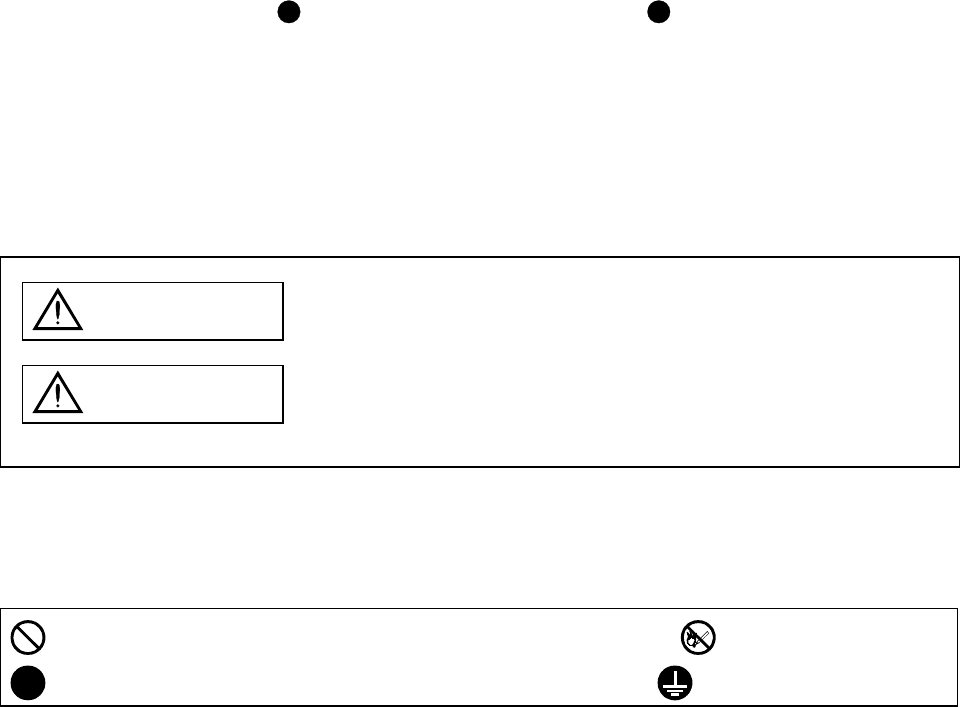
Safety Instructions
(Always read these instructions before using the equipment.)
Do not attempt to install, operate, maintain or inspect the servo amplifier and servo motor until you have read
through this Instruction Manual, Installation guide, Servo motor Instruction Manual and appended documents
carefully and can use the equipment correctly. Do not use the servo amplifier and servo motor until you have a
full knowledge of the equipment, safety information and instructions.
In this Instruction Manual, the safety instruction levels are classified into "WARNING" and "CAUTION".
WARNING Indicates that incorrect handling may cause hazardous conditions,
resulting in death or severe injury.
CAUTION Indicates that incorrect handling may cause hazardous conditions,
resulting in medium or slight injury to personnel or may cause physical
damage.
Note that the CAUTION level may lead to a serious consequence according to conditions. Please follow the
instructions of both levels because they are important to personnel safety.
What must not be done and what must be done are indicated by the following diagrammatic symbols:
: Indicates what must not be done. For example, "No Fire" is indicated by .
: Indicates what must be done. For example, grounding is indicated by .
In this Instruction Manual, instructions at a lower level than the above, instructions for other functions, and so
on are classified into "POINT".
After reading this installation guide, always keep it accessible to the operator.
A - 2
1. To prevent electric shock, note the following:
WARNING
Before wiring or inspection, switch power off and wait for more than 15 minutes. Then, confirm the voltage
is safe with voltage tester. Otherwise, you may get an electric shock.
Connect the servo amplifier and servo motor to ground.
Any person who is involved in wiring and inspection should be fully competent to do the work.
Do not attempt to wire the servo amplifier and servo motor until they have been installed. Otherwise, you
may get an electric shock.
Operate the switches with dry hand to prevent an electric shock.
The cables should not be damaged, stressed, loaded, or pinched. Otherwise, you may get an electric shock.
During power-on or operation, do not open the front cover of the servo amplifier. You may get an electric
shock.
Do not operate the servo amplifier with the front cover removed. High-voltage terminals and charging area
are exposed and you may get an electric shock.
Except for wiring or periodic inspection, do not remove the front cover even of the servo amplifier if the
power is off. The servo amplifier is charged and you may get an electric shock.
2. To prevent fire, note the following:
CAUTION
Do not install the servo amplifier, servo motor and regenerative brake resistor on or near combustibles.
Otherwise a fire may cause.
When the servo amplifier has become faulty, switch off the main servo amplifier power side. Continuous
flow of a large current may cause a fire.
When a regenerative brake resistor is used, use an alarm signal to switch main power off. Otherwise, a
regenerative brake transistor fault or the like may overheat the regenerative brake resistor, causing a fire.
3. To prevent injury, note the follow
CAUTION
Only the voltage specified in the Instruction Manual should be applied to each terminal, Otherwise, a
burst, damage, etc. may occur.
Connect the terminals correctly to prevent a burst, damage, etc.
Ensure that polarity ( , ) is correct. Otherwise, a burst, damage, etc. may occur.
Take safety measures, e.g. provide covers, to prevent accidental contact of hands and parts (cables, etc.)
with the servo amplifier heat sink, regenerative brake resistor, servo motor, etc.since they may be hot
while power is on or for some time after power-off. Their temperatures may be high and you may get burnt
or a parts may damaged.
During operation, never touch the rotating parts of the servo motor. Doing so can cause injury.
A - 3
4. Additional instructions
The following instructions should also be fully noted. Incorrect handling may cause a fault, injury, electric
shock, etc.
(1) Transportation and installation
CAUTION
Transport the products correctly according to their masses.
Stacking in excess of the specified number of products is not allowed.
Do not carry the servo motor by the cables, shaft or encoder.
Do not hold the front cover to transport the servo amplifier. The servo amplifier may drop.
Install the servo amplifier in a load-bearing place in accordance with the Instruction Manual.
Do not climb or stand on servo equipment. Do not put heavy objects on equipment.
The controller and servo motor must be installed in the specified direction.
Leave specified clearances between the servo amplifier and control enclosure walls or other equipment.
Do not install or operate the servo amplifier and servo motor which has been damaged or has any parts
missing.
Provide adequate protection to prevent screws and other conductive matter, oil and other combustible
matter from entering the servo amplifier and servo motor.
Do not drop or strike servo amplifier or servo motor. Isolate from all impact loads.
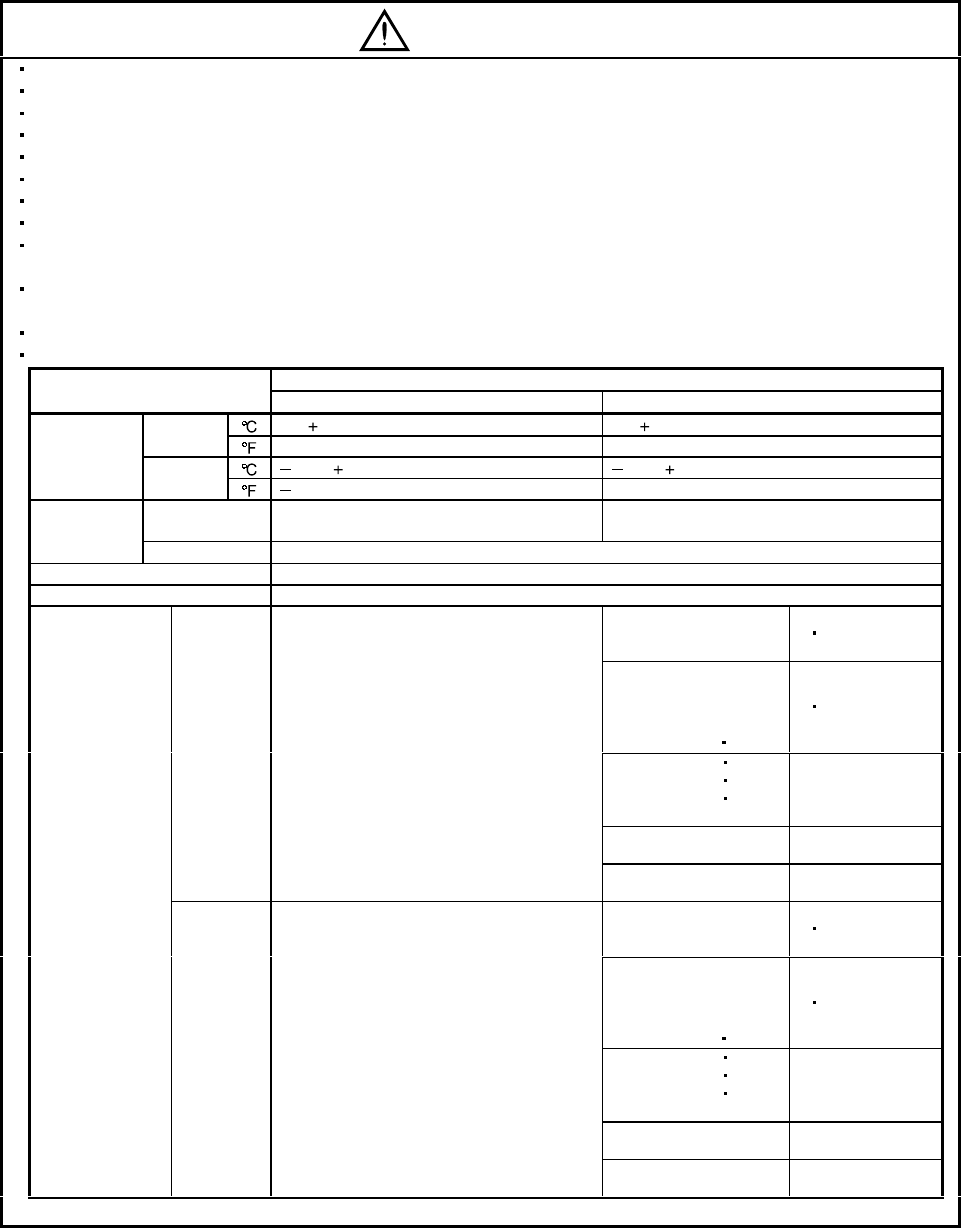
When you keep or use it, please fulfill the following environmental conditions.
Conditions
Environment Servo amplifier Servo motor
[]0 to 55 (non-freezing) 0 to 40 (non-freezing)
During
operation [] 32 to 131 (non-freezing) 32 to 104 (non-freezing)
[ ] 20 to 65 (non-freezing) 15 to 70 (non-freezing)
Ambient
temperature In storage []4 to 149 (non-freezing) 5 to 158 (non-freezing)
During
operation 90%RH or less (non-condensing) 80%RH or less (non-condensing)
Ambient
humidity In storage 90%RH or less (non-condensing)
Ambience Indoors (no direct sunlight) Free from corrosive gas, flammable gas, oil mist, dust and dirt
Altitude Max. 1000m (3280 ft) above sea level HC-KFS Series
HC-MFS Series
HC-UFS13 to 73 XY : 49
HC-SFS81
HC-SFS52 to 152
HC-SFS53 to 153
HC-RFS Series
HC-UFS 72 152
XY : 24.5
HC-SFS121 201
HC-SFS202 352
HC-SFS203 353
HC-UFS202 to 502
X : 24.5
Y : 49
HC-SFS301
HC-SFS502 to 702 X : 24.5
Y : 29.4
[m/s2] 5.9 or less
HA-LFS11K2 to 22K2 X : 11.7
Y : 29.4
HC-KFS Series
HC-MFS Series
HC-UFS 13 to 73 XY : 161
HC-SFS81
HC-SFS52 to 152
HC-SFS53 to 153
HC-RFS Series
HC-UFS 72 152
XY : 80
HC-SFS121 201
HC-SFS202 352
HC-SFS203 353
HC-UFS202 to 502
X : 80
Y : 161
HC-SFS301
HC-SFS502 to 702 X : 80
Y : 96
(Note)
Vibration
[ft/s2] 19.4 or less
HA-LFS11K2 to 22K2 X : 38
Y : 96
Note. Except the servo motor with reduction gear.
A - 4
CAUTION
Securely attach the servo motor to the machine. If attach insecurely, the servo motor may come off during
operation.
The servo motor with reduction gear must be installed in the specified direction to prevent oil leakage.
Take safety measures, e.g. provide covers, to prevent accidental access to the rotating parts of the servo
motor during operation.
Never hit the servo motor or shaft, especially when coupling the servo motor to the machine. The encoder
may become faulty.
Do not subject the servo motor shaft to more than the permissible load. Otherwise, the shaft may break.
When the equipment has been stored for an extended period of time, consult Mitsubishi.
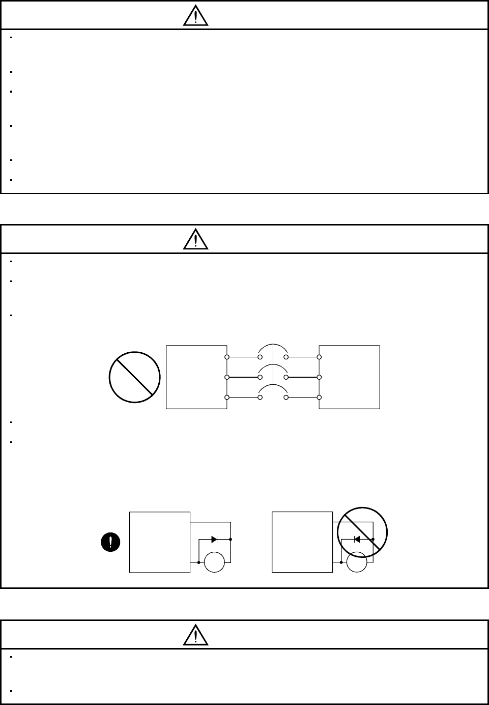
(2) Wiring
CAUTION
Wire the equipment correctly and securely. Otherwise, the servo motor may misoperate.
Do not install a power capacitor, surge absorber or radio noise filter (FR-BIF option) between the servo
motor and servo amplifier.
Connect the output terminals (U, V, W) correctly. Otherwise, the servo motor will operate improperly.
U
Servo Amplifier
V
W
U
V
W
Servo Motor
Do not connect AC power directly to the servo motor. Otherwise, a fault may occur.
The surge absorbing diode installed on the DC output signal relay of the servo amplifier must be wired in
the specified direction. Otherwise, the emergency stop (EMG) and other protective circuits may not
operate.
COM
(24VDC)
Servo
Amplifier
RA
Control
output
signal
RA
Servo
Amplifier
COM
(24VDC)
Control
output
signal
(3) Test run adjustment
CAUTION
Before operation, check the parameter settings. Improper settings may cause some machines to perform
unexpected operation.
The parameter settings must not be changed excessively. Operation will be insatiable.
A - 5
(4) Usage
CAUTION
Provide an external emergency stop circuit to ensure that operation can be stopped and power switched
off immediately.
Any person who is involved in disassembly and repair should be fully competent to do the work.
Before resetting an alarm, make sure that the run signal of the servo amplifier is off to prevent an
accident. A sudden restart is made if an alarm is reset with the run signal on.
Do not modify the equipment.
Use a noise filter, etc. to minimize the influence of electromagnetic interference, which may be caused by
electronic equipment used near the servo amplifier.
Use the servo amplifier with the specified servo motor.
Burning or breaking a servo amplifier may cause a toxic gas. Do not burn or break a servo amplifier.
The electromagnetic brake on the servo motor is designed to hold the motor shaft and should not be used
for ordinary braking.
For such reasons as service life and mechanical structure (e.g. where a ballscrew and the servo motor
are coupled via a timing belt), the electromagnetic brake may not hold the motor shaft. To ensure safety,
install a stopper on the machine side.
(5) Corrective actions
CAUTION
When it is assumed that a hazardous condition may take place at the occur due to a power failure or a
product fault, use a servo motor with electromagnetic brake or an external brake mechanism for the
purpose of prevention.
Configure the electromagnetic brake circuit so that it is activated not only by the servo amplifier signals
but also by an external emergency stop (EMG).
EMGRA
24VDC
Contacts must be open when
servo-off, when an trouble (ALM)
and when an electromagnetic brake
interlock (MBR).
Electromagnetic brake
Servo motor
Circuit must be
opened during
emergency stop (EMG).
When any alarm has occurred, eliminate its cause, ensure safety, and deactivate the alarm before
restarting operation.
When power is restored after an instantaneous power failure, keep away from the machine because the
machine may be restarted suddenly (design the machine so that it is secured against hazard if restarted).
A - 6
(6) Maintenance, inspection and parts replacement
CAUTION
With age, the electrolytic capacitor of the servo amplifier will deteriorate. To prevent a secondary accident
due to a fault, it is recommended to replace the electrolytic capacitor every 10 years when used in general
environment.
Please consult our sales representative.
(7) General instruction
To illustrate details, the equipment in the diagrams of this Specifications and Instruction Manual may have
been drawn without covers and safety guards. When the equipment is operated, the covers and safety
guards must be installed as specified. Operation must be performed in accordance with this Specifications
and Instruction Manual.
About processing of waste
When you discard servo amplifier, a battery (primary battery), and other option articles, please follow the law of
each country (area).
FOR MAXIMUM SAFETY
These products have been manufactured as a general-purpose part for general industries, and have not
been designed or manufactured to be incorporated in a device or system used in purposes related to
human life.
Before using the products for special purposes such as nuclear power, electric power, aerospace,
medicine, passenger movement vehicles or under water relays, contact Mitsubishi.
These products have been manufactured under strict quality control. However, when installing the product
where major accidents or losses could occur if the product fails, install appropriate backup or failsafe
functions in the system.
EEP-ROM life
The number of write times to the EEP-ROM, which stores parameter settings, etc., is limited to 100,000. If
the total number of the following operations exceeds 100,000, the servo amplifier and/or converter unit may
fail when the EEP-ROM reaches the end of its useful life.
Write to the EEP-ROM due to parameter setting changes
Home position setting in the absolute position detection system
Write to the EEP-ROM due to device changes
Precautions for Choosing the Products
Mitsubishi will not be held liable for damage caused by factors found not to be the cause of Mitsubishi;
machine damage or lost profits caused by faults in the Mitsubishi products; damage, secondary damage,
accident compensation caused by special factors unpredictable by Mitsubishi; damages to products other
than Mitsubishi products; and to other duties.
A - 7
COMPLIANCE WITH EC DIRECTIVES
1. WHAT ARE EC DIRECTIVES?
The EC directives were issued to standardize the regulations of the EU countries and ensure smooth
distribution of safety-guaranteed products. In the EU countries, the machinery directive (effective in
January, 1995), EMC directive (effective in January, 1996) and low voltage directive (effective in January,
1997) of the EC directives require that products to be sold should meet their fundamental safety
requirements and carry the CE marks (CE marking). CE marking applies to machines and equipment
into which servo amplifiers have been installed.
(1) EMC directive
The EMC directive applies not to the servo units alone but to servo-incorporated machines and
equipment. This requires the EMC filters to be used with the servo-incorporated machines and
equipment to comply with the EMC directive. For specific EMC directive conforming methods, refer to
the EMC Installation Guidelines (IB(NA)67310).
(2) Low voltage directive
The low voltage directive applies also to servo units alone. Hence, they are designed to comply with
the low voltage directive.
This servo is certified by TUV, third-party assessment organization, to comply with the low voltage
directive.
(3) Machine directive
Not being machines, the servo amplifiers need not comply with this directive.
2. PRECAUTIONS FOR COMPLIANCE
(1) Servo amplifiers and servo motors used
Use the servo amplifiers and servo motors which comply with the standard model.
Servo amplifier :MR-J2S-10A to MR-J2S-22KA
MR-J2S-10A1 to MR-J2S-40A1
Servo motor :HC-KFS
HC-MFS
HC-SFS
HC-RFS
HC-UFS
HA-LFS
HC-LFS
(2) Configuration
Reinforced
insulating
transformer
NFB MC M
No-fuse
breaker Magnetic
contactor
Reinforced
insulating type
24VDC
power
supply
Servo
amplifier
Servo
motor
Control box
(Note)
Note. The insulating transformer is not required for the 11kW or more servo amplifier.
(3) Environment
Operate the servo amplifier at or above the contamination level 2 set forth in IEC60664-1. For this
purpose, install the servo amplifier in a control box which is protected against water, oil, carbon, dust,
dirt, etc. (IP54).
A - 8
(4) Power supply
(a) Operate the servo amplifier 7kW or less to meet the requirements of the overvoltage category II set
forth in IEC60664-1. For this purpose, a reinforced insulating transformer conforming to the IEC
or EN standard should be used in the power input section.
Since the 11kW or more servo amplifier can be used under the conditions of the overvoltage
category III set forth in IE60664-1, a reinforced insulating transformer is not required in the power
input section.
(b) When supplying interface power from external, use a 24VDC power supply which has been
insulation-reinforced in I/O.
(5) Grounding
(a) To prevent an electric shock, always connect the protective earth (PE) terminals (marked ) of the
servo amplifier to the protective earth (PE) of the control box.
(b) Do not connect two ground cables to the same protective earth (PE) terminal. Always connect the
cables to the terminals one-to-one.
PE terminals PE terminals
(c) If a leakage current breaker is used to prevent an electric shock, the protective earth (PE) terminals
of the servo amplifier must be connected to the corresponding earth terminals.
(6) Wiring
(a) The cables to be connected to the terminal block of the servo amplifier must have crimping
terminals provided with insulating tubes to prevent contact with adjacent terminals.
Crimping terminal
Insulating tube
Cable
(b) Use the servo motor side power connector which complies with the EN Standard. The EN Standard
compliant power connector sets are available from us as options.
A - 9
(7) Auxiliary equipment and options
(a) The no-fuse breaker and magnetic contactor used should be the EN or IEC standard-compliant
products of the models described in Section 13.2.2.
(b) The sizes of the cables described in Section 13.2.1 meet the following requirements. To meet the
other requirements, follow Table 5 and Appendix C in EN60204-1.
Ambient temperature: 40 (104) [ ( )]
Sheath: PVC (polyvinyl chloride)
Installed on wall surface or open table tray
(c) Use the EMC filter for noise reduction.
(8) Performing EMC tests
When EMC tests are run on a machine/device into which the servo amplifier has been installed, it
must conform to the electromagnetic compatibility (immunity/emission) standards after it has
satisfied the operating environment/electrical equipment specifications.
For the other EMC directive guidelines on the servo amplifier, refer to the EMC Installation
Guidelines(IB(NA)67310).

A - 10
CONFORMANCE WITH UL/C-UL STANDARD
(1) Servo amplifiers and servo motors used
Use the servo amplifiers and servo motors which comply with the standard model.
Servo amplifier :MR-J2S-10A to MR-J2S-22KA
MR-J2S-10A1 to MR-J2S-40A1
Servo motor :HC-KFS
HC-MFS
HC-SFS
HC-RFS
HC-UFS
HA-LFS
HC-LFS
(2) Installation
Install a fan of 100CFM (2.8m3/min) air flow 4 in (10.16 cm) above the servo amplifier or provide
cooling of at least equivalent capability.
(3) Short circuit rating
This servo amplifier conforms to the circuit whose peak current is limited to 5000A or less. Having
been subjected to the short-circuit tests of the UL in the alternating-current circuit, the servo
amplifier conforms to the above circuit.
(4) Capacitor discharge time
The capacitor discharge time is as listed below. To ensure safety, do not touch the charging section for
15 minutes after power-off.
Servo amplifier Discharge time
[min]
MR-J2S-10A(1) 20A(1) 1
MR-J2S-40A(1) 60A 2
MR-J2S-70A to 350A 3
MR-J2S-500A 700A 5
MR-J2S-11KA 4
MR-J2S-15KA 6
MR-J2S-22KA 8
(5) Options and auxiliary equipment
Use UL/C-UL standard-compliant products.
(6) Attachment of a servo motor
For the flange size of the machine side where the servo motor is installed, refer to “CONFORMANCE
WITH UL/C-UL STANDARD” in the Servo Motor Instruction Manual.
(7) About wiring protection
For installation in United States, branch circuit protection must be provided, in accordance with the
National Electrical Code and any applicable local codes.
For installation in Canada, branch circuit protection must be provided, in accordance with the Canada
Electrical Code and any applicable provincial codes.

A - 11
<<About the manuals>>
This Instruction Manual and the MELSERVO Servo Motor Instruction Manual are required if you use
the General-Purpose AC servo MR-J2S-A for the first time. Always purchase them and use the MR-
J2S-A safely.
Relevant manuals
Manual name Manual No.
MELSERVO-J2-Super Series To Use the AC Servo Safely IB(NA)0300010
MELSERVO Servo Motor Instruction Manual SH(NA)3181
EMC Installation Guidelines IB(NA)67310

A - 12
MEMO

1
CONTENTS
1. FUNCTIONS AND CONFIGURATION 1- 1 to 1-24
1.1 Introduction..............................................................................................................................................1- 1
1.2 Function block diagram ..........................................................................................................................1- 2
1.3 Servo amplifier standard specifications................................................................................................1- 5
1.4 Function list.............................................................................................................................................1- 6
1.5 Model code definition ..............................................................................................................................1- 7
1.6 Combination with servo motor...............................................................................................................1- 9
1.7 Structure..................................................................................................................................................1-10
1.7.1 Parts identification..........................................................................................................................1-10
1.7.2 Removal and reinstallation of the front cover ..............................................................................1-15
1.8 Servo system with auxiliary equipment...............................................................................................1-19
2. INSTALLATION 2- 1 to 2- 4
2.1 Environmental conditions.......................................................................................................................2- 1
2.2 Installation direction and clearances ....................................................................................................2- 2
2.3 Keep out foreign materials.....................................................................................................................2- 3
2.4 Cable stress..............................................................................................................................................2- 4
3. SIGNALS AND WIRING 3- 1 to 3- 66
3.1 Standard connection example ................................................................................................................3- 2
3.1.1 Position control mode.......................................................................................................................3- 2
3.1.2 Speed control mode...........................................................................................................................3- 6
3.1.3 Torque control mode.........................................................................................................................3- 8
3.2 Internal connection diagram of servo amplifier ..................................................................................3-10
3.3 I/O signals................................................................................................................................................3-11
3.3.1 Connectors and signal arrangements............................................................................................3-11
3.3.2 Signal explanations.........................................................................................................................3-15
3.4 Detailed description of the signals........................................................................................................3-24
3.4.1 Position control mode......................................................................................................................3-24
3.4.2 Speed control mode..........................................................................................................................3-29
3.4.3 Torque control mode........................................................................................................................3-31
3.4.4 Position/speed control change mode ..............................................................................................3-34
3.4.5 Speed/torque control change mode.................................................................................................3-36
3.4.6 Torque/position control change mode ............................................................................................3-38
3.5 Alarm occurrence timing chart .............................................................................................................3-39
3.6 Interfaces.................................................................................................................................................3-40
3.6.1 Common line ....................................................................................................................................3-40
3.6.2 Detailed description of the interfaces............................................................................................3-41
3.7 Input power supply circuit.....................................................................................................................3-46
3.7.1 Connection example.........................................................................................................................3-46
3.7.2 Terminals..........................................................................................................................................3-48
3.7.3 Power-on sequence...........................................................................................................................3-49
3.8 Connection of servo amplifier and servo motor...................................................................................3-50
3.8.1 Connection instructions ..................................................................................................................3-50

2
3.8.2 Connection diagram.........................................................................................................................3-50
3.8.3 I/O terminals....................................................................................................................................3-52
3.9 Servo motor with electromagnetic brake .............................................................................................3-54
3.10 Grounding .............................................................................................................................................3-57
3.11 Servo amplifier terminal block (TE2) wiring method.......................................................................3-58
3.11.1 For the servo amplifier produced later than Jan. 2006.............................................................3-58
3.11.2 For the servo amplifier produced earlier than Dec. 2005..........................................................3-60
3.12 Instructions for the 3M connector.......................................................................................................3-61
3.13 Power line circuit of the MR-J2S-11KA to MR-J2S-22KA...............................................................3-62
3.13.1 Connection example ......................................................................................................................3-62
3.13.2 Servo amplifier terminals.............................................................................................................3-63
3.13.3 Servo motor terminals...................................................................................................................3-64
4. OPERATION 4- 1 to 4- 6
4.1 When switching power on for the first time..........................................................................................4- 1
4.2 Startup......................................................................................................................................................4- 2
4.2.1 Selection of control mode..................................................................................................................4- 2
4.2.2 Position control mode.......................................................................................................................4- 2
4.2.3 Speed control mode...........................................................................................................................4- 4
4.2.4 Torque control mode.........................................................................................................................4- 5
4.3 Multidrop communication ......................................................................................................................4- 6
5. PARAMETERS 5- 1 to 5- 34
5.1 Parameter list..........................................................................................................................................5- 1
5.1.1 Parameter write inhibit...................................................................................................................5- 1
5.1.2 Lists....................................................................................................................................................5- 2
5.2 Detailed description ...............................................................................................................................5-26
5.2.1 Electronic gear .................................................................................................................................5-26
5.2.2 Analog monitor.................................................................................................................................5-30
5.2.3 Using forward/reverse rotation stroke end to change the stopping pattern..............................5-33
5.2.4 Alarm history clear..........................................................................................................................5-33
5.2.5 Position smoothing ..........................................................................................................................5-34
6. DISPLAY AND OPERATION 6- 1 to 6-16
6.1 Display flowchart.....................................................................................................................................6- 1
6.2 Status display ..........................................................................................................................................6- 2
6.2.1 Display examples..............................................................................................................................6- 2
6.2.2 Status display list.............................................................................................................................6- 3
6.2.3 Changing the status display screen................................................................................................6- 4
6.3 Diagnostic mode.......................................................................................................................................6- 5
6.4 Alarm mode..............................................................................................................................................6- 7
6.5 Parameter mode ......................................................................................................................................6- 8
6.6 External I/O signal display.....................................................................................................................6- 9
6.7 Output signal (DO) forced output.........................................................................................................6-12
6.8 Test operation mode...............................................................................................................................6-13
6.8.1 Mode change.....................................................................................................................................6-13
6.8.2 Jog operation....................................................................................................................................6-14

3
6.8.3 Positioning operation.......................................................................................................................6-15
6.8.4 Motor-less operation........................................................................................................................6-16
7. GENERAL GAIN ADJUSTMENT 7- 1 to 7-12
7.1 Different adjustment methods ...............................................................................................................7- 1
7.1.1 Adjustment on a single servo amplifier..........................................................................................7- 1
7.1.2 Adjustment using MR Configurator (servo configuration software)...........................................7- 2
7.2 Auto tuning ..............................................................................................................................................7- 3
7.2.1 Auto tuning mode .............................................................................................................................7- 3
7.2.2 Auto tuning mode operation............................................................................................................7- 4
7.2.3 Adjustment procedure by auto tuning............................................................................................7- 5
7.2.4 Response level setting in auto tuning mode...................................................................................7- 6
7.3 Manual mode 1 (simple manual adjustment).......................................................................................7- 7
7.3.1 Operation of manual mode 1 ...........................................................................................................7- 7
7.3.2 Adjustment by manual mode 1 .......................................................................................................7- 7
7.4 Interpolation mode.................................................................................................................................7-10
7.5 Differences in auto tuning between MELSERVO-J2 and MELSERVO-J2-Super..........................7-11
7.5.1 Response level setting.....................................................................................................................7-11
7.5.2 Auto tuning selection.......................................................................................................................7-11
8. SPECIAL ADJUSTMENT FUNCTIONS 8- 1 to 8-10
8.1 Function block diagram ..........................................................................................................................8- 1
8.2 Machine resonance suppression filter...................................................................................................8- 1
8.3 Adaptive vibration suppression control.................................................................................................8- 3
8.4 Low-pass filter .........................................................................................................................................8- 4
8.5 Gain changing function...........................................................................................................................8- 5
8.5.1 Applications.......................................................................................................................................8- 5
8.5.2 Function block diagram....................................................................................................................8- 5
8.5.3 Parameters........................................................................................................................................8- 6
8.5.4 Gain changing operation..................................................................................................................8- 8
9. INSPECTION 9- 1 to 9- 2
10. TROUBLESHOOTING 10- 1 to 10-14
10.1 Trouble at start-up..............................................................................................................................10- 1
10.1.1 Position control mode...................................................................................................................10- 1
10.1.2 Speed control mode.......................................................................................................................10- 4
10.1.3 Torque control mode.....................................................................................................................10- 5
10.2 When alarm or warning has occurred...............................................................................................10- 6
10.2.1 Alarms and warning list..............................................................................................................10- 6
10.2.2 Remedies for alarms.....................................................................................................................10- 7
10.2.3 Remedies for warnings................................................................................................................10-13
11. OUTLINE DIMENSION DRAWINGS 11- 1 to 11-10
11.1 Servo amplifiers...................................................................................................................................11- 1

4
11.2 Connectors............................................................................................................................................11- 8
12. CHARACTERISTICS 12- 1 to 12- 8
12.1 Overload protection characteristics...................................................................................................12- 1
12.2 Power supply equipment capacity and generated loss....................................................................12- 2
12.3 Dynamic brake characteristics...........................................................................................................12- 5
12.4 Encoder cable flexing life....................................................................................................................12- 7
12.5 Inrush currents at power-on of main circuit and control circuit ....................................................12- 8
13. OPTIONS AND AUXILIARY EQUIPMENT 13- 1 to 13-54
13.1 Options..................................................................................................................................................13- 1
13.1.1 Regenerative brake options.........................................................................................................13- 1
13.1.2 Brake unit.....................................................................................................................................13-10
13.1.3 Power regeneration converter ....................................................................................................13-12
13.1.4 External dynamic brake..............................................................................................................13-15
13.1.5 Cables and connectors.................................................................................................................13-18
13.1.6 Junction terminal block (MR-TB20)..........................................................................................13-26
13.1.7 Maintenance junction card (MR-J2CN3TM)............................................................................13-28
13.1.8 Battery (MR-BAT, A6BAT).........................................................................................................13-29
13.1.9 MR Configurator (Servo configurations software) ...................................................................13-30
13.1.10 Power regeneration common converter...................................................................................13-32
13.1.11 Heat sink outside mounting attachment (MR-JACN)...........................................................13-36
13.2 Auxiliary equipment ..........................................................................................................................13-39
13.2.1 Recommended wires....................................................................................................................13-39
13.2.2 No-fuse breakers, fuses, magnetic contactors...........................................................................13-42
13.2.3 Power factor improving reactors................................................................................................13-42
13.2.4 Power factor improving DC reactors..........................................................................................13-43
13.2.5 Relays............................................................................................................................................13-44
13.2.6 Surge absorbers ...........................................................................................................................13-44
13.2.7 Noise reduction techniques.........................................................................................................13-44
13.2.8 Leakage current breaker.............................................................................................................13-50
13.2.9 EMC filter.....................................................................................................................................13-52
13.2.10 Setting potentiometers for analog inputs................................................................................13-54
14. COMMUNICATION FUNCTIONS 14- 1 to 14- 28
14.1 Configuration.......................................................................................................................................14- 1
14.1.1 RS-422 configuration....................................................................................................................14- 1
14.1.2 RS-232C configuration.................................................................................................................14- 2
14.2 Communication specifications............................................................................................................14- 3
14.2.1 Communication overview.............................................................................................................14- 3
14.2.2 Parameter setting.........................................................................................................................14- 4
14.3 Protocol.................................................................................................................................................14- 5
14.4 Character codes ...................................................................................................................................14- 7
14.5 Error codes...........................................................................................................................................14- 8
14.6 Checksum.............................................................................................................................................14- 8
14.7 Time-out operation..............................................................................................................................14- 9
14.8 Retry operation....................................................................................................................................14- 9

5
14.9 Initialization........................................................................................................................................14-10
14.10 Communication procedure example...............................................................................................14-10
14.11 Command and data No. list.............................................................................................................14-11
14.11.1 Read commands.........................................................................................................................14-11
14.11.2 Write commands........................................................................................................................14-12
14.12 Detailed explanations of commands...............................................................................................14-14
14.12.1 Data processing..........................................................................................................................14-14
14.12.2 Status display ............................................................................................................................14-16
14.12.3 Parameter...................................................................................................................................14-17
14.12.4 External I/O pin statuses (DIO diagnosis)..............................................................................14-19
14.12.5 Disable/enable of external I/O signals (DIO)..........................................................................14-20
14.12.6 External input signal ON/OFF (test operation).....................................................................14-21
14.12.7 Test operation mode..................................................................................................................14-22
14.12.8 Output signal pin ON/OFF output signal (DO) forced output..............................................14-24
14.12.9 Alarm history.............................................................................................................................14-25
14.12.10 Current alarm..........................................................................................................................14-26
14.12.11 Other commands......................................................................................................................14-27
15. ABSOLUTE POSITION DETECTION SYSTEM 15- 1 to 15- 66
15.1 Outline..................................................................................................................................................15- 1
15.1.1 Features.........................................................................................................................................15- 1
15.1.2 Restrictions....................................................................................................................................15- 1
15.2 Specifications.......................................................................................................................................15- 2
15.3 Battery installation procedure...........................................................................................................15- 3
15.4 Standard connection diagram ............................................................................................................15- 4
15.5 Signal explanation...............................................................................................................................15- 5
15.6 Startup procedure................................................................................................................................15- 6
15.7 Absolute position data transfer protocol...........................................................................................15- 7
15.7.1 Data transfer procedure...............................................................................................................15- 7
15.7.2 Transfer method ...........................................................................................................................15- 8
15.7.3 Home position setting..................................................................................................................15-17
15.7.4 Use of servo motor with electromagnetic brake .......................................................................15-19
15.7.5 How to process the absolute position data at detection of stroke end....................................15-20
15.8 Examples of use..................................................................................................................................15-21
15.8.1 MELSEC-A1S (A1SD71).............................................................................................................15-21
15.8.2 MELSEC FX(2N)-32MT (FX(2N)-1PG).....................................................................................15-35
15.8.3 MELSEC A1SD75(AD75) ...........................................................................................................15-47
15.9 Confirmation of absolute position detection data............................................................................15-62
15.10 Absolute position data transfer errors ...........................................................................................15-63
15.10.1 Corrective actions......................................................................................................................15-63
15.10.2 Error resetting conditions.........................................................................................................15-65
Appendix App- 1 to App- 4
App 1. Signal arrangement recording sheets.........................................................................................App- 1
App 2. Status display block diagram......................................................................................................App- 2
App 3. Combination of servo amplifier and servo motor ......................................................................App- 3

6
Optional Servo Motor Instruction Manual CONTENTS
The rough table of contents of the optional MELSERVO Servo Motor Instruction Manual is introduced
here for your reference. Note that the contents of the Servo Motor Instruction Manual are not included
in the Servo Amplifier Instruction Manual.
1. INTRODUCTION
2. INSTALLATION
3. CONNECTORS USED FOR SERVO MOTOR WIRING
4. INSPECTION
5. SPECIFICATIONS
6. CHARACTERISTICS
7. OUTLINE DIMENSION DRAWINGS
8. CALCULATION METHODS FOR DESIGNING

1 - 1
1. FUNCTIONS AND CONFIGURATION
1. FUNCTIONS AND CONFIGURATION
1.1 Introduction
The Mitsubishi MELSERVO-J2-Super series general-purpose AC servo is based on the MELSERVO-J2
series and has further higher performance and higher functions.
It has position control, speed control and torque control modes. Further, it can perform operation with the
control modes changed, e.g. position/speed control, speed/torque control and torque/position control.
Hence, it is applicable to a wide range of fields, not only precision positioning and smooth speed control of
machine tools and general industrial machines but also line control and tension control.
As this new series has the RS-232C or RS-422 serial communication function, a MR Configurator (servo
configuration software)-installed personal computer or the like can be used to perform parameter setting,
test operation, status display monitoring, gain adjustment, etc.
With real-time auto tuning, you can automatically adjust the servo gains according to the machine.
The MELSERVO-J2-Super series servo motor is equipped with an absolute position encoder which has
the resolution of 131072 pulses/rev to ensure more accurate control as compared to the MELSERVO-J2
series. Simply adding a battery to the servo amplifier makes up an absolute position detection system.
This makes home position return unnecessary at power-on or alarm occurrence by setting a home position
once.
(1) Position control mode
An up to 500kpps high-speed pulse train is used to control the speed and direction of a motor and
execute precision positioning of 131072 pulses/rev resolution.
The position smoothing function provides a choice of two different modes appropriate for a machine, so
a smoother start/stop can be made in response to a sudden position command.
A torque limit is imposed on the servo amplifier by the clamp circuit to protect the power transistor in
the main circuit from overcurrent due to sudden acceleration/deceleration or overload. This torque
limit value can be changed to any value with an external analog input or the parameter.
(2) Speed control mode
An external analog speed command (0 to 10VDC) or parameter-driven internal speed command
(max. 7 speeds) is used to control the speed and direction of a servo motor smoothly.
There are also the acceleration/deceleration time constant setting in response to speed command, the
servo lock function at a stop time, and automatic offset adjustment function in response to external
analog speed command.
(3) Torque control mode
An external analog torque command (0 to 8VDC) or parameter-driven internal torque command is
used to control the torque output by the servo motor.
To protect misoperation under no load, the speed limit function (external or internal setting) is also
available for application to tension control, etc.
1 - 2
1. FUNCTIONS AND CONFIGURATION
1.2 Function block diagram
The function block diagram of this servo is shown below.
(1) MR-J2S-350A or less
Regenerative
brake Base amplifier Voltage
detection
Overcurrent
protection
Encoder
Dynamic
brake
Current
detector
CHARGE
lamp
RADS
Control
circuit
power
supply
(MR-J2S-200A or more)
Fan
Electro-
magnetic
brake
Servo motor
D
C
P
Regenerative brake option
NFB
Power
supply
3-phase
200 to
230VAC,
1-phase
230VAC or
1-phase
100to120VAC
MC L1
L2
L3
L11
L21
A/D
CN1A CN1B
D I/O control
Servo on
Start
Failure, etc.
RS-232C
CN3
RS-422 D/A
Analog
(2 channels) RS-422/RS-232C
Controller
B2
I/F
Servo amplifier
Analog monitor
(2 channels)
Model position
control
Model speed
control
Pulse
input
Model
position
Actual position
control
Actual speed
control
Current
control
Model
torque
Virtual
motor
Virtual
encoder
CN2
MR-BAT
Optional battery
(for absolute position
detection system)
U
V
W
U
V
W
M
B1
Current
detection
Model
speed
(Note2) (Note1)
Note 1. The built-in regenerative brake resistor is not provided for the MR-J2S-10A(1).
2. For 1-phase 230VAC, connect the power supply to L1,L2 and leave L3 open.
L3 is not provided for a 1-phase 100 to120VAC power supply.
CON1
Regene-
rative
TR
1 - 3
1. FUNCTIONS AND CONFIGURATION
(2) MR-J2S-500A MR-J2S-700A
Regenerative
brake Base amplifier Voltage
detection
Overcurrent
protection
Encoder
Dynamic
brake
Current
detector
CHARGE
lamp
RADS
Control
circuit
power
supply
Fan
Electro-
magnetic
brake
Servo motor
NCP
Regenerative brake option
NFB
Power
supply
3-phase
200 to
230VAC
MC L1
L2
L3
L11
L21
A/D
CN1A CN1B
D I/O control
Servo on
Start
Failure, etc.
RS-232C
CN3
RS-422 D/A
Analog
(2 channels) RS-422/RS-232C
Controller
B2
I/F
Servo amplifier
Analog monitor
(2 channels)
Model position
control
Model speed
control
Pulse
input
Model
position
Actual position
control
Actual speed
control
Current
control
Model
torque
Virtual
motor
Virtual
encoder
CN2
MR-BAT
Optional battery
(for absolute position
detection system)
U
V
W
U
V
W
SM
B1
Current
detection
Model
speed
CON1
Regene-
rative
TR
1 - 4
1. FUNCTIONS AND CONFIGURATION
(3) MR-J2S-11KA or more
CN2
DS
CON1
L1
L2
L3
L11
L21
NFB MC
MR-BAT
PC
U
V
W
U
V
W
SM
B1
B2
NP1
A/D RS-232C
RS-422 D/A
RS-422/RS-232C
I/F
CN3 CN4
Power
supply
3-phase
200 to
230VAC,
1-phase
230VAC
Servo amplifier
Regenerative brake option
CHARGE
lamp Regene-
rative
TR
Current
detector
Servo motor
Electro-
magnetic
brake
Encoder
Current
detection
Overcurrent
protection
Voltage
detection
Base
amplifier
Regenerative
brake
Control
power
supply
Fan
Model position
control
Model speed
control
Virtual
encoder
Virtual
motor
Model
torque
Model
speed
Model
position
Actual position
control
Actual speed
control
Current
control
Analog
(2 channels)
D I/O control
Servo on
Start
Failure, etc.
Analog monitor
(2 channels)
Controller
Optional battery
(for absolute position
detection system)
Position
command
input
CN1A CN1B
1 - 5
1. FUNCTIONS AND CONFIGURATION
1.3 Servo amplifier standard specifications
Servo Amplifier
MR-J2S-
Item
10A 20A 40A 60A 70A 100A 200A 350A 500A 700A 11KA 15KA 22KA 10A1 20A1 40A1
Voltage/frequency 3-phase 200 to 230VAC,
50/60Hz or 1-phase
230VAC, 50/60Hz 3-phase 200 to 230VAC, 50/60Hz 1-phase 100 to
120VAC
50/60Hz
Permissible voltage fluctuation
3-phase 200 to 230VAC:
170 to 253VAC
1-phase 230VAC: 207 to
253VAC
3-phase 170 to 253VAC 1-phase
85 to 127VAC
Permissible frequency fluctuation Within 5%
Power supply capacity Refer to Section12.2
Power supply
Inrush current Refer to Section 12.5
Control system Sine-wave PWM control, current control system
Dynamic brake Built-in External option Built-in
Protective functions
Overcurrent shut-off, regenerative overvoltage shut-off, overload shut-off (electronic
thermal relay), servo motor overheat protection, encoder error protection, regenerative
brake error protection, undervoltage, instantaneous power failure protection, overspeed
protection, excessive error protection
Max. input pulse frequency 500kpps (for differential receiver), 200kpps (for open collector)
Command pulse multiplying factor Electronic gear A:1 to 65535 131072 B:1 to 65535, 1/50 A/B 500
In-position range setting 0 to 10000 pulse (command pulse unit)
Error excessive (Note) 2.5 revolutions
Position control mode
Torque limit Set by parameter setting or external analog input (0 to 10VDC/maximum torque)
Speed control range Analog speed command 1: 2000, internal speed command 1: 5000
Analog speed command input 0 to 10VDC / Rated speed
Speed fluctuation ratio 0.01% or less (load fluctuation 0 to 100%)
0% or less (power fluctuation 10%)
0.2% max.(ambient temperature 25 10 ) for external speed setting only
Speed control mode
Torque limit Set by parameter setting or external analog input (0 to 10VDC/maximum torque)
Analog torque command input 0 to 8VDC / Maximum torque (input impedance 10 to 12k )
Torque
control
mode Speed limit Set by parameter setting or external analog input (0 to 10VDC/Rated speed)
Structure Self-cooled, open (IP00) Force-cooling, open (IP00) Self-cooled,
open(IP00)
[]0 to 55 (non-freezing)
Operation [] 32 to 131 (non-freezing)
[ ] 20 to 65 (non-freezing)
Ambient
temperature Storage []4 to 149 (non-freezing)
Operation
Ambient
humidity Storage 90%RH or less (non-condensing)
Ambient Indoors (no direct sunlight)
Free from corrosive gas, flammable gas, oil mist, dust and dirt
Altitude Max. 1000m (3280ft) above sea level
5.9 [m/s2] or less
Environment
Vibration 19.4 [ft/s2] or less
[kg] 0.7 0.7 1.1 1.1 1.7 1.7 2.0 2.0 4.9 15 16 16 20 0.7 0.7 1.1
Mass [lb] 1.5 1.5 2.4 2.4 3.75 3.75 4.4 4.4 10.8 33.1 35.3 35.3 44.1 1.5 1.5 2.4
Note. The error excessive detection for 2.5 revolutions is available only when the servo amplifier of software version B0 or later is
used. When the software version is earlier than B0, the error excessive detection level of that servo amplifier is 10 revolutions.

1 - 6
1. FUNCTIONS AND CONFIGURATION
1.4 Function list
The following table lists the functions of this servo. For details of the functions, refer to the reference field.
Function Description (Note)
Control mode Reference
Position control mode This servo is used as position control servo. P Section 3.1.1
Section 3.4.1
Section 4.2.2
Speed control mode This servo is used as speed control servo. S Section 3.1.2
Section 3.4.2
Section 4.2.3
Torque control mode This servo is used as torque control servo. T Section 3.1.3
Section 3.4.3
Section 4.2.4
Position/speed control change
mode Using external input signal, control can be switched
between position control and speed control. P/S Section 3.4.4
Speed/torque control change
mode Using external input signal, control can be switched
between speed control and torque control. S/T Section 3.4.5
Torque/position control
change mode Using external input signal, control can be switched
between torque control and position control. T/P Section 3.4.6
High-resolution encoder High-resolution encoder of 131072 pulses/rev is used as a
servo motor encoder. P, S, T
Absolute position detection
system Merely setting a home position once makes home position
return unnecessary at every power-on. PChapter 15
Gain changing function You can switch between gains during rotation and gains
during stop or use an external signal to change gains
during operation. P, S Section 8.5
Adaptive vibration
suppression control
Servo amplifier detects mechanical resonance and sets filter
characteristics automatically to suppress mechanical
vibration. P, S, T Section 8.3
Low-pass filter Suppresses high-frequency resonance which occurs as servo
system response is increased. P, S, T Section 8.4
Machine analyzer function
Analyzes the frequency characteristic of the mechanical
system by simply connecting a MR Configurator (servo
configuration) software-installed personal computer and
servo amplifier.
P
Machine simulation Can simulate machine motions on a personal computer
screen on the basis of the machine analyzer results. P
Gain search function Personal computer changes gains automatically and
searches for overshoot-free gains in a short time. P
Slight vibration suppression
control Suppresses vibration of 1 pulse produced at a servo motor
stop. P Section 7.5
Electronic gear Input pulses can be multiplied by 1/50 to 50. P Parameters No. 3, 4
Auto tuning Automatically adjusts the gain to optimum value if load
applied to the servo motor shaft varies. Higher in
performance than MR-J2 series servo amplifier. P, S Chapter 7
Position smoothing Speed can be increased smoothly in response to input pulse. P Parameter No. 7
S-pattern acceleration/
deceleration time constant Speed can be increased and decreased smoothly. S, T Parameter No. 13
Regenerative brake option Used when the built-in regenerative brake resistor of the
servo amplifier does not have sufficient regenerative
capability for the regenerative power generated. P, S, T Section 13.1.1
Brake unit Used when the regenerative brake option cannot provide
enough regenerative power.
Can be used with the MR-J2S-500A to MR-J2S-22KA. P, S, T Section 13.1.2

1 - 7
1. FUNCTIONS AND CONFIGURATION
Function Description (Note)
Control mode Reference
Return converter Used when the regenerative brake option cannot provide
enough regenerative power.
Can be used with the MR-J2S-500A to MR-J2S-22KA. P, S, T Section 13.1.3
Alarm history clear Alarm history is cleared. P, S, T Parameter No. 16
Restart after instantaneous
power failure
If the input power supply voltage had reduced to cause an
alarm but has returned to normal, the servo motor can be
restarted by merely switching on the start signal. S Parameter No. 20
Command pulse selection Command pulse train form can be selected from among four
different types. P Parameter No. 21
Input signal selection Forward rotation start, reverse rotation start, servo-on
(SON) and other input signals can be assigned to any pins. P, S, T Parameters
No. 43 to 48
Torque limit Servo motor torque can be limited to any value. P, S Section 3.4.1 (5)
Parameter No. 28
Speed limit Servo motor speed can be limited to any value. T Section 3.4.3 (3)
Parameter No. 8
to 10,72 to 75
Status display Servo status is shown on the 5-digit, 7-segment LED
display P, S, T Section 6.2
External I/O signal display ON/OFF statuses of external I/O signals are shown on the
display. P, S, T Section 6.6
Output signal (DO)
forced output
Output signal can be forced on/off independently of the
servo status.
Use this function for output signal wiring check, etc. P, S, T Section 6.7
Automatic VC offset Voltage is automatically offset to stop the servo motor if it
does not come to a stop at the analog speed command (VC)
or analog speed limit (VLA) of 0V. S, T Section 6.3
Test operation mode JOG operation positioning operation motor-less operation
DO forced output. P, S, T Section 6.8
Analog monitor output Servo status is output in terms of voltage in real time. P, S, T Parameter No. 17
MR Configurator
(Servo configuration software) Using a personal computer, parameter setting, test
operation, status display, etc. can be performed. P, S, T Section 13.1.9
Alarm code output If an alarm has occurred, the corresponding alarm number
is output in 3-bit code. P, S, T Section 10.2.1
Note. P: Position control mode, S: Speed control mode, T: Torque control mode
P/S: Position/speed control change mode, S/T: Speed/torque control change mode, T/P: Torque/position control change mode
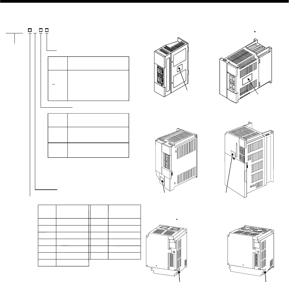
1.5 Model code definition
(1) Rating plate
POWER
MITSUBISHI AC SERVO
MADE IN JAPAN
MODEL MR-J2S-60A
MITSUBISHI ELECTRIC CORPORATION
600W
3.2A 3PH 1PH200-230V 50Hz
170V 0-360Hz 3.6A
POWER :
INPUT :
OUTPUT :
SERIAL :
AC SERVO
A5
PASSED
Model
Capacity
Applicable power supply
Rated output current
Serial number
3PH 1PH200-230V 60Hz
5.5A 1PH 230V 50/60Hz
TC3 AAAAG52
1 - 8
1. FUNCTIONS AND CONFIGURATION
(2) Model
MR–J2S–100A or less MR–J2S–200A 350A
General-purpose interface
Rated output
Rating plate Rating plate
MR–J2S–
Series
A
Power Supply
Power supply
None 3-phase 200 to 230VAC
(Note1) 1-phase 230VAC
(Note2)
11-phase 100V to 120VAC
Symbol MR-J2S-500A MR-J2S-700A
Rating plate Rating plate
Rated
output [kW]
0.110
Symbol
0.220 0.440 0.660 0.75
70 1100 2200
3.5350
Rated
output [kW]
Symbol
5500 7700
11k
15k
22k
11
15
22
MR-J2S-11KA 15KA MR-J2S-22KA
Rating plateRating plate
Description
PX
Indicates a servo amplifier
of 11 to 22kw that does not
use a regenerative resistor
as standard accessory.
Symbol
With no regenerative resistor
Note 1. 1-phase 230V is supported
by 750W or less.
2. 1-phase 100V to 120V is
supported by 400W or less.
1 - 9
1. FUNCTIONS AND CONFIGURATION
1.6 Combination with servo motor
The following table lists combinations of servo amplifiers and servo motors. The same combinations apply
to the models with electromagnetic brakes and the models with reduction gears.
Servo motors
HC-SFS HC-UFS
Servo amplifier HC-KFS HC-MFS (Note1)
1000r/min 2000r/min (Note1)
3000r/min
HC-RFS 2000r/min 3000r/min
MR-J2S-10A(1) 053 13 053 13 13
MR-J2S-20A(1) 23 23 23
MR-J2S-40A(1) 43 43 43
MR-J2S-60A 52 53
MR-J2S-70A (Note1) 73 73 72 73
MR-J2S-100A 81 102 103
MR-J2S-200A 121 201 152 202 153 203 103 153 152
MR-J2S-350A 301 352 353 (Note1)203 (Note1)202
MR-J2S-500A (Note1)502 (Note1)
353 503 (Note1)
352 502
MR-J2S-700A (Note1)702
Servo motors
HA-LFS
Servo amplifier
1000r/min 1500r/min 2000r/min
(Note1)
HC-LFS
MR-J2S-60A 52
MR-J2S-100A 102
MR-J2S-200A 152
MR-J2S-350A 202
MR-J2S-500A (Note1)502 302
MR-J2S-700A (Note2)601 (Note2)701M (Note1)702
MR-J2S-11KA 801 12K1 11K1M 11K2
MR-J2S-15KA 15K1 15K1M 15K2
MR-J2S-22KA 20K1 25K1 22K1M 22K2
Note1. These servo motors may not be connected depending on the production time of the servo amplifier. Please refer to app3.
2. Consult us since the servo amplifier to be used with any of these servo motors is optional.
1 - 10
1. FUNCTIONS AND CONFIGURATION
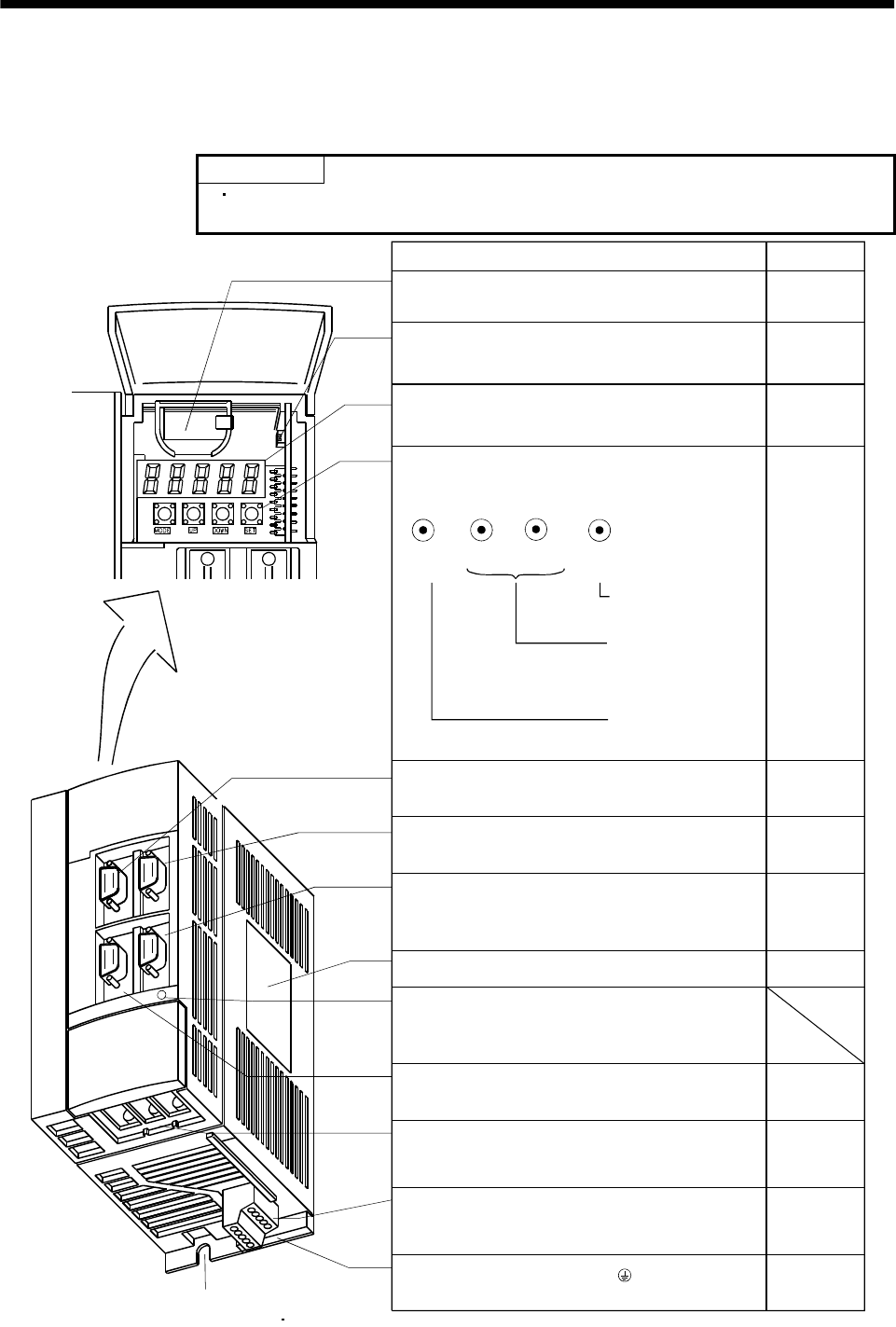
1.7 Structure
1.7.1 Parts identification
(1) MR-J2S-100A or less
POINT
The servo amplifier is shown without the front cover. For removal of the
front cover, refer to Section 1.7.2.
Used to set data.
Used to change the
display or data in each
mode.
Used to change the
mode.
Reference
Section15.3
Chapter6
Name/Application
Battery holder
Contains the battery for absolute position data backup.
Battery connector (CON1)
Used to connect the battery for absolute position data
backup.
Display
The 5-digit, seven-segment LED shows the servo
status and alarm number.
MODE UP DOWN SET
I/O signal connector (CN1A)
Used to connect digital I/O signals.
Communication connector (CN3)
Used to connect a command device (RS-422/RS-232C)
and output analog monitor data.
Name plate
Charge lamp
Lit to indicate that the main circuit is charged. While
this lamp is lit, do not reconnect the cables.
Encoder connector (CN2)
Used to connect the servo motor encoder.
Main circuit terminal block (TE1)
Used to connect the input power supply and servo
motor.
Protective earth (PE) terminal ( )
Ground terminal.
Section15.3
Operation section
Used to perform status display, diagnostic, alarm and
parameter setting operations.
Chapter6
Section3.3
I/O signal connector (CN1B)
Used to connect digital I/O signals. Section3.3
Chapter14
Section13.1.5
Section1.5
Section3.3
Section13.1.5
Control circuit terminal block (TE2)
Used to connect the control circuit power supply and
regenerative brake option.
Section3.7
Section11.1
Section3.7
Section11.1
Section13.1.1
Section3.10
Section11.1
Section3.3
Fixed part(2places)
(For MR-J2S-70A 100A 3 places)
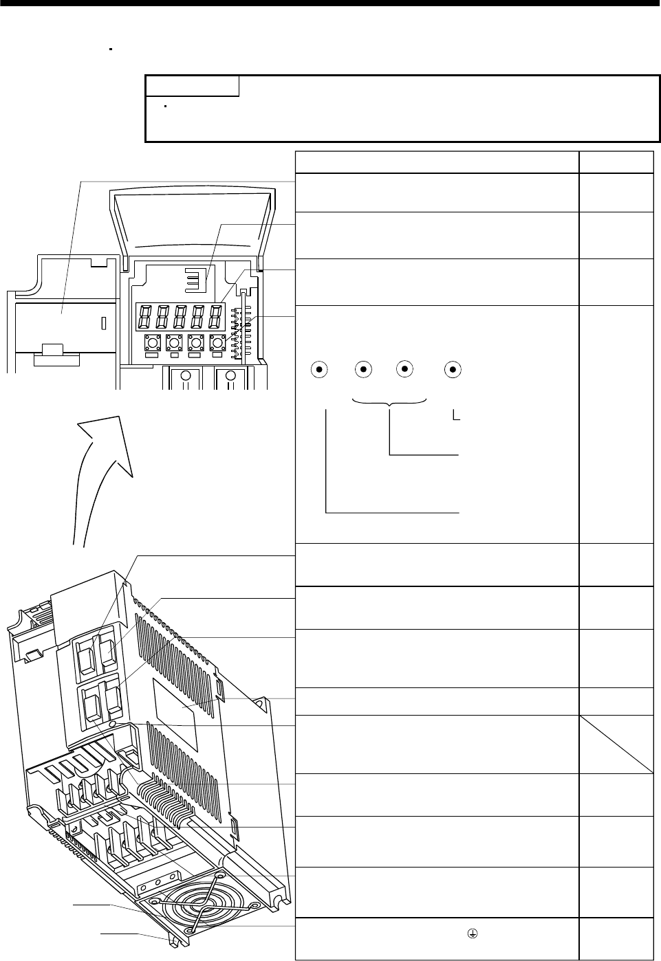
1 - 11
1. FUNCTIONS AND CONFIGURATION
(2) MR-J2S-200A MR-J2S-350A
POINT
The servo amplifier is shown without the front cover. For removal of the
front cover, refer to Section 1.7.2.
Used to set data.
Used to change the
display or data in each
mode.
Used to change the
mode.
Reference
Section15.3
Chapter6
Name/Application
Battery holder
Contains the battery for absolute position data backup.
Battery connector (CON1)
Used to connect the battery for absolute position data
backup.
Display
The 5-digit, seven-segment LED shows the servo
status and alarm number.
MODE UP DOWN SET
I/O signal connector (CN1A)
Used to connect digital I/O signals.
Communication connector (CN3)
Used to connect a command device (RS-422/RS232C)
and output analog monitor data.
Name plate
Charge lamp
Lit to indicate that the main circuit is charged. While
this lamp is lit, do not reconnect the cables.
Encoder connector (CN2)
Used to connect the servo motor encoder.
Main circuit terminal block (TE1)
Used to connect the input power supply and servo
motor.
Protective earth (PE) terminal ( )
Ground terminal.
Section15.3
Operation section
Used to perform status display, diagnostic, alarm and
parameter setting operations.
Chapter6
Section3.3
I/O signal connector (CN1B)
Used to connect digital I/O signals. Section3.3
Section3.3
Section13.1.5
Chapter14
Section1.5
Section3.3
Section13.1.5
Control circuit terminal block (TE2)
Used to connect the control circuit power supply and
regenerative brake option.
Section3.7
Section11.1
Section3.7
Section11.1
Section13.1.1
Section3.10
Section11.1
Cooling fan
Fixed part
(4 places)
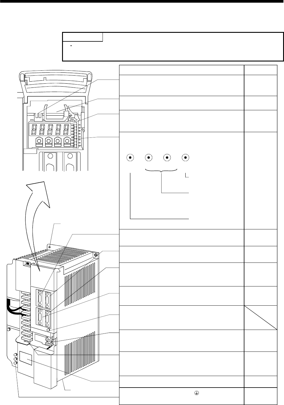
1 - 12
1. FUNCTIONS AND CONFIGURATION
(3) MR-J2S-500A
POINT
The servo amplifier is shown without the front cover. For removal of the
front cover, refer to Section 1.7.2.
MODE UP DOWN SET
MODE UP DOWN SET
Name/Application Reference
Battery connector (CON1)
Used to connect the battery for absolute position data
backup. Section15.3
Battery holder
Contains the battery for absolute position data backup. Section15.3
Display
The 5-digit, seven-segment LED shows the servo
status and alarm number. Chapter6
Operation section
Used to perform status display, diagnostic, alarm and
parameter setting operations.
Chapter6
Used to set data.
Used to change the
display or data in each
mode.
Used to change the
mode.
I/O signal connector (CN1A)
Used to connect digital I/O signals. Section3.3
Section3.3
I/O signal connector (CN1B)
Used to connect digital I/O signals.
Section3.3
Section13.1.5
Chapter14
Communication connector (CN3)
Used to connect a command device (RS-422/RS232C)
and output analog monitor data.
Encoder connector (CN2)
Used to connect the servo motor encoder. Section3.3
Section13.1.5
Charge lamp
Lit to indicate that the main circuit is charged.
While this lamp is lit, do not reconnect the cables.
Control circuit terminal block (TE2)
Used to connect the control circuit power supply and
regenerative brake option.
Section3.7
Section11.1.1
Main circuit terminal block (TE1)
Used to connect the input power supply and servo
motor.
Section3.7
Section11.1
Section13.1.1
Name plate Section1.5
Protective earth (PE) terminal ( )
Ground terminal. Section3.10
Section11.1
Fixed part
(4 places)
Cooling fan
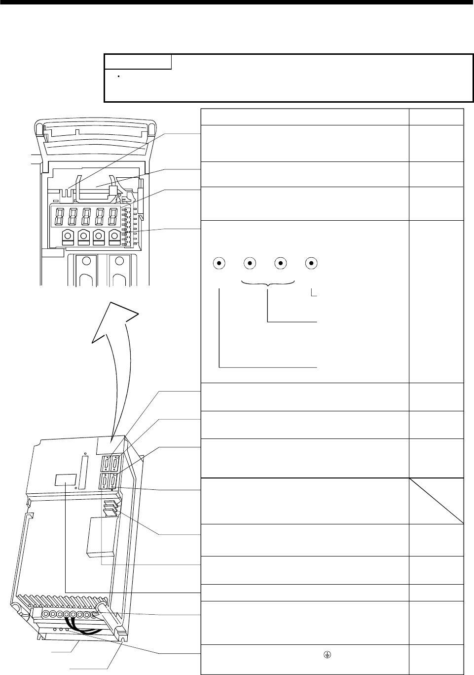
1 - 13
1. FUNCTIONS AND CONFIGURATION
(4) MR-J2S-700A
POINT
The servo amplifier is shown without the front cover. For removal of the
front cover, refer to next page.
MODE UP DOWN SET
MODE UP DOWN SET
Name/Application Reference
Battery connector (CON1)
Used to connect the battery for absolute position data
backup. Section15.3
Battery holder
Contains the battery for absolute position data backup. Section15.3
Display
The 5-digit, seven-segment LED shows the servo
status and alarm number. Chapter6
Operation section
Used to perform status display, diagnostic, alarm and
parameter setting operations.
Chapter6
Used to set data.
Used to change the
display or data in each
mode.
Used to change the
mode.
I/O signal connector (CN1A)
Used to connect digital I/O signals. Section3.3
I/O signal connector (CN1B)
Used to connect digital I/O signals. Section3.3
Communication connector (CN3)
Used to connect a command device (RS-422/RS232C)
and output analog monitor data.
Section3.3
Section13.1.5
Chapter14
Charge lamp
Lit to indicate that the main circuit is charged.
While this lamp is lit, do not reconnect the cables.
Control circuit terminal block (TE2)
Used to connect the control circuit power supply.
Encoder connector (CN2)
Used to connect the servo motor encoder.
Name plate
Main circuit terminal block (TE1)
Used to connect the input power supply, regenerative
brake option and servo motor.
Protective earth (PE) terminal ( )
Ground terminal.
Section3.7
Section11.1.1
Section3.3
Section13.1.5
Section1.5
Section3.7
Section11.1
Section13.1.1
Section3.10
Section11.1
Cooling fan
Fixed part
(4 places)
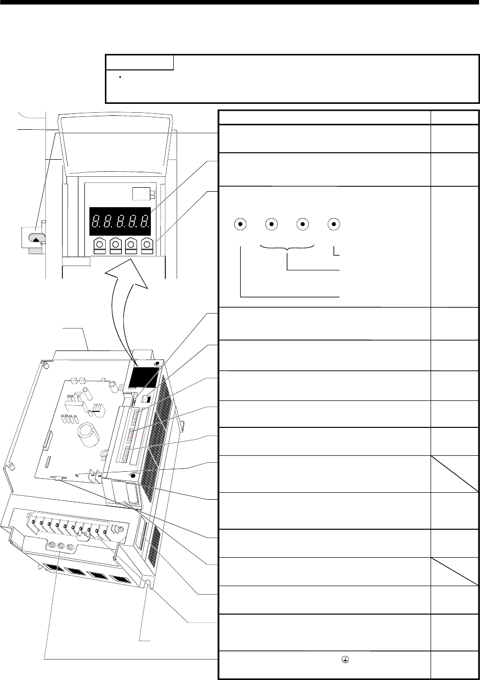
1 - 14
1. FUNCTIONS AND CONFIGURATION
(5) MR-J2S-11KA or more
POINT
The servo amplifier is shown without the front cover. For removal of the
front cover, refer to section 1. 7. 2.
MODE UP DOWN SET
MODE UP DOWN SET
Battery holder
Contains the battery for absolute position data backup.
Display
The 5-digit, seven-segment LED shows the servo
status and alarm number.
Operation section
Used to perform status display, diagnostic, alarm and
parameter setting operations.
Used to set data.
Used to change the
display or data in each
mode.
Used to change the
mode.
Section15.3
Chapter6
Chapter6
Name/Application Reference
Battery connector (CON1)
Used to connect the battery for absolute position data
backup.
Communication connector (CN3)
Used to connect a command device (RS232C)
I/O signal connector (CN1A)
Used to connect digital I/O signals.
I/O signal connector (CN1B)
Used to connect digital I/O signals.
Charge lamp
Lit to indicate that the main circuit is charged.
While this lamp is lit, do not reconnect the cables.
Control circuit terminal block (TE2)
Used to connect the control circuit power supply.
Encoder connector (CN2)
Used to connect the servo motor encoder.
Name plate
Main circuit terminal block (TE1)
Used to connect the input power supply, regenerative
brake option and servo motor.
Protective earth (PE) terminal ( )
Ground terminal.
Section15.3
Cooling fan
Fixed part
(4 places)
Section3.3
Section11.1
Section3.3
Section13.1.5
Section3.3
Section3.3
Section3.3
Section13.1.5
Section1.5
Section3.7
Section11.1
Section13.1.1
Section3.10
Section11.1
Section3.7
Section11.1
Section13.1.1
Monitor output terminal (CN4)
Used to output monitor values as analog signals
for two channels.
Maker adjusting connector (CON2)
Keep this connector open.
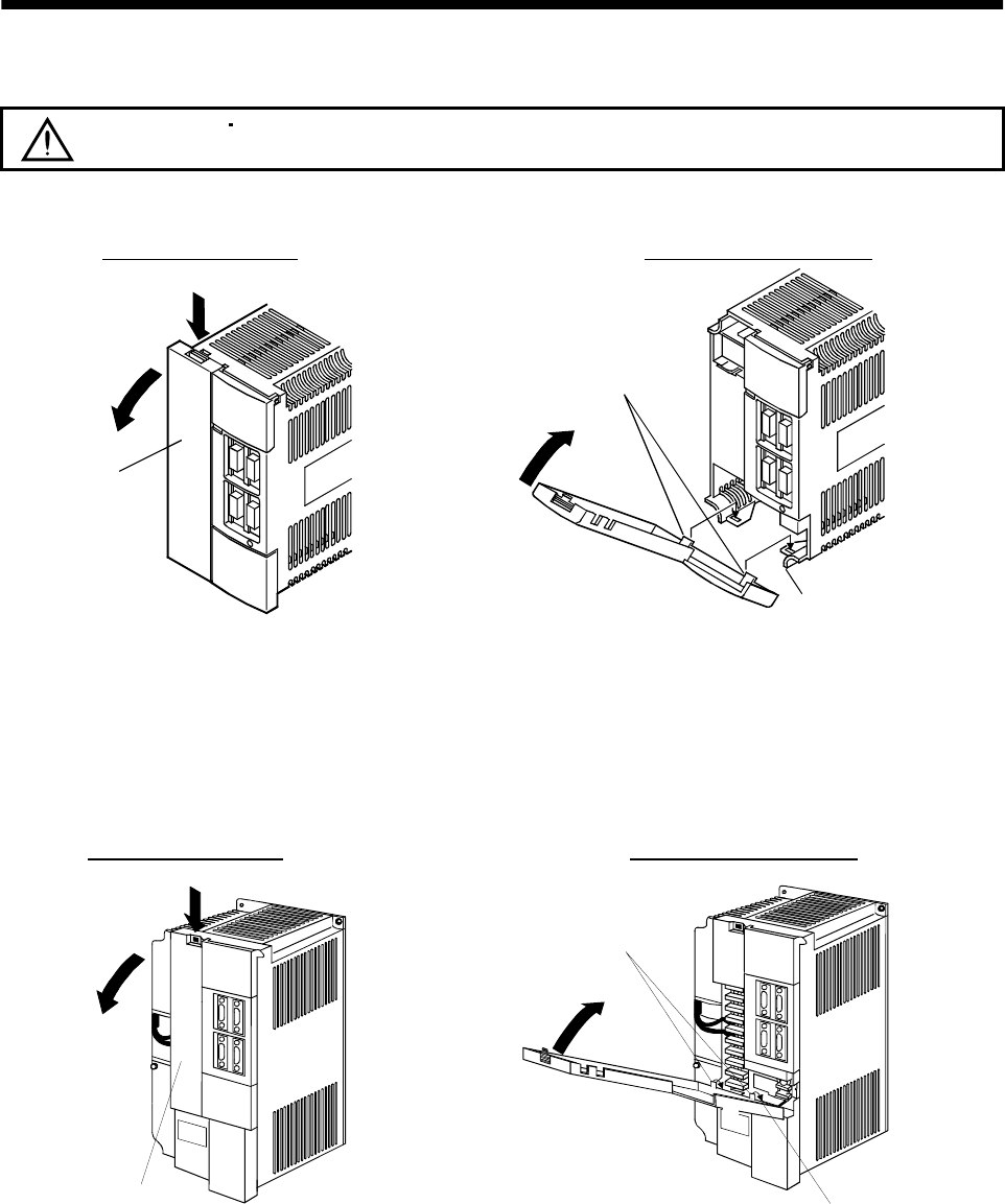
1 - 15
1. FUNCTIONS AND CONFIGURATION
1.7.2 Removal and reinstallation of the front cover
CAUTION To avoid the risk of an electric shock, do not open the front cover while power is
on.
(1) For MR-J2S-350A or less
Front cover hook
(2 places)
Front cover socket
(2 places)
2)
1)
Front cover
2)
1)
Removal of the front cover Reinstallation of the front cover
1) Insert the front cover hooks into the front cover sockets of
the servo amplifier.
2) Press the front cover against the servo amplifier until the
removing knob clicks.
1) Hold down the removing knob.
2) Pull the front cover toward you.
(2) For MR-J2S-500A
Front cover socket
(2 places)
Removal of the front cover Reinstallation of the front cover
1) Insert the front cover hooks into the front cover sockets of
the servo amplifier.
2) Press the front cover against the servo amplifier until the
removing knob clicks.
1) Hold down the removing knob.
2) Pull the front cover toward you.
2)
1)
Front cover hook
(2 places)
2)
1)
Front cover
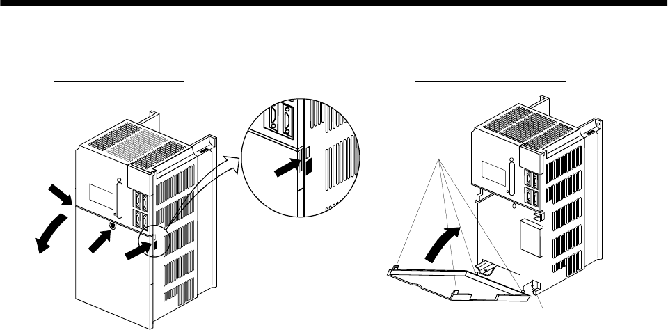
1 - 16
1. FUNCTIONS AND CONFIGURATION
(3) For MR-J2S-700A
Front cover socket
(2 places)
A)
1)
Removal of the front cover Reinstallation of the front cover
1) Insert the two front cover hooks at the bottom into the
sockets of the servo amplifier.
2) Press the front cover against the servo amplifier until the
removing knob clicks.
1) Push the removing knob A) or B), and put you
finger into the front hole of the front cover.
2) Pull the front cover toward you.
A)
2)
B)
2)
1)
Front cover
hook
(2 places)
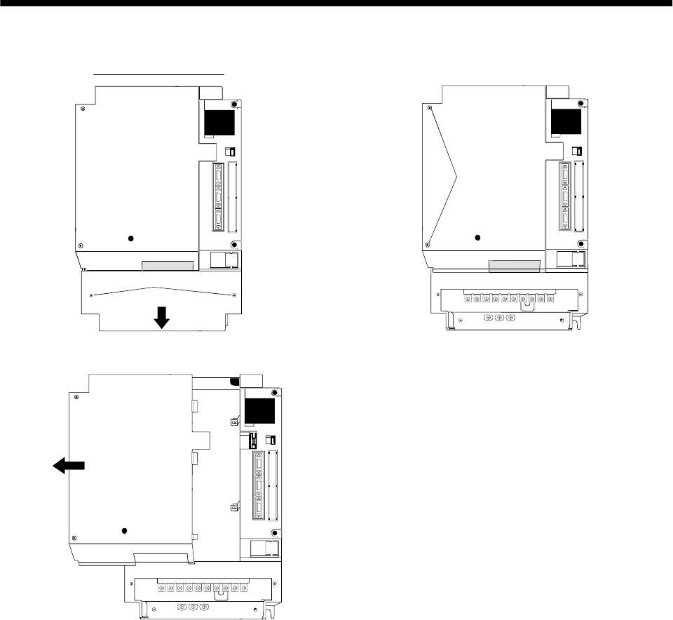
1 - 17
1. FUNCTIONS AND CONFIGURATION
(4) For MR-J2S-11KA or more
Mounting screws (2 places)
1) Remove the front cover mounting screws (2 places)
and remove the front cover.
Removal of the front cover
Mounting screws
(2 places)
2) Remove the front cover mounting screws (2 places).
3) Remove the front cover by drawing it in the direction of arrow.
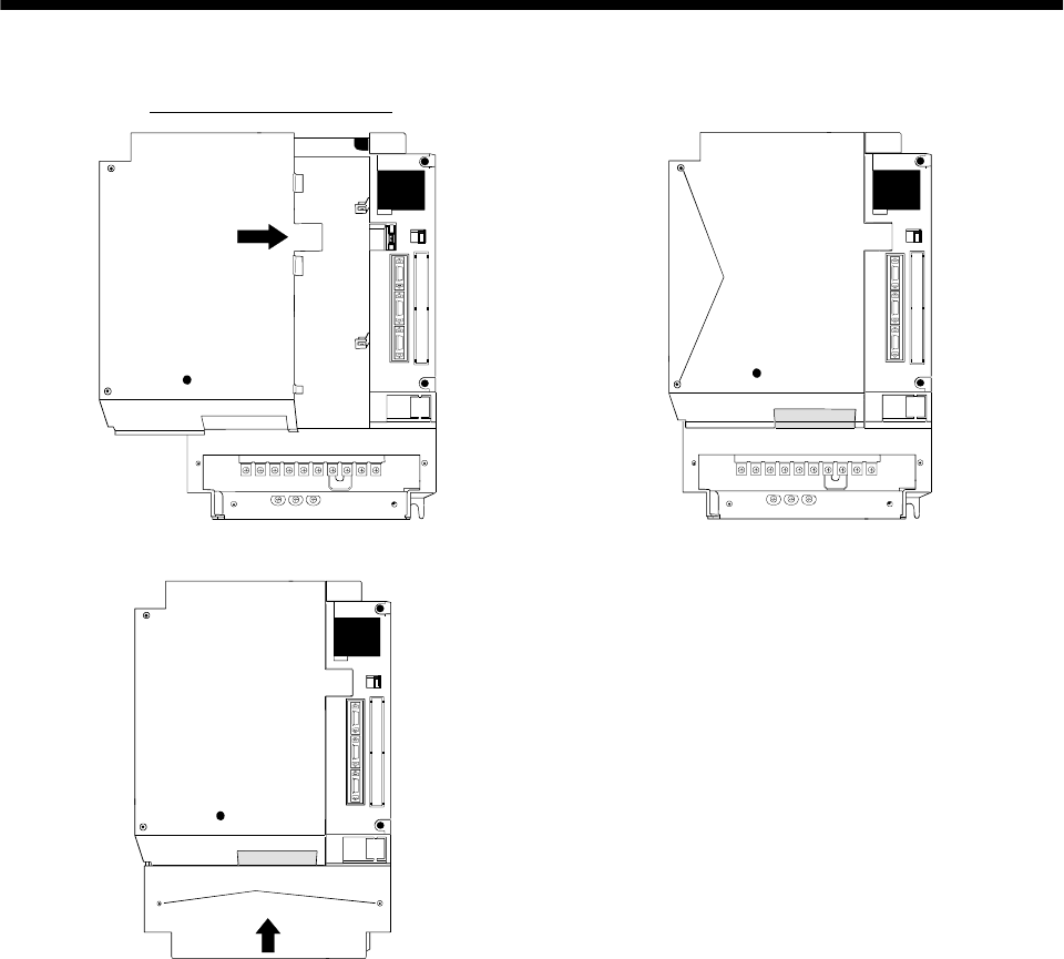
1 - 18
1. FUNCTIONS AND CONFIGURATION
1) Insert the front cover in the direction of arrow.
Reinstallation of the front cover
Mounting screws
(2 places)
2) Fix it with the mounting screws (2 places).
Mounting screws (2 places)
3) Fit the front cover and fix it with the mounting screws (2 places).
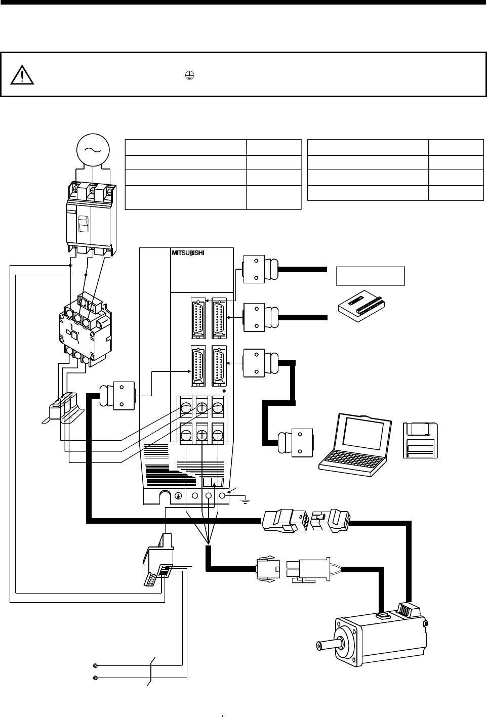
1 - 19
1. FUNCTIONS AND CONFIGURATION
1.8 Servo system with auxiliary equipment
WARNING To prevent an electric shock, always connect the protective earth (PE) terminal
(terminal marked ) of the servo amplifier to the protective earth (PE) of the control
box.
(1) MR-J2S-100A or less
(a) For 3-phase 200V to 230VAC or 1-phase 230VAC
(Note2)
3-phase 200V
to 230VAC power
supply or
1-phase 230VAC
power supply
No-fuse breaker
(NFB) or fuse
Magnetic
contactor
(MC)
To CN2
To CN3
To CN1B
Junction terminal block
To CN1A
L1
L2
L21
L11
Protective earth(PE) terminal
Servo motor
Personal
computer
UVW
MR Configurator
(Servo configuration
software
MRZJW3-SETUP151E)
Servo amplifier
Regenerative brake
option
D
P
C
CHARGE
Options and auxiliary equipment
No-fuse breaker
Magnetic contactor
MR Configurator
(Servo configuration software)
Regenerative brake option
Reference
Section 13.2.2
Section 13.2.2
Section 13.1.9
Section 13.1.1
Control circuit terminal block
(Note1)
Encoder cable
Options and auxiliary equipment Reference
Cables Section 13.2.1
Command device
(Note1)
Power supply lead
L3
Note 1. The HC-SFS, HC-RFS series have cannon connectors.
2. A 1-phase 230VAC power supply may be used with the servo amplifier of MR-J2S-70A or less.
For 1-phase 230VAC, connect the power supply to L1 L2 and leave L3 open.
Power
factor
improving
reactor
(FR-BAL)
Power factor improving reactor Section 13.2.3
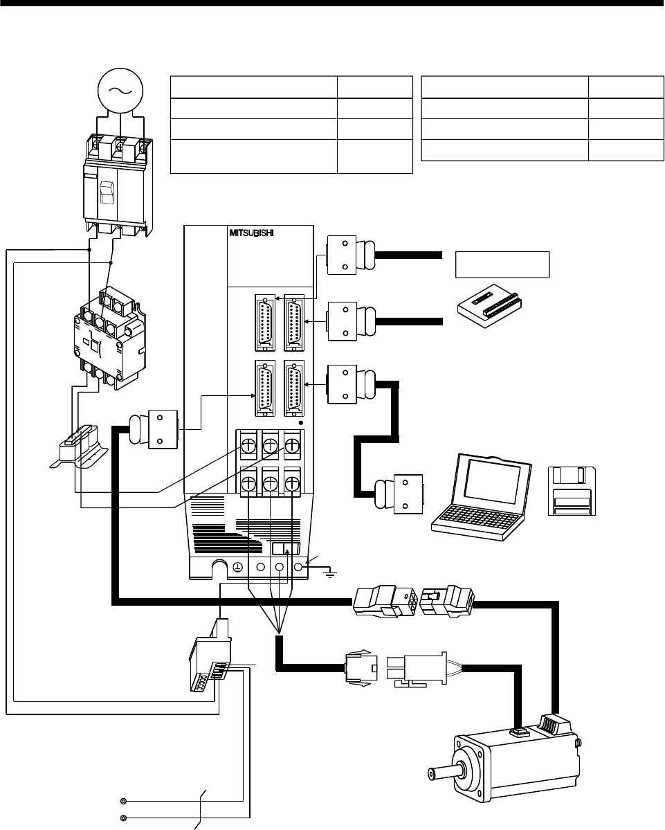
1 - 20
1. FUNCTIONS AND CONFIGURATION
(b) For 1-phase 100V to 120VAC
1-phase 100V
to 120VAC
power supply
No-fuse breaker
(NFB) or fuse
Magnetic
contactor
(MC)
To CN2
To CN3
To CN1B
Junction terminal block
To CN1A
L21
L11
Protective earth(PE) terminal
Servo motor
Personal
computer
UVW
MR Configurator
(Servo configuration
software
MRZJW3-SETUP151E)
Servo amplifier
Regenerative brake
option
D
P
C
CHARGE
Options and auxiliary equipment
No-fuse breaker
Magnetic contactor
MR Configurator
(Servo configuration software)
Regenerative brake option
Reference
Section 13.2.2
Section 13.2.2
Section 13.1.9
Section 13.1.1
Control circuit terminal block
(Note)
Encoder cable
Note. The HC-SFS, HC-RFS series have cannon connectors.
Options and auxiliary equipment Reference
Cables Section 13.2.1
Command device
(Note)
Power supply lead
L1
L2
Power
factor
improving
reactor
(FR-BAL)
Power factor improving reactor Section 13.2.3
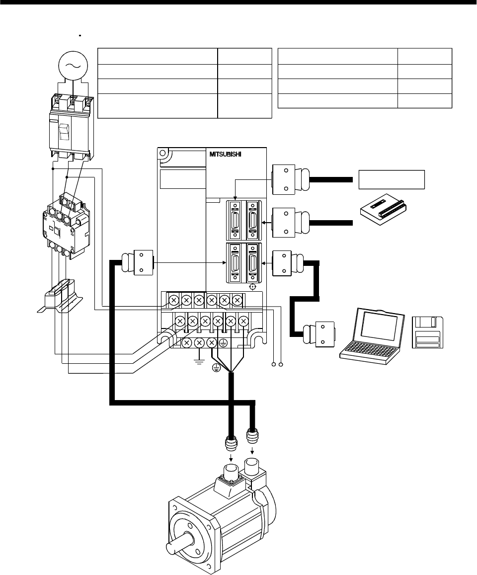
1 - 21
1. FUNCTIONS AND CONFIGURATION
(2) MR-J2S-200A MR-J2S-350A or more
Power
factor
improving
reactor
(FR-BAL)
3-phase 200V
to 230VAC
power supply
No-fuse
breaker
(NFB) or
fuse
Magnetic
contactor
(MC)
To CN2 To CN3
To CN1B
Junction terminal
block
To CN1A
L1
L2
L3
L21
L11
Servo amplifier
Regenerative brake option
PC
UVW
Options and auxiliary equipment
No-fuse breaker
Magnetic contactor
MR Configurator
(Servo configuration software)
Regenerative brake option
Reference
Section 13.2.2
Section 13.2.2
Section 13.1.9
Section 13.1.1
Options and auxiliary equipment Reference
Personal
computer
MR Configurator
(Servo
configuration
software
MRZJW3-
SETUP151E)
Cables Section 13.2.1
Command device
Power factor improving reactor Section 13.2.3
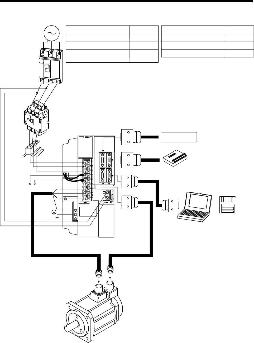
1 - 22
1. FUNCTIONS AND CONFIGURATION
(3) MR-J2S-500A
To CN1A
Options and auxiliary equipment
No-fuse breaker
Magnetic contactor
MR Configurator
(Servo configuration software)
Regenerative brake option
Reference
Section 13.2.2
Section 13.2.2
Section 13.1.9
Section 13.1.1
Options and auxiliary equipment Reference
Cables Section 13.2.1
Power factor improving reactor Section 13.2.3
3-phase 200V
to 230VAC
power supply
No-fuse
breaker
(NFB) or
fuse
Magnetic
contactor
(MC)
Power
factor
improving
reactor
(FA-BAL)
Servo amplifier
L1
L2
L3
C P
Regenerative brake
option
L11
L21
U
V
W
To CN1B
To CN3
To CN2
Personal
computer
MR Configurator
(Servo
configuration
software
MRZJW3-
SETUP151E)
Junction terminal
block
Command device
(Note)
Note. When using the regenerative brake option, remove the lead wires of the built-in regenerative brake resistor.
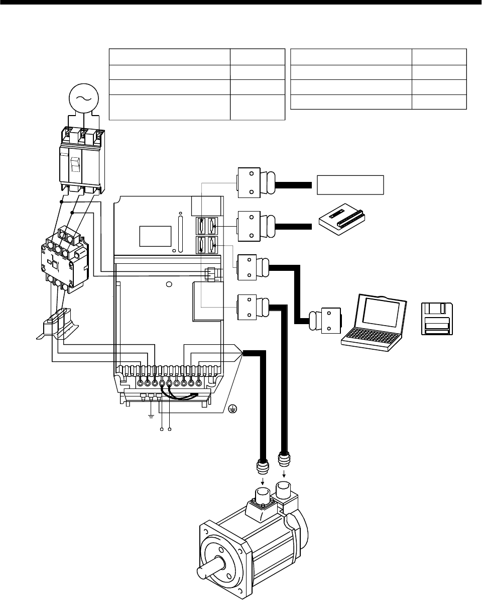
1 - 23
1. FUNCTIONS AND CONFIGURATION
(4) MR-J2S-700A
W
V
Options and auxiliary equipment
No-fuse breaker
Magnetic contactor
MR Configurator
(Servo configuration software)
Regenerative brake option
Reference
Section 13.2.2
Section 13.2.2
Section 13.1.9
Section 13.1.1
Options and auxiliary equipment Reference
Cables Section 13.2.1
Power factor improving reactor Section 13.2.3
3-phase 200V
to 230VAC
power supply
No-fuse
breaker
(NFB) or
fuse
Magnetic
contactor
(MC)
Power
factor
improving
reactor
(FA-BAL)
L1
L2
L3U
(Note) Regenerative brake
option
C P
Servo amplifier
To CN1A
To CN1B
To CN3
To CN2
Personal
computer
MR Configurato
r
(Servo
configuration
software
MRZJW3-
SETUP151E)
L11
L21 Junction terminal
block
Command device
Note. When usin
g
the re
g
enerative brake option, remove the lead wires of the built-in re
g
enerative brake resistor.
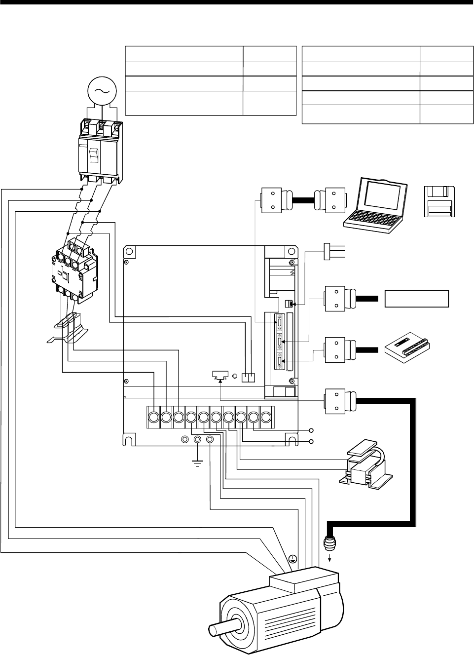
1 - 24
1. FUNCTIONS AND CONFIGURATION
(5) MR-J2S-11KA or more
L11
L21
L2
L1
L3
MITSUBISH I
UVW
BV
BU
C
P
To CN1A
To CN1B
Options and auxiliary equipment
No-fuse breaker
Magnetic contactor
MR Configurator
(Servo configuration software)
Regenerative brake option
Reference
Section 13.2.2
Section 13.2.2
Section 13.1.9
Section 13.1.1
Options and auxiliary equipment Reference
Cables Section 13.2.1
Power factor improving reactor Section 13.2.3
Power factor improving
DC reactor Section 13.2.4
3-phase 200V
to 230VAC
power supply
No-fuse
breaker
(NFB) or
fuse
Magnetic
contactor
(MC)
Power
factor
improving
reactor
(FA-BAL)
Regenerative brake
option
Command device
Junction terminal
block
Personal
computer
MR Configurator
(Servo
configuration
software
MRZJW3-
SETUP151E)
(Note2)
Power factor
improving DC reactor
(FR-BEL)
To CN4
To CN2
(Note1)
BW
(Note2)
Analog monitor
Servo motor
series
Note1. There is no BW when the HA-LFS11K2 is used.
2. Use either the FR-BAL or FR-BEL power factor improving reactor.
To CN3
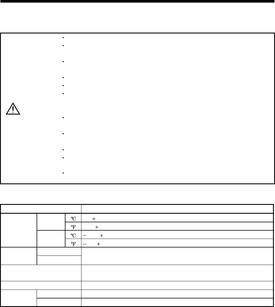
2 - 1
2. INSTALLATION
2. INSTALLATION
CAUTION
Stacking in excess of the limited number of products is not allowed.
Install the equipment to incombustibles. Installing them directly or close to
combustibles will led to a fire.
Install the equipment in a load-bearing place in accordance with this Instruction
Manual.
Do not get on or put heavy load on the equipment to prevent injury.
Use the equipment within the specified environmental condition range.
Provide an adequate protection to prevent screws, metallic detritus and other
conductive matter or oil and other combustible matter from entering the servo
amplifier.
Do not block the intake/exhaust ports of the servo amplifier. Otherwise, a fault may
occur.
Do not subject the servo amplifier to drop impact or shock loads as they are
precision equipment.
Do not install or operate a faulty servo amplifier.
When the product has been stored for an extended period of time, consult
Mitsubishi.
When treating the servo amplifier, be careful about the edged parts such as the
corners of the servo amplifier.
2.1 Environmental conditions
Environment Conditions
[]0 to 55 (non-freezing)
Operation [] 32 to 131 (non-freezing)
[ ] 20 to 65 (non-freezing)
Ambient
temperature Storage []4 to 149 (non-freezing)
Operation
Ambient
humidity Storage 90%RH or less (non-condensing)
Ambience Indoors (no direct sunlight)
Free from corrosive gas, flammable gas, oil mist, dust and dirt
Altitude Max. 1000m (3280 ft) above sea level
[m/s2] 5.9 [m/s2] or less
Vibration [ft/s2] 19.4 [ft/s2] or less
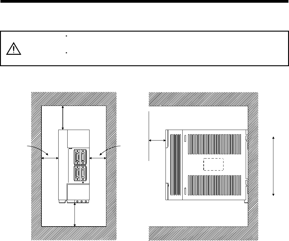
2 - 2
2. INSTALLATION
2.2 Installation direction and clearances
CAUTION
The equipment must be installed in the specified direction. Otherwise, a fault may
occur.
Leave specified clearances between the servo amplifier and control box inside
walls or other equipment.
(1) Installation of one servo amplifier
Control box Control box
10mm
(0.4 in.)
or more
10mm
(0.4 in.)
or more
40mm
(1.6 in.)
or more
Servo amplifier
40mm
(1.6 in.)
or more
Wiring clearance
70mm
(2.8 in.) Top
Bottom
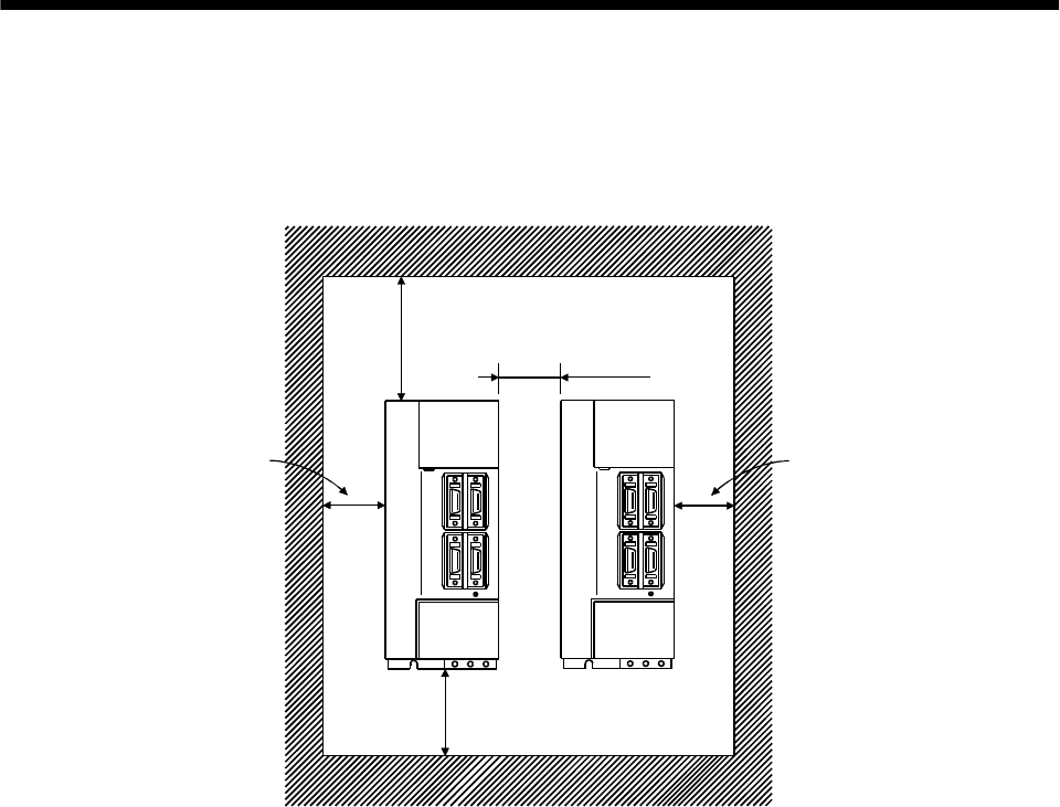
2 - 3
2. INSTALLATION
(2) Installation of two or more servo amplifiers
Leave a large clearance between the top of the servo amplifier and the internal surface of the control
box, and install a fan to prevent the internal temperature of the control box from exceeding the
environmental conditions.
Control box
30mm
(1.2 in.)
or more
30mm
(1.2 in.)
or more
10mm
(0.4 in.)
or more
40mm
(1.6 in.)
or more
100mm
(4.0 in.)
or more
Servo
amplifier
(3) Others
When using heat generating equipment such as the regenerative brake option, install them with full
consideration of heat generation so that the servo amplifier is not affected.
Install the servo amplifier on a perpendicular wall in the correct vertical direction.
2.3 Keep out foreign materials
(1) When installing the unit in a control box, prevent drill chips and wire fragments from entering the
servo amplifier.
(2) Prevent oil, water, metallic dust, etc. from entering the servo amplifier through openings in the control
box or a fan installed on the ceiling.
(3) When installing the control box in a place where there are much toxic gas, dirt and dust, conduct an
air purge (force clean air into the control box from outside to make the internal pressure higher than
the external pressure) to prevent such materials from entering the control box.

2 - 4
2. INSTALLATION
2.4 Cable stress
(1) The way of clamping the cable must be fully examined so that flexing stress and cable's own mass
stress are not applied to the cable connection.
(2) For use in any application where the servo motor moves, fix the cables (encoder, power supply, brake)
supplied with the servo motor, and flex the optional encoder cable or the power supply and brake
wiring cables. Use the optional encoder cable within the flexing life range. Use the power supply and
brake wiring cables within the flexing life of the cables.
(3) Avoid any probability that the cable sheath might be cut by sharp chips, rubbed by a machine corner
or stamped by workers or vehicles.
(4) For installation on a machine where the servo motor will move, the flexing radius should be made as
large as possible. Refer to section 12.4 for the flexing life.
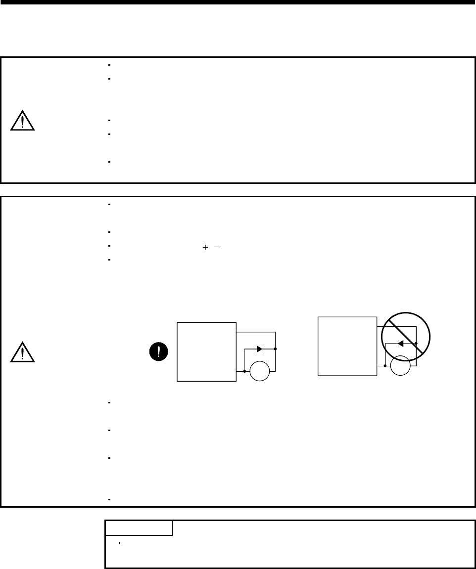
3 - 1
3. SIGNALS AND WIRING
3. SIGNALS AND WIRING
WARNING
Any person who is involved in wiring should be fully competent to do the work.
Before starting wiring, switch power off, then wait for more than 15 minutes, and
after the charge lamp has gone off, make sure that the voltage is safe in the tester
or like. Otherwise, you may get an electric shock.
Ground the servo amplifier and the servo motor securely.
Do not attempt to wire the servo amplifier and servo motor until they have been
installed. Otherwise, you may get an electric shock.
The cables should not be damaged, stressed excessively, loaded heavily, or
pinched. Otherwise, you may get an electric shock.
CAUTION
Wire the equipment correctly and securely. Otherwise, the servo motor may
misoperate, resulting in injury.
Connect cables to correct terminals to prevent a burst, fault, etc.
Ensure that polarity ( , ) is correct. Otherwise, a burst, damage, etc. may occur.
The surge absorbing diode installed to the DC relay designed for control output
should be fitted in the specified direction. Otherwise, the signal is not output due to
a fault, disabling the emergency stop (EMG) and other protective circuits.
Control output
signal
COM
(DC24V)
Servo amplifier
RA
RA
Servo
Amplifier
COM
(24VDC)
Control
output
signal
Use a noise filter, etc. to minimize the influence of electromagnetic interference,
which may be given to electronic equipment used near the servo amplifier.
Do not install a power capacitor, surge suppressor or radio noise filter (FR-BIF
option) with the power line of the servo motor.
When using the regenerative brake resistor, switch power off with the alarm signal.
Otherwise, a transistor fault or the like may overheat the regenerative brake
resistor, causing a fire.
Do not modify the equipment.
POINT
CN1A, CN1B, CN2 and CN3 have the same shape. Wrong connection of
the connectors will lead to a failure. Connect them correctly.
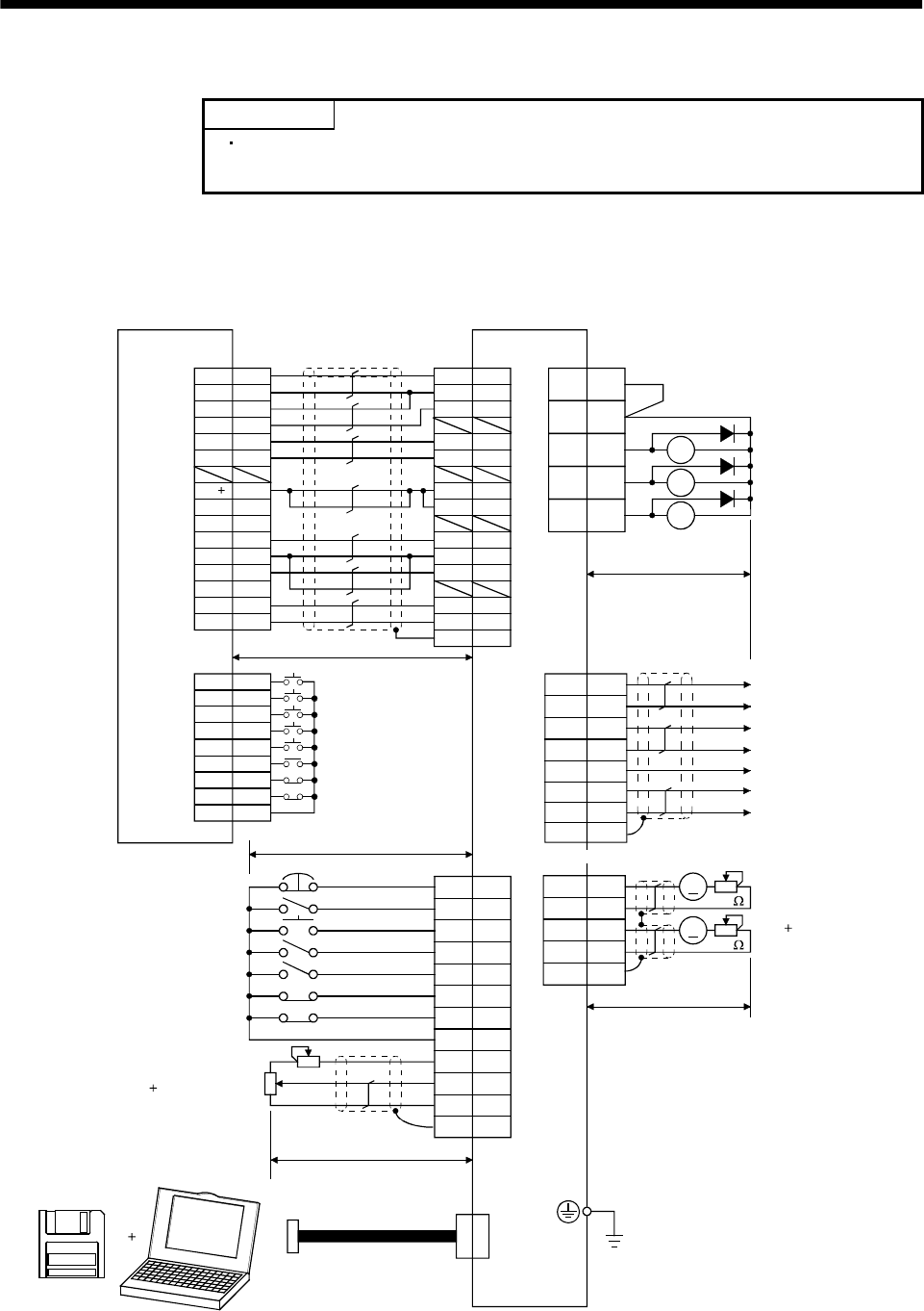
3 - 2
3. SIGNALS AND WIRING
3.1 Standard connection example
POINT
Refer to Section 3.7.1 for the connection of the power supply system and to
Section 3.8 for connection with the servo motor.
3.1.1 Position control mode
(1) FX-10GM
VDD
RA1
RA2
RA3
18
15
5
14
8
9
16
17
12
EMG
SON
RES
PC
TL
LSP
LSN
SD
SG
P15R
LG
10
11
ALM
19 ZSP
6TLC
CN1B
13 COM
3
TLA
CN1A
4
13
3
SD
LG
14
MO1
LG
MO2
CN3
A
A
18
19
9
4
14
11
9
3
10
2
8
20
START
ST-
FWD
RVS
DOG
LSR
COM1
1
2
4
5
6
8
9,19
3
7
ZRN
LSF
FX-10GM
1
CN3
Positioning module
SVRDY
COM2
COM2
SVEND
COM4
PG0
24
VC
FPO
FP
COM5
RP
RP0
CLR
4
(Note 3, 6) Emergency stop
Servo-on
Reset
Proportion control
Torque limit selection
(Note 6) Forward rotation stroke end
Reverse rotation stroke end
Upper limit setting
Analog torque limit
(Note 11)
MR Configurator
(Servo configuration
software)
Personal
computer
10V/max. torque
(Note 10) 2m(6.5ft) max.
10m(32ft) max.
2m(6.5ft) max.
(Note 8)
Communication cable
Servo amplifier
(Note 4, 9) (Note 4)
CN1A CN1B
1
2
12
11
14
13
7,17
8,18
5
6
9,19
16
15
3
(Note 12)
(Note 2, 5) (Note 7)
Trouble
Zero speed
Limiting torque
(Note 4, 9)
7
6
16
Plate
17
LB
LA
LAR
SD
LBR
Encoder A-phase pulse
(differential line driver)
Encoder B-phase pulse
(differential line driver)
(Note 4, 9,14)(Note 4, 9)
Plate
Plate
(Note 8)
Analog monitor
Max. 1mA
Reading in both
directions
10k
10k
2m (6.5ft) max.
(Note 4, 9) (Note 1)
Plate
RD
COM
INP
P15R
OP
COM
PP
SG
NP
CR
SD
SG
COM3
OPC
(Note 13)
5
15
LZ
LZR
Encoder Z-phase pulse
(differential line driver)
10m (32ft) or less
LG 1 Control common
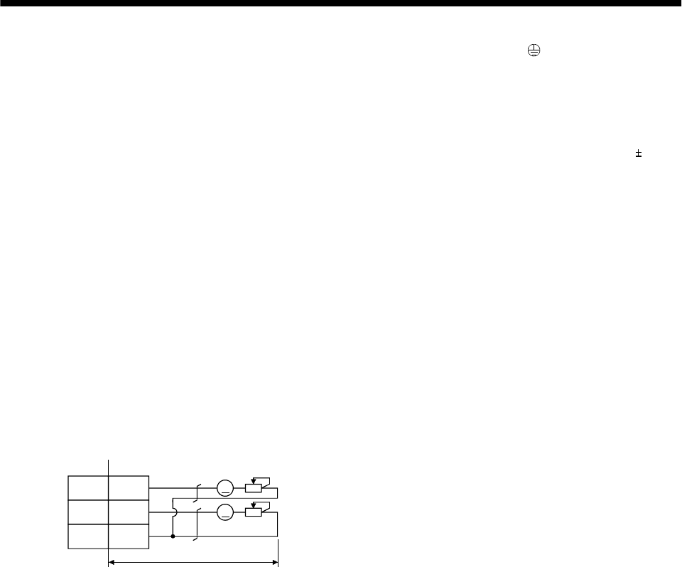
3 - 3
3. SIGNALS AND WIRING
Note 1. To prevent an electric shock, always connect the protective earth (PE) terminal (terminal marked ) of the servo amplifier to
the protective earth (PE) of the control box.
2. Connect the diode in the correct direction. If it is connected reversely, the servo amplifier will be faulty and will not output
signals, disabling the emergency stop (EMG) and other protective circuits.
3. The emergency stop switch (normally closed contact) must be installed.
4. CN1A, CN1B, CN2 and CN3 have the same shape. Wrong connection of the connectors will lead to a fault.
5. The sum of currents that flow in the external relays should be 80mA max. If it exceeds 80mA, externally supply 24VDC 10%,
200mA power for the interface. 200mA is a value applicable when all I/O signals are used. Reducing the number of I/O points
decreases the current capacity. Refer to the current necessary for the interface described in Section 3.6.2. Connect the external
24VDC power supply if the output signals are not used.
6. When starting operation, always turn on emergency stop (EMG) and Forward/Reverse rotation stroke end (LSP/LSN).
(Normally closed contacts)
7. Trouble (ALM) turns on in normal alarm-free condition. When this signal is switched off (at occurrence of an alarm), the output
of the programmable controller should be stopped by the sequence program.
8. When connecting the personal computer together with analog monitor 1 (MO1) and analog monitor 2 (MO2) on the 7kW or less
servo amplifier, use the maintenance junction card (MR-J2CN3TM). (Refer to Section 13.1.5.).
9. The pins with the same signal name are connected in the servo amplifier.
10. This length applies to the command pulse train input in the opencollector system. It is 10m (32ft) or less in the differential line
driver system.
11. Use MRZJW3-SETUP 151E.
12. When using the internal power supply (VDD), always connect VDD-COM. Do not connect them when supplying external
power. Refer to Section 3.6.2.
13. Connect to CN1A-10 when using the junction terminal block (MR-TB20).
14. For the 11kW or more servo amplifier, analog monitor 1 (MO1) and analog monitor 2 (MO2) are replaced by CN4.
CN4
A
A
MO1
MO2
LG
1
2
4
2m (6.5ft) or less
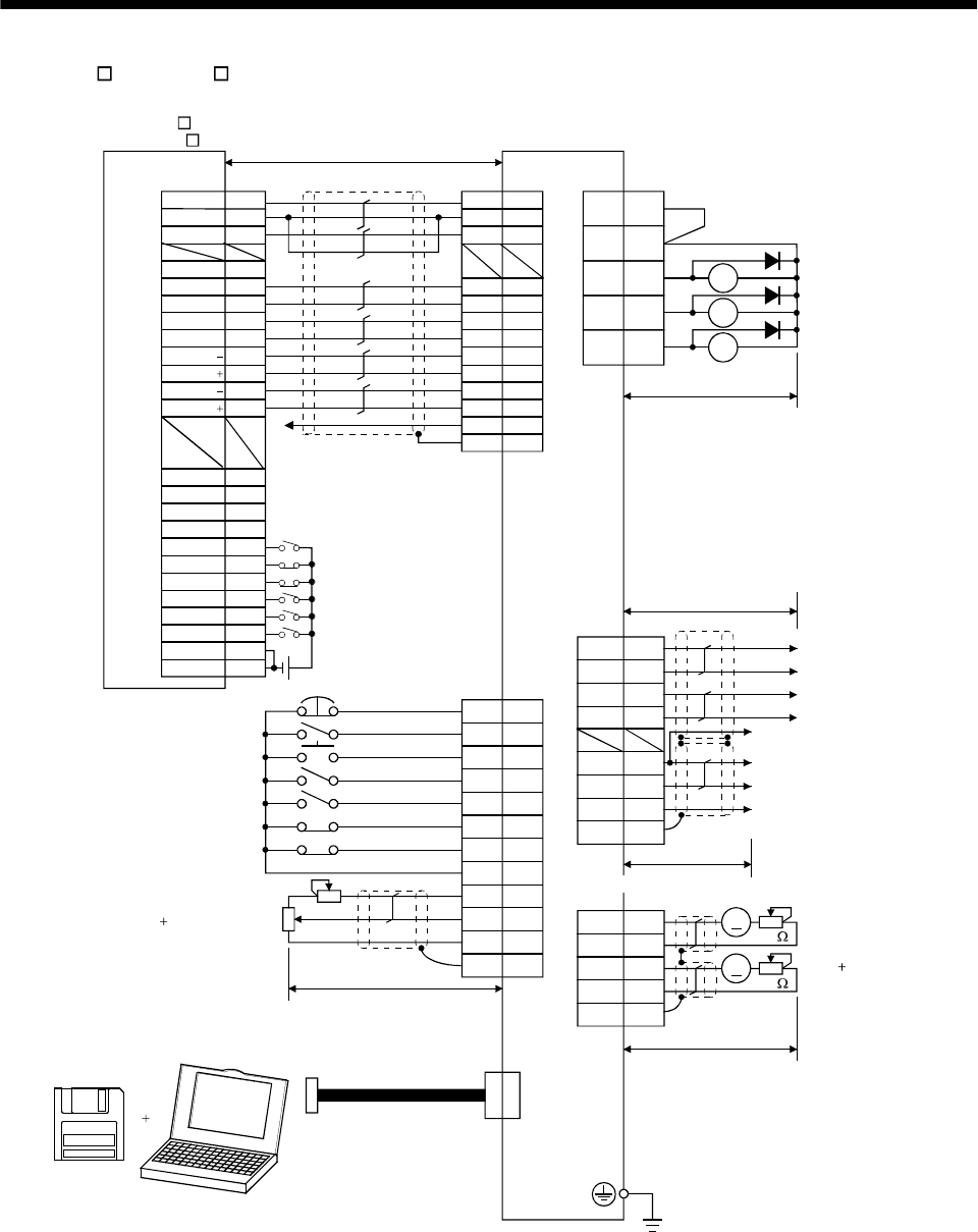
3 - 4
3. SIGNALS AND WIRING
(2) AD75P (A1SD75P )
VDD
RA1
RA2
RA3
18
15
5
14
8
9
16
17
1
11
EMG
SON
RES
PC
TL
LSP
LSN
SD
SG
P15R
LG
10
12
ALM
19 ZSP
6TLC
14
7
16
17
4
LA
LAR
LB
LBR
LG
OP
P15R
SD
1
6
CN1B
CN3
13 COM
3
TLA
(Note 4,9)
CN1A
4
13
3
SD
LG
14
MO1
LG
MO2
CN3
A
A
COM
INP
LZ
CR
PG
NP
NG
RD
SG
PP
LZR
SD
LG 1
26
8
24
5
21
4
22
7
23
3
25
6
1
20
12
14
35
16
DOG
COM
RLS
START
CHG
FLS
13
15
11
STOP
COM
2
36
19
DC24V
Positioning module
AD75P
(A1SD75P )
Ready
COM
INPS
PGO(24V)
PGO(5V)
PGO COM
CLEAR
CLEAR COM
PULSE F
PULSE F
PULSE R
PULSE R
PULSE F
PULSE R
(Note 10) 10m(32ft) max. Servo amplifier
(Note 4,9)
CN1A
(Note 4)
CN1B
(Note 12)
(Note 7)
(Note 2,5) Trouble
Zero speed
Limiting torque
Encoder A-phase pulse
(differential line driver)
Encoder B-phase pulse
(differential line driver)
Control common
Encoder Z-phase pulse
(open collector)
(Note 4,9)
(Note 4,9,14)
Plate
Plate
(Note 3, 6) Emergency stop
Servo-on
Reset
Proportion control
Torque limit selection
(Note 6) Forward rotation stroke end
Reverse rotation stroke end
Upper limit setting
Analog torque limit
10V/max. torque
(Note 11)
MR Configurator
(Servo configuration
software)
Personal
computer (Note 8)
Communication cable
(Note 1)
(Note 8)
Analog monitor
Max. 1mA
Reading in both
directions
2m(6.5ft) max.
10k
10k
Plate
19
9
18
5
15
2
10
12
3
8
13
Plate
(Note 4,9)
2m(6.5ft) max.
(Note 13)
PULSE COM
PULSE COM
2m(6.5ft) or less
10m(32ft) or less
10m(32ft) or less
Control common
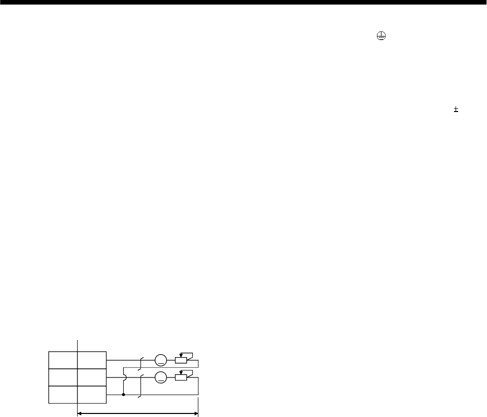
3 - 5
3. SIGNALS AND WIRING
Note 1. To prevent an electric shock, always connect the protective earth (PE) terminal (terminal marked ) of the servo amplifier to
the protective earth (PE) of the control box.
2. Connect the diode in the correct direction. If it is connected reversely, the servo amplifier will be faulty and will not output
signals, disabling the emergency stop (EMG) and other protective circuits.
3. The emergency stop switch (normally closed contact) must be installed.
4. CN1A, CN1B, CN2 and CN3 have the same shape. Wrong connection of the connectors will lead to a fault.
5. The sum of currents that flow in the external relays should be 80mA max. If it exceeds 80mA, externally supply 24VDC 10%,
200mA power for the interface. 200mA is a value applicable when all I/O signals are used. Reducing the number of I/O points
decreases the current capacity. Refer to the current necessary for the interface described in Section 3.6.2. Connect the external
24VDC power supply if the output signals are not used.
6. When starting operation, always turn on emergency stop (EMG) and forward/reverse rotation stroke end (LSP/LSN). (Normally
closed contacts)
7. Trouble (ALM) turns on in normal alarm-free condition. When this signal is switched off (at occurrence of an alarm), the output
of the controller should be stopped by the sequence program.
8. When connecting the personal computer together with analog monitor 1 (MO1) and analog monitor 2 (MO2) on the 7kW or less
servo amplifier, use the maintenance junction card (MR-J2CN3TM). (Refer to Section 13.1.5)
9. The pins with the same signal name are connected in the servo amplifier.
10. This length applies to the command pulse train input in the differential line driver system.
It is 2m (6.5ft) or less in the opencollector system.
11. Use MRZJW3-SETUP 151E.
12. When using the internal power supply (VDD), always connect VDD-COM. Do not connect them when supplying external
power. Refer to Section 3.6.2.
13. This connection is not required for the AD75P. Depending on the used positioning module, however, it is recommended to
connect the LG and control common terminals of the servo amplifier to enhance noise immunity.
14. For the 11kW or more servo amplifier, Analog monitor 1 (MO1) and Analog monitor 2 (MO2) are replaced by CN4.
CN4
A
A
MO1
MO2
LG
1
2
4
2m (6.5ft) or less
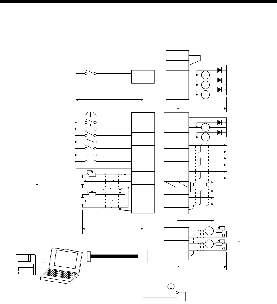
3 - 6
3. SIGNALS AND WIRING
3.1.2 Speed control mode
RA1
RA2
RA3
18
10
SP1
SG
CN1A
15
5
14
8
9
16
17
1
11
EMG
SON
RES
ST1
ST2
LSP
LSN
SD
SG
P15R
LG
10
2
ALM
19 ZSP
6TLC
15
5
14
7
16
17
4
LZ
LZR
LA
LAR
LB
LBR
LG
OP
P15R
SD
1
6
CN3
13
8
7SP2
VC
12TLA
19
18 SA
RD
RA5
RA4
CN1A
3VDD
COM
9COM
4
13
3
SD
LG
14
MO1
LG
MO2
CN3
A
A
Speed selection 1
(Note 3, 6) Emergency stop
Servo-on
Reset
Forward rotation start
Reverse rotation start
(Note 6) Forward rotation stroke end
Reverse rotation stroke end
Speed selection 2
10m(32ft) max.
Upper limit setting
(Note 10) Analog torque limit
10V/max. torque
Upper limit setting
Analog speed command
10V/rated speed
2m(6.5ft) max.
Plate Plate
(Note 11)
MR Configurator
(Servo configuration
software)
Personal
computer
(Note 4,9)
CN1B
(Note 4)
(Note 12)
(Note 7)
Trouble
Zero speed
Limiting torque
(Note 2,5)
(Note 4,9) (Note 4,9)
Speed reached
Ready
Control common
Encoder Z-phase pulse
(open collector)
Encoder Z-phase pulse
(differential line driver)
Encoder A-phase pulse
(differential line driver)
Encoder B-phase pulse
(differential line driver)
(Note 4,9,14)
Plate
(Note 8)
Communication cable
2m(6.5ft) max.
(Note 8)
Analog monitor
Max. 1mA
Reading in
both directions
10k
10k
(Note 1)
Servo amplifier
(Note 4,9)
(Note 13)
CN1B
2m(6.5ft) or less
10m(32ft) or less
Control common
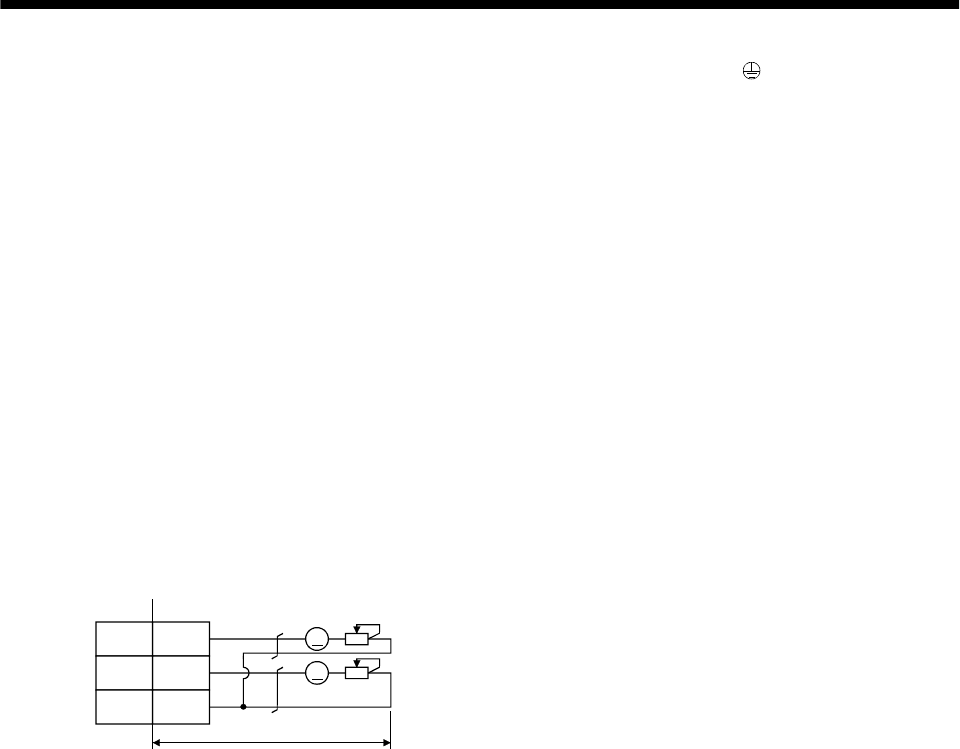
3 - 7
3. SIGNALS AND WIRING
Note 1. To prevent an electric shock, always connect the protective earth (PE) terminal (terminal marked ) of the servo amplifier to
the protective earth (PE) of the control box.
2. Connect the diode in the correct direction. If it is connected reversely, the servo amplifier will be faulty and will not output
signals, disabling the emergency stop (EMG) and other protective circuits.
3. The emergency stop switch (normally closed contact) must be installed.
4. CN1A, CN1B, CN2 and CN3 have the same shape. Wrong connection of the connectors will lead to a fault.
5. The sum of currents that flow in the external relays should be 80mA max. If it exceeds 80mA, externally supply 24VDC 10%,
200mA power for the interface. 200mA is a value applicable when all I/O signals are used. Reducing the number of I/O points
decreases the current capacity. Refer to the current necessary for the interface described in Section 3.6.2. Connect the external
24VDC power supply if the output signals are not used.
6. When starting operation, always turn on emergency stop (EMG) and forward/reverse rotation stroke end (LSP/LSN). (Normally
closed contacts)
7. Trouble (ALM) turns on in normal alarm-free condition.
8. When connecting the personal computer together with Analog monitor 1 (MO1) and analog monitor 2 (MO2) on the 7kW or less
servo amplifier, use the maintenance junction card (MR-J2CN3TM). (Refer to Section 13.1.5)
9. The pins with the same signal name are connected in the servo amplifier.
10. By setting parameters No.43 to 48 to make TL available, TLA can be used.
11. Use MRZJW3-SETUP 151E.
12. When using the internal power supply (VDD), always connect VDD-COM. Do not connect them when supplying external
power. Refer to Section 3.6.2.
13. Use an external power supply when inputting a negative voltage.
14. For the 11kW or more servo amplifier, analog monitor 1 (MO1) and analog monitor 2 (MO2) are replaced by CN4.
CN4
A
A
MO1
MO2
LG
1
2
4
2m (6.5ft) or less
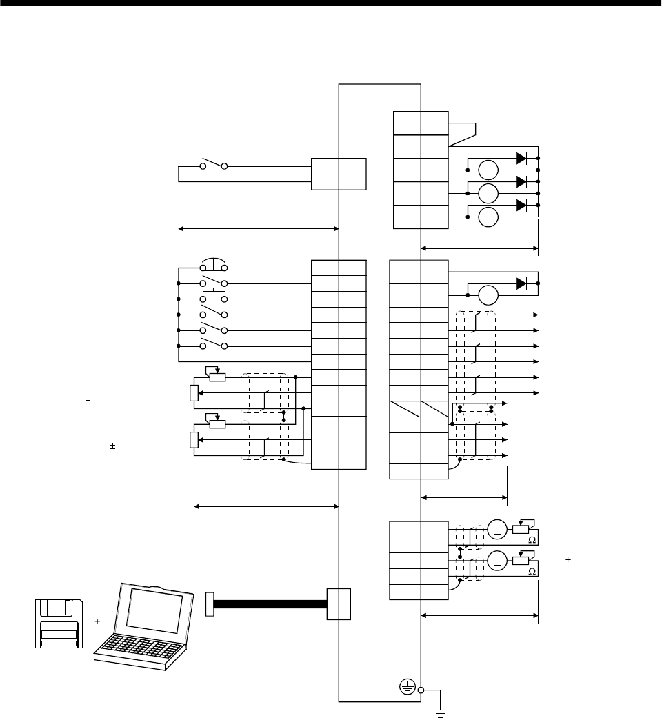
3 - 8
3. SIGNALS AND WIRING
3.1.3 Torque control mode
RA1
RA2
RA3
18
10
SP1
SG
15
5
14
9
8
10
1
11
EMG
SON
RES
RS1
RS2
SG
SD
P15R
LG
12
ALM
19 ZSP
6VLC
15
5
14
7
16
17
4
LZ
LZR
LA
LAR
LB
LBR
LG
OP
P15R
SD
1
6
CN1B
CN3
13
8
7SP2
TC
2VLA
19 RD RA4
CN1A
3VDD
COM
9COM
4
13
3
SD
LG
14
MO1
LG
MO2
CN3
A
A
Speed selection 1
Servo amplifier
CN1A
(Note 4,8)
CN1B
(Note 4)
10m(32ft) max.
(Note 4,8) (Note 4,8)
Plate
(Note 3) Emergency stop
Servo-on
Reset
Forward rotation start
Reverse rotation start
Speed selection 2
Upper limit setting
Analog speed limit
0 to 10V/rated speed
Upper limit setting
Analog torque command
8V/max. torque
(Note 9)
MR Configurator
(Servo configuration
software)
Personal
computer (Note 7)
Communication cable
2m(6.5ft) max.
Plate
Plate
(Note 7)
Analog monitor
Max. 1mA
Reading in both
directions
10k
10k
2m(6.5ft) max. (Note 4,8,12)
(Note 1)
Control common
Encoder Z-phase pulse
(open collector)
Encoder Z-phase pulse
(differential line driver)
Encoder A-phase pulse
(differential line driver)
Encoder B-phase pulse
(differential line driver)
(Note 10)
Trouble
Zero speed
Limiting torque
(Note 2,5)
Ready
(Note 6)
(Note 4,8)
(Note 11)
2m(6.5ft) or less
10m(32ft) or less
Control common
3 - 9
3. SIGNALS AND WIRING
Note 1. To prevent an electric shock, always connect the protective earth (PE) terminal of the (terminal marked ) servo amplifier to
the protective earth (PE) of the control box.
2. Connect the diode in the correct direction. If it is connected reversely, the servo amplifier will be faulty and will not output
signals, disabling the emergency stop (EMG) and other protective circuits.
3. The emergency stop switch(normally closed contact) must be installed.
4. CN1A, CN1B, CN2 and CN3 have the same shape. Wrong connection of the connectors will lead to a fault.
5. The sum of currents that flow in the external relays should be 80mA max. If it exceeds 80mA, externally supply 24VDC 10%,
200mA power for the interface. 200mA is a value applicable when all I/O signals are used. Reducing the number of I/O points
decreases the current capacity. Refer to the current necessary for the interface described in Section 3.6.2. Connect the external
24VDC power supply if the output signals are not used.
6. Trouble (ALM) turns on in normal alarm-free condition.
7. When connecting the personal computer together with analog monitor 1 (MO1) and analog monitor 2 (MO2) on the 7kW or less
servo amplifier, use the maintenance junction card (MR-J2CN3TM). (Refer to Section 13.1.5)
8. The pins with the same signal name are connected in the servo amplifier.
9. Use MRZJW3-SETUP 121E.
10. When using the internal power supply (VDD), always connect VDD-COM. Do not connect them when supplying external
power. Refer to Section 3.6.2.
11. Use an external power supply when inputting a negative voltage.
12. For the 11kW or more servo amplifier, analog monitor 1 (MO1) and analog monitor 2 (MO2) are replaced by CN4.
CN4
A
A
MO1
MO2
LG
1
2
4
2m (6.5ft) or less
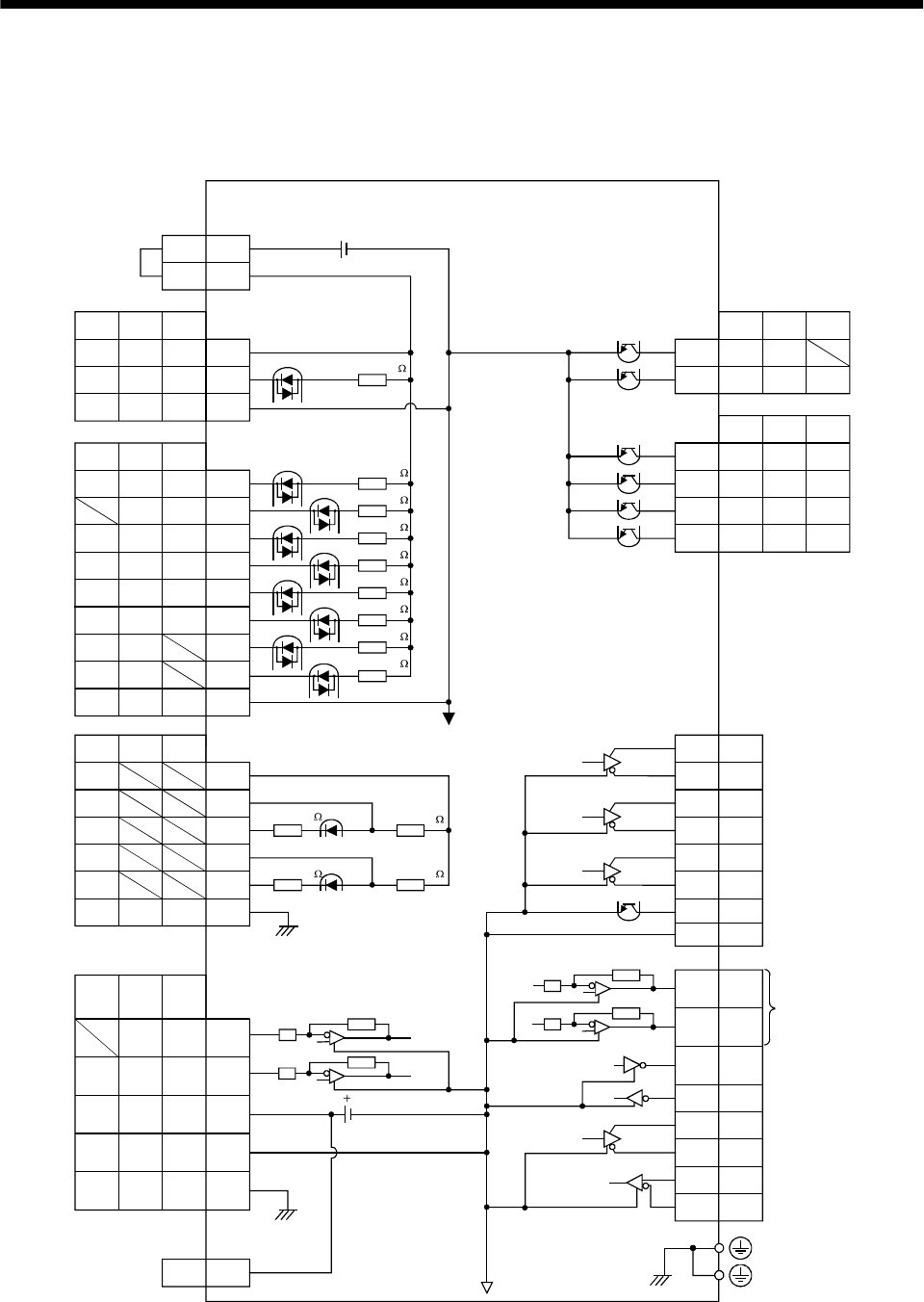
3 - 10
3. SIGNALS AND WIRING
3.2 Internal connection diagram of servo amplifier
The following is the internal connection diagram where the signal assignment has been made in the
initial status in each control mode.
13
3
DC 15V
CN1A
CN1B
CN1B
CN1A
CN1A
CN1B
CN1A
PS
SON SON SON
SP2 SP2
5
7
PST
PC ST1 RS2
TL ST2 RS1
RES
EMG
LSP
LSN
SG
8
9
14
15
16
17
10,20
CR SP1 SP1
SG SG SG
8
10,20
EMG EMG
LSP
LSN
SG SG
RES RES
OPC
PST
PST
SD SD
PG
PP
NG
NP
SD
11
13
3
12
2
VC VLA 2
TLA TC 12
P15R
LG
SD
TLA
P15R
LG
SD
TLA
P15R
LG
SD
P15R
LG
SD
11
1
4P15R
PST
PST
INP SA18
RD RD RD19
TLC TLC VLC6
ALM ALM ALM18
ZSP ZSP ZSP19
DO14 DO1 DO1
6
16
17
7
15
14
5
LA
LAR
LBR
LB
LZR
OP
LZ
COM COM COM 9
T CN1A
COM
VDD
CN1B
4MO1
14
2
MO2
TXD
CN3
12
RXD
9SDP
19 SDN
5 RDP
15 RDN
PE
DC24V
Servo amplifier
(Note1)
Approx. 4.7k
(Note1)
Approx. 4.7k
Approx. 4.7k
Approx. 4.7k
Approx. 4.7k
Approx. 4.7k
Approx. 4.7k
Approx. 4.7k
Approx. 4.7k
Approx. 100k Approx. 1.2k
Approx. 100k Approx. 1.2k
Case
(Note1)
(Note1)
(Note1)
(Note1)
Case
Note1. P: Position control mode, S: Speed control mode, T: Torque control mode
1LG
(Note2)
2. For the 11kW or more servo amplifier, MO1 is replaced by CN4-1 and MO2 by CN4-2.
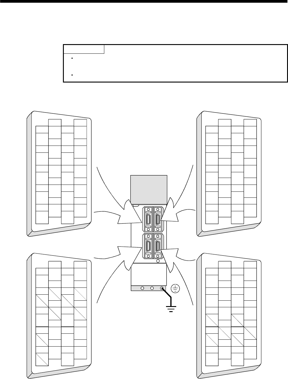
3 - 11
3. SIGNALS AND WIRING
3.3 I/O signals
3.3.1 Connectors and signal arrangements
POINT
The pin configurations of the connectors are as viewed from the cable
connector wiring section.
Refer to the next page for CN1A and CN1B signal assignment.
(1) MR-J2S-700A or less
1
2
3
5
4
6
7
9
8
10
11
12
13
14
15
16
17
18
19
20
RXD
MO1
TRE
LG
LG
RDP
SDP
TXD
MO2
P5
LG
LG
RDN
SDN
1
2
3
5
4
6
7
9
8
10
11
12
13
14
15
16
17
18
19
20
1
2
3
5
4
6
7
9
8
10
11
12
13
14
15
16
17
18
19
20
1
2
3
5
4
6
7
9
8
10
11
12
13
14
15
16
17
18
19
20
MD
LG
MDR
P5
LG
MRR
P5
LG
P5
BAT
MR
LG
MITSUBISHI
MELSERVO-J2
CN2 CN3
CN1A CN1B
The connector frames are
connected with the PE (earth)
terminal inside the servo amplifier.
3 - 12
3. SIGNALS AND WIRING
(2) MR-J2S-11KA or more
2
RXD
4
6
8
10
1
LG
3
5
7
TRE
9
12
TXD
14
16
18
20
11
LG
13
15
17
19
RDNRDP
SDP
P5
SDN
CN3
CON2
MITSUBISHI
CHARGE
2
LG
4
6
MD
8
10
1
LG
3
5
7
MR
9
12
LG
14
16
MDR
18
P5
20
11
LG
13
15
17
MRR
19
P5
P5
BAT
CN2
CN1A
CN1B
CN4
1
2
4
MO1
MO2
LG
Same as the one of the
MR-J2S-700A or less.
Same as the one of the
MR-J2S-700A or less.
The connector frames are
connected with the PE (earth)
terminal inside the servo amplifier.
For maker adjustment.
Keep this open.
3 - 13
3. SIGNALS AND WIRING
(3) CN1A and CN1B signal assignment
The signal assignment of connector changes with the control mode as indicated below;
For the pins which are given parameter No.s in the related parameter column, their signals can be
changed using those parameters.
(Note2)I/O Signals in control modes
Connector Pin No. (Note1)I/O P P/S S S/T T T/P
Related
parameter
1 LGLGLGLGLGLG
2 I NP NP/ /NP
3 I PP PP/ /PP
4 P15R P15R/P15R P15R P15R P15R P15R
5 O LZ LZ LZ LZ LZ LZ
6 O LA LA LA LA LA LA
7 O LB LB LB LB LB LB
8 I CR CR/SP1 SP1 SP1/SP1 SP1 SP1/CR No.43 to 48
9 COM COM COM COM COM COM
10 SG SG SG SG SG SG
11 OPC OPC/ /OPC
12 I NG NG/ /NG
13 I PG PG/ /PG
14O OPOPOPOPOPOP
15 O LZR LZR LZR LZR LZR LZR
16 O LAR LAR LAR LAR LAR LAR
17 O LBR LBR LBR LBR LBR LBR
18 O INP INP/SA SA SA/ /INP No.49
19O RDRDRDRDRDRDNo.49
CN1A
20 SG SG SG SG SG SG
1 LGLGLGLGLGLG
2I /VC VC VC/VLA VLA VLA/
3 VDD VDD VDD VDD VDD VDD
(Note 4)4 O DO1 DO1 DO1 DO1 DO1 DO1
5 I SON SON SON SON SON SON No.43 to 48
6 O TLC TLC TLC TLC/VLC VLC VLC/TLC No.49
7 I LOP SP2 LOP SP2 LOP No.43 to 48
8 I PC PC/ST1 ST1 ST1/RS2 RS2 RS2/PC No.43 to 48
9 I TL TL/ST2 ST2 ST2/RS1 RS1 RS1/TL No.43 to 48
10 SG SG SG SG SG SG
11 P15R P15R P15R P15R P15R P15R
12 I TLA (Note3)
TLA/TLA (Note3) TLA
(Note3)
TLA/TC
TC TC/TLA
13 COM COM COM COM COM COM
14 I RES RES RES RES RES RES No.43 to 48
15 I EMG EMG EMG EMG EMG EMG
16 I LSP LSP LSP LSP/ /LSP
17 I LSN LSN LSN LSN/ /LSN
18 O ALM ALM ALM ALM ALM ALM No.49
19 O ZSP ZSP ZSP ZSP ZSP ZSP No.1, 49
CN1B
20 SG SG SG SG SG SG
Note 1. I : Input signal, O: Output signal
2. P : Position control mode, S: Speed control mode, T: Torque control mode, P/S: Position/speed control change mode,
S/T: Speed/torque control change mode, T/P: Torque/position control change mode
3. By setting parameters No. 43 to 48 to make TL available, TLA can be used.
4. CN1B-4 and CN1A-18 output signals are the same. However, this pin may not be used when assigning alarm codes to
CN1A-18.

3 - 14
3. SIGNALS AND WIRING
(4) Symbols and signal names
Symbol Signal name Symbol Signal name
SON Servo-on VLC Limiting speed
LSP Forward rotation stroke end RD Ready
LSN Reverse rotation stroke end ZSP Zero speed
CR Clear INP In position
SP1 Speed selection 1 SA Speed reached
SP2 Speed selection 2 ALM Trouble
PC Proportion control WNG Warning
ST1 Forward rotation start BWNG Battery warning
ST2 Reverse rotation start OP Encoder Z-phase pulse (open collector)
TL Torque limit selection MBR Electromagnetic brake interlock
RES Reset LZ
EMG Emergency stop LZR Encoder Z-phase pulse
(differential line driver)
LOP Control change LA
VC Analog speed command LAR Encoder A-phase pulse
(differential line driver)
VLA Analog speed limit LB
TLA Analog torque limit LBR Encoder B-phase pulse
(differential line driver)
TC Analog torque command VDD I/F internal power supply
RS1 Forward rotation selection COM Digital I/F power supply input
RS2 Reverse rotation selection OPC Open collector power input
PP SG Digital I/F common
NP P15R 15VDC power supply
PG LG Control common
NG
Forward/reverse rotation pulse train
SD Shield
TLC Limiting torque
3 - 15
3. SIGNALS AND WIRING
3.3.2 Signal explanations
For the I/O interfaces (symbols in I/O division column in the table), refer to Section 3.6.2.
In the control mode field of the table
P : Position control mode, S: Speed control mode, T: Torque control mode
: Denotes that the signal may be used in the initial setting status.
: Denotes that the signal may be used by setting the corresponding parameter among parameters 43 to
49.
The pin No.s in the connector pin No. column are those in the initial status.
(1) Input signals
Control
mode
Signal Symbol
Connec-
tor pin
No.
Functions/Applications I/O
division PST
Servo-on SON CN1B
5Turn SON on to power on the base circuit and make the servo
amplifier ready to operate (servo-on).
Turn it off to shut off the base circuit and coast the servo motor
(servo off).
Set " 1" in parameter No. 41 to switch this signal on
(keep terminals connected) automatically in the servo
amplifier.
DI-1
Reset RES CN1B
14 Turn RES on for more than 50ms to reset the alarm.
Some alarms cannot be deactivated by the reset signal. Refer to
Section 10.2.
Turning RES on in an alarm-free status shuts off the base circuit.
The base circuit is not shut off when " 1 " is set in parameter
No. 51.
DI-1
To start operation, turn LSP/LSN on. Turn it off to bring the
motor to a sudden stop and make it servo-locked.
Set " 1" in parameter No. 22 to make a slow stop.
(Refer to Section 5.2.3.)
(Note) Input signals Operation
LSP LSN CCW
direction
CW
direction
11
Forward rotation
stroke end LSP CN1B
16
01
10
00
Note. 0: off
1: on
Set parameter No. 41 as indicated below to switch on the signals
(keep terminals connected) automatically in the servo amplifier:
Parameter No.41 Automatic ON
1 LSP
1 LSN
Reverse rotation
stroke end LSN CN1B
17
DI-1
3 - 16
3. SIGNALS AND WIRING
Control
mode
Signal Symbol
Connec-
tor pin
No.
Functions/Applications I/O
division PST
External torque
limit selection TL CN1B
9Turn TL off to make Internal torque limit 1 (parameter No. 28)
valid, or turn it on to make Analog torque limit (TLA) valid.
For details, refer to (5), Section 3.4.1.
DI-1
Internal
torque limit
selection
TL1 When using this signal, make it usable by making the setting of
parameter No. 43 to 48.
For details, refer to (5), Section 3.4.1.
DI-1
Used to start the servo motor in any of the following directions:
(Note) Input signals
ST2 ST1 Servo motor starting direction
Forward rotation
start ST1 CN1B
8
0 0 Stop (servo lock)
01 CCW
10 CW
1 1 Stop (servo lock)
Reverse rotation
start ST2 CN1B
9
Note. 0: off
1: on
If both ST1 and ST2 are switched on or off during operation, the
servo motor will be decelerated to a stop according to the
parameter No. 12 setting and servo-locked.
DI-1
Used to select any of the following servo motor torque generation
directions:
(Note) Input signals
RS2 RS1 Torque generation direction
Forward rotation
selection RS1 CN1B
9
0 0 Torque is not generated.
01
Forward rotation in driving mode /
reverse rotation in regenerative mode
10
Reverse rotation in driving mode /
forward rotation in regenerative mode
1 1 Torque is not generated.
Reverse rotation
selection RS2 CN1B
8
Note. 0: off
1: on
DI-1
3 - 17
3. SIGNALS AND WIRING
Control
mode
Signal Symbol Connec-
tor pin
No. Functions/Applications I/O
division PST
Speed selection 1 SP1 CN1A
8<Speed control mode>
Used to select the command speed for operation.
When using SP3, make it usable by making the setting of
parameter No. 43 to 48.
DI-1
(Note) Input
signals
Speed selection 2 SP2 CN1B
7Setting of
parameter
No. 43 to 48 SP3 SP2 SP1
Speed command DI-1
0 0 Analog speed command (VC)
01
Internal speed command 1
(parameter No. 8)
10
Internal speed command 2
(parameter No. 9)
When speed
selection
(SP3) is not
used
(initial status) 11
Internal speed command 3
(parameter No. 10)
0 0 0 Analog speed command (VC)
001
Internal speed command 1
(parameter No. 8)
010
Internal speed command 2
(parameter No. 9)
011
Internal speed command 3
(parameter No.10)
100
Internal speed command 4
(parameter No. 72)
101
Internal speed command 5
(parameter No. 73)
110
Internal speed command 6
(parameter No. 74)
When speed
selection
(SP3) is made
valid
111
Internal speed command 7
(parameter No. 75)
Note. 0: off
1: on
<Torque control mode>
Used to select the limit speed for operation.
When using SP3, make it usable by making the setting of
parameter No. 43 to 48.
(Note) Input
signals
Setting of
parameter
No. 43 to 48 SP3 SP2 SP1
Speed limit
0 0 Analog speed limit (VLA)
01
Internal speed command 1
(parameter No. 8)
10
Internal speed command 2
(parameter No. 9)
When speed
selection
(SP3) is not
used
(initial status) 11
Internal speed command 3
(parameter No. 10)
0 0 0 Analog speed limit (VLA)
001
Internal speed command 1
(parameter No. 8)
010
Internal speed command 2
(parameter No. 9)
011
Internal speed command 3
(parameter No.10)
100
Internal speed command 4
(parameter No. 72)
101
Internal speed command 5
(parameter No. 73)
110
Internal speed command 6
(parameter No. 74)
When speed
selection
(SP3) is made
valid
111
Internal speed command 7
(parameter No. 75)
Speed selection 3 SP3
Note. 0: off
1: on
DI-1
3 - 18
3. SIGNALS AND WIRING
Control
mode
Signal Symbol
Connec-
tor pin
No.
Functions/Applications I/O
division PST
Proportion
control PC CN1B
8Connect PC-SG to switch the speed amplifier from the
proportional integral type to the proportional type.
If the servo motor at a stop is rotated even one pulse due to any
external factor, it generates torque to compensate for a position
shift. When the servo motor shaft is to be locked mechanically
after positioning completion (stop), switching on the proportion
control (PC) upon positioning completion will suppress the
unnecessary torque generated to compensate for a position shift.
When the shaft is to be locked for a long time, switch on the
proportion control (PC) and torque control (TL) at the same time
to make the torque less than the rated by the analog torque limit.
DI-1
Emergency stop EMG CN1B
15 Turn EMG off (open EMG-common) to bring the motor to an
emergency stop state, in which the base circuit is shut off and the
dynamic brake is operated.
Turn EMG on (short EMG-common) in the emergency stop state
to reset that state.
DI-1
Clear CR CN1A
8Turn CR on to clear the position control counter droop pulses on
its leading edge. The pulse width should be 10ms or more.
When the parameter No. 42 setting is " 1 ", the pulses are
always cleared while CR is on.
DI-1
Electronic gear
selection 1 CM1 When using CM1 and CM2, make them usable by the setting of
parameters No. 43 to 48.
The combination of CM1 and CM2 gives you a choice of four
different electronic gear numerators set in the parameters.
CM1 and CM2 cannot be used in the absolute position detection
system.
DI-1
(Note) Input signals
CM2 CM1 Electronic gear molecule
00 Parameter No. 3
01 Parameter No. 69
10 Parameter No. 70
11 Parameter No. 71
Electronic gear
selection 2 CM2
Note. 0: off
1: on
DI-1
Gain changing CDP When using this signal, make it usable by the setting of
parameter No. 43 to 48.
Turn CDP on to change the load inertia moment ratio into the
parameter No. 61 setting and the gain values into the values
multiplied by the parameter No. 62 to 64 settings.
DI-1
3 - 19
3. SIGNALS AND WIRING
Control
mode
Signal Symbol
Connec-
tor pin
No.
Functions/Applications I/O
division PST
<Position/speed control change mode>
Used to select the control mode in the position/speed control
change mode.
(Note) LOP Control mode
0Position
1 Speed
Note. 0: off
1: on
<Speed/torque control change mode>
Used to select the control mode in the speed/torque control change
mode.
(Note) LOP Control mode
0 Speed
1Torque
Note. 0: off
1: on
<Torque/position control mode>
Used to select the control mode in the torque/position control
change mode.
(Note) LOP Control mode
0Torque
1Position
Control change LOP CN1B
7
Note. 0: off
1: on
DI-1 Refer to
Functions/
Appli-
cations.
Analog torque
limit TLA To use this signal in the speed control mode, set any of
parameters No. 43 to 48 to make TL available.
When the analog torque limit (TLA) is valid, torque is limited in
the full servo motor output torque range. Apply 0 to 10VDC
across TLA-LG. Connect the positive terminal of the power supply
to TLA. Maximum torque is generated at 10V. (Refer to (5) in
Section 3.4.1.) Resolution:10bit
Analog
input
Analog torque
command TC
CN1B
12
Used to control torque in the full servo motor output torque
range.
Apply 0 to 8VDC across TC-LG. Maximum torque is generated
at 8V. (Refer to (1) in Section 3.4.3.)
The torque at 8V input can be changed using parameter No. 26.
Analog
input
Analog speed
command VC Apply 0 to 10VDC across VC-LG. Speed set in parameter No. 25
is provided at 10V. (Refer to (1) in Section 3.4.2.)
Resolution:14bit or equivalent
Analog
input
Analog speed
limit VLA
CN1B
2
Apply 0 to 10VDC across VLA-LG. Speed set in parameter No.
25 is provided at 10V (Refer to (3) in Section 3.4.3.). Analog
input
Forward rotation
pulse train
Reverse rotation
pulse train
PP
NP
PG
NG
CN1A
3
CN1A
2
CN1A
13
CN1A
12
Used to enter a command pulse train.
In the open collector system (max. input frequency 200kpps):
Forward rotation pulse train across PP-SG
Reverse rotation pulse train across NP-SG
In the differential receiver system (max. input frequency
500kpps):
Forward rotation pulse train across PG-PP
Reverse rotation pulse train across NG-NP
The command pulse train form can be changed using
parameter No. 21.
DI-2
3 - 20
3. SIGNALS AND WIRING
(2) Output signals
Control
mode
Signal Symbol
Connec-
tor pin
No.
Functions/Applications I/O
division PST
Trouble ALM CN1B
18 ALM turns off when power is switched off or the protective circuit
is activated to shut off the base circuit.
Without alarm occurring, ALM turns on within about 1s after
power-on.
DO-1
Dynamic brake
interlock DB This signal can be used with the 11kW or more servo amplifier.
When using this signal, set " 1 " in parameter No. 1.
When the dynamic brake is operated, DB turns off. (Refer to
Section 13.1.4.)
DO-1
Ready RD CN1A
19 RD turns on when the servo is switched on and the servo
amplifier is ready to operate. DO-1
In position INP INP turns on when the number of droop pulses is in the preset in-
position range. The in-position range can be changed using
parameter No. 5.
When the in-position range is increased, INP-SG may be kept
connected during low-speed rotation.
DO-1
Speed reached SA
CN1A
18
SA turns off when servo on (SON) turns off or the servomotor
speed has not reached the preset speed with both forward rotation
start (ST1) and reverse rotation start (ST2) turned off. SA turns
on when the servomotor speed has nearly reached the preset
speed. When the preset speed is 20r/min or less, SA always turns
on.
DO-1
Limiting speed VLC VLC turns on when speed reaches the value limited using any of
the internal speed limits 1 to 7 (parameter No. 8 to 10, 72 to 75)
or the analog speed limit (VLA) in the torque control mode.
VLC turns off when servo on (SON) turns off.
DO-1
Limiting torque TLC
CN1B
6
TLC turns on when the torque generated reaches the value set to
the internal torque limit 1 (parameter No. 28) or analog torque
limit (TLA).
DO-1
Zero speed ZSP CN1B
19 ZSP turns on when the servo motor speed is zero speed (50r/min)
or less. Zero speed can be changed using parameter No. 24. DO-1
Electromagnetic
brake interlock MBR CN1B
19 Set " 1 " in parameter No. 1 to use this parameter. Note that
ZSP will be unusable.
MBR turns off when the servo is switched off or an alarm occurs.
DO-1
Warning WNG To use this signal, assign the connector pin for output using
parameter No.49. The old signal before assignment will be
unusable.
When warning has occurred, WNG turns on.
When there is no warning, WNG turns off within about 1s after
power-on.
DO-1
Battery warning BWNG To use this signal, assign the connector pin for output using
parameter No.49. The old signal before assignment will be
unusable.
BWNG turns on when battery cable breakage warning (AL. 92) or
battery warning (AL. 9F) has occurred.
When there is no battery warning, BWNG turns off within about
1s after power-on.
DO-1
3 - 21
3. SIGNALS AND WIRING
Control
mode
Signal Symbol
Connec-
tor pin
No.
Functions/Applications I/O
division PST
To use this signal, set " 1 " in parameter No.49.
This signal is output when an alarm occurs. When there is no
alarm, respective ordinary signals (RD, INP, SA, ZSP) are output.
Alarm codes and alarm names are listed below:
(Note) Alarm code
CN1B
19 Pin
CN1A
18 Pin
CN1A
19 Pin
Alarm
display Name
88888 Watchdog
AL.12 Memory error 1
AL.13 Clock error
AL.15 Memory error 2
AL.17 Board error
AL.19 Memory error 3
AL.37 Parameter error
AL.8A Serial communication
timeout
000
AL.8E Serial communication error
AL.30 Regenerative error
001
AL.33 Overvoltage
010AL.10Undervoltage
AL.45 Main circuit device
AL.46 Servo motor overheat
AL.50 Overload 1
011
AL.51 Overload 2
AL.24 Main circuit error
100
AL.32 Overcurrent
AL.31 Overspeed
AL.35 Command pulse frequency
alarm
101
AL.52 Error excessive
AL.16 Encoder error 1
AL.1A Monitor combination error
AL.20 Encoder error 2
110
AL.25 Absolute position erase
Alarm code ACD 0
ACD 1
ACD 2
CN1A
19
CN1A
18
CN1B
19
Note. 0: off
1: on
DO-1
3 - 22
3. SIGNALS AND WIRING
Connector pin No. Control
mode
Signal Symbol 7kW or
less
11kW or
more
Functions/Applications I/O
division PST
Encoder Z-phase
pulse
(Open collector)
OP CN1A
14 CN1A
14 Outputs the zero-point signal of the encoder. One pulse is
output per servo motor revolution. OP turns on when the
zero-point position is reached. (Negative logic)
The minimum pulse width is about 400 s. For home
position return using this pulse, set the creep speed to
100r/min. or less.
DO-2
Encoder A-phase
pulse
(Differential line
driver)
LA
LAR
CN1A
6
CN1A
16
CN1A
6
CN1A
16
Encoder B-phase
pulse
(Differential line
driver)
LB
LBR
CN1A
7
CN1A
17
CN1A
7
CN1A
17
Outputs pulses per servo motor revolution set in
parameter No. 27 in the differential line driver system.
In CCW rotation of the servo motor, the encoder B-phase
pulse lags the encoder A-phase pulse by a phase angle of
/2.
The relationships between rotation direction and phase
difference of the A- and B-phase pulses can be changed
using parameter No. 54.
DO-2
Encoder Z-phase
pulse
(Differential line
driver)
LZ
LZR
CN1A
5
CN1A
15
CN1A
5
CN1A
15
The same signal as OP is output in the differential line
driver system. DO-2
Analog monitor 1 MO1 CN3
4CN4
1Used to output the data set in parameter No.17 to across
MO1-LG in terms of voltage. Resolution 10 bits Analog
output
Analog monitor 2 MO2 CN3
14 CN4
2Used to output the data set in parameter No.17 to across
MO2-LG in terms of voltage. Resolution 10 bits Analog
output
(3) Communication
POINT
Refer to Chapter 14 for the communication function.
Control
mode
Signal Symbol
Connec-
tor pin
No.
Functions/Applications I/O
division PST
RS-422 I/F SDP
SDN
RDP
RDN
CN3
9
CN3
19
CN3
5
CN3
15
RS-422 and RS-232C functions cannot be used together.
Choose either one in parameter No. 16.
RS-422
termination TRE CN3
10 Termination resistor connection terminal of RS-422 interface.
When the servo amplifier is the termination axis, connect this
terminal to RDN (CN3-15).
RS-232C I/F RXD
TXD
CN3
2
CN3
12
RS-422 and RS-232C functions cannot be used together.
Choose either one in parameter No. 16.
3 - 23
3. SIGNALS AND WIRING
(4) Power supply
Connector pin No. Control
mode
Signal Symbol 7kW or
less
11kW or
more
Functions/Applications I/O division
PST
I/F internal
power supply VDD CN1B
3CN1B
3Used to output 24V 10% to across VDD-SG.
When using this power supply for digital interface,
connect it with COM.
Permissible current : 80mA
Digital I/F power
supply input COM CN1A
9
CN1B
13
CN1A
9
CN1B
13
Used to input 24VDC for input interface.
Connect the positive terminal of the 24VDC external
power supply.
24VDC 10%
Open collector
power input OPC CN1A
11 CN1A
11 When inputting a pulse train in the open collector
system, supply this terminal with the positive ( ) power
of 24VDC.
Digital I/F
common SG CN1A
10
20
CN1B
10
20
CN1A
10
20
CN1B
10
20
Common terminal for input signals such as SON and
EMG. Pins are connected internally.
Separated from LG.
15VDC power
supply P15R CN1A
4
CN1B
11
CN1A
4
CN1B
11
Outputs 15VDC to across P15R-LG. Available as power
for TC, TLA, VC, VLA.
Permissible current: 30mA
Control common LG CN1A
1
CN1B
1
CN3
1, 11
3, 13
CN1A
1
CN1B
1
CN3
1, 11
3, 13
CN4
4
Common terminal for TLA, TC, VC, VLA, FPA, FPB, OP
,MO1, MO2 and P15R.
Pins are connected internally.
Shield SD Plate Plate Connect the external conductor of the shield cable.
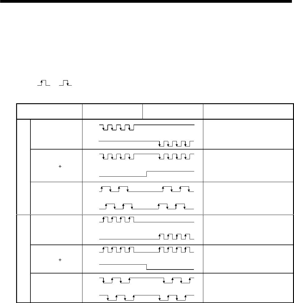
3 - 24
3. SIGNALS AND WIRING
3.4 Detailed description of the signals
3.4.1 Position control mode
(1) Pulse train input
(a) Input pulse waveform selection
Command pulses may be input in any of three different forms, for which positive or negative logic
can be chosen. Set the command pulse train form in parameter No. 21.
Arrow or in the table indicates the timing of importing a pulse train.
A- and B-phase pulse trains are imported after they have been multiplied by 4.
Pulse train form Forward rotation
command
Reverse rotation
command
Parameter No. 21
(Command pulse train)
Forward rotation
pulse train
Reverse rotation
pulse train
PP
NP 0010
Pulse train sign
PP
NP LH
0011
Negative logic
A-phase pulse train
B-phase pulse train
PP
NP
0012
Forward rotation
pulse train
Reverse rotation
pulse train
PP
NP
0000
Pulse train sign PP
NP HL
0001
Positive logic
A-phase pulse train
B-phase pulse train
PP
NP 0002
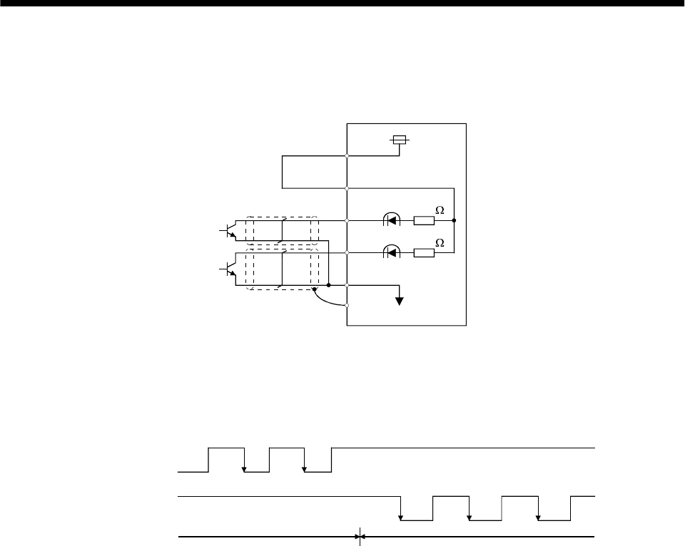
3 - 25
3. SIGNALS AND WIRING
(b) Connections and waveforms
1) Open collector system
Connect as shown below:
Approx.
1.2k
Approx.
1.2k
SG
SD
NP
PP
OPC
VDD
Servo amplifier
The explanation assumes that the input waveform has been set to the negative logic and forward
and reverse rotation pulse trains (parameter No.21 has been set to 0010). The waveforms in the
table in (a), (1) of this section are voltage waveforms of PP and NP based on SG. Their
relationships with transistor ON/OFF are as follows:
(ON)(OFF)
(ON) (OFF) (ON) (OFF) (ON)
(OFF)
Forward rotation
pulse train
(transistor)
Reverse rotation
pulse train
(transistor)
(ON)(OFF)
Forward rotation command Reverse rotation command
(OFF)
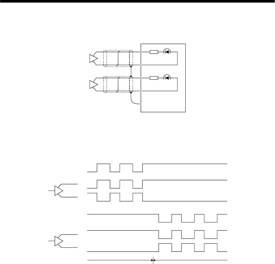
3 - 26
3. SIGNALS AND WIRING
2) Differential line driver system
Connect as shown below:
PP
NP
Servo amplifier
PG
NG
SD
The explanation assumes that the input waveform has been set to the negative logic and forward
and reverse rotation pulse trains (parameter No.21 has been set to 0010).
For the differential line driver, the waveforms in the table in (a), (1) of this section are as follows.
The waveforms of PP, PG, NP and NG are based on that of the ground of the differential line
driver.
PP
PG
NP
NG
Forward rotation
pulse train
Reverse rotation
pulse train
Forward rotation command Reverse rotation command
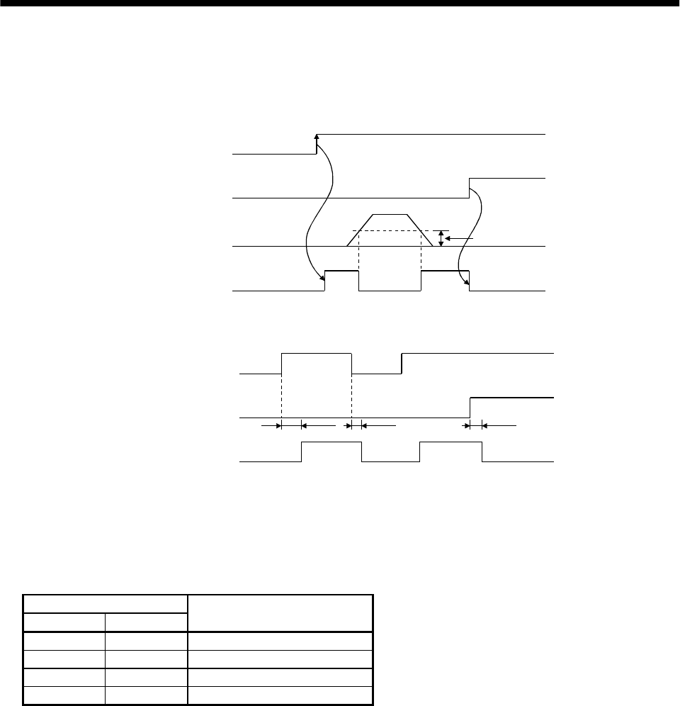
3 - 27
3. SIGNALS AND WIRING
(2) In-position (INP)
PF-SG are connected when the number of droop pulses in the deviation counter falls within the preset
in-position range (parameter No. 5). INP-SG may remain connected when low-speed operation is
performed with a large value set as the in-position range.
Servo-on (SON)
Alarm
Droop pulses
In position (INP)
ON
OFF
Yes
No
In-position range
ON
OFF
(3) Ready (RD)
Servo-on (SON)
Alarm
Ready (RD)
ON
OFF
Yes
No
80ms or less 10ms or less 10ms or less
ON
OFF
(4) Electronic gear switching
The combination of CM1 and CM2 gives you a choice of four different electronic gear numerators set in
the parameters.
As soon as CM1/CM2 is turned ON or OFF, the molecule of the electronic gear changes. Therefore, if
any shock occurs at this change, use position smoothing (parameter No. 7) to relieve shock.
(Note) External input signal
CM2 CM1 Electronic gear molecule
00 Parameter No. 3
01 Parameter No. 69
10 Parameter No. 70
11 Parameter No. 71
Note. 0: off
1: on
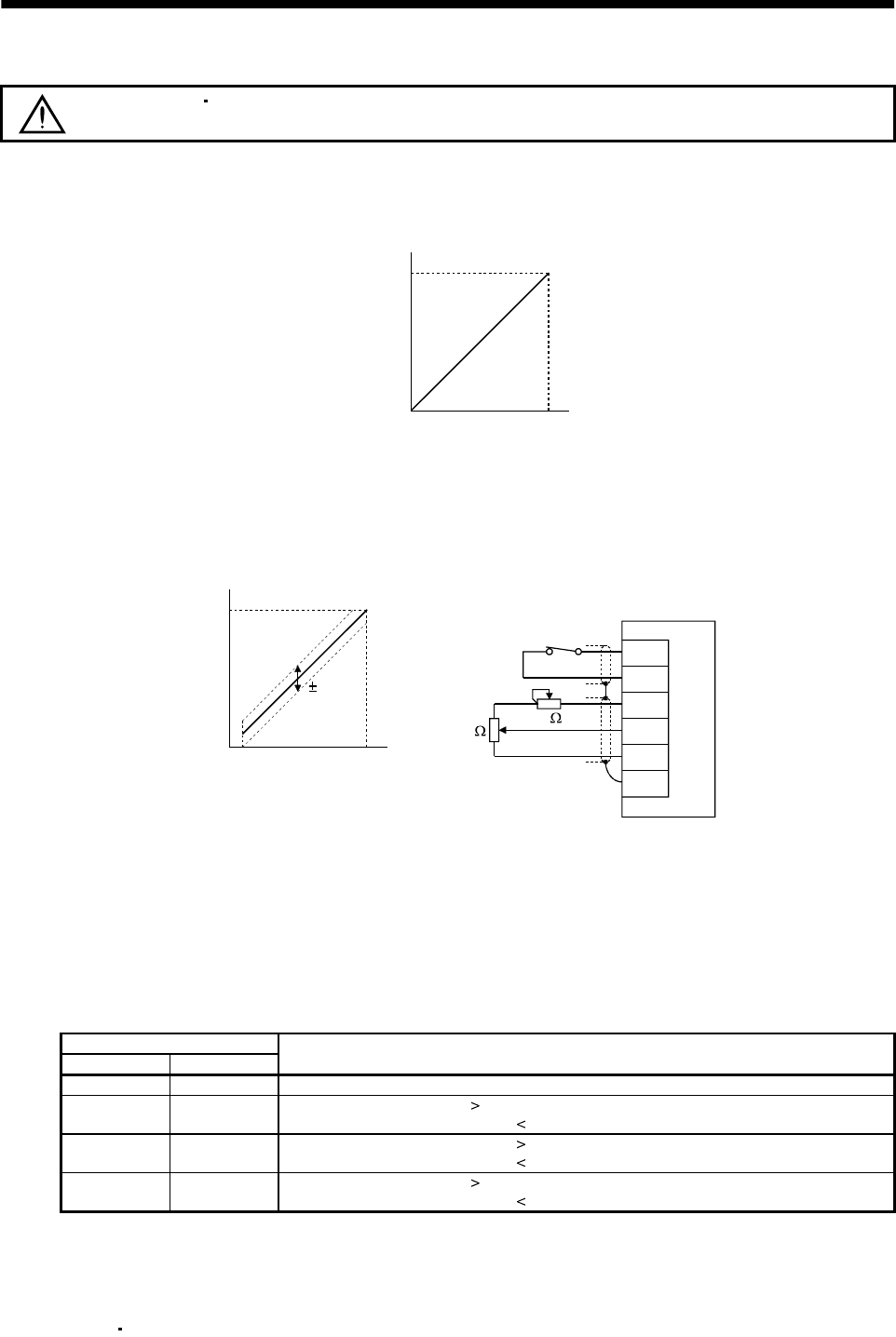
3 - 28
3. SIGNALS AND WIRING
(5) Torque limit
CAUTION If the torque limit is canceled during servo lock, the servomotor may suddenly
rotate according to position deviation in respect to the command position.
(a) Torque limit and torque
By setting parameter No. 28 (internal torque limit 1), torque is always limited to the maximum
value during operation. A relationship between the limit value and servo motor torque is shown
below.
00 100
Max. torque
torque
Torque limit value [%]
A relationship between the applied voltage of the analog torque limit (TLA) and the torque limit
value of the servo motor is shown below. Torque limit values will vary about 5% relative to the
voltage depending on products.
At the voltage of less than 0.05V, torque may vary as it may not be limited sufficiently. Therefore,
use this function at the voltage of 0.05V or more.
2k 2k
Servo amplifier
Japan resistor
RRS10 or equivalent
TL
SG
P15R
TLA
LG
SD
100
0
010
5%
0.05
Torque limit value [%]
TLA application voltage vs.
torque limit value
TLA application voltage [V]
(b) Torque limit value selection
Choose the torque limit made valid by the internal torque limit value 1 (parameter No. 28) using
the external torque limit selection (TL) or the torque limit made valid by the analog torque limit
(TLA) as indicated below.
When internal torque limit selection (TL1) is made usable by parameter No. 43 to 48, internal
torque limit 2 (parameter No. 76) can be selected. However, if the parameter No. 28 value is less
than the limit value selected by TL/TL1, the parameter No. 28 value is made valid.
(Note) External input signals
TL1 TL Torque limit value made valid
0 0 Internal torque limit value 1 (parameter No. 28)
01 TLA Parameter No. 28: Parameter No. 28
TLA Parameter No. 28: TLA
10 Parameter No. 76 Parameter No. 28: Parameter No. 28
Parameter No. 76 Parameter No. 28: Parameter No. 76
11 TLA Parameter No. 76: Parameter No. 76
TLA Parameter No. 76: TLA
Note. 0: off
1: on
(c) Limiting torque (TLC)
TLC turns on when the servo motor torque reaches the torque limited using the internal torque
limit 1 2 or analog torque limit.
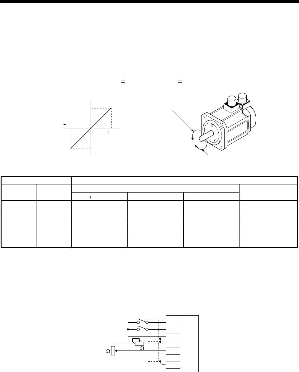
3 - 29
3. SIGNALS AND WIRING
3.4.2 Speed control mode
(1) Speed setting
(a) Speed command and speed
The servo motor is run at the speeds set in the parameters or at the speed set in the applied
voltage of the analog speed command (VC). A relationship between the analog speed command
(VC) applied voltage and the servo motor speed is shown below:
The maximum speed is achieved at 10V. The speed at 10V can be changed using parameter No.
25.
10
010
Rated speed [r/min]
Speed [r/min]
CW direction VC applied voltage [V]
CCW direction
Rated speed
Forward rotation (CCW)
Reverse rotation (CW)
The following table indicates the rotation direction according to forward rotation start (ST1) and
reverse rotation start (ST2) combination:
(Note 1) External input signals (Note 2) Rotation direction
Analog speed command (VC)
ST2 ST1 Polarity 0V Polarity
Internal speed
commands
00 Stop
(Servo lock) Stop
(Servo lock) Stop
(Servo lock) Stop
(Servo lock)
0 1 CCW CW CCW
10 CW Stop
(No servo lock) CCW CW
11 Stop
(Servo lock) Stop
(Servo lock) Stop
(Servo lock) Stop
(Servo lock)
Note 1. 0: off
1: on
2. If the torque limit is canceled during servo lock, the servomotor may suddenly rotate according to position deviation in
respect to the command position.
The forward rotation start (ST1) and reverse rotation start (ST2) can be assigned to any pins of
the connector CN1A, CN1B using parameters No. 43 to 48.
Generally, make connection as shown below:
ST1
ST2
SG
P15R
VC
LG
SD
2k
2k
Servo amplifier
Japan resistor
RRS10 or equivalent
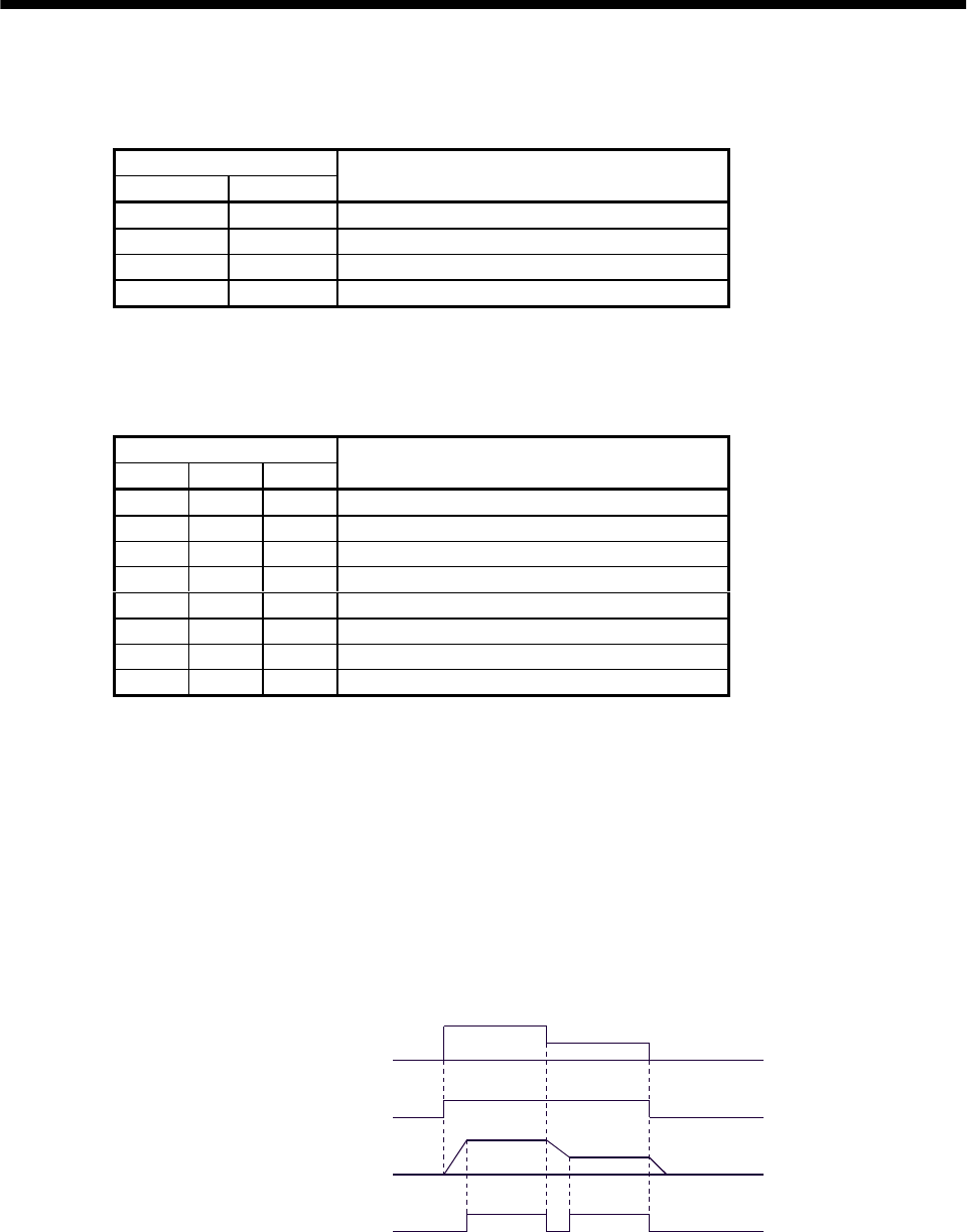
3 - 30
3. SIGNALS AND WIRING
(b) Speed selection 1 (SP1), speed selection 2 (SP2) and speed command value
Choose any of the speed settings made by the internal speed commands 1 to 3 using speed selection
1 (SP1) and speed selection 2 (SP2) or the speed setting made by the analog speed command (VC).
(Note) External input signals
SP2 SP1 Speed command value
0 0 Analog speed command (VC)
0 1 Internal speed command 1 (parameter No. 8)
1 0 Internal speed command 2 (parameter No. 9)
1 1 Internal speed command 3 (parameter No. 10)
Note. 0: off
1: on
By making speed selection 3 (SP3) usable by setting of parameter No. 43 to 48, you can choose
the speed command values of analog speed command (VC) and internal speed commands 1 to 7.
(Note) External input signals
SP3 SP2 SP1 Speed command value
0 0 0 Analog speed command (VC)
0 0 1 Internal speed command 1 (parameter No. 8)
0 1 0 Internal speed command 2 (parameter No. 9)
0 1 1 Internal speed command 3 (parameter No. 10)
1 0 0 Internal speed command 4 (parameter No. 72)
1 0 1 Internal speed command 5 (parameter No. 73)
1 1 0 Internal speed command 6 (parameter No. 74)
1 1 1 Internal speed command 7 (parameter No. 75)
Note. 0: off
1: on
The speed may be changed during rotation. In this case, the values set in parameters No. 11 and
12 are used for acceleration/deceleration.
When the speed has been specified under any internal speed command, it does not vary due to the
ambient temperature.
(2) Speed reached (SA)
SA turns on when the servo motor speed has nearly reached the speed set to the internal speed
command or analog speed command.
ON
OFF
ON
OFF
Set speed selection Internal speed
command 1
Internal speed
command 2
Start (ST1,ST2)
Servo motor speed
Speed reached (SA)
(3) Torque limit
As in Section 3.4.1 (5).
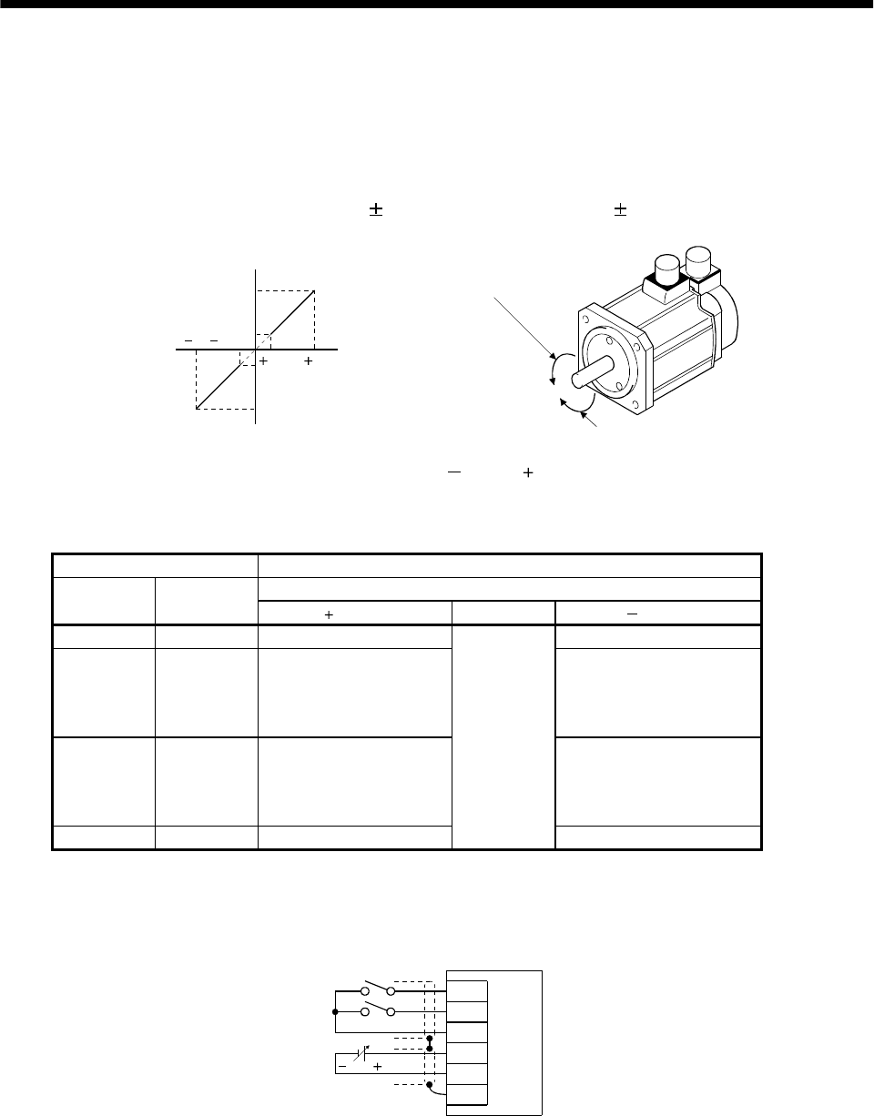
3 - 31
3. SIGNALS AND WIRING
3.4.3 Torque control mode
(1) Torque control
(a) Torque command and torque
A relationship between the applied voltage of the analog torque command (TC) and the torque by
the servo motor is shown below.
The maximum torque is generated at 8V. Note that the torque at 8V input can be changed with
parameter No. 26.
8
0.05 8
0.05
Max. torque
Generated torque
CCW direction
CW direction Max. torque (Note)
TC applied voltage [V]
Forward rotation (CCW)
Reverse rotation (CW)
Generated torque limit values will vary about 5% relative to the voltage depending on products.
Also the torque may vary if the voltage is low ( 0.05 to 0.05V) and the actual speed is close to
the limit value. In such a case, increase the speed limit value.
The following table indicates the torque generation directions determined by the forward rotation
selection (RS1) and reverse rotation selection (RS2) when the analog torque command (TC) is used.
(Note) External input signals Rotation direction
Torque control command (TC)
RS2 RS1 Polarity 0V Polarity
0 0 Torque is not generated. Torque is not generated.
01
CCW (reverse rotation in
driving mode/forward
rotation in regenerative
mode)
CW (forward rotation in
driving mode/reverse
rotation in regenerative
mode)
10
CW (forward rotation in
driving mode/reverse
rotation in regenerative
mode)
CCW (reverse rotation in
driving mode/forward
rotation in regenerative
mode)
1 1 Torque is not generated.
Torque is not
generated.
Torque is not generated.
Note. 0: off
1: on
Generally, make connection as shown below:
RS1
RS2
SG
TC
LG
SD
8 to 8V
Servo amplifier
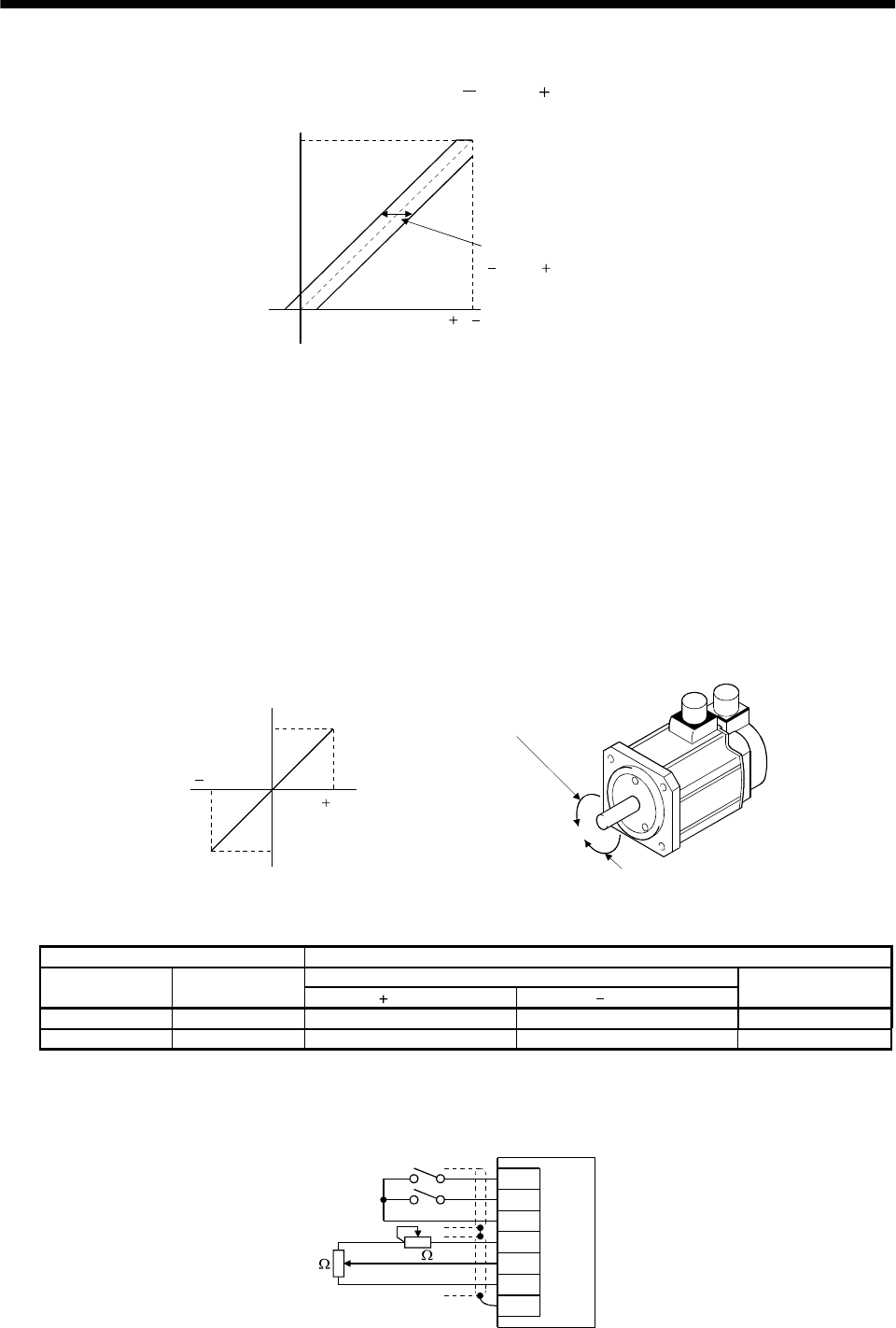
3 - 32
3. SIGNALS AND WIRING
(b) Analog torque command offset
Using parameter No. 30, the offset voltage of 999 to 999mV can be added to the TC applied
voltage as shown below.
08( 8)
Max. torque
Generated torque
TC applied voltage [V]
Parameter No.30 offset rang
e
999 to 999mV
(2) Torque limit
By setting parameter No. 28 (internal torque limit 1), torque is always limited to the maximum value
during operation. A relationship between limit value and servo motor torque is as in (5) in section
3.4.1. Note that the analog torque limit (TLA) is unavailable.
(3) Speed limit
(a) Speed limit value and speed
The speed is limited to the values set in parameters No. 8 to 10, 72 to 75 (internal speed limits 1 to
7) or the value set in the applied voltage of the analog speed limit (VLA).
A relationship between the analog speed limit (VLA) applied voltage and the servo motor speed is
shown below.
When the servo motor speed reaches the speed limit value, torque control may become unstable.
Make the set value more than 100r/min greater than the desired speed limit value.
10
010
Rated speed
Speed [r/min] CCW direction
CW direction VLA applied voltage [V]
Forward rotation (CCW)
Reverse rotation (CW)
Rated speed
The following table indicates the limit direction according to forward rotation selection (RS1) and
reverse rotation selection (RS2) combination:
(Note) External input signals Speed limit direction
Analog speed limit (VLA)
RS1 RS2 Polarity Polarity
Internal speed
commands
1 0 CCW CW CCW
0 1 CW CCW CW
Note. 0: off
1: on
Generally, make connection as shown below:
SP1
SP2
SG
P15R
VC
LG
SD
2k
2k
Servo amplifier
Japan resistor
RRS10 or equivalent

3 - 33
3. SIGNALS AND WIRING
(b) Speed selection 1(SP1)/speed selection 2(SP2)/speed selection 3(SP3) and speed limit values
Choose any of the speed settings made by the internal speed limits 1 to 7 using speed selection
1(SP1), speed selection 2(SP2) and speed selection 3(SP3) or the speed setting made by the speed
limit command (VLA), as indicated below.
(Note) Input signals
Setting of parameter
No. 43 to 48 SP3 SP2 SP1 Speed limit value
0 0 Analog speed limit (VLA)
0 1 Internal speed limit 1 (parameter No. 8)
1 0 Internal speed limit 2 (parameter No. 9)
When speed selection
(SP3) is not used
(initial status) 1 1 Internal speed limit 3 (parameter No. 10)
0 0 0 Analog speed limit (VLA)
0 0 1 Internal speed limit 1 (parameter No. 8)
0 1 0 Internal speed limit 2 (parameter No. 9)
0 1 1 Internal speed limit 3 (parameter No. 10)
1 0 0 Internal speed limit 4 (parameter No. 72)
1 0 1 Internal speed limit 5 (parameter No. 73)
1 1 0 Internal speed limit 6 (parameter No. 74)
When speed selection
(SP3) is made valid
1 1 1 Internal speed limit 7 (parameter No. 75)
Note. 0: off
1: on
When the internal speed limits 1 to 7 are used to command the speed, the speed does not vary
with the ambient temperature.
(c) Limiting speed (VLC)
VLC turns on when the servo motor speed reaches the speed limited using any of the internal
speed limits 1 to 7 or the analog speed limit (VLA).
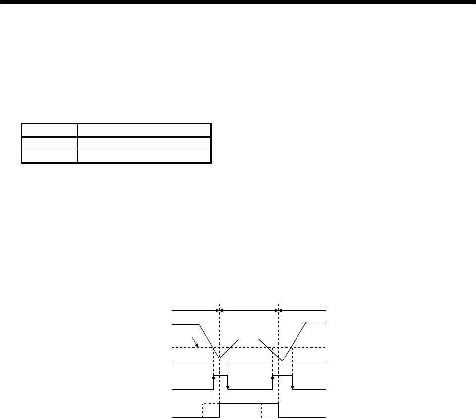
3 - 34
3. SIGNALS AND WIRING
3.4.4 Position/speed control change mode
Set "0001" in parameter No. 0 to switch to the position/speed control change mode. This function is not
available in the absolute position detection system.
(1) Control change (LOP)
Use control change (LOP) to switch between the position control mode and the speed control mode
from an external contact. Relationships between LOP and control modes are indicated below:
(Note) LOP Servo control mode
0 Position control mode
1 Speed control mode
Note. 0: off
1: on
The control mode may be changed in the zero-speed status. To ensure safety, change control after the
servo motor has stopped. When position control mode is changed to speed control mode, droop pulses are
reset.
If the signal has been switched on-off at the speed higher than the zero speed and the speed is then
reduced to the zero speed or less, the control mode cannot be changed. A change timing chart is shown
below:
ON
OFF
ON
OFF
Position
control mode
Speed
control mode
Servo motor speed
Zero speed (ZSP)
Control change (LOP)
Zero speed
level
(Note)
Note: When ZSP is not on, control cannot be changed if LOP is switched on-off.
If ZSP switches on after that, control cannot not be changed.
(Note)
Position
control mode
(2) Torque limit in position control mode
As in Section 3.4.1 (5).
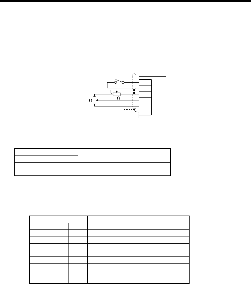
3 - 35
3. SIGNALS AND WIRING
(3) Speed setting in speed control mode
(a) Speed command and speed
The servo motor is run at the speed set in parameter No. 8 (internal speed command 1) or at the
speed set in the applied voltage of the analog speed command (VC). A relationship between analog
speed command (VC) applied voltage and servo motor speed and the rotation directions determined
by the forward rotation start (ST1) and reverse rotation start (ST2) are as in (a), (1) in section
3.4.2.
Generally, make connection as shown below:
Japan resistor
RRS10 or equivalent
SP1
SG
P15R
VC
LG
SD
Servo amplifier
2
k2k
(b) Speed selection 1 (SP1) and speed command value
Use speed selection 1 (SP1) to select between the speed set by the internal speed command 1 and
the speed set by the analog speed command (VC) as indicated in the following table:
(Note) External input signals
SP1 Speed command value
0 Analog speed command (VC)
1 Internal speed command 1 (parameter No. 8)
Note. 0: off
1: on
By making speed selection 2 (SP2) speed selection 3 (SP3) usable by setting of parameter No. 43
to 48, you can choose the speed command values of analog speed command (VC) and internal
speed commands 1 to 7.
(Note) External input signals
SP3 SP2 SP1 Speed command value
0 0 0 Analog speed command (VC)
0 0 1 Internal speed command 1 (parameter No. 8)
0 1 0 Internal speed command 2 (parameter No. 9)
0 1 1 Internal speed command 3 (parameter No. 10)
1 0 0 Internal speed command 4 (parameter No. 72)
1 0 1 Internal speed command 5 (parameter No. 73)
1 1 0 Internal speed command 6 (parameter No. 74)
1 1 1 Internal speed command 7 (parameter No. 75)
Note. 0: off
1: on
The speed may also be changed during rotation. In this case, it is increased or decreased according
to the value set in parameter No. 11 or 12.
When the internal speed command 1 is used to command the speed, the speed does not vary with
the ambient temperature.
(c) Speed reached (SA)
As in Section 3.4.2 (2).
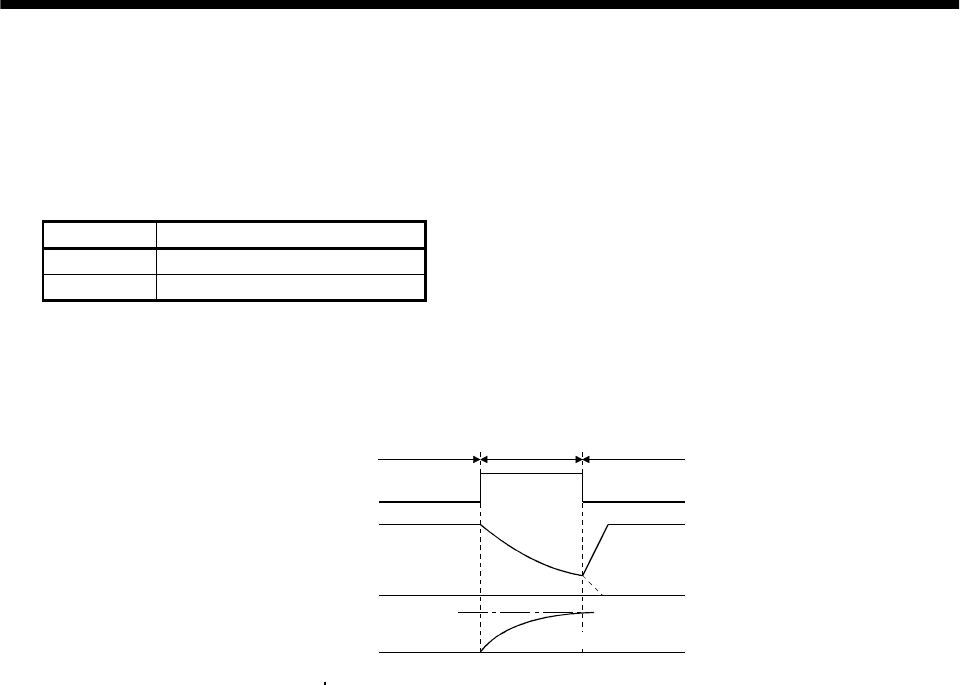
3 - 36
3. SIGNALS AND WIRING
3.4.5 Speed/torque control change mode
Set "0003" in parameter No. 0 to switch to the speed/torque control change mode.
(1) Control change (LOP)
Use control change (LOP) to switch between the speed control mode and the torque control mode from
an external contact. Relationships between LOP and control modes are indicated below:
(Note) LOP Servo control mode
0 Speed control mode
1 Torque control mode
Note. 0: off
1: on
The control mode may be changed at any time. A change timing chart is shown below:
Note: When the start (ST1 ST2) is switched off as soon as the mode is changed to speed control,
the servo motor comes to a stop according to the deceleration time constant.
10V
0
ON
OFF
Torque
control mode
Servo motor speed
Control change (LOP)
(Note)
Speed
control mode
Speed
control mode
Analog torque
command (TC)
Load torque
Forward rotation in driving mode
(2) Speed setting in speed control mode
As in Section 3.4.2 (1).
(3) Torque limit in speed control mode
As in Section 3.4.1 (5).
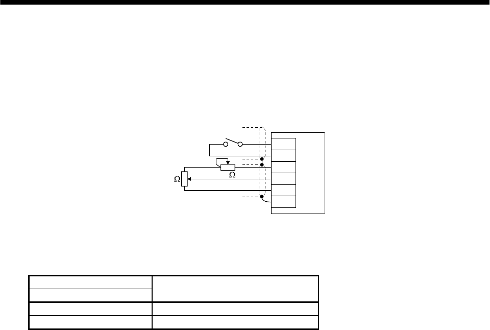
3 - 37
3. SIGNALS AND WIRING
(4) Speed limit in torque control mode
(a) Speed limit value and speed
The speed is limited to the limit value set in parameter No. 8 (internal speed limit 1) or the value
set in the applied voltage of the analog speed limit (VLA). A relationship between the analog speed
limit (VLA) applied voltage and the servo motor speed is as in (a), (3) in section 3.4.3.
Generally, make connection as shown below:
Japan resistor
RRS10 or equivalent
SP1
SG
P15R
VLA
LG
SD
Servo amplifie
r
2k 2k
(b) Speed selection 1 (SP1) and speed limit value
Use speed selection 1 (SP1) to select between the speed set by the internal speed command 1 and
the speed set by the analog speed limit (VLA) as indicated in the following table:
(Note) External input signals
SP1 Speed command value
0 Analog speed limit (VLA)
1 Internal speed limit 1 (parameter No. 8)
Note. 0: off
1: on
When the internal speed limit 1 is used to command the speed, the speed does not vary with the
ambient temperature.
(c) Limiting speed (VLC)
As in (c), (3) in section 3.4.3.
(5) Torque control in torque control mode
As in Section 3.4.3 (1).
(6) Torque limit in torque control mode
As in Section 3.4.3 (2).
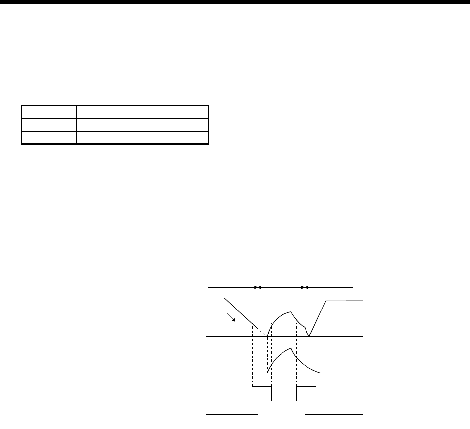
3 - 38
3. SIGNALS AND WIRING
3.4.6 Torque/position control change mode
Set "0005" in parameter No. 0 to switch to the torque/position control change mode.
(1) Control change (LOP)
Use control change (LOP) to switch between the torque control mode and the position control mode
from an external contact. Relationships between LOP and control modes are indicated below:
(Note) LOP Servo control mode
0 Torque control mode
1 Position control mode
Note. 0: off
1: on
The control mode may be changed in the zero-speed status.
To ensure safety, change control after the servo motor has stopped. When position control mode is
changed to torque control mode, droop pulses are reset.
If the signal has been switched on-off at the speed higher than the zero speed and the speed is then
reduced to the zero speed or less, the control mode cannot be changed. A change timing chart is shown
below:
0V
10V
ON
OFF
ON
OFF
Servo motor speed
Zero speed (ZSP)
Control change (LOP)
Zero speed
level
Analog torque
command (TLA)
Speed
control mode Torque
control mode Speed
control mode
(2) Speed limit in torque control mode
As in Section 3.4.3 (3).
(3) Torque control in torque control mode
As in Section 3.4.3 (1).
(4) Torque limit in torque control mode
As in Section 3.4.3 (2).
(5) Torque limit in position control mode
As in Section 3.4.1 (5).
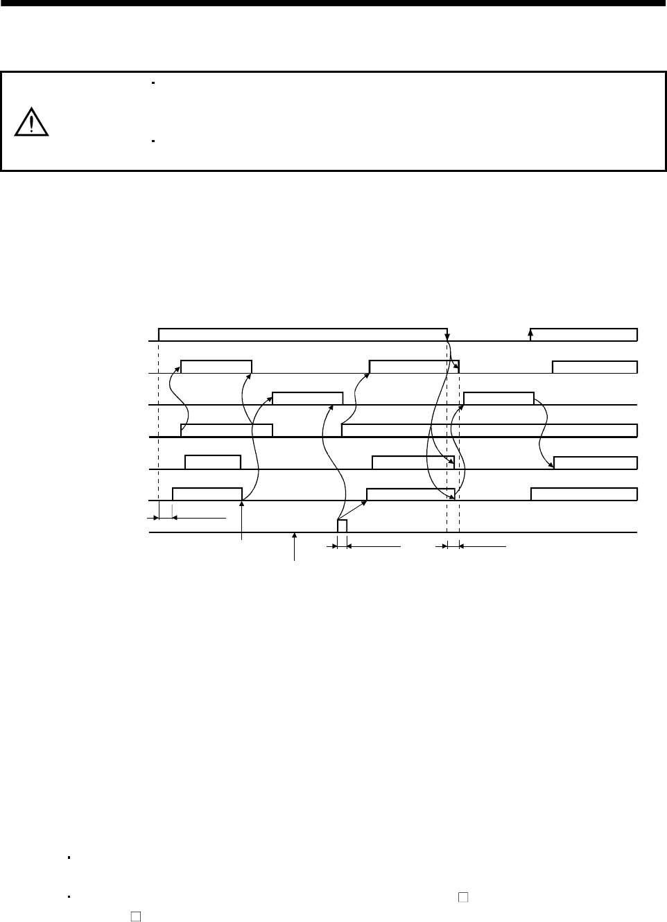
3 - 39
3. SIGNALS AND WIRING
3.5 Alarm occurrence timing chart
CAUTION
When an alarm has occurred, remove its cause, make sure that the operation
signal is not being input, ensure safety, and reset the alarm before restarting
operation.
As soon as an alarm occurs, turn off Servo-on (SON) and power off the main
circuit.
When an alarm occurs in the servo amplifier, the base circuit is shut off and the servo motor is coated to a
stop. Switch off the main circuit power supply in the external sequence. To reset the alarm, switch the
control circuit power supply from off to on, press the "SET" button on the current alarm screen, or turn
the reset (RES) from off to on. However, the alarm cannot be reset unless its cause is removed.
ON
OFF
ON
OFF
ON
OFF
ON
OFF
ON
OFF
ON
OFF
1s
Brake operation
50ms or more 60ms or more
Alarm occurs.
Remove cause of trouble.
Brake operation
Power off Power on
Valid
Invalid
Main circuit
control circuit
power supply
Base circuit
Dynamic brake
Servo-on
(SON)
Reset
(RES)
Ready
(RD)
Trouble
(ALM)
(Note)
Note. Shut off the main circuit power as soon as an alarm occurs.
about
(1) Overcurrent, overload 1 or overload 2
If operation is repeated by switching control circuit power off, then on to reset the overcurrent
(AL.32), overload 1 (AL.50) or overload 2 (AL.51) alarm after its occurrence, without removing
its cause, the servo amplifier and servo motor may become faulty due to temperature rise.
Securely remove the cause of the alarm and also allow about 30 minutes for cooling before
resuming operation.
(2) Regenerative alarm
If operation is repeated by switching control circuit power off, then on to reset the regenerative
(AL.30) alarm after its occurrence, the external regenerative brake resistor will generate heat,
resulting in an accident.
(3) Instantaneous power failure
Undervoltage (AL.10) occurs when the input power is in either of the following statuses.
A power failure of the control circuit power supply continues for 60ms or longer and the
control circuit is not completely off.
The bus voltage dropped to 200VDC or less for the MR-J2S- A, or to 158VDC or less for the
MR-J2S- A1.
(4) In position control mode (incremental)
When an alarm occurs, the home position is lost. When resuming operation after deactivating
the alarm, make a home position return.
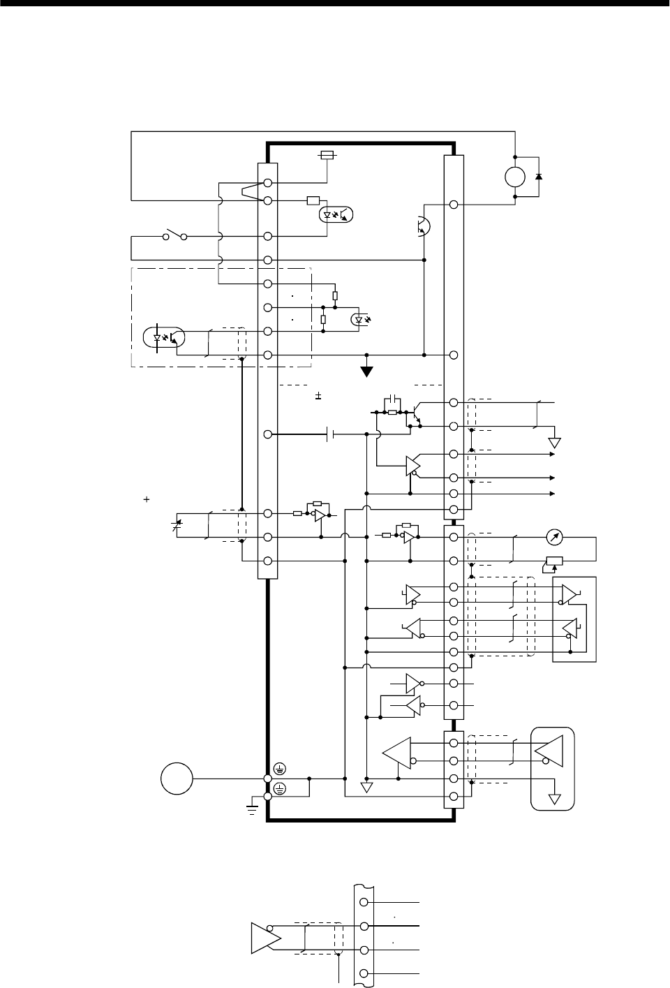
3 - 40
3. SIGNALS AND WIRING
3.6 Interfaces
3.6.1 Common line
The following diagram shows the power supply and its common line.
DC24V
CN1A
CN1B
CN1A
CN1B
DO-1
SG
OPC
PG NG
SG
P15R
LG
TLA
VC etc.
SD
OP
MR
MRR
M
DI-1
COM
VDD
ALM .etc
LG
SD
SDP
SDN
RDP
RDN
LG
CN3
RA
CN2
SD
MO1
MO2
LG
SG
TXD
RXD RS-232C
RS-422
(Note)
Analog input
( 10V/max. current)
Servo motor
Ground
SD
LG
Servo motor encoder
Isolated
15VDC 10%
30mA
LA etc.
Analog monitor output
SON, etc.
PP NP
LG
Note. For the open collection pulse train input. Make the following connection for the different line driver
pulse train input.
Differential line
driver output
35mA max.
LAR
etc.
SG
PP NP
PG NG
OPC
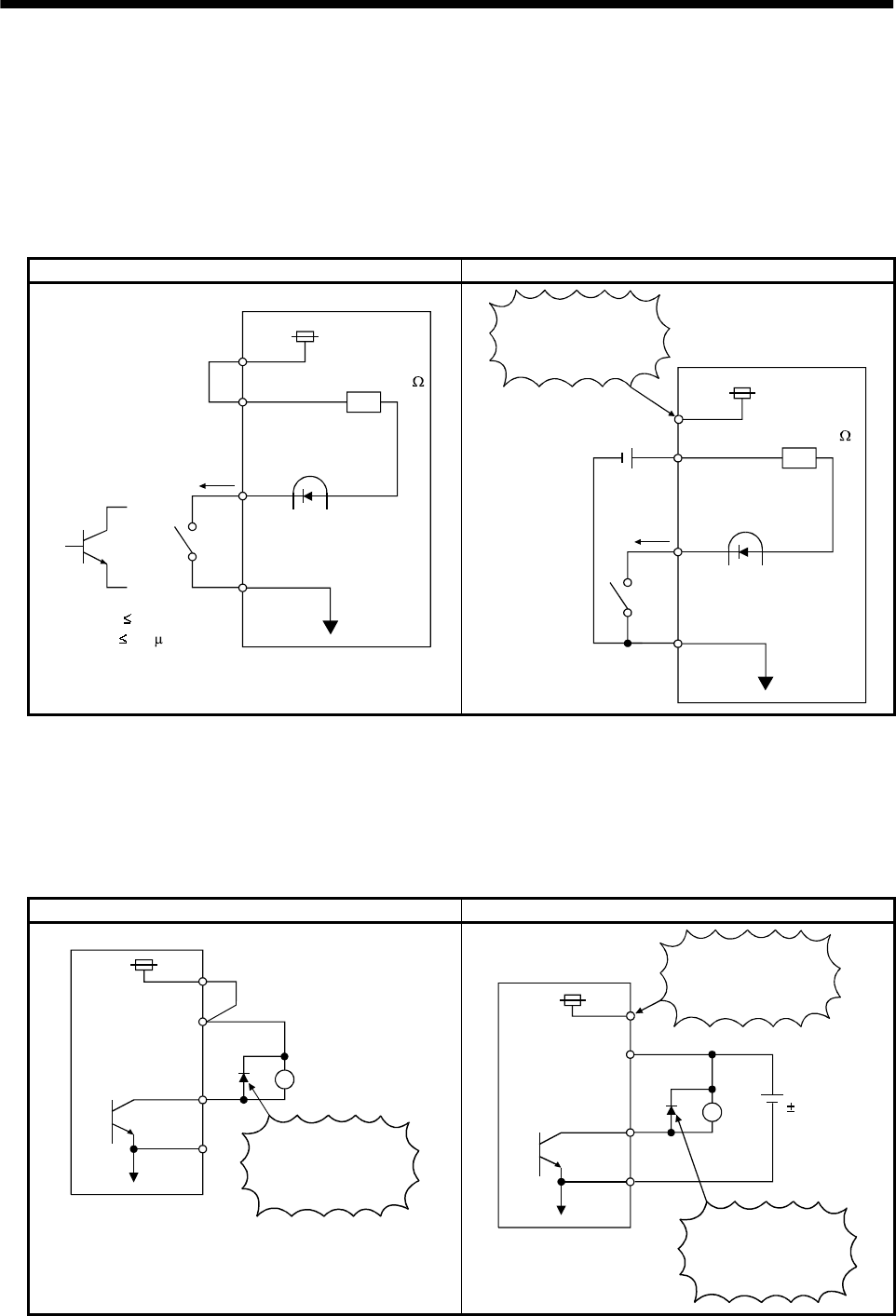
3 - 41
3. SIGNALS AND WIRING
3.6.2 Detailed description of the interfaces
This section gives the details of the I/O signal interfaces (refer to I/O Division in the table) indicated in
Sections 3.3.2.
Refer to this section and connect the interfaces with the external equipment.
(1) Digital input interface DI-1
Give a signal with a relay or open collector transistor.
Source input is also possible. Refer to (7) in this section.
For use of internal power supply For use of external power supply
VDD
COM
24VDC
SGTR
Servo amplifier
R: Approx. 4.7
SON, etc.
(Note)
For a transistor
Approx. 5mA
V CES 1.0V
I CEO 100 A
Switch
COM
SG
Switch
SON, etc.
24VDC
200mA or more
Servo amplifier
R: Approx. 4.7
VDD 24VDC
Do not connect
VDD-COM.
Note. This also applies to the use of the external power supply.
(2) Digital output interface DO-1
A lamp, relay or photocoupler can be driven. Provide a diode (D) for an inductive load, or an inrush
current suppressing resister (R) for a lamp load. (Permissible current: 40mA or less, inrush current:
100mA or less)
(a) Inductive load
For use of internal power supply For use of external power supply
VDD
24VDC
COM
SG
Servo amplifier
If the diode is not
connected as shown,
the servo amplifier
will be damaged.
Load
ALM, etc. 24VDC
10%
COM
SG
Servo amplifier
Load
ALM, etc.
If the diode is not
connected as shown,
the servo amplifier
will be damaged.
VDD
24VDC
Do not connect
VDD-COM.
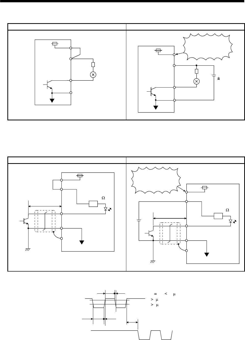
3 - 42
3. SIGNALS AND WIRING
(b) Lamp load
For use of internal power supply For use of external power supply
24VDC VDD
COM
R
Servo amplifier
ALM, etc.
SG
COM
SG
R24VDC
10%
Servo amplifier
ALM, etc.
VDD
24VDC
Do not connect
VDD-COM.
(3) Pulse train input interface DI-2
Provide a pulse train signal in the open collector or differential line driver system.
(a) Open collector system
1) Interface
For use of internal power supply For use of external power supply
VDD
OPC
PP, NP
SG
SD
Servo amplifier
Max. input pulse
frequency 200kpps
About 1.2k
24VDC
2m (78.74in) or less
OPC
PP, NP
SG
SD
24VDC
Servo amplifier
Max. input pulse
frequency 200kpps
About 1.2k
VDD 24VDC
Do not connect
VDD-OPC.
2m (78.74in) or less
2) Conditions of the input pulse
0.9
0.1
tc tHL
tc tLH tF
tLH tHL 0.2 s
tc 2 s
tF 3 s
PP
NP
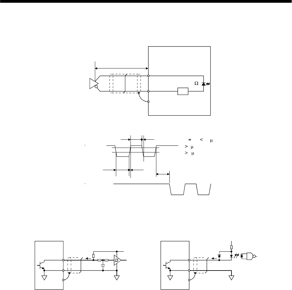
3 - 43
3. SIGNALS AND WIRING
(b) Differential line driver system
1) Interface
SD
PG(NG)
PP(NP)
Max. input pulse
frequency 500kpps
Servo amplifier
Am26LS31 or equivalent
About 100
10m (393.70in) or less
2) Conditions of the input pulse
0.9
PP PG
tc tHL
tc tLH tF
tLH tHL 0.1 s
tc 1 s
tF 3 s
NP NG
0.1
(4) Encoder pulse output DO-2
(a) Open collector system
Interface
Servo amplifier
OP
5 to 24VDC
Photocoupler
SD
Max. output current : 35mA
LG
Servo amplifier
OP
SD
LG
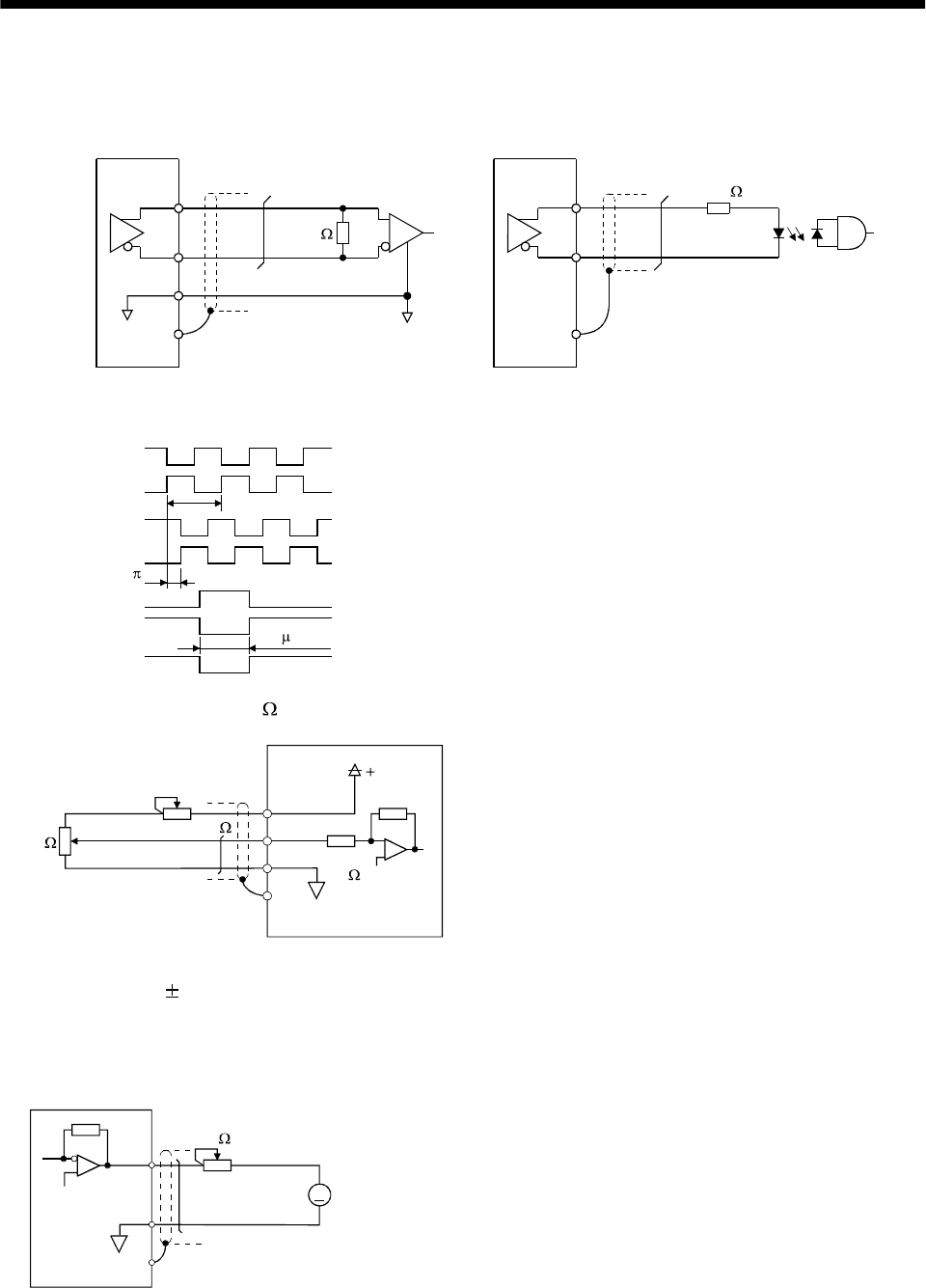
3 - 44
3. SIGNALS AND WIRING
(b) Differential line driver system
1) Interface
Max. output current: 35mA
LA
(LB, LZ)
LAR
(LBR, LZR)
LG
SD
LA
(LB, LZ)
LAR
(LBR, LZR)
SD
Servo amplifier Servo amplifier
Am26LS32 or equivalent High-speed photocoupler
150
100
2) Output pulse
Servo motor CCW rotation
LA
LAR
LB
LBR
LZ
LZR
T
/2
400 s or more
OP
The time cycle (T) is determined by
the setting of the parameter No. 27 and 54.
(5) Analog input
Input impedance 10 to 12k
Upper limit setting 2k
15VDC
P15R
VC‚ etc
LG
SD
2k
Servo amplifier
Approx.
10k
(6) Analog output
Output voltage 10V
Max.1mA
Max. output current
Resolution : 10bit
MO1
(MO2)
LG
SD
A
Servo amplifier
Reading in one or
both directions
1mA meter
10k
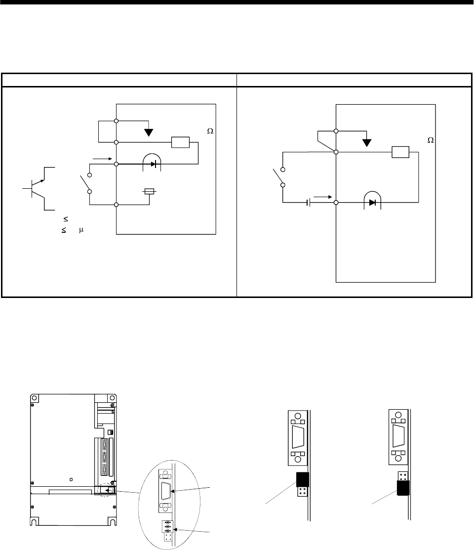
3 - 45
3. SIGNALS AND WIRING
(7) Source input interface
When using the input interface of source type, all Dl-1 input signals are of source type. Source output
cannot be provided.
For use of internal power supply For use of external power supply
SG
COM
24VDC
VDD
TR
R: Approx. 4.7
SON,
etc.
(Note)
For a transistor
Approx. 5mA
VCES 1.0V
ICEO 100 A
Switch
Servo amplifier
SG
COM
24VDC
200mA or more
R: Approx. 4.7
SON,etc.
Switch
Servo amplifier
Note. This also applies to the use of the external power supply.
When using the input interface of source type, all Dl-1 input signals are of source type. Source output
cannot be provided.
For 11kW or more, the source input interface cannot be used with the internal power supply. Always use
the external power supply.
CON2
MITSUB ISHI
JP11
CON2 CON2
JP11 JP11
For sink input (factory setting) For source input
(Note) (Note)
Jumper Jumper
Note. The jumper, which is shown black for the convenience of explanation, is actually white.
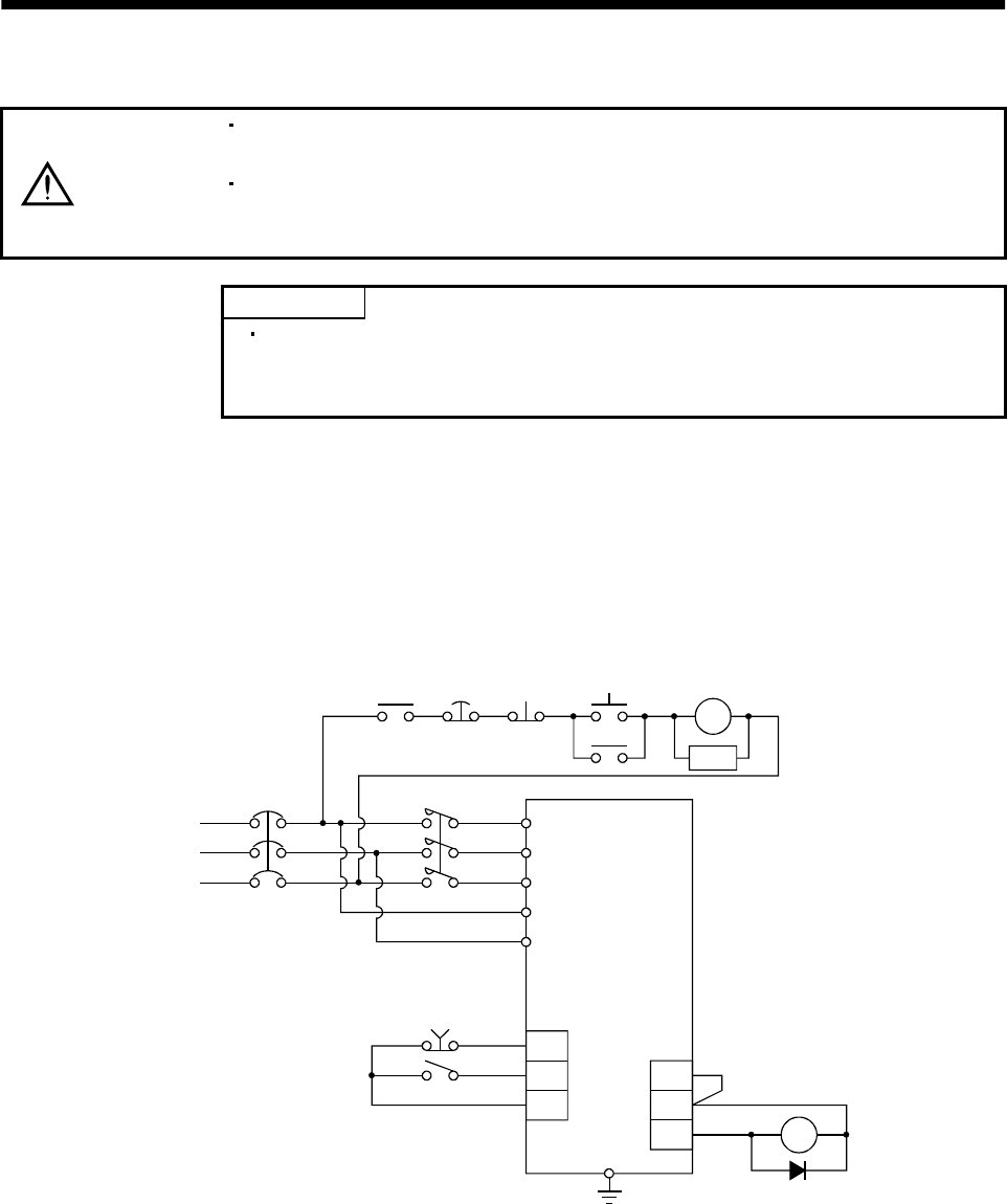
3 - 46
3. SIGNALS AND WIRING
3.7 Input power supply circuit
CAUTION
When the servo amplifier has become faulty, switch power off on the servo
amplifier power side. Continuous flow of a large current may cause a fire.
Use the trouble signal to switch power off. Otherwise, a regenerative brake
transistor fault or the like may overheat the regenerative brake resistor, causing a
fire.
POINT
For the power line circuit of the MR-J2S-11KA to MR-J2S-22KA, refer to
Section 3.13 where the power line circuit is shown together with the servo
motor connection diagram.
3.7.1 Connection example
Wire the power supply and main circuit as shown below so that the servo-on (SON) turns off as soon as
alarm occurrence is detected and power is shut off.
A no-fuse breaker (NFB) must be used with the input cables of the power supply.
(1) For 3-phase 200 to 230VAC power supply
RA OFF
Emergency ON
MC MC
SK
NFB MC
L1
L2
L3
L11
L21
VDD
COM
ALM RA
EMG
SON
SG
Servo-on
Servo amplifier
stop
3-Phase
Trouble
Emergency
stop
200 to 230 VAC
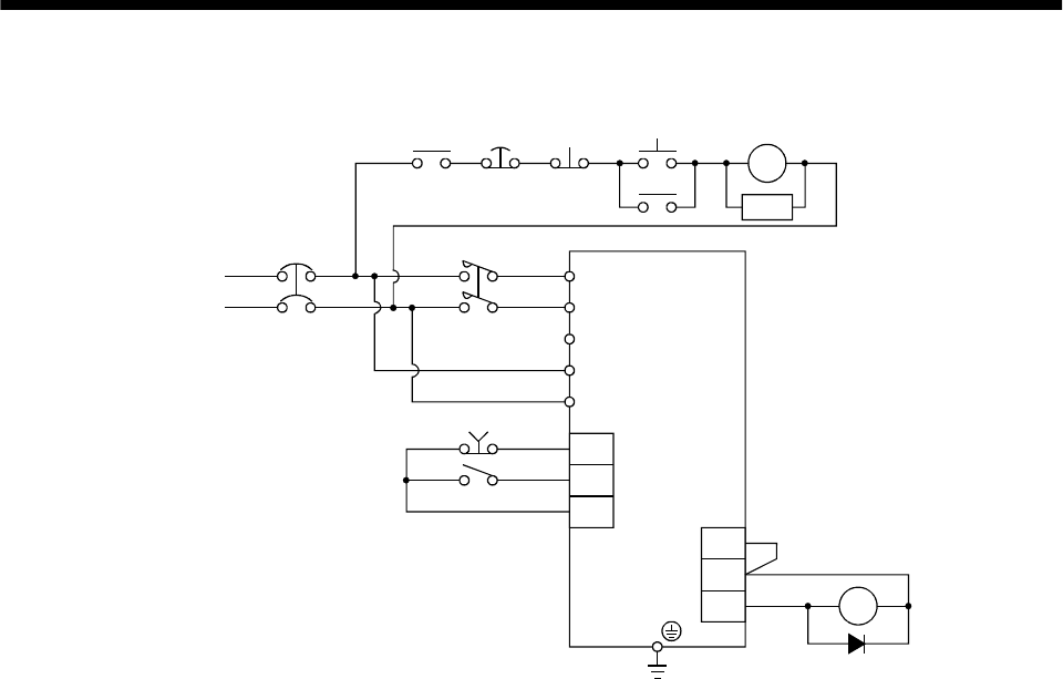
3 - 47
3. SIGNALS AND WIRING
(2) For 1-phase 100 to 120VAC or 1-phase 230VAC power supply
RA OFF ON
MC MC
SK
NFB MC
L1
L2
L3
L11
L21
EMG
SON
SG
VDD
COM
ALM RA
Power supply
1-phase 100 to
120VAC or
1-phase 230VAC
Emergency stop
Servo-on
(Note)
Servo amplifier
Trouble
Emergency
stop
Note. Not provided for 1-phase 100 to 120VAC.
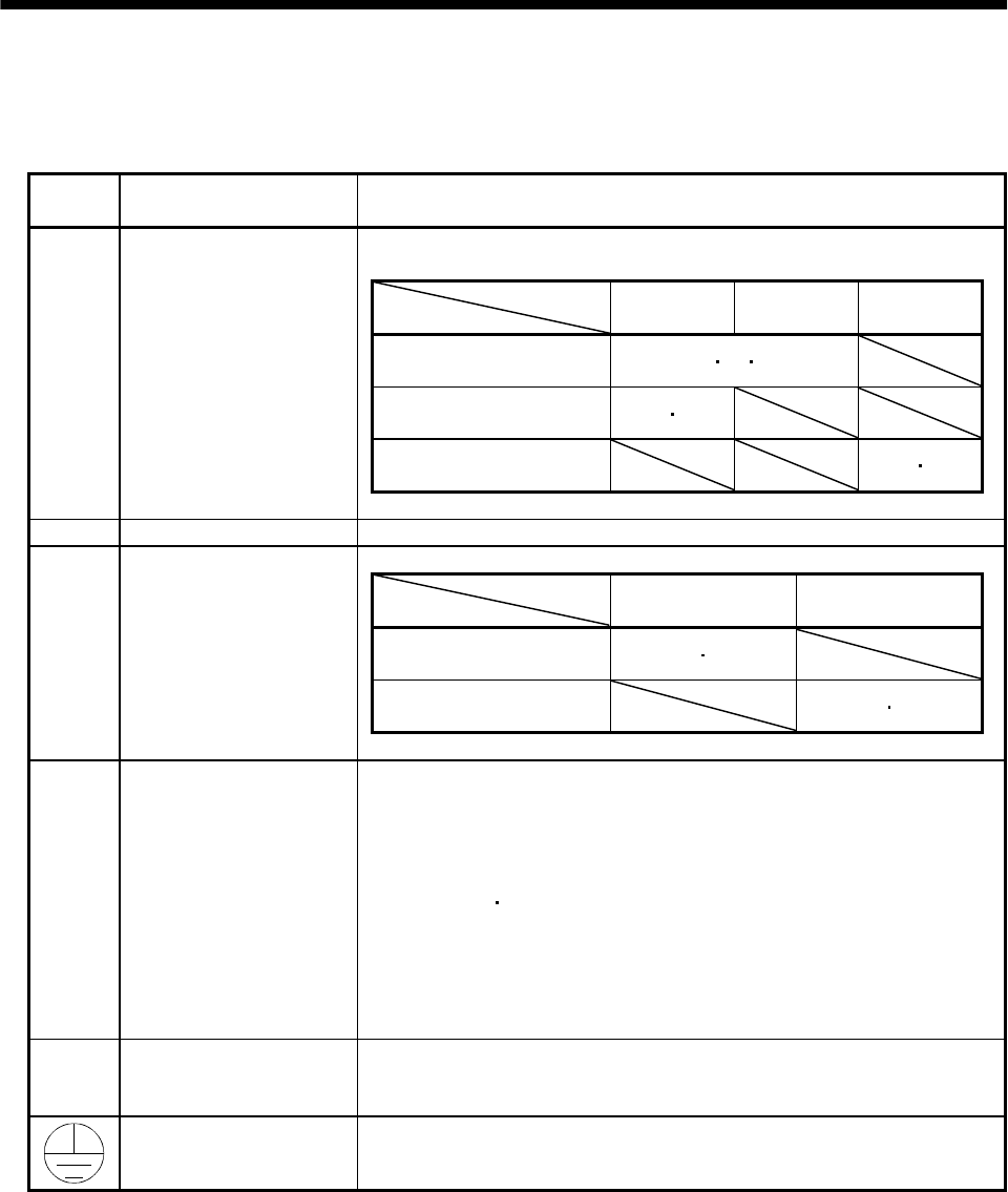
3 - 48
3. SIGNALS AND WIRING
3.7.2 Terminals
The positions and signal arrangements of the terminal blocks change with the capacity of the servo
amplifier. Refer to Section 11.1.
Symbol Connection Target
(Application) Description
Supply L1, L2 and L3 with the following power:
For 1-phase 230VAC, connect the power supply to L1/L2 and leave L3 open.
Servo amplifier
Power supply
MR-J2S-10A to
70A
MR-J2S-100A
to 22kA
MR-J2S-10A1
to 40A1
3-phase 200 to 230VAC,
50/60Hz L1L2L3
1-phase 230VAC,
50/60Hz L1L2
1-phase 100 to 120VAC,
50/60Hz L1L2
L1, L2, L3Main circuit power supply
U, V, W Servo motor output Connect to the servo motor power supply terminals (U, V, W).
Supply L11 and L12 with the following power.
Servo amplifier
Power supply MR-J2S-10A to 700A MR-J2S-10A1 to 40A1
1-phase 200 to 230VAC,
50/60Hz L11 L21
1-phase 100 to 120VAC,
50/60Hz L11 L21
L11, L21 Control circuit power supply
P, C, D Regenerative brake option
1) MR-J2S-350A or less
Wiring is factory-connected across P-D (servo amplifier built-in regenerative
brake resistor).
When using the regenerative brake option, always remove the wiring from
across P-D and connect the regenerative brake option across P-C.
2) MR-J2S-500A 700A
Wiring is factory-connected across P-C (servo amplifier built-in regenerative
brake resistor).
When using the regenerative brake option, always remove the wiring from
across P-C and connect the regenerative brake option across P-C.
Refer to Section 13.1.1 for details.
NReturn converter
Brake unit
When using the return converter or brake unit, connect it across P-N.
Do not connect it to the servo amplifier of MR-J2S-350A or less.
Refer to Sections 13.1.2 and 13.1.3 for details.
Protective earth (PE) Connect this terminal to the protective earth (PE) terminals of the servo motor
and control box for grounding.
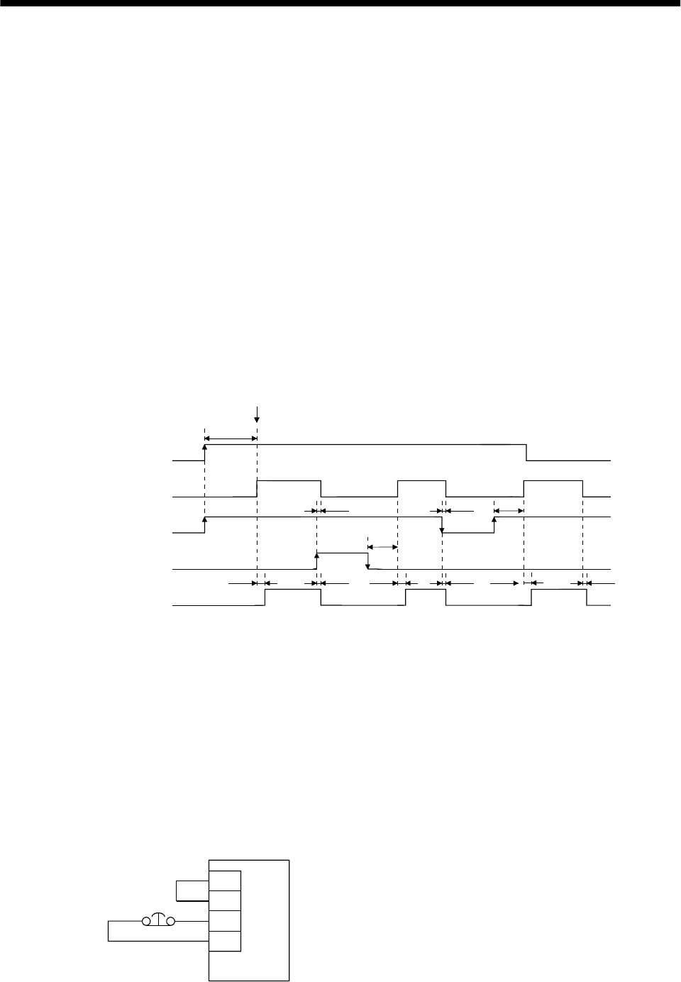
3 - 49
3. SIGNALS AND WIRING
3.7.3 Power-on sequence
(1) Power-on procedure
1) Always wire the power supply as shown in above Section 3.7.1 using the magnetic contactor with
the main circuit power supply (three-phase 200V: L1, L2, L3, single-phase 230V, single-phase 100V:
L1, L2). Configure up an external sequence to switch off the magnetic contactor as soon as an alarm
occurs.
2) Switch on the control circuit power supply L11, L21 simultaneously with the main circuit power
supply or before switching on the main circuit power supply. If the main circuit power supply is not
on, the display shows the corresponding warning. However, by switching on the main circuit power
supply, the warning disappears and the servo amplifier will operate properly.
3) The servo amplifier can accept the servo-on (SON) about 1 to 2s after the main circuit power supply
is switched on. Therefore, when SON is switched on simultaneously with the main circuit power
supply, the base circuit will switch on in about 1 to 2s, and the ready (RD) will switch on in further
about 20ms, making the servo amplifier ready to operate. (Refer to paragraph (2) in this section.)
4) When the reset (RES) is switched on, the base circuit is shut off and the servo motor shaft coasts.
(2) Timing chart
60ms
60ms
OFF
ON
OFF
ON
ON
OFF
OFF
ON
OFF
ON
10ms20ms
10ms
10ms20ms
10ms
20ms 10ms
(1 to 2s)
Servo-on (SON) accepted
Main circuit
Control circuit
Power supply
Base circuit
Servo-on
(SON)
Reset
(RES)
Ready
(RD)
Power-on timing chart
(3) Emergency stop
Make up a circuit that shuts off main circuit power as soon as EMG is turned off at an emergency stop.
When EMG is turned off, the dynamic brake is operated to bring the servo motor to a sudden stop. At
this time, the display shows the servo emergency stop warning (AL.E6).
During ordinary operation, do not use the external emergency stop (EMG) to alternate stop and run.
The servo amplifier life may be shortened.
Also, if the forward rotation start (ST1) and reverse rotation start (ST2) are on or a pulse train is input
during an emergency stop, the servo motor will rotate as soon as the warning is reset. During an
emergency stop, always shut off the run command.
Servo amplifier
EMG
SG
VDD
COM
Emergency stop
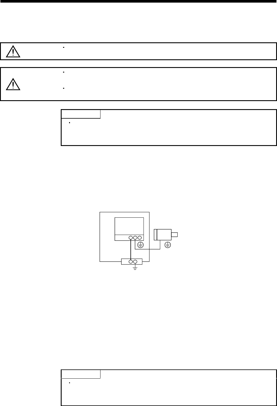
3 - 50
3. SIGNALS AND WIRING
3.8 Connection of servo amplifier and servo motor
3.8.1 Connection instructions
WARNING Insulate the connections of the power supply terminals to prevent an electric
shock.
CAUTION
Connect the wires to the correct phase terminals (U, V, W) of the servo amplifier
and servo motor. Otherwise, the servo motor will operate improperly.
Do not connect AC power supply directly to the servo motor. Otherwise, a fault
may occur.
POINT
Do not apply the test lead bars or like of a tester directly to the pins of the
connectors supplied with the servo motor. Doing so will deform the pins,
causing poor contact.
The connection method differs according to the series and capacity of the servo motor and whether or not
the servo motor has the electromagnetic brake. Perform wiring in accordance with this section.
(1) For grounding, connect the earth cable of the servo motor to the protective earth (PE) terminal of the
servo amplifier and connect the ground cable of the servo amplifier to the earth via the protective
earth of the control box. Do not connect them directly to the protective earth of the control panel.
Servo
amplifier Servo motor
PE terminal
Control box
(2) Do not share the 24VDC interface power supply between the interface and electromagnetic brake.
Always use the power supply designed exclusively for the electromagnetic brake.
3.8.2 Connection diagram
The following table lists wiring methods according to the servo motor types. Use the connection diagram
which conforms to the servo motor used. For cables required for wiring, refer to Section 13.2.1. For
encoder cable connection, refer to Section 13.1.5. For the signal layouts of the connectors, refer to Section
3.8.3.
For the servo motor connector, refer to Chapter 3 of the Servo Motor Instruction Manual.
POINT
For the connection diagram of the MR-J2S-11KA to MR-J2S-22KA, refer
to Section 3.13 where the connection diagram is shown together with the
power line circuit.
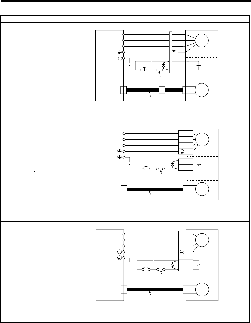
3 - 51
3. SIGNALS AND WIRING
Servo motor Connection diagram
HC-KFS053 (B) to 73 (B)
HC-MFS053 (B) to 73 (B)
HC-UFS13 (B) to 73 (B)
Servo amplifier
(Note 1)
Servo motor
Electromagnetic
brake
24VDC
EMG
(Note 2)
To be shut off when servo-off
or Trouble (ALM)
Encoder cable
CN2
Motor
Encoder
U
V
W
B1
B2
U (Red)
V (White)
W (Black)
(Green)
Note 1. To prevent an electric shock, always connect the protective earth (PE) terminal of the
servo amplifier to the protective earth (PE) of the control box.
2. This circuit applies to the servo motor with electromagnetic brake.
HC-SFS121 (B) to 301 (B)
HC-SFS202 (B) 702 (B)
HC-SFS203 (B) 353 (B)
HC-UFS202 (B) to 502 (B)
HC-RFS353 (B) to 503 (B)
Electromagnetic
brake
(Note 2)
To be shut off when servo-off
or Trouble (ALM)
24VDC
EMG
CN2
U
V
W
U
V
W
B1
B2
Servo amplifier
(Note 1)
Encoder
Encoder cable
Motor
Servo motor
Note 1. To prevent an electric shock, always connect the protective earth (PE) terminal of the
servo amplifier to the protective earth (PE) of the control box.
2. This circuit applies to the servo motor with electromagnetic brake.
HC-SFS81 (B)
HC-SFS52 (B) to 152 (B)
HC-SFS53 (B) to 153 (B)
HC-RFS103 (B) to 203 (B)
HC-UFS72 (B) 152 (B)
Electromagnetic
brake
(Note 2)
To be shut off when servo-off
or Trouble (ALM)
24VDC
EMG
CN2
U
V
W
U
V
W
B1
B2
Servo amplifier
(Note 1)
Encoder
Encoder cable
Motor
Servo motor
Note 1. To prevent an electric shock, always connect the protective earth (PE) terminal of the
servo amplifier to the protective earth (PE) of the control box.
2. This circuit applies to the servo motor with electromagnetic brake.
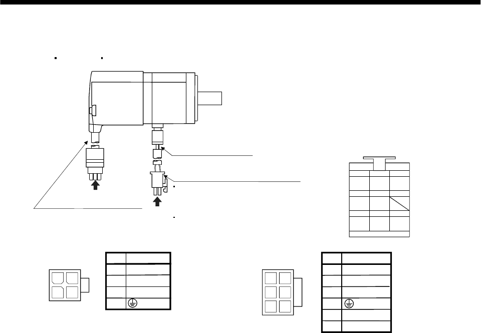
3 - 52
3. SIGNALS AND WIRING
3.8.3 I/O terminals
(1) HC-KFS HC-MFS HC-UFS3000r/min series
24
13
4
Power supply connector (Molex)
Without electromagnetic brake
5557-04R-210 (receptacle)
5556PBTL (Female terminal)
With electromagnetic brake
5557-06R-210 (receptacle)
5556PBTL (Female terminal)
Encoder cable 0.3m (0.98ft.)
Power supply lead
4-AWG19 0.3m (0.98ft.)
With connector 1-172169-9
(Tyco Electronics)
1
2
3
4
1
25
4
36
1
2
3
5
6
Power supply
connector
5557-04R-210 Pin Signal
(Earth)
U
V
W
Power supply
connector
5557-06R-210 Pin Signal
(Earth)
U
V
W
MR
123
MRR BAT
MD
456
MDR
P5
789
LG SHD
Encoder connector signal arrangemen
t
B1
B2
(Note)
(Note)
Note. For the motor with
electromagnetic brake,
supply electromagnetic
brake power (24VDC).
There is no polarity.
a
b
View b
View b
View a
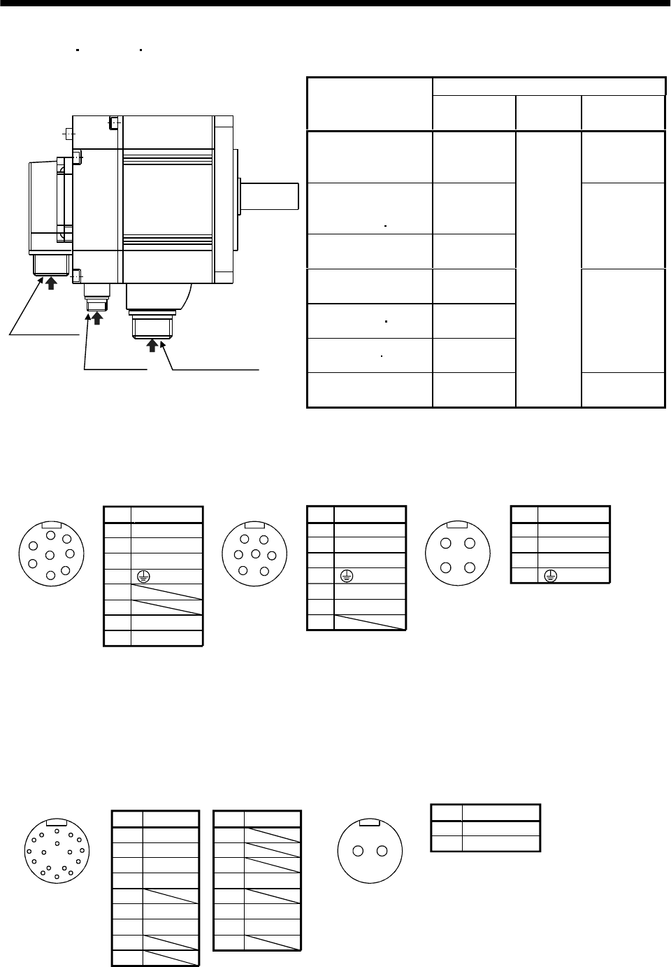
3 - 53
3. SIGNALS AND WIRING
(2) HC-SFS HC-RFS HC-UFS2000 r/min series
Servo motor side connectors
Servo motor For power supply For encoder Electromagnetic
brake connector
HC-SFS81(B)
HC-SFS52(B) to 152(B)
HC-SFS53(B) to 153(B)
CE05-2A22-
23PD-B
The connector
for power is
shared.
HC-SFS121(B) to 301(B)
HC-SFS202(B) to 502 (B)
HC-SFS203(B) 353(B)
CE05-2A24-
10PD-B
HC-SFS702(B) CE05-2A32-
17PD-B
MS3102A10SL-
4P
HC-RFS103(B) to 203 (B) CE05-2A22-
23PD-B
HC-RFS353(B) 503(B) CE05-2A24-
10PD-B
HC-UFS72(B) 152(B) CE05-2A22-
23PD-B
The connector
for power is
shared.
Encoder connector
Brake connector Power supply connector
a
b
c
HC-UFS202(B) to 502(B) CE05-2A24-
10PD-B
MS3102A20-
29P
MS3102A10SL-
4P
Pin
A
B
C
D
E
F
G
H
Signal
U
V
W
(Note) B2
(Earth)
Key
(Note) B1
CE05-2A22-23PD-B
Power supply connector signal arrangement
Pin
A
B
C
D
E
F
G
U
V
W
CE05-2A24-10PD-B
Signal
(Earth)
(Note) B2
(Note) B1
Note. For the motor with
electromagnetic brake,
supply electromagnetic
brake power (24VDC).
There is no polarity.
View c View c
D
CB
A
A
B
C
D
E
FG
H
A
B
C
D
E
F
G
Pin
A
B
C
D
U
V
W
Signal
(Earth)
Key Key
CE05-2A32-17PD-B
Note. For the motor with
electromagnetic brake,
supply electromagnetic
brake power (24VDC).
There is no polarity.
Pin
A
B
C
D
E
F
G
H
J
Signal
MR
MRR
BAT
LG
Pin
K
L
M
N
P
R
S
T
Signal
SD
LG
P5
Encoder connector signal arrangement
MS3102A20-29P
Key
MD
MDR
F
View a
Pin
A
B
Signal
(Note)B1
(Note)B2
Electromagnetic brake connector signal arrangemen
t
MS3102A10SL-4P
Key
View b
A
G
HF
JE
KD
LMBC
N
SR
T P ABNote. For the motor with
electromagnetic brake,
supply electromagnetic
brake power (24VDC).
There is no polarity.
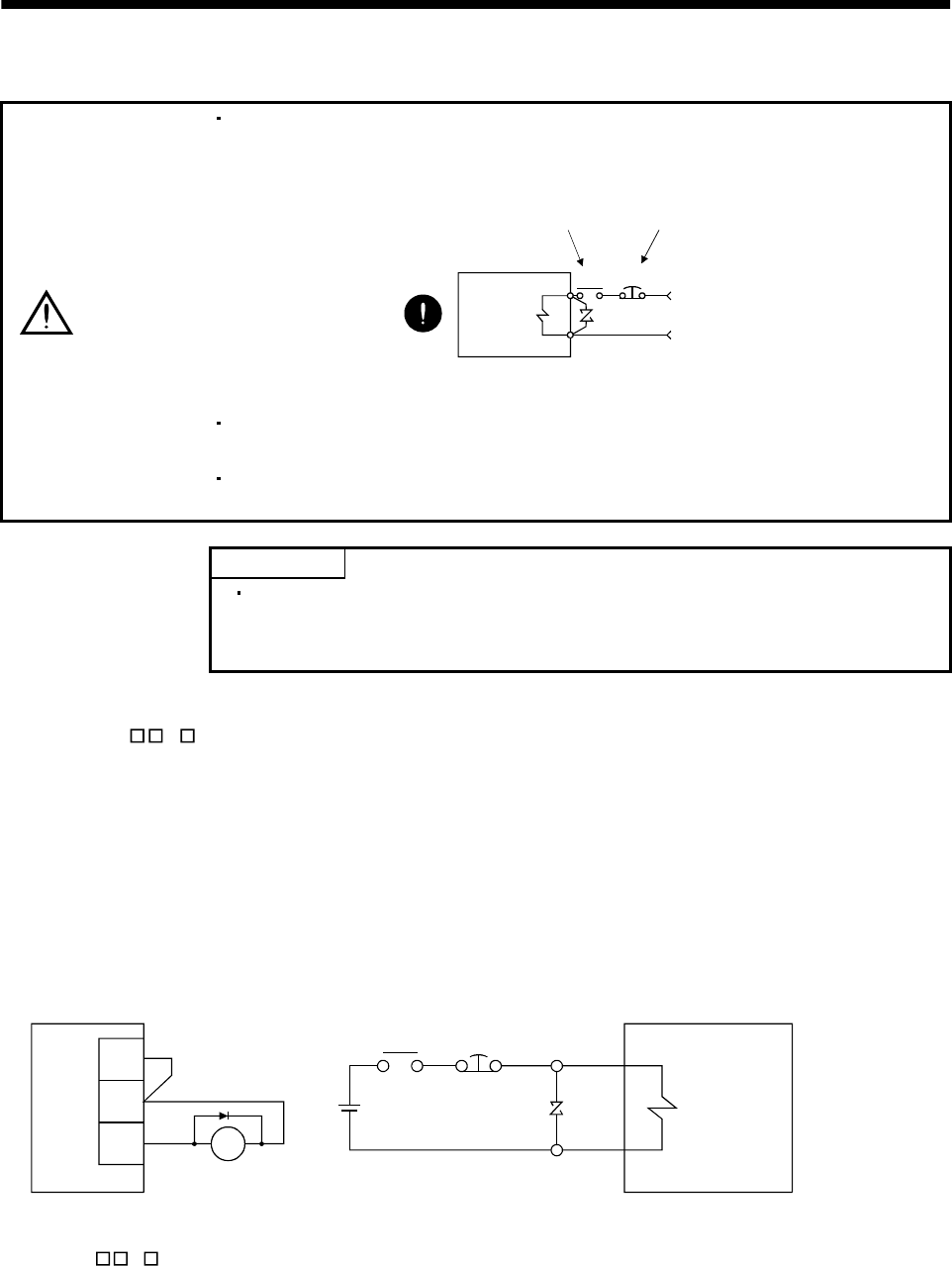
3 - 54
3. SIGNALS AND WIRING
3.9 Servo motor with electromagnetic brake
CAUTION
Configure the electromagnetic brake operation circuit so that it is activated not only
by the servo amplifier signals but also by an external emergency stop signal.
EMGRA
24VDC
Contacts must be open when
servo-off, when an trouble (ALM)
and when an electromagnetic brake
interlock (MBR).
Electromagnetic brake
Servo motor
Circuit must be
opened during
emergency stop (EMG).
The electromagnetic brake is provided for holding purpose and must not be used
for ordinary braking.
Before performing the operation, be sure to confirm that the elecromagnetic brake
operates properly.
POINT
Refer to the Servo Motor Instruction Manual for specifications such as the
power supply capacity and operation delay time of the electromagnetic
brake.
Note the following when the servo motor equipped with electromagnetic brake is used:
1) Set " 1 " in parameter No.1 to make the electromagnetic brake interlock (MBR) valid. Note
that this will make the zero speed signal (ZSP) unavailable.
2) Do not share the 24VDC interface power supply between the interface and electromagnetic
brake. Always use the power supply designed exclusively for the electromagnetic brake.
3) The brake will operate when the power (24VDC) switches off.
4) While the reset (RES) is on, the base circuit is shut off. When using the servo motor with a
vertical shaft, use the electromagnetic brake interlock (MBR).
5) Switch off the servo-on (SON) after the servo motor has stopped.
(1) Connection diagram
MBR
COM
Servo amplifier Servo motor
B1
B2
Emergency
stop
RA
24VDC
RA
VDD
(2) Setting
1) Set " 1 " in parameter No.1 to make the electromagnetic brake interlock (MBR) valid.
2) Using parameter No. 33 (electromagnetic brake sequence output), set a time delay (Tb) at servo-off
from electromagnetic brake operation to base circuit shut-off as in the timing chart shown in (3) in
this section.
3 - 55
3. SIGNALS AND WIRING
(3) Timing charts
(a) Servo-on (SON) command (from controller) ON/OFF
Tb [ms] after the servo-on (SON) signal is switched off, the servo lock is released and the servo
motor coasts. If the electromagnetic brake is made valid in the servo lock status, the brake life may
be shorter. Therefore, when using the electromagnetic brake in a vertical lift application or the
like, set Tb to about the same as the electromagnetic brake operation delay time to prevent a drop.
Servo motor speed
Electromagnetic
brake (MBR)
ON
OFF
Base circuit
Invalid(ON)
Valid(OFF)
ON
OFF
Servo-on(SON)
Electromagnetic brake
operation delay time
Tb
Coasting
0 r/min
(60ms)
(80ms)
(b) Emergency stop (EMG) ON/OFF
Servo motor speed
Electromagnetic
brake interlock (MBR)
ON
OFF
Base circuit
Invalid (ON)
Valid (OFF)
Emergency stop (EMG)
(10ms) (180ms)
(180ms)
Dynamic brake
Dynamic brake
Electromagnetic brake
Electromagnetic brake
Invalid (ON)
Valid (OFF)
Electromagnetic brake
operation delay time
Electromagnetic brake release
3 - 56
3. SIGNALS AND WIRING
(c) Alarm occurrence
Servo motor speed
ON
OFF
Base circuit
Electromagnetic
brake interlock (MBR)
Invalid(ON)
Valid(OFF)
Trouble (ALM) No(ON)
Yes(OFF)
Dynamic brake
Dynamic brake
Electromagnetic brake
Electromagnetic brake
operation delay time
Electromagnetic brake
(10ms)
(d) Both main and control circuit power supplies off
Servo motor speed
ON
OFF
Base circuit
Electromagnetic
brake interlock(MBR)
Invalid(ON)
Valid(OFF)
Trouble (ALM) No(ON)
Yes(OFF)
ON
OFF
Main circuit
Dynamic brake
Dynamic brake
Electromagnetic brake
Electromagnetic brake
Control circuit
power
(Note)
15 to 60ms
(10ms)
(10ms or less)
Electromagnetic brake
operation delay time
Note. Changes with the operating status.
(Note 2)
(e) Only main circuit power supply off (control circuit power supply remains on)
Servo motor speed
ON
OFF
Base circuit
Electromagnetic
brake interlock
(MBR)
Invalid(ON)
Valid(OFF)
Trouble (ALM) No(ON)
Yes(OFF)
ON
OFF
Main circuit power
supply
Dynamic brake
Dynamic brake
Electromagnetic brake
Electromagnetic brake
(Note 1)
15ms or more
Electromagnetic brake
operation delay time
(Note 2)
Note 1. Changes with the operating status.
2. When the main circuit power supply is off in a motor stop status,
the main circuit off warning (A.E9) occurs and the trouble (ALM) does not turn off.
(10ms)
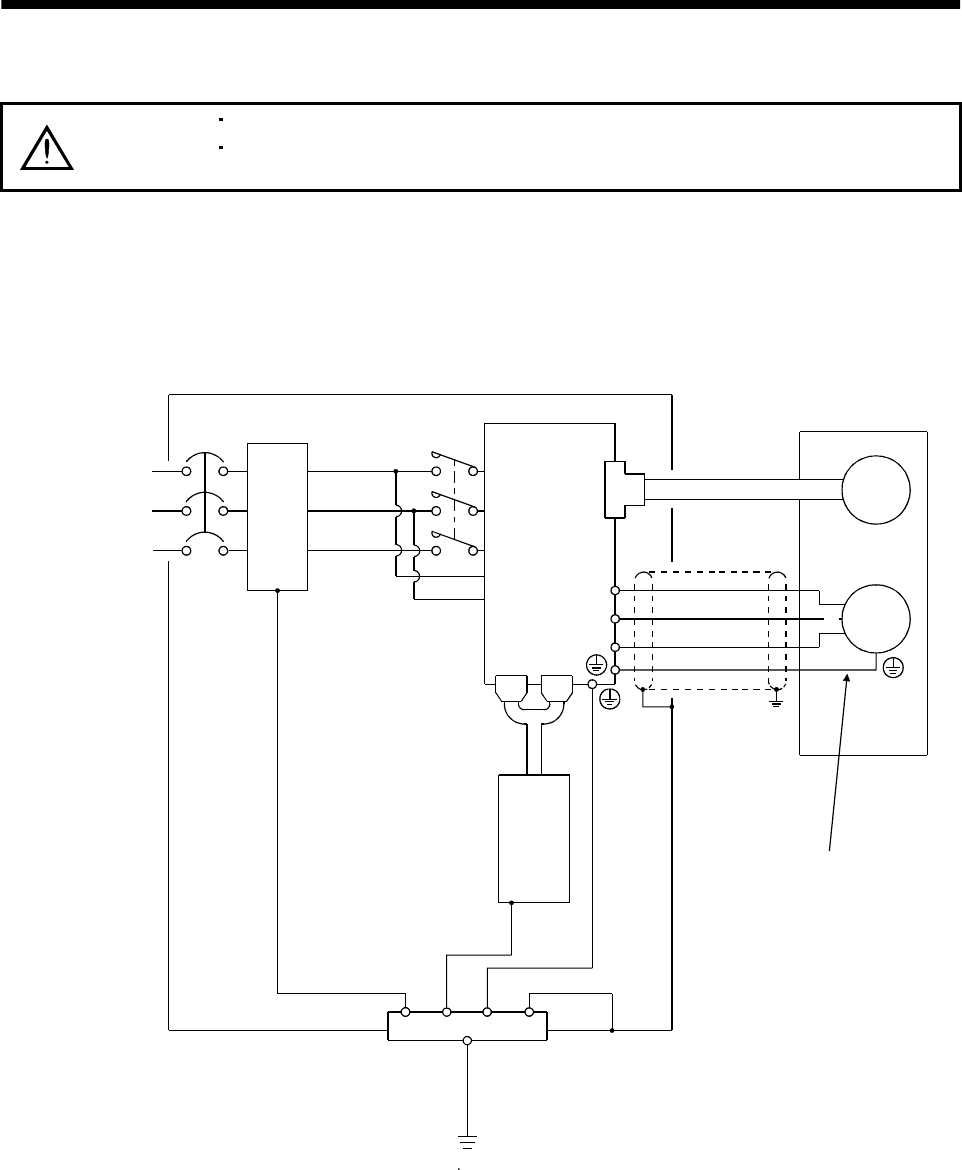
3 - 57
3. SIGNALS AND WIRING
3.10 Grounding
WARNING
Ground the servo amplifier and servo motor securely.
To prevent an electric shock, always connect the protective earth (PE) terminal of
the servo amplifier with the protective earth (PE) of the control box.
The servo amplifier switches the power transistor on-off to supply power to the servo motor. Depending on
the wiring and ground cablerouting, the servo amplifier may be affected by the switching noise (due to
di/dt and dv/dt) of the transistor. To prevent such a fault, refer to the following diagram and always
ground.
To conform to the EMC Directive, refer to the EMC Installation Guidelines (IB(NA)67310).
Control box
Servo amplifier
L1
L2
L3
L11
L21
CN1A CN1B
Line filter
NFB MC
Protective earth(PE)
CN2
U
V
W
Outer
box
Servo motor
Ensure to connect it to PE
terminal of the servo amplifier.
Do not connect it directly to
the protective earth of
the control panel.
Encoder
M
U
V
W
(Note)
Power supply
3-phase
200 to 230VAC,
1-phase
230VAC or
1-phase
100 to 120VAC
Note. For 1-phase 230VAC, connect the power supply to L1 L2 and leave L3 open.
Programmable
controller
There is no L3 for 1-phase 100 to 120VAC power supply.
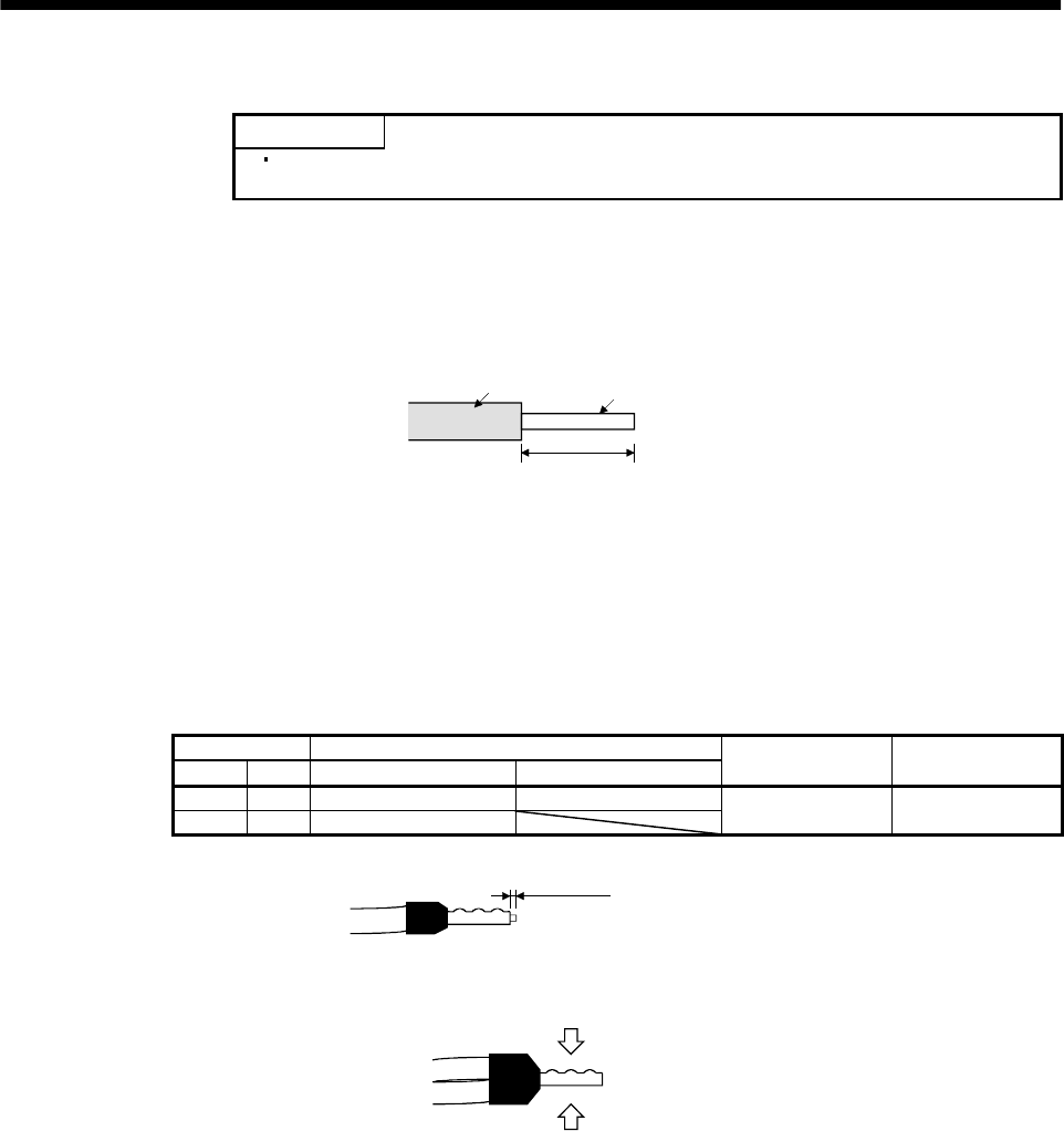
3 - 58
3. SIGNALS AND WIRING
3.11 Servo amplifier terminal block (TE2) wiring method
POINT
Refer to Table 13.1 (2) and (4) in Section 13.2.1 for the wire sizes used for
wiring.
3.11.1 For the servo amplifier produced later than Jan. 2006
(1) Termination of the cables
(a) Solid wire
After the sheath has been stripped, the cable can be used as it is.
Sheath Core
Approx. 10mm
(b) Twisted wire:
1)When the wire is inserted directly
Use the cable after stripping the sheath and twisting the core. At this time, take care to
avoid a short caused by the loose wires of the core and the adjacent pole. Do not solder the
core as it may cause a contact fault. Alternatively, a bar terminal may be used to put the
wires together.
2) When the wires are put together
Using a bar terminal.
Cable Size Bar Terminal Type
[mm2] AWG For 1 cable For 2 cables Crimping Tool Maker
1.25/1.5 16 AI1.5-10BK AI-TWIN×1.5-10BK
2/2.5 14 AI2.5-10BU CRIMPFOX ZA 3 Phoenix Contact
Cut the wire running out of bar terminal to less than 0.5mm.
Less than 0.5mm
When using a bar terminal for two wires, insert the wires in the direction where the
insulation sleeve does not interfere with the next pole and pressure them.
Pressure
Pressure
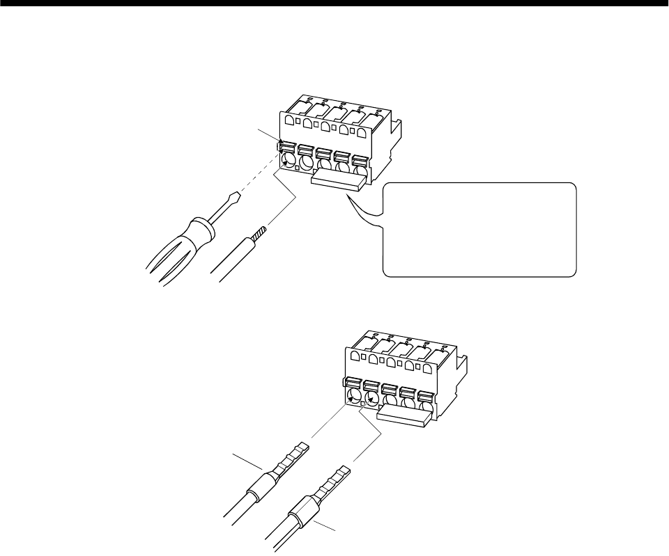
3 - 59
3. SIGNALS AND WIRING
(2) Termination of the cables
(a) When the wire is inserted directly
Insert the wire to the end pressing the button with a small flat blade screwdriver or the like.
Button
Small flat blade
screwdriver or the like
Twisted wire
When removing the short-circuit bar
from across P-D, press the buttons
of P and D alternately pulling the
short-circuit bar. For the installation,
insert the bar straight to the end.
(b) When the wires are put together using a bar terminal
Insert a bar terminal with the odd-shaped side of the pressured terminal on the button side.
Bar terminal for one
wire or solid wire
Bar terminal for two wires
When the two wires are inserted into one opening, a bar terminal for two wires is required.
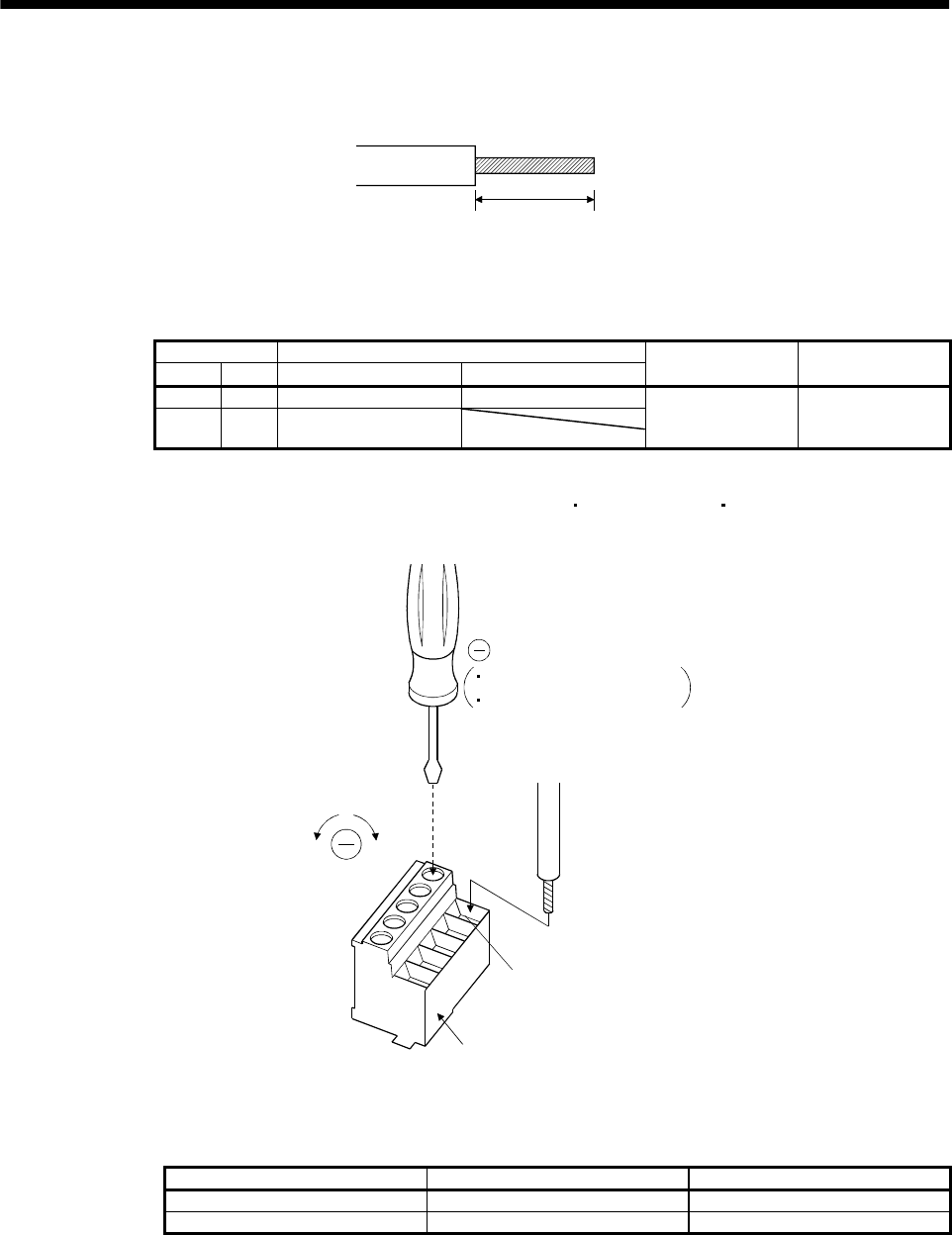
3 - 60
3. SIGNALS AND WIRING
3.11.2 For the servo amplifier produced earlier than Dec. 2005
(1) Termination of the cables
Solid wire: After the sheath has been stripped, the cable can be used as it is.
Approx. 10mm
(0.39inch)
Twisted wire: Use the cable after stripping the sheath and twisting the core. At this time, take care to
avoid a short caused by the loose wires of the core and the adjacent pole. Do not solder
the core as it may cause a contact fault. Alternatively, a bar terminal may be used to put
the wires together.
Cable Size Bar Terminal Type
[mm2]AWG For 1 cable For 2 cables Crimping Tool Maker
1.25/1.5 16 AI1.5-10BK AI-TWIN×1.5-10BK
2/2.5 14 AI2.5-10BU CRIMPFOX ZA 3
or
CRIMPFOX UD 6 Phoenix Contact
(2) Connection
Insert the core of the cable into the opening and tighten the screw with a flat-blade screwdriver so that
the cable does not come off. (Tightening torque: 0.3 to 0.4N m(2.7 to 3.5 lb in)) Before inserting the
cable into the opening, make sure that the screw of the terminal is fully loose.
When using a cable of 1.5mm2 or less, two cables may be inserted into one opening.
To loosen. To tighten.
Opening
Control circuit terminal block
Cable
Flat-blade screwdriver
Tip thickness 0.4 to 0.6mm
Overall width 2.5 to 3.5mm
Use of a flat-blade torque screwdriver is recommended to manage the screw tightening torque. The
following table indicates the recommended products of the torque screwdriver for tightening torque
management and the flat-blade bit for torque screwdriver. When managing torque with a Phillips bit,
please consult us.
Product Model Maker/Representative
Torque screwdriver N6L TDK Nakamura Seisakusho
Bit for torque screwdriver B-30, flat-blade, H3.5 X 73L Shiro Sangyo
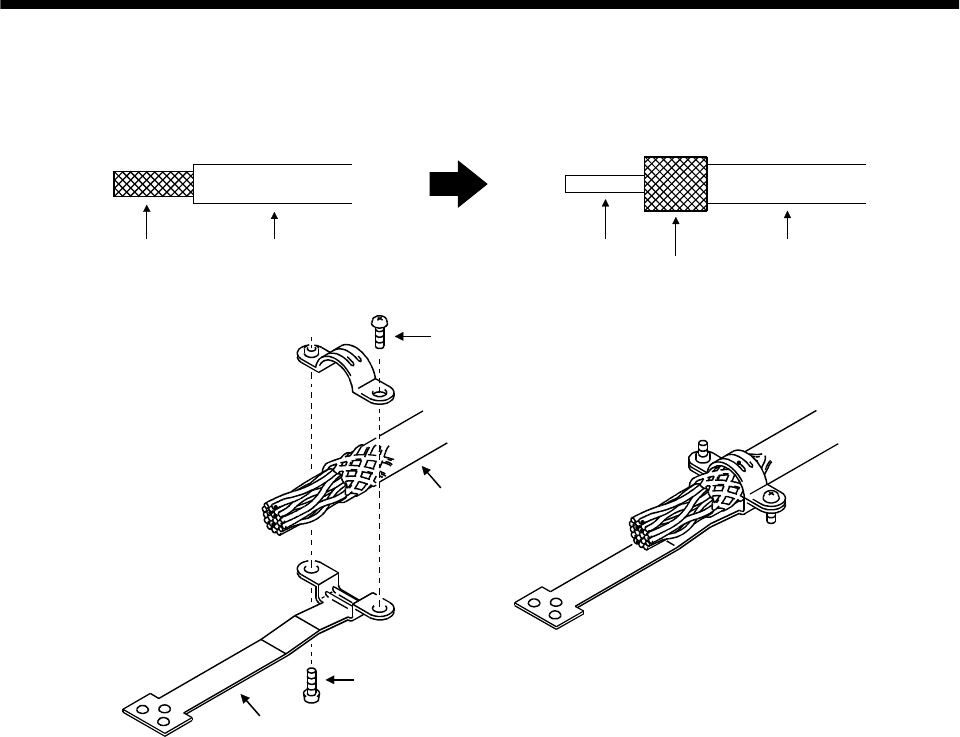
3 - 61
3. SIGNALS AND WIRING
3.12 Instructions for the 3M connector
When fabricating an encoder cable or the like, securely connect the shielded external conductor of the
cable to the ground plate as shown in this section and fix it to the connector shell.
External conductor Sheath External conductor
Pull back the external conductor to cover the sheath
SheathCore
Strip the sheath.
Screw
Screw
Ground plate
Cable
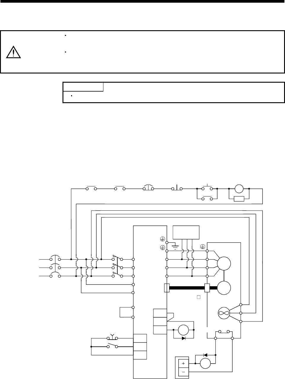
3 - 62
3. SIGNALS AND WIRING
3.13 Power line circuit of the MR-J2S-11KA to MR-J2S-22KA
CAUTION
When the servo amplifier has become faulty, switch power off on the amplifier
power side. Continuous flow of a large current may cause a fire.
Use the trouble (ALM) to switch power off. Otherwise, a regenerative brake
transistor fault or the like may overheat the regenerative brake resistor, causing a
fire.
POINT
The power-on sequence is the same as in Section 5.7.3.
3.13.1 Connection example
Wire the power supply/main circuit as shown below so that power is shut off and the servo-on signal
turned off as soon as an alarm occurs, a servo emergency stop is made valid, a controller emergency stop,
or a servo motor thermal relay alarm is made valid. A no-fuse breaker (NFB) must be used with the input
cables of the power supply.
L1
L2
L3
L11
L21
EMG
SON
SG
CN2
U
V
W
U
V
W
M
BU
RA2
BV
BW
MC
SK
ON
MC
NFB MC
OHS2OHS1
ALM
COM
VDD
RA1
Servo motor
thermal relay
RA2
Alarm
RA1 emergency stop OFF
3-phase
200 to 230VAC
Servo amplifier (Note1)
Dynamic
break Servo motor
HA-LFS series
Encoder
Fan (Note2
)
Servo motor
thermal relay
24VDC
power supply
Emergency stop
servo-on
MR-JHSCBL M
cable
2. There is no BW when the HA-LFS11K2 is used.
Note 1. When using the external dynamic break, refer to section 13.1.4.
Trouble
3. Always connect P-P1. (Factory-wired.) When using the power factor improving DC reactor,
refer to Section 13.2.4
P
P1
(Note3)

3 - 63
3. SIGNALS AND WIRING
3.13.2 Servo amplifier terminals
The positions and signal arrangements of the terminal blocks change with the capacity of the servo
amplifier. Refer to Section 11.1.
Symbol Connection Target
(Application) Description
L1, L2, L3Main circuit power supply Supply L1, L2 and L3 with three-phase 200 to 230VAC, 50/60Hz power.
U, V, W Servo motor output Connect to the servo motor power supply terminals (U, V, W).
L11, L21 Control circuit power supply Supply L11 and L21 with single-phase 200 to 230VAC power.
P, C Regenerative brake option
The servo amplifier built-in regenerative brake resistor is not connected at the
time of shipment.
When using the regenerative brake option, wire it across P-C.
Refer to Section 13.1.1 for details.
NReturn converter
Brake unit When using the return converter or brake unit, connect it across P-N.
Refer to Sections 13.1.2 and 13.1.3 for details.
Protective earth (PE) Connect this terminal to the protective earth (PE) terminals of the servo motor
and control box for grounding.
P1, P Power factor improving DC
reactors P1-P are connected before shipment. When connecting a power factor improving
DC reactor, remove the short bar across P1-P. Refer to Section 13.2.4 for details.
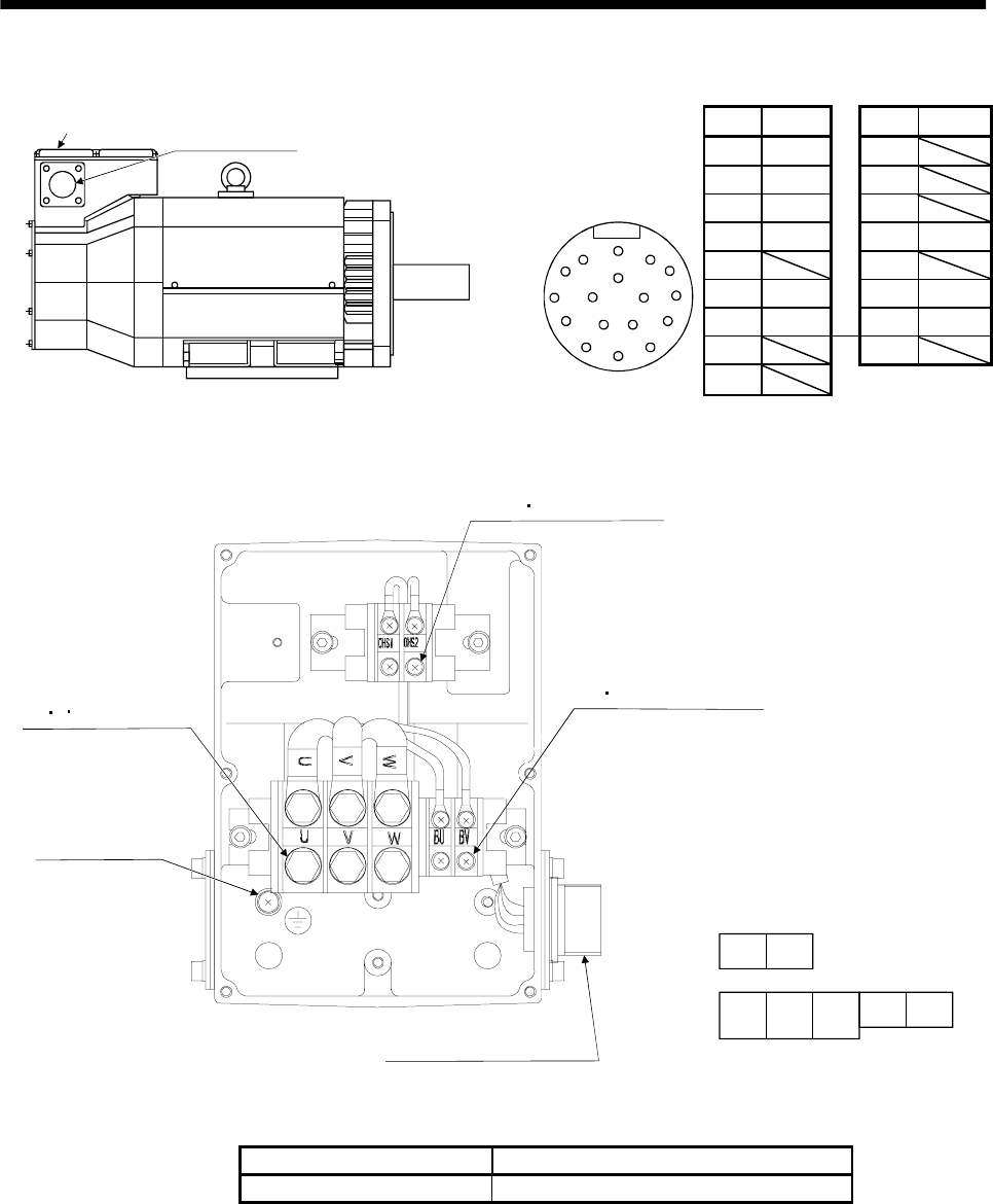
3 - 64
3. SIGNALS AND WIRING
3.13.3 Servo motor terminals
Pin Signal Pin Signal
AMD K
BMDR L
CMR M
DMRR NSHD
EP
FBAT R LG
GLG S P5
HT
Terminal box Encoder connector
MS3102A20-29P
Key
A
N
G
S R
TP
HF
JE
KD
LM B C
Encoder connector
signal arrangement
MS3102A20-29P
J
Terminal box inside (HA-LFS11K2)
Earth terminal
M6 screw
Motor power supply
terminal block
(U V W) M6 screw
Thermal sensor
terminal block
(OHS1 OHS2) M4 screw
Cooling fan terminal block
(BU BV) M4screw
Encoder commector
MS3102A20-29P
UVW
BU BV
OHS1OHS2
Terminal block signal arrangemen
t
Power supply connection screw size
Servo motor Power supply connection screw size
HA-LFS11K2 M6
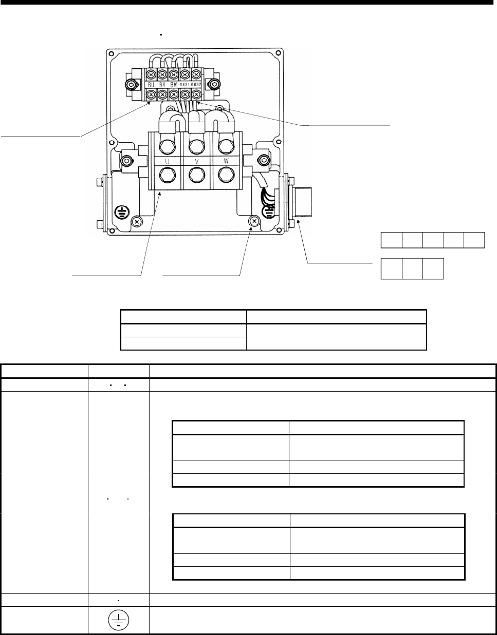
3 - 65
3. SIGNALS AND WIRING
Terminal box inside (HA-LFS15K2 HA-LFS-22K2)
Earth terminal M6 screw
Thermal sensor terminal
block (OHS1, OHS2)
M4 screw
Cooling fan terminal
block (BU, BV, BW)
M4 screw
Moter power supply
terminal block
(U, V, W) M8 screw
Encoder connector
MS3102A20-29P
UVW
BU BV OHS1OHS2BW
Terminal block signal arrangemen
t
Power supply connection screw size
Servo motor Power supply connection screw size
HA-LFS15K2
HA-LFS22K2 M8
Signal Name Abbreviation Description
Power supply U VW Connect to the motor output terminals (U, V, W) of the servo amplifier.
Supply power which satisfies the following specifications.
HA-LFS11K2
Item Description
Voltage/frequency single-phase 200 to 220VAC, 50Hz
single-phase 200 to 230VAC, 60Hz
Power consumption [W] 42(50Hz)/54(60Hz)
Rated voltage [V] 0.12(50Hz)/0.25(60Hz)
HA-LFS15K2/22K2
Item Description
Voltage/frequency Three-phase 200 to 220VAC, 50Hz
Three-phase 200 to 230VAC, 60Hz
Power consumption [W] 32(50Hz)/40(60Hz)
Rated voltage [V] 0.30(50Hz)/0.25(60Hz)
Cooling fan (Note)
BU BV BW
Motor thermal relay OHS1 OHS2 OHS1-OHS2 are opened when heat is generated to an abnormal temperature.
Earth terminal For grounding, connect to the earth of the control box via the earth terminal of the servo
amplifier.
Note. There is no BW when the HA-LFS11K2 is used.

3 - 66
3. SIGNALS AND WIRING
MEMO

4 - 1
4. OPERATION
4. OPERATION
4.1 When switching power on for the first time
Before starting operation, check the following:
(1) Wiring
(a) A correct power supply is connected to the power input terminals (L1, L2, L3, L11, L21) of the servo
amplifier.
(b) The servo motor power supply terminals (U, V, W) of the servo amplifier match in phase with the
power input terminals (U, V, W) of the servo motor.
(c) The servo motor power supply terminals (U, V, W) of the servo amplifier are not shorted to the
power input terminals (L1, L2, L3) of the servo motor.
(d) The earth terminal of the servo motor is connected to the PE terminal of the servo amplifier.
(e) Note the following when using the regenerative brake option, brake unit or power regeneration
converter:
1) For the MR-J2S-350A or less, the lead has been removed from across D-P of the control circuit
terminal block, and twisted cables are used for its wiring.
2) For the MR-J2S-500A or more, the lead has been removed from across P-C of the servo amplifier
built-in regenerative brake resistor, and twisted cables are used for its wiring.
(f) When stroke end limit switches are used, LSP and LSN are on during operation.
(g) 24VDC or higher voltages are not applied to the pins of connectors CN1A and CN1B.
(h) SD and SG of connectors CN1A and CN1B are not shorted.
(i) The wiring cables are free from excessive force.
(2) Environment
Signal cables and power cables are not shorted by wire offcuts, metallic dust or the like.
(3) Machine
(a) The screws in the servo motor installation part and shaft-to-machine connection are tight.
(b) The servo motor and the machine connected with the servo motor can be operated.
4 - 2
4. OPERATION
4.2 Startup
WARNING Do not operate the switches with wet hands. You may get an electric shock.
CAUTION
Before starting operation, check the parameters. Some machines may perform
unexpected operation.
Take safety measures, e.g. provide covers, to prevent accidental contact of hands
and parts (cables, etc.) with the servo amplifier heat sink, regenerative brake
resistor, servo motor, etc.since they may be hot while power is on or for some time
after power-off. Their temperatures may be high and you may get burnt or a parts
may damaged.
During operation, never touch the rotating parts of the servo motor. Doing so can
cause injury.
Connect the servo motor with a machine after confirming that the servo motor operates properly alone.
4.2.1 Selection of control mode
Use parameter No. 0 to choose the control mode used. After setting, this parameter is made valid by
switching power off, then on.
4.2.2 Position control mode
(1) Power on
1) Switch off the servo-on (SON).
2) When main circuit power/control circuit power is switched on, the display shows "C (Cumulative
feedback pulses)", and in two second later, shows data.
In the absolute position detection system, first power-on results in the absolute position lost (AL.25)
alarm and the servo system cannot be switched on. This is not a failure and takes place due to the
uncharged capacitor in the encoder.
The alarm can be deactivated by keeping power on for a few minutes in the alarm status and then
switching power off once and on again.
Also in the absolute position detection system, if power is switched on at the servo motor speed of
500r/min or higher, position mismatch may occur due to external force or the like. Power must
therefore be switched on when the servo motor is at a stop.
(2) Test operation 1
Using jog operation in the test operation mode, operate at the lowest speed to confirm that the servo
motor operates. (Refer to Section 6.8.2.)
(3) Parameter setting
Set the parameters according to the structure and specifications of the machine. Refer to Chapter 5 for
the parameter definitions and to Sections 6.5 for the setting method.
Parameter No. Name Setting Description
0Control mode, regenerative brake
option selection
3 0 Position control mode
MR-RB12 regenerative brake option is used.
1 Function selection 1
0 0 2 Input filter 3.555ms (initial value)
Electromagnetic brake interlock signal is not used.
Used in incremental positioning system.
2 Auto tuning 1 5 Middle response (initial value) is selected.
Auto tuning mode 1 is selected.
3 Electronic gear numerator (CMX) 1 Electronic gear numerator
4 Electronic gear denominator (CDV) 1 Electronic gear denominator
After setting the above parameters, switch power off once. Then switch power on again to make
the set parameter values valid.

4 - 3
4. OPERATION
(4) Servo-on
Switch the servo-on in the following procedure:
1) Switch on main circuit/control circuit power supply.
2) Switch on the servo-on (SON).
When placed in the servo-on status, the servo amplifier is ready to operate and the servo motor is
locked.
(5) Command pulse input
Entry of a pulse train from the positioning device rotates the servo motor. At first, run it at low speed
and check the rotation direction, etc. If it does not run in the intended direction, check the input
signal.
On the status display, check the speed, command pulse frequency, load factor, etc. of the servo motor.
When machine operation check is over, check automatic operation with the program of the positioning
device.
This servo amplifier has a real-time auto tuning function under model adaptive control. Performing
operation automatically adjusts gains. The optimum tuning results are provided by setting the
response level appropriate for the machine in parameter No. 2. (Refer to chapter 7)
(6) Home position return
Make home position return as required.
(7) Stop
In any of the following statuses, the servo amplifier interrupts and stops the operation of the servo
motor:
Refer to Section 3.9, (2) for the servo motor equipped with electromagnetic brake. Note that the stop
pattern of stroke end (LSP/LSN) OFF is as described below.
(a) Servo-on (SON) OFF
The base circuit is shut off and the servo motor coasts.
(b) Alarm occurrence
When an alarm occurs, the base circuit is shut off and the dynamic brake is operated to bring the
servo motor to a sudden stop.
(c) Emergency stop (EMG) OFF
The base circuit is shut off and the dynamic brake is operated to bring the servo motor to a sudden
stop. Alarm AL.E6 occurs.
(d) Forward rotation stroke end (LSP), reverse rotation stroke end (LSN) OFF
The droop pulse value is erased and the servo motor is stopped and servo-locked. It can be run in
the opposite direction.
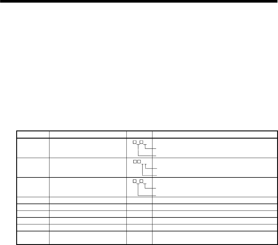
4 - 4
4. OPERATION
4.2.3 Speed control mode
(1) Power on
1) Switch off the servo-on (SON).
2) When main circuit power/control circuit power is switched on, the display shows "r (servo motor
speed)", and in two second later, shows data.
(2) Test operation
Using jog operation in the test operation mode, operate at the lowest speed to confirm that the servo
motor operates. (Refer to Section 6.8.2.)
(3) Parameter setting
Set the parameters according to the structure and specifications of the machine. Refer to Chapter 5 for
the parameter definitions and to Sections 6.5 for the setting method.
Parameter No. Name Setting Description
0Control mode, regenerative brake
option selection
0 2 Speed control mode
Regenerative brake option is not used.
1 Function selection 1 1 2 Input filter 3.555ms (initial value)
Electromagnetic brake interlock (MBR) is used.
2 Auto tuning 1 5 Middle response (initial value) is selected.
Auto tuning mode 1 is selected.
8 Internal speed command 1 1000 Set 1000r/min.
9 Internal speed command 2 1500 Set 1500r/min.
10 Internal speed command 3 2000 Set 2000r/min.
11 Acceleration time constant 1000 Set 1000ms.
12 Deceleration time constant 500 Set 500ms.
13 S-pattern acceleration/deceleration
time constant 0 Not used
After setting the above parameters, switch power off once. Then switch power on again to make
the set parameter values valid.
(4) Servo-on
Switch the servo-on in the following procedure:
1) Switch on main circuit/control circuit power supply.
2) Switch on the servo-on (SON).
When placed in the servo-on status, the servo amplifier is ready to operate and the servo motor is
locked.
(5) Start
Using speed selection 1 (SP1) and speed selection 2 (SP2), choose the servo motor speed. Turn on
forward rotation start (ST1) to run the motor in the forward rotation (CCW) direction or reverse
rotation start (ST2) to run it in the reverse rotation (CW) direction. At first, set a low speed and check
the rotation direction, etc. If it does not run in the intended direction, check the input signal.
On the status display, check the speed, load factor, etc. of the servo motor.
When machine operation check is over, check automatic operation with the host controller or the like.
This servo amplifier has a real-time auto tuning function under model adaptive control. Performing
operation automatically adjusts gains. The optimum tuning results are provided by setting the
response level appropriate for the machine in parameter No. 2. (Refer to chapter 7)
4 - 5
4. OPERATION
(6) Stop
In any of the following statuses, the servo amplifier interrupts and stops the operation of the servo
motor:
Refer to Section 3.9, (2) for the servo motor equipped with electromagnetic brake. Note that
simultaneous ON or simultaneous OFF of stroke end (LSP, LSN) OFF and forward rotation start
(ST1) or reverse rotation start (ST2) has the same stop pattern as described below.
(a) Servo-on (SON) OFF
The base circuit is shut off and the servo motor coasts.
(b) Alarm occurrence
When an alarm occurs, the base circuit is shut off and the dynamic brake is operated to bring the
servo motor to a sudden stop.
(c) Emergency stop (EMG) OFF
The base circuit is shut off and the dynamic brake is operated to bring the servo motor to a sudden
stop. Alarm AL.E6 occurs.
(d) Stroke end (LSP/LSN) OFF
The servo motor is brought to a sudden stop and servo-locked. The motor may be run in the
opposite direction.
(e) Simultaneous ON or simultaneous OFF of forward rotation start (ST1) and reverse rotation start
(ST2)
The servo motor is decelerated to a stop.
POINT
A sudden stop indicates deceleration to a stop at the deceleration time
constant of zero.
4.2.4 Torque control mode
(1) Power on
1) Switch off the servo-on (SON).
2) When main circuit power/control circuit power is switched on, the display shows "U (torque
command voltage)", and in two second later, shows data.
(2) Test operation
Using jog operation in the test operation mode, operate at the lowest speed to confirm that the servo
motor operates. (Refer to Section 6.8.2.)
(3) Parameter setting
Set the parameters according to the structure and specifications of the machine. Refer to Chapter 5 for
the parameter definitions and to Sections 6.5 for the setting method.
Parameter No. Name Setting Description
0Control mode, regenerative brake
option selection 0 4 Torque control mode
Regenerative brake option is not used.
1 Function selection 1 0 2 Input filter 3.555ms (initial value)
Electromagnetic brake interlock (MBR) is not used.
8 Internal speed limit 1 1000 Set 1000r/min.
9 Internal speed limit 2 1500 Set 1500r/min.
10 Internal speed limit 3 2000 Set 2000r/min.
11 Acceleration time constant 1000 Set 1000ms.
12 Deceleration time constant 500 Set 500ms.
13 S-pattern acceleration/deceleration time
constant 0 Not used
14 Torque command time constant 2000 Set 2000ms
28 Internal torque limit 1 50 Controlled to 50% output
After setting the above parameters, switch power off once. Then switch power on again to make the set
parameter values valid.

4 - 6
4. OPERATION
(4) Servo-on
Switch the servo-on in the following procedure:
1) Switch on main circuit/control circuit power supply.
2) Switch on the servo-on (SON).
When placed in the servo-on status, the servo amplifier is ready to operate.
(5) Start
Using speed selection 1 (SP1) and speed selection 2 (SP2), choose the servo motor speed. Turn on
forward rotation select (DI4) to run the motor in the forward rotation (CCW) direction or reverse
rotation select (DI3) to run it in the reverse rotation (CW) direction, generating torque. At first, set a
low speed and check the rotation direction, etc. If it does not run in the intended direction, check the
input signal.
On the status display, check the speed, load factor, etc. of the servo motor.
When machine operation check is over, check automatic operation with the host controller or the like.
(6) Stop
In any of the following statuses, the servo amplifier interrupts and stops the operation of the servo
motor:
Refer to Section 3.9, (2) for the servo motor equipped with electromagnetic brake.
(a) Servo-on (SON) OFF
The base circuit is shut off and the servo motor coasts.
(b) Alarm occurrence
When an alarm occurs, the base circuit is shut off and the dynamic brake is operated to bring the
servo motor to a sudden stop.
(c) Emergency stop (EMG) OFF
The base circuit is shut off and the dynamic brake is operated to bring the servo motor to a sudden
stop. Alarm AL.E6 occurs.
(d) Simultaneous ON or simultaneous OFF of forward rotation selection (RS1) and reverse rotation
selection (RS2)
The servo motor coasts.
POINT
A sudden stop indicates deceleration to a stop at the deceleration time
constant of zero.
4.3 Multidrop communication
You can use the RS-422 communication function (parameter No.16) to operate two or more servo
amplifiers on the same bus. In this case, set station numbers to the servo amplifiers to recognize the servo
amplifier to which the current data is being sent. Use parameter No. 15 to set the station numbers.
Always set one station number to one servo amplifier. Normal communication cannot be made if the same
station number is set to two or more servo amplifiers.
For details, refer to Chapter 14.
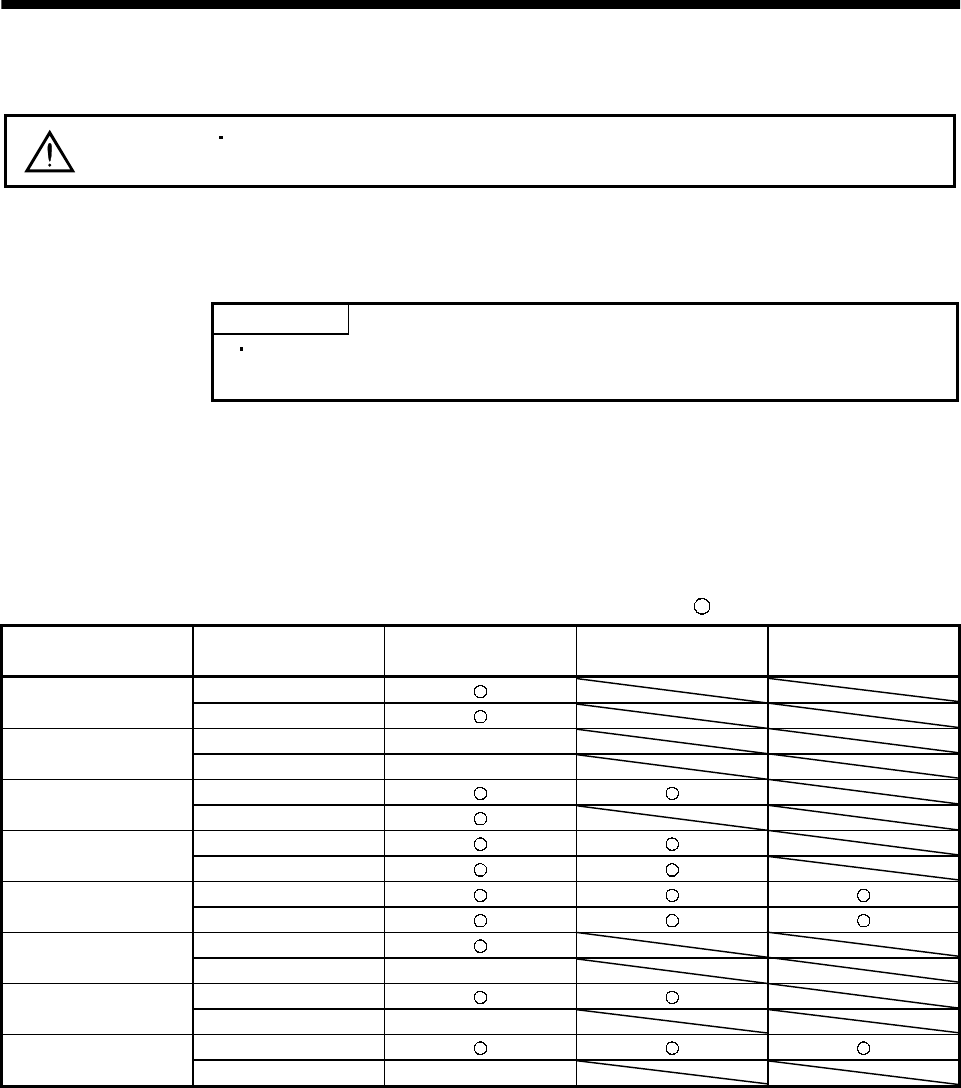
5 - 1
5. PARAMETERS
5. PARAMETERS
CAUTION Never adjust or change the parameter values extremely as it will make operation
instable.
5.1 Parameter list
5.1.1 Parameter write inhibit
POINT
After setting the parameter No. 19 value, switch power off, then on to
make that setting valid.
In the MR-J2S-A servo amplifier, its parameters are classified into the basic parameters (No. 0 to 19),
expansion parameters 1 (No. 20 to 49) and expansion parameters 2 (No.50 to 84) according to their
safety aspects and frequencies of use. In the factory setting condition, the customer can change the
basic parameter values but cannot change the expansion parameter values. When fine adjustment, e.g.
gain adjustment, is required, change the parameter No. 19 setting to make the expansion parameters
write-enabled.
The following table indicates the parameters which are enabled for reference and write by the setting of
parameter No. 19. Operation can be performed for the parameters marked .
Parameter No. 19 setting Operation Basic parameters
No. 0 to No. 19
Expansion parameters 1
No. 20 to No. 49
Expansion parameters 2
No. 50 to No. 84
Reference
0000
(initial value) Write
Reference No. 19 only
000A Write No. 19 only
Reference
000B Write
Reference
000C Write
Reference
000E Write
Reference
100B Write No. 19 only
Reference
100C Write No. 19 only
Reference
100E Write No. 19 only
5 - 2
5. PARAMETERS
5.1.2 Lists
POINT
For any parameter whose symbol is preceded by *, set the parameter
value and switch power off once, then switch it on again to make that
parameter setting valid.
The symbols in the control mode column of the table indicate the following
modes:
P : Position control mode
S : Speed control mode
T : Torque control mode
(1) Item list
No. Symbol Name Control
mode
Initial
value Unit Customer
setting
0 *STY Control mode ,regenerative brake option selection P ST 0000
1 *OP1 Function selection 1 P ST 0002
2 ATU Auto tuning P S
7kW or
less: 0105
11kW or
more:0102
3 CMX Electronic gear numerator P 1
4 CDV Electronic gear denominator P 1
5 INP In-position range P 100 pulse
6 PG1 Position loop gain 1 P
7kW or
less: 35
11kW or
more:19
rad/s
7PST
Position command acceleration/deceleration time constant
(Smoothing) P3ms
Internal speed command 1 S 100 r/min
8SC1
Internal speed limit 1 T 100 r/min
Internal speed command 2 S 500 r/min
9SC2
Internal speed limit 2 T 500 r/min
Internal speed command 3 S 1000 r/min
10 SC3 Internal speed limit 3 T 1000 r/min
11 STA Acceleration time constant S T0ms
12 STB Deceleration time constant S T0ms
13 STC S-pattern acceleration/deceleration time constant S T0ms
14 TQC Torque command time constant T 0 ms
15 *SNO Station number setting P ST0station
16 *BPS Serial communication function selection, alarm history clear P ST 0000
17 MOD Analog monitor output P ST 0100
18 *DMD Status display selection P ST 0000
Basic parameters
19 *BLK Parameter write inhibit P ST 0000
5 - 3
5. PARAMETERS
No. Symbol Name Control
mode
Initial
value Unit Customer
setting
20 *OP2 Function selection 2 P S 0000
21 *OP3 Function selection 3 (Command pulse selection) P 0000
22 *OP4 Function selection 4 P ST 0000
23 FFC Feed forward gain P 0 %
24 ZSP Zero speed P ST50r/min
Analog speed command maximum speed S (Note1)0(r/min)
25 VCM Analog speed limit maximum speed T (Note1)0(r/min)
26 TLC Analog torque command maximum output T 100 %
27 *ENR Encoder output pulses P ST 4000 pulse
/rev
28 TL1 Internal torque limit 1 P ST 100 %
Analog speed command offset S (Note2) mV
29 VCO Analog speed limit offset T (Note2) mV
Analog torque command offset T 0 mV
30 TLO Analog torque limit offset S 0 mV
31 MO1 Analog monitor 1 offset P ST0 mV
32 MO2 Analog monitor 2 offset P ST0 mV
33 MBR Electromagnetic brake sequence output P ST 100 ms
34 GD2 Ratio of load inertia moment to servo motor inertia moment P S700.1
times
35 PG2 Position loop gain 2 P
7kW or
less: 35
11kW or
more:19
rad/s
36 VG1 Speed loop gain 1 P S
7kW or
less:177
11kW or
more:96
rad/s
37 VG2 Speed loop gain 2 P S
7kW or
less:817
11kW or
more:45
rad/s
38 VIC Speed integral compensation P S
7kW or
less: 48
11kW or
more:91
ms
39 VDC Speed differential compensation P S 980
40 For manufacturer setting 0
41 *DIA Input signal automatic ON selection P ST 0000
42 *DI1 Input signal selection 1 P ST 0003
43 *DI2 Input signal selection 2 (CN1B-5) P ST 0111
44 *DI3 Input signal selection 3 (CN1B-14) P ST 0222
45 *DI4 Input signal selection 4 (CN1A-8) P ST 0665
46 *DI5 Input signal selection 5 (CN1B-7) P ST 0770
47 *DI6 Input signal selection 6 (CN1B-8) P ST 0883
48 *DI7 Input signal selection 7 (CN1B-9) P ST 0994
Expansion parameters 1
49 *DO1 Output signal selection 1 P ST 0000
For notes, refer to next page.
5 - 4
5. PARAMETERS
No. Symbol Name Control
mode
Initial
value Unit Customer
setting
50 For manufacturer setting 0000
51 *OP6 Function selection 6 P ST 0000
52 For manufacturer setting 0000
53 *OP8 Function selection 8 P ST 0000
54 *OP9 Function selection 9 P ST 0000
55 *OPA Function selection A P 0000
56 SIC Serial communication time-out selection P ST0 s
57 For manufacturer setting 10
58 NH1 Machine resonance suppression filter 1 P ST 0000
59 NH2 Machine resonance suppression filter 2 P ST 0000
60 LPF Low-pass filter, adaptive vibration suppression control P ST 0000
61 GD2B Ratio of load inertia moment to Servo motor inertia moment 2 P S700.1
times
62 PG2B Position control gain 2 changing ratio P 100 %
63 VG2B Speed control gain 2 changing ratio P S 100 %
64 VICB Speed integral compensation changing ratio P S 100 %
65 *CDP Gain changing selection P S 0000
66 CDS Gain changing condition P S10(Note3)
67 CDT Gain changing time constant P S1ms
68 For manufacturer setting 0
69 CMX2 Command pulse multiplying factor numerator 2 P 1
70 CMX3 Command pulse multiplying factor numerator 3 P 1
71 CMX4 Command pulse multiplying factor numerator 4 P 1
Internal speed command 4 S
72 SC4 Internal speed limit 4 T 200 r/min
Internal speed command 5 S
73 SC5 Internal speed limit 5 T 300 r/min
Internal speed command 6 S
74 SC6 Internal speed limit 6 T 500 r/min
Internal speed command 7 S
75 SC7 Internal speed limit 7 T 800 r/min
76 TL2 Internal torque limit 2 P ST 100 %
77 100
78 10000
79 10
80 10
81 100
82 100
83 100
Expansion parameters 2
84
For manufacturer setting
0000
Note 1. The setting of "0" provides the rated servo motor speed.
2. Depends on the servo amplifier.
3. Depends on the parameter No. 65 setting.
5 - 5
5. PARAMETERS
(2) Details list
Class No. S
y
mbol Name and function Initial
value Unit Setting
range Control
mode
Control mode, regenerative brake option selection
Used to select the control mode and regenerative brake option.
Select the control mode.
0:Position
1:Position and speed
2:Speed
3:Speed and torque
4:Torque
5:Torque and position
0
Selection of regenerative brake option
00: Regenerative brake option or regenerative
brake option is not used with 7kW or less servo
amplifier (The built-in regenerative brake
resistor is used.)
Supplied regenerative brake resistors or
regenerative brake option is used with 11kW
or more servo amplifier
01:FR-RC, FR-BU, FR-CV
02:MR-RB032
03:MR-RB12
04:MR-RB32
05:MR-RB30
06:MR-RB50
08:MR-RB31
09:MR-RB51
0E: When regenerative brake resistors supplied to 11kW
or more are cooled by fans to increase capability
The MR-RB65, 66 and 67 are regenerative brake
options that have encased the GRZG400-2 ,
GRZG400-1 and GRZG400-0.8 , respectively.
When using any of these regenerative brake options,
make the same parameter setting as when using the
GRZG400-2 , GRZG400-1 or GRZG400-0.8
(supplied regenerative brake resistors or
regenerative brake option is used with 11kW or
more servo amplifier).
0000
POINT
Wron
g
settin
g
ma
y
cause the re
g
enerative brake option to burn.
If the re
g
enerative brake option selected is not for use with the
servo amplifier, parameter error (AL.37) occurs.
Basic parameters
0*STY Refer to
Name
and
function
column.
P S T
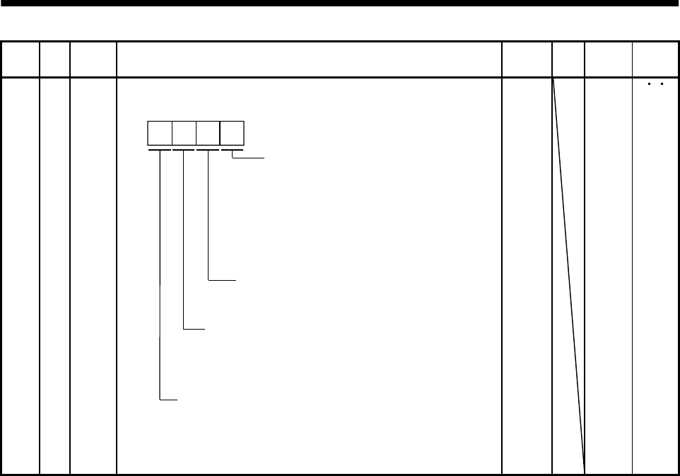
5 - 6
5. PARAMETERS
Class No. Symbol Name and function Initial
value Unit Setting
range
Control
mode
Basic parameters
1*OP1
Function selection 1
Used to select the input si
g
nal filter, pin CN1B-19 function and
absolute position detection system.
Input signal filter
If external input signal causes chattering
due to noise, etc., input filter is used to
suppress it.
0:None
1:1.777[ms]
2:3.555[ms]
3:5.333[ms]
CN1B-pin 19's function selection
0:Zero Speed detection (ZSP)
1:Electromagnetic brake interlock (MBR)
Selection of absolute position detection system
(Refer to Chapter 15)
0: Used in incremental system
1: Used in absolute position detection system
CN1B-pin 18's function selection
0: Alarm (ALM)
1: Dynamic brake interlock (DB)
When using the external dynamic brake with 11kW
or more, make dynamic brake interlock (DB) valid.
0002 Refer to
Name
and
function.
P S T
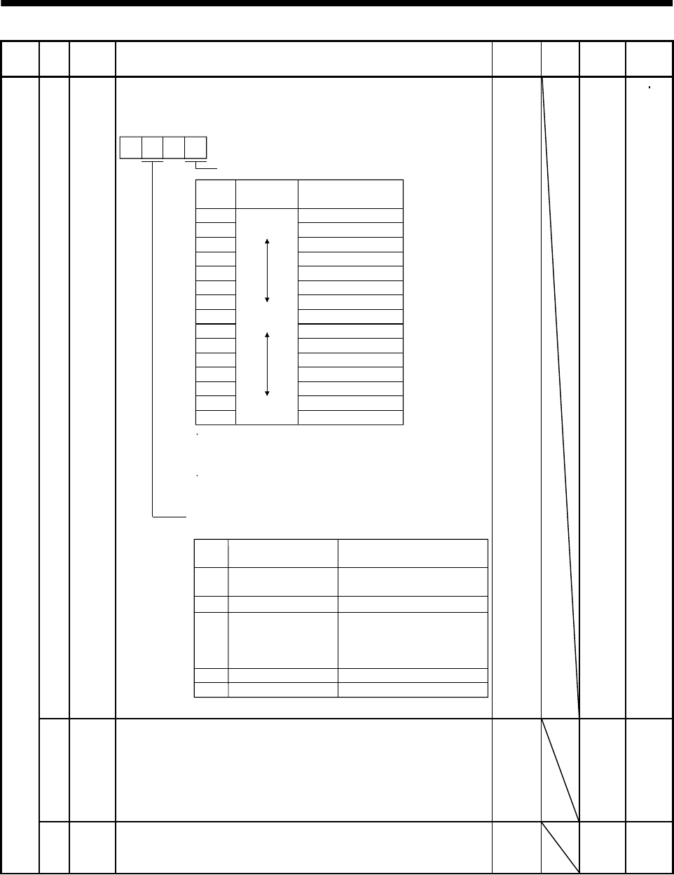
5 - 7
5. PARAMETERS
Class No. Symbol Name and function Initial
value Unit Setting
range
Control
mode
2 ATU Auto tuning
Used to selection the response level, etc. for execution of auto tuning.
Refer to Chapter 7.
Response level setting
If the machine hunts or generates
large gear sound, decrease the
set value.
To improve performance, e.g.
shorten the settling time, increase
the set value.
Set
value
Response
level
1Low
response
Middle
response
High
response
Gain adjustment mode selection
(For more information, refer to Section 7.1.1.)
Machine resonance
frequency guideline
15Hz
220Hz
325Hz
430Hz
535Hz
645Hz
755Hz
870Hz
985Hz
A105Hz
B130Hz
C160Hz
D200Hz
E240Hz
F300Hz
Set
value Gain adjustment mode
0
Description
1
3 Simple manual adjustment.
4 Manual adjustment of all gains.
Interpolation mode Fixes position control gain 1
(parameter No. 6).
Auto tuning mode 1
Fixes the load inertia moment
ratio set in parameter No. 34.
Response level setting can be
changed.
Manual mode 1
Manual mode 2
2Auto tuning mode 2
Ordinary auto tuning.
0 0
7kW or
less: 0105
11kW or
more: 0102
Refer to
Name
and
function
column.
P S
3 CMX Electronic gear numerator
Used to set the electronic gear numerator value.
For the setting, refer to Section 5.2.1.
Setting "0" automatically sets the resolution of the servo motor
connected.
For the HC-MFS series, 131072 pulses are set for example.
10
1
to
65535
P
Basic parameters
4 CDV Electronic gear denominator
Used to set the electronic gear denominator value.
For the setting, refer to Section 5.2.1.
11
to
65535
P
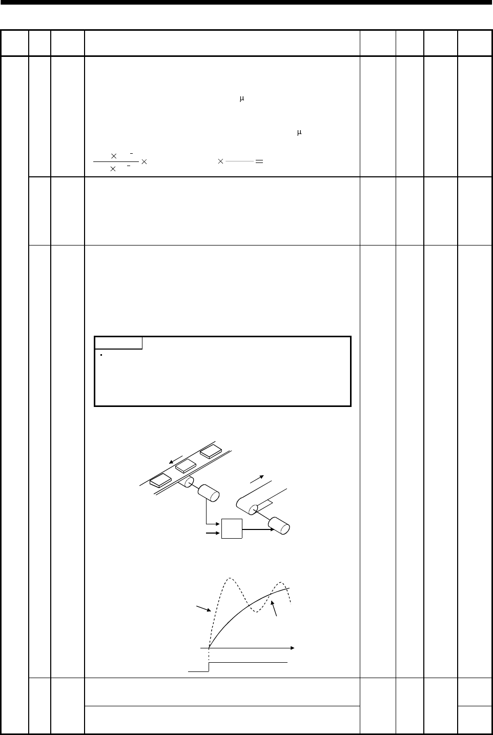
5 - 8
5. PARAMETERS
Class No. Symbol Name and function Initial
value Unit Setting
range
Control
mode
5 INP In-position range
Used to set the in-position (INP) output range in the command pulse
increments prior to electronic gear calculation.
For example, when you want to set 100 m when the ballscrew is
directly coupled, the lead is 10mm, the feedback pulse count is 131072
pulses/rev, and the electronic gear numerator (CMX)/electronic gear
denominator (CDV) is 16384/125 (setting in units of 10 m per pulse),
set "10" as indicated by the following expression.
100 10 6
10 10 3131072[pulse/rev] 16384
125 10
100 pulse 0
to
10000
P
6 PG1 Position loop gain 1
Used to set the gain of position loop.
Increase the gain to improve trackability in response to the position
command.
When auto turning mode 1,2 is selected, the result of auto turning is
automatically used.
7kW or
less: 35
11kW or
more: 19
red/s 4
to
2000
P
Position command acceleration/deceleration time constant
(position smoothing)
Used to set the time constant of a low pass filter in response to the
position command.
You can use parameter No. 55 to choose the primary delay or linear
acceleration/deceleration control system. When you choose linear
acceleration/deceleration, the setting range is 0 to 10ms. Setting of
longer than 10ms is recognized as 10ms.
POINT
7PST
When you have chosen linear acceleration/deceleration, do not
select control selection (parameter No. 0) and restart after
instantaneous power failure (parameter No. 20). Doing so will
cause the servo motor to make a sudden stop at the time of
position control switching or restart.
3ms0
to
20000
P
Example: When a command is given from a synchronizing detector,
synchronous operation can be started smoothly if started during line
operation.
Synchronizing
detector
Start
Servo amplifier
Servo motor
Without time
constant setting
Servo motor
speed
Start
With time
constant setting
ON
OFF t
Internal speed command 1
Used to set speed 1 of internal speed commands.
S
Basic parameters
8SC1
Internal speed limit 1
Used to set speed 1 of internal speed limits.
100 r/min 0 to
instan-
taneous
permi-
ssible
speed
T
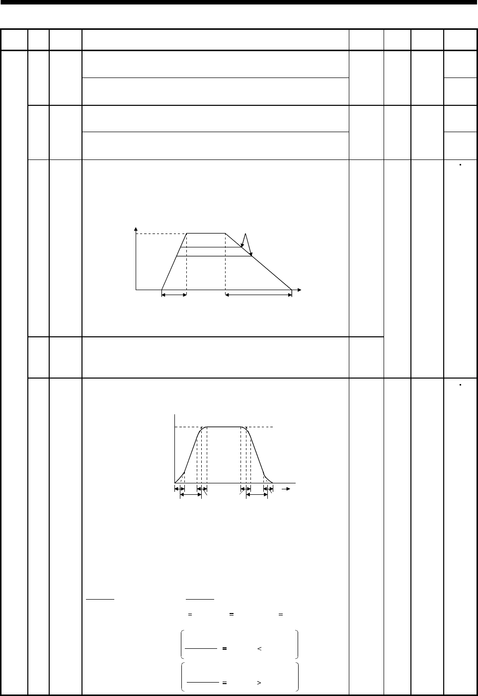
5 - 9
5. PARAMETERS
Class No. Symbol Name and function Initial
value Unit Setting
range
Control
mode
Internal speed command 2
Used to set speed 2 of internal speed commands.
S9SC2
Internal speed limit 2
Used to set speed 2 of internal speed limits.
500 r/min 0 to
instan-
taneous
permi-
ssible
speed
T
Internal speed command 3
Used to set speed 3 of internal speed commands.
S10 SC3
Internal speed limit 3
Used to set speed 3 of internal speed limits.
1000 r/min 0 to
instan-
taneous
permi-
ssible
speed
T
11 STA Acceleration time constant
Used to set the acceleration time required to reach the rated speed
from 0r/min in response to the analog speed command and internal
speed commands 1 to 7.
Tim
e
Parameter
No.12 setting
Parameter
No.11 setting
Zero
speed
Rated
speed
Speed
If the preset speed command is
lower than the rated speed,
acceleration/deceleration time
will be shorter.
For example for the servo motor of 3000r/min rated speed, set 3000
(3s) to increase speed from 0r/min to 1000r/min in 1 second.
0
12 STB Deceleration time constant
Used to set the deceleration time required to reach 0r/min from the
rated speed in response to the analog speed command and internal
speed commands 1 to 7.
0
ms 0
to
20000
ST
Basic parameters
13 STC S-pattern acceleration/deceleration time constant
Used to smooth start/stop of the servo motor.
Set the time of the arc part for S-pattern acceleration/deceleration.
STA: Acceleration time constant (parameter No.11)
STB: Deceleration time constant (parameter No.12)
STC: S-pattern acceleration/deceleration time con-
stant (parameter No.13)
Speed command
Servo motor
Speed
0r/min
STCSTA STC STC STB STC
Time
Long setting of STA (acceleration time constant) or STB (deceleration time
constant) may produce an error in the time of the arc part for the setting of the
S-pattern acceleration/deceleration time constant.
The upper limit value of the actual arc part time is limited by
At the setting of STA 20000, STB 5000 and STC 200,
the actual arc part times are as follows:
for acceleration or by for deceleration.
(Example)
During acceleration: 100[ms] 2000000
20000 100[ms] 200[ms].
Limited to 100[ms] since
During deceleration: 200[ms] 2000000
5000 400[ms] 200[ms].
200[ms] as set since
2000000
STA
2000000
STB
0ms0
to
1000
ST
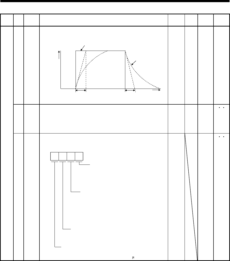
5 - 10
5. PARAMETERS
Class No. Symbol Name and function Initial
value Unit Setting
range
Control
mode
14 TQC Torque command time constant
Used to set the constant of a low pass filter in response to the torque
command.
Torque command
TQC TQC Time
After
filtered
TQC: Torque command time constant
Torque
0ms0
to
20000
T
15 *SNO Station number setting
Used to specify the station number for serial communication.
Always set one station to one axis of servo amplifier. If one station
number is set to two or more stations, normal communication cannot
be made.
0sta-
tion
0
to
31
PS T
Basic parameters
16 *BPS Serial communication function selection, alarm history clear
Used to select the serial communication baudrate, select various
communication conditions, and clear the alarm history.
Serial baudrate selection
0: 9600 [bps]
1: 19200[bps]
2: 38400[bps]
3: 57600[bps]
Alarm history clear
0: Invalid
1: Valid
When alarm history clear is made valid,
the alarm history is cleared at next power-on.
After the alarm history is cleared, the setting
is automatically made invalid (reset to 0).
Serial communication standard selection
0: RS-232C used
1: RS-422 used
Serial communication response delay time
0: Invalid
1: Valid, reply sent after delay time of 800 s or more
0000 Refer to
Name
and
function
column.
P S T
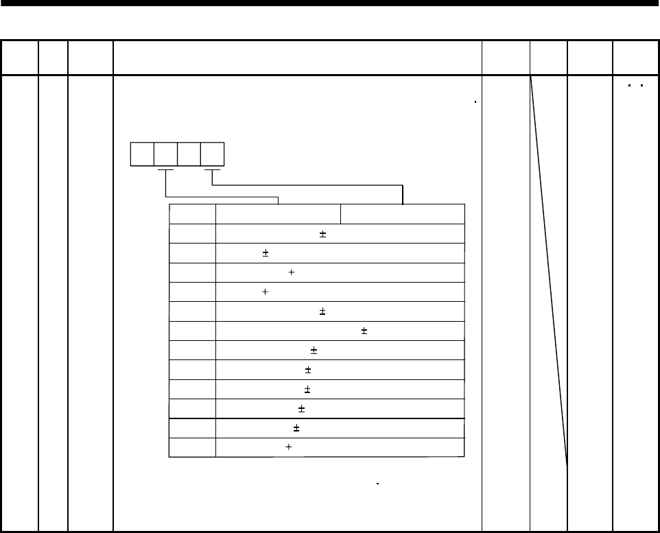
5 - 11
5. PARAMETERS
Class No. Symbol Name and function Initial
value Unit Setting
range
Control
mode
Basic parameters
17 MOD Analog monitor output
Used to selection the signal provided to the analog monitor (MO1)
analog monitor (MO2) output.
(Refer to Section 5.2.2)
Setting
0
Analog monitor (MO2)
Servo motor speed ( 8V/max. speed)
1 Torque ( 8V/max. torque) (Note)
2 Motor speed ( 8V/max. speed)
3 Torque ( 8V/max. torque) (Note)
4 Current command ( 8V/max. current command)
5 Command pulse frequency ( 10V/500kpulse/s)
6 Droop pulses ( 10V/128 pulses)
7 Droop pulses ( 10V/2048 pulses)
8 Droop pulses ( 10V/8192 pulses)
9 Droop pulses ( 10V/32768 pulses)
A Droop pulses ( 10V/131072 pulses)
00
B Bus voltage ( 8V/400V)
Analog monitor (MO1)
Note. 8V is outputted at the maximum torque.
However, when parameter No.28 76 are
set to limit torque, 8V is outputted at the
torque highly limited.
0100 Refer to
Name
and
function
column.
P S T
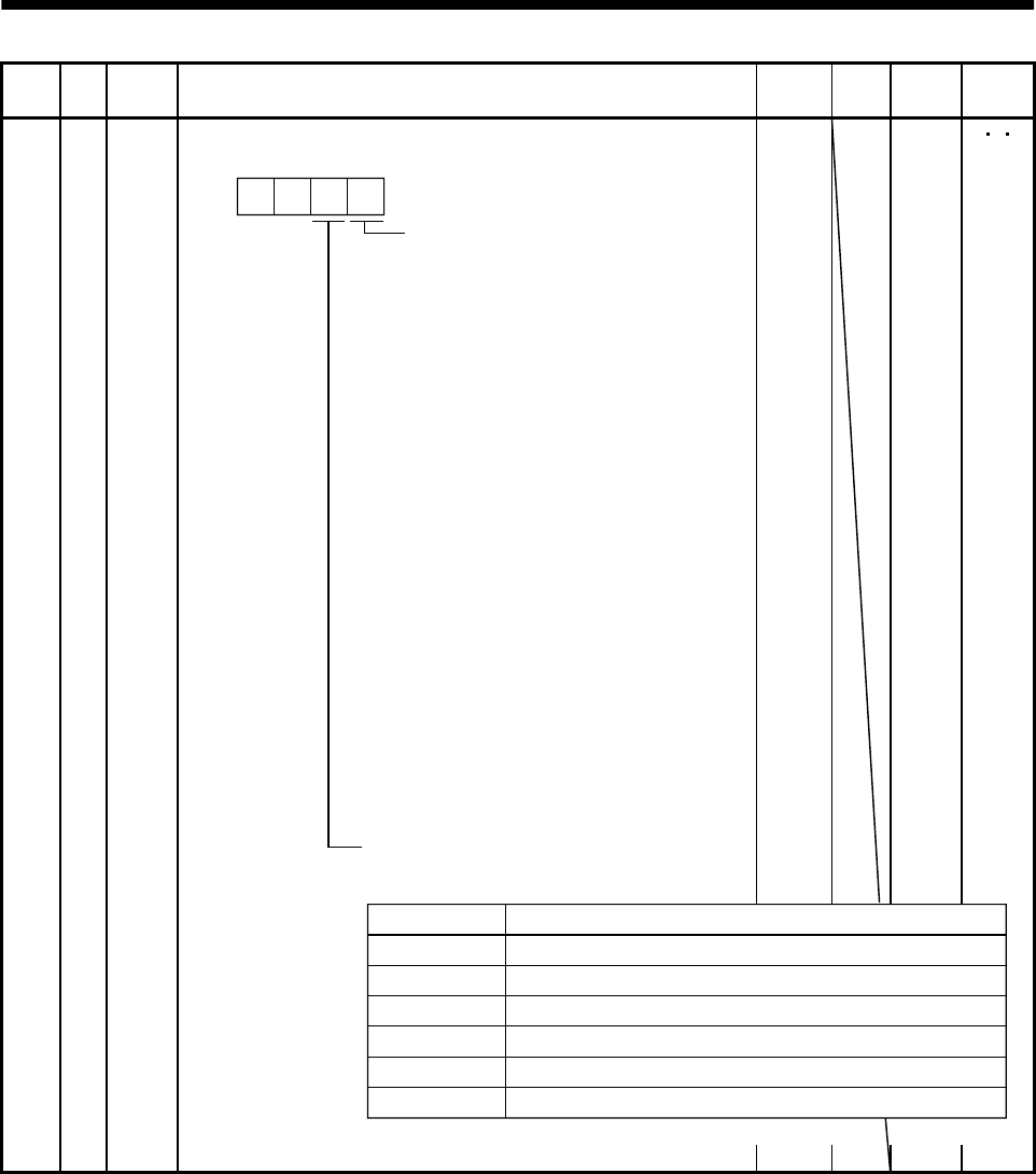
5 - 12
5. PARAMETERS
Class No. Symbol Name and function Initial
value Unit Setting
range
Control
mode
18 *DMD Status display selection
Used to select the status display shown at power-on.
Selection of status display at
power-on
0: Cumulative feedback pulses
1: Servo motor speed
2: Droop pulses
3: Cumulative command pulses
4: Command pulse frequency
5: Analog speed command voltage
(Note 1)
6: Analog torque command voltage
(Note 2)
7: Regenerative load ratio
8: Effective load ratio
9: Peak load ratio
A: Instantaneous torque
B: Within one-revolution position low
C: Within one-revolution position high
D: ABS counter
E: Load inertia moment ratio
F: Bus voltage
In speed control mode. Analog
speed limit voltage in torque
control mode.
In torque control mode. Analog
torque limit voltage in speed or
position control mode.
Note 1.
2.
Status display at power-on in
corresponding control mode
0: Depends on the control mode.
0 0
0000 Refer to
Name
and
function
column.
P S T
Control Mode
Position
Position/speed
Speed
Speed/torque
Torque
Torque/position
Status display at power-on
Cumulative feedback pulses
Cumulative feedback pulses/servo motor speed
Servo motor speed
Servo motor speed/analog torque command voltage
Analog torque command voltage
Analog torque command voltage/cumulative feedback pulses
1: Depends on the first digit setting of this parameter.
Basic parameters
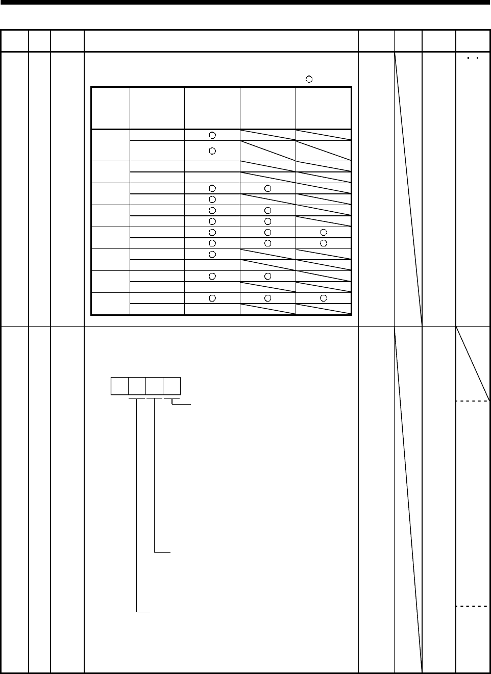
5 - 13
5. PARAMETERS
Class No. Symbol Name and function Initial
value Unit Setting
range
Control
mode
Parameter write inhibit
Used to select the reference and write ranges of the parameters.
Operation can be performed for the parameters marked .
Set
value Operation
Basic
parameters
No. 0
to No. 19
Expansion
parameters 1
No. 20
to No. 49
Expansion
parameters 2
No. 50
to No. 84
Reference0000
(Initial
value) Write
Reference No. 19 only
000A Write No. 19 only
Reference
000B Write
Reference
000C Write
Reference
000E Write
Reference
100B Write No. 19 only
Reference
100C Write No. 19 only
Reference
100E Write No. 19 only
Basic parameters
19 *BLK 0000 Refer to
Name
and
function
column.
P S T
20 *OP2 0000 Refer to
Name
and
function
column.
S
Expansion parameters 1
Function selection 2
Used to select restart after instantaneous power failure,
servo lock at a stop in speed control mode, and slight vibration
suppression control.
0: Invalid (Undervoltage alarm
(AL.10) occurs.)
1: Valid
If the power supply voltage has
returned to normal after an
undervoltage status caused by the
reduction of the input power supply
voltage in the speed control mode,
the servo motor can be restarted
by merely turning on the start signal
without resetting the alarm.
Restart after instantaneous power
failure
Stop-time servo lock selection
The shaft can be servo-locked to remain
still at a stop in the speed control mode.
0: Valid
1: Invalid
Slight vibration suppression control
Made valid when auto tuning selection is set to
"0400" in parameter No. 2.
Used to suppress vibration at a stop.
0: Invalid
1: Valid
0
P
5 - 14
5. PARAMETERS
Class No. Symbol Name and function Initial
value Unit Setting
range
Control
mode
21 *OP3 Function selection 3 (Command pulse selection)
Used to select the input form of the pulse train input signal.
(Refer to Section 3.4.1.)
Command pulse train input form
0: Forward/reverse rotation pulse train
1: Signed pulse train
2: A/B phase pulse train
Pulse train logic selection
0: Positive logic
1: Negative logic
0 0
0000 Refer to
Name
and
function
column.
P
22 *OP4 0000
P S
Expansion parameters 1
Function selection 4
Used to select stop processing at forward rotation stroke end (LSP)
reverse rotation stroke end (LSN) off and choose VC/VLA voltage
averaging.
How to make a stop when forward
rotation stroke end (LSP)
reverse rotation stroke end (LSN)
is valid. (Refer to Section 5.2.3.)
0: Sudden stop
1: Slow stop
Set value
0
1
2
Filtering time [ms]
0
0.444
0.888
3 1.777
VC/VLA voltage averaging
Used to set the filtering time when the
analog speed command (VC) voltage
or analog speed limit (VLA) is imported.
Set 0 to vary the speed to voltage fluctua-
tion in real time. Increase the set value
to vary the speed slower to voltage flu-
ctuation.
4 3.555
0 0
Refer to
Name
and
function
column.
P S T
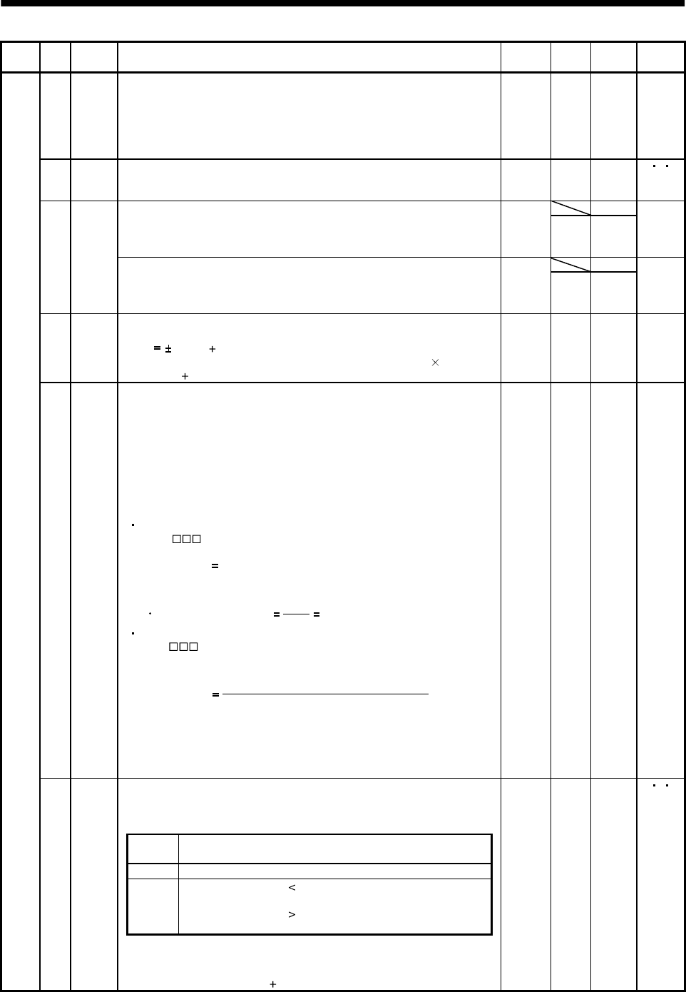
5 - 15
5. PARAMETERS
Class No. Symbol Name and function Initial
value Unit Setting
range
Control
mode
23 FFC Feed forward gain
Set the feed forward gain. When the setting is 100%, the droop pulses
during operation at constant speed are nearly zero. However, sudden
acceleration/deceleration will increase the overshoot. As a guideline,
when the feed forward gain setting is 100%, set 1s or more as the
acceleration/deceleration time constant up to the rated speed.
0%0
to
100
P
24 ZSP Zero speed
Used to set the output range of the zero speed (ZSP).
50 r/min 0
to
10000
P S T
0Analog speed command maximum speed
Used to set the speed at the maximum input voltage (10V) of the
analog speed command (VC).
Set "0" to select the rated speed of the servo motor connected.
0
r/min 1
to
50000
S
0
25 VCM
Analog speed limit maximum speed
Used to set the speed at the maximum input voltage (10V) of the
analog speed limit (VLA).
Set "0" to select the rated speed of the servo motor connected.
0
r/min 1
to
50000
T
26 TLC Analog torque command maximum output
Used to set the output torque at the analog torque command voltage
(TC 8V) of 8V on the assumption that the maximum torque is
100[%]. For example, set 50 to output (maximum torque 50/100) at
the TC of 8V.
100 % 0
to
1000
T
27 *ENR Encoder output pulses
Used to set the encoder pulses (A-phase, B-phase) output by the
servo amplifier.
Set the value 4 times greater than the A-phase or B-phase pulses.
You can use parameter No. 54 to choose the output pulse setting or
output division ratio setting.
The number of A/B-phase pulses actually output is 1/4 times greater
than the preset number of pulses.
The maximum output frequency is 1.3Mpps (after multiplication by
4). Use this parameter within this range.
For output pulse designation
Set " 0 " (initial value) in parameter No. 54.
Set the number of pulses per servo motor revolution.
Output pulse set value [pulses/rev]
At the setting of 5600, for example, the actually output A/B-phase
pulses are as indicated below:
4
5600
A B-phase output pulses 1400[pulse]
For output division ratio setting
Set " 1 " in parameter No. 54.
The number of pulses per servo motor revolution is divided by the
set value.
Output pulse [pulses/rev]
Resolution per servo motor revolution
Set value
At the setting of 8, for example, the actually output A/B-phase
pulses are as indicated below:
15
Ć
Č
ĆĆ
Ć15Ć
15
Internal torque limit 1
Set this parameter to limit servo motor torque on the assumption
that the maximum torque is 100[%].
When 0 is set, torque is not produced.
(Note)
TL Torque limit
0 Internal torque limit 1 (Parameter No. 28)
1 Analog torque limit internal torque limit 1
: Analog torque limit
Analog torque limit internal torque limit 1
: Internal torque limit 1
Expansion parameters 1
28 TL1
Note. 0: off
1: on
When torque is output in analog monitor output, this set value is the
maximum output voltage ( 8V). (Refer to Section 3.4.1, (5))
100 % 0
to
100
PS T

5 - 16
5. PARAMETERS
Class No. Symbol Name and function Initial
value Unit Setting
range
Control
mode
Analog speed command offset
Used to set the offset voltage of the analog speed command (VC).
For example, if CCW rotation is provided by switching on forward
rotation start (ST1) with 0V applied to VC, set a negative value.
When automatic VC offset is used, the automatically offset value is
set to this parameter. (Refer to Section6.3.)
The initial value is the value provided by the automatic VC offset
function before shipment at the VC-LG voltage of 0V.
S
29 VCO
Analog speed limit offset
Used to set the offset voltage of the analog speed limit (VLA).
For example, if CCW rotation is provided by switching on forward
rotation selection (RS1) with 0V applied to VLA, set a negative value.
When automatic VC offset is used, the automatically offset value is
set to this parameter. (Refer to Section6.3.)
The initial value is the value provided by the automatic VC offset
function before shipment at the VLA-LG voltage of 0V.
Depends
on servo
amplifier
mV 999
to
999
T
Analog torque command offset
Used to set the offset voltage of the analog torque command (TC).
T30 TLO
Analog torque limit offset
Used to set the offset voltage of the analog torque limit (TLA).
0mV999
to
999 S
31 MO1 Analog monitor 1 offset
Used to set the offset voltage of the analog monitor (MO1).
0mV 999
to 999 PS T
32 MO2 Analog monitor 2 offset
Used to set the offset voltage of the analog monitor (MO2).
0mV 999
to 999 PS T
33 MBR Electromagnetic brake sequence output
Used to set the delay time (Tb) between electronic brake interlock
(MBR) and the base drive circuit is shut-off.
100 ms 0
to
1000
PS T
34 GD2 Ratio of load inertia moment to servo motor inertia moment
Used to set the ratio of the load inertia moment to the servo motor
shaft inertia moment. When auto tuning mode 1 and interpolation
mode is selected, the result of auto tuning is automatically used.
(Refer to section 7.1.1)
In this case, it varies between 0 and 1000.
70 0.1
times
0
to
3000
PS
35 PG2 Position loop gain 2
Used to set the gain of the position loop.
Set this parameter to increase the position response to level load
disturbance. Higher setting increases the response level but is liable
to generate vibration and/or noise.
When auto tuning mode 1,2 and interpolation mode is selected, the
result of auto tuning is automatically used.
7kW or
less: 35
11kW or
more: 19
rad/s 1
to
1000
P
36 VG1 Speed loop gain 1
Normally this parameter setting need not be changed.
Higher setting increases the response level but is liable to generate
vibration and/or noise.
When auto tuning mode 1 2, manual mode and interpolation mode
is selected, the result of auto tuning is automatically used.
7kW or
less: 177
11kW or
more: 96
rad/s 20
to
8000
PS
37 VG2 Speed loop gain 2
Set this parameter when vibration occurs on machines of low rigidity
or large backlash. Higher setting increases the response level but is
liable to generate vibration and/or noise.
When auto tuning mode 1 2 and interpolation mode is selected, the
result of auto tuning is automatically used.
7kW or
less: 817
11kW or
more: 45
rad/s 20
to
20000
PS
Expansion parameters 1
38 VIC Speed integral compensation
Used to set the integral time constant of the speed loop.
Lower setting increases the response level but is liable to generate
vibration and/or noise.
When auto tuning mode 1 2 and interpolation mode is selected, the
result of auto tuning is automatically used.
7kW or
less: 48
11kW or
more: 91
ms 1
to
1000
PS
5 - 17
5. PARAMETERS
Class No. Symbol Name and function Initial
value Unit Setting
range
Control
mode
39 VDC Speed differential compensation
Used to set the differential compensation.
Made valid when the proportion control (PC) is switched on.
980 0
to
1000
PS
40 For manufacturer setting
Do not change this value by any means.
0
P S T41 *DIA Input signal automatic ON selection
Used to set automatic Servo-on (SON) forward rotation stroke end
(LSP) reveres rotation stroke end (LSN).
Servo-on (SON) input selection
0: Switched on/off by external input.
1: Switched on automatically in servo
amplifier.
(No need of external wiring)
0: Switched on/off by external input.
1: Switched on automatically in servo
amplifier.
(No need of external wiring)
0: Switched on/off by external input.
1: Switched on automatically in servo
amplifier.
(No need of external wiring)
Reverse rotation stroke end (LSN)
input selection
Forward rotation stroke end
(LSP) input selection
0
0000 Refer to
Name
and
function
column.
P S
P/S
S/T
T/P
Expansion parameters 1
42 *DI1 Input signal selection 1
Used to assign the control mode changing signal input pins and to set
the clear (CR).
Control change (LOP) in-
put pin assignment
Used to set the control mode
change signal input connector
pins. Note that this parameter is
made valid when parameter No.
0 is set to select the position/spe-
ed, speed/torque or torque/posi-
tion change mode.
Set value
0
1
2
Connector pin No.
CN1B-5
CN1B-14
CN1A-8
3CN1B-7
Clear (CR) selection
0: Droop pulses are cleared on the
leading edge.
1: While on, droop pulses are always cleared.
4CN1B-8
5CN1B-9
0 0
0003 Refer to
Name
and
function
column.
P S T
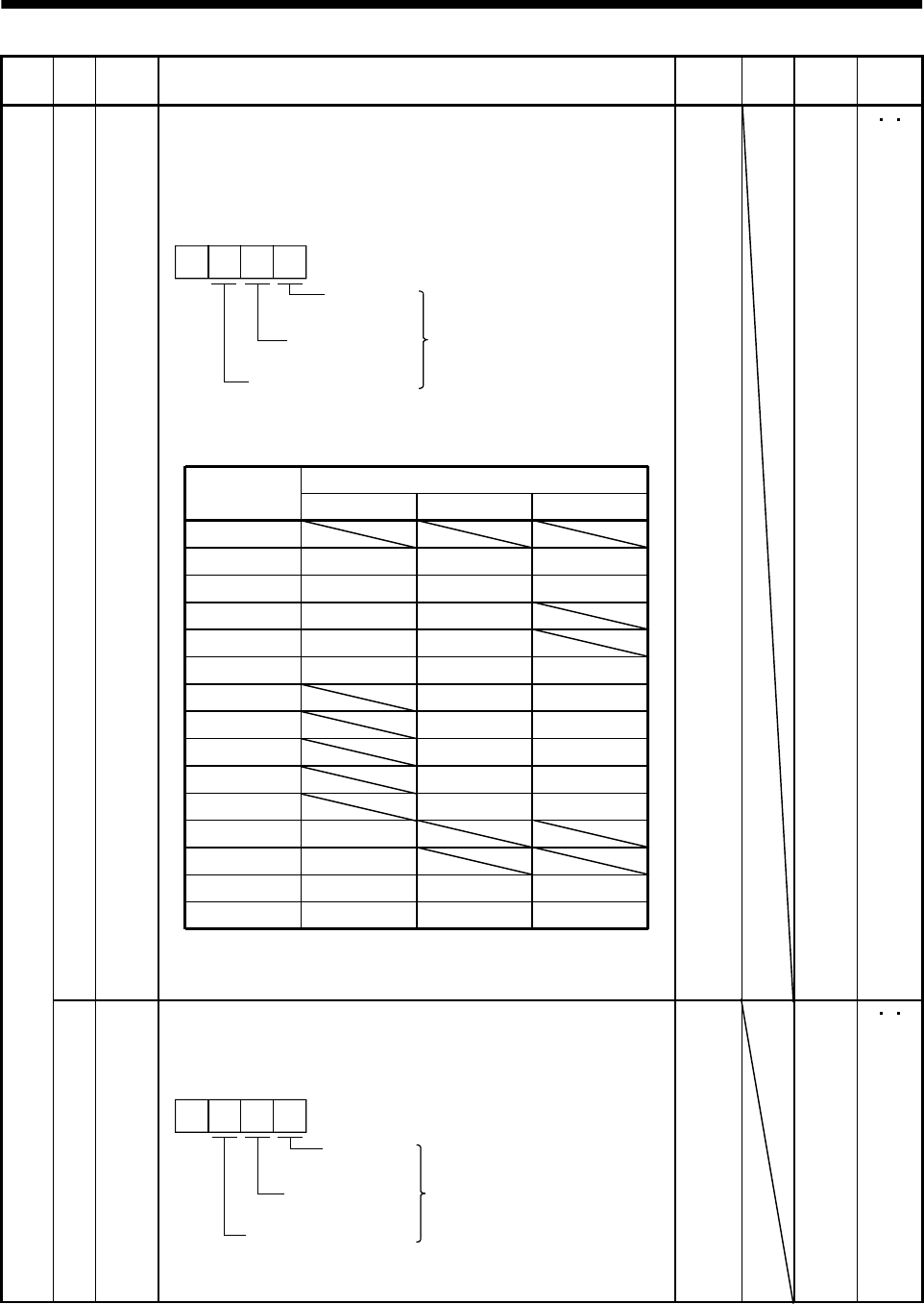
5 - 18
5. PARAMETERS
Class No. Symbol Name and function Initial
value Unit Setting
range
Control
mode
43 *DI2 Input signal selection 2 (CN1B-5)
This parameter is unavailable when parameter No.42 is set to assign
the control change (LOP) to CN1B-pin 5.
Allows any input signal to be assigned to CN1B-pin 5.
Note that the setting digit and assigned signal differ according to the
control mode.
Position
control mode Input signals of
CN1B-pin 5
selected.
Torque control mode
Speed control
mode
0
Signals that may be assigned in each control mode are indicated
below by their symbols.
Setting of any other signal will be invalid.
Set value (Note) Control mode
PST
0
1
2
3
4
5
6
7
8
9
SON SON SON
RES RES RES
PC PC
TL TL
SP1 SP1
SP2 SP2
ST1 RS2
ST2 RS1
CR CR CR
ASP3 SP3
B
C
DTL1 TL1
ECDP CDP
CM1
CM2
TL1
CDP
Note. P: Position control mode
S: Speed control mode
T: Torque control mode
0111 Refer to
Name
and
function
column.
P S T
Expansion parameters 1
44 *DI3 Input signal selection 3 (CN1B-14)
Allows any input signal to be assigned to CN1B-pin 14.
The assignable signals and setting method are the same as in input
signal selection 2 (parameter No. 43).
Position
control mode Input signals of
CN1B-pin 14
selected.
Torque control mode
Speed control
mode
0
This parameter is unavailable when parameter No. 42 is set to
assign the control change (LOP) to CN1B-pin 14.
0222 Refer to
Name
and
function
column.
P S T
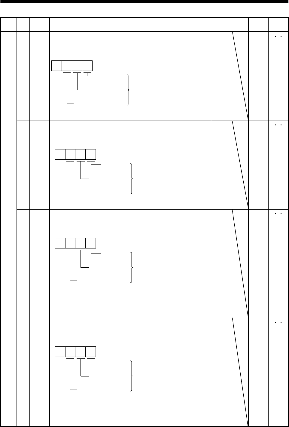
5 - 19
5. PARAMETERS
Class No. Symbol Name and function Initial
value Unit Setting
range
Control
mode
45 *DI4 Input signal selection 4 (CN1A-8)
Allows any input signal to be assigned to CN1A-pin 8.
The assignable signals and setting method are the same as in input
signal selection 2 (parameter No. 43).
Position
control mode Input signals of
CN1A-pin 8
selected.
Torque control mode
Speed control
mode
0
This parameter is unavailable when parameter No. 42 is set to
assign the control change (LOP) to CN1 A-pin 8.
0665 Refer to
Name
and
function
column.
P S T
46 *DI5 Input signal selection 5 (CN1B-7)
Allows any input signal to be assigned to CN1B-pin 7.
The assignable signals and setting method are the same as in input
signal selection 2 (parameter No. 43).
Position
control mode Input signals of
CN1B-pin 7
selected.
Tor
q
ue control mode
Speed control
mode
0
This parameter is unavailable when parameter No. 42 is set to
assign the control change (LOP) to CN1 B-pin 7.
0770 Refer to
Name
and
function
column.
P S T
47 *DI6 Input signal selection 6 (CN1B-8)
Allows any input signal to be assigned to CN1B-pin 8.
The assignable signals and setting method are the same as in input
signal selection 2 (parameter No. 43).
Position
control mode Input signals of
CN1B-pin 8
selected.
Tor
q
ue control mode
Speed control
mode
0
This parameter is unavailable when parameter No. 42 is set to
assign the control change (LOP) to CN1B-pin 8.
When "Used in absolute position detection system" is selected in
parameter No. 1, CN1B-pin 8 is in the ABS transfer mode (ABSM).
(Refer to Section 15.5.)
0883 Refer to
Name
and
function
column.
P S T
Expansion parameters 1
48 *DI7 Input signal selection 7 (CN1B-9)
Allows any input signal to be assigned to CN1B-pin 9.
The assignable signals and setting method are the same as in input
signal selection 2 (parameter No. 43).
Position
control mode Input signals of
CN1B-pin 9
selected.
Tor
q
ue control mode
Speed control
mode
0
This parameter is unavailable when parameter No. 42 is set to
assign the control change (LOP) to CN1B-pin 9.
When "Used in absolute position detection system" is selected in
parameter No. 1, CN1B-pin 9 is in the ABS request mode (ABSR).
(Refer to Section 15.5.)
0994 Refer to
Name
and
function
column.
P S T
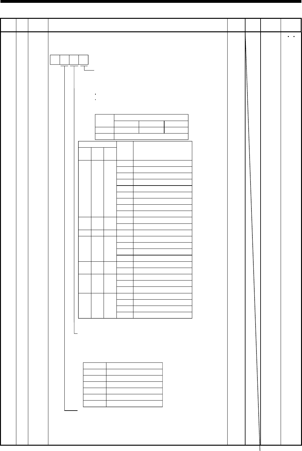
5 - 20
5. PARAMETERS
Class No. Symbol Name and function Initial
value Unit Setting
range
Control
mode
Expansion parameters 1
49 *DO1 Output signal selection 1
Used to select the connector pins to output the alarm code, warning
(WNG) and battery warning (BWNG).
Setting of alarm code output
Connector pins
Set value CN1B-19 CN1A-18 CN1A-19
0ZSP INP or SA RD
1
88888
AL.12
AL.13
AL.15
AL.17
AL.8A
AL.8E
AL.30
AL.45
AL.50
AL.51
AL.24
AL.32
AL.31
AL.35
AL.52
AL.16
AL.20
Name
Watchdog
Memory error 1
Clock error
Memory error 2
Board error 2
Serial communication time-out error
Serial communication error
Regenerative error
Main circuit device overheat
Overload 1
Overload 2
Main circuit
Overcurrent
Overspeed
Command pulse frequency error
Error excessive
Encoder error 1
Encoder error 2
Alarm
display
(Note) Alarm code
CN1B
pin 19
0
000
1
CN1A
pin 18
001
1
01
CN1A
pin 19
1
1
0
1
0
10
Set value Connector pin No.
Note. 0: off
1: on
Setting of warning (WNG) output
Select the connector pin to output warning. The old signal
before selection will be unavailable. A parameter error
(AL. 27) will occur if the connector pin setting is the same
as that in the third digit.
AL.19 Memory error 3
AL.37 Parameter error
AL.33 Overvoltage
AL.46 Servo motor overheat
AL.10 Undervoltage100
AL.1A
AL.25
Motor combination error
Absolute position erase
Setting of battery warning (BWNG) output
Select the connector pin to output battery warning. The old
signal before selection will be unavailable. Set this function
as in the second digit of this parameter. Parameter No. 1
setting has priority. A parameter error (AL. 37) will occur if the
connector pin setting is the same as that in the second digit.
0Not output.
1CN1A-19
2CN1B-18
3CN1A-18
4CN1B-19
5CN1B-6
0
Alarm code is output at alarm occurrence.
The alarm code output and the following functions
are exclusive, so the simultaneous use is not possible.
If set, the parameter error alarm (AL.37) occurs.
Absolute position detection system
Signal assignment function of the electromagnetic
interlock (MBR) to pin CN1B-19
0000 Refer to
Name
and
function
column.
P S T
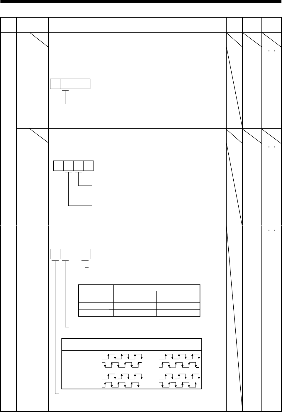
5 - 21
5. PARAMETERS
Class No. Symbol Name and function Initial
value Unit Setting
range
Control
mode
50 For manufacturer setting
Do not change this value by any means.
0000
51 *OP6 Function selection 6
Used to select the operation to be performed when the reset (RES)
switches on. This parameter is invalid (base circuit is shut off) in the
absolute position detection system.
000
Operation to be performed when the
reset (RES) switches on
0: Base circuit shut off
1: Base circuit not shut off
0000 Refer to
Name
and
function
column.
P S T
52 For manufacturer setting
Do not change this value by any means.
0000
53 *OP8 Function selection 8
Used to select the protocol of serial communication.
0 0
Protocol checksum selection
0: Yes (checksum added)
1: No (checksum not added)
Protocol checksum selection
0: With station numbers
1: No station numbers
0000 Refer to
Name
and
function
column.
P S T
Expansion parameters 2
54 *OP9 Function selection 9
Use to select the command pulse rotation direction, encoder output
pulse direction and encoder pulse output setting.
0
0
1
CCW
CW
CW
CCW
Servo motor rotation direction changing
Changes the servo motor rotation
direction for the input pulse train.
Set value
Servo motor rotation direction
At forward rotation
pulse input (Note)
At reverse rotation
pulse input (Note)
Note. Refer to Section 3.4.1, (1), (a).
Encoder pulse output phase changing
Changes the phases of A, B-phase encoder pulses output .
Encoder output pulse setting selection (refer to parameter No. 27)
0: Output pulse designation
1: Division ratio setting
Servo motor rotation direction
Set value CCW CW
0
1
A phase
B phase
A phase
B phase
A phase
B phase
A phase
B phase
0000 Refer to
Name
and
function
column.
P S T
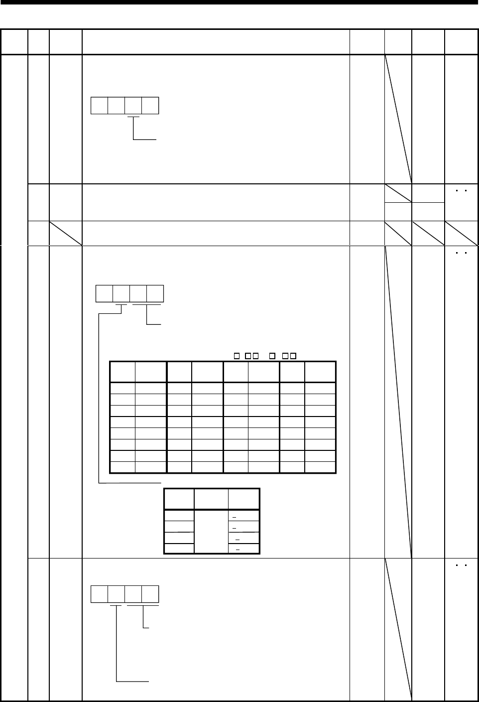
5 - 22
5. PARAMETERS
Class No. Symbol Name and function Initial
value Unit Setting
range
Control
mode
55 *OPA Function selection A
Used to select the position command acceleration/deceleration time
constant (parameter No. 7) control system.
000
0: Primary delay
1: Linear acceleration/deceleration
Position command acceleration/deceleration
time constant control
0000 Refer to
Name
and
function
column.
P
0
56 SIC Serial communication time-out selection
Used to set the communication protocol time-out period in [s].
When you set "0", time-out check is not made.
0
s1 to 60
PS T
57 For manufacturer setting
Do not change this value by any means.
10
58 NH1 Machine resonance suppression filter 1
Used to selection the machine resonance suppression filter.
(Refer to Section 8.1.)
2
3
0
0
1
40dB
14dB
8dB
4dB
Notch frequency selection
Set "00" when you have set adaptive vibration
suppression control to be "valid" or "held"
(parameter No. 60: 1 or 2 ).
00
01
02
03
04
05
06
07
Setting
value
Frequency
Invalid
4500
2250
1500
1125
900
750
642.9
08
09
0A
0B
0C
0D
0E
0F
562.5
500
450
409.1
375
346.2
321.4
300
Frequency
10
11
12
13
14
15
16
17
281.3
264.7
250
236.8
225
214.3
204.5
195.7
Frequency
18
19
1A
1B
1C
1D
1E
1F
187.5
180
173.1
166.7
160.1
155.2
150
145.2
Frequency
Notch depth selection
Setting
value
Depth Gain
Deep
Shallow
to
Setting
value
Setting
value
Setting
value
0000 Refer to
Name
and
function
column.
P S T
Expansion parameters 2
59 NH2 Machine resonance suppression filter 2
Used to set the machine resonance suppression filter.
0
Notch frequency
Same setting as in parameter No. 58
However, you need not set "00" if you have
set adaptive vibration suppression control to
be "valid" or "held".
Notch depth
Same setting as in parameter No. 58
0000 Refer to
Name
and
function
column.
P S T
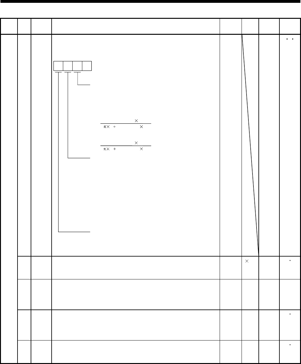
5 - 23
5. PARAMETERS
Class No. Symbol Name and function Initial
value Unit Setting
range
Control
mode
60 LPF Low-pass filter/adaptive vibration suppression control
Used to selection the low-pass filter and adaptive vibration
suppression control. (Refer to Chapter 8.)
0
Low-pass filter selection
0: Valid (Automatic adjustment)
1: Invalid
Adaptive vibration suppression control selection
Choosing "valid" or "held" in adaptive vibration
suppression control selection makes the machine
resonance control filter 1 (parameter No. 58) invalid.
0: Invalid
1: Valid
Machine resonance frequency is always detected
and the filter is generated in response to resonance to
suppress machine vibration.
2: Held
The characteristics of the filter generated so far are held,
and detection of machine resonance is stopped.
Adaptive vibration suppression control sensitivity selection
Used to set the sensitivity of machine resonance detection.
0: Normal
1: Large sensitivity
When you choose "vaid", the filter of the handwidth
represented by the following expression is set automatically.
2 (1 GD2 setting 0.1)
VG2 setting 10
For 1kW or less
2 (1 GD2 setting 0.1)
VG2 setting 5
For 2kW or more
[Hz]
[Hz]
0000 Refer to
Name
and
function
column.
P S T
61 GD2B Ratio of load inertia moment to servo motor inertia moment 2
Used to set the ratio of load inertia moment to servo motor inertia
moment when gain changing is valid.
70 0.1
times
0
to
3000
PS
62 PG2B Position control gain 2 changing ratio
Used to set the ratio of changing the position control gain 2 when
gain changing is valid.
Made valid when auto tuning is invalid.
100 % 10
to
200
P
63 VG2B Speed control gain 2 changing ratio
Used to set the ratio of changing the speed control gain 2 when gain
changing is valid.
Made valid when auto tuning is invalid.
100 % 10
to
200
PS
Expansion parameters 2
64 VICB Speed integral compensation changing ratio
Used to set the ratio of changing the speed integral compensation
when gain changing is valid. Made valid when auto tuning is invalid.
100 % 50
to
1000
PS
5 - 24
5. PARAMETERS
Class No. Symbol Name and function Initial
value Unit Setting
range
Control
mode
65 *CDP Gain changing selection
Used to select the gain changing condition. (Refer to Section 8.3.)
000
Gain changing selection
Gains are changed in accordance with the settings
of parameters No. 61 to 64 under any of the following
conditions:
0: Invalid
1: Gain changing (CDP) signal is ON
2: Command frequency is equal to higher than
parameter No. 66 setting
3: Droop pulse value is equal to higher than
parameter No. 66 setting
4: Servo motor speed is equal to higher than
parameter No. 66 setting
0000 Refer to
Name
and
function
column.
P S
66 CDS Gain changing condition
Used to set the value of gain changing condition (command
frequency, droop pulses, servo motor speed) selected in parameter
No. 65.The set value unit changes with the changing condition item.
(Refer to Section 8.5.)
10 kpps
pulse
r/min
10
to
9999
PS
67 CDT Gain changing time constant
Used to set the time constant at which the gains will change in
response to the conditions set in parameters No. 65 and 66.
(Refer to Section 8.5.)
1ms0
to
100
PS
68 For manufacturer setting
Do not change this value by any means.
0
69 CMX2 Command pulse multiplying factor numerator 2
Used to set the multiplier for the command pulse.
Setting "0" automatically sets the connected motor resolution.
10
1
to
65535
P
70 CMX3 Command pulse multiplying factor numerator 3
Used to set the multiplier for the command pulse.
Setting "0" automatically sets the connected motor resolution.
10
1
to
65535
P
71 CMX4 Command pulse multiplying factor numerator 4
Used to set the multiplier for the command pulse.
Setting "0" automatically sets the connected motor resolution.
10
1
to
65535
P
Internal speed command 4
Used to set speed 4 of internal speed commands.
S
Expansion parameters 2
72 SC4
Internal speed limit 4
Used to set speed 4 of internal speed limits.
200 r/min 0 to in-
stanta-
neous
permi-
ssible
speed
T
5 - 25
5. PARAMETERS
Class No. Symbol Name and function Initial
value Unit Setting
range
Control
mode
Internal speed command 5
Used to set speed 5 of internal speed commands.
S73 SC5
Internal speed limit 5
Used to set speed 5 of internal speed limits.
300 r/min 0 to in-
stanta-
neous
permi-
ssible
speed
T
Internal speed command 6
Used to set speed 6 of internal speed commands.
S74 SC6
Internal speed limit 6
Used to set speed 6 of internal speed limits.
500 r/min 0 to in-
stanta-
neous
permi-
ssible
speed
T
Internal speed command 7
Used to set speed 7 of internal speed commands.
S75 SC7
Internal speed limit 7
Used to set speed 7 of internal speed limits.
800 r/min 0 to in-
stanta-
neous
permi-
ssible
speed
T
76 TL2 Internal torque limit 2
Set this parameter to limit servo motor torque on the assumption
that the maximum torque is 100[%].
When 0 is set, torque is not produced.
100 % 0
to
100
PS T
77 00
78 10000
79 10
80 10
81 100
82 100
83 100
Expansion parameters 2
84
For manufacturer setting
Do not change this value by any means.
0000
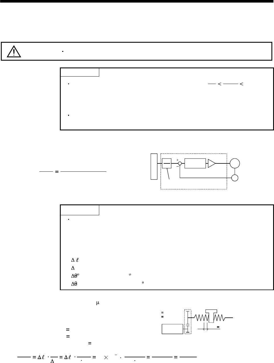
5 - 26
5. PARAMETERS
5.2 Detailed description
5.2.1 Electronic gear
CAUTION Wrong setting can lead to unexpected fast rotation, causing injury.
POINT
The guideline of the electronic gear setting range is 50
1
CDV
CMX 500.
If the set value is outside this range, noise may be generated during
acceleration/ deceleration or operation may not be performed at the preset
speed and/or acceleration/deceleration time constants.
The following specification symbols are required to calculate the electronic
gear.
(1) Concept of electronic gear
The machine can be moved at any multiplication factor to input pulses.
CDV
CMX
Parameter No.4
Parameter No.3
Electronic gear
Feedback pulse
CMX
CDV Deviation
counter
Motor
Encoder
Input pulse train
The following setting examples are used to explain how to calculate the electronic gear:
POINT
The following specification symbols are required to calculate the electronic
gear
Pb : Ballscrew lead [mm]
n : Reduction ratio
Pt : Servo motor resolution [pulses/rev]
0: Travel per command pulse [mm/pulse]
S: Travel per servo motor revolution [mm/rev]
: Angle per pulse [ /pulse]
: Angle per revolution [ /rev]
(a) For motion in increments of 10 m per pulse
Machine specifications
Ballscrew lead Pb 10 [mm]
Reduction ratio: n 1/2
Servo motor resolution: Pt 131072 [pulses/rev] Servo motor
131072 [pulse/rev]
n
NM
NL
Pb 10[mm]
n NL/NM
1/2
CDV
CMX 0Pt
S0Pt
nPb 10 10 3
1/2 10
131072 262144
1000
32768
125
Hence, set 32768 to CMX and 125 to CDV.
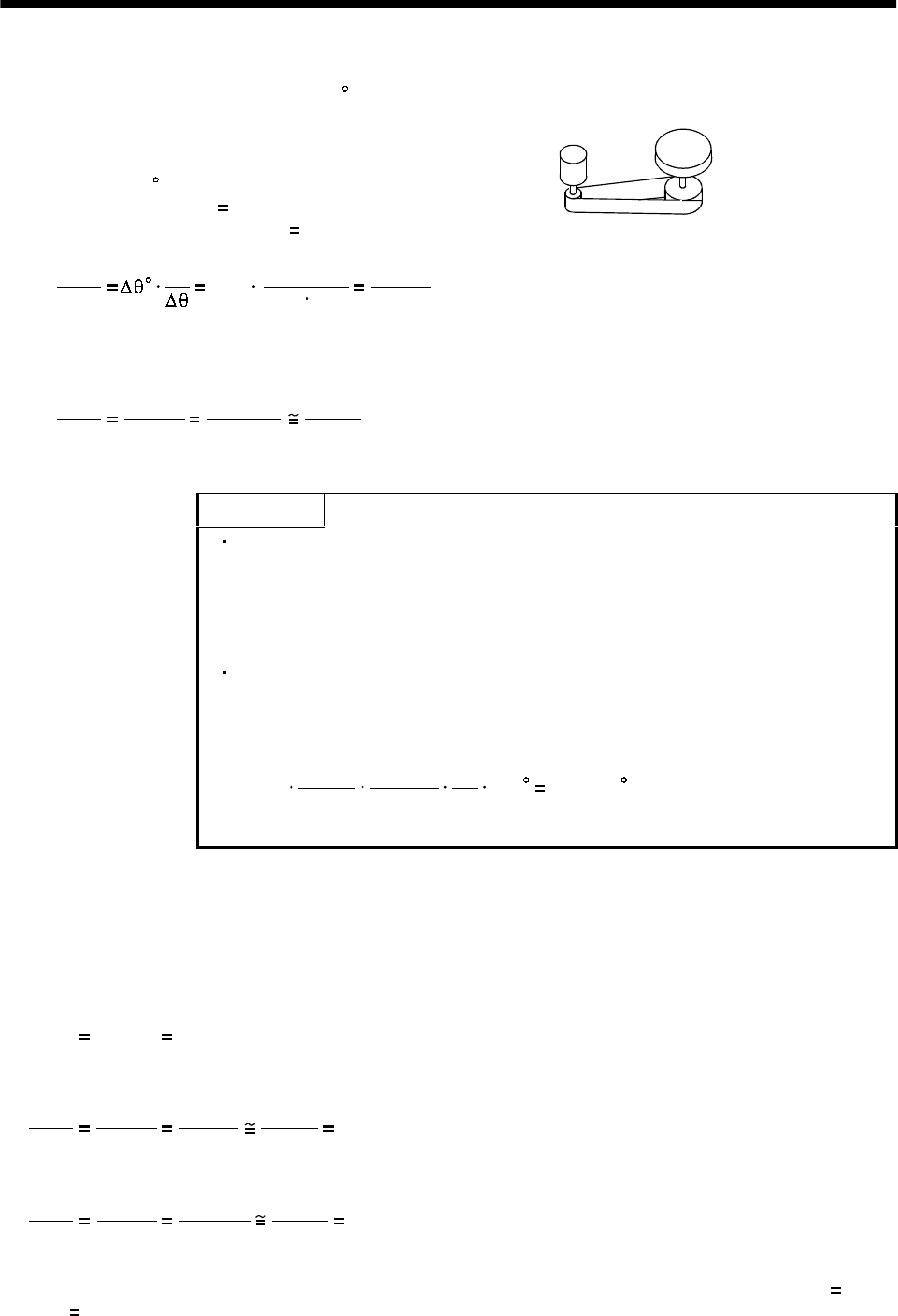
5 - 27
5. PARAMETERS
(b) Conveyor setting example
For rotation in increments of 0.01 per pulse
Machine specifications
Table : 360 /rev
Reduction ratio: n 4/64
Servo motor resolution: Pt 131072 [pulses/rev]
Table
Timing belt : 4/64
Servo motor
131072 [pulse/rev]
CDV
CMX Pt 131072 65536
1125
0.01 4/64 360 ................................................................................. (5.2)
Since CMX is not within the setting range in this status, it must be reduced to the lowest term.
When CMX has been reduced to a value within the setting range, round off the value to the
nearest unit.
CDV
CMX 65536
1125
26214.4
450
26214
450
Hence, set 26214 to CMX and 450 to CDV.
POINT
When “0” is set to parameter No.3 (CMX), CMX is automatically set to the
servo motor resolution. Therefore, in the case of Expression (5.2), setting
0 to CMX and 2250 to CDX concludes in the following expression:
CMX/CDV=131072/2250, and electric gear can be set without the
necessity to reduce the fraction to the lowest term.
For unlimited one-way rotation, e.g. an index table, indexing positions will
be missed due to cumulative error produced by rounding off.
For example, entering a command of 36000 pulses in the above example
causes the table to rotate only:
26214
450
36000 1
131072
4
64 360 359.995
Therefore, indexing cannot be done in the same position on the table.
(2) Instructions for reduction
The calculated value before reduction must be as near as possible to the calculated value after
reduction.
In the case of (1), (b) in this section, an error will be smaller if reduction is made to provide no fraction
for CDV. The fraction of Expression (5.1) before reduction is calculated as follows.
CDV
CMX 65536
1125 58.25422.................................................................................................................... (5.2)
The result of reduction to provide no fraction for CMX is as follows.
CDV
CMX 65536
1125
32768
562.5
32768
563 58.20249 .................................................................................... (5.3)
The result of reduction to provide no fraction for CDV is as follows.
CDV
CMX 65536
1125
26214.4
450
26214
450 58.25333.................................................................................. (5.4)
As a result, it is understood that the value nearer to the calculation result of Expression (5.2) is the
result of Expression (5.4). Accordingly, the set values of (1), (b) in this section are CMX 26214,
CDV 450.
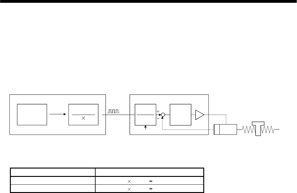
5 - 28
5. PARAMETERS
(3) Setting for use of A1SD75P
The A1SD75P also has the following electronic gear parameters. Normally, the servo amplifier side
electronic gear must also be set due to the restriction on the command pulse frequency (differential
400kpulse/s, open collector 200kpulse/s).
AP: Number of pulses per motor revolution
AL: Moving distance per motor revolution
AM: Unit scale factor
Command
value Control
unit
AP
AMAL
CMX
CDV
Deviation
counter
Electronic gear Feedback pulse
Command
pulse
Servo amplifierA1SD75P
Servo motor
Electronic gear
The resolution of the servo motor is 131072 pulses/rev. For example, the pulse command needed to
rotate the servo motor is as follows
Servo motor speed [r/min] Required pulse command
2000 131072 2000/60 4369066 pulse/s
3000 131072 3000/60 6553600 pulse/s
For the A1SD75P, the maximum value of the pulse command that may be output is 200kpulse/s in the
open collector system or 400kpulse/s in the differential line driver system. Hence, either of the servo
motor speeds exceeds the maximum output pulse command of the A1SD75P.
Use the electronic gear of the servo amplifier to run the servo motor under the maximum output pulse
command of the A1SD75P.
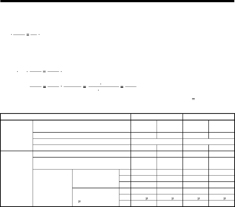
5 - 29
5. PARAMETERS
To rotate the servo motor at 3000r/min in the open collector system (200kpulse/s), set the electronic
gear as follows
CDV
CMX N0
f60 pt
f : Input pulses [pulse/s]
N0: Servo motor speed [r/min]
Pt : Servo motor resolution [pulse/rev]
200 CDV
CMX 3000
60 131072
CDV
CMX 3000
60
131072
200 60 200000
3000 131072 4096
125
10 3
The following table indicates the electronic gear setting example (ballscrew lead 10mm) when the
A1SD75P is used in this way.
Rated servo motor speed 3000r/min 2000r/min
Input system Open
collector
Differential
line driver
Open
collector
Differential
line driver
Max. input pulse frequency [kpulse/s] 200 500 200 500
Feedback pulse/revolution [pulse/rev] 131072 131072
Servo amplifier
Electronic gear (CMX/CDV) 4096/125 2048/125 8192/375 4096/375
Command pulse frequency [kpulse/s] (Note) 200 400 200 400
Number of pulses per servo motor revolution as
viewed from A1SD75P[pulse/rev] 4000 8000 6000 12000
AP1111
AL1111
Minimum command unit
1pulse AM1111
AP 4000 8000 6000 12000
AL 100.0[ m] 100.0[ m] 100.0[ m] 100.0[ m]
A1SD75P
Electronic gear
Minimum command unit
0.1 mAM 10 10 10 10
Note. Command pulse frequency at rated speed
5 - 30
5. PARAMETERS
5.2.2 Analog monitor
The servo status can be output to two channels in terms of voltage. The servo status can be monitored
using an ammeter.
(1) Setting
Change the following digits of parameter No.17:
Analog monitor (MO1) output selection
(Signal output to across MO1-LG)
Analog monitor (MO2) output selection
(Signal output to across MO2-LG)
Parameter No. 17
00
Parameters No.31 and 32 can be used to set the offset voltages to the analog output voltages. The setting
range is between 999 and 999mV.
Parameter No. Description Setting range [mV]
31 Used to set the offset voltage for the analog monitor 1 (MO1).
32 Used to set the offset voltage for the analog monitor 2 (MO2)
output.
999 to 999
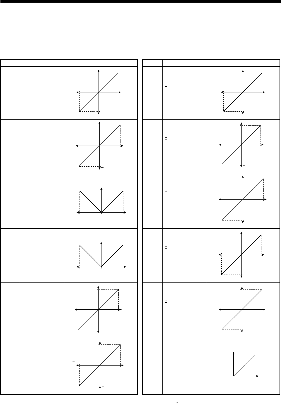
5 - 31
5. PARAMETERS
(2) Set content
The servo amplifier is factory-set to output the servo motor speed to analog monitor 1 (MO1) and the
torque to analog monitor (MO2). The setting can be changed as listed below by changing the
parameter No.17 value:
Refer to Appendix 2 for the measurement point.
Setting Output item Description Setting Output item Description
0Servo motor speed 8[V]
Max. speed
0Max. speed
8[V]
CCW direction
CW direction
6 Droop pulses
(Note1)
(10V/128pulse)
10[V]
0128[pulse]
10[V]
CCW direction
CW direction
128[pulse]
1 Torque(Note2) 8[V]
Max. torque
0Max. torque
8[V]
Drivin
g
in CW direction
Driving in CCW direction 7 Droop pulses
(Note1)
(10V/2048pulse)
10[V]
02048[pulse]
10[V]
CCW direction
CW direction
2048[pulse]
2Servo motor speed
8[V]
Max. speed 0Max. speed
CCW
direction
CW
direction
8 Droop pulses
(Note1)
(10V/8192pulse)
10[V]
08192[pulse]
10[V]
CCW direction
CW direction
8192[pulse]
3 Torque(Note2)
8[V]
Max. torque 0Max. torque
Driving in
CW direction Driving in
CCW direction
9 Droop pulses
(Note1)
(10V/32768pulse)
10[V]
032768[pulse]
10[V]
CCW direction
CW direction
32768[pulse]
4 Current command 8[V]
Max. command
current
(Max. torque
command)
0Max. command
current
(Max. torque
command)
8[V]
CCW direction
CW direction
A Droop pulses
(Note1)
(10V/131072pulse)
10[V]
0131072[pulse]
10[V]
CCW direction
CW direction
131072[pulse]
5Command pulse
frequency 10[V]
500kpps
0500kpps
10[V]
CCW direction
CW direction
BBus voltage
8[V]
0400[V]
Note1. Encoder pulse unit.
2. 8V is outputted at the maximum torque.However, when parameter No.28 76 are set to limit torgue, 8V is outputted
at the torque highly limited.
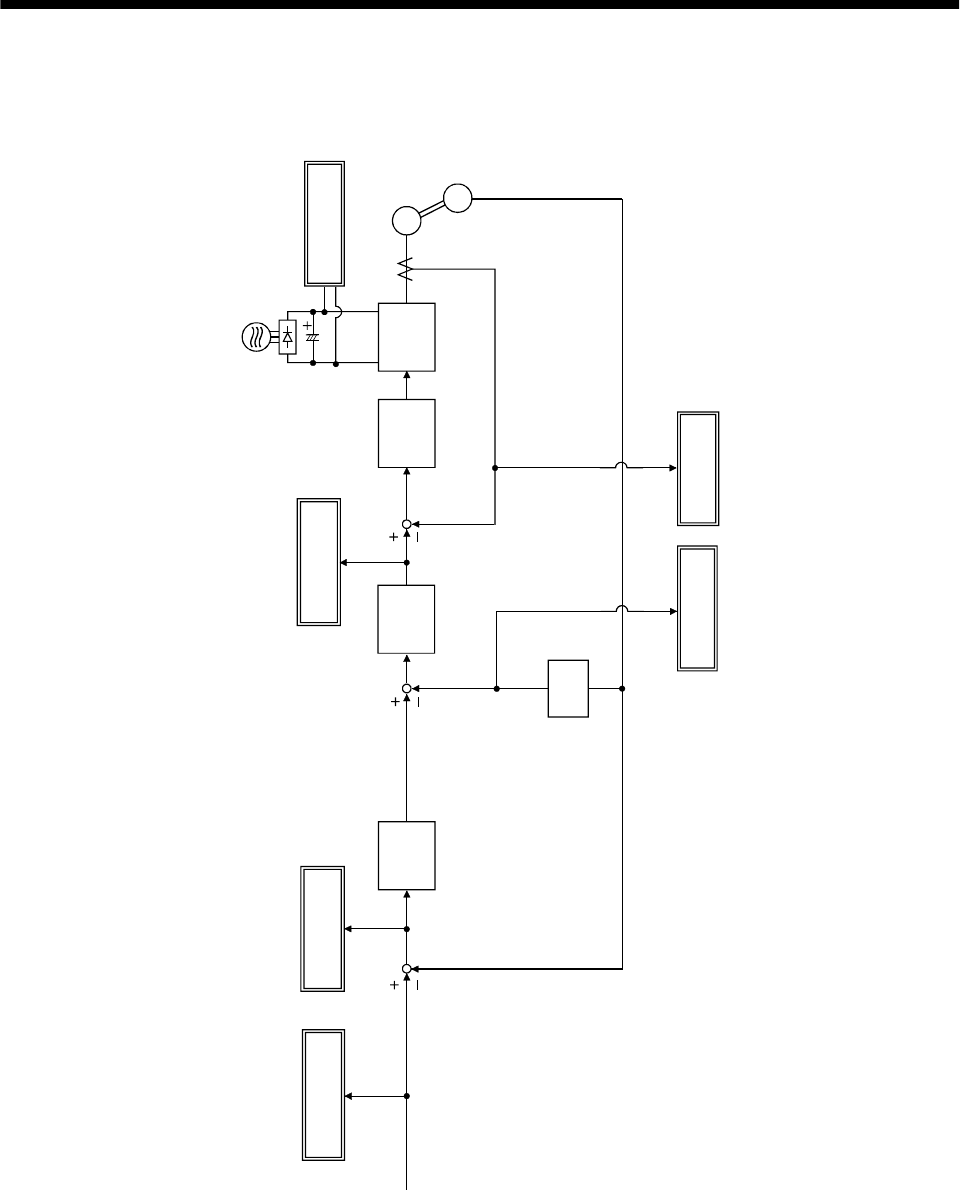
5 - 32
5. PARAMETERS
(3) Analog monitor block diagram
PWM M
Current
control
Speed
control
Current
command
Position
control
Droop pulse
Differ-
ential
Command
pulse frequency Bus voltage
Speed
command
Command
pulse
Current feedback
Position feedback
Servo Motor
speed
Current
encoder Servo Moto
r
Encoder
Torque
5 - 33
5. PARAMETERS
5.2.3 Using forward/reverse rotation stroke end to change the stopping pattern
The stopping pattern is factory-set to make a sudden stop when the forward/reverse rotation stroke end is
made valid. A slow stop can be made by changing the parameter No. 22 value.
Parameter No.22 Setting Stopping method
0
(initial value)
Sudden stop
Position control mode : Motor stops with droop pulses cleared.
Speed control mode : Motor stops at deceleration time constant of zero.
1
Slow stop
Position control mode : The motor is decelerated to a stop in accordance with the
parameter No. 7 value.
Speed control mode : The motor is decelerated to a stop in accordance with the
parameter No. 12 value.
5.2.4 Alarm history clear
The servo amplifier stores one current alarm and five past alarms from when its power is switched on
first. To control alarms which will occur during operation, clear the alarm history using parameter No.16
before starting operation.
Clearing the alarm history automatically returns to " 0 ".
After setting, this parameter is made valid by switch power from OFF to ON.
Alarm history clear
0: Invalid (not cleared)
1: Valid (cleared)
Parameter No.16
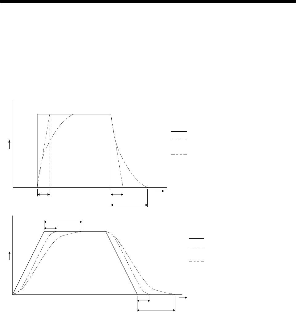
5 - 34
5. PARAMETERS
5.2.5 Position smoothing
By setting the position command acceleration/deceleration time constant (parameter No.7), you can run
the servo motor smoothly in response to a sudden position command.
The following diagrams show the operation patterns of the servo motor in response to a position command
when you have set the position command acceleration/deceleration time constant.
Choose the primary delay or linear acceleration/deceleration in parameter No. 55 according to the
machine used.
(1) For step input
Command
(3t)
tt
Time
t
: Input position command
: Position command after
filtering for primary delay
: Position command after filtering
for linear acceleration/deceleration
: Position command acceleration/
deceleration time constant (parameter No. 7)
(2) For trapezoidal input
Command
Tim
e
t
(3t)
t
(3t)
t
: Input position command
: Position command after
filtering for primary delay
: Position command after filtering
for linear acceleration/deceleration
: Position command acceleration/
deceleration time constant
(parameter No. 7)
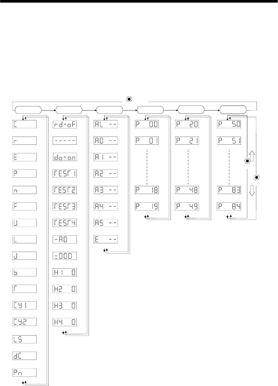
6 - 1
6. DISPLAY AND OPERATION
6. DISPLAY AND OPERATION
6.1 Display flowchart
Use the display (5-digit, 7-segment LED) on the front panel of the servo amplifier for status display,
parameter setting, etc. Set the parameters before operation, diagnose an alarm, confirm external
sequences, and/or confirm the operation status. Press the "MODE" "UP" or "DOWN" button once to move to
the next screen.
To refer to or set the expansion parameters, make them valid with parameter No. 19 (parameter write
disable).
Cumulative feedback
pulses [pulse]
Motor speed
[r/min]
Droop pulses
[pulse]
Cumulative command
pulses [pulse]
Command pulse
frequency [kpps]
Speed command voltage
Speed limit voltage[mV]
Torque limit voltage
Torque command voltage
Regenerative load
ratio [%]
Effective load ratio
[%]
Peak load ratio
[%]
Within one-revolution
position low [pulse]
ABS counter
[rev]
Load inertia moment
ratio [times]
Sequence
External I/O
signal display
Output signal
forced output
Test operation
Jog feed
Test operation
Positioning operation
Test operation
Motor-less operation
Software version L
Software version H
Automatic VC offset
Current alarm
Last alarm
Second alarm in past
Third alarm in past
Fourth alarm in past
Fifth alarm in past
Sixth alarm in past
Parameter error No.
Parameter No. 0
Parameter No. 1
Parameter No. 18
Parameter No. 19
Parameter No. 20
Parameter No. 21
Parameter No. 48
Parameter No. 49
(Note)
Note. The initial status display at power-on depends on the control mode.
Position control mode: Cumulative feedback pulses(C), Speed control mode: Motor speed(r),
Torque control mode: Torque command voltage(U)
Also
,
p
arameter No. 18 can be used to chan
g
e the initial indication of the status dis
p
la
y
at
p
ower-on.
MODE
button
DOWN
UP
Status display Diagnosis Basic
parameters Expansion
parameters 1
Alarm Expansion
parameters 2
Parameter No. 50
Parameter No. 51
Parameter No. 83
Parameter No. 84
Instantaneous torque
[%]
Within one-revolution
position, high [100 pulses]
Bus voltage [V]
Test operation
Machine analyzer operation
Motor series ID
Motor type ID
Encoder ID
[mV]
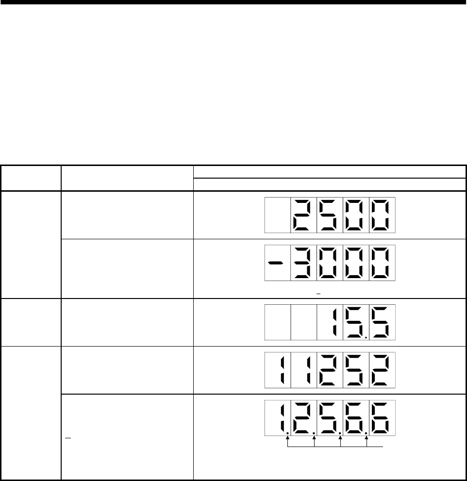
6 - 2
6. DISPLAY AND OPERATION
6.2 Status display
The servo status during operation is shown on the 5-digit, 7-segment LED display. Press the "UP" or
"DOWN" button to change display data as desired. When the required data is selected, the corresponding
symbol appears. Press the "SET" button to display its data. At only power-on, however, data appears after
the symbol of the status display selected in parameter No. 18 has been shown for 2[s].
The servo amplifier display shows the lower five digits of 16 data items such as the servo motor speed.
6.2.1 Display examples
The following table lists display examples:
Displayed data
Item Status Servo amplifier display
Forward rotation at 3000r/min
Servo motor
speed
Reverse rotation at 3000r/min
Reverse rotation is indicated by " ".
Load inertia
moment 15.5 times
11252pulse
Multi-
revolution
counter 12566pulse Lit
Negative value is indicated by the lit decimal points in the upper four
digits.

6 - 3
6. DISPLAY AND OPERATION
6.2.2 Status display list
The following table lists the servo statuses that may be shown:
Refer to Appendix 2 for the measurement point.
Name Symbol Unit Description Display
range
Cumulative feedback
pulses C pulse Feedback pulses from the servo motor encoder are counted and
displayed. The value in excess of 99999 is counted, bus since the
servo amplifier display is five digits, it shows the lower five digits of
the actual value. Press the "SET" button to reset the display value to
zero.
Reverse rotation is indicated by the lit decimal points in the upper
four digits.
99999
to
99999
Servo motor speed r r/min The servo motor speed is displayed.
The value rounded off is displayed in 0.1r/min. 5400
to
5400
Droop pulses E pulse The number of droop pulses in the deviation counter is displayed.
When the servo motor is rotating in the reverse direction, the
decimal points in the upper four digits are lit.
Since the servo amplifier display is five digits, it shows the lower five
digits of the actual value.
The number of pulses displayed is not yet multiplied by the electronic
gear.
99999
to
99999
Cumulative command
pulses P pulse The position command input pulses are counted and displayed.
As the value displayed is not yet multiplied by the electronic gear
(CMX/CDV), it may not match the indication of the cumulative
feedback pulses.
The value in excess of 99999 is counted, but since the servo
amplifier display is five digits, it shows the lower five digits of the
actual value. Press the "SET" button to reset the display value to
zero. When the servo motor is rotating in the reverse direction, the
decimal points in the upper four digits are lit.
99999
to
99999
Command pulse
frequency n kpps The frequency of the position command input pulses is displayed.
The value displayed is not multiplied by the electronic gear
(CMX/CDV).
800
to
800
(1) Torque control mode
Analog speed limit (VLA) voltage is displayed.
Analog speed
command voltage
Analog speed limit
voltage
FV
(2) Speed control mode
Analog speed command (VC) voltage is displayed.
10.00
to
10.00
U V (1) Position control mode, speed control mode
Analog torque limit (TLA) voltage is displayed. 0
to
10V
Analog torque
command voltage
Analog torque limit
voltage (2) Torque control mode
Analog torque command (TLA) voltage is displayed. 10
to
10V
Regenerative load
ratio L % The ratio of regenerative power to permissible regenerative power is
displayed in %. 0
to
100
Effective load ratio J % The continuous effective load torque is displayed.
The effective value in the past 15 seconds is displayed relative to the
rated torque of 100%.
0
to
300
Peak load ratio b % The maximum torque generated during acceleration/deceleration, etc.
The highest value in the past 15 seconds is displayed relative to the
rated torque of 100%.
0
to
400
Instantaneous torque T % Torque that occurred instantaneously is displayed.
The value of the torque that occurred is displayed in real time
relative to the rate torque of 100%.
0
to
400
Within one-revolution
position low Cy1 pulse Position within one revolution is displayed in encoder pulses.
The value returns to 0 when it exceeds the maximum number of
pulses.
The value is incremented in the CCW direction of rotation.
0
to
99999

6 - 4
6. DISPLAY AND OPERATION
Name Symbol Unit Description Display
range
Within one-revolution
position high Cy2 100
pulse The within one-revolution position is displayed in 100 pulse
increments of the encoder.
The value returns to 0 when it exceeds the maximum number of
pulses.
The value is incremented in the CCW direction of rotation.
0
to
1310
ABS counter LS rev Travel value from the home position in the absolute position
detection systems is displayed in terms of the absolute position
detectors counter value.
32768
to
32767
Load inertia moment
ratio dC 0.1
Times The estimated ratio of the load inertia moment to the servo motor
shaft inertia moment is displayed. 0.0
to
300.0
Bus voltage Pn V The voltage (across P-N) of the main circuit converter is displayed. 0
to
450
6.2.3 Changing the status display screen
The status display item of the servo amplifier display shown at power-on can be changed by changing the
parameter No. 18 settings.
The item displayed in the initial status changes with the control mode as follows:
Control mode
Position
Position/speed
Speed
Speed/torque
Torque
Torque/position
Status display at power-on
Cumulative feedback pulses
Cumulative feedback pulses/servo motor speed
Servo motor speed
Servo motor speed/analog torque command voltage
Analog torque command voltage
Analog torque command voltage/cumulative feedback pulses
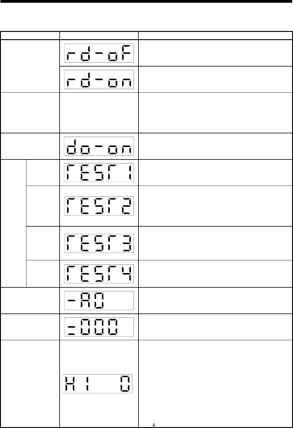
6 - 5
6. DISPLAY AND OPERATION
6.3 Diagnostic mode
Name Display Description
Not ready.
Indicates that the servo amplifier is being initialized or an alarm
has occurred.
Sequence Ready.
Indicates that the servo was switched on after completion of
initialization and the servo amplifier is ready to operate.
External I/O signal
display
Refer to section 6.6. Indicates the ON-OFF states of the external I/O signals.
The upper segments correspond to the input signals and the
lower segments to the output signals.
Lit: ON
Extinguished: OFF
The I/O signals can be changed using parameters No. 43 to 49.
Output signal (DO)
forced output The digital output signal can be forced on/off. For more
information, refer to section 6.7.
Jog feed Jog operation can be performed when there is no command from
the external command device.
For details, refer to section 6.8.2.
Positioning
operation
The MR Configurator (servo configuration software MRZJW3-
SETUP151E) is required for positioning operation. This operation
cannot be performed from the operation section of the servo
amplifier.
Positioning operation can be performed once when there is no
command from the external command device.
Motorless
operation
Without connection of the servo motor, the servo amplifier
provides output signals and displays the status as if the servo
motor is running actually in response to the external input
signal.
For details, refer to section 6.8.4.
Test
operation
mode
Machine
analyzer
operation
Merely connecting the servo amplifier allows the resonance point
of the mechanical system to be measured.
The MR Configurator (servo configuration software MRZJW3-
SETUP151E) is required for machine analyzer operation.
Software version low Indicates the version of the software.
Software version high Indicates the system number of the software.
Automatic VC offset
If offset voltages in the analog circuits inside and outside the
servo amplifier cause the servo motor to rotate slowly at the
analog speed command (VC) or analog speed limit (VLA) of 0V,
this function automatically makes zero-adjustment of offset
voltages.
When using this function, make it valid in the following
procedure. Making it valid causes the parameter No. 29 value to
be the automatically adjusted offset voltage.
1) Press "SET" once.
2) Set the number in the first digit to 1 with "UP"/"DOWN".
3) Press "SET".
You cannot use this function if the input voltage of VC or VLA
is 0.4V or more.

6 - 6
6. DISPLAY AND OPERATION
Name Display Description
Motor series
Press the "SET" button to show the motor series ID of the servo
motor currently connected.
For indication details, refer to the optional MELSERVO Servo
Motor Instruction Manual.
Motor type
Press the "SET" button to show the motor type ID of the servo
motor currently connected.
For indication details, refer to the optional MELSERVO Servo
Motor Instruction Manual.
Encoder
Press the "SET" button to show the encoder ID of the servo motor
currently connected.
For indication details, refer to the optional MELSERVO Servo
Motor Instruction Manual.
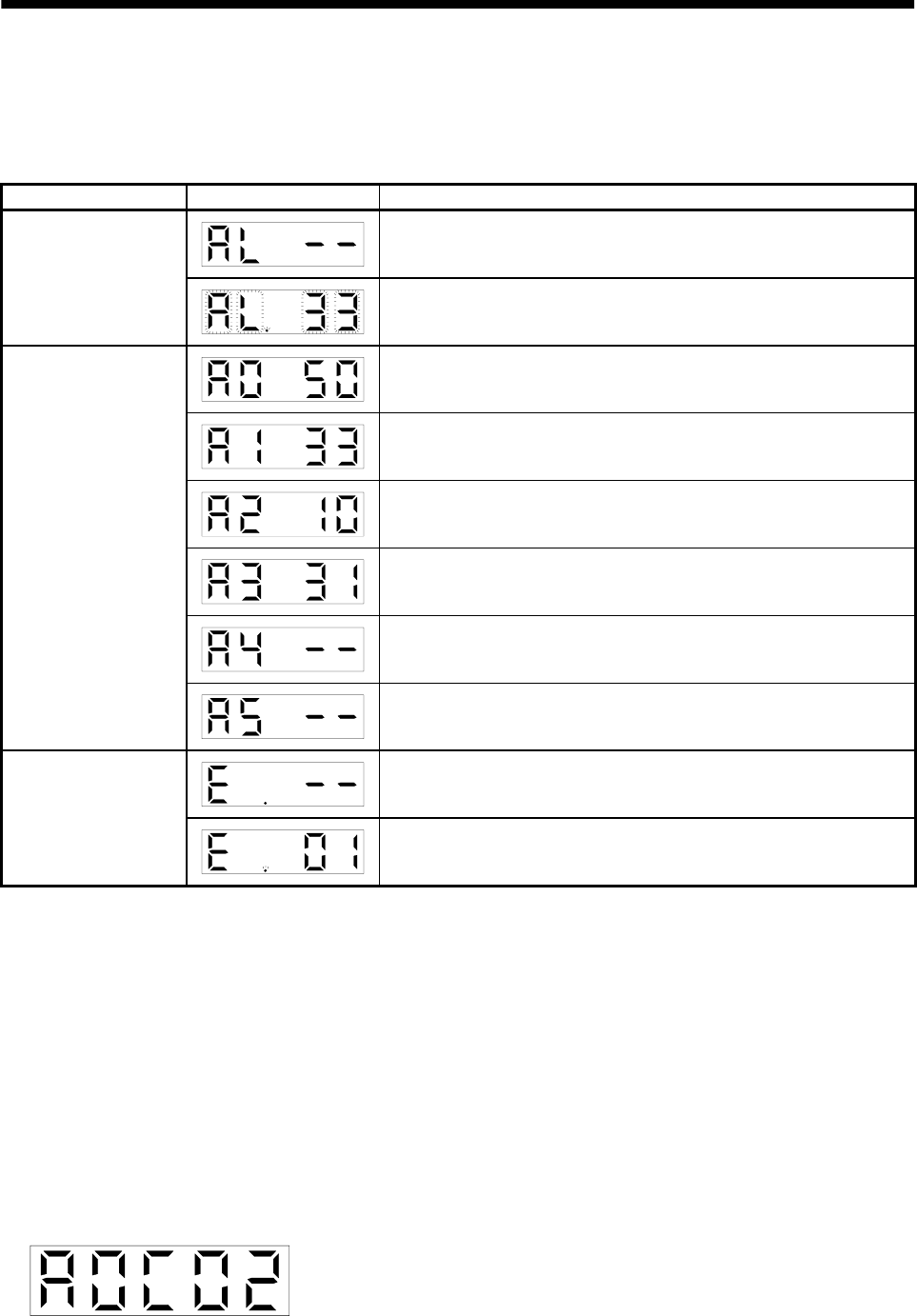
6 - 7
6. DISPLAY AND OPERATION
6.4 Alarm mode
The current alarm, past alarm history and parameter error are displayed. The lower 2 digits on the
display indicate the alarm number that has occurred or the parameter number in error. Display examples
are shown below.
Name Display Description
Indicates no occurrence of an alarm.
Current alarm Indicates the occurrence of overvoltage (AL.33).
Flickers at occurrence of the alarm.
Indicates that the last alarm is overload 1 (AL.50).
Indicates that the second alarm in the past is overvoltage (AL.33).
Indicates that the third alarm in the past is undervoltage (AL.10).
Indicates that the fourth alarm in the past is overspeed (AL.31).
Indicates that there is no fifth alarm in the past.
Alarm history
Indicates that there is no sixth alarm in the past.
Indicates no occurrence of parameter error (AL.37).
Parameter error No.
Indicates that the data of parameter No. 1 is faulty.
Functions at occurrence of an alarm
(1) Any mode screen displays the current alarm.
(2) Even during alarm occurrence, the other screen can be viewed by pressing the button in the operation
area. At this time, the decimal point in the fourth digit remains flickering.
(3) For any alarm, remove its cause and clear it in any of the following methods (for clearable alarms,
refer to Section 10.2.1):
(a) Switch power OFF, then ON.
(b) Press the "SET" button on the current alarm screen.
(c) Turn on the alarm reset (RES).
(4) Use parameter No. 16 to clear the alarm history.
(5) Pressing "SET" on the alarm history display screen for 2s or longer shows the following detailed
information display screen. Note that this is provided for maintenance by the manufacturer.
(6) Press "UP" or "DOWN" to move to the next history.
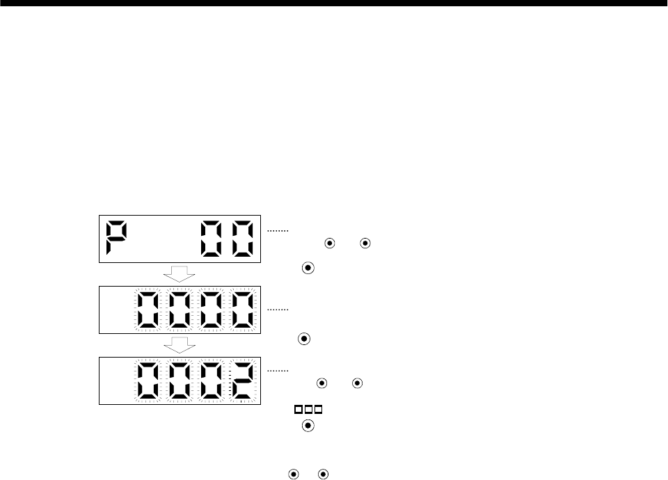
6 - 8
6. DISPLAY AND OPERATION
6.5 Parameter mode
The parameters whose abbreviations are marked* are made valid by changing the setting and then
switching power off once and switching it on again. Refer to Section 5.1.2.
(1) Operation example
The following example shows the operation procedure performed after power-on to change the control
mode (parameter No. 0) to the speed control mode.
Using the "MODE" button, show the basic parameter screen.
The set value of the specified parameter number flickers.
UP DOWN
The parameter number is displayed.
Press or to change the number.
Press SET twice.
Press UP once.
During flickering, the set value can be changed.
Use or .
Press SET to enter.
( 2: Speed control mode)
UP DOWN
To shift to the next parameter, press the UP DOWN
/ button.
When changing the parameter No. 0 setting, change its set value, then switch power off once and
switch it on again to make the new value valid.
(2) Expansion parameters
To use the expansion parameters, change the setting of parameter No. 19 (parameter write disable).
Refer to section 5.1.1.
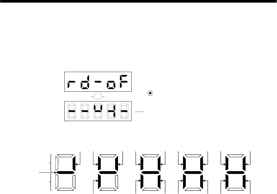
6 - 9
6. DISPLAY AND OPERATION
6.6 External I/O signal display
The ON/OFF states of the digital I/O signals connected to the servo amplifier can be confirmed.
(1) Operation
Call the display screen shown after power-on.
Using the "MODE" button, show the diagnostic screen.
Press UP once.
External I/O signal display screen
(2) Display definition
CN1B
7
CN1B
9CN1B
8
CN1A
14
CN1A
8
CN1B
4
CN1B
18
CN1B
14 CN1B
5CN1B
17 CN1B
16
CN1B
19
CN1B
6CN1A
19
CN1A
18
Lit: ON
Extinguished: OFF
Input signals
Output signals
CN1B
15
A
lways lit
The 7-segment LED shown above indicates ON/OFF.
Each segment at top indicates the input signal and each segment at bottom indicates the output signal.
The signals corresponding to the pins in the respective control modes are indicated below:
6 - 10
6. DISPLAY AND OPERATION
(a) Control modes and I/O signals
(Note 2) Symbols of I/O signals in control modes
Connector Pin No.
Signal
input/output
(Note 1) I/O P P/S S S/T T T/P
Related
parameter
8 I CR CR/SP1 SP1 SP1 SP1 SP1/CR No.43 to 48
14O OPOPOPOPOPOP
18 O INP INP/SA SA SA/ /INP No.49
CN1A
19O RDRDRDRDRDRDNo.49
(Note 3) 4 O DO1 DO1 DO1 DO1 DO1 DO1
5 I SON SON SON SON SON SON No.43 to 48
6 O TLC TLC TLC TLC/VLC VLC VLC/TLC No.49
7 I LOP SP2 LOP SP2 LOP No.43 to 48
8 I PC PC/ST1 ST1 ST1/RS2 RS2 RS2/PC No.43 to 48
9 I TL TL/ST2 ST2 ST2/RS1 RS1 RS1/TL No.43 to 48
14 I RES RES RES RES RES RES No.43 to 48
15 I EMG EMG EMG EMG EMG EMG
16 I LSP LSP LSP LSP/ /LSP
17 I LSN LSN LSN LSN/ /LSN
18 O ALM ALM ALM ALM ALM ALM No.49
CN1B
19 O ZSP ZSP ZSP ZSP ZSP ZSP No.1 49
Note 1. I: Input signal, O: Output signal
2. P: Position control mode, S: Speed control mode, T: Torque control mode, P/S: Position/speed control change mode, S/T:
Speed/torque control change mode, T/P: Torque/position control change mode
3. CN1B-4 and CN1A-18 output signals are the same.
(b) Symbol and signal names
Symbol Signal name Symbol Signal name
SON Servo-on EMG Emergency stop
LSP Forward rotation stroke end LOP Control change
LSN Reverse rotation stroke end TLC Limiting torque
CR Clear VLC Limiting speed
SP1 Speed selection 1 RD Ready
SP2 Speed selection 2 ZSP Zero speed
PC Proportion control INP In position
ST1 Forward rotation start SA Speed reached
ST2 Reverse rotation start ALM Trouble
RS1 Forward rotation selection WNG Warning
RS2 Reverse rotation selection OP Encoder Z-phase pulse (open collector)
TL Torque limit BWNG Battery warning
RES Reset
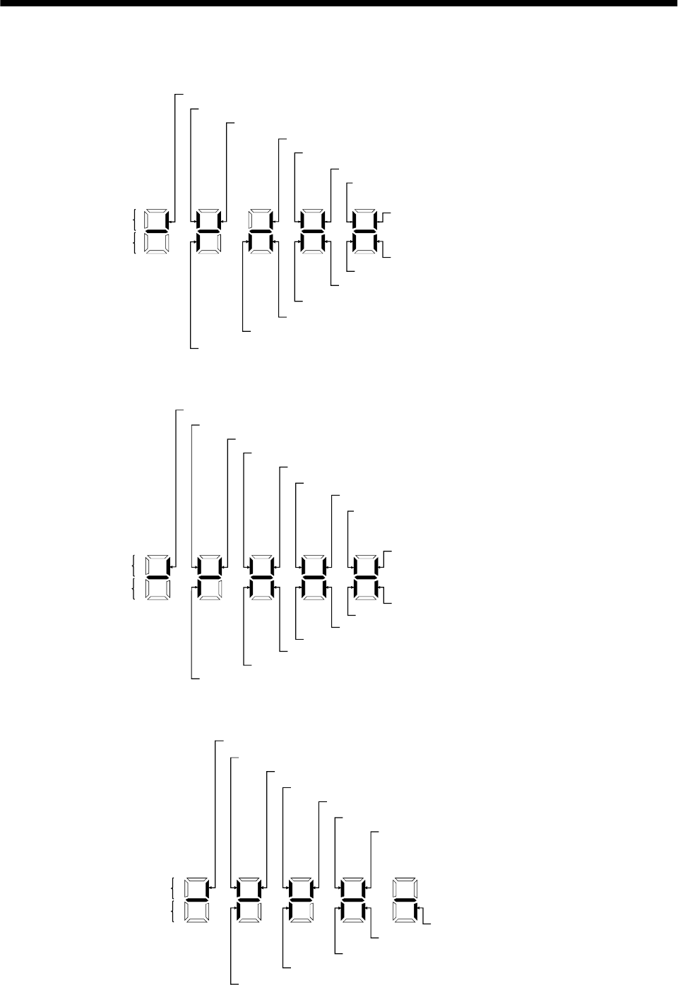
6 - 11
6. DISPLAY AND OPERATION
(3) Default signal indications
(a) Position control mode
Lit: ON
Extinguished:OFF
Input signals
Output signals
TL (CN 1 B-9) Torque limit
PC (CN 1 B-8) Proportional control
CR (CN 1 A-8) Clear
RES (CN 1 B-14) Reset
SON(CN 1 B-5) Servo-on
LSN (CN 1 B-17) Reverse rotation stroke end
LSP (CN 1 B-16) Forward rotation stroke end
RD (CN 1 A-19) Ready
INP (CN 1 A-18) In position
ZSP (CN 1 B-19) Zero speed
TLC (CN 1 B-6) Limiting torque
DO1 (CN 1 B-4) In position
ALM (CN 1 B-18) Trouble
OP (CN 1 A-14) Encoder Z-phase pulse
EMG(CN 1 B-15) Emergency stop
(b) Speed control mode
SP1 (CN 1 A-8) Speed selection 1
RES (CN 1 B-14) Reset
SON (CN 1 B-5) Servo-on
LSN (CN 1 B-17) External emergency stop
LSP (CN 1 B-16) Forward rotation stroke end
Lit: ON
Extinguished: OFF
RD (CN 1 A-19) Ready
SA (CN 1 A-18) Limiting speed
ZSP (CN 1 B-19) Zero speed
TLC (CN 1 B-6) Limiting torque
DO1 (CN 1 B-4) Limiting speed
ALM (CN 1 B-18) Trouble
OP (CN 1 A-14) Encoder Z-phase pulse
Input signals
Output signals
SP2 (CN 1 B-7) Speed selection 2
ST1 (CN 1 B-8) For ward rotation start
ST2 (CN 1 B-9) Reverse rotation start
EMG(CN 1 B-15) Emergency stop
(c) Torque control mode
RS1 (CN 1 B-9) Forward rotation selection
RS2 (CN 1 B-8) Reverse rotation selection
SP2 (CN 1 B-7) Speed selection 2
SP1 (CN 1 A-8) Speed selection 1
RES (CN 1 B-14) Reset
SON (CN 1 B-5) Servo-on
Lit: ON
Extinguished: OFF
RD (CN 1 A-19) Ready
ZSP (CN 1 B-19) Zero speed
VLC (CN 1 B-6) Speed reached
ALM (CN 1 B-18) Trouble
Input signals
Output signals
OP (CN 1 A-14) Encoder Z-phase pulse
EMG(CN 1 B-15) Emergency stop
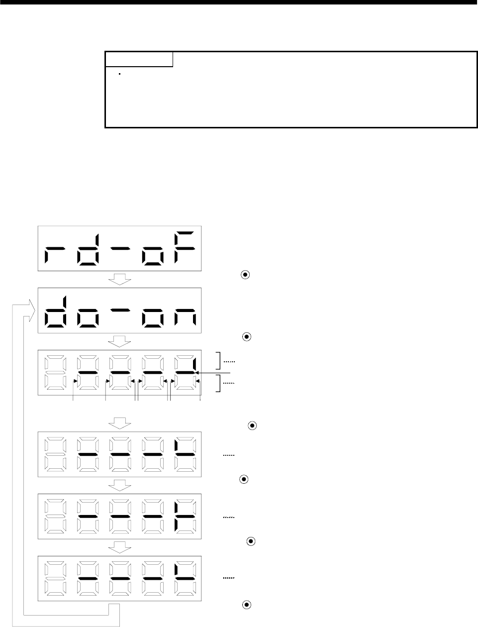
6 - 12
6. DISPLAY AND OPERATION
6.7 Output signal (DO) forced output
POINT
When the servo system is used in a vertical lift application, turning on the
electromagnetic brake interlock (MBR) after assigning it to pin CN1B-19
will release the electromagnetic brake, causing a drop. Take drop
preventive measures on the machine side.
The output signal can be forced on/off independently of the servo status. This function is used for output
signal wiring check, etc. This operation must be performed in the servo off state servo-on (SON).
Operation
Call the display screen shown after power-on.
Using the "MODE" button, show the diagnostic screen.
Press UP twice.
Press SET for more than 2 seconds.
Switch on/off the signal below the lit segment.
Indicates the ON/OFF of the output signal. The correspondences
between segments and signals are as in the output signals of the
external I/O signal display.
(Lit: ON, extinguished: OFF)
Press MODE once.
The segment above CN1A-pin 18 is lit.
Press UP once.
CN1A-pin 18 is switched on.
(CN1A-pin 18-SG conduct.)
Press DOWN once.
CN1A-pin 18 is switched off.
Press SET for more than 2 seconds.
CN1A
14 CN1B
18 CN1B
4CN1B
6CN1B
19 CN1A
18 CN1A
19
Always lit
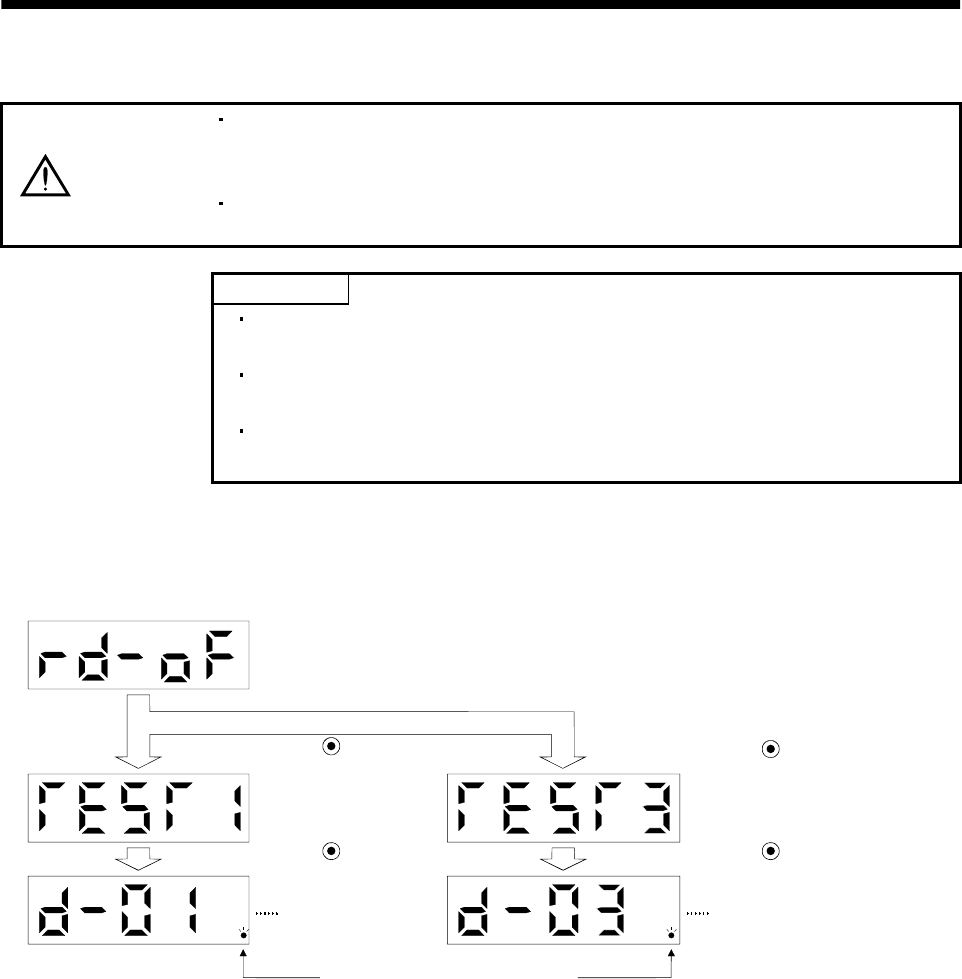
6 - 13
6. DISPLAY AND OPERATION
6.8 Test operation mode
CAUTION
The test operation mode is designed to confirm servo operation and not to confirm
machine operation. In this mode, do not use the servo motor with the machine.
Always use the servo motor alone.
If any operational fault has occurred, stop operation using the emergency stop
(EMG) signal.
POINT
The test operation mode cannot be used in the absolute position detection
system. Use it after choosing "Incremental system" in parameter No. 1.
The MR Configurator (servo configuration software) is required to perform
positioning operation.
Test operation cannot be performed if the servo-on (SON) is not turned
OFF.
6.8.1 Mode change
Call the display screen shown after power-on. Choose jog operation/motor-less operation in the following
procedure. Using the "MODE" button, show the diagnostic screen.
When this screen
appears, jog feed can
be performed.
Press UP three times.
Press SET for more
than 2s.
Flickers in the test operation mode.
Press UP five times.
Press SET for more than 2s.
When this screen is displayed,
motor-less operation can be
performed.
6 - 14
6. DISPLAY AND OPERATION
6.8.2 Jog operation
Jog operation can be performed when there is no command from the external command device.
(1) Operation
Connect EMG-SG to start jog operation and connect VDD-COM to use the internal power supply.
Hold down the "UP" or "DOWN" button to run the servo motor. Release it to stop. When using the MR
Configurator (servo configuration software), you can change the operation conditions. The initial
conditions and setting ranges for operation are listed below:
Item Initial setting Setting range
Speed [r/min] 200 0 to instantaneous permissible speed
Acceleration/deceleration time constant [ms] 1000 0 to 50000
How to use the buttons is explained below:
Button Description
"UP" Press to start CCW rotation.
Release to stop.
"DOWN" Press to start CW rotation.
Release to stop.
If the communication cable is disconnected during jog operation performed by using the MR
Configurator (servo configuration software), the servo motor will be decelerated to a stop.
(2) Status display
You can confirm the servo status during jog operation.
Pressing the "MODE" button in the jog operation-ready status calls the status display screen. With this
screen being shown, perform jog operation with the "UP" or "DOWN" button. Every time you press the
"MODE" button, the next status display screen appears, and on completion of a screen cycle, pressing
that button returns to the jog operation-ready status screen. For full information of the status display,
refer to Section 6.2. In the test operation mode, you cannot use the "UP" and "DOWN" buttons to
change the status display screen from one to another.
(3) Termination of jog operation
To end the jog operation, switch power off once or press the "MODE" button to switch to the next
screen and then hold down the "SET" button for 2 or more seconds.
6 - 15
6. DISPLAY AND OPERATION
6.8.3 Positioning operation
POINT
The MR Configurator (servo configuration software) is required to perform
positioning operation.
Positioning operation can be performed once when there is no command from the external command
device.
(1) Operation
Connect EMG-SG to start positioning operation and connect VDD-COM to use the internal power
supply.
Pressing the "Forward" or "Reverse" click on the MR Configurator (servo configuration software) starts
the servo motor, which will then stop after moving the preset travel distance. You can change the
operation conditions on the MR Configurator (servo configuration software). The initial conditions and
setting ranges for operation are listed below:
Item Initial setting Setting range
Travel distance [pulse] 10000 0 to 9999999
Speed [r/min] 200 0 to instantaneous permissible speed
Acceleration/deceleration time constant [ms] 1000 0 to 50000
How to use the buttons is explained below:
Button Description
"Forward" Click to start positioning operation CCW.
"Reverse" Click to start positioning operation CW.
"Pause"
Click during operation to make a temporary stop. Click the
"Pause" button again erases the remaining distance.
To resume operation, press the click that was pressed to start
the operation.
If the communication cable is disconnected during positioning operation, the servo motor will come
to a sudden stop.
(2) Status display
You can monitor the status display even during positioning operation.

6 - 16
6. DISPLAY AND OPERATION
6.8.4 Motor-less operation
Without connecting the servo motor, you can provide output signals or monitor the status display as if the
servo motor is running in response to external input signals. This operation can be used to check the
sequence of a host programmable controller or the like.
(1) Operation
After turning off the signal across SON-SG, choose motor-less operation. After that, perform external
operation as in ordinary operation.
(2) Status display
You can confirm the servo status during motor-less operation.
Pressing the "MODE" button in the motor-less operation-ready status calls the status display screen.
With this screen being shown, perform motor-less operation. Every time you press the "MODE" button,
the next status display screen appears, and on completion of a screen cycle, pressing that button
returns to the motor-less operation-ready status screen. For full information of the status display,
refer to Section 6.2. In the test operation mode, you cannot use the "UP" and "DOWN" buttons to
change the status display screen from one to another.
(3) Termination of motor-less operation
To terminate the motor-less operation, switch power off.
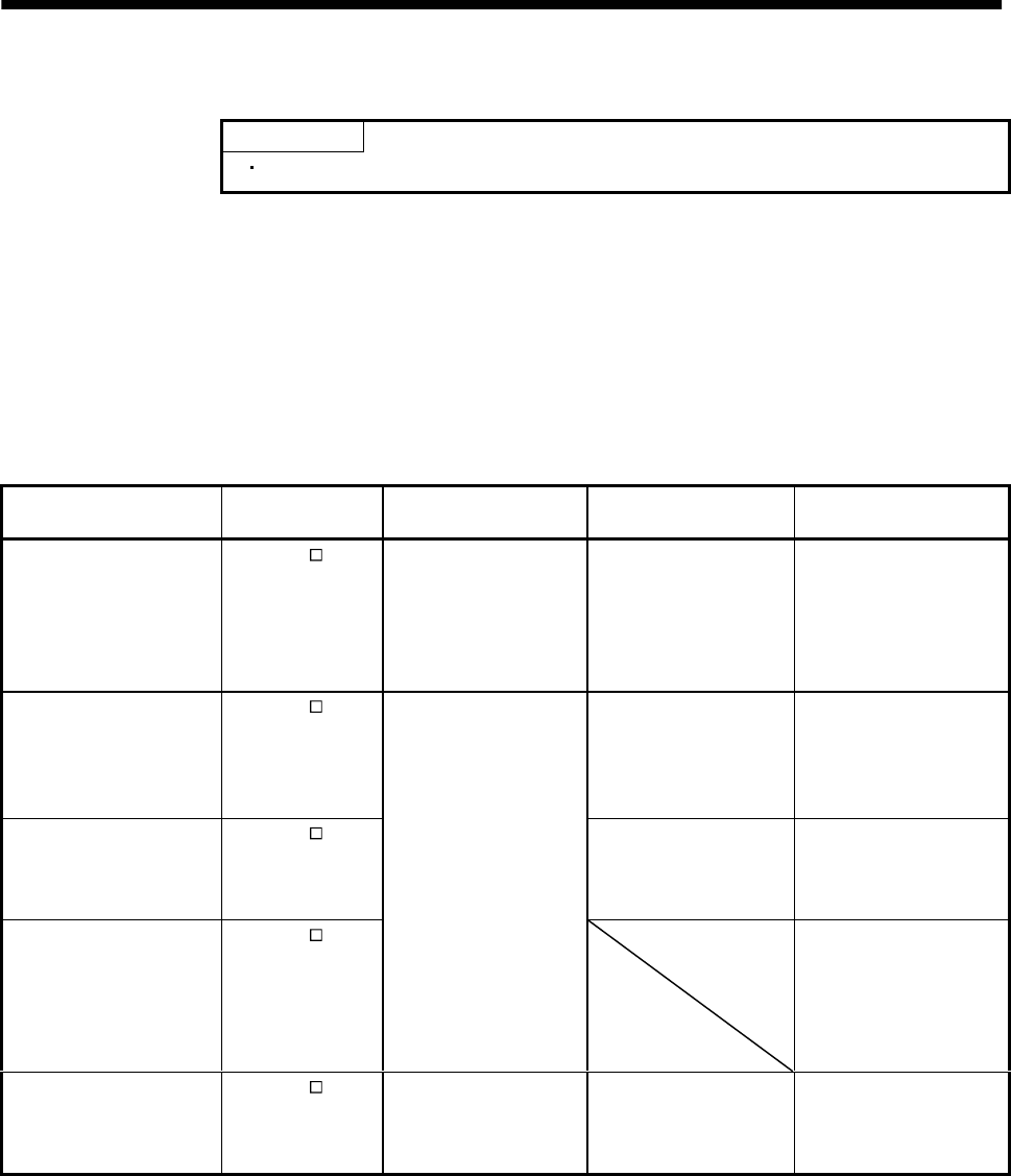
7 - 1
7. GENERAL GAIN ADJUSTMENT
7. GENERAL GAIN ADJUSTMENT
POINT
For use in the torque control mode, you need not make gain adjustment.
7.1 Different adjustment methods
7.1.1 Adjustment on a single servo amplifier
The gain adjustment in this section can be made on a single servo amplifier. For gain adjustment, first
execute auto tuning mode 1. If you are not satisfied with the results, execute auto tuning mode 2, manual
mode 1 and manual mode 2 in this order.
(1) Gain adjustment mode explanation
Gain adjustment mode Parameter No. 2
setting
Estimation of load inertia
moment ratio
Automatically set
parameters Manually set parameters
Auto tuning mode 1
(initial value) 010 Always estimated PG1 (parameter No. 6)
GD2 (parameter No. 34)
PG2 (parameter No. 35)
VG1 (parameter No. 36)
VG2 (parameter No. 37)
VIC (parameter No. 38)
Response level setting of
parameter No. 2
Auto tuning mode 2 020 PG1 (parameter No. 6)
PG2 (parameter No. 35)
VG1 (parameter No. 36)
VG2 (parameter No. 37)
VIC (parameter No. 38)
GD2 (parameter No. 34)
Response level setting of
parameter No. 2
Manual mode 1 030 PG2 (parameter No. 35)
VG1 (parameter No. 36) PG1 (parameter No. 6)
GD2 (parameter No. 34)
VG2 (parameter No. 37)
VIC (parameter No. 38)
Manual mode 2 040
Fixed to parameter No.
34 value
PG1 (parameter No. 6)
GD2 (parameter No. 34)
PG2 (parameter No. 35)
VG1 (parameter No. 36)
VG2 (parameter No. 37)
VIC (parameter No. 38)
Interpolation mode 000 Always estimated GD2 (parameter No. 34)
PG2 (parameter No. 35)
VG2 (parameter No. 37)
VIC (parameter No. 38)
PG1 (parameter No. 6)
VG1 (parameter No. 36)
7 - 2
7. GENERAL GAIN ADJUSTMENT
(2) Adjustment sequence and mode usage
Usage
Used when you want to
match the position gain
(PG1) between 2 or more
axes. Normally not used for
other purposes.
Allows adjustment by
merely changing the
response level setting.
First use this mode to make
adjustment.
Used when the conditions of
auto tuning mode 1 are not
met and the load inertia
moment ratio could not be
estimated properly, for
example.
This mode permits
adjustment easily with three
gains if you were not
satisfied with auto tuning
results.
END
Interpolation
made for 2 or more
axes?
START
Operation
Auto tuning mode 2
OK?
Manual mode 1
OK?
Manual mode 2
OK?
OK?
No
No
Yes
No
Yes
No
Yes
No
Yes
Auto tuning mode 1
Operation
Interpolation mode
Operation
Operation
Yes
You can adjust all gains
manually when you want to
do fast settling or the like.
7.1.2 Adjustment using MR Configurator (servo configuration software)
This section gives the functions and adjustment that may be performed by using the servo amplifier with
the MR Configurator (servo configuration software) which operates on a personal computer.
Function Description Adjustment
Machine analyzer With the machine and servo motor
coupled, the characteristic of the
mechanical system can be measured by
giving a random vibration command from
the personal computer to the servo and
measuring the machine response.
You can grasp the machine resonance frequency and
determine the notch frequency of the machine
resonance suppression filter.
You can automatically set the optimum gains in
response to the machine characteristic. This simple
adjustment is suitable for a machine which has large
machine resonance and does not require much settling
time.
Gain search Executing gain search under to-and-fro
positioning command measures settling
characteristic while simultaneously
changing gains, and automatically
searches for gains which make settling
time shortest.
You can automatically set gains which make positioning
settling time shortest.
Machine simulation Response at positioning settling of a
machine can be simulated from machine
analyzer results on personal computer.
You can optimize gain adjustment and command
pattern on personal computer.
7 - 3
7. GENERAL GAIN ADJUSTMENT
7.2 Auto tuning
7.2.1 Auto tuning mode
The servo amplifier has a real-time auto tuning function which estimates the machine characteristic (load
inertia moment ratio) in real time and automatically sets the optimum gains according to that value. This
function permits ease of gain adjustment of the servo amplifier.
(1) Auto tuning mode 1
The servo amplifier is factory-set to the auto tuning mode 1.
In this mode, the load inertia moment ratio of a machine is always estimated to set the optimum gains
automatically.
The following parameters are automatically adjusted in the auto tuning mode 1.
Parameter No. Abbreviation Name
6PG1Position control gain 1
34 GD2 Ratio of load inertia moment to servo motor inertia moment
35 PG2 Position control gain 2
36 VG1 Speed control gain 1
37 VG2 Speed control gain 2
38 VIC Speed integral compensation
POINT
The auto tuning mode 1 may not be performed properly if the following
conditions are not satisfied.
Time to reach 2000r/min is the acceleration/deceleration time constant of 5s or
less.
Speed is 150r/min or higher.
The ratio of load inertia moment to servo motor inertia moment is 100
times or less.
The acceleration/deceleration torque is 10% or more of the rated torque.
Under operating conditions which will impose sudden disturbance torque
during acceleration/deceleration or on a machine which is extremely loose,
auto tuning may not function properly, either. In such cases, use the auto
tuning mode 2 or manual mode 1,2 to make gain adjustment.
(2) Auto tuning mode 2
Use the auto tuning mode 2 when proper gain adjustment cannot be made by auto tuning mode 1.
Since the load inertia moment ratio is not estimated in this mode, set the value of a correct load
inertia moment ratio (parameter No. 34).
The following parameters are automatically adjusted in the auto tuning mode 2.
Parameter No. Abbreviation Name
6PG1Position control gain 1
35 PG2 Position control gain 2
36 VG1 Speed control gain 1
37 VG2 Speed control gain 2
38 VIC Speed integral compensation
7 - 4
7. GENERAL GAIN ADJUSTMENT
7.2.2 Auto tuning mode operation
The block diagram of real-time auto tuning is shown below.
Servo
motor
Command
Automatic setting
Control gains
PG1,VG1
PG2,VG2,VIC
Current
control
Current feedback
Load inertia
moment
Encoder
Position/speed
feedback
Real-time auto
tuning section
Speed feedback
Load inertia
moment ratio
estimation section
Gain
table
Parameter No. 2
Gain adjustment
mode selection
First digit
Response level
setting
Parameter No. 34
Load inertia moment
ratio estimation value
Set 0 or 1 to turn on.
Switch
When a servo motor is accelerated/decelerated, the load inertia moment ratio estimation section always
estimates the load inertia moment ratio from the current and speed of the servo motor. The results of
estimation are written to parameter No. 34 (the ratio of load inertia moment to servo motor). These
results can be confirmed on the status display screen of the MR Configurator (servo configuration
software) section.
If the value of the load inertia moment ratio is already known or if estimation cannot be made properly,
chose the "auto tuning mode 2" (parameter No.2: 2 ) to stop the estimation of the load inertia
moment ratio (Switch in above diagram turned off), and set the load inertia moment ratio (parameter No.
34) manually.
From the preset load inertia moment ratio (parameter No. 34) value and response level (The first digit of
parameter No. 2), the optimum control gains are automatically set on the basis of the internal gain tale.
The auto tuning results are saved in the EEP-ROM of the servo amplifier every 60 minutes since power-
on. At power-on, auto tuning is performed with the value of each control gain saved in the EEP-ROM
being used as an initial value.
POINT
If sudden disturbance torque is imposed during operation, the estimation
of the inertia moment ratio may malfunction temporarily. In such a case,
choose the "auto tuning mode 2" (parameter No. 2: 020 ) and set the
correct load inertia moment ratio in parameter No. 34.
When any of the auto tuning mode 1, auto tuning mode 2 and manual
mode 1 settings is changed to the manual mode 2 setting, the current
control gains and load inertia moment ratio estimation value are saved in
the EEP-ROM.
7 - 5
7. GENERAL GAIN ADJUSTMENT
7.2.3 Adjustment procedure by auto tuning
Since auto tuning is made valid before shipment from the factory, simply running the servo motor
automatically sets the optimum gains that match the machine. Merely changing the response level
setting value as required completes the adjustment. The adjustment procedure is as follows.
END
Yes
No
Yes
No
No
Yes
Auto tuning adjustment
Acceleration/deceleration repeated
Load inertia moment ratio
estimation value stable?
Auto tuning
conditions not satisfied.
(Estimation of load inertia
moment ratio is difficult)
Adjust response level setting
so that desired response is
achieved on vibration-free level.
Acceleration/deceleration repeated
Requested
performance satisfied?
To manual mode
Choose the auto tuning mode 2
(parameter No.2 : 020 ) and set
the load inertia moment ratio
(parameter No.34) manually.
7 - 6
7. GENERAL GAIN ADJUSTMENT
7.2.4 Response level setting in auto tuning mode
Set the response (The first digit of parameter No.2) of the whole servo system. As the response level
setting is increased, the trackability and settling time for a command decreases, but a too high response
level will generate vibration. Hence, make setting until desired response is obtained within the vibration-
free range.
If the response level setting cannot be increased up to the desired response because of machine resonance
beyond 100Hz, adaptive vibration suppression control (parameter No. 60) or machine resonance
suppression filter (parameter No. 58 59) may be used to suppress machine resonance. Suppressing
machine resonance may allow the response level setting to increase. Refer to Section 8.1 for adaptive
vibration suppression control and machine resonance suppression filter.
Parameter No. 2
Response level setting
Gain adjustment mode selection
Machine characteristic
Response level setting Machine rigidity Machine resonance
frequency guideline Guideline of corresponding machine
1 Low 15Hz
2 20Hz
3 25Hz
430Hz
5 35Hz
6 45Hz
7 55Hz
8 Middle 70Hz
9 85Hz
A 105Hz
B 130Hz
C160Hz
D 200Hz
E 240Hz
F High 300Hz
Large conveyor
Arm robot
General machine
tool conveyor
Precision
working
machine
Inserter
Mounter
Bonder
7 - 7
7. GENERAL GAIN ADJUSTMENT
7.3 Manual mode 1 (simple manual adjustment)
If you are not satisfied with the adjustment of auto tuning, you can make simple manual adjustment with
three parameters.
7.3.1 Operation of manual mode 1
In this mode, setting the three gains of position control gain 1 (PG1), speed control gain 2 (VG2) and
speed integral compensation (VIC) automatically sets the other gains to the optimum values according to
these gains.
PG1
VG2
VIC
PG2
VG1
GD2
Automatic setting
User setting
Therefore, you can adjust the model adaptive control system in the same image as the general PI control
system (position gain, speed gain, speed integral time constant). Here, the position gain corresponds to
PG1, the speed gain to VG2 and the speed integral time constant to VIC. When making gain adjustment
in this mode, set the load inertia moment ratio (parameter No. 34) correctly.
7.3.2 Adjustment by manual mode 1
POINT
If machine resonance occurs, adaptive vibration suppression control
(parameter No. 60) or machine resonance suppression filter (parameter No.
58 59) may be used to suppress machine resonance. (Refer to Section 8.1.)
(1) For speed control
(a) Parameters
The following parameters are used for gain adjustment:
Parameter No. Abbreviation Name
34 GD2 Ratio of load inertia moment to servo motor inertia moment
37 VG2 Speed control gain 2
38 VIC Speed integral compensation
(b) Adjustment procedure
Step Operation Description
1Set an estimated value to the ratio of load inertia moment to servo
motor inertia moment (parameter No. 34).
2Increase the speed control gain 2 (parameter No. 37) within the
vibration- and unusual noise-free range, and return slightly if vibration
takes place.
Increase the speed control gain.
3Decrease the speed integral compensation (parameter No. 38) within
the vibration-free range, and return slightly if vibration takes place. Decrease the time constant of the speed
integral compensation.
4
If the gains cannot be increased due to mechanical system resonance or
the like and the desired response cannot be achieved, response may be
increased by suppressing resonance with adaptive vibration
suppression control or machine resonance suppression filter and then
executing steps 2 and 3.
Suppression of machine resonance.
Refer to Section 8.2, 8.3.
5While checking the settling characteristic and rotational status, fine-
adjust each gain. Fine adjustment
7 - 8
7. GENERAL GAIN ADJUSTMENT
(c)Adjustment description
1) Speed control gain 2 (parameter No. 37)
This parameter determines the response level of the speed control loop. Increasing this value
enhances response but a too high value will make the mechanical system liable to vibrate. The
actual response frequency of the speed loop is as indicated in the following expression:
Speed loop response
frequency(Hz) Speed control gain 2 setting
(1 ratio of load inertia moment to servo motor inertia moment) 2
2) Speed integral compensation (VIC: parameter No. 38)
To eliminate stationary deviation against a command, the speed control loop is under
proportional integral control. For the speed integral compensation, set the time constant of this
integral control. Increasing the setting lowers the response level. However, if the load inertia
moment ratio is large or the mechanical system has any vibratory element, the mechanical
system is liable to vibrate unless the setting is increased to some degree. The guideline is as
indicated in the following expression:
Speed integral compensation
setting(ms) 2000 to 3000
(1 ratio of load inertia moment to
servo motor inertia moment setting 0.1)
Speed control gain 2 setting/
(2) For position control
(a) Parameters
The following parameters are used for gain adjustment:
Parameter No. Abbreviation Name
6PG1Position control gain 1
34 GD2 Ratio of load inertia moment to servo motor inertia moment
37 VG2 Speed control gain 2
38 VIC Speed integral compensation
(b) Adjustment procedure
Step Operation Description
1Set an estimated value to the ratio of load inertia moment to servo
motor inertia moment (parameter No. 34).
2Set a slightly smaller value to the position control gain 1 (parameter
No. 6).
3Increase the speed control gain 2 (parameter No. 37) within the
vibration- and unusual noise-free range, and return slightly if vibration
takes place.
Increase the speed control gain.
4Decrease the speed integral compensation (parameter No. 38) within
the vibration-free range, and return slightly if vibration takes place. Decrease the time constant of the speed
integral compensation.
5 Increase the position control gain 1 (parameter No. 6). Increase the position control gain.
6
If the gains cannot be increased due to mechanical system resonance or
the like and the desired response cannot be achieved, response may be
increased by suppressing resonance with adaptive vibration
suppression control or machine resonance suppression filter and then
executing steps 3 to 5.
Suppression of machine resonance.
Refer to Section 8.1.
7While checking the settling characteristic and rotational status, fine-
adjust each gain. Fine adjustment

7 - 9
7. GENERAL GAIN ADJUSTMENT
(c) Adjustment description
1) Position control gain 1 (parameter No. 6)
This parameter determines the response level of the position control loop. Increasing position
control gain 1 improves trackability to a position command but a too high value will make
overshooting liable to occur at the time of settling.
Position control
gain 1 guideline Speed control gain 2 setting
(1 ratio of load inertia moment to servo motor inertia moment) ( to 1
5
1
3)
2) Speed control gain 2 (VG2: parameter No. 37)
This parameter determines the response level of the speed control loop. Increasing this value
enhances response but a too high value will make the mechanical system liable to vibrate. The
actual response frequency of the speed loop is as indicated in the following expression:
Speed loop response
frequency(Hz) Speed control gain 2 setting
(1 ratio of load inertia moment to servo motor inertia moment) 2
2
3) Speed integral compensation (parameter No. 38)
To eliminate stationary deviation against a command, the speed control loop is under
proportional integral control. For the speed integral compensation, set the time constant of this
integral control. Increasing the setting lowers the response level. However, if the load inertia
moment ratio is large or the mechanical system has any vibratory element, the mechanical
system is liable to vibrate unless the setting is increased to some degree. The guideline is as
indicated in the following expression:
Speed integral
compensation setting(ms) 2000 to 3000
Speed control gain 2 setting/ (1 ratio of load inertia moment to
servo motor inertia moment 2 setting 0.1)

7 - 10
7. GENERAL GAIN ADJUSTMENT
7.4 Interpolation mode
The interpolation mode is used to match the position control gains of the axes when performing the
interpolation operation of servo motors of two or more axes for an X-Y table or the like. In this mode, the
position control gain 2 and speed control gain 2 which determine command trackability are set manually
and the other parameter for gain adjustment are set automatically.
(1) Parameter
(a) Automatically adjusted parameters
The following parameters are automatically adjusted by auto tuning.
Parameter No. Abbreviation Name
34 GD2 Ratio of load inertia moment to servo motor inertia moment
35 PG2 Position control gain 2
37 VG2 Speed control gain 2
38 VIC Speed integral compensation
(b) Manually adjusted parameters
The following parameters are adjustable manually.
Parameter No. Abbreviation Name
6PG1Position control gain 1
36 VG1 Speed control gain 1
(2) Adjustment procedure
Step Operation Description
1Set 15Hz (parameter No. 2: 010 ) as the machine resonance frequency of response
in the auto tuning mode 1. Select the auto tuning mode 1.
2During operation, increase the response level setting (parameter No. 2), and
return the setting if vibration occurs. Adjustment in auto tuning mode
1.
3Check the values of position control gain 1 (parameter No. 6) and speed control
gain 1 (parameter No. 36). Check the upper setting limits.
4 Set the interpolation mode (parameter No. 2: 000 ). Select the interpolation mode.
5Using the position control gain 1 value checked in step 3 as the guideline of the
upper limit, set in PG1 the value identical to the position loop gain of the axis to
be interpolated. Set position control gain 1.
6Using the speed control gain 1 value checked in step 3 as the guideline of the
upper limit, look at the rotation status and set in speed control gain 1 the value
three or more times greater than the position control gain 1 setting. Set speed control gain 1.
7Looking at the interpolation characteristic and rotation status, fine-adjust the
gains and response level setting. Fine adjustment.
(3) Adjustment description
(a) Position control gain 1 (parameter No.6)
This parameter determines the response level of the position control loop. Increasing position
control gain 1 improves trackability to a position command but a too high value will make
overshooting liable to occur at the time of settling. The droop pulse value is determined by the
following expression.
Droop pulse value (pulse) Position control gain 1 setting
131,072(pulse)
Rotation speed (r/min)
60
(b) Speed control gain 1 (parameter No. 36)
Set the response level of the speed loop of the model. Make setting using the following expression
as a guideline.
Speed control gain 1 setting Position control gain 1 setting 3
7 - 11
7. GENERAL GAIN ADJUSTMENT
7.5 Differences in auto tuning between MELSERVO-J2 and MELSERVO-J2-Super
7.5.1 Response level setting
To meet higher response demands, the MELSERVO-J2-Super series has been changed in response level
setting range from the MELSERVO-J2 series. The following table lists comparison of the response level
setting.
Response level setting
Parameter No. 2
MELSERVO-J2 series MELSERVO-J2-Super series
Set value Machine resonance frequency Set value Machine resonance frequency guideline
1 15Hz
1 20Hz 2 20Hz
3 25Hz
4 30Hz
5 35Hz
2 40Hz 6 45Hz
7 55Hz
3 60Hz 8 70Hz
4 80Hz 9 85Hz
5 100Hz A 105Hz
B 130Hz
C 160Hz
D 200Hz
E 240Hz
F 300Hz
Note that because of a slight difference in gain adjustment pattern, response may not be the same if the
resonance frequency is set to the same value.
7.5.2 Auto tuning selection
The MELSERVO-J2-Super series has an addition of the load inertia moment ratio fixing mode. It also has
the addition of the manual mode 1 which permits manual adjustment with three parameters.
1
Parameter No. 2
Gain adjustment mode selection
Auto tuning selection
Gain adjustment mode MELSERVO-J2 series MELSERVO-J2-Super series Remarks
Interpolation mode 0 0 Position control gain 1 is fixed.
Auto tuning mode 1 1 1 Ordinary auto tuning
Auto tuning Auto tuning mode 2 2 Estimation of load inertia moment
ratio stopped.
Response level setting valid.
Manual mode 1 3 Simple manual adjustment
Auto tuning
invalid Manual mode 2 2 4 Manual adjustment of all gains

7 - 12
7. GENERAL GAIN ADJUSTMENT
MEMO
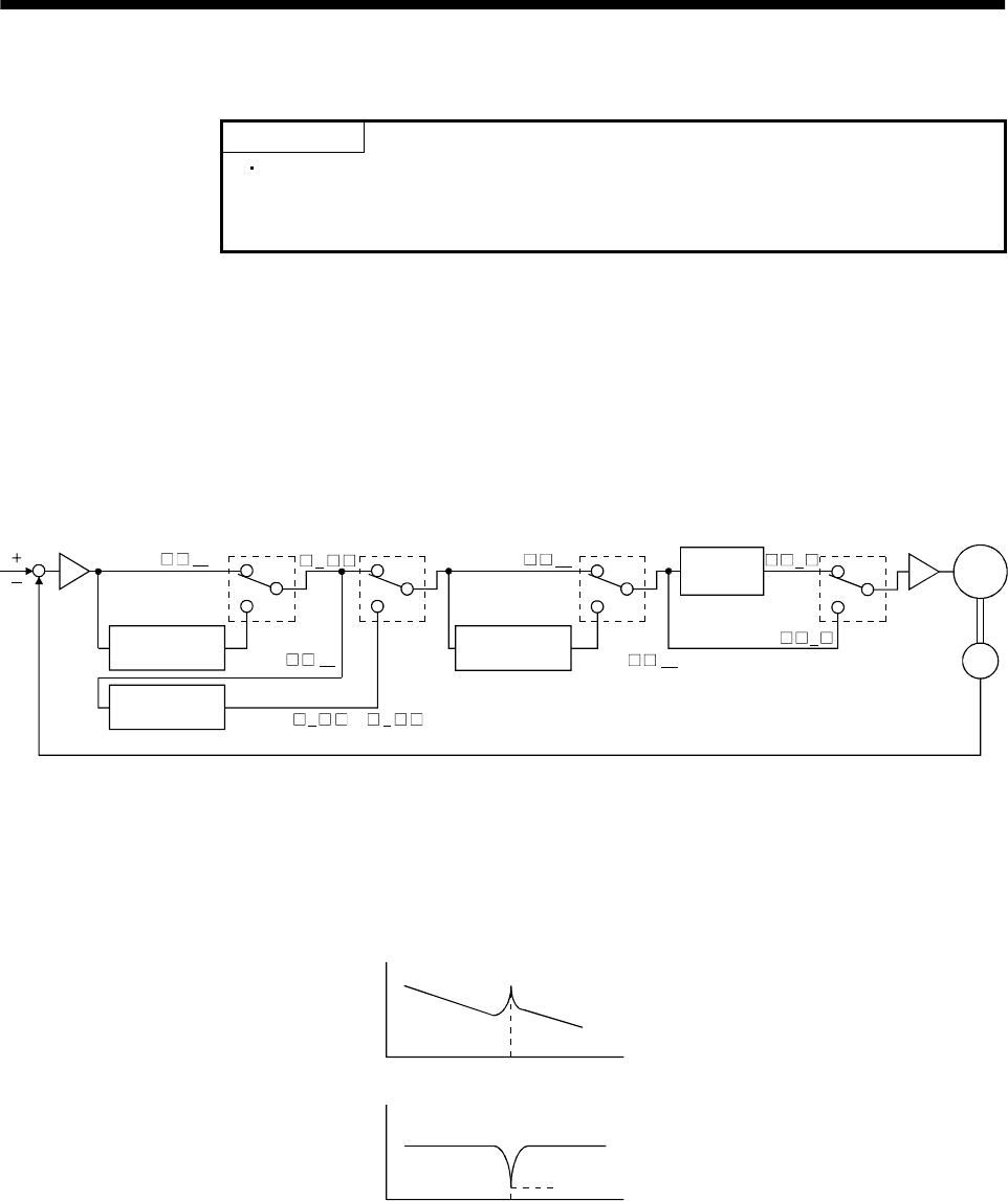
8 - 1
8. SPECIAL ADJUSTMENT FUNCTIONS
8. SPECIAL ADJUSTMENT FUNCTIONS
POINT
The functions given in this chapter need not be used generally. Use them
if you are not satisfied with the machine status after making adjustment
in the methods in Chapter 7.
If a mechanical system has a natural resonance point, increasing the servo system response level may
cause the mechanical system to produce resonance (vibration or unusual noise) at that resonance
frequency.
Using the machine resonance suppression filter and adaptive vibration suppression control functions can
suppress the resonance of the mechanical system.
8.1 Function block diagram
Speed
control
Machine resonance
suppression filter 2
Encoder
Current
command
Low-pass
filter
Parameter
No.58
Parameter
No.60 Parameter
No.59 Parameter
No.60
Machine resonance
suppression filter 1
Adaptive vibration
suppression control
00
or1 2
000 0
1
00
except 00
except
Servo
motor
8.2 Machine resonance suppression filter
(1) Function
The machine resonance suppression filter is a filter function (notch filter) which decreases the gain of
the specific frequency to suppress the resonance of the mechanical system. You can set the gain
decreasing frequency (notch frequency) and gain decreasing depth.
Mechanical
system
response
level
Machine resonance point
Frequency
Notch
depth
Notch frequency Frequency
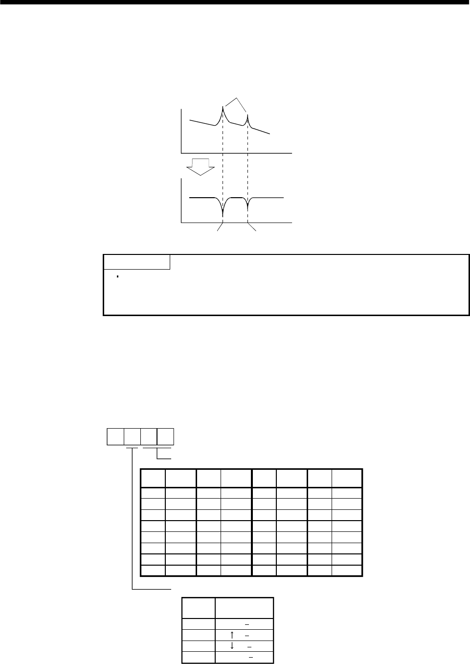
8 - 2
8. SPECIAL ADJUSTMENT FUNCTIONS
You can use the machine resonance suppression filter 1 (parameter No. 58) and machine resonance
suppression filter 2 (parameter No. 59) to suppress the vibration of two resonance frequencies. Note
that if adaptive vibration suppression control is made valid, the machine resonance suppression filter
1 (parameter No. 58) is made invalid.
Mechanical
system
response
level
Machine resonance point
Frequency
Notch
depth
Parameter No. 58 Parameter No. 59
Frequency
POINT
The machine resonance suppression filter is a delay factor for the servo
system. Hence, vibration may increase if you set a wrong resonance
frequency or a too deep notch.
(2) Parameters
(a) Machine resonance suppression filter 1 (parameter No. 58)
Set the notch frequency and notch depth of the machine resonance suppression filter 1 (parameter
No. 58)
When you have made adaptive vibration suppression control selection (parameter No. 60) "valid" or
"held", make the machine resonance suppression filter 1 invalid (parameter No. 58: 0000).
3
1
2
0 ( 14dB)
( 8dB)
00
01
02
03
04
05
06
07
Invalid
4500
2250
08
09
0A
0B
0C
0D
0E
0F
10
11
12
13
14
15
16
17
18
19
1A
1B
1C
1D
1E
1F
1500
1125
900
750
642.9
500
450
409.1
375
346.2
321.4
300
562.5 281.3
264.7
250
236.8
225
214.3
204.5
195.7
187.5
180
173.1
166.7
160.1
155.2
150
145.2
Frequency
Setting
value Frequency Frequency Frequency
Parameter No. 58
Notch frequency
Notch depth
Setting
value Depth (Gain)
Deep ( 40dB)
Shallow( 4dB)
Setting
value Setting
value Setting
value
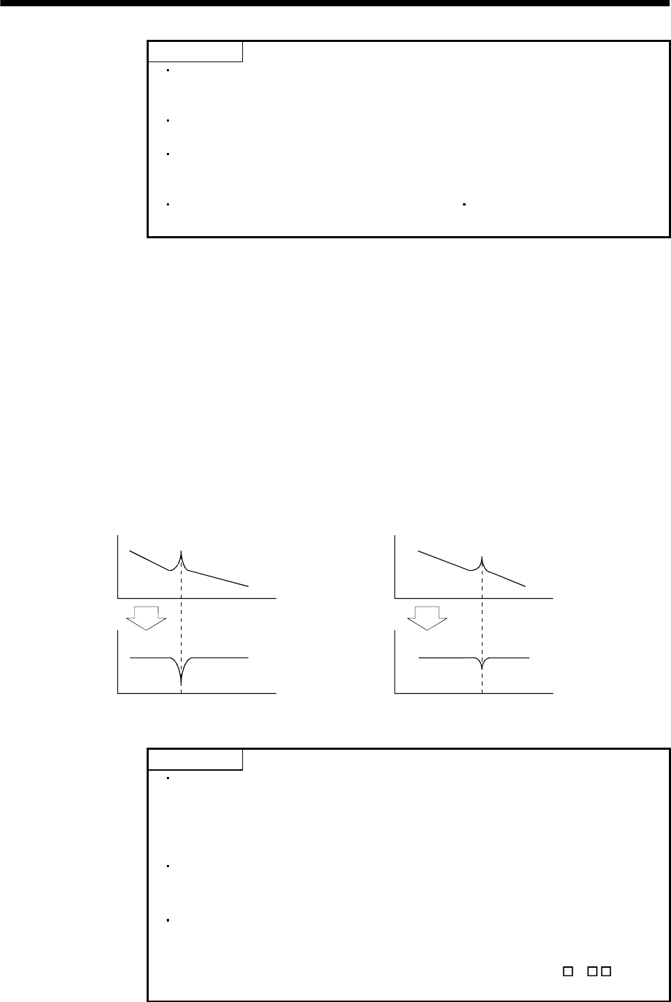
8 - 3
8. SPECIAL ADJUSTMENT FUNCTIONS
POINT
If the frequency of machine resonance is unknown, decrease the notch
frequency from higher to lower ones in order. The optimum notch
frequency is set at the point where vibration is minimal.
A deeper notch has a higher effect on machine resonance suppression but
increases a phase delay and may increase vibration.
The machine characteristic can be grasped beforehand by the machine
analyzer on the MR Configurator (servo configuration software). This
allows the required notch frequency and depth to be determined.
Resonance may occur if parameter No. 58 59 is used to select a close
notch frequency and set a deep notch.
(b) Machine resonance suppression filter 2 (parameter No. 59)
The setting method of machine resonance suppression filter 2 (parameter No. 59) is the same as
that of machine resonance suppression filter 1 (parameter No. 58). However, the machine
resonance suppression filter 2 can be set independently of whether adaptive vibration suppression
control is valid or invalid.
8.3 Adaptive vibration suppression control
(1) Function
Adaptive vibration suppression control is a function in which the servo amplifier detects machine
resonance and sets the filter characteristics automatically to suppress mechanical system vibration.
Since the filter characteristics (frequency, depth) are set automatically, you need not be conscious of
the resonance frequency of a mechanical system. Also, while adaptive vibration suppression control is
valid, the servo amplifier always detects machine resonance, and if the resonance frequency changes,
it changes the filter characteristics in response to that frequency.
Mechanical
system
response
level
Mechanical
system
response
level
Machine resonance point Machine resonance point
Frequency Frequency
Notch
depth Notch
depth
Notch frequency Notch frequency
Frequency Frequency
When machine resonance is large and frequency is low When machine resonance is small and frequency is high
POINT
The machine resonance frequency which adaptive vibration suppression
control can respond to is about 150 to 500Hz. Adaptive vibration
suppression control has no effect on the resonance frequency outside this
range. Use the machine resonance suppression filter for the machine
resonance of such frequency.
Adaptive vibration suppression control may provide no effect on a
mechanical system which has complex resonance characteristics or which
has too large resonance.
Under operating conditions in which sudden disturbance torque is imposed
during operation, the detection of the resonance frequency may malfunction
temporarily, causing machine vibration. In such a case, set adaptive
vibration suppression control to be "held" (parameter No. 60: 2 ) to fix
the characteristics of the adaptive vibration suppression control filter.
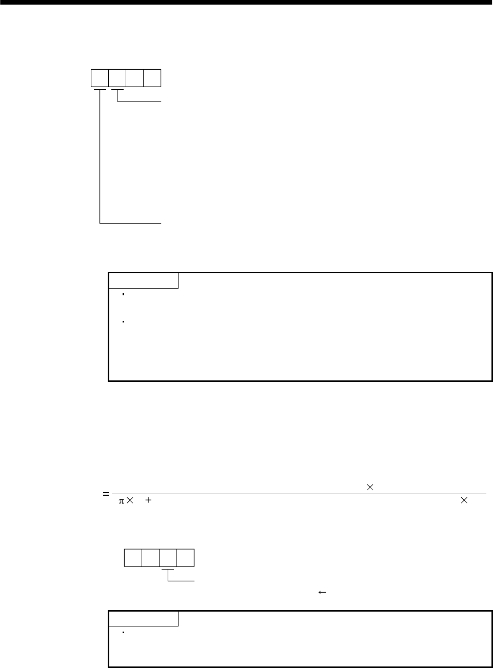
8 - 4
8. SPECIAL ADJUSTMENT FUNCTIONS
(2) Parameters
The operation of adaptive vibration suppression control selection (parameter No.60).
Parameter No. 60
Adaptive vibration suppression control selection
Choosing "valid" or "held" in adaptive vibration suppression
control selection makes the machine resonance suppression
filter 1 (parameter No. 58) invalid.
0: Invalid
1: Valid
Machine resonance frequency is always detected to
generate the filter in response to resonance, suppressing
machine vibration.
2: Held
Adaptive vibration suppression control sensitivity selection
Set the sensitivity of detecting machine resonance.
0: Normal
1: Large sensitivity
Filter characteristics generated so far is held, and detection o
f
machine resonance is stopped.
POINT
Adaptive vibration suppression control is factory-set to be invalid
(parameter No. 60: 0000).
Setting the adaptive vibration suppression control sensitivity can change
the sensitivity of detecting machine resonance. Setting of "large sensitivity"
detects smaller machine resonance and generates a filter to suppress
machine vibration. However, since a phase delay will also increase, the
response of the servo system may not increase.
8.4 Low-pass filter
(1) Function
When a ballscrew or the like is used, resonance of high frequency may occur as the response level of
the servo system is increased. To prevent this, the low-pass filter is factory-set to be valid for a torque
command. The filter frequency of this low-pass filter is automatically adjusted to the value in the
following expression:
Filter frequency(Hz) (1 Ratio of load inertia moment to servo motor inertia moment setting 0.1)
2Speed control gain 2 setting 10
(2) Parameter
Set the operation of the low-pass filter (parameter No. 60.)
Parameter No. 60
Low-pass filter selection
0: Valid (automatic adjustment) initial value
1: Invalid
POINT
In a mechanical system where rigidity is extremely high and resonance is
difficult to occur, setting the low-pass filter to be "invalid" may increase
the servo system response level to shorten the settling time.
8 - 5
8. SPECIAL ADJUSTMENT FUNCTIONS
8.5 Gain changing function
This function can change the gains. You can change between gains during rotation and gains during stop
or can use an external signal to change gains during operation.
8.5.1 Applications
This function is used when:
(1) You want to increase the gains during servo lock but decrease the gains to reduce noise during rotation.
(2) You want to increase the gains during settling to shorten the stop settling time.
(3) You want to change the gains using an external signal to ensure stability of the servo system since the
load inertia moment ratio varies greatly during a stop (e.g. a large load is mounted on a carrier).
8.5.2 Function block diagram
The valid control gains PG2, VG2, VIC and GD2 of the actual loop are changed according to the conditions
selected by gain changing selection CDP (parameter No. 65) and gain changing condition CDS (parameter
No. 66).
Valid
GD2 value
Command pulse
frequency
Droop pulses
Model speed
External signal
CDP
Comparator
Valid
PG2 value
Valid
VG2 value
Valid
VIC value
Changing
PG2 PG2B
100
VIC VICB
100
VG2 VG2B
100
GD2
Parameter No.61
GD2
Parameter No.34
PG2
Parameter No.35
VG2
Parameter No.37
VIC
Parameter No.38
CDP
Parameter No.65
CDS
Parameter No.66

8 - 6
8. SPECIAL ADJUSTMENT FUNCTIONS
8.5.3 Parameters
When using the gain changing function, always set " 4 " in parameter No.2 (auto tuning) to choose
the manual mode of the gain adjustment modes. The gain changing function cannot be used in the auto
tuning mode.
Parameter
No.
Abbrevi
ation Name Unit Description
6 PG1 Position control gain 1 rad/s
36 VG1 Speed control gain 1 rad/s Position and speed gains of a model used to set the response
level to a command. Always valid.
34 GD2 Ratio of load inertia moment to
servo motor inertia moment 0.1
times
35 PG2 Position control gain 2 rad/s
37 VG2 Speed control gain 2 rad/s
38 VIC Speed integral compensation ms
Control parameters before changing
61 GD2B Ratio of load inertia moment to
servo motor inertia moment 2 0.1
times Used to set the ratio of load inertia moment to servo motor
inertia moment after changing.
62 PG2B Position control gain 2 changing
ratio %Used to set the ratio (%) of the after-changing position
control gain 2 to position control gain 2.
63 VG2B Speed control gain 2 changing
ratio %Used to set the ratio (%) of the after-changing speed control
gain 2 to speed control gain 2.
64 VICB Speed integral compensation
changing ratio %Used to set the ratio (%) of the after-changing speed integral
compensation to speed integral compensation.
65 CDP Gain changing selection Used to select the changing condition.
66 CDS Gain changing condition kpps
pulse
r/min
Used to set the changing condition values.
67 CDT Gain changing time constant ms You can set the filter time constant for a gain change at
changing.
8 - 7
8. SPECIAL ADJUSTMENT FUNCTIONS
(1) Parameters No. 6, 34 to 38
These parameters are the same as in ordinary manual adjustment. Gain changing allows the values of
ratio of load inertia moment to servo motor inertia moment, position control gain 2, speed control gain
2 and speed integral compensation to be changed.
(2) Ratio of load inertia moment to servo motor inertia moment 2 (GD2B: parameter No. 61)
Set the ratio of load inertia moment to servo motor inertia moment after changing. If the load inertia
moment ratio does not change, set it to the same value as ratio of load inertia moment to servo motor
inertia moment (parameter No. 34).
(3) Position control gain 2 changing ratio (parameter No. 62), speed control gain 2 changing ratio (parameter
No. 63), speed integral compensation changing ratio (parameter No. 64)
Set the values of after-changing position control gain 2, speed control gain 2 and speed integral
compensation in ratio (%). 100% setting means no gain change.
For example, at the setting of position control gain 2 100, speed control gain 2 2000, speed integral
compensation 20 and position control gain 2 changing ratio 180%, speed control gain 2 changing
ratio 150% and speed integral compensation changing ratio 80%, the after-changing values are as
follows:
Position control gain 2 Position control gain 2 Position control gain 2 changing ratio /100 180rad/s
Speed control gain 2 Speed control gain 2 Speed control gain 2 changing ratio /100 3000rad/s
Speed integral compensation Speed integral compensation Speed integral compensation changing
ratio /100 16ms
(4) Gain changing selection (parameter No. 65)
Used to set the gain changing condition. Choose the changing condition in the first digit. If you set "1"
here, you can use the gain changing (CDP) external input signal for gain changing. The gain changing
(CDP) can be assigned to the pins using parameters No. 43 to 48.
Parameter No. 65
Gain changing selection
Gains are changed in accordance with the settings of
parameters No. 61 to 64 under any of the following conditions:
0: Invalid
1: Gain changing (CDP) input is ON
2: Command frequency is equal to higher than parameter No. 66 setting
3: Droop pulse value is equal to higher than parameter No. 66 setting
4: Servo motor speed is equal to higher than parameter No. 66 setting
(5) Gain changing condition (parameter No. 66)
When you selected "command frequency", "droop pulses" or "servo motor speed" in gain changing
selection (parameter No.65), set the gain changing level.
The setting unit is as follows:
Gain changing condition Unit
Command frequency kpps
Droop pulses pulse
Servo motor speed r/min
(6) Gain changing time constant (parameter No. 67)
You can set the primary delay filter to each gain at gain changing. This parameter is used to suppress
shock given to the machine if the gain difference is large at gain changing, for example.
8 - 8
8. SPECIAL ADJUSTMENT FUNCTIONS
8.5.4 Gain changing operation
This operation will be described by way of setting examples.
(1) When you choose changing by external input
(a) Setting
Parameter No. Abbreviation Name Setting Unit
6 PG1 Position control gain 1 100 rad/s
36 VG1 Speed control gain 1 1000 rad/s
34 GD2 Ratio of load inertia moment to
servo motor inertia moment 40.1 times
35 PG2 Position control gain 2 120 rad/s
37 VG2 Speed control gain 2 3000 rad/s
38 VIC Speed integral compensation 20 ms
61 GD2B Ratio of load inertia moment to
servo motor inertia moment 2 100 0.1 times
62 PG2B Position control gain 2
changing ratio 70 %
63 VG2B Speed control gain 2 changing
ratio 133 %
64 VICB Speed integral compensation
changing ratio 250 %
65 CDP Gain changing selection 0001
(Changed by ON/OFF of
pin CN1A-8)
67 CDT Gain changing time constant 100 ms
(b) Changing operation
OFF ON OFF
Gain changing
(CDP)
Change of
each gain
Before-changing gain
After-changing gain
CDT 100ms
Position control gain 1 100
Speed control gain 1 1000
Ratio of load inertia moment
to servo motor inertia moment 4.0 10.0 4.0
Position control gain 2 120 84 120
Speed control gain 2 3000 4000 3000
Speed integral compensation 20 50 20
8 - 9
8. SPECIAL ADJUSTMENT FUNCTIONS
(2) When you choose changing by droop pulses
(a) Setting
Parameter No. Abbreviation Name Setting Unit
6 PG1 Position control gain 1 100 rad/s
36 VG1 Speed control gain 1 1000 rad/s
34 GD2 Ratio of load inertia moment to
servo motor inertia moment 40 0.1 times
35 PG2 Position control gain 2 120 rad/s
37 VG2 Speed control gain 2 3000 rad/s
38 VIC Speed integral compensation 20 ms
61 GD2B Ratio of load inertia moment to
servo motor inertia moment 2 100 0.1 times
62 PG2B Position control gain 2
changing ratio 70 %
63 VG2B Speed control gain 2 changing
ratio 133 %
64 VICB Speed integral compensation
changing ratio 250 %
65 CDP Gain changing selection 0003
(Changed by droop pulses)
66 CDS Gain changing condition 50 pulse
67 CDT Gain changing time constant 100 ms
(b) Changing operation
CDT 100ms
0
Droop pulses [pulses]
Change of each gain
CDS
CDS
Before-changing gain
After-changing gain
Command pulse Droop pulses
Position control gain 1 100
Speed control gain 1 1000
Ratio of load inertia moment
to servo motor inertia moment 4.0 10.0 4.0 10.0
Position control gain 2 120 84 120 84
Speed control gain 2 3000 4000 3000 4000
Speed integral compensation 20 50 20 50

8 - 10
8. SPECIAL ADJUSTMENT FUNCTIONS
MEMO
9 - 1
9. INSPECTION
9. INSPECTION
WARNING
Before starting maintenance and/or inspection, make sure that the charge lamp is
off more than 15 minutes after power-off. Then, confirm that the voltage is safe in
the tester or the like. Otherwise, you may get an electric shock.
Any person who is involved in inspection should be fully competent to do the work.
Otherwise, you may get an electric shock. For repair and parts replacement,
contact your safes representative.
POINT
Do not test the servo amplifier with a megger (measure insulation
resistance), or it may become faulty.
Do not disassemble and/or repair the equipment on customer side.
(1) Inspection
It is recommended to make the following checks periodically:
(a) Check for loose terminal block screws. Retighten any loose screws.
(b) Check the cables and the like for scratches and cracks. Perform periodic inspection according to
operating conditions.
(2) Life
The following parts must be changed periodically as listed below. If any part is found faulty, it must be
changed immediately even when it has not yet reached the end of its life, which depends on the
operating method and environmental conditions. For parts replacement, please contact your sales
representative.
Part name Life guideline
Smoothing capacitor 10 years
Relay Number of power-on and number of
emergency stop times : 100,000 times
Cooling fan 10,000 to 30,000hours (2 to 3 years)
Servo amplifier
Absolute position battery Refer to Section 15.2
(a) Smoothing capacitor
Affected by ripple currents, etc. and deteriorates in characteristic. The life of the capacitor greatly
depends on ambient temperature and operating conditions. The capacitor will reach the end of its
life in 10 years of continuous operation in normal air-conditioned environment.
(b) Relays
Their contacts will wear due to switching currents and contact faults occur. Relays reach the end of
their life when the cumulative number of power-on and emergency stop times is 100,000, which
depends on the power supply capacity.
(c) Servo amplifier cooling fan
The cooling fan bearings reach the end of their life in 10,000 to 30,000 hours. Normally, therefore,
the fan must be changed in a few years of continuous operation as a guideline.
It must also be changed if unusual noise or vibration is found during inspection.

9 - 2
9. INSPECTION
MEMO
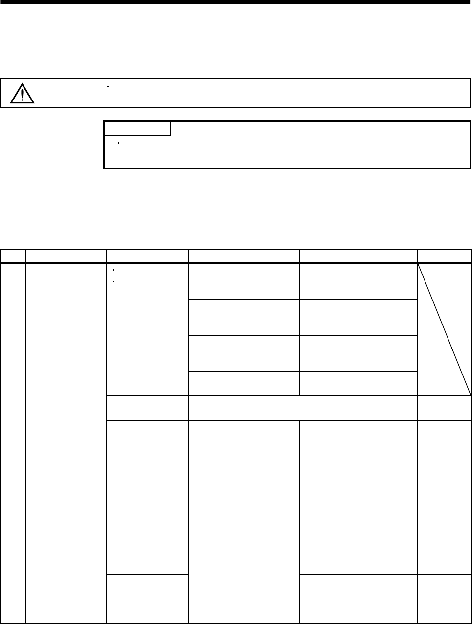
10 - 1
10. TROUBLESHOOTING
10. TROUBLESHOOTING
10.1 Trouble at start-up
CAUTION Excessive adjustment or change of parameter setting must not be made as it will
make operation instable.
POINT
Using the MR Configurator (servo configuration software), you can refer to
unrotated servo motor reasons, etc.
The following faults may occur at start-up. If any of such faults occurs, take the corresponding action.
10.1.1 Position control mode
(1) Troubleshooting
No. Start-up sequence Fault Investigation Possible cause Reference
Not improved if connectors
CN1A, CN1B, CN2 and CN3
are disconnected.
1. Power supply voltage fault
2. Servo amplifier is faulty.
Improved when connectors
CN1A and CN1B are
disconnected.
Power supply of CNP1 cabling
is shorted.
Improved when connector
CN2 is disconnected. 1. Power supply of encoder
cabling is shorted.
2. Encoder is faulty.
LED is not lit.
LED flickers.
Improved when connector
CN3 is disconnected. Power supply of CN3 cabling is
shorted.
1 Power on
Alarm occurs. Refer to Section 10.2 and remove cause. Section 10.2
Alarm occurs. Refer to Section 10.2 and remove cause. Section 10.22 Switch on servo-on
(SON). Servo motor shaft is
not servo-locked
(is free).
1. Check the display to see if
the servo amplifier is
ready to operate.
2. Check the external I/O
signal indication to see if
the servo-on (SON) is ON.
1. Servo-on (SON) is not input.
(Wiring mistake)
2. 24VDC power is not
supplied to COM.
Section 6.6
Servo motor does
not rotate. 1. Wiring mistake
(a) For open collector pulse
train input, 24VDC
power is not supplied to
OPC.
(b) LSP and LSN are not on.
2. No pulses is input.
Section 6.2
3Enter input
command.
(Test operation)
Servo motor run in
reverse direction.
Check cumulative command
pulses.
1. Mistake in wiring to
controller.
2. Mistake in setting of
parameter No. 54.
Chapter 5

10 - 2
10. TROUBLESHOOTING
No. Start-up sequence Fault Investigation Possible cause Reference
Rotation ripples
(speed fluctuations)
are large at low
speed.
Make gain adjustment in the
following procedure:
1. Increase the auto tuning
response level.
2. Repeat acceleration and
deceleration several times
to complete auto tuning.
Gain adjustment fault Chapter 7
4 Gain adjustment
Large load inertia
moment causes the
servo motor shaft to
oscillate side to side.
If the servo motor may be
run with safety, repeat
acceleration and
deceleration several times to
complete auto tuning.
Gain adjustment fault Chapter 7
5 Cyclic operation Position shift occurs Confirm the cumulative
command pulses, cumulative
feedback pulses and actual
servo motor position.
Pulse counting error, etc.
due to noise. (2) in this
section
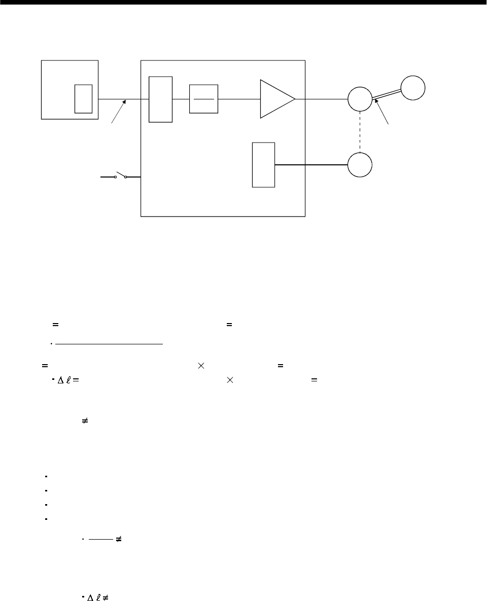
10 - 3
10. TROUBLESHOOTING
(2) How to find the cause of position shift
Positioning unit
(a) Output pulse
counter
QPCMX
CDV
(C) Servo-on (SON),
stroke end
(LSP/LSN) input
(A) (b) Cumulative command
pulses
Electronic gear (parameters No. 3, 4)
C
Servo motor
M
Encoder
L
Machine
(d) Machine stop
position M
(B)
(c) Cumulative
feedback pulses
Servo amplifier
When a position shift occurs, check (a) output pulse counter, (b) cumulative command pulse display, (c)
cumulative feedback pulse display, and (d) machine stop position in the above diagram.
(A), (B) and (C) indicate position shift causes. For example, (A) indicates that noise entered the wiring
between positioning unit and servo amplifier, causing pulses to be mis-counted.
In a normal status without position shift, there are the following relationships:
1) Q P (positioning unit's output counter servo amplifier's cumulative command pulses)
2) CMX(parameter No.3)
CDV(parameter No.4)
P
C (cumulative command pulses electronic gear cumulative feedback pulses)
3) C M (cumulative feedback pulses travel per pulse machine position)
Check for a position shift in the following sequence:
1) When Q P
Noise entered the pulse train signal wiring between positioning unit and servo amplifier,
causing pulses to be miss-counted. (Cause A)
Make the following check or take the following measures:
Check how the shielding is done.
Change the open collector system to the differential line driver system.
Run wiring away from the power circuit.
Install a data line filter. (Refer to (2)(a) Section 13.2.6.)
2) CMX
CDV
P C
When
During operation, the servo-on (SON) or forward/reverse rotation stroke end was switched off or
the clear (CR) and the reset (RES) switched on. (Cause C)
If a malfunction may occur due to much noise, increase the input filter setting (parameter No. 1).
3) When C M
Mechanical slip occurred between the servo motor and machine. (Cause B)

10 - 4
10. TROUBLESHOOTING
10.1.2 Speed control mode
No. Start-up sequence Fault Investigation Possible cause Reference
Not improved if connectors
CN1A, CN1B, CN2 and CN3
are disconnected.
1. Power supply voltage fault
2. Servo amplifier is faulty.
Improved when connectors
CN1A and CN1B are
disconnected.
Power supply of CN1 cabling is
shorted.
Improved when connector
CN2 is disconnected. 1. Power supply of encoder
cabling is shorted.
2. Encoder is faulty.
LED is not lit.
LED flickers.
Improved when connector
CN3 is disconnected. Power supply of CN3 cabling is
shorted.
1 Power on
Alarm occurs. Refer to Section 10.2 and remove cause. Section 10.2
Alarm occurs. Refer to Section 10.2 and remove cause. Section 10.22 Switch on servo-on
(SON). Servo motor shaft is
not servo-locked
(is free).
1. Check the display to see if
the servo amplifier is
ready to operate.
2. Check the external I/O
signal indication to see if
the servo-on (SON) is ON.
1. Servo-on (SON) is not input.
(Wiring mistake)
2. 24VDC power is not
supplied to COM.
Section 6.6
Call the status display and
check the input voltage of
the analog speed command
(VC).
Analog speed command is 0V. Section 6.2
Call the external I/O signal
display and check the
ON/OFF status of the input
signal.
LSP, LSN, ST1 or ST2 is off. Section 6.6
Check the internal speed
commands 1 to 7
(parameters No. 8 to 10 72
to 75).
Set value is 0.
Check the internal torque
limit 1 (parameter No. 28). Torque limit level is too low as
compared to the load torque.
3Switch on forward
rotation start (ST1)
or reverse rotation
start (ST2).
Servo motor does
not rotate.
When the analog torque
limit (TLA) is usable, check
the input voltage on the
status display.
Torque limit level is too low as
compared to the load torque.
(1), Section
5.1.2
Rotation ripples
(speed fluctuations)
are large at low
speed.
Make gain adjustment in the
following procedure:
1. Increase the auto tuning
response level.
2. Repeat acceleration and
deceleration several
times to complete auto
tuning.
Gain adjustment fault Chapter 7
4 Gain adjustment
Large load inertia
moment causes the
servo motor shaft to
oscillate side to side.
If the servo motor may be
run with safety, repeat
acceleration and
deceleration several times to
complete auto tuning.
Gain adjustment fault Chapter 7

10 - 5
10. TROUBLESHOOTING
10.1.3 Torque control mode
No. Start-up sequence Fault Investigation Possible cause Reference
Not improved if connectors
CN1A, CN1B, CN2 and CN3
are disconnected.
1. Power supply voltage fault
2. Servo amplifier is faulty.
Improved when connectors
CN1A and CN1B are
disconnected.
Power supply of CN1 cabling is
shorted.
Improved when connector
CN2 is disconnected. 1. Power supply of encoder
cabling is shorted.
2. Encoder is faulty.
LED is not lit.
LED flickers.
Improved when connector
CN3 is disconnected. Power supply of CN3 cabling is
shorted.
1 Power on
Alarm occurs. Refer to Section 10.2 and remove cause. Section 10.2
Alarm occurs. Refer to Section 10.2 and remove cause. Section 10.22 Switch on servo-on
(SON). Servo motor shaft is
free. Call the external I/O signal
display and check the
ON/OFF status of the input
signal.
1. Servo-on (SON) is not input.
(Wiring mistake)
2. 24VDC power is not
supplied to COM.
Section 6.6
Call the status display and
check the analog torque
command (TC).
Analog torque command is 0V. Section 6.2
Call the external I/O signal
display and check the
ON/OFF status of the input
signal.
RS1 or RS2 is off. Section 6.6
Check the internal speed
limits 1 to 7
(parameters No. 8 to 10 72
to 75).
Set value is 0.
Check the analog torque
command maximum output
(parameter No. 26) value.
Torque command level is too
low as compared to the load
torque.
3Switch on forward
rotation start (RS1)
or reverse rotation
start (RS2).
Servo motor does
not rotate.
Check the internal torque
limit 1 (parameter No. 28). Set value is 0.
(1),
Section 5.1.2
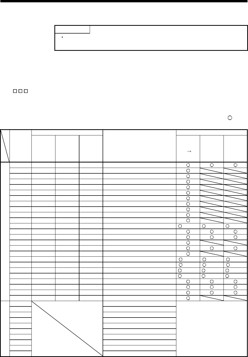
10 - 6
10. TROUBLESHOOTING
10.2 When alarm or warning has occurred
POINT
Configure up a circuit which will detect the trouble (ALM) and turn off the
servo-on (SON) at occurrence of an alarm.
10.2.1 Alarms and warning list
When a fault occurs during operation, the corresponding alarm or warning is displayed. If any alarm or
warning has occurred, refer to Section 10.2.2 or 10.2.3 and take the appropriate action. When an alarm
occurs, ALM turns off.
Set " 1" in parameter No. 49 to output the alarm code in ON/OFF status across the corresponding
pin and SG. Warnings (AL.92 to AL.EA) have no alarm codes. Any alarm code is output at occurrence of
the corresponding alarm. In the normal status, the signals available before alarm code setting (CN1B-19:
ZSP, CN1A-18: INP or SA, CN1A-19: RD) are output.
After its cause has been removed, the alarm can be deactivated in any of the methods marked in the
alarm deactivation column.
(Note 2) Alarm code Alarm deactivation
Display CN1B-19
pin
CN1A-18
pin
CN1A-19
pin
Name Power
OFF ON
Press
"SET" on
current
alarm
screen.
Alarm
reset
(RES)
AL.10010Undervoltage
AL.12 0 0 0 Memory error 1
AL.13 0 0 0 Clock error
AL.15 0 0 0 Memory error 2
AL.16 1 1 0 Encoder error 1
AL.17 0 0 0 Board error
AL.19 0 0 0 Memory error 3
AL.1A 1 1 0 Motor combination error
AL.20 1 1 0 Encoder error 2
AL.24 1 0 0 Main circuit error
AL.25 1 1 0 Absolute position erase
AL.30 0 0 1 Regenerative error (Note 1) (Note 1) (Note 1)
AL.31101Overspeed
AL.32100Overcurrent
AL.33001Overvoltage
AL.35 1 0 1 Command pulse frequency error
AL.37 0 0 0 Parameter error
AL.45 0 1 1 Main circuit device overheat (Note 1) (Note 1) (Note 1)
AL.46 0 1 1 Servo motor overheat (Note 1) (Note 1) (Note 1)
AL.50011Overload 1 (Note 1) (Note 1) (Note 1)
AL.51011Overload 2 (Note 1) (Note 1) (Note 1)
AL.52 1 0 1 Error excessive
AL.8A 0 0 0 Serial communication time-out error
AL.8E 0 0 0 Serial communication error
Alarms
88888 0 0 0 Watchdog
AL.92 Open battery cable warning
AL.96 Home position setting warning
AL.9F Battery warning
AL.E0 Excessive regenerative warning
AL.E1 Overload warning
AL.E3 Absolute position counter warning
AL.E5 ABS time-out warning
AL.E6 Servo emergency stop warning
AL.E9 Main circuit off warning
Warnings
AL.EA ABS servo-on warning
Removing the cause of occurrence
deactivates the alarm
automatically.
Note 1. Deactivate the alarm about 30 minutes of cooling time after removing the cause of occurrence.
2. 0: off
1: on
10 - 7
10. TROUBLESHOOTING
10.2.2 Remedies for alarms
CAUTION
When any alarm has occurred, eliminate its cause, ensure safety, then reset the
alarm, and restart operation. Otherwise, injury may occur.
If an absolute position erase (AL.25) occurred, always make home position setting
again. Otherwise, misoperation may occur.
As soon as an alarm occurs, turn off Servo-on (SON) and power off the main
circuit.
POINT
When any of the following alarms has occurred, always remove its cause
and allow about 30 minutes for cooling before resuming operation. If
operation is resumed by switching control circuit power off, then on to reset
the alarm, the servo amplifier and servo motor may become faulty.
Regenerative error (AL.30)
Overload 1 (AL.50)
Overload 2 (AL.51)
The alarm can be deactivated by switching power off, then on press the
"SET" button on the current alarm screen or by turning on the reset (RES).
For details, refer to Section 10.2.1.
When an alarm occurs, the trouble (ALM) switches off and the dynamic brake is operated to stop the
servomotor. At this time, the display indicates the alarm No.
The servo motor comes to a stop. Remove the cause of the alarm in accordance with this section. The
optional MR Configurator (servo configuration software) may be used to refer to the cause.
Display Name Definition Cause Action
1. Power supply voltage is low.
2. There was an instantaneous
control power failure of 60ms or
longer.
3. Shortage of power supply capacity
caused the power supply voltage to
drop at start, etc.
4. The bus voltage dropped to
200VDC.
Review the power supply.
AL.10 Undervoltage Power supply
voltage dropped.
MR-J2S- A:
160VAC or less
MR-J2S- A1:
83VAC or less
5. Faulty parts in the servo amplifier
Checking method
Alarm (AL.10) occurs if power is
switched on after disconnection
of all cables but the control
circuit power supply cables.
Change the servo amplifier.
AL.12 Memory error 1 RAM, memory fault
AL.13 Clock error Printed board fault Faulty parts in the servo amplifier
Checking method
Alarm (any of AL.11 and AL.13)
occurs if power is switched on
after disconnection of all cables
but the control circuit power
supply cables.
Change the servo amplifier.

10 - 8
10. TROUBLESHOOTING
Display Name Definition Cause Action
1. Faulty parts in the servo amplifier
Checking method
Alarm (AL.15)
occurs if power is switched on
after disconnection of all cables
but the control circuit power
supply cables.
AL.15 Memory error 2 EEP-ROM fault
2. The number of write times to EEP-
ROM exceeded 100,000.
Change the servo amplifier.
1. Encoder connector (CN2)
disconnected. Connect correctly.
2. Encoder fault Change the servo motor.
AL.16 Encoder error 1 Communication
error occurred
between encoder
and servo amplifier. 3. Encoder cable faulty
(Wire breakage or shorted) Repair or change cable.
CPU/parts fault 1. Faulty parts in the servo amplifier.
Checking method
Alarm (AL.17) occurs if power is
switched on after disconnection
of all cable but the control circuit
power supply cable.
Change the servo amplifier.
AL.17 Board error 2
The output
terminals U, V, W of
the servo amplifier
and the input
terminals U, V, W of
the servo motor are
not connected.
2. The wiring of U, V, W is
disconnected or not connected. Correctly connect the output terminals U,
V, W of the servo amplifier and the input
terminals U, V, W of the servo motor.
AL.19 Memory error 3 ROM memory fault Faulty parts in the servo amplifier.
Checking method
Alarm (AL.19) occurs if power is
switched on after disconnection
of all cable but the control circuit
power supply cable.
Change the servo amplifier.
AL.1A Motor
combination
error
Wrong combination
of servo anplifier
and servo motor.
Wrong combination of servo amplifier
and servo motor connected. Use correct combination.
1. Encoder connector (CN2)
disconnected. Connect correctly.
2. Encoder cable faulty
(Wire breakage or shorted) Repair or change the cable.
AL.20 Encoder error 2 Communication
error occurred
between encoder
and servo amplifier. 3. Encoder fault Change the servo motor.
1. Power input wires and servo motor
output wires are in contact at
main circuit terminal block (TE1).
Connect correctly.
2. Sheathes of servo motor power
cables deteriorated, resulting in
ground fault.
Change the cable.
AL.24 Main circuit
error Ground fault
occurred at the
servo motor outputs
(U,V and W phases)
of the servo
amplififer. 3. Main circuit of servo amplifier
failed. Checking method
AL.24 occurs if the servo is
switched on after disconnecting
the U, V, W power cables from
the servo amplifier.
Change the servo amplifier.
10 - 9
10. TROUBLESHOOTING
Display Name Definition Cause Action
1. Reduced voltage of super capacitor
in encoder After leaving the alarm occurring for a few
minutes, switch power off, then on again.
Always make home position setting again.
2. Battery voltage low
Absolute position
data in error
3. Battery cable or battery is faulty. Change battery.
Always make home position setting again.
AL.25 Absolute
position erase
Power was switched
on for the first time
in the absolute
position detection
system.
4. Super capacitor of the absolute
position encoder is not charged After leaving the alarm occurring for a few
minutes, switch power off, then on again.
Always make home position setting again.
1. Wrong setting of parameter No. 0 Set correctly.
2. Built-in regenerative brake
resistor or regenerative brake
option is not connected.
Connect correctly
3. High-duty operation or continuous
regenerative operation caused the
permissible regenerative power of
the regenerative brake option to
be exceeded.
Checking method
Call the status display and check
the regenerative load ratio.
1. Reduce the frequency of positioning.
2. Use the regenerative brake option of
larger capacity.
3. Reduce the load.
4. Power supply voltage is abnormal.
MR-J2S- A:260VAC or more
MR-J2S- A1:135VAC or more
Review power supply
Permissible
regenerative power
of the built-in
regenerative brake
resistor or
regenerative brake
option is exceeded.
5. Built-in regenerative brake
resistor or regenerative brake
option faulty.
Change servo amplifier or regenerative
brake option.
AL.30 Regenerative
alarm
Regenerative
transistor fault 6. Regenerative transistor faulty.
Checking method
1) The regenerative brake option
has overheated abnormally.
2) The alarm occurs even after
removal of the built-in
regenerative brake resistor or
regenerative brake option.
Change the servo amplifier.
1. Input command pulse frequency
exceeded the permissible
instantaneous speed frequency.
Set command pulses correctly.
2. Small acceleration/deceleration
time constant caused overshoot to
be large.
Increase acceleration/deceleration time
constant.
3. Servo system is instable to cause
overshoot. 1. Re-set servo gain to proper value.
2. If servo gain cannot be set to proper
value:
1) Reduce load inertia moment ratio; or
2) Reexamine acceleration/
deceleration time constant.
4. Electronic gear ratio is large
(parameters No. 3, 4) Set correctly.
AL.31 Overspeed Speed has exceeded
the instantaneous
permissible speed.
5. Encoder faulty. Change the servo motor.

10 - 10
10. TROUBLESHOOTING
Display Name Definition Cause Action
1. Short occurred in servo amplifier
output phases U, V and W. Correct the wiring.AL.32 Overcurrent Current that flew is
higher than the
permissible current
of the servo
amplifier.
2. Transistor (IPM) of the servo
amplifier faulty.
Checking method
Alarm (AL.32) occurs if power is
switched on after U,V and W
are disconnected.
Change the servo amplifier.
3. Ground fault occurred in servo
amplifier output phases U, V and
W.
Correct the wiring.
4. External noise caused the
overcurrent detection circuit to
misoperate.
Take noise suppression measures.
Current higher than
the permissible
current flew in the
regenerative brake
transistor.
(MR-J2S-500A only)
5. Improper wiring of the
regenerative brake option. Wire the regenerative brake option
correctly.
1. Regenerative brake option is not
used. Use the regenerative brake option.
2. Though the regenerative brake
option is used, the parameter No.
0 setting is " 00 (not used)".
Make correct setting.
3. Lead of built-in regenerative brake
resistor or regenerative brake
option is open or disconnected.
1. Change lead.
2. Connect correctly.
4. Regenerative transistor faulty. Change servo amplifier
5. Wire breakage of built-in
regenerative brake resistor or
regenerative brake option
1. For wire breakage of built-in
regenerative brake resistor, change
servo amplifier.
2. For wire breakage of regenerative brake
option, change regenerative brake
option.
6. Capacity of built-in regenerative
brake resistor or regenerative
brake option is insufficient.
Add regenerative brake option or increase
capacity.
7. Power supply voltage high. Review the power supply.
AL.33 Overvoltage Converter bus
voltage exceeded
400VDC.
8. Ground fault occurred in servo
amplifier output phases U, V and
W.
Correct the wiring.
1. Pulse frequency of the command
pulse is too high. Change the command pulse frequency to a
proper value.
2. Noise entered command pulses. Take action against noise.
AL.35 Command
pulse frequency
error
Input pulse
frequency of the
command pulse is
too high. 3. Command device failure Change the command device.
1. Servo amplifier fault caused the
parameter setting to be rewritten. Change the servo amplifier.
2. Regenerative brake option not
used with servo amplifier was
selected in parameter No.0.
Set parameter No.0 correctly.
3. The number of write times to EEP-
ROM exceeded 100,000 due to
parameter write, etc.
Change the servo amplifier.
4.The alarm code output (parameter
No. 49) was set by the absolute
position detection system.
The absolute position detection system
and the alarm code output function are
exclusive. Set as either one of the two is
used.
AL.37 Parameter
error Parameter setting is
wrong.
5.The alarm code output (parameter
No.49) was set with the
electromagnetic brake interlock
(MBR) assigned to pin CN1B-19.
The signal assignment function of the
electromagnetic interlock (MBR) to pin
CN1B-19 and the alarm code output
function are exclusive. Set as either one of
the two is used.

10 - 11
10. TROUBLESHOOTING
Display Name Definition Cause Action
1. Servo amplifier faulty. Change the servo amplifier.
2. The power supply was turned on
and off continuously by overloaded
status.
The drive method is reviewed.
AL.45 Main circuit
device overheat Main circuit device
overheat
3. Air cooling fan of servo amplifier
stops. 1. Exchange the cooling fan or the servo
amplifier.
2. Reduce ambient temperature.
1. Ambient temperature of servo
motor is over 40 (104 ). Review environment so that ambient
temperature is 0 to 40 (104 ).
2. Servo motor is overloaded. 1. Reduce load.
2. Review operation pattern.
3. Use servo motor that provides larger
output.
AL.46 Servo motor
overheat Servo motor
temperature rise
actuated the
thermal sensor.
3. Thermal sensor in encoder is
faulty. Change servo motor.
1. Servo amplifier is used in excess
of its continuous output current. 1. Reduce load.
2. Review operation pattern.
3. Use servo motor that provides larger
output.
2. Servo system is instable and
hunting. 1. Repeat acceleration/
deceleration to execute auto tuning.
2. Change auto tuning response setting.
3. Set auto tuning to OFF and make gain
adjustment manually.
3. Machine struck something. 1. Review operation pattern.
2. Install limit switches.
4. Wrong connection of servo motor.
Servo amplifier's output terminals
U, V, W do not match servo
motor's input terminals U, V, W.
Connect correctly.
AL.50 Overload 1 Load exceeded
overload protection
characteristic of
servo amplifier.
5. Encoder faulty.
Checking method
When the servo motor shaft is
rotated with the servo off, the
cumulative feedback pulses do
not vary in proportion to the
rotary angle of the shaft but the
indication skips or returns midway.
Change the servo motor.
1. Machine struck something. 1. Review operation pattern.
2. Install limit switches.
2. Wrong connection of servo motor.
Servo amplifier's output terminals
U, V, W do not match servo
motor's input terminals U, V, W.
Connect correctly.
3. Servo system is instable and
hunting. 1. Repeat acceleration/deceleration to
execute auto tuning.
2. Change auto tuning response setting.
3. Set auto tuning to OFF and make gain
adjustment manually.
AL.51 Overload 2 Machine collision or
the like caused max.
output current to
flow successively for
several seconds.
Servo motor locked:
1s or more
During rotation:
2.5s or more
4. Encoder faulty.
Checking method
When the servo motor shaft is
rotated with the servo off, the
cumulative feedback pulses do
not vary in proportion to the
rotary angle of the shaft but the
indication skips or returns midway.
Change the servo motor.

10 - 12
10. TROUBLESHOOTING
Display Name Definition Cause Action
1. Acceleration/deceleration time
constant is too small. Increase the acceleration/deceleration
time constant.
2. Torque limit value (parameter
No.28) is too small. Increase the torque limit value.
3. Motor cannot be started due to
torque shortage caused by power
supply voltage drop.
1. Review the power supply capacity.
2. Use servo motor which provides larger
output.
4. Position control gain 1 (parameter
No.6) value is small. Increase set value and adjust to ensure
proper operation.
5. Servo motor shaft was rotated by
external force. 1. When torque is limited, increase the
limit value.
2. Reduce load.
3. Use servo motor that provides larger
output.
6. Machine struck something. 1. Review operation pattern.
2. Install limit switches.
7. Encoder faulty Change the servo motor.
AL.52 Error excessive
(Note) The difference
between the model
position and the
actual servomotor
position exceeds 2.5
rotations.
(Refer to the
function block
diagram in Section
1.2.)
8. Wrong connection of servo motor.
Servo amplifier's output terminals
U, V, W do not match servo
motor's input terminals U, V, W.
Connect correctly.
1. Communication cable breakage. Repair or change communication cable
2. Communication cycle longer than
parameter No. 56 setting. Set correct value in parameter.
AL.8A Serial
communication
time-out error
RS-232C or RS-422
communication
stopped for longer
than the time set in
parameter No.56. 3. Wrong protocol. Correct protocol.
1. Communication cable fault
(Open cable or short circuit) Repair or change the cable.AL.8E Serial
communication
error
Serial
communication
error occurred
between servo
amplifier and
communication
device (e.g. personal
computer).
2. Communication device (e.g.
personal computer) faulty Change the communication device (e.g.
personal computer).
88888 Watchdog CPU, parts faulty Fault of parts in servo amplifier
Checking method
Alarm (88888) occurs if power
is switched on after disconnection
of all cables but the control circuit
power supply cable.
Change servo amplifier.
Note. The error excessive detection for 2.5 revolutions is available only when the servo amplifier of software version B0 or later is used.
For the servo amplifier of software version older than B0, an error excessive alarm occurs when the deviation (deviation counter
value) between the instructed position and the actual servo motor position exceeds 10 revolutions.
10 - 13
10. TROUBLESHOOTING
10.2.3 Remedies for warnings
CAUTION If an absolute position counter warning (AL.E3) occurred, always make home
position setting again. Otherwise, misoperation may occur.
POINT
When any of the following alarms has occurred, do not resume operation by
switching power of the servo amplifier OFF/ON repeatedly. The servo amplifier
and servo motor may become faulty. If the power of the servo amplifier is
switched OFF/ON during the alarms, allow more than 30 minutes for cooling
before resuming operation.
Excessive regenerative warning (AL.E0)
Overload warning 1 (AL.E1)
If Servo emergency stop warning (AL.E6) or ABS servo-on warning (AL.EA) occurs, the servo off status is
established. If any other warning occurs, operation can be continued but an alarm may take place or
proper operation may not be performed. Use the optional MR Configurator (servo configuration software)
to refer to the cause of warning.
Display Name Definition Cause Action
1. Battery cable is open. Repair cable or changed.AL.92 Open battery
cable warning Absolute position
detection system battery
voltage is low. 2. Battery voltage supplied from the servo
amplifier to the encoder fell to about 3.2V
or less. (Detected with the encoder)
Change battery.
1. Droop pulses remaining are greater
than the in-position range setting. Remove the cause of droop pulse
occurrence
2. Command pulse entered after clearing
of droop pulses. Do not enter command pulse
after clearing of droop pulses.
AL.96 Home position
setting warning Home position setting
could not be made.
3. Creep speed high. Reduce creep speed.
AL.9F Battery warning Voltage of battery for
absolute position
detection system reduced.
Battery voltage fell to 3.2V or less.
(Detected with the servo amplifier) Change the battery.
AL.E0 Excessive
regenerative
warning
There is a possibility that
regenerative power may
exceed permissible
regenerative power of
built-in regenerative
brake resistor or
regenerative brake
option.
Regenerative power increased to 85% or
more of permissible regenerative power of
built-in regenerative brake resistor or
regenerative brake option.
Checking method
Call the status display and check
regenerative load ratio.
1. Reduce frequency of
positioning.
2. Change regenerative brake
option for the one with larger
capacity.
3. Reduce load.
AL.E1 Overload
warning There is a possibility that
overload alarm 1 or 2
may occur.
Load increased to 85% or more of overload
alarm 1 or 2 occurrence level.
Cause, checking method
Refer to AL.50,51.
Refer to AL.50, AL.51.
1. Noise entered the encoder. Take noise suppression
measures.
Absolute position encoder
pulses faulty. 2. Encoder faulty. Change servo motor.
AL.E3 Absolute position
counter warning
The multi-revolution
counter value of the
absolute position encoder
exceeded the maximum
revolution range.
3. The movement amount from the home
position exceeded a 32767 rotation or -
37268 rotation in succession.
Make home position setting
again.

10 - 14
10. TROUBLESHOOTING
Display Name Definition Cause Action
1. PC lader program wrong. Contact the program.AL.E5 ABS time-out
warning 2. Reverse rotation start (ST2) Limiting
torque (TLC) improper wiring Connect properly.
AL.E6 Servo emergency
stop warning EMG is off. External emergency stop was made valid.
(EMG was turned off.) Ensure safety and deactivate
emergency stop.
AL.E9 Main circuit off
warning Servo-on (SON) was
switched on with main
circuit power off.
Switch on main circuit power.
1. PC ladder program wrong. 1. Correct the program.AL.EA ABS
servo-on warning Servo-on (SON) turned on
more than 1s after servo
amplifier had entered
absolute position data
transfer mode.
2. Servo-on (SON) improper wiring. 2. Connect properly.
11 - 1
11. OUTLINE DIMENSION DRAWINGS
11. OUTLINE DIMENSION DRAWINGS
11.1 Servo amplifiers
(1) MR-J2S-10A to MR-J2S-60A
MR-J2S-10A1 to MR-J2S-40A1
E
N
C
()
[Unit: mm]
6 ( 0.24) mounting hole
A Approx.70 (2.76) 135 (5.32)
TE2
4(0.16)
B
168 (6.61)
Approx.7 (0.28)
156 (6.14)
6 (0.24)
6
(0.24)
C
N
1
A
OPEN
L1 L2 L3
UVW
MITSUBISHI
C
N
1
B
C
N
2
E
N
C
C
N
3
([Unit: in])
Terminal layout
(Terminal cover open)
Name plate
PE terminal
(0.79)
6
(0.24)
(Note)
TE1
OPEN
MITSUBISHI
C
N
1
A
C
N
2
C
N
1
B
C
N
3
Approx.
20
Variable dimensions
Servo amplifier AB
Mass
[kg]([lb])
MR-J2S-10A(1)
MR-J2S-20A(1) 50 (1.97) 6 (0.24) 0.7 (1.54)
MR-J2S-40A(1)
MR-J2S-60A 70 (2.76) 22 (0.87) 1.1 (2.43)
Note. This data applies to the 3-phase 200 to 230VAC and 1-phase 230VAC power supply models.
TE2
Front
DCPL
21 L11
PE terminals
Terminal screw: M4
Tightening torque: 1.2 [N m] (10.6 [lb in])
TE1
L1
UVW
Terminal screw: M4
Tightening torque: 1.2 [N m] (10.6 [lb in])
UVW
Terminal screw: M4
Tightening torque: 1.2 [N m] (10.6 [lb in])
For 3-phase 200 to 230VAC and 1-phase 230VAC For 1-phase 100 to 120VAC
L2L3L1L2
Terminal signal layout
Mounting Screw
Screw Size:M5
Tightening torque:
3.24[N m]
(28.676 [lb in])
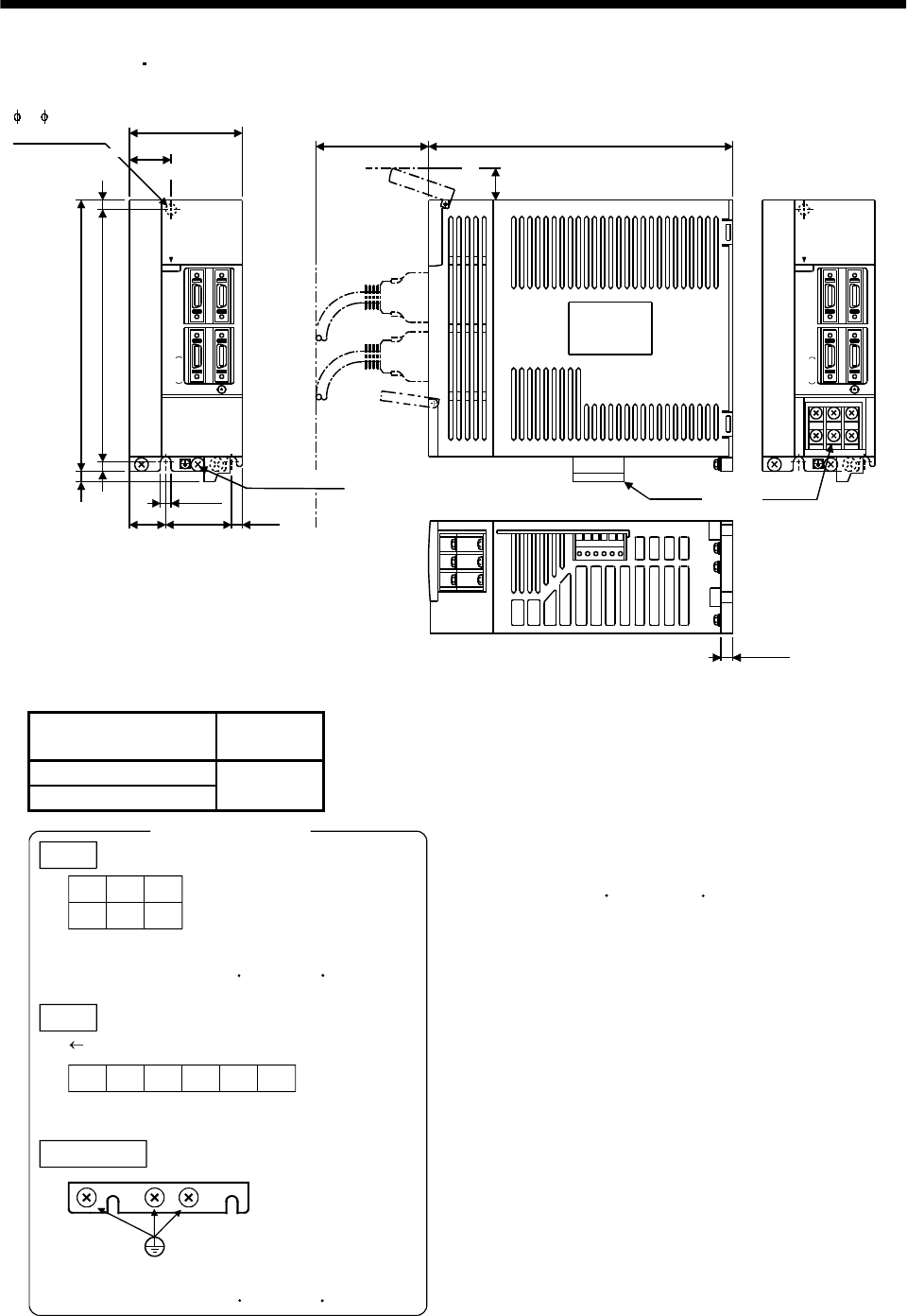
11 - 2
11. OUTLINE DIMENSION DRAWINGS
(2) MR-J2S-70A MR-J2S-100A
C
N
1
A
OPEN
MITSUBISHI
C
N
1
B
C
N
2
E
N
C
C
N
3
Approx.7 (0.28)
C
N
1
A
OPEN
L1 L2 L3
UVW
MITSUBISHI
C
N
1
B
C
N
2
E
N
C
C
N
3
[Unit: mm]
([Unit: in])
Approx.70(2.76)
70(2.76) 190(7.48)
22
TE1
TE2
6(0.24)
(0.79)
Name plate
Terminal layout
(Terminal cover open)
6 ( 0.24)
mounting hole
168(6.61)
156(6.14)
6(0.24)
6(0.24)
42
(1.65)
22
(0.87)
6(0.24)
PE terminal
6
(0.24)
(0.87)
Approx.
20
Servo amplifier Mass
[kg]([lb])
MR-J2S-70A
MR-J2S-100A 1.7
(3.75)
TE1
L1
UVW
Terminal screw: M4
Tightening torque: 1.2 [N m] (10.6 [lb in])
TE2
DCP N
PE terminals
Terminal screw: M4
Tightening torque: 1.2 [N m] (10.6 [lb in])
L2L3
L21 L11
Front
Mounting Screw
Screw Size:M5
Tightening torque:3.24[N m](28.676 [lb in])
Terminal signal layout
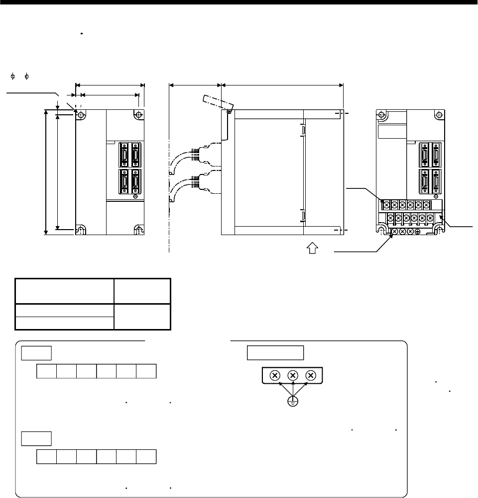
11 - 3
11. OUTLINE DIMENSION DRAWINGS
(3) MR-J2S-200A MR-J2S-350A
MITSUBISHI MITSUBISHI
Approx.70
(2.76) 195(7.68)
90(3.54)
78(3.07)
6
168(6.61)
156(6.14) 6
6 ( 0.24)
mounting hole
Terminal layout
TE1
[Unit: mm]
([Unit: in])
TE2
PE terminal
(0.24)
(0.24)
Fan air orientation
Servo amplifier Mass
[kg]([lb])
MR-J2S-200A
MR-J2S-350A 2.0
(4.41)
TE1
L1L2L3UVW
L11 L21 DPCN
Terminal screw: M4
Tightening torque: 1.2 [N m] (10.6 [lb in])
Terminal screw: M4
Tightening torque: 1.2 [N m] (10.6 [lb in])
TE2
PE terminals
Terminal screw: M4
Tightening torque: 1.2 [N m] (10.6 [lb in])
Mounting Screw
Screw Size:M5
Tightening torque:
3.24[N m]
(28.676 [lb in])
Terminal signal layout
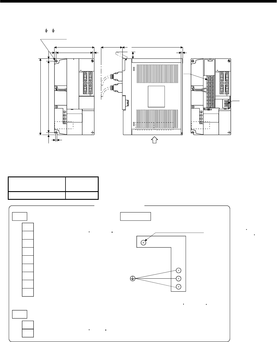
11 - 4
11. OUTLINE DIMENSION DRAWINGS
(4) MR-J2S-500A
[Unit: mm]
([Unit: in])
C
N
2
C
N
3
C
N
1
A
C
N
1
B
OPEN
OPEN
C
N
2
C
N
3
C
N
1
A
C
N
1
B
OPEN
TE1
TE2
2- 6( 0.24)
mounting hole
130(5.12)
118(4.65)
7.5
(0.5)
(0.24)
6 (0.24)
250(9.84)
235(9.25)
7.5
(0.5)
6(0.24)
N.P.
Approx.
70
(2.76)
6
(0.79)
200(7.87)(0.19) 5 Terminal layout
N.P.
Fan Fan
Fan air orientation
MITSUBISHI MITSUBISHI
Approx.20
Servo amplifier Mass
[kg]([lb])
MR-J2S-500A 4.9(10.8)
TE1
TE2
L11
L21
N
L1
L2
L3
C
P
U
V
W
Terminal screw : M4
Tightening torque : 1.2 [N m](10.6[lb in])
PE terminals
Built-in regenerative brake resistor
lead terminal fixing screw
Terminal screw : M4
Tightening torque : 1.2 [N m](10.6[lb in])
Terminal screw : M3.5
Tightening torque : 0.8 [N m](7[lb in])
Mounting Screw
Screw Size:M5
Tightening torque:
3.24[N m]
(28.676 [lb in])
Terminal signal layout
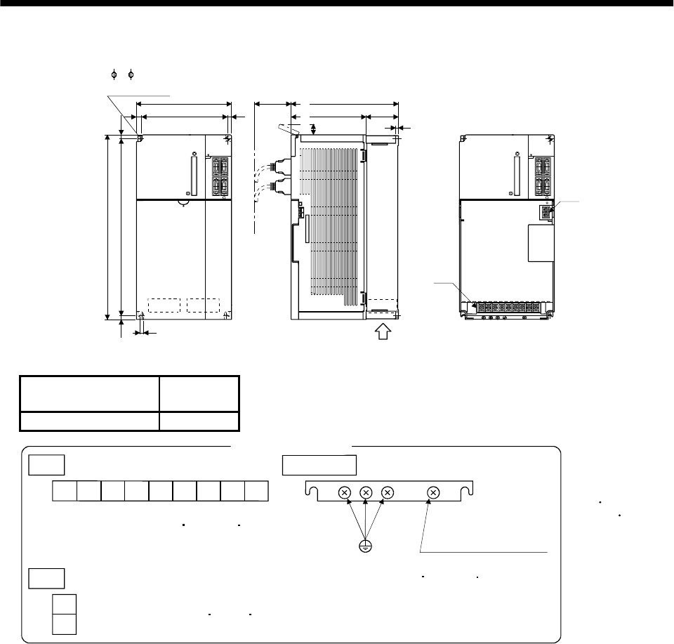
11 - 5
11. OUTLINE DIMENSION DRAWINGS
(5) MR-J2S-700A
C
N
1
B
C
N
1
A
C
N
3
C
N
2TE2
OPEN
C
N
1
B
C
N
1
A
C
N
3
C
N
2
TE1
2- 6( 0.24)
mounting hole
7.5
(0.5)
(0.39)
10
180(7.09)
160(6.23)
(0.39)
10
Approx.70
(2.76)
200(7.87)
138(5.43) 62
(2.44) 6(0.24) Terminal layout
[Unit: mm]
([Unit: in])
(0.79)
350(13.8)
335(13.2)
7.5
(0.5)
6 (0.24)
Fan air orientation
Fan
MITSUB IS HI
OPEN
OPEN
MITSUB IS HI
Approx.20
Servo amplifier Mass
[kg]([lb])
MR-J2S-700A 7.2(15.9)
L1L2L3
TE1
TE2
NPC
L11
L21
WVU
Terminal screw : M4
Tightening torque : 1.2 [N m](10.6[lb in])
Terminal screw : M3.5
Tightening torque : 0.8 [N m](7[lb in])
Terminal screw : M4
Tightening torque : 1.2 [N m](10.6[lb in])
Built-in regenerative
brake resistor
lead terminal fixing screw
PE terminals Mounting Screw
Screw Size:M5
Tightening torque:
3.24[N m]
(28.676 [lb in])
Terminal signal layout
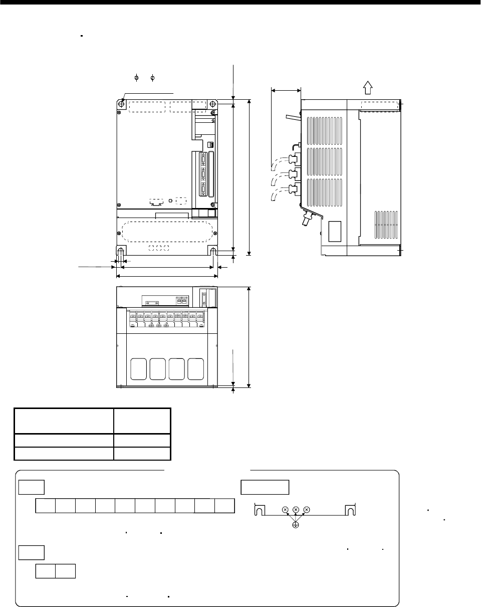
11 - 6
11. OUTLINE DIMENSION DRAWINGS
(6) MR-J2S-11KA 15KA
3.9(0.15)
Fan air orientation
Fan
Approx.
75
(2.95)
12(0.47)
C
N
3
C
N
1
A
C
N
1
B
CN4
MITSU BISHI
TE1
CON2
376(14.8)
400(15.75)
12
12(0.47)
12(0.47)
(0.47)12 236(9.29)
260(10.24)
CHARGE
CN2
TE2
2- 12( 0.47)
mounting hole
(0.47)
[Unit: mm]
([Unit: in])
260(10.24)
Servo amplifier Mass
[kg]([lb])
MR-J2S-11KA 15(33.1)
MR-J2S-15KA 16(35.3)
TE2
L11 L21
Terminal screw : M4
Tightening torque : 1.2[N m] (10.6[lb in])
L1L2L3
TE1
Terminal screw : M6
Tightening torque : 3.0[N m] (26[lb in)]
WVU CPP1N
PE terminal
Terminal screw : M6
Tightening torque : 6.0[N m] (52[lb in)]
Mounting Screw
Screw Size:M10
Tightening torque:
26.5[N m]
(234.545[lb in])
Terminal signal layout
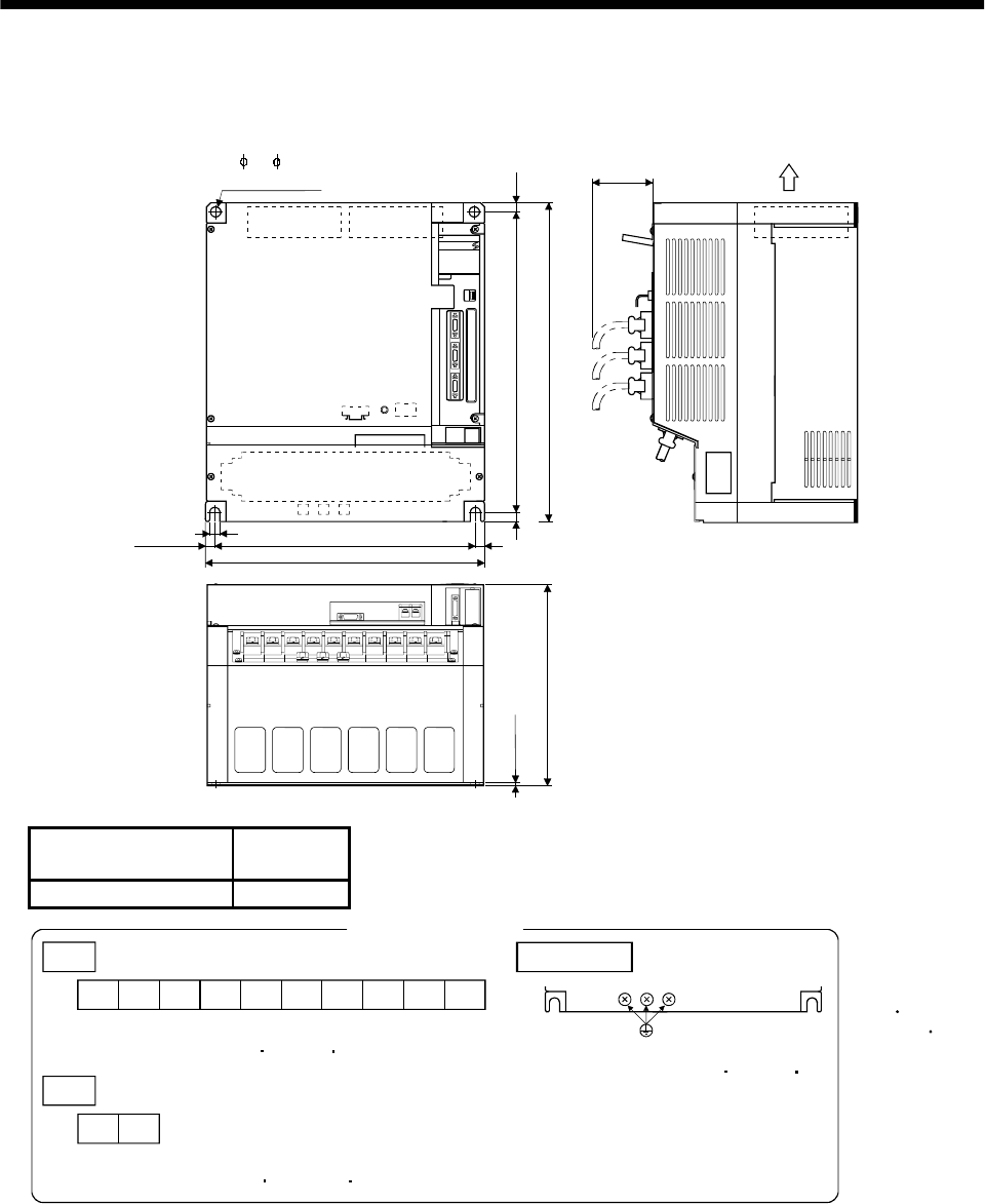
11 - 7
11. OUTLINE DIMENSION DRAWINGS
(7) MR-J2S-22KA
3.9(0.15)
Fan air orientation
Fan
[Unit: mm]
([Unit: in])
Approx.
75
(2.95)
C
N
3
C
N
1
A
C
N
1
B
CN4
MITSUBISHI
TE1
CON2
12(0.47)
326(12.84)
376(14.8)
400(15.75)
12
350(13.78)
12(0.47)
12(0.47)
(0.47)12
CHARGE
CN2
TE2
2- 12( 0.47)
mounting hole
(0.47)
260(0.24)
Servo amplifier Mass
[kg]([lb])
MR-J2S-22KA 20(44.1)
TE2
L11 L21
Terminal screw : M4
Tightening torque : 1.2[N m] (10.6[lb in)]
L1L2L3
TE1
WVU CPP1N
Terminal screw : M8
Tightening torque : 6.0[N m] (52[lb in)]
PE terminal
Terminal screw : M8
Tightening torque : 6.0[N m] (52[lb in)]
Mounting Screw
Screw Size:M10
Tighting torque:
26.5[N m]
(234.545[lb in])
Terminal signal layout
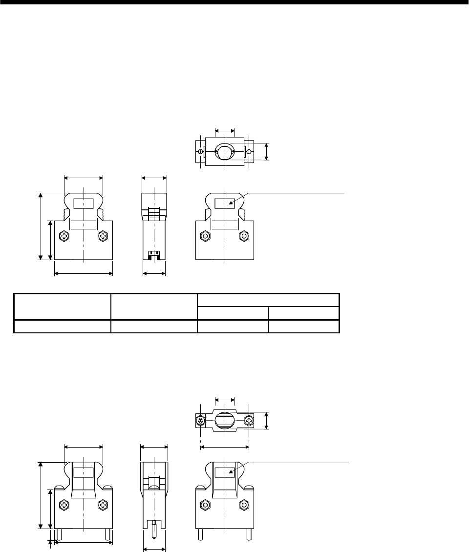
11 - 8
11. OUTLINE DIMENSION DRAWINGS
11.2 Connectors
(1) Servo amplifier side
<3M>
(a) Soldered type
Model
Connector : 10120-3000VE
Shell kit : 10320-52F0-008 12.0(0.47)
B
A
23.8(0.94)
39.0(1.54)
12.7
(0.50)
14.0
(0.55) Logo, etc. are indicated here.
10.0
(0.39)
[Unit: mm]
([Unit: in])
Variable dimensions
Connector Shell kit AB
10120-3000VE 10320-52F0-008 22.0(0.87) 33.3(1.31)
(b) Threaded type
Model
Connector : 10120-3000VE
Shell kit : 10320-52A0-008 12.0(0.47)
33.3
(1.31)
22.0(0.87)
23.8(0.94)
39.0(1.54)
12.7
(0.50)
14.0
(0.55) Logo, etc. are indicated here.
10.0
(0.22)5.7
27.4
(1.08)
[Unit: mm]
([Unit: in])
(0.39)
Note. This is not available as option
and should be user-prepared.
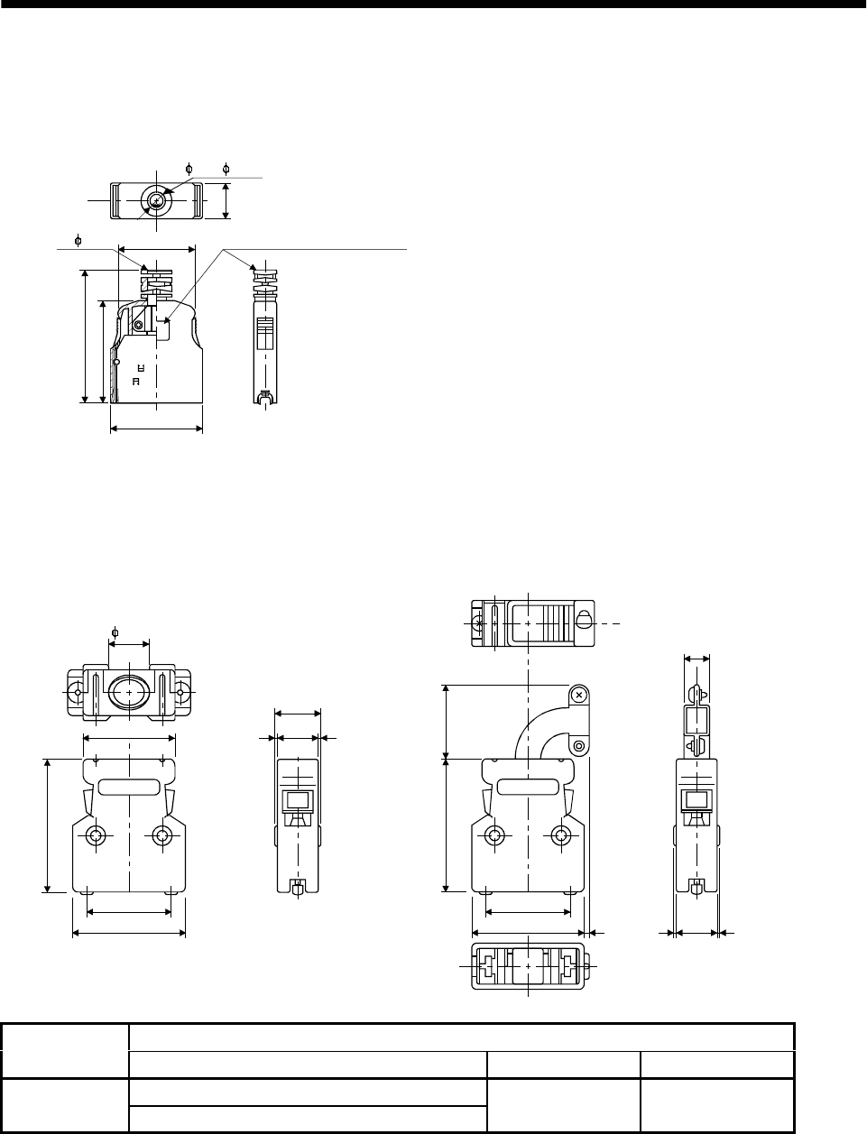
11 - 9
11. OUTLINE DIMENSION DRAWINGS
(c) Insulation displacement type
Model
Connector : 10120-6000EL
Shell kit : 10320-3210-000
33.0(1.30)
42.0(1.65)
29.7
(1.17)
20.9(0.82)
11.5
(0.45)
6.7
Logo, etc. are indicated here.
2- 0.5
(0.02)
[Unit: mm]
([Unit: in])
( 0.26)
(2) Bus cable connector
<Honda Tsushin Industry>
23.0(0.91)
RS
1(0.04)(0.04)1 12.2
(0.48)
14.2(0.56)
38.5
(1.52)
27.4(1.08)
32.0(0.91)
HONDA
PCR-LS20LA1
38.5
(1.52)
27.4(1.08)
32.0(0.91)
HONDA
RS
10.4(0.41)
1.9
(0.08)
20.6
(0.81)
112.2
(0.48)
PCR-LS20LA1W
13.0
(0.04) (0.04)
1
[Unit: mm]
([Unit: in])
(0.51)
Model
Number of Pins Connector Case Crimping terminal
PCR-S20FS (soldering type)
20 PCR-S20F (insulation displacement type) PCR-LS20LA1
PCR-LS20LA1W FHAT-002A
Note. PCR-S20F and PCR-LS20LA1W are not options and are to be supplied by the customer.
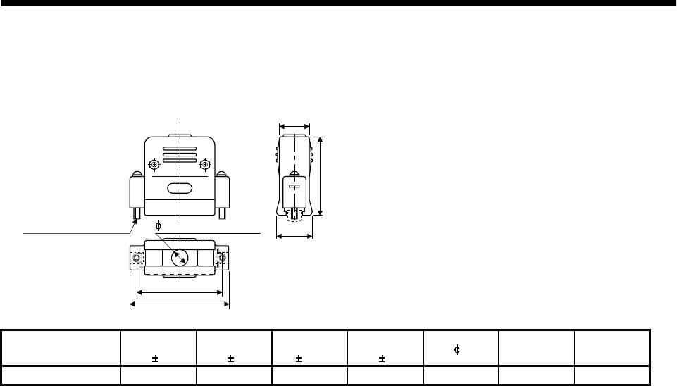
11 - 10
11. OUTLINE DIMENSION DRAWINGS
(3) Communication cable connector
<Japan Aviation Electronics Industry >
C
D
F
A
B
[Unit: mm]
([Unit: in])
Fitting fixing screw G E (max. diameter of
cable used)
Type A
1
B
1
C
0.25
D
1EF
Reference G
DE-C1-J6-S6 34.5(1.36) 19(0.75) 24.99(0.98) 33(1.30) 6(0.24) 18(0.71) #4-40
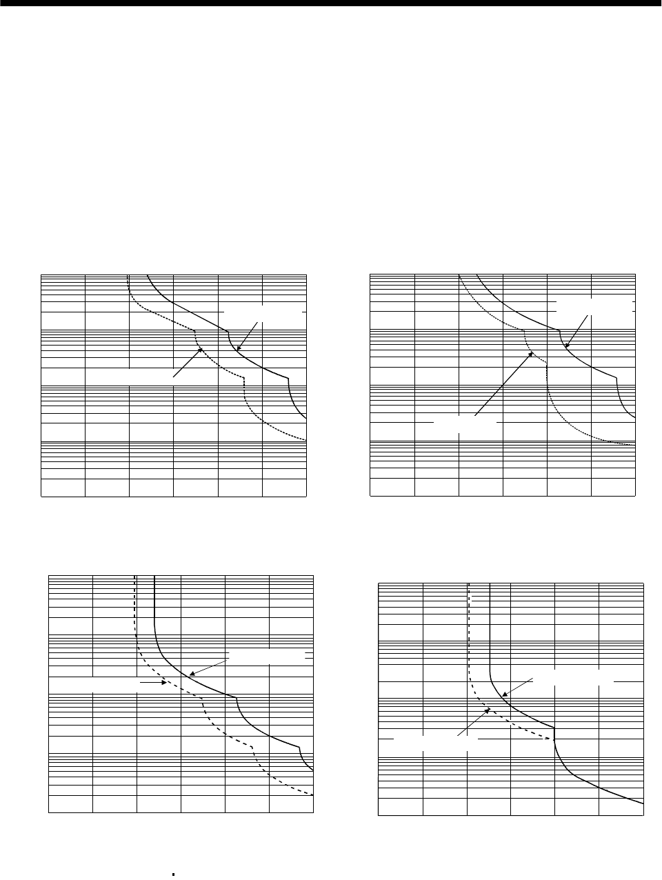
12 - 1
12. CHARACTERISTICS
12. CHARACTERISTICS
12.1 Overload protection characteristics
An electronic thermal relay is built in the servo amplifier to protect the servo motor and servo amplifier
from overloads. Overload 1 alarm (AL.50) occurs if overload operation performed is above the electronic
thermal relay protection curve shown in any of Figs 12.1. Overload 2 alarm (AL.51) occurs if the
maximum current flew continuously for several seconds due to machine collision, etc. Use the equipment
on the left-hand side area of the continuous or broken line in the graph.
In a machine like the one for vertical lift application where unbalanced torque will be produced, it is
recommended to use the machine so that the unbalanced torque is 70% or less of the rated torque.
1000
100
10
1
0.1
0 50 150 200 250 300
(Note) Load ratio [%]
Operation time[s]
During rotation
During stop
100
a. MR-J2S-10A to MR-J2S-100A
1000
100
10
1
0.1
0 50 100 150 200 250 300
(Note) Load ratio [%]
Operation time [s]
During rotation
During stop
b. MR-J2S-200A to MR-J2S-350A
0 50 100 150 200 250 300
1
10
100
1000
10000
(Note) Load ratio [%]
Operation time[s]
During rotation
During servo lock
c. MR-J2S-500A MR-J2S-700A
10000
1000
100
10
1
0 100 200 30
0
Operation time[s]
(Note) Load ratio [%]
During rotation
During servo lock
d. MR-J2S-11KA to MR-J2S-22KA
Note. If operation that generates torque more than 100% of the rating is performed with an abnormally high frequency in a servo motor
stop status (servo lock status) or in a 30r/min or less low-speed operation status, the servo amplifier may fail even when the
electronic thermal relay protection is not activated.
Fig 12.1 Electronic thermal relay protection characteristics

12 - 2
12. CHARACTERISTICS
12.2 Power supply equipment capacity and generated loss
(1) Amount of heat generated by the servo amplifier
Table 12.1 indicates servo amplifiers' power supply capacities and losses generated under rated load.
For thermal design of an enclosure, use the values in Table 12.1 in consideration for the worst
operating conditions. The actual amount of generated heat will be intermediate between values at
rated torque and servo off according to the duty used during operation. When the servo motor is run at
less than the maximum speed, the power supply capacity will be smaller than the value in the table,
but the servo amplifier's generated heat will not change.
Table 12.1 Power supply capacity and generated heat per servo amplifier at rated output
(Note 2)
Servo amplifier-generated heat[W] Area required for heat dissipation
Servo amplifier Servo motor
(Note 1)
Power supply
capacity[kVA] At rated torque With servo off [m2] [ft2]
HC-KFS053 13 0.3 25 15 0.5 5.4
HC-MFS053 13 0.3 25 15 0.5 5.4
MR-J2S-10A(1) HC-UFS13 0.3 25 15 0.5 5.4
HC-KFS23 0.5 25 15 0.5 5.4
HC-MFS23 0.5 25 15 0.5 5.4MR-J2S-20A(1) HC-UFS23 0.5 25 15 0.5 5.4
HC-KFS43 0.9 35 15 0.7 7.5
HC-MFS43 0.9 35 15 0.7 7.5MR-J2S-40A(1) HC-UFS43 0.9 35 15 0.7 7.5
HC-SFS52 1.0 40 15 0.8 8.6
HC-SFS53 1.0 40 15 0.8 8.6
MR-J2S-60A HC-LFS52 1.0 40 15 0.8 8.6
HC-KFS73 1.3 50 15 1.0 10.8
HC-MFS73 1.3 50 15 1.0 10.8MR-J2S-70A HC-UFS72 73 1.3 50 15 1.0 10.8
HC-SFS81 1.5 50 15 1.0 10.8
HC-SFS102 103 1.7 50 15 1.0 10.8MR-J2S-100A HC-LFS102 1.7 50 15 1.0 10.8
HC-SFS121 2.1 90 20 1.8 19.4
HC-SFS201 3.5 90 20 1.8 19.4
HC-SFS152 153 2.5 90 20 1.8 19.4
HC-SFS202 203 3.5 90 20 1.8 19.4
HC-RFS103 1.8 50 15 1.0 10.8
HC-RFS153 2.5 90 20 1.8 19.4
HC-UFS152 2.5 90 20 1.8 19.4
MR-J2S-200A
HC-LFS152 2.5 90 20 1.8 19.4
HC-SFS301 4.8 120 20 2.7 29.1
HC-SFS352 353 5.5 130 20 2.7 29.1
HC-RFS203 3.5 90 20 1.8 19.4
HC-UFS202 3.5 90 20 1.8 19.4
MR-J2S-350A
HC-LFS202 3.5 90 20 1.8 19.4
Note 1. Note that the power supply capacity will vary according to the power supply impedance. This value assumes that the power
factor improving reactor is not used.
2. Heat generated during regeneration is not included in the servo amplifier-generated heat. To calculate heat generated by the
regenerative brake option, use Equation 13.1 in Section 13.1.1.

12 - 3
12. CHARACTERISTICS
(Note 2)
Servo amplifier-generated heat[W] Area required for heat dissipation
Servo amplifier Servo motor
(Note 1)
Power supply
capacity[kVA] At rated torque With servo off [m2] [ft2]
HC-SFS502 7.5 195 25 3.9 42.0
HC-RFS353 5.5 135 25 2.7 29.1
HC-RFS503 7.5 195 25 3.9 42.0
HC-UFS352 5.5 195 25 3.9 42.0
HC-UFS502 7.5 195 25 3.9 42.0
HC-LFS302 4.5 120 25 2.4 25.8
MR-J2S-500A
HA-LFS502 7.5 195 25 3.9 42.0
HC-SFS702 10.0 300 25 6.0 64.6
MR-J2S-700A HA-LFS702 10.6 300 25 6.0 64.6
HA-LFS11K2 16.0 530 45 11 118.4
HA-LFS801 12.0 390 45 7.8 83.9
HA-LFS12K1 18.0 580 45 11.6 124.8
MR-J2S-11KA
HA-LFS11K1M 16.0 530 45 11.0 118.4
HA-LFS15K2 22.0 640 45 13 139.0
HA-LFS15K1 22.0 640 45 13 139.0MR-J2S-15KA HA-LFS15K1M 22.0 640 45 13 139.0
HA-LFS22K2 33.0 850 55 17 183.0
HA-LFS20K1 30.1 775 55 15.5 166.8
HA-LFS25K1 37.6 970 55 19.4 208.8
MR-J2S-22KA
HA-LFS22K1M 33.0 850 55 17.0 193.0
Note 1. Note that the power supply capacity will vary according to the power supply impedance. This value assumes that the power
factor improving reactor is not used.
2. Heat generated during regeneration is not included in the servo amplifier-generated heat. To calculate heat generated by the
regenerative brake option, use Equation 13.1 in Section 13.1.1.
12 - 4
12. CHARACTERISTICS
(2) Heat dissipation area for enclosed servo amplifier
The enclosed control box (hereafter called the control box) which will contain the servo amplifier
should be designed to ensure that its temperature rise is within 10 at the ambient temperature of
40 . (With a 5 (41 ) safety margin, the system should operate within a maximum 55 (131 )
limit.) The necessary enclosure heat dissipation area can be calculated by Equation 12.1:
P
AKT
.............................................................................................................................................(12.1)
where, A : Heat dissipation area [m2]
P : Loss generated in the control box [W]
T : Difference between internal and ambient temperatures [ ]
K : Heat dissipation coefficient [5 to 6]
When calculating the heat dissipation area with Equation 12.1, assume that P is the sum of all losses
generated in the enclosure. Refer to Table 12.1 for heat generated by the servo amplifier. "A" indicates
the effective area for heat dissipation, but if the enclosure is directly installed on an insulated wall,
that extra amount must be added to the enclosure's surface area.
The required heat dissipation area will vary wit the conditions in the enclosure. If convection in the
enclosure is poor and heat builds up, effective heat dissipation will not be possible. Therefore,
arrangement of the equipment in the enclosure and the use of a fan should be considered.
Table 12.1 lists the enclosure dissipation area for each servo amplifier when the servo amplifier is
operated at the ambient temperature of 40 (104 ) under rated load.
(Outside) (Inside)
Air flow
Fig. 12.5 Temperature distribution in enclosure
When air flows along the outer wall of the enclosure, effective heat exchange will be possible, because
the temperature slope inside and outside the enclosure will be steeper.
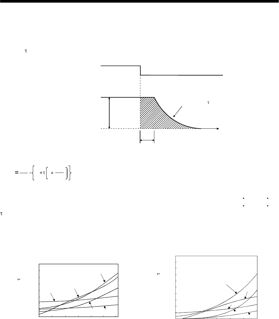
12 - 5
12. CHARACTERISTICS
12.3 Dynamic brake characteristics
Fig. 12.6 shows the pattern in which the servo motor comes to a stop when the dynamic brake is operated.
Use Equation 12.2 to calculate an approximate coasting distance to a stop. The dynamic brake time
constant varies with the servo motor and machine operation speeds. (Refer to Fig. 12.7. Please contact
us for the servo motor not indicated.)
V0Time constant
Emergency stop(EMG) OFF
ON
Machine speed
teTime
Fig. 12.6 Dynamic brake operation diagram
Lmax 60
V0JL
JM
te1.......................................................................................................................(12.2)
Lmax : Maximum coasting distance.................................................................................................[mm][in]
Vo : Machine rapid feedrate......................................................................................... [mm/min][in/min]
JM: Servo motor inertial moment.................................................................................[kg cm2][oz in2]
JL: Load inertia moment converted into equivalent value on servo motor shaft.....[kg cm2][oz in2]
: Brake time constant........................................................................................................................[s]
te: Delay time of control section...........................................................................................................[s]
For 7kW or less servo, there is internal relay delay time of about 30ms. For 11kW to 22kW
servo, there is delay time of about 100ms caused by a delay of the external relay and a delay of
the magnetic contactor built in the external dynamic brake.
Speed[r/min]
0
14
16
2
4
8
10
6
12
0 500 1000 1500 2000 2500 3000
13
73
23
43
053
Time constant [ms]
0
0.002
0.004
0.006
0.008
0.01
0.012
0.014
0.016
0.018
0.02
0 500 1000 1500 2000 2500 3000
73
23
43
053
13
Speed [r/min]
Time constant [s]
a. HC-KFS series b. HC-MFS series
Fig. 12.7 Dynamic brake time constant 1
12 - 6
12. CHARACTERISTICS
Time constant [s]
0.005
0.01
0.015
0.02
0.025
0.03
0.035
0.04
050 5000 1000
121
201
301
81
Speed [r/min]
Time constant [s]
Speed [r/min]
0
0.005
0.01
0.015
0.02
0.025
0.03
0.035
0.04
0.045
0 500 1000 1500 2000
352202
702
102 152
502
52
c. HC-SFS1000r/min series d. HC-SFS2000r/min series
0
0.02
0.04
0.06
0.08
0.1
0.12
50 500 1000 1500 2000 2500 30000
203
353
53
103
153
Speed [r/min]
Time constant [s]
Speed [r/min]
Time constant [s]
0
0.002
0.004
0.006
0.008
0.01
0.012
0.014
0.016
0.018
0 500 1000 1500 2000 2500 3000
153
503
103
353 203
e. HC-SFS3000r/min series f. HC-RFS series
Time constant [s]
Speed [r/min]
352
500 1000 1500 20000
0
0.01
0.02
0.03
0.04
0.05
0.06
0.07
0.08
0.09
0.1
502
72
202
152
0
0.01
0.02
0.03
0.04
0.05
0.06
50 500 100015002000250030000
43
23
0.07
13
73
Speed [r/min]
Time constant [s]
g. HC-UFS 2000r/min series h. HC-UFS3000r/min series
0500 1000 1500 20000
0.04
0.035
0.03
0.025
0.02
0.015
0.01
0.005
11K2
22K2
15K2
Time constant [s]
Speed [r/min]
0500 1000 1500 20000
40.0
35.0
30.0
25.0
20.0
15.0
10.0
5.0
302
Time constant [s]
Speed [r/min]
i. HA-LFS series j. HC-LFS series
Fig. 12.8 Dynamic brake time constant 2
12 - 7
12. CHARACTERISTICS
Use the dynamic brake at the load inertia moment indicated in the following table. If the load inertia
moment is higher than this value, the built-in dynamic brake may burn. If there is a possibility that the
load inertia moment may exceed the value, contact Mitsubishi.
Servo amplifier Load inertia moment ratio [times]
MR-J2S-10A to MR-J2S-200A
MR-J2S-10A1 to MR-J2S-40A1 30
MR-J2S-350A 16
MR-J2S-500A MR-J2S-700A 15
MR-J2S-11KA to MR-J2S-22KA (Note) 30
Note. The value assumes that the external dynamic brake is used.
12.4 Encoder cable flexing life
The flexing life of the cables is shown below. This graph calculated values. Since they are not guaranteed
values, provide a little allowance for these values.
1 107
5 107
1 108
5 106
1 106
5 105
1 105
5 104
1 104
5 103
1 103
a
b
Flexing life [times]
4 7 10 20 40 70 100 200
Flexing radius [mm]
a : Long flexing-life encoder cable
MR-JCCBL M-H
MR-JHSCBL M-H
MR-ENCBL M-H
b : Standard encoder cable
MR-JCCBL M-L
MR-JHSCBL M-L

12 - 8
12. CHARACTERISTICS
12.5 Inrush currents at power-on of main circuit and control circuit
The following table indicates the inrush currents (reference value) that will flow when the maximum
permissible voltage (253VAC) is applied at the power supply capacity of 2500kVA and the wiring length of
1m.
Inrush Currents (A0-p)
Servo Amplifier Main circuit power supply (L1, L2, L3) Control circuit power supply (L11, L21)
MR-J2S-10A 20A 30A (Attenuated to approx. 5A in 10ms)
MR-J2S-40A 60A 30A (Attenuated to approx. 5A in 10ms)
MR-J2S-70A 100A 54A (Attenuated to approx. 12A in 10ms)
70 to 100A
(Attenuated to approx. 0A in 0.5 to 1ms)
MR-J2S-200A 350A 120A (Attenuated to approx. 12A in 20ms) 100 to 130A
(Attenuated to approx. 0A in 0.5 to 1ms)
MR-J2S-500A 44A (Attenuated to approx. 20A in 20ms)
MR-J2S-700A 88A (Attenuated to approx. 20A in 20ms)
MR-J2S-11KA
MR-J2S-15KA
MR-J2S-22KA 235A (Attenuated to approx. 20A in 20ms)
30A
(Attenuated to approx. 0A in several ms)
MR-J2S-10A1 20A1 59A (Attenuated to approx. 5A in 4ms)
MR-J2S-40A1 72A (Attenuated to approx. 5A in 4ms) 100 to 130A
(Attenuated to approx. 0A in 0.5 to 1ms)
Since large inrush currents flow in the power supplies, always use no-fuse breakers and magnetic
contactors. (Refer to Section 13.2.2.)
When circuit protectors are used, it is recommended to use the inertia delay type that will not be tripped
by an inrush current.
13 - 1
13. OPTIONS AND AUXILIARY EQUIPMENT
13. OPTIONS AND AUXILIARY EQUIPMENT
WARNING
Before connecting any option or auxiliary equipment, make sure that the charge
lamp is off more than 15 minutes after power-off, then confirm the voltage with a
tester or the like. Otherwise, you may get an electric shock.
CAUTION Use the specified auxiliary equipment and options. Unspecified ones may lead to a
fault or fire.
13.1 Options
13.1.1 Regenerative brake options
CAUTION The specified combinations of regenerative brake options and servo amplifiers
may only be used. Otherwise, a fire may occur.
(1) Combination and regenerative power
The power values in the table are resistor-generated powers and not rated powers.
Regenerative power[W]
Servo amplifier Built-in regenerative
brake resistor MR-RB032
[40 ]MR-RB12
[40 ]MR-RB32
[40 ]MR-RB30
[13 ]
(Note)
MR-RB50
[13 ]
MR-RB31
[6.7 ]
(Note)
MR-RB51
[6.7 ]
MR-J2S-10A(1) 30
MR-J2S-20A(1) 10 30 100
MR-J2S-40A(1) 10 30 100
MR-J2S-60A 10 30 100
MR-J2S-70A 20 30 100 300
MR-J2S-100A 20 30 100 300
MR-J2S-200A 100 300 500
MR-J2S-350A 100 300 500
MR-J2S-500A 130 300 500
MR-J2S-700A 170 300 500
Note. Always install a cooling fan.
(Note) Regenerative power[W]
Servo amplifier External regenerative
brake resistor (Accessory) MR-RB65
[8 ]MR-RB66
[5 ]MR-RB67
[4 ]
MR-J2S-11KA 500 (800) 500 (800)
MR-J2S-15KA 850 (1300) 850 (1300)
MR-J2S-22KA 850 (1300) 850 (1300)
Note. Values in parentheses assume the installation of a cooling fan.
(2) Selection of the regenerative brake option
(a) Simple selection method
In horizontal motion applications, select the regenerative brake option as described below:
When the servo motor is run without load in the regenerative mode from the running speed to a
stop, the permissible duty is as indicated in Section 5.1 of the separately available Servo Motor
Instruction Manual.
For the servo motor with a load, the permissible duty changes according to the inertia moment of
the load and can be calculated by the following formula:
Permissible
duty Permissible duty for servo motor with no load (value indication Section 5.1 in Servo Motor Instruction Manual)
(m 1)
ratedspeed
running speed [times/min]
2
where m load inertia moment/servo motor inertia moment
From the permissible duty, find whether the regenerative brake option is required or not.
Permissible duty number of positioning times [times/min]
Select the regenerative brake option out of the combinations in (1) in this section.
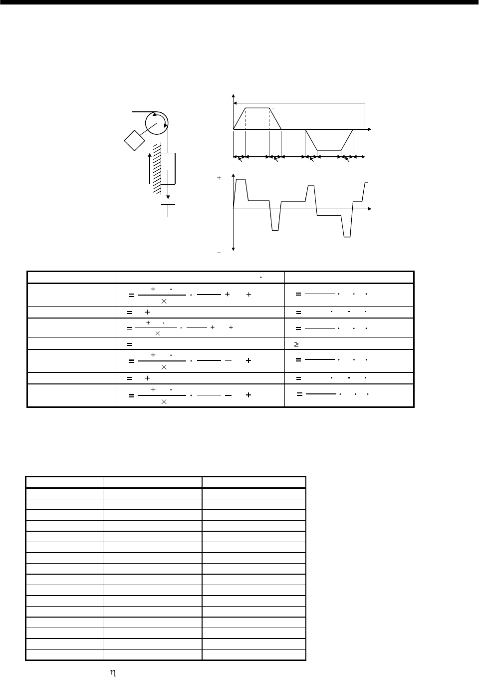
13 - 2
13. OPTIONS AND AUXILIARY EQUIPMENT
(b) To make selection according to regenerative energy
Use the following method when regeneration occurs continuously in vertical motion applications or
when it is desired to make an in-depth selection of the regenerative brake option:
a. Regenerative energy calculation
Use the following table to calculate the regenerative energy.
M
Friction
torque
Unbalance torque
TF
TU
Servo motor speed
Generated torque
Time
Up
No
tf(1 cycle)
Down
( )
( )
(Driving)
(Regenerative)
Tpsd2
t2 t3 t4t1
Tpsa2
Tpsd1
Tpsa1
1)
2)
3)
4) 5)
6)
7)
8)
Formulas for calculating torque and energy in operation
Regenerative power Torque applied to servo motor [N m] Energy [J]
1) T1(JL JM)
9.55 104
N01
Tpsa1 TUTFE12
0.1047 N0T1Tpsa1
2) T2 TU TFE2 0.1047 N0T2t1
3) T3(JL JM)
9.55 104
N01
Tpsd1 TUTFE32
0.1047 N0T3Tpsd1
4), 8) T4 TUE40 (No regeneration)
5) T5(JL JM)
9.55 104
N01
Tpsa2 TUTFE52
0.1047 N0T5Tpsa2
6) T6 TU TFE6 0.1047 N0T6t3
7) T7(JL JM)
9.55 104
N01
Tpsd2 TUTFE72
0.1047 N0T7Tpsd2
From the calculation results in 1) to 8), find the absolute value (Es) of the sum total of negative
energies.
b. Losses of servo motor and servo amplifier in regenerative mode
The following table lists the efficiencies and other data of the servo motor and servo amplifier in
the regenerative mode.
Servo amplifier Inverse efficiency[%] Capacitor charging[J]
MR-J2S-10A 55 9
MR-J2S-10A1 55 4
MR-J2S-20A 70 9
MR-J2S-20A1 70 4
MR-J2S-40A 85 11
MR-J2S-40A1 85 12
MR-J2S-60A 85 11
MR-J2S-70A 80 18
MR-J2S-100A 80 18
MR-J2S-200A 85 40
MR-J2S-350A 85 40
MR-J2S-500A 90 45
MR-J2S-700A 90 70
MR-J2S-11KA 90 120
MR-J2S-15KA 90 170
MR-J2S-22KA 90 250
Inverse efficiency ( ) :Efficiency including some efficiencies of the servo motor and servo
amplifier when rated (regenerative) torque is generated at rated speed.
Since the efficiency varies with the speed and generated torque, allow for
about 10%.
Capacitor charging (Ec) :Energy charged into the electrolytic capacitor in the servo amplifier.
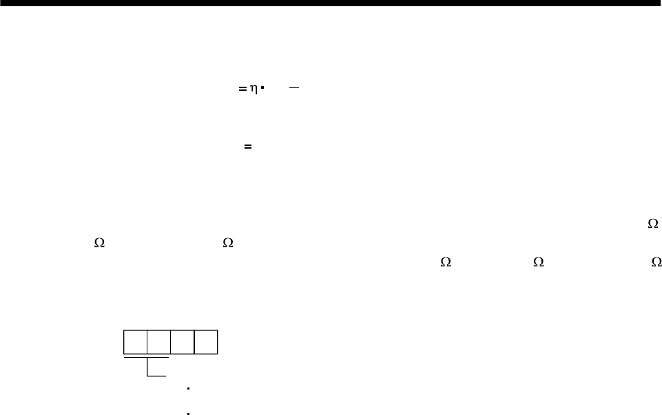
13 - 3
13. OPTIONS AND AUXILIARY EQUIPMENT
Subtract the capacitor charging from the result of multiplying the sum total of regenerative energies by
the inverse efficiency to calculate the energy consumed by the regenerative brake option.
ER [J] Es Ec
Calculate the power consumption of the regenerative brake option on the basis of single-cycle operation
period tf [s] to select the necessary regenerative brake option.
PR [W] ER/tf............................................................................................(13.1)
(3) Connection of the regenerative brake option
Set parameter No.2 according to the open to be used.
The MR-RB65, 66 and 67 are regenerative brake options that have encased the GRZG400-2 ,
GRZG400-1 and GRZG400-0.8 , respectively. When using any of these regenerative brake options,
make the same parameter setting as when using the GRZG400-2 , GRZG400-1 or GRZG400-0.8
(supplied regenerative brake resistors or regenerative brake option is used with 11kW or more servo
amplifier).
Parameter No.0
Selection of regenerative
00: Regenerative brake option or regenerative brake option is not used
with 7kW or less servo amplifier
Supplied regenerative brake resistors or regenerative brake option is
used with 11kW or more servo amplifier
02: MR-RB032
03: MR-RB12
04: MR-RB32
05: MR-RB30
06: MR-RB50
08: MR-RB31
09: MR-RB51
by fans to increase capability
0E: When regenerative brake resistors supplied to 11kW or more are cooled
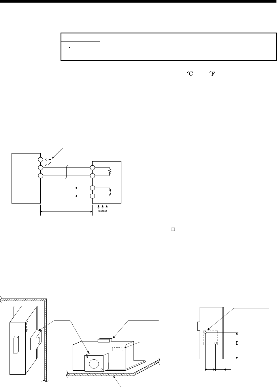
13 - 4
13. OPTIONS AND AUXILIARY EQUIPMENT
(4) Connection of the regenerative brake option
POINT
When using the MR-RB50 and MR-RB51, cooling by a fan is required.
Please obtain a cooling fan at your discretion.
The regenerative brake option will cause a temperature rise of +100 (+212 ) degrees relative to the
ambient temperature. Fully examine heat dissipation, installation position, used cables, etc. before
installing the option. For wiring, use flame-resistant cables and keep them clear of the regenerative
brake option body. Always use twisted cables of max. 5m(16.4ft) length for connection with the servo
amplifier.
(a) MR-J2S-350A or less
Always remove the wiring from across P-D and fit the regenerative brake option across P-C.
The G3 and G4 terminals act as a thermal sensor. G3-G4 are opened when the regenerative brake
option overheats abnormally.
Servo amplifier
Regenerative brake option
Note 1. When using the MR-RB50, forcibly cool it with a cooling fan (1.0m3/min, 92 or so).
2. Make up a sequence which will switch off the magnetic contactor (MC) when
abnormal heating occurs.
(Note2)
5m (16.4 ft) max.
D
PP
C
G3
G4
C
Always remove the lead from across P-D.
G3-G4 contact specifications
Maximum voltage: 120V AC/DC
Maximum current: 0.5A/4.8VDC
Maximum capacity: 2.4VA
Fan (Note 1)
For the MR-RB50 install the cooling fan as shown.
82.5 40 (1.58)
82.5
133
Fan installation screw hole dimensions
2-M3 screw hole
(for fan installation)
Depth 10 or less
(Screw hole already
machined)
Recommended fan:
Toyo Denki's TL396A or equivalent
Fan Terminal block
Thermal relay
Installation surface
Horizontal installation
Vertical
installation
Top
Bottom
(3.25)
(5.24)
(3.25)
[Unit : mm(in)]
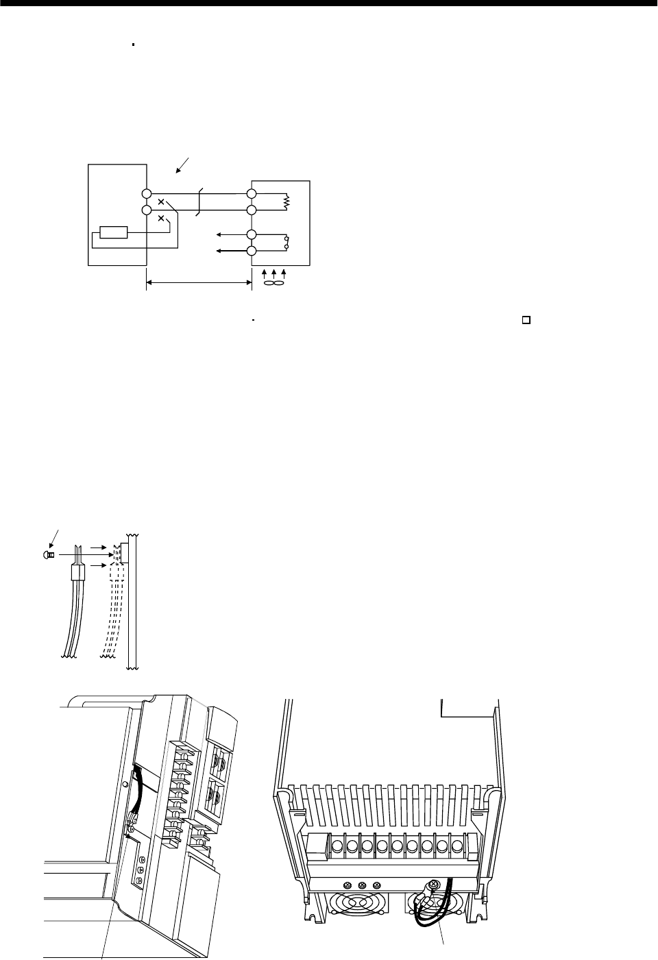
13 - 5
13. OPTIONS AND AUXILIARY EQUIPMENT
(b) MR-J2S-500A MR-J2S-700A
Always remove the wiring (across P-C) of the servo amplifier built-in regenerative brake resistor
and fit the regenerative brake option across P-C.
The G3 and G4 terminals act as a thermal sensor. G3-G4 are opened when the regenerative brake
option overheats abnormally.
PP
C
G3
(Note 2)
5m(16.4ft) or less
G4
C
Servo amplifier
Always remove wiring (across P-C) of servo
amplifier built-in regenerative brake resistor.
Regenerative brake option
Fan (Note 1)
Note 1. When using the MR-RB50 MR-RB51, forcibly cool it with a cooling fan (1.0m3/min, 92 or so).
2. Make up a sequence which will switch off the magnetic contactor (MC)
when abnormal heating occurs.
G3-G4 contact specifications
Maximum voltage: 120V AC/DC
Maximum current: 0.5A/4.8VDC
Maximum capacit
y
: 2.4VA
When using the regenerative brake resistor option, remove the servo amplifier's built-in
regenerative brake resistor terminals (across P-C), fit them back to back, and secure them to the
frame with the accessory screw as shown below.
Mounting method
Accessory screw
For MR-J2S-500A For MR-J2S-700A
Accessory screw
Accessory screw
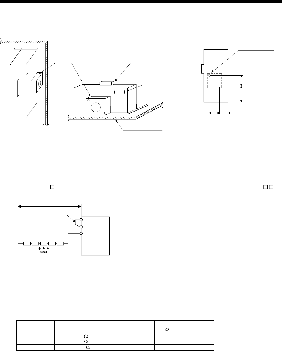
13 - 6
13. OPTIONS AND AUXILIARY EQUIPMENT
For the MR-RB50 MR-RB51 install the cooling fan as shown.
82.5 40 (1.58)
82.5
133
Fan installation screw hole dimensions
2-M3 screw hole
(for fan installation)
Depth 10 or less
(Screw hole already
machined)
Recommended fan:
Toyo Denki's TL396A or equivalent
Fan Terminal block
Thermal relay
Installation surface
Horizontal installation
Vertical
installation
Top
Bottom
(3.25)
(5.24)
(3.25)
[Unit : mm(in)]
(c) MR-J2S-11KA to MR-J2S-22KA (when using the supplied regenerative brake resistor)
When using the regenerative brake resistors supplied to the servo amplifier, the specified number
of resistors (4 or 5 resistors) must be connected in series. If they are connected in parallel or in less
than the specified number, the servo amplifier may become faulty and/or the regenerative brake
resistors burn. Install the resistors at intervals of about 70mm. Cooling the resistors with fans
(1.0m3/min, 92 (about two fans) improves the regeneration capability. In this case, set "0E " in
parameter No. 0.
P
C
Servo amplifier
(Note) Series connection
Fan
P1
Do not remove
the short bar.
5m or less
Note. The number of resistors connected in series depends on the resistor type. Install a thermal sensor or like to configure a
circuit that will shut off the main circuit power at abnormal overheat. The supplied regenerative brake resistor does not
have a built-in thermal sensor. If the regenerative brake circuit fails, abnormal overheat of the resistor is expected to
occur. On the customer side, please also install a thermal sensor for the resistor and provide a protective circuit that will
shut off the main circuit power supply at abnormal overheat. The detection level of the thermal sensor changes depending
on the resistor installation method. Please install the thermal sensor in the optimum position according to the customer's
design standards, or use our regenerative brake option having built-in thermal sensor (MR-RB65, 66, 67).
Regenerative Power [W]
Servo Amplifier Regenerative
Brake Resistor Normal Cooling Resistance
[]Number of
Resistors
MR-J2S-11KA GRZG400-2 500 800 8 4
MR-J2S-15KA GRZG400-1 850 1300 5 5
MR-J2S-22KA GRZG400-0.8 850 1300 4 5
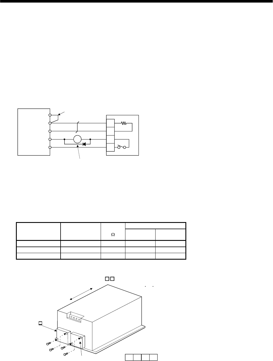
13 - 7
13. OPTIONS AND AUXILIARY EQUIPMENT
(d) MR-J2S-11KA-PX to MR-J2S-22KA-PX (when using the regenerative brake option)
The MR-J2S-11KA-PX to MR-J2S-22KA-PX servo amplifiers are not supplied with regenerative
brake resistors. When using any of these servo amplifiers, always use the MR-RB65, 66 or 67
regenerative brake option.
The MR-RB65, 66 and 67 are regenerative brake options that have encased the GRZG400-2Ω,
GRZG400-1Ω and GRZG400-0.8Ω, respectively. When using any of these regenerative brake
options, make the same parameter setting as when using the GRZG400-2Ω, GRZG400-1Ω or
GRZG400-0.8Ω (supplied regenerative brake resistors or regenerative brake option is used with
11kW or more servo amplifier).
Cooling the regenerative brake option with fans improves regenerative capability.
The G3 and G4 terminals are for the thermal sensor. G3-G4 are opened when the regenerative
brake option overheats abnormally.
RA
ALM
G3
G4
C
P
COM
C
P
P1
Servo amplifier Do not remove
the short bar.
Configure up a circuit which
shuts off main circuit power
when thermal sensor operates.
(Note)
Regenerative brake option
Note. Specifications of contact across G3-G4
Maximum voltage : 120V AC/DC
Maximum current : 0.5A/4.8VDC
Maximum capacity : 2.4VA
Regenerative Power [W]
Servo Amplifier
Regenerative
Brake Option
Model
Resistance
[]Without Fans With Fans
MR-J2S-11KA-PX MR-RB65 8 500 800
MR-J2S-15KA-PX MR-RB66 5 850 1300
MR-J2S-22KA-PX MR-RB67 4 850 1300
When using fans, install them using the mounting holes provided in the bottom of the regenerative
brake option. In this case, set "0E " in parameter No. 0.
Mounting screw
4-M3(0.118)
(1.0m3/min 92)
MR-RB65 66 67
Top
Bottom
TE1
G4 G3 C P
TE
2 cooling fans
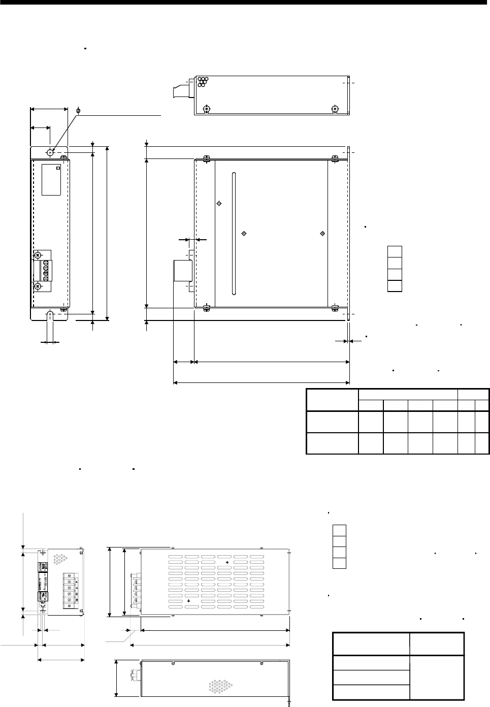
13 - 8
13. OPTIONS AND AUXILIARY EQUIPMENT
(5) Outline drawing
(a) MR-RB032 MR-RB12
LA
5 (0.20)
LB
TE1
6 (0.23)
6 (0.23) 156 (6.14)
168 (6.61)
144 (5.67)
12 (0.47)
6 (0.23)
12 (0.47)
20
(0.79) LD
1.6 (0.06)
LC
G3
G4
P
C
[Unit: mm (in)]
6 (0.24) mounting hole
MR-RB
TE1
Terminal block
G4
G3
C
P
Terminal screw: M3
Tightening torque:
3.2 [N m](28.32 [lb in])
Mounting screw
Screw size: M5
Tightening torque:
0.5 to 0.6 [N m](4 to 5 [lb in])
Variable dimensions Mass
Regenerative
brake option LA LB LC LD [kg] [lb]
MR-RB032 30
(1.18) 15
(0.59) 119
(4.69) 99
(3.9) 0.5 1.1
MR-RB12 40
(1.57) 15
(0.59) 169
(6.69) 149
(5.87) 1.1 2.4
(b) MR-RB30 MR-RB31 MR-RB32
Mounting screw
G4
G3
C
P
Terminal screw: M4
Tightening torque: 1.2 [N m] (10.6 [lb in])
100 (3.94)
90 (3.54)
10 (0.39)
7
8.5
(0.34)
8.5 (0.34)
125 (4.92)
150 (5.91)
142 (5.59)
17
(0.67)
318 (12.52)
335 (13.19)
79 (7.05)
G4 G3 C P
[Unit: mm (in)]
Terminal block
Tightening torque: 5.4 [N m](47.79 [lb in])
Regenerative
brake option
MR-RB30
MR-RB32
MR-RB31 2.9 (6.4)
Mass [kg] (lb)
Screw : M6
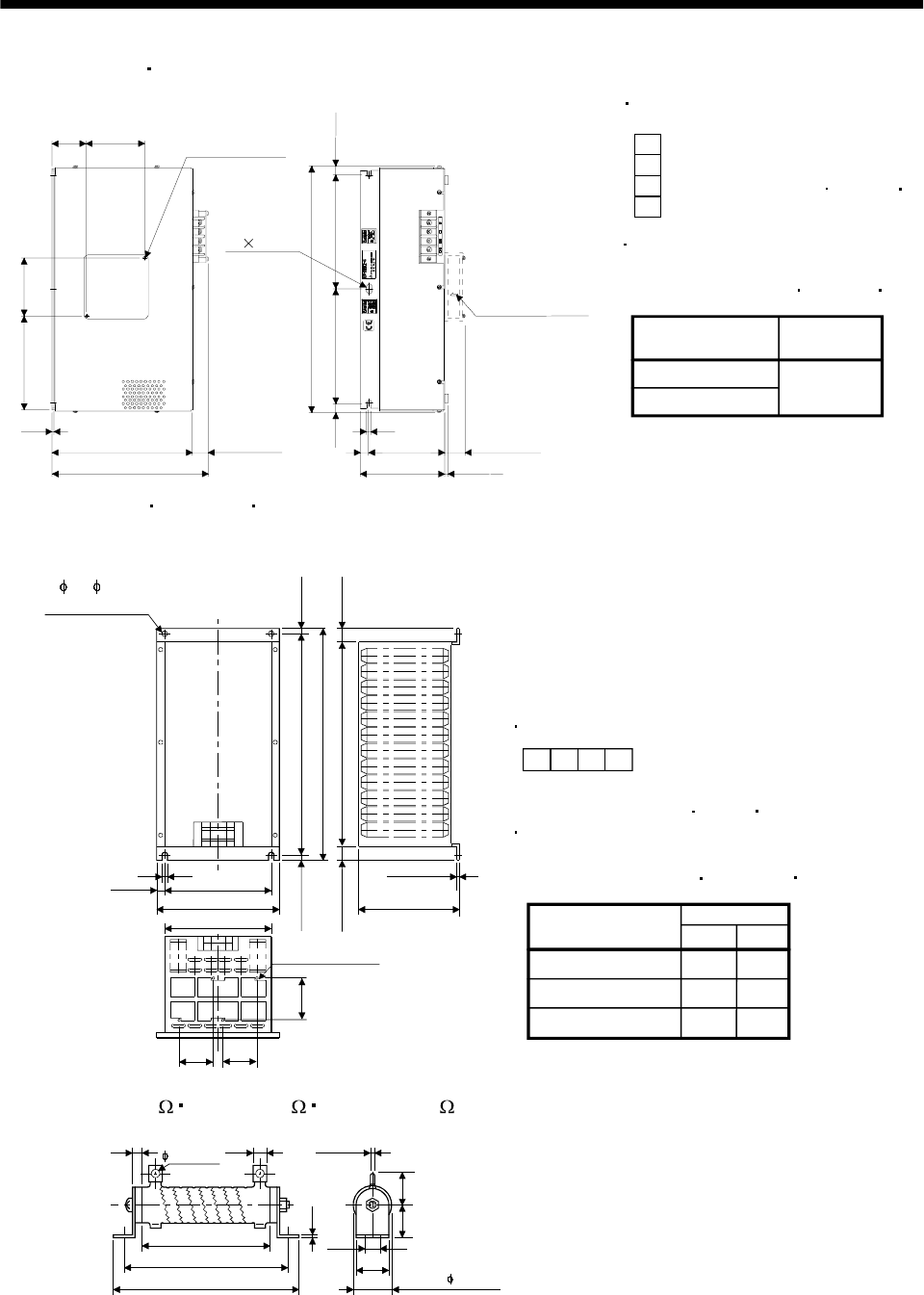
13 - 9
13. OPTIONS AND AUXILIARY EQUIPMENT
(c) MR-RB50 MR-RB51
Tightening torque: 5.4 [N m](47.79 [lb in])
Terminal block
G4
G3
C
P
Terminal screw: M4
Tightening torque: 1.2 [N m](10.6 [lb in])
[Unit: mm (in)]
Mounting screw
Regenerative
brake option
MR-RB50
MR-RB51 5.6 (12.3)
Mass [kg] (lb)
Screw : M6
49
(1.93) 82.5
(3.25)
200 (7.87)
223 (8.78)
2.3
(0.09) 108 (4.25)
120 (4.73)
12
(0.47)
7 (0.28)
Approx.30 (1.18)
8 (0.32)
12.5
(0.49)
350 (13.78)
162.5(6.39)
133
(5.24) 82.5
(3.25)
162.5 (6.39)
7 14 slot
Fan mounting screw
(2-M3 screw)
On opposite side
12.5
(0.49)
17 (0.67)
Wind blows in the
arrow direction.
G4 G3 C P
(d) MR-RB65 MR-RB66 MR-RB67
G4 G3 C P
Terminal block
Terminal screw: M5
Tightening torque: 2.0 [N m](17 [lb in])
Tightening torque: 13.2 [N m](116.83 [lb in])
Mounting screw
Screw size: M8
10 (0.39)
43 (1.69)
480 (18.9)
500 (19.69)
427 (16.81)
10 (0.39)
30 (1.18)
215 (8.47)
2.3 (0.09)
10 (0.39)
230 (9.06)
260 (10.24)
230 (9.06)
2- 10 ( 0.39)
monutinghde
TE1
G4G3 CP
[Unit: mm (in)]
15 (0.59)
82.5 82.5
82.5
4-M3 screw
Fan mounting
(3.24)
(
3.24
)
(3.24)
Regenerative
brake option
MR-RB65
MR-RB66
Mass
[kg] (lb)
MR-RB67
10
11
11
22.0
24.3
24.3
(e) GRZG400-2 GRZG400-1 GRZG400-0.8 (standard accessories)
385
411
9.5
40
40
10
Approx.
39(1.54)
Approx.330(13.0)
Approx. 47(1.85)
Approx.
5.5(0.22)
Approx.
10(0.39) Approx.
24(0.09) [Unit: mm (in)]
Tightening torque: 13.2 [N m](116.83 [lb in])
Mounting screw
Screw size: M8
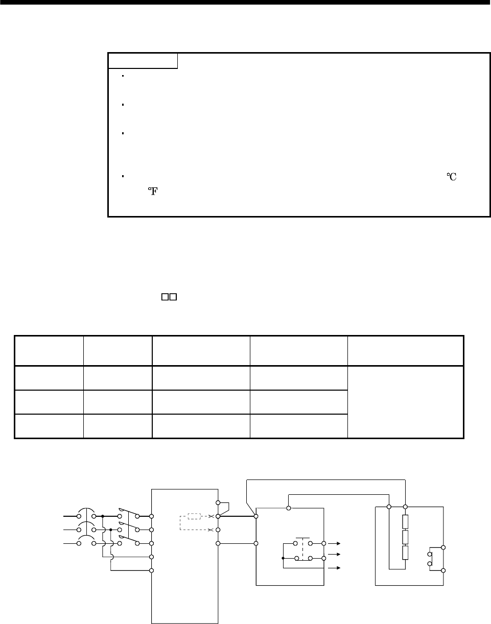
13 - 10
13. OPTIONS AND AUXILIARY EQUIPMENT
13.1.2 Brake unit
POINT
The brake unit and resistor unit of other than 200V class are not
applicable to the servo amplifier.
The brake unit and resistor unit of the same capacity must be combined.
The units of different capacities may result in damage.
The brake unit and resistor unit must be installed on a vertical surface in
the vertical direction. If they are installed in the horizontal direction or on
a horizontal surface, a heat dissipation effect reduces.
The temperature of the resistor unit casing rises to higher than 100
(212 ). Do not cause cables and combustibles to make contact with the
casing.
The brake unit is the integration of the regenerative control and resistor and is connected to the bus
(across P-N) of the servo amplifier. As compared to the MR-RB regenerative brake option, the brake unit
can return larger power. Hence, use the this brake unit when the MR-RB cannot provide sufficient
regenerative brake capability.
When using the brake unit, set "01 " in parameter No.0.
(1) Selection
Brake unit Resistor unit Permissible Continuous
Power [kw]
Max. Instantaneous
Power [kw] Applicable Servo Amplifier
FR-BU-15K FR-BR-15K 0.99 16.5
FR-BU-30K FR-BR-30K 1.99 33.4
FR-BU-55K FR-BR-55K 3.91 66.8
MR-J2S-500A
MR-J2S-700A
MR-J2S-11KA
MR-J2S-15KA
MR-J2S-22KA
(2) Connection example
MC
NFB
L1
L2
L3
L11
L21
C
N
PR
HA
HB
HC
PR P
TH1
TH2
THS
P
P1
Power supply
3-phase
200 to 300VAC
No-fuse breaker
Servo amplifer
(Note2)
FR-BU brake unit
Alarm
output
FR-BR resistor unit
(Note3)
(Note1) (Note1)
Note 1. Make up the external sequence to switch the power off when an alarm occurs or when the thermal relay is actuated.
2. When using servo amplifiers of 5kW and 7kW, always remove the lead of built-in regenerative brake resistor connected to P
terminal and C terminal.
3. When using servo ampliflers of 11kw to 22kw, always connect P-P1.
(
Factor
y
-wired.
)
When usin
g
the power factor improvin
g
DC reactor,
refer to Section 13.2.4
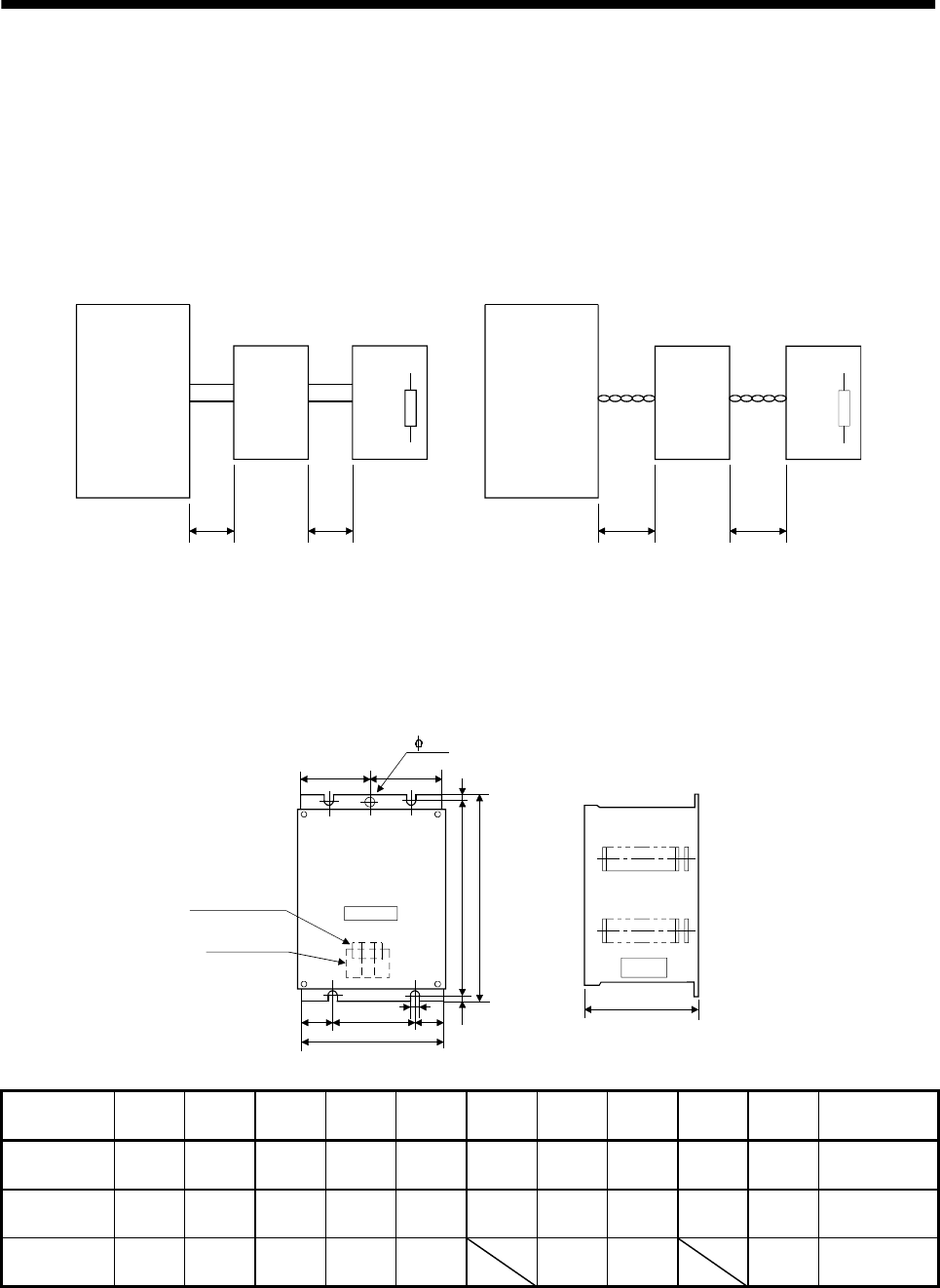
13 - 11
13. OPTIONS AND AUXILIARY EQUIPMENT
The cables between the servo amplifier and brake unit and between the resistor unit and brake unit
should be as short as possible. The cables longer than 5m(16.404ft) should be twisted. If twisted, the
cables must not be longer than 10m(32.808ft).
The cable size should be equal to or larger than the recommended size. See the brake unit instruction
manual. You cannot connect one set of brake unit to two servo amplifiers or two sets of brake units to
one servo amplifier.
P
NPR
P
NPP
PR P
PR
PR
PP
N
P
N
Servo amplifier Servo amplifier
Brake unit Resistor unit
5m (16.404ft)
or less
5m (16.404ft)
or less
10m (32.808ft)
or less
10m (32.808ft)
or less
Brake unit
Twist. Twist.
Resistor uni
t
(3) Outside dimensions
(a) Brake unit (FR-BU)
[Unit : mm(in)]
D
K
F
BA
B
EAA
A
C
E
EE
F
K
(Note)
Control circuit
terminals
Main circuit
terminals
Operation
display
Note. Ventilation ports are provided in both side faces and top face. The bottom face is open.
Brake Unit A AA B BA C D E EE K F Approx.
Mass [kg(Ib)]
FR-BU-15K 100
(3.937) 60
(2.362) 240
(9.446) 225
(10.039) 128
(5.039) 6
(0.236) 18.5
(0.728) 6
(0.236) 48.5
(1.909) 7.5
(0.295) 2.4
(5.291)
FR-BU-30K 160
(6.299) 90
(3.543) 240
(9.446) 225
(10.039) 128
(5.039) 6
(0.236) 33.5
(1.319) 6
(0.236) 78.5
(3.091) 7.5
(0.295) 3.2
(7.055)
FR-BU-55K 265
(10.433) 145
(5.709) 240
(9.446) 225
(10.039) 128
(5.039) 58.6
(2.307) 6
(0.236) 7.5
(0.295) 5.8
(12.787)
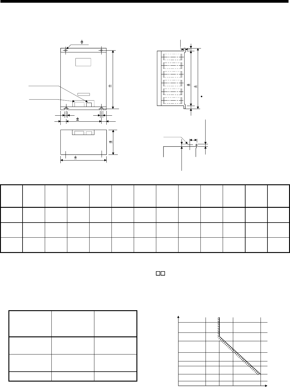
13 - 12
13. OPTIONS AND AUXILIARY EQUIPMENT
(b) Resistor unit (FR-BR) [Unit : mm(in)]
33 (1.299)
204
(8.031)
40 (1.575)
K
(F)
(F)
BA 1 (0.039)
C 5
(0.197)
2- D
AA 5 (0.197)
EE
(E)
A 5 (0.197)
EE
(E)
(Note)
Control circuit
terminals
Main circuit
terminals FR-BR-55K
Two eye bolts are provided
(as shown below).
Eye bolt
BB 3 (0.118)
B 5 (0.197)
Note. Ventilation ports are provided in both side faces and top face. The bottom face is open.
Resistor
Unit
Model
AAABBABBC D EEEK F
Approx.
Mass
[kg(Ib)]
FR-BR-
15K 170
(6.693) 100
(3.937) 450
(17.717) 432
(17.008) 410
(16.142) 220
(8.661) 6
(0.236) 35
(1.378) 6
(0.236) 1.6
(0.063) 20
(0.787) 15
(66.139)
FR-BR-
30K 340
(11.389) 270
(10.63) 600
(23.622) 582
(22.913) 560
(22.047) 220
(8.661) 10
(0.394) 35
(1.378) 10
(0.394) 2
(0.079) 20
(0.787) 30
(33.069)
FR-BR-
55K 480
(18.898) 410
(16.142) 700
(27.559) 670
(26.378) 620
(24.409) 450
(17.717) 12
(0.472) 35
(1.378) 12
(0.472) 3.2
(0.126) 40
(1.575) 70
(154.323)
13.1.3 Power regeneration converter
When using the power regeneration converter, set "01 " in parameter No.0.
(1) Selection
The converters can continuously return 75% of the nominal regenerative power. They are applied to
the servo amplifiers of the MR-J2S-500A to MR-J2S-22KA.
Power
regeneration
converter
Nominal
Regenerative
Power (kW)
Servo Amplifier
FR-RC-15 15 MR-J2S-500A
MR-J2S-700A
FR-RC-30 30 MR-J2S-11KA
MR-J2S-15KA
FR-RC-55K 55 MR-J2S-22KA
05075100150
500
300
200
100
50
30
20
Continuous energization time [sec]
Nominal regenerative power (%)
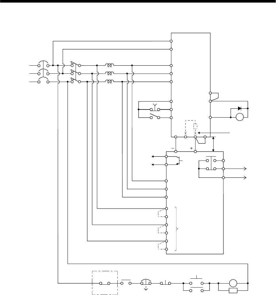
13 - 13
13. OPTIONS AND AUXILIARY EQUIPMENT
(2) Connection example
Power supply
3-phase
200V or 230VAC
NFB MC
Servo amplifier
L11
L21
L1
L2
L3
SK
ON
MC
BC
RDY
SE
Alarm
output
RDY
output
A
B
C
Operation ready
MC
OFF
EMG
RA2
FR-RC
Ready
(Note3)Power factor improving reactor
FR-BAL
R/L1
S/L2
T/L3
B
C
EMG
SON
SG COM
ALM
VDD
RA2
RRX
R
SX
S
TX
T
Phase detection
terminals
(Note 1)
Power regeneration
converter FR-RC
Note 1. When not using the phase detection terminals, fit the jumpers across RX-R, SX-S and TX-T. If the jumpers remain removed,
the FR-RC will not operate.
2. For the servo amplifiers of 5k and 7kW, always remove the wiring (across P-C) of the built-in regenerative brake resistor.
3. Refer to the power return converter FR-RC instruction manual (IB(NA)-66330) for the power factor improving reactor to be used.
When using FR-RC with the servo amplifier of 11k to 22kW, do not use the power factor improving reactor (FR-BEL) together.
4. For the amplifiers of 11k to 22kW, always connect across P-P1. (Wiring is factory-connected.)
NP 5m(16.4ft) or less
N/ P/
(Note2)
CP1
(Note4)
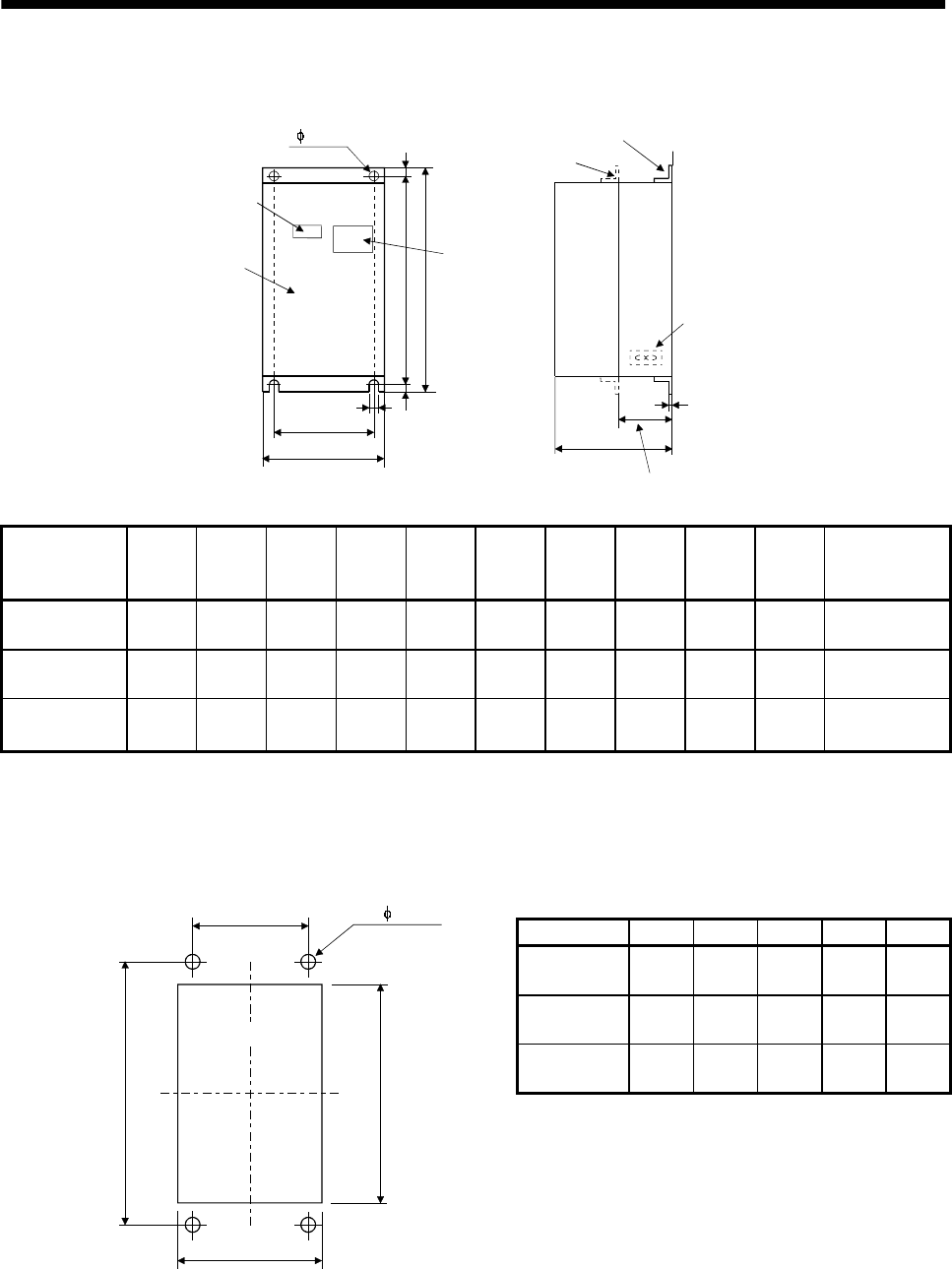
13 - 14
13. OPTIONS AND AUXILIARY EQUIPMENT
(3) Outside dimensions of the power regeneration converters [Unit : mm(in)]
AA
AC
FK
EE BA
BE
D
2- D hole
Rating plate
Front cover
Display
panel
window
Mounting foot (removable)
Mounting foot
movable
Cooling fan
Heat generation area outside mounting dimensio
n
Power
regeneration
converter
AAABBAC D EEEK F Approx.
Mass [kg(Ib)]
FR-RC-15K 270
(10.630) 200
(7.874) 450
(17.717) 432
(17.008) 195
(7.677) 10
(0.394) 10
(0.394) 8
(0.315) 3.2
(0.126) 87
(3.425) 19
(41.888)
FR-RC-30K 340
(13.386) 270
(10.630) 600
(23.622) 582
(22.913) 195
(7.677) 10
(0.394) 10
(0.394) 8
(0.315) 3.2
(0.126) 90
(3.543) 31
(68.343)
FR-RC-55K 480
(18.898) 410
(16.142) 700
(27.559) 670
(26.378) 250
(9.843) 12
(0.472) 15
(0.591) 15
(0.591) 3.2
(0.126) 135
(5.315) 55
(121.254)
(4) Mounting hole machining dimensions
When the power regeneration converter is fitted to a totally enclosed type box, mount the heat
generating area of the converter outside the box to provide heat generation measures. At this time, the
mounting hole having the following dimensions is machined in the box. [Unit : mm(in)]
Model A B D AA BA
FR-RC-15K 260
(10.236) 412
(16.220) 10
(0.394) 200
(7.874) 432
(17.009)
FR-RC-30K 330
(12.992) 562
(22.126) 10
(0.394) 270
(10.630) 582
(22.913)
FR-RC-55K 470
(18.504) 642
(25.276) 12
(0.472) 410
(16.142) 670
(26.378)
(AA)
(BA)
b
a
(2- D hole)
(Mounting hole)
13 - 15
13. OPTIONS AND AUXILIARY EQUIPMENT
13.1.4 External dynamic brake
(1) Selection of dynamic brake
The dynamic brake is designed to bring the servo motor to a sudden stop when a power failure occurs
or the protective circuit is activated, and is built in the 7kW or less servo amplifier. Since it is not built
in the 11kW or more servo amplifier, purchase it separately if required. Set " 1 " in the parameter
No. 1.
Servo amplifier Dynamic brake
MR-J2S-11KA DBU-11K
MR-J2S-15KA DBU-15K
MR-J2S-22KA DBU-22K
(2) Connection example
13 U14 V W
NFB MC
L11
L21
U
V
W
U
V
W
E
M
a
b
RA1
RA1
EMG
CN1B
5SON
CN1B
L3
L2
L1
RA1
15 EMG
10 SG
SDPlate
18 DB
13 COM
3VDD
MC SK
MC
ON
OFF
(Note1) EMG
Servo amplifier
Servo motor
Dynamic brake
Power supply
3-phase
200 to
230VAC
Operation-ready
Note1. Configure up the circuit so that power is switched off in the external sequence at servo alarm occurrence.
P
P1
(Note2)
2. When using servo ampliflers of 11kw to 22kw, always connect P-P1.(Factory-wired.) When using the power factor
improving DC reactor, refer to Section 13.2.4
13 - 16
13. OPTIONS AND AUXILIARY EQUIPMENT
Servo motor rotation
Coasting
Alarm
RA1
ON
OFF
emergency stop
(EMG)
Absent
Invalid
Valid
Short
Open
a. Timing chart at alarm occurrence b. Timing chart at emergency stop (EMG) validity
Dynamic brake
Base
ON
OFF
Coasting
Dynamic brake
Dynamic brake
Present
13 - 17
13. OPTIONS AND AUXILIARY EQUIPMENT
(3) Outline dimension drawing
UVW
D100(3.94) D
(0.2)5
C
E
G
F
2.3(0.09)
Terminal block
Screw : M3.5 Screw : M4
B
A
5
(0.2)
E
13 14
E
(GND) ab
[Unit: mm]
([Unit: in])
Tightening torque : 0.8 [N m](7 [lb in])] Tightening torque : 1.2 [N m](10.6 [lb in])]
Dynamic brake A B C D E F G Mass
[kg]([Ib])
Connection
wire [mm2]
DBU-11K 200
(7.87) 190
(7.48) 140
(5.51) 20
(0.79) 5
(0.2) 170
(6.69) 163.5
(6.44) 2 (4.41) 5.5
DBU -15K, 22K 250
(9.84) 238
(9.37) 150
(5.91) 25
(0.98) 6
(0.24) 235
(9.25) 228
(8.98) 6 (13.23) 5.5
POINT
Configure up a sequence which switches off the contact of the brake unit
after (or as soon as) it has turned off the servo on signal at a power failure
or failure.
For the braking time taken when the dynamic brake is operated, refer to
Section 12.3.
The brake unit is rated for a short duration. Do not use it for high duty.
When the dynamic brake is used, the power supply voltage is restricted as
indicated below.
3-Phase 170 to 220VAC/50Hz
3-Phase 170 to 242VAC/60Hz
13 - 18
13. OPTIONS AND AUXILIARY EQUIPMENT
13.1.5 Cables and connectors
(1) Cable make-up
The following cables are used for connection with the servo motor and other models. Those indicated
by broken lines in the figure are not options.
HC-SFS
HC-RFS
HC-UFS 2000r/min
HC-KFS
HC-MFS
HC-UFS 3000r/min
HA-LFS
CN1A CN1B
CN2 CN3
CON2 CN4
Operation
panel
Controller
Servo amplifier
Personal
computer
14)
13)
12)
To U, V, W,
19) 20)
1) 2)
6)
15) 16) 17) 18)
3) 4) 5)
7) 8)
7) 8)
3) 4) 5)
10)
10)
11)
11)
9)
(Note1)
(Note2)22)
Note 1. Use 12) and 13) with 7kW or less.
2. Use 21
)
with 11kW or more.
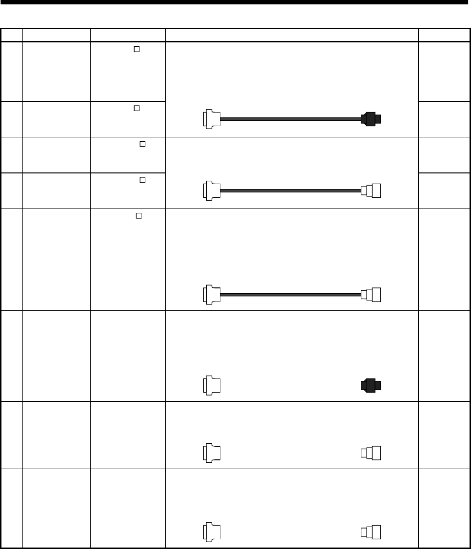
13 - 19
13. OPTIONS AND AUXILIARY EQUIPMENT
No. Product Model Description Application
1) Standard encoder
cable MR-JCCBL M-L
Refer to (2) in this
section.
Connector: 10120-3000VE
Shell kit: 10320-52F0-008
(3M or equivalent)
Housing : 1-172161-9
Connector pin : 170359-1
(Tyco Electronics or equivalent)
Cable clamp : MTI-0002
(Toa Electric Industry)
Standard
flexing life
IP20
2) Long flexing life
encoder cable MR-JCCBL M-H
Refer to (2) in this
section.
Long flexing
life
IP20
3) Standard encoder
cable MR-JHSCBL M-L
Refer to (2) in this
section.
Connector: 10120-3000VE
Shell kit: 10320-52F0-008
(3M or equivalent)
Connector: MS3106B20-29S
Cable clamp: MS3057-12A
(DDK)
Standard
flexing life
IP20
4) Long flexing life
encoder cable MR-JHSCBL M-H
Refer to (2) in this
section.
Long flexing
life
Connector: 10120-3000VE
Shell kit: 10320-52F0-008
(3M or equivalent)
Connector
: MS3106A20-29S (D190)
Cable clamp
: CE3057-12A-3 (D265)
Back shell: CE02-20BS-S
(DDK)
5) IP65-compliant
encoder cable MR-ENCBL M-H
Refer to (2) in this
section.
Long flexing
life
IP65
IP67
Not oil-
resistant.
Connector: 10120-3000VE
Shell kit: 10320-52F0-008
(3M or equivalent)
Housing : 1-172161-9
Connector pin: 170359-1
(Tyco Electronics or equivalent)
Cable clamp : MTI-0002
(Toa Electric Industry)
6) Encoder
connector set MR-J2CNM IP20
Connector: 10120-3000VE
Shell kit: 10320-52F0-008
(3M or equivalent)
Connector: MS3106B20-29S
Cable clamp: MS3057-12A
(DDK)
7) Encoder
connector set MR-J2CNS IP20
Connector: 10120-3000VE
Shell kit: 10320-52F0-008
(3M or equivalent)
Connector: MS3106A20-29S (D190)
Cable clamp: CE3057-12A-3 (D265)
Back shell: CE02-20BS-S
(DDK)
8) Encoder
connector set MR-ENCNS IP65
IP67
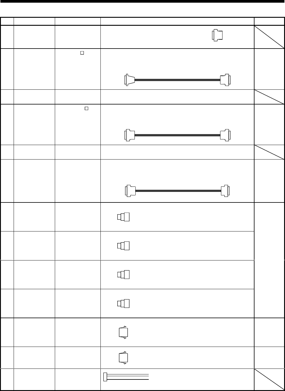
13 - 20
13. OPTIONS AND AUXILIARY EQUIPMENT
No. Product Model Description Application
9) Control signal
connector set MR-J2CN1 Connector: 10120-3000VE
Shell kit: 10320-52F0-008
(3M or equivalent) Qty: 2 each
Connector: HIF3BA-20D-2.54R
(Hirose Electric) Connector: 10120-6000EL
Shell kit: 10320-3210-000
(3M or equivalent)
10)
Junction
terminal block
cable
MR-J2TBL M
Refer to
Section13.1.6.
For junction
terminal
block
connection
11) Junction
terminal block MR-TB20 Refer to Section 13.1.6.
Connector: 10120-6000EL
Shell kit: 10320-3210-000
(3M or equivalent)
Connector: 10120-6000EL
Shell kit: 10320-3210-000
(3M or equivalent)
12)
Bus cable MR-J2HBUS M
Refer to
section13.1.7.
For
maintenance
junction
card
connection
13) Maintenance
junction card MR-J2CN3TM Refer to Section 13.1.7.
Connector: 10120-6000EL
Shell kit: 10320-3210-000
(3M or equivalent)
Connector: DE-9SF-N
Case: DE-C1-J6-S6
(Japan Aviation Electronics)
14)
Communication
cable MR-CPCATCBL3M
Refer to (3) in this
section.
For
connection
with PC-AT-
compatible
personal
computer
15)
Power supply
connector set MR-PWCNS1
Refer to the Servo
Motor Instruction
Manual.
Connector: CE05-6A22-23SD-B-BSS
Cable clamp:CE3057-12A-2 (D265)
(DDK)
16)
Power supply
connector set MR-PWCNS2
Refer to the Servo
Motor Instruction
Manual.
Connector: CE05-6A24-10SD-B-BSS
Cable clamp: CE3057-16A-2 (D265)
(DDK)
17)
Power supply
connector set MR-PWCNS2
Refer to the Servo
Motor Instruction
Manual.
Plug: CE05-6A24-10SD-B-BSS
Cable clamp: CE3057-16A-2 (D265)
(DDK)
18)
Brake connector
set MR-BKCN
Refer to the Servo
Motor Instruction
Manual.
Plug: MS3106A10SL-4S (D190) (DDK)
Cable connector: YS010-5-8 (Daiwa Dengyo)
EN
Standard-
compliant
IP65 IP67
19)
Power supply
connector set MR-PWCNK1
Refer to the Servo
Motor Instruction
Manual.
Plug: 5559-04P-210
Terminal: 5558PBT3L (For AWG16)(6 pcs.)
(Molex)
IP20
20) Power supply
connector set MR-PWCNK2 Plug: 5559-06P-210
Terminal: 5558PBT3L (For AWG16)(8 pcs.)
(Molex)
For motor
with brake
IP20
21) Monitor cable MR-H3CBL1M Servo amplifier side connector
(Tyco Electronics)
Housing: 171822-4
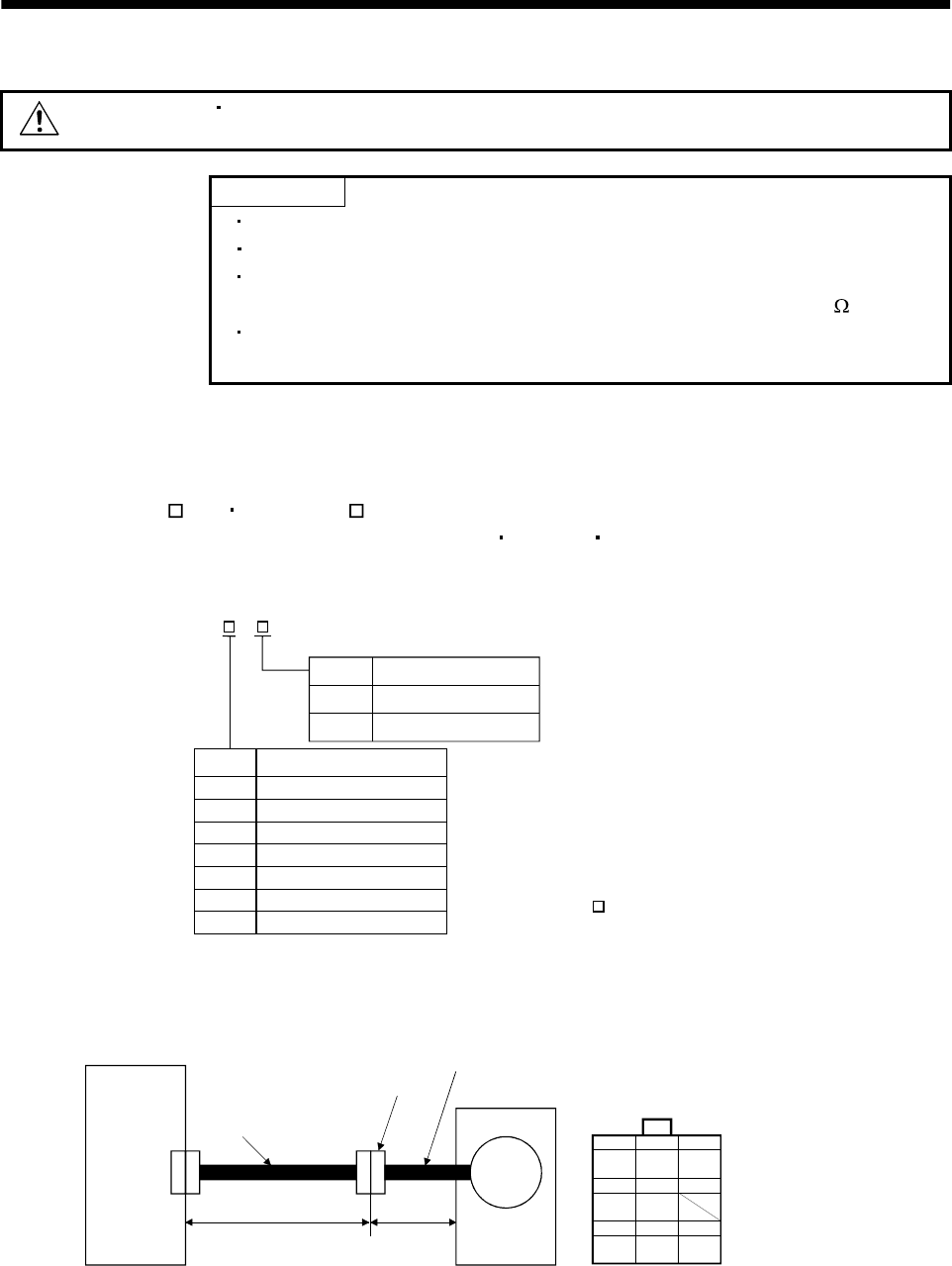
13 - 21
13. OPTIONS AND AUXILIARY EQUIPMENT
(2) Encoder cable
CAUTION If you have fabricated the encoder cable, connect it correctly.
Otherwise, misoperation or explosion may occur.
POINT
The encoder cable is not oil resistant.
Refer to Section 12.4 for the flexing life of the encoder cable.
When the encoder cable is used, the sum of the resistance values of the
cable used for P5 and the cable used for LG should be within 2.4 .
When soldering the wire to the connector pin, insulate and protect the
connection portion using heat-shrinkable tubing.
Generally use the encoder cable available as our options. If the required length is not found in the
options, fabricate the cable on the customer side.
(a) MR-JCCBL M-L MR-JCCBL M-H
These encoder cables are used with the HC-KFS HC-MFS HC-UFS3000r/min series servo
motors.
1) Model explanation
L
H
2
5
10
20
30
2 (6.56)
5 (16.4)
10 (32.8)
20 (65.6)
30 (98.4)
40
50 40 (131.2)
50 (164.0)
Symbol Specifications
Standard flexing life
Long flexing life
Symbol (Note) Cable length [m(ft)]
Note. MR-JCCBL M-H has
no 40(131.2) and 50m(164.0ft) sizes.
Model: MR-JCCBL M-
2) Connection diagram
For the pin assignment on the servo amplifier side, refer to Section 3.3.1.
123
456
789
MR MRR BAT
MD MDR
P5 LG SHD
Encoder connector
172161-9
(Tyco Electronics)
CN2
30cm
(0.98ft)
Servo amplifier
Encoder connector
Encoder cable
supplied to servo motor
Servo motor
Encoder
Encoder cable
(option or fabricated)
50m(164.0ft) max.
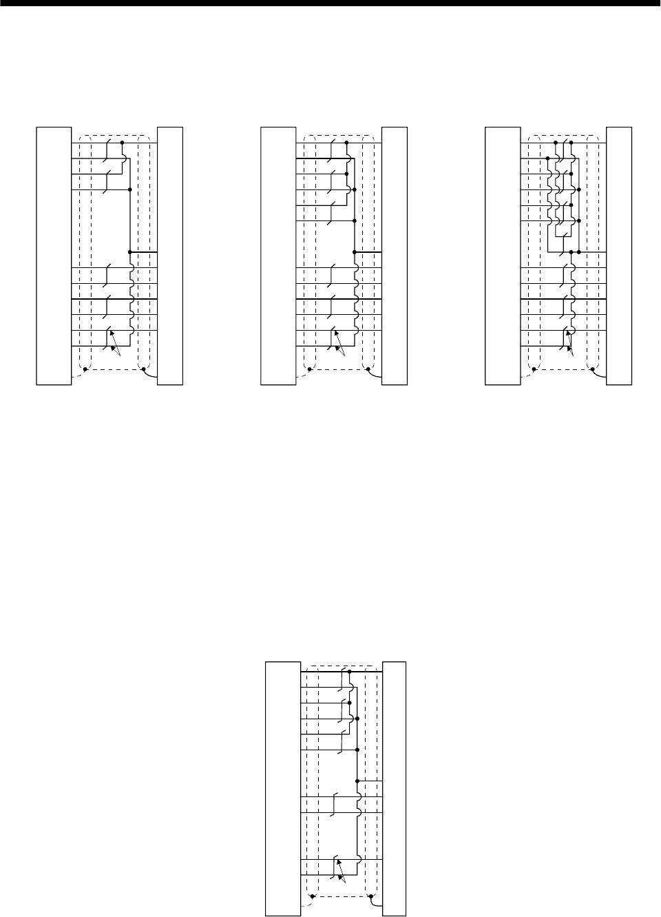
13 - 22
13. OPTIONS AND AUXILIARY EQUIPMENT
P5
LG
P5
LG
19
11
20
12
2
MR
MRR
7
17
MDR 16 5
3
7
4
18P5
LG
MD 6
LG 1
BAT 9
SD
1
2
8
9
P5
LG
P5
LG
19
11
20
12
2
MR
MRR
7
17
MDR 16 5
3
7
4
MR-JCCBL2M-L
MR-JCCBL5M-L
MR-JCCBL2M-H
MR-JCCBL5M-H
18
P5
LG
MD 6
LG 1
BAT 9
SD
1
2
8
9
P5
LG
P5
LG
19
11
20
12
2
MR
MRR
7
17
MDR 16 5
3
7
4
18P5
LG
MD 6
LG 1
BAT 9
SD
1
2
8
9
Drive unit side Encoder side
Plate
Drive unit side Encoder side
Plate
Drive unit side Encoder side
Plate
(Note) (Note) (Note)
Note. Always make connection for use in an absolute position detection system.
This wiring is not needed for use in an incremental system.
MR-JCCBL10M-L
to
MR-JCCBL30M-L
MR-JCCBL10M-H
to
MR-JCCBL50M-H
When fabricating an encoder cable, use the recommended wires given in Section 13.2.1 and the
MR-J2CNM connector set for encoder cable fabrication, and fabricate an encoder cable as shown
in the following wiring diagram. Referring to this wiring diagram, you can fabricate an encoder
cable of up to 50m(164.0ft) length including the length of the encoder cable supplied to the servo
motor.
When the encoder cable is to be fabricated by the customer, the wiring of MD and MDR is not
required.
Refer to Chapter 3 of the servo motor instruction manual and choose the encode side connector
according to the servo motor installation environment.
Note. Always make connection for use in an absolute position detection system.
This wiring is not needed for use in an incremental system.
19
11
20
12
18
2
P5
LG
P5
LG
P5
LG
7
17
9
1
MR
MRR
BAT
LG
SD
8
1
2
3
7
9
For use of AWG22
Drive unit side Encoder side
Plate
(Note)
(3M)
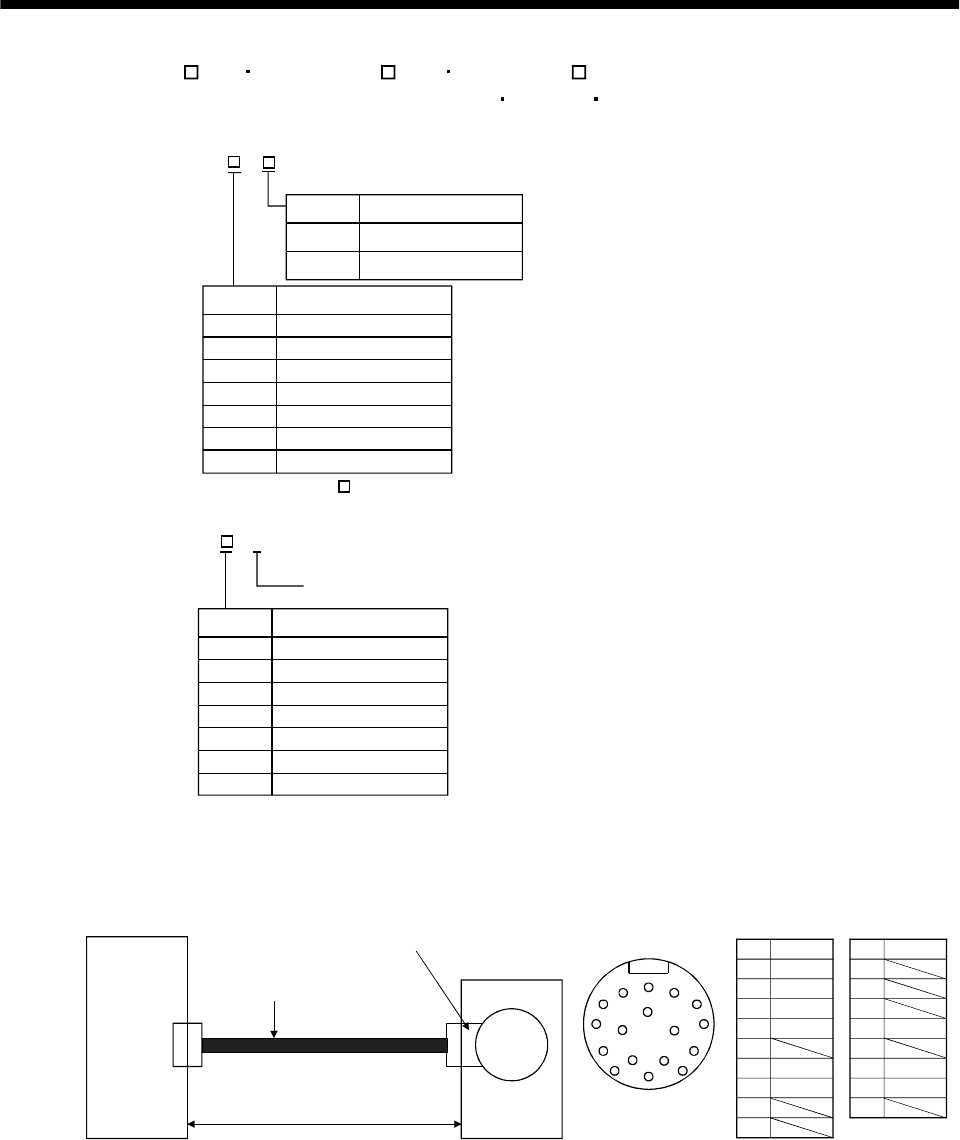
13 - 23
13. OPTIONS AND AUXILIARY EQUIPMENT
(b) MR-JHSCBL M-L MR-JHSCBL M-H MR-ENCBL M-H
These encoder cables are used with the HC-SFS HC-RFS HC-UFS2000r/min series servo motors.
1) Model explanation
L
H
2
5
10
20
30
2 (6.56)
5 (16.4)
10 (32.8)
20 (65.6)
30 (98.4)
Symbol Specifications
Standard flexing life
Long flexing life
Symbol Cable length [m(ft)]
Model: MR-JHSCBL M-
40
50 40 (131.2)
50 (164.0)
2
5
10
20
30
Long flexing life
Symbol Cable length [m(ft)]
Model: MR-ENCBL M-H
40
50
Note. MR-JHSCBL M-L has
no 40(131.2) and 50m(164.0ft) sizes.
2 (6.56)
5 (16.4)
10 (32.8)
20 (65.6)
30 (98.4)
40 (131.2)
50 (164.0)
2) Connection diagram
For the pin assignment on the servo amplifier side, refer to Section 3.3.1.
CN2
ABC
D
E
F
G
H
J
K
LMA
B
CMR
DMRR
E
FBAT
GLG
H
J
K
L
M
NSHD
P
RLG
SP5
T
Servo amplifier
50m(164.0ft) max.
Encoder connector
Servo motor
Encoder
Encoder connector Pin Signal
Encoder cable
(Optional or fabricated)
Pin Signal
R
S
TP
N
MD
MDR
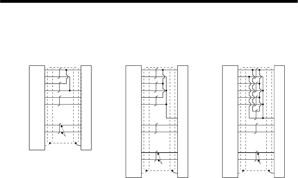
13 - 24
13. OPTIONS AND AUXILIARY EQUIPMENT
MR-JHSCBL2M-L
MR-JHSCBL5M-L
MR-JHSCBL2M-H
MR-JHSCBL5M-H
MR-ENCBL2M-H
MR-ENCBL5M-H
MR-JHSCBL10M-L
to
MR-JHSCBL30M-L
MR-JHSCBL10M-H
to
MR-JHSCBL50M-H
MR-ENCBL10M-H
to
MR-ENCBL50M-H
Servo amplifier side Encoder side
(Note2) Use of AWG24
(Less than 10m(32.8ft))
Servo amplifier side Encoder side Servo amplifier side Encoder side
Use of AWG22
(10m(32.8ft) to 50m(164.0ft))
Use of AWG24
(10m(32.8ft) to 50m(164.0ft))
(Note1)
(Note1) (Note1)
Plate Plate
P5
LG
P5
LG
MR
MRR
P5
LG
BAT
LG
SD
19
11
20
12
7
17
18
2
9
1
Plate
S
R
F
G
N
C
D
P5
LG
P5
LG
P5
LG
MR
MRR
BAT
LG
SD
19
11
20
12
18
2
7
17
9
1
S
R
C
D
F
N
G
P5
LG
P5
LG
P5
LG
MR
MRR
BAT
LG
SD
19
11
20
12
18
2
7
17
9
1
S
R
C
D
F
N
G
Note 1. This wiring is required for use in the absolute
position detection system. This wiring is not
needed for use in the incremental system.
2. AWG28 can be used for 5m(16.4ft) or less.
When fabricating an encoder cable, use the recommended wires given in Section 13.2.1 and the
MR-J2CNS connector set for encoder cable fabrication, and fabricate an encoder cable in
accordance with the optional encoder cable wiring diagram given in this section. You can
fabricate an encoder cable of up to 50m(164.0ft) length.
Refer to Chapter 3 of the servo motor instruction guide and choose the encode side connector
according to the servo motor installation environment.
13 - 25
13. OPTIONS AND AUXILIARY EQUIPMENT
(3) Communication cable
POINT
This cable may not be used with some personal computers. After fully
examining the signals of the RS-232C connector, refer to this section and
fabricate the cable.
(a) Model definition
Model : MR-CPCATCBL3M
Cable len
g
th 3[m]
(
10[ft]
)
(b) Connection diagram
Half-pitch 20 pins
D-SUB9 pins
3
2
5
7
8
6
4
TXD
RXD
GND
RTS
CTS
DSR
DTR
FG
RXD
LG
TXD
LG
Servo amplifier side
Plate
2
1
12
11
Personal computer side
MR-CPCATCBL3M
When fabricating the cable, refer to the connection diagram in this section.
The following must be observed in fabrication:
1) Always use a shielded, multi-core cable and connect the shield with FG securely.
2) The optional communication cable is 3m(10ft) long. When the cable is fabricated, its maximum
length is 15m(49ft) in offices of good environment with minimal noise.
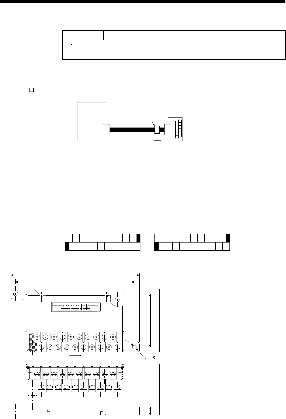
13 - 26
13. OPTIONS AND AUXILIARY EQUIPMENT
13.1.6 Junction terminal block (MR-TB20)
POINT
When using the junction terminal block, you cannot use SG of CN1A-20
and CN1B-20. Use SG of CN1A-10 and CN1B-10.
(1) How to use the junction terminal block
Always use the junction terminal block (MR-TB20) with the junction terminal block cable (MR-
J2TBL M) as a set. A connection example is shown below:
Servo amplifier
Junction terminal bloc
k
MR-TB20
CN1A
or
CN1B
Cable clamp
(AERSBAN-ESET)
Junction terminal
block cable
(MR-J2TBL05M)
Ground the junction terminal block cable on the junction terminal block side with the standard
accessory cable clamp fitting (AERSBAN-ESET). For the use of the cable clamp fitting, refer to Section
13.2.6, (2)(c).
(2) Terminal labels
Among the terminal block labels for the junction terminal block, use the two for the MR-J2S-A(MR-J2-
A). When changing the input signals in parameters No. 43 to 48, refer to (4) in this section and Section
3.3 and apply the accessory signal seals to the labels.
0
1
2
3
4
5
6
7
8
9
10
11
12
13
14
15
16
17
18
19
1) For CN1A
0
1
2
3
4
5
6
7
8
9
10
11
12
13
14
15
16
17
18
19
2) For CN1B
PP
LG OPC
COM PG
P15R
NP NG
SG
CR SD
INP DO1
VC TLC SG
PC TLA
VDD
LG SON TL P15R
RES LSP
COM EMG
ALM SD
LSN ZSP
LZ LB LZR LBR RD
OP LAR
LA
(3) Outline drawing
[Unit: mm]
([Unit: in.])
60(2.36)
750(1.97)
117(4.61)
126(4.96)
(0.28)
MITSUBISHI
MR-TB20
46.2(1.82)
Terminal screw: M3.5
Applicable cable: Max. 2mm
(Crimping terminal width: 7.2mm (0.283 in) max.
)
2
2- 4.5(0.18)
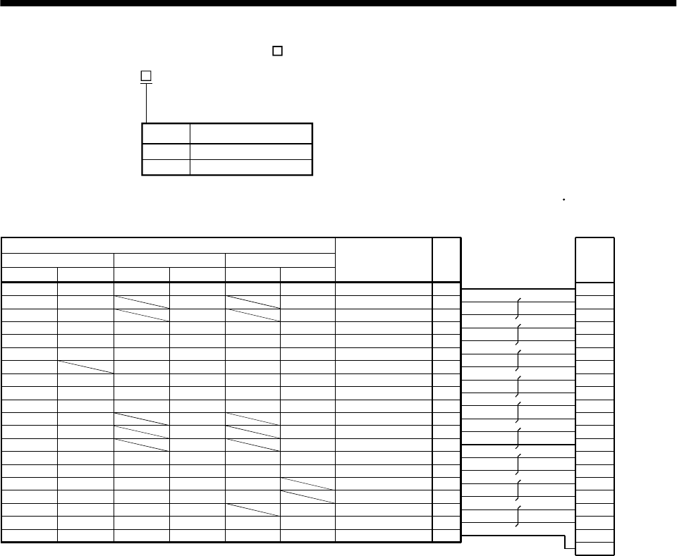
13 - 27
13. OPTIONS AND AUXILIARY EQUIPMENT
(4) Junction terminal block cable (MR-J2TBL M)
Model : MR-J2TBL M
Cable length[m(ft)]Symbol
05
1
0.5 (1.64)
1 (3.28)
Junction terminal block side connector (Hirose Electric)
HIF3BA-20D-2.54R (connector) Servo amplifier side (CN1A CN1B) connector (3M)
10 B1
0A1
11 B2
1A2
12 B3
2A3
13 B4
3A4
14 B5
4A5
15 B6
5A6
16 B7
6A7
17 B8
7A8
18 B9
8A9
19 B10
9A10
1
2
3
4
5
6
7
8
9
10
11
12
13
14
15
16
17
18
19
20
(Note) Symbol Junction terminal
block terminal No.
For CN1A For CN1B
Pin
No.
Pin
No.
Plate
LG
P15R
COM
SG
SD
SP1
LZ
LA
LB
OP
LZR
LAR
LBR
RD
LG
P15R
COM
SG
SA
SD
SP1
LZ
LA
LB
OP
LZR
LAR
LBR
RD
LG
VC
VDD
DO1
SON
TLC
PC
TLC
SG
P15R
TLA
COM
RES
EMG
LSP
LSN
ALM
ZSP
SD
LG
NP
PP
P15R
COM
SG
OPC
NG
PG
INP
SD
CR
LZ
LA
LB
OP
LZR
LAR
LBR
RD
LG
VC
VDD
DO1
SON
TLC
ST1
ST2
SG
P15R
TLA
COM
RES
EMG
LSP
LSN
ALM
ZSP
SD
SP2
LG
VLA
VDD
DO1
SON
VLC
RS2
RS1
SG
P15R
TC
COM
RES
EMG
ALM
ZSP
SD
SP2
For CN1A For CN1B For CN1A For CN1B
Position control mode Speed control mode Torque control mode
Note. The labels supplied to the junction terminal block are designed for the position control mode. When using the junction
terminal block in the speed or torque control mode, change the signal abbreviations using the accessory signal seals.
10120-6000EL (connector)
10320-3210-000 (shell kit)
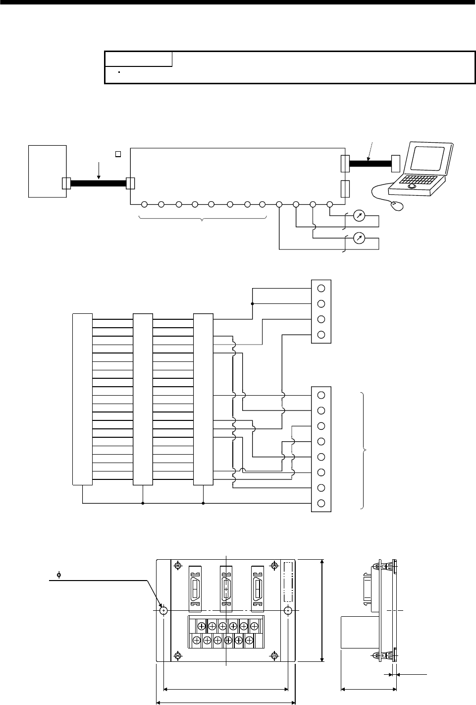
13 - 28
13. OPTIONS AND AUXILIARY EQUIPMENT
13.1.7 Maintenance junction card (MR-J2CN3TM)
POINT
Cannot be used with the MR-J2S-11KA to MR-J2S-22KA.
(1) Usage
The maintenance junction card (MR-J2CN3TM) is designed for use when a personal computer and
analog monitor outputs are used at the same time.
VDD
CN3B
CN3C
CN3ACN3
EM1 PESG
A1 A2 A3 A4 B4 B3 B2 B1 B5 B6 A5 A6
LG LG MO1 MO2
COM DI MBR EMGO
Communication cable
Maintenance junction card (MR-J2CN3TM)
Analog monitor 2
Analog monitor 1
Servo amplifier
Not used.
Bus cable
MR-J2HBUS M
(2) Connection diagram
LG
RXD
LG
MO3
SDP
LG
TXD
LG
MO2
P5
MO1
RDP
TRE
SDN
CN3A
1
2
3
4
5
6
7
8
9
10
11
13
12
14
15
16
17
18
19
20
1
2
3
4
5
6
7
8
9
10
11
13
12
14
15
16
17
18
19
20
1
2
3
4
5
6
7
8
9
10
11
13
12
14
15
16
17
18
19
20
CN3B CN3C
Shell Shell Shell
1
3
4
5
10
13
14
15
19
20
B5
B6
A5
A6
A1
A2
A3
A4
B4
B3
B2
B1
TE1
LG
LG
MO1
MO2
VDD
COM
EM1
DI
MBR
EMGO
SG
PE
Not used.
(3) Outline drawing
3(0.12)
41.5(1.63)
75(2.95)
88(3.47)
100(3.94)
MR-J2CN3TM
CN3A CN3B CN3C
A1
B1
A6
B6
TE1
[Unit: mm]
([Unit: in])
Mass: 110g(0.24Ib)
2- 5.3(0.21)(mounting hole)
13 - 29
13. OPTIONS AND AUXILIARY EQUIPMENT
(4) Bus cable (MR-J2HBUS M)
05
1
5
0.5 (1.64)
1 (3.28)
5 (16.4)
Symbol Cable length [m(ft)]
Model: MR-J2HBUS M
10120-6000EL (connector)
10320-3210-000 (shell kit)
MR-J2HBUS05M
MR-J2HBUS1M
MR-J2HBUS5M
1
11
2
12
3
13
4
14
5
15
6
16
7
17
8
18
9
19
10
20
1
11
2
12
3
13
4
14
5
15
6
16
7
17
8
18
9
19
10
20
10120-6000EL (connector)
10320-3210-000 (shell kit)
Plate
Plate
13.1.8 Battery (MR-BAT, A6BAT)
POINT
The revision (Edition 44) of the Dangerous Goods Rule of the
International Air Transport Association (IATA) went into effect on
January 1, 2003 and was enforced immediately. In this rule, "provisions of
the lithium and lithium ion batteries" were revised to tighten the
restrictions on the air transportation of batteries. However, since this
battery is non-dangerous goods (non-Class 9), air transportation of 24 or
less batteries is outside the range of the restrictions. Air transportation of
more than 24 batteries requires packing compliant with the Packing
Standard 903. When a self-certificate is necessary for battery safety tests,
contact our branch or representative. For more information, consult our
branch or representative. (As of Dec., 2005).
Use the battery to build an absolute position detection system.

13 - 30
13. OPTIONS AND AUXILIARY EQUIPMENT
13.1.9 MR Configurator (Servo configurations software)
The MR Configurator (servo configuration software MRZJW3-SETUP151E) uses the communication
function of the servo amplifier to perform parameter setting changes, graph display, test operation, etc.
on a personal computer.
(1) Specifications
Item Description
Communication signal Conforms to RS-232C.
Baudrate [bps] 57600, 38400, 19200, 9600
Monitor Display, high speed monitor, trend graph
Minimum resolution changes with the processing speed of the personal computer.
Alarm Display, history, amplifier data
Diagnostic Digital I/O, no motor rotation, total power-on time, amplifier version info, motor information,
tuning data, absolute encoder data, automatic voltage control, Axis name setting.
Parameters Parameter list, turning, change list, detailed information
Test operation Jog operation, positioning operation, motor-less operation, Do forced output, program operation.
Advanced function Machine analyzer, gain search, machine simulation.
File operation Data read, save, print
Others Automatic demo, help display
(2) System configuration
(a) Components
To use this software, the following components are required in addition to the servo amplifier and
servo motor:
Model (Note 1) Description
(Note 2)
Personal
computer
IBM PC-AT compatible where the English version of Windows® 95, Windows® 98, Windows® Me,
Windows NT® Workstation 4.0 or Windows® 2000 Professional operates
Processor: Pentium® 133MHz or more (Windows® 95, Windows® 98, Windows NT® Workstation 4.0,
Windows® 2000 Professional)
Pentium® 150MHz or more (Windows® Me)
Memory: 16MB or more (Windows® 95), 24MB or more (Windows® 98)
32MB or more (Windows® Me, Windows NT® Workstation 4.0, Windows® 2000 Professional)
Free hard disk space: 30MB or more
Serial port used
OS Windows® 95, Windows® 98, Windows® Me, Windows NT® Workstation 4.0, Windows® 2000 Professional
(English version)
Display One whose resolution is 800 600 or more and that can provide a high color (16 bit) display.
Connectable with the above personal computer.
Keyboard Connectable with the above personal computer.
Mouse Connectable with the above personal computer. Note that a serial mouse is not used.
Printer Connectable with the above personal computer.
Communication
cable MR-CPCATCBL3M
When this cannot be used, refer to (3) Section 12.1.5 and fabricate.
Note 1. Windows and Windows NT are the registered trademarks of Microsoft Corporation in the United State and other countries.
Pentium is the registered trademarks of Intel Corporation.
2. On some personal computers, this software may not run properly.
13 - 31
13. OPTIONS AND AUXILIARY EQUIPMENT
(b) Configuration diagram
1) When using RS-232C
CN3 CN2
Personal computer
To RS-232C
connector
Communication cable
Servo amplifier
Servo motor
2) When using RS-422
You can make multidrop connection of up to 32 axes.
Personal computer
CN3 CN2
Servo amplifier
Servo motor
Servo motor
Servo motor
Servo amplifier
Servo amplifier
(Axis 1)
(Axis 2)
(Axis 32)
RS-232C/RS-422
converter
To RS-232C
connector
(Note)
Communication cable
Note. For cable connection, refer to section 14.1.1.
CN3 CN2
CN3 CN2
13 - 32
13. OPTIONS AND AUXILIARY EQUIPMENT
13.1.10 Power regeneration common converter
POINT
For details of the power regeneration common converter FR-CV, refer to
the FR-CV Installation Guide (IB(NA)0600075).
Do not supply power to the main circuit power supply terminals (L1, L2,
L3) of the servo amplifier. Doing so will fail the servo amplifier and FR-CV.
Connect the DC power supply between the FR-CV and servo amplifier
with correct polarity. Connection with incorrect polarity will fail the FR-
CV and servo amplifier.
Two or more FR-CV's cannot be installed to improve regeneration
capability. Two or more FR-CV's cannot be connected to the same DC
power supply line.
When using the power regeneration common converter, set parameter No. 0 to "01 ".
(1) Selection
The power regeneration common converter FR-CV can be used with 750W to 22kW servo amplifiers.
There are the following restrictions on use of the FR-CV.
(a) Up to six servo amplifiers can be connected to one FR-CV.
(b) FR-CV capacity [W] Total of rated capacities [W] of servo amplifiers connected to FR-CV 2
(c) The total of used servo motor rated currents should be equal to or less than the applicable current
[A] of the FR-CV.
(d) Among the servo amplifiers connected to the FR-CV, the servo amplifier of the maximum capacity
should be equal to or less than the maximum connectable capacity [W].
The following table lists the restrictions.
FR-CV-
Item 7.5K 11K 15K 22K 30K 37K 55K
Maximum number of connected servo amplifiers 6
Total of connectable servo amplifier capacities [kW] 3.75 5.5 7.5 11 15 18.5 27.5
Total of connectable servo motor rated currents [A] 33 46 61 90 115 145 215
Maximum servo amplifier capacity [kW] 3.5 5 7 11 15 15 22
When using the FR-CV, always install the dedicated stand-alone reactor (FR-CVL).
Power regeneration common converter Dedicated stand-alone reactor
FR-CV-7.5K(-AT) FR-CVL-7.5K
FR-CV-11 K(-AT) FR-CVL-11 K
FR-CV-15K(-AT) FR-CVL-15K
FR-CV-22K(-AT) FR-CVL-22K
FR-CV-30K(-AT) FR-CVL-30K
FR-CV-37K FR-CVL-37K
FR-CV-55K FR-CVL-55K
13 - 33
13. OPTIONS AND AUXILIARY EQUIPMENT
(2) Connection diagram
RA2
EMG
SON
C
B
R/L11
Three-phase
200 to 230VAC
S/L21
T/L31
R2/L1
S2/L22
R2/L12
T2/L32
S2/L2
(Note 3)
SG
P24
SD
RDYB
RDYA
RSO
SE
A
T2/L3
R/L11
S/L21
T/MC1
RES
SD
(Note
1)
L11
RES
SG
SG
ALM
VIN
U
V
W
SG
(Note 1)
(Note1)
(Note 3)
RA1
EMG
SON
(Note 2)
RA3
RA2
RA1
RA4
24VDC
power
supply
U
V
WThermel
relay OHS2
OHS1
CN2
MC
NFB FR-CVL FR-CV
MC
RA2 RA3 RA4 EMG OFF ON
RESET
SK
MC
(Note 2)(Note 1)
Servo motor
Servo amplifier
(Note 1)
N
L21
P
P/L
P/L
P1
(Note 5)
(Note 4)
Note 1. Configure a sequence that will shut off main circuit power in the following cases:
Alarm occurred in the FR-CV or the servo amplifier.
Emergency stop is activated.
2. For the servo motor with thermal relay, configure a sequence that will shut off main circuit power when the thermal relay
operates.
3. For the servo amplifier, configure a sequence that will switch the servo on after the FR-CV is ready.
4. For 7kW or less servo amplifier, always remove the wiring (3.5kW or less: across P-D, 5k 7kW: across P-C) of built-in
regenerative brake resistor.
5. For the amplifiers of 11k to 22kW, make sure to connect across P-P1. (Wiring is factory-connected.)
(3) Wires used for wiring
(a) Wire sizes
1) Across P-P, N-N
The following table indicates the connection wire sizes of the DC power supply (P, N terminals)
between the FR-CV and servo amplifier. The used wires are based on the 600V vinyl wires.
Total of servo amplifier capacities [kW] Wires[mm2]
1 or less 2
23.5
55.5
78
11 14
15 22
22 50
13 - 34
13. OPTIONS AND AUXILIARY EQUIPMENT
2) Grounding
For grounding, use the wire of the size equal to or greater than that indicated in the following
table, and make it as short as possible.
Power regeneration common converter Grounding wire size [mm2]
FR-CV-7.5K TO FR-CV-15K 14
FR-CV-22K • FR-CV-30K 22
FR-CV-37K • FR-CV-55K 38
(b) Example of selecting the wire sizes
When connecting multiple servo amplifiers, always use junction terminals for wiring the servo
amplifier terminals P, N. Also, connect the servo amplifiers in the order of larger to smaller
capacities.
R2/L1
S2/L2
T2/L3
R/L11
S/L21
T/MC1
P/L
N/L
P
N
50mm2
Overall wiring length 5m or less
First unit:
50mm assuming that the total of servo amplifier
capacities is 27.5kW since 15kW + 7kW + 3.5kW
+ 2.0kW = 27.5kW.
P
N
P
N
P
N
22mm2
8mm2
3.5mm2
22mm2
8mm2
5.5mm2
3.5mm2
Junction terminals
Wire as short as possible.
Second unit:
22mm assuming that the total of servo amplifier
capacities is 15kW since 7kW + 3.5kW + 2.0kW =
12.5kW.
Third unit:
8mm assuming that the total of servo amplifier
capacities is 7kW since 3.5kW + 2.0kW = 5.5kW.
Fourth unit:
3.5mm assuming that the total of servo amplifier
capacities is 2kW since 2.0kW = 2.0kW.
FR-CV-55K Servo amplifier (15kW)
Servo amplifier (7kW)
Servo amplifier (3.5kW)
Servo amplifier (2kW)
2
2
2
2
(Note)
(Note)
(Note)
Note. For 7kW or less servo amplifier, always remove the wiring (3.5kW or less: across P-D, 5k 7kW: across P-C) of built-in
regenerative brake resistor.
(4) Other precautions
(a) Always use the FR-CVL as the power factor improving reactor. Do not use the FR-BAL or FR-BEL.
(b) The inputs/outputs (main circuits) of the FR-CV and servo amplifiers include high-frequency
components and may provide electromagnetic wave interference to communication equipment
(such as AM radios) used near them. In this case, interference can be reduced by installing the
radio noise filter (FR-BIF) or line noise filter (FR-BSF01, FR-BLF).
(c) The overall wiring length for connection of the DC power supply between the FR-CV and servo
amplifiers should be 5m or less, and the wiring must be twisted.
13 - 35
13. OPTIONS AND AUXILIARY EQUIPMENT
(5) Specifications
Power regeneration common converter
FR-CV-
Item
7.5K 11K 15K 22K 30K 37K 55K
Total of connectable servo amplifier capacities [kW] 3.75 5.5 7.5 11 15 18.5 27.5
Maximum servo amplifier capacity [kW] 3.5 5 7 11 15 15 22
Total of connectable servo motor rated
currents [A] 33 46 61 90 115 145 215
Short-time
rating Total capacity of applicable servo motors, 300% torque, 60s (Note1)
Output Regenerative
braking torque Continuous
rating 100% torque
Rated input AC voltage/frequency Three-phase 200 to 220V 50Hz, 200 to 230V 60Hz
Permissible AC voltage fluctuation Three-phase 170 to 242V 50Hz, 170 to 253V 60Hz
Permissible frequency fluctuation 5%
Power supply
Power supply capacity(Note2) [kVA] 17 20 28 41 52 66 100
Protective structure (JEM 1030), cooling system Open type (IP00), forced cooling
Ambient temperature -10 to +50 (non-freezing)
Ambient humidity 90%RH or less (non-condensing)Environment Ambience Indoors (without corrosive gas, flammable gas, oil mist, dust and dirt)
Altitude, vibration 1000m or less above sea level, 5.9m/s2 or less (compliant with JIS C 0040)
No-fuse breaker or leakage current breaker 30AF
30A 50AF
50A 100AF
75A 100AF
100A 225AF
125A 225AF
125A 225AF
175A
Magnetic contactor S-N20 S-N35 S-N50 S-N65 S-N95 S-N95 S-N125
Note1. This is the time when the protective function of the FR-CV is activated. The protective function of the servo amplifier is
activated in the time indicated in Section 12.1.
2. When connecting the capacity of connectable servo amplifier, specify the value of servo amplifier.
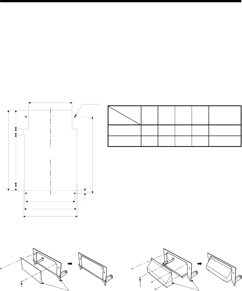
13 - 36
13. OPTIONS AND AUXILIARY EQUIPMENT
13.1.11 Heat sink outside mounting attachment (MR-JACN)
Use the heat sink outside mounting attachment to mount the heat generation area of the servo amplifier
in the outside of the control box to dissipate servo amplifier-generated heat to the outside of the box and
reduce the amount of heat generated in the box, thereby allowing a compact control box to be designed.
In the control box, machine a hole having the panel cut dimensions, fit the heat sink outside mounting
attachment to the servo amplifier with the fitting screws (4 screws supplied), and install the servo
amplifier to the control box.
The environment outside the control box when using the heat sink outside mounting attachment should
be within the range of the servo amplifier operating environment conditions.
(1) Panel cut dimensions
[Unit: mm(in)]
Changeable
dimension
Model
A B C D Servo amplifier
MR-JACN15K 236
(9.291) 255
(10.039) 270
(10.63) 203
(7.992) MR-J2S-11KA
MR-J2S-15KA
MR-JACN22K 326
(12.835) 345
(13.583) 360
(14.173) 290
(11.417) MR-J2S-22KA
A
B
C
125
(4.921)
331 (13.031)
39.5
(1.555)
535 (21.063)
510 (20.079)
18
(0.709)
D4-M10 Screw
Punched
hole
39.5
(1.555)
(2) How to assemble the attachment for a heat sink outside mounting attachment
Attachment
Screw
(4 places)
Attachment
Screw
(2 places)
MR-JACN15K MR-JACN22K
13 - 37
13. OPTIONS AND AUXILIARY EQUIPMENT
(3) Fitting method
Attachment
Fit using the
assembiling
screws. Servo
amplifier
Attachment
Servo
amplifier Punched
hole
Control box
a. Assembling the heat sink outside mounting attachment b. Installation to the control box
(4) Outline dimension drawing
(a) MR-JACN15K (MR-J2S-11KA, MR-J2S-15KA)
Servo amplifier
Attachment
Panel
Panel
20 (0.787)
145 (5.709)
400 (15.748)
35
(1.378)
194 (7.638)
84
(3.307)
58
(2.283)
12
(0.472)
3.2 (0.126)
236 (9.291)
155 (6.102) 11.5
(0.453)
260
(10.236)
280 (11.024)
260 (10.236)
510 (20.079)
580 (22.835)
Servo amplifier
4- 12
Mounting hole
Attachment
105
(4.134)
13 - 38
13. OPTIONS AND AUXILIARY EQUIPMENT
(b) MR-JACN22K (MR-J2S-22KA)
68(2.677)
145(5.709)400(15.748)
35(1.378)
194(7.638)84
58
12
3.2(0.126)
326(12.835)
155(6.102) 105 11.5
260
370(14.567)
350(13.78)
510(20.079)
580(22.835)
Attachment
Servo amplifer
Attachment
4- 12
Mounting hole
Servo amplifer
Panel
Panel
(2.283)
(0.472)
(3.307)
(10.236)
(4.134) (0.453)
13 - 39
13. OPTIONS AND AUXILIARY EQUIPMENT
13.2 Auxiliary equipment
Always use the devices indicated in this section or equivalent. To comply with the EN Standard or UL/C-
UL (CSA) Standard, use the products which conform to the corresponding standard.
13.2.1 Recommended wires
(1) Wires for power supply wiring
The following diagram shows the wires used for wiring. Use the wires given in this section or
equivalent.
C
P
U
V
W
L11
L21
B1
B2
U
V
W
L1
L2
L3Motor
Brake unit or
Return converter N
1) Main circuit power supply lead
Power supply Servo amplifier
3) Motor power supply lead
Servo motor
Electro-
magnetic
brake
Encoder
Encoder cable
(refer to Section 13.1.5)
4) Regenerative brake option lead
5) Electromagnetic
brake lead
2) Control power supply lead
Regenerative brake option
6) Brake unit lead or
Return converter
Cooling fan
BU
BV
BW
Fan lead
Power supply
The following table lists wire sizes. The wires used assume that they are 600V vinyl wires and the
wiring distance is 30m(98.4ft) max. If the wiring distance is over 30m(98.4ft), choose the wire size in
consideration of voltage drop.
The alphabets (a, b, c) in the table correspond to the crimping terminals (Table 13.2) used to wire the
servo amplifier. For connection with the terminal block TE2 of the MR-J2S-100A or less, refer to
Section 3.11.
The servo motor side connection method depends on the type and capacity of the servo motor. Refer to
Section 3.8.
To comply with the UL/C-UL (CSA) Standard, use UL-recognized copper wires rated at 60 (140 ) or
more for wiring.
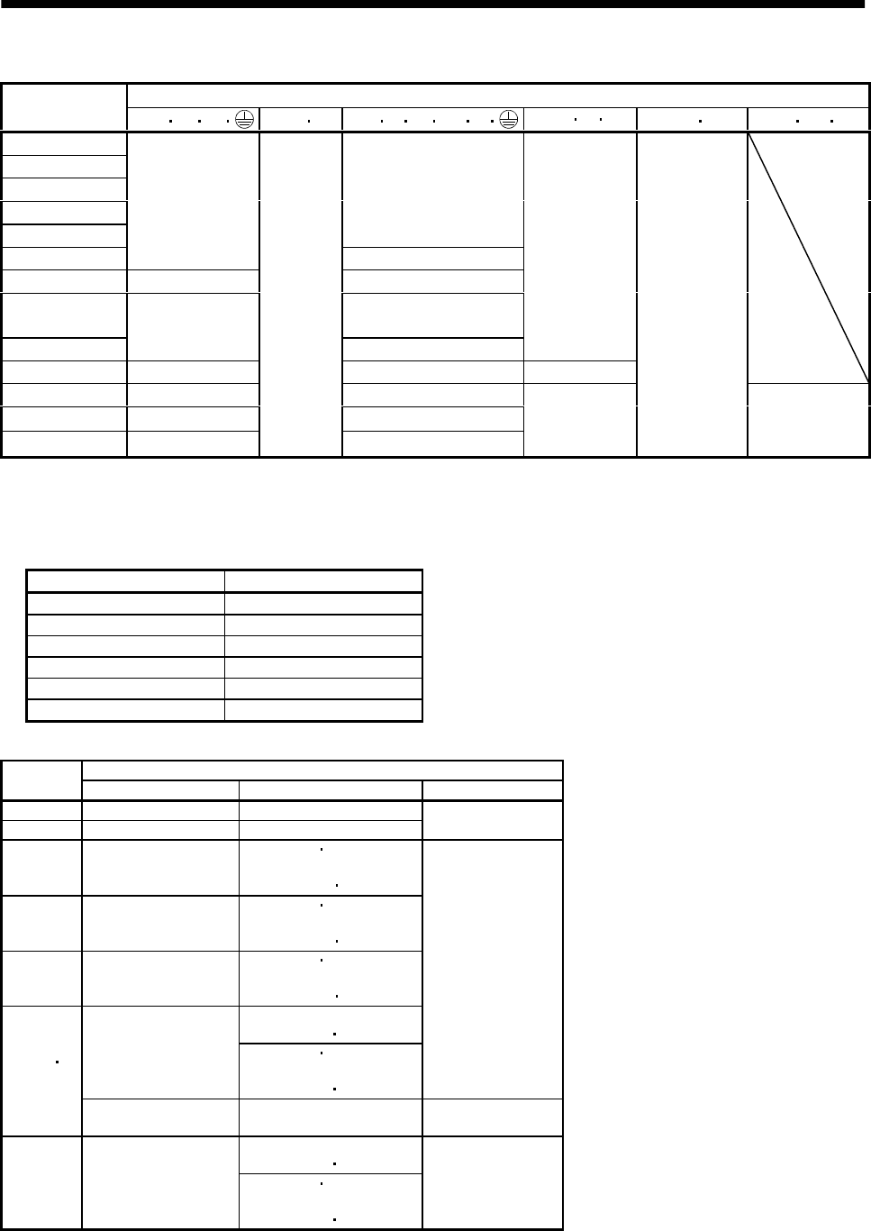
13 - 40
13. OPTIONS AND AUXILIARY EQUIPMENT
Table 13.1 Recommended wires
(Note 1) Wires [mm2]
Servo amplifier 1) L1L2L32) L11 L21 3) U V W P1P4) P CN5) B1B2 6) BU BV BW
MR-J2S-10A(1)
MR-J2S-20A(1)
MR-J2S-40A(1)
MR-J2S-60A
MR-J2S-70A
1.25 (AWG16) : a
MR-J2S-100A
2 (AWG14) : a
2 (AWG14) : a
MR-J2S-200A 3.5 (AWG12) : b 3.5 (AWG12) : b
MR-J2S-350A (Note 2)
5.5 (AWG10) : b
MR-J2S-500A 5.5 (AWG10) : b 5.5 (AWG10) : b
2 (AWG14) : a
MR-J2S-700A 8 (AWG8) : c 8 (AWG8) : c 3.5(AWG12) : b
MR-J2S-11KA 14 (AWG6) :d 22 (AWG4) :e
MR-J2S-15KA 22 (AWG4) :e 30 (AWG2) :f
MR-J2S-22KA 50 (AWG1/0) :g
1.25
(AWG16)
60 (AWG2/0) :g 5.5(AWG10) : b
1.25 (AWG16)
2(AWG14)
Note 1. For the crimping terminals and applicable tools, refer to table 13.2:
2. 3.5mm2 for use of the HC-RFS203 servo motor.
Use wires 6) of the following sizes with the brake unit (FR-BU) and power regeneration converter (FR-
RC).
Model Wires[mm2]
FR-BU-15K 3.5(AWG12)
FR-BU-30K 5.5(AWG10)
FR-BU-55K 14(AWG6)
FR-RC-15K 14(AWG6)
FR-RC-30K 14(AWG6)
FR-RC-55K 22(AWG4)
Table 13.2 Recommended crimping terminals
Servo amplifier side crimping terminals
Symbol Crimping terminal Applicable tool Maker name
a 32959 47387
b 32968 59239 Tyco Electronics
cFVD8-5
Body YF-1 E-4
Head YNE-38
Dice DH-111 DH-121
d FVD14-6 Body YF-1 E-4
Head YNE-38
Dice DH-112 DH-122
e FVD22-6 Body YF-1 E-4
Head YNE-38
Dice DH-113 DH-123
Body YPT-60-21
Dice TD-124 TD-112
38-S6 Body YF-1 E-4
Head YET-60-1
Dice TD-124 TD-112
Japan Solderless
Terminal
(Note 1 2)
f
R38-6S NOP60
NOM60 NICHIFU
Body YDT-60-21
Dice TD-125 TD-113
g (Note)R60-8 Body YF-1 E-4
Head YET-60-1
Dice TD-125 TD-113
Japan Solderless
Terminal
Note 1. Cover the crimped portion with an insulating tape.
2. Always use the recommended crimping terminals since they may not be installed depending on the size.

13 - 41
13. OPTIONS AND AUXILIARY EQUIPMENT
(2) Wires for cables
When fabricating a cable, use the wire models given in the following table or equivalent:
Table 13.3 Wires for option cables
Characteristics of one core
Type Model Length
[m(ft)]
Core size
[mm2]
Number
of Cores Structure
[Wires/mm]
Conductor
resistance[ /mm]
Insulation coating
ODd[mm] (Note 1)
(Note 3)
Finishing
OD [mm]
Wire model
2 to 10
(6.56 to 32.8) 0.08 12
(6 pairs) 7/0.127 222 0.38 5.6 UL20276 AWG#28
6pair (BLAC)
MR-JCCBL M-L 20 30
(65.6 98.4) 0.3 12
(6 pairs) 12/0.18 62 1.2 8.2 UL20276 AWG#22
6pair (BLAC)
2 5
(6.56 16.4) 0.2 12
(6 pairs) 40/0.08 105 0.88 7.2 (Note 2)
A14B2343 6P
MR-JCCBL M-H 10 to 50
(32.8 to 164) 0.2 14
(7 pairs) 40/0.08 105 0.88 8.0 (Note 2)
A14B0238 7P
2 5
(6.56 16.4) 0.08 8
(4 pairs) 7/0.127 222 0.38 4.7 UL20276 AWG#28
4pair (BLAC)
MR-JHSCBL M-L 10 to 30
(32.8 to 98.4) 0.3 12
(6 pairs) 12/0.18 62 1.2 8.2 UL20276 AWG#22
6pair (BLAC)
2 5
(6.56 16.4) 0.2 8
(4 pairs) 40/0.08 105 0.88 6.5 (Note 2)
A14B2339 4P
MR-JHSCBL M-H 10 to 50
(32.8 to 164) 0.2 12
(6 pairs) 40/0.08 105 0.88 7.2 (Note 2)
A14B2343 6P
2 5
(6.56 16.4) 0.2 8
(4 pairs) 40/0.08 105 0.88 6.5 (Note 2)
A14B2339 4P
Encoder cable
MR-ENCBL M-H 10 to 50
(32.8 to 164) 0.2 12
(6 pairs) 40/0.08 105 0.88 7.2 (Note 2)
A14B2343 6P
Communication
cable MR-CPCATCBL3M 3 (9.84) 0.08 6
(3 pairs) 7/0.127 222 0.38 4.6 UL20276 AWG#28
3pair (BLAC)
Bus cable MR-J2HBUS M0.5 to 5
(1.64 to 16.4) 0.08 20
(10 pairs) 7/0.127 222 0.38 6.1 UL20276 AWG#28
10pair (CREAM)
Note 1. d is as shown below:
d
Conductor Insulation sheath
2. Purchased from Toa Electric Industry
3. Standard OD. Max. OD is about 10% greater.
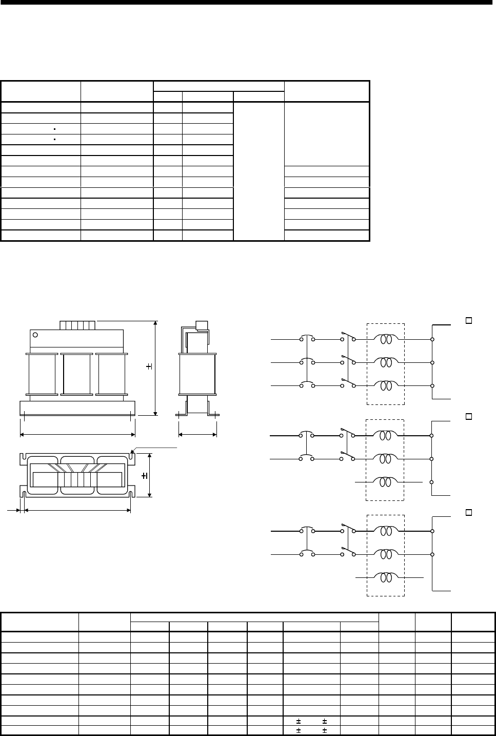
13 - 42
13. OPTIONS AND AUXILIARY EQUIPMENT
13.2.2 No-fuse breakers, fuses, magnetic contactors
Always use one no-fuse breaker and one magnetic contactor with one servo amplifier. When using a fuse
instead of the no-fuse breaker, use the one having the specifications given in this section.
Fuse
Servo amplifier No-fuse breaker Class Current [A] Voltage [V] Magnetic contactor
MR-J2S-10A(1) 30A frame 5A K5 10
MR-J2S-20A 30A frame 5A K5 10
MR-J2S-40A 20A1 30A frame 10A K5 15
MR-J2S-60A 40A1 30A frame 15A K5 20
MR-J2S-70A 30A frame 15A K5 20
MR-J2S-100A 30A frame 15A K5 25
S-N10
MR-J2S-200A 30A frame 20A K5 40 S-N18
MR-J2S-350A 30A frame 30A K5 70 S-N20
MR-J2S-500A 50A frame 50A K5 125 S-N35
MR-J2S-700A 100A frame 75A K5 150 S-N50
MR-J2S-11KA 100A frame 100A K5 200 S-N65
MR-J2S-15KA 225A frame 125A K5 250 S-N95
MR-J2S-22KA 225A frame 175A K5 350
AC250
S-N25
13.2.3 Power factor improving reactors
The input power factor is improved to be about 90%. For use with a 1-phase power supply, it may be
slightly lower than 90%.
3-phase
200 to 230VAC
NFB
FR-BAL
R
S
T
X
Y
Z
L1
L2
L3
MC
1-phase
230VAC
NFB FR-BAL
R
S
T
X
Y
Z
L1
L2
L3
MC
1-phase
100 to120VAC
NFB
FR-BAL
R
S
T
X
Y
Z
L1
L2
MC
W
W1C
RXSYTZ
H 5
D1
Installation screw
D 5
[Unit : mm]
(Note)
Servo amplifier
MR-J2S- A
Servo amplifier
MR-J2S- A
Servo amplifier
MR-J2S- A1
Note. For the 1-phase 230V power supply, Connect the power supply to L1, L2 and leave L3 open.
Dimensions [mm (in) ]
Servo amplifier Model WW1H D D1 C
Mounting
screw size Terminal
screw size Mass
[kg (lb)]
MR-J2S-10A(1)/20A FR-BAL-0.4K 135 (5.31) 120 (4.72) 115 (4.53) 59 (2.32) 45 0
-2.5 (1.77 0
-0.098)7.5 (0.29) M4 M3.5 2.0 (4.4)
MR-J2S-40A/20A1 FR-BAL-0.75K 135 (5.31) 120 (4.72) 115 (4.53) 69 (2.72) 57 0
-2.5 (2.24 0
-0.098)7.5 (0.29) M4 M3.5 2.8 (6.17)
MR-J2S-60A/70A/40A1 FR-BAL-1.5K 160 (6.30) 145 (5.71) 140 (5.51) 71 (2.79) 55 0
-2.5 (2.17 0
-0.098)7.5 (0.29) M4 M3.5 3.7 (8.16)
MR-J2S-100A FR-BAL-2.2K 160 (6.30) 145 (5.71) 140 (5.51) 91 (3.58) 75 0
-2.5 (2.95 0
-0.098)7.5 (0.29) M4 M3.5 5.6 (12.35)
MR-J2S-200A FR-BAL-3.7K 220 (8.66) 200 (7.87) 192 (7.56) 90 (3.54) 70 0
-2.5 (2.76 0
-0.098)10 (0.39) M5 M4 8.5 (18.74)
MR-J2S-350A FR-BAL-7.5K 220 (8.66) 200 (7.87) 194 (7.64) 120 (4.72) 100 0
-2.5 (3.94 0
-0.098)10 (0.39) M5 M5 14.5 (32.0)
MR-J2S-500A FR-BAL-11K 280 (11.02) 255 (10.04) 220 (8.66) 135 (5.31) 100 0
-2.5 (3.94 0
-0.098)12.5 (0.49) M6 M6 19 (41.9)
MR-J2S-700A/11KA FR-BAL-15K 295 (11.61) 270 (10.62) 275 (10.83) 133 (5.24) 110 0
-2.5 (4.33 0
-0.098)12.5 (0.49) M6 M6 27 (59.5)
MR-J2S-15KA FR-BAL-22K 290 (11.41) 240 (9.75) 301 (11.85) 199 (7.84) 170 5 (6.69 0.2) 25 (0.98) M8 M8 35 (77.16)
MR-J2S-22KA FR-BAL-30K 290 (11.41) 240 (9.75) 301 (11.85) 219 (8.62) 190 5 (7.48 0.2) 25 (0.98) M8 M8 43 (94.79)
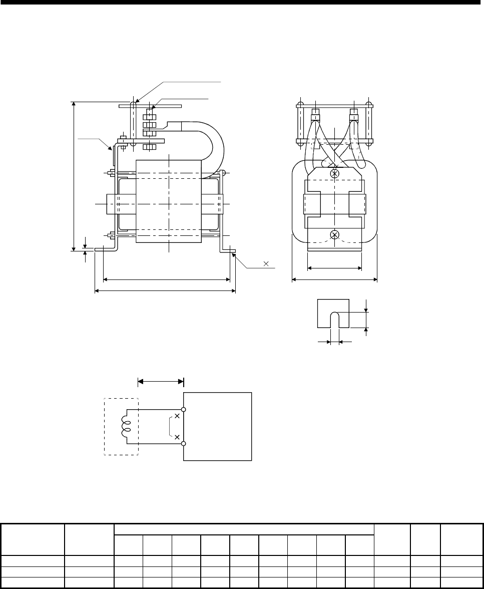
13 - 43
13. OPTIONS AND AUXILIARY EQUIPMENT
13.2.4 Power factor improving DC reactors
The input power factor is improved to be about 95%.
Screw size G
(Note 1) Terminal cover
2-F L
Notch
A or less
E
Name plate
C or less
D
B or less
H
F
L
Mounting foot part
FR-BEL
P
P1
Servo amplifier
(Note2)
Note1. Fit the supplied terminal cover after wiring.
2. When using the DC reactor, remove the short-circuit bar across P-P1.
5m or less
Dimensions [mm (in) ]
Servo amplifier
Power factor
improving DC
reactors ABCDEFLGH
Terminal
screw size
Mass
[kg (lb)]
Used wire
[mm2]
MR-J2S-11KA FR-BEL-15K 170(6.69
)
93(3.66) 170(6.69
)
2.3(0.09)155(6.10) 6(0.24) 14(0.55) M8 56(2.21) M5 3.8(8.38) 22(AWG4)
MR-J2S-15KA FR-BEL-22K 185(7.28
)
119(4.69
)
182(7.17
)
2.6(0.10)165(6.49) 7(0.28) 15(0.59) M8 70(2.77) M6
5.4(11.91)
30(AWG2)
MR-J2S-22KA FR-BEL-30K 185(7.28
)
119(4.69
)
2
01(7.91
)
2.6(0.10)165(6.49) 7(0.28) 15(0.59) M8 70(2.77) M6
6.7(14.77)
60(AWG1/0)
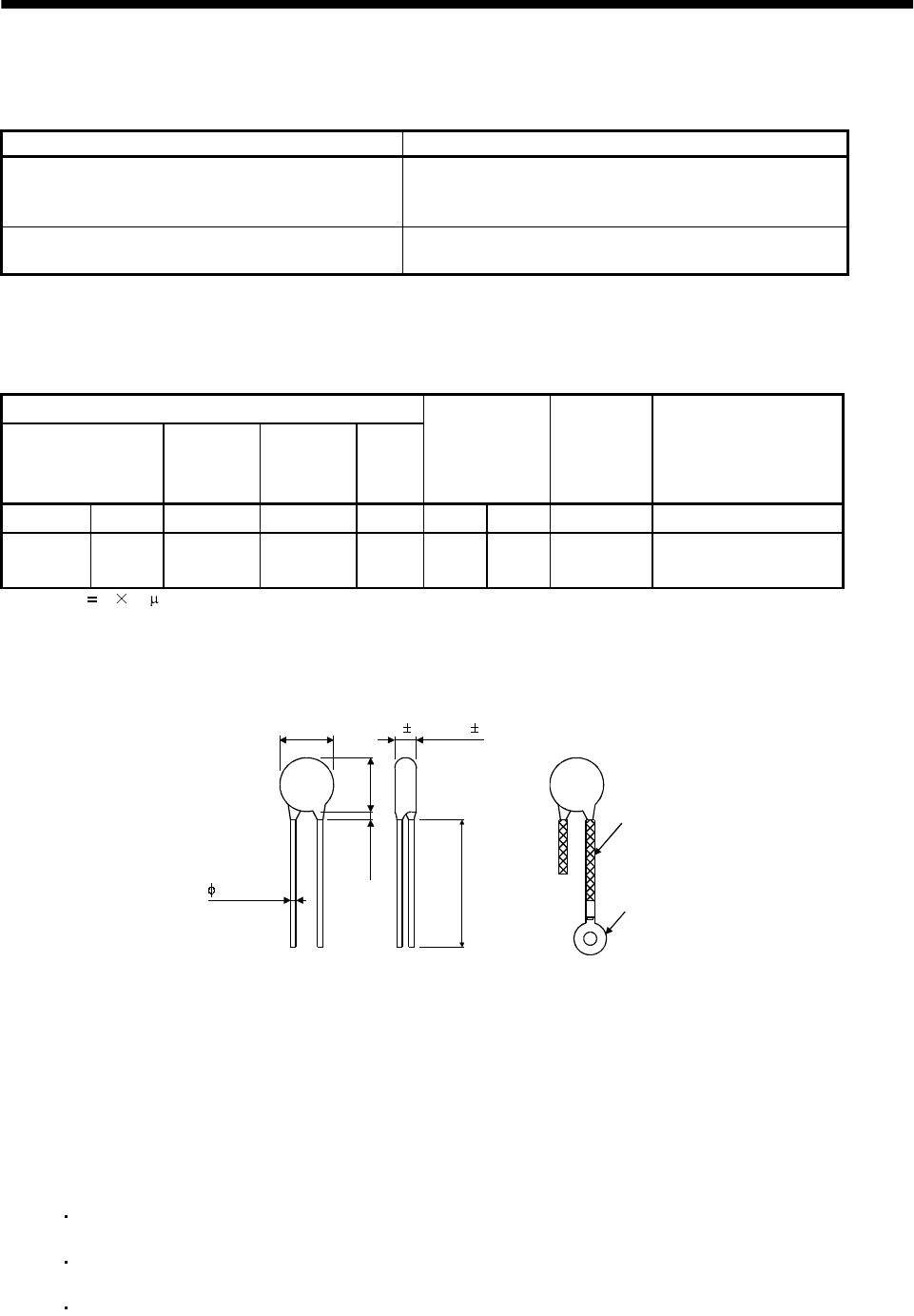
13 - 44
13. OPTIONS AND AUXILIARY EQUIPMENT
13.2.5 Relays
The following relays should be used with the interfaces:
Interface Selection example
Relay used for digital input command signals (interface
DI-1) To prevent defective contacts , use a relay for small signal
(twin contacts).
(Ex.) Omron : type G2A , MY
Relay used for digital output signals (interface DO-1) Small relay with 12VDC or 24VDC of 40mA or less
(Ex.) Omron : type MY
13.2.6 Surge absorbers
A surge absorber is required for the electromagnetic brake. Use the following surge absorber or equivalent.
Insulate the wiring as shown in the diagram.
Maximum rating
Permissible circuit
voltage
Surge
immunity
Energy
immunity
Rated
power
Maximum
limit voltage
Static
capacity
(reference
value)
Varistor voltage
rating (range) V1mA
AC[Vma] DC[V] [A] [J] [W] [A] [V] [pF] [V]
140 180 (Note)
500/time 5 0.4 25 360 300 220
(198 to 242)
Note. 1 time 8 20 s
(Example) ERZV10D221 (Matsushita Electric Industry)
TNR-10V221K (Nippon chemi-con)
Outline drawing [mm] ( [in] ) (ERZ-C10DK221)
13.5 (0.53)
16.5
(0.65)
3.0 (0.12)
or less
30.0 (1.18)
or more
Crimping terminal
for M4 screw
Vinyl tube
4.7 1.0 (0.19 0.04)
0.8 (0.03)
13.2.7 Noise reduction techniques
Noises are classified into external noises which enter the servo amplifier to cause it to malfunction and
those radiated by the servo amplifier to cause peripheral devices to malfunction. Since the servo amplifier
is an electronic device which handles small signals, the following general noise reduction techniques are
required.
Also, the servo amplifier can be a source of noise as its outputs are chopped by high carrier frequencies. If
peripheral devices malfunction due to noises produced by the servo amplifier, noise suppression measures
must be taken. The measures will vary slightly with the routes of noise transmission.
(1) Noise reduction techniques
(a) General reduction techniques
Avoid laying power lines (input and output cables) and signal cables side by side or do not bundle
them together. Separate power lines from signal cables.
Use shielded, twisted pair cables for connection with the encoder and for control signal
transmission, and connect the shield to the SD terminal.
Ground the servo amplifier, servo motor, etc. together at one point (refer to Section 3.10).
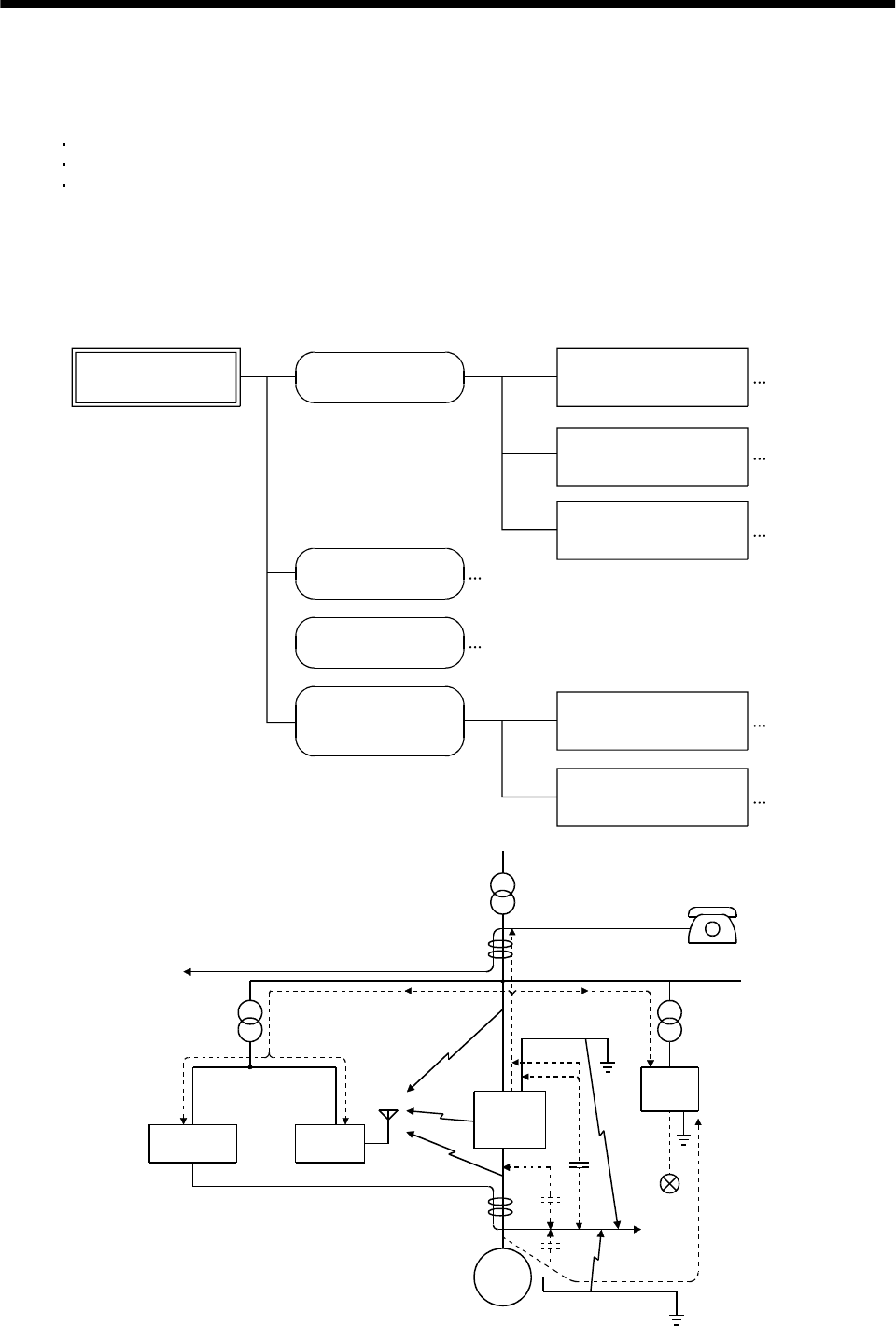
13 - 45
13. OPTIONS AND AUXILIARY EQUIPMENT
(b) Reduction techniques for external noises that cause the servo amplifier to malfunction
If there are noise sources (such as a magnetic contactor, an electromagnetic brake, and many
relays which make a large amount of noise) near the servo amplifier and the servo amplifier may
malfunction, the following countermeasures are required.
Provide surge absorbers on the noise sources to suppress noises.
Attach data line filters to the signal cables.
Ground the shields of the encoder connecting cable and the control signal cables with cable clamp
fittings.
(c) Techniques for noises radiated by the servo amplifier that cause peripheral devices to malfunction
Noises produced by the servo amplifier are classified into those radiated from the cables connected
to the servo amplifier and its main circuits (input and output circuits), those induced
electromagnetically or statically by the signal cables of the peripheral devices located near the
main circuit cables, and those transmitted through the power supply cables.
Noises produced
by servo amplifier Noises transmitted
in the air Noise radiated directly
from servo amplifier
Magnetic induction
noise
Static induction
noise
Noises transmitted
through electric
channels
Noise radiated from the
power supply cable
Noise radiated from
servo motor cable
Noise transmitted through
power supply cable
Noise sneaking from
grounding cable due to
leakage current
Routes 4) and 5)
Route 1)
Route 2)
Route 3)
Route 7)
Route 8)
Route 6)
Instrument Receiver
Servo
amplifier
Servo motor M
2)
2)
8)
1)
7)
7) 7)
5)
3)
4)
6)
3)
Sensor
power
supply
Sensor

13 - 46
13. OPTIONS AND AUXILIARY EQUIPMENT
Noise transmission route Suppression techniques
1) 2) 3)
When measuring instruments, receivers, sensors, etc. which handle weak signals and may
malfunction due to noise and/or their signal cables are contained in a control box together with the
servo amplifier or run near the servo amplifier, such devices may malfunction due to noises
transmitted through the air. The following techniques are required.
1. Provide maximum clearance between easily affected devices and the servo amplifier.
2. Provide maximum clearance between easily affected signal cables and the I/O cables of the servo
amplifier.
3. Avoid laying the power lines (Input cables of the servo amplifier) and signal cables side by side or
bundling them together.
4. Insert a line noise filter to the I/O cables or a radio noise filter on the input line.
5. Use shielded wires for signal and power cables or put cables in separate metal conduits.
4) 5) 6)
When the power lines and the signal cables are laid side by side or bundled together, magnetic
induction noise and static induction noise will be transmitted through the signal cables and
malfunction may occur. The following techniques are required.
1. Provide maximum clearance between easily affected devices and the servo amplifier.
2. Provide maximum clearance between easily affected signal cables and the I/O cables of the servo
amplifier.
3. Avoid laying the power lines (I/O cables of the servo amplifier) and signal cables side by side or
bundling them together.
4. Use shielded wires for signal and power cables or put the cables in separate metal conduits.
7)
When the power supply of peripheral devices is connected to the power supply of the servo
amplifier system, noises produced by the servo amplifier may be transmitted back through the
power supply cable and the devices may malfunction. The following techniques are required.
1. Insert the radio noise filter (FR-BIF) on the power cables (Input cables) of the servo amplifier.
2. Insert the line noise filter (FR-BSF01 FR-BLF) on the power cables of the servo amplifier.
8) When the cables of peripheral devices are connected to the servo amplifier to make a closed loop
circuit, leakage current may flow to malfunction the peripheral devices. If so, malfunction may be
prevented by disconnecting the grounding cable of the peripheral device.
(2) Noise reduction products
(a) Data line filter
Noise can be prevented by installing a data line filter onto the encoder cable, etc.
For example, the ZCAT3035-1330 of TDK and the ESD-SR-25 of NEC Tokin make are available as
data line filters.
As a reference example, the impedance specifications of the ZCAT3035-1330 (TDK) are indicated
below.
This impedances are reference values and not guaranteed values.
Impedance[ ]
10 to 100MHz 100 to 500MHz
80 150
Outline drawin
g
(
ZCAT3035-1330
)
[Unit: mm]([Unit: in.])
Loop for fixing the
cable band
Lot number Product name
TDK
39 1(1.54 0.04)
34 1
(1.34 0.04)
13 1
(0.51 0.04)
30 1
(1.18 0.04)
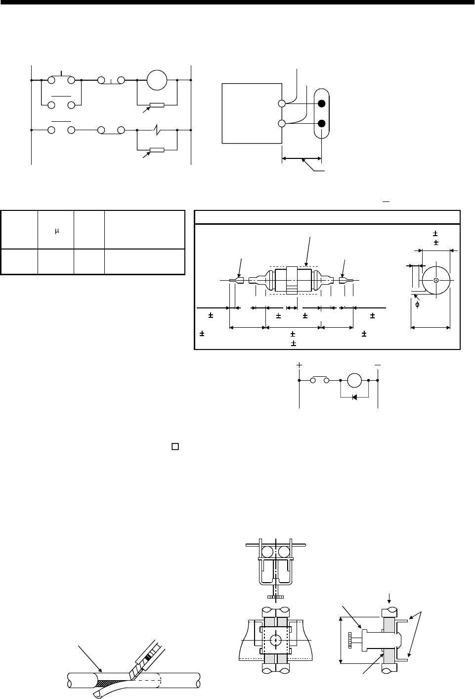
13 - 47
13. OPTIONS AND AUXILIARY EQUIPMENT
(b) Surge suppressor
The recommended surge suppressor for installation to an AC relay, AC valve, AC electromagnetic
brake or the like near the servo amplifier is shown below. Use this product or equivalent.
Relay
This distance should be shor
t
(within 20cm(0.79 in.)).
Surge suppressor
MC
Surge suppressor
Surge suppressor
(Ex.) 972A.2003 50411
(Matsuo Electric Co.,Ltd. 200VAC rating)
Outline drawing [Unit: mm] ([Unit: in.])
Rated
voltage
AC[V]
C [ F] R [Ω] Test voltage AC[V]
200 0.5 50
(1W) Across
T-C 1000(1 to 5s)
Blue vinyl cord Red vinyl cord
Vinyl sheath
200(7.87)
or more 200(7.87)
or more
6(0.24)
31(1.22)
10(0.39)or less 10(0.39)or less
15 1(0.59 0.04)
48 1.5
(
1.89 0.06
)
10 3
(0.39
0.15)
10 3
(0.39
0.12)
4(0.16)
18 1.5
(0.71 0.06)
Note that a diode should be installed to a DC relay, DC valve or
the like.
Maximum voltage: Not less than 4 times the drive voltage of
the relay or the like
Maximum current: Not less than twice the drive current of
the relay or the like
Diode
RA
(c) Cable clamp fitting (AERSBAN -SET)
Generally, the earth of the shielded cable may only be connected to the connector's SD terminal.
However, the effect can be increased by directly connecting the cable to an earth plate as shown
below.
Install the earth plate near the servo amplifier for the encoder cable. Peel part of the cable sheath
to expose the external conductor, and press that part against the earth plate with the cable clamp.
If the cable is thin, clamp several cables in a bunch.
The clamp comes as a set with the earth plate.
Strip the cable sheath of
the clamped area. cutter
cable
Cable clamp
(A,B)
Cable
Earth plate
External conductor
Clamp section diagram
40(1.57)
13 - 48
13. OPTIONS AND AUXILIARY EQUIPMENT
Outline drawing
Earth plate Clamp section diagram
(Note)M4 screw
11(0.43) 3 (0.12)
6 (0.24)
C
A
622(0.87)
17.5(0.69)
35(1.38)
35 (1.38)
L or less 10(0.39)
30
(
1.18
)
7 (0.28)
24
0
0.2
Note. Screw hole for
g
roundin
g
. Connect it to the earth
p
late of the control box.
(0.24)
24
0.3
0
(
0.940
)
(0.940)
[Unit: mm]
([Unit: in.])
B 0.3(0.01)
2- 5(0.20) hole
installation hole
Type A B C Accessory fittings Clamp fitting L
AERSBAN-DSET 100
(3.94) 86
(3.39) 30
(1.18) clamp A: 2pcs. A 70
(2.76)
AERSBAN-ESET 70
(2.76) 56
(2.20) clamp B: 1pc. B 45
(1.77)
13 - 49
13. OPTIONS AND AUXILIARY EQUIPMENT
(d) Line noise filter (FR-BLF, FR-BSF01)
This filter is effective in suppressing noises radiated from the power supply side and output side of
the servo amplifier and also in suppressing high-frequency leakage current (zero-phase current)
especially within 0.5MHz to 5MHz band.
Connection diagram Outline drawing [Unit: mm] ([Unit: in.])
4.5(0.18)
Approx.110(4.33)
Approx 22.5(0.89)
Approx.65(2.56)
Approx.65(2.56)
2- 5(0.20)
Approx.95 0.5(3.74 0.02)
33(1.30)
11.25 0.5
FR-BSF01(for MR-J2S-200A or less)
(0.44 0.02)
Wind the 3-phase wires by the equal number of times in the
same direction, and connect the filter to the power supply side
and output side of the servo amplifier.
The effect of the filter on the power supply side is higher as the
number of winds is larger. The number of turns is generally four.
If the wires are too thick to be wound, use two or more filters
and make the total number of turns as mentioned above.
On the output side, the number of turns must be four or less.
Do not wind the grounding wire together with the 3-phase wires.
The filter effect will decrease. Use a separate wire for grounding.
Example 2
Two filters are used
(Total number of turns: 4)
Power
supply
Servo amplifier
Line noise
filter
NFB
L3
L1
L2
Example 1
(Number of turns: 4)
Power
supply
NFB
L1
L2
L3
Servo amplifier
Line noise
filter
MC
MC
160(6.30)
180(7.09)
130(5.12)
85(3.35)
80(3.15)
2.3(0.09)
35
(1.38)
31.5(1.24)
7(0.28)
7(0.28)
FR-BLF(MR-J2S-350A or more)
(e) Radio noise filter (FR-BIF)...for the input side only
This filter is effective in suppressing noises radiated from the power supply side of the servo
amplifier especially in 10MHz and lower radio frequency bands. The FR-BIF is designed for the
input only.
Connection diagram Outline drawing (Unit: mm) ([Unit: in.])
Make the connection cables as short as possible.
Grounding is always required.
When using the FR-BIF with a single-phase wire,
always insulate the wires that are not used for wiring.
Servo amplifier
NFB
L3
L2
L1
MC
Power
supply
Radio noise
filter FR-BIF
Leakage current: 4mA
29 (1.14)
58 (2.28)
42 (1.65)
4 (0.16)
Red BlueWhite Green
44
(
1.73
)
29 (1.14) 7 (0.28)
hole
About 300(11.81)
5 (0.20)
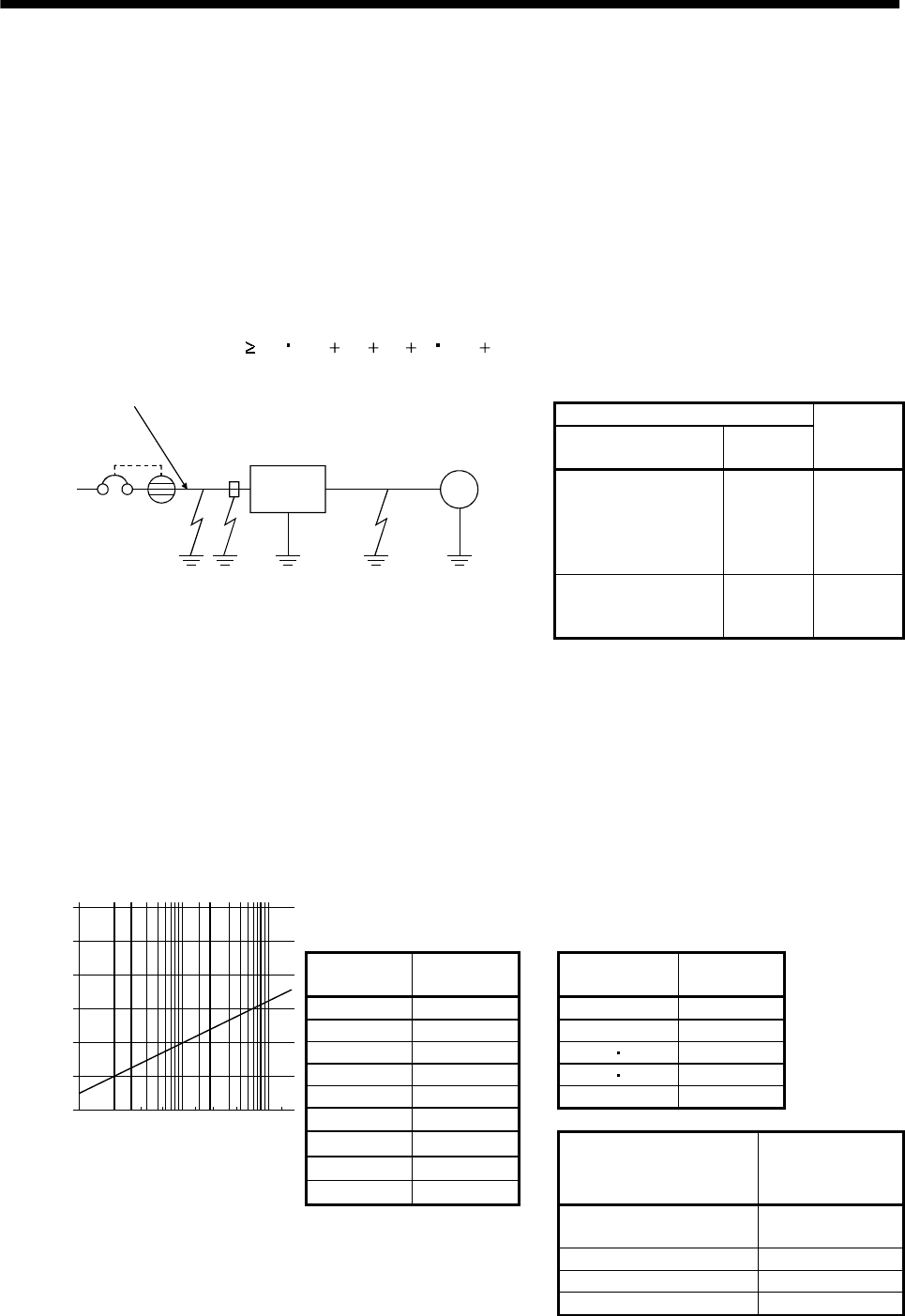
13 - 50
13. OPTIONS AND AUXILIARY EQUIPMENT
13.2.8 Leakage current breaker
(1) Selection method
High-frequency chopper currents controlled by pulse width modulation flow in the AC servo circuits.
Leakage currents containing harmonic contents are larger than those of the motor which is run with a
commercial power supply.
Select a leakage current breaker according to the following formula, and ground the servo amplifier,
servo motor, etc. securely.
Make the input and output cables as short as possible, and also make the grounding cable as long as
possible (about 30cm (11.8 in)) to minimize leakage currents.
Rated sensitivity current 10 {Ig1 Ign Iga K(Ig2 Igm)} [mA] ..........(13.2)
K: Constant considering the harmonic contents
Leakage current breaker
Type Mitsubishi
products
K
Models provided with
harmonic and surge
reduction techniques
NV-SP
NV-SW
NV-CP
NV-CW
NV-L
1
General models BV-C1
NFB
NV-L 3
M
Servo
amplifier
Noise
filter
NV
Ig1 Ign Iga Ig2 Igm
Cable
Cable
Ig1: Leakage current on the electric channel from the leakage current breaker to the input terminals
of the servo amplifier (Found from Fig. 13.1.)
Ig2: Leakage current on the electric channel from the output terminals of the servo amplifier to the
servo motor (Found from Fig. 13.1.)
Ign: Leakage current when a filter is connected to the input side (4.4mA per one FR-BIF)
Iga: Leakage current of the servo amplifier (Found from Table 13.6.)
Igm: Leakage current of the servo motor (Found from Table 13.5.)
Table 13.5 Servo motor's
leakage current
example (Igm)
Table 13.6 Servo amplifier's
leakage current
example (Iga)
Servo motor
output [kW]
Leakage
current [mA]
Servo amplifier
capacity [kW]
Leakage
current [mA]
0.05 to 0.5 0.1 0.1 to 0.6 0.1
0.6 to 1.0 0.1 0.7 to 3.5 0.15
1.2 to 2.2 0.2 5 72
3 to 3.5 0.3 11 15 5.5
50.5 22 7
70.7
Table 13.7 Leakage circuit breaker selection example
11 1.0
15 1.3
22 2.3
Servo amplifier
Rated sensitivity
current of leakage
circuit breaker [mA]
MR-J2S-10A to MR-J2S-350A
MR-J2S-10A1 to MR-J2S-40A1 15
MR-J2S-500A 30
MR-J2S-700A 50
120
100
80
60
40
20
023.5
5.5
81422388015
0
30 60 100
Fig. 13.1 Leakage current example
(Ig1, Ig2) for CV cable run
in metal conduit
Cable size[mm2]
[mA]
Leakage current
MR-J2S-11KA to MR-J2S-22KA 100
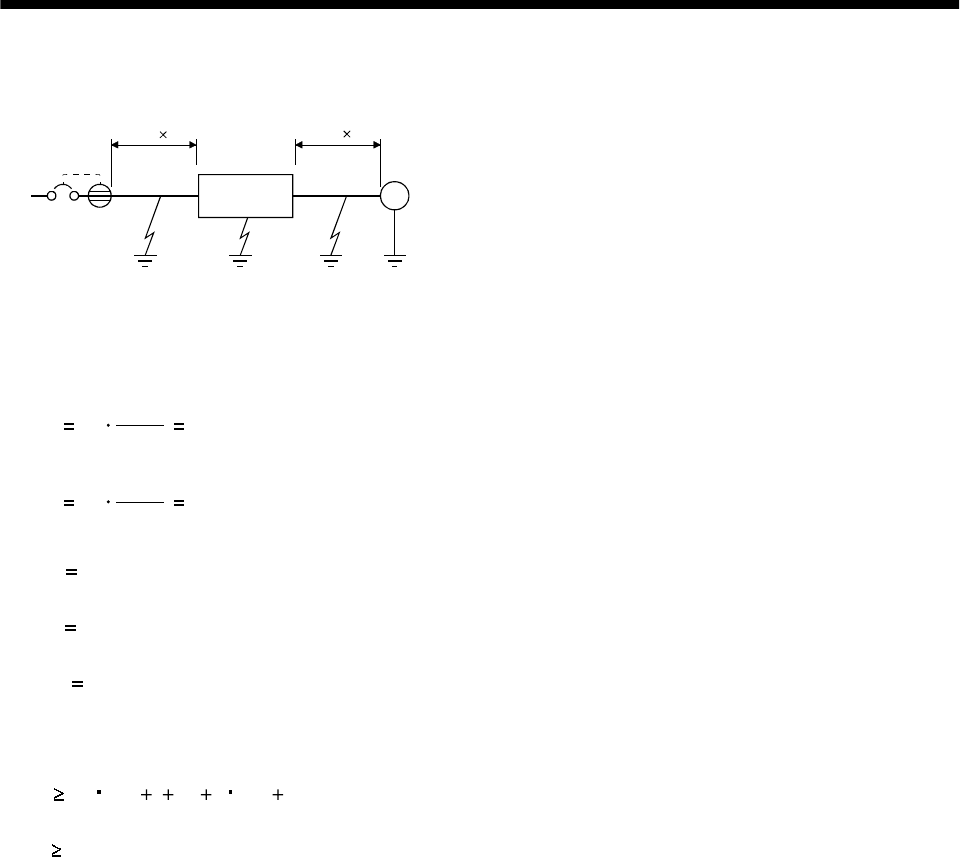
13 - 51
13. OPTIONS AND AUXILIARY EQUIPMENT
(2) Selection example
Indicated below is an example of selecting a leakage current breaker under the following conditions:
M
NV
Ig1 Iga Ig2 Igm
Servo
amplifier
MR-J2S-60A
2mm2 5m 2mm2 5m
Servo motor
HC-MFS73
Use a leakage current breaker generally available.
Find the terms of Equation (13.2) from the diagram:
Ig1 20 1000
50.1 [mA]
Ig2 20 1000
50.1 [mA]
Ign 0 (not used)
Iga 0.1 [mA]
Igm 0.1 [mA]
Insert these values in Equation (13.2):
Ig 10 {0.1 00.1 1(0.1 0.1)}
4.0 [mA]
According to the result of calculation, use a leakage current breaker having the rated sensitivity
current (Ig) of 4.0[mA] or more. A leakage current breaker having Ig of 15[mA] is used with the NV-
SP/SW/CP/CW/HW series.
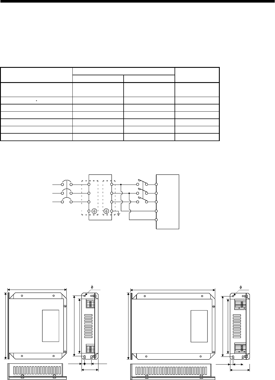
13 - 52
13. OPTIONS AND AUXILIARY EQUIPMENT
13.2.9 EMC filter
For compliance with the EMC directive of the EN Standard, it is recommended to use the following filter:
Some EMC filters are large in leakage current.
(1) Combination with the servo amplifier
Recommended filter
Servo amplifier Model Leakage current [mA] Mass [kg]([lb])
MR-J2S-10A to MR-J2S-100A
MR-J2S-10A1 to MR-J2S-40A1 SF1252 38 0.75(1.65)
MR-J2S-200A MR-J2S-350A SF1253 57 1.37(3.02)
MR-J2S-500A (Note) HF3040A-TM 1.5 5.5(12.13)
MR-J2S-700A (Note) HF3050A-TM 1.5 6.7(14.77)
MR-J2S-11KA (Note) HF3060A-TMA 3.0 10.0(22.05)
MR-J2S-15KA (Note) HF3080A-TMA 3.0 13.0(28.66)
MR-J2S-22KA (Note) HF3100A-TMA 3.0 14.5(31.97)
Note: Soshin Electric A surge protector is separately required to use any of these EMC filters. (Refer to the EMC Installation
Guidelines.)
(2) Connection example
NFB
L1
L2
L3
L11
L21
L1
L2
L3
LINE LOAD
EMC filter Servo amplifier
(Note 1)
Power supply
(Note 2)
Note 1. For 1-phase 230VAC power supply, connect the power supply to L1,L2 and leave L3 open.
There is no L3 for 1-phase 100 to 120VAC power supply.
2. Connect when the power supply has earth.
L1
L2
L3
MC
(3) Outline drawing
23.0(0.906)
LABEL
LINELOAD
168.0(6.614)
L1'
L2'
L3'
L1
L2
L3
149.5(5.886)
LINE
(input side)
LOAD
(output side)
140.0(5.512)
156.0(6.142)
16.0(0.63)
42.0
8.5
SF1252
LABEL
LINELOAD
168.0(6.614)
L1'
L2'
L3'
L1
L2
L3
209.5(8.248)
LINE
(input side)
LOAD
(output side)
140.0(5.512)
156.0(6.142)
49.0
8.5
SF1253 [Unit: mm(in)]
(0.335)
(1.654)
(0.335)
(1.929)
6.0(0.236) 6.0(0.236)
13 - 53
13. OPTIONS AND AUXILIARY EQUIPMENT
HF3040A-TM HF3050A-TM HF3060A-TMA
H 2
J 2
G 1
F 2
E 1
D 2
3-L
6-K
3-L
M
C 1
B 2
A 5
C 1
Dimensions [mm(in)]
Model ABCDEFGHJKLM
HF3040A-TM 260
(10.24) 210
(8.27) 85
(8.35) 155
(6.10) 140
(5.51) 125
(4.92) 44
(1.73) 140
(5.51) 70
(2.76) M5 M4
HF3050A-TM 290
(11.42) 240
(9.45) 100
(3.94) 190
(7.48) 175
(6.89) 160
(6.29) 44
(1.73) 170
(6.69) 100
(3.94) M6 M4
HF3060A-TMA 290
(11.42) 240
(9.45) 100
(3.94) 190
(7.48) 175
(6.89) 160
(6.29) 44
(1.73) 230
(9.06) 160
(6.29)
R3.25
(0.13),
length
8 (0.32) M6 M4
HF3080A-TMA HF3100A-TMA
H 2
J 2
G 1
F 2
E 1
D 2
3-L
8-K
3-L
M
C 1
B 2
A 5
C 1 C 1
Dimensions [mm(in)]
Model ABCDEFGHJKLM
HF3080A-TMA
HF3100A-TMA
405
(15.95) 350
(13.78) 100
(3.94) 220
(8.66) 200
(7.87) 180
(7.09) 56
(2.21) 210
(8.27) 135
(5.32)
R4.25
(0.17),
length 12
(0.47)
M8 M6
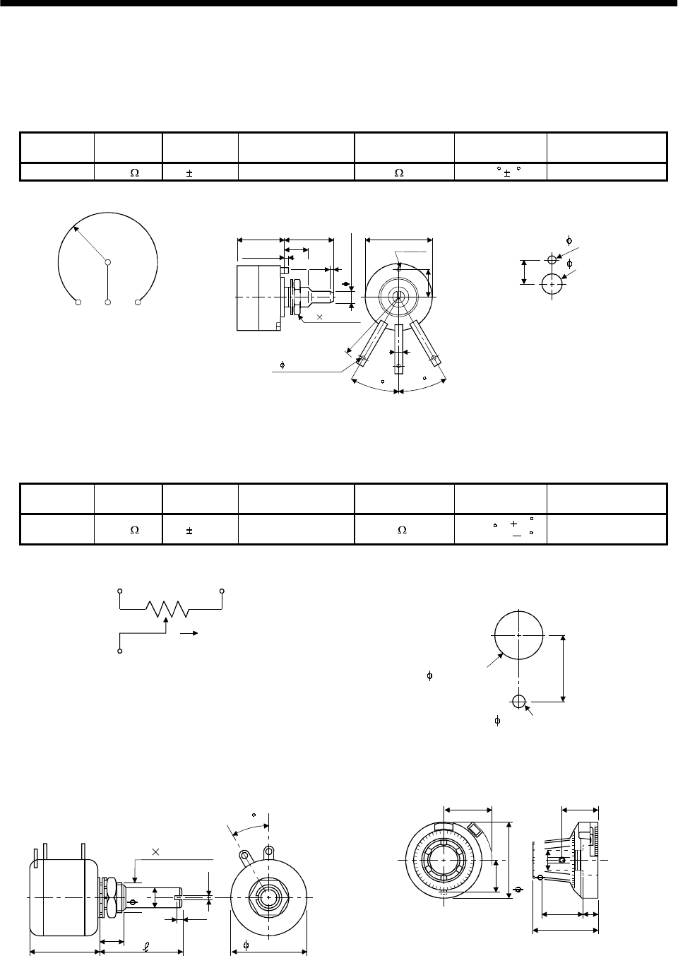
13 - 54
13. OPTIONS AND AUXILIARY EQUIPMENT
13.2.10 Setting potentiometers for analog inputs
The following variable resistors are available for use with analog inputs.
(1) Single-revolution type
WA2WYA2SEBK2KΩ (Japan Resistor make)
Rated power Resistance Resistance
tolerance
Dielectric strength
(for 1 minute)
Insulation
resistance
Mechanical
rotary angle Rotary torque
2W 2k 10% 700V A.C 100M or more 300 510 to 100g-cm or less
Connection diagram
123
Outline dimension drawing
20 (0.79) 30 (1.18)
12 (0.47)
3
(0.08)
R25 (0.98)
30
1
6 (0.24) hole
2.8 (0.11)
M9 0.75 (0.03)
30
2
3
3- 1.54 (0.56) hole
25 (0.98)
10 (0.39)
2.5 (0.10)
1.6 (0.06)
[Unit: mm (in)]
Panel hole machining diagram
12 (0.47)
10 (0.37) hole
3.6 (0.14) hole
[Unit: mm (in)]
(2) Multi-revolution type
Position meter: RRS10M202 (Japan Resistor make)
Analog dial: 23M (Japan Resistor make)
Rated power Resistance Resistance
tolerance
Dielectric strength
(for 1 minute)
Insulation
resistance
Mechanical
rotary angle Rotary torque
10
1W 2k 10% 700V A.C 1000M or more 3600 0100g-cm or less
Connection diagram
13
2
CW
Panel hole machining diagram
9.5 (0.37)
9 (0.35) hole
2.1 (0.08) hole
Panel thickness: 2 to 6 (0.08 to 0.24)
[Unit: mm (in)]
Outline dimension drawing
RRS10 M202
L7.5
1.2
1.0
2)1) 3)
2) 1)
3)
30
M9 0.75 (0.03)
6
(0.24)
(0.04)
(0.05)
(0.3) 23 (0.91)
[Unit: mm (in)] 23M
9.5
20.5
12 (0.47) 6 (0.24)
12.5 (0.49)
15 (0.59)
(0.81)
(0.37)
22.7 (0.89)
6(0.24)
[Unit: mm (in)]
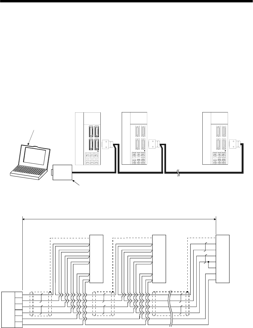
14 - 1
14. COMMUNICATION FUNCTIONS
14. COMMUNICATION FUNCTIONS
This servo amplifier has the RS-422 and RS-232C serial communication functions. These functions can be
used to perform servo operation, parameter changing, monitor function, etc.
However, the RS-422 and RS-232C communication functions cannot be used together. Select between RS-
422 and RS-232C with parameter No.16. (Refer to Section 14.2.2.)
14.1 Configuration
14.1.1 RS-422 configuration
(1) Outline
Up to 32 axes of servo amplifiers from stations 0 to 31 can be operated on the same bus.
CHARGE
MITSUBISHI
CHARGE
MITSUBISHI
CHARGE
MITSUBISHI
RS-422
Controller such as
personal computer
RS-232C/
RS-422
converter
To CN3
Axis 1 (Station 0) Axis 2 (Station 1) Axis 32 (Station 31)
Unavailable as option.
To be prepared by customer.
To CN3 To CN3
Servo amplifier Servo amplifier Servo amplifier
(2) Cable connection diagram
Wire as shown below:
RS-422
output unit
RDP
RDN
SDP
SDN
GND
GND
(Note 3) 30m (98.4ft) or less
(Note 1)
Axis 1 servo amplifier
CN3 connector
5
15
9
19
11
1
10
Plate
RDP
RDN
SDP
SDN
LG
LG
TRE
SD
(Note 1)
Axis 2 servo amplifier
CN3 connector
5
15
9
19
11
1
10
RDP
RDN
SDP
SDN
LG
LG
TRE
SD
Plate
(Note 1)
Axis 32 (last axis)
servo amplifier
CN3 connector
5
15
9
19
11
1
10
RDP
RDN
SDP
SDN
LG
LG
TRE
SDPlate
(Note 2)
Note 1. Connector set MR-J2CN1 (3M)
Connector: 10120-3000VE
Shell kit: 10320-52F0-008
2. In the last axis, connect TRE and RDN.
3. 30m (98.4ft) or less in environment of little noise.
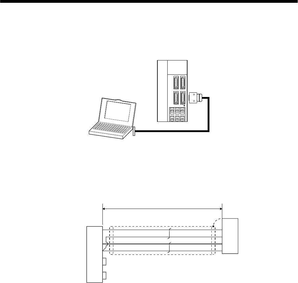
14 - 2
14. COMMUNICATION FUNCTIONS
14.1.2 RS-232C configuration
(1) Outline
A single axis of servo amplifier is operated.
CHARGE
MITSUBISHI
RS-232C
Controller such as
personal computer
Servo amplifier
To CN3
(2) Cable connection diagram
Wire as shown below. The communication cable for connection with the personal computer (MR-
CPCATCBL3M) is available. (Refer to Section 13.1.4.)
Personal computer
connector D-SUB9 (socket)
TXD
RXD
GND
RTS
CTS
3
2
5
7
8
DSR
DTR
6
4
(Note 1)
Servo amplifier
CN3 connector
TXD
GND
RXD
GND
FG
12
11
2
1
Plate
(Note 2) 15m (49.2ft) or less
Note 1. Connector set MR-J2CN1 (3M)
Connector: 10120-6000EL
Shell kit: 10320-3210-000
2. 15m (49.2ft) or less in environment of little noise. However, this distance should be 3m (9.84ft) or less for use at 38400bps
or more baudrate.
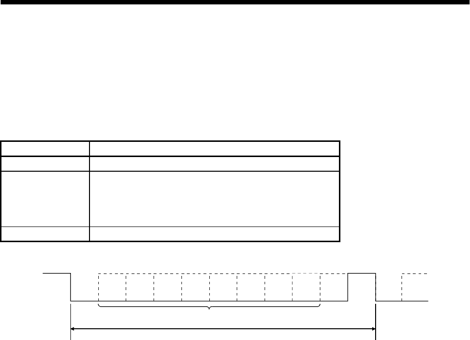
14 - 3
14. COMMUNICATION FUNCTIONS
14.2 Communication specifications
14.2.1 Communication overview
This servo amplifier is designed to send a reply on receipt of an instruction. The device which gives this
instruction (e.g. personal computer) is called a master station and the device which sends a reply in
response to the instruction (servo amplifier) is called a slave station. When fetching data successively, the
master station repeatedly commands the slave station to send data.
Item Description
Baudrate 9600/19200/38400/57600 asynchronous system
Transfer code
Start bit : 1 bit
Data bit : 8 bits
Parity bit : 1 bit (even)
Stop bit : 1 bit
Transfer protocol Character system, half-duplex communication system
1 frame (11bits)
Data
01234567
(LSB) (MSB)
Start Parity Stop
Next
start

14 - 4
14. COMMUNICATION FUNCTIONS
14.2.2 Parameter setting
When the RS-422/RS-232C communication function is used to operate the servo, set the communication
specifications of the servo amplifier in the corresponding parameters.
After setting the values of these parameters, they are made valid by switching power off once, then on
again.
(1) Serial communication baudrate
Choose the communication speed. Match this value to the communication speed of the sending end
(master station).
Communication baudrate
0: 9600[bps]
1: 19200[bps]
2: 38400[bps]
3: 57600[bps]
Parameter No. 16
(2) Serial communication selection
Select the RS-422 or RS-232C communication standard. RS-422 and RS-232C cannot be used together.
Serial communication standard selection
0: RS-232C used
1: RS-422 used
Parameter No. 16
(3) Serial communication response delay time
Set the time from when the servo amplifier (slave station) receives communication data to when it
sends back data. Set "0" to send back data in less than 800 s or "1" to send back data in 800 s or more.
Serial communication response delay time
0: Invalid
1: Valid, reply sent in 800 s or more
Parameter No. 16
(4) Station number setting
Set the station number of the servo amplifier in parameter No. 15. The setting range is stations 0 to 31.
(5) Protocol station number selection
When communication is made without setting station numbers to servo amplifiers as in the MR-J2-A
servo amplifiers, choose "no station numbers" in parameter No. 53. The communication protocol will
be free of station numbers.
Parameter No. 53
Protocol station number selection
0: With station numbers
1: No station numbers
14 - 5
14. COMMUNICATION FUNCTIONS
14.3 Protocol
POINT
Whether station number setting will be made or not must be selected if
the RS-232C communication function is used. Note that choosing "no
station numbers" in parameter No. 53 will make the communication
protocol free of station numbers as in the MR-J2-A servo amplifiers.
Since up to 32 axes may be connected to the bus, add a station number to the command, data No., etc. to
determine the destination servo amplifier of data communication. Set the station number to each servo
amplifier using the parameter. Transmission data is valid for the servo amplifier of the specified station
number or group.
When "*" is set as the station number added to the transmission data, the transmission data is made
valid for all servo amplifiers connected. However, when return data is required from the servo amplifier
in response to the transmission data, set "0" to the station number of the servo amplifier which must
provide the return data.
(1) Transmission of data from the controller to the servo
S
O
H
S
T
X
E
T
X
S
T
X
E
T
X
Data
No. Data* Check
sum
10 frames (data)
Station number
Error code
Check
sum
6 frames
Positive response: Error code A
Negative response: Error code other than A
Servo side
(Slave station)
Controller side
(Master station)
Command
Station number
14 - 6
14. COMMUNICATION FUNCTIONS
(2) Transmission of data request from the controller to the servo
S
O
H
S
T
X
E
T
X
S
T
X
E
T
X
Controller side
(Master station)
Servo side
(Slave station)
10 frames
Command
Data
No.
Check
sum
Error code
Data* Check
sum
6 frames (data)
Station number
Station number
(3) Recovery of communication status by time-out
E
O
T
Controller side
(Master station)
Servo side
(Slave station)
EOT causes the servo to return to
the receive neutral status.
(4) Data frames
The data length depends on the command.
or
Data
4 frames
Data
8 frames
or 12 frames or 16 frames
14 - 7
14. COMMUNICATION FUNCTIONS
14.4 Character codes
(1) Control codes
Code name Hexadecimal
(ASCII code) Description Personal computer terminal key operation
(General)
SOH
STX
ETX
EOT
01H
02H
03H
04H
start of head
start of text
end of text
end of transmission
ctrl A
ctrl B
ctrl C
ctrl D
(2) Codes for data
ASCII unit codes are used.
b80 0 0 0000 0
b70 0 0 0111 1
b60 0 1 1001 1
b50 1 0 1010 1
b8 to
b5b4b3b2b1C
R0 1 2 3456 7
0000 0NULDLESpace0@P` p
0001 1SOHDC
1!1AQaq
0010 2STXDC
2“2BRbr
0011 3ETXDC
3#3CScs
0100 4 $ 4DTd t
0101 5 % 5EUe u
0110 6 & 6FVf v
0111 7 ‘ 7GWg w
1000 8 ( 8HXh x
1001 9 ) 9IYi y
1010 10 :JZj z
1011 11 ;K[k {
1100 12 , Ll|
1101 13 M]m }
1110 14 . N^n
1111 15 / ?O_oDEL
(3) Station numbers
You may set 32 station numbers from station 0 to station 31 and the ASCII unit codes are used to
specify the stations.
Station number 0123456789101112131415
ASCII code 0123456789ABCDEF
Station number 16 17 18 19 20 21 22 23 24 25 26 27 28 29 30 31
ASCII code GHI J KLMNOPQRSTUV
For example, "30H" is transmitted in hexadecimal for the station number of "0" (axis 1).
14 - 8
14. COMMUNICATION FUNCTIONS
14.5 Error codes
Error codes are used in the following cases and an error code of single-code length is transmitted.
On receipt of data from the master station, the slave station sends the error code corresponding to that
data to the master station.
The error code sent in upper case indicates that the servo is normal and the one in lower case indicates
that an alarm occurred.
Error code
Servo normal Servo alarm Error name Description Remarks
[A] [a] Normal operation Data transmitted was processed properly. Positive response
[B] [b] Parity error Parity error occurred in the transmitted data.
[C] [c] Checksum error Checksum error occurred in the transmitted data.
[D] [d] Character error Character not existing in the specifications was
transmitted.
[E] [e] Command error Command not existing in the specifications was
transmitted.
[F] [f] Data No. error Data No. not existing in the specifications was
transmitted.
Negative response
14.6 Checksum
The check sum is a ASCII-coded hexadecimal representing the lower two digits of the sum of ASCII-coded
hexadecimal numbers up to ETX, with the exception of the first control code (STX or SOH).
Check
Checksum range
ETXSTX or
SOH
Station number S
T
X
02H
[0]
30H
[A]
41H
[1]
31H
[2]
32H
[5]
35H
[F]
46H
E
T
X
[5] [2]
03H
30H 41H 31H 32H 35H 46H 03H
152H
(Example)
Lower 2 digits 52 is sent after conversion into ASCII code [5][2].
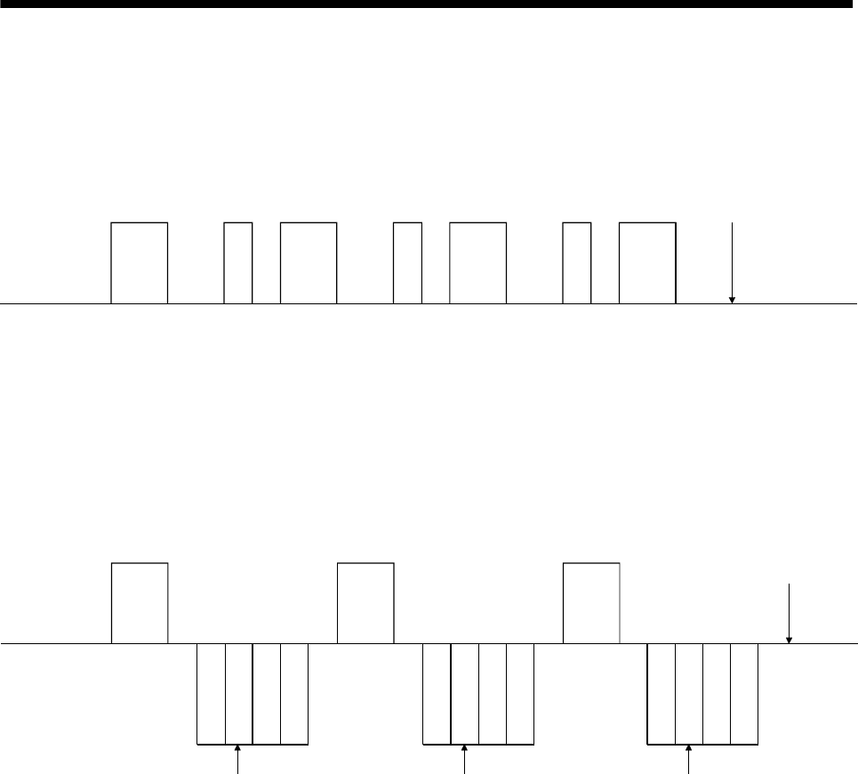
14 - 9
14. COMMUNICATION FUNCTIONS
14.7 Time-out operation
The master station transmits EOT when the slave station does not start reply operation (STX is not
received) 300[ms] after the master station has ended communication operation. 100[ms] after that, the
master station retransmits the message. Time-out occurs if the slave station does not answer after the
master station has performed the above operation three times. (Communication error)
E
O
T
300ms 100ms
E
O
T
300ms 100ms
E
O
T
300ms 100ms 300ms
Message
Message
Message
Message
*Time-out
Controller
(Master station)
Servo
(Slave station)
14.8 Retry operation
When a fault occurs in communication between the master and slave stations, the error code in the
response data from the slave station is a negative response code ([B] to [F], [b] to [f]). In this case, the
master station retransmits the message which was sent at the occurrence of the fault (Retry operation). A
communication error occurs if the above operation is repeated and results in the error three or more
consecutive times.
Message
Message
Message
*Communication error
Controller
(Master station)
Servo
(Slave station)
S
T
X
S
T
X
S
T
X
Station number Station number Station number
Similarly, when the master station detects a fault (e.g. checksum, parity) in the response data from the
slave station, the master station retransmits the message which was sent at the occurrence of the fault. A
communication error occurs if the retry operation is performed three times.
14 - 10
14. COMMUNICATION FUNCTIONS
14.9 Initialization
After the slave station is switched on, it cannot reply to communication until the internal initialization
processing terminates. Hence, at power-on, ordinary communication should be started after:
(1) 1s or more time has elapsed after the slave station is switched on; and
(2) Making sure that normal communication can be made by reading the parameter or other data which
does not pose any safety problems.
14.10 Communication procedure example
The following example reads the set value of parameter No.2 "function selection 1" from the servo
amplifier of station 0:
Data item Value Description
Station number 0 Servo amplifier station 0
Command 05 Read command
Data No. 02 Parameter No.2
Checksum 30H 30H 35H 02H 30H 32H 03H FCH
0 2STX ETX50
Yes
No
Yes
No
No
No
Yes
Yes
Yes
No
[0][0][5] [0][2]
[0]
Axis No. Command Data No.
Data
Start
Data make-up
Checksum calculation and
addition
Addition of SOH to make
up transmission data
Data transmission
Data receive
Is there receive data?
3 consecutive times?
Error processing
Other than error code
[A] [a]?
Receive data analysis
End
300ms elapsed?
3 consecutive times?
Error processing
100ms after EOT transmission
STX ETX
46H 43HSOH FCTransmission data 50 STX 02ETX
Master station slave station
Master station slave station
Master station slave station
0
14 - 11
14. COMMUNICATION FUNCTIONS
14.11 Command and data No. list
POINT
If the command/data No. is the same, its data may be different from the
interface and drive units and other servo amplifiers.
14.11.1 Read commands
(1) Status display (Command [0][1])
Command Data No. Description Display item Frame length
[0][1] [8][0] cumulative feedback pulses 12
[0][1] [8][1] servo motor speed 12
[0][1] [8][2] droop pulses 12
[0][1] [8][3] cumulative command pulses 12
[0][1] [8][4] command pulse frequency 12
[0][1] [8][5] analog speed command voltage
analog speed limit voltage 12
[0][1] [8][6] analog torque command voltage
analog torque limit voltage 12
[0][1] [8][7] regenerative load ratio 12
[0][1] [8][8] effective load ratio 12
[0][1] [8][9] peak load ratio 12
[0][1] [8][A] Instantaneous torque 12
[0][1] [8][B] within one-revolution position 12
[0][1] [8][C] ABS counter 12
[0][1] [8][D] load inertia moment ratio 12
[0][1] [8][E]
Status display data value and
processing information
Bus voltage 12
(2) Parameter (Command [0][5])
Command Data No. Description Frame length
[0][5] [0][0] to
[5][4] Current value of each parameter
The decimal equivalent of the data No. value (hexadecimal) corresponds
to the parameter number.
8
(3) External I/O signals (Command [1][2])
Command Data No. Description Frame length
[1][2] [4][0] External input pin statuses 8
[1][2] [C][0] External output pin statuses 8
(4) Alarm history (Command [3][3])
Command Data No. Description Alarm occurrence sequence Frame length
[3][3] [1][0] most recent alarm 4
[3][3] [1][1] first alarm in past 4
[3][3] [1][2] second alarm in past 4
[3][3] [1][3] third alarm in past 4
[3][3] [1][4] fourth alarm in past 4
[3][3] [1][5]
Alarm number in alarm history
fifth alarm in past 4
[3][3] [2][0] most recent alarm 8
[3][3] [2][1] first alarm in past 8
[3][3] [2][2] second alarm in past 8
[3][3] [2][3] third alarm in past 8
[3][3] [2][4] fourth alarm in past 8
[3][3] [2][5]
Alarm occurrence time in alarm
history
fifth alarm in past 8
14 - 12
14. COMMUNICATION FUNCTIONS
(5) Current alarm (Command [0][2] [3][5])
Command Data No. Description Frame length
[0][2] [0][0] Current alarm number 4
Command Data No. Description Display item Frame length
[3][5] [8][0] cumulative feedback pulses 12
[3][5] [8][1] servo motor speed 12
[3][5] [8][2] droop pulses 12
[3][5] [8][3] cumulative command pulses 12
[3][5] [8][4] command pulse frequency 12
[3][5] [8][5] analog speed command voltage
analog speed limit voltage 12
[3][5] [8][6] analog torque command voltage
analog torque limit voltage 12
[3][5] [8][7] regenerative load ratio 12
[3][5] [8][8] effective load ratio 12
[3][5] [8][9] peak load ratio 12
[3][5] [8][A] Instantaneous torque 12
[3][5] [8][B] within one-revolution position 12
[3][5] [8][C] ABS counter 12
[3][5] [8][D] load inertia moment ratio 12
[3][5] [8][E]
Status display data value and
processing information at alarm
occurrence
Bus voltage 12
(6) Others
Command Data No. Description Frame length
[0][2] [9][0] Servo motor end pulse unit absolute position 8
[0][2] [9][1] Command unit absolute position 8
[0][2] [7][0] Software version 16
14.11.2 Write commands
(1) Status display (Command [8][1])
Command Data No. Description Setting range Frame length
[8][1] [0][0] Status display data clear 1EA5 4
(2) Parameter (Command [8][4])
Command Data No. Description Setting range Frame length
[8][4] [0][0] to
[5][4] Each parameter write
The decimal equivalent of the data No. value
(hexadecimal) corresponds to the parameter
number.
Depends on the
parameter. 8
(3) Alarm history (Command [8][2])
Command Data No. Description Setting range Frame length
[8][2] [2][0] Alarm history clear 1EA5 4
(4) Current alarm (Command [8][2])
Command Data No. Description Setting range Frame length
[8][2] [0][0] Alarm reset 1EA5 4

14 - 13
14. COMMUNICATION FUNCTIONS
(5) Operation mode selection (Command [8][B])
Command Data No. Description Setting range Frame length
[8][B] [0][0] Operation mode changing
0000: Exit from test operation mode
0001: Jog operation
0002: Positioning operation
0003: Motor-less operation
0004: Output signal (DO) forced output
0000 to 0004 4
(6) External input signal disable (Command [9][0])
Command Data No. Description Setting range Frame length
[9][0] [0][0] Turns off the external input signals (DI), external analog
input signals and pulse train inputs with the exception of
EMG, LSP and LSN, independently of the external ON/OFF
statuses.
1EA5 4
[9][0] [0][3] Changes the external output signals (DO) into the value of
command [8][B] or command [A][0] data No. [0][1]. 1EA5 4
[9][0] [1][0] Enables the disabled external input signals (DI), external
analog input signals and pulse train inputs with the
exception of EMG, LSP and LSN.
1EA5 4
[9][0] [1][3] Enables the disabled external output signals (DO). 1EA5 4
(7) Data for test operation mode (Command [9][2] [A][0])
Command Data No. Description Setting range Frame length
[9][2] [0][0] Input signal for test operation Refer to section
14.12.6 8
[9][2] [A][0] Forced output from signal pin Refer to section
14.12.8 8
Command Data No. Description Setting range Frame length
[A][0] [1][0] Writes the speed of the test operation mode (jog operation,
positioning operation). 0000 to 7FFF 4
[A][0] [1][1] Writes the acceleration/deceleration time constant of the test
operation mode (jog operation, positioning operation). 00000000 to
7FFFFFFF 8
[A][0] [1][2] Clears the acceleration/deceleration time constant of the test
operation mode (jog operation, positioning operation). 1EA5 4
[A][0] [1][3] Writes the moving distance (in pulses) of the test operation
mode (jog operation, positioning operation). 80000000 to
7FFFFFFF 8
[A][0] [1][5] Temporary stop command of the test operation mode (jog
operation, positioning operation) 1EA5 4
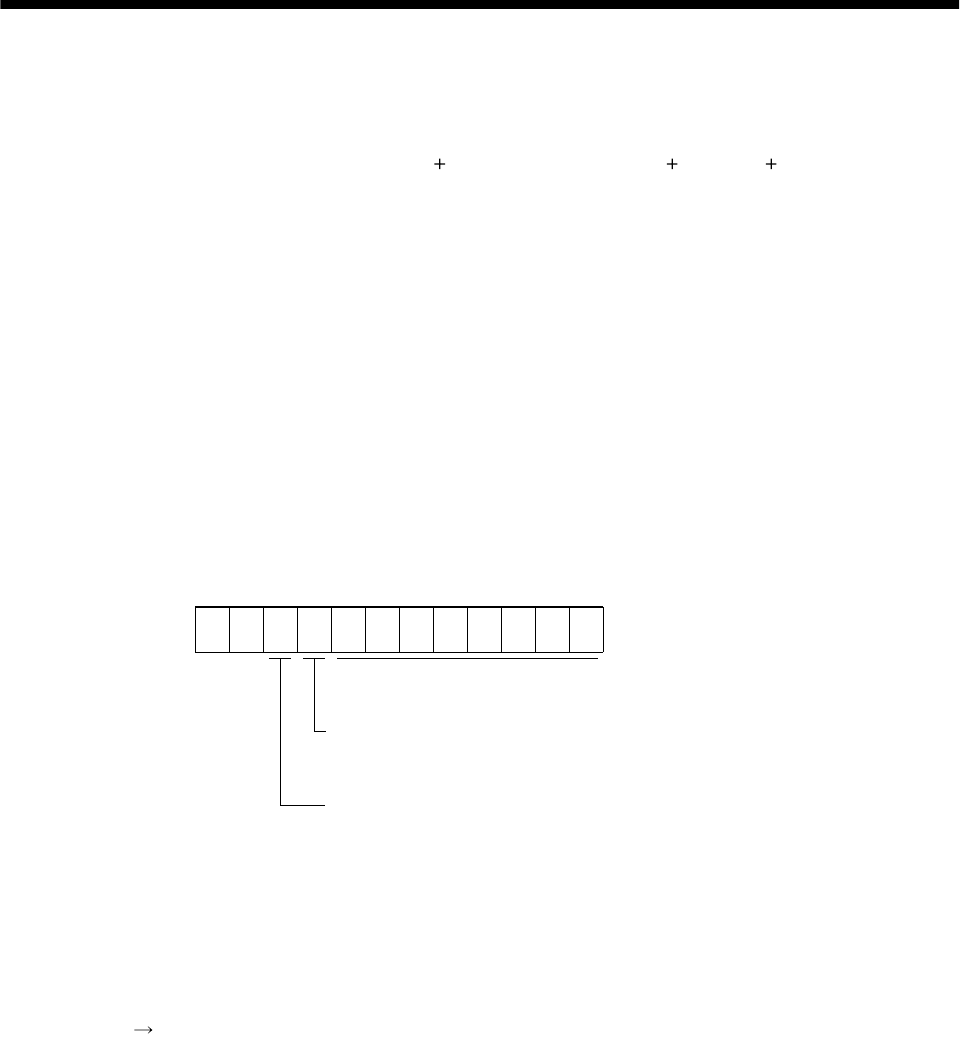
14 - 14
14. COMMUNICATION FUNCTIONS
14.12 Detailed explanations of commands
14.12.1 Data processing
When the master station transmits a command data No. or a command data No. data to a slave
station, the servo amplifier returns a reply or data according to the purpose.
When numerical values are represented in these send data and receive data, they are represented in
decimal, hexadecimal, etc.
Therefore, data must be processed according to the application.
Since whether data must be processed or not and how to process data depend on the monitoring,
parameters, etc., follow the detailed explanation of the corresponding command.
The following methods are how to process send and receive data when reading and writing data.
(1) Processing the read data
When the display type is 0, the eight-character data is converted from hexadecimal to decimal and a
decimal point is placed according to the decimal point position information.
When the display type is 1, the eight-character data is used unchanged.
The following example indicates how to process the receive data "003000000929" given to show.
The receive data is as follows.
00
Data 32-bit length (hexadecimal representation)
(Data conversion is required as indicated in the display type
)
Display type
0: Data must be converted into decimal.
1: Data is used unchanged in hexadecimal.
Decimal point position
0: No decimal point
1: First least significant digit (normally not used)
2: Second least significant digit
3: Third least significant digit
4: Forth least significant digit
5: Fifth least significant digit
6: Sixth least significant digit
3000000929
Since the display type is "0" in this case, the hexadecimal data is converted into decimal.
00000929H 2345
As the decimal point position is "3", a decimal point is placed in the third least significant digit.
Hence, "23.45" is displayed.
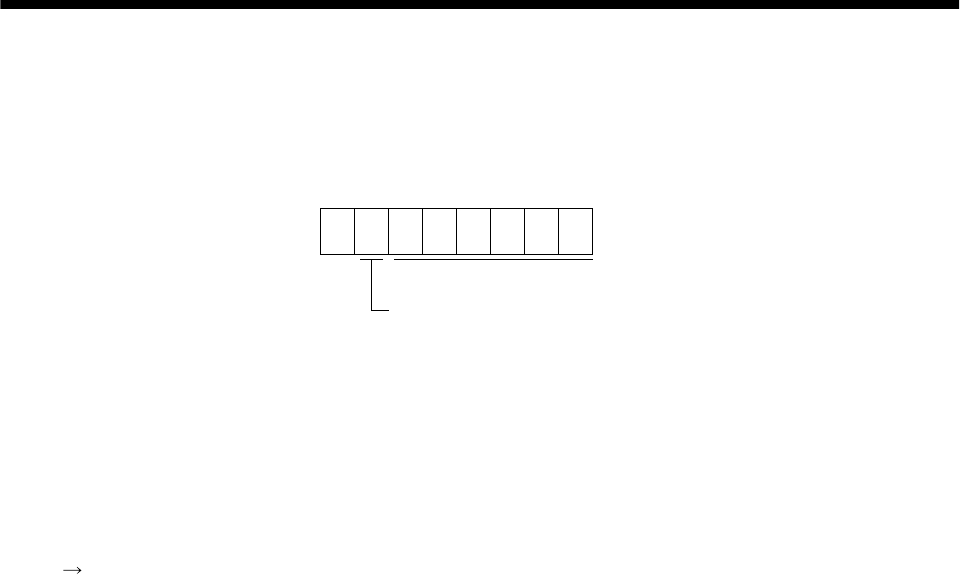
14 - 15
14. COMMUNICATION FUNCTIONS
(2) Writing the processed data
When the data to be written is handled as decimal, the decimal point position must be specified. If it is
not specified, the data cannot be written. When the data is handled as hexadecimal, specify "0" as the
decimal point position.
The data to be sent is the following value.
0
Data is transferred in hexadecimal.
Decimal point position
0: No decimal point
1: First least significant digit
2: Second least significant digit
3: Third least significant digit
4: Forth least significant digit
5: Fifth least significant digit
By way of example, here is described how to process the set data when a value of "15.5" is sent.
Since the decimal point position is the second digit, the decimal point position data is "2".
As the data to be sent is hexadecimal, the decimal data is converted into hexadecimal.
155 9B
Hence, "0200009B" is transmitted.
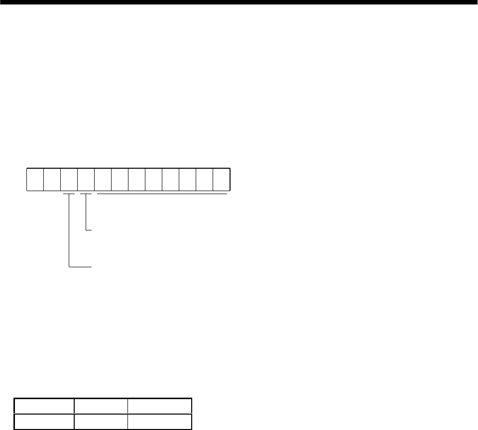
14 - 16
14. COMMUNICATION FUNCTIONS
14.12.2 Status display
(1) Status display data read
When the master station transmits the data No. (refer to the following table for assignment) to the
slave station, the slave station sends back the data value and data processing information.
1) Transmission
Transmit command [0][1] and the data No. corresponding to the status display item to be read.
Refer to Section 14.11.1.
2) Reply
The slave station sends back the status display data requested.
00
Data 32 bits long (represented in hexadecimal)
(Data conversion into display type is required)
Display type
0: Used unchanged in hexadecimal
1: Conversion into decimal required
Decimal point position
0: No decimal point
1: Lower first digit (usually not used)
2: Lower second digit
3: Lower third digit
4: Lower fourth digit
5: Lower fifth digit
6: Lower sixth di
g
it
(2) Status display data clear
The cumulative feedback pulse data of the status display is cleared. Send this command immediately
after reading the status display item. The data of the status display item transmitted is cleared to zero.
Command Data No. Data
[8][1] [0][0] 1EA5
For example, after sending command [0][1] and data No. [8][0] and receiving the status display data,
send command [8][1], data No. [0][0] and data [1EA5] to clear the cumulative feedback pulse value to
zero.
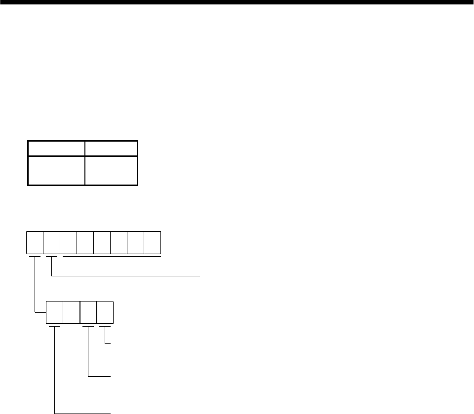
14 - 17
14. COMMUNICATION FUNCTIONS
14.12.3 Parameter
(1) Parameter read
Read the parameter setting.
1) Transmission
Transmit command [0][5] and the data No. corresponding to the parameter No.
The data No. is expressed in hexadecimal equivalent of the data No. value corresponds to the
parameter number.
Command Data No.
[0][5] [0][0] to
[5][4]
2) Reply
The slave station sends back the data and processing information of the requested parameter No.
Data is transferred in hexadecimal.
Decimal point position
0: No decimal point
1: Lower first digit
2: Lower second digit
3: Lower third digit
4: Lower fourth digit
5: Lower fifth digit
Display type
0: Used unchanged in hexadecimal
1: Conversion into decimal required
Parameter write type
0: Valid after write
1: Valid when power is switched on again after write
Read enable/disable
0: Read enable
1: Read disable
0
Enable/disable information changes according to the setting of parameter No.19 "parameter
write inhibit". When the enable/disable setting is read disable, ignore the parameter data part
and process it as unreadable.
14 - 18
14. COMMUNICATION FUNCTIONS
(2) Parameter write
POINT
The number of write times to the EEP-ROM is limited to 100,000.
Write the parameter setting.
Write the value within the setting range. Refer to Section 5.1 for the setting range.
Transmit command [8][4], the data No., and the set data.
The data No. is expressed in hexadecimal. The decimal equivalent of the data No. value corresponds to
the parameter number.
When the data to be written is handled as decimal, the decimal point position must be specified. If it
is not specified, data cannot be written. When the data is handled as hexadecimal, specify 0 as the
decimal point position.
Write the data after making sure that it is within the upper/lower limit value range given in Section
5.1.2. Read the parameter data to be written, confirm the decimal point position, and create
transmission data to prevent error occurrence. On completion of write, read the same parameter
data to verify that data has been written correctly.
Command Data No. Set data
[8][4] [0][0] to
[5][4] See below.
Data is transferred in hexadecimal.
Decimal point position
0: No decimal point
1: Lower first digit
2: Lower second digit
3: Lower third digit
4: Lower forth digit
5: Lower fifth digit
Write mode
0: Write to EEP-ROM
3: Write to RAM
When the parameter data is changed frequently through communication,
set "3" to the write mode to change only the RAM data in the servo amplifier.
When changing data frequently (once or more within one hour),
do not write it to the EEP-ROM.
14 - 19
14. COMMUNICATION FUNCTIONS
14.12.4 External I/O pin statuses (DIO diagnosis)
(1) External input pin status read
Read the ON/OFF statuses of the external input pins.
(a) Transmission
Transmit command [1][2] and data No. [4][0].
Command Data No.
[1][2] [4][0]
(b) Reply
The ON/OFF statuses of the input pins are sent back.
b31 b0
0: OFF
1: ON
b1
Command of each bit is transmitted to the master
station as hexadecimal data.
bit External input pin bit External input pin bit External input pin bit External input pin
0 CN1B-16 8 CN1B-9 16 24
1CN1B-17 9 17 25
2 CN1B-15 10 18 26
3CN1B-5111927
4 CN1B-14 12 20 28
5CN1A-8132129
6CN1B-7142230
7CN1B-8152331
(2) External output pin status read
Read the ON/OFF statuses of the external output pins.
(a) Transmission
Transmit command [1][2] and data No. [C][0].
Command Data No.
[1][2] [C][0]
(b) Reply
The slave station sends back the ON/OFF statuses of the output pins.
b31 b0
0: OFF
1: ON
b1
Command of each bit is transmitted to the master
station as hexadecimal data.
bit External output pin bit External output pin bit External output pin bit External output pin
0CN1A-19 8 16 24
1CN1A-18 9 17 25
2 CN1B-19 10 18 26
3CN1B-6111927
4CN1B-4122028
5 CN1B-18 13 21 29
6 CN1A-14 14 22 30
7 152331

14 - 20
14. COMMUNICATION FUNCTIONS
14.12.5 Disable/enable of external I/O signals (DIO)
Inputs can be disabled independently of the external I/O signal ON/OFF. When inputs are disabled, the
input signals are recognized as follows. Among the external input signals, EMG, LSP and LSN cannot be
disabled.
Signal Status
External input signals (DI) OFF
External analog input signals 0V
Pulse train inputs None
(1) Disabling/enabling the external input signals (DI), external analog input signals and pulse train
inputs with the exception of EMG, LSP and LSN.
Transmit the following communication commands:
(a) Disable
Command Data No. Data
[9][0] [0][0] 1EA5
(b) Enable
Command Data No. Data
[9][0] [1][0] 1EA5
(2) Disabling/enabling the external output signals (DO)
Transmit the following communication commands:
(a) Disable
Command Data No. Data
[9][0] [0][3] 1EA5
(b) Enable
Command Data No. Data
[9][0] [1][3] 1EA5
14 - 21
14. COMMUNICATION FUNCTIONS
14.12.6 External input signal ON/OFF (test operation)
Each input signal can be turned on/off for test operation. Turn off the external input signals.
Send command [9] [2], data No. [0] [0] and data.
Command Data No. Set data
[9][2] [0][0] See below
b31 b0
0: OFF
1: ON
b1
Command of each bit is transmitted to the slave
station as hexadecimal data.
bit Signal abbreviation bit Signal abbreviation bit Signal abbreviation bit Signal abbreviation
0SON 8 16 24
1LSP 9 17 25
2 LSN 10 18 26
3 TL 11 ST1 19 27
4 12 ST2 20 28
5PC132129
6 RES 14 22 30
7CR152331

14 - 22
14. COMMUNICATION FUNCTIONS
14.12.7 Test operation mode
(1) Instructions for test operation mode
The test operation mode must be executed in the following procedure. If communication is interrupted
for longer than 0.5s during test operation, the servo amplifier causes the motor to be decelerated to a
stop and servo-locked. To prevent this, continue communication without a break, e.g. monitor the
status display.
(a) Execution of test operation
1) Turn off all external input signals.
2) Disable the external input signals.
Command Data No. Data
[9][0] [0][0] 1EA5
3) Choose the test operation mode.
Command Data No. Transmission data Selection of test operation mode
[8][B] [0][0] 0000 Test operation mode cancel
[8][B] [0][0] 0001 Jog operation
[8][B] [0][0] 0002 Positioning operation
[8][B] [0][0] 0003 Motor-less operation
[8][B] [0][0] 0004 DO forced output
4) Set the data needed for test operation.
5) Start.
6) Continue communication using the status display or other command.
(b) Termination of test operation
To terminate the test operation mode, complete the corresponding operation and:
1) Clear the test operation acceleration/deceleration time constant.
Command Data No. Data
[A][0] [1][2] 1EA5
2) Cancel the test operation mode.
Command Data No. Data
[8][B] [0][0] 0000
3) Enable the disabled external input signals.
Command Data No. Data
[9][0] [1][0] 1EA5

14 - 23
14. COMMUNICATION FUNCTIONS
(2) Jog operation
Transmit the following communication commands:
(a) Setting of jog operation data
Item Command Data No. Data
Speed [A][0] [1][0] Write the speed [r/min] in hexadecimal.
Acceleration/decelerati
on time constant [A][0] [1][1] Write the acceleration/deceleration time constant
[ms] in hexadecimal.
(b) Start
Turn on the input devices SON LSP LSN by using command [9][2] data No. [0][0].
Item Command Data No. Data
Forward rotation start [9][2] [0][0] 00000807: Turns on SON LSP LSN ST1.
Reverse rotation start [9][2] [0][0] 00001007: Turns on SON LSP LSN ST2.
Stop [9][2] [0][0] 00000007: Turns on SON LSP and LSN.
(3) Positioning operation
Transmit the following communication commands:
(a) Setting of positioning operation data
Item Command Data No. Data
Speed [A][0] [1][0] Write the speed [r/min] in hexadecimal.
Acceleration/decelerat
ion time constant [A][0] [1][1] Write the acceleration/deceleration time constant
[ms] in hexadecimal.
Moving distance [A][0] [1][3] Write the moving distance [pulse] in
hexadecimal.
(b) Input of servo-on stroke end
Turn on the input devices SON LSP and LSN by using command [9][2] data No. [0][0].
Item Command Data No. Data
Servo-on [9][2] [0][0] 00000001: Turns on SON.
Servo OFF
Stroke end ON [9][2] [0][0] 00000006: Turns off SON and turns on LSP
LSN.
Servo-on
Stroke end ON [9][2] [0][0] 00000007: Turns on SON LSP LSN.
(c) Start of positioning operation
Transmit the speed and acceleration/deceleration time constant, turn on the servo-on (SON) and
forward/reverse rotation stroke end (LSP LSN), and then send the moving distance to start
positioning operation. After that, positioning operation will start every time the moving distance is
transmitted. To start opposite rotation, send the moving distance of a negative value.
When the servo-on (SON) and forward/reverse rotation stroke end (LSP LSN) are off, the
transmission of the moving distance is invalid. Therefore, positioning operation will not start if the
servo-on (SON) and forward/reverse rotation stroke end (LSP LSN) are turned on after the setting
of the moving distance.
(d) Temporary stop
A temporary stop can be made during positioning operation.
Command Data No. Data
[A][0] [1][5] 1EA5
Retransmit the same communication commands as at the start time to resume operation.
To stop positioning operation after a temporary stop, retransmit the temporary stop communication
command. The remaining moving distance is then cleared.
14 - 24
14. COMMUNICATION FUNCTIONS
14.12.8 Output signal pin ON/OFF output signal (DO) forced output
In the test operation mode, the output signal pins can be turned on/off independently of the servo status.
Using command [9][0], disable the output signals in advance.
(1) Choosing DO forced output in test operation mode
Transmit command [8][B] data No. [0][0] data "0004" to choose DO forced output.
00
Selection of test operation mode
4: DO forced output (output signal forced output)
04
(2) External output signal ON/OFF
Transmit the following communication commands:
Command Data No. Setting data
[9][2] [A][0] See below.
Command of each bit is sent to the slave station in hexadecimal.
b31 b0
0: OFF
1: ON
b1
bit External output pin bit External output pin bit External output pin bit External output pin
0CN1A-19 8 16 24
1CN1A-18 9 17 25
2 CN1B-19 10 18 26
3CN1B-6111927
4CN1B-4122028
5 CN1B-18 13 21 29
6 CN1A-14 14 22 30
7 152331
14 - 25
14. COMMUNICATION FUNCTIONS
14.12.9 Alarm history
(1) Alarm No. read
Read the alarm No. which occurred in the past. The alarm numbers and occurrence times of No. 0 (last
alarm) to No. 5 (sixth alarm in the past) are read.
(a) Transmission
Send command [3][3] and data No. [1][0] to [1][5]. Refer to Section 14.11.1.
(b) Reply
The alarm No. corresponding to the data No. is provided.
00
Alarm No. is transferred in decimal.
For example, “0032” means AL.32 and “00FF” means AL._ (no alarm).
(2) Alarm occurrence time read
Read the occurrence time of alarm which occurred in the past.
The alarm occurrence time corresponding to the data No. is provided in terms of the total time
beginning with operation start, with the minute unit omitted.
(a) Transmission
Send command [3][3] and data No. [2][0] to [2][5].
Refer to Section 14.11.1.
(b) Reply
The alarm occurrence time is transferred in decimal.
Hexadecimal must be converted into decimal.
For example, data “01F5” means that the alarm occurred in 501 hours after start of operation.
(3) Alarm history clear
Erase the alarm history.
Send command [8][2] and data No. [2][0].
Command Data No. Data
[8][2] [2][0] 1EA5
14 - 26
14. COMMUNICATION FUNCTIONS
14.12.10 Current alarm
(1) Current alarm read
Read the alarm No. which is occurring currently.
(a) Transmission
Send command [0][2] and data No. [0][0].
Command Data No.
[0][2] [0][0]
(b) Reply
The slave station sends back the alarm currently occurring.
00
Alarm No. is transferred in decimal.
For example, “0032” means AL.32 and “00FF” means AL._ (no alarm).
(2) Read of the status display at alarm occurrence
Read the status display data at alarm occurrence. When the data No. corresponding to the status
display item is transmitted, the data value and data processing information are sent back.
(a) Transmission
Send command [3][5] and any of data No. [8][0] to [8][E] corresponding to the status display item to
be read. Refer to Section 14.11.1.
(b) Reply
The slave station sends back the requested status display data at alarm occurrence.
00
Data 32 bits long (represented in hexadecimal)
(Data conversion into display type is required)
Display type
0: Conversion into decimal required
1: Used unchanged in hexadecimal
Decimal point position
0: No decimal point
1: Lower first digit (usually not used)
2: Lower second digit
3: Lower third digit
4: Lower fourth digit
5: Lower fifth digit
6: Lower sixth digit
(3) Current alarm clear
As by the entry of the reset (RES), reset the servo amplifier alarm to make the servo amplifier ready to
operate. After removing the cause of the alarm, reset the alarm with no command entered.
Command Data No. Data
[8][2] [0][0] 1EA5

14 - 27
14. COMMUNICATION FUNCTIONS
14.12.11 Other commands
(1) Servo motor end pulse unit absolute position
Read the absolute position in the servo motor end pulse unit.
Note that overflow will occur in the position of 16384 or more revolutions from the home position.
(a) Transmission
Send command [0][2] and data No. [9][0].
Command Data No.
[0][2] [9][0]
(b) Reply
The slave station sends back the requested servo motor end pulses.
Absolute value is sent back in hexadecimal in
the servo motor end pulse unit.
(Must be converted into decimal)
For example, data "000186A0" is 100000 [pulse] in the motor end pulse unit.
(2) Command unit absolute position
Read the absolute position in the command unit.
(a) Transmission
Send command [0][2] and data No. [9][1].
Command Data No.
[0][2] [9][1]
(b) Reply
The slave station sends back the requested command pulses.
Absolute value is sent back in hexadecimal in the
command unit.
(Must be converted into decimal)
For example, data "000186A0" is 100000 [pulse] in the command unit.
(3) Software version
Reads the software version of the servo amplifier.
(a) Transmission
Send command [0][2] and data No.[7][0].
Command Data No.
[0][2] [7][0]
(b) Reply
The slave station returns the software version requested.
Software version (15 digits)
Space

14 - 28
14. COMMUNICATION FUNCTIONS
MEMO
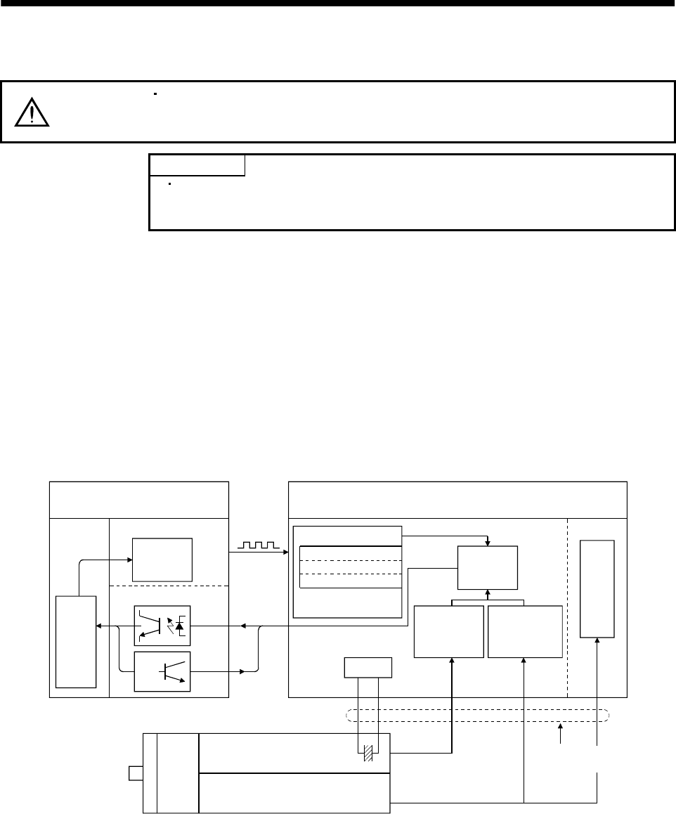
15 - 1
15. ABSOLUTE POSITION DETECTION SYSTEM
15. ABSOLUTE POSITION DETECTION SYSTEM
CAUTION
If an absolute position erase alarm (AL.25) or an absoluto position counter marning
(AL.E3) has occurred, always perform home position setting again. Not doing so
can cause runaway.
POINT
When configuring an absolute position detection system using the QD75P/D
PLC, refer to the Type QD75P/QD75D Positioning Module User's Manual
QD75P1/QD75P2/QD75P4, QD75D1/QD75D2/QD75D4 (SH (NA) 080058).
15.1 Outline
15.1.1 Features
For normal operation, as shown below, the encoder consists of a detector designed to detect a position
within one revolution and a cumulative revolution counter designed to detect the number of revolutions.
The absolute position detection system always detects the absolute position of the machine and keeps it
battery-backed, independently of whether the general-purpose programming controller power is on or off.
Therefore, once the home position is defined at the time of machine installation, home position return is
not needed when power is switched on thereafter.
If a power failure or a fault occurs, restoration is easy.
Also, the absolute position data, which is battery-backed by the super capacitor in the encoder, can be
retained within the specified period (cumulative revolution counter value retaining time) if the cable is
unplugged or broken.
LSO
1XO
MR-BAT
CPU
General purpose programmable
controller Servo amplifier
Pulse train
(command)
Changing the
current position
data
Positioning module
I/O module
Current
position
data
Input
Output
Home position data
EEPROM memory
Backed up in the
case of power failure
Current
position
data
Detecting the
number of
revolutions
LS 1X
Detecting the
position within
one revolution
Position control
Speed control
Servo motor
1 pulse/rev Accumulative
revolution counter Super capacitor
Within-one-revolution counter
(
Position detector
)
High speed serial
communication
Battery
15.1.2 Restrictions
The absolute position detection system cannot be configured under the following conditions. Test
operation cannot be performed in the absolute position detection system, either. To perform test
operation, choose incremental in parameter No.1.
(1) Speed control mode, torque control mode.
(2) Control switch-over mode (position/speed, speed/torque, torque/position).
(3) Stroke-less coordinate system, e.g. rotary shaft, infinitely long positioning.
(4) Changing of electronic gear after home position setting.
(5) Use of alarm code output.
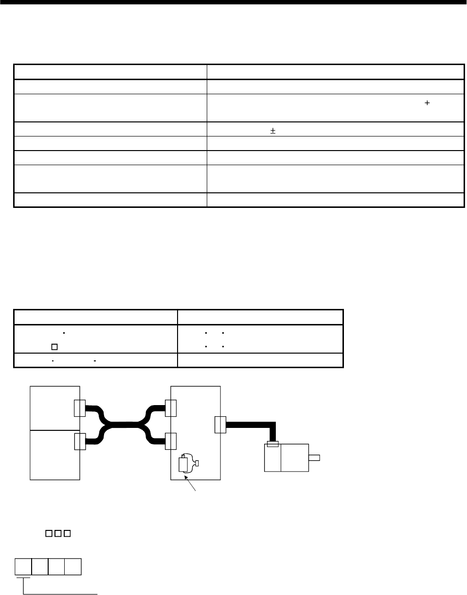
15 - 2
15. ABSOLUTE POSITION DETECTION SYSTEM
15.2 Specifications
(1) Specification list
Item Description
System Electronic battery backup system
Battery 1 piece of lithium battery ( primary battery, nominal 3.6V)
Type: MR-BAT or A6BAT
Maximum revolution range Home position 32767 rev.
(Note 1) Maximum speed at power failure 500r/min
(Note 2) Battery backup time Approx. 10,000 hours (battery life with power off)
(Note 3) Data holding time during battery
replacement 2 hours at delivery, 1 hour in 5 years after delivery
Battery storage period 5 years from date of manufacture
Note 1. Maximum speed available when the shaft is rotated by external force at the time of power failure or the like.
2. Time to hold data by a battery with power off. It is recommended to replace the battery in three years independently of whether
power is kept on or off.
3. Period during which data can be held by the super capacitor in the encoder after power-off, with the battery voltage low or the
battery removed, or during which data can be held with the encoder cable disconnected.
Battery replacement should be finished within this period.
(2) Configuration
Positioning module I/O module
A1SD71S2 A1SD71S7
A1SD75 AX40 41 42
AY40 41 42
FX-1PG FX-1GM FX-10GM FX2-32MT
CN1A
CN1B
CON1
Servo motor
CN2
A1SD75 etc.
I/O
Programmable controller Servo amplifier
Battery (MR-BAT)
(3) Parameter setting
Set " 1 " in parameter No.1 to make the absolute position detection system valid.
1
Selection of absolute position detection system
0: Incremental system
1: Absolute position detection system
Parameter No. 1
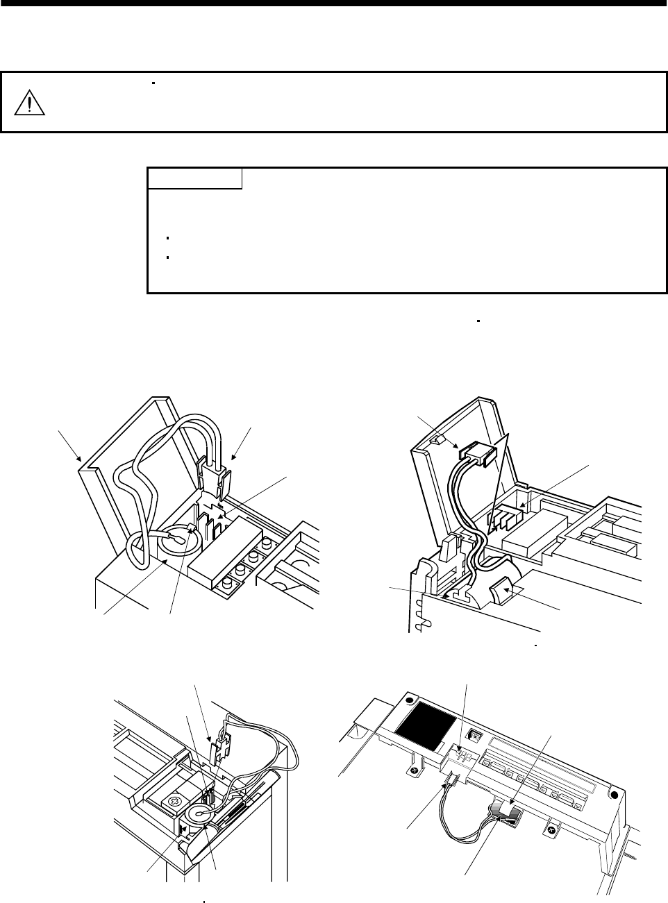
15 - 3
15. ABSOLUTE POSITION DETECTION SYSTEM
15.3 Battery installation procedure
WARNING Before starting battery installation procedure, make sure that the charge lamp is off
more than 15 minutes after power-off. Then, confirm that the voltage is safe in the
tester or the like. Otherwise, you may get an electric shock.
POINT
The internal circuits of the servo amplifier may be damaged by static electricity.
Always take the following precautions:
Ground human body and work bench.
Do not touch the conductive areas, such as connector pins and electrical
parts, directly by hand.
(1) Open the operation window. (When the model used is the MR-J2S-200A MR-J2S-350A or more, also
remove the front cover.)
(2) Install the battery in the battery holder.
(3) Install the battery connector into CON1 until it clicks.
Battery connector
Battery
Operation window
CON1
Battery holder
CON1
Battery connector
Battery
Battery holder
For MR-J2S-100A or less
Battery connector
CON1
Battery holder Battery
For MR-J2S-500A MR-J2S-700A
For MR-J2S-200A MR-J2S-350A
For MR-J2S-11KA or more
Battery holder
CON1
Battery
Battery connector
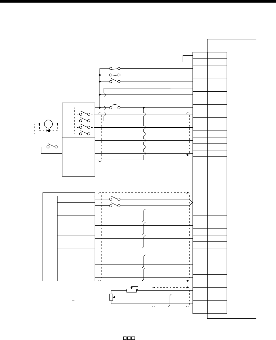
15 - 4
15. ABSOLUTE POSITION DETECTION SYSTEM
15.4 Standard connection diagram
CR
SG
RA2
CN1B-3
CN1B-13COM
CN1B-16LSP
CN1B-17LSN
CN1B-7TL
CN1B-14RES
CN1B-10SG
CN1B-5SON
CN1B-15EMG
CN1B-8ABSM
CN1B-9ABSR
CN1B-4DO1
CN1B-19ZSP
CN1B-6TLC
VDD
SG CN1A-10
CN1B-3VDD
CN1A-19RD
CN1A-4P15R
CN1A-14OP
CN1A-8
CN1A-20
CN1A-3PP
CN1A-13PG
CN1A-2NP
CN1A-12NG
CN1B-11P15R
CN1B-12TLA
CN1B-1LG
PlateSD
Servo amplifier
I/O module
Input
Output
Reset
Reset (Note 3)
EMG (Note 1)
Positioning
module
(Note 2) Stroke end in forward rotation
Stroke end in reverse rotation
External torque control
Electromagnetic
brake output
Near-zero point signal
Stop signal
Power supply (24V)
Ready
Zero-point
signal
Clear
Command
pulses
(for differential
line driver type)
Dog
Stop
Emergency stop
Servo-on
ABS transmission
mode
ABS request
ABS bit 0
ABS bit 1
Send data ready
Torque limit
10V/max.torque
Upper limit setting
Note 1. Always install the emergency stop switch.
2. For operation, always turn on forward rotation stroke end (LSP)/reverse rotation stroke end (LSN).
3. When using the torque limit signal (TL), set " 4" in parameter No.46 to assign TL to pin CN1B-7.

15 - 5
15. ABSOLUTE POSITION DETECTION SYSTEM
15.5 Signal explanation
When the absolute position data is transferred, the signals of connector CN1 change as described in this
section. They return to the previous status on completion of data transfer. The other signals are as
described in Section 3.3.2.
For the I/O interfaces (symbols in the I/O Category column in the table), refer to Section 3.6.
Signal name Code Pin No. Function/Application I/O
category
Control
mode
ABS transfer
mode ABSM (Note)
CN1B-8
While ABSM is on, the servo amplifier is in the ABS
transfer mode, and the functions of ZSP, TLC, and D01
are as indicated in this table. DI-1
ABS request ABSR (Note)
CN1B-9 Turn on ABSR to request the ABS data in the ABS
transfer mode. DI-1
ABS bit 0 D01 CN1B-4
Indicates the lower bit of the ABS data (2 bits) which is
sent from the servo to the programmable controller in
the ABS transfer mode.
If there is a signal, D01 turns on.
DO-1
ABS bit 1 ZSP CN1B-19
Indicates the upper bit of the ABS data (2 bits) which is
sent from the servo to the programmable controller in
the ABS transfer mode.
If there is a signal, ZSP turns on.
DO-1
Send data ready TLC CN1B-6 Indicates that the data to be sent is being prepared in
the ABS transfer mode. At the completion of the ready
state, TLC turns on. DO-1
Home position
setting CR CN1A-8 When CR is turned on, the position control counter is
cleared and the home position data is stored into the
non-volatile memory (backup memory). DI-1
P
(Position
control)
Note. When "Used in absolute position detection system" is selected in parameter No. 1, pin CN1B-8 acts as the ABS transfer mode
(ABSM) and pin CN1B-9 as the ABS request (ABSR). They do not return to the original signals if data transfer ends.

15 - 6
15. ABSOLUTE POSITION DETECTION SYSTEM
15.6 Startup procedure
(1) Battery installation.
Refer to Section 15.3 installation of absolute position backup battery.
(2) Parameter setting
Set "1 "in parameter No. 1 of the servo amplifier and switch power off, then on.
(3) Resetting of absolute position erase (AL.25)
After connecting the encoder cable, the absolute position erase (AL.25) occurs at first power-on. Leave
the alarm as it is for a few minutes, then switch power off, then on to reset the alarm.
(4) Confirmation of absolute position data transfer
When the servo-on (SON) is turned on, the absolute position data is transferred to the programmable
controller. When the ABS data is transferred properly:
(a) The ready output (RD) turns on.
(b) The programmable controller/ABS data ready contact (M3 for A1SD71, M99 for 1PG) turns on.
(c) The MR Configurator (servo configuration software) ABS data display window (refer to Section
15.9) and programmable controller side ABS data registers (D3, D4 for A1SD71, D106, D107 for
1PG) show the same value (at the home position address of 0).
If any warning such as ABS time-out warning (AL.E5) or programmable controller side transfer
error occurs, refer to Section 15.10 or Chapter 10 and take corrective action.
(5) Home position setting
The home position must be set if:
(a) System setup is performed;
(b) The servo amplifier has been changed;
(c) The servo motor has been changed; or
(d) The absolute position erase (AL.25) occurred.
In the absolute position system, the absolute position coordinates are made up by making home
position setting at the time of system setup.
The motor shaft may misoperate if positioning operation is performed without home position setting.
Always make home position setting before starting operation.
For the home position setting method and types, refer to Section 15.7.3.
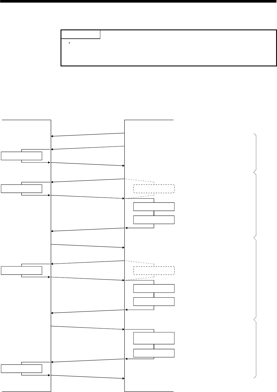
15 - 7
15. ABSOLUTE POSITION DETECTION SYSTEM
15.7 Absolute position data transfer protocol
POINT
After switching on the ABS transfer mode (ABSM), turn on the servo-on
signal (SON). When the ABS transfer mode is off, turning on the servo-on
signal (SON) does not switch on the base circuit.
15.7.1 Data transfer procedure
Each time the servo-on (SON) is turned ON (when the power is switched ON for example), the
programmable controller reads the position data (present position) of the servo amplifier.
Time-out monitoring is performed by the programmable controller.
Servo-on (SON) ON
Servo amplifier Programmable controller
ABS transfer mode ON
Send data ready ON
ABS request ON
Send data ready OFF
ABS request OFF
Send data ready ON
ABS request ON
Send data ready OFF
ABS request OFF
Send data ready ON
ABS transfer mode OFF
TLC (send data ready) OFF
DI0 allocation change
Transmission data set
Transmission data set
DI0 allocation change
Watch dog timer
Reading 2 bits
Shift and addition
Watch dog timer
Reading 2 bits
Shift and addition
Setting the current
position
Sum check
Every time the SON is
turned ON, the ABS transfer
mode signal is turned ON
to set the data to be
transmitted.
The data is read in units of
2 bits; the read data is written
to the lowest bits, and the
register is shifted right until
32-bit data is configured.
The data is read in units of
2 bits; the read data is written
to the lowest bits, and the
register is shifted right until
6-bit data is configured.
A sum check is executed
for the received 32-bit data.
After making sure that
there are no errors in the data,
the current position is set.
Start processing
Repeated to configure 32-bit data
Repeated to configure 6-bit dataEnd processing
16 times
3 times
<Current position data>
<Sum check data>
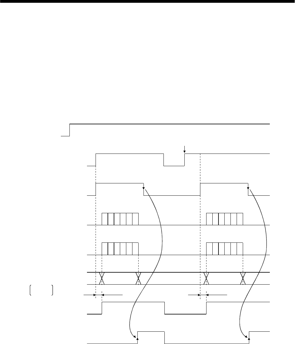
15 - 8
15. ABSOLUTE POSITION DETECTION SYSTEM
15.7.2 Transfer method
The sequence in which the base circuit is turned ON (servo-on) when it is in the OFF state due to the
servo-on (SON) going OFF, an emergency stop (EMG), or alarm (ALM), is explained below. In the
absolute position detection system, every time the servo-on (SON) is turned on, the ABS transfer mode
(ABSM) should always be turned on to read the current position in the servo amplifier to the controller.
The servo amplifier transmits to the controller the current position latched when the ABS transfer mode
(ABSM) switches from OFF to ON. At the same time, this data is set as a position command value inside
the servo amplifier. Unless the ABS transfer mode (ABSM) is turned ON, the base circuit cannot be
turned ON.
(1) At power-on
(a) Timing chart
OFF
ON
OFF
ON
OFF
ON
OFF
ON
OFF
ON
OFF
ON
OFF
ON
80[ms] 80[ms]
1)
2), 3)
Power
supply
Servo-on
(SON)
4)
ABS transfer mode
(ABSM)
ABS request
(ABSR)
Send data ready
(TLC)
Transmission
(ABS) data
Base circuit
Ready
(RD)
If SON is turned ON before ABSM is input
During transfer of ABS During transfer of ABS
(Note) (Note)
(Note) (Note)
(Note) (Note)
ABS data ABS data
Operation
enabled Operation
enabled
Note. For details, refer to (1) (b) in this section.
D01:bit1
ZSP:bit2

15 - 9
15. ABSOLUTE POSITION DETECTION SYSTEM
1) The ready (RD) is turned ON when the ABS transfer mode (ABSM) is turned OFF after
transmission of the ABS data.
While the ready (RD) is ON, the ABS transfer mode (ABSM) input is not accepted.
2) Even if the servo-on (SON) is turned ON before the ABS transfer mode (ABSM) is turned ON,
the base circuit is not turned ON until the ABS transfer mode (ABSM) is turned ON.
If a servo alarm has occurred, the ABS transfer mode (ABSM) is not received.
The ABS transfer mode (ABSM) allows data transmission even while a servo warning is
occurring.
3) If the ABS transfer mode (ABSM) is turned OFF during the ABS transfer mode, the ABS
transfer mode is interrupted and the ABS time-out warning (AL.E5) occurs.
4) The functions of output signals such as ZSP, TLC, D01, and INP change depending on the
ON/OFF state of the ABS transfer mode (ABSM).
Note that if the ABS transfer mode (ABSM) is turned ON for a purpose other than ABS data
transmission, the output signals will be assigned the functions of ABS data transmission.
Output signal
Symbol Pin No. ABS transfer mode (ABSM): OFF ABS transfer mode (ABSM): ON
(Note)
D01 CN1B-4 Positioning completion ABS data bit 0
ZSP CN1B-19 Zero speed ABS data bit 1
TLC CN1B-6 During torque limit control Send data ready
(Note)
INP CN1A-18 Positioning completion ABS data bit 0
Note. CN1B-4 and CN1A-18 output the same signals. (To enter the positioning completion signal into INPS of the A1SD75,
connect CN1A-18.)
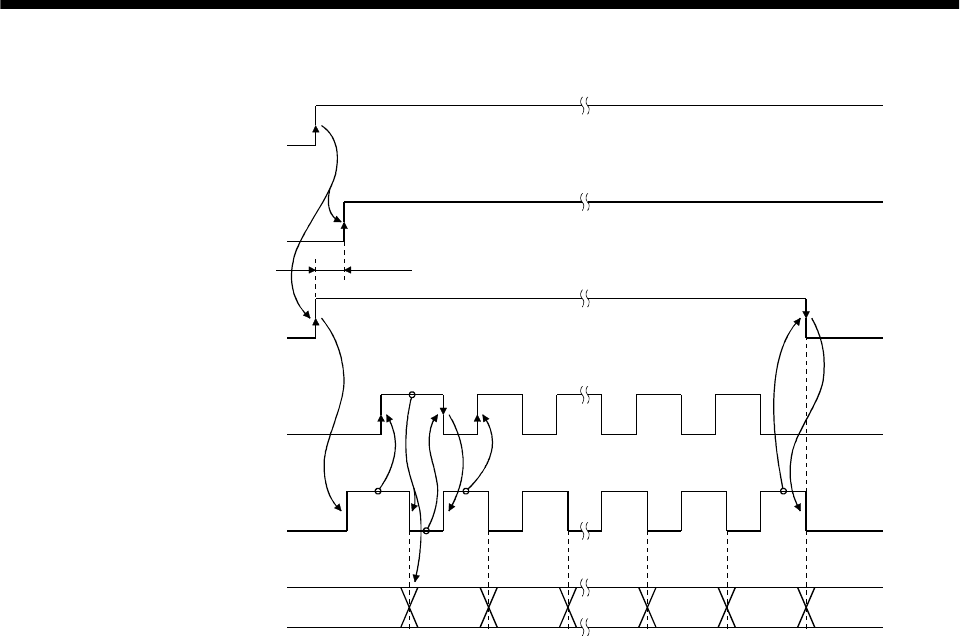
15 - 10
15. ABSOLUTE POSITION DETECTION SYSTEM
(b) Detailed description of absolute position data transfer
OFF
ON
OFF
ON
OFF
ON
OFF
ON
OFF
ON
3)
4)
5)
7)
(Note)
1)
2) 6)
Servo-on
(programmable
controller)
Servo-on
(SON)
ABS transfer mode
(ABSM)
ABS request
(ABSR)
Send data ready
(TLC)
Transmission (ABS) data
Note. If the servo-on (SON) is not turned ON within 1 second after the ABS transfer mode (ABSM) is turned ON,
an SON time-out warning (AL.EA) occurs. This warning, however, does not interrupt data transmission.
It is automaticall
y
cleared when the servo-on
(
SON
)
is turned ON.
During transfer of ABS
Lower
2 bits Check sum
Upper 2 bits
1) The programmable controller turns ON the ABS transfer mode (ABSM) and servo-on (SON) at
the leading edge of the internal servo-on (SON).
2) In response to the ABS transfer mode (ABSM), the servo detects and calculates the absolute
position and turns ON the send data ready (TLC) to notify the programmable controller that the
servo is ready for data transmission.
3) After acknowledging that the ready to send (TLC) has been turned ON, the programmable
controller turns ABS request (ABSR) ON.
4) In response to ABS request (ABSR), the servo outputs the lower 2 bits of the ABS data and the
ready to send (TLC) in the OFF state.
5) After acknowledging that the ready to send (TLC) has been turned OFF, which implies that 2
bits of the ABS data have been transmitted, the programmable controller reads the lower 2 bits
of the ABS data and then turns OFF the ABS request (ABSR).
6) The servo turns ON the ready to send (TLC) so that it can respond to the next request.
Steps 3) to 6) are repeated until 32-bit data and the 6-bit check sum have been transmitted.
7) After receiving of the check sum, the programmable controller turns the ABS transfer mode
(ABSM) OFF.
If the ABS transfer mode (ABSM) is turned OFF during data transmission, the ABS transfer
mode (ABSM) is interrupted.
15 - 11
15. ABSOLUTE POSITION DETECTION SYSTEM
(c) Checksum
The check sum is the code which is used by the programmable controller to check for errors in the
received ABS data. The 6-bit check sum is transmitted following the 32-bit ABS data.
At the programmable controller, calculate the sum of the received ABS data using the ladder
program and compare it with the check sum code sent from the servo.
The method of calculating the check sum is shown. Every time the programmable controller
receives 2 bits of ABS data, it adds the data to obtain the sum of the received data. The check sum
is 6-bit data.
Negative data is available for the FX-1PG and unavailable for the A1SD71.
Example: ABS data: 10 (FFFFFFF6H)
10b
01b
11b
11b
11b
11b
11b
11b
11b
11b
11b
11b
11b
11b
11b
b
11
101101b
10
FFFF FFF6
1111 1111 1111 0110
<Appendix>
Decimal
Hexadecimal
Binary
When the binary data of each 2bits of the
ABS data is added up, "10 1101 " is obtained.
b
Therefore, the check sum of " 10" (ABS data) is "2Db"
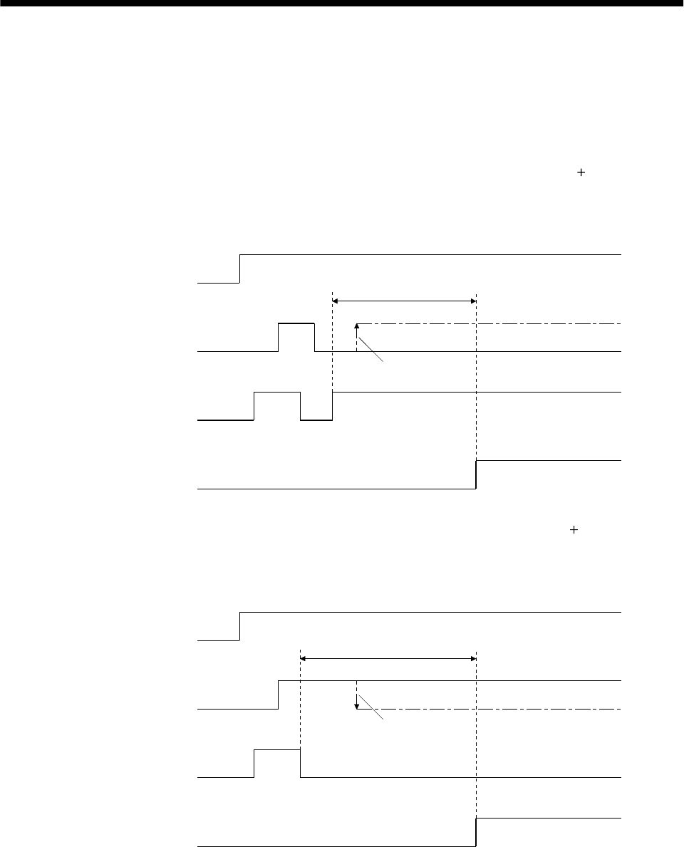
15 - 12
15. ABSOLUTE POSITION DETECTION SYSTEM
(2) Transmission error
(a) Time-out warning(AL.E5)
In the ABS transfer mode, the time-out processing shown below is executed at the servo. If a time-
out error occurs, an ABS time-out warning (AL.E5) is output.
The ABS time-out warning (AL.E5) is cleared when the ABS transfer mode (ABSM) changes from
OFF to ON.
1) ABS request OFF-time time-out check (applied to 32-bit ABS data in 2-bit units check sum)
If the ABS request signal is not turned ON by the programmable controller within 5s after the
send data ready (TLC) is turned ON, this is regarded as a transmission error and the ABS time-
out warning (AL.E5) is output.
OFF
ON
OFF
ON
OFF
ON
5s
A
BS transfer mode
A
BS request
Send data ready
A
L.E5 warning
Signal is not turned ON
No
Yes
2) ABS request ON-time time-out check (applied to 32-bit ABS data in 2-bit units check sum)
If the ABS request signal is not turned OFF by the programmable controller within 5s after the
send data ready (TLC) is turned OFF, this is regarded as the transmission error and the ABS
time-out warning (AL.E5) is output.
OFF
ON
OFF
ON
OFF
ON
5s
A
BS transfer mode
A
BS request
Send data ready
A
L.E5 warning
Signal is not turned OFF
No
Yes
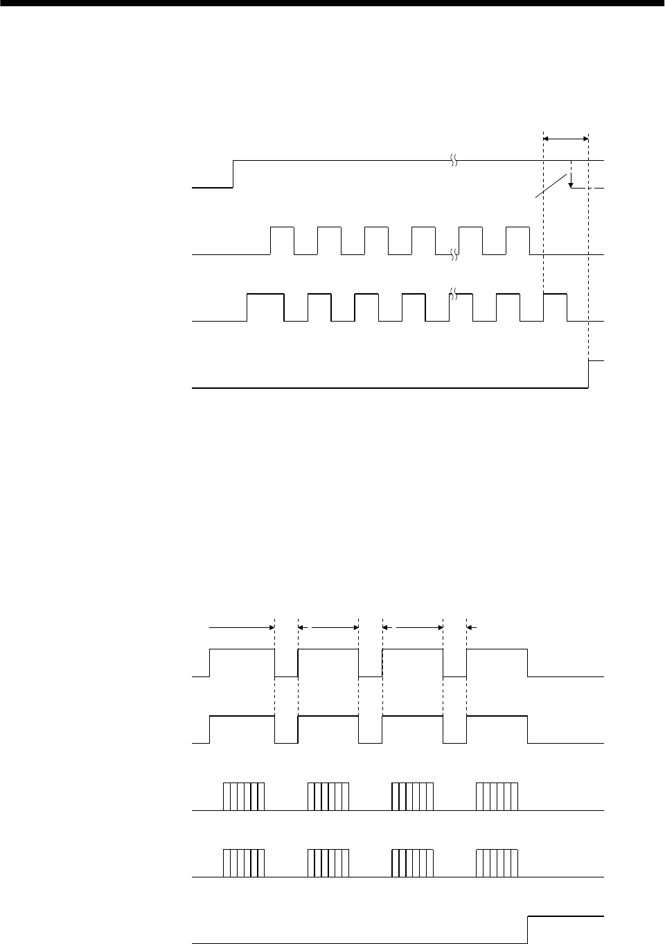
15 - 13
15. ABSOLUTE POSITION DETECTION SYSTEM
3) ABS transfer mode finish-time time-out check
If the ABS transfer mode (ABSR) is not turned OFF within 5s after the last ready to send signal
(19th signal for ABS data transmission) is turned ON, it is regarded as the transmission error
and the ABS time-out warning (AL.E5) is output.
OFF
ON
OFF
ON
OFF
ON
12341819
12341819
5s
A
BS transfer mode
A
BS request
Send data ready
A
L.E5 warning
Signal is not turned OFF
No
Yes
(b) Check sum error
If the check sum error occurs, the programmable controller should retry transmission of the ABS
data.
Using the ladder check program, turn OFF the ABS transfer mode (ABSM) and servo-on (SON)
once. Turn them ON again after an OFF time of longer than 20 ms.
If the ABS data transmission fails to end normally even after retry, regard this situation as an
ABS check sum error and execute error processing.
The start command should be interlocked with the ABS data ready signal to disable positioning
operation when an check sum error occurs.
OFF
ON
OFF
ON
OFF
ON
OFF
ON
Servo-on
ABS transfer mode
ABS request
Send data ready
ABS check sum error
20ms
or more
20ms
or more
20ms
or more
Retry 1Retry 2Retry 3
No
Yes
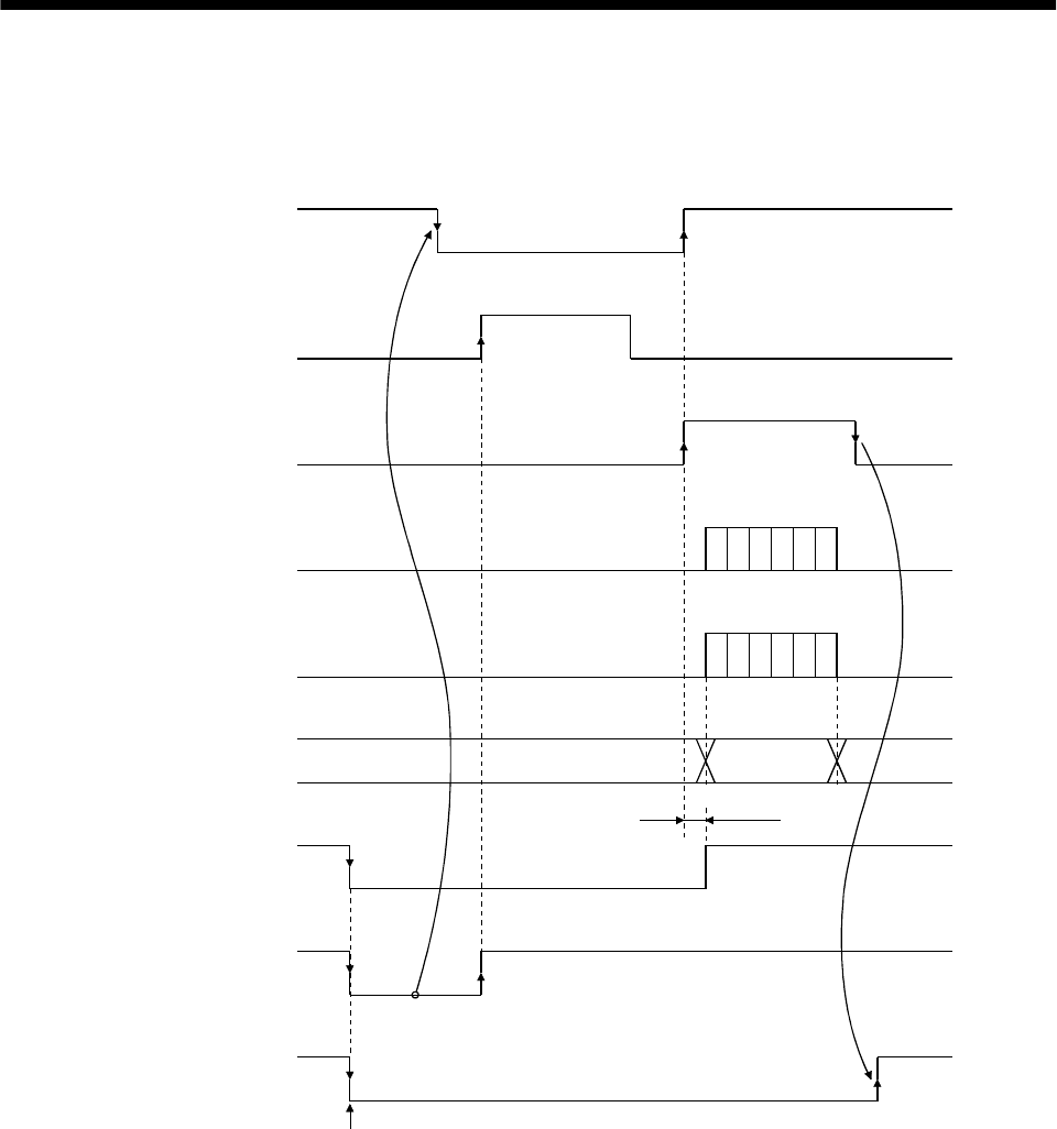
15 - 14
15. ABSOLUTE POSITION DETECTION SYSTEM
(3) At the time of alarm reset
If an alarm occurs, turn OFF the servo-on (SON) by detecting the alarm output (ALM).
If an alarm has occurred, the ABS transfer mode (ABSM) cannot be accepted.
In the reset state, the ABS transfer mode (ABSM) can be input.
OFF
ON
OFF
ON
OFF
ON
OFF
ON
OFF
ON
80[ms]
OFF
ON
OFF
ON
Servo-on
(SON)
Reset
(RES)
ABS transfer mode
(ABSM)
ABS request
(ABSR)
Send data ready
(TLC)
Transmission
(ABS) data
Base circuit
Alarm output
(ALM)
Ready
(RD)
Occurrence of alarm
During transfer of ABS
ABS data
Operation
enabled
OFF
ON
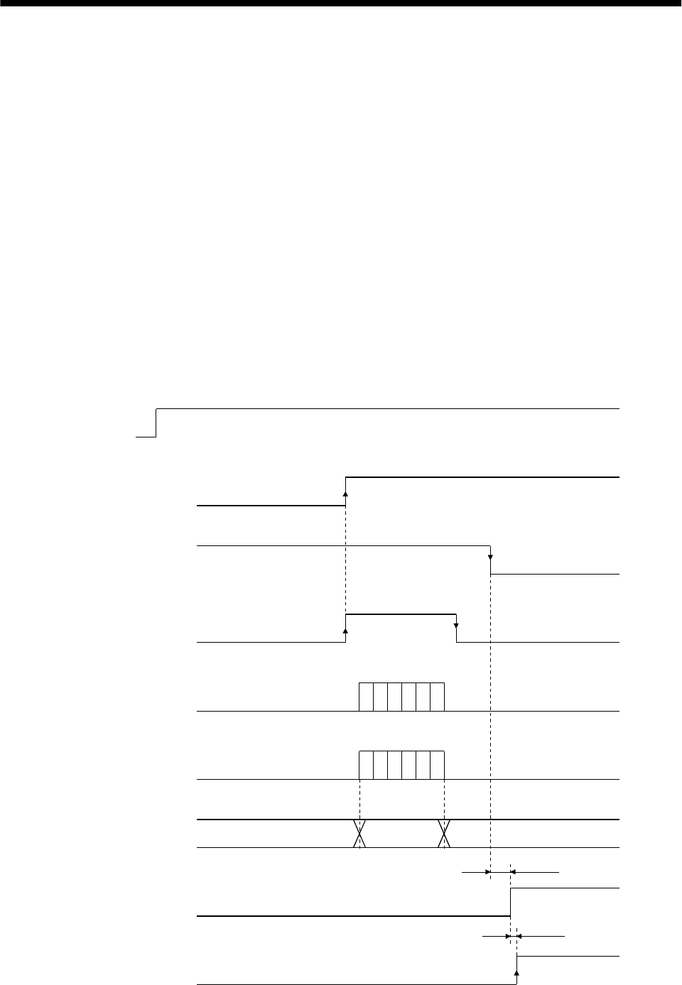
15 - 15
15. ABSOLUTE POSITION DETECTION SYSTEM
(4) At the time of emergency stop reset
(a) If the power is switched ON in the emergency stop state
The emergency stop state can be reset while the ABS data is being transferred.
If the emergency stop state is reset while the ABS data is transmitted, the base circuit is turned
ON 80[ms] after resetting. If the ABS transfer mode (ABSM) is OFF when the base circuit is
turned ON, the ready (RD) is turned ON 20[ms] after the turning ON of the base circuit. If the ABS
transfer mode (ABSM) is ON when the base circuit is turned ON, it is turned OFF and then the
ready (RD) is turned ON. The ABS data can be transmitted after the emergency stop state is reset.
The current position in the servo amplifier is updated even during an emergency stop. When servo-
on (SON) and ABS transfer mode (ABSM) are turned ON during an emergency stop as shown
below, the servo amplifier transmits to the controller the current position latched when the ABS
transfer mode (ABSM) switches from OFF to ON, and at the same time, the servo amplifier sets
this data as a position command value. However, since the base circuit is OFF during an
emergency stop, the servo-lock status is not encountered. Therefore, if the servo motor is rotated by
external force or the like after the ABS transfer mode (ABSM) is turned ON, this travel is
accumulated in the servo amplifier as droop pulses. If the emergency stop is cleared in this status,
the base circuit turns ON and the motor returns to the original position rapidly to compensate for
the droop pulses. To avoid this status, reread the ABS data before clearing the emergency stop.
OFF
ON
OFF
ON
OFF
ON
OFF
ON
OFF
ON
OFF
ON
OFF
ON
80[ms]
OFF
ON
20[ms]
Power
supply
Servo-on
(SON)
Emergency stop
(EMG)
A
BS transfer mode
(ABSM)
A
BS request
(ABSR)
Send data ready
(TLC)
Send (ABS) data
Base circuit
Ready
(RD)
Reset
During transfer of ABS
ABS data
Operation
enabled
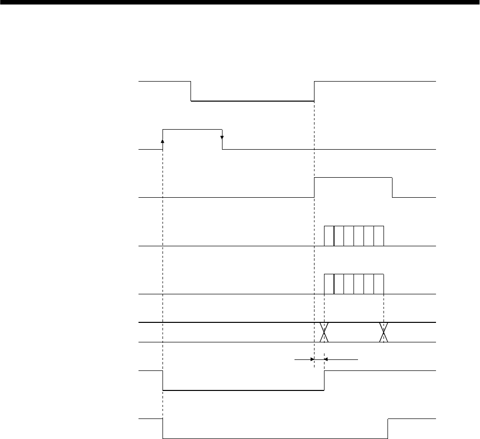
15 - 16
15. ABSOLUTE POSITION DETECTION SYSTEM
(b) If emergency stop is activated during servo-on
The ABS transfer mode (ABSM) is permissible while in the emergency stop state. In this case, the
base circuit and the ready (RD) are turned ON after the emergency stop state is reset.
OFF
ON
OFF
ON
OFF
ON
OFF
ON
OFF
ON
80[ms]
OFF
ON
OFF
ON
Servo-on
(SON)
Emergency stop
(EMG)
ABS transfer mode
(ABSM)
ABS request
(ABSR)
Send data ready
(TLC)
Send (ABS) data
Base circuit
Ready
(RD)
During transfer of ABS
ABS data
Operation
enabled
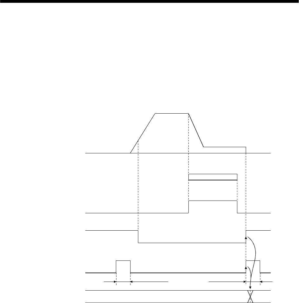
15 - 17
15. ABSOLUTE POSITION DETECTION SYSTEM
15.7.3 Home position setting
(1) Dog type home position return
Preset a home position return creep speed at which the machine will not be given impact. On detection
of a zero pulse, the home position setting (CR) is turned from off to on. At the same time, the servo
amplifier clears the droop pulses, comes to a sudden stop, and stores the stop position into the non-
volatile memory as the home position ABS data.
The home position setting (CR) should be turned on after it has been confirmed that the in-position
(D01 or INP) is on. If this condition is not satisfied, the home position setting warning (AL.96) will
occur, but that warning will be reset automatically by making home position return correctly.
The number of home position setting times is limited to 1,000,000 times.
OFF
ON
OFF
ON
OFF
ON
Servo Motor
Dog signal
(DOG)
Completion of
positioning
(D01 or INP)
Home position
setting (CR)
Home position
ABS data
Near-zero point dog
20 [ms] or more 20 [ms] or more
Update
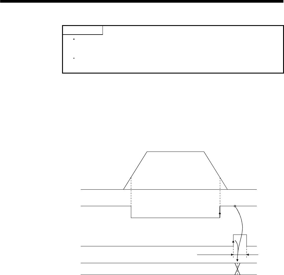
15 - 18
15. ABSOLUTE POSITION DETECTION SYSTEM
(2) Data set type home position return
POINT
Never make home position setting during command operation or servo motor
rotation. It may cause home position sift.
It is possible to execute data set type home position return when the servo
off.
Move the machine to the position where the home position is to be set by performing manual operation
such as jog operation to turn the motor shaft more than one revolution. When the home position
setting (CR) is on for longer than 20ms, the stop position is stored into the non-volatile memory as the
home position ABS data.
The home position setting (CR) should be turned on after it has been confirmed that the in-position
(D01 or INP) is on. If this condition is not satisfied, the home position setting warning (AL.96) will
occur, but that warning will be reset automatically by making home position return correctly.
The number of home position setting times is limited to 1,000,000 times.
OFF
ON
OFF
ON
Servo Motor
Completion of
positioning
(D01 or INP)
Home position
setting (CR)
Home position
ABS data
Manual feed (JOG, etc.)
(more than 1 revolution
of the motor shaft)
20 [ms] or more
Update
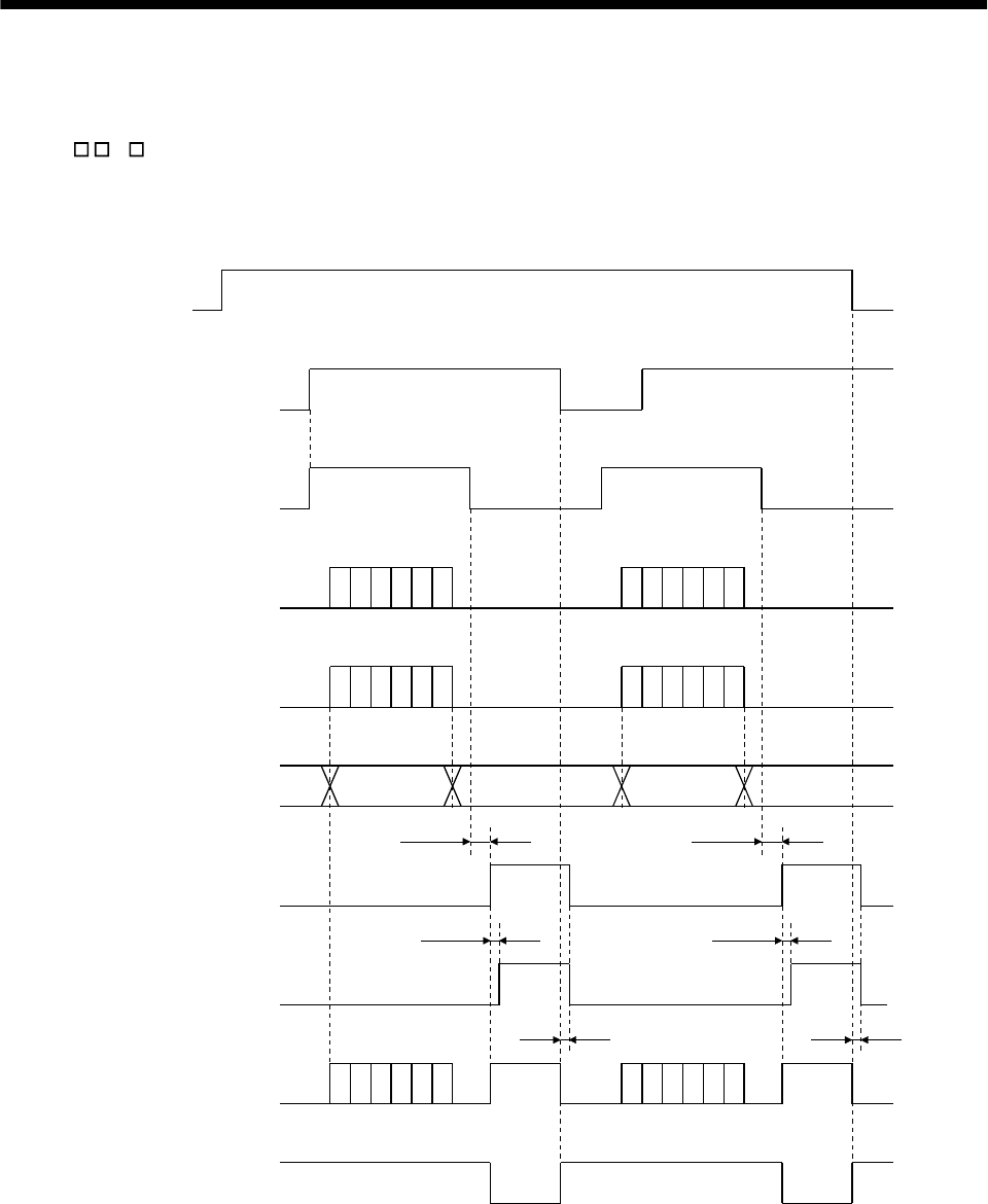
15 - 19
15. ABSOLUTE POSITION DETECTION SYSTEM
15.7.4 Use of servo motor with electromagnetic brake
The timing charts at power on/off and servo-on (SON) on/off are given below.
Preset " 1 " in parameter No. 1 to make the electromagnetic brake interlock (MBR) usable. When the
ABS transfer mode is ON, the electromagnetic brake interlock (MBR) is used as the ABS data bit 1.
Hence, make up an external sequence which will cause the electromagnetic brake torque to be generated
by the ABS mode (ABSM) and electromagnetic brake interlock (MBR).
OFF
ON
OFF
ON
OFF
ON
OFF
ON
OFF
ON
OFF
ON
OFF
ON
OFF
ON
OFF
ON
80 [ms]
20 [ms]
Tb
80 [ms]
20 [ms]
Tb
Power
supply
Servo-on
(SON)
ABS transfer mode
(ABSM)
ABS request
(ABSR)
ABS transmission
data ready
(ABST)
Send (ABS) data
Base circuit
Ready
(RD)
Electromagnetic
brake interlock
(MBR)
Electromagnetic
brake torque
During transmission
of ABS
During transmission
of ABS
ABS data ABS data

15 - 20
15. ABSOLUTE POSITION DETECTION SYSTEM
15.7.5 How to process the absolute position data at detection of stroke end
The servo amplifier stops the acceptance of the command pulse when stroke end (LSP LSN) is detected,
clears the droop pulses to 0 at the same time, and stops the servo motor rapidly.
At this time, the programmable controller keeps outputting the command pulse. Since this causes a
discrepancy between the absolute position data of the servo amplifier and the programmable controller, a
difference will occur between the position data of the servo amplifier and that of the programmable
controller.
To prevent this difference in position data from occurring, do as described below. When the servo
amplifier has detected the stroke end, perform jog operation or the like to clear the stroke end. After that,
switch the servo-on (SON) off once, then on again, or switch the power off once, then on again. This causes
the absolute position data of the servo amplifier to be transferred to the programmable controller,
restoring the normal data.
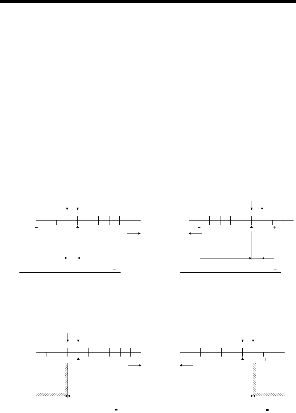
15 - 21
15. ABSOLUTE POSITION DETECTION SYSTEM
15.8 Examples of use
15.8.1 MELSEC-A1S (A1SD71)
(1) Instructions
The absolute coordinate system (programmable controller coordinate system) of the A1SD71 (AD71)
only covers the range in which the address increases (positive coordinate values) on moving away from
the machine home position (the position reached in the home position return operation). Therefore, if
the motor enters the range where the coordinate value is negative due to the load torque or a fall on a
vertical axis when the power is turned ON/OFF at a point near the machine home position, the system
fails to detect the absolute position. To prevent this problem, it is necessary to set the home position
(operation home position) for positioning in addition to the machine home position.
(a) The home position should be set in the direction in which the position address of the programmable
controller coordinate system increases on moving away from machine home position, as illustrated
below. Note that the home position for positioning must be more than one revolution of the servo
motor shaft from the machine home position.
If the address of the machine home position is changed to any value other than "0", the home
position should be set in the direction in which the position address increases on moving away from
the machine home position (machine home position after changing the home position address) and
at a point removed from the machine home position by more than one revolution of the motor shaft.
0
010000 50000
50000 0
010000
50000
20000
Machine home position
Home position
(operation home position)
Programmable
controller coordinate
system
A
BS
coordinate
system
a) If revolution direction parameter (Pr. 14) 0 b) If revolution direction parameter (Pr. 14) 1
Programmable
controller coordinate
system
ABS
coordinate
system
Direction in which
address increases
Direction in which
address increases
More than 1 revolution
of motor shaft
More than 1 revolution
of motor shaft
Machine home
positionHome position
20000 50000
(b) In the range where the address decreases on moving away from the machine home position, do not
turn the power supply to the programmable controller or the servo amplifier, the servo-on
pushbutton switch, or the PC-RESET switch, ON/OFF. If any of these operations are attempted,
the ABS coordinate error (Y4B) is output since the absolute position cannot be detected.
020000
0 10000 50000
50000 0
010000
50000
50000 20000
Machine home position Home position
A
BS
coordinate
system
a) If revolution direction parameter (Pr. 14) 0
Programmable
controller coordinate
system
ABS
coordinate
system
Direction in which
address increases
Absolute position data can be
detected
ABS coordinate
value error occurs
if power is turned
on within this range
ABS coordinate
value error occurs
if power is turned
on within this range
Machine
home positionHome position
Direction in which
address increases
Absolute position data can be
detected
b) If revolution direction parameter (Pr. 14) 1
Programmable
controller coordinate
system
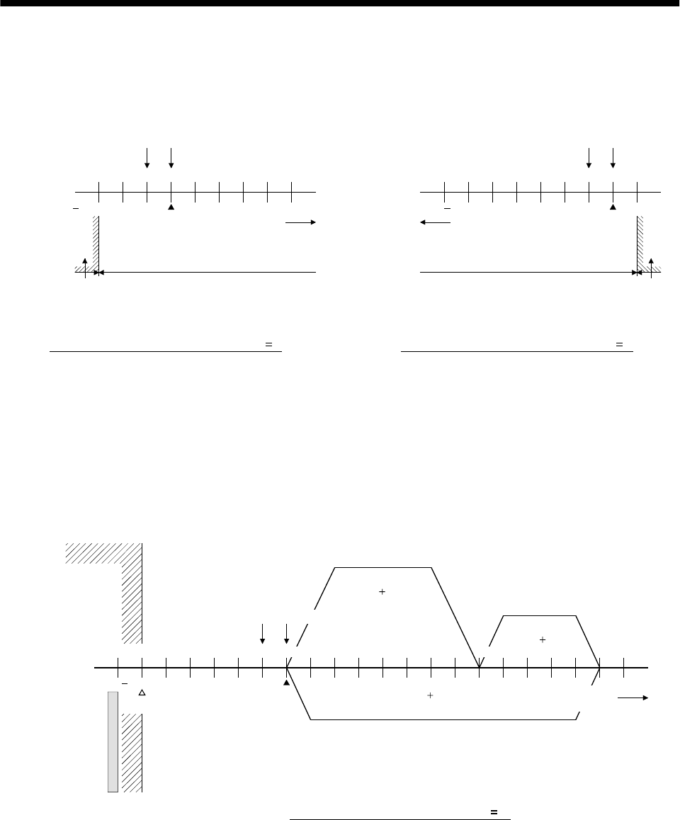
15 - 22
15. ABSOLUTE POSITION DETECTION SYSTEM
If the address of the machine home position is changed to any coordinate value other than "0", the
programmable controller coordinate system will be as illustrated below.
The power should be turned ON/OFF in the range in which the address increases on moving away
from the home position.
020000
20000 30000 70000
50000 0
2000030000
70000
50000 20000
00
Machine home position Home position
Programmable
controller coordinate
system
A
BS
coordinate
system
a) If revolution direction parameter (Pr. 14) 0
Programmable
controller coordinate
system
ABS
coordinate
system
Direction in which
address increases
Direction in which
address increases
Machine home position Home position
Absolute position data can be detected Absolute position data can be detected
ABS coordinate value error occurs if
power is turned on within this range
ABS coordinate value error occurs if
power is turned on within this range
* Home position address changed to "2000" * Home position address changed to "2000"
b) If revolution direction parameter (Pr. 14) 1
(c) In a positioning program, the address of the positioning point should be determined by adding the
home position address to the target position address.
Example) After home position return, execute positioning at 1) to 3).
1) Positioning at position address 80000
(PC coordinate 140000)
2) Positioning at position address 130000
(PC coordinate 190000)
3) Positioning at position address 0
(PC coordinate 60000)
0
50000
10000 50000
0
100000
50000
60000 150000
1)
(80000 60000)
2)
(130000 60000)
(0 60000)
3)
ABS coordinate
error region
Programmable
controller
coordinate
system
A
BS coordinate
system
Mechanical limit
Machine home position Home position (operation home
Stroke limit
* Home position address changed to "50000"
If revolution direction parameter (Pr. 14) 0
Direction in which
address increases
position)
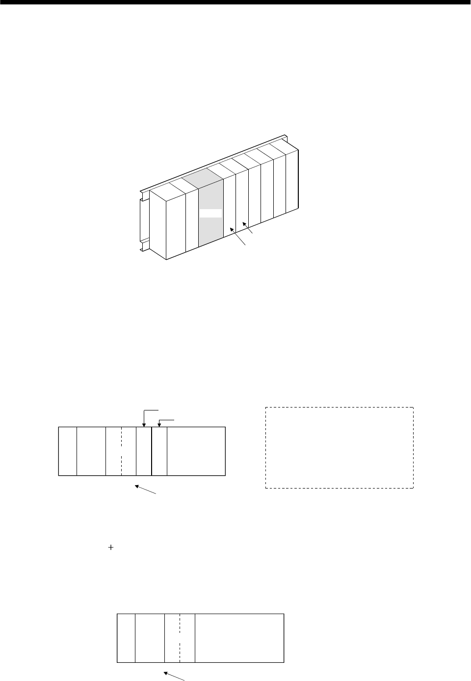
15 - 23
15. ABSOLUTE POSITION DETECTION SYSTEM
(d) Slot arrangement
The sequence programs presented in this section show I/O numbers (X, Y) assuming the
arrangement of modules on the main base unit is as illustrated below. A1SD71 is mounted at I/O
slots 0 and 1, a 16-point input module at slot 2, and 16-point output module at slot 3. If the actual
arrangement of the modules differs from this arrangement, change the X and Y numbers
accordingly.
The numbers of the devices (M, D, T, etc.) used in the program can be changed as required.
A1S
CPU
0
7
123456
A1SD71
I/O slot No.
Example arran
g
ement of modules
[Numbers used] X, X0-X, Y2F
16-point input module
16-point output module
Power
supply
(e) Points
1) The A1SD71 has 48 I/O points and occupies 2 slots. For I/O allocation using the GPP function,
follow the instructions given below.
First slot: Vacant slot 16 points
Second slot: Special function module 32 points
2) To execute the FROM/TO instruction for the A1SD71, use the head I/O number of the second
slot.
A1S
CPU A1SD71
X,Y000
to
X,Y00F
X,Y010
to
X,Y02F
X30 to X3F
Y40 to Y4F
I/O numbers to be set
with FROM/TO instruction
16-point input
module
16-point output
module
Note: The program example given
in (3) in this section is for 1-axis
control. Slot allocations are as
illustrated to the left. To use the
system for 2-axis control,
increase the number of I/O
points.
Therefore, the I/O number to be set with the FROM/TO instruction is head I/O number allocated
to the A1SD71 010H.
3) By setting "0 point of vacant slot" for the first slot of the A1SD71 in the "I/O allocation" of the
GPP function, the 16 points in the first slot can be saved.
In this case, the I/O number to be set with the FROM/TO instruction is the same number as the
head I/O number allocated to the A1SD71.
A1S
CPU A1SD71
X,Y000
to
X,Y00F
I/O numbers to be set with FROM/TO instruction
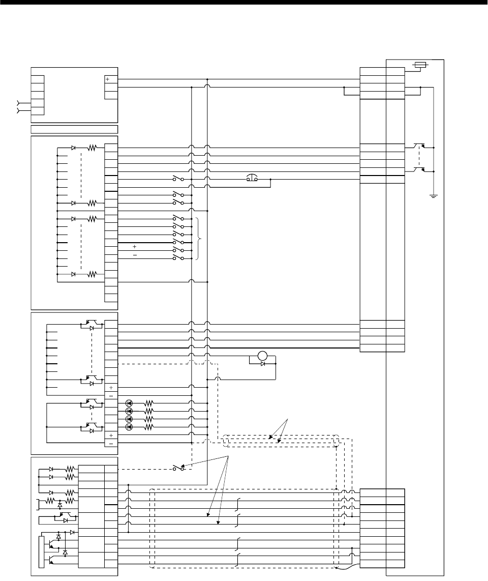
15 - 24
15. ABSOLUTE POSITION DETECTION SYSTEM
(2) Connection diagram
PULSE-
R
PULSE-
F
PGO
DOG
RDY
16B
16A
15B
15A
9B
9A
5B
6B
0
1
2
3
4
5
7
COM
8
9
A
B
C
D
E
F
COM
NC
NC
6
0
1
2
3
4
5
7
6
8
9
A
B
A1SD71-S2
A1SY40
A1SX40
A1SCPU
A1S62P
INPUT
AC100/200
COM1
COM2
(Note 3)
(Note 2)
12A
CLEAR
SD
NP
PP
SG
RD
P15R
CR
SG
19
4
8
10
20
3
2
Plate
5
8
9
14RES
ABSR
SON
ABSM
4
19
6
18
ZSP
15EMG
3
13
10
20SG
SG
VDD
COM
CN1B
24
24G
FGLG
Servo amplifier
CN1A
STOP 6A
5A
12B
17A
TLC
ALM
DO1
OP 14
OPC 11
General purpose
programmable controller
Power
supply
ABS bit 0/Completion of positioning
ABS bit 1/Zero speed
Send data ready/Torque limit control
Trouble
Servo-on
ABS transfer mode
ABS request
Alarm reset
Power supply
Power supply
Electromagnetic
brake output
(Note 4)
(Note 1)
JOG
JOG
Alarm reset
Emergency stop
Servo-on
Home position return
Operation mode I
Operation mode II
Position start
Position stop
Note 1. To be connected for dog type home position setting. The connection in Note 2 is not required.
2. To be connected for data set type home position setting. The connection in Note 1 is not required.
3. This circuit is for reference only.
4. The electromagnetic brake interlock (MBR) output should be controlled by connecting the programmable controller output to a relay.
RA2

15 - 25
15. ABSOLUTE POSITION DETECTION SYSTEM
(3) Sequence program example
(a) Conditions
This sample program is an ABS sequence program example for a single axis (X axis).
To transmit the ABS data using the OFF-to-ON change of the servo-on (SON) as the trigger.
1) When the servo-on (SON) and the GND of the power supply are shorted, the ABS data is
transmitted when the power to the servo amplifier power is turned ON, or at the leading edge of
the RUN signal after a PC reset operation (PC-RESET). The ABS data is also transmitted when
an alarm is reset, or when the emergency stop state is reset.
2) If a check sum discrepancy is detected in the transmitted data, ABS data transmission is retried
up to three times. If the check sum discrepancy is still detected after retrying, the ABS check
sum error is generated (Y4A ON).
3) The following time periods are measured and if the ON/OFF state does not change within the
specified time, the ABS communication error is generated (Y4A ON).
ON period of ABS transfer mode (Y41)
ON period of ABS request (Y42)
OFF period of ready to send ABS data (X32).
4) If the relationship between the polarity ( ) of the received ABS data and the setting value for
parameter No. 14 (rotating direction) of A1SD71 involves negative coordinate values, which
cannot be handled by the A1SD71, the ABS coordinate error is generated (Y4B ON).
(b) Device list X input contact Y output contact
X30 ABS bit 0 / completion of positioning Y40 Servo-on
X31 ABS bit 1 / zero speed Y41 ABS transfer mode
X32 Send ABS data ready / torque limit control Y42 ABS request
X33 Servo alarm Y43 Alarm reset
X34 Error reset X44 (Note 2) Electromagnetic brake output
X35 Servo emergency stop Y45 (Note 1) Clear
X36 Servo-on Y48 Servo alarm
X37 Home position return start Y49 ABS communication error
X38 Operation mode I Y4A ABS check sum error
X39 Operation mode II Y4B ABS coordinate error
D register M contact
D0 ABS data transmission counter M0 ABS data transmission start
D1 Check sum transmission counter M1 Sum check completion
D2 Check sum addition counter M2 Sum check discrepancy
D3 ABS data: Lower 16 bits M3 ABS data ready
D4 ABS data: Upper 16 bits M4 Transmission data read enabled
D5 ABS data 2-bit receiving buffer M5 Check sum 2 bits read completion
D6 Check data in case of check sum error M6 ABS 2 bits read completion
D7 Retry frequency M7 ABS 2 bits request
D8 Forward rotation direction M8 Servo-on request
D9 Home position address: Lower 16 bits M9 Servo alarm
D10 Home position address: Upper 16 bits M10 ABS data transmission retry start pulse
D100 Received shift data: Lower 16 bits M11 Retry flag setting
D101 Received shift data: Upper 16 bits M12 Retry flag reset
T timer M13 PLS processing command
T0 ABS transfer mode timer M20 (Note 1) Clear (CR) ON timer request
T1 ABS request response timer M21 (Note 2) Data set type home position return request
T2 Retry wait timer C counter
T3 Ready to send response timer C0 ABS data receive frequency counter
T10 (Note 1) Clear (CR) ON timer C1 Check sum receive frequency counter
T200 Transmitted data read 10ms delay timer C2 Retry counter
Note 1. Necessary when data set type home position return is executed.
2. Necessary in the event of electromagnetic brake output.
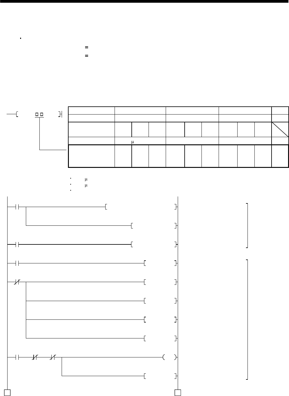
15 - 26
15. ABSOLUTE POSITION DETECTION SYSTEM
(c) ABS data transfer program for X axis
This sequence program example assumes the following conditions:
Parameters of the A1SD71-S2 positioning module
1) Unit setting : 3 pulse (PLS)
2) Travel per pulse : 1 1 pulse
To select the unit other than the pulse, conversion into the unit of the feed command value per
pulse is required. Hence, add the following program to the area marked Note in the sequence
program.
<Additional program>
Item mm inch degree pulse
Unit setting 0 1 2 3
Travel per pulse 0.1 to 1.0 to 10.0 0.00001
to 0.0001
to 0.001
to 0.00001
to 0.0001
to 0.001
to
Unit of travel m/PLS inch/PLS degree/PLS PLS
D * P K D3 D3
Constant K for
conversion into
unit of travel 1 to 10 to 100 1 to 10 to 100 1 to 10 to 100 None
Reference
For 1 m/PLS, set constant K to 10
For 5 m/PLS, set constant K to 50
When the unit setting is pulse, the additional program is not required.
M9038
K1K1K201H0001TOP
M9039
X36
D7K3MOV
M8SET
M8 M9 M11
1 1
X36
M3RST
M8RST
C0RST
C1RST
A0D100DMOV
Y40
M0PLS
A1SD71 error reset
Setting retry count (3 times)
Loading received shift data
Servo-on request
Resetting ready to send
Resetting servo-on request
Resetting ABS transfer
counter at servo OFF
Resetting checksum transfer
counter at servo OFF
Servo-on output
ABS I/F start
(To be continued)
Initial
pulse
ON
PC RUN
Servo-on PB
Servo-on
PB
Servo-on
request
Error
flag
Retry flag
setting
Initial setting
Servo-on control
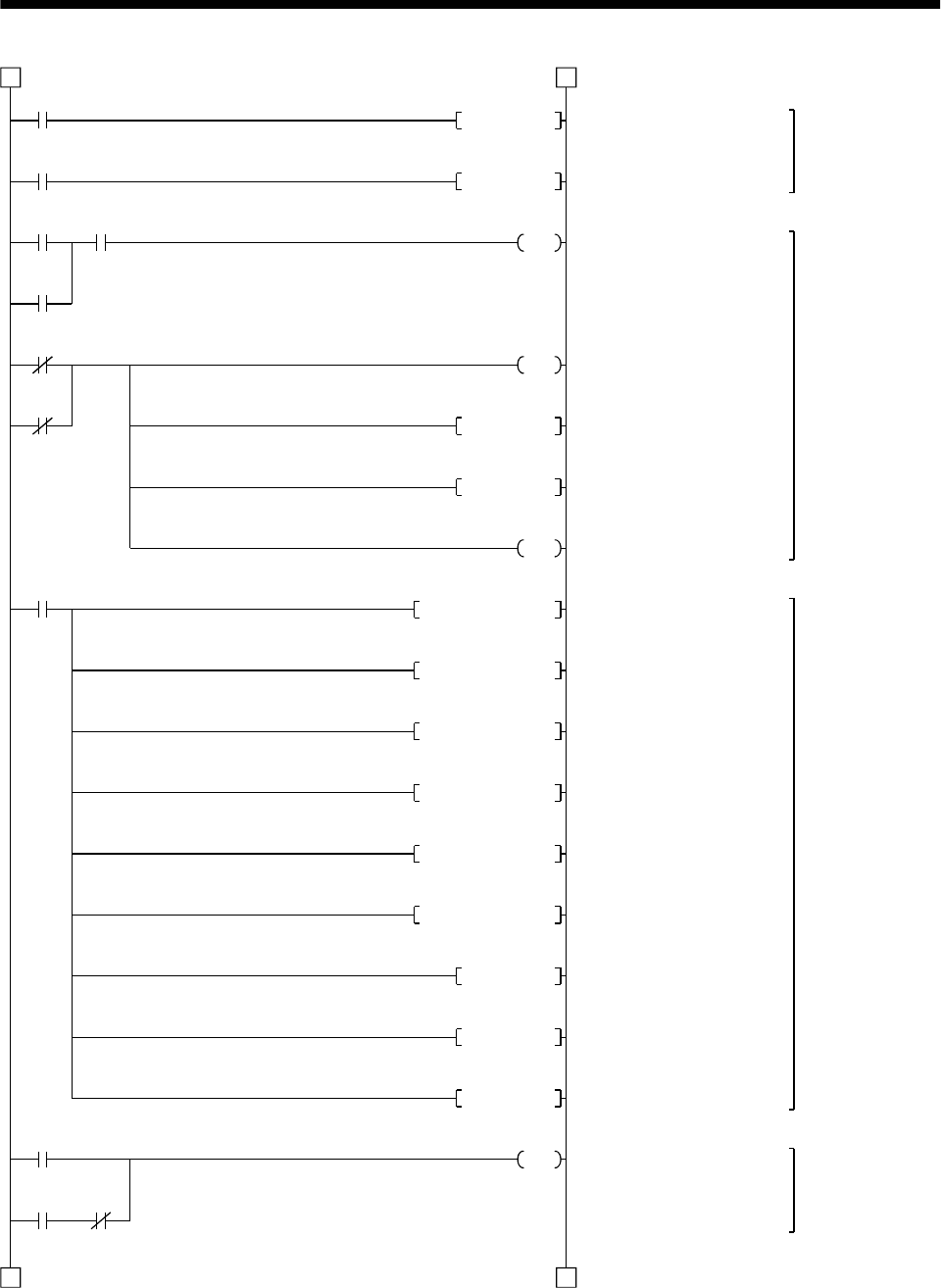
15 - 27
15. ABSOLUTE POSITION DETECTION SYSTEM
M8
M12PLS
M12
X34 M9
Y43
X35
Y43
X33
M0
D0K16MOV
M0
Y41 C1
1 1
2 2
C2RST
M9
M3RST
M8RST
Y48
D1K3MOV
D2 K0MOV
D5K0MOV
D9K0DMOV
A0K0DMOV
Y4BRST
C0RST
C1RST
Y41
Setting retry flag
Resetting retry counter
ABS data
transmission
retry control
Servo-on request
Retry flag reset request
Error reset
PB
Error flag
Alarm reset
Emergency
stop PB
Servo alarm
ABS data
transfer
start
Alarm reset output
Error flag output
Resetting ready to send
Resetting servo-on request
Servo alarm
Initializing ABS data transfer
counter
Initializing check sum transfer
counter
Initializing check sum register
Initializing ABS data register
Initializing ABS data register
Initializing ABS data register
Resetting error for ABS
coordinate
Resetting ABS transfer
counter
Resetting check sum transfer
counter
ABS transfer mode
Servo alarm
detection, alarm
reset control
ABS transfer
mode
Initial setting
ABS transfer
mode control
(Continued from preceding page)
(To be continued)
ABS data transfer
start
ABS
transfer
mode
Checksum
counter
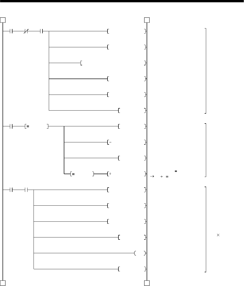
15 - 28
15. ABSOLUTE POSITION DETECTION SYSTEM
C0 C1 Y41
D3A0DMOVP
K1D8K7872H0001FROMP
M13PLS
M13
M4 C0
C1
2 2
3 3
A0K0MOVP
D8H0004WAND
A1H8000WAND
D4NEG
D4K1
D3NEG
D4K1
D5K1X30MOV
D5H0003WAND
A0D5WOR
K2ROR
M5PLS
D1
D8 K4
K0 D3
Detecting absolute
position polarity
and A1SD71
rotating direction
Reversing polarity o
f
absolute position
Reading checksum
6 bits
(2 bit 3 times)
Saving ABS 32-bit data
Clearing register
*1 Reading X-axis rotating
direction parameter
Rotation direction parameter
mask
ABS data sign mask
PLS processing command
Reversing polarity of upper
16 bits
Subtraction for upper 16 bits
Reversing polarity of lower
16 bits
Reading 4 bits
Masking 2 bits
Adding 2 bits
Right rotation of A0 2 bits
Counting check sum data
reception frequency
Completion of reading, 2 bits
of check sum
Counter Check sum
counter
ABS
transfer
mode
PLS processing
command
Read
enabled ABS data
counter
Rotation direction
judgment
(Continued from preceding page)
(To be continued)
Lower 16 bits 0
D4 1 D4
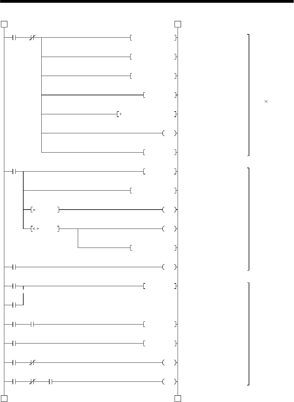
15 - 29
15. ABSOLUTE POSITION DETECTION SYSTEM
M4 C0
D5K1X30MOV
K2DROR
D2D2D5
C0
C1
C2
M6
M5
Y41 X32
M7
Y42 X32
Y42 X32 T200
3 3
4 4
D5H0003WAND
A0D5WOR
D0
M6PLS
K10RORP
A0H003FWAND
M1
M2
D6A0MOV
Y4A
Y42RST
M7PLS
Y42SET
T200
K1
M4
D2 A0
D2 A0
Reading ABS data
32 bits
(2 bits 16 times)
Detecting ABS data
check sum error
ABS request
control
Reading 4 bits
Masking 2 bits
Adding 2 bits
Right rotation of A0 2 bits
Adding check sum
Counting frequency of ABS
data reception
Completion of reading: 2 bits
of ABS data
Right rotation of A0 10 bits
Masking check sum
Sum check OK
Sum check NG
Sum check memory
ABS check sum error
Resetting ABS request
ABS 2 bits request
Setting ABS request
10ms delay timer
Transmission data read
enabled
(Continued from preceding page)
(To be continued)
Read
enabled ABS data
counter
Check
sum
counter
Retry counter
ABS 2 bits read
completion
Check sum 2 bits read completion
ABS transfer
mode Send data
ready
ABS 2 bits request
ABS
request
Send data ready
10ms delay timer
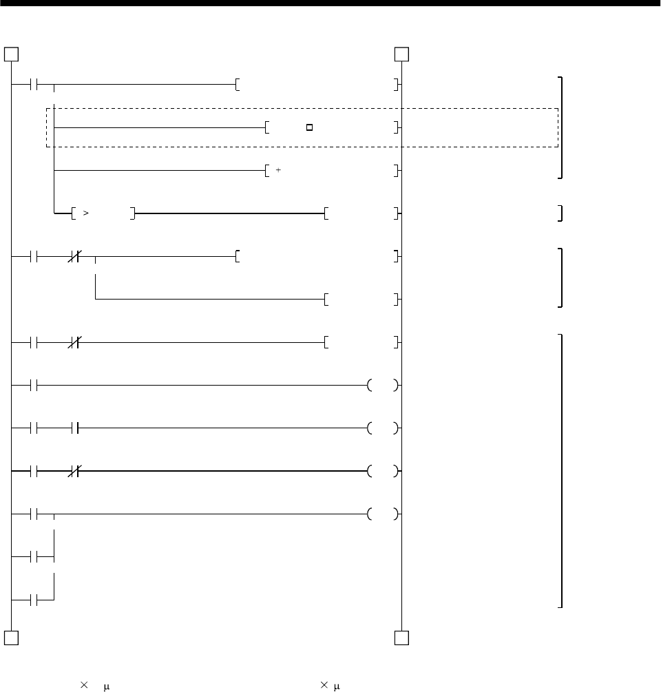
15 - 30
15. ABSOLUTE POSITION DETECTION SYSTEM
M1
K1D9K7912H0001DFROP
M1 Y4B
D3D3D*P
Y4BSET
K1D3K41H0001DTOP
Y49 X36
Y41 T0
Y41 Y42
Y41 X32
T0
T1
T3
4 4
D3D9D3D P
M3SET
Y41RST
K50
T1
K10
T3
K10
Y49
(Note)
55
K0DD3
Restoring absolute
position data
Detecting ABS
coordinate error
Writing ABS data
to A1SD71
ABS communication
error detecting
*1 A1SD71: reading home
position address
Inserting constant K for conversion
into the unit of feed per pulse
Adding home position address
to absolute position
Setting ABS coordinate error
*1 X-axis: Present position
change ABS data "ready"
ABS data "ready"
Resetting ABS transfer mode
ABS transfer mode timer (5s)
ABS request response timer
(1s)
Ready to send response
timer (1s)
ABS communication error
Note. When the unit setting parameter value of the A1SD71 positioning module is changed from "3" (pulse) to "0" (mm),
the unit is 0.1 m for the input value. To change the unit to 1 m, and this program to multiple the feed value
by 10.
(Continued from preceding page)
(To be continued)
Check sum OK
Check
sum OK
ABS coordinate error
ABS commu-
nication error Servo-on PB
ABS transfer mode
ABS transfer
mode ABS request
ABS transfer
mode
Send data ready
ABS transfer NG
ABS request NG
Send data ready NG
K
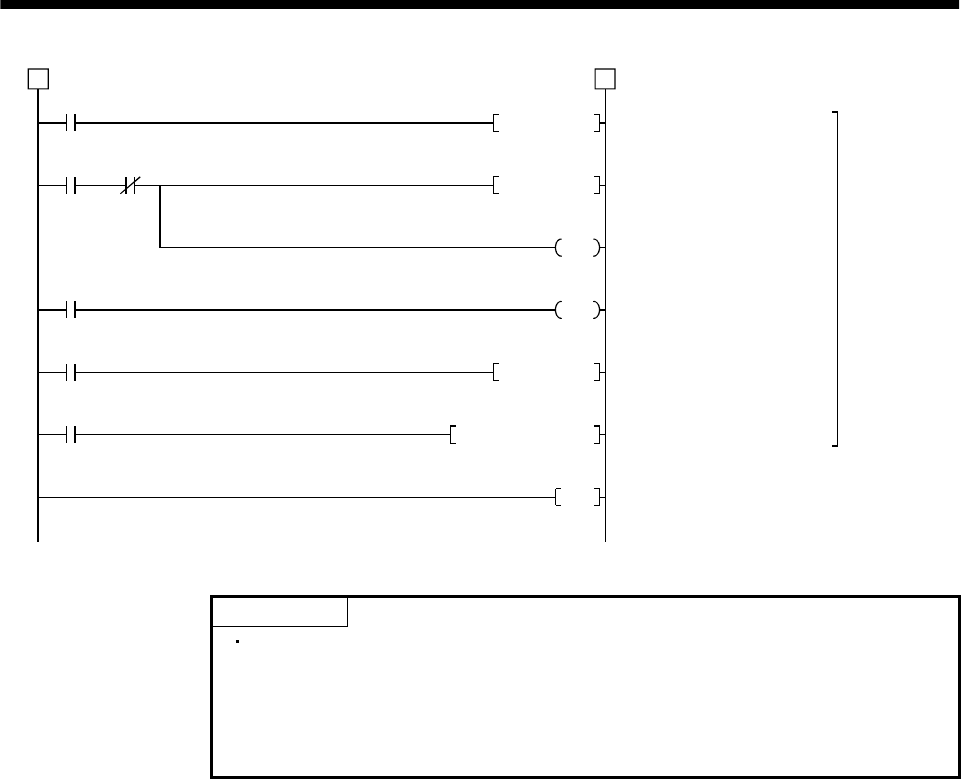
15 - 31
15. ABSOLUTE POSITION DETECTION SYSTEM
M2
M10 C2
M11
T2
M9039
END
5 5
M10PLS
M11SET
C2
D7
T2
K1
M11RST
D100A0DMOV
ABS transfe
r
retry control
ABS transfer retry start pulse
Setting retry flag
Retry counter
Retry wait timer (100ms)
Resetting retry flag
Saving received shift data
Check sum NG
Retry start
pulse
Retry
counter
Retry flag set
Retry wait timer
PC RUN
(Continued from preceding page)
POINT
When absolute position data is received at power ON, for example, if a
negative coordinate position which cannot be handled by the A1SD71 is
detected, the ABS coordinate error (Y4B ON) is generated. If this error is
generated, move the axis into the positive coordinate zone in JOG operation.
Then, turn OFF the servo-on pushbutton switch and turn it ON again.

15 - 32
15. ABSOLUTE POSITION DETECTION SYSTEM
(d) X-axis control program
This precludes execution of the X-axis start program while M3 (ready to send the ABS data) is
OFF.
When M3 (ready to send the ABS data)
is turned ON, the X-axis start command
executes the X-axis start program.
X-axis start program
Positioning
mode
X-axis start
command M3
Ready to
send the
ABS date
(e) Dog type home position return
For an example of a program for the dog type home position return operation, refer to the home
position return program presented in the User's Manual for A1SD71.
(f) Data set type home position return
After jogging the machine to the position where the home position (e.g.500) is to be set, choose the
home position return mode set the home position with the home position return start (PB ON).
After switching power on, rotate the servo motor more than 1 revolution before starting home
position return.
Do not turn ON the clear (CR) (Y45) for an operation other than home position return. Turning it
ON in other circumstances will cause position shift.
M9039
T10
M20PLS
M21SET
Y2D PC ready
Clear (CR) ON timer request
Clear (CR) 100ms ON timer
Setting data set type home position return request
Resetting data set type home position return request
Clear (CR) ON
Setting X-axis home position address "500"
in the data register
*1:Changing X-axis home position address
PC RUN
Clear signal 100ms ON timer
Home position return mode
Home position
Y41
return mode X30 X37
ABS
transfer
mode
Positioning
completion Home position
return start PB
(Note 1)
M20
M21
Clear (CR) ON
timer request
T10
K1
M21RST
Data set type home
position return request
M21
Data set type home
Y45
position return request
D9K500DMOVP
K1D9H0001DTOP K7912
K1D9H0001DFROP K7912
K1D9H0001DTOP K41 *1:Changing X-axis present position data
(Note 1)
(Note 2)
Note 1. If data of the home position address parameter is not written by using an A6GPP programming tol, etc. before
starting a program for data set type home position return, the circuits indicated by Note 1 are necessary and the
circuit indicated by Note 2 is not necessary.
2. Contrary to Note 1 above, if the home position address is written in the home position address parameter.
the circuit indicated b
y
Note 3 is necessar
y
and the circuits indicated b
y
Note 1 are not necessar
y
.
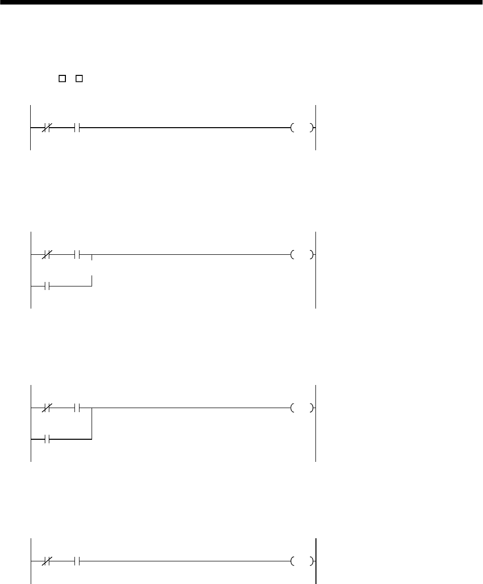
15 - 33
15. ABSOLUTE POSITION DETECTION SYSTEM
(g) Electromagnetic brake output
During ABS data transfer (for several seconds after the servo-on (SON) is turned on), the servo
motor must be at a stop.
Set "1 1 "in parameter No. 1 of the servo amplifier to choose the electromagnetic brake interlock
(MBR).
Y41 X31
Y44 Electromagnetic brake output
ABS
transfer
mode
Brake (MBR)
(h) Positioning completion
To create the status information for servo positioning completion.
During ABS data transfer (for several seconds after the servo-on (SON) is turned on), the servo
motor must be at a stop.
Y41 X30
M
Y41
Completion of servo positioning
ABS transfer
mode Positioning
completion
ABS transfer
mode
(i) Zero speed
To create the status information for servo zero speed
During ABS data transfer (for several seconds after the servo-on (SON) is turned on), the servo
motor must be at a stop.
Y41 X31
M
Y41
Servo zero speed
ABS transfer
mode Zero
speed
ABS transfer
mode
(j) Torque limiting
To create the status information for the servo torque limiting mode
During ABS data transfer (for several seconds after the servo-on (SON) is turned on), the torque
limiting must be off.
Y41 X32
MServo torque limiting mode
ABS transfer
mode Torque limiting
mode
15 - 34
15. ABSOLUTE POSITION DETECTION SYSTEM
(4) Sequence program - 2-axis control
The following program is a reference example for creation of an ABS sequence program for the second
axis (Y axis) using a single A1SD71 module. Create a program for the third axis in a similar manner.
(a) Y-axis program
Refer to the X-axis ABS sequence program and create the Y-axis program.
Assign the X inputs, Y outputs, D registers, M contacts, T timers and C counters of the Y axis so
that they do not overlap those of the X axis.
The buffer memory addresses of the A1SD71 differ between the X and Y axes. The instructions
marked *1 in the program of Section 15.8.1 (3), (c) should be changed as indicated below for use
with the Y axis:
[Program configuration]
X-axis ABS sequence program
(Program in Section 15.8.1 (3), (f))
Y-axis ABS sequence program
(Refer to the X-axis program and write the Y-axis
program)
[FROMP H0001 K7872 D8 K1]
[DFROP H0001 K7912 D9 K1]
[DTOP H0001 K41 D3 K1]
[FROMP H0001 K7892 D8 K1]
[DFROP H0001 K7922 D9 K1]
[DTOP H0001 K341 D3 K1]
(b) Data set type home position return
Arrange the data set type home position return programs given in Section 15.8.1 (3), (f) in series to
control two axes.
Refer to the X-axis data set type home position return program and create the Y-axis program.
Assign the X inputs, Y outputs, D registers, M contacts and T timers of the Y axis so that they do
not overlap those of the X axis.
The buffer memory addresses of the A1SD75 differ between the X and Y axes. The instructions
marked *1 in the program of Section 15.8.1 (3), (f) should be changed as indicated below for use
with the Y axis:
[Program configuration]
X-axis data set type home position return program
(Program in Section 15.8.1 (3), (f))
Y-axis data set type home position return program
(Refer to the X-axis program and write the Y-axis
program)
[DTOP H0001 K7912 D9 K1]
[DTOP H0001 K41 D9 K1]
[DTOP H0001 K7922 D9 K1]
[DTOP H0001 K341 D9 K1]
15 - 35
15. ABSOLUTE POSITION DETECTION SYSTEM
15.8.2 MELSEC FX(2N)-32MT (FX(2N)-1PG)
(1) Connection diagram
(a) FX-32MT (FX-1PG)
3.3k
3.3k
3.3k
N
COM2
Y4
Y5
Y6
Y10
24
SG
SG
S/S
DOG
STOP
VH
VL
FPO
FP
COM0
RP
RPO
COM1
CLR
LPower supply
FX-32MT
SG 10
DO1 4
ZSP 19
TLC 6
ALM 18
RD
EMG 15
SON 5
ABSM 8
ABSR 9
RES 14
DOG
SD
15V
FX-1PG
Servo amplifier
COM
RUN
X1
X2
X3
X4
X5
X6
X7
X10
X11
X12
X13
X14
X15
COM1
Y0
X0
PC-RUN
Y1
Y2
Y3
Y7
COM3
Y11
Y12
Y13
RA2
COM 13
PGO
PGO
VDD 3
PP 3
SG 20
NP 2
SG 10
CR 8
P15R 4
OP 14
SD Plate
24V
SD
3.3k
24V CN1B
OPC CN1A
11
ABS bit 0/Completion of positioning
ABS bit 1/Zero speed
Send data ready/Torque limit control
Alarm
Servo ready
JOG( )
JOG( )
Alarm reset
Servo-on
Position start
Position stop
Home position return start
1PG error reset
Emergency stop CN1A
19
Servo-on
ABS transfer mode
ABS request
Alarm reset
Electromagnetic
brake output
(Note 3)
(Note 2)
Servo alarm
ABS communication
error
ABS check sum error
Pulse train for forward rotation
Pulse train for reverse rotation
Clear
Z-phase pulse
(Note 1)
Note 1. To be connected for the dog type home position setting. At this time, do not connect the portions marked (Note 2).
2. To be connected for the data set type home position setting. At this time, do not connect the portions marked (Note 1).
3. The electromagnetic brake interlock (MBR) should be controlled by connecting the programmable controller output to a relay.
15 - 36
15. ABSOLUTE POSITION DETECTION SYSTEM
(b) FX2N-32MT (FX2N-1PG)
3.3k
3.3k
3.3k
CN1B
N
COM2
Y4
Y5
Y6
Y10
24
S/S
DOG
STOP
VIN
FP
COM0
RP
COM1
CLR
LPower supply
FX2N-32MT
SG 10
DO1 4
ZSP 19
TLC 6
ALM 18
RD
EMG 15
SON 5
ABSM 8
ABSR 9
RES 14
DOG
SD
FX2N-1PG
Servo amplifier
COM
X1
X2
X3
X4
X5
X6
X7
X10
X11
X12
X13
X14
X15
COM1
Y0
X0
Y1
Y2
Y3
Y7
COM3
Y11
Y12
Y13
RA2
COM 13
PGO
PGO
PP 3
SG 20
NP 12
SG 10
CR 8
P15R 4
OP 14
SD
SD
24V
VDD 3
Plate
24V
OPC 11
CN1A
CN1A
19
3.3k
JOG( )
JOG( )
Alarm reset
Servo-on
Position start
Position stop
Home position return start
1PG error reset
ABS bit 0/Completion of positioning
ABS bit 1/Zero speed
Send data ready/Torque limit control
Alarm
Servo ready
Emergency stop
(Note 2)
Electromagnetic
brake output
(Note 3)
Servo alarm
ABS communication
error
ABS check sum error
Servo-on
ABS transfer mode
ABS request
Alarm reset
(Note 1)
Pulse train for forward rotation
Pulse train for reverse rotation
Clear
Z-phase pulse
Note 1. To be connected for the dog type home position setting. At this time, do not connect the portions marked (Note 2).
2. To be connected for the data set type home position setting. At this time, do not connect the portions marked
(Note 1).
3. The electromagnetic brake interlock (MBR) should be controlled by connecting the programmable controller
output to a relay.
15V
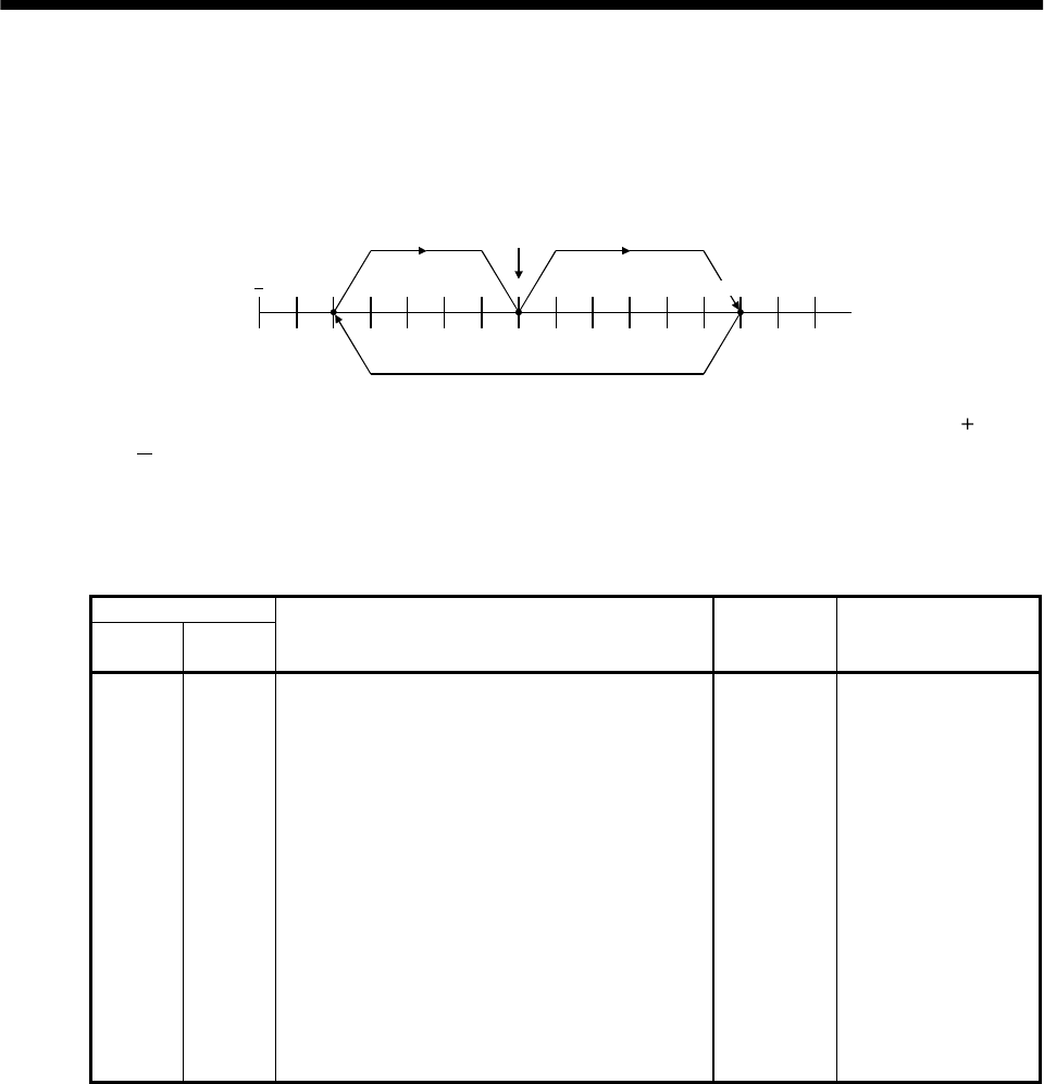
15 - 37
15. ABSOLUTE POSITION DETECTION SYSTEM
(2) Sequence program example
(a) Conditions
1) Operation pattern
ABS data transfer is made as soon as the servo-on pushbutton is turned on. After that,
positioning operation is performed as shown below:
300000 0
address
3) 1)
2)
Home position
300000
After the completion of ABS data transmission, JOG operation is possible using the JOG or
JOG pushbutton switch.
After the completion of ABS data transmission, dog type home position return is possible using
the home position return pushbutton switch.
2) Buffer memory assignment
For BFM#26 and later, refer to the FX2(N)-1PG User's Manual.
BMF No.
Upper 16
bits
Lower 16
bits
Name and symbol Set value Remark
-#0 Pulse rate A 2000
#2 #1 Feed rate B 1000
- #3 Parameter H0000 Command unit: Pulses
#5 #4 Max. speed Vmax 100000PPS
- #6 Bias speed Vbia 0PPS
#8 #7 JOG operation Vjog 10000PPS
#10 #9 Home position return speed (high speed) VRT 50000PPS
- #11 Home position return speed (creep) VCL 1000PPS
- #12 Home position return zero-point signal count N 2 pulses Initial value: 10
#14 #13 Home position address HP 0
- #15 Acceleration/deceleration time Ta 200ms Initial value: 100
- #16 Not usable
#18 #17 Target address (I) P(I) 0
#20 #19 Operation speed (I) V(I) 100000 Initial value: 10
#22 #21 Target address (II) P(II) 0
#24 #23 Operation speed (II) V(II) 10
- #25 Operation command H0000
3) Instructions
When the servo-on pushbutton switch and the GND of the power supply are shorted, the ABS
data is transmitted when the servo amplifier power is turned ON, or at the leading edge of the
RUN signal after a PC reset operation (PC-RESET). The ABS data is also transmitted when an
alarm is reset, or when the emergency stop state is reset.
If check sum discrepancy is detected in the transmitted data, the ABS data transmission is
retried up to three times. If the check sum discrepancy is still detected after retrying, the ABS
check sum error is generated (Y12 ON).
The following time periods are measured and if the ON/OFF state does not change within the
specified time, the ABS communication error is generated (Y11 ON).
ON period of ABS transfer mode (Y1)
ON period of ABS request (Y2)
OFF period of ready to send the ABS data (X2).
15 - 38
15. ABSOLUTE POSITION DETECTION SYSTEM
(b) Device list
X input contact Y output contact
X0 ABS bit 0 / completion of positioning Y0 Servo-on
X1 ABS bit 1 / zero speed Y1 ABS transfer mode
X2 Send ABS data ready/ torque limit control Y2 ABS request
X3 Servo alarm Y3 Alarm reset
X4 Alarm reset PB Y4 (Note 2) Electromagnetic brake output
X5 Servo emergency stop Y5 (Note 1) Clear
X6 Servo-on PB Y10 Servo alarm
X7 Servo ready Y11 ABS communication error
X10 JOG ( ) PB Y12 ABS check sum error
X11 JOG (−) PB
X12 Position start PB
X13 Position stop PB
X14 Home position return start PB
X15 1PG error reset
D register M contact
D0 ABS data: Lower 16 bits M0 Error flag
D1 ABS data: Upper 16 bits M1 ABS data transmission start
D2 Check sum addition counter M2 Retry command
D3 Check data in case of check sum error M3 ABS data read
D4 Transmission retry count in check sum
discrepancy M4 Spare
D24 Home position address: Lower 16 bits M5 Servo-on request
D25 Home position address: Upper 16 bits M6 Retry flag
D106
D107 1PG present position address: Lower 16 bits
1PG present position address: Upper 16 bits M10
M11
M12
M13
ABS data 2 bit receiving buffer
M20
M51 ABS data 32 bit buffer
M52
M57 Check sum 6 bit buffer
M58
M59 For checksum comparison
T timer M62 Sum check discrepancy (greater)
T200 Retry wait timer M63 Sum check discrepancy
T201 ABS transfer mode timer M64 Sum check discrepancy (less)
T202
T203
T204
T210 (Note 1)
ABS request response timer
Ready to send response timer
ABS data waiting timer
Clear (CR) ON timer
M70 (Note 1)
M71 (Note 1)
M99
Clear (CR) ON timer request
Data set type home position return request
ABS data ready
C counter
C0 All data reception frequency counter (19 times)
C1 Check sum reception frequency counter
C2 ABS data reception frequency counter (16 times)
Note 1. Necessary when data set type home position return is executed.
2. Necessary in the event of electromagnetic brake output.
15 - 39
15. ABSOLUTE POSITION DETECTION SYSTEM
(c) ABS data transfer program for X-axis
M8002
D24K0DMOV
K1K0K3K0TO
K1K100000K4K0DTO
K1K10000K7K0DTO
K1K50000K9K0DTO
K1K1000K11K0TO
K1K2K12K0TO
K1D24K13K0DTO
K1K200K15K0TO
K1K100000K19K0DTO
1 1
D100K300000DMOV
D102K 250000DMOV
D104K0DMOV
ZK0DMOV
D4K4DMOV
Setting home position address
to 0
Setting 1PG pulse command
unit
1PG max. speed: 100 kpps
1PG Jog speed: 10 kpps
1PG home position return
speed: 50 kpps
1PG creep speed: 1 kpps
1PG home position return
zero-point count: twice
1PG home position address
setting
1PG acceleration/deceleration
time: 200ms
1PG operation speed:
100kpps
Position move account 1:
300000 pulses
Position move account 2:
250000 pulses
Position move account 3:
0 pulses
Clearing index registers V, Z
Setting "4 times" for check
sum error transmission
frequency
Initial setting
Initial
pulse
(To be continued)
15 - 40
15. ABSOLUTE POSITION DETECTION SYSTEM
X6 M6
M5SET
M5 Y12
X6
Y0
Y12
1 1
2 2
M64M62ZRST
M1PLS
C1RST
C2C0ZRST
M99RST
M5RST
Y1RST
Y2RST
M6RST
Servo-on request
Servo-on output
ABS data transmission start
Clearing retry counter
Resetting ready to send ABS
data
Resetting servo-on request
Resetting ABS transfer mode
Resetting ABS request
Resetting retry flag
Resetting check sum
judgement
Resetting communication
counter
Servo-on
PB Retry
Servo-on
request
Servo-on PB
(Continued from preceding page)
(To be continued)
Servo-on and
retry control
M1 M6
ABS
transmission
start
Retry
M0 Y11
Error
flag ABS
communication
error
ABS check
error
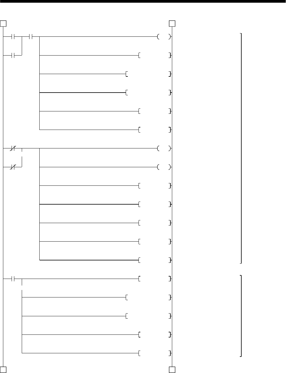
15 - 41
15. ABSOLUTE POSITION DETECTION SYSTEM
X4 M0
Y3
Y3
C1RST
M64M0ZRST
X5
X3
M1
2 2
3 3
D3D0ZRST
C2RST
C0RST
M0
Y10
Y1RST
Y2RST
M99RST
M5RST
M6RST
Y1SET
M64M10ZRST
D2D0ZRST
C2RST
C0RST
Alarm reset output
Clearing retry counter
Clearing ABS data receiving
area
Clearing ABS receive data
buffer
Resetting ABS data reception
counter
Resetting all data reception
counter
Error flag output
Servo alarm output
Resetting ABS transfer mode
Resetting ABS request
Resetting ready to send
Resetting servo-on request
Resetting retry flag
ABS transfer mode ON
Clearing ABS data reception
area
Clearing ABS receiver data
buffer
Resetting ABS data reception
counter
Resetting all data reception
counter
Servo alarm
detection, alarm
reset control
ABS transfer
mode
Initial setting
Alarm
reset PB Error flag
Alarm reset
Emergency stop PB
Servo alarm
(Continued from preceding page)
(To be continued)
ABS data
transmission start
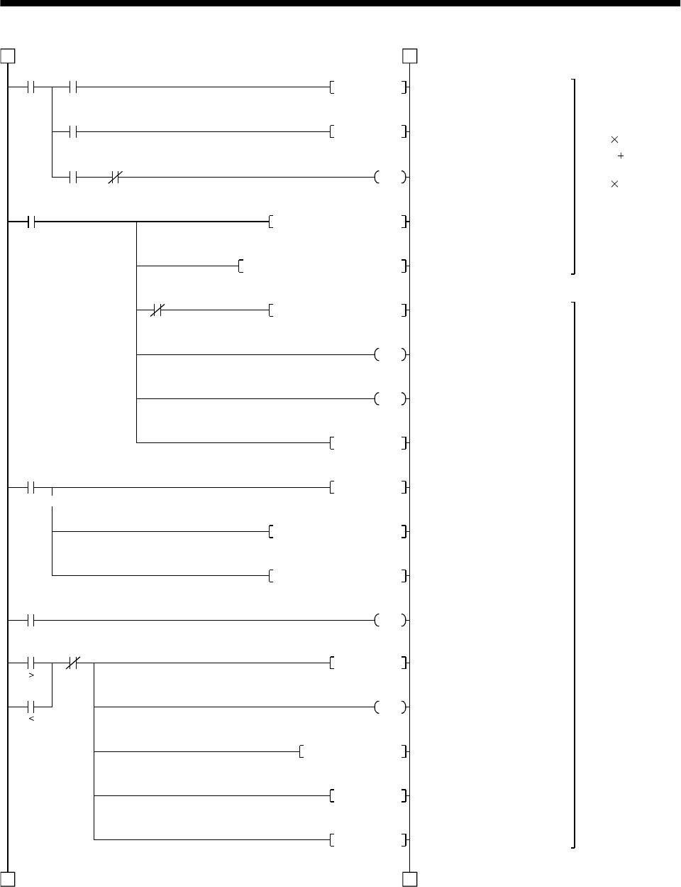
15 - 42
15. ABSOLUTE POSITION DETECTION SYSTEM
Y1 X2
M3PLS
M3
Y2 X2
C2
C2
C0
M64
3 3
4 4
D3K2M52MOV
Y2SET
K1M10H0003K1X0WANDP
K2K38M20M10SFTR
D2D2K1M10ADDP
K16
C0
K19
Y2RST
Y1RST
D2D2H003FWANDP
M62D2K2M52CMPP
C1
M62 C1
Y12
M2PLS
T200
K10
M6SET
M5RST
ABS data 32 bits
(2 bits 16 times)
Check sum 6 bits
(2 bits 3 times)
Detection of ABS
check sum error,
retry control
Resetting ABS data
ABS request ON
Masking ABS data 2 bits
Right shift (2 bits) of ABS data
Check sum addition
Updating ABS data reception
counter
Updating all data reception
counter
Resetting ABS request
Resetting ABS transfer mode
Masking check sum 6 bits
Comparison of check sum
ABS data check sum error
Retry command
Setting retry wait timer: 100ms
Storing check sum value in the
case of check sum error
Retry flag ON
Resetting servo-on request
ABS
transfer
mode
Send data ready
ABS data read
ABS
request Send data
ready
All data reception counter
Retry counter
Retry
counter
(Continued from preceding page)
(To be continued)
T204
T204
K1 ABS data waiting timer 10ms
ABS data waiting timer
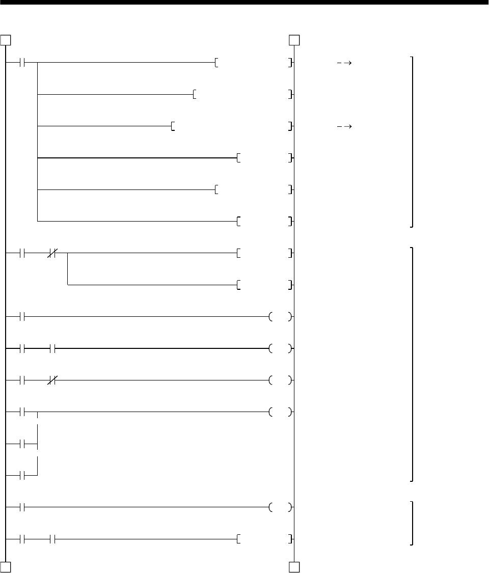
15 - 43
15. ABSOLUTE POSITION DETECTION SYSTEM
M63
D0K8M20DMOVP
D0D24D0DADDP
K1D0K26K0DTOP
M99SET
Y11 X6
Y1
T201
Y1 Y2
Y1 X2
T201
T202
T203
M2
T200 M6
4 4
5 5
M64M62ZRST
M6RST
Y1RST
Y2RST
K500
T202
K100
T203
K100
Y11
C1
D4
M5SET
Writing absolute
position data to
1PG
Detecting ABS
communication
error
ABS transfer
retry control
ABS data D0, D1
Adding 1PG home position
address
ABS data 1PG
Setting ABS data ready
Clearing check sum judging
area
Resetting retry flag
Detecting ABS
communication error
Resetting ABS request
ABS transfer mode 5s timer
ABS request response
1s timer
Ready to send response
1s timer
ABS communication error
Counting retry frequency
Setting servo-on request
(Continued from preceding page)
(To be continued)
Check
sum
match
ABS
communi-
cation error
Servo-on
PB
ABS transfer mode
ABS transfer
mode ABS request
ABS transfer
mode Send data ready
ABS transmission NG
ABS request NG
Send data ready NG
Retry command
Retry
wait
timer
Retry
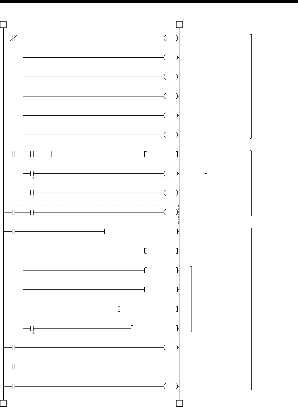
15 - 44
15. ABSOLUTE POSITION DETECTION SYSTEM
M8000
M109
X7 X12 M99
M120PLS
X10
JOG
X11
JOG
X7 X14
M120
K1D100ZK17K0DTO
M121K6ZDCMP
M122
INDX 6
ZK0DMOV
X12
M0
X16
5 5
6 6
M110
M111
M112
M102
M103
M104
M105
M106
108SET
ZDINC
ZDINC
M101
M100
(Note)
1PG control
command
(not used)
Operation
command
control
Position
command
control
Note. Program example for the dog type home position return. For the data set type home position return, refer to the
program example in (2), (d) in this section.
Start command pulse
1PG JOG command
1PG JOG command
1PG home position return
start
Setting motion distance
1PG start
Index processing
1PG stop command
1PG error reset
(Continued from preceding page)
(To be continued)
Normally
OFF
Servo
ready Position
start PB ABS data
ready
Servo ready Home position return PB
Position
start
command
pulse
Position
stop PB
Error flag
1PG error reset
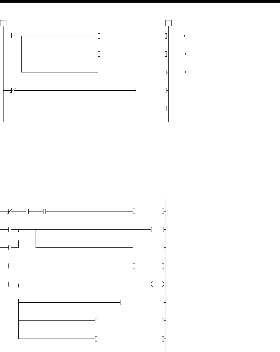
15 - 45
15. ABSOLUTE POSITION DETECTION SYSTEM
M8000
K1K4M100K25K0TO
M200
K1K3M200K28K0FROM
K1D106K26K0DFROM
M108RST
END
6 6
FX2 1PG
Transmission of control signals
1PG FX2
Transmission of status
1PG FX2
Transmission of present
position D106, D107
1PG
Resetting start command
(Continued from preceding page)
Normally
ON
(d) Data set type home position return
After jogging the machine to the position where the home position (e.g.500) is to be set, choose the
home position return mode set the home position with the home position return start (PBON).
After switching power on, rotate the servo motor more than 1 revolution before starting home
position return.
Do not turn ON the clear (CR) (Y5) for an operation other than home position return. Turning it
ON in other circumstances will cause position shift.
Y1 X0 X14
M70
M71
T210
M70PLS
M71
D24K500DMOVP
K1D24K13K0DTOP
K1D24K26K0DTOP
T210
M71SET
K10
M71RST
Y5
Clear (CR) ON timer request
Clear (CR) 100ms ON timer
Setting data set type home position return request
Resetting data set type home position return reques
t
Clear (CR) ON
Setting X-axis home position address "500"
in the data register
Changing X-axis home position address
Changing X-axis present position data
ABS transfer
mode Positioning
completion Home position
return start PB
Clear signal ON
timer request
Date set type home position return request
Clear signal 100ms ON timer
Data set type
home position
return request
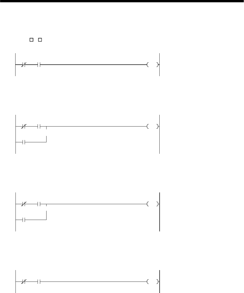
15 - 46
15. ABSOLUTE POSITION DETECTION SYSTEM
(e) Electromagnetic brake output
During ABS data transfer (for several seconds after the servo-on (SON) is turned on), the servo
motor must be at a stop.
Set "1 1 " in parameter No. 1 of the servo amplifier to choose the electromagnetic brake interlock
(MBR).
Y1 X1
Y4 Electromagnetic brake output
ABS transfer
mode Brake (MBR)
(f) Positioning completion
To create the status information for servo positioning completion.
During ABS data transfer (for several seconds after the servo-on (SON) is turned on), the servo
motor must be at a stop.
Y1 X0
M
Y1
Completion of servo positioning
ABS transfer
mode Positioning
completion
ABS transfer
mode
(g) Zero speed
To create the status information for servo zero speed.
During ABS data transfer (for several seconds after the servo-on (SON) is turned on), the servo
motor must be at a stop.
Y1 X1
M
Y1
Servo zero speed
ABS transfer
mode Zero speed
ABS transfer
mode
(h) Torque limiting
To create the status information for the servo torque limiting mode.
During ABS data transfer (for several seconds after the servo-on (SON) is turned on), the torque
limiting must be off.
Y1 X2
MServo torque limiting mode
ABS transfer
mode Torque limiting mode
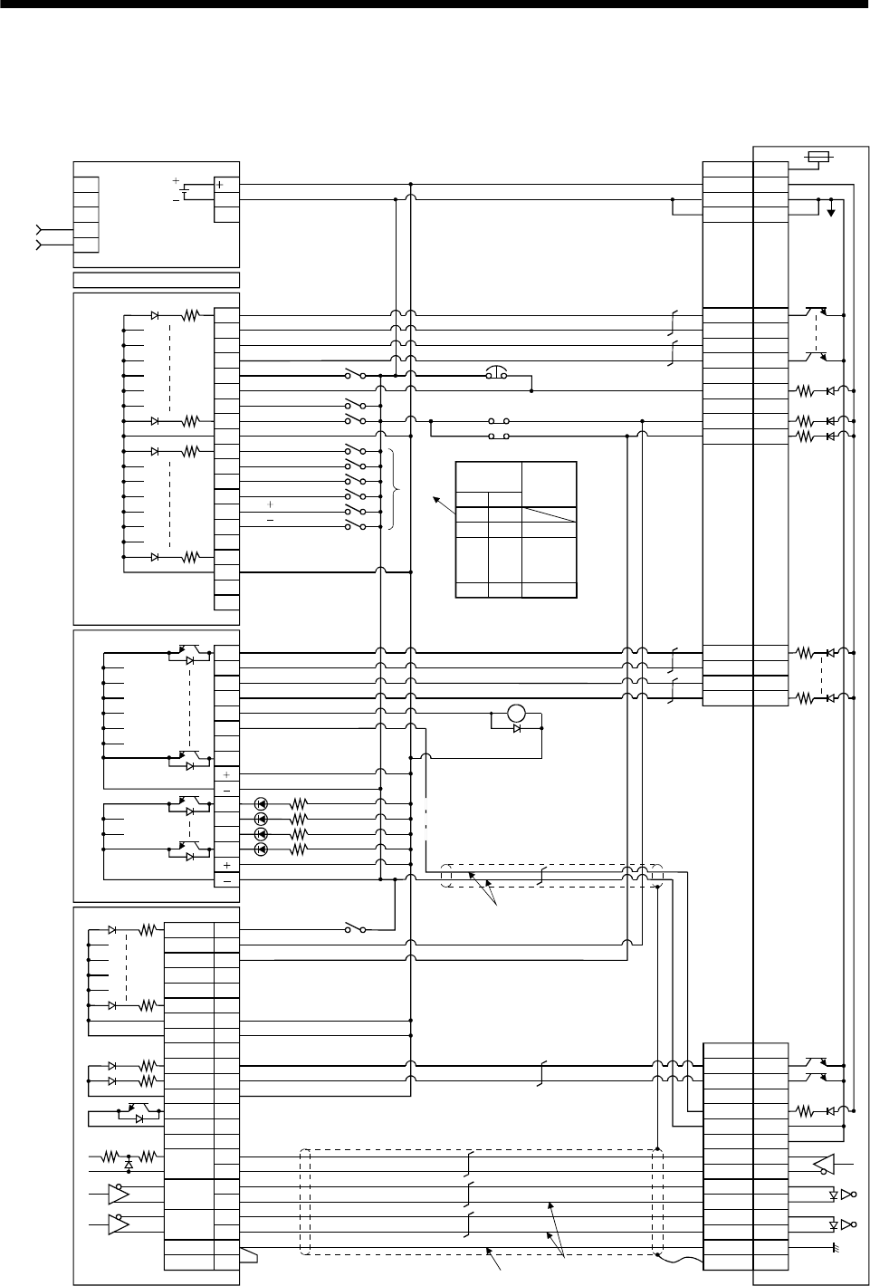
15 - 47
15. ABSOLUTE POSITION DETECTION SYSTEM
15.8.3 MELSEC A1SD75
(1) Connection diagram
PULSE-
R
PULSE-
F
PGO
DOG
STOP
RDY
4
22
3
21
25
24
7
14
11
0
1
2
3
4
5
7
COM
8
9
A
B
C
D
E
F
COM
NC
NC
6
0
1
2
3
4
5
7
6
8
9
A
B
A1SD75-P
A1SY40
A1SX40
A1SCPU
A1S62P
Power
supply INPUT
AC100/200
COM1
COM2
PLS 12
RLS 13
CHG 15
START 16
35
36
INPS 8
26
5CLEAR 23
PLS COM 19
PLS COM 20 SD
LG
NP
NG
PP
PG
LZR
LZ
SG
COM
RD
INP
CR
SG
9
19
18
8
10
20
5
15
13
3
12
2
1
Plate
5
8
9
14RES
ABSR
SON
ABSM
4
19
6
18ALM
15EMG
16LSP 17LSN
3
13
10
20SG
SG
VDD
COM
24
24G
FGLG
Servo amplifier
CN1B
CN1A
JOG
JOG
Alarm reset
Emergency stop
Servo-on
Home position return
Operation mode I
Operation mode II
Position start
Position stop
DO1
ABS data bit 1/zero speed
Readying to send data/Torque limiting
Trouble
Upper limit
Lower limit
ZSP
TLC
III
OFF OFF
OFF ON
ON OFF
ON ON
JOG
(Note 3)
Operation
mode Operating
status
Home
position
return
Positioning
Servo-on
ABS transfer mode
ABS request
Alarm reset
Electromagnetic
brake output
(Note 4)
Servo alarm
ABS communication error
ABS checksum error
(Note 2)
(Note 1)
Proximity signal
ABS data bit 0/Positioning completion
Servo ready
Positioning completion
COMMON
COMMON
COMMON
COMMON
(Note 2)
(Note 6) (Note 5)
600mA
RA2
(Note 6)

15 - 48
15. ABSOLUTE POSITION DETECTION SYSTEM
Note 1. For the dog type home position return. Need not be connected for the data set type home position return.
2. If the servo motor provided with the zero point signal is started, the A1SD75 will output the deviation counter clear (CR). Therefore,
do not connect the clear (CR) of the MR-J2-A to the A1SD75 but connect it to the output module of the programmable controller.
3. This circuit is provided for your reference.
4. The electromagnetic brake output should be controlled via a relay connected to the programmable controller output.
5. Use the differential line driver system for pulse input. Do not use the open collector system.
6. To reinforce noise suppression, connect LG and pulse output COM.
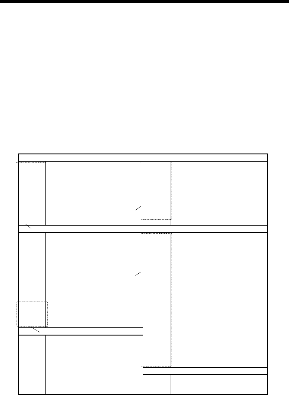
15 - 49
15. ABSOLUTE POSITION DETECTION SYSTEM
(2) Sequence program example
(a) Conditions
1) When the servo-on signal and power supply GND are shorted, the ABS data is transmitted at
power-on of the servo amplifier or on the leading edge of the RUN signal after a PC reset
operation (PC-RESET). The ABS data is also transmitted when an alarm is reset or when an
emergency stop is reset.
2) If a checksum mismatch is detected in the transmitted data, data transmission is retried up to
three times. If the checksum mismatch still persists after the retries, the ABS checksum error
occurs (Y3A ON).
3) The following time periods are measured. If the ON/OFF state does not change within the
specified time, the ABS communication error occurs change within the specified time, the ABS
communication error occurs (Y39 ON):
ON period of ABS transfer mode (Y31)
ON period of ABS request (Y32)
OFF period of reading to send ABS data (X22)
(b) Device list
X input contact Y output contact
X20 ABS bit 0 / positioning completion Y30 Servo-on
X21 ABS bit 1 / zero speed Y31 ABS transfer mode
X22 Reading to send ABS data / limiting torque Y32 ABS request
X23 Servo alarm Y33 Alarm reset
X24 Alarm reset X34 (Note 2) Electromagnetic brake output
X25 Servo emergency stop Y35 (Note 1) Clear
X26 Servo-on Y38 Servo alarm
X27 Home position return start Y39 ABS communication error
X28 Operation mode I Y3A ABS checksum error
X29 Operation mode II
D register M contact
D0 ABS data transmission counter M5 ABS data transmission start
D1 Checksum transmission counter M6 Sum check completion
D2 Checksum addition register M7 Sum check mismatch
D3 ABS data: Lower 16 bits M8 ABS data ready
D4 ABS data: Upper 16 bits M9 Transmission data read enabled
D5 ABS data 2-bit receiving buffer M10 Checksum 2 bits read completion
D6 Check data in case of checksum error M11 ABS 2 bits read completion
D7 Number of retries M12 ABS 2 bits request
D8 Forward rotation direction M13 Servo-on request
D9 Home position address: Lower 16 bits M14 Servo alarm
D10 Home position address: Upper 16 bits M15 ABS data transmission retry start pulse
D11 Drive unit ready data M16 Retry flag set
D12 Home position return completion data M17 Retry flag reset
D110 Received shift data: Lower 16 bits M18 PLS processing command
D111 Received shift data: Upper 16 bits M20 (Note 1) Clear (CR) ON timer request
T timer M21 (Note 1) Data set type home position return request
T0 ABS transmission mode timer
T1 ABS request response timer M22 Home position return processing
instruction
T2 Retry wait timer
T3 ABS data send reading response timer M23 Current position change processing
instruction
T10 (Note 1) Clear (CR) ON timer M24 Current position change flag
T200 Transmitted data read 10ms delay timer C counter
C0 ABS data receive times counter
C1 Checksum receive times counter
C2 Retry counter
Note 1. Required for data set type home position return.
2. Required for electromagnetic brake output.
3)
1)
2)
4)
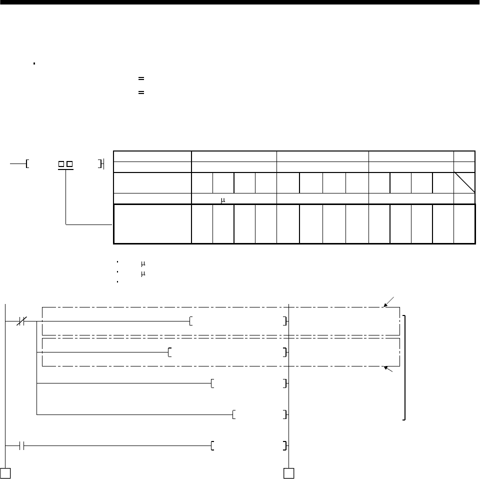
15 - 50
15. ABSOLUTE POSITION DETECTION SYSTEM
(c) ABS data transfer program for X axis
This sequence program example assumes the following conditions:
Parameters of the A1SD75-P1 positioning module
1) Unit setting :3 pulse (PLS)
2) Travel per pulse :1 1 pulse
To select the unit other than the pulse, conversion into the unit of the feed value per pulse is
required. Hence, add the following program to the area marked (Note) in the sequence program:
<Additional program> Item mm inch degree pulse
Unit setting 0 1 2 3
Travel per pulse 0.1 to 1 to 10 to 100 0.00001
to 0.0001
to 0.001
to 0.01
to 0.00001
to
0.0001
to 0.001
to 0.01
to
Unit of travel m/PLS inch/PLS degree/PLS PLS
D * P K D3 D3
Constant K for
conversion into unit of
travel 1 to 10 to 100
to 1000 1 to 10 to 100 to 1000 1 to 10 to 100
to 1000 None
Reference
For 1 m/PLS, set constant K to 10
For 5 m/PLS, set constant K to 50
The additional program is not required for the unit setting is PLS.
M101
Y30K3K0MOV
M9039
K1K1K1151H0000TO
D7K3MOV
M101SET
A0D110DMOV
1 1
6)
5)
Initial
setting
Output signal reset
A1SD75 error reset
Setting the number of retries
(to 3 times)
Error reset completion flag
Loading received shift data
(To be continued)
Error reset
completion
PC RUN
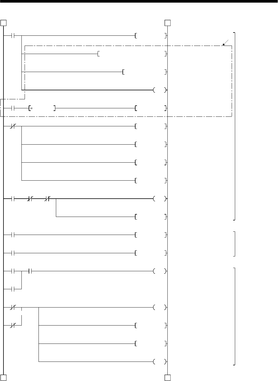
15 - 51
15. ABSOLUTE POSITION DETECTION SYSTEM
X26
M13SET
M23
K1D11K816H0000FROM
D11H0001WAND
M23
1 1
2 2
D11 K1 M24PLS
M13 M14 M16
X26
M8RST
M13RST
C0RST
C1RST
Y30
M5PLS
M13
M17PLS
M17
X24 M14
Y33
X25
Y33
X23
C2RST
M14
M8RST
M13RST
Y38
7)
Servo-on
control
ABS transfer
retry control
Servo alarm
detection,
alarm reset
control
Servo-on request
Reading A1SD75 1-axis RDY
signal
Masking RDY signal
Current position change
processing instruction
Current position change flag
Resetting ready
Resetting servo-on request
Resetting ABS transmission
counter at servo OFF
Resetting checksum
transmission counter at servo
OFF
Servo-on output
ABS interface start
Setting retry flag
Resetting retry counter
Alarm reset output
Error flag output
Resetting ready
Resetting servo-on request
Servo alarm
(To be continued)
(Continued from preceding page)
Servo-on
PB
Processing instruction RDY signal ON judgment
Servo-on
PB
Servo-on
request Error
flag Retry flag
set
Servo-on
request
Retry flag
reset request
Error reset
PB Error flag
Alarm reset
Emergency stop PB
Servo alarm
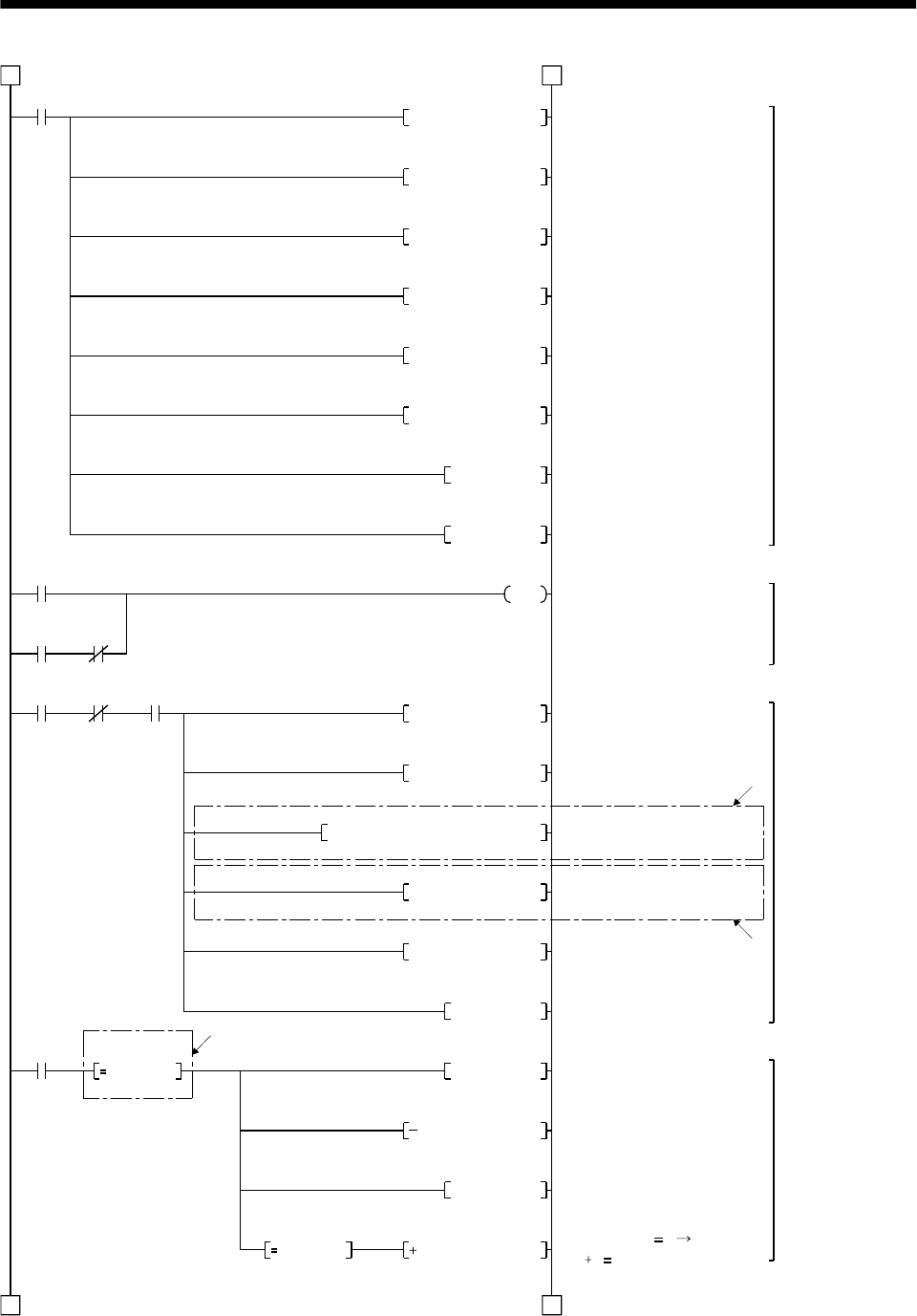
15 - 52
15. ABSOLUTE POSITION DETECTION SYSTEM
M5
D0K16MOV
M5
Y31 C1
2 2
3 3
D1K3MOV
D2 K0MOV
D5K0MOV
D9K0DMOV
A0K0DMOV
C0RST
C1RST
Y31
8)
C0 C1 Y31
D3A0DMOVP
K1D8K5H0000FROMP
M18PLS
M18
A0K0MOVP
D8H0001WAND
A1H8000WAND
D4NEG
D4K1
D3NEG
D4K1
D8 K1
K0 D3
9)
10)
Initializing ABS data
transmission counter
Initializing checksum
transmission counter
Initializing checksum register
Initializing ABS data register
Initializing ABS data register
Initializing ABS data register
Resetting ABS transmission
counter
Resetting checksum
transmission counter
ABS transfer mode
Saving ABS 32-bit data
Clearing register
*1 Reading x-axis rotation
direction parameter
Masking rotation direction
parameter
Masking ABS data sign
PLS processing command
Reversing polarity of upper
16 bits
Decrementing upper 16 bits
by 1
Reversing polarity of lower
16 bits
Lower 16 bits 0
D4 1 D4
ABS transfer mode
initial setting
ABS transfer mode
control
Absolute position
polarity,A1SD75
rotation direction
setting detection
Reversing absolute
position polarity
(Continued from preceding page)
(To be continued)
ABS data
transfer
start
ABS data
transfer start
ABS transfer
mode Checksum counter
Counter Sum
counter ABS transfer
mode
PLS
processing
command
Rotation direction
judgment
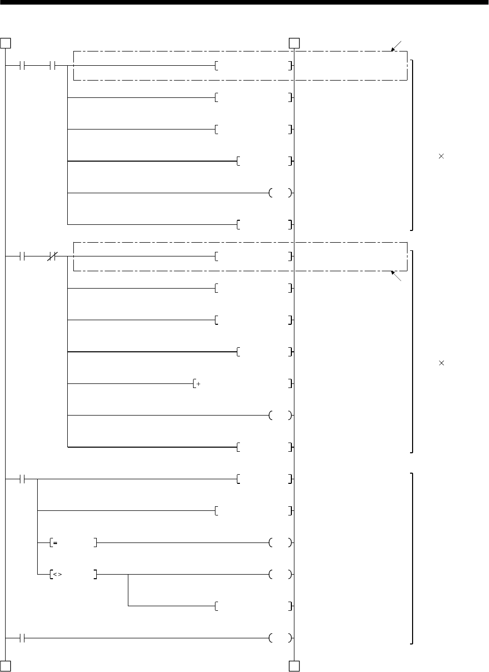
15 - 53
15. ABSOLUTE POSITION DETECTION SYSTEM
M9 C0
C1
3 3
4 4
D5K1X20MOV
D5H0003WAND
A0D5WOR
K2ROR
M10PLS
D1
M9 C0
D5K1X20MOV
K2DROR
D2D2D5
C0
C1
C2
D5H0003WAND
A0D5WOR
D0
M11PLS
K10RORP
A0H003FWAND
M6
M7
D6A0MOV
Y3A
D2 A0
D2 A0
11)
11)
Reading checksum
6bits
(2 bits 3 times)
Reading ABS data
32 bits
(2 bits 16 times)
Detecting ABS
checksum error
Reading 4 bits
Masking 2 bits
Adding 2 bits
Right rotation of A0 2 bits
Counting the number of
checksum data
Completion of reading
checksum 2 bits
Reading 4 bits
Masking 2 bits
Adding 2 bits
Right rotation of A0 2 bits
Adding checksum
Counting the number of ABS
data
Completion of reading ABS
2 bits data
Right rotation of A0 10 bits
Masking sum check
Sum check OK
Sum check NG
Sum check memory
ABS checksum error
(Continued from preceding page)
(To be continued)
Read
enabled ABS data
counter
Read
enabled ABS data
counter
Checksum
counter
Retry counter
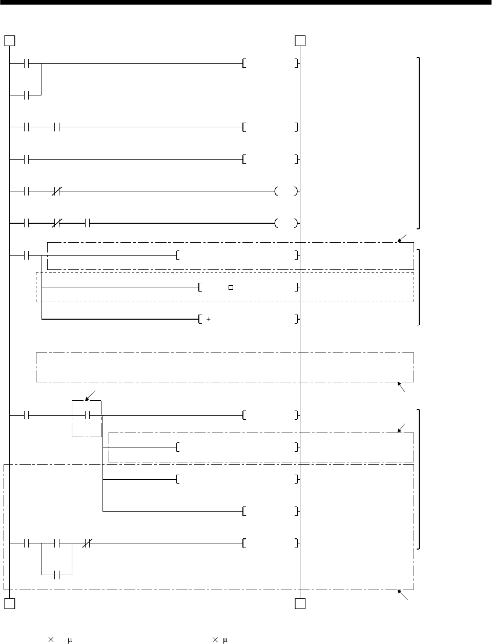
15 - 54
15. ABSOLUTE POSITION DETECTION SYSTEM
M11
M10
Y31 X22
M12
Y32 X22
Y32 X22 T200
4 4
5 5
Y32RST
M12PLS
Y32SET
T200
K1
M9
M6
K1D9K0072H0000DFROP
D3D3KD*P
D3D9D3D P
M6 M24
M8SET
K1D3K1154H0000DTOP
K1K9003K1150H0000TO
Y10SET
Y10 X1 X4
XA
Y10RST
12)
13)
15)
14)
7)
ABS request
control
Restoring absolute
position data.
Writing absolute
position data to
A1SD75
ABS request reset
ABS 2 bits request
ABS request set
10ms delay timer
Transmitted data read enabled
*1: Reading A1SD75 home
position address (Note2)
Inserting constant K for conversion
into the unit of feed per pulse
Adding home position address
to absolute position
ABS data ready
*1: Changing X-axis current
*1: Writing No. 9003 data for
Positioning start
Switching start signal off on
completion of positioning
(Continued from preceding page)
(To be continued)
ABS 2 bits
completion
Checksum 2 bits completion
ABS transfer
mode Ready to send
ABS data
ABS 2 bits request
ABS request Ready to send ABS data
10ms delay timer
Checksum
OK
(Note1)
Checksum
OK Change
flag
Positioning
start Start com-
pletion BUSY
Error detection
Note1. When the unit setting parameter value of the A1SD75 positioning module is changed from "3" (pulse) to "0" (mm), the
unit is 0.1 m for the input value. To set the unit to 1 m, add this program to multiple the feed value by 10.
2. The home position address loaded from flash ROM of normal positioning module can be obtained.
For updating the home position address by the home position setting,
refer to (2)(f)Data set type home position return in this Section.
position
changing current value
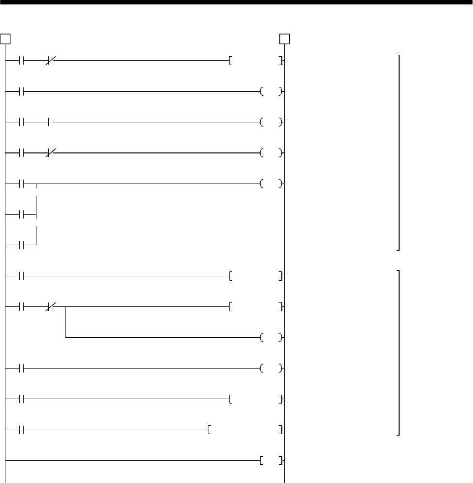
15 - 55
15. ABSOLUTE POSITION DETECTION SYSTEM
Y39 X26
Y31
T0
Y31 Y32
Y31 X22
T0
T1
T3
5 5
Y31RST
K50
T1
K10
T3
K10
Y39
M7
M15 C2
M16
T2
M9039
END
M15PLS
M16SET
C2
D7
T2
K1
M16RST
D110A0DMOV
Detecting ABS
communication
error
ABS transfer
retry control
Resetting ABS transfer mode
ABS transfer mode 5s timer
ABS request response
1s timer
ABS data send ready
response 1s timer
ABS communication error
ABS transfer retry start pulse
Setting retry flag
Retry counter
Retry waiting timer (100ms)
Resetting retry flag
Saving received shift data
ABS communi-
cation error Servo-on PB
(Continued from preceding page)
ABS transfer mode
ABS transfer
mode ABS request
ABS transfer
mode Ready to send
ABS data
ABS transfer NG
ABS request NG
Readying to send ABS data NG
Sum check NG
Retry start Retry
counter
Retry flag set
Retry waiting timer
PC RUN
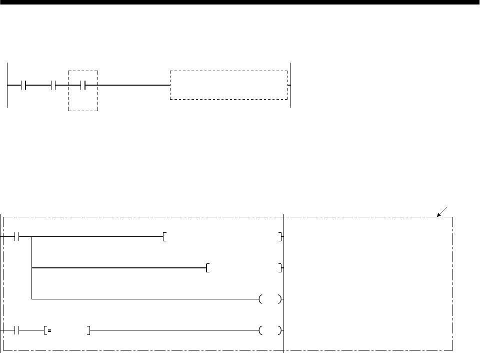
15 - 56
15. ABSOLUTE POSITION DETECTION SYSTEM
(d) X-axis program
Do not execute the X-axis program while the ABS ready (M8) is off.
M8 When "M8" (ready to send ABS data) switches on,
the X-axis start program is executed by the X-axis
start command.
X-axis start program
Positioning
mode X-axis start
command
Ready to
send ABS
data
(Note)
(e) Dog type home position return
Refer to the home position return program in the A1SD75 User’s Manual.
Note that this program requires a program which outputs the clear (CR) (Y35) after completion of
home position return.
Add the following program:
K1D12K817H0000FROM
M22
D12K0016WAND
Y35D12 K16
M22
16
)
Reading 1-axis home position return
completion signal
Masking home position return completion
Home position return processing instruction
Switching clear (CR) on
Home position return
start command
Processing
instruction Home position return
completion judgment
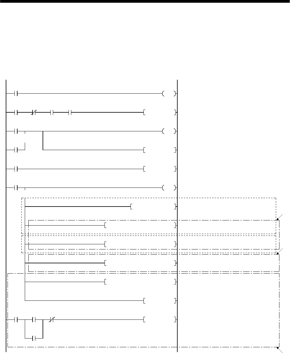
15 - 57
15. ABSOLUTE POSITION DETECTION SYSTEM
(f) Data set type home position return
After jogging the machine to the position where the home position (e.g. 500) is to be set, choose the
home position return mode and set the home position with the home position return start (PBON).
After switching power on, rotate the servo motor more than 1 revolution before starting home
position return.
Do not turn ON the clear (CR) (Y35) for an operation other than home position return. Turning it
on in other circumstances will cause position shift.
M9039
Y1D
Y31 X20 X27
M20
M21
T10
M20PLS
M21
D9K500DMOVP
K1D9K72H0000DTOP
K1D9K72H0000DFROP
K1D9K1154H0000DTOP
T10
M21SET
K1
M21RST
Y35
(Note 1)
(Note 2)
19)
18)
K1K9003K1150H0000TO
Y10SET
X1 X4Y10
Y10RST
XA
17)
Programmable controller ready
Clear (CR) ON timer request
Clear (CR) 100ms ON timer
Setting data set type home position return request
Resetting data set type home position return
request
Switch clear (CR) on
Setting X-axis home position address 500
in data register
*1: Changing X-axis home position address
(Note3)
*1: Changing X-axis current value
*1: Writing positioning data No. 9003
Starting positioning
Switching BUSY signal off to switch start
signal off.
PC RUN
Home position
return mode
ABS transfer
mode Positioning
completion Home position
return start PB
Clear signal ON
timer request
Data set type home position return request
Clear signal 100ms ON timer
Data set type home position
return request
Positioning
start Start
completion BUSY
Error detection
Note 1. If the data of the home position address parameter is not written from the A7PHP programming tool or the like
before starting the data set type home position return program, this sequence circuit (Note 1) is required and
the sequence circuit (Note 2) is not required.
2. Contrary to above 2, if the home position address is written in the home position address parameter,
the sequence circuit (Note1) is not required but this sequence circuit (Note 1) is required.
3. Changes are stored temporarily to buffer memory at this time. An additional processing is required
when changes should be reflected to memory for OS or flash ROM. For details, refer to the positioningmodule user's manual.
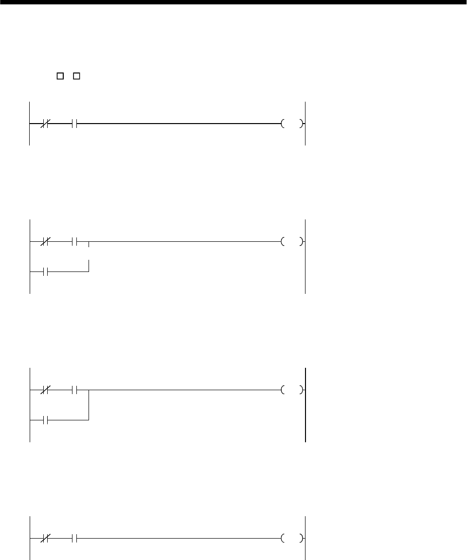
15 - 58
15. ABSOLUTE POSITION DETECTION SYSTEM
(g) Electromagnetic brake output
During ABS data transfer (for several seconds after the servo-on (SON) is turned on), the servo
motor must be at a stop.
Set "1 1 " in parameter No. 1 of the servo amplifier to choose the electromagnetic brake interlock
(MBR).
Y31 X21
Y34 Electromagnetic brake output
ABS transfer
mode Brake (MBR)
(h) Positioning completion
To create the status information for servo positioning completion.
During ABS data transfer (for several seconds after the servo-on (SON) is turned on), the servo
motor must be at a stop.
Y31 X20
M
Y31
Servo positioning completion
ABS transfer
mode Positioning
completion
ABS transfer
mode
(i) Zero speed
To create the status information for servo zero speed.
During ABS data transfer (for several seconds after the servo-on (SON) is turned on), the servo
motor must be at a stop.
Y31 X21
M
Y31
Servo zero speed
ABS transfer
mode Zero
speed
ABS transfer
mode
(j) Torque limiting
To create the status information for the servo torque limiting mode.
During ABS data transfer (for several seconds after the servo-on (SON) is turned on), the torque
limiting must be off.
Y31 X22
MServo torque limiting mode
ABS transfer
mode Torque limiting
mode
15 - 59
15. ABSOLUTE POSITION DETECTION SYSTEM
(3) Sequence program - 2-axis control
The following program is a reference example for creation of an ABS sequence program for the second
axis (Y axis) using a single A1SD75 module. Create a program for the third axis in a similar manner.
(a) Y-axis program
Refer to the X-axis ABS sequence program and create the Y-axis program.
Assign the X inputs, Y outputs, D registers, M contacts, T timers and C counters of the Y axis so
that they do not overlap those of the X axis.
The buffer memory addresses of the A1SD75 differ between the X and Y axes. The instructions
marked *1 in the program of Section 15.8.3 (2), (c) should be changed as indicated below for use
with the Y axis:
20)
X-axis ABS sequence program
(Program in Section 15.8.3 (2) (c))
Y-axis ABS sequence program
(Refer to the X-axis program and write the Y-axis
program)
[Program configuration]
[FROMP H0000 K5 D8 K1] [FROMP H0000 K155 D8 K1]
[DFROP H0000 K0072 D9 K1] [DFROP H0000 K222 D9 K1]
[DTOP H0000 K1154 D3 K1] [DTOP H0000 K1204 D3 K1]
[TO H0000 K1150 K9003 K1] [TO H0000 K1200 K9003 K1]
(b) Data set type home position return
Arrange the data set type home position return programs given in Section 15.8.3 (2), (f) in series to
control two axes.
Refer to the X-axis data set type home position return program and create the Y-axis program.
Assign the X inputs, Y outputs, D registers, M contacts and T timers of the Y axis so that they do
not overlap those of the X axis.
The buffer memory addresses of the A1SD75 differ between the X and Y axes. The instructions
marked *1 in the program of Section 15.8.3 (2), (f) should be changed as indicated below for use
with the Y axis:
20
)
X-axis data set type home position return program
(Program in Section 15.8.3 (2) (f))
Y-axis data set type home position return program
(Refer to the X-axis program and write the Y-axis
program)
[Program configuration]
[DTOP H0000 K72 D9 K1]
[DTOP H0000 K1154 D9 K1] [DTOP H0000 K1204 D3 K1]
[TO H0000 K1150 K9003 K1] [TO H0000 K1200 K9003 K1]
[DTOP H0000 K222 D9 K1]

15 - 60
15. ABSOLUTE POSITION DETECTION SYSTEM
(4) Differences between A1SD75 and A1SD71
The sequence programs shown in (2) of this section differ from those for the A1SD71 in the following
portions. 1) to 20) in the following sentences indicate the numbers in the programs given in (2) of this
section.
(a) Devices used
Since the A1SD75 is a one-slot module which occupies 32 I/O points, the I/O devices are different,
as indicated by 1) and 2), from those of the two-slot A1SD71 which occupies 48 point. The A1SD75
uses the devices indicated in the following table, and its D registers and M contacts are different as
indicated by 3) and 4).
Devices
Device name Axis 1 Axis 2 Axis 3 Application Bit device :Data at ON
Data register :Stored data
X0 A1SD75 ready Not ready/ WDT error
X4 X5 X6 BUSY BUSY(running)
Input XA XB XC Error detection Error detection
Y10 Y11 Y12 Positioning start Start being requested
Y13 Y14 Y1C Axis stop Stop being requested
Y16 Y18 Y1A Forward rotation jog start Forward rotation being started
Y17 Y19 Y1B Reverse rotation jog start Reverse rotation being started
Output
Y1D Programmable controller ready Programmable controller CPU
normal
M0 Parameter setting completion flag Setting complete
M1 Flash ROM registration processing
flag Processing
M2 M3 M4 Axis error reset requesting flag Requesting
M100 A1SD75 normal flag A1SD75 normal
M101 Initial error reset completion flag Error reset complete
M102 All BUSY signal OFF flag All BUSY signal OFF
internal relay
M103 A1SD75 operable flag Operable
D100 Flash ROM registration results Registration results
D101 D102 D103 Axis error code Error code
D104 D105 D106 Axis warning code Warning code
Data register
D107 D108 D109 Axis error reset results Axis error reset results
(b) ABS sequence program example
1) Initial setting
To reset the error of the A1SD75, the program 5) is added to reset all output signals at start-up.
The axis error reset buffer memory address is changed from 201 to 1154 (axis 1) and the slot
number from H0001 (slot number 1) to H0000 (slot number 2) 6).
2) Absolute position polarity, A1SD75 rotation direction setting detection
The slot number and buffer memory of the X-axis rotation direction parameter reading area are
changed from [FROMP H0001 K7872 D8 K1] to [FROMP H0000 K5 D8 K1] 8).
The rotation direction parameter masking area is changed from [WAND H0004 D8] to [WAND
H0001 D8] 9).
3) Reversing absolute position polarity
The rotation direction judging area is changed from [= D8 K4] to [= D8 K1] 10).
4) Reading checksum 6 bits, reading ABS data 32 bits
The 4 bits reading area is changed from [MOV K1 X30D5] to [MOV K1X20 D5] 11).
5) Restoring absolute position data
The slot number and buffer address of the A1SD75 home position address reading area are
changed from [DFROP H0001 K7912 D9 K1] to [DFROP H0000 K72 D9 K1] 12)

15 - 61
15. ABSOLUTE POSITION DETECTION SYSTEM
6) Writing absolute position data to A1SD75
The slot number and buffer address of the X-axis current value changing area are changed from
[DTOP H0001 K41 D3 K1] to [DTOP H0000 K1154 D3 K1] 14). When the current value is changed
in the A1SD75, the current feed value is changed at the start of positioning data No.9003.
Therefore, the starting program for positioning data No.9003 15) is added.
7) X-axis data set type home position return program
The slot numbers and buffer addresses of the X-axis home position address changing area are
changed from [DTOP H0001 K7912 D9 K1] to [DTOP H0000 K72 D9 K1] and from [DFROP
H0001 K7912 D9 K1] to [DFROP H0000 K72 D9 K1] 17).
The slot number and buffer address of the X-axis current value changing area are changed from
[DTOP H0001 K41 D3 K1] to [DTOP H0000 K1154 D3 K1] 18). When the current value is changed
in the A1SD75, the current feed value is changed at the start of positioning data No.9003.
Therefore, the starting program for positioning data No.9003 19) is added.
8) Y-axis sequence program, Y-axis data set type home position return program.
The slot numbers and buffer addresses are changed as indicated by 20).
9) Writing absolute position data to A1SD75
The A1SD75 allows the current position to be changed only when the ready (RD) of the Servo
amplifier is on. Therefore, if the CPU scan is fast, the program for A1SD71 may change the
current position before the ready (RD) switches on. 7) is added because the current position must
be changed after it has been confirmed that the drive unit ready (RD) of the A1SD75 (D75) has
switched on/off.
10) ABS coordinate error detection
As the A1SD75 can handle the negative-polarity coordinate position that the A1SD71 could
not handle, the program for ABS coordinate error detection is deleted. 13)
11) Dog type home position return program
Due to the changes in wiring described in (4), (a), 4) of this section, the program for
outputting the clear (CR) (Y35) after completion of a home position return is required. 16)
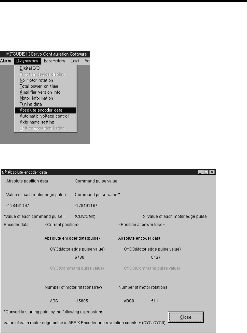
15 - 62
15. ABSOLUTE POSITION DETECTION SYSTEM
15.9 Confirmation of absolute position detection data
You can confirm the absolute position data with MR Configurator (servo configuration software).
Crick "Diagnostics" and "Absolute Encoder Data" to open the absolute position data display screen.
(1) Cricking "Diagnostics" in the menu opens the sub-menu as shown below:
(2) By cricking "Absolute Encoder Data" in the sub-menu, the absolute encoder data display window
appears.
(3) Crick the "Close" button to close the absolute encoder data display window.

15 - 63
15. ABSOLUTE POSITION DETECTION SYSTEM
15.10 Absolute position data transfer errors
15.10.1 Corrective actions
(1) Error list
The number within parentheses in the table indicates the output coil or input contact number of the
A1SD71.
Output coil
Name AD71 1PG Description Cause Action
1. Wiring for ABS transfer mode
signal, ABS data request
signal, or ready to send signal
is disconnected or connected to
the SG terminal.
Correct the wiring.
2. PC ladder program wrong. Correct the ladder.
3. Faulty PLC output or input
module. Change the input or output
module.
4. Faulty printed board in the
servo amplifier. Change the amplifier
(Note)
ABS
communication
error
Y49 Y11 1. The ABS data transfer mode
signal (Y41) is not completed
within 5s.
2. The ready to send signal
(X32) is not turned OFF
within 1s after the ABS data
request signal (Y42) is turned
ON.
3. The ready to send signal
(X32) remains OFF for longer
than 1s. 5. Power supply to the servo
amplifier is OFF. Turn on the power to the servo
amplifier.
1. Wiring for the ABS data
signal (ABS bit 0 (PF), bit 1
(ZSP)) is disconnected or
connected to the SG terminal.
Correct the wiring.
2. PC ladder program wrong. Correct the ladder.
3. Faulty PLC input module. Change the input module.
ABS data
check sum
error
Y4A Y12 ABS data sumcheck resulted
in mismatch four times
consecutively.
4. Faulty printed board in the
servo amplifier. Change the amplifier.
1. The servo is turned ON or the
power supply is turned ON
near the machine home
position or in the zone in
which addresses decrease.
1. Reconsider the position
where the servo is turned
ON.
2. Set the home position for
positioning apart from the
machine home position.
ABS
coordinate
error
Y4B The motor position is in the
negative coordinate value
range when the servo is
turned ON or when power
supply is turned ON.
2. The machine falls on a
vertical axis when the servo-
on (SON) is turned ON/OFF.
Change the electromagnetic
brake operation sequence.
1. Emergency stop (EMG) of the
servo amplifier was turned
off.
After ensuring safety, turn
EMG on.
Servo alarm Y48 Y10 Alarm occurred in the servo
amplifier.
2. Trouble (ALM) of the servo
amplifier was turned on. Refer to Section 10.2.2 and take
action.
Note. Refer to (2) in this section for details of error occurrence definitions.
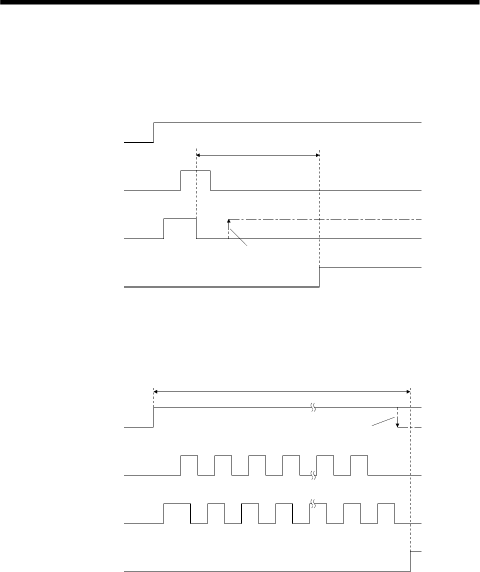
15 - 64
15. ABSOLUTE POSITION DETECTION SYSTEM
(2) ABS communication error
(a) The OFF period of the send data ready signal output from the servo amplifier is checked.
If the OFF period is 1s or longer, this is regarded as a transfer fault and the ABS communication
error is generated.
The ABS communication error occurs if the ABS time-out warning (AL.E5) is generated at the
servo amplifier due to an ABS request ON time time-out.
OFF
ON
OFF
ON
OFF
ON
1s
A
BS transfer mode
A
BS request
S
end data ready
A
BS communication
e
rror
The signal does not come ON
NO
YES
(b) The time required for the ABS transfer mode signal to go OFF after it has been turned ON (ABS
transfer time) is checked.
If the ABS transfer time is longer than 5s, this is communication error occurs if the ABS time-out
warning (AL.E5) is generated at the servo amplifier due to an ABS transfer mode completion time
time-out.
OFF
ON
OFF
ON
OFF
ON
12341819
1 2 3 4 18 19
5s
A
BS transfer mode
A
BS request
Send data ready
A
BS communication
error
The signal does not go OFF
NO
YES
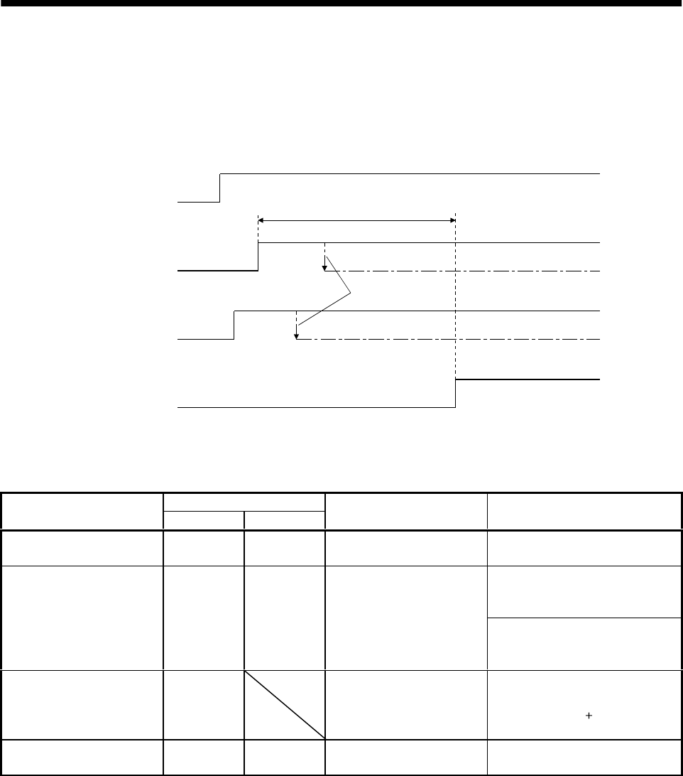
15 - 65
15. ABSOLUTE POSITION DETECTION SYSTEM
(c) To detect the ABS time-out warning (AL.E5) at the servo amplifier, the time required for the ABS
request signal to go OFF after it has been turned ON (ABS request time) is checked. If the ABS
request remains ON for longer than 1s, it is regarded that an fault relating to the ABS request
signal or the send data ready (TLC) has occurred, and the ABS communication error is generated.
The ABS communication error occurs if the ABS time-out warning (AL.E5) is generated at the
servo amplifier due to an ABS request OFF time time-out.
OFF
ON
OFF
ON
OFF
ON
1s
ABS transfer mode
ABS request
Send data ready
ABS communication
error
The signal does
not go OFF
NO
YES
15.10.2 Error resetting conditions
Always remove the cause of the error before resetting the error.
Output coil
Name AD71 1PG Servo status Resetting condition
ABS communication error Y49 Y11 Ready (RD) off Reset when servo-on (SON) PB
(X36) signal turns off.
For AD71
Reset when servo-on (SON) PB
(X36) signal turns from off to on.
ABS checksum error Y4A Y12 Ready (RD) on
For FX-1PG
Reset when servo-on (SON) PB
(X36) signal turns off.
ABS coordinate error Y4B Ready (RD) on Reset when servo-on (SON) PB
(X36) signal turns from off to on
after a motion to ( ) coordinate is
made by jog operation.
Servo alarm Y48 Y10 Ready (RD) on Reset when alarm reset PB turns
on or power switches from off to on.

15 - 66
15. ABSOLUTE POSITION DETECTION SYSTEM
MEMO
App - 1
App
endix
App 1. Signal arrangement recording sheets
(1) Position control mode
1
2
3
5
4
6
7
9
8
10
11
12
13
14
15
16
17
18
19
20
DO1
LG
VDD
SG
P15R
COM
1
2
3
5
4
6
7
9
8
10
11
12
13
14
15
16
17
18
19
20
COM
OPC
SG
NG
SGSG
CN1A CN1B
LB
LAR
LA
LZR
LZ
OP
P15R
PGPP
NP
LG
LBR
EMG
LSP
TLA
LSN
(2) Speed control mode
1
2
3
5
4
6
7
9
8
10
11
12
13
14
15
16
17
18
19
20
DO1
LG
VDD
SG
P15R
COM
1
2
3
5
4
6
7
9
8
10
11
12
13
14
15
16
17
18
19
20
COM
SG
SGSG
CN1A CN1B
LB
LAR
LA
LZR
LZ
OP
P15R
LBR
EMG
LSP
LSN
LG
VC
(3) Torque control mode
1
2
3
5
4
6
7
9
8
10
11
12
13
14
15
16
17
18
19
20
DO1
LG
VDD
SG
P15R
COM
1
2
3
5
4
6
7
9
8
10
11
12
13
14
15
16
17
18
19
20
COM
SG
SGSG
CN1A CN1B
LB
LAR
LA
LZR
LZ
OP
P15R
LBR
EMG
LG
VLA TC
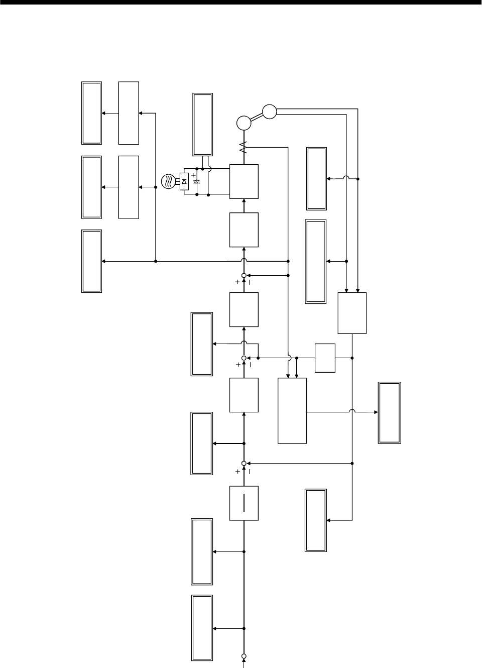
App - 2
Appendix
App 2. Status display block diagram
Effective
load ratio
Effective
value calculation
Instantaneous
torque Peak
load ratio
Peak hold
PWM M
Current
control
Speed
control
Servo
motor speed
Position
control
Droop pulse
Present
position
calculation
ABS counter
Within one-
revolution position low
high
Load inertia
moment ratio
Auto
tuning section
Cumulative
feedback pulse
Cumulative
command pulses
CMX
CDV
Differ-
ential
Command
pulse frequency
Electronic gear
Bus voltage
PP, NP
Speed
feedback
Within
one-revolution
ABS counter
C
ommand
pulse
Servo
motor
Absolute
position
detection
encoder

App - 3
Appendix
App 3. Combination of servo amplifier and servo motor
The servo amplifier software versions compatible with the servo motors are indicated in the parentheses.
The servo amplifiers whose software versions are not indicated can be used regardless of the versions.
Servo motor Servo amplifier
(Software version) Servo motor Servo amplifier
(Software version)
HC-RFS103 MR-J2S-200A
HC-KFS053 MR-J2S-10A
MR-J2S-10A1 HC-RFS153 MR-J2S-200A
HC-RFS203 MR-J2S-350A (Version B0 or later)
HC-KFS13 MR-J2S-10A
MR-J2S-10A1 HC-RFS353 MR-J2S-500A (Version B0 or later)
HC-RFS503 MR-J2S-500A (Version B0 or later)
HC-KFS23 MR-J2S-20A
MR-J2S-20A1 HC-UFS72 MR-J2S-70A
HC-UFS152 MR-J2S-200A
HC-KFS43 MR-J2S-40A
MR-J2S-40A1 HC-UFS202 MR-J2S-350A (Version B0 or later)
HC-KFS73 MR-J2S-70A (Version A4 or later) HC-UFS352 MR-J2S-500A (Version B0 or later)
HC-UFS502 MR-J2S-500A (Version B0 or later)
HC-MFS053 MR-J2S-10A
MR-J2S-10A1 HC-UFS13 MR-J2S-10A
MR-J2S-10A1
HC-MFS13 MR-J2S-10A
MR-J2S-10A1 HC-UFS23 MR-J2S-20A
MR-J2S-20A1
HC-MFS23 MR-J2S-20A
MR-J2S-20A1 HC-UFS43 MR-J2S-40A
MR-J2S-40A1
HC-MFS43 MR-J2S-40A
MR-J2S-40A1 HC-UFS73 MR-J2S-70A
HC-MFS73 MR-J2S-70A HC-LFS52 MR-J2S-60A (Version B3 or later)
HC-SFS81 MR-J2S-100A (Version A1 or later) HC-LFS102 MR-J2S-100A (Version B3 or later)
HC-SFS121 MR-J2S-200A (Version A1 or later) HC-LFS152 MR-J2S-200A (Version B3 or later)
HC-SFS201 MR-J2S-200A (Version A1 or later) HC-LFS202 MR-J2S-350A (Version B3 or later)
HC-SFS301 MR-J2S-350A (Version A1 or later) HC-LFS302 MR-J2S-500A (Version B3 or later)
HC-SFS52 MR-J2S-60A HA-LFS801 MR-J2S-11KA
HC-SFS102 MR-J2S-100 HA-LFS12K1 MR-J2S-11KA
HC-SFS152 MR-J2S-200A HA-LFS15K1 MR-J2S-15KA
HC-SFS202 MR-J2S-200A HA-LFS20K1 MR-J2S-22KA
HC-SFS352 MR-J2S-350A HA-LFS25K1 MR-J2S-22KA
HC-SFS502 MR-J2S-500A (Version B0 or later) HA-LFS11K1M MR-J2S-11KA
HC-SFS702 MR-J2S-700A (Version B0 or later) HA-LFS15K1M MR-J2S-15KA
HC-SFS53 MR-J2S-60A (Version A1 or later) HA-LFS502 MR-J2S-500A (Version B0 or later)
HC-SFS103 MR-J2S-100A (Version A1 or later) HA-LFS702 MR-J2S-700A (Version B0 or later)
HC-SFS153 MR-J2S-200A (Version A1 or later) HA-LFS11K2 MR-J2S-11KA
HC-SFS203 MR-J2S-200A (Version A1 or later) HA-LFS15K2 MR-J2S-15KA
HC-SFS353 MR-J2S-350A (Version A1 or later) HA-LFS22K2 MR-J2S-22KA

App - 4
Appendix
MEMO

REVISIONS
*The manual number is given on the bottom left of the back cover.
Print data *Manual number Revision
Nov.,1999 SH(NA)030006-A First edition
Sep.,2000 SH(NA)030006-B Addition of single-phase 100VAC specifications
Compatible Servo Configuration software model name change
Compliance with EC Directives 1: Review of sentence
Section 1.2: Review of function block diagram
Section 1.3: Moving of servo amplifier standard specifications
Review of torque limit description in position control mode
Review of torque limit description in speed control mode
Deletion of torque linearity in torque limit mode
Addition of speed limit in torque control mode
Section 3.1.1 (1): Addition of encoder Z-phase pulse connection
Addition of Note for use of junction terminal block
Section 3.1.1 (2): Addition of Note for increased noise immunity
Section 3.1.2: Addition of Note for input of negative voltage
Section 3.1.3: Addition of Note for input of negative voltage
Section 3.3.1 (2): Review of Note
Section 3.4.1 (4): Addition of description about electronic gear switching
Section 3.4.3 (1)(a): Review of description for low voltage
Section 3.5: Change in timing chart
Section 3.5 3): Review of description
Section 3.6.2 (7): Review of connection
Section 3.9: Review of POINT
Section 3.9 (3)(b),(c): Change in timing chart
Section 3.9 (3)(d),(e): Addition
Section 5.1.2 (2): Deletion of description as to parameter No. 22 TC, TLA
Addition of parameter No. 27 setting example
Correction of parameter No. 35 setting range
Review of parameter No. 47, 48 sentences
Section 5.2.5: Correction of operation pattern diagram
Section 6.2.2: Review of within one-revolution position sentence
Section 6.3: Review of automatic VC offset description
Section 6.6 (2)(a): Review of Note
Section 6.8: Review of PL sentence
Chapter 7: Addition of POINT
Section 7.3.2 (1), (2): Review of sentence makeup
Section 7.4: Addition
Section 8.1.1: Addition
Section 8.3.2: Addition
Section 10.1.1 (1): Addition of Investigation item at power-on
Section 10.1.2: Addition of Investigation item at power-on
Addition of Investigation item at on of ST1 or ST2
Section 10.1.3: Addition of Investigation item at power-on
Addition of Investigation item at on of ST1 or ST2
Section 10.2: Addition of POINT
Section 10.2.2: Review of Cause of AL.10
Deletion of Cause 4 of AL.16
Review of Cause and Action of AL.24
Addition of description to AL.25

Print data *Manual number Revision
Sep.,2000 SH(NA)030006-B Section 10.2.2: Addition of description to AL.30
Addition of Cause to AL.33
Chapter 11: Changed to only outline dimensional drawing
Section 11.2 (2): Addition
Section 12.2 (1): Review of Note for Table 12.1
Section 12.3: Correction of dynamic brake time constant graph
Chapter 13: Deletion of MR-CPC98CBL3M communication cable
Section 13.1.1 (4)(c): Review of outline drawing
Section 13.1.2 (1): Deletion of MR-PWCNF power supply connector set
Section 13.1.2 (1)1), 6): Change of encoder side connector models
Section 13.1.2 (1)19), 20): Change of terminal models
Section 13.1.2 (2)(a)2): Addition of description for fabrication
Section 13.1.3: Addition of POINT
Section 13.1.3 (4): Addition of cable length
Change in connection diagram
Section 13.2.1 (1): Addition of Note for recommended wires
Section 13.2.8 (1): Addition of leakage current to recommended filter
Section 14.1.2 (2): Deletion of MR-CPC98CBL3M communication cable
Section 14.11.1 (6): Addition
Section 14.11.2 (8): Addition
Section 15.7: Addition of POINT
Section 15.8.1 (1)(b): Change in b) Coordinates when zero address is changed
to other than 0
Section 15.8.2 (1)(b): Review of connection diagram
Section 15.9: Change of display screen
Section 15.10.1 (1): Deletion of Cause 5 of ABS checksum error
Feb.,2001 SH(NA)030006-C Addition of MR-J2S-500A, 700A servo amplifiers
Addition of HC-KFS73, HC-SFS502, HC-SFS702, HC-RFS353, HC-RFS503,
HC-UFS502, HC-UFS353 servo motors
Section 1.2: Function block diagram modification
Section 1.7: Overall reexamination
Section 3.7.1(2): Addition of single-phase 100 to 120VAC
Section 3.7.2: Addition of regenerative brake converter and brake unit
Section 5.1.2(2): No. 0, Item addition to regenerative brake option selection
No. 5, Example addition
No. 27, Setting range change
No. 49, AL.26 addition
Section 5.2.2: Overall reexamination
Section 7.4(1): Reexamination
Chapter 8: Hierarchy reexamination
Section 10.2.2: AL.30, Reexamination
AL.8E, Reexamination of Cause and Action
Section 11.1(4)(5): Addition
Section 11.2(3): Addition
Section 12.1(3): Addition
Chapter 13: Hierarchy reexamination
Section 13.1.4(1): Connection diagram change
Cable addition
Section 13.1.4(3): Reexamination
Section 13.2.1(1): Connection diagram change
Wire table addition
Chapter 15: Addition of Note on AL.25

Print data *Manual number Revision
Oct.,2002 SH(NA)030006-D Servo amplifier: Addition of MR-J2S-11KA, MR-J2S-15KA and MR-J2S-22KA
Servo motor: Addition of HA-LFS11K2, HA-LFS15K2, HA-LFS22K2 and
HC-LFS
SAFETY INSTRUCTIONS: Addition of About processing of waste
Addition of FOR MAXIMUM SAFETY
Addition of EEP-ROM life
Compliance with EC Directives 2: Addition of Note to (3)
Reexamination of sentences in (4)(a)
Conformance with UL/C-UL Standard: Addition of (6) Attachment of servo motor
Addition of (7) About wiring protection
Section 1.4: Change made to the contents of the test operation mode
Section 1.7.2 (4): Addition
Section 1.8 (5): Addition
Section 2.3 (3): Sentence change
Section 3.1.1 (1), (2): Addition of Note 14
Section 3.1.2: Addition of Note 14
Section 3.1.3: Addition of Note 12
Section 3.2: Addition of Note
Section 3.5: Addition of Note
Section 3.7: Addition of POINT
Section 3.8.2: Addition of POINT
Overall reexamination
Section 3.8.3: Addition of Note
Section 3.11: Overall reexamination
Section 3.13: Addition
Section 4.2.3: POINT sentence change
Section 4.2.4: POINT sentence change
Section 5.2 (2): Addition of regenerative brake option to parameter No. 0
Addition of CN1B-pin 19's function selection to parameter No. 1
Modification made to the contents of parameter No. 5
Reexamination of the contents of parameter No. 23
Addition of AL. 37-related sentences to parameter No. 49
Section 5.2.1 (3): Reexamination of some servo motor speeds
Section 5.2.2: Changed to analog monitor
Section 7.2.2: POINT sentences addition
Section 10.2.1: Sentence addition
Section 10.2.2: Addition of 4. to alarm 16
Addition of 3. to alarm 20
Addition of 6. to alarm 33
Changing of occurrence factor and checking method of alarm 50
Changing of occurrence factor and checking method of alarm 51
Section 11.2 (1): Overall change
Section 12.1 (4): Addition
Note sentence addition
Section 12.3: Note sentence addition
Section 13.1.1 (1): Regenerative brake option addition
Section 13.1.1 (3): Parameter setting addition
Section 13.1.1 (4): Reexamination
Section 13.1.1 (5): Outline drawing addition
Section 13.1.2: Addition of FR-BU-55K brake unit

Print data *Manual number Revision
Oct.,2002 SH(NA)030006-D Section 13.1.3: Addition of FR-BU-55K brake unit
Section 13.1.4: Addition
Section 13.1.5 (1): Configuration diagram reexamination
Note sentence addition
Addition of connector sets and monitor cables
Section 13.1.5 (2): POINT sentence addition
Section 13.1.9 (2)(a): Reexamination
Section 13.2.1 (1): Reexamination
Section 13.2.3: Reexamination
Section 13.2.4: Addition
Section 13.2.8 (1): Leakage current breaker addition
Section 13.2.9 (1): EMC filter addition
Section 14.1.2 (2): Personal computer connector corrected to D-SUB9
Section 14.11: Addition of POINT
Section 14.12.7 (2)(d): Addition
Jun., 2003 SH(NA)030006-E Safety Instructions 1. To prevent electric shock: Sentence addition
3. To prevent injury: Sentence addition
4. Additional instructions: Partial sentence change
COMPLIANCE WITH EC DIRECTIVES 2. (6) (a): Addition
Section 1.3: Inrush current addition
Section 3.6.2 (3) (a) 1): Partial figure change
Section 3.6.2 (3) (b) 1): Partial figure change
Section 3.8.3: Partial figure change
Section 3.13.3: Partial terminal box inside figure change
Section 4.2: CAUTION sentence addition
Section 5.1.2 (2): Parameter No. 0 Addition of (The built-in regenerative
brake resistor is used.) to "Regenerative
brake option is not used"
Addition of FR-CV to the setting of 01 in
Selection of regenerative brake option
Partial sentence deletion
Parameter No. 20 Addition of sentence to Slight vibration
suppression control
Section 5.2.1 (3): Servo amplifier, Electronic gear, 3000r/min changed to
2048/125
Servo amplifier, Electronic gear, 2000r/min changed to
4096/375
Section 6.4 (2): Sentence change
Section 6.6 (3) (a): In position LNP changed to INP
Section 10.2.1: Partial sentence change
Section 10.2.2: AL. 12 to 15 Contents reexamination
AL. 37 Addition of Cause 3
AL. 50 Partial contents change
AL. 51 Addition of "During rotation: 2.5s or more"
Section 12.3: Change of sentence that explains "te"
Section 12.5: Addition
Section 13.1.1 (4) (d): Partial connection diagram change
Section 13.1.2: Addition of "When using the brake unit, set "01 " in
parameter No. 0"
Section 13.1.3: Addition of "When using the power regeneration converter, set
"01 " in parameter No. 0"
Section 13.1.3 (2): Partial connection diagram change

Print data *Manual number Revision
Jun., 2003 SH(NA)030006-E Section 13.1.4 (2): Partial connection diagram change
Section 13.1.10: Addition
Section 13.2.1 (1): Correction of the AWG of the recommended wire 60mm2 to
2/0
Section 13.2.10 (2) (3): Correction of the position meter model name to
RRS10M202
Section 14.12.7 (2) (b): Addition of ST1 to the Forward rotation start data
Addition of ST1 to the Reverse rotation start data
Section 14.12.7 (3) (b): Servo-on Stroke end changed to ON
Section 15.4: Correction of the Command pulses of the positioning module to
differential line driver type
Oct., 2003 SH(NA)030006-F Reexamination of Servo Configuration software representation
Safety Instructions 3. To prevent injury: Reexamination of some sentences
COMPLIANCE WITH EC DIRECTIVES (3) (4): Change to IEC60664-1
Section 3.6.2 (7): Addition of explanation on JP11 in the case of 11kW or more
Section 5.1.2 (2): Reexamination of part of parameter No.20
Classification of automatic setting in Low-pass filter selection
of parameter No. 60 Reexamination of part of parameter No.
76 sentences
Section 5.2.1 (3): Addition of 103 to expression
Section 10.2.2: Addition of Definition, Cause and Action to AL.32
Section 12.5: Change of wiring length to 1m
Section 13.1.1 (4): Sentence reexamination
Section 13.1.1 (5) (b) (c): Regenerative brake option outline dimension drawing
reexamination
Section 13.1.9 (2) (a): Reexamination of Windows trademarks
Section 13.2.9 (3): Reexamination of outline dimension drawings of HF3040A-
TM/HF3050A-TM/HF3060A-TMA and HF3080-TMA/
HF3100A-TMA
Section 15.8.1 (3) (c): Correction to error in writing
Section 15.8.3 (2) (a) 3): Correction to error in writing
Oct., 2004 SH(NA)030006-G Section 1.2: Partial diagram reexamination
Section 1.3: Addition of Note
Section 1.5 (2): Partial addition/change
Section 3.1.1 (1): Partial diagram change
Section 3.1.1 (2): Partial diagram and Note change
Section 3.1.2: Partial diagram change
Section 3.1.3: Partial diagram change
Section 3.3.2 (2): Functions/Applications of Speed reached is changed
Section 3.4.1 (5): Addition of CAUTION
Section 3.4.2 (1) (a): Addition of Note2
Section 3.4.4 (3) (b): Partial addition of table
Section 3.5: Addition of CAUTION
Section 3.5 (3): Change of text
Section 3.6.1: Partial diagram reexamination
Section 3.9 (3) (d): Partial diagram reexamination
Section 3.9 (3) (e): Partial diagram reexamination
Section 3.11: Addition of POINT
Section 4.2.4 (4) 2): Partial text deletion

Print data *Manual number Revision
Oct., 2004 SH(NA)030006-G Section 5.1.2 (2): Partial parameterNo.20 change
Section 5.2.1 (1) (b): POINT sentence addition
Section 10.2.2: CAUTION sectence addition,AL.12 partial Cause change,AL.52
addition of Note/change of Definition, AL.17 partial addition
Section 12.1: Change of Note
Section 12.3: HC-LFS series of graph is addition
Section 13.1.1 (b)b.: Partial table value of reexamination
Section 13.1.1 (4): Addition of POINT
Section 13.1.1 (4) (b): Note sentence addition
Section 13.1.1 (4) (c): Partial diagram change
Section 13.1.1 (4) (d): Partial text change
Section 13.1.1 (5) (c): Change of diagram
Section 13.1.2 (2): Partial change of Note2
Section 13.1.3 (2): Addition of Note2
Section 13.1.4 (1): Partial sentence delection
Section 13.1.9 (2): Partial reexamination
Section 13.1.9 (2) (a): Partial addition of Note
Section 13.1.10 (2): Addition of Note4
Section 13.1.10 (3) (d): Addition of Note
Section 13.1.11: Addition
Section 13.2.3: Partial diagram/dimensions reexamination
Section 13.2.7 (2) (d): Partial diagram change
Section 13.2.7 (2) (e): Partial diagram change
Section 13.2.9 (2): Partial Note deletion
Section 13.2.9 (3): Partial diagram change
Section 15.7.4: Partial diagram reexamination
Dec.,2005 SH(NA)030006-H Safety Instructions:Sentence addition
FOR MAXIMUM SAFETY: Addition of sentence
Section 1.5:Change of Note for power supply
Section 1.8: Change of Note2
Chapter 2:Addition of CAUTION
Section 3.1.1 (1): Partial change of connection diagram, Change of Note5
Section 3.1.1 (2):Partial change of connection diagram, Change of Note5 and
13
Section 3.1.2:Partial change of connection diagram, Change of Note5
Section 3.1.3:Partial change of connection diagram, Change of Note5
Section 3.3.1 (3):Change of Note4
Section 3.3.2 (2):SA explanation change
Section 3.6.2 (4) (b) 2): Diagram reexamination
Section 3.7.1:Diagram reexamination
Section 3.7.2:L1, L2, L3 partial reexamination in the table
Section 3.9:Addition of CAUTION
Section 3.9 (3) (d):Change of time from power OFF to base circuit OFF
Section 3.11.1:Addition
Section 3.13.3:Change of drawing of servo motor terminal box outside
Section 4.2.2 (3):Change of parameter No. 3 setting value in the table

Print data *Manual number Revision
Dec., 2005 SH(NA)030006-H Section 5.1.2 (2):Addition of Note for parameter No.17
Partial reexamination of sentence for parameter No.19
Section 5.2.2:Change of sentence
Section 5.2.2 (2):Addition of Note
Section 6.6 (2) (a):Change of Note3
Section 10.2.1:AL. 45, 46 addition of Note
Section 10.2.2:AL. 37 addition of Cause
Section 10.2.3:Addition of POINT, AL.92 addition of Cause
Section 12.1:Reexamination of Note
Section 13.1.1 (5):(b), (e) change of outline drawing
Section 13.1.2 (2):Diagram addition of P1 terminal, Reexamination of Note
Section 13.1.3 (2):Diagram addition of P1 terminal, Reexamination of Note
Section 13.1.4 (2):Diagram addition of P1 terminal, Reexamination of Note
Section 13.1.10 (2):Diagram addition of P1 terminal, Reexamination of Note
Section 13.1.10 (5): Partial table change
Section 13.2.7 (2) (d):FR-BSF01 change of dimensions
Section 14.12.3 (2):Reexamination of POINT
Section 15.1.1:Reexamination of diagram
Section 15.7.3 (2):Addition of POINT
Section 15.7.4:Partial reexamination of diagram
Section 15.8.3 (2) (c), (d):Addition of Note2

HEAD OFFICE:TOKYO BLDG MARUNOUCHI TOKYO 100-8310
SH (NA) 030006-H (0512) MEE Printed in Japan Specifications subject to change without notice.
This Instruction Manual uses recycled paper.
MODEL
MODEL
CODE 1CW501
MR-J2S-A GIJUTU SIRYOU
