Mitsubishi Electronics Digital Coffeemaker Fx3U Users Manual FX3G/FX3U/FX3UC SERIES PROGRAMMABLE CONTROLLERS USER'S Positioning Control Edition
FX3U to the manual 3050be44-8381-48f4-a5fc-0b4c6a95dede
2015-02-09
: Mitsubishi-Electronics Mitsubishi-Electronics-Mitsubishi-Digital-Electronics-Coffeemaker-Fx3U-Users-Manual-556540 mitsubishi-electronics-mitsubishi-digital-electronics-coffeemaker-fx3u-users-manual-556540 mitsubishi-electronics pdf
Open the PDF directly: View PDF ![]() .
.
Page Count: 242 [warning: Documents this large are best viewed by clicking the View PDF Link!]
- Front Cover
- Safety Precautions
- Manual number
- Table of Contents
- Functions and Use of This Manual
- Related Manuals
- Generic Names and Abbreviations Used in Manuals
- A. Common Items
- Description of Manual (Common Items)
- 1. Introduction
- 2. Unit Connection
- 3. Comparison of Specifications
- 3.1 Comparison of Performance Specifications
- 3.1.1 Built-in Positioning Function [Main Unit (Transistor Output), High-Speed Output Special Adapter (FX3U-2HSY-ADP)]
- 3.1.2 Pulse Output Special Function Block [FX2N-1PG(-E), FX2N-10PG]
- 3.1.3 Positioning Special Function Block [FX3U-20SSC-H]
- 3.1.4 Positioning Special Function Unit [FX2N-10GM, FX2N-20GM]
- 3.2 Comparison of Operation Modes
- 3.1 Comparison of Performance Specifications
- B. Built-in Positioning Functions
- Description of Manual (Built-in Positioning Function)
- 1. Outline
- 2. Specifications
- 3. Connection of Input/Output Lines and Tightening Torques
- 4. Before Programming
- 4.1 List of Related Devices
- 4.2 Setting of Various Items Regarding Speeds
- 4.2.1 Setting of Various Items Regarding Instructions and Speeds
- 4.2.2 Setting of Output Pulse Frequency (DVIT, PLSV, DRVI, and DRVA Instructions)
- 4.2.3 Setting of Zero Return Speed (DSZR/ZRN Instruction)
- 4.2.4 Setting of Creep Speed (DSZR/ZRN Instruction)
- 4.2.5 Setting of Maximum Speed
- 4.2.6 Setting of Bias Speed
- 4.2.7 Setting of Acceleration Time
- 4.2.8 Setting of Deceleration Time
- 4.3 Various Special Relays for Operation Commands
- 4.3.1 Forward Rotation Limit and Reverse Rotation Limit
- 4.3.2 Immediate Stop of Pulse Output (Pulse Output Stop Command Relay)
- 4.3.3 Designation of Zero Return Direction (DSZR/ZRN Instruction)
- 4.3.4 CLEAR Signal Output (DSZR/ZRN Instruction)
- 4.3.5 Change in Logic of Near-Point (DOG) Signal (DSZR Instruction)
- 4.3.6 Change in Logic of Zero-Phase Signal (DSZR Instruction)
- 4.3.7 Designation of Interrupt Input Signal for DVIT Instruction
- 4.3.8 Change in Logic of interrupt input Signal (DVIT Instruction)
- 4.3.9 Acceleration/Deceleration by PLSV Instruction
- 4.4 Current Value and Flag for Monitoring of Operation
- 4.5 Setting of Various Items on PLC Side
- 4.6 Setting of Various Items on Servo Amplifier (Drive Unit) Side
- 4.7 Items To Be Observed in Programming
- 4.8 Items To Be Observed When Using the Main Unit (Transistor Output)
- 4.9 Caution for Using the High-Speed Output Special Adapter (FX3U-2HSY-ADP)
- 4.10 Format and Execution of Applied Instruction
- 5. Operation Test
- 6. Mechanical Zero Return (DSZR/ZRN Instruction)
- 7. Absolute Position Detection System (Absolute Current Value Read)-ABS Instruction
- 8. 1-Speed Positioning - DRVI/DRVA Instruction
- 9. One-speed Interrupt constant quantity feed -DVIT Instruction
- 10. Variable Speed Operation (Variable Speed Pulse Output)-PLSV Instruction
- 11. Batch Data Positioning Mode (TBL Instruction)
- 12. Examples of Programs
- 13. Troubleshooting
- 13.1 LED Indicator Lamp Check
- 13.1.1 POWER Indicator Lamp (Statuses: ON, flashing, OFF) [FX3G/FX3U/FX3UC]
- 13.1.2 RUN Indicator Lamp (Statuses: ON, OFF) [FX3G/FX3U/FX3UC]
- 13.1.3 BATT Indicator Lamp (Statuses: ON, OFF) [FX3U/FX3UC]
- 13.1.4 ALM Indicator Lamp (Statuses: ON, OFF) [FX3G]
- 13.1.5 ERROR indicator lamp (Statuses: ON, flashing, OFF) [FX3G/FX3U/FX3UC]
- 13.1.6 Pulse Output Destination Device and Rotation Direction Output Indicator Lamp
- 13.2 Error Check
- 13.3 If the Servo Motor or the Stepping Motor Does Not Operate
- 13.4 If Operation Is Stopped at a Wrong Position
- 13.1 LED Indicator Lamp Check
- Appendix: Example Connection
- Description of Manual (Example of Connection)
- Appendix 1. MELSERVO-J3 Series
- Appendix 2. MELSERVO-J2 (-Super) Series
- Appendix 3. MELSERVO-H Series
- Appendix 4. MELSERVO-C Series
- Warranty
- Revised History
- Back Cover

USER'S MANUAL - Positioning Control Edition
FX
3G
/FX
3U
/FX
3UC
SERIES PROGRAMMABLE CONTROLLERS
Transistor Output
Line Driver Output
FX
3G
Main Unit
(Sink Output/
Source Output)
FX
3U
Main Unit
(Sink Output/
Source Output)
FX3UC Main Unit
(Sink Output/
Source Output)
FX
3U
-2HSY-ADP
(1)
Safety Precautions
(Read these precautions before use.)
Before installation, operation, maintenance or inspection of this product, thoroughly read through and
understand this manual and all of the associated manuals. Also, take care to handle the module properly and
safely.
This manual classifies the safety precautions into two categories: and .
Depending on the circumstances, procedures indicated by may also cause severe injury.
It is important to follow all precautions for personal safety.
Store this manual in a safe place so that it can be taken out and read whenever necessary. Always forward it
to the end user.
1. DESIGN PRECAUTIONS
Indicates that incorrect handling may cause hazardous conditions, resulting in
death or severe injury.
Indicates that incorrect handling may cause hazardous conditions, resulting in
medium or slight personal injury or physical damage.
Reference
• Make sure to have the following safety circuits outside of the PLC to ensure safe system operation
even during external power supply problems or PLC failure.
Otherwise, malfunctions may cause serious accidents.
1) Most importantly, have the following: an emergency stop circuit, a protection circuit, an
interlock circuit for opposite movements (such as normal vs. reverse rotation), and an interlock
circuit (to prevent damage to the equipment at the upper and lower positioning limits).
2) Note that when the PLC CPU detects an error, such as a watchdog timer error, during self-
diagnosis, all outputs are turned off. Also, when an error that cannot be detected by the PLC
CPU occurs in an input/output control block, output control may be disabled.
External circuits and mechanisms should be designed to ensure safe machinery operation in
such a case.
3) Note that when an error occurs in a relay, triac or transistor output device, the output could be
held either on or off.
For output signals that may lead to serious accidents, external circuits and mechanisms should
be designed to ensure safe machinery operation in such a case.
B-4
B-16
B-80
Reference
• Do not bundle the control line together with or lay it close to the main circuit or power line. As a
guideline, lay the control line at least 100mm (3.94") or more away from the main circuit or power
line.
Noise may cause malfunctions.
• Install module so that excessive force will not be applied to the built-in programming port, power
connectors, I/O connectors, communication connectors, or communication cables.
Failure to do so may result in wire damage/breakage or PLC failure.
B-4
B-16
B-80

(2)
Safety Precautions
(Read these precautions before use.)
2. WIRING PRECAUTIONS
Reference
• Make sure to cut off all phases of the power supply externally before attempting installation or
wiring work.
Failure to do so may cause electric shock or damage to the product.
• Make sure to attach the terminal cover, offered as an accessory, before turning on the power or
initiating operation after installation or wiring work.
Failure to do so may cause electric shock.
B-4
B-32
B-80
Reference
• Connect the AC power supply to the dedicated terminals specified in the manual of the PLC main
unit.
If an AC power supply is connected to a DC input/output terminal or DC power supply terminal, the
PLC will burn out.
• Connect the DC power supply to the dedicated terminals specified in the manual of the PLC main
unit.
If an AC power supply is connected to a DC input/output terminal or DC power supply terminal, the
PLC will burn out.
• Do not wire vacant terminals externally.
Doing so may damage the product.
• Perform class D grounding (grounding resistance: 100Ω or less) to the grounding terminal on the
FX3U/FX3G PLC main unit with a wire 2 mm2 or thicker.
Do not use common grounding with heavy electrical systems (refer to the manual of the PLC main
unit).
• Perform class D grounding (grounding resistance: 100Ω or less) to the grounding terminal on the
main unit.
Do not use common grounding with heavy electrical systems.
• When drilling screw holes or wiring, make sure cutting or wire debris does not enter the ventilation
slits.
Failure to do so may cause fire, equipment failures or malfunctions.
• Install module so that excessive force will not be applied to I/O connectors.
Failure to do so may result in wire damage/breakage or PLC failure.
• Connect input/output cables securely to their designated connectors.
Loose connections may cause malfunctions.
• Make sure to properly wire the FX3U/FX3G Series main unit and FX0N/FX2N Series extension
equipment in accordance with the following precautions.
Failure to do so may cause electric shock, a short-circuit, wire breakage, or damage to the
product.
- The disposal size of the cable end should follow the dimensions described in this manual.
- Tightening torque should be between 0.5 and 0.8 N•m.
• Make sure to properly wire to the European terminal board in accordance with the following
precautions.
Failure to do so may cause electric shock, a short-circuit, wire breakage, or damage to the
product.
- The disposal size of the cable end should follow the dimensions described in this manual.
- Tightening torque should be between 0.22 and 0.25 N•m.
- Twist the end of strand wire and make sure that there are no loose wires.
- Do not solder-plate the electric wire ends.
- Do not connect more than the specified number of wires or electric wires of unspecified size.
- Affix the electric wires so that neither the terminal block nor the connected parts are directly
stressed.
• Make sure to properly wire to the FX Series terminal blocks in accordance with the following
precautions.
Failure to do so may cause electric shock, a short-circuit, wire breakage, or damage to the
product.
- The disposal size of the cable end should follow the dimensions described in this manual.
- Tightening torque should be between 0.5 and 0.8 N•m.
B-4
B-32
B-80
(3)
Safety Precautions
(Read these precautions before use.)
3. STARTUP AND MAINTENANCE PRECAUTIONS
4. DISPOSAL PRECAUTIONS
5. TRANSPORTATION PRECAUTIONS
Reference
• Do not touch any terminal while the PLC's power is on.
Doing so may cause electric shock or malfunctions.
• Before cleaning or retightening terminals, cut off all phases of the power supply externally.
Failure to do so may cause electric shock.
• Before modifying or disrupting the program in operation or running the PLC, carefully read through
this manual and the associated manuals and ensure the safety of the operation.
An operation error may damage the machinery or cause accidents.
B-5
B-81
Reference
• Do not disassemble or modify the PLC.
Doing so may cause fire, equipment failures, or malfunctions.
For repair, contact your local Mitsubishi Electric distributor.
• Turn off the power to the PLC before connecting or disconnecting any extension cable.
Failure to do so may cause equipment failures or malfunctions.
• Turn off the power to the PLC before attaching or detaching the following devices.
Failure to do so may cause equipment failures or malfunctions.
- Peripheral devices, expansion boards, and special adapters
- Input/output extension units/blocks and FX Series terminal blocks
B-5
B-81
Reference
• Please contact a certified electronic waste disposal company for the environmentally safe
recycling and disposal of your device. B-16
Reference
• Before transporting the PLC, turn on the power to the PLC to check that the BATT LED is off.
If the PLC is transported with the BATT LED on or the battery exhausted, the battery-backed data
may be unstable during transportation.
• The PLC is a precision instrument. During transportation, avoid impacts larger than those specified
in the general specifications of the PLC main unit manual. Failure to do so may cause failures in
the PLC. After transportation, verify the operations of the PLC.
B-16

(4)

1
FX
3G
/FX
3U
/FX
3UC
PLC User's Manual - Positioning Control Edition
FX3G/FX3U/FX3UC Series Programmable
Controllers
User's Manual [Positioning Control Edition]
Foreword
This manual describes the "positioning" functions of the MELSEC-F FX3G/FX3U/FX3UC Series PLC and
should be read and understood before attempting to install or use the unit.
Store this manual in a safe place so that you can take it out and read it whenever necessary. Always forward
it to the end user.
© 2005 MITSUBISHI ELECTRIC CORPORATION
Manual number JY997D16801
Manual revision E
Date 3/2009
This manual confers no industrial property rights or any rights of any other kind, nor does it confer any patent
licenses. Mitsubishi Electric Corporation cannot be held responsible for any problems involving industrial property
rights which may occur as a result of using the contents noted in this manual.

2
FX
3G
/FX
3U
/FX
3UC
PLC User's Manual - Positioning Control Edition
Outline Precautions
• This manual provides information for the use of the FX3U Series Programmable Controllers. The manual
has been written to be used by trained and competent personnel. The definition of such a person or
persons is as follows;
1) Any engineer who is responsible for the planning, design and construction of automatic equipment
using the product associated with this manual should be of a competent nature, trained and qualified
to the local and national standards required to fulfill that role. These engineers should be fully aware of
all aspects of safety with regards to automated equipment.
2) Any commissioning or service engineer must be of a competent nature, trained and qualified to the
local and national standards required to fulfill that job. These engineers should also be trained in the
use and maintenance of the completed product. This includes being completely familiar with all
associated documentation for the said product. All maintenance should be carried out in accordance
with established safety practices.
3) All operators of the completed equipment should be trained to use that product in a safe and
coordinated manner in compliance to established safety practices. The operators should also be
familiar with documentation which is connected with the actual operation of the completed equipment.
Note: the term 'completed equipment' refers to a third party constructed device which contains or uses
the product associated with this manual
• This product has been manufactured as a general-purpose part for general industries, and has not been
designed or manufactured to be incorporated in a device or system used in purposes related to human life.
• Before using the product for special purposes such as nuclear power, electric power, aerospace, medicine
or passenger movement vehicles, consult with Mitsubishi Electric.
• This product has been manufactured under strict quality control. However when installing the product
where major accidents or losses could occur if the product fails, install appropriate backup or failsafe
functions in the system.
• When combining this product with other products, please confirm the standard and the code, or regulations
with which the user should follow. Moreover, please confirm the compatibility of this product to the system,
machine, and apparatus with which a user is using.
• If in doubt at any stage during the installation of the product, always consult a professional electrical
engineer who is qualified and trained to the local and national standards. If in doubt about the operation or
use, please consult the nearest Mitsubishi Electric distributor.
• Since the examples indicated by this manual, technical bulletin, catalog, etc. are used as a reference,
please use it after confirming the function and safety of the equipment and system. Mitsubishi Electric will
accept no responsibility for actual use of the product based on these illustrative examples.
• This manual content, specification etc. may be changed without a notice for improvement.
• The information in this manual has been carefully checked and is believed to be accurate; however, if you
have noticed a doubtful point, a doubtful error, etc., please contact the nearest Mitsubishi Electric
distributor.
Registration
•Microsoft
® and Windows® are either registered trademarks or trademarks of Microsoft Corporation in the
United States and/or other countries.
• The company name and the product name to be described in this manual are the registered trademarks or
trademarks of each company.

3
FX
3G
/FX
3U
/FX
3UC
PLC User's Manual - Positioning Control Edition
Table of Contents
Table of Contents
SAFETY PRECAUTIONS .................................................................................................. (1)
Functions and Use of This Manual.......................................................................................... 9
Related Manuals...................................................................................................................... 10
Generic Names and Abbreviations Used in Manuals .......................................................... 12
A. Common Items
Description of Manual (Common Items) ............................................................................. A-2
1. Introduction A-3
1.1 Outline..........................................................................................................................................A-3
1.2 Introduction of Products Needed for Positioning..........................................................................A-4
1.2.1 List of Models ...............................................................................................................................A-4
1.2.2 Main Unit (Transistor Output) .......................................................................................................A-6
1.2.3 Special Adapter ............................................................................................................................A-6
1.2.4 Special Function Unit/Block..........................................................................................................A-7
2. Unit Connection A-9
2.1 FX3U PLC ....................................................................................................................................A-9
2.2 FX3UC PLC ................................................................................................................................A-10
2.3 FX3G PLC ..................................................................................................................................A-11
2.4 Individual Operation of Special Function Unit (FX2N-10GM, FX2N-20GM) ...............................A-11
3. Comparison of Specifications A-12
3.1 Comparison of Performance Specifications ...............................................................................A-12
3.1.1 Built-in Positioning Function [Main Unit (Transistor Output),
High-Speed Output Special Adapter (FX3U-2HSY-ADP)] .....................................................A-12
3.1.2 Pulse Output Special Function Block [FX2N-1PG(-E), FX2N-10PG] ..........................................A-13
3.1.3 Positioning Special Function Block [FX3U-20SSC-H] ................................................................A-14
3.1.4 Positioning Special Function Unit [FX2N-10GM, FX2N-20GM]...................................................A-15
3.2 Comparison of Operation Modes ...............................................................................................A-16

4
FX
3G
/FX
3U
/FX
3UC
PLC User's Manual - Positioning Control Edition
Table of Contents
B. Built-in Positioning Functions
Description of Manual (Built-in Positioning Function) ...................................................... B-2
1. Outline B-3
1.1 Features .......................................................................................................................................B-3
1.2 Setup Procedure for Positioning Control......................................................................................B-4
1.3 Version Numbers of Compatible PLCs ........................................................................................B-7
1.3.1 Manufacturer's serial number check method................................................................................B-7
1.3.2 Version check...............................................................................................................................B-8
1.3.3 Version upgrade history................................................................................................................B-8
1.4 Version Numbers of Compatible Programming Tools..................................................................B-9
1.5 Assignment of Input/Output Numbers........................................................................................B-10
1.5.1 Assignment of Input Numbers ....................................................................................................B-10
1.5.2 Assignment of Output Numbers .................................................................................................B-12
1.5.3 Connection of High-Speed Output Special Adapter ...................................................................B-14
2. Specifications B-16
2.1 General Specifications ...............................................................................................................B-17
2.2 Power Supply Specifications......................................................................................................B-17
2.3 Performance Specifications .......................................................................................................B-18
2.4 Input Specifications....................................................................................................................B-19
2.4.1 FX3U Series main unit (24V DC Input) .......................................................................................B-19
2.4.2 FX3UC Series main unit (24V DC Input).....................................................................................B-20
2.4.3 FX3G Series main unit (24V DC Input).......................................................................................B-22
2.5 Output Specifications .................................................................................................................B-23
2.5.1 FX3U Series main unit (Transistor Output).................................................................................B-23
2.5.2 FX3UC Series main unit (Transistor Output)...............................................................................B-25
2.5.3 FX3G Series main unit (Transistor Output).................................................................................B-27
2.5.4 High-Speed Output Special Adapter [FX3U-2HSY-ADP] ...........................................................B-29
2.6 List of Functions.........................................................................................................................B-30
3. Connection of Input/Output Lines and Tightening Torques B-32
3.1 Terminal Board (M3, M3.5) ........................................................................................................B-33
3.1.1 Terminal Screw Size...................................................................................................................B-33
3.1.2 Termination.................................................................................................................................B-33
3.2 European Terminal Board..........................................................................................................B-34
3.2.1 Cable ..........................................................................................................................................B-34
3.2.2 Termination of Cable End...........................................................................................................B-34
3.2.3 Tool.............................................................................................................................................B-35
3.3 Connector...................................................................................................................................B-35
3.3.1 Cable Connection To Input/Output Connector ...........................................................................B-35
3.3.2 Setup of Input/Output Connection Connector.............................................................................B-36
4. Before Programming B-38
4.1 List of Related Devices ..............................................................................................................B-38
4.1.1 Special Auxiliary Relays .............................................................................................................B-38
4.1.2 Special Data Registers...............................................................................................................B-40
4.2 Setting of Various Items Regarding Speeds ..............................................................................B-41
4.2.1 Setting of Various Items Regarding Instructions and Speeds ....................................................B-41
4.2.2 Setting of Output Pulse Frequency (DVIT, PLSV, DRVI, and DRVA Instructions).....................B-43
4.2.3 Setting of Zero Return Speed (DSZR/ZRN Instruction)..............................................................B-44
4.2.4 Setting of Creep Speed (DSZR/ZRN Instruction) .......................................................................B-45

5
FX
3G
/FX
3U
/FX
3UC
PLC User's Manual - Positioning Control Edition
Table of Contents
4.2.5 Setting of Maximum Speed ........................................................................................................B-45
4.2.6 Setting of Bias Speed.................................................................................................................B-46
4.2.7 Setting of Acceleration Time.......................................................................................................B-46
4.2.8 Setting of Deceleration Time ......................................................................................................B-47
4.3 Various Special Relays for Operation Commands.....................................................................B-48
4.3.1 Forward Rotation Limit and Reverse Rotation Limit ...................................................................B-48
4.3.2 Immediate Stop of Pulse Output (Pulse Output Stop Command Relay) ....................................B-49
4.3.3 Designation of Zero Return Direction (DSZR/ZRN Instruction)..................................................B-49
4.3.4 CLEAR Signal Output (DSZR/ZRN Instruction)..........................................................................B-51
4.3.5 Change in Logic of Near-Point (DOG) Signal (DSZR Instruction) ..............................................B-52
4.3.6 Change in Logic of Zero-Phase Signal (DSZR Instruction) ........................................................B-52
4.3.7 Designation of Interrupt Input Signal for DVIT Instruction ..........................................................B-53
4.3.8 Change in Logic of interrupt input Signal (DVIT Instruction) ......................................................B-54
4.3.9 Acceleration/Deceleration by PLSV Instruction ..........................................................................B-55
4.4 Current Value and Flag for Monitoring of Operation ..................................................................B-56
4.4.1 Current Value .............................................................................................................................B-56
4.4.2 Completion of Instruction Execution
("Instruction execution complete" Flag, "Instruction execution abnormal end" Flag).............B-57
4.4.3 "Pulse Output Monitor" (BUSY/READY) Flag.............................................................................B-57
4.4.4 "Positioning Instruction Activation" Flag .....................................................................................B-57
4.5 Setting of Various Items on PLC Side........................................................................................B-58
4.5.1 Setting of Common Items Using Program ..................................................................................B-58
4.5.2 Setting of High-Speed Output Special Adapter ..........................................................................B-62
4.6 Setting of Various Items on Servo Amplifier (Drive Unit) Side ...................................................B-64
4.6.1 Setting the Command Pulse Method..........................................................................................B-64
4.6.2 Setting of Electronic Gear (For MELSERVO Series)..................................................................B-68
4.6.3 Setting of "Servo Ready" Signal (MELSERVO MR-C Series) ....................................................B-69
4.7 Items To Be Observed in Programming.....................................................................................B-70
4.7.1 Positioning Instruction Activation Timing ....................................................................................B-70
4.7.2 STOP instruction ........................................................................................................................B-72
4.7.3 Correction of Backlash ...............................................................................................................B-72
4.7.4 "Instruction execution complete" Flag of Positioning Instruction and Completion of PositioningB-72
4.7.5 Operation Error Flag...................................................................................................................B-75
4.7.6 Write during RUN .......................................................................................................................B-75
4.8 Items To Be Observed When Using the Main Unit (Transistor Output) .....................................B-76
4.9 Caution for Using the High-Speed Output Special Adapter (FX3U-2HSY-ADP)........................B-76
4.10 Format and Execution of Applied Instruction ...........................................................................B-78
5. Operation Test B-80
5.1 Test Procedure...........................................................................................................................B-82
5.2 Creation of Test Program...........................................................................................................B-86
6. Mechanical Zero Return (DSZR/ZRN Instruction) B-88
6.1 Types of Mechanical Zero Return Instructions...........................................................................B-88
6.2 DOG Search Zero Return (DSZR Instruction)............................................................................B-89
6.2.1 Instruction Format.......................................................................................................................B-89
6.2.2 List of Related devices ...............................................................................................................B-90
6.2.3 Function and Operation ..............................................................................................................B-92
6.2.4 Important Points .........................................................................................................................B-98
6.3 Zero Return (ZRN Instruction)..................................................................................................B-100
6.3.1 Instruction Format.....................................................................................................................B-100
6.3.2 List of Related devices .............................................................................................................B-101
6.3.3 Function and operation.............................................................................................................B-102
6.3.4 Important Points .......................................................................................................................B-106

6
FX
3G
/FX
3U
/FX
3UC
PLC User's Manual - Positioning Control Edition
Table of Contents
7. Absolute Position Detection System
(Absolute Current Value Read)-ABS Instruction B-107
7.1 Instruction Format ....................................................................................................................B-107
7.2 List of Related Devices ............................................................................................................B-108
7.3 Function and Operation............................................................................................................B-108
7.4 Initial Zero Return.....................................................................................................................B-109
7.5 Important Points .......................................................................................................................B-110
8. 1-Speed Positioning - DRVI/DRVA Instruction B-111
8.1 Incremental Method and Absolute Method ..............................................................................B-111
8.2 Drive to Increment - DRVI Instruction ......................................................................................B-113
8.2.1 Instruction Format.....................................................................................................................B-113
8.2.2 List of Related Devices.............................................................................................................B-114
8.2.3 Function and Operation ............................................................................................................B-116
8.2.4 Important Points .......................................................................................................................B-117
8.3 Drive To Absolute - DRVA Instruction......................................................................................B-118
8.3.1 Instruction Format.....................................................................................................................B-118
8.3.2 List of Related Devices.............................................................................................................B-119
8.3.3 Function and Operation ............................................................................................................B-121
8.3.4 Important Points .......................................................................................................................B-122
9. One-speed Interrupt constant quantity feed -DVIT Instruction B-123
9.1 Instruction Format ....................................................................................................................B-123
9.2 List of Related Devices ............................................................................................................B-125
9.3 Function and Operation............................................................................................................B-127
9.4 Important Points .......................................................................................................................B-132
10. Variable Speed Operation (Variable Speed Pulse Output)-PLSV Instruction B-134
10.1 Instruction Format ..................................................................................................................B-134
10.2 List of Related Devices ..........................................................................................................B-135
10.3 Function and Operation..........................................................................................................B-137
10.3.1 Operation without Acceleration/Deceleration (M8338 = OFF)................................................B-137
10.3.2 Operation with Acceleration/Deceleration (M8338 = ON) ......................................................B-138
10.4 Important Points.....................................................................................................................B-140
11. Batch Data Positioning Mode (TBL Instruction) B-141
11.1 Instruction Format ..................................................................................................................B-141
11.2 List of Related Devices ..........................................................................................................B-142
11.3 Function and Operation..........................................................................................................B-144
11.4 Positioning Parameter Setting................................................................................................B-145
11.4.1 Positioning Parameter Setting Using GX Developer ..............................................................B-145
11.4.2 Changing of Set Positioning Parameters (Number of Pulses and Frequency).......................B-151

7
FX
3G
/FX
3U
/FX
3UC
PLC User's Manual - Positioning Control Edition
Table of Contents
12. Examples of Programs B-153
12.1 Input/Output Assignment........................................................................................................B-154
12.2 Programs for Forward/Reverse Rotation (Relay Ladder Program)........................................B-156
12.2.1 Example Program...................................................................................................................B-156
12.3 Programs for Forward/Reverse Rotation (Step Ladder (STL) Program)................................B-159
12.3.1 Example Program...................................................................................................................B-159
12.4 Positioning Using Batch Setting Method................................................................................B-163
12.4.1 Setting Using GX Developer...................................................................................................B-163
12.4.2 Operation Program.................................................................................................................B-165
12.5 Program for Reading Current ABS Value Using ABS Instruction ..........................................B-168
13. Troubleshooting B-169
13.1 LED Indicator Lamp Check ....................................................................................................B-169
13.1.1 POWER Indicator Lamp (Statuses: ON, flashing, OFF) [FX3G/FX3U/FX3UC] .....................B-169
13.1.2 RUN Indicator Lamp (Statuses: ON, OFF) [FX3G/FX3U/FX3UC]..........................................B-171
13.1.3 BATT Indicator Lamp (Statuses: ON, OFF) [FX3U/FX3UC]...................................................B-171
13.1.4 ALM Indicator Lamp (Statuses: ON, OFF) [FX3G] .................................................................B-171
13.1.5 ERROR indicator lamp (Statuses: ON, flashing, OFF) [FX3G/FX3U/FX3UC] .......................B-171
13.1.6 Pulse Output Destination Device and Rotation Direction Output Indicator Lamp...................B-173
13.2 Error Check............................................................................................................................B-175
13.2.1 Error Code Check Method......................................................................................................B-175
13.2.2 Error Codes ............................................................................................................................B-176
13.3 If the Servo Motor or the Stepping Motor Does Not Operate.................................................B-177
13.4 If Operation Is Stopped at a Wrong Position..........................................................................B-178

8
FX
3G
/FX
3U
/FX
3UC
PLC User's Manual - Positioning Control Edition
Table of Contents
Appendix: Example Connection
Description of Manual (Example of Connection) .......................................................... Apx.-2
Appendix 1. MELSERVO-J3 Series Apx.-3
Appendix 1-1 Main Unit (Transistor Output) .........................................................................Apx.-3
Appedix 1-1-1 Sink Input and Sink Output .......................................................................................Apx.-3
Appendix 1-2 High-Speed Output Special Adapter ..............................................................Apx.-6
Appedix 1-2-1 Sink Input, Sink Output (Transistor), and Differential Line Driver Output..................Apx.-6
Appendix 1-3 Absolute Position Detection (Transistor Output) ............................................Apx.-7
Appendix 1-3-1 Sink Input and Sink Output .....................................................................................Apx.-7
Appendix 2. MELSERVO-J2 (-Super) Series Apx.-9
Appendix 2-1 Main Unit (Transistor Output) .........................................................................Apx.-9
Appendix 2-1-1 Sink Input and Sink Output .....................................................................................Apx.-9
Appendix 2-2 High-Speed Output Special Adapter ............................................................Apx.-12
Appendix 2-2-1 Sink Input, Sink Output (Transistor), and Differential Line Driver Output..............Apx.-12
Appendix 2-3 Absolute Position Detection (Transistor Output) ..........................................Apx.-13
Appendix 2-3-1 Sink Input and Sink Output ...................................................................................Apx.-13
Appendix 3. MELSERVO-H Series Apx.-15
Appendix 3-1 Main Unit (Transistor Output) .......................................................................Apx.-15
Appendix 3-1-1 Sink Input and Sink Output ...................................................................................Apx.-15
Appendix 3-2 Absolute Position Detection (Transistor Output) ..........................................Apx.-16
Appendix 3-2-1 Sink Input and Sink Output ...................................................................................Apx.-16
Appendix 4. MELSERVO-C Series Apx.-17
Appendix 4-1 Main Unit (Transistor Output) .......................................................................Apx.-17
Appendix 4-1-1 Sink Input and Sink Output ...................................................................................Apx.-17
Appendix 4-2 High-Speed Output Special Adapter ............................................................Apx.-20
Appendix 4-2-1 Sink Input, Sink Output, and Differential Line Driver Output .................................Apx.-20
Warranty...................................................................................................................................... i
Revised History ......................................................................................................................... ii
FX
3G
/FX
3U
/FX
3UC
PLC User's Manual - Positioning Control Edition
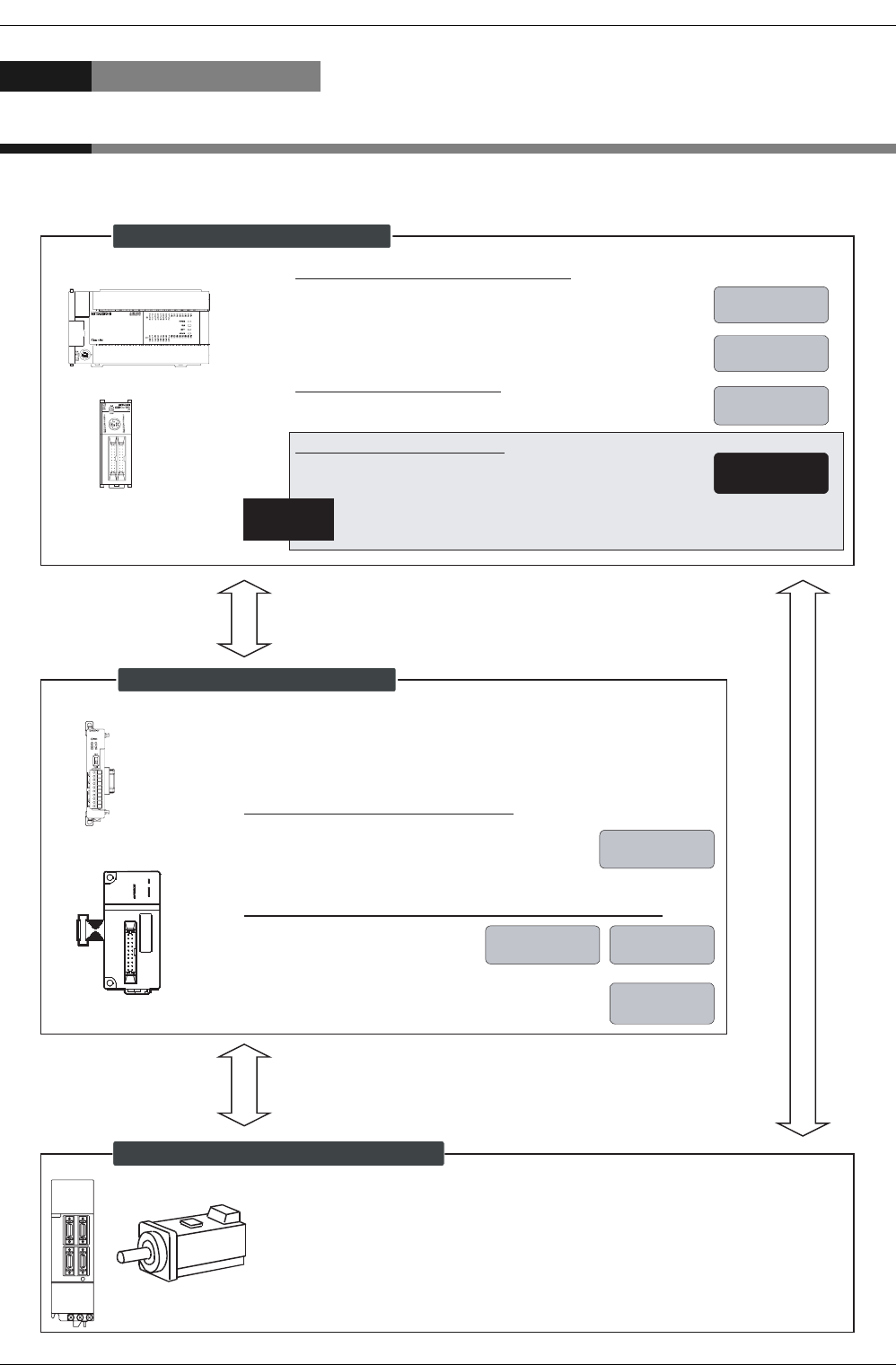
Functions and Use of This Manual
9
Functions and Use of This Manual
The FX3G/FX3U/FX3UC PLC outputs transistor signals from the main unit and also outputs pulses from the
high-speed output adapter and the positioning special function unit/block to the servo motor and stepping
motor to properly control positioning operations.
PLC
FX
3UC
Series
Regarding wiring and installation of PLC:
• Hardware manual
(The hardware manual is enclosed with the product.)
• User's Manual - Hardware Edition
Regarding sequence program:
• Programming manual
Enclosed with
the product
Separate
document
Separate
document
Regarding positioning function:
• User's Manual- Positioning Control Edtion
Separate
document
This document describes the built-in positioning function
setting method, examples of connection, examples of programs, details
for troubleshooting, etc.
This
document
Products needed for positioning
FX
3U
-2HSY-ADP
Special function unit/block
Regarding installation, parts names, operation, and programs:
• USER'S MANUAL
This manual provides the
necessary information.
• HARDWARE/PROGRAMMING MANUAL
This manual provides the necessary information.
Regarding installation and parts names:
• INSTALLATION MANUAL
This manual provides the necessary information.
A separate document is needed for programming
details.
Enclosed with
the product
Either "INSTALLATION MANUAL" or "USER'S MANUAL" is
enclosed with each product.
For the details, refer to User's Manual [Positioning Control]
(this document) or the product manual.
Supplied with
the product Separate
document
Separate
document
POWE
R
ERRO
R
F
P
PG
O
R
P
f
B
fA
STAR
T
CL
R
DO
G
X
1
X
0
FX
2N
-10PG
Servo motor (stepping motor)
Obtain the instruction manual of the servo motor to be connected to your system.
This manual will be needed to set the parameters for the servo amplifier (drive
unit) or wire the servo amplifier.
FX3G/FX3U Series
FX
3G
/FX
3U
/FX
3UC
Series PLC

FX
3G
/FX
3U
/FX
3UC
PLC User's Manual - Positioning Control Edition
Related Manuals
10
Related Manuals
Refer to this document to perform positioning operations with the FX3G/FX3U/FX3UC Series PLC.
For hardware information on the PLC and for details on the special function units/blocks, refer to the
respective manuals.
Indispensable manual
3Manual that may be indispensable
depending on the purpose of use
Abbreriated document
Title of manual Document
number Description Model code
Manuals for PLC
FX3G Series PLC
Enclosed
with the
product
FX3G Series
HARDWARE MANUAL
JY997D33401
The input/output specifications and the
wiring and installation methods for the
FX3G PLC are excerpted from the
FX
3G
Series User’s Manual - Hardware Edition.
For details, refer to the FX3G Series
User’s Manual - Hardware Edition.
-
Separate
document
FX3G Series
User’s Manual -
Hardware Edition
JY997D31301
Provides detailed information on the
hardware, such as the input/output
specifications and the detailed wiring,
installation, and maintenance methods
for the FX3G PLC.
09R521
FX3U Series PLC
Enclosed
with the
product
FX3U Series
HARDWARE MANUAL
JY997D18801
The input/output specifications and the
wiring and installation methods for the
FX3U PLC are excerpted from the
FX
3U
Series User’s Manual - Hardware Edition.
For details, refer to the FX3U Series
User’s Manual - Hardware Edition.
-
Separate
document
FX3U Series
User’s Manual -
Hardware Edition
JY997D16501
Provides detailed information on the
hardware, such as the input/output
specifications and the detailed wiring,
installation, and maintenance methods
for the FX3U PLC.
09R516
FX3UC Series PLC
Enclosed
with the
product
FX3UC(D,DSS) Series
HARDWARE MANUAL
JY997D28601
The input/output specifications and the
wiring and installation methods for the
FX3UC(D,DSS) PLC are excerpted from
the FX3UC Series User's Manual -
Hardware Edition.
For details, refer to the FX3UC Series
User's Manual - Hardware Edition.
-
Enclosed
with the
product
FX3UC-32MT-LT-2
HARDWARE MANUAL
JY997D31601
The input/output specifications and the
wiring and installation methods for the
FX3UC-32MT-LT-2 PLC are excerpted
from the FX3UC Series User's Manual -
Hardware Edition.
For details, refer to the FX3UC Series
User's Manual - Hardware Edition.
-
Separate
document
FX3UC Series
User’s Manual -
Hardware Edition
JY997D28701
Provides detailed information on the
hardware, such as the input/output
specifications and the detailed wiring,
installation, and maintenance methods
for the FX3UC PLC.
09R519

FX
3G
/FX
3U
/FX
3UC
PLC User's Manual - Positioning Control Edition
Related Manuals
11
Programming
Separate
document
FX3G/FX3U/FX3UC
Series Programming
Manual - Basic &
Application Instruction
Edition
JY997D16601
Describes the basic instructions, applied
instructions, and various devices of the
FX3G/FX3U/FX3UC PLC to provide
detailed information on sequence
programming.
09R517
Manuals for positioning control
Common
3Separate
document
FX3G/FX3U/FX3UC
Series User’s Manual -
Positioning Control
Edition (this document)
JY997D16801
Provides detailed information on the
positioning functions incorporated in the
FX3G/FX3U/FX3UC Series.
09R620
Pulse output, positioning
To use each product, also refer to the user's manual (for hardware) of the PLC to be connected to your system.
Enclosed
with the
product
FX3U-2HSY-ADP
Installation Manual JY997D16401
Describes how to handle the high-speed
output special adapter.
To use this adapter, also refer to the
User's Manual for FX3G/FX3U/FX3UC
Series (for positioning control).
-
3
Enclosed
with the
product
FX2N/FX-1PG
User's Manual JY992D65301 Describes how to handle the 1-axis pulse
output special function block. 09R610
Enclosed
with the
product
FX2N-10PG
Installation Manual JY992D91901
Describes how to handle the 1-axis pulse
output special function block.
To use this block, also refer to FX2N-
10PG USER’S MANUAL.
-
3Separate
document
FX2N-10PG
User's Manual JY992D93401 Provides detailed information on the 1-
axis pulse output special function block. 09R611
Enclosed
with the
product
FX2N-10GM
User's Guide JY992D77701
Describes how to handle the 1-axis
positioning special function unit.
To use this unit, also refer to FX2N-
10GM/FX2N-20GM HARDWARE/
PROGRAMMING MANUAL.
-
Enclosed
with the
product
FX2N-20GM
User's Guide JY992D77601
Describes how to handle the 2-axis
positioning special function unit.
To use this unit, also refer to FX2N-
10GM/FX2N-20GM HARDWARE/
PROGRAMMING MANUAL.
-
3Separate
document
FX
2N
-10GM/FX
2N
-20GM
HARDWARE/
PROGRAMMING
MANUAL
JY992D77801
Provides detailed information on the 1-
axis/2-axis positioning special function
unit.
09R612
3
Enclosed
with the
product
FX-PCS-VPS/WIN
SOFTWARE MANUAL JY992D86801 Describes operation details of FX-PCS-
VPS/WIN Setting/Monitoring Tool. 09R609
Enclosed
with the
product
FX3U-20SSC-H
Installation Manual JY997D21101
Describes FX3U-20SSC-H positioning
block specification for I/O, power supply
extracted from the FX3U-20SSC-H User’s
Manual.
For details, refer to FX3U-20SSC-H
User's Manual.
-
3Separate
document
FX3U-20SSC-H
User's Manual JY997D21301 Describes FX3U-20SSC-H Positioning
block details. 09R622
3Separate
document
FX Configurator-FP
Operation Manual JY997D21801 Describes operation details of FX
Configurator-FP Setting/Monitoring Tool. 09R916
Indispensable manual
3Manual that may be indispensable
depending on the purpose of use
Abbreriated document
Title of manual Document
number Description Model code

FX
3G
/FX
3U
/FX
3UC
PLC User's Manual - Positioning Control Edition
Generic Names and Abbreviations Used in Manuals
12
Generic Names and Abbreviations Used in Manuals
Generic name or
abbreviation Description
PLC
FX3G series Generic name for FX3G Series PLC
FX3G PLC or main unit Generic name for FX3G Series PLC main unit
FX3U series Generic name for FX3U Series PLC
FX3U PLC or main unit Generic name for FX3U Series PLC main unit
FX3UC series Generic name for FX3UC Series PLC
FX3UC PLC or main unit Generic name for FX3UC Series PLC main unit
FX2N Series Generic name for FX2N Series PLC
FX2NC Series Generic name for FX2NC Series PLC
Expansion board
Expansion board
Generic name for expansion board
The number of connectable units, however, depends on the type of main unit.
To check the number of connectable units, refer to the User's Manual - Hardware
Editon of the main unit to be used for your system.
Special adapter
Special adapter
Generic name for high-speed input/output special adapter, communication special
adapter, and analog special adapter
The number of connectable units, however, depends on the type of main unit.
To check the number of connectable units, refer to the User's Manual - Hardware
Editon of the main unit to be used for your system.
High-speed input/output
special adapter Generic name for high-speed input/output special adapter
High-speed output special
adapter Generic name for high-speed output special adapter
2HSY-ADP FX3U-2HSY-ADP
High-speed input special
adapter Generic name for high-speed input special adapter
Communication special
adapter Generic name for communication special adapter
Analog special adapter Generic name for analog special adapter
Extension unit
Extension unit
Generic name for input/output extension unit and special extension unit
The number of connectable units, however, depends on the type of main unit.
To check the number of connectable units, refer to the User's Manual - Hardware
Editon of the main unit to be used for your system.
Input/output extension unit
Generic name for input extension unit and output extension unit
The number of connectable units, however, depends on the type of main unit.
To check the number of connectable units, refer to the User's Manual - Hardware
Editon of the main unit to be used for your system.
Input extension unit
Generic name for FX2N Series input/output powered extension unit, input extension
block, FX2NC Series input extension block, and FX0N Series input extension block
The number of connectable units, however, depends on the type of main unit.
To check the number of connectable units, refer to the User's Manual - Hardware
Editon of the main unit to be used for your system.
Output extension unit
Generic name for FX2N Series input/output powered extension unit, output extension
block, FX2NC Series output extension block, and FX0N Series output extension block
The number of connectable units, however, depends on the type of main unit.
To check the number of connectable units, refer to the User's Manual - Hardware
Editon of the main unit to be used for your system.

FX
3G
/FX
3U
/FX
3UC
PLC User's Manual - Positioning Control Edition
Generic Names and Abbreviations Used in Manuals
13
Extension unit
Special function unit/block or
Special extension unit
Generic name for special function unit and special function block
The number of connectable units, however, depends on the type of main unit.
To check the number of connectable units, refer to the User's Manual - Hardware
Edition of the main unit to be used for your system.
Special function unit Generic name for special function unit
Special function block
Generic name for special function block
The number of connectable units, however, depends on the type of main unit.
To check the number of connectable units, refer to the User's Manual - Hardware
Edition of the main unit to be used for your system.
Positioning special
function unit
Generic name for the following models:
FX2N-10GM, FX2N-20GM
Positioning special
function block
Generic name for the following models:
FX3U-20SSC-H
Pulse output special
function block
Generic name for the following models:
FX2N-1PG-E, FX2N-1PG, FX2N-10PG
FX2N-1PG(-E) Generic name for the following models:
FX2N-1PG-E, FX2N-1PG
Optional unit
Extension power supply unit FX3UC-1PS-5V(for FX3UC series), FX3U-1PSU-5V(for FX3G/FX3U series)
Memory cassette FX3G-EEPROM-32L, FX3U-FLROM-16, FX3U-FLROM-64, FX3U-FLROM-64L
Battery FX3U-32BL
FX Series terminal block FX-16E-TB, FX-32E-TB, FX-16EX-A1-TB, FX16EYR-TB, FX-16EYS-TB,
FX-16EYT-TB
Input/output cable
FX-16E-500CAB-S, FX-16E-CAB, FX-32E-CAB, FX-16E-CAB-R,
FX-A32E-CAB
represents 150, 300, or 500.
Input/output connector FX2C-I/O-CON, FX2C-I/O-CON-S, FX2C-I/O-CON-SA
Power cable
FX
2NC
-100MPCB, FX
2NC
-100BPCB, FX
2NC
-10BPCB1
Peripheral unit
Peripheral unit Generic name for programming software, handy programming panel, and HMI
Programming tool
Programming tool Generic name for programming software and handy programming panel
Programming software Generic name for programming software
GX Developer Generic name for SWD5C-GPPW-J/SWD5C-GPPW-E programming software
package
FX-PCS/WIN(-E) Generic name for FX-PCS/WIN or FX-PCS/WIN-E programming software package
Handy programming panel
(HPP) Generic name for FX-30P
,
FX-20P(-E) and FX-10P(-E)
Setting/Monitoring Tool
Setting/monitoring tool Generic name for setting/monitoring tool
FX Configurator-FP Generic name for SWD5C-FXSSC-J/SWD5C-FXSSC-E Setting/monitoring tool
FX-PCS-VPS/WIN(-E) Generic name for FX-PCS-VPS/WIN or FX-PCS-VPS/WIN-E Positioning module
software package for the FX2N-10GM and FX2N-20GM
HMI
GOT1000 series Generic name for GT15, GT11 and GT10
GOT-900 series Generic name for GOT-A900 series and GOT-F900 series
GOT-A900 series Generic name for GOT-A900 series
GOT-F900 series Generic name for GOT-F900 series
ET-940 series Generic name for ET-940 series
Only manuals in Japanese are available for these products
Generic name or
abbreviation Description

FX
3G
/FX
3U
/FX
3UC
PLC User's Manual - Positioning Control Edition
Generic Names and Abbreviations Used in Manuals
14
Drive unit for servo motor and stepping motor
Servo motor Generic name for servo motor or stepping motor
Including pulse input type servo amplifier and drive unit.
Servo amplifier (drive unit) Generic name for pulse input type servo amplifier (drive unit)
MELSERVO series Generic name for MELSERVO-J3, -J2-Super, -J2, -H, and -C series
Other unit
Manual pulse generator Generic name for manual pulse generator (prepared by user)
Manual
FX3G Hardware Edition FX3G Series User's Manual - Hardware Edition
FX3U Hardware Edition FX3U Series User's Manual - Hardware Edition
FX3UC Hardware Edition FX3UC Series User's Manual - Hardware Edition
Programming manual FX3G/FX3U/FX3UC Series Programming Manual - Basic and Applied Instructions
Edition
Communication Control
Edition FX Series User's Manual - Data Communication Edition
Analog Control Edition FX3G/FX3U/FX3UC Series User's Manual - Analog Control Edition
Positioning Control Edition FX3G/FX3U/FX3UC Series User's Manual - Positioning Control Edition
Generic name or
abbreviation Description

A
Common Items
B
Built-in
Positioning
Functions
Apx.
Example
Connection
FX
3G
/FX
3U
/FX
3UC
PLC User's Manual - Positioning Control Edition
Common Items
A - 1
FX3G/FX3U/FX3UC Series Programmable
Controllers
User’s Manual [Positioning Control Edition]
A. Common Items
Foreword
"Common Items" describes an outline of the "positioning" functions incorporated in the MELSEC-F FX3G/
FX3U/FX3UC Series PLC and should be read and understood before attempting to install or use the unit.
Store this manual in a safe place so that you can take it out and read it whenever necessary. Always forward
it to the end user.
© 2005 MITSUBISHI ELECTRIC CORPORATION
This manual confers no industrial property rights or any rights of any other kind, nor does it confer any patent
licenses. Mitsubishi Electric Corporation cannot be held responsible for any problems involving industrial property
rights which may occur as a result of using the contents noted in this manual.

A - 2
FX
3G
/FX
3U
/FX
3UC
PLC User's Manual - Positioning Control Edition
Common Items
Description of Manual (Common Items)
In this manual, the following formats are used for describing the common items:
The above is different from the actual page, as it is provided for explanation only.
Shows the title of the chapter
and the title of the section.
This area shows the title of the
chapter and the title of the
section for the current page.
Indexes the title of
division.
The right side of each
page indexes the title
of the division for the
current page.
Shows the reference.
This area shows the
reference document
(the reference document is
shown next to " ").
If the reference is in
"A. Common items"
division, only the chapter,
section, or subsection
number only will be shown
next to " ".
If the reference is in
another division, the chapter,
section, or subsection
number will be shown
next to " " together with
the title of the division.
Shows the title of the manual and the title
of the division.
This area shows the title of the manual and the title
of the division for the current page.
1st line: Shows the title of the manual.
2nd line: Shows the title of the division.
1 Introduction
1.1 Outline
A - 3
FX
3G
/FX
3U
/FX
3UC
PLC User's Manual - Positioning Control Edition
Common Items
A
Common Items
B
Built-in
Positioning
Functions
Apx.
Example
Connection
1. Introduction
This manual describes the positioning control for the FX3G/FX3U/FX3UC PLC.
In this chapter, a brief description of the positioning products is provided.
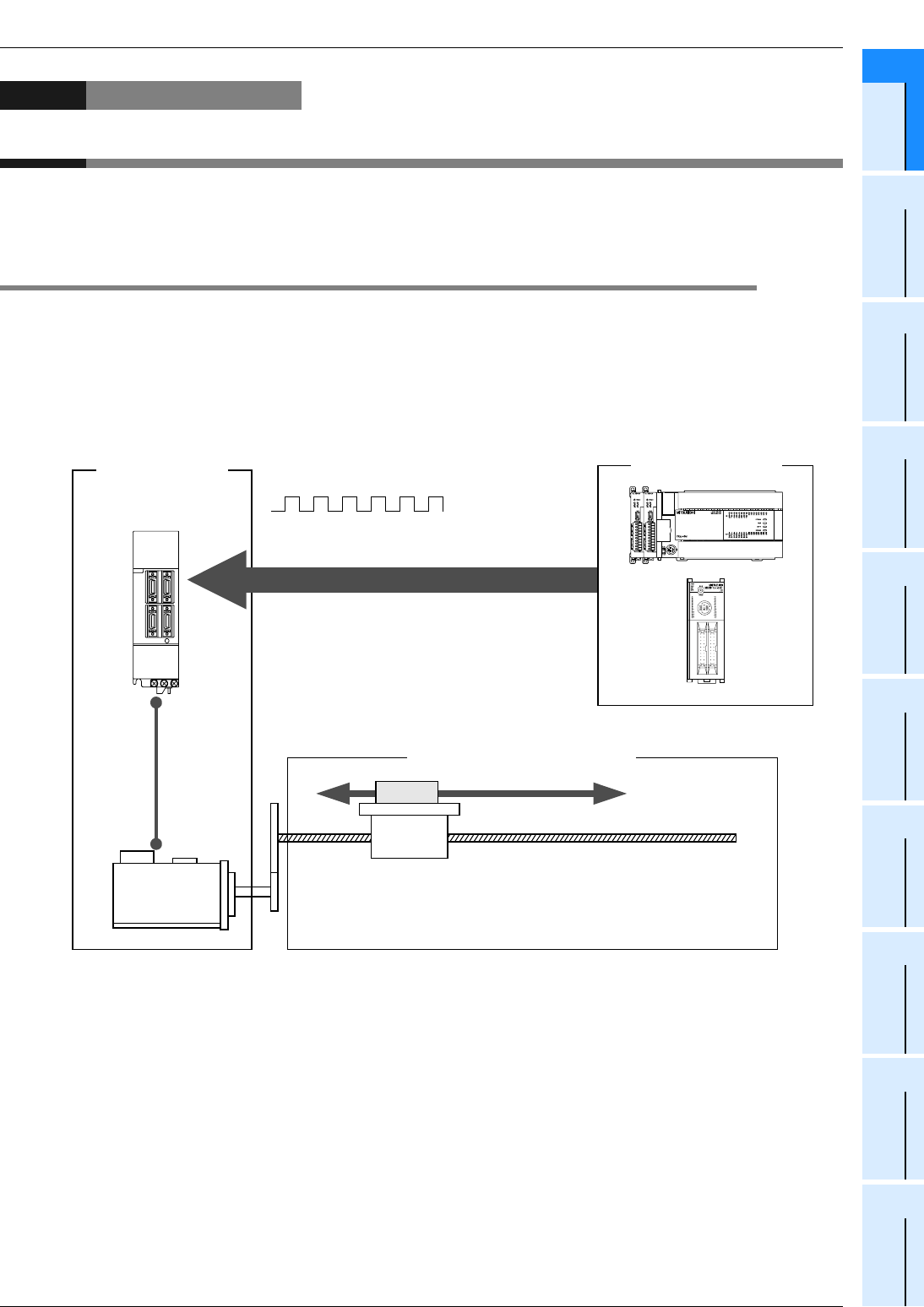
1.1 Outline
The FX3G/FX3U/FX3UC PLC outputs the pulse signal to the servo motor and the stepping motor to control the
positioning operation.
Increase the pulse frequency to increase the motor speed. Increase the number of pulses to increase the
number of motor revolutions. In other words, set the pulse frequency to determine the workpiece transfer
(positioning) speed.
Set the number of pulses to determine the workpiece transfer distance.
Pulse train signal
Pulse frequency
Number of
pulses
: Transfer speed
: Transfer distance
Positioning command
/FX3U/FX3UC PLC
Servo motor or
stepping motor
Workpiece (item to be positioned)
FX3G

1 Introduction
1.2 Introduction of Products Needed for Positioning
A - 4
FX
3G
/FX
3U
/FX
3UC
PLC User's Manual - Positioning Control Edition
Common Items
1.2 Introduction of Products Needed for Positioning
To control the positioning operation, use the positioning functions incorporated in the main unit (including the
special adapters), and the special functions units/blocks. The functions, however, depend on the product(s)
being used. Select the optimum product(s) for the purpose of use.
1.2.1 List of Models
The products needed for positioning are shown in the following table:
1. Main unit (transistor output) and special adapter
*1. Do not exceed the maximum rotation speed of the servo motor or the stepping motor.
*2. Can only be connected to the FX3U PLC.
*3. "2-axes (independent)" in 14-point and 24-point type main units.
*4. Connection of 1 adapter can control 2 axes. Connection of 2 adapters can control up to 4 axes.
*5. The minimum frequency set by the PLSY instruction or PLSV instruction is "1 Hz".
→ For details on the PLSY instruction, refer to the programming manual.
Model Number of
axes
Frequency
(Hz)*1 Unit Output
system Output method Reference
Main unit (transistor output)
FX3U/FX3UC
PLC
3-axes
(independent) 10*5 to 100,000 pulse
Open
collector
system
"Pulse train + direction"
method
B. Built-in
Positioning
Function
FX3G PLC 3-axes*3
(independent) 10*5 to 100,000 pulse
Open
collector
system
"Pulse train + direction"
method
B. Built-in
Positioning
Function
Special adapter
FX3U-2HSY
-ADP*2
2-axes*4
(independent) 10*5 to 200,000 pulse
Differential
line driver
system
"Pulse train + direction"
method or "forward/
reverse rotation pulse
train" method
B. Built-in
Positioning
Function

1 Introduction
1.2 Introduction of Products Needed for Positioning
A - 5
FX
3G
/FX
3U
/FX
3UC
PLC User's Manual - Positioning Control Edition
Common Items
A
Common Items
B
Built-in
Positioning
Functions
Apx.
Example
Connection
2. Special function block/unit*2
*1. Do not exceed the maximum rotation speed of the servo motor or the stepping motor.
*2. Only FX3U and FX3UC PLC can be connected to the above models.
Refer to the manual of each product.
Model Number of
axes
Frequency
(Hz)*1 Unit Output
system Output method
Special function block
FX2N-1PG(-E) 1-axis 10 to 100,000
pulse
µm
10-4inch
mdeg
Open
collector
system
"Pulse train + direction" method or
"forward/reverse rotation pulse train"
method
FX2N-10PG 1-axis 1 to 1,000,000
pulse
µm
10-4inch
mdeg
Differential
line driver
system
"Pulse train + direction" method or
"forward/reverse rotation pulse train"
method
FX3U-20SSC-H
2-axes
(independent/
interpolation)
1 to 50,000,000
pulse
µm
10-4inch
mdeg
SSCNET III
Special function unit
FX2N-10GM 1-axis 1 to 200,000
pulse
µm
10-4inch
mdeg
Open
collector
system
"Pulse train + direction" method or
"forward/reverse rotation pulse train"
method
FX2N-20GM
2-axes
(independent/
interpolation)
1 to 200,000
pulse
µm
10-4inch
mdeg
Open
collector
system
"Pulse train + direction" method or
"forward/reverse rotation pulse train"
method
1 Introduction
1.2 Introduction of Products Needed for Positioning
A - 6
FX
3G
/FX
3U
/FX
3UC
PLC User's Manual - Positioning Control Edition
Common Items
1.2.2 Main Unit (Transistor Output)
The FX3G/FX3U/FX3UC PLC incorporates positioning functionality.
The PLC can output an open collector type pulse train of up to 100 kHz from the general-purpose outputs
(Y000 to Y002), and it can simultaneously control 3 axes*1.
*1. 14-point and 24-point type FX3G PLC can only control 2 axes.
1.2.3 Special Adapter
The special adapter can output differential line driver type pulse trains of up to 200 kHz using the positioning
functionality incorporated in the FX3U PLC, and can simultaneously control up to 4 axes.
Up to 2 high-speed output special adapters (FX3U-2HSY-ADP) can be connected to the FX3U PLC.
• The first FX3U-2HSY-ADP uses Y000 and Y004, and Y001 and Y005.
• The second FX3U-2HSY-ADP uses Y002 and Y006, and Y003 and Y007.
Y000
+
Direction
signal
Y001
+
Direction
signal
Y002
+
Direction
signal
/FX3U/FX3UC PLC
(Transistor output)
1-axis 2-axes 3-axes
Servo motor
(Servo amplifier) Servo motor
(Servo amplifier) Servo motor
(Servo amplifier)
FX3G
FX
3U
PLC
FX
3U
-2HSY-ADP
Y000
+
Y004
Y001
+
Y005
Y002
+
Y006
1st
2-axes 3-axes
2nd
1-axis
Y003
+
Y007
4-axes
Servo motor
(Servo amplifier) Servo motor
(Servo amplifier) Servo motor
(Servo amplifier) Servo motor
(Servo amplifier)
1 Introduction
1.2 Introduction of Products Needed for Positioning
A - 7
FX
3G
/FX
3U
/FX
3UC
PLC User's Manual - Positioning Control Edition
Common Items
A
Common Items
B
Built-in
Positioning
Functions
Apx.
Example
Connection
Cautions when connecting special adapters
• To use high-speed input/output special adapters only (not to use the other special adapters), it is not
necessary to connect the expansion board.
• To use the analog and communication special adapters, be sure to connect the expansion board.
• To use high-speed input/output special adapters together with the analog and/or communication special
adapters, connect the high-speed output special adapters to the expansion board (already connected to
the FX3U PLC) first, and then connect the analog special adapters and/or the communication special
adapter(s).
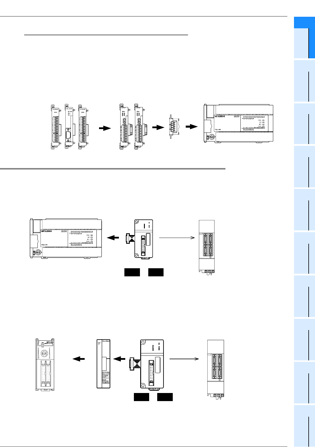
1.2.4 Special Function Unit/Block
Connect a special function unit/block to the FX3U/FX3UC PLC to control positioning operations. Note that a
special function unit can individually control positioning operations.
1. System configuration for FX3U PLC
Up to 8 special function units/blocks can be connected to the FX3U PLC.
→ For details on system configuration, refer to the FX3U Hardware Edition.
2. System configuration for FX3UC PLC
Up to 8*1 special function units/blocks can be connected to the FX3UC PLC.
FX2NC-CNV-IF or FX3UC-1PS-5V is needed to connect special function units/blocks.
*1. Up to 7 special function units/blocks can be connected to the FX3UC-32MT-LT(-2) PLC.
*2. The unit/block number begins with "No. 1" when special function unit/blocks are connected to the
FX3UC-32MT-LT(-2) PLC.
→ For details on system configuration, refer to the FX3UC Hardware Edition.
RD
RDA
RDB
SDA
SDB
SG
SD
FX
3U
PLCExpansion board
High-speed output
special adapter
Analog special adapter
Communication special adapter
Special function block
Special function unit
No.0 No.7
to
Up to 8 units
FX
3U
PLC
POWE
R
ERRO
R
F
P
PG
O
R
P
f
B
fA
STAR
T
CL
R
DO
G
X
1
X
0
FX
2N
-10PG
Servo motor
(Servo amplifier)
FX
3UC
PLC FX
3UC
-1PS-5V
or
FX
2NC
-CNV-IF
Special function block
Special function unit
No.0 No.7
to
Up to 8 units
POWER
ERROR
FP
PGO
RP
f
B
fA
START
CLR
DOG
X1
X0
FX
2N
-10PG
Servo motor
(Servo amplifier)
*2
1 Introduction
1.2 Introduction of Products Needed for Positioning
A - 8
FX
3G
/FX
3U
/FX
3UC
PLC User's Manual - Positioning Control Edition
Common Items
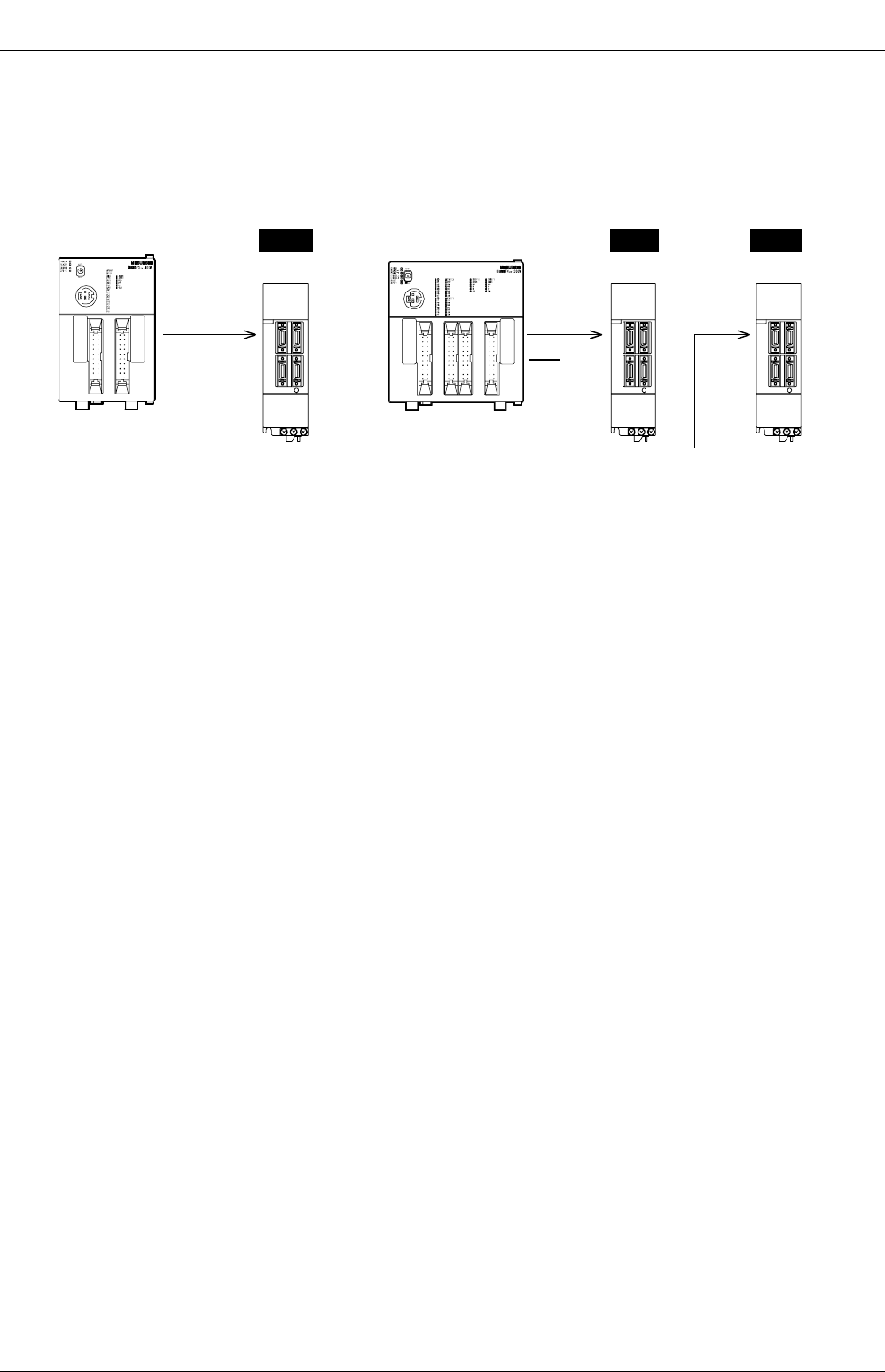
3. Individual operation (FX2N-10GM, FX2N-20GM)
Without connecting special function units (FX2N-10GM, FX2N-20GM) to the PLC, you can operate them
individually.
•FX
2N-10GM can control one 1-axis servo motor or stepping motor.
•FX
2N-20GM can control two 1-axis servo motors or stepping motors.
In addition, up to 48 I/O points can be added.
Servo motor
(Servo amplifier)
2-axes
Servo motor
(Servo amplifier)
1-axis
Servo motor
(Servo amplifier)
1-axis
FX
2N
-10GM FX
2N
-20GM
FX
3G
/FX
3U
/FX
3UC
PLC User's Manual - Positioning Control Edition
Common Items
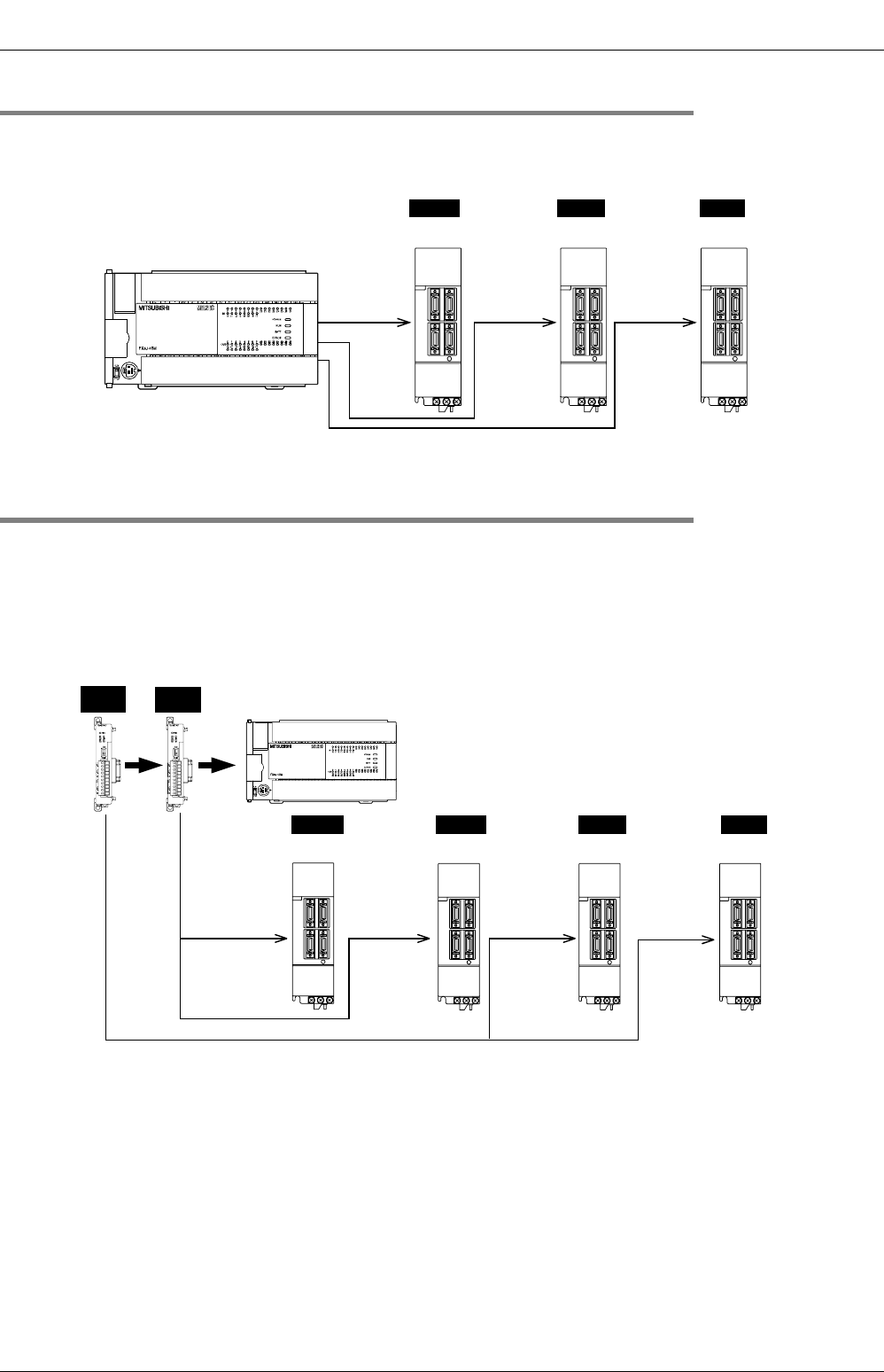
2 Unit Connection
2.1 FX3U PLC
A - 9
A
Common Items
B
Built-in
Positioning
Functions
Apx.
Example
Connection
2. Unit Connection
This chapter displays several block diagrams to illustrate the various combinations of units needed for
positioning control.
2.1 FX3U PLC
*1. The relay output type PLCs do not have pulse output.
*2. The product connects with the servo amplifier via the terminal block, MIL connector (20 pins), or the
SSCNET dedicated connector.
*3. FX3U-20SSC-H only connects with the servo amplifier (MR-J3B) applicable to SSCNET III.
Note:
• For details on the connectable special function units/blocks and system configuration, refer to the following
manual.
→ Refer to the FX3U Hardware Edition.
Up to 2 units can be
connected.
Servo motor or
Stepping motor
*3
European terminal
board
FX
3U
Series
A B
Special function block
Special function unit
- Terminal board (M3)
*2
- MIL connector (20-pin)
*2
- SSCNET dedicated
connector
*2
B and show the unit positions.
(For details of installation, refer to the manuals of special adapter and
special function units/blocks.)
A
FX
3U
-2HSY-ADP
A
B
Up to 8 units can be
connected.
FX
2N
-10PG
fB
fA
START
DOG
X1
X0
POWER
ERROR
FP
PGO
RP
CLR
Terminal block (M3)
(Transistor output)
*1
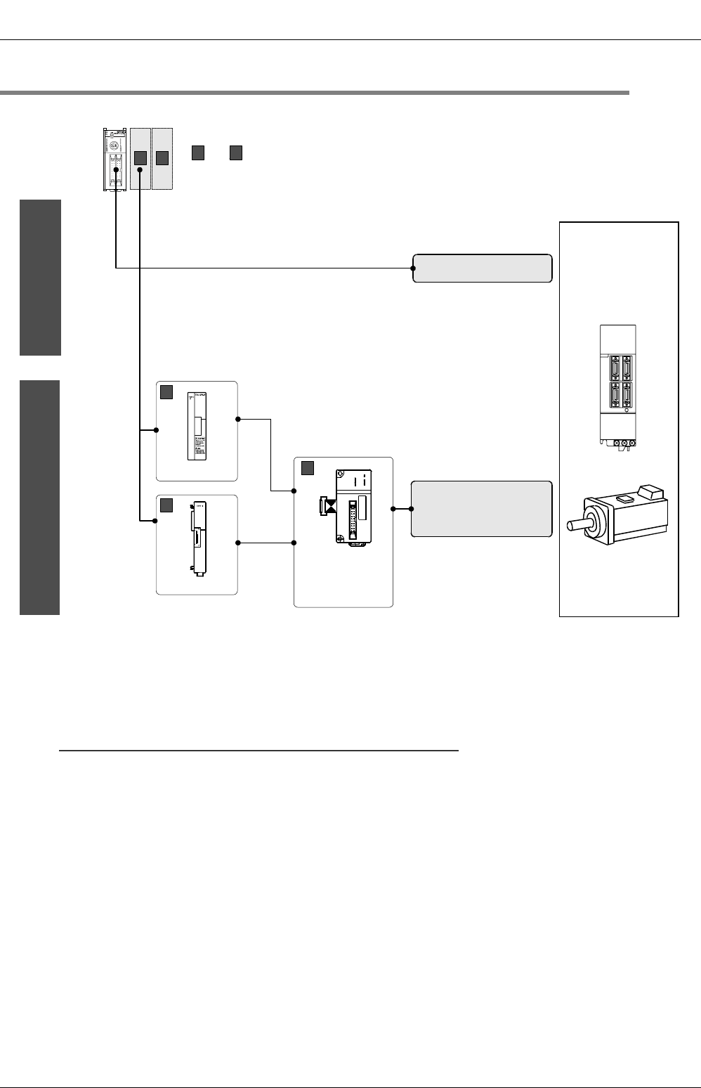
FX
3G
/FX
3U
/FX
3UC
PLC User's Manual - Positioning Control Edition
Common Items
2 Unit Connection
2.2 FX3UC PLC
A - 10
2.2 FX3UC PLC
*1. The product connects with the servo amplifier via the terminal block, MIL connector (20 pins), or the
SSCNET dedicated connector.
*2. FX3U-20SSC-H only connects with the servo amplifier (MR-J3B) applicable to SSCNET III.
*3. Up to 7 special function units/blocks can be connected to the FX3UC-32MT-LT(-2) PLC.
Note:
• Use the FX3UC-1PS-5V (extension power supply unit) only if the 5V DC power supply unit incorporated in
the FX3UC PLC does not have enough capacity.
→ Refer to the FX3UC Hardware Edition.
• For details on the connectable special extension blocks and system configuration, refer to the following
manual.
→ Refer to the FX3UC Hardware Edition.
- Terminal board (M3)
*1
- MIL connector (20-pin)
*1
- SSCNET dedicated
connector
*1
MIL connector (20-pin)
FX
3UC
Series
CB
Up to 8
*3
units can be connected.
C
and show the unit positions.
(For installation details, refer to the manuals of the special adapter and
special function units/blocks.)
B
FX
3UC
-1PS-5V
Servo motor or
Stepping motor
*2
FX
2NC
-CNV-IF
General-purpose output of
main unit
C
C
Special function
block
Special function
unit
B
FX
2N
-10PG
fB
fA
START
DOG
X1
X0
POWER
ERROR
FP
PGO
RP
CLR
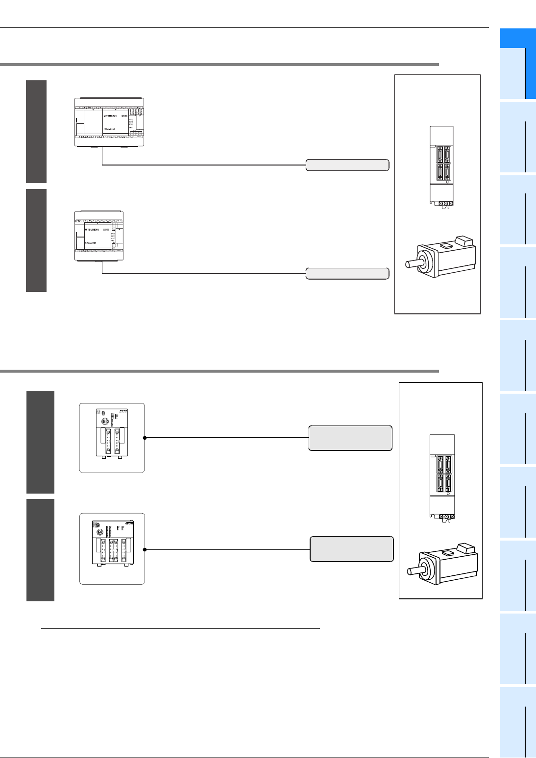
FX
3G
/FX
3U
/FX
3UC
PLC User's Manual - Positioning Control Edition
Common Items
2 Unit Connection
2.3 FX3G PLC
A - 11
A
Common Items
B
Built-in
Positioning
Functions
Apx.
Example
Connection
2.3 FX3G PLC
*1. The relay output type PLCs do not have pulse output.
2.4 Individual Operation of Special Function Unit (FX
2N
-10GM, FX
2N
-20GM)
Note:
• For details on the connection of the FX2N-10GM or FX2N-20GM and for system configuration, refer to the
following manual.
→ Refer to FX2N-10GM, FX2N-20GM HARDWARE/PROGRAMMING MANUAL.
FX
3G
Series (40-point, 60-point type)
Transistor output (Y000 to Y002)*1
Transistor output (Y000, Y001)*1
FX
3G
Series (14-point, 24-point type)
Servo motor or
Stepping motor
Terminal board (M3)
Terminal board (M3)
3 axes can be controlled.
2 axes can be controlled.
Only one axis can be
controlled.
Servo motor or
Stepping motor
MIL connector (20-pin)
MIL connector (20-pin)
FX
2N
-10GM
2 axes can be controlled.
FX
2N
-20GM

3 Comparison of Specifications
3.1 Comparison of Performance Specifications
A - 12
FX
3G
/FX
3U
/FX
3UC
PLC User's Manual - Positioning Control Edition
Common Items
3. Comparison of Specifications
The specifications for each product with positioning functionality are shown below.
3.1 Comparison of Performance Specifications
3.1.1 Built-in Positioning Function [Main Unit (Transistor Output),
High-Speed Output Special Adapter (FX3U-2HSY-ADP)]
*1. 2 independent axes in 14-point and 24-point type FX3G PLC.
*2. Can only be connected to the FX3U PLC. Up to 2 adapters can be connected.
*3. Do not exceed the maximum rotation speed of the servo motor or the stepping motor.
*4. If 2 adapters are connected, Y000 to Y007 will be used. If only one adapter is connected, Y000, Y001,
Y004, and Y005 will be used. The relation between the output of the FX3U-2HSY-ADP and the output
of main unit is described in the following sections.
→ For high-speed output special adapters, refer to Subsection 1.5.3 and Section 4.9 of
"B. Built-in Positioning Function."
Model FX3G/FX3U/FX3UC PLC
(Main unit, transistor output) FX3U-2HSY-ADP*2
Number of control
axes 3 independent axes*1
2 independent axes
(Connect 2 adapters to the main unit to control
4 axes independently.)
Interpolation - -
Pulse output
system Open collector system Differential line driver system
Pulse output
method "Pulse train + direction" method "Pulse train + direction" method
"Forward/reverse rotation pulse train" method
Maximum
frequency*3 100,000Hz 200,000Hz
Acceleration
/deceleration type Automatic trapezoidal acceleration/deceleration
Unit pulse
Positioning range -999,999 to +999,999 (pulse)
Program language Sequence program
Position data 1 point (set in sequence program)
Connection of
manual pulse
generator
--
Detection of
absolute position
(Reads out the cur-
rent value of ABS.)
ABS instruction of the PLC
Others
• Pulses can be output from the general-
purpose outputs (Y000, Y001, and Y002) of
the main unit.
• To be used when a servo amplifier with a
differential line receiver method is
connected.
• To be used when positioning control is
performed with a FX3U Series relay output
type main unit.
• Used in place of the general-purpose
outputs (Y000 to Y007)*4 of the main unit.

3 Comparison of Specifications
3.1 Comparison of Performance Specifications
A - 13
FX
3G
/FX
3U
/FX
3UC
PLC User's Manual - Positioning Control Edition
Common Items
A
Common Items
B
Built-in
Positioning
Functions
Apx.
Example
Connection
3.1.2 Pulse Output Special Function Block [FX2N-1PG(-E), FX2N-10PG]
*1. Do not exceed the maximum rotation speed of the servo motor or the stepping motor.
*2. The position data magnification sets the 1, 10,102 or 103 in parameters.
*3. The positioning range can be set in the range from -2,147,483,648 to +2,147,483,647 pulses.
*4. Up to 200 points (table) can be set for the table operation.
Model FX2N-1PG(-E) FX2N-10PG
Number of control
axes 1 independent axis
Interpolation - -
Pulse output
system Open collector system Differential line driver system
Pulse output
method
"Pulse train + direction" method
"Forward/reverse rotation pulse train" method
Maximum
frequency*1 100,000Hz 1,000,000Hz
Acceleration/decel-
eration type
Automatic trapezoidal
acceleration/deceleration
Automatic trapezoidal
acceleration/deceleration, approximate
S-pattern acceleration/deceleration
Unit pulse, µm, 10-4inch, mdeg
Positioning range
-999,999 to +999,999 [× (Position data magnifi-
cation*2) pulse]
-999,999 to +999,999 [× (Position data magnifi-
cation*2) µm]
-999,999 to +999,999 [× (Position data magnifi-
cation*2) ×10-4 inch]
-999,999 to +999,999 [× (Position data magnifi-
cation*2) mdeg]
-2,147,483,648 to +2,147,483,647 pulse
-2,147,483,648 to +2,147,483,647 [× (Position
data magnification*2) µm]*3
-2,147,483,648 to +2,147,483,647 [× (Position
data magnification*2) ×10-4 inch]*3
-2,147,483,648 to +2,147,483,647 [× (Position
data magnification*2) mdeg]*3
Program language Sequence program (FROM/TO instruction, BFM direct designation)
Position data 1 point (set in sequence program) 1 point (set in sequence program)*4
Connection of
manual pulse
generator
-Connectable
(Differential line driver, open collector)
Detection of
absolute position
(Reads out the cur-
rent value of ABS.)
Using the ABS instruction of the PLC
Others • PLC input/output: 8 points occupied
(Points can be either input or output points.)
• PLC input/output: 8 points occupied
(Points can be either input or output points.)
• From the dedicated start, the high-speed
start by 1 ms at shortest is enabled.
• During positioning operation, the operation
speed can be changed.

3 Comparison of Specifications
3.1 Comparison of Performance Specifications
A - 14
FX
3G
/FX
3U
/FX
3UC
PLC User's Manual - Positioning Control Edition
Common Items
3.1.3 Positioning Special Function Block [FX3U-20SSC-H]
*1. Do not exceed the maximum rotation speed of the servo motor.
*2. The position data magnification sets the 1, 10,102 or 103 in parameters.
*3. The positioning range can be set in the range from -2,147,483,648 to +2,147,483,647 pulses.
*4. The set data (table information) of the table operation can be set up with FX Configurator-FP Setting/
monitor tool.
*5. Up to 300 points (table) can be set for the table operation of the X-/Y-/XY-axis.
Model FX3U-20SSC-H
Number of control
axes 2 independent/simultaneous axes
Interpolation 2-axes linear interpolation, 2-axes circular interpolation
Pulse output
system SSCNET III
Pulse output
method
Maximum
frequency*1 50,000,000Hz
Acceleration/
deceleration type
Automatic trapezoidal acceleration/deceleration,
approximate S-pattern acceleration/deceleration
Unit pulse, µm, 10-4inch, mdeg
Positioning range
-2,147,483,648 to +2,147,483,647 pulse
-2,147,483,648 to +2,147,483,647 [× (Position data magnification*2) µm]*3
-2,147,483,648 to +2,147,483,647 [× (Position data magnification*2) ×10-4 inch]*3
-2,147,483,648 to +2,147,483,647 [× (Position data magnification*2) mdeg]*3
Program language Sequence program (FROM/TO instruction, BFM direct designation)*4
Position data 1 point (set in sequence program)*5
Connection of
manual pulse
generator
Connectable (Differential line driver)
Detection of
absolute position
(Reads out the
current value of
ABS.)
Set in parameters
Others
• PLC input/output: 8 points occupied
(Points can be either input or output points.)
• During positioning operation, the operation speed and/or target address can be changed.

3 Comparison of Specifications
3.1 Comparison of Performance Specifications
A - 15
FX
3G
/FX
3U
/FX
3UC
PLC User's Manual - Positioning Control Edition
Common Items
A
Common Items
B
Built-in
Positioning
Functions
Apx.
Example
Connection
3.1.4 Positioning Special Function Unit [FX2N-10GM, FX2N-20GM]
*1. Do not exceed the maximum rotation speed of the servo motor or the stepping motor.
*2. The minimum command unit sets the 1, 10,102 or 103 in parameters.
*3. The minimum command unit sets the 1, 10-1,10-2 or 10-3 in parameters.
*4. Up to 100 points (table) can be set for the table operation.
Model FX2N-10GM FX2N-20GM
Number of control
axes 1 independent axis 2 independent/simultaneous axes
Interpolation - 2-axes linear interpolation,
2-axes circular interpolation
Pulse output
system Open collector system Open collector system
Pulse output
method
"Pulse train + direction" method
"Forward/reverse rotation pulse train" method
Maximum
frequency*1 200,000Hz 200,000Hz
(100,000Hz during interpolation operation)
Acceleration
/deceleration type Automatic trapezoidal acceleration/deceleration
Unit pulse, mm, 10-1inch, deg
Positioning range
-999,999 to +999,999 [× (minimum command unit*2) pulse]
-999,999 to +999,999 [× (minimum command unit*3) mm]
-999,999 to +999,999 [× (minimum command unit*3) ×10-1 inch]
-999,999 to +999,999 [× (minimum command unit*3) deg]
Program language Cod number system, table system Cod number system
Position data Block designation: 0 to 99 (100 blocks)*4 Block designation (X-axis, Y-axis, 2 axes
simultaneously): 0 to 99 (100 blocks)
Connection of
manual pulse
generator
Connectable (Open collector system)
Detection of
absolute position
(Reads out the cur-
rent value of ABS.)
Set in parameters
Others
• PLC input/output: 8 points occupied
(Points can be either input or output points.)
• This unit can perform positioning operations
independently, without a main unit.
• This unit can perform teaching operation.
• PLC input/output: 8 points occupied
(Points can be either input or output points.)
• This unit can perform positioning operations
independently, without a main unit.
• This unit can perform teaching operation.
• I/O points can be added (48 points,
maximum).
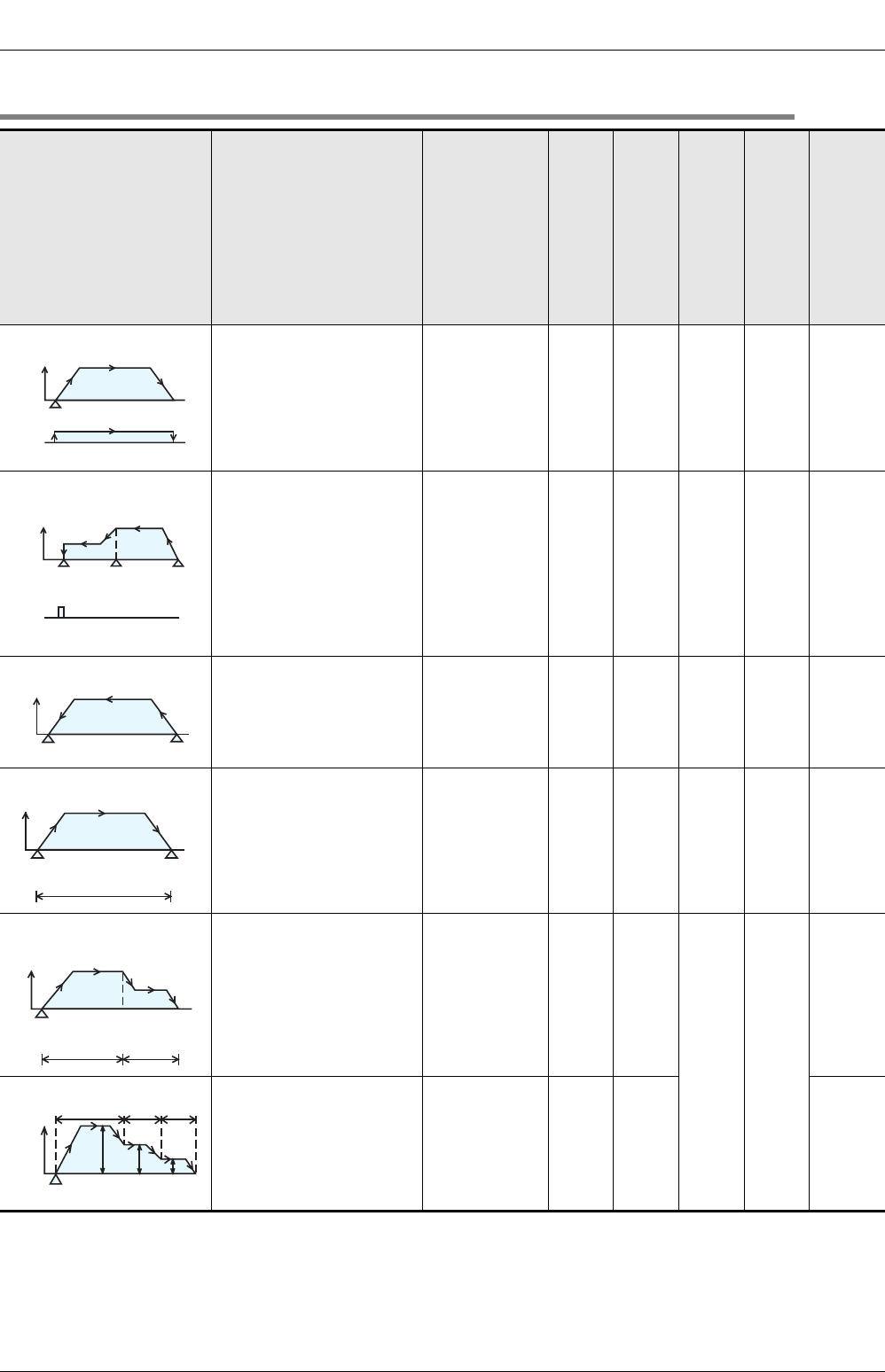
3 Comparison of Specifications
3.2 Comparison of Operation Modes
A - 16
FX
3G
/FX
3U
/FX
3UC
PLC User's Manual - Positioning Control Edition
Common Items
3.2 Comparison of Operation Modes
Positioning operation
pattern Description
Built-in positioning function
FX
3G
/FX
3U
/FX
3UC
PLC
(main unit)
(Transistor output)
FX3U-2HSY-ADP(FX3U)
FX2N-1PG(-E)
FX2N-10PG
FX2N-10GM
FX2N-20GM
FX3U-20SSC-H
Jogging operation
If the forward/reverse rota-
tion command is input, the
motor will rotate in the for-
ward/reverse direction.
3*1 3333 3
Mechanical zero return The mechanical zero return
start command will start the
zero return operation at the
specified speed. At the com-
pletion of the mechanical
zero return, CLEAR signal
will be output.
The DOG search function
applies for each unit.
333333
Electric zero return The SETR instruction will
return the workpiece to the
set electric origin at the maxi-
mum speed set the parame-
ters.
−−−33 −
1-speed positioning
The start command will start
the operation at the speci-
fied operation speed, and the
operation will stop at the tar-
get position.
3*2 3333 3
2-speed positioning
The start command will
transfer the workpiece to the
distance (1) at operation
speed (1), and then to the
distance (2) at operation
speed (2).
−33
3*3 3*4
3
Multi-speed operation
The workpiece will change
speed with the specified
transfer distance.
The figure shows an example
a of 3-speed operation.
−−
3*5 3
*1. Drive to Increment instruction is used.
*2. Drive to Increment/Absolute instructions are used.
*3. The pulse train function of the linear interpolation instruction will perform this operation.
*4. The pulse train function of the linear interpolation instruction will perform this operation.
Operation of only one axis is possible.
*5. The table operation (continuous operation) function will perform this operation.
Speed Jogging speed
Start
JOG
command
Zero return
speed
Creep
speed
Speed
CLEAR
signal
Origin DOG input: ON Start
Speed
Electric origin Start
Maximum speed
Speed
Start
Transfer distance
Operation speed
Target
position
Speed
Start
Operation
speed(1) Operation
speed(2)
Transfer
distance(1) Transfer
distance(2)
Start
Speed P1 P2 P3
V1 V2 V3
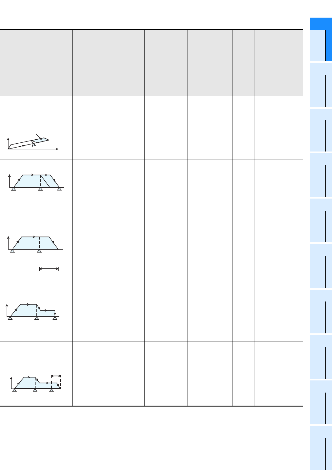
3 Comparison of Specifications
3.2 Comparison of Operation Modes
A - 17
FX
3G
/FX
3U
/FX
3UC
PLC User's Manual - Positioning Control Edition
Common Items
A
Common Items
B
Built-in
Positioning
Functions
Apx.
Example
Connection
Interrupt stop
(linear interpolation [Interrupt
stop])
If an interrupt input turns ON,
during a linear interpolation
operation to the target posi-
tion (x, y) at a vector speed,
the speed will decelerate and
the positioning operation will
stop.
− −−−33
Interrupt stop
If an interrupt input turns ON,
during a positioning opera-
tion, the speed will deceler-
ate and the operation will
stop.
−−33 −3
Interrupt 1-speed positioning
(Interrupt 1-speed constant
quantity feed) If an interrupt input turns ON,
the workpiece will travel to
the specified transfer dis-
tance at the same speed,
where it will decelerate and
the operation will stop.
3*6 3333 3
2-speed positioning with
speed reduction
The operation starts at oper-
ation speed (1) by the start
command. During the opera-
tion, if the speed reduction
command is input, the speed
will decelerate to operation
speed (2). After that, the
operation will be continued at
operation speed (2) until the
stop command is input.
−3−−− −
Interrupt 2-speed positioning
(Interrupt 2-speed constant
quantity feed)
If interrupt input(1) turns ON,
the speed will be reduced to
the 2nd speed. After that, if
interrupt input(2) turns ON,
the operation will decelerate
to stop after moving the
specified transfer distance at
the 2nd speed.
−−333 3
*6. Interrupt positioning instruction performs this operation.
Only available for FX3U and FX3UC PLCs.
Positioning operation
pattern Description
Built-in positioning function
FX
3G
/FX
3U
/FX
3UC
PLC
(main unit)
(Transistor output)
FX3U-2HSY-ADP(FX3U)
FX2N-1PG(-E)
FX2N-10PG
FX2N-10GM
FX2N-20GM
FX3U-20SSC-H
Start point X-axis
Interrupt input
Y-axis Target
position
(x, y)
Ignoring
remaining
distance
Speed
Speed Interrupt
input Target
position
Operation speed
Speed
Start
Operation speed
Interruption command
Transfer distance
Speed
Start Speed reduction
command Stop
command
Operation
speed(1) Operation
speed(2)
Speed
Start
1st speed
Interrupt
input(1) Interrupt
input(2)
2nd speed
Transfer
distance
3 Comparison of Specifications
3.2 Comparison of Operation Modes
A - 18
FX
3G
/FX
3U
/FX
3UC
PLC User's Manual - Positioning Control Edition
Common Items
*7. Variable speed pulse output instruction is used to perform this operation.
Operations with acceleration/deceleration are supported in the FX3U/FX3UC PLC Ver. 2.20 or later and FX3G
PLC.
*8. Operates with acceleration/deceleration.
*9. When interpolation instructions are consecutively set in the program, it will immediately shift to the
next operation. (continuous pass operation).
*10. When the interpolation operation is continuously set in the table operation, it will immediately shift to
the next operation. (Continuation pass function)
Variable-speed operation
The operation will be per-
formed at the operation
speed specified by the PLC.
3*7 33*8 −−
3*8
Linear interpolation
The workpiece will travel to
the target position at the
specified vector speed (inter-
polation operation).
− −−−
3*9 3*10
Circular interpolation
The workpiece will travel to
the specified target position
(x, y) along an arc at the
specified circumferential
speed.
The center coordinate or
radius can be specified.
− −−−
Table operation
A positioning control program
can be set with the table. −−
3
200
points,
maxi-
mum
3
100
points,
maxi-
mum
−
3
X-/Y-/XY-
axis:
300
points,
maxi-
mum
Manual pulse generator
operation
Manual operation can be per-
formed with the manual pulse
generator.
−−
3
30 kHz,
maxi-
mum
3
2 kHz,
maxi-
mum
3
2 kHz,
maxi-
mum
3
100 kHz,
maxi-
mum
Positioning operation
pattern Description
Built-in positioning function
FX
3G
/FX
3U
/FX
3UC
PLC
(main unit)
(Transistor output)
FX3U-2HSY-ADP(FX3U)
FX2N-1PG(-E)
FX2N-10PG
FX2N-10GM
FX2N-20GM
FX3U-20SSC-H
Speed
Start Speed
change Speed
change Stop
X-axis
Y-axis
Start point
Target
position (x, y)
x
y
CW
Start
point
Target position (x, y)
:cw Dotted line
Solid line :ccw
Radius: r
Start point
CCW
Target
position
(x, y)
Radius: -r
No. Position Speed •••
0 200 500
1 500 1000
2 1000 2000
Magnification
Dividing ratio
Input pulse:
30 kHz or less
Phase
A
Phase
B
Servo amplifier
drive unit
Manual pulse
generator

FX
3G
/FX
3U
/FX
3UC
PLC User's Manual - Positioning Control Edition
Built-in Positioning Functions
A
Common Items
B
Built-in
Positioning
Functions
Apx.
Example
Connection
B - 1
FX3G/FX3U/FX3UC Series Programmable
Controllers
User’s Manual [Positioning Control Edition]
B. Built-in Positioning Functions
Foreword
"B. Built-in Positioning Functions" describes the "positioning" functions incorporated in the MELSEC-F FX3G/
FX3U/FX3UC Series PLC and should be read and understood before attempting to install or use the unit.
Also, store this manual in a safe place so that you can take it out and read it whenever necessary. Always
forward it to the end user.
© 2005 MITSUBISHI ELECTRIC CORPORATION
This manual confers no industrial property rights or any rights of any other kind, nor does it confer any patent
licenses. Mitsubishi Electric Corporation cannot be held responsible for any problems involving industrial property
rights which may occur as a result of using the contents noted in this manual.
FX
3G
/FX
3U
/FX
3UC
PLC User's Manual - Positioning Control Edition
Built-in Positioning Functions
B - 2
Description of Manual (Built-in Positioning Function)
In this manual, the following formats are used for describing the built-in positioning functions.
The above is different from the actual page, as it is provided for explanation only
Shows the title of the manual and the title
of the division.
This area shows the title of the manual and the title
of the division for the current page.
1st line: Shows the title of the manual.
2nd line: Shows the title of the division.
Shows the title of the chapter
and the title of the section.
This area shows the title of the
chapter and the title of the
section for the current page.
Indexes the title of
division.
The right side of each
page indexes the title
of the division for the
current page.
Shows the version number
of the compatible PLC.
Compatible
series
Shows the compatible
version numbers.
Ver. 2.20: Version
below 2.20
Ver.2.20 : Version 2.20
or later
Shows the reference.
This area shows the
reference document
(the reference document is
shown next to " ").
If the reference is in the
"A. Common items"
division, only the chapter,
section, or subsection
number will be shown
next to " ".
If the reference is in another
division, the chapter,
section, or subsection
number will be shown
next to " " together with
the title of the division.
1 Outline
1.1 Features
B - 3
FX
3G
/FX
3U
/FX
3UC
PLC User's Manual - Positioning Control Edition
Built-in Positioning Functions
A
Common Items
B
Built-in
Positioning
Functions
Apx.
Example
Connection
1. Outline
This chapter describes a general outline of the positioning modules. Note that the general outputs of the
FX3G/FX3U/FX3UC PLC (transistor output) and FX3U-2HSY-ADP high-speed output special adapter are
needed for positioning control.
1.1 Features
1) The general outputs of the FX3G/FX3U/FX3UC PLC (transistor output) can control up to 3 axes*1 for
positioning operations.
2) If one high-speed output special adapter (FX3U-2HSY-ADP) is connected, the adapter can control up to 2
axes for the positioning operation. If two high-speed output special adapters are connected, the adapters
can control up to 4 axes for the positioning operation.
3) The FX3G/FX3U/FX3UC PLC positioning instructions (applied instructions) are used for positioning control.
4) The general outputs of the FX3G/FX3U/FX3UC PLC (transistor output) can output a pulse train of 100 kHz
(open collector system).
5) The FX3U-2HSY-ADP high-speed output special adapter can output a pulse train of 200 kHz (differential
line driver system).
6) The FX3U-2HSY-ADP high-speed output special adapter can switch the output method between "pulse
train + direction" method and "forward/reverse rotation pulse train" method.
System
...
For a detailed description of
the input/output specifications,
refer to Section 2.4 and
Section 2.5.
...
To check the PLC model,
refer to Section 1.3.
Points and references
...
1-axis 2-axes 3-axes
FX3U/FX3UC PLC
(transistor output)
•If the general outputs of the FX3G/FX3U/FX3UC PLC are used:
3 axes , maximum
...
Number of controllable axes
For examples of connection,
refer to the Appendix.
...
For a detailed description of
the positioning instructions,
refer to Chapters 6 to 11.
•If FX
3U-2HSY-ADP adapters are connected to the FX3U PLC:
...
For a detailed description of the
input/output specifications, refe
r
to Section 2.4 and Section 2.5.
...
To check the PLC model,
refer to Section 1.3.
...
1-axis 2-axes 3-axes
FX3U PLC
4 axes, maximum
For examples of connection,
refer to the Appendix.
...
For a detailed description of the
positioning instructions, refer to
Chapters 6 to 11.
4-axes
FX3U-2HSY
-ADP
...
Number of controllable axes
Servo amplifier (drive unit)etc.
Servo amplifier (drive unit)etc.
2nd 1st
FX3G/
*1
*1. 2 independent axes in 14-point and 24-point type FX3G PLC.
1 Outline
1.2 Setup Procedure for Positioning Control
B - 4
FX
3G
/FX
3U
/FX
3UC
PLC User's Manual - Positioning Control Edition
Built-in Positioning Functions
1.2 Setup Procedure for Positioning Control
DESIGN PRECAUTIONS
• Make sure to have the following safety circuits outside of the PLC to ensure safe system operation even during
external power supply problems or PLC failure.
Otherwise, malfunctions may cause serious accidents.
1) Most importantly, have the following: an emergency stop circuit, a protection circuit, an interlock circuit for
opposite movements (such as normal vs. reverse rotation), and an interlock circuit (to prevent damage to the
equipment at the upper and lower positioning limits).
2) Note that when the PLC CPU detects an error, such as a watchdog timer error, during self-diagnosis, all
outputs are turned off. Also, when an error that cannot be detected by the PLC CPU occurs in an input/output
control block, output control may be disabled.
External circuits and mechanisms should be designed to ensure safe machinery operation in such a case.
3) Note that when an error occurs in a relay, triac or transistor output device, the output could be held either on or
off.
For output signals that may lead to serious accidents, external circuits and mechanisms should be designed to
ensure safe machinery operation in such a case.
DESIGN PRECAUTIONS
• Do not bundle the control line together with or lay it close to the main circuit or power line. As a guideline, lay the
control line at least 100mm (3.94") or more away from the main circuit or power line.
Noise may cause malfunctions.
• Install module so that excessive force will not be applied to the built-in programming port, power connectors, I/O
connectors, communication connectors, or communication cables.
Failure to do so may result in wire damage/breakage or PLC failure.
WIRING PRECAUTIONS
• Make sure to cut off all phases of the power supply externally before attempting installation or wiring work.
Failure to do so may cause electric shock or damage to the product.
• Make sure to attach the terminal cover, offered as an accessory, before turning on the power or initiating operation
after installation or wiring work.
Failure to do so may cause electric shock.
WIRING PRECAUTIONS
• Connect the AC power supply to the dedicated terminals specified in the manual of the PLC main unit.
If an AC power supply is connected to a DC input/output terminal or DC power supply terminal, the PLC will burn
out.
• Connect the DC power supply to the dedicated terminals specified in the manual of the PLC main unit.
If an AC power supply is connected to a DC input/output terminal or DC power supply terminal, the PLC will burn
out.
• Do not wire vacant terminals externally.
Doing so may damage the product.
• Perform class D grounding (grounding resistance: 100Ω or less) to the grounding terminal on the FX3U/FX3G PLC
main unit with a wire 2 mm2 or thicker.
Do not use common grounding with heavy electrical systems (refer to the manual of the PLC main unit).
• Perform class D grounding (grounding resistance: 100Ω or less) to the grounding terminal on the main unit.
Do not use common grounding with heavy electrical systems.
• When drilling screw holes or wiring, make sure cutting or wire debris does not enter the ventilation slits.
Failure to do so may cause fire, equipment failures or malfunctions.
• Install module so that excessive force will not be applied to I/O connectors.
Failure to do so may result in wire damage/breakage or PLC failure.
• Connect input/output cables securely to their designated connectors.
Loose connections may cause malfunctions.
1 Outline
1.2 Setup Procedure for Positioning Control
B - 5
FX
3G
/FX
3U
/FX
3UC
PLC User's Manual - Positioning Control Edition
Built-in Positioning Functions
A
Common Items
B
Built-in
Positioning
Functions
Apx.
Example
Connection
• Make sure to properly wire the FX3U/FX3G Series main unit and FX0N/FX2N Series extension equipment in
accordance with the following precautions.
Failure to do so may cause electric shock, a short-circuit, wire breakage, or damage to the product.
- The disposal size of the cable end should follow the dimensions described in this manual.
- Tightening torque should be between 0.5 and 0.8 N•m.
• Make sure to properly wire to the European terminal board in accordance with the following precautions.
Failure to do so may cause electric shock, a short-circuit, wire breakage, or damage to the product.
- The disposal size of the cable end should follow the dimensions described in this manual.
- Tightening torque should be between 0.22 and 0.25 N•m.
- Twist the end of strand wire and make sure that there are no loose wires.
- Do not solder-plate the electric wire ends.
- Do not connect more than the specified number of wires or electric wires of unspecified size.
- Affix the electric wires so that neither the terminal block nor the connected parts are directly stressed.
• Make sure to properly wire to the FX Series terminal blocks in accordance with the following precautions.
Failure to do so may cause electric shock, a short-circuit, wire breakage, or damage to the product.
- The disposal size of the cable end should follow the dimensions described in this manual.
- Tightening torque should be between 0.5 and 0.8 N•m.
STARTUP AND MAINTENANCE
PRECAUTIONS
• Do not touch any terminal while the PLC's power is on.
Doing so may cause electric shock or malfunctions.
• Before cleaning or retightening terminals, cut off all phases of the power supply externally.
Failure to do so may cause electric shock.
• Before modifying or disrupting the program in operation or running the PLC, carefully read through this manual
and the associated manuals and ensure the safety of the operation.
An operation error may damage the machinery or cause accidents.
STARTUP AND MAINTENANCE
PRECAUTIONS
• Do not disassemble or modify the PLC.
Doing so may cause fire, equipment failures, or malfunctions.
For repair, contact your local Mitsubishi Electric distributor.
• Turn off the power to the PLC before connecting or disconnecting any extension cable.
Failure to do so may cause equipment failures or malfunctions.
• Turn off the power to the PLC before attaching or detaching the following devices.
Failure to do so may cause equipment failures or malfunctions.
- Peripheral devices, expansion boards, and special adapters
- Input/output extension units/blocks and FX Series terminal blocks
WIRING PRECAUTIONS

1 Outline
1.2 Setup Procedure for Positioning Control
B - 6
FX
3G
/FX
3U
/FX
3UC
PLC User's Manual - Positioning Control Edition
Built-in Positioning Functions
Setting of PLC and servo amplifier
•
Selection of output method
(high-speed output special adapter)
•
Setting of command pulse input method and
electronic gear (servo amplifier)
Specifications on incorporated
positioning functions
Refer to Chapter 2
System configuration and unit selection
Wiring
Refer to Chapter 2
and Appendix.
Built-in positioning function
Examples of practical programs
Refer to Division A
"Common Items".
Operation test
Refer to Chapter 5
If the motor does not operate or does not
operate properly, refer to Chapter 13
"Troubleshooting."
Refer to Chapter 12.
Outline
Refer to Chapter 1
Setting of PLC side
Setting of servo amplifier parameters
Refer to Chapter 4.
Motor
specifications
•
Performance
specifications
•
Motor capacity
Programming
Refer to Chapters 6 to 11.
Motor specifications
Refer to the manual of each motor.
Related devices
Refer to Chapter 4.
Outline of system
•
Version numbers of compatible PLCs
•
Version numbers of compatible programming
tools
•
Assignment of input/output numbers
Specifications
•
General specifications, power supply
specifications, performance specifications
•
Input/output specifications
System configuration
•
Unit selection
Wiring
•
Wiring of power supply, input, and
output lines
•
Example of connection to servo amplifier
Related devices
•
Maximum speed, zero return speed
•
Acceleration time, deceleration time
Operation test
•
Creation of program for operation test
•
Motion check
(forward rotation, reverse rotation)
Programming
•
Details on the positioning instructions
Examples of programs
(forward rotation, reverse rotation, zero return)
•
Relay ladder program
•
Step ladder program
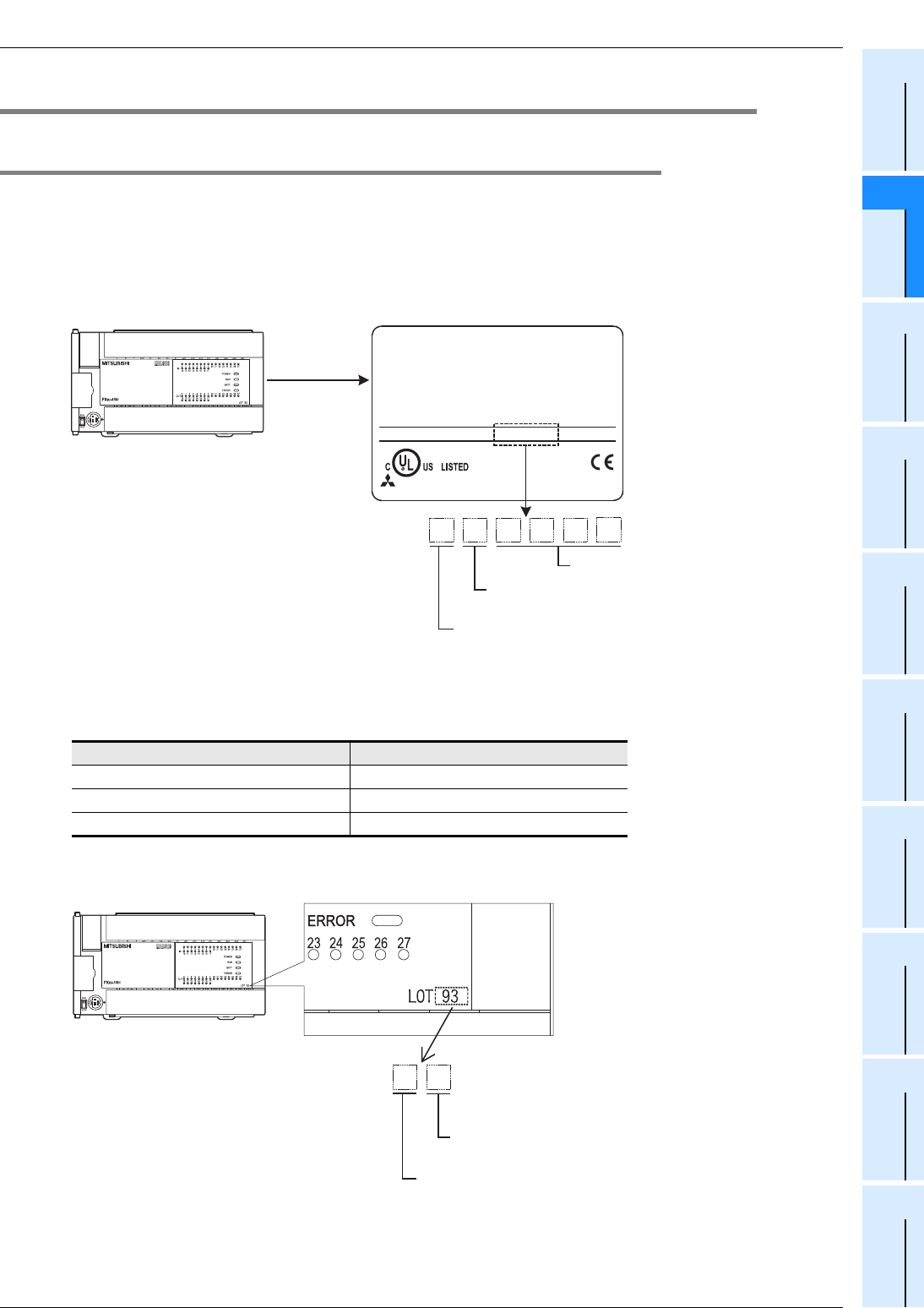
1 Outline
1.3 Version Numbers of Compatible PLCs
B - 7
FX
3G
/FX
3U
/FX
3UC
PLC User's Manual - Positioning Control Edition
Built-in Positioning Functions
A
Common Items
B
Built-in
Positioning
Functions
Apx.
Example
Connection
1.3 Version Numbers of Compatible PLCs
1.3.1 Manufacturer's serial number check method
The year and month of production of the product can be checked on the nameplate, and "LOT" indicated on
the front of the product.
1. Checking the nameplate
The year and month of production of the product can be checked from the manufacturer's serial number
"SERIAL" indicated on the label adhered to the right side of the product.
2. Checking the front of the product
The year and month of production of the product can be checked from the manufacturer's serial number
"LOT" on the front (at the bottom) of the product.
The "LOT" indication is adopted for products manufactured at the following times.
Main unit "LOT" indication adoption time
FX3U Series PLC January 2009 and later
FX3UC Series PLC January 2009 and later
FX3G Series PLC October 2008 and later
Right side
9 3 0 0 0
Control number
Year (Example: 2009): Last digit of year
1
Month (Example: Mar.): (1 to 9 =January to September,
X= October, Y= November, Z= December)
MITSUBISHI
MODEL
100-240VAC 50/60Hz 40W
SERIAL
FX3U-48MR/ES
PROGRAMMABLE
CONTROLLER
930001
OUT:30VDC/240VAC 2A(COSφ=1)
80M1 IND. CONT. EQ.
MITSUBISHI ELECTRIC CORPORATION
MADE IN JAPAN
Example: FX
3U
-48MR/ES (manufacture's serial number: 930001)
Example: FX
3U
-48MR/ES
93
Year (Example: 2009): Last digit of year
Month (Example: Mar.): (1 to 9= January to September,
X= October, Y= November, Z= December)

1 Outline
1.3 Version Numbers of Compatible PLCs
B - 8
FX
3G
/FX
3U
/FX
3UC
PLC User's Manual - Positioning Control Edition
Built-in Positioning Functions
1.3.2 Version check
The D8001 special data register contains information for determining the PLC version.
1.3.3 Version upgrade history
Compatible PLC Compatible version
number
Date (month and year)
of production Remarks
FX3U PLC
Ver. 2.20 (initial product)
or later After May 2005
Equivalent to FX3UC PLC Ver. 2.20
Functions specified as "Ver.2.20 or
later" in this manual are applicable.
Ver. 2.30 or later After November 2005
FX3UC PLC
Ver. 1.00 (initial product)
or later After January 2004
Ver. 1.30 or later After August 2004
• DVIT instruction function is added.
- Designation of interrupt input
signal
Ver. 2.20 or later After May 2005
Functions specified as "Ver.2.20 or
later" in this manual are applicable.
• TBL instruction is added.
- GX Developer can set the
positions using parameters.
• PLSV instruction function is added.
- Acceleration/deceleration function
• DVIT instruction function is added.
- User interruption mode
• DSZR, ZRN instruction functions are
added.
- Designation of destination for
CLEAR signal to be output
Ver. 2.30 or later After November 2005
FX3G PLC Ver. 1.00 (initial product)
or later After June 2008
D8001
PLC type and
version
2 4 1 0 0
Version information (Example: Ver. 1.00)
PLC type Example: 24 = FX3U/FX3UC PLC
26 = FX3G PLC

1 Outline
1.4 Version Numbers of Compatible Programming Tools
B - 9
FX
3G
/FX
3U
/FX
3UC
PLC User's Manual - Positioning Control Edition
Built-in Positioning Functions
A
Common Items
B
Built-in
Positioning
Functions
Apx.
Example
Connection
1.4 Version Numbers of Compatible Programming Tools
The built-in positioning functions depend on the version of the FX3G/FX3U/FX3UC PLC. Select a compatible
version of GX Developer for programming.
→ For details on version numbers of compatible PLCs, refer to Section 1.3.
1) FX3U PLC
*1. For Ver. 8.23Z or 8.24A of GX Developer, the model to be selected is FX3UC.
2) FX3UC PLC
*1. For Ver. 8.23Z or 8.24A of GX Developer, the model to be selected is FX3UC.
3) FX3G PLC
Version
number of FX3U
PLC
Model
(Software model)
Version number of
compatible GX Developer Remarks
Ver.2.20 or later GX Developer
SWD5C-GPPW-J
SWD5C-GPPW-E
Ver. 8.23Z or later • Supports FX3U PLCs (Ver.2.20 or later).
Model selection: FX3U(C)*1
Ver.2.30 or later Ver. 8.29F or later • Supports FX3UC PLCs (Ver.2.30 or later).
Model selection: FX3U(C)
Version number
of FX3UC PLC
Model
(Software model)
Version number of
compatible GX Developer Remarks
Ver.1.00 or later
GX Developer
SWD5C-GPPW-J
SWD5C-GPPW-E
Ver.8.13P or later • Supports FX3UC PLCs (Ver.1.00 or later).
Model selection: FX3UC
Ver.1.30 or later Ver.8.18U or later • Supports FX3UC PLCs (Ver.1.30 or later).
Model selection: FX3UC
Ver.2.20 or later Ver.8.23Z or later • Supports FX3UC PLCs (Ver.2.20 or later).
Model selection: FX3U(C)*1
Ver.2.30 or later Ver. 8.29F or later • Supports FX3UC PLCs (Ver.2.30 or later).
Model selection: FX3U(C)
Version number
of FX3G PLC
Model
(Software model)
Version number of
compatible GX Developer Remarks
Ver.1.00 or later
GX Developer
SWD5C-GPPW-J
SWD5C-GPPW-E
Ver.8.72A or later • Supports FX3G PLCs (Ver.1.00 or later).
Model selection: FX3G

1 Outline
1.5 Assignment of Input/Output Numbers
B - 10
FX
3G
/FX
3U
/FX
3UC
PLC User's Manual - Positioning Control Edition
Built-in Positioning Functions
1.5 Assignment of Input/Output Numbers
1.5.1 Assignment of Input Numbers
Assign the input numbers of the FX3G/FX3U/FX3UC PLC as follows:
Application Input number Remarks
Stop command All input
points
Connect a line to any input.
If the line-connected input is turned on, turn off the positioning instruction signal
must be turned off.
Zero return
command
All input
points
Connect a line to any input.
If the line-connected input is turned on, the DSZR or ZRN instruction must be
turned on.
Near-point
signal
(DOG)
All input
points
Connect a line to the input of the near-point signal (DOG) specified by DSZR or
ZRN instruction.
→ For details on the near-point signal of the DSZR instruction, refer to
Section 6.2.
→ For details on the near-point signal of the ZRN instruction, refer to
Section 6.3.
Point:
• To use the DSZR instruction:
If X000 to X017*1 of the main unit are set for the near-point signal (DOG), the
near-point signal (DOG) will be monitored at 1ms intervals.
• To use the ZRN instruction:
If X000 to X007 of the main unit are set for the near-point signal (DOG), the PLC
interruption function will be used for processing of the near-point signal (DOG).
Zero-phase
signal X000 to X007 Connect a line to the input (X000 - X007) specified for the zero-phase signal (this
input is specified by DSZR instruction).
ABS read All input
points
Connect a line if it is necessary to use the absolute position detection system.
Connect a line to the input specified by the ABS instruction.
Use 3 consecutive input points for this function.
JOG command All input
points
Connect a line to any input.
If the line-connected input is turned on, the DRVI instruction for the jogging motion
must be turned on.
1 Outline
1.5 Assignment of Input/Output Numbers
B - 11
FX
3G
/FX
3U
/FX
3UC
PLC User's Manual - Positioning Control Edition
Built-in Positioning Functions
A
Common Items
B
Built-in
Positioning
Functions
Apx.
Example
Connection
Interrupt input X000 to X007
The interrupt input depends on the pulse output destination specified by the DVIT
instruction*2 as shown in the following table. If the version number of the PLC is
1.30 or higher, the interrupt input can be specified.
FX3UC PLC Ver. 1.30 or later
If the interrupt input specification function is used, the D8336
register (interrupt input specification register) can specify the
interrupt input number (X000 - X007) for each pulse output
destination.
→ For details on the interrupt input specification method, refer to
Subsection 4.3.7.
FX3U/FX3UC PLC*4 Ver. 2.20 or later
If the interrupt input
specification
function is used, the D8336
register (interrupt input
specification
register) can specify the
interrupt input number (X000 - X007) for each pulse output
destination, or the user interrupt input command can be
specified.
→ For details on the user interrupt input command, refer to
Subsection 4.3.7.
The user interrupt input command depends on the pulse output destination as
shown in the following table.
Forward
rotation limit
(LSF)
All input
points
Connect a line to any input.
If the line-connected input is turned on, the forward limit relay must be turned on.
The forward limit relay depends on the pulse output destination as shown in the
following table.
Reverse rota-
tion limit (LSR)
All input
points
Connect a line to any input.
If the line-connected input is turned on, the reverse limit relay must be turned on.
The reverse limit relay depends on the pulse output destination as shown in the
following table:
Application Input number Remarks
Pulse output destination interrupt input
Y000 X000
Y001 X001
Y002 X002
Y003*3 X003
Pulse output destination User interrupt input command
Y000 M8460
Y001 M8461
Y002 M8462
Y003*3 M8463
Pulse output destination Forward limit relay
Y000 M8343
Y001 M8353
Y002*5 M8363
Y003*3 M8373
Pulse output destination Reverse limit relay
Y000 M8344
Y001 M8354
Y002*5 M8364
Y003*3 M8374
1 Outline
1.5 Assignment of Input/Output Numbers
B - 12
FX
3G
/FX
3U
/FX
3UC
PLC User's Manual - Positioning Control Edition
Built-in Positioning Functions
*1. X000 to X007 for FX3U-16M,
FX
3UC
-16M
.
X000 to X007 for FX3G PLC (main unit).
*2. Interrupt outputs are supported only in the FX3U and FX3UC PLC.
*3. Y003 can be specified as the pulse output destination only if 2 high-speed output special adapters are
connected to the FX3U PLC.
*4. Ver.2.20 is assigned to the initial product of the FX3U PLC.
*5. Y002 (pulse output destination) cannot be specified when the 14-point or 24-point type FX3G PLC is
connected.
1.5.2 Assignment of Output Numbers
1. FX3G/FX3U/FX3UC Series main unit (transistor output)
*1. Y002 (pulse output destination) cannot be specified when the 14-point or 24-point type FX3G PLC is
connected.
*2. Specify an output number for transistor output.
Application Output
number Remarks
Pulse train signal
(Pulse output
destination)
Y000
Y001
Y002*1
Connect a line to the output (Y000 - Y002) specified for the pulse output
designation (this output is specified by the positioning instruction).
Direction signal
(Rotational
direction signal)
All output
points*2
Connect a line to any output.
Connect a line to the output specified for the rotation direction signal (this signal is
specified by the positioning instruction).
CLEAR signal All output
points*2
Connect a line if it is necessary to use DSZR/ZRN instruction to output the CLEAR
signal.
The CLEAR signal output depends on the pulse output destination specified by
the DSZR/ZRN instruction. If the PLC version is later than the following number,
the CLEAR signal can be specified.
FX3U/FX3UC PLC (transistor output) Ver. 2.20 or later:
If the CLEAR signal device specification function is used, the
CLEAR signal device specification register can specify an
output for each pulse output destination.
→ For details on the CLEAR signal device specification method, refer to
Subsection 4.3.4.
The CLEAR signal device specification register depends on the pulse output
destination as shown in the following table:
Pulse output destination CLEAR signal
Y000 Y004
Y001 Y005
Y002*1 Y006
Pulse output destination CLEAR signal device specification register
Y000 D8464
Y001 D8465
Y002 D8466

1 Outline
1.5 Assignment of Input/Output Numbers
B - 13
FX
3G
/FX
3U
/FX
3UC
PLC User's Manual - Positioning Control Edition
Built-in Positioning Functions
A
Common Items
B
Built-in
Positioning
Functions
Apx.
Example
Connection
2. High-speed output special adapter
*1. Specify an output number for transistor output.
Application Terminal Output number Remarks
1st 2nd
Pulse train sig-
nal/forward
rotation pulse
train
(pulse output
destination)
Y0/2+
Y0/2- Y000 Y002
Connect a line to determine the pulse train signal or the forward
rotation pulse train for the 1st axis of each high-speed output
special adapter.
For the 1st adapter, specify Y000 as the pulse output destination
of the positioning instruction. For the 2nd adapter, specify Y002
as the pulse output destination of the positioning instruction.
Y1/3+
Y1/3- Y001 Y003
Connect a line to determine the pulse train signal or the forward
rotation pulse train for the 2nd axis of each high-speed output
special adapter.
For the 1st adapter, specify Y001 as the pulse output destination
of the positioning instruction. For the 2nd adapter, specify Y003
as the pulse output destination of the positioning instruction.
Direction sig-
nal/reverse
rotation pulse
train
(rotation
direction
signal)
Y4/6+
Y4/6- Y004 Y006
Connect a line to determine the direction signal or the reverse
rotation pulse train for the 1st axis of each high-speed output
special adapter.
For the 1st adapter, specify Y004 as the rotation direction signal
of the positioning instruction. For the 2nd adapter, specify Y006
as the rotation direction signal output of the positioning
instruction.
Y5/7+
Y5/7- Y005 Y007
Connect a line to determine the direction signal or the reverse
rotation pulse train for the 2nd axis of each high-speed output
special adapter.
For the 1st adapter, specify Y005 as the rotation direction signal
output of the positioning instruction. For the 2nd adapter, specify
Y007 as the rotation direction signal output of the positioning
instruction.
CLEAR signal All output points *1
Connect a line if it is necessary to use the DSZR/ZRN instruction
to output the CLEAR signal.
Using the CLEAR signal device specification function, specify the
output number for the transistor output. In this case, do not
specify an output device if the device is already specified for
outputting the rotational direction signal.
→ For details on the CLEAR signal device specification
method, refer to Subsection 4.3.4.
The CLEAR signal device specification register depends on the
pulse output destination as shown in the following table:
Point:
The CLEAR signal output that is initially set for the DSZR/ZRN
instruction is the same output as the direction signal (rotation
direction signal, reverse pulse train). Be sure to specify an
output number of another transistor output using the CLEAR
signal device specification function.
Pulse output destination CLEAR signal device
specification register
Y000 D8464
Y001 D8465
Y002 D8466
Y003 D8467

1 Outline
1.5 Assignment of Input/Output Numbers
B - 14
FX
3G
/FX
3U
/FX
3UC
PLC User's Manual - Positioning Control Edition
Built-in Positioning Functions
1.5.3 Connection of High-Speed Output Special Adapter
1. When the FX3U-16MR/ES uses an instruction that needs the high-speed inputting operation,
the main unit should have enough input terminals. Before selecting the main unit, be sure
to check the number of input points needed for the operation.
2. Specify the rotational direction signal of the positioning instruction depending on the
setting of each pulse output destination as shown in the following table:
3. To output the CLEAR signal using DSZR/ZRN instruction
The CLEAR signal output that is initially set for the DSZR/ZRN instruction is the same output as the direction
signal/reverse pulse train (rotation direction signal). Be sure to specify an output number of another transistor
output using the CLEAR signal device specification function.
→ For details on the CLEAR signal device specification method, refer to
Subsection 4.3.4.
4. If high-speed output special adapter is connected to the FX3U Series main unit, the output
numbers will be assigned in the same way as the main unit.
If an output number assigned to a high-speed output special adapter is turned on by the sequence program,
the corresponding output of the main unit will also be turned on. Do not connect a line to both output
terminals. Connect a line to one of the output terminals.
The outputs of the high-speed output special adapter and the main unit will be turned on as shown in the
following table:
*1. The output frequency limit of the main unit transistor output is 100 kHz. When operating a load with a
pulse frequency exceeding 100 kHz, PLC failure may occur.
*2. Furthermore, use of the PWM (FNC58) is not recommended with the relay type main unit and the
high-speed adapters due to chattering of the relay contacts.
Pulse output destination Rotation direction signal
1st Y000 Y004
Y001 Y005
2nd Y002 Y006
Y003 Y007
Unit
Output operation
PLSY,PLSR,DSZR,
DVIT,TBL,ZRN,PLSV,D
RVI,DRVA instruction.
PWM instruction Other
instruction
FX3U Series main unit
of relay output type
While instruction is
activated, relevant
output is ON. (LED is
also ON.)
Use of the PWM (FNC58) instruction is not
compatible with a relay type main unit.*2 Operated
FX3U Series main unit
of transistor output
type
Operated*1 Operated Operated
High-speed output
special adapter Operated
Operated
The main unit should use the transistor output
type.*2
Operated
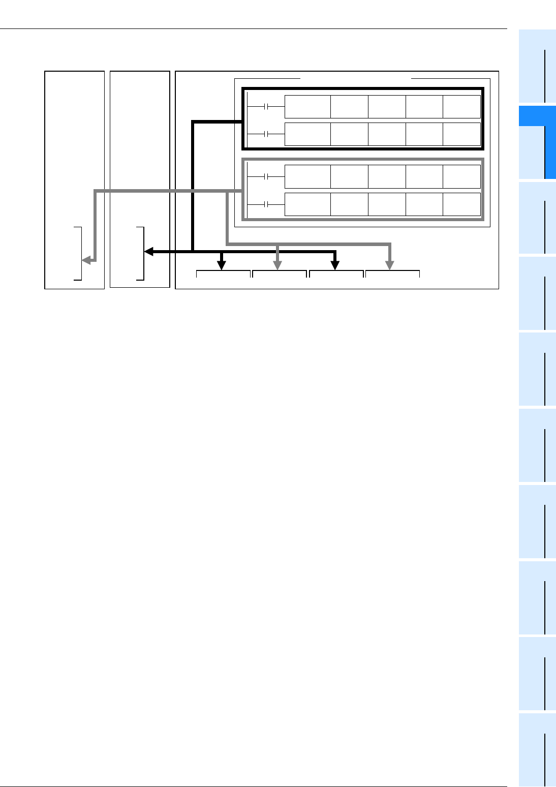
1 Outline
1.5 Assignment of Input/Output Numbers
B - 15
FX
3G
/FX
3U
/FX
3UC
PLC User's Manual - Positioning Control Edition
Built-in Positioning Functions
A
Common Items
B
Built-in
Positioning
Functions
Apx.
Example
Connection
Block diagram
FX
3U
Series main unit
Y000 Y001 Y002 Y003 Y004 Y005 Y006 Y007
FX
3U
-2HSY
-ADP
Y000
Y001
Y004
Y005
FX
3U
-2HSY
-ADP
Y002
Y003
Y006
Y007
Sequence program
FNC 158
DRVA
K15000 K10000 Y001 Y005
FNC 159
DRVA
K10000 K10000 Y002 Y006
FNC 158
DRVI
K30000 K20000 Y000 Y004
FNC 159
DRVI
K1000 K5000 Y003 Y007
1st
2nd
FX
3G
/FX
3U
/FX
3UC
PLC User's Manual - Positioning Control Edition
Built-in Positioning Functions
2 Specifications
B - 16
2. Specifications
DESIGN PRECAUTIONS
• Make sure to have the following safety circuits outside of the PLC to ensure safe system operation even during
external power supply problems or PLC failure.
Otherwise, malfunctions may cause serious accidents.
1) Most importantly, have the following: an emergency stop circuit, a protection circuit, an interlock circuit for
opposite movements (such as normal vs. reverse rotation), and an interlock circuit (to prevent damage to the
equipment at the upper and lower positioning limits).
2) Note that when the PLC CPU detects an error, such as a watchdog timer error, during self-diagnosis, all
outputs are turned off. Also, when an error that cannot be detected by the PLC CPU occurs in an input/output
control block, output control may be disabled.
External circuits and mechanisms should be designed to ensure safe machinery operation in such a case.
3) Note that when an error occurs in a relay, triac or transistor output device, the output could be held either on or
off.
For output signals that may lead to serious accidents, external circuits and mechanisms should be designed to
ensure safe machinery operation in such a case.
DESIGN PRECAUTIONS
• Do not bundle the control line together with or lay it close to the main circuit or power line. As a guideline, lay the
control line at least 100mm (3.94") or more away from the main circuit or power line.
Noise may cause malfunctions.
• Install module so that excessive force will not be applied to the built-in programming port, power connectors, I/O
connectors, communication connectors, or communication cables.
Failure to do so may result in wire damage/breakage or PLC failure.
DISPOSAL PRECAUTIONS
• Please contact a certified electronic waste disposal company for the environmentally safe recycling and disposal
of your device.
TRANSPORTATION
PRECAUTIONS
• Before transporting the PLC, turn on the power to the PLC to check that the BATT LED is off.
If the PLC is transported with the BATT LED on or the battery exhausted, the battery-backed data may be
unstable during transportation.
• The PLC is a precision instrument. During transportation, avoid impacts larger than those specified in the general
specifications of the PLC main unit manual. Failure to do so may cause failures in the PLC. After transportation,
verify the operations of the PLC.

FX
3G
/FX
3U
/FX
3UC
PLC User's Manual - Positioning Control Edition
Built-in Positioning Functions
2 Specifications
2.1 General Specifications
B - 17
A
Common Items
B
Built-in
Positioning
Functions
Apx.
Example
Connection
2.1 General Specifications
For the FX
3G
/FX
3U
/FX
3UC
PLC general specifications, refer to the following manuals. Note that the
high-speed output special adapter general specifications are the same as the PLC excluding the specifications
shown in the following table.
→ For the FX3G PLC general specifications, refer to the FX3G Hardware Edition.
→ For the FX3U PLC general specifications, refer to the FX3U Hardware Edition.
→ For the FX3UC PLC general specifications, refer to the FX3UC Hardware Edition.
2.2 Power Supply Specifications
For the FX3G/FX3U/FX3UC PLC power supply specifications, refer to the following manuals. The power supply
specifications of the high-speed output special adapter are shown in the following table.
→ For the FX3G PLC power supply specification, refer to the FX3G Hardware Edition.
→ For the FX3U PLC power supply specification, refer to the FX3U Hardware Edition.
→ For the FX3UC PLC power supply specifications, refer to the FX3UC Hardware Edition.
Item Specifications
Withstand voltage 500V AC, for 1 minute Between output terminal of high-speed output
special adapter and grounding terminal of PLC.
Insulation resistance 5M Ω or more using 500V DC
insulation tester
Item Specifications
Output circuit drive
power supply
24V DC, 60 mA
The service power of the main unit is supplied internally.
Adapter drive power
supply
5V DC, 30 mA
The adapter driver power is internally supplied from the 5V DC power supply unit of the
main unit.

FX
3G
/FX
3U
/FX
3UC
PLC User's Manual - Positioning Control Edition
Built-in Positioning Functions
2 Specifications
2.3 Performance Specifications
B - 18
2.3 Performance Specifications
*1. For MELSERVO Series amplifiers, use a sink input/sink output type PLC.
*2. Can only be connected to the FX3U PLC. Up to 2 adapters can be connected.
*3. If 2 adapters are connected, Y000 to Y007 will be used. If only one adapter is connected, Y000,
Y001, Y004, and Y005 will be used. The relation between the output of the FX3U-2HSY-ADP and the
output of main unit is described in the following sections.
→ To use high-speed output special adapters, refer to Subsection 1.5.3 and Section 4.9 of "B. Built-in
Positioning Function".
*4. 2 independent axes in 14-point and 24-point type FX3G PLC.
Model FX3G/FX3U/FX3UC PLC*1
(main unit, transistor output) FX3U-2HSY-ADP*2
Number of control axes 3 independent axes*4
2 independent axes
(Connect 2 adapters to the main unit to
control 4 axes independently.)
Interpolation - -
Pulse output system Open collector system Differential line driver system
Pulse output method "Pulse train + direction" method
"Pulse train + direction" method
"Forward/reverse rotation pulse train"
method
Maximum frequency 100,000Hz 200,000Hz
Acceleration/
deceleration type Automatic trapezoidal acceleration/deceleration
Unit pulse
Positioning range -999,999 to +999,999(pulse)
Program language Sequence program
Position data 1 point (set in sequence program)
Connection of manual
pulse generator --
Detection of absolute
position
(Reads out the current
value of ABS.)
ABS instruction
Others
• Pulses can be output from the general-
purpose outputs (Y000, Y001, and
Y002) of the main unit.
• To be used when a servo amplifier with
a differential line receiver method is
connected.
• To be used when positioning control is
performed with a FX3U Series relay
output type main unit.
• Used in place of the general-purpose
outputs (Y000 to Y007)*3 of the main
unit.
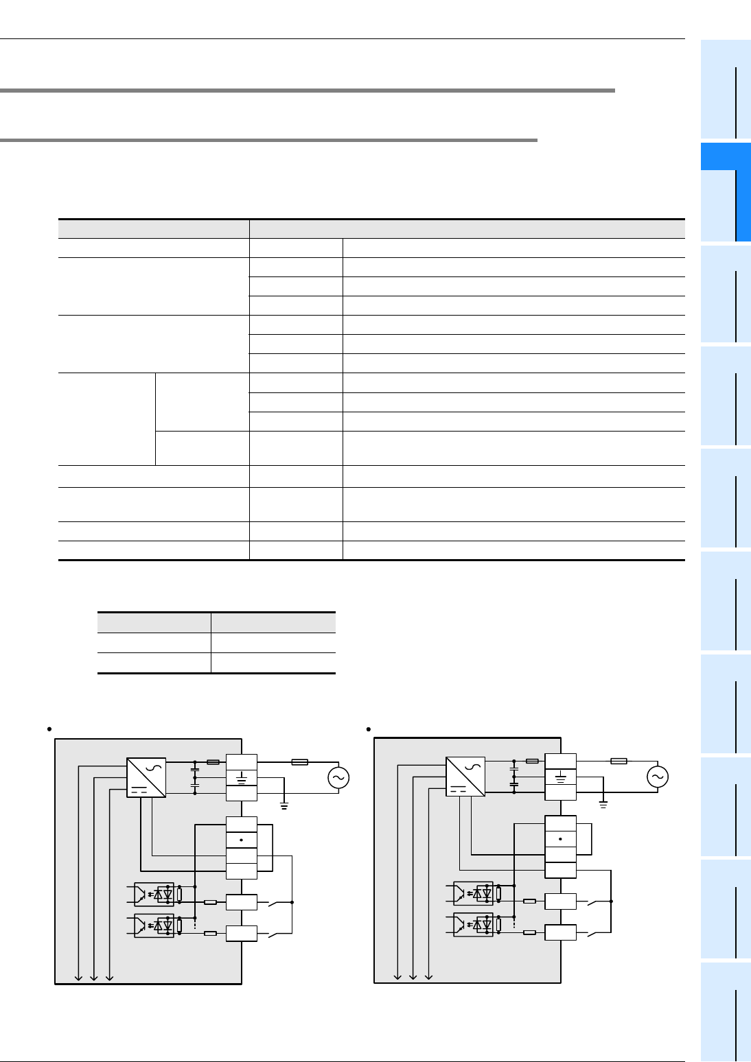
FX
3G
/FX
3U
/FX
3UC
PLC User's Manual - Positioning Control Edition
Built-in Positioning Functions
2 Specifications
2.4 Input Specifications
B - 19
A
Common Items
B
Built-in
Positioning
Functions
Apx.
Example
Connection
2.4 Input Specifications
2.4.1 FX3U Series main unit (24V DC Input)
This section describes the input specifications of the FX3U Series main unit. Note that the simultaneous
turning-on rate is restricted for the input extension units and the main unit. For details on this restriction, refer
to the following manual:
→ Refer to the FX3U Hardware Edition.
*1. If inputs X000 to X007 are assigned to the zero-phase signal of DSZR instruction or the interrupt input
of the DVIT the instruction, the input response time will be as shown in the following table.
1. Internal input circuit
Item 24V DC input specifications
Input signal voltage All inputs 24V DC±10%
Input impedance
X000 to X005 3.9kΩ
X006,X007 3.3kΩ
X010 or later 4.3kΩ
Input signal current
X000 to X005 6mA/24V DC
X006,X007 7mA/24V DC
X010 or later 5mA/24V DC
Input sensitivity
current
Input ON
current
X000 to X005 3.5 mA or more
X006,X007 4.5mA or more
X010 or later 3.5 mA or more
Input OFF
current All inputs 1.5mA or less
Input response time All inputs Approx. 10 ms*1
Input signal type All inputs No-voltage contact input
NPN/PNP open collector transistor
Circuit insulation All inputs Photocoupler insulation
Indication of input motion - Turning on the input will light the LED indicator lamp.
Input Input response time
X000 to X005 5µs
X006,X007 50µs
X0
S/S
0V
24V
Main unit
N
L
X1
24V 0V
Fuse
Class-D
grounding
Input
impedance
Sink input line connection
X0
S/S
0V
24V
Main unit
N
L
X1
24V 0V
Fuse
Class-D
grounding
Input
impedance
Source input line connection
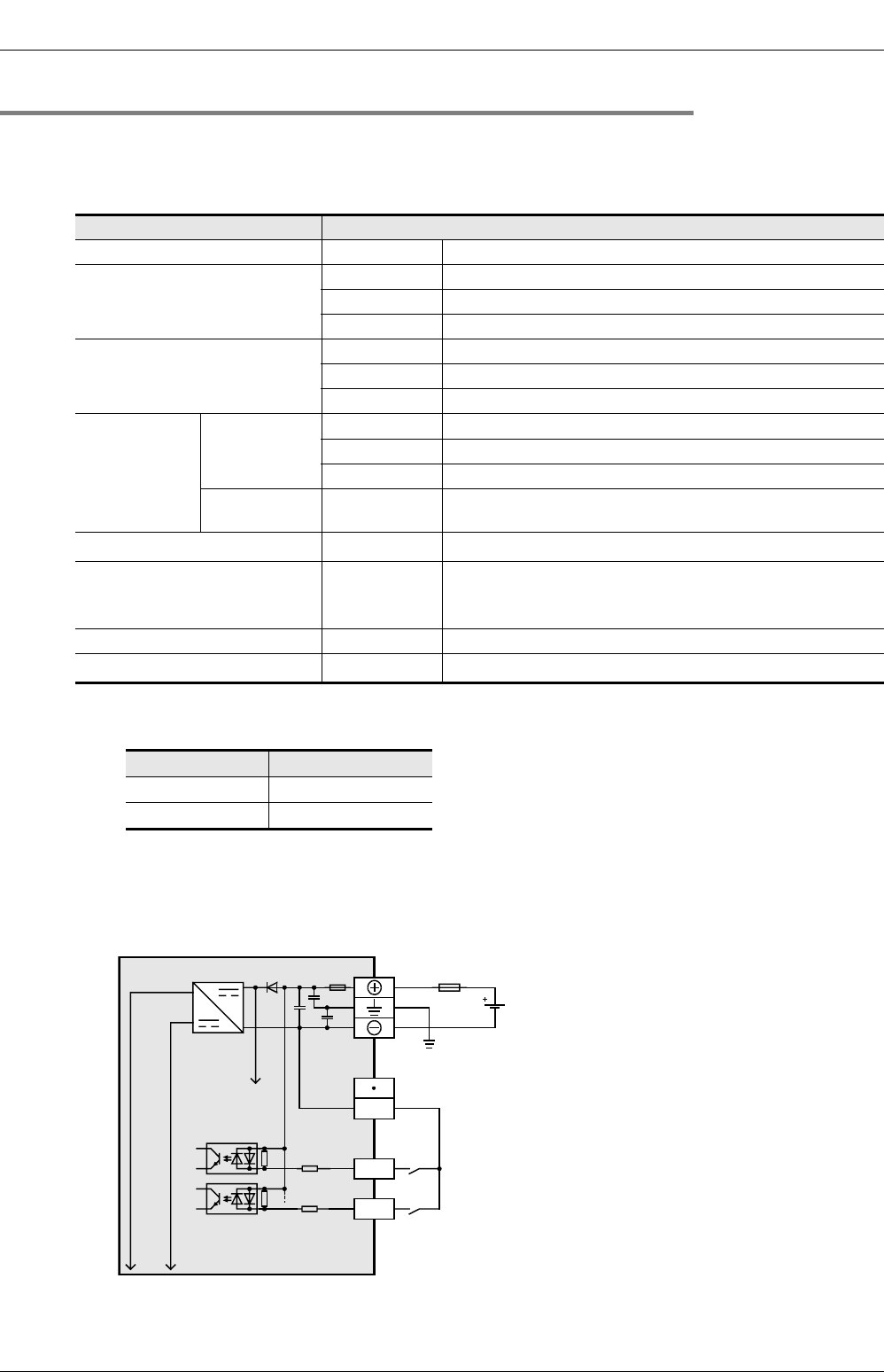
FX
3G
/FX
3U
/FX
3UC
PLC User's Manual - Positioning Control Edition
Built-in Positioning Functions
2 Specifications
2.4 Input Specifications
B - 20
2.4.2 FX3UC Series main unit (24V DC Input)
This section describes the input specifications of the FX3UC Series main unit. Note that the simultaneous
turning-on rate is restricted for the input extension units and the main unit. For details on this restriction, refer
to the following manual:
→ Refer to the FX3UC Hardware Edition.
*1. If inputs X000 to X007 are assigned to the zero-phase signal of the DSZR instruction or the interrupt
input of the DVIT instruction, the input response time will be as shown in the following table.
*2. PNP open collector transistors are supported only by the FX3UC-MT/DSS.
*3. The FX3UC-32MT-LT(-2) uses the display module for monitoring.
1. Internal input circuit
Item 24V DC input specifications
Input signal voltage All inputs 24V DC +20%, -15% / Ripple(p-p): 5 % or less
Input impedance
X000 to X005 3.9kΩ
X006,X007 3.3kΩ
X010 to X017 4.3kΩ
Input signal current
X000 to X005 6mA/24V DC
X006,X007 7mA/24V DC
X010 to X017 5mA/24V DC
Input sensitivity
current
Input ON
current
X000 to X005 3.5 mA or more
X006,X007 4.5mA or more
X010 to X017 3.5mA or more
Input OFF
current All inputs 1.5mA or less
Input response time All inputs Approx. 10 ms*1
Input signal type All inputs
No-voltage contact input
NPN open collector transistor
PNP open collector transistor*2
Circuit insulation All inputs Photocoupler insulation
Indication of input motion - Turning on the input will light the LED indicator lamp*3
Input Input response time
X000 to X005 5µs
X006, X007 50µs
X0
Main unit
X1
Fuse
Class-D grounding
Input impedance
24V DC
COM
·Sink input type(FX3UC- MT/D, FX3UC-32MT-LT(-2))
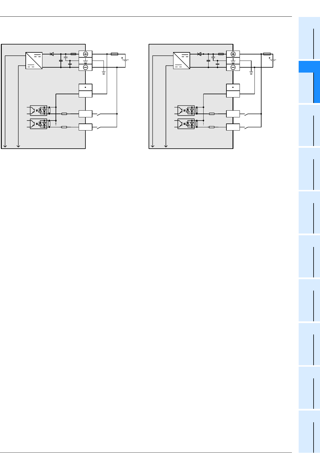
FX
3G
/FX
3U
/FX
3UC
PLC User's Manual - Positioning Control Edition
Built-in Positioning Functions
2 Specifications
2.4 Input Specifications
B - 21
A
Common Items
B
Built-in
Positioning
Functions
Apx.
Example
Connection
X0
Main unit
X1
Fuse
*
Input impedance
24V D
C
COM0
·
Source input type (FX
3UC
-
MT/DSS)
* Class-D grounding
X0
Main unit
X1
Fuse
*
Input impedance
24V DC
COM0
·
Sink input type(FX
3UC
-
MT/DSS)
* Class-D grounding
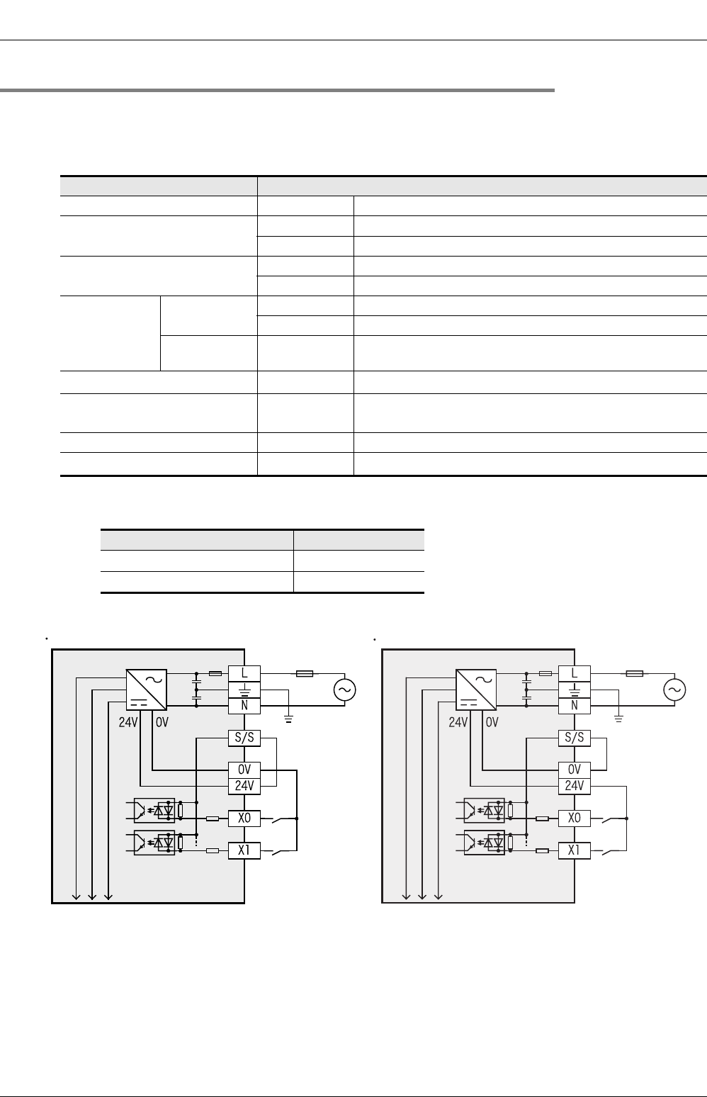
FX
3G
/FX
3U
/FX
3UC
PLC User's Manual - Positioning Control Edition
Built-in Positioning Functions
2 Specifications
2.4 Input Specifications
B - 22
2.4.3 FX3G Series main unit (24V DC Input)
This section describes the input specifications of the FX3G Series main unit. Note that the simultaneous
turning-on rate is restricted for the input extension units and the main unit. For details on this restriction, refer
to the following manual:
→ Refer to the FX3G Hardware Edition.
*1. If inputs X000 to X007 are assigned to the zero-phase signal of the DSZR instruction the input
response time will be as shown in the following table.
1. Internal input circuit
Item 24V DC input specifications
Input signal voltage All inputs 24V DC ±10%
Input impedance X000 to X007 3.3kΩ
X010 or more 4.3kΩ
Input signal current X000 to X007 7mA/24V DC
X010 or more 5mA/24V DC
Input sensitivity
current
Input ON
current
X000 to X007 4.5 mA or more
X010 or more 3.5mA or more
Input OFF
current All inputs 1.5mA or less
Input response time All inputs Approx. 10 ms*1
Input signal type All inputs No-voltage contact input
NPN/PNP open collector transistor
Circuit insulation All inputs Photocoupler insulation
Indication of input motion - Turning on the input will light the LED indicator lamp
Input Input response time
X000, X001, X003, X004 10µs
X002, X005 to X007 50µs
Sink input type
Main unit Fuse
Class-D
grounding
Input
impedance
Source input type
Main unit Fuse
Class-D
grounding
Input
impedance
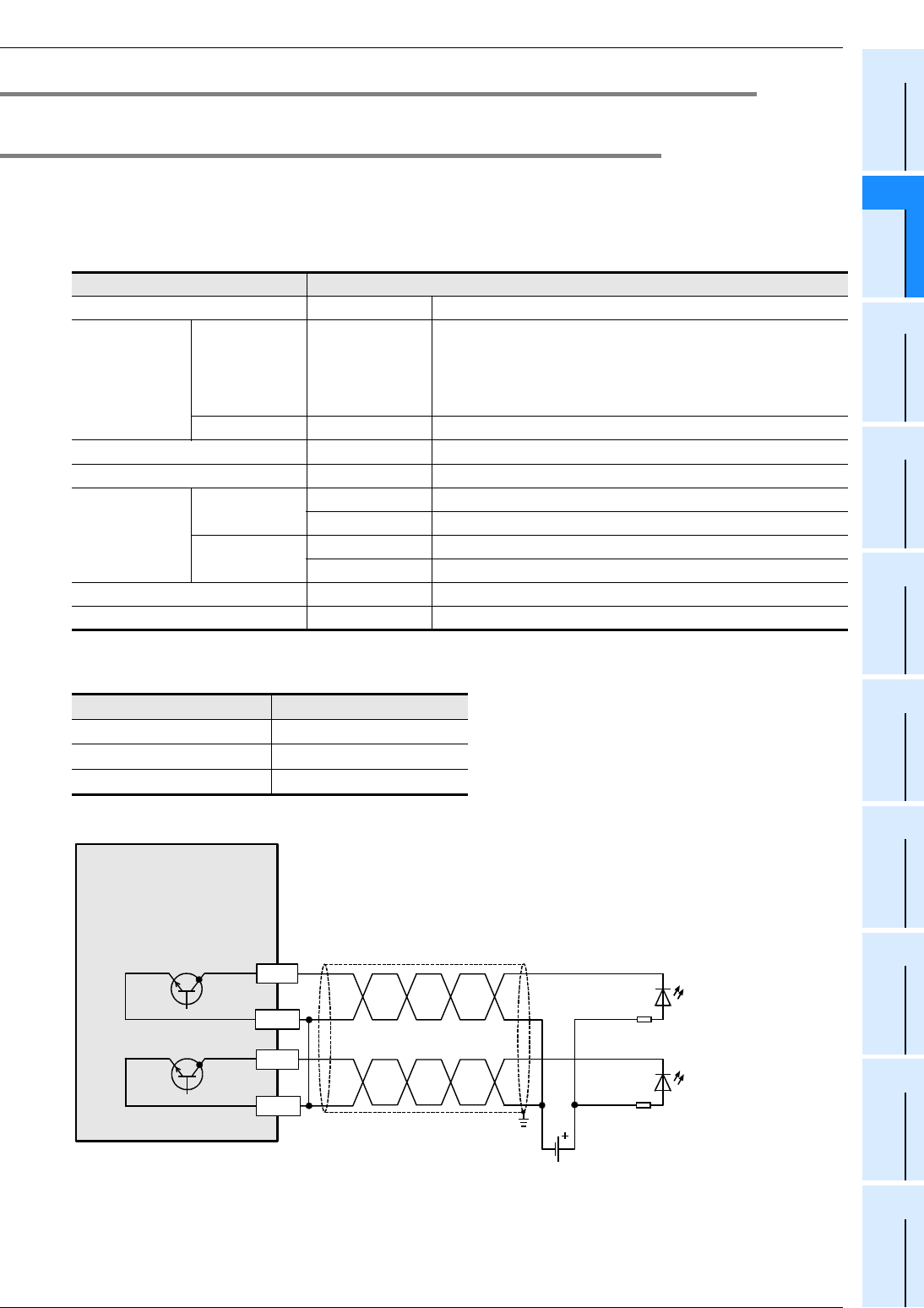
FX
3G
/FX
3U
/FX
3UC
PLC User's Manual - Positioning Control Edition
Built-in Positioning Functions
2 Specifications
2.5 Output Specifications
B - 23
A
Common Items
B
Built-in
Positioning
Functions
Apx.
Example
Connection
2.5 Output Specifications
2.5.1 FX3U Series main unit (Transistor Output)
This section describes the transistor output specifications of the FX3U Series main unit. Please note that the
simultaneous turning-on rate is restricted for the output extension units and the main unit. For details on the
restriction, refer to the following manual.
For MELSERVO Series amplifiers, use a sink input/sink output type PLC.
→ Refer to the FX3U Hardware Edition.
Pulse output terminals Y000, Y001, and Y002 are high-speed response output terminals.
To use the positioning instruction, adjust the load current of the NPN open collector to 10 to 100 mA (5 to 24V DC)
.
1. Sink internal output circuit
*1. To ground the unit, refer to the servo amplifier (drive unit) manual. If the grounding method is not
specified, carry out class-D grounding.
Item Transistor output specifications
External voltage All outputs 5 to 30V DC
Maximum load Resistance load All outputs
The total load current of resistance loads per common termi-
nal should be the following value or less.
- 1 point output common:0.5A
- 4 points output common:0.8A
- 8 points output common:1.6A
Inductive load All outputs 12W/24V DC
Open-circuit leakage current All outputs 0.1 mA or less at 30V DC
ON voltage All outputs 1.5V or less
Response time
OFF→ON Y000 to Y002 5 µs or less at 10 mA or more (5 to 24V DC)
Y003 and more 0.2 ms or less at 200 mA (at 24V DC)
ON→OFF Y000 to Y002 5 µs or less at 10 mA or more (5 to 24V DC)
Y003 and more 0.2 ms or less at 200 mA (at 24V DC)
Circuit insulation All outputs Photocoupler insulation
Indication of output motion - LED is lit when the photocoupler is driven.
Item Description
Operation voltage range 5 to 24V DC
Operation current range 10mA to 100mA
Output frequency 100 kHz or less
FX
3U
Series
main unit
Grounding
*1
Servo amplifier
(Drive unit)
5 to 24V DC
Pulse train signal
Direction signal
Y000
COM1
Y004
COM2
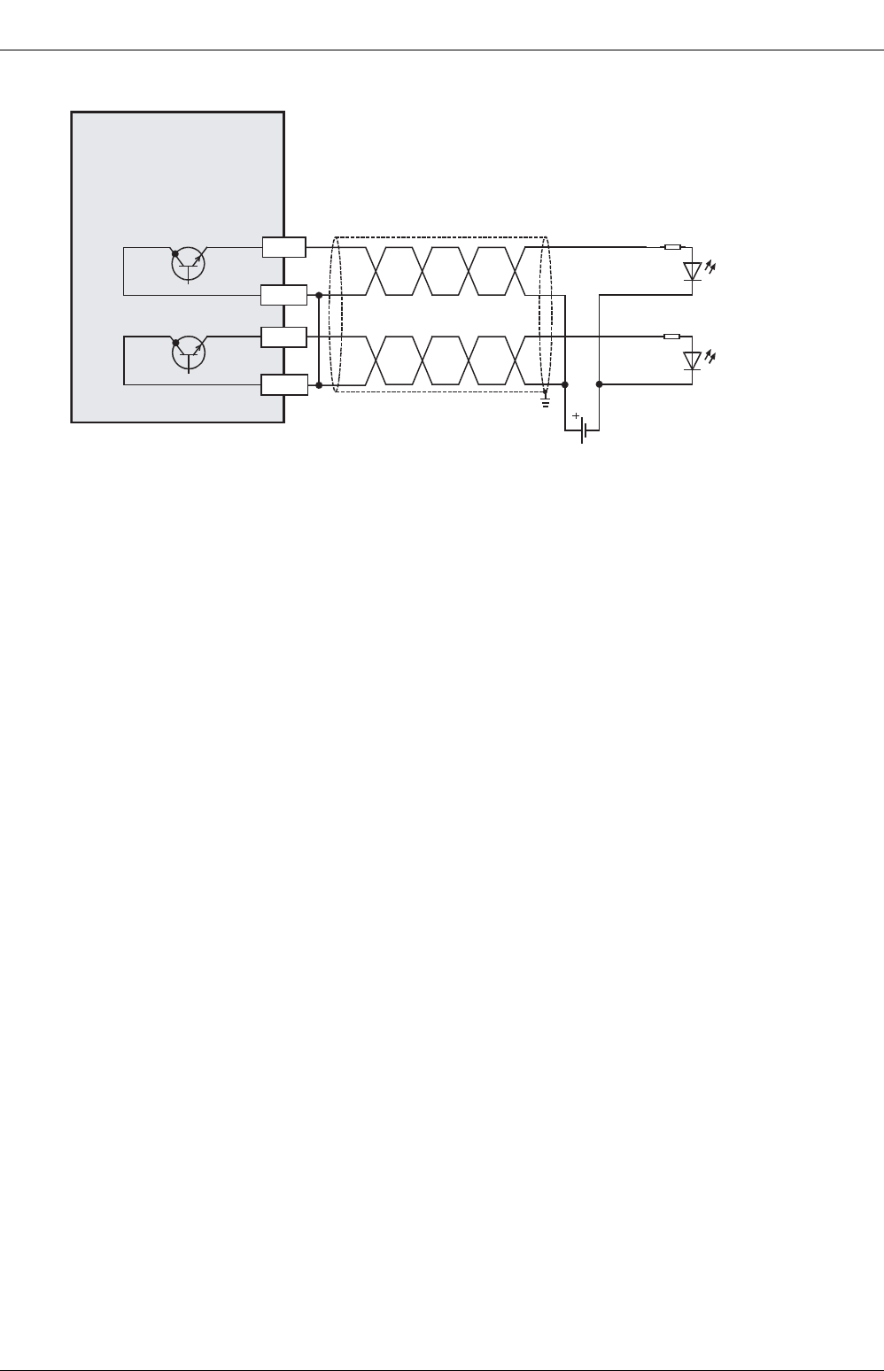
FX
3G
/FX
3U
/FX
3UC
PLC User's Manual - Positioning Control Edition
Built-in Positioning Functions
2 Specifications
2.5 Output Specifications
B - 24
2. Source internal output circuit
*1. To ground the unit, refer to the servo amplifier (drive unit) manual. If the grounding method is not
specified, carry out class-D grounding.
*2. For MELSERVO Series amplifiers, use a sink output type FX3U Series main unit.
FX
3U
Series
main unit
Grounding
*1 *2
Servo amplifier
(Drive unit)
5 to 24V DC
Pulse train signal
Direction signal
+V1
Y004
+V0
Y000
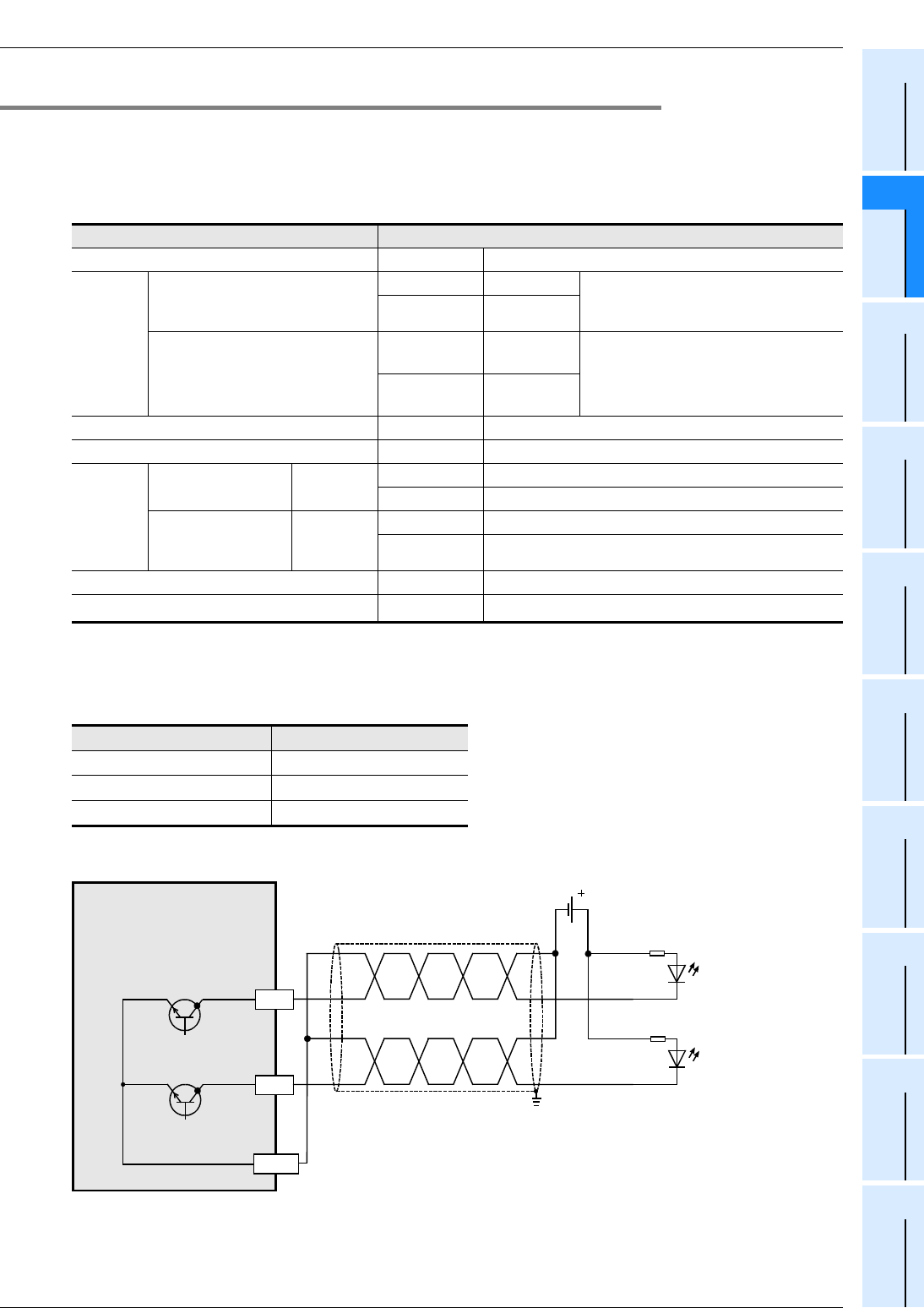
FX
3G
/FX
3U
/FX
3UC
PLC User's Manual - Positioning Control Edition
Built-in Positioning Functions
2 Specifications
2.5 Output Specifications
B - 25
A
Common Items
B
Built-in
Positioning
Functions
Apx.
Example
Connection
2.5.2 FX3UC Series main unit (Transistor Output)
This section describes the transistor output specifications of the FX3UC Series main unit. Note that the
simultaneous turning-on rate is restricted for the output extension units and the main unit. For details on this
restriction, refer to the following manual:
For MELSERVO Series amplifiers, use a sink input/sink output type PLC.
→ Refer to the FX3UC Hardware Edition.
*1. The FX3UC-32MT-LT(-2) uses the display module for monitoring.
Pulse output terminals Y000, Y001, and Y002 are high-speed response output terminals.
To use the positioning instruction, adjust the load current of the NPN open collector to 10 to 100 mA (5 to 24V DC)
.
1. Sink internal output circuit
*2. To ground the unit, refer to the servo amplifier (drive unit) manual. If the grounding method is not
specified, carry out class-D grounding.
Item Transistor output specifications
External voltage All outputs 5 to 30V DC
Maximum
load
Resistance load
Y000 to Y003 0.3 A/point The total load current of the common
items (16 points) should be 1.6 A or
less.
Y004 or more 0.1A/1point
Inductive load
Y000 to Y003 7.2W/1point
(24V DC) The total load of the common items
(16 points) should be 38.4 W or less at
24V DC.
Y004 or more 2.4W/1point
(24V DC)
Open-circuit leakage current All outputs 0.1 mA or less at 30V DC
ON voltage All outputs 1.5V or less
Response
time
FX3UC-32MT-LT
FX3UC-32MT-LT-2
OFF→ON
ON→OFF
Y000 to Y003 5 µs or less at 10 mA or more (5 to 24V DC)
Y004 to Y017 0.2 ms or less at 100 mA (at 24V DC)
FX3UC-MT/D
FX3UC-MT/
DSS
OFF→ON
ON→OFF
Y000 to Y002 5 µs or less at 10 mA or more (5 to 24V DC)
Y003 or more 0.2 ms or less at 100 mA (at 24V DC)
Circuit insulation All outputs Photocoupler insulation
Indication of output motion - LED is lit when the photocoupler is driven.*1
Item Description
Operation voltage range 5 to 24V DC
Operation current range 10mA to 100mA
Output frequency 100 kHz or less
Y0
Y4
FX3UC- MT/D
FX3UC-32MT-LT(-2)
Main unit
Grounding
*2
Servo amplifie
r
(Drive unit)
Pulse train signal
Direction signal
5 to 24V DC
COM1
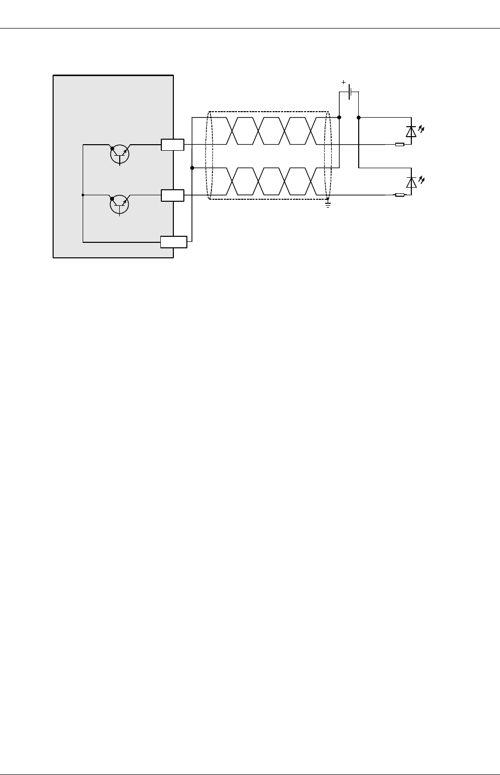
FX
3G
/FX
3U
/FX
3UC
PLC User's Manual - Positioning Control Edition
Built-in Positioning Functions
2 Specifications
2.5 Output Specifications
B - 26
2. Source internal output circuit
*1. To ground the unit, refer to the servo amplifier (drive unit) manual. If the grounding method is not
specified, carry out class-D grounding.
*2. For MELSERVO Series amplifiers, use a sink output type FX3UC Series main unit .
Y0
Y4
FX
3UC
-
MT/DSS
Main unit
Grounding
*1
Servo amplifier*2
(Drive unit)
Pulse train signal
Direction signal
5 to 24V DC
+V0
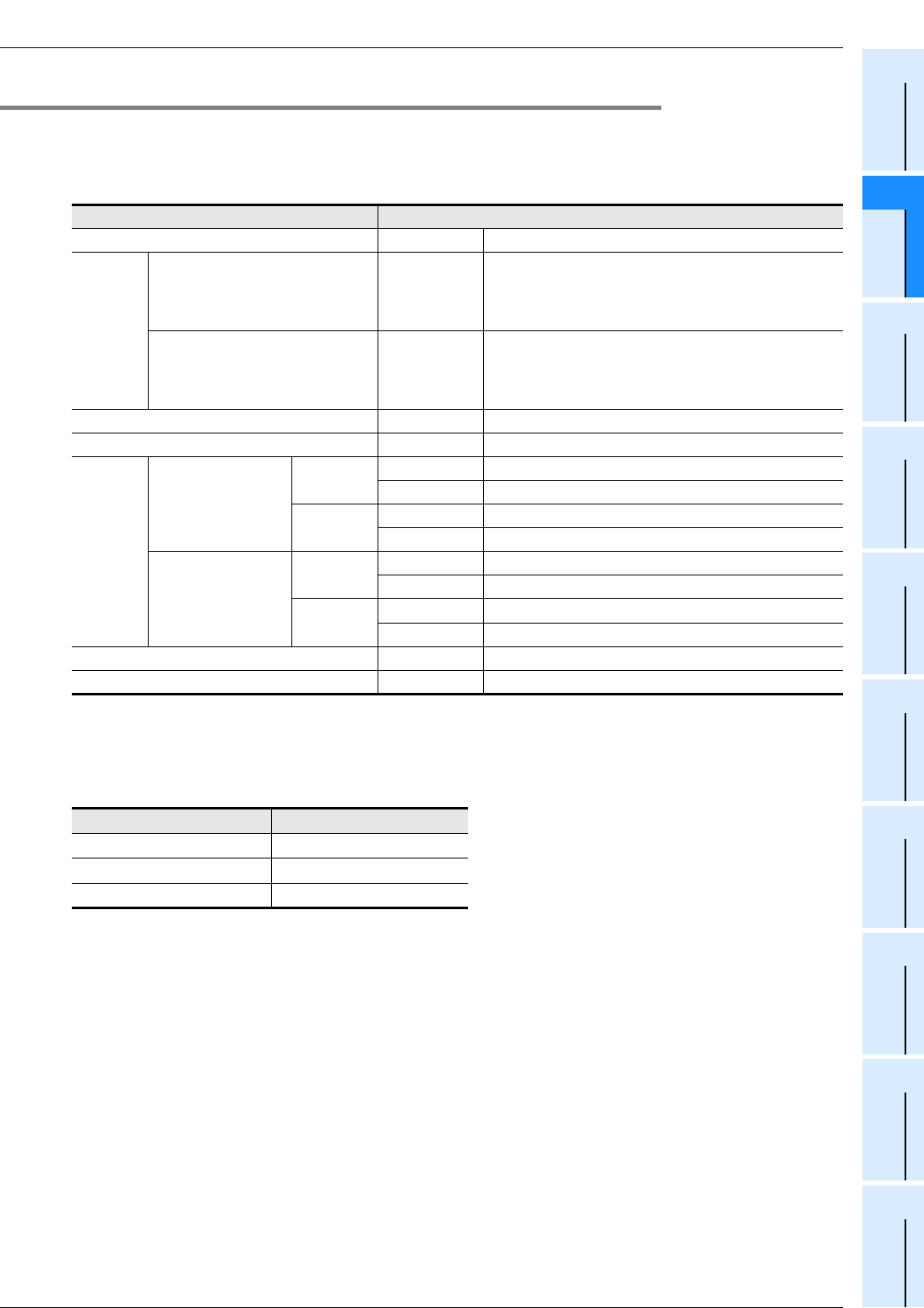
FX
3G
/FX
3U
/FX
3UC
PLC User's Manual - Positioning Control Edition
Built-in Positioning Functions
2 Specifications
2.5 Output Specifications
B - 27
A
Common Items
B
Built-in
Positioning
Functions
Apx.
Example
Connection
2.5.3 FX3G Series main unit (Transistor Output)
This section describes the transistor output specifications of the FX3G Series main unit. Note that the
simultaneous turning-on rate is restricted for the output extension units and the main unit. For details on this
restriction, refer to the following manual:
→ Refer to the FX3G Hardware Edition.
Pulse output terminals Y000, Y001, and Y002*1 are high-speed response output terminals.
To use the positioning instruction, adjust the load current of the NPN open collector to 10 to 100 mA (5 to 24V DC).
*1. Y002 works as a high-speed response pulse output terminal only in 40-point and 60-point type main
units.
Item Transistor output specifications
External voltage All outputs 5 to 30V DC
Maximum
load
Resistance load All outputs
The total load current of resistance loads per common
terminal should be the following value or less.
- 1 point output common:0.5A
- 4 points output common:0.8A
Inductive load All outputs
The total of inductive loads per common terminal
should be the following value or less.
- 1 point output common:12W/24V DC
- 4 points output common:19.2W/24V DC
Open-circuit leakage current All outputs 0.1 mA or less at 30V DC
ON voltage All outputs 1.5V or less
Response
time
14-point, 24-point
type
OFF→ON Y000, Y001 5 µs or less at 10 mA or more (5 to 24V DC)
Y002 or more 0.2 ms or less at 200 mA or more (at 24V DC)
ON→OFF Y000, Y001 5 µs or less at 10 mA or more (5 to 24V DC)
Y002 or more 0.2 ms or less at 200 mA or more (at 24V DC)
40-point, 60-point
type
OFF→ON Y000 to Y002 5 µs or less at 10 mA or more (5 to 24V DC)
Y003 or more 0.2 ms or less at 200 mA or more (at 24V DC)
ON→OFF Y000 to Y002 5 µs or less at 10 mA or more (5 to 24V DC)
Y003 or more 0.2 ms or less at 200 mA or more (at 24V DC)
Circuit insulation All outputs Photocoupler insulation
Indication of output motion - LED is lit when the photocoupler is driven.
Item Description
Operation voltage range 5 to 24V DC
Operation current range 10mA to 100mA
Output frequency 100 kHz or less
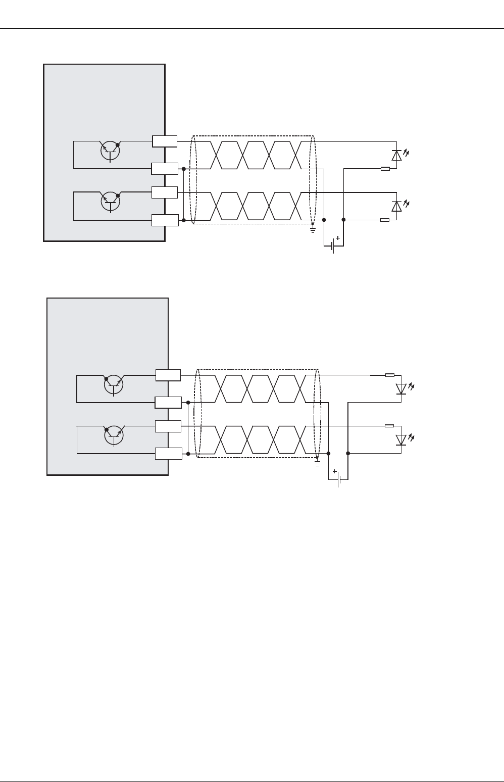
FX
3G
/FX
3U
/FX
3UC
PLC User's Manual - Positioning Control Edition
Built-in Positioning Functions
2 Specifications
2.5 Output Specifications
B - 28
1. Sink internal output circuit
2. Source internal output circuit
*1. To ground the unit, refer to the servo amplifier (drive unit) manual. If the grounding method is not
specified, carry out class-D grounding.
*2. For MELSERVO Series amplifiers, use a sink output type FX3G Series main unit.
Grounding
*1
Servo amplifie
r
(Drive unit)
5 to 24V DC
Pulse train signal
Direction signal
Y000
COM0
Y004
COM3
FX
3G
Series
main unit
Grounding
*1 *2
Servo amplifier
(Drive unit)
5 to 24V DC
Pulse train signal
Direction signal
+V3
Y004
+V0
Y000
FX3G Series
main unit
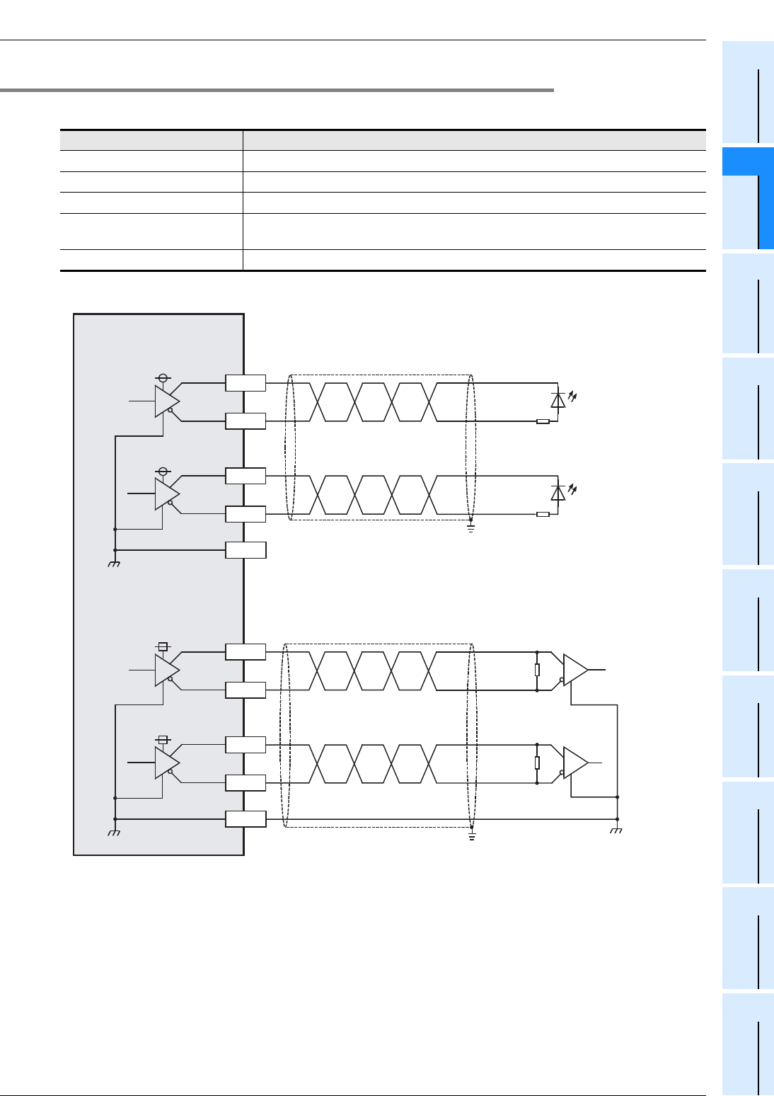
FX
3G
/FX
3U
/FX
3UC
PLC User's Manual - Positioning Control Edition
Built-in Positioning Functions
2 Specifications
2.5 Output Specifications
B - 29
A
Common Items
B
Built-in
Positioning
Functions
Apx.
Example
Connection
2.5.4 High-Speed Output Special Adapter [FX3U-2HSY-ADP]
This section describes the output specifications of the high-speed output special adapter (FX3U-2HSY-ADP).
1. Internal output circuit
*1. To ground the unit, refer to the servo amplifier (drive unit) manual. If the grounding method is not
specified, carry out class-D grounding.
*2. The line between the SGA and the SGB is insulated.
Item High-speed output special adapter (FX3U-2HSY-ADP)
Output system Differential line driver system (equivalent to AM26C31)
Load current 25 mA or less
Maximum output frequency 200KHz
Insulation Photocoupler and transformer insulate PLC from external lines of its outputs, and
transformer insulates each SG.
Cable length 10 m, maximum
Y0/2+
SGA
High-speed output
special adapter
FX
3U
-2HSY-ADP
Y0/2-
Y4/6+
Y4/6-
Equivalent to
AM26C31
Grounding
*1
Servo amplifier
(Drive unit)
•To connect to photocoupler:
Pulse train,
forward rotation pulse train
Direction signal, reverse
rotation pulse train
Y1/3+
SGB
Y1/3-
Y5/7+
Y5/7-
Equivalent to
AM26C31
Grounding
*1
Servo amplifier
(Drive unit)
•To connect to differential line receiver:
Pulse train,
forward rotation pulse train
Direction signal, reverse
rotation pulse train
SGA
*2
SGB
*2
5V
5V
5V
5V
FX
3G
/FX
3U
/FX
3UC
PLC User's Manual - Positioning Control Edition
Built-in Positioning Functions
2 Specifications
2.6 List of Functions
B - 30
2.6 List of Functions
The instructions needed for the FX
3G
/FX
3U
/FX
3UC
PLC built-in positioning functions are shown in the following
table:
Positioning instruction Operation Description Refer to
Mechanical zero return
DSZR
instruction
zero return
with DOG
search
function
If the DSZR/ZRN instruction turns ON,
mechanical zero return will be started at
the specified zero return speed. If the dog
sensor is turned on, the speed will be
reduced to the creep speed. If the zero-
phase signal is input, the operation will be
stopped, and the zero return will be
completed.
(If the ZRN instruction is used, the dog
sensor will be turned off to stop the
operation.)
Chapter
6.
ZRN
instruction zero return
Absolute position detection system
ABS
instruction
Absolute
value detec-
tion system
(Reading of
current ABS
value)
If the ABS instruction turns ON, the
current motor address will be read out
from the servo amplifier.
Chapter
7.
1-speed positioning
DRVI
instruction
Relative
positioning
If the DRVI/DRVA instruction turns ON,
the operation will be started at the
operation speed. When the workpiece
reaches the target position, the operation
will be stopped.
Chapter
8.
DRVA
instruction
Absolute
positioning
1-speed positioning with interruption
DVIT
instruction
*1
Interruption
positioning
If the DVIT instruction turns ON, the
operation will be started at the operation
speed. If the interrupt input turns ON, the
workpiece will go the specified transfer
distance, before decelerating to stop.
Chapter
9.
Variable speed operation
PLSV
instruction
Variable
positioning
(Variable
Speed Pulse
Output)
If the PLSV instruction turns ON,
operation will be started at the specified
speed. With an operation speed change,
the speed changes to the specified speed,
and operation continues.
At PLSV instruction OFF, the pulse output
stops.
With acceleration/deceleration operation,
the PLC accelerates and decelerates.
Chapter
10.
Others
TBL
instruction
*2
Positioning
using batch
setting
method
Preliminarily set the positioning points by
parameters. If the TBL instruction turns
ON, the workpiece will be transferred to
the specified point.
Chapter
11.
Speed
StartDOG:ONZero point: ON
Zero return
speed
Creep
speed
(Dog: OFF when ZRN
instruction is used)
Reads out the
current value.
Speed
Start Target position
Operation speed
Transfer distance
Speed
Start Interrupt
input: ON
Operation speed
Transfer
distance
Speed
Start Speed
change
Operation speed
Speed
change Instruction:
OFF
Operation speed
Speed
Start Speed
change Speed
change Instruction:
OFF
Operation without
A
cceleration/Deceleration
Operation with
A
cceleration/Deceleration*
2
Position Speed InstructionNo.
1
2
3
4
1000
20000
50
800
2000
5000
1000
10000
DRVI
DVIT
DRVA
DRVA

FX
3G
/FX
3U
/FX
3UC
PLC User's Manual - Positioning Control Edition
Built-in Positioning Functions
2 Specifications
2.6 List of Functions
B - 31
A
Common Items
B
Built-in
Positioning
Functions
Apx.
Example
Connection
*1. Only available for FX3U and FX3UC PLCs.
*2. Only available for FX3U/FX3UC PLC Ver. 2.20 or later and FX3G PLC.

3 Connection of Input/Output Lines and Tightening
B - 32
FX
3G
/FX
3U
/FX
3UC
PLC User's Manual - Positioning Control Edition
Built-in Positioning Functions
3. Connection of Input/Output Lines and Tightening Torques
This chapter describes how to connect the input/output lines and the terminal tightening torques.
WIRING PRECAUTIONS
• Make sure to cut off all phases of the power supply externally before attempting installation or wiring work.
Failure to do so may cause electric shock or damage to the product.
• Make sure to attach the terminal cover, offered as an accessory, before turning on the power or initiating operation
after installation or wiring work.
Failure to do so may cause electric shock.
WIRING PRECAUTIONS
• Connect the AC power supply to the dedicated terminals specified in the manual of the PLC main unit.
If an AC power supply is connected to a DC input/output terminal or DC power supply terminal, the PLC will burn
out.
• Connect the DC power supply to the dedicated terminals specified in the manual of the PLC main unit.
If an AC power supply is connected to a DC input/output terminal or DC power supply terminal, the PLC will burn
out.
• Do not wire vacant terminals externally.
Doing so may damage the product.
• Perform class D grounding (grounding resistance: 100Ω or less) to the grounding terminal on the FX3U/FX3G PLC
main unit with a wire 2 mm2 or thicker.
Do not use common grounding with heavy electrical systems (refer to the manual of the PLC main unit).
• Perform class D grounding (grounding resistance: 100Ω or less) to the grounding terminal on the main unit.
Do not use common grounding with heavy electrical systems.
• When drilling screw holes or wiring, make sure cutting or wire debris does not enter the ventilation slits.
Failure to do so may cause fire, equipment failures or malfunctions.
• Install module so that excessive force will not be applied to I/O connectors.
Failure to do so may result in wire damage/breakage or PLC failure.
• Connect input/output cables securely to their designated connectors.
Loose connections may cause malfunctions.
• Make sure to properly wire the FX3U/FX3G Series main unit and FX0N/FX2N Series extension equipment in
accordance with the following precautions.
Failure to do so may cause electric shock, a short-circuit, wire breakage, or damage to the product.
- The disposal size of the cable end should follow the dimensions described in this manual.
- Tightening torque should be between 0.5 and 0.8 N•m.
• Make sure to properly wire to the European terminal board in accordance with the following precautions.
Failure to do so may cause electric shock, a short-circuit, wire breakage, or damage to the product.
- The disposal size of the cable end should follow the dimensions described in this manual.
- Tightening torque should be between 0.22 and 0.25 N•m.
- Twist the end of strand wire and make sure that there are no loose wires.
- Do not solder-plate the electric wire ends.
- Do not connect more than the specified number of wires or electric wires of unspecified size.
- Affix the electric wires so that neither the terminal block nor the connected parts are directly stressed.
• Make sure to properly wire to the FX Series terminal blocks in accordance with the following precautions.
Failure to do so may cause electric shock, a short-circuit, wire breakage, or damage to the product.
- The disposal size of the cable end should follow the dimensions described in this manual.
- Tightening torque should be between 0.5 and 0.8 N•m.
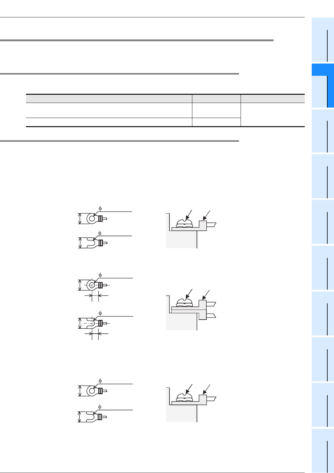
3 Connection of Input/Output Lines and Tightening
3.1 Terminal Board (M3, M3.5)
B - 33
FX
3G
/FX
3U
/FX
3UC
PLC User's Manual - Positioning Control Edition
Built-in Positioning Functions
A
Common Items
B
Built-in
Positioning
Functions
Apx.
Example
Connection
3.1 Terminal Board (M3, M3.5)
A terminal board is used for the FX3U, FX3G Series main unit, FX2N Series input/output extension unit
(excluding some types), and FX0N Series input/output extension block.
3.1.1 Terminal Screw Size
The terminal screw size of each product is shown in the following table. For details on the crimp-style
terminals, refer to Subsection 3.1.2.
3.1.2 Termination
The size of each crimp-style terminal depends on the size of the terminal screw and the wiring method.
Refer to the following description to select a crimp-style terminal of optimum size.
1. FX3U, FX3G Series main unit,
FX2N Series input/output powered extension unit, and FX0N Series input/output extension
block
• When one wire is connected to one terminal
• When two wires are connected to one terminal
2. FX Series terminal block
• When one wire is connected to one terminal
Product Terminal screw Tightening torque
FX3U, FX3G Series main unit, FX2N Series input/output powered
extension unit, FX2N/FX0N Series input/output extension block M3 0.5 to 0.8N•m
FX Series terminal block M3.5
TerminalTerminal
Terminal
screw Crimp
terminal
6.2mm(0.24")
or less
3.2(0.13")
6.2mm(0.24")
or less
3.2(0.13")
Terminal
screw Crimp
terminal
Terminal
6.2mm(0.24")
or less
3.2(0.13")
6.3mm(0.25")
or more
6.2mm(0.24")
or less
3.2(0.13")
6.3mm(0.25")
or more
6.8mm(0.27")
or less
3.7(0.15")
TerminalTerminal
Terminal
screw Crimp
terminal
6.8mm(0.27")
or less
3.7(0.15")
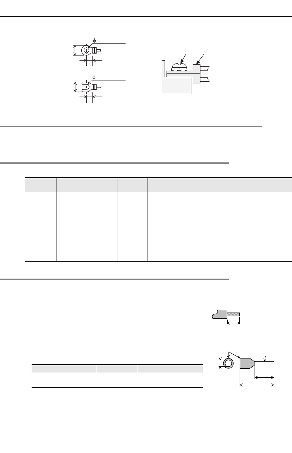
3 Connection of Input/Output Lines and Tightening
3.2 European Terminal Board
B - 34
FX
3G
/FX
3U
/FX
3UC
PLC User's Manual - Positioning Control Edition
Built-in Positioning Functions
• When two wires are connected to one terminal
3.2 European Terminal Board
The European terminal board is used for the high-speed output special adapter and the FX2NC Series input/
output extension block.
3.2.1 Cable
Applicable cables and tightening torques
3.2.2 Termination of Cable End
Directly terminate the end of each stranded cable or single-wire cable without a tool, or use the rod terminal
with insulation sleeve for termination.
• Directly terminate the end of the stranded/single-wire cable:
- Terminate the end of the stranded cable so that "barbed wires"
cannot protrude.
- Do not solder-plate the end of the cable.
• Terminate the cable end using a rod terminal with insulation sleeve:
If the cable sheath is too thick, it may be difficult to insert the cable
into the insulation sleeve. For this reason, select an appropriate cable
while referring to the external view.
Wire size (stranded/
single wire)
Tightening
torque Termination
Single-wire 0.3 mm2 to 0.5 mm2
(AWG22 to 20)
0.22 to
0.25 N•m
• To connect a stranded cable, peel the sheath off the cable,
and then twist the core before connection.
• To connect a single-wire cable, just peel the sheath off the
cable before connection.
2-wires 0.3 mm2(AWG22)
Rod
terminal
with
insulation
sleeve
0.3 mm2 to 0.5 mm2
(AWG22-20)
(Refer to the external
view of the rod terminal
shown in the following
figure.)
• Rod terminal with insulation sleeve
(recommended terminal)
AI 0.5-8WH: Manufactured by Phoenix Contact
• Caulking tool:
CRIMPFOX ZA 3: Manufactured by Phoenix Contact
(or CRIMPFOX UD 6: Manufactured by Phoenix Contact)
Manufacturer Model Caulking tool
Phoenix Contact AI 0.5-8WH CRIMPFOX ZA 3
(or CRIMPFOX UD 6)
6.8mm(0.27")
or less
3.7(0.15")
6.0mm(0.24")
or more
Terminal
screw Crimp
terminal
Terminal
6.8mm(0.27")
or less
3.7(0.15")
6.0mm(0.24")
or more
9mm
(0.36")
•
Stranded wire/solid wire
8mm
(0.32")
Contact portion
(Crimp area)
14mm(0.56")
2.6mm
(0.11")
Insulating sleeve
•
Bar terminal with insulating sleeve
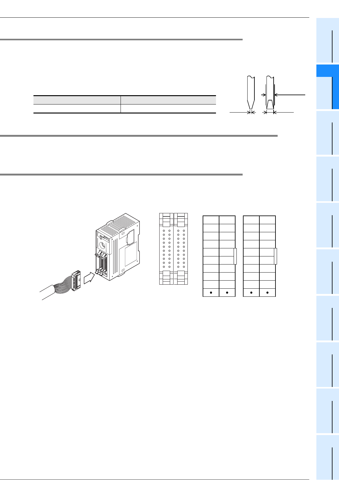
3 Connection of Input/Output Lines and Tightening
3.3 Connector
B - 35
FX
3G
/FX
3U
/FX
3UC
PLC User's Manual - Positioning Control Edition
Built-in Positioning Functions
A
Common Items
B
Built-in
Positioning
Functions
Apx.
Example
Connection
3.2.3 Tool
• To tighten the terminals, use a purchased small-sized screwdriver whose tip is straight and is not widened
as shown in the right figure.
Note:
If the diameter of screwdriver grip is too small, tightening torque will not
be able to be achieved. Use the following recommended screwdriver or
an appropriate replacement (grip diameter: approximately 25mm).
3.3 Connector
Connectors conforming to the requirements of the MIL C-83503 are used for the FX3UC Series main unit
along with some types of FX2NC Series input/output extension blocks.
3.3.1 Cable Connection To Input/Output Connector
Prepare the input/output cables while referring to the next Subsection.
Example : FX3UC-32MT/D Main unit
Manufacturer Model
Phoenix Contact SZS 0.4×2.5
0.4mm
(0.02")
2.5mm
(0.1")
With
straight tip
X0
X1
X2
X3
X4
X5
X6
X7
COM
X10
X11
X12
X13
X14
X15
X16
X17
COM
Y0
Y1
Y2
Y3
Y4
Y5
Y6
Y7
COM1
Y10
Y11
Y12
Y13
Y14
Y15
Y16
Y17
COM1
Input Output
*1 *1 *1 *1
*1: "
•
" means that the terminal is not used.
Input: X Output: Y

3 Connection of Input/Output Lines and Tightening
3.3 Connector
B - 36
FX
3G
/FX
3U
/FX
3UC
PLC User's Manual - Positioning Control Edition
Built-in Positioning Functions
3.3.2 Setup of Input/Output Connection Connector
1. Applicable connector (connector purchased at store)
Use a 20-pin (1-key) socket that conforms to the requirements of the MIL C-83503.
Preliminarily check that the peripheral parts, such as the connector cover, will not cause any interference.
2. Input/output cables (optional cables manufactured by our company)
Mitsubishi Electric can provide input/output cables already equipped with a connector.
3. Input/output cable connectors prepared by purchaser (optional connectors manufactured
by Mitsubishi Electric)
The purchaser should prepare the cables and press-fitting tools.
Model Length Description Connector type
FX-16E-500CAB-S 5m
(16’ 4") General-purpose input/output cable • Single wire (Wire color: red)
• PLC side: A 20-pin connector
FX-16E-150CAB 1.5m
(4’11")
Cable for connection of FX Series
terminal block to input/output connector
For details on connection to the FX
Series terminal block, refer to the
following manuals:
→FX3G Hardware Edition
→FX3U Hardware Edition
→FX3UC Hardware Edition
• Flat cables (with tube)
• A 20-pin connector at both ends
FX-16E-300CAB 3m
(9’10")
FX-16E-500CAB 5m
(16’ 4")
FX-16E-150CAB-R 1.5m
(4’11")
• Round multicore cables
• A 20-pin connector at both ends
FX-16E-300CAB-R 3m
(9’10")
FX-16E-500CAB-R 5m
(16’ 4")
FX-A32E-150CAB 1.5m
(4’11") Cable for connection of A Series
A6TBXY36 connector/terminal board
conversion unit to input/output
connector type
• Flat cables (with tube)
• PLC side: Two 20-pin connectors
in 16-point units
• Terminal block side: A dedicated
connector
• One common terminal covers 32
input/output terminals
FX-A32E-300CAB 3m
(9’10")
FX-A32E-500CAB 5m
(16’ 4")
Input/output connector model and number
of connectors included in one set
Applicable cable
(recommended cable: UL-1061) and tool
Our model
Description of parts
(Manufactured by Daiichi
Denshi Kogyo Co., Ltd.)
Cable size
Crimping tool
(Manufactured by Daiichi
Denshi Kogyo Co., Ltd.)
FX2C-I/O-CON,for flat
cable
Set of
10 parts
Crimp-style connector
FRC2-A020-30S
AWG28(0.1 mm2)
1.27 pitch, 20 cores
357J-4674D main unit
357J-4664N attachment
FX2C-I/O-CON-S, for
non-stranded cable 5 sets
Housing HU-200S2-001
Crimp-style contact HU-
411S
AWG22(0.3mm2)357J-5538
FX2C-I/O-CON-SA,
for non-stranded
cable
5 sets
Housing HU-200S2-001
Crimp-style contact HU-
411SA
AWG20(0.5mm2)357J-13963

3 Connection of Input/Output Lines and Tightening
3.3 Connector
B - 37
FX
3G
/FX
3U
/FX
3UC
PLC User's Manual - Positioning Control Edition
Built-in Positioning Functions
A
Common Items
B
Built-in
Positioning
Functions
Apx.
Example
Connection
4. Connector already confirmed as applicable (sold at store)
Connectors manufactured by Daiichi Denshi Kogyo Co., Ltd. (shown in 3) and connectors manufactured by
Matsushita Electric Works, Ltd. (shown in following table)
Connector model Applicable cable
(recommended cable: UL-1061) Crimping tool
Housing AXW1204A
AWG22(0.3mm2)
AWG24(0.2mm2)AXY52000Contact AXW7221
Semi-cover AXW62001A

FX
3G
/FX
3U
/FX
3UC
PLC User's Manual - Positioning Control Edition
Built-in Positioning Functions
4 Before Programming
4.1 List of Related Devices
B - 38
4. Before Programming
This chapter describes several items that should be known before programming. They are:
• Operation of related devices, such as output pulse frequency, operation command flag, current value, and
operation monitor flag.
• Items to be set on the PLC side
• Items to be set on the servo amplifier (drive unit) side
• Items to be observed in programming
4.1 List of Related Devices
→ For details on related devices, refer to Section 4.2 to Section 4.4.
4.1.1 Special Auxiliary Relays
The following table shows the related special auxiliary relays. Note that Y000, Y001, Y002, and Y003 are
devices that determine the pulse output destinations.
→ For details on the PLSY (FNC 57), PWM (FNC 58), and PLSR (FNC 59) instructions, refer to the
programming manual.
Device number Function Attribute Corresponding
instructions Refer to
Y000 Y001 Y002*6 Y003*1
M8029 "Instruction execution complete"
flag Read only
PLSY,PLSR,DSZR,
DVIT,ZRN,PLSV,
DRVI,DRVA
and so on.
Subsection
4.4.2
M8329 "Instruction execution abnormal
end" flag Read only
PLSY,PLSR,DSZR,
DVIT,ZRN,PLSV,
DRVI,DRVA
Subsection
4.4.2
M8338*2 Acceleration/deceleration
Operation*3 Drivable PLSV
Subsection
4.3.9
M8336*4 Interrupt input specification function
enable*3 Drivable DVIT
Subsection
4.3.7
M8340 M8350 M8360 M8370 "Pulse output monitor" flag
(BUSY/READY) Read only
PLSY,PLSR,DSZR,
DVIT,ZRN,PLSV,
DRVI,DRVA
Subsection
4.4.3
M8341 M8351 M8361 M8371 CLEAR signal output function
enable*3 Drivable DSZR,ZRN
Subsection
4.3.4
M8342 M8352 M8362 M8372 Zero return direction specification*3 Drivable DSZR
Subsection
4.3.3
M8343 M8353 M8363 M8373 Forward limit Drivable PLSY,PLSR,DSZR,
DVIT,ZRN,PLSV,
DRVI,DRVA
Subsection
4.3.1
M8344 M8354 M8364 M8374 Reverse limit Drivable
Subsection
4.3.1
M8345 M8355 M8365 M8375 DOG signal logic reverse*3 Drivable DSZR
Subsection
4.3.5
M8346 M8356 M8366 M8376 Zero point signal logic reverse*3 Drivable DSZR
Subsection
4.3.6
*1. Devices related to Y003 (pulse output destination) are only valid if two FX3U-2HSY-ADP adapters are connected to the
FX3U PLC.
*2. Only available for FX3U/FX3UC PLC Ver. 2.20 or later and FX3G PLC.
*3. Cleared when PLC switches from RUN to STOP.
*4. Only available for FX3U/FX3UC PLC Ver. 1.30 or later.
*5. For the user interrupt input command, the logical NOT function will not be activated.
*6. Y002 (pulse output destination) cannot be specified when the 14-point or 24-point type FX3G PLC is connected.
*7. Only available for FX3U and FX3UC PLC Ver.2.20 or later.

FX
3G
/FX
3U
/FX
3UC
PLC User's Manual - Positioning Control Edition
Built-in Positioning Functions
4 Before Programming
4.1 List of Related Devices
B - 39
A
Common Items
B
Built-in
Positioning
Functions
Apx.
Example
Connection
M8347 M8357 M8367 M8377 Interrupt signal logic reverse*3,*5 Drivable DVIT
Subsection
4.3.8
M8348 M8358 M8368 M8378 Positioning instruction activation Read only
PLSY,PWM,PLSR,
DSZR,DVIT,ZRN,
PLSV,DRVI,DRVA
Subsection
4.4.4
M8349 M8359 M8369 M8379 Pulse output stop command*3 Drivable
PLSY,PLSR,DSZR,
DVIT,ZRN,PLSV,
DRVI,DRVA
Subsection
4.3.2
M8460
*7
M8461
*7
M8462
*7
M8463
*7
User interrupt input command*3 Drivable DVIT
Subsection
4.3.7
M8464
*2
M8465
*2
M8466
*2
M8467
*2
CLEAR signal device specification
function enable*3 Drivable DSZR,ZRN
Subsection
4.3.4
Device number Function Attribute Corresponding
instructions Refer to
Y000 Y001 Y002*6 Y003*1
*1. Devices related to Y003 (pulse output destination) are only valid if two FX3U-2HSY-ADP adapters are connected to the
FX3U PLC.
*2. Only available for FX3U/FX3UC PLC Ver. 2.20 or later and FX3G PLC.
*3. Cleared when PLC switches from RUN to STOP.
*4. Only available for FX3U/FX3UC PLC Ver. 1.30 or later.
*5. For the user interrupt input command, the logical NOT function will not be activated.
*6. Y002 (pulse output destination) cannot be specified when the 14-point or 24-point type FX3G PLC is connected.
*7. Only available for FX3U and FX3UC PLC Ver.2.20 or later.

FX
3G
/FX
3U
/FX
3UC
PLC User's Manual - Positioning Control Edition
Built-in Positioning Functions
4 Before Programming
4.1 List of Related Devices
B - 40
4.1.2 Special Data Registers
The following table shows the related special data registers. Note that Y000, Y001, Y002, and Y003 are
devices that determine the pulse output destinations.
*1. Devices related to Y003 (pulse output destination) are only valid if two FX3U-2HSY-ADP adapters are connected to the
FX3U PLC.
*2. Only available for FX3U/FX3UC PLC Ver. 1.30 or later.
However, the user interrupt input command can be specified only if the FX3U/FX3UC PLC Ver.2.20 or later is used.
*3. This instruction is valid only during acceleration/deceleration supported in the FX3U/FX3UC PLC Ver. 2.20 or later and
FX3G PLC.
*4. Only available for FX3U/FX3UC PLC Ver. 2.20 or later and FX3G PLC.
*5. Y002 (pulse output destination) cannot be specified when the 14-point or 24-point type FX3G PLC is connected.
Device number
Function Data
length
Initial
value
Corresponding
instructions Refer to
Y000 Y001 Y002*5 Y003*1
D8336*2 interrupt input
specification 16-bit - DVIT Subsection
4.3.7
D8340 Low-
order D8350 Low-
order D8360 Low-
order D8370 Low-
order Current value
register
[PLS]
32-bit 0
DSZR,DVIT,
ZRN,PLSV,
DRVI,DRVA
Subsection
4.4.1
D8341 High-
order D8351 High-
order D8361 High-
order D8371 High-
order
D8342 D8352 D8362 D8372 Bias speed
[Hz] 16-bit 0
DSZR,DVIT,
ZRN,PLSV,
DRVI,DRVA
Subsection
4.2.6
D8343 Low-
order D8353 Low-
order D8363 Low-
order D8373 Low-
order Maximum
speed
[Hz]
32-bit 100,000
DSZR,DVIT,
ZRN,PLSV,
DRVI,DRVA
Subsection
4.2.5
D8344 High-
order D8354 High-
order D8364 High-
order D8374 High-
order
D8345 D8355 D8365 D8375 Creep speed
[Hz] 16-bit 1000 DSZR Subsection
4.2.4
D8346 Low-
order D8356 Low-
order D8366 Low-
order D8376 Low-
order Zero return
speed
[Hz]
32-bit 50,000 DSZR Subsection
4.2.3
D8347 High-
order D8357 High-
order D8367 High-
order D8377 High-
order
D8348 D8358 D8368 D8378
Acceleration
time
[ms]
16-bit 100
DSZR,DVIT,
ZRN,PLSV*3,
DRVI,DRVA
Subsection
4.2.7
D8349 D8359 D8369 D8379
Deceleration
time
[ms]
16-bit 100
DSZR,DVIT,
ZRN,PLSV*3,
DRVI,DRVA
Subsection
4.2.8
D8464*4 D8465*4 D8466*4 D8467*4
CLEAR
signal device
specification
16-bit - DSZR,ZRN Subsection
4.3.4
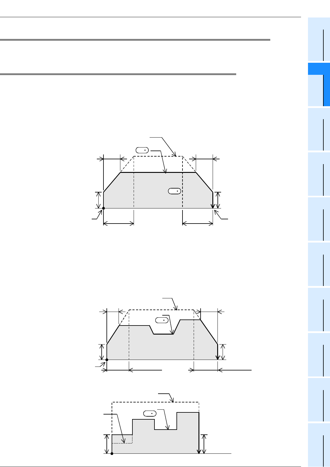
FX
3G
/FX
3U
/FX
3UC
PLC User's Manual - Positioning Control Edition
Built-in Positioning Functions
4 Before Programming
4.2 Setting of Various Items Regarding Speeds
B - 41
A
Common Items
B
Built-in
Positioning
Functions
Apx.
Example
Connection
4.2 Setting of Various Items Regarding Speeds
Specify the output pulse frequency using the operand of each instruction or the related device to determine
the output pulse frequency, zero return speed, or creep speed.
4.2.1 Setting of Various Items Regarding Instructions and Speeds
1. Interrupt Positioning (DVIT) instruction, drive to increment (DRVI) instruction, and drive to
absolute (DRVA) instruction
For these instructions, it is necessary to specify the maximum speed, bias speed, acceleration time, and
deceleration time using the related devices in addition to the output pulse frequency specified by the operand
of the instruction.
→ For operation of DVIT instruction, refer to Chapter 9.
→ For operation of DRVI or DRVA instruction, refer to Chapter 8.
→
For details on each setting item, refer to Subsection 4.2.2 , and Subsection 4.2.5 to Subsection 4.2.8
2. Variable speed Pulse Output (PLSV) instruction
For the variable speed pulse output (PLSV) instruction, it is necessary to specify the maximum speed, bias
speed, acceleration time, and deceleration time using the related devices in addition to the output pulse
frequency specified by the operand of the instruction. However, note that the acceleration time and the
deceleration time are only valid during acceleration/deceleration (M8338 = ON).
→ For operation of PLSV instruction, refer to Chapter 10.
→ For details on each setting item, refer to Subsection 4.2.2 , and Subsection 4.2.5 to Subsection
4.2.8.
1) When acceleration/deceleration is being performed (M8338 = ON)
2) When acceleration/deceleration is not performed (M8338 = OFF)
Actual
acceleration time
Bias speed
Acceleration
time
Initial value: 100 ms
Deceleration
time
Number of
output pulses
Maximum speed
Initial value: 100,000 Hz
Actual
deceleration time
Bias speed
Current
position
Target
position
Initial value: 100 ms
Initial value: 0 Hz
S
1
Output pulse frequency
S
2
Bias speed
Acceleration
time
Initial value: 100 ms
Output pulse
frequency
Maximum speed
Initial value: 100,000 Hz Actual
deceleration time
Bias speed
Initial value: 100 ms
Initial value: 0 Hz
S
Current
position
Deceleration
time
Actual
acceleration time
Bias speed
Output pulse
frequency
Bias speed
Initial value: 0 Hz
S
Maximum speed
Initial value: 100,000 Hz
If the frequency value is
less than the bias speed
value, the frequency will
not be output.
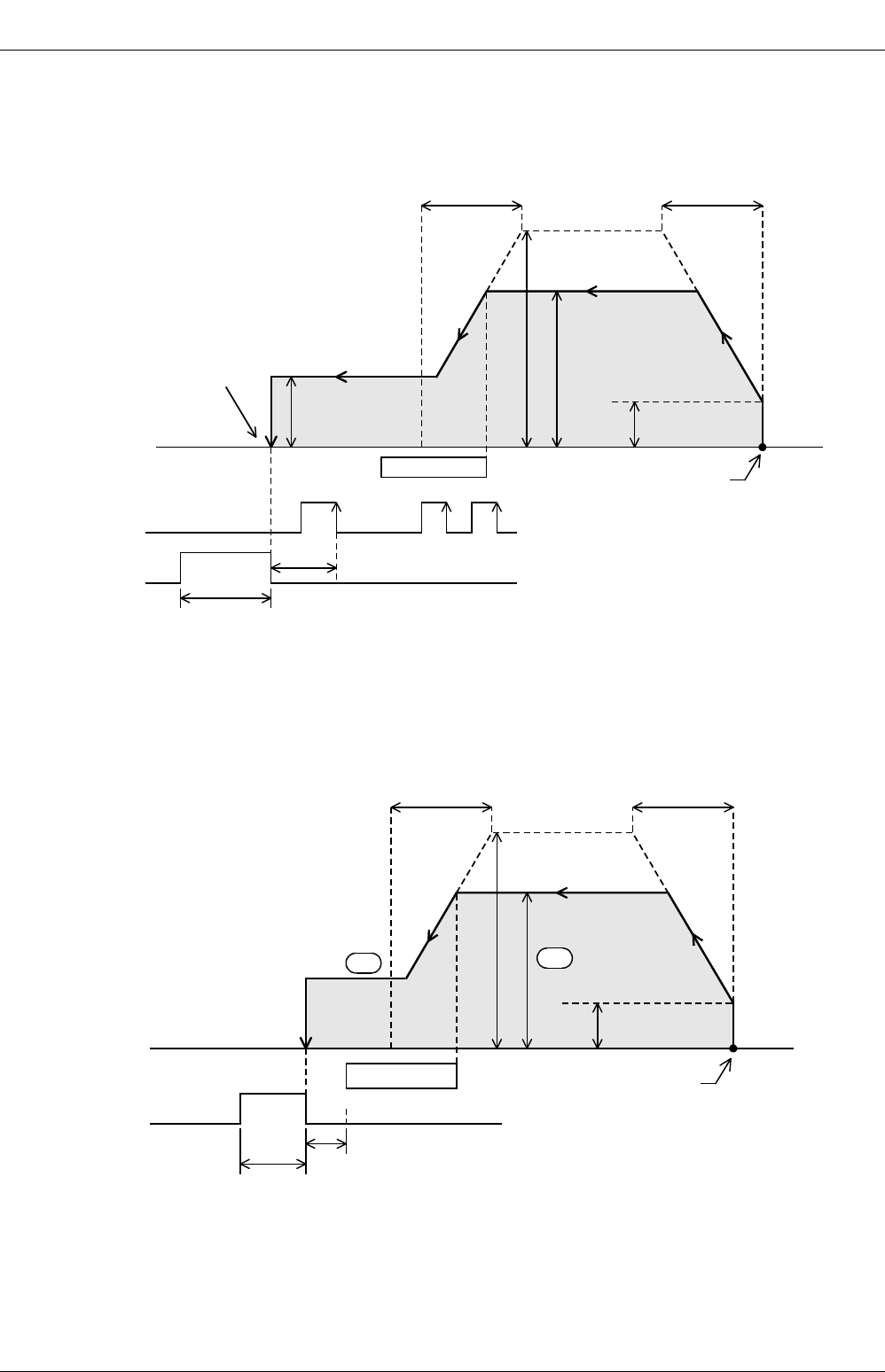
FX
3G
/FX
3U
/FX
3UC
PLC User's Manual - Positioning Control Edition
Built-in Positioning Functions
4 Before Programming
4.2 Setting of Various Items Regarding Speeds
B - 42
3. Zero return instruction with DOG search function (DSZR)
For this instruction, it is necessary to specify the maximum speed, bias speed, acceleration time, deceleration
time, zero return speed, and creep speed using the related devices.
→ For operation of DSZR instruction, refer to Section 6.2.
→ For details on each setting item, refer to Subsection 4.2.3 to Subsection 4.2.8.
4. Zero return (ZRN) instruction
For this instruction, it is necessary to specify the maximum speed, bias speed, acceleration time, and
deceleration time using the related devices in addition to the zero return speed and the creep speed specified
by the operand of the instruction.
→ For operation of ZRN instruction, refer to Section 6.1.
→ For details on each setting item, refer to Subsection 4.2.5 to Subsection 4.2.8.
Maximum speed
Initial value:
100,000 Hz
Zero return speed
Initial value: 50,000 Hz
Deceleration time
Bias speed
Initial value: 0 Hz
Acceleration time
DOG
Creep speed
Initial value:
1,000 Hz
CLEAR signal
Zero-phase signal
(X000 - X007)
Front endRear end
1 ms or less
20 ms + 1 scan time (ms)
Current value register = "0"
Initial value:
100 ms
Current position
Initial value:
100 ms
20 ms + 1 scan time (ms)
Zero return speed
Deceleration time Acceleration time
DOG
Creep speed
CLEAR signal Front endRear end
1 ms or less
S
2
•
S
1
•
Maximum speed
Initial value:
100,000 Hz
Initial value:
100 ms
Bias speed
Initial value: 0 Hz
Current position
Initial value:
100 ms
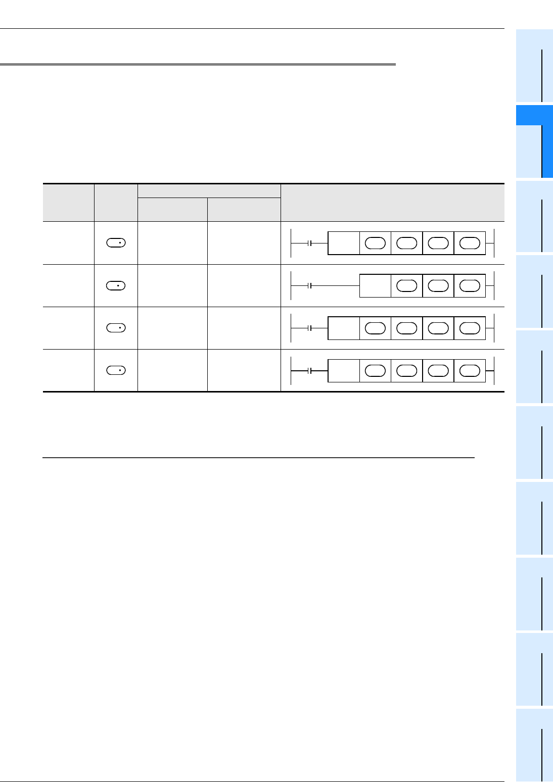
FX
3G
/FX
3U
/FX
3UC
PLC User's Manual - Positioning Control Edition
Built-in Positioning Functions
4 Before Programming
4.2 Setting of Various Items Regarding Speeds
B - 43
A
Common Items
B
Built-in
Positioning
Functions
Apx.
Example
Connection
4.2.2 Setting of Output Pulse Frequency (DVIT, PLSV, DRVI, and DRVA Instructions)
Set the output pulse frequency using the operand of each instruction. In this case, the setting range depends
on the instruction (see the following table).
However, even in the setting range of each instruction, if the set value of the output pulse frequency is more
than the maximum speed value, the operation will be performed at the maximum speed. If the set value of
the output pulse frequency is less than the bias speed value, the operation will be performed at the bias
speed.
→ For operation of DVIT instruction, refer to Chapter 9.
→ For operation of PLSV instruction, refer to Chapter 10.
→ For operation of DRVI or DRVA instruction, refer to Chapter 8.
*1. If FX3U-2HSY-ADP is not used, note that the frequency value cannot be more than 100,000 Hz.
*2. If FX3U-2HSY-ADP is not used, note that the frequency value cannot be less than -100,000 Hz.
*3. Only available for FX3U and FX3UC PLCs.
Caution:
• To use the main unit (transistor output), set the output pulse frequency (absolute value) to 100,000 Hz or less.
If more than 100,000 Hz is output from the transistor output of the main unit to perform operation, it may cause PLC
failure.
• Set the output pulse frequency so that the output pulse frequency value is less than the maximum frequency value
of the servo amplifier (driver unit).
Instruction Operand
Setting range
Instruction format
16-bit operation
(Hz)
32-bit operation
(Hz)
DVIT
instruction*3 10 to 32767 10 to 200,000*1
PLSV
instruction
-32768 to -1,
+1 to 32767
-200,000*2 to -1,
+1 to 200,000*1
DRVI
instruction 10 to 32767 10 to 200,000*1
DRVA
instruction 10 to 32767 10 to 200,000*1
S
2
DVIT S
1
•
S
2
•
D
1
•
D
2
•
S
PLSV S
•
D
1
•
D
2
•
S
2
DRVI S
1
•
S
2
•
D
1
•
D
2
•
S
2
DRVA S
1
•
S
2
•
D
1
•
D
2
•
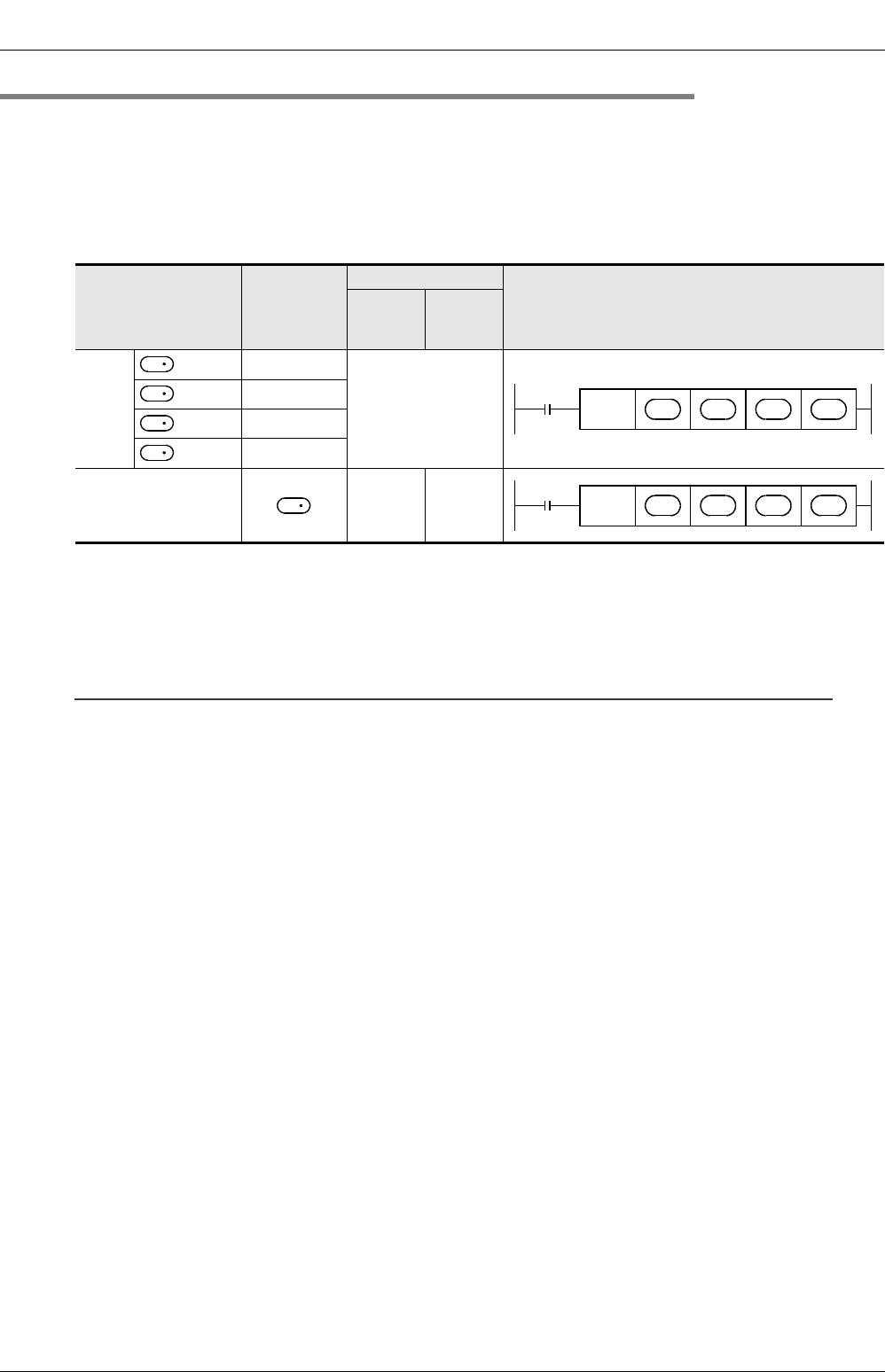
FX
3G
/FX
3U
/FX
3UC
PLC User's Manual - Positioning Control Edition
Built-in Positioning Functions
4 Before Programming
4.2 Setting of Various Items Regarding Speeds
B - 44
4.2.3 Setting of Zero Return Speed (DSZR/ZRN Instruction)
Use the related device or the operand of the instruction to set the zero return speed.
The zero return speed setting range is shown in the following table.
Be sure to set the zero return speed so that the relation with the other speeds can be "bias speed ≤ zero
return speed ≤ maximum speed". If the set value of the zero return speed is more than the maximum speed
value, operation will be performed at the maximum speed.
→ For operation of DSZR instruction, refer to Section 6.2.
→ For operation of ZRN instruction, refer to Section 6.3.
*1. If FX3U-2HSY-ADP is not used, note that this value cannot be more than 100,000 Hz.
*2. Y002 (pulse output destination) cannot be specified when the 14-point or 24-point type FX3G PLC is
connected.
*3. Devices related to Y003 (pulse output destination) are only valid if two FX3U-2HSY-ADP adapters are
connected to the FX3U PLC.
Caution:
• When using the transistor outputs of the main unit, set the pulse frequency for the zero return speed to less than
100 kHz.
If a pulse higher than 100 kHz is output from a transistor output of the main unit to perform an operation, PLC failure
may occur.
• Set the zero return speed so that the set value of the zero return speed is less than the maximum frequency value
of the servo amplifier (driver unit).
Instruction
Operand or
related
device
Setting range
Instruction format
16-bit
operation
(Hz)
32-bit
operation
(Hz)
DSZR
instru-
ction
=Y000 D8347,D8346
10 to 200,000*1
Initial value: 50000
=Y001 D8357,D8356
=Y002*2 D8367,D8366
=Y003*3 D8377,D8376
ZRN instruction 10 to
32767
10 to
200,000
*1
D
1
DSZR S
1
•
S
2
•
D
1
•
D
2
•
D
1
D
1
D
1
S
1
ZRN S
1
•
S
2
•
S
3
•
D
•
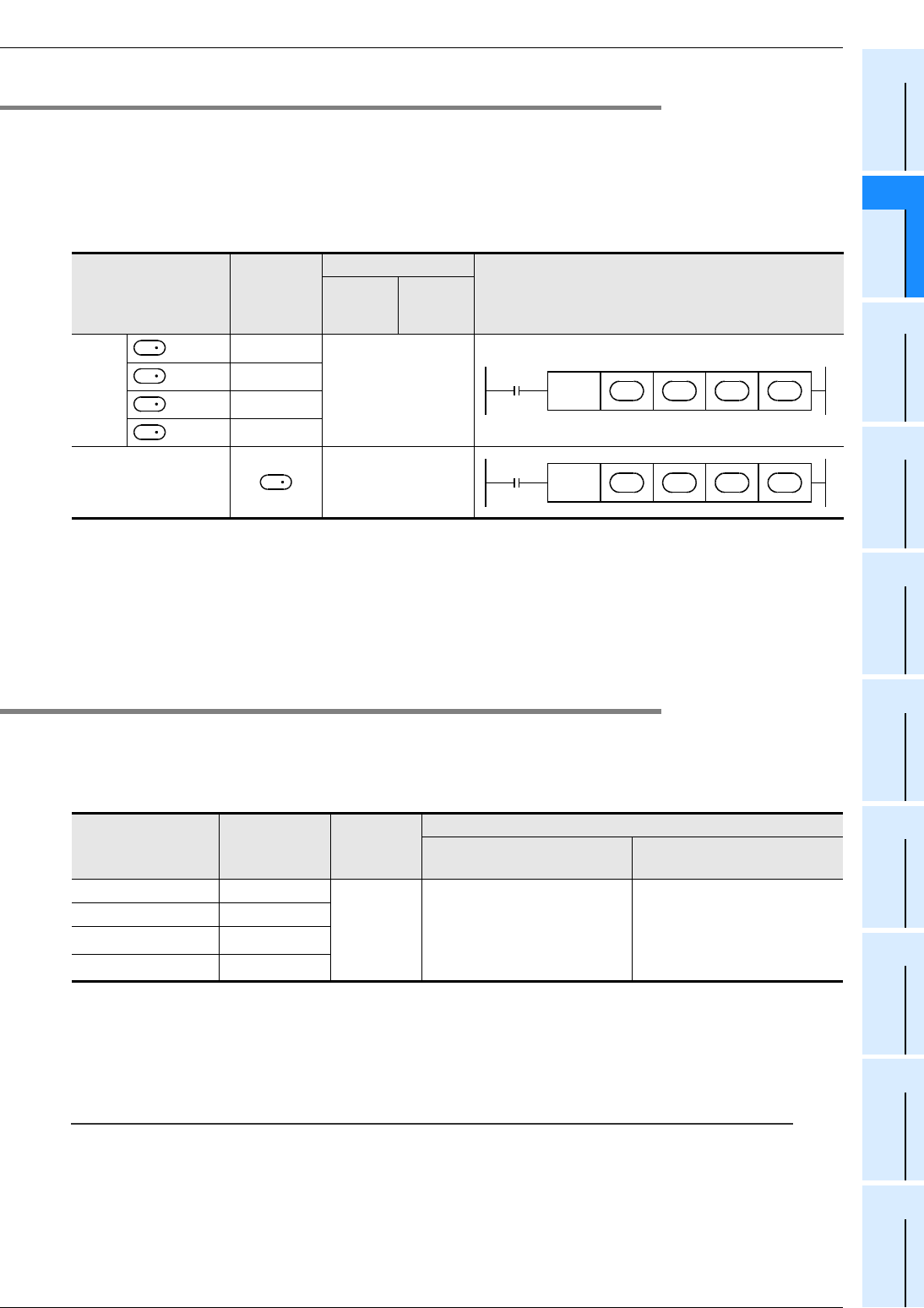
FX
3G
/FX
3U
/FX
3UC
PLC User's Manual - Positioning Control Edition
Built-in Positioning Functions
4 Before Programming
4.2 Setting of Various Items Regarding Speeds
B - 45
A
Common Items
B
Built-in
Positioning
Functions
Apx.
Example
Connection
4.2.4 Setting of Creep Speed (DSZR/ZRN Instruction)
Use the related device or the operand of the instruction to set the creep speed. The creep speed setting
range is shown in the following table.
Be sure to set the creep speed so that the relation with the other speeds is "bias speed ≤ creep speed ≤
32767 Hz*1".
→ For operation of DSZR instruction, refer to Section 6.2.
→ For operation of ZRN instruction, refer to Section 6.3.
*1. If the maximum speed is set to less than 32767 Hz, note that this value (32767 Hz) will automatically
be changed to the maximum speed.
*2. Y002 (pulse output destination) cannot be specified when the 14-point or 24-point type FX3G PLC is
connected.
*3. Devices related to Y003 (pulse output destination) are only valid if two FX3U-2HSY-ADP adapters are
connected to the FX3U PLC.
4.2.5 Setting of Maximum Speed
Set the maximum speed to determine the upper limit value for the output pulse frequency and the zero return
speed.
Use the devices shown in the following table to determine the maximum speed for each pulse output
destination device.
*1. Y002 (pulse output destination) cannot be specified when the 14-point or 24-point type FX3G PLC is
connected.
*2. Devices related to Y003 (pulse output destination) are only valid if two FX3U-2HSY-ADP adapters are
connected to the FX3U PLC.
Caution:
• To use the main unit (transistor output), set the output pulse frequency (absolute value) to 100,000 Hz or less.
If more than 100,000 Hz is output from the transistor output of the main unit to perform operation, it may cause PLC
failure.
• Set the output pulse frequency so that the output pulse frequency value is less than the maximum frequency value
of the servo amplifier (driver unit).
Instruction
Operand or
related
device
Setting range
Instruction format
16-bit
operation
(Hz)
32-bit
operation
(Hz)
DSZR
instru-
ction
=Y000 D8345
10 to 32767
Initial value: 1000
=Y001 D8355
=Y002*2 D8365
=Y003*3 D8375
ZRN instruction 10 to 32767
Pulse output
destination device
Maximum
speed Initial value
Setting range
Transistor output of main
unit
High-speed output special
adapter
Y000 D8344,D8343
100,000Hz
10 to 100,000 Hz:
If the value is set to 9 Hz or
less, the maximum speed will
be automatically set to 10 Hz.
10 to 200,000 Hz:
If the value is set to 9 Hz or
less, the maximum speed will
be automatically set to 10 Hz.
Y001 D8354,D8353
Y002*1 D8364,D8363
Y003*2 D8374,D8373
D
1
DSZR S
1
•
S
2
•
D
1
•
D
2
•
D
1
D
1
D
1
S
2
ZRN S
1
•
S
2
•
S
3
•
D
•

FX
3G
/FX
3U
/FX
3UC
PLC User's Manual - Positioning Control Edition
Built-in Positioning Functions
4 Before Programming
4.2 Setting of Various Items Regarding Speeds
B - 46
4.2.6 Setting of Bias Speed
To control the stepping motor using each instruction, set the bias speed considering the resonance range of
the stepping motor and the automatic start frequency.
Use the devices shown in the following table to determine the bias speed for each pulse output destination
device.
*1. Y002 (pulse output destination) cannot be specified when the 14-point or 24-point type FX3G PLC is
connected.
*2. Devices related to Y003 (pulse output destination) are only valid if two FX3U-2HSY-ADP adapters are
connected to the FX3U PLC.
4.2.7 Setting of Acceleration Time
Set the time required for acceleration from the bias speed to the maximum speed.
If the output pulse frequency is less than the maximum speed, the actual acceleration time will be shorter than
the set acceleration time.
If the variable speed pulse output (PLSV) instruction is used, the set acceleration time is only valid during
acceleration/deceleration (M8338 = ON)*3.
Use the devices shown in the following table to determine the acceleration time for each pulse output
destination device.
*1. Y002 (pulse output destination) cannot be specified when the 14-point or 24-point type FX3G PLC is
connected.
*2. Devices related to Y003 (pulse output destination) are only valid if two FX3U-2HSY-ADP adapters are
connected to the FX3U PLC.
*3. Only available for FX3U/FX3UC PLC Ver. 2.20 or later and FX3G PLC.
Pulse output
destination device Bias speed Initial value Setting range
Y000 D8342
0Hz
1/10 or less of maximum speed:
If the value is set to more than 1/10 of the maximum speed,
the bias speed will be automatically set to 1/10 of the
maximum speed.
Y001 D8352
Y002*1 D8362
Y003*2 D8372
Pulse output
destination device
Acceleration
Time Initial value Setting range
Y000 D8348
100ms
50 to 5,000 ms:
If the value is set to 49 ms or less, the acceleration time will
be automatically set to 50 ms. If the value is set to 5,001 ms
or more, the acceleration time will be automatically set to
5,000 ms.
Y001 D8358
Y002*1 D8368
Y003*2 D8378

FX
3G
/FX
3U
/FX
3UC
PLC User's Manual - Positioning Control Edition
Built-in Positioning Functions
4 Before Programming
4.2 Setting of Various Items Regarding Speeds
B - 47
A
Common Items
B
Built-in
Positioning
Functions
Apx.
Example
Connection
4.2.8 Setting of Deceleration Time
Set the time required for deceleration from the maximum speed to the bias speed.
If the output pulse frequency is less than the maximum speed, the actual deceleration time will be shorter
than the set deceleration time.
If the variable speed pulse output (PLSV) instruction is used, the set deceleration time is only valid during
acceleration/deceleration (M8338 = ON)*3.
Use the devices shown in the following table to determine the deceleration time for each pulse output
destination device.
*1. Y002 (pulse output destination) cannot be specified when the 14-point or 24-point type FX3G PLC is
connected.
*2. Devices related to Y003 (pulse output destination) are only valid if two FX3U-2HSY-ADP adapters are
connected to the FX3U PLC.
*3. Only available for FX3U/FX3UC PLC Ver. 2.20 or later and FX3G PLC.
Pulse output
destination device
Deceleration
Time Initial value Setting range
Y000 D8349
100ms
50 to 5,000 ms:
If the value is set to 49 ms or less, the deceleration time will
be automatically set to 50 ms. If the value is set to 5,001 ms
or more, the deceleration time will be automatically set to
5,000 ms.
Y001 D8359
Y002*1 D8369
Y003*2 D8379
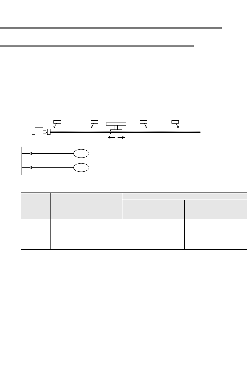
FX
3G
/FX
3U
/FX
3UC
PLC User's Manual - Positioning Control Edition
Built-in Positioning Functions
4 Before Programming
4.3 Various Special Relays for Operation Commands
B - 48
4.3 Various Special Relays for Operation Commands
4.3.1 Forward Rotation Limit and Reverse Rotation Limit
When using the servo motor, the forward rotation limit and the reverse rotation limit can be set for the servo
amplifier.
To use the DOG search function for zero return, or to set the forward rotation limit or the reverse rotation limit
for operations other than zero return using the PLC, set the forward rotation limit 1 (LSF) and reverse rotation
limit 1 (LSR) for the PLC so that these limit switches can be activated before the forward rotation limit 2 or
reverse rotation limit 2 of the servo amplifier.
As shown in the following figure, interlock the forward rotation limit 1 (LSF) with the forward limit relay, and the
reverse rotation limit 1 (LSR) with the reverse limit relay. If the forward limit relay or the reverse limit relay turns
ON, the motor will perform operation depending on the output instruction as shown in the following
table.
Use the relays shown in the following table to determine the forward rotation limit and the reverse rotation limit
for each pulse output destination device (Y000, Y001, Y002, Y003).
*1. Y002 (pulse output destination) cannot be specified when the 14-point or 24-point type FX3G PLC is
connected.
*2. Devices related to Y003 (pulse output destination) are only valid if two FX3U-2HSY-ADP adapters are
connected to the FX3U PLC.
*3. M8338 is supported in the FX3U/FX3UC PLC Ver. 2.20 or later and FX3G PLC. If an FX3UC PLC is used
and its version is below Ver.2.20, the PLSV instruction will perform operation in the M8338 = OFF
mode (will perform operation without acceleration/deceleration).
*4. Only available for FX3U and FX3UC PLCs.
Note:
If the forward rotation limit (LSF) and the reverse rotation limit (LSR) cannot be set, observe the following
items:
• Even if forward rotation limit 2 or reverse rotation limit 2 turns ON and the servo motor is automatically
stopped, the positioning instruction currently being activated cannot recognize the motor being stopped.
Therefore, pulses will be continuously output until the instruction is deactivated.
• The DOG search function of the DSZR instruction (zero return instruction with DOG search function)
cannot be used.
Pulse output
destination
device
Forward limit
relay
Reverse limit
relay
Corresponding instruction and stop
PLSV instruction
(M8338*3 =OFF)
DSZR, DVIT*4, ZRN,
PLSV(M8338*3 =ON), DRVI,
and DRVA instructions
Y000 M8343 M8344 If the corresponding rotation
limit relay is turned on,
the
pulse output (operation) will
immediately stop.
If the corresponding rotation
limit relay is turned on, the
speed will decelerate, and
the
operation will stop.
Y001 M8353 M8354
Y002*1 M8363 M8364
Y003*2 M8373 M8374
Reverse rotation limit 2
(Servo amplifier side)
Forward rotation limit 2
(Servo amplifier side)
Forward rotation limit 1
(Programmable
controller side)
LSF
Reverse rotation limit 1
(Programmable
controller side)
LSR
Reverse rotation Forward rotation
Servo motor
Forward rotation limit 1
M8343 Forward limit relay for Y000
Reverse rotation limit 1
M8344 Reverse limit relay for Y000
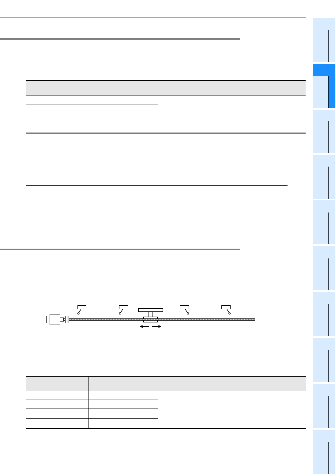
FX
3G
/FX
3U
/FX
3UC
PLC User's Manual - Positioning Control Edition
Built-in Positioning Functions
4 Before Programming
4.3 Various Special Relays for Operation Commands
B - 49
A
Common Items
B
Built-in
Positioning
Functions
Apx.
Example
Connection
4.3.2 Immediate Stop of Pulse Output (Pulse Output Stop Command Relay)
During the execution of a positioning instruction, if the pulse output stop command relay is turned on, the
pulses being output will immediately stop.
To output pulses again, turn off the pulse output stop command relay, deactivate (turn off) the positioning
instruction, and then activate the instruction again (turn it on again).
The following table shows the pulse output stop command relay of each pulse output destination device.
*1. Y002 (pulse output destination) cannot be specified when the 14-point or 24-point type FX3G PLC is
connected.
*2. Devices related to Y003 (pulse output destination) are only valid if two FX3U-2HSY-ADP adapters are
connected to the FX3U PLC.
Note:
Use these relays only if immediate stop is absolutely needed to avoid dangers. Since the motor is
immediately stopped, use of these relays may damage the system. For normal STOP operation (decelerate
to stop), use the "instruction OFF" function or "forward/reverse limit relay."
However, note that if the PLSV instruction is used together with the "instruction OFF" function or the "forward/
reverse limit relay" in the M8338 = OFF mode (operation without acceleration/deceleration), operation will
immediately stop.
4.3.3 Designation of Zero Return Direction (DSZR/ZRN Instruction)
Use the DSZR instruction (zero return instruction with DOG search function) or ZRN instruction (zero return
instruction) to specify the zero return direction*1. The zero return direction depends on the instruction.
→ For operation of DSZR instruction, refer to Section 6.2.
→ For operation of ZRN instruction, refer to Section 6.3.
*1. If the DSZR instruction (zero return instruction with DOG search function) is used, zero return will be
performed in the direction of the first operation.
1. Zero return instruction with DOG search function (DSZR instruction)
Turn on or off the zero return direction specification relay shown in the following table to specify the zero
return direction.
*1. Y002 (pulse output destination) cannot be specified when the 14-point or 24-point type FX3G PLC is
connected.
*2. Devices related to Y003 (pulse output destination) are only valid if two FX3U-2HSY-ADP adapters are
connected to the FX3U PLC.
Pulse output destination
device
Pulse output stop
command relay Operation
Y000 M8349 During pulse outputting operation, if the pulse output stop
command relay of the corresponding pulse output
destination device is turned on, the pulse outputting
operation will immediately stop.
Y001 M8359
Y002*1 M8369
Y003*2 M8379
Pulse output
destination device
Zero return direction
specification relay Description of setting
Y000 M8342 To perform zero return in the forward
rotation direction:Turn on the relay.
To perform zero return in the reverse
rotation direction:Turn off the relay.
Y001 M8352
Y002*1 M8362
Y003*2 M8372
Reverse rotation limit 2
(Servo amplifier side)
Reverse rotation limit 1
(Programmable
controller side)
LSR
Forward rotation limit 2
(Servo amplifier side)
Forward rotation limit 1
(Programmable
controller side)
LSF
Reverse rotation Forward rotation
Servo motor
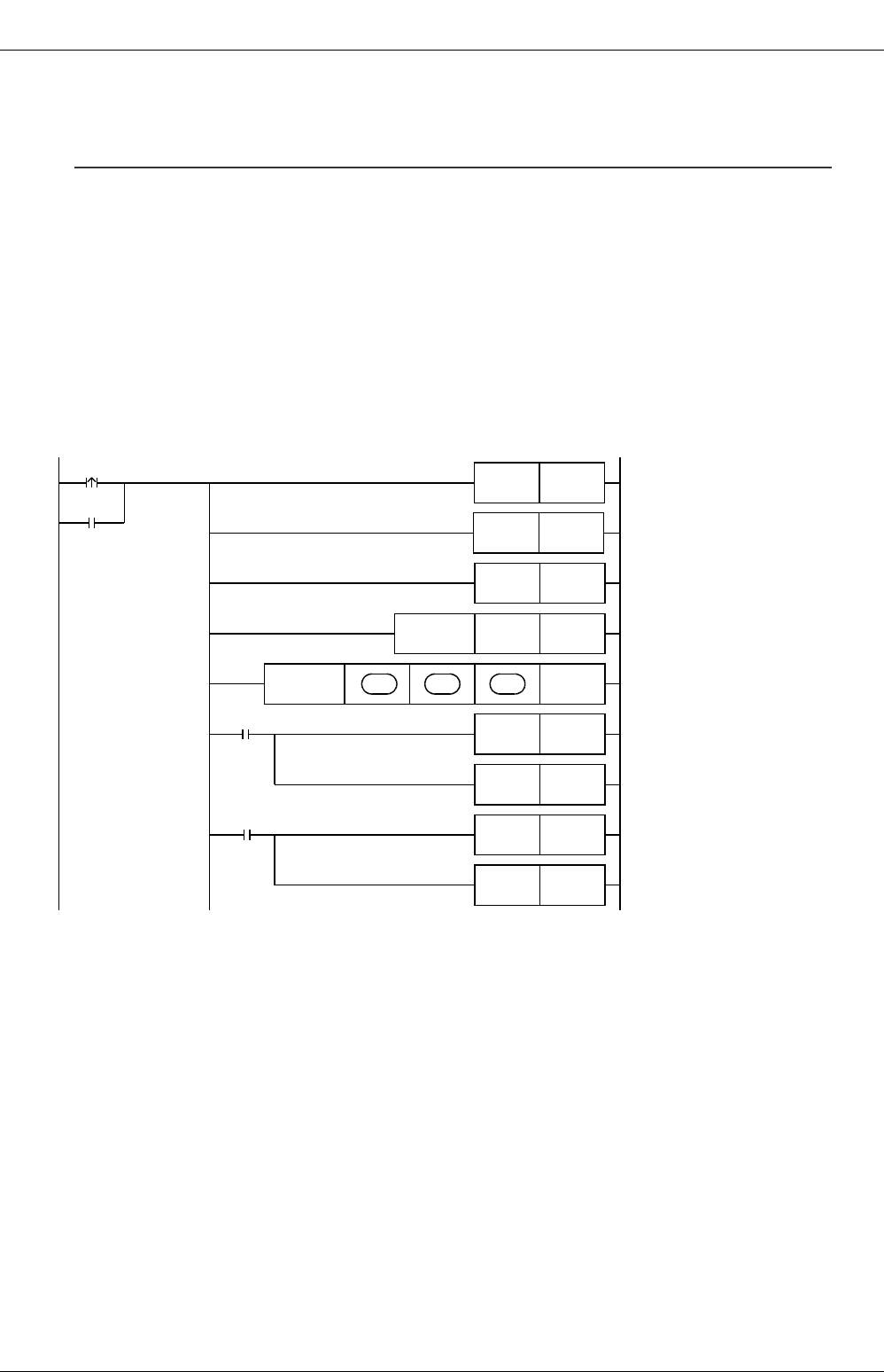
FX
3G
/FX
3U
/FX
3UC
PLC User's Manual - Positioning Control Edition
Built-in Positioning Functions
4 Before Programming
4.3 Various Special Relays for Operation Commands
B - 50
2. Zero return instruction (ZRN instruction)
Zero return will be performed in the reverse rotation direction only.
(During zero return, the value indicated by the current value register will be decreased.)
To perform zero return in the forward rotation direction using the ZRN instruction (zero return instruction):
To perform zero return in the forward rotation direction, create a program to control the output (Y) relay set as
a "rotational direction signal" as follows:
→ For details on programming, refer to Section 4.7.
→ To use
the
main unit (transistor output), refer to Section 4.8.
→ To use a high-speed output special adapter, refer to Section 4.9.
1) Turn on Y (rotational direction signal).
2) Refresh Y output using the REF (FNC50) instruction.
3) Execute the ZRN instruction (zero return instruction).
4) Using the execution completion flag (M8029) of the ZRN instruction (zero return instruction), reset
Y (rotational direction signal).
Example program:
The following program uses Y004 as the rotational direction signal for Y000.
C
omman
d
input
Turns on (sets) Y004 as the
rotational direction signal of Y000
(pulse output destination).
M8340
Y000 output
pulse monitor
K8Y000
Y000
Y004RST
Refreshes Y000 to Y007.
Executes ZRN instruction.
Resets the rotational direction
signal (Y004) using the instruction
execution complete flag.
Y004SET
FNC 50
REFP
FNC156
DZRN S
1
•
S
2
•
S
3
•
M8029
M11RST
M10RST
M10SET Origin data reading completion flag
Resets the rotational direction signal
(Y004) using the instruction
execution abnormal end flag.
Y004RST
M8329
M11SET Abnormal end of zero return
a)
b)
c)
d)
FX
3G
/FX
3U
/FX
3UC
PLC User's Manual - Positioning Control Edition
Built-in Positioning Functions
4 Before Programming
4.3 Various Special Relays for Operation Commands
B - 51
A
Common Items
B
Built-in
Positioning
Functions
Apx.
Example
Connection
4.3.4 CLEAR Signal Output (DSZR/ZRN Instruction)
The DSZR instruction (zero return instruction with DOG search function) and ZRN instruction (zero return
instruction) can stop the workpiece at the origin, and can output the CLEAR signal.
If it is necessary to output the CLEAR signal after zero return, turn on the "CLEAR signal output function
enable" relay. The following table shows the "CLEAR signal output function enable" relay of each pulse
output destination device (Y000, Y001, Y002, Y003).
Use an FX3U/FX3UC PLC Ver. 2.20 or later or FX3G PLC to specify the CLEAR signal output device.
→ For operation of DSZR instruction, refer to Section 6.2.
→ For operation of ZRN instruction, refer to Section 6.3.
1. If it is not necessary to use the CLEAR signal device specification function, or if an FX3UC PLC
below Ver. 2.20 is used:
*1. Y002 (pulse output destination) cannot be specified when the 14-point or 24-point type FX3G PLC is
connected.
*2. Devices related to Y003 (pulse output destination) are only valid if two FX3U-2HSY-ADP adapters are
connected to the FX3U PLC.
*3. Use an FX3U/FX3UC PLC Ver. 2.20 or later or FX3G PLC to use the "CLEAR signal device specification
function enable" relay.
2. If it is necessary to use the CLEAR signal device specification
function:
Turn on "CLEAR signal device specification function enable" relay to
specify the CLEAR signal output device (output Y) for the pulse output destination device using the CLEAR
signal device specification register.
*1. Y002 (pulse output destination) cannot be specified when the 14-point or 24-point type FX3G PLC is
connected.
*2. Devices related to Y003 (pulse output destination) are only valid if two FX3U-2HSY-ADP adapters are
connected to the FX3U PLC.
→ For the CLEAR signal device specification method, refer to the next page.
If it is necessary to use a high-speed output special adapter:
The output devices initially set for the CLEAR signal of the DSZR/ZRN instruction are the same output
devices as the "direction signal / reverse pulse train (rotation direction signals)" of the high-speed output
special adapters. Be sure to specify output numbers of other transistor outputs using the CLEAR signal
device specification function.
Pulse output
destination
device
Status of "CLEAR
signal output
function enable"
relay
Status of "CLEAR signal
device specification
function enable" relay*3
CLEAR signal device
number
Y000 M8341=ON M8464=OFF Y004
Y001 M8351=ON M8465=OFF Y005
Y002*1 M8361=ON M8466=OFF Y006
Y003*2 M8371=ON M8467=OFF Y007
Pulse output
destination
device
Status of "CLEAR
signal output function
enable" relay
Status of "CLEAR signal
device specification
function enable" relay
CLEAR signal device number
CLEAR signal device
specification register
Initial value (CLEAR
signal device)
Y000 M8341=ON M8464=ON D8464 -
Y001 M8351=ON M8465=ON D8465 -
Y002*1 M8361=ON M8466=ON D8466 -
Y003*2 M8371=ON M8467=ON D8467 -
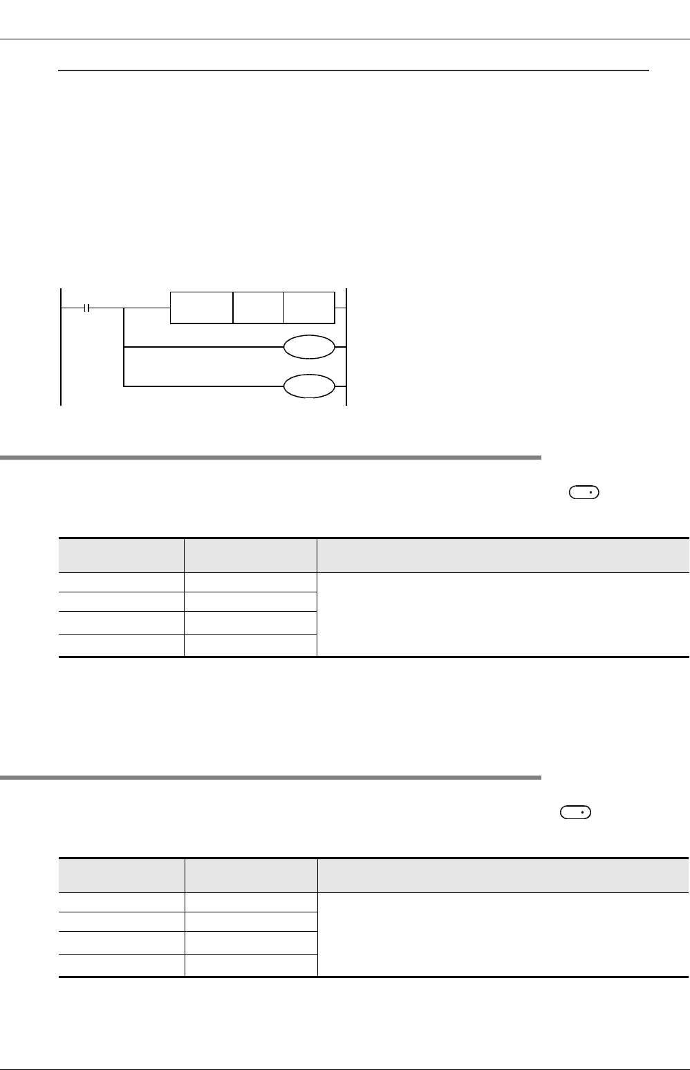
FX
3G
/FX
3U
/FX
3UC
PLC User's Manual - Positioning Control Edition
Built-in Positioning Functions
4 Before Programming
4.3 Various Special Relays for Operation Commands
B - 52
CLEAR signal device specification method:
1) Write the CLEAR signal output (Y) device number in the "CLEAR signal device specification" register with
a hexadecimal number (expressed in octal numbers).
e.g. setting H0010 means Y010. When setting H0008, an operation error occurs because Y008 does not
exist.
2) Turn on the "CLEAR signal output function enable" relay and "CLEAR signal device specification function
enable" relay to specify the CLEAR signal device.
3) Execute the DSZR instruction (zero return instruction with DOG search function) or ZRN instruction (zero
return instruction).
Example program:
The following figure shows a program that can specify Y010 as the CLEAR signal output device for Y000
(pulse output destination device):
4.3.5 Change in Logic of Near-Point (DOG) Signal (DSZR Instruction)
Turn on or off the "DOG signal logic reverse" relay to specify the logic of the near-point (DOG) signal of the
DSZR instruction (zero return instruction with DOG search function). Use the operand ( ) of the
instruction to specify the near-point (DOG) signal.
→ For operation of DSZR instruction, refer to Section 6.2.
*1. Y002 (pulse output destination) cannot be specified when the 14-point or 24-point type FX3G PLC is
connected.
*2. Devices related to Y003 (pulse output destination) are only valid if two FX3U-2HSY-ADP adapters are
connected to the FX3U PLC.
4.3.6 Change in Logic of Zero-Phase Signal (DSZR Instruction)
Turn on or off the "Zero point signal logic reverse" relay to specify the logic of the zero-phase signal of the
DSZR instruction (zero return instruction with dog search function). Use the operand ( ) of the
instruction to specify the zero-phase signal.
→ For operation of DSZR instruction, refer to Section 6.2.
*1. Y002 (pulse output destination) cannot be specified when the 14-point or 24-point type FX3G PLC is
connected.
*2. Devices related to Y003 (pulse output destination) are only valid if two FX3U-2HSY-ADP adapters are
connected to the FX3U PLC.
Pulse output
destination device
"DOG signal logic
reverse" relay Description of setting
Y000 M8345 OFF: Positive logic (Turning on the input will turn on the near-
point signal.)
ON: Negative logic (Turning off the input will turn on the near-
point signal.)
Y001 M8355
Y002*1 M8365
Y003*2 M8375
Pulse output
destination device
"Zero point signal
logic reverse" relay Description of setting
Y000 M8346 OFF: Positive logic (Turning on the input will turn on the zero-
phase signal.)
ON: Negative logic (Turning off the input will turn on the zero-
phase signal.)
Y001 M8356
Y002*1 M8366
Y003*2 M8376
M8000
RUN
monitor
Specifies the Y010 as the CLEAR signal output device for
Y000 (pulse output destination device).
Turns on "CLEAR signal device specification function enable"
relay for Y000 (pulse output destination device).
Turns on the "CLEAR signal output function enable" relay.
D8464H0010
FNC 12
MOVP
M8464
M8341
S
1
S
2
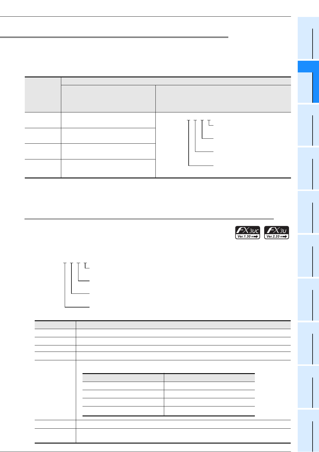
FX
3G
/FX
3U
/FX
3UC
PLC User's Manual - Positioning Control Edition
Built-in Positioning Functions
4 Before Programming
4.3 Various Special Relays for Operation Commands
B - 53
A
Common Items
B
Built-in
Positioning
Functions
Apx.
Example
Connection
4.3.7 Designation of Interrupt Input Signal for DVIT Instruction
The interrupt input signal of the interrupt positioning (DVIT) instruction depends on the pulse output
destination device as shown in the following table.
Use an FX3UC PLC Ver. 1.30 or later to use the interrupt input specification function.
Use an FX3U/FX3UC PLC Ver. 2.20 or later to set the user interrupt input command.
→ For operation of DVIT instruction, refer to Chapter 9.
*1. Devices related to Y003 (pulse output destination) are only valid if two FX3U-2HSY-ADP adapters are
connected to the FX3U PLC.
Designation of interrupt input using M8336 interrupt input
specification function:
1) Turn on M8336.
2) Set the interrupt input number (X000 to X007) in D8336, or
specify the user interrupt input command*1.
→ For specifying the settings, refer to the following description.
Pulse output
destination
device
Interrupt input signal
If it is not necessary to use the
interrupt input specification function
(M8336 = OFF), or if an FX3UC PLC
below Ver. 1.30 is used
If it is necessary to use the interrupt input specification
function (M8336 = ON)
Y000 X000
Y001 X001
Y002 X002
Y003*1 X003
Setting value Description of setting
0 Specifies X000 for the interrupt input signal.
1 Specifies X001 for the interrupt input signal.
~
~
7 Specifies X007 for the interrupt input signal.
8*1
Specifies the user interrupt input command*1 for the interrupt input signal.
9 to E*3 Do not specify these values.
FSet "F" for a pulse output destination device if the device is not used for the interrupt
positioning (DVIT) instruction.
D8336=H
{
{
{
{
Interrupt input for Y000
(pulse output destination device)
Interrupt input for Y001
(pulse output destination device)
Interrupt input for Y002
(pulse output destination device)
Interrupt input for Y003
(pulse output destination device)
D8336=H
{
{
{
{
Interrupt input for Y000
(pulse output destination device)
Interrupt input for Y001
(pulse output destination device)
Interrupt input for Y002
(pulse output destination device)
Interrupt input for Y003
(pulse output destination device)
Pulse output destination device User interrupt input command
Y000 M8460
Y001 M8461
Y002 M8462
Y003*2 M8463
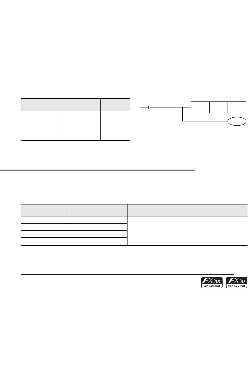
FX
3G
/FX
3U
/FX
3UC
PLC User's Manual - Positioning Control Edition
Built-in Positioning Functions
4 Before Programming
4.3 Various Special Relays for Operation Commands
B - 54
*1. A device can only be specified if an FX3U/FX3UC PLC Ver. 2.20 or later is used.
When using an FX3UC PLC below Ver. 2.20, if "8" is set and then the specified interrupt positioning
(DVIT) instruction turns ON, an operation error (error code: K6763) will occur, and the instruction will
not cause any operation.
*2. Devices related to Y003 (pulse output destination) are only valid if two FX3U-2HSY-ADP adapters are
connected to the FX3U PLC.
*3. After setting a number in the range of 9 to E for the interrupt input signal, if the corresponding interrupt
positioning (DVIT) instruction turns ON, an operation error (error code: K6763) will occur, and the
instruction will not cause any operation.
Example program:
The following program specifies the interrupt input signal for each pulse output destination device as shown in
the following table.
*1. Devices related to Y003 (pulse output destination) are only valid if two FX3U-2HSY-ADP adapters are
connected to the FX3U PLC.
4.3.8 Change in Logic of interrupt input Signal (DVIT Instruction)
Turn the "Interrupt signal logic reverse" relay ON or OFF to specify the logic of the interrupt input signal of the
interrupt positioning (DVIT) instruction.
→ For operation of DVIT instruction, refer to Chapter 9.
→ For details on the interrupt input signal designation method, refer to
Subsection 4.3.7.
*1. Devices related to Y003 (pulse output destination) are only valid if two FX3U-2HSY-ADP adapters are
connected to the FX3U PLC.
Caution:
If a user interrupt input command (M8460 to M8463) is specified in the interrupt input signal, the logic of the
user interrupt input command cannot be specified. This is because turning on the user interrupt input
command will turn on the interrupt input signal.
Pulse output
destination device
Interrupt input
signal Setting value
Y000 X003 3
Y001 M8461 8
Y002 Unused F
Y003*1 Unused F
Pulse output
destination device
"Interrupt signal logic
reverse" relay Description
Y000 M8347 OFF: Positive logic (Turning the input ON will turn on the
interrupt input signal.)
ON: Negative logic (Turning the input OFF will turn on the
interrupt input signal.)
Y001 M8357
Y002 M8367
Y003*1 M8377
RUN monitor
FNC 12
MOVP HFF83 D8336
M8000
M8336
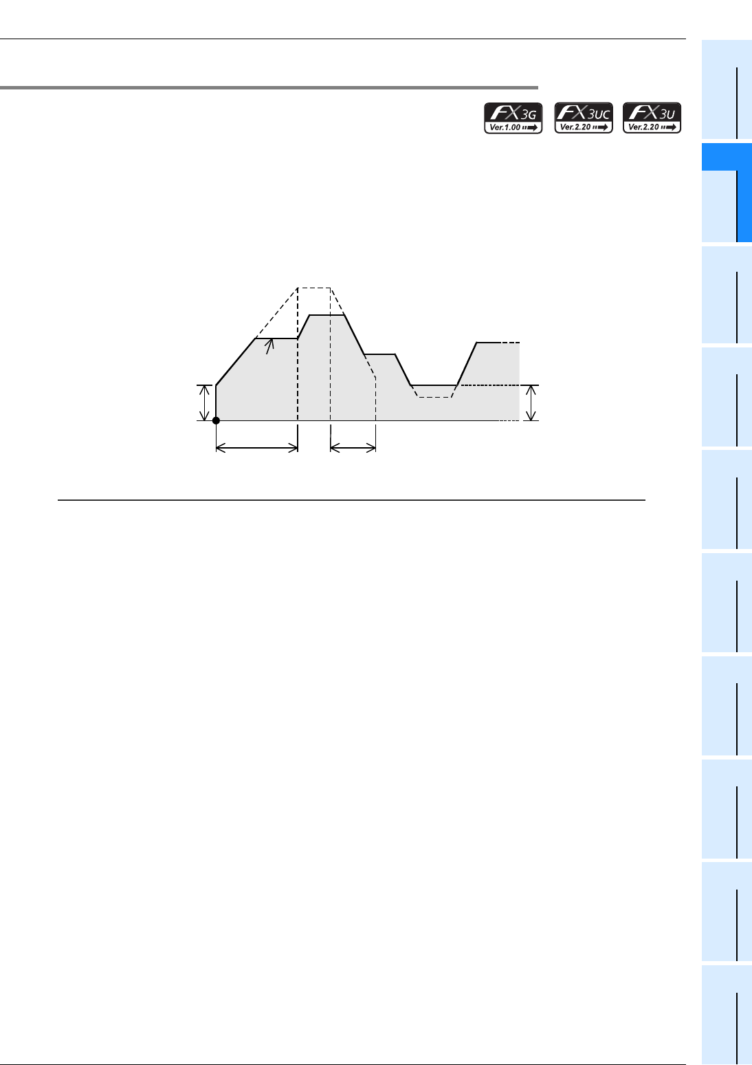
FX
3G
/FX
3U
/FX
3UC
PLC User's Manual - Positioning Control Edition
Built-in Positioning Functions
4 Before Programming
4.3 Various Special Relays for Operation Commands
B - 55
A
Common Items
B
Built-in
Positioning
Functions
Apx.
Example
Connection
4.3.9 Acceleration/Deceleration by PLSV Instruction
Using an FX3U/FX3UC PLC Ver. 2.20 or later or FX3G PLC, if M8338 (acceleration/deceleration operation) is
turned on, the variable speed pulse output (PLSV) instruction will be activated to accelerate/decelerate the
operation.
This means that if the command value of the output pulse frequency is changed, the operation will be
accelerated or decelerated to the changed output pulse frequency depending on the specified acceleration/
deceleration time.
→ For operation of PLSV instruction, refer to Chapter 10.
Caution:
• To enable acceleration/deceleration, turn on M8338 first, and then activate the variable speed pulse output
(PLSV) instruction.
• If acceleration/deceleration is enabled, the variable speed pulse output (PLSV) instructions of all the pulse
output destination devices will accelerate/decelerate with the same time. This means that acceleration/
deceleration cannot be specified separately for each pulse output destination device.
Bias speed
Acceleration
time
Initial value: 100 ms
Deceleration time
Output
pulse
frequency
Maximum speed
Initial value: 100,000 Hz
Initial value: 100 ms
Initial value: 0 Hz
Bias speed

FX
3G
/FX
3U
/FX
3UC
PLC User's Manual - Positioning Control Edition
Built-in Positioning Functions
4 Before Programming
4.4 Current Value and Flag for Monitoring of Operation
B - 56
4.4 Current Value and Flag for Monitoring of Operation
4.4.1 Current Value
During positioning operation, use the current value register to check the current value positioning address.
The current value will be increased or decreased depending on the rotation direction. The following table
shows the current value register (32-bit) of each pulse output destination device.
*1. Y002 (pulse output destination) cannot be specified when the 14-point or 24-point type FX3G PLC is
connected.
*2. Devices related to Y003 (pulse output destination) are only valid if two FX3U-2HSY-ADP adapters are
connected to the FX3U PLC.
Caution:
The current value changes between -2,147,483,648 and 2,147,483,647. However, if an overflow or
underflow occurs, the value changes as shown below. Check the value carefully.
• If the current value is increased past the maximum value, the minimum value will be indicated.
• If the current value is decreased below the minimum value, the maximum value will be indicated.
Necessity of zero return:
If the specified forward rotation pulse or reverse rotation pulse is output, the current value register will
increase or decrease the current value. Upon turning off the power of the PLC, however, the current value
stored in the current value register will be erased. For this reason, after turning the power on again, be sure
to adjust the current value of the current value register to the current position of the machine. For this
adjustment, use the zero return instruction or the Absolute Current Value Read instruction (absolute position
detection system) shown below:
→ For details on DSZR instruction, refer to Section 6.2.
→ For details on ZRN instruction, refer to Section 6.3.
→ For details on ABS instruction, refer to Chapter 7.
*3. The absolute position detection function applies for the MR-HA, MR-J2A MR-J2SA, or MR-
J3A servo amplifiers. If one of these servo amplifiers is used and mechanical zero return is
performed only once just before turning off the power, the current value will not be erased even after
power-off.
After turning on the power again, read out the stored current value using the ABS (FNC155)
instruction of the PLC. This means that the current value can be obtained without performing zero
return just after turning on the power again.
Pulse output destination device Current value register (32-bit)
Y000 D8341,D8340
Y001 D8351,D8350
Y002*1 D8361,D8360
Y003*2 D8371,D8370
Instruction Description
DSZR(FNC150) Zero return instruction with DOG search function
ZRN(FNC156) Zero return instruction (without DOG search function)
ABS(FNC155)*3 Absolute Current Value Read instruction

FX
3G
/FX
3U
/FX
3UC
PLC User's Manual - Positioning Control Edition
Built-in Positioning Functions
4 Before Programming
4.4 Current Value and Flag for Monitoring of Operation
B - 57
A
Common Items
B
Built-in
Positioning
Functions
Apx.
Example
Connection
4.4.2 Completion of Instruction Execution ("Instruction execution complete" Flag,
"Instruction execution abnormal end" Flag)
Use the "Instruction execution complete" flag or "Instruction execution abnormal end" flag to check whether
execution of the positioning instruction has been completed properly.
The "Instruction execution complete" flag and "Instruction execution abnormal end" flag are turned on or off
after each instruction. Use these flags just after the execution of each instruction.
→ For programming details, refer to Subsection 4.7.4.
• "Instruction execution complete" flag: Will be turned on if the instruction is executed properly.
• "Instruction execution abnormal end" flag: Will be turned on if the instruction is not executed properly.
Caution:
If the "Instruction execution complete" flag or "Instruction execution abnormal end" flag is turned on, then the
execution of the instruction (pulse outputting operation, etc.) is complete. However, it is not certain whether
the servo motor has stopped or not. Check the "positioning completion" signal of the servo amplifier (drive
unit) to determine whether the servo motor has stopped.
4.4.3 "Pulse Output Monitor" (BUSY/READY) Flag
Use the "pulse output monitor" (BUSY/READY) flag to check whether pulses are being output to the pulse
output destination device. The following table shows the "pulse output monitor" (BUSY/READY) flag of each
pulse output destination device.
*1. Y002 (pulse output destination) cannot be specified when the 14-point or 24-point type FX3G PLC is
connected.
*2. Devices related to Y003 (pulse output destination) are only valid if two FX3U-2HSY-ADP adapters are
connected to the FX3U PLC.
4.4.4 "Positioning Instruction Activation" Flag
Use the "positioning instruction activation" flag of each pulse output destination device to check whether or
not a positioning instruction is being executed for the pulse output destination device. Use this flag to prevent
simultaneous activation of two or more positioning instructions for the same pulse output destination device.
*1. Y002 (pulse output destination) cannot be specified when the 14-point or 24-point type FX3G PLC is
connected.
*2. Devices related to Y003 (pulse output destination) are only valid if two FX3U-2HSY-ADP adapters are
connected to the FX3U PLC.
Pulse output
destination device
"Pulse output monitor"
(BUSY/READY) flag Status of flag and pulse
Y000 M8340
Outputting pulse (BUSY):Flag = ON
Pulse outputting stopped (READY):Flag = OFF
Y001 M8350
Y002*1 M8360
Y003*2 M8370
Pulse output
destination device
"Positioning instruction
Activation" flag Status of flag and pulse
Y000 M8348 ON: The positioning instruction is being activated for the
corresponding pulse output destination.
(Even after instruction execution is completed, if the
instruction is still being activated, the flag will not be
turned off.)
OFF: The positioning instruction is not being activated for the
corresponding pulse output destination.
Y001 M8358
Y002*1 M8368
Y003*2 M8378

FX
3G
/FX
3U
/FX
3UC
PLC User's Manual - Positioning Control Edition
Built-in Positioning Functions
4 Before Programming
4.5 Setting of Various Items on PLC Side
B - 58
4.5 Setting of Various Items on PLC Side
4.5.1 Setting of Common Items Using Program
For each pulse output destination device (Y000, Y001, Y002*1, Y003*2), set the items shown in the following
table without using the operand of the instruction.
Setting
item
Setting device Instruction Refer to
Y000 Y001 Y002
*1
Y003
*2
DSZR ZRN ABS TBL PLSV DVIT DRVI DRVA
Items related to speed
Maximum
speed*3
D8344,
D8343
D8354,
D8353
D8364,
D8363
D8374,
D8373 33 -3*4 3333
Subsec-
tion
4.2.5
Bias speed D8342 D8352 D8362 D8372 33 -3*4 3333
Subsec-
tion
4.2.6
Acceleration
time D8348 D8358 D8368 D8378 33 -3*4 3*5 333
Subsec-
tion
4.2.7
Deceleration
time D8349 D8359 D8369 D8379 33 -3*4 3*5 333
Subsec-
tion
4.2.8
Zero return
speed*3
D8347,
D8346
D8357,
D8356
D8367,
D8366
D8377,
D8376 3-------
Subsec-
tion
4.2.3
Creep speed D8345 D8355 D8365 D8375 3-------
Subsec-
tion
4.2.4
Items needed for (DSZR) zero return instruction with DOG search function and (ZRN) zero return instruction)
Zero return
direction M8342 M8352 M8362 M8372 33
*6 ------
Subsec-
tion
4.3.3
CLEAR
signal output M8341 M8351 M8361 M8371 33 ------
Subsec-
tion
4.3.4
CLEAR
signal device
change*7
M8464
D8464
M8465
D8465
M8466
D8466
M8467
D8467 33 ------
Subsec-
tion
4.3.4
Logic of
near-point
signal
M8345 M8355 M8365 M8375 33 ------
Subsec-
tion
4.3.5
Logic of
zero-phase
signal
M8346 M8356 M8366 M8376 3-------
Subsec-
tion
4.3.6
Items needed for variable speed pulse output (PLSV) instruction
Acceleration/
deceleration
Operation*5
M8338 ----
3---
Subsec-
tion
4.3.9
Items needed for interrupt positioning (DVIT) instruction*10
Interrupt
input signal
device
change*8
M8336
D8336 ---
3
*4, *10 -3--
Subsec-
tion
4.3.7

FX
3G
/FX
3U
/FX
3UC
PLC User's Manual - Positioning Control Edition
Built-in Positioning Functions
4 Before Programming
4.5 Setting of Various Items on PLC Side
B - 59
A
Common Items
B
Built-in
Positioning
Functions
Apx.
Example
Connection
*1. Y002 (pulse output destination) cannot be specified when the 14-point or 24-point type FX3G PLC is
connected.
*2. Devices related to Y003 (pulse output destination) are only valid if two FX3U-2HSY-ADP adapters are
connected to the FX3U PLC.
*3. 32 bits are used for the maximum speed setting device and the zero return speed setting device.
*4. Set this item using the PC parameter settings (positioning) of GX Developer (Ver.8.23Z or later) with
an FX3U/FX3UC PLC Ver.2.20 or later or FX3G PLC. The settings data set by the parameter setting will
be stored in the corresponding device.
*5. To accelerate or decelerate the operation using the variable speed pulse output (PLSV) instruction
with an FX3U/FX3UC PLC Ver.2.20 or later or an FX3G PLC, it is necessary to set this item.
If the operation is not accelerated or decelerated, or if an FX3UC PLC below Ver.2.20 is used, the
PLSV instruction will not use this item even if it is set.
*6. The ZRN instruction will not use any zero return direction setting devices. Using the program, adjust
the rotation direction output to the zero return direction.
*7. This item can be set using an FX3U/FX3UC PLC Ver.2.20 or later or an FX3G PLC.
*8. This item can be set using an FX3U/FX3UC PLC Ver.1.30 or later.
The user interrupt input command, however, can only be set using an FX3U/FX3UC PLC Ver.2.20 or
later.
*9. Use this function only if immediate stop is absolutely needed to avoid danger.
*10. Only available for FX3U and FX3UC PLCs.
User
interrupt
input
command *8
M8460 M8461 M8462 M8463 ---
3
*4, *10 -3--
Subsec-
tion
4.3.7
Logic of
interrupt input
signal
M8347 M8357 M8367 M8377 ---
3-3--
Subsec-
tion
4.3.8
Forward limit, reverse limit, and immediate stop of pulse output
Forward limit M8343 M8353 M8363 M8373 33 -33333
Subsec-
tion
4.3.1
Reverse limit M8344 M8354 M8364 M8374 33 -33333
Subsec-
tion
4.3.1
Immediate
stop of pulse
output*9
M8349 M8359 M8369 M8379 33 -33333
Subsec-
tion
4.3.2
Setting
item
Setting device Instruction Refer to
Y000 Y001 Y002
*1
Y003
*2
DSZR ZRN ABS TBL PLSV DVIT DRVI DRVA

FX
3G
/FX
3U
/FX
3UC
PLC User's Manual - Positioning Control Edition
Built-in Positioning Functions
4 Before Programming
4.5 Setting of Various Items on PLC Side
B - 60
Example program:
In the following program, the zero return instruction with DOG search function (DSZR), variable speed pulse
output (PLSV) instruction, and interrupt positioning (DVIT) instruction are used for the pulse output
destination (Y000) under the conditions shown in the following table.
1) Set conditions
*1. Only available for FX3U and FX3UC PLCs.
Setting item Description of setting Related
device
Setting value
or condition
Items related to speed
Maximum speed 30000Hz
D8344,
D8343
(32-bit)
K30000
Bias speed 10Hz D8342 K10
Acceleration time 200ms D8348 K200
Deceleration time 200ms D8349 K200
Zero return speed 5000Hz
D8347,
D8346
(32-bit)
K5000
Creep speed 500Hz D8345 K500
Items needed for DSZR instruction (zero return instruction with DOG search function) and ZRN instruction (zero
return instruction)
Zero return direction Reverse rotation direction M8342 OFF
CLEAR signal output
Output to Y010
M8341 ON
CLEAR signal device change*6 M8464 ON
D8464 H0010
Logic of near-point signal Sets the positive logic (turning on the input will
turn on the near-point signal). M8345 OFF
Logic of zero-phase signal Sets the positive logic (turning on the input will
turn on the zero-phase signal). M8346 OFF
Items needed for variable speed pulse output (PLSV) instruction
Acceleration/deceleration Operation
If X012 is turned on, the variable speed pulse
output (PLSV) instruction will be activated to
accelerate or decelerate the operation.
M8338 ON:
If X012 = ON
Items needed for interrupt positioning (DVIT) instruction*1
Interrupt input signal device change
Sets X007 for interrupt inputs.
Interrupt positioning (DVIT) instruction will not
be used for the pulse output destinations
Y001, Y002, and Y003.
M8336 ON
D8336 HFFF7
User interrupt input command Do not use. M8460 -
Logic of interrupt input signal
Sets the negative logic (turning off the input
will turn on the interruption signal). M8347 ON
Forward limit, reverse limit, and immediate stop of pulse output
Forward limit If X010 is turned off (if the NC contact is
turned on), the limit switch will be activated. M8343 ON:
If X010 = OFF
Reverse limit If X011 is turned off (if the NC contact is
turned on), the limit switch will be activated. M8344 ON:
If X011 = OFF
Immediate stop of pulse output Do not use. M8349 -
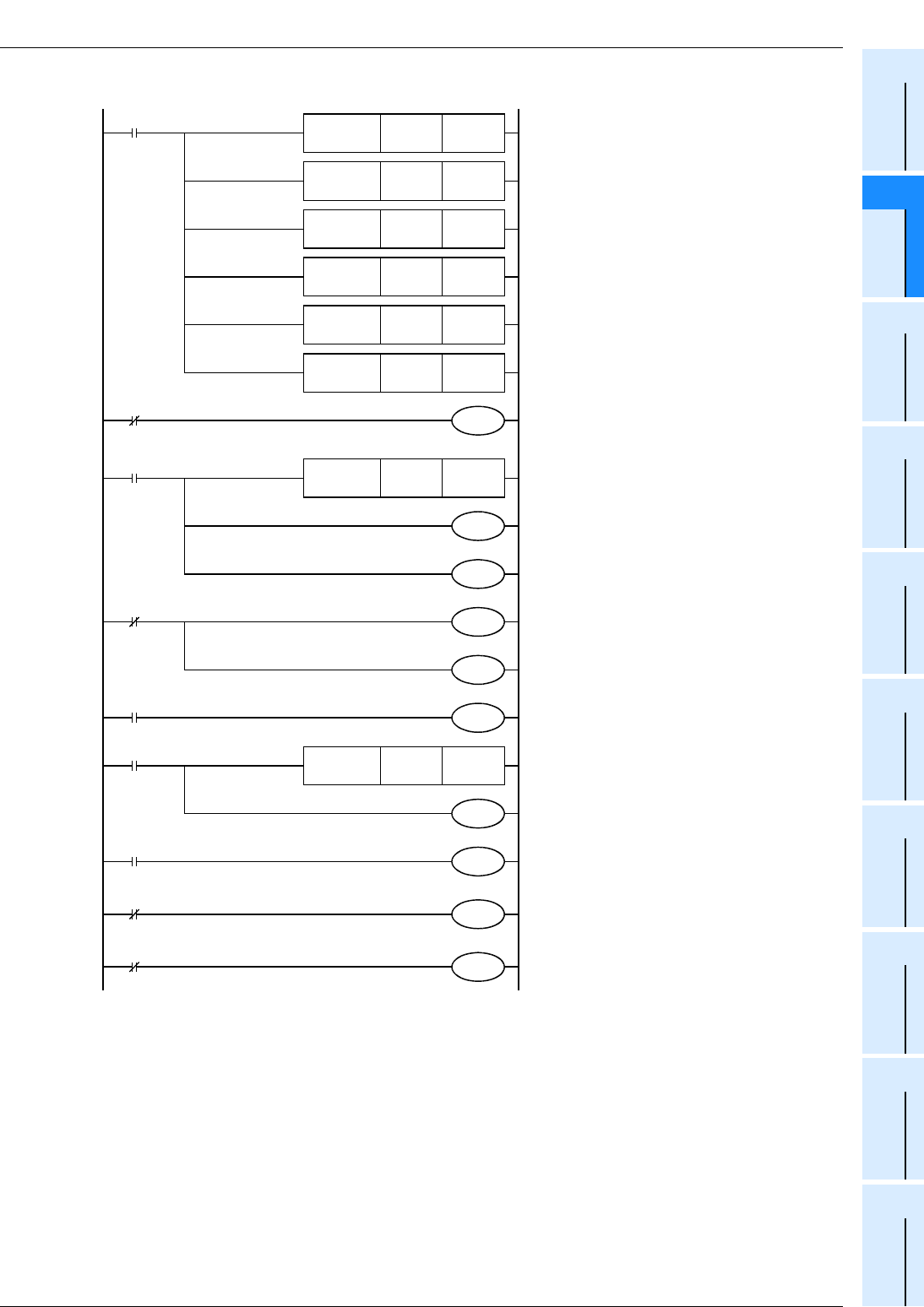
FX
3G
/FX
3U
/FX
3UC
PLC User's Manual - Positioning Control Edition
Built-in Positioning Functions
4 Before Programming
4.5 Setting of Various Items on PLC Side
B - 61
A
Common Items
B
Built-in
Positioning
Functions
Apx.
Example
Connection
2) Set program
Zero return direction (for Y000, DSZR instruction)
:Reverse rotation direction
M8342
M8000
RUN monitor
M8002 Maximum speed (for Y000):
30000 Hz
→
(D8344, D8343)
Initial pulse
Bias speed (for Y000):
10 Hz
→
D8342
Acceleration time (for Y000):
200 ms
→
D8348
Deceleration time (for Y000):
200 ms
→
D8349
Zero return speed (for Y000, DSZR instruction)
:5000 Hz
→
(D8347, D8346)
Creep speed (for Y000, DSZR instruction)
:500 Hz, D8345
D8343K30000
FNC 12
DMOV
D8342K10
FNC 12
MOV
D8348K200
D8349K200
D8346K5000
D8345K500
FNC 12
DMOV
FNC 12
MOV
FNC 12
MOV
FNC 12
MOV
M8000 CLEAR signal output (for Y000)
:Y010
RUN
monitor
D8464H0010
FNC 12
MOVP
Logic of near-point signal (for Y000)
:Positive logic
M8345
M8000
Logic for zero-phase signal
(for Y000, DSZR instruction)
:Positive logic
M8346
Acceleration/deceleration operation
(PLSV instruction)
:Enabled if X012 = ON
M8338
X012
M8000
Interruption input signal device
(for Y000, DVIT instruction)
:X007 (Y001 to Y003 will not be used.)
RUN
monitor
D8336HFFF7
FNC 12
MOVP
Logic of interruption input
signal:Negative logic
M8347
M8000
RUN monitor
Forward rotation limit (for Y000)M8343
X010
Reverse rotation limit (for Y000)M8344
X011
RUN
monitor
M8464
M8341
M8336
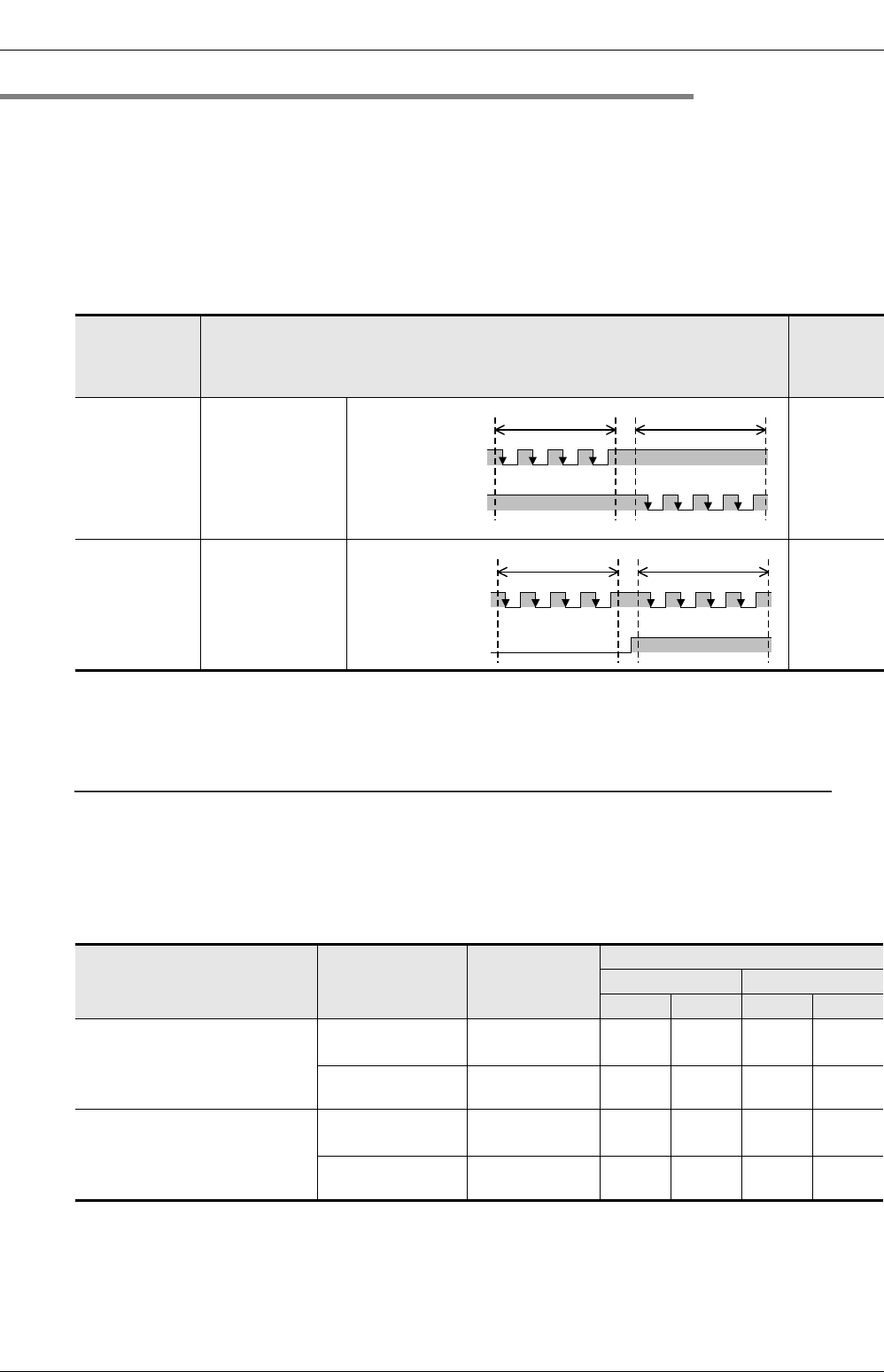
FX
3G
/FX
3U
/FX
3UC
PLC User's Manual - Positioning Control Edition
Built-in Positioning Functions
4 Before Programming
4.5 Setting of Various Items on PLC Side
B - 62
4.5.2 Setting of High-Speed Output Special Adapter
If a high-speed output special adapter (FX3U-2HSY-ADP) is used, the pulse output method can be selected
from "pulse train + direction" method and "forward/reverse rotation pulse train" method.
1. Setting of pulse output method
Using the pulse output method setting switch on the high-speed output special adapter (FX3U-2HSY-ADP),
set the pulse output method as shown in the following table.
The pulse output method setting should conform to the command pulse input method setting for the servo
amplifier (drive unit).
→ For details on the servo amplifier (drive unit), refer to the manual of the product used in your
system.
*1. "ON" and "OFF" represent the statuses of the PLC output. "H" and "L" respectively represent the
HIGH status and the LOW status of the waveform.
→ For details on the relation between the PLC output and the waveform, refer to
Subsection 4.6.1.
Caution:
Use the Output Form Setting Switch while the PLC is in STOP or while the power is OFF. Do not operate the
Output Form Setting Switch while a pulse train is being generated.
2. Setting of rotation direction signal for positioning instruction
If a high-speed output special adapter (FX3U-2HSY-ADP) is used, the rotation direction signal will be
assigned to each pulse output destination device as shown in the following table. Set the rotation direction
signal of the positioning instruction as shown in the following table:
Position of
pulse output
method setting
switch
Pulse output method
Logic of
command
pulse
FP•RP side
Forward rotation
pulse train (FP)
Reverse rotation
pulse train (RP)
Negative
logic
PLS•DIR side Pulse train +
direction
Negative
logic
Position of pulse output
method setting switch of high-
speed output special adapter
Signal
Name of
positioning
instruction
Output number
1st adapter 2nd adapter
1st axis 2nd axis 3rd axis 4th axis
FP•RP side
Forward rotation
pulse train (FP)
Pulse output
destination: Y000 Y001 Y002 Y003
Reverse rotation
pulse train (RP)
Rotation direction
signal Y004 Y005 Y006 Y007
PLS•DIR side
Pulse train Pulse output
destination: Y000 Y001 Y002 Y003
Direction Rotation direction
signal Y004 Y005 Y006 Y007
OFF
Forward rotation
pulse train (FP)
Reverse rotation
pulse train (RP)
Forward rotation Reverse rotation
*
1
OFF*
1
H
L
H
L
OFF
Pulse train
Direction
Forward rotation Reverse rotation
H
L
H
L
*
1
ON*
1
*
1

FX
3G
/FX
3U
/FX
3UC
PLC User's Manual - Positioning Control Edition
Built-in Positioning Functions
4 Before Programming
4.5 Setting of Various Items on PLC Side
B - 63
A
Common Items
B
Built-in
Positioning
Functions
Apx.
Example
Connection
3. CLEAR signal and rotation direction signal
If a high-speed output special adapter (FX3U-2HSY-ADP) is used, the same output will be used for both the
CLEAR signal and the rotation direction signal of the DSZR (FNC150) or ZRN (FNC156) instruction. For this
reason, it is necessary to change the CLEAR signal output device in order to output the CLEAR signal.
→ For details on the CLEAR signal device change method, refer to Subsection 4.3.4.
Pulse output
destination device
CLEAR signal device
initially set
Rotation direction signal
(reverse rotation pulse train / direction)
1st adapter 2nd adapter
1st axis 2nd axis 3rd axis 4th axis
Y000 Y004 Y004 - - -
Y001 Y005 - Y005 - -
Y002 Y006 - - Y006 -
Y003 Y007 - - - Y007
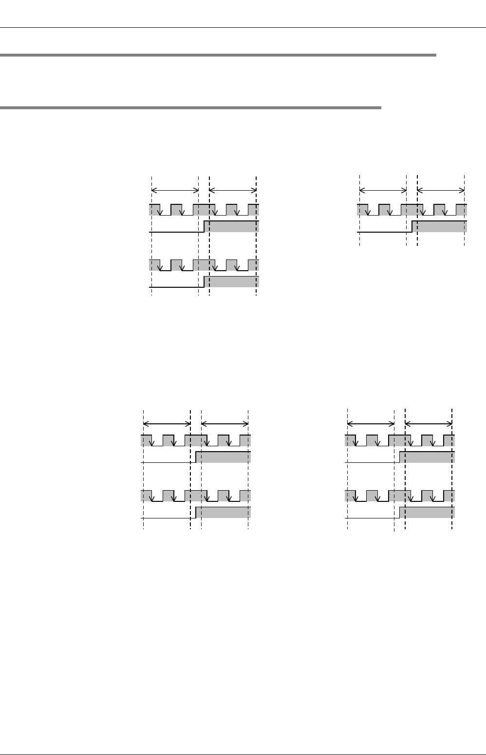
FX
3G
/FX
3U
/FX
3UC
PLC User's Manual - Positioning Control Edition
Built-in Positioning Functions
4 Before Programming
4.6 Setting of Various Items on Servo Amplifier (Drive Unit) Side
B - 64
4.6 Setting of Various Items on Servo Amplifier (Drive Unit) Side
→ For details on the servo amplifier (drive unit), refer to the manual of the product used in your
system.
4.6.1 Setting the Command Pulse Method
1. Pulse output method on PLC side
1) Main unit (transistor output (sink output))
If the main unit (transistor output (sink output)) is used, the pulse output signals (pulse output destination
and rotation direction) will be as shown in the following figure:
*1. "ON" and "OFF" represent the statuses of the PLC output. "H" and "L" respectively represent the
HIGH and LOW status of the waveform.
→ For details on the relation between the PLC output and the waveform, refer to the next pages.
2) High-speed output special adapter (Pulse train + Direction Setting)
When setting the Output Form Setting Switch of the high speed output special adapter to the "PLS•DIR"
position, the pulse output signals (pulse output destination signal and rotation direction signal) will be as
shown in the following figure:
*1. "ON" and "OFF" represent the statuses of the PLC output. "H" and "L" respectively represent the
HIGH status and the LOW status of the waveform.
→ For details on the relation between the high-speed output special adapter output and
the waveform, refer to the next pages.
Pulse output
destination: Y000
Any output: Y
(Rotation direction
designation)
Pulse output
destination: Y001
Any output: Y
(Rotation direction
designation)
Pulse output
destination: Y002
Any output: Y
(Rotation direction
designation)
Forward
rotation
Reverse
rotation
Forward
rotation
Reverse
rotation
ON*
1
H
L
H
L
ON*
1
H
L
H
L
OFF *
1
OFF *
1
H
L
H
L
ON *
1
OFF *
1
Rotation direction
designation: Y004
Pulse output
destination: Y001
Rotation direction
designation: Y005
Pulse output
destination: Y002
Rotation direction
designation: Y006
Pulse output
destination: Y003
Rotation direction
designation: Y007
Pulse output
destination: Y000
Forward
rotation
Reverse
rotation
Forward
rotation
Reverse
rotation
OFF *
1
OFF *
1
OFF *
1
OFF *
1
ON*
1
ON*
1
ON*
1
ON*
1
H
L
H
L
H
L
H
L
H
L
H
L
H
L
H
L
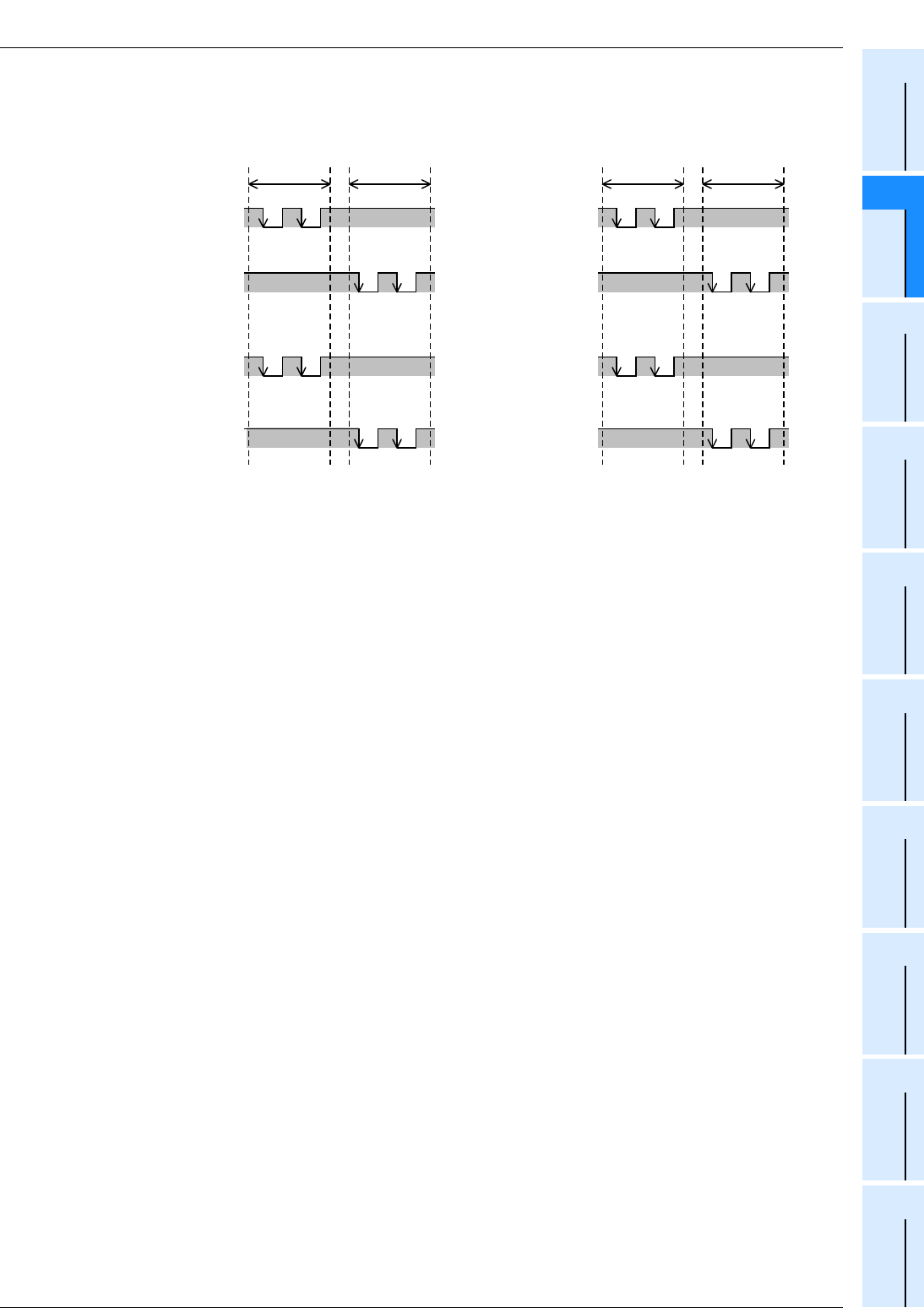
FX
3G
/FX
3U
/FX
3UC
PLC User's Manual - Positioning Control Edition
Built-in Positioning Functions
4 Before Programming
4.6 Setting of Various Items on Servo Amplifier (Drive Unit) Side
B - 65
A
Common Items
B
Built-in
Positioning
Functions
Apx.
Example
Connection
3) High-speed output special adapter (Forward/Reverse Pulse Train setting)
When setting the Output Form Setting Switch of the high speed output special adapter to the "FP•RP"
position, the pulse output signals will be as shown in the following figure.
*1. "ON" and "OFF" represent the statuses of the PLC output. "H" and "L" respectively represent the
HIGH status and the LOW status of the waveform.
→ For details on the relation between high-speed output special adapter output and the waveform,
refer to the next pages.
H
L
H
L
H
L
H
L
OFF *
1
OFF *
1
OFF *
1
OFF *
1
Forward
rotation
Reverse
rotation
Forward
rotation
Reverse
rotation
OFF *
1
H
L
H
L
H
L
H
L
OFF *
1
OFF *
1
OFF *
1
Pulse output
destination: Y002
(Forward rotation
pulse train)
Pulse output
destination: Y006
(Reverse rotation
pulse train)
Pulse output
destination: Y003
(Forward rotation
pulse train)
Pulse output
destination: Y007
(Reverse rotation
pulse train)
Pulse output
destination: Y001
(Forward rotation
pulse train)
Pulse output
destination: Y005
(Reverse rotation
pulse train)
Pulse output
destination: Y000
(Forward rotation
pulse train)
Pulse output
destination: Y004
(Reverse rotation
pulse train)
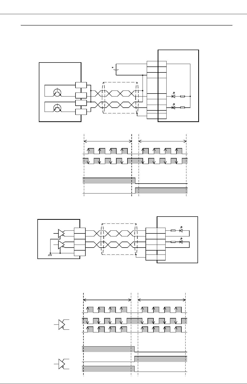
FX
3G
/FX
3U
/FX
3UC
PLC User's Manual - Positioning Control Edition
Built-in Positioning Functions
4 Before Programming
4.6 Setting of Various Items on Servo Amplifier (Drive Unit) Side
B - 66
Reference: Image of PLC output and waveform (for MELSERVO-J3 Series servo amplifier)
1) Base unit (transistor output (sink output))
a) Connection of PLC to servo amplifier
When a FX3U Series PLC (sink output) is used, it is connected as shown below.
b) Image of PLC output and output waveform
2) High-speed output special adapter (set to "pulse train + direction")
a) Connection of PLC to servo amplifier
b) Image of PLC output and output waveform
The output waveform shown below is based on the SGA terminal of the high-speed output special
adapter. If the SGB side of the high-speed output special adapter is used, the output waveform will be
that of the SGB terminal.
PP 10
DOCOM
46
OPC 12
NP 35
24V DC
Pulse train
Direction
SD
Plate
COM1
Y000
Y004
MR-J3
A servo
amplifier
FX
3U
-32MT/ES
(Transistor output
(sink output))
COM2
Pulse train signal
(Y000)
Direction output
(Y004)
Image of output
ON/OFF operation
Output waveform
Image of output
ON/OFF operation
Output waveform
ON
OFF
High
Low
Forward rotation Reverse rotation
ON
OFF
High
Low
Y0/2+
FX
3U
-2HSY-ADP
Y0/2-
SGA
Y4/6+
Y4/6-
Equivalent
to AM26C31
SGA
Pulse train
Direction
SD
Plate
MR-J3
A servo
amplifier
NP 35
PP 10
PG 11
NG 36
Pulse train signal
(Y000)
Direction output
(Y004)
Image of output
ON/OFF operation
Output
waveform
Forward rotation Reverse rotation
ON
OFF
High
Low
High
Low
ON
OFF
High
Low
High
Low
Image of output
ON/OFF operation
Output
waveform
+
-
+
-
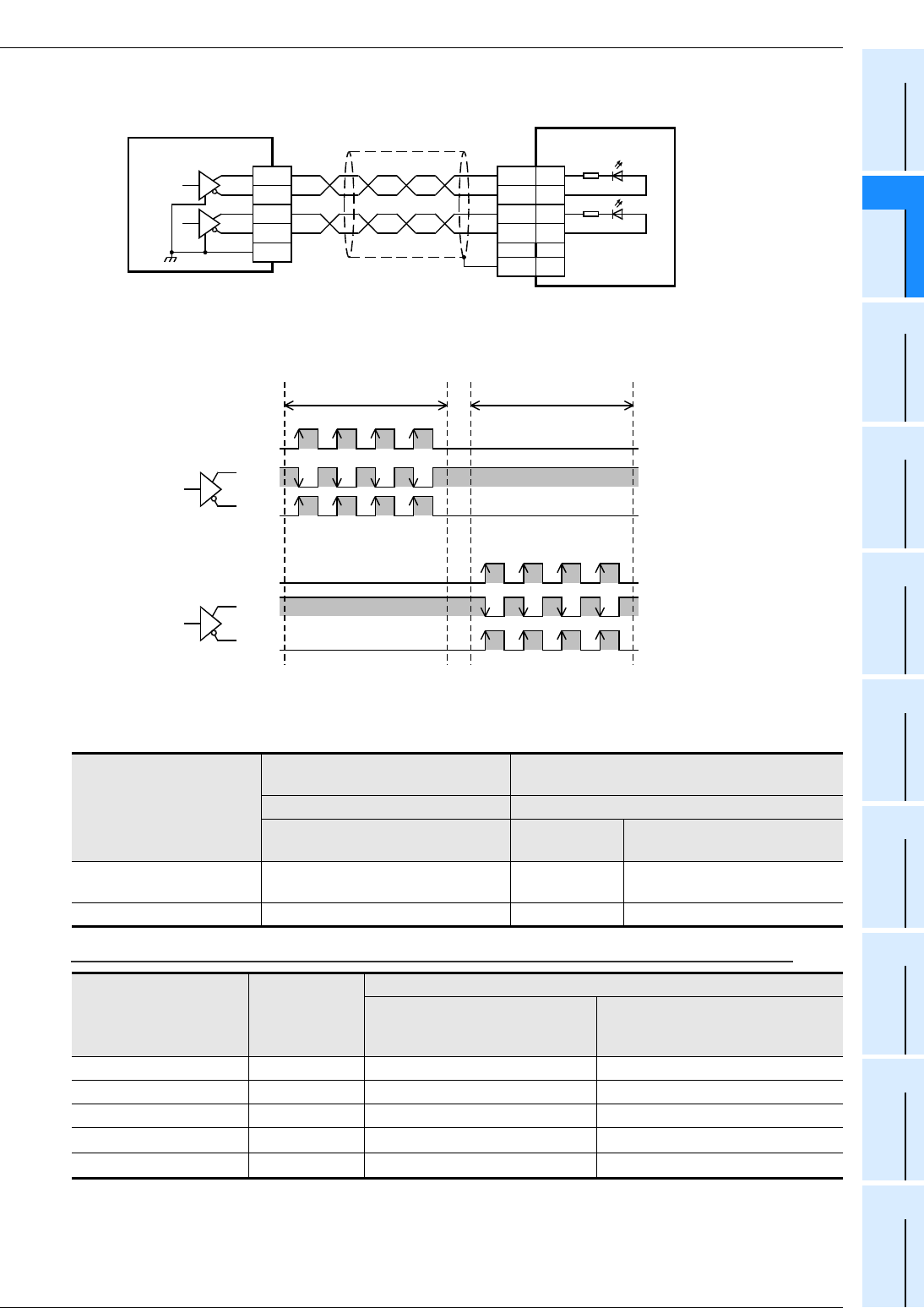
FX
3G
/FX
3U
/FX
3UC
PLC User's Manual - Positioning Control Edition
Built-in Positioning Functions
4 Before Programming
4.6 Setting of Various Items on Servo Amplifier (Drive Unit) Side
B - 67
A
Common Items
B
Built-in
Positioning
Functions
Apx.
Example
Connection
3) High-speed output special adapter (set to "forward/reverse rotation pulse train")
a) Connection of PLC to servo amplifier
b) Image of PLC output and output waveform
The output waveform shown below is based on the SGA terminal of the high-speed output special
adapter. If the SGB side of the high-speed output special adapter is used, the output waveform will be
that of the SGB terminal.
2. Setting of command pulse input method for servo amplifier (drive unit)
Set the following servo amplifier (drive unit) parameter so that the pulse train input method of the servo
amplifier (drive unit) matches the pulse output method of the PLC as shown in the following tables.
Parameter setting for each series of MELSERVO servo amplifier:
*1. is for settings other than the command pulse output form.
→ For details, refer to the Servo amplifier manual.
Servo amplifier
(drive unit)
Pulse output method of main unit Pulse output method of high-speed output
special adapter
Transistor output (sink output) Differential line driver
Pulse train + direction Pulse train +
direction
Forward rotation pulse train,
reverse rotation pulse train
Command pulse input
method "Pulse train + sign" "Pulse train +
sign"
Forward rotation pulse train,
Reverse rotation pulse train
Logic of command pulse "Negative logic" "Negative logic" "Negative logic"
Series Parameter No.
Set value
Pulse train + direction
Negative logic
forward/reverse rotation pulse
train
Negative logic
MR-J3 13 0011 0010
MR-J2,MR-J2S 21 0011 0010
MR-C 7 011 010
MR-H 21 011*1 010*1
MR-J 7 1*1 0*1
Y0/2+
FX
3U
-2HSY-ADP
Y0/2-
SGA
Y4/6+
Y4/6-
Equivalent
to AM26C31
SGA
Forward rotation
pulse train
Reverse rotation
pulse train
SD
Plate
MR-J3
A servo
amplifier
NP 35
PP 10
PG 11
NG 36
Forward rotation pulse
train(Y000)
Forward rotation Reverse rotation
Reverse rotation pulse
train(Y004)
Image of output
ON/OFF operation
Output
waveform
ON
OFF
High
Low
High
Low
ON
OFF
High
Low
High
Low
Image of output
ON/OFF operation
Output
waveform
+
-
+
-
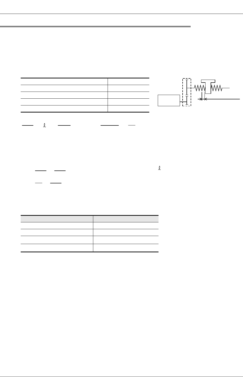
FX
3G
/FX
3U
/FX
3UC
PLC User's Manual - Positioning Control Edition
Built-in Positioning Functions
4 Before Programming
4.6 Setting of Various Items on Servo Amplifier (Drive Unit) Side
B - 68
4.6.2 Setting of Electronic Gear (For MELSERVO Series)
Use the electronic gear of the servo motor to set the transfer distance per pulse.
For details on the electronic gear setting, refer to the manual of the servo motor or servo amplifier, and set an
optimum value depending on the application.
Setting example 1:
To set the transfer distance per pulse to 10 µm (if the machine uses a ball screw):
Machine specifications
Set the electronic gear as follows:
CMX = 8, CDV = 1
In this case, when the main unit outputs the maximum output
pulse frequency (100 kHz), the servo motor rotational speed
will be as follows:
It is necessary to reduce the pulse frequency on the PLC side in order to reduce the servo motor rotational
speed so that it is less than the rated rotational speed.
*1. Y002 (pulse output destination) cannot be specified when the 14-point or 24-point type FX3G PLC is
connected.
*2. Devices related to Y003 (pulse output destination) are only valid if two FX3U-2HSY-ADP adapters are
connected to the FX3U PLC.
Servo amplifier MR-C Series
Rated rotational speed of servo motor 3000r/min
Lead of ball screw (Pb) 10mm (0.4")/rev
Reduction ratio (mechanical gear) (n) 1/2
Resolution of servo motor (Pt) 4000PLS/REV
Pulse output destination device Maximum speed setting device
Y000 D8344,D8343
Y001 D8354,D8353
Y002*1 D8364,D8363
Y003*2 D8374,D8373
f0 : Command pulse frequency [Hz]
(Open collector system)
CMX : Electronic gear
(numerator of command pulse
multiplying factor)
CDV : Electronic gear
(denominator of command pulse
multiplying factor)
N0 : Servo motor rotational speed [r/min]
0 : Transfer distance per pulse [mm]
Servo motor
Pt = 4000 (PLS/REV)
n
Pb=10[mm](0.4")
n=NL/NM=1/2
NL
NM
=
0
×
n
×
P
b
Pt
1/2
×
10
4000CMX
CDV = 10
×
10
-3
×
=1
8
×
CMX
CDV
N
0
= 60
Pt
×
f
0
=1
8
×
60
4000
×
100000
= 12000r/min > 3000r/min (Rated rotational speed of servo motor)

FX
3G
/FX
3U
/FX
3UC
PLC User's Manual - Positioning Control Edition
Built-in Positioning Functions
4 Before Programming
4.6 Setting of Various Items on Servo Amplifier (Drive Unit) Side
B - 69
A
Common Items
B
Built-in
Positioning
Functions
Apx.
Example
Connection
Setting example 2:
To set the transfer distance per pulse to 0.01° (if a turntable is used):
Machine specifications
Set the electronic gear as follows:
CMX = 32768, CDV = 1125
In this case, when the main unit outputs the maximum output
pulse frequency (100 kHz), the servo motor rotational speed will
be as follows:
It is not necessary to restrict the maximum speed on the PLC side because the servo motor rotational speed
is less than the rated rotational speed.
4.6.3 Setting of "Servo Ready" Signal (MELSERVO MR-C Series)
If the following parameter is set as shown in the following table for the MELSERVO MR-C Series, pin 3 of the
CN1 connector of the servo amplifier will be changed to "servo ready" (RD). Note that the following parameter
should be set for the example programs shown in Chapter 12.
Servo amplifier MR-J2S Series
Rated rotational speed of servo motor 3000r/min
Turntable 360°/REV
Reduction ratio (mechanical gear) (n)
(Timing belt) 8/64
Resolution of servo motor (Pt) 131072PLS/REV
Series Parameter No. Setting value
MR-C 21 020
Turntable
Timing belt: 8/64
Servo motor
Pt = 131072 (PLS/REV)
f0 : Command pulse frequency [Hz]
(open collector system)
CMX : Electronic gear
(numerator of command pulse
multiplying factor)
CDV : Electronic gear
(denominator of command pulse
multiplying factor)
N0 : Servo motor rotational speed [r/min]
0 : Transfer distance per pulse [° ]
=
0
×
n
×
360
Pt
8/64
×
360
131072CMX
CDV = 1
×
10
-2
×
=1125
32768
×
CMX
CDV
N
0
= 60
Pt
×
f
0
=
××
100000
1333.33
r/min < 3000r/min (Rated rotational speed)
1125
32768
131072
60
.
.
FX
3G
/FX
3U
/FX
3UC
PLC User's Manual - Positioning Control Edition
Built-in Positioning Functions
4 Before Programming
4.7 Items To Be Observed in Programming
B - 70
4.7 Items To Be Observed in Programming
This section describes various programming items that will not be affected by any pulse output destination
devices (hardware).
For information on the pulse output destination devices (hardware) that are affected by programming items,
refer to the following sections.
→ To use the transistor output of the main unit, also refer to Section 4.8.
→ To use the high-speed output special adapter, also refer to Section 4.9.
4.7.1 Positioning Instruction Activation Timing
The following positioning instructions can be programmed as many times as needed. However, observe the
items shown in the following table to determine the instruction activation timing.
3: If the pulse output destination device is now outputting pulses, the instruction cannot be activated. Refer
to the "Note" below.
: For the absolute position detection system, activate the ABS (FNC155) instruction after turning the
power ON for the servo amplifier. After executing this instruction, the current value will be read out from
the servo amplifier*1 only once.
Turning this instruction OFF will turn the servo amplifier OFF*1.
*1. The ABS (FNC155) instruction can be used with the absolute position detection system of the
MELSERVO-J3, -J2(S), and -H Series.
*2. Only available for FX3U and FX3UC PLCs.
Caution:
If the "pulse output monitor" (BUSY/READY) flag is on, and if a positioning instruction (excluding the ABS
instruction) or pulse output instruction (PLSR, PLSY) specifies the same pulse output destination device
as the one being used, the instruction cannot be executed.
Even after turning the instruction activation contact OFF, if the "pulse output monitor" (BUSY/READY)
flag is still on, do not execute a positioning instruction (including the PLSR and PLSY instructions) for an
output with the same output number.
Before activating such an instruction, check that the "pulse output monitor" (BUSY/READY) flag is off,
and then wait until 1 cycle or more of operation has been completed.
→ For examples of programs, refer to Chapter 12.
Description
Instruction to be used
DSZR DVIT
*2 TBL ABS ZRN PLSV DRVI DRVA
Instruction to be used
DSZR(FNC150) Zero return instruction with
DOG search function 3333333
DVIT(FNC151)*2 Interrupt Positioning
(interruption fixed-feed) 3333333
TBL(FNC152) Positioning by batch setting
method 3333333
ABS(FNC155) Current ABS value read-out
from servo amplifier*1
ZRN(FNC156) Zero return (without DOG
search function) 3333333
PLSV(FNC157) Variable speed Pulse Output 3333333
DRVI(FNC158) Drive to Increment 3333333
DRVA(FNC159) Drive to Absolute 3333333
Pulse output destination device "Pulse output monitor" flag
Y000 M8340
Y001 M8350
Y002*1 M8360
Y003*2 M8370

FX
3G
/FX
3U
/FX
3UC
PLC User's Manual - Positioning Control Edition
Built-in Positioning Functions
4 Before Programming
4.7 Items To Be Observed in Programming
B - 71
A
Common Items
B
Built-in
Positioning
Functions
Apx.
Example
Connection
*1. Y002 (pulse output destination) cannot be specified when the 14-point or 24-point type FX3G PLC is
connected.
*2. Y003 can be specified as the pulse output destination only if two FX3U-2HSY-ADP adapters are
connected to the FX3U PLC.
Use with PLSY (FNC57) and PLSR (FNC59) instructions:
Along with the positioning instructions (FNC150 - FNC159), the pulse output instructions (FNC57 and FNC59)
require hardware for outputting pulses.
• Do not use the same output number for both a positioning instruction (FNC150 - FNC159) and a pulse
output instruction (FNC57 or FNC59).
• The use of a positioning instruction together with a PLSY or PLSR instruction will complicate the operation
of the register that controls the number of output pulses (see the following table). For this reason, it is
recommended that a positioning instruction should be used in place of the PLSY or PLSR instruction.
→ For details on the related devices, refer to Section 4.1 to Section 4.4.
*1. Y002 (pulse output destination) cannot be specified when the 14-point or 24-point type FX3G PLC is
connected.
*2. Y003 can be specified as the pulse output destination only if two FX3U-2HSY-ADP adapters are
connected to the FX3U PLC.
• If it is necessary to use a positioning instruction (FNC150 to FNC159) together with a pulse output
instruction (FNC57 or FNC59), use the following positioning instruction in place of the pulse output
instruction:
- FNC57(PLSY), FNC59(PLSR)→FNC158(DRVI)
Pulse output
destination device
Current value register
For FNC150 - FNC159 instructions For FNC57 and FNC59 instructions
Y000 D8341,D8340 D8141,D8140
Y001 D8351,D8350 D8143,D8142
Y002*1 D8361,D8360 -
Y003*2 D8371,D8370 -
FX
3G
/FX
3U
/FX
3UC
PLC User's Manual - Positioning Control Edition
Built-in Positioning Functions
4 Before Programming
4.7 Items To Be Observed in Programming
B - 72
4.7.2 STOP instruction
For the normal stop of an operation (stop after speed reduction), use the "instruction OFF" function or
"forward/reverse limit relay".
If an immediate stop is absolutely needed to avoid danger, use the pulse output stop command relay.
During execution of a positioning instruction, however, if the pulse output stop command relay is turned on,
the pulse outputting operation will be immediately stopped. This means that the motor will be stopped without
deceleration, which may damage the system. For this reason, take caution when using the pulse output stop
command relay.
*1. Y002 (pulse output destination) cannot be specified when the 14-point or 24-point type FX3G PLC is
connected.
*2. Y003 can be specified as the pulse output destination only if 2 high-speed output special adapters are
connected to the FX3U PLC.
4.7.3 Correction of Backlash
The built-in positioning function cannot correct the mechanical backlash (clearance, play). If it is necessary to
correct the backlash, preliminarily set the number of output pulses considering the backlash that may be
caused while reversing the transfer direction.
4.7.4 "Instruction execution complete" Flag of Positioning Instruction and Completion of
Positioning
If the Instruction execution complete flag (M8029) or the Instruction execution abnormal end flag (M8329) is
turned on, the execution of the instruction (pulse outputting operation, etc.) is completed. In this case,
however, it is not certain whether the servo motor has stopped. Check the "positioning completion" signal of
the servo amplifier (drive unit) to check whether the servo motor is stopped.
→ For details on "Instruction execution complete" flag and "Instruction execution abnormal end" flag,
refer to Subsection 4.4.2.
Pulse output destination
device Pulse stop instruction Operation
Y000 M8349 During pulse outputting operation, if the pulse output stop
command relay of the corresponding pulse output
destination device is turned on, the pulse outputting
operation will immediately stop.
Y001 M8359
Y002*1 M8369
Y003*2 M8379
Table
Feed screw
Backlash
(clearance, play)
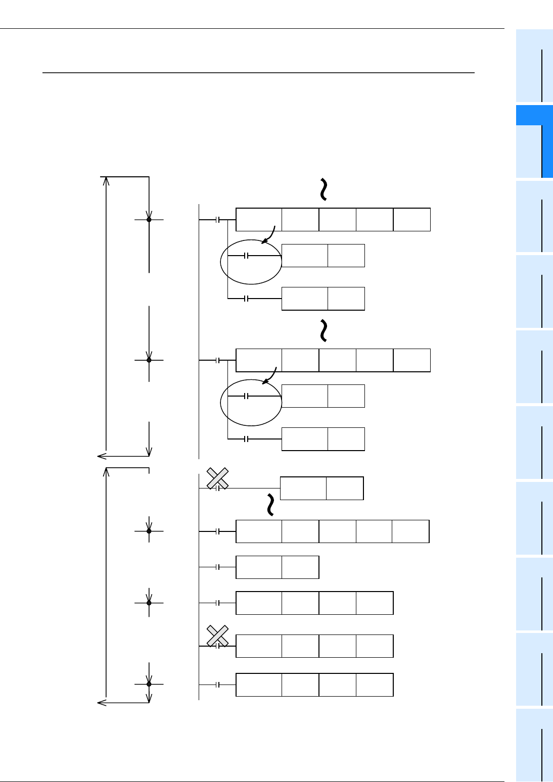
FX
3G
/FX
3U
/FX
3UC
PLC User's Manual - Positioning Control Edition
Built-in Positioning Functions
4 Before Programming
4.7 Items To Be Observed in Programming
B - 73
A
Common Items
B
Built-in
Positioning
Functions
Apx.
Example
Connection
Programming using "Instruction execution complete" flag and "Instruction execution abnormal end"
flag:
1) If two or more positioning instructions are used in a program, the "Instruction execution complete" flag
(M8029) or "Instruction execution abnormal end" flag (M8329) will be turned on or off after execution of
each instruction. However, if the "Instruction execution complete" flag (M8029) and "Instruction execution
abnormal end" flag are used together for a program, it is difficult to determine which instruction turns them
ON/OFF and the "Instruction execution complete" flag will not be turned on for the intended instruction.
→ To use a positioning instruction at a position other than just below the instruction, refer to the
example shown on the next page.
Bad
example:
The M8029 will function
as the "instruction
execution complete" flag
of the lower DSW
instruction.
The M8029 will function
as the "instruction
execution complete" flag
of the upper DPLSV
instruction.
The M8029 will function
as the "instruction
execution complete" flag
of the lower DPLSV
instruction.
RST M0
FNC 22
MUL D0 K10 D20
M8000 X10 Y10 D0
Completion of
instruction
execution
FNC 72
DSW K1
X000 M0
SET
M0 K1000 Y002 Y006
FNC157
DPLSV
M8029
M8029
Compl-
etion of instruction execution
M1 K1000 Y001 Y005
FNC157
DPLSV
Program for upper DPLSV
instruction
Program for DSW
instruction
Upper DPLSV instruction
Lower DPLSV instruction
M0 FNC158
DDRVI K100000 K50000 Y000 Y004
M0
M8029
Completion
of instruction
execution
M1 FNC159
DDRVA K10000 K30000 Y001
RST M1
M8029
M8329
The M8029 will function
as the "instruction
execution complete"
flag of DRVI instruction.
The M8029 will function
as the "instruction
execution complete"
flag of DRVA instruction.
Good
example:
Abnormal
completion of
instruction execution
M0
Y005
RST
RST
Completion
of instruction
execution
M8329 M1
RST
Abnormal
completion of
instruction execution
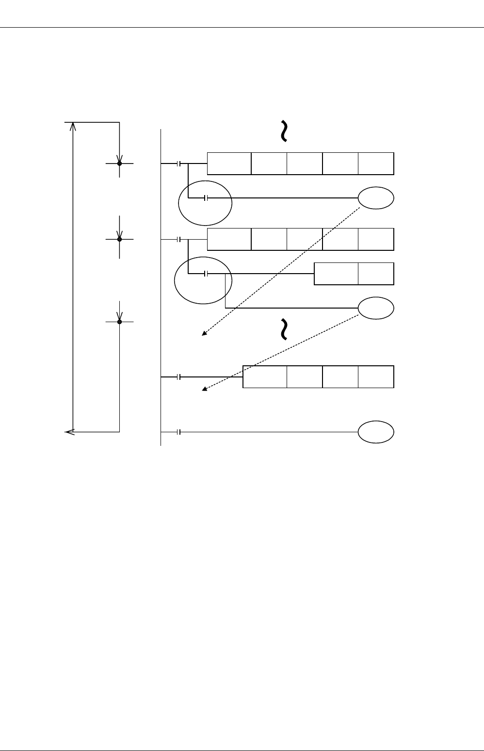
FX
3G
/FX
3U
/FX
3UC
PLC User's Manual - Positioning Control Edition
Built-in Positioning Functions
4 Before Programming
4.7 Items To Be Observed in Programming
B - 74
2) To use at a position other than just below the positioning instruction:
If two or more positioning instructions are used in a program, the "Instruction execution complete" flag
(M8029) and "Instruction execution abnormal end" flag (M8329) will be turned on or off after execution of
each instruction.
If it is necessary to use the "Instruction execution complete" flag or "Instruction execution abnormal end"
flag at a point other than just below the instruction, turn on or off another bit device just below the
instruction, and use the contact as the command contact.
M8000 FNC 72
DSW X10 Y10 D0 K1
FNC 22
MUL D0 K10 D20
M8029
Completion
of instruction
execution
M0 FNC158
DDRVI K10000 K10000 Y000
M8029
Completion
of instruction
execution
Switches "instruction
execution complete"
flag of the DSW
instruction from M8029
to M100.
M100
M200
Switches the
"instruction execution
complete" flag of the
DDRVI instruction from
M8029 to M200.
M100
Functions as the instruction
execution complete flag of
the DSW instruction.
RST M0
M200
Functions as the instruction
execution complete flag of the
DDRVI instruction.
Y030
Y004

FX
3G
/FX
3U
/FX
3UC
PLC User's Manual - Positioning Control Edition
Built-in Positioning Functions
4 Before Programming
4.7 Items To Be Observed in Programming
B - 75
A
Common Items
B
Built-in
Positioning
Functions
Apx.
Example
Connection
4.7.5 Operation Error Flag
When there is an error in the applied instruction configuration, target device or target device number range
and an error occurs while operation is executed, the following flag turns ON and the error information is
stored.
1. Operation error
• When an operation error has occurred, M8067 is set, D8067 stores the operation error code number in
which the error has occurred.
• In the FX3U/FX3UC PLC, D8315 and D8314 (32 bits) store the error occurrence step number.
When the error occurrence step is up to the 32767th step, the error occurrence step can be checked in
D8069 (16 bits).
• In the FX3G PLC, D8069 stores the error occurrence step number.
• If an operation error occurs at another step, the error code and error step number of the instruction will be
sequentially updated. (If the error status is canceled, the error flag will be turned off.)
• If the PLC is stopped and restarted without canceling the error status, the error status will be automatically
canceled, but immediately after that, the error flag will be turned on again.
2. Operation error latch
• When an operation error occurs, M8068 is turned on.
• In the FX3U/FX3UC PLC, D8313 and D8312 (32 bits) store the error occurrence step number.
When the error occurrence step is up to the 32767th step, the error occurrence step can be checked in
D8068 (16 bits).
• In the FX3G PLC, D8068 stores the error occurrence step number.
• If a new error is caused by another instruction, the error data will not be updated, and the operation will be
continued until the "forced reset" command is input or the power is turned off.
4.7.6 Write during RUN
Do not change a program if a positioning instruction (FNC150, FNC151, FNC156 to FNC159) is being
executed (pulses are being output) in the RUN mode. Operations will be performed as shown in the following
table if a program is changed during instruction execution in RUN mode.
*1. Only available for FX3U and FX3UC PLCs.
*2. Only available for FX3U/FX3UC PLC Ver. 2.20 or later and FX3G PLC.
If an FX3UC PLC is used and its version is below Ver.2.20, operation will be performed without
acceleration/deceleration.
Error flag Error code storage device Error detected step number storage device
FX3U/FX3UC PLC FX3G PLC
M8067 D8067 D8315,D8314,D8069 D8069
Error flag Error code storage device Error detected step number storage device
FX3U/FX3UC PLC FX3G PLC
M8068 - D8313,D8312,D8068 D8068
Instruction If program is changed in circuit block
including currently-activated instruction
DSZR(FNC150) Decelerates and stops pulse output.
DVIT(FNC151)*1
TBL(FNC152) Program cannot be changed in the RUN mode.
ZRN(FNC156) Decelerates and stops pulse output.
PLSV
(FNC157)
During operation with acceleration/deceleration*2 Decelerates and stops pulse output.
During operation without acceleration/deceleration Immediately stops pulse output.
DRVI(FNC158)
DRVA(FNC159) Decelerates and stops pulse output.
FX
3G
/FX
3U
/FX
3UC
PLC User's Manual - Positioning Control Edition
Built-in Positioning Functions
4 Before Programming
4.8 Items To Be Observed When Using the Main Unit (Transistor Output)
B - 76
4.8 Items To Be Observed When Using the Main Unit (Transistor Output)
1. Pulse output destination devices
Use Y000, Y001, and Y002
*1
transistor outputs of the main unit for the pulse output destination devices.
Do not use the transistor output Y003 of the main unit for positioning instructions. If Y003 is used for a positioning
instruction, PLC failure may occur.
2. Pulse output method
Adjust the pulse output method of the transistor output of the main unit to conform with the command pulse
input method of the servo amplifier (drive unit).
If the pulse output method is not properly adjusted, the servo amplifier (drive unit) may not perform the
intended operation.
→ For details on the servo amplifier (drive unit), refer to the manual of the product used in your
system.
→ For details on the pulse output method of the main unit, refer to Subsection 4.6.1.
3. Output pulse frequency (including zero return speed)
If more than 100,000 Hz pulse is output from the transistor output terminal of the main unit to perform the
operation, it may cause PLC failure.
The output pulse frequency and the zero return speed should be equal to or less than the maximum frequency
of the servo amplifier (drive unit).
4. Load current
To use a positioning instruction for the transistor output Y000, Y001, or Y002*1 of the main unit, adjust the
load current of the open collector transistor output to 10 to 100 mA (5 to 24V DC).
*1. Y002 is not available in 14-point and 24-point type FX3G PLC.
4.9 Caution for Using the High-Speed Output Special Adapter
(FX3U-2HSY-ADP)
1. Output terminals to be used
If the high-speed output special adapter is connected, output numbers will be assigned in the same way as
the main unit as shown in the following table. Use the output terminals of one side (main unit side or high-
speed output special adapter side), and do not connect lines to the output terminals of the unused side.
The outputs of the high-speed output special adapter and the main will operate as follows.
Assignment of output numbers
Item Description
Operation voltage range 5 to 24V DC
Operation current range 10 to 100mA
Output pulse frequency 100 kHz or less
Position of pulse output method
setting switch of high-speed
output special adapter
Signal
Name of
positioning
instruction
Output number
1st adapter 2nd adapter
1st axis 2nd axis 3rd axis 4th axis
FP•RP side
Forward rotation
pulse train (FP)
Pulse output
destination Y000 Y001 Y002 Y003
Reverse rotation
pulse train (RP)
Rotation
direction signal Y004 Y005 Y006 Y007
PLS•DIR side
Pulse train Pulse output
destination Y000 Y001 Y002 Y003
Direction Rotation
direction signal Y004 Y005 Y006 Y007
FX
3G
/FX
3U
/FX
3UC
PLC User's Manual - Positioning Control Edition
Built-in Positioning Functions
4 Before Programming
4.9 Caution for Using the High-Speed Output Special Adapter (FX3U-2HSY-ADP)
B - 77
A
Common Items
B
Built-in
Positioning
Functions
Apx.
Example
Connection
Operation of output
• If an output number of the high-speed output special adapter is used (if an output of the high-speed output
special adapter is connected), do not use (connect) the corresponding output terminal of the main unit.
• If an output number of the main unit is used (if an output of the main unit is connected), do not use
(connect) the corresponding output terminal of the high-speed output special adapter.
*1. The output frequency limit of the main unit transistor output is 100 kHz. When operating a load with a pulse
frequency exceeding 100 kHz, PLC failure may occur.
2. Rotation direction signal of positioning instruction
If an FX3U-2HSY-ADP high-speed output special adapter is used, the rotational direction signal will be
assigned to each pulse output destination device as shown in the following table. Do not assign any other
outputs to these devices using positioning instructions, etc.
→ For details, refer to Subsection 4.5.2.
3. CLEAR signal and rotation direction signal
If an FX3U-2HSY-ADP high-speed output special adapter is used, outputs for the rotation direction signal of
the DSZR (FNC150) or ZRN (FNC156) instruction and the CLEAR signal will overlap as shown in the table
above.
For this reason, in order to output the CLEAR signal, change the CLEAR signal device.
→ For details on the CLEAR signal device change method, refer to Subsection 4.3.4.
4. Pulse output method for high-speed output special adapter
Adjust the pulse output method of the high-speed output special adapter (FX3U-2HSY-ADP) so that the pulse
output method conforms to the command pulse input method of the servo amplifier (drive unit).
If the pulse output method is not properly adjusted, the servo amplifier (drive unit) may not perform the
intended operation.
→ For details on the servo amplifier (drive unit), refer to the manual of the product to be used for your
system.
→ For details on the pulse output method, refer to Subsection 4.6.1 or Subsection 4.5.2.
5. Output pulse frequency (including zero return speed)
Set the output pulse frequency and the zero return speed so that these values can be less than the maximum
frequency value of the servo amplifier (driver unit).
Operation of output
Instruction for outputting pulse train at high speed Other instructions
Main unit of relay output type If the instruction turns ON, the corresponding output will
be turned on (the corresponding LED will be turned on). Can be activated.
FX3U PLC main unit of transistor
output type Can be activated.*1 Can be activated.
High-speed output special adapter Can be activated. Can be activated.
Pulse output
destination device
Rotation direction signal
(reverse rotation pulse train / direction) Initial setting of
CLEAR signal
1st adapter 2nd adapter
1st axis 2nd axis 3rd axis 4th axis
Y000 Y004 - - - Y004
Y001 - Y005 - - Y005
Y002 - - Y006 - Y006
Y003 - - - Y007 Y007

FX
3G
/FX
3U
/FX
3UC
PLC User's Manual - Positioning Control Edition
Built-in Positioning Functions
4 Before Programming
4.10 Format and Execution of Applied Instruction
B - 78
4.10 Format and Execution of Applied Instruction
Instruction and operand:
- Function numbers (FNC00 - FNC) and symbols (mnemonic codes) are assigned to the applied
instructions of the PLC. For example, a symbol of "SMOV" (shift) is assigned to FNC13.
- Some applied instructions consist of the instruction area only, but many applied instructions consist of
the instruction area and the operand.
: An operand that will not be affected by the execution of the instruction is referred to as a
source. This symbol represents a source.
If the operand device number can be modified by an index register, "•" will be added, and
the S will be modified to . If there are two or more sources, the modified sources will
become , , and so on.
: An operand that will be affected by the execution of the instruction is referred to as a
destination. This symbol represents a destination.
If the device numbers can be indexed by index registers, and if there are two or more
destinations, the modified destinations will become , , and so on.
m, n : The operands not corresponding to source and destination are indicated as "m" and "n".
If the device number can be indexed by index registers, and if there are two or more
operands, the modified operands will become m1•, m2•, n1•, n2•, and so on.
- Regarding program steps, the instruction area for each applied instruction is 1 step. The operand of
each applied instruction, however, has 2 or 4 steps depending on the number of bits (16 or 32 bits).
Devices for operands:
- Bit devices X, Y, M, and S can be used for the operands, depending on the function.
- Combination of these bit devices, such as KnX, KnY, KnM, and KnS, can be used for numeric data.
→ Refer to the programming manual.
- Current value registers, such as data registers D, timers T, and counters C, can be used.
- A data register D consists of 16 bit. Two consecutive data registers (2 points) are used for 32-bit data.
For example, if data register D0 is specified for the operand of a 32-bit instruction, D1 and D0 will be
used for 32-bit data (D1 for the 16 high-order bits, and D0 for the 16 low-order bits).
If current value registers T and C are used as general data registers, they will behave the same way as
data registers.
Each 32-bit counter (C200 to C255), however, can use 32-bit data without combining two counters.
These counters, however, cannot be specified as the operands of 16-bit instructions.
Command
input FNC158
DRVI S
1
•
S
2
•
D
1
•
D
2
•
S
S
S
1
S
2
D
D
1
D
2
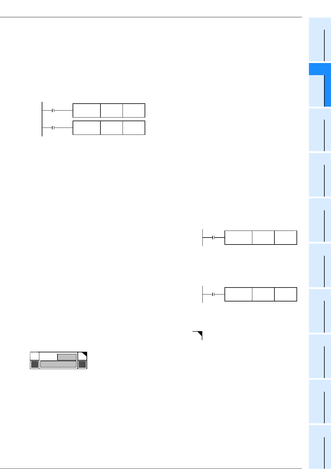
FX
3G
/FX
3U
/FX
3UC
PLC User's Manual - Positioning Control Edition
Built-in Positioning Functions
4 Before Programming
4.10 Format and Execution of Applied Instruction
B - 79
A
Common Items
B
Built-in
Positioning
Functions
Apx.
Example
Connection
Format and execution of instruction:
Depending on the sizes of the numeric values to be processed, applied instructions can be classified into two
types: 16-bit instructions and 32-bit instructions. In addition, depending on the execution type, these
instructions can also be classified into two types: continuous execution type and pulse execution type.
Depending on the applied instruction, the instruction may or may not have all the combinations.
1. 16-bit instructions and 32-bit instructions
- Depending on the bit length of the numeric data to be processed, applied instructions can be classified
into two types: 16-bit type and 32-bit type.
Move D10 to D12.
This instruction transfers data from D21 and D20 to D23
and D22.
- For the 32-bit instruction, the instruction name will be DMOV ("D" will be added to "MOV").
- Even numbered devices or odd numbered devices can be specified. If a double device is specified, the
specified device will be combined with the device with the next number (for the word devices, such as
devices T, C, and D).
To prevent confusion, it is recommended to use even numbered devices to specify the low-order bits of
an operand of a 32-bit instruction.
- Each 32-bit counter (C200 to C255) needs only one device to set 32 bits. For this reason, the operand
of a 16-bit instruction cannot specify any of the 32-bit counters.
2. Pulse execution type instructions and continuous execution type instructions
Pulse execution type instructions:
The program shown in the right figure shows that when X000 is
turned on, the instruction will be executed only once. If X000 is
off, the instruction will not be executed. If it is not necessary to
execute the instruction frequently, the pulse execution type
instruction is recommended. Note that "P" means that the
instruction of pulse execution type. This means that DMOVP is a
pulse execution type instruction.
Continuous execution type instructions:
The program shown in the right figure shows that if X001 is on,
the continuous execution type MOV instruction will be executed
at the start of each operation cycle.
Note that if FNC24 (INC) or FNC25 (DEC) is used as a continuous execution type instruction, the
destination will be changed at the start of each operation cycle.
To indicate continuous execution type instructions, the symbol " " will be added to the title of each
instruction as shown in the following figure. Use these instructions carefully.
Note that if the activation input X000 or X001 is off, instructions will not be executed. Also note that if the
later symbol is not added to the title of an instruction, the destination of the instruction will not be changed.
Command 1 FNC 12
MOV D10 D12
Command 2 FNC 12
DMOV D20 D22
X000 FNC 12
MOVP D10 D12
X001 FNC 12
MOV D10 D12
P
FNC 12
MOV
Number
Instruction name
D
FX
3G
/FX
3U
/FX
3UC
PLC User's Manual - Positioning Control Edition
Built-in Positioning Functions
5 Operation Test
B - 80
5. Operation Test
This chapter describes the operation test of positioning instructions. During forward rotation (JOG+)
operation and reverse rotation (JOG-) operation, the test checks whether positioning instructions are properly
activated.
DESIGN PRECAUTIONS
• Make sure to have the following safety circuits outside of the PLC to ensure safe system operation even during
external power supply problems or PLC failure.
Otherwise, malfunctions may cause serious accidents.
1) Most importantly, have the following: an emergency stop circuit, a protection circuit, an interlock circuit for
opposite movements (such as normal vs. reverse rotation), and an interlock circuit (to prevent damage to the
equipment at the upper and lower positioning limits).
2) Note that when the PLC CPU detects an error, such as a watchdog timer error, during self-diagnosis, all
outputs are turned off. Also, when an error that cannot be detected by the PLC CPU occurs in an input/output
control block, output control may be disabled.
External circuits and mechanisms should be designed to ensure safe machinery operation in such a case.
3) Note that when an error occurs in a relay, triac or transistor output device, the output could be held either on or
off.
For output signals that may lead to serious accidents, external circuits and mechanisms should be designed to
ensure safe machinery operation in such a case.
DESIGN PRECAUTIONS
• Do not bundle the control line together with or lay it close to the main circuit or power line. As a guideline, lay the
control line at least 100mm (3.94") or more away from the main circuit or power line.
Noise may cause malfunctions.
• Install module so that excessive force will not be applied to the built-in programming port, power connectors, I/O
connectors, communication connectors, or communication cables.
Failure to do so may result in wire damage/breakage or PLC failure.
WIRING PRECAUTIONS
• Make sure to cut off all phases of the power supply externally before attempting installation or wiring work.
Failure to do so may cause electric shock or damage to the product.
• Make sure to attach the terminal cover, offered as an accessory, before turning on the power or initiating operation
after installation or wiring work.
Failure to do so may cause electric shock.
WIRING PRECAUTIONS
• Connect the AC power supply to the dedicated terminals specified in the manual of the PLC main unit.
If an AC power supply is connected to a DC input/output terminal or DC power supply terminal, the PLC will burn
out.
• Connect the DC power supply to the dedicated terminals specified in the manual of the PLC main unit.
If an AC power supply is connected to a DC input/output terminal or DC power supply terminal, the PLC will burn
out.
• Do not wire vacant terminals externally.
Doing so may damage the product.
• Perform class D grounding (grounding resistance: 100Ω or less) to the grounding terminal on the FX3U/FX3G PLC
main unit with a wire 2 mm2 or thicker.
Do not use common grounding with heavy electrical systems (refer to the manual of the PLC main unit).
• Perform class D grounding (grounding resistance: 100Ω or less) to the grounding terminal on the main unit.
Do not use common grounding with heavy electrical systems.
• When drilling screw holes or wiring, make sure cutting or wire debris does not enter the ventilation slits.
Failure to do so may cause fire, equipment failures or malfunctions.
FX
3G
/FX
3U
/FX
3UC
PLC User's Manual - Positioning Control Edition
Built-in Positioning Functions
5 Operation Test
B - 81
A
Common Items
B
Built-in
Positioning
Functions
Apx.
Example
Connection
• Install module so that excessive force will not be applied to I/O connectors.
Failure to do so may result in wire damage/breakage or PLC failure.
• Connect input/output cables securely to their designated connectors.
Loose connections may cause malfunctions.
• Make sure to properly wire the FX3U/FX3G Series main unit and FX0N/FX2N Series extension equipment in
accordance with the following precautions.
Failure to do so may cause electric shock, a short-circuit, wire breakage, or damage to the product.
- The disposal size of the cable end should follow the dimensions described in this manual.
- Tightening torque should be between 0.5 and 0.8 N•m.
• Make sure to properly wire to the European terminal board in accordance with the following precautions.
Failure to do so may cause electric shock, a short-circuit, wire breakage, or damage to the product.
- The disposal size of the cable end should follow the dimensions described in this manual.
- Tightening torque should be between 0.22 and 0.25 N•m.
- Twist the end of strand wire and make sure that there are no loose wires.
- Do not solder-plate the electric wire ends.
- Do not connect more than the specified number of wires or electric wires of unspecified size.
- Affix the electric wires so that neither the terminal block nor the connected parts are directly stressed.
• Make sure to properly wire to the FX Series terminal blocks in accordance with the following precautions.
Failure to do so may cause electric shock, a short-circuit, wire breakage, or damage to the product.
- The disposal size of the cable end should follow the dimensions described in this manual.
- Tightening torque should be between 0.5 and 0.8 N•m.
STARTUP AND MAINTENANCE
PRECAUTIONS
• Do not touch any terminal while the PLC's power is on.
Doing so may cause electric shock or malfunctions.
• Before cleaning or retightening terminals, cut off all phases of the power supply externally.
Failure to do so may cause electric shock.
• Before modifying or disrupting the program in operation or running the PLC, carefully read through this manual
and the associated manuals and ensure the safety of the operation.
An operation error may damage the machinery or cause accidents.
STARTUP AND MAINTENANCE
PRECAUTIONS
• Do not disassemble or modify the PLC.
Doing so may cause fire, equipment failures, or malfunctions.
For repair, contact your local Mitsubishi Electric distributor.
• Turn off the power to the PLC before connecting or disconnecting any extension cable.
Failure to do so may cause equipment failures or malfunctions.
• Turn off the power to the PLC before attaching or detaching the following devices.
Failure to do so may cause equipment failures or malfunctions.
- Peripheral devices, expansion boards, and special adapters
- Input/output extension units/blocks and FX Series terminal blocks
WIRING PRECAUTIONS

FX
3G
/FX
3U
/FX
3UC
PLC User's Manual - Positioning Control Edition
Built-in Positioning Functions
5 Operation Test
5.1 Test Procedure
B - 82
5.1 Test Procedure
1Turn off the power to the PLC.
2Temporarily connect the limit switches (forward rotation limit 1, reverse
rotation limit 1) and the manual switches (forward rotation, reverse rotation).
Connect the limit switches and the manual switches to the following input terminals of the PLC.
Do not connect the servo amplifier (drive unit).
→ For details on connection, refer to Chapter 3 of the Hardware Edition of the PLC.
→ For details on the forward rotation limit and the reverse rotation limit, refer to Subsection 4.3.1.
3Create the test program.
→ For details on the test program, refer to Section 5.2.
4Turn on the power to the PLC.
5Transfer the test program to the main unit.
→ For details, refer to the manual of the programming tool.
6Check the input indicator lamp (LED lamp).
When the programming controller is stopped, activate the temporarily connected input terminals,
and check the status of each input indicator lamp (LED lamp).
If an FX3UC-32MT-LT(-2) PLC is used, check the input statuses using the display module.
7Switch the PLC into RUN mode.
Signal Input number
Limit switch Forward rotation limit 1 NC contact X010
Reverse rotation limit 1 NC contact X011
Manual switch Forward rotation (JOG+) NO contact X012
Reverse rotation (JOG-) NO contact X013
Signal Input signal Status of LED indicator lamp
Forward rotation limit 1 X010 Activation of the forward rotation limit switch 1 will turn off the LED
indicator lamp of X010 (turn off X010).
Reverse rotation limit 1 X011 Activation of the reverse rotation limit switch 1 will turn off the LED
indicator lamp of X011 (turn off X011).
Forward rotation (JOG+) X012 Turning on the forward rotation (JOG+) switch will turn on the LED
indicator lamp of X012.
Reverse rotation (JOG-) X013 Turning on the reverse rotation (JOG-) switch will turn on the LED
indicator lamp of X013.

FX
3G
/FX
3U
/FX
3UC
PLC User's Manual - Positioning Control Edition
Built-in Positioning Functions
5 Operation Test
5.1 Test Procedure
B - 83
A
Common Items
B
Built-in
Positioning
Functions
Apx.
Example
Connection
8Check the operation in the forward rotation direction.
Check the output indicator lamp (LED lamp) and the current value register to monitor the operation.
The status of the LED indicator lamp and the value indicated in the current value register depend
on the pulse output destination or rotation direction set by the positioning instruction. However, if
the pulse output destination or the rotation direction is changed for the test program, carefully read
the status of the output indicator lamp (LED lamp) and the value indicated in the current value
register to monitor the change.
1. Operation in forward rotation direction
Turn on the forward rotation (JOG+) switch (X012), and verify that the operation is performed in the
forward rotation direction. For this check, set the other inputs as follows:
1) LED indicator lamp check
Check the LED indicator lamps of the PLC or the display module to see whether or not the outputs are
turned on. The status of each output should be as shown in the following table:
2) Current value register (D8341, D8340) check
Monitor the current value register (D8341, D8340) of the FX3U/FX3UC/FX3G PLC using the programming
tool, and confirm that the value is being increased.
→ For details on the current value register, refer to Subsection 4.4.1.
2. Stop of operation
Turn off the forward rotation (JOG+) switch (X012) to stop the operation in the forward rotation direction.
1) LED indicator lamp check
Check the LED indicator lamps of the PLC or the display module to check whether the outputs are turned
on. The status of each output should be as shown in the following table:
2) Current value register (D8341, D8340) check
Monitor the current value register (D8341, D8340) of the FX3U/FX3UC/FX3G PLC using the programming
tool, and confirm that the value is not being increased.
→ For details on the current value register, refer to Subsection 4.4.1.
Input signal Status
X010 ON
X011 ON
X013 OFF
Pulse output
method
LED lamp of
output Status of LED lamp (output)
If transistor outputs of the
main unit are used
"Pulse train + direc-
tion" method
Y000 Turned on and off at high speed.
Y004 Kept ON.
If a high-speed output
special adapter is used
"Pulse train + direc-
tion" method
Y0/2 Turned on and off at high speed.
Y4/6 Kept ON.
Forward rotation
pulse train (FP)
Reverse rotation
pulse train (RP)
Y0/2 Turned on and off at high speed.
Y4/6 Kept OFF.
Pulse output
method
LED lamp
of output Status of LED lamp (output)
If transistor outputs of the
main unit are used
"Pulse train + direc-
tion" method
Y000 The LED indicator lamp (turned on and
off at high speed) will be turned off.
Y004 Kept ON.
If the high-speed output
special adapter is used
"Pulse train + direc-
tion" method
Y0/2 The LED indicator lamp (turned on and
off at high speed) will be turned off.
Y4/6 Kept ON.
Forward rotation
pulse train (FP)
Reverse rotation
pulse train (RP)
Y0/2 The LED indicator lamp (turned on and
off at high speed) will be turned off.
Y4/6 Kept OFF.

FX
3G
/FX
3U
/FX
3UC
PLC User's Manual - Positioning Control Edition
Built-in Positioning Functions
5 Operation Test
5.1 Test Procedure
B - 84
9Check the operation of the forward rotation limit switch.
During operation in the forward rotation direction (at step 8), turn off the forward rotation limit switch
1 (X010), and confirm that the operation in the forward rotation direction is stopped.
The LED indicator lamps and the current value register (D8341, D8340) will enter the same
statuses as the stop statuses described in step 8.
In addition, the "Instruction execution abnormal end" flag (M8329) will turn on.
→ For details on the current value register, refer to Subsection 4.4.1.
10 Check the operation in the reverse rotation direction.
Check the output indicator lamp (LED lamp) and the current value register to monitor the operation.
The status of the LED indicator lamp and the value indicated in the current value register depend
on the pulse output destination or rotation direction set by the positioning instruction. However, if
the pulse output destination or the rotation direction is changed for the test program, carefully read
the status of the output indicator lamp (LED lamp) and the value indicated in the current value
register to monitor the change.
1. Operation in reverse rotation direction
Turn on the reverse rotation (JOG-) switch (X013), and verify that the operation is performed in the
reverse rotation direction. For this check, set the other inputs as follows:
1) LED indicator lamp check
Check the LED indicator lamps of the PLC or the display module to check whether the outputs are turned
on. The status of each output should be as shown in the following table:
2) Current value register (D8341, D8340) check
Monitor the current value register (D8341, D8340) of the FX3U/FX3UC/FX3G PLC using the programming
tool, and confirm that the value is being reduced.
→ For details on the current value register, refer to Subsection 4.4.1.
Input signal Status
X010 ON
X011 ON
X012 OFF
Pulse output
method
LED lamp
of output Status of LED lamp (output)
If transistor outputs of the
main unit are used
"Pulse train + direc-
tion" method
Y000 Turned on and off at high speed.
Y004 Kept OFF.
If high-speed output
special adapter is used
"Pulse train + direc-
tion" method
Y0/2 Turned on and off at high speed.
Y4/6 Kept OFF.
Forward rotation
pulse train (FP)
Reverse rotation
pulse train (RP)
Y0/2 Kept OFF.
Y4/6 Turned on and off at high speed.

FX
3G
/FX
3U
/FX
3UC
PLC User's Manual - Positioning Control Edition
Built-in Positioning Functions
5 Operation Test
5.1 Test Procedure
B - 85
A
Common Items
B
Built-in
Positioning
Functions
Apx.
Example
Connection
2. Stop of operation
Turn off the reverse rotation (JOG-) switch (X013) to stop the operation in the reverse rotation direction.
1) LED indicator lamp check
Check the LED indicator lamps of the PLC or the display module to check whether or not the outputs are
turned on. The status of each output should be as shown in the following table:
2) Current value register (D8341, D8340) check
Monitor the current value register (D8341, D8340) of the FX3U/FX3UC/FX3G PLC using the programming
tool, and confirm that the value is not being decreased.
→ For details on the current value register, refer to Subsection 4.4.1.
11 Check the operation of the reverse rotation limit switch.
During operation in the reverse rotation direction (at step 10), turn off the reverse rotation limit
switch 1 (X011), and confirm that the operation in the reverse rotation direction is stopped.
The LED indicator lamps and the current value register (D8341, D8340) will enter the same
statuses as the stop statuses described in step 10.
In addition, the "Instruction execution abnormal end" flag (M8329) will turn on.
→ For details on the current value register, refer to Subsection 4.4.1.
Pulse output
method
LED lamp
of output Status of LED lamp (output)
If transistor outputs of main
unit are used
"Pulse train + direc-
tion" method
Y000 The LED indicator lamp (turned on and
off at high speed) will be turned off.
Y004 Kept OFF.
If high-speed output
special adapter is used
"Pulse train + direc-
tion" method
Y0/2 The LED indicator lamp (turned on and
off at high speed) will be turned off.
Y4/6 Kept OFF.
Forward rotation
pulse train (FP)
Reverse rotation
pulse train (RP)
Y0/2 Kept OFF.
Y4/6 The LED indicator lamp (turned on and
off at high speed) will be turned off.

FX
3G
/FX
3U
/FX
3UC
PLC User's Manual - Positioning Control Edition
Built-in Positioning Functions
5 Operation Test
5.2 Creation of Test Program
B - 86
5.2 Creation of Test Program
1. Input/output assignment
Inputs/outputs are assigned as shown in the following table:
2. Setting of related devices
The following related devices depend on the pulse output destination device that is set for the positioning
instruction. If the pulse output destination device is changed, it is necessary to change the related devices.
→ For setting items of the related devices, refer to Subsection 4.5.1.
Signal Input/output number
Limit switch Forward rotation limit 1 NC contact X010
Reverse rotation limit 1 NC contact X011
Manual switch Forward rotation (JOG+) NO contact X012
Reverse rotation (JOG-) NO contact X013
"Pulse train" signal or "forward rotation pulse train" signal (output specified for pulse output
destination) Y000
"Direction" signal or "reverse rotation pulse train" signal (output specified for rotation
direction signal) Y004
Setting item Description of setting Related
device
Setting value or
condition
Items related to speed
Maximum speed 100,000Hz D8344,D8343
(32-bit) K100000 Initial value
Bias speed 0Hz D8342 K0 Initial value
Acceleration time 100ms D8348 K100 Initial value
Deceleration time 100ms D8349 K100 Initial value
Forward/reverse rotation speed 30,000Hz - K30000 -
Forward limit, reverse limit, and immediate stop of pulse output
Forward limit
If X010 is turned off (if the NC contact is
turned on), the limit switch will be
activated.
M8343 ON: If X010 = OFF
Reverse limit
If X011 is turned off (if the NC contact is
turned on), the limit switch will be
activated.
M8344 ON: If X011 = OFF
Status check items
Positioning (Y000)
Use this device to check whether the
positioning instruction is being
activated.
M8348
Turns on when the
positioning instruction is
activated.
"Instruction execution abnormal
end" flag
Use this device to check whether or not
the forward/reverse rotation limit switch
turns ON.
M8329
Turns on when the limit
switch is activated
during a positioning
operation.
Current value register (Y000) Stores the current value of the
positioning operation in Y000.
D8341,D8340
(32-bit)
Varies when a positioning
instruction tuns ON.
FX
3G
/FX
3U
/FX
3UC
PLC User's Manual - Positioning Control Edition
Built-in Positioning Functions
5 Operation Test
5.2 Creation of Test Program
B - 87
A
Common Items
B
Built-in
Positioning
Functions
Apx.
Example
Connection
3. Example program
Performs jogging operation
in the forward rotation direction
using the drive to Increment
instruction.
M8002 Maximum speed (for Y000)
100,000Hz
→
[D8344,D8343]
Bias speed (for Y000)
0Hz
→
D8342
Acceleration time (for Y000)
100ms
→
D8348
Deceleration time (for Y000)
100ms
→
D8349
D8343K100000
FNC 12
DMOV
D8342K0
FNC 12
MOV
D8348K100
D8349K100
FNC 12
MOV
FNC 12
MOV
X012
JOG+
M8348
Positioning
(Y000)
M101
JOG(+)
operation
completed
Y004Y000
FNC158
DDRVI K30000K999999
X012
JOG+
M8329
Instruction execution
abnormal completion
M101
Forward limit (for Y000)M8343
X010
Reverse limit (for Y000)
M8344
X011
Completes the JOG+ operation.
X013
JOG-
M8348
Positioning
(Y000)
M103 Y004Y000
FNC158
DDRVI K30000K-999999
X013
JOG-
M8329
Instruction execution
abnormal completion
M103
Performs jogging operation in the
reverse rotation direction using the
drive to Increment instruction.
Completes the JOG- operation.
END
Initial pulse
Forward rotation limit 1
Reverse rotation limit 1
JOG(-)
operation
completed
M100
JOG(+)
operation
being
performed
M100 JOG+ operation is being performed.
M102 JOG- operation is being performed.
M102
JOG(-)
operation
being
performed

FX
3G
/FX
3U
/FX
3UC
PLC User's Manual - Positioning Control Edition
Built-in Positioning Functions
6 Mechanical Zero Return (DSZR/ZRN Instruction)
6.1 Types of Mechanical Zero Return Instructions
B - 88
6. Mechanical Zero Return (DSZR/ZRN Instruction)
6.1 Types of Mechanical Zero Return Instructions
If forward rotation pulses or reverse rotation pulses are being output, the positioning instruction of the PLC will
increase or decrease the current value of the current value register.
When turning off the power of the PLC, however, the current value stored in the current value register will be
erased. For this reason, after turning on the power again, be sure to adjust the current value of the current
value register to the current position of the machine.
The built-in positioning function uses the DSZR/ZRN instruction (zero return instruction) to adjust the value of
the current value register to the current mechanical position.
Compared with the ZRN instruction, the DSZR instruction has additional functionality.
Absolute position detection system:
If the MR-H, MR-J2, MR-J2S, or MR-J3 servo amplifier (with absolute position detection function)
manufactured by Mitsubishi is used, the current position value will be retained even after power-off.
To use the absolute position detection system, zero return is required to be performed only once. The PLC
can then read the current position value of the servo motor with the FNC155 (DABS) instruction. With this
method, it is not necessary to perform zero return every time after power-on.
DSZR instruction ZRN instruction
DOG search function 3-
DOG signal logical NOT 3-
Zero return using zero-phase signal 3-
Zero point signal logic reverse 3-
FX
3G
/FX
3U
/FX
3UC
PLC User's Manual - Positioning Control Edition
Built-in Positioning Functions
6 Mechanical Zero Return (DSZR/ZRN Instruction)
6.2 DOG Search Zero Return (DSZR Instruction)
B - 89
A
Common Items
B
Built-in
Positioning
Functions
Apx.
Example
Connection
6.2 DOG Search Zero Return (DSZR Instruction)
Use this instruction to change the CLEAR signal output destination with an FX3U/FX3UC PLC Ver.2.20 or later
or an FX3G PLC.
6.2.1 Instruction Format
1. Instruction format
2. Data setting
3. Devices
1:D.b is available only in FX3U and FX3UC PLCs. However, index modifiers (V and Z) are not available.
2 : Specify a device in the range of X000 to X007.
3 : Specify Y000, Y001, or Y002*1 transistor output from the main unit, or specify Y000, Y001, Y002*3, or
Y003*3 from a high-speed output special adapter*2.
*1. Y002 is not available in 14-point and 24-point type FX3G PLC.
*2. High-speed input/output special adapters can be connected only to the FX3U PLC.
*3. To use Y002 and Y003 of a high-speed output special adapter, connect a second high-speed output
special adapter.
Note:
• To use an FX3U Series main unit of relay output type, be sure to connect a high-speed output special
adapter. Differential line drive type outputs will be used for the outputs of the high-speed output special
adapter.
Operand type Description Data type
Specifies the near-point signal (DOG) input device number.
Bit
Specifies the zero-phase signal input number.
Specifies the pulse output number.
Specifies the rotation direction signal output destination number.
Operand
type
Bit device Word device Others
System user Digit designation System user Spe-
cial unit Index Con-
stant
Real
num-
ber
Char-
acter
string
Pointer
XYMTCSD
.b KnX KnY KnM KnS T C D R U\GV Z Modify K H E ""P
333 3 13
23
33
43313
FNC 150
DSZR
ZERO RETURN
WITH DOG
SEARCH
16-bit
instruction
9 steps DSZR
-
Continuous
execution
type
Instruction
symbol Execution condition 32-bit
instruction
-
-
Instruction
symbol Execution condition
Command
input
FNC 150
DSZR S
2
•
S
1
•
D
1
•
D
2
•
S
1
S
2
D
1
D
2
S
1
S
2
D
1
D
2
FX
3G
/FX
3U
/FX
3UC
PLC User's Manual - Positioning Control Edition
Built-in Positioning Functions
6 Mechanical Zero Return (DSZR/ZRN Instruction)
6.2 DOG Search Zero Return (DSZR Instruction)
B - 90
4 : When a high-speed output special adapter is used as a destination for pulse output on a FX3U PLC,
use the output shown in the following table for rotation direction signals.
When a built-in transistor output is used as a destination for pulse output on a FX3U/FX3UC/FX3G PLC,
use transistor output for signals rotation direction.
→ For the outputs applicable with a High-speed output special adapter, refer to Section 4.9.
6.2.2 List of Related devices
1. Special auxiliary relays
The following table shows the related special auxiliary relays. Note that Y000, Y001, Y002, and Y003 are
devices that determine the pulse output destinations.
*1. Y002 is not available in 14-point and 24-point type FX3G PLC.
*2. Devices related to Y003 (pulse output destination) are only valid if two FX3U-2HSY-ADP adapters are
connected to the FX3U PLC.
*3. Cleared when PLC switches from RUN to STOP.
*4. Only available for FX3U/FX3UC PLC Ver. 2.20 or later and FX3G PLC.
High-speed output special
adapter connection position Pulse output Rotation direction output
1st adapter = Y000 = Y004
= Y001 = Y005
2nd adapter = Y002 = Y006
= Y003 = Y007
Device number Function Attribute Refer to
Y000 Y001 Y002*1 Y003*2
M8029 "Instruction execution complete" flag Read only Subsection
4.4.2
M8329 "Instruction execution abnormal end" flag Read only Subsection
4.4.2
M8340 M8350 M8360 M8370 "Pulse output monitor" (BUSY/READY) flag Read only Subsection
4.4.3
M8341 M8351 M8361 M8371 CLEAR signal output function enable*3 Drivable Subsection
4.3.4
M8342 M8352 M8362 M8372 Zero return direction specification*3 Drivable Subsection
4.3.3
M8343 M8353 M8363 M8373 Forward limit Drivable Subsection
4.3.1
M8344 M8354 M8364 M8374 Reverse limit Drivable Subsection
4.3.1
M8345 M8355 M8365 M8375 DOG signal logic reverse*3 Drivable Subsection
4.3.5
M8346 M8356 M8366 M8376 Zero point signal logic reverse*3 Drivable Subsection
4.3.6
M8348 M8358 M8368 M8378 Positioning instruction activation Read only Subsection
4.4.4
M8349 M8359 M8369 M8379 Pulse output stop command*3 Drivable Subsection
4.3.2
M8464 M8465 M8466 M8467 CLEAR signal device specification function
enabled*3, *4 Drivable Subsection
4.3.4
D
1
D
2
D
1
D
2
D
1
D
2
D
1
D
2

FX
3G
/FX
3U
/FX
3UC
PLC User's Manual - Positioning Control Edition
Built-in Positioning Functions
6 Mechanical Zero Return (DSZR/ZRN Instruction)
6.2 DOG Search Zero Return (DSZR Instruction)
B - 91
A
Common Items
B
Built-in
Positioning
Functions
Apx.
Example
Connection
2. Special data registers
The following table shows the related special data registers. Note that Y000, Y001, Y002, and Y003 are
devices that determine the pulse output destinations.
*1. Y002 is not available in 14-point and 24-point type FX3G PLC.
*2. Devices related to Y003 (pulse output destination) are only valid if two FX3U-2HSY-ADP adapters are
connected to the FX3U PLC.
*3. Only available for FX3U/FX3UC PLC Ver. 2.20 or later and FX3G PLC.
Device number Function Data
length
Initial
value Refer to
Y000 Y001 Y002*1 Y003*2
D8340 Low-
order D8350 Low-
order D8360 Low-
order D8370 Low-
order Current value
register (PLS) 32-bit 0 Subsection
4.4.1
D8341 High-
order D8351 High-
order D8361 High-
order D8371 High-
order
D8342 D8352 D8362 D8372 Bias speed
(Hz) 16-bit 0 Subsection
4.2.6
D8343 Low-
order D8353 Low-
order D8363 Low-
order D8373 Low-
order Maximum
speed (Hz) 32-bit 100,000 Subsection
4.2.5
D8344 High-
order D8354 High-
order D8364 High-
order D8374 High-
order
D8345 D8355 D8365 D8375 Creep speed
(Hz) 16-bit 1000 Subsection
4.2.4
D8346 Low-
order D8356 Low-
order D8366 Low-
order D8376 Low-
order Zero return
speed (Hz) 32-bit 50,000 Subsection
4.2.3
D8347 High-
order D8357 High-
order D8367 High-
order D8377 High-
order
D8348 D8358 D8368 D8378 Acceleration
time (ms) 16-bit 100 Subsection
4.2.7
D8349 D8359 D8369 D8379 Deceleration
time (ms) 16-bit 100 Subsection
4.2.8
D8464 D8465 D8466 D8467
CLEAR signal
device
specification
*3
16-bit - Subsection
4.3.4
FX
3G
/FX
3U
/FX
3UC
PLC User's Manual - Positioning Control Edition
Built-in Positioning Functions
6 Mechanical Zero Return (DSZR/ZRN Instruction)
6.2 DOG Search Zero Return (DSZR Instruction)
B - 92
6.2.3 Function and Operation
→ For details on the maximum speed, bias speed, acceleration time, and deceleration time, refer to
Subsection 4.2.5 to Subsection 4.2.8.
1) For , specify the near-point signal (DOG) input device number. To specify the logic of this near-
point signal (DOG), turn the "DOG signal logic reverse" relay on or off as shown in the following table.
• When an input (X000 to X017)*1 from the main unit is used for the near-point signal (DOG)
, the rear end of the near-point signal (DOG) will be monitored (detected) at 1-ms intervals
(interruption).
Under the following condition, however, monitoring (detection) of the near-point signal (DOG) rear end
will be affected by the input constant or the scan time of the sequence program:
- An input number of X020 or below (or other device (auxiliary relay, etc.)) is specified.
*1. Specify X000 to X007 for FX3U-16M, FX3UC-16M.
Specify X000 to X007 for FX3G PLC (main unit).
Pulse output
destination device
"DOG signal logic
reverse" relay Description
= Y000 M8345 OFF: Positive logic (Turning on the input will turn on the
near-point signal.)
ON: Negative logic (Turning off the input will turn on the
near-point signal.)
= Y001 M8355
= Y002 M8365
= Y003 M8375
Command
input
FNC 150
DSZR S
2
•
S
1
•
D
1
•
D
2
•
Maximum speed
Initial value: 100,000Hz
Zero return speed
Initial value: 50,000Hz
Deceleration
time
Bias speed
Initial value: 0Hz
Acceleration
time
Creep speed
Initial value:
1,000Hz
CLEAR signal
Zero-phase signal
(X000 - X007)
1 ms or less
20 ms + 1 scan time (ms)
S
2
•
Current value register = "0"
Initial value:
100 ms
Initial value:
100ms
DOG S
1
•
Front endRear end
S
1
D
1
D
1
D
1
D
1
S
1
FX
3G
/FX
3U
/FX
3UC
PLC User's Manual - Positioning Control Edition
Built-in Positioning Functions
6 Mechanical Zero Return (DSZR/ZRN Instruction)
6.2 DOG Search Zero Return (DSZR Instruction)
B - 93
A
Common Items
B
Built-in
Positioning
Functions
Apx.
Example
Connection
2) For , specify the zero-phase signal input number in the range of X000 to X007. To specify the logic
of this zero-phase signal, turn the "Zero point signal logic reverse" relay on or off as shown in the
following table.
If the same input is specified for both the near-point signal and the zero-phase signal, the logic of the zero-
phase signal will be specified by the device of the near-point signal (DOG), and not by one of the following
devices. In this case, the operation will be performed at the front and rear ends of the near-point signal
(DOG) without using the zero-phase signal. This is similar to the operation of the ZRN instruction.
3) For , specify a pulse output number in the range of Y000 to Y003.
4) For , specify the rotation direction signal output device number.
When a high-speed output special adapter is used as a destination for pulse output on a FX3U PLC, use
the output shown in the following table for rotation direction signals.
When a built-in transistor output is used as a destination for pulse output on a FX3U/FX3UC/FX3G PLC,
use transistor output for signals rotation direction.
The rotation direction ON/OFF status of the specified device is shown in the following table.
During instruction execution, however, do not use the output for other purposes.
5) Zero return direction
To specify the zero return direction, turn "zero return direction specification" relay on or off as shown in
the following table.
Pulse output
destination device
"Zero point signal logic
reverse" flag Description
= Y000 M8346 OFF: Positive logic (Turning on the input will turn on the
near-point signal.)
ON: Negative logic (Turning off the input will turn on the
near-point signal.)
= Y001 M8356
= Y002 M8366
= Y003 M8376
High-speed output special
adapter connection position Pulse output Rotation direction
output
1st adapter = Y000 = Y004
= Y001 = Y005
2nd adapter = Y002 = Y006
= Y003 = Y007
ON/OFF status of device
specified by Rotation direction (increase/decrease current value)
ON Forward rotation (Outputting pulses from will increase the
current value.)
OFF Reverse rotation (Outputting pulses from will decrease the
current value.)
Pulse output
destination device
"Zero return direction
specification" relay Description
= Y000 M8342 To perform zero return in the
forward rotation direction: Turn on the relay.
To perform zero return in the
reverse rotation direction: Turn off the relay.
= Y001 M8352
= Y002 M8362
= Y003 M8372
S
2
D
1
D
1
D
1
D
1
D
1
D
2
D
1
D
2
D
1
D
2
D
1
D
2
D
1
D
2
D
2
D
2
D
1
D
1
D
1
D
1
D
1
D
1
FX
3G
/FX
3U
/FX
3UC
PLC User's Manual - Positioning Control Edition
Built-in Positioning Functions
6 Mechanical Zero Return (DSZR/ZRN Instruction)
6.2 DOG Search Zero Return (DSZR Instruction)
B - 94
6) CLEAR signal output
This instruction can output the CLEAR signal after stopping at the origin.
If it is necessary to output the CLEAR signal at the completion of zero return, turn on the "CLEAR signal
output function enable" relay (see the following table).
Use an FX3U/FX3UC PLC Ver.2.20 or later or FX3G PLC to specify the CLEAR signal output device.
a) If it is not necessary to use the CLEAR signal device specification function, or if an FX3UC PLC below
Ver.2.20 is used.
*1. Use an FX
3U
/FX
3UC
PLC Ver.2.20 or later or FX
3G
PLC to use the "
CLEAR
signal device specification function
enable" relay.
b) If it is necessary to use the CLEAR signal device specification
function:
Turn on the "CLEAR signal device specification function enable"
relay to specify the CLEAR signal output device (output Y) for the pulse output destination device
using the CLEAR signal device specification register.
→ For an example program, refer to Subsection 4.3.4 or Subsection 4.5.1.
7) Zero return speed
Use the devices shown in the following table to set the zero return speed. Be sure to set the zero return
speed so that the relation with the other speeds is "bias speed ≤ zero return speed ≤ maximum speed".
- If "zero return speed > maximum speed", the operation will be performed at the maximum speed.
8) Creep speed
Use the devices shown in the following table to set the creep speed. Be sure to set the creep speed so
that the relation with the other speeds is "bias speed ≤ creep speed ≤ maximum speed".
Pulse output
destination device
Status of "CLEAR
signal output function
enable" relay
Status of "CLEAR signal
device specification function
enable" relay*1
CLEAR signal device
number
= Y000 M8341=ON M8464=OFF Y004
= Y001 M8351=ON M8465=OFF Y005
= Y002 M8361=ON M8466=OFF Y006
= Y003 M8371=ON M8467=OFF Y007
Pulse output
destination device
Status of "CLEAR
signal output function
enable" relay
Status of "CLEAR signal
device specification function
enable" relay*1
CLEAR signal device
specification register
= Y000 M8341=ON M8464=ON D 8464
= Y001 M8351=ON M8465=ON D 8465
= Y002 M8361=ON M8466=ON D 8466
= Y003 M8371=ON M8467=ON D 8467
Pulse output
destination device Bias speed Zero return speed Maximum speed Initial value
= Y000 D8342 D8347,D8346 D8344,D8343
50,000(Hz)
= Y001 D8352 D8357,D8356 D8354,D8353
= Y002 D8362 D8367,D8366 D8364,D8363
= Y003 D8372 D8377,D8376 D8374,D8373
Pulse output
destination device Bias speed Creep speed Maximum speed Initial value
= Y000 D8342 D8345 D8344,D8343
1,000(Hz)
= Y001 D8352 D8355 D8354,D8353
= Y002 D8362 D8365 D8364,D8363
= Y003 D8372 D8375 D8374,D8373
D
1
D
1
D
1
D
1
D
1
D
1
D
1
D
1
D
1
D
1
D
1
D
1
D
1
D
1
D
1
D
1
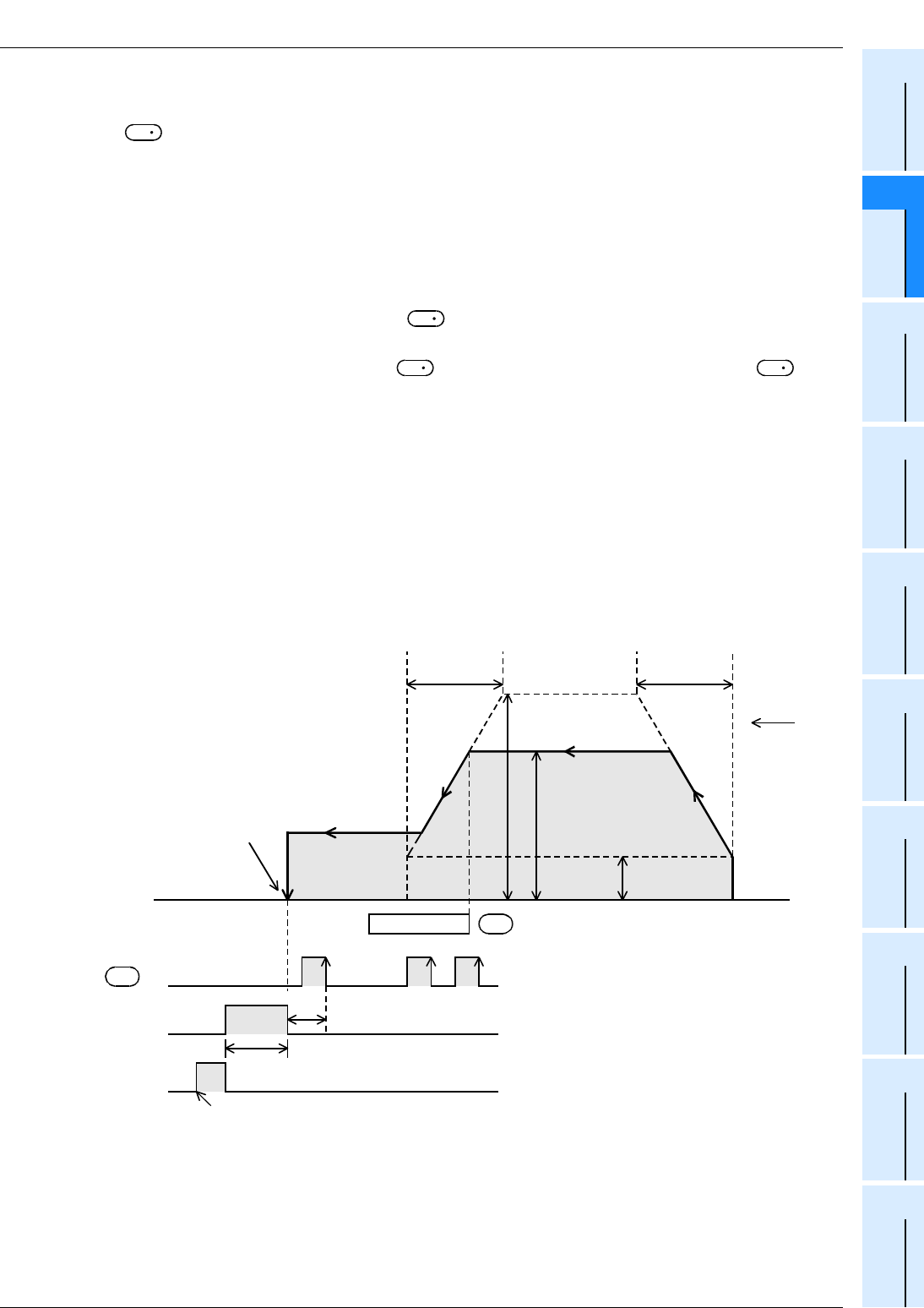
FX
3G
/FX
3U
/FX
3UC
PLC User's Manual - Positioning Control Edition
Built-in Positioning Functions
6 Mechanical Zero Return (DSZR/ZRN Instruction)
6.2 DOG Search Zero Return (DSZR Instruction)
B - 95
A
Common Items
B
Built-in
Positioning
Functions
Apx.
Example
Connection
1. Zero return operation
Zero return operation is described below assuming that Y000 is specified as the pulse output destination
device . If Y001, Y002, or Y003 is specified, it is necessary to change the output number of each related
relay (special auxiliary relay, special data register) below.
→ For details on related relays, refer to Section 4.1 to Section 4.4, or Subsection 6.2.2.
1) Specify the zero return direction.
Turn the "zero return direction specification" relay (M8342) on or off to specify the zero return direction.
2) Execute the DSZR instruction to perform zero return.
3) Transfer operation will be performed in the direction specified by the "zero return direction designation"
flag (M8342) at the speed specified by the "zero return speed designation" device (D8347, D8346).
4) If the near-point signal (DOG) specified by is turned on*1, the speed will be reduced to the creep
speed (D8345).
5) After turning the near-point signal (DOG) OFF*1, if the zero-phase signal specified by is
turned on*2, the pulse outputting operation will immediately stop.
If the same input is specified for both the near-point signal and the zero-phase signal, turning the near-
point signal (DOG) OFF*1 will immediately stop the pulse outputting operation (just like the ZRN
instruction where the zero-phase signal is not used).
6) If the CLEAR signal output function (M8341) is enabled (set to ON), the CLEAR signal (Y004) will be
turned on within 1 ms after stopping the pulse outputting operation, and will be kept ON for "20 ms + 1
scan time (ms)".
7) The current value register (D8341, D8340) will be reset to "0" (will be cleared).
8) The "Instruction execution complete" flag (M8029) will turn on, and the zero return operation will be
completed.
→ For details on the "Instruction execution complete" flag, refer to Subsection 4.7.4.
*1. This step is described assuming that the "DOG signal logic reverse" relay (M8345) is off. If this flag is
on, it is necessary to change the expression "on" to "off", and "off" to "on".
*2. This step is described assuming that the "Zero point signal logic reverse" relay (M8346) is off. If this
flag is on, it is necessary to change the expression "on" to "off", and "off" to "on".
D
1
S
1
S
1
S
2
Maximum speed
(D8344,D8343)
Zero return speed
(D8347,D8346)
Deceleration
time
(D8349)
Bias speed
(D8342)
Acceleration
time
(D8348)
DOG
Creep speed
(D8345)
CLEAR signal
(Y004)
Zero-phase signal
S
2
•
S
1
•
Current value register = "0"
Zero return
direction
M8342=OFF
(D8341,D8340)
ON
"Instruction
execution
complete"
flag M8029
Front endRear end
1 ms or less
20 ms + 1 scan time (ms)
When the instruction is turned off, M8029 is turned off.

FX
3G
/FX
3U
/FX
3UC
PLC User's Manual - Positioning Control Edition
Built-in Positioning Functions
6 Mechanical Zero Return (DSZR/ZRN Instruction)
6.2 DOG Search Zero Return (DSZR Instruction)
B - 96
2. DOG search function
If the forward rotation limit and the reverse rotation limit are set, the DOG search function can be used for
zero return. The zero return operation depends on the zero return start position.
1) If the start position is before the DOG:
a) When the zero return instruction is executed, zero return will be started.
b) Transfer operation will be started in the zero return direction at the zero return speed.
c) If the front end of the DOG is detected, the speed will be reduced to the creep speed.
d) After detecting the rear end of the DOG, if the first zero-phase signal is detected, the operation will be
stopped.
2) If the start position is in the DOG area:
a) When the zero return instruction is executed, zero return will be started.
b) Transfer operation will be started in the opposite direction of the zero return direction at the zero return
speed.
c) If the front end of the DOG is detected, the speed will decelerate and the operation will stop. (The
workpiece will come out of the DOG area.)
d) Transfer operation will be restarted in the zero return direction at the zero return speed (and the
workpiece will enter the DOG area again).
e) If the front end of the DOG is detected, the speed will be reduced to the creep speed.
f) After detecting the rear end of the DOG, if the first zero-phase signal is detected, the operation will be
stopped.
3) If the start position is in the near-point signal OFF area (after the DOG):
a) When the zero return instruction is executed, zero return will be started.
b) Transfer operation will be started in the zero return direction at the zero return speed.
c) If the reverse rotation limit 1 (reverse rotation limit) is detected, the speed will decelerate, and the
operation will stop.
d) Transfer operation will be started in the opposite direction of the zero return direction at the zero return
speed.
e) If the front end of the DOG is detected, the speed will be reduced and the operation will be stopped.
(The workpiece will detect the DOG and then come out of the DOG area.)
f) Transfer operation will be restarted in the zero return direction at the zero return speed. (The
workpiece will enter the DOG area again.)
g) If the front end of the DOG is detected, the speed will be reduced to the creep speed.
h) After detecting the rear end of the DOG, if the first zero-phase signal is detected, the operation will be
stopped.
Zero return
direction
1)2)3)
Operation in
reverse rotation
direction
Operation in
forward rotation
direction
Reverse rotation
limit 1 DOG Forward rotation
limit 1
Origin
Reverse rotation limit Forward rotation limit
4)
Front endRear end

FX
3G
/FX
3U
/FX
3UC
PLC User's Manual - Positioning Control Edition
Built-in Positioning Functions
6 Mechanical Zero Return (DSZR/ZRN Instruction)
6.2 DOG Search Zero Return (DSZR Instruction)
B - 97
A
Common Items
B
Built-in
Positioning
Functions
Apx.
Example
Connection
4) If the limit switch in the zero return direction turns ON (if the start position is at forward rotation limit 1 or
reverse rotation limit 1):
a) When the zero return instruction is executed, zero return will be started.
b) Transfer operation will be started in the opposite direction of the zero return direction at the zero return
speed.
c) If the front end of the DOG is detected, the speed will decelerate and the operation will stop. (The
workpiece will detect the DOG and then come out of the DOG area.)
d) Transfer operation will be restarted in the zero return direction at the zero return speed (and the
workpiece will enter the DOG area again).
e) If the front end of the DOG is detected, the speed will be reduced to the creep speed.
f) After detecting the rear end of the DOG, if the first zero-phase signal is detected, the operation will be
stopped.
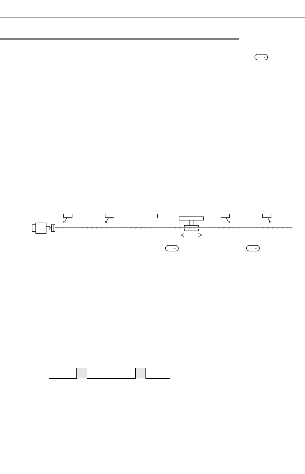
FX
3G
/FX
3U
/FX
3UC
PLC User's Manual - Positioning Control Edition
Built-in Positioning Functions
6 Mechanical Zero Return (DSZR/ZRN Instruction)
6.2 DOG Search Zero Return (DSZR Instruction)
B - 98
6.2.4 Important Points
→ For important programming points, refer to Section 4.7.
• If an input (X000 to X017)*1 from the main unit is used for the near-point signal (DOG) , the rear end
of the near-point signal (DOG) will be monitored (detected) at 1ms intervals (interruption).
Under the following condition, however, monitoring (detection) of the near-point signal (DOG) rear end will
be affected by the input time constant or the scan time of the sequence program:
- An input number of X020 or below or other device (auxiliary relay, etc.) is specified.
*1. Specify X000 to X007 for FX3U-16M, FX3UC-16M.
Specify X000 to X007 for FX3G PLC (main unit).
• Properly set the DOG so that the near-point signal (DOG) can be kept at the ON status until the speed is
reduced to the creep speed.
This instruction will start speed reduction at the front end of the DOG, and will stop the operation at the rear
end of the DOG or at detection of the first zero-phase signal after passing the rear end of the DOG.
The current value register will then be cleared (reset to "0").
If the speed is not reduced to the creep speed before detecting the rear end of the DOG, the operation may
not be stopped at the specified position.
• Use the near-point signal (DOG) between the reverse rotation limit 1 (LSR) and the forward rotation limit 1
(LSF).
The intended operation may not be performed if the relationship among the near-point signal (DOG),
reverse rotation limit 1 (LSR) and forward rotation limit 1 (LSF) is not as shown in the figure below.
• The input device specified for the near-point signal or the zero-phase signal cannot be used
for the following items:
- High-speed counter
- Input interruption
- Pulse catch
- SPD instruction
- DVIT instruction*2
- ZRN instruction
*2. Only available for FX3U and FX3UC PLCs.
• Since the zero-phase signal of the servo motor is used, adjust the relation between the rear end of the
DOG and the zero-phase signal as shown in the following figure. If fine adjustment of the origin position is
needed, adjust the position of the near-point signal (DOG).
• The creep speed should be slow enough.
The zero return instruction will not decelerate at the stop point. Therefore, if the creep speed is not slow
enough, the operation may not stop at the specified position due to inertia.
• If an operand is changed during instruction execution, the change will be ignored and the operation will not
be affected. To change the operation, turn off the command contact of the instruction, and then turn it on
again.
• If the instruction activation contact is turned off during the zero return operation, the speed will decelerate
and the operation will stop. In this case, the "Instruction execution complete" flag (M8029) will not be
turned on.
S
1
Reverse rotation limit 2
(Servo amplifier side) Reverse rotation limit 1
(Programmable
controller side)
LSR
Forward rotation limit 2
(Servo amplifier side)
Forward rotation limit 1
(Programmable
controller side)
LSF
Reverse rotation Forward rotation
Servo motor
DOG
S
1
S
2
DOG
Rear end
Zero-phase signal

FX
3G
/FX
3U
/FX
3UC
PLC User's Manual - Positioning Control Edition
Built-in Positioning Functions
6 Mechanical Zero Return (DSZR/ZRN Instruction)
6.2 DOG Search Zero Return (DSZR Instruction)
B - 99
A
Common Items
B
Built-in
Positioning
Functions
Apx.
Example
Connection
• If the "pulse output monitor" (BUSY/READY) flag is on, a positioning instruction (including PLSR and
PLSY) that uses the same output cannot be executed.
If the "pulse output monitor" (BUSY/READY) flag is still on after the instruction activation contact is turned
off, do not execute a positioning instruction (including PLSR and PLSY instructions) that uses the same
output number.
• In the following case, the "Instruction execution abnormal end" flag (M8329) will be turned on, and the
execution of the instruction will be completed.
→ For details on the "Instruction execution abnormal end" flag, refer to Subsection 4.7.4.
- If the DOG search function cannot detect the near-point signal (DOG), the speed will decelerate and the
operation will stop.
In this case, "Instruction execution abnormal end" flag (M8329) will be turned on, and the execution of
the instruction will be completed.
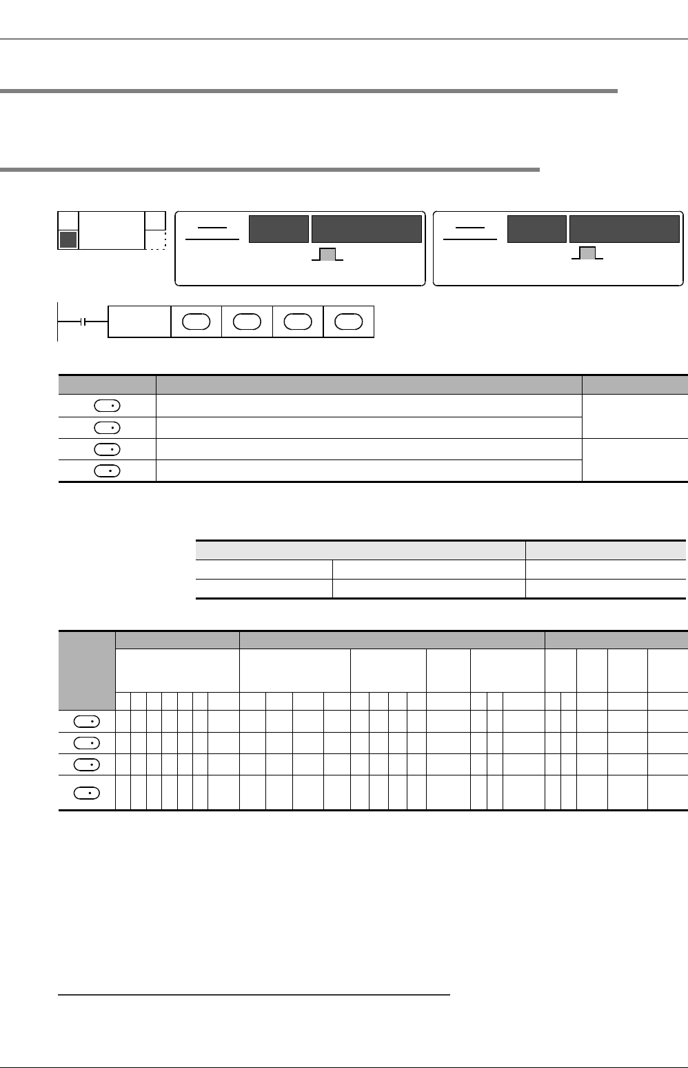
FX
3G
/FX
3U
/FX
3UC
PLC User's Manual - Positioning Control Edition
Built-in Positioning Functions
6 Mechanical Zero Return (DSZR/ZRN Instruction)
6.3 Zero Return (ZRN Instruction)
B - 100
6.3 Zero Return (ZRN Instruction)
Use this instruction to change the CLEAR signal output destination with an FX3U/FX3UC PLC Ver.2.20 or later
or an FX3G PLC.
6.3.1 Instruction Format
1. Instruction Format
2. Data setting
*1. Setting range : 10 to 32,767 Hz for 16-bit operation
For 32-bit operation, however, the setting range should be as shown in the following
table.
3. Devices
1:D.b is available only in FX3U and FX3UC PLCs. However, index modifiers (V and Z) are not available.
2 : Specify Y000, Y001, or Y002*1 transistor output from the main unit, or specify Y000, Y001, Y002*3, or
Y003*3 from a high-speed output special adapter*2.
*1. Y002 is not available in 14-point and 24-point type FX3G PLC.
*2. High-speed input/output special adapters can be connected only to the FX3U PLC.
*3. To use Y002 and Y003 of a high-speed output special adapter, connect a second high-speed output
special adapter.
3 : Only available for FX3U and FX3UC PLCs.
Note:
• To use an FX3U Series main unit of relay output type, be sure to connect a high-speed output special
adapter. Differential line drive type outputs will be used for the outputs of the high-speed output special
adapter.
Operand type Description Data type
Specifies the zero return speed.*1
BIN16/32-bit
Specifies the creep speed. (Setting range: 10 to 32,767 Hz)
Specifies an input number for the near-point signal(DOG). Bit
Specifies the pulse output number.
Pulse output destination Setting range
FX3U PLC High-speed output special adapter 10 to 200,000(Hz)
FX3G/FX3U/FX3UC PLC Main unit (transistor output) 10 to 100,000(Hz)
Operand
type
Bit device Word device Others
System user Digit designation System user Special
unit Index Con-
stant
Real
num-
ber
Char-
acter
string
Pointer
XYMTCSD
.b KnX KnY KnM KnS T C D R U\GV Z Modify K H E ""P
3 3 3 3 3333 333 3 33
3 3 3 3 3333 333 3 33
333 3 13
23
FNC 156
ZRN
ZERO RETURN
D
16-bit
instruction
9 steps ZRN
-
Continuous
execution
type
Instruction
symbol Execution condition 32-bit
instruction Instruction
symbol Execution condition
DZRN
-
Continuous
execution
type
17 steps
Command
input
FNC156
ZRN S
1
•
S
2
•
S
3
•
D
•
S
1
S
2
S
3
D
S
1
S
2
S
3
D

FX
3G
/FX
3U
/FX
3UC
PLC User's Manual - Positioning Control Edition
Built-in Positioning Functions
6 Mechanical Zero Return (DSZR/ZRN Instruction)
6.3 Zero Return (ZRN Instruction)
B - 101
A
Common Items
B
Built-in
Positioning
Functions
Apx.
Example
Connection
6.3.2 List of Related devices
1. Special auxiliary relays
The following table shows the related special auxiliary relays. Note that Y000, Y001, Y002, and Y003 are
devices that determine the pulse output destinations.
*1. Y002 is not available in 14-point and 24-point type FX
3G
PLC.
*2. Devices related to Y003 (pulse output destination) are only valid if two FX
3U
-2HSY-ADP adapters are connected to the FX
3U
PLC.
*3. Cleared when PLC switches from RUN to STOP.
*4. Only available for
FX
3U
/
FX
3UC
PLC Ver. 2.20 or later and
FX
3G
PLC.
2. Special data registers
The following table shows the related special data registers. Note that Y000, Y001, Y002, and Y003 are
devices that determine the pulse output destinations.
*1. Y002 is not available in 14-point and 24-point type FX3G PLC.
*2. Devices related to Y003 (pulse output destination) are
only valid
if two FX3U-2HSY-ADP adapters are connected to the
FX3U PLC.
*3. Only available for FX3U/FX3UC PLC Ver. 2.20 or later and FX3G PLC.
Device number Function Attribute Refer to
Y000 Y001 Y002*1 Y003*2
M8029 "Instruction execution complete" flag Read only Subsection
4.4.2
M8329 "Instruction execution abnormal end" flag Read only Subsection
4.4.2
M8340 M8350 M8360 M8370 "Pulse output monitor" (BUSY/READY) flag Read only Subsection
4.4.3
M8341 M8351 M8361 M8371 CLEAR signal output function enable*3 Drivable Subsection
4.3.4
M8343 M8353 M8363 M8373 Forward limit Drivable Subsection
4.3.1
M8344 M8354 M8364 M8374 Reverse limit Drivable Subsection
4.3.1
M8348 M8358 M8368 M8378 Positioning instruction activation Read only Subsection
4.4.4
M8349 M8359 M8369 M8379 Pulse output stop command*3 Drivable Subsection
4.3.2
M8464 M8465 M8466 M8467 CLEAR signal device specification function
enable*3, *4 Drivable Subsection
4.3.4
Device number Function Data
length
Initial
value Refer to
Y000 Y001 Y002*1 Y003*2
D8340 Low-
order D8350 Low-
order D8360 Low-
order D8370 Low-
order Current value
register (PLS) 32-bit 0 Subsection
4.4.1
D8341 High-
order D8351 High-
order D8361 High-
order D8371 High-
order
D8342 D8352 D8362 D8372 Bias speed
(Hz) 16-bit 0 Subsection
4.2.6
D8343 Low-
order D8353 Low-
order D8363 Low-
order D8373 Low-
order Maximum
speed (Hz) 32-bit 100,000 Subsection
4.2.5
D8344 High-
order D8354 High-
order D8364 High-
order D8374 High-
order
D8348 D8358 D8368 D8378 Acceleration
time (ms) 16-bit 100 Subsection
4.2.7
D8349 D8359 D8369 D8379 Deceleration
time (ms) 16-bit 100 Subsection
4.2.8
D8464 D8465 D8466 D8467
CLEAR signal
device
specification*3
16-bit - Subsection
4.3.4
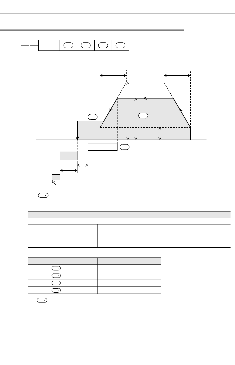
FX
3G
/FX
3U
/FX
3UC
PLC User's Manual - Positioning Control Edition
Built-in Positioning Functions
6 Mechanical Zero Return (DSZR/ZRN Instruction)
6.3 Zero Return (ZRN Instruction)
B - 102
6.3.3 Function and operation
→ For details on the maximum speed, bias speed, acceleration time and deceleration time, refer to
Subsection 4.2.5 to Subsection 4.2.8.
1) For , specify the zero return speed.
If the set zero return speed value is more than the maximum speed value, the operation will be performed
at the maximum speed.
Note that the zero return speeds shown in the following table will not apply.
2) For , specify the creep speed.
Setting range: 10 to 32,767 Hz
Setting range
16-bit operation 10 to 32,767(Hz)
32-bit operation
When a high-speed output special
adapter is used 10 to 200,000(Hz)
When a transistor output from the
main unit is used 10 to 100,000(Hz)
Pulse output destination device Zero return speed
= Y000 D8347,D8346
= Y001 D8357,D8356
= Y002 D8367,D8366
= Y003 D8377,D8376
Command
input
FNC156
ZRN S
1
•
S
2
•
S
3
•
D
•
Maximum speed
Zero return speed
Deceleration
time
Bias speed
Acceleration
time
DOG
Creep speed
CLEAR signal Front endRear end
1 ms or less
20 ms + 1 scan time (ms)
S
3
•
S
2
•
ON
"Instruction
execution
complete" flag
M8029
When the instruction is turned off, M8029 is turned off.
S
1
•
S
1
D
1
D
1
D
1
D
1
S
2
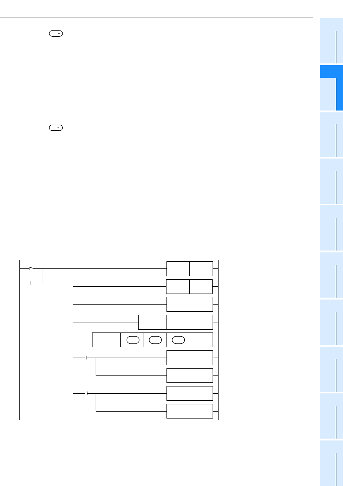
FX
3G
/FX
3U
/FX
3UC
PLC User's Manual - Positioning Control Edition
Built-in Positioning Functions
6 Mechanical Zero Return (DSZR/ZRN Instruction)
6.3 Zero Return (ZRN Instruction)
B - 103
A
Common Items
B
Built-in
Positioning
Functions
Apx.
Example
Connection
3) For , specify the near-point signal (DOG) input device number ( NO contact).
Turning on the near-point signal will reduce the speed to the creep speed. Turning off the near-point
signal will complete the zero return operation.
→ For details, refer to "1. Zero return operation".
• If an input (X000 to X007) of the main unit is specified for the input signal, the PLC interruption function
will be used to stop the operation. (To output the CLEAR signal, turn on the "CLEAR signal output
function enable" relay.)
Under the following condition, however, operation may be affected by the input constant or the scan
time of the sequence program, and the operation, therefore, may not be stopped exactly at the origin.
-An input number of X010 or below (or other device (auxiliary relay, etc.)) is specified.
• If an input relay X010 or higher is specified for the near-point signal, the input filter (10 ms) will be
applied.
4) For , specify a pulse output number in the range of Y000 to Y003.
5) Zero return direction
For this instruction, the zero return direction is set to the reverse rotation direction.
(During zero return operation, the value indicated in the current value register will be decreased.)
To perform zero return in the forward rotation direction*1, follow the example program below to control the
direction output.
→ For programming details, refer to Section 4.7.
→ To use the main unit (transistor output), refer to Section 4.8.
→ To use a high-speed output special adapter, refer to Section 4.9.
a) Turn on Y (rotational direction signal).
b) Refresh Y output using the REF (FNC50) instruction.
c) Execute the ZRN instruction (zero return instruction).
d) With the execution completion flag (M8029) of the ZRN instruction (zero return instruction), reset
Y (rotational direction signal).
Example program:
In the program shown below, Y004 is specified as the rotation direction signal output device for Y000.
*1. The pulses being output will always decrease the current value.
S
3
D
C
omman
d
input
Turns on (sets) Y004 as the
rotational direction signal of Y000
(pulse output destination).
M8340
Y000 output
pulse monitor
K8Y000
Y000
Y004RST
Refreshes Y000 to Y007.
Executes ZRN instruction.
Resets the rotational direction
signal (Y004) using the instruction
execution complete flag.
Y004SET
FNC 50
REFP
FNC156
DZRN S
1
•
S
2
•
S
3
•
M8029
M11RST
M10RST
M10SET Origin data reading completion flag
Resets the rotational direction signal
(Y004) using the instruction
execution abnormal end flag.
Y004RST
M8329
M11SET Abnormal end of zero return
a)
b)
c)
d)
FX
3G
/FX
3U
/FX
3UC
PLC User's Manual - Positioning Control Edition
Built-in Positioning Functions
6 Mechanical Zero Return (DSZR/ZRN Instruction)
6.3 Zero Return (ZRN Instruction)
B - 104
6) CLEAR signal output
This instruction can output the CLEAR signal after stopping at the origin. If it is necessary to output the
CLEAR signal at the completion of zero return, turn on the "CLEAR signal output function enable" relay
(see the following table). Use an FX3U/FX3UC PLC Ver.2.20 or later or FX3G PLC to specify the CLEAR
signal output device.
a) If it is not necessary to use the CLEAR signal device specification function, or if an FX3UC PLC of
below Ver.2.20 is used:
*1. Use an FX3U/FX3UC PLC Ver.2.20 or later or FX3G PLC to use the "CLEAR signal device specification function
enable" relay.
b) If it is necessary to use the CLEAR signal device specification
function:
Turn on the "CLEAR signal device specification function enable"
relay to specify the CLEAR signal output device (output Y) for the
pulse output destination device using the CLEAR signal device specification register.
→ For the example of a program, refer to Subsection 4.3.4 or Subsection 4.5.1.
Pulse output
destination device
Status of "CLEAR
signal output function
enable" relay
Status of "CLEAR signal
device specification
function enable" relay*1
CLEAR signal device
number
= Y000 M8341=ON M8464=OFF Y004
= Y001 M8351=ON M8465=OFF Y005
= Y002 M8361=ON M8466=OFF Y006
= Y003 M8371=ON M8467=OFF Y007
Pulse output
destination device
Status of "CLEAR
signal output function
enable" relay
Status of "CLEAR signal
device specification
function enable" relay
CLEAR signal device
specification register
= Y000 M8341=ON M8464=ON D 8464
= Y001 M8351=ON M8465=ON D 8465
= Y002 M8361=ON M8466=ON D 8466
= Y003 M8371=ON M8467=ON D 8467
D
1
D
1
D
1
D
1
D
1
D
1
D
1
D
1
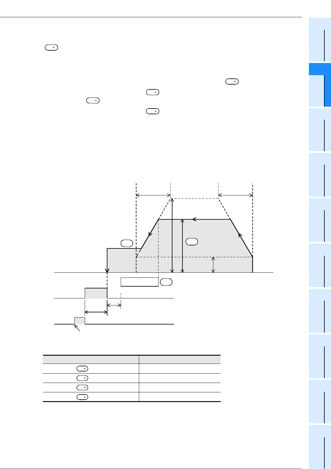
FX
3G
/FX
3U
/FX
3UC
PLC User's Manual - Positioning Control Edition
Built-in Positioning Functions
6 Mechanical Zero Return (DSZR/ZRN Instruction)
6.3 Zero Return (ZRN Instruction)
B - 105
A
Common Items
B
Built-in
Positioning
Functions
Apx.
Example
Connection
1. Zero return operation
Zero return operation is described below assuming that Y000 is specified as the pulse output destination
device . If Y001, Y002, and Y003 are specified, it is necessary to change the output number of each
related relay (special auxiliary relay, special data register) below.
→ For details on related flags, refer to Section 4.1 to Section 4.4, or Subsection 6.2.2.
1) Execute the ZRN instruction to carry out zero return.
2) Transfer operation will be performed at the zero return speed specified by .
3) If the near-point signal (DOG) specified by is turned on, the speed will be reduced to the creep
speed specified by .
4) If the near-point signal (DOG) specified by is turned off, the pulse outputting operation will be
immediately stopped.
5) If the CLEAR signal output function (M8341) is enabled (set to ON), the CLEAR signal (Y004) will be
turned on within 1 ms after stopping the pulse outputting operation, and will be kept ON for "20 ms + 1
scan time (ms)".
6) The current value register (D8341, D8340) will be reset to "0" (will be cleared).
7) "Instruction execution complete" flag will be turned on, and the zero return operation will be completed.
→ For details on "Instruction execution complete" flag, refer to Subsection 4.7.4.
*1. Note that the zero return speeds shown in the following table will not apply.
Pulse output destination device Zero return speed
= Y000 D8347,D8346
= Y001 D8357,D8356
= Y002 D8367,D8366
= Y003 D8377,D8376
D
S
1
S
3
S
2
S
3
Maximum speed
(D8344,D8343)
Zero return speed
*1
Deceleration
time
(D8349)
Bias speed
(D8342)
Acceleration
time
(D8348)
DOG
Creep speed
CLEAR signal
Y004
Front endRear end
1 ms or less
20 ms + 1scan time (ms)
S
2
•
ON
"Instruction
execution
complete" flag
M8029
When the instruction is turned off, M8029 is turned off.
S
1
•
S
3
•
D
1
D
1
D
1
D
1

FX
3G
/FX
3U
/FX
3UC
PLC User's Manual - Positioning Control Edition
Built-in Positioning Functions
6 Mechanical Zero Return (DSZR/ZRN Instruction)
6.3 Zero Return (ZRN Instruction)
B - 106
6.3.4 Important Points
→ For important programming points, refer to Section 4.7.
• If an input (X000 to X007) of the main unit is specified for the near-point input signal specified by , the
PLC interruption function will be used to stop the operation.
Under the following condition, however, operation may be affected by the input constant or the scan time of
the sequence program.
- An input number of X010 or below (or other device (auxiliary relay, etc.)) is specified.
If input relay X010 or higher is specified for the near-point signal, the input filter (10 ms) will be applied.
• If an input (X000 to X007) is specified for the near-point signal , the input cannot be used for the
following items:
- High-speed counter
- Input interruption
- Pulse catch
- SPD instruction
- DSZR instruction
- DVIT instruction*1
• Properly set the DOG so that the near-point signal (DOG) can be kept ON until the speed is reduced to the
creep speed.
This instruction will start speed reduction at the front end of the DOG, and will stop the operation at the rear
end of the DOG. The current value register will then be cleared (reset to "0").
If the speed is not reduced to the creep speed before detecting the rear end of the DOG, the operation may
not be stopped at the specified position.
• The creep speed should be slow enough.
The zero return instruction will not decelerate at the stop point. Therefore, if the creep speed is not slow
enough, the operation may not stop at the specified position due to inertia.
• The DOG search function does not apply for this instruction. Therefore, start the zero return operation on
the front side of the near-point signal. If it is necessary to use the DOG search function, use the DSZR
instruction.
• The zero-phase signal of the servo motor cannot be used. For this reason, if fine adjustment of the origin
position is needed, adjust the position of the near-point signal (DOG).
• If the instruction activation contact is turned off during zero return operation, the speed will decelerate and
the operation will stop. In this case, the "Instruction execution complete" flag (M8029) will not turn on.
• While the "pulse output monitor" (BUSY/READY) flag is on, a positioning instruction (including PLSR and
PLSY) that uses the same output cannot be executed.
If the "pulse output monitor" (BUSY/READY) flag is still on after the instruction activation contact is turned
off, do not execute a positioning instruction (including PLSR and PLSY instructions) that uses the same
output number.
• In the following case, the "Instruction execution abnormal end" flag (M8329) will be turned on, and
execution of the instruction will be completed.
→ For details on the "Instruction execution abnormal end" flag, refer to Subsection 4.7.4.
- If the forward limit relay or the reverse limit relay is turned on, the speed will decelerate and the
operation will stop. In this case, the "Instruction execution abnormal end" flag (M8329) will be turned on
when execution of the instruction is complete.
- If the limit relay (forward limit relay or reverse limit relay) on the opposite side of the operation direction
is turned on, the speed will decelerate and the operation will stop.
In this case, the "Instruction execution abnormal end" flag (M8329) will be turned on when execution of
the instruction is complete.
*1. Only available for
FX
3U
and
FX
3UC
PLCs.
S
3
S
3
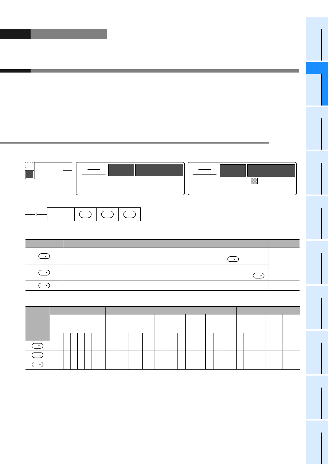
7 Absolute Position Detection System (Absolute Current Value Read)-ABS
7.1 Instruction Format
B - 107
FX
3G
/FX
3U
/FX
3UC
PLC User's Manual - Positioning Control Edition
Built-in Positioning Functions
A
Common Items
B
Built-in
Positioning
Functions
Apx.
Example
Connection
7. Absolute Position Detection System
(Absolute Current Value Read)-ABS Instruction
With the use of the servo absolute position detection system, the built-in positioning function uses the current
ABS value read-out (ABS) instruction to read out the current value (absolute position (ABS) data) from the
MELSERVO-H, -J2(S), or -J3 servo amplifier.
→ For items to be observed in programming, refer to Section 4.7.
→ For the servo amplifier and connection of the MELSERVO Series, refer to the Appendix and the
examples of connection.
7.1 Instruction Format
1. Instruction Format
2. Data setting
3. Devices
1 : D.b is available only in FX3U and FX3UC PLCs. However, index modifiers (V and Z) are not available.
2 : Only available for to FX3U and FX3UC PLCs.
Operand type Description Data type
Specifies the first number of the device that inputs the absolute position (ABS) data
from the servo amplifier. Number of occupied points: 3 (first point for ) BIN16-bit
Specifies the first number of the device that outputs the absolute position (ABS) data
control signal to the servo amplifier. Number of occupied points: 3 (first point for )
Specifies the absolute position (ABS) data (32-bit value) storage device number. BIN32-bit
Operand
type
Bit device Word device Others
System user Digit designation System user Special
unit Index Con-
stant
Real
num-
ber
Char-
acter
string
Pointer
XYMTCSD.b KnX KnY KnM KnS T C D R U/GVZ
Modify
KH E ""P
333 3 13
33 3 13
3 3 3 3333 233 3
FNC 155
ABS
ABSOLUTE
D
DABS
−
32-bit
instruction Instruction
symbol Execution condition
13 steps Continuous
execution
type
−
−
16-bit
instruction Instruction
symbol Execution condition
Command
input
FNC 155
DABS S
•
D
1
•
D
2
•
S
S
D
1
D
1
D
2
S
D
1
D
2
FX
3G
/FX
3U
/FX
3UC
PLC User's Manual - Positioning Control Edition
Built-in Positioning Functions
7 Absolute Position Detection System (Absolute Current Value Read)-ABS Instruction
7.2 List of Related Devices
B - 108
7.2 List of Related Devices
→ For details on the related devices, refer to Section 4.1 to Section 4.4.
1. Special auxiliary relays
The following table shows the related special auxiliary relays.
Note that Y000, Y001, Y002, and Y003 are devices that determine the pulse output destinations.
→ For details on PLSY (FNC57), PWM (FNC58), and PLSR (FNC59) instructions, refer to the
programming manual.
*1. Y002 is not available in 14-point and 24-point type FX3G PLC.
*2. Devices related to Y003 (pulse output destination) are only valid if two FX3U-2HSY-ADP adapters are
connected to the FX3U PLC.
2. Special data registers
The following table shows the related special data registers. Note that Y000, Y001, Y002, and Y003 are
devices that determine the pulse output destinations.
*1. Y002 is not available in 14-point and 24-point type FX3G PLC.
*2. Devices related to Y003 (pulse output destination) are only valid if two FX3U-2HSY-ADP adapters are
connected to the FX3U PLC.
7.3 Function and Operation
Connect an MR-H, MR-J2(S), or MR-J3 servo motor (with absolute position detection function) manufactured
by Mitsubishi to your system, and use this instruction to read out the absolute position (ABS) data. The data
will be converted into a pulse value before being read out.
1) For , specify the first number of the device that inputs the absolute position (ABS) data from the
servo amplifier. Number of occupied points: 3 ( , +1, +2)
2) For , specify the first number of the device that outputs the absolute position (ABS) data control
signal to the servo amplifier. Be sure to use transistor outputs for the PLC outputs.
Number of occupied points: 3 ( , +1, +2)
3) For , specify the absolute position (ABS) data (32-bit value) storage device number to store the
data read out from the servo amplifier. Handle the absolute position (ABS) data as follows:
- To use the built-in pulse output function, be sure to specify the following current value registers for the
read-out ABS data:
*1. Y002 is not available in 14-point and 24-point type FX3G PLC.
*2. Devices related to Y003 (pulse output destination) are only valid if two FX3U-2HSY-ADP adapters are
connected to the FX3U PLC.
Device number Function Attribute Refer to
Y000 Y001 Y002*1 Y003*2
M8029 "Instruction execution complete" flag Read only Subsection
4.4.2
M8329 "Instruction execution abnormal end" flag Read only Subsection
4.4.2
Device number Function Data
length
Initial
value Refer to
Y000 Y001 Y002*1 Y003*2
D8340 Low-
order D8350 Low-
order D8360 Low-
order D8370 Low-
order
Current
value
register
(PLS)
32-bit 0 Subsection
4.4.1
D8341 High-
order D8351 High-
order D8361 High-
order D8371 High-
order
Y000 Y001 Y002*1 Y003*2
D8341,D8340 D8351,D8350 D8361,D8360 D8371, D8370
Command
input
FNC 155
DABS S
•
D
1
•
D
2
•
S
S
S
S
D
1
D
1
D
1
D
1
D
2
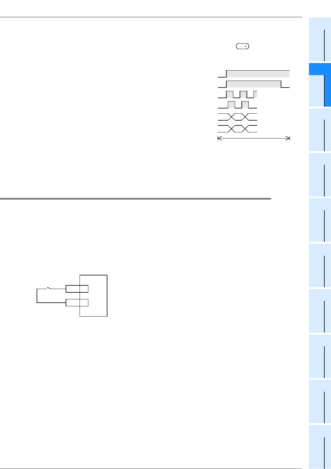
7 Absolute Position Detection System (Absolute Current Value Read)-ABS
7.4 Initial Zero Return
B - 109
FX
3G
/FX
3U
/FX
3UC
PLC User's Manual - Positioning Control Edition
Built-in Positioning Functions
A
Common Items
B
Built-in
Positioning
Functions
Apx.
Example
Connection
- When using the FX2N-1PG(-E) or FX2N-10PG, read out the ABS data from the data register first, and
then write the read-out ABS data into the current value register of the FX2N-1PG(-E) or FX2N-10PG
using the DTO instruction or directly specify the buffer memory (U\G) for to be written to.
1. Detection of absolute position
1) If the DABS (FNC155) instruction turns ON, the
PLC will activate the servo-ON output and the
ABS transfer mode output.
2) 32+6-bit data communication will be performed
while mutually checking the data sending/
receiving condition using the "send data ready"
signal and the "ABS data request" signal.
3) The 2-bit line (line for ABS bit 0 and bit 1) will be
used for data transmission.
4) At the completion of ABS data reading, the
"Instruction execution complete" flag (M8029)
will turn on.
→ For details on the "Instruction execution
complete" flag, refer to
Subsection 4.7.4.
7.4 Initial Zero Return
When your system is established, even if your servo motor is equipped with an absolute position detection
function, it is necessary to perform zero return at least once to send the CLEAR signal to the servo motor.
Use one of the following methods for the initial zero return:
1) Execute DSZR (FNC150) with DOG search zero return instruction or ZRN (FNC156) zero return
instruction using the CLEAR signal function to complete zero return.
2) Carry out zero return for the machine using the position adjustment method in the jogging operation mode
or manual operation mode, and then input the CLEAR signal.
To input the CLEAR signal, use the output of the PLC or the external switch shown in the following figure.
D
2
Servo-ON SON
ABS data transfer
mode ABSM
TLC
ABSR
ZSP
DO1
"Send data ready"
signal
"ABS data request"
signal
ABS(bit 1)
ABS(bit 0)
Current position data (32 bits)
+ check data (6 bits)
Amplifier output
PLC output
Amplifier output
Amplifier output
CR 8
SG 10
Example for MR-J2-
A
CLEAR
signal

FX
3G
/FX
3U
/FX
3UC
PLC User's Manual - Positioning Control Edition
Built-in Positioning Functions
7 Absolute Position Detection System (Absolute Current Value Read)-ABS Instruction
7.5 Important Points
B - 110
7.5 Important Points
• Set the timing sequence for powering on your system so that the power of the PLC is turned on after the
power of the servo amplifier, or that power is turned on at the same time.
• Leave the drive contact of the DABS (FNC155) instruction ON after reading the ABS value. If the
instruction activation contact is turned off at the completion of ABS data reading, the servo-ON (SON)
signal will be turned off, and the operation will not be performed.
• If the instruction activation contact is turned off during data reading, data reading will be stopped.
• This instruction is for 32-bit data only. Be sure to input this instruction as the DABS instruction.
• Observe the following items to use the FX2N-1PG(-E) or FX2N-10PG:
- ABS data will be converted into a pulse value before being read out. For this reason, be sure to specify
"motor system" when setting the parameters (BFM #3) for the FX2N-1PG(-E).
- When writing ABS data to the FX2N-10PG, be sure to use the current value register (BFM #40, BFM
#39) to store the converted pulse data.
• Even if data-communication with the servo amplifier is not performed properly, no error will be detected.
For this reason, it is necessary to monitor the handshaking operation using the time-out error detection
timer.
→ For the example programs, refer to Section 12.5.
• Set the servo motor rotation direction as described below when using the ABS instruction. Note that the
sign (plus or minus) may be different between the current value controlled by the PLC and the current
value existing in the servo amplifier after the current value is read by the ABS instruction if another
direction is set.In the MR-J2--A and MR-H--A, the setting "Forward rotation (CCW) when forward
rotation pulses are input, and reverse rotation (CW) when reverse rotation pulses are input" cannot be
changed.
- When using the positioning function built in the FX3G, FX3U and FX3UC PLC
Set the servo amplifier rotation direction to "Forward rotation (CCW) when forward rotation pulses are
input, and reverse rotation (CW) when reverse rotation pulses are input".
→ For details, refer to the Servo amplifier manual.
- When using the FX2N-1PT or FX2N-10PG with the FX3U or FX3UC PLC
Achieve the following relationship for the rotation direction setting between the FX2N-1PG or FX2N-
10PG and the servo amplifier.
Setting in FX2N-1PG(-E)/FX2N-10PG Setting in servo amplifier
Current value is increased by forward
rotation pulses.
Servo amplifier rotates forward (CCW) when forward
rotation pulses are input.
Servo amplifier rotates backward (CW) when
reverse rotation pulses are input.
Current value is decreased by forward
rotation pulses.
Servo amplifier rotates forward (CW) when forward
rotation pulses are input.
Servo amplifier rotates backward (CCW) when
reverse rotation pulses are input.
FX
3G
/FX
3U
/FX
3UC
PLC User's Manual - Positioning Control Edition
Built-in Positioning Functions
8 1-Speed Positioning - DRVI/DRVA Instruction
8.1 Incremental Method and Absolute Method
B - 111
A
Common Items
B
Built-in
Positioning
Functions
Apx.
Example
Connection
8. 1-Speed Positioning - DRVI/DRVA Instruction
The built-in positioning function uses the drive to increment (DRVI) instruction or the drive to absolute (DRVA)
instruction to perform 1-speed positioning. Note that these two instructions use different target position
setting methods.
→ For important items common to all of the positioning instructions, refer to Section 4.7.
→ For example programs, refer to Chapter 12.
8.1 Incremental Method and Absolute Method
There are two target position setting methods for positioning operations as described below:
1. Incremental method (relative address setting method)
While regarding the current position as the start point, specify the transfer direction and the transfer distance
(relative address) to determine the target position.
Instruction Target position setting method
Drive to Increment (DRVI) instruction Incremental method:
Uses a relative address to specify the target position.
Drive to Absolute (DRVA) instrument Absolute method:
Uses an absolute address to specify the target position.
150
Point B
Transfer distance: -100
300
Point C
100
Point A
0
Origin
Start point
End point
To Ueno
Current position Target position
To go from Odawara (current position) to Atami (target position), set the distance (+20.7 km)
from Odawara to Atami.
Transfer distance: +50
Transfer distance: -150
Transfer distance: +100
Transfer distance: +100
Transfer
distance:
+100
Transfer distance:
-100
+20.7km-20.7km Relative address
For example:
ShizuokaMishimaAtamiOdawaraShinyokohamaTokyo
FX
3G
/FX
3U
/FX
3UC
PLC User's Manual - Positioning Control Edition
Built-in Positioning Functions
8 1-Speed Positioning - DRVI/DRVA Instruction
8.1 Incremental Method and Absolute Method
B - 112
2. Absolute method (absolute address setting method)
Specify the distance (absolute address) from the origin to the target position. In this case, any position can be
the start point (current position).
Address
100
Address
150
Address
100
Address 150
Address 150
Address 100
Address
300
300
Point C
150
Point B
100
Point A
0
Origin
Start point
End point
ShizuokaMishimaAtamiOdawaraShinyokohamaTokyo
Origin
To Ueno
Absolute address 0 28.8km
Current position
83.9km
→
104.6km 120.7km 180.2km
Target position
To go from Odawara (current position) to Atami (target position), set the distance (+104.6 km)
from Tokyo (origin) to Atami.
For example:
→→→→
FX
3G
/FX
3U
/FX
3UC
PLC User's Manual - Positioning Control Edition
Built-in Positioning Functions
8 1-Speed Positioning - DRVI/DRVA Instruction
8.2 Drive to Increment - DRVI Instruction
B - 113
A
Common Items
B
Built-in
Positioning
Functions
Apx.
Example
Connection
8.2 Drive to Increment - DRVI Instruction
8.2.1 Instruction Format
1. Instruction Format
2. Data setting
*1. Setting range : -32,768 to +32,767 (excluding 0) for 16-bit operation
: -999,999 to +999,999 (excluding 0) for 32-bit operation
*2. Setting range : 10 to 32,767 Hz for 16-bit operation
For 32-bit operation, however, the setting range is as shown in the following table.
3. Devices
1 : Specify Y000, Y001, or Y002*1 transistor output from the main unit, or specify Y000, Y001, Y002*3, or
Y003*3 from a high-speed output special adapter*2.
*1. Y002 is not available in 14-point and 24-point type FX3G PLC.
*2. High-speed input/output special adapters can be connected only to the FX3U PLC.
*3. To use Y002 and Y003 with a high-speed output special adapter, connect a second high-speed output
special adapter.
Note:
• To use an FX3U Series main unit of relay output type, be sure to connect a high-speed output special
adapter. Differential line drive type outputs will be used for the outputs of the high-speed output special
adapter.
Operand type Description Data type
Specifies the number of output pulses (relative address).*1
BIN16/32-bit
Specifies the output pulse frequency.*2
Specifies the pulse output number. Bit
Specifies the rotation direction signal output destination device number.
Pulse output destination Setting range
FX3U PLC High-speed output special adapter 10 to 200,000(Hz)
FX3G/FX3U/FX3UC PLC Main unit (transistor output) 10 to 100,000(Hz)
Operand
type
Bit device Word device Others
System user Digit designation System
user
Special
unit Index Con-
stant
Real
num-
ber
Char
acter
string
Pointer
XYMTCSD.b KnX KnY KnM KnS T C D R U\GV Z Modify K H E ""P
3 3 3 3 3333 433 3 3 3
3 3 3 3 3333 433 3 3 3
13
23333
FNC 158
DRVI
DRIVE TO
INCREMENT
D
16-bit
instruction
9 steps DRVI
-
Continuous
execution
type
Instruction
symbol Execution condition 32-bit
instruction Instruction
symbol Execution condition
DDRVI
-
Continuous
execution
type
17 steps
Command
input
FNC 158
DRVI S
1
•
S
2
•
D
1
•
D
2
•
S
1
S
2
D
1
D
2
S
1
S
2
D
1
D
2
FX
3G
/FX
3U
/FX
3UC
PLC User's Manual - Positioning Control Edition
Built-in Positioning Functions
8 1-Speed Positioning - DRVI/DRVA Instruction
8.2 Drive to Increment - DRVI Instruction
B - 114
2 : When a high-speed output special adapter is used as a destination for pulse output on a FX3U PLC,
use the output shown in the following table for rotation direction signals.
When a built-in transistor output is used as a destination for pulse output on a FX3G/FX3U/FX3UC PLC,
use transistor output for signals rotation direction.
→ For the outputs applicable with a High-speed output special adapter, refer to Section 4.9.
3 : D.b is available only in FX3U and FX3UC PLCs. However, index modifiers (V and Z) are not available.
4 : Only available for FX3U and FX3UC PLCs.
8.2.2 List of Related Devices
1. Special auxiliary relays
The following table shows the related special auxiliary relays. Note that Y000, Y001, Y002, and Y003 are
devices that determine the pulse output destinations.
High-speed output special
adapter connection position Pulse output Rotation direction output
1st adapter = Y000 = Y004
= Y001 = Y005
2nd adapter = Y002 = Y006
= Y003 = Y007
Device number Function Attribute Refer to
Y000 Y001 Y002*1 Y003*2
M8029 "Instruction execution complete" flag Read only Subsection
4.4.2
M8329 "Instruction execution abnormal end" flag Read only Subsection
4.4.2
M8340 M8350 M8360 M8370 "Pulse output monitor" (BUSY/READY) flag Read only Subsection
4.4.3
M8343 M8353 M8363 M8373 Forward limit Drivable Subsection
4.3.1
M8344 M8354 M8364 M8374 Reverse limit Drivable Subsection
4.3.1
M8348 M8358 M8368 M8378 Positioning instruction activation Read only Subsection
4.4.4
M8349 M8359 M8369 M8379 Pulse output stop command*3 Drivable Subsection
4.3.2
*1. Y002 is not available in 14-point and 24-point type FX3G PLC.
*2. Devices related to Y003 (pulse output destination) are only valid if two FX3U-2HSY-ADP adapters are
connected to the FX3U PLC.
*3. Cleared when the PLC switches from RUN to STOP.
D
1
D
2
D
1
D
2
D
1
D
2
D
1
D
2

FX
3G
/FX
3U
/FX
3UC
PLC User's Manual - Positioning Control Edition
Built-in Positioning Functions
8 1-Speed Positioning - DRVI/DRVA Instruction
8.2 Drive to Increment - DRVI Instruction
B - 115
A
Common Items
B
Built-in
Positioning
Functions
Apx.
Example
Connection
2. Special data registers
The following table shows the related special data registers. Note that Y000, Y001, Y002, and Y003 are
devices that determine the pulse output destinations.
*1. Y002 is not available in 14-point and 24-point type FX3G PLC.
*2. Devices related to Y003 (pulse output destination) are only valid if two FX3U-2HSY-ADP adapters are
connected to the FX3U PLC.
Device number Function Data
length
Initial
value Refer to
Y000 Y001 Y002*1 Y003*2
D8340 Low-
order D8350 Low-
order D8360 Low-
order D8370 Low-
order Current value register
(PLS) 32-bit 0 Subsection
4.4.1
D8341 High-
order D8351 High-
order D8361 High-
order D8371 High-
order
D8342 D8352 D8362 D8372 Bias speed (Hz) 16-bit 0 Subsection
4.2.6
D8343 Low-
order D8353 Low-
order D8363 Low-
order D8373 Low-
order Maximum speed (Hz) 32-bit 100,000 Subsection
4.2.5
D8344 High-
order D8354 High-
order D8364 High-
order D8374 High-
order
D8345 D8355 D8365 D8375 Creep speed (Hz) 16-bit 1000 Subsection
4.2.4
D8346 Low-
order D8356 Low-
order D8366 Low-
order D8376 Low-
order Zero return speed (Hz) 32-bit 50,000 Subsection
4.2.3
D8347 High-
order D8357 High-
order D8367 High-
order D8377 High-
order
D8348 D8358 D8368 D8378 Acceleration time (ms) 16-bit 100 Subsection
4.2.7
D8349 D8359 D8369 D8379 Deceleration time (ms) 16-bit 100 Subsection
4.2.8
FX
3G
/FX
3U
/FX
3UC
PLC User's Manual - Positioning Control Edition
Built-in Positioning Functions
8 1-Speed Positioning - DRVI/DRVA Instruction
8.2 Drive to Increment - DRVI Instruction
B - 116
8.2.3 Function and Operation
This instruction uses a relative drive method to perform a 1-speed positioning instruction. For this instruction,
the transfer distance from the current position to the target position should be specified together with a plus or
minus sign. This method is also referred to as the incremental (relative) drive method.
→ For details on the "Instruction execution complete" flag, refer to Subsection 4.7.4.
→ For details on the maximum speed, bias speed, acceleration time, and deceleration time, refer to
Section 4.2.
1) For , specify the number of output pulses (relative address value).
2) For , specify the output pulse frequency.
3) For , specify the pulse output number in the range of Y000 to Y003.
4) For , specify the rotation direction signal output device number.
When a high-speed output special adapter is used as a destination for pulse output on a FX3U PLC, use
the output shown in the following table for rotation direction signals.
When a built-in transistor output is used as a destination for pulse output on a FX3G/FX3U/FX3UC PLC,
use transistor output for signals rotation direction.
Setting range
16-bit operation -32,768 to +32,767
32-bit operation -999,999 to +999,999
Setting range
16-bit operation 10 to 32,767(Hz)
32-bit operation
When a high-speed output special
adapter is used 10 to 200,000(Hz)
When a transistor output from the
main unit is used 10 to 100,000(Hz)
High-speed output special
adapter connection position
Pulse output
destination device
Rotation direction
output
1st adapter = Y000 = Y004
= Y001 = Y005
2nd adapter = Y002 = Y006
= Y003 = Y007
Command
input
FNC 158
DRVI S
1
•
S
2
•
D
1
•
D
2
•
Output pulse
frequency
Time
Speed
Instruction execution
Number of output
pulses S
1
•
S
2
•
"Instruction
execution complete" flag
M8029 ON
Maximum speed
Deceleration
time
Bias
speed
Acceleration
time
S
1
S
2
D
1
D
2
D
1
D
2
D
1
D
2
D
1
D
2
D
1
D
2

FX
3G
/FX
3U
/FX
3UC
PLC User's Manual - Positioning Control Edition
Built-in Positioning Functions
8 1-Speed Positioning - DRVI/DRVA Instruction
8.2 Drive to Increment - DRVI Instruction
B - 117
A
Common Items
B
Built-in
Positioning
Functions
Apx.
Example
Connection
The rotation direction ON/OFF status of the specified device is shown in the following table.
During instruction execution, however, do not use the output for other purposes.
8.2.4 Important Points
→ For the important points of programming, refer to Section 4.7.
• If an operand is changed during instruction execution, the change will be ignored and the operation will not
be affected.
Note that the changed operand will be enabled at the next activation of the instruction.
• If the instruction activation contact is turned off during execution of the instruction, the speed will
decelerate and the operation will stop.
In this case, the "Instruction execution complete" flag (M8029) will not be turned on.
• If the limit flag (forward limit relay or reverse limit relay) in the operation direction is turned on, the speed
will decelerate and the operation will stop.
In this case, the "Instruction execution abnormal end" flag (M8329) will be turned on when execution of the
instruction is complete.
→ For details on the "Instruction execution abnormal end" flag, refer to Subsection 4.7.4.
• While the "pulse output monitor" (BUSY/READY) flag is on, a positioning instruction (including PLSR and
PLSY) that uses the same output cannot be executed.
If the "pulse output monitor" (BUSY/READY) flag is still on after the instruction activation contact is turned
off, do not execute a positioning instruction (including PLSR and PLSY instructions) that uses the same
output number.
ON/OFF status of device
specified by Rotation direction (increase/decrease current value)
ON
If the number of output pulses specified by is a positive number, the operation will be
performed in the forward rotation direction.
Forward rotation (Outputting pulses from will increase the current value.)
OFF
If the number of output pulses specified by is a negative number, the operation will
be performed in the reverse rotation direction.
Reverse rotation (Outputting pulses from will decrease the current value.)
D
2
D
2
S
1
D
1
S
1
D
1
FX
3G
/FX
3U
/FX
3UC
PLC User's Manual - Positioning Control Edition
Built-in Positioning Functions
8 1-Speed Positioning - DRVI/DRVA Instruction
8.3 Drive To Absolute - DRVA Instruction
B - 118
8.3 Drive To Absolute - DRVA Instruction
8.3.1 Instruction Format
1. Instruction format
2. Data setting
*1. Setting range : -32,768 to +32,767 for 16-bit operation
: -999,999 to +999,999 for 32-bit operation
*2. Setting range : 10 to 32,767 Hz for 16-bit operation
For 32-bit operation, however, the setting range is as shown in the following table.
3. Devices
1 : Specify Y000, Y001, or Y002*1 transistor output from the main unit, or specify Y000, Y001, Y002*3, or
Y003*3 from a high-speed output special adapter*2.
*1. Y002 is not available in 14-point and 24-point type FX3G PLC.
*2. High-speed input/output special adapters can be connected only to the FX3U PLC.
*3. To use Y002 and Y003 with a high-speed output special adapter, connect a second high-speed output
special adapter.
Caution:
• To use an FX3U Series main unit of relay output type, be sure to connect a high-speed output special
adapter. Differential line drive type outputs will be used for the outputs of the high-speed output special
adapter.
Operand type Description Data type
Specifies the number of output pulses (absolute address).*1
BIN16/32-bit
Specifies the output pulse frequency.*2
Specifies the pulse output number. Bit
Specifies the rotation direction signal output destination device number.
Pulse output destination Setting range
FX3U PLC High-speed output special adapter 10 to 200,000(Hz)
FX3G/FX3U/FX3UC PLC Main unit (transistor output) 10 to 100,000(Hz)
Operand
type
Bit device Word device Others
System user Digit designation System
user
Special
unit Index Con-
stant
Real
num-
ber
Char-
acter
string
Pointer
XYMTCSD.b KnX KnY KnM KnS T C D R U\GV Z Modify K H E ""P
33333333433 3 33
33333333433 3 33
13
23333
FNC 159
DRVA
DRIVE TO
ABSOLUTE
D
16-bit
instruction
9 steps DRVA
-
Continuous
execution
type
Instruction
symbol Execution condition 32-bit
instruction Instruction
symbol Execution condition
DDRVA
-
Continuous
execution
type
17 steps
Command
input
FNC 159
DRVA S
1
•
S
2
•
D
1
•
D
2
•
S
1
S
2
D
1
D
2
S
1
S
2
D
1
D
2
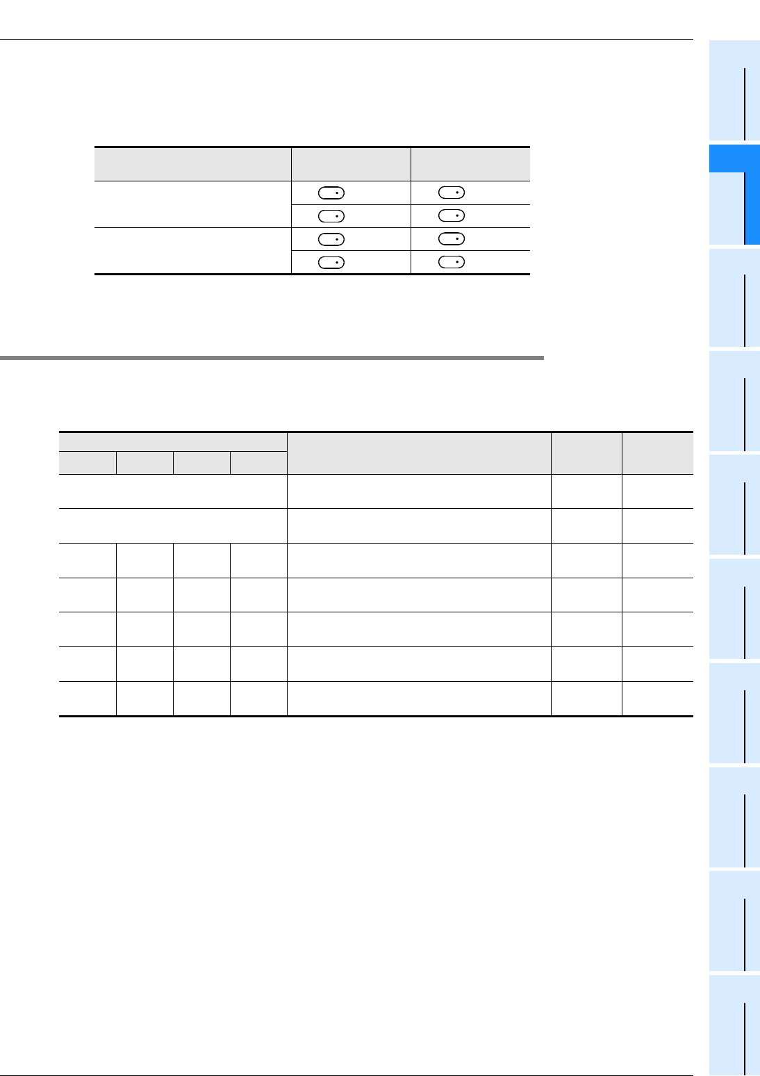
FX
3G
/FX
3U
/FX
3UC
PLC User's Manual - Positioning Control Edition
Built-in Positioning Functions
8 1-Speed Positioning - DRVI/DRVA Instruction
8.3 Drive To Absolute - DRVA Instruction
B - 119
A
Common Items
B
Built-in
Positioning
Functions
Apx.
Example
Connection
2 : When a high-speed output special adapter is used as a destination for pulse output on a FX3U PLC,
use the output shown in the following table for rotation direction signals.
When a built-in transistor output is used as a destination for pulse output on a FX3G/FX3U/FX3UC PLC,
use transistor output for signals rotation direction.
→ For the outputs applicable with a High-speed output special adapter, refer to Section 4.9.
3:D
.b is available only in FX3U and FX3UC PLCs. However, index modifiers (V and Z) are not available.
4 : Only available for FX3U and FX3UC PLCs.
8.3.2 List of Related Devices
1. Special auxiliary relays
The following table shows the related special auxiliary relays. Note that Y000, Y001, Y002, and Y003 are
devices that determine the pulse output destinations.
*1. Y002 is not available in 14-point and 24-point type FX3G PLC.
*2. Devices related to Y003 (pulse output destination) are only valid if two FX3U-2HSY-ADP adapters are
connected to the FX3U PLC.
*3. Cleared when the PLC switches from RUN to STOP.
High-speed output special
adapter connection position Pulse output Rotation direction
output
1st adapter = Y000 = Y004
= Y001 = Y005
2nd adapter = Y002 = Y006
= Y003 = Y007
Device number Function Attribute Refer to
Y000 Y001 Y002*1 Y003*2
M8029 "Instruction execution complete" flag Read only Subsection
4.4.2
M8329 "Instruction execution abnormal end" flag Read only Subsection
4.4.2
M8340 M8350 M8360 M8370 "Pulse output monitor" (BUSY/READY) flag Read only Subsection
4.4.3
M8343 M8353 M8363 M8373 Forward limit Drivable Subsection
4.3.1
M8344 M8354 M8364 M8374 Reverse limit Drivable Subsection
4.3.1
M8348 M8358 M8368 M8378 Positioning instruction activation Read only Subsection
4.4.4
M8349 M8359 M8369 M8379 Pulse output stop command*3 Drivable Subsection
4.3.2
D
1
D
2
D
1
D
2
D
1
D
2
D
1
D
2

FX
3G
/FX
3U
/FX
3UC
PLC User's Manual - Positioning Control Edition
Built-in Positioning Functions
8 1-Speed Positioning - DRVI/DRVA Instruction
8.3 Drive To Absolute - DRVA Instruction
B - 120
2. Special data registers
The following table shows the related special data registers. Note that Y000, Y001, Y002, and Y003 are
devices that determine the pulse output destinations.
*1. Y002 is not available in 14-point and 24-point type FX3G PLC.
*2. Devices related to Y003 (pulse output destination) are only valid if two FX3U-2HSY-ADP adapters are
connected to the FX3U PLC.
Device number Function Data
length
Default
value Refer to
Y000 Y001 Y002*1 Y003*2
D8340 Low-
order D8350 Low-
order D8360 Low-
order D8370 Low-
order Current value register
(PLS) 32-bit 0 Subsection
4.4.1
D8341 High-
order D8351 High-
order D8361 High-
order D8371 High-
order
D8342 D8352 D8362 D8372 Bias speed (Hz) 16-bit 0 Subsection
4.2.6
D8343 Low-
order D8353 Low-
order D8363 Low-
order D8373 Low-
order Maximum speed (Hz) 32-bit 100,000 Subsection
4.2.5
D8344 High-
order D8354 High-
order D8364 High-
order D8374 High-
order
D8345 D8355 D8365 D8375 Creep speed (Hz) 16-bit 1000 Subsection
4.2.4
D8346 Low-
order D8356 Low-
order D8366 Low-
order D8376 Low-
order Zero return speed (Hz) 32-bit 50,000 Subsection
4.2.3
D8347 High-
order D8357 High-
order D8367 High-
order D8377 High-
order
D8348 D8358 D8368 D8378 Acceleration time (ms) 16-bit 100 Subsection
4.2.7
D8349 D8359 D8369 D8379 Deceleration time (ms) 16-bit 100 Subsection
4.2.8
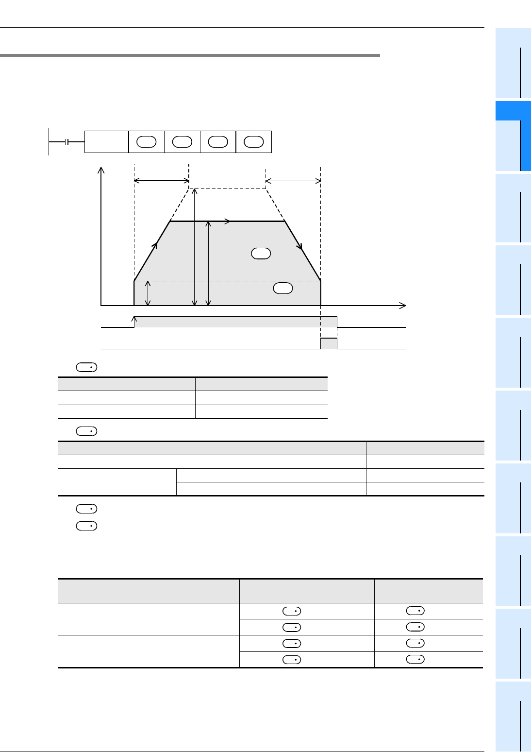
FX
3G
/FX
3U
/FX
3UC
PLC User's Manual - Positioning Control Edition
Built-in Positioning Functions
8 1-Speed Positioning - DRVI/DRVA Instruction
8.3 Drive To Absolute - DRVA Instruction
B - 121
A
Common Items
B
Built-in
Positioning
Functions
Apx.
Example
Connection
8.3.3 Function and Operation
This instruction uses an absolute drive method to perform a 1-speed positioning instruction.
For this instruction, the distance from the origin (zero point) to the target position should be specified.
→ For details on the "Instruction execution complete" flag, refer to Subsection 4.7.4.
→ For details on the maximum speed, bias speed, acceleration time,
and deceleration time, refer to Section 4.2.
1) For , specify the number of output pulses (absolute address value).
2) For , specify the output pulse frequency.
3) For , specify the pulse output number in the range of Y000 to Y003.
4) For , specify the rotation direction signal output device number.
When a high-speed output special adapter is used as a destination for pulse output on a FX3U PLC, use
the output shown in the following table for rotation direction signals.
When a built-in transistor output is used as a destination for pulse output on a FX3G/FX3U/FX3UC PLC,
use transistor output for signals rotation direction.
Setting range
16-bit operation -32,768 to +32,767
32-bit operation -999,999 to +999,999
Setting range
16-bit operation 10 to 32,767(Hz)
32-bit operation
When a high-speed output special adapter is used
10 to 200,000(Hz)
When a transistor output from the main unit is used
10 to 100,000(Hz)
High-speed output special adapter
connection position Pulse output destination device Rotation direction output
1st adapter = Y000 = Y004
= Y001 = Y005
2nd adapter = Y002 = Y006
= Y003 = Y007
Speed
Instruction execution
ON
Time
"Instruction
execution complete" flag
M8029
Maximum speed
Deceleration
time
Bias
speed
Acceleration
time
Output pulse
frequency
Number of output
pulses S
1
•
S
2
•
Command
input
FNC 159
DRVA S
1
•
S
2
•
D
1
•
D
2
•
S
1
S
2
D
1
D
2
D
1
D
2
D
1
D
2
D
1
D
2
D
1
D
2

FX
3G
/FX
3U
/FX
3UC
PLC User's Manual - Positioning Control Edition
Built-in Positioning Functions
8 1-Speed Positioning - DRVI/DRVA Instruction
8.3 Drive To Absolute - DRVA Instruction
B - 122
The rotation direction ON/OFF status of the specified device is shown in the following table.
During instruction execution, however, do not use the output for other purposes.
8.3.4 Important Points
→ For the important points of programming, refer to Section 4.7.
• If an the operand is changed during instruction execution, the change will be ignored and the operation will
not be affected.
Note that the changed operand will be enabled at the next activation of the instruction.
• If the instruction activation contact is turned off during execution of the instruction, the speed will
decelerate and the operation will stop.
In this case, the "Instruction execution complete" flag (M8029) will not be turned on.
• If the limit flag (forward limit relay or reverse limit relay) in the operation direction is turned on, the speed
will decelerate and the operation will stop. In this case, the "Instruction execution abnormal end" flag
(M8329) will be turned on when execution of the instruction is complete.
→ For details on the "Instruction execution abnormal end" flag, refer to Subsection 4.7.4.
• If the "pulse output monitor" (BUSY/READY) flag is on, a positioning instruction (including PLSR and
PLSY) that uses the same output cannot be executed.
If the "pulse output monitor" (BUSY/READY) flag is still on after the instruction activation contact is turned
off, do not execute a positioning instruction (including PLSR and PLSY instructions) that uses the same
output number.
ON/OFF status of device
specified by Rotation direction (increase/decrease current value)
ON
Forward rotation (Outputting pules from
will
increase the current value.)
The rotation direction (normal or reverse
rotation) depends on which value is larger;
the number of output pulses specified by
(absolute address) or the value
indicated in the current value register.
OFF Reverse rotation (Outputting pules from will
reduce the current value.)
D
2
D
2
D
1
S
D
1
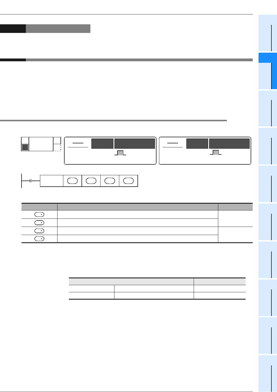
FX
3G
/FX
3U
/FX
3UC
PLC User's Manual - Positioning Control Edition
Built-in Positioning Functions
9 One-speed Interrupt constant quantity feed -DVIT Instruction
9.1 Instruction Format
B - 123
A
Common Items
B
Built-in
Positioning
Functions
Apx.
Example
Connection
9. One-speed Interrupt constant quantity feed -DVIT
Instruction
The built-in positioning function uses the Interrupt Positioning (DVIT) instruction to perform one-speed
interrupt constant quantity feed. If an FX3UC PLC Ver.1.30 or later is used, this instruction can change the
interruption signal input destination.
If an FX3U/FX3UC PLC Ver.2.20 or later is used, the interruption signal can be controlled with a user program.
The FX3G PLC does not support the interrupt positioning (DVIT) instruction.
→ For items to be observed in programming, refer to Section 4.7.
9.1 Instruction Format
1. Instruction Format
2. Data setting
*1. Setting range : -32,768 to +32,767 (excluding 0) for 16-bit operation
: -999,999 to +999,999 (excluding 0) for 32-bit operation
*2. Setting range : 10 to 32,767 Hz for 16-bit operation
For 32-bit operation, however, the setting range should be as shown in the following
table.
Operand type Description Data type
Specifies the number of pulses (relative address) to be output after interruption.*1
BIN16/32-bit
Specifies the output pulse frequency.*2
Specifies the pulse output number. Bit
Specifies the rotation direction signal output destination device number.
Pulse output destination Setting range
FX3U PLC High-speed output special adapter 10 to 200,000(Hz)
FX3U/FX3UC PLC Main unit (transistor output) 10 to 100,000(Hz)
FNC 151
DVIT
DRIVE INTERRUPT
D
16-bit
instruction
9 steps DVIT
-
Continuous
execution
type
Instruction
symbol Execution condition 32-bit
instruction Instruction
symbol Execution condition
DDVIT
-
Continuous
execution
type
17 steps
Command
input
FNC 151
DVIT S
2
•
S
1
•
D
1
•
D
2
•
S
1
S
2
D
1
D
2
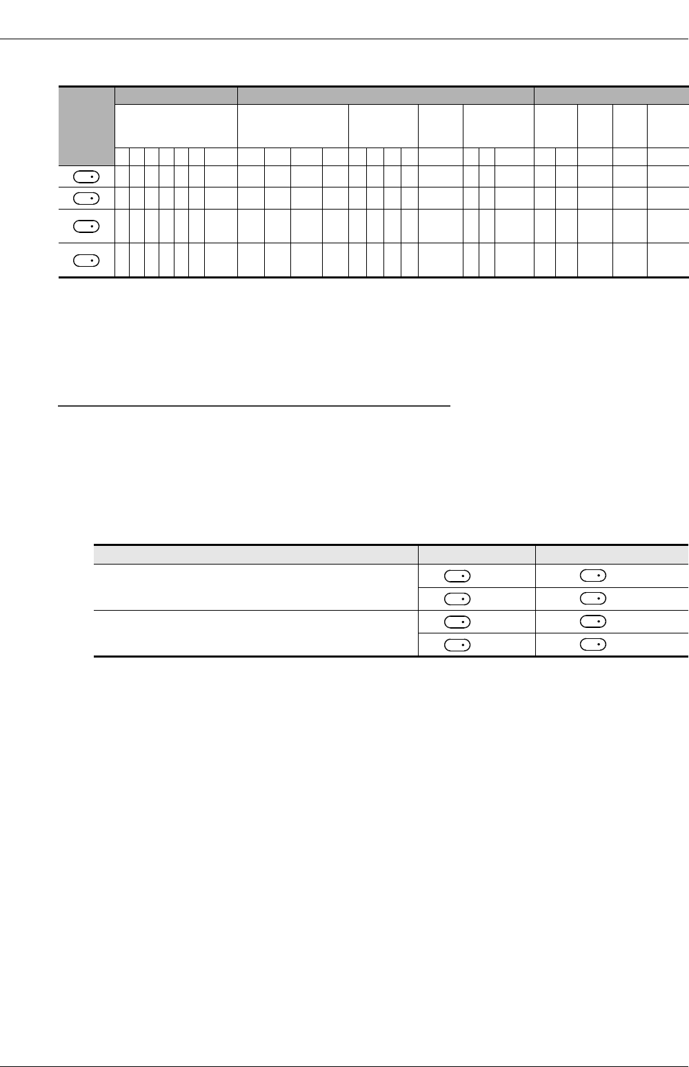
FX
3G
/FX
3U
/FX
3UC
PLC User's Manual - Positioning Control Edition
Built-in Positioning Functions
9 One-speed Interrupt constant quantity feed -DVIT Instruction
9.1 Instruction Format
B - 124
3. Devices
1 : Specify Y000, Y001, or Y002 transistor output from the main unit, or specify Y000, Y001, Y002*2, or
Y003*2 from a high-speed output special adapter*1.
*1. A high-speed input/output special adapter cannot be connected to the FX3UC PLC.
*2. To use Y002 and Y003 with a high-speed output special adapter, connect a second high-speed output
special adapter.
Point:
• To use an FX3U Series main unit of relay output type, be sure to connect a high-speed output special
adapter. Differential line drive type outputs will be used for the outputs of the high-speed output special
adapter.
2 : When a high-speed output special adapter is used as a destination for pulse output on a FX3U PLC,
use the output shown in the following table for rotation direction signals.
When a built-in transistor output is used as a destination for pulse output on a FX3U/FX3UC PLC, use
transistor output for signals rotation direction.
→ For the outputs applicable with a High-speed output special adapter, refer to Section 4.9.
3:D.b cannot be indexed by index registers (V and Z).
Operand
type
Bit device Word device Others
System user Digit designation System user Special
unit Index Con-
stant
Real
num-
ber
Char-
acter
string
Pointer
XYMTCSD
.b KnX KnY KnM KnS T C D R U\GV Z Modify K H E ""P
33 3 3
3333 3333
3 3 3 3 3333 3 3 3 3
13
23333
High-speed output special adapter connection position Pulse output Rotation direction output
1st adapter = Y000 = Y004
= Y001 = Y005
2nd adapter = Y002 = Y006
= Y003 = Y007
S
1
S
2
D
1
D
2
D
1
D
2
D
1
D
2
D
1
D
2
D
1
D
2

FX
3G
/FX
3U
/FX
3UC
PLC User's Manual - Positioning Control Edition
Built-in Positioning Functions
9 One-speed Interrupt constant quantity feed -DVIT Instruction
9.2 List of Related Devices
B - 125
A
Common Items
B
Built-in
Positioning
Functions
Apx.
Example
Connection
9.2 List of Related Devices
1. Special auxiliary relays
The following table shows the related special auxiliary relays. Note that Y000, Y001, Y002, and Y003 are
devices that determine the pulse output destinations.
*1. Devices related to Y003 (pulse output destination) are only valid if two FX3U-2HSY-ADP adapters are
connected to the FX3U PLC.
*2. This function is valid if Ver.1.30 or later is used.
*3. Cleared when the PLC switches from RUN to STOP.
*4. The logical NOT function is not valid for the user interrupt input command.
*5. This function is valid if Ver.2.20 or later is used.
Device number Function Attribute Refer to
Y000 Y001 Y002 Y003*1
M8029 "Instruction execution complete" flag Read only Subsection
4.4.2
M8329 "Instruction execution abnormal end" flag Read only Subsection
4.4.2
M8336*2 Interrupt input specification function enable*3 Drivable Subsection
4.3.7
M8340 M8350 M8360 M8370 "Pulse output monitor" (BUSY/READY) flag Read only Subsection
4.4.3
M8343 M8353 M8363 M8373 Forward limit Drivable Subsection
4.3.1
M8344 M8354 M8364 M8374 Reverse limit Drivable Subsection
4.3.1
M8347 M8357 M8367 M8377 Interrupt signal logic reverse*3*4 Drivable Subsection
4.3.8
M8348 M8358 M8368 M8378 Positioning instruction activation Read only Subsection
4.4.4
M8349 M8359 M8369 M8379 Pulse output stop command*3 Drivable Subsection
4.3.2
M8460*5 M8461*5 M8462*5 M8463*5 User interrupt input command*3 Drivable Subsection
4.3.7
M8464*5 M8465*5 M8466*5 M8467*5 CLEAR signal device specification function
enable*3 Drivable Subsection
4.3.4

FX
3G
/FX
3U
/FX
3UC
PLC User's Manual - Positioning Control Edition
Built-in Positioning Functions
9 One-speed Interrupt constant quantity feed -DVIT Instruction
9.2 List of Related Devices
B - 126
2. Special data registers
The following table shows the related special data registers. Note that Y000, Y001, Y002, and Y003 are
devices that determine the pulse output destinations.
*1. Devices related to Y003 (pulse output destination) are only valid if two FX3U-2HSY-ADP adapters are
connected to the FX3U PLC.
*2. This function is valid if Ver.1.30 or later is used.
However, to specify the user interrupt input command, Ver.2.20 or later should be used.
*3. This function is valid if Ver.2.20 or later is used.
Device number Function Data
length
Initial
value Refer to
Y000 Y001 Y002 Y003*1
D8336*2 Specification of
interrupt input. 16-bit - Subsection
4.3.7
D8340 Low-
order D8350 Low-
order D8360 Low-
order D8370 Low-
order Current value register
(PLS) 32-bit 0 Subsection
4.4.1
D8341 High-
order D8351 High-
order D8361 High-
order D8371 High-
order
D8342 D8352 D8362 D8372 Bias speed (Hz) 16-bit 0 Subsection
4.2.6
D8343 Low-
order D8353 Low-
order D8363 Low-
order D8373 Low-
order Maximum speed (Hz) 32-bit 100,000 Subsection
4.2.5
D8344 High-
order D8354 High-
order D8364 High-
order D8374 High-
order
D8348 D8358 D8368 D8378 Acceleration time (ms) 16-bit 100 Subsection
4.2.7
D8349 D8359 D8369 D8379 Deceleration time (ms) 16-bit 100 Subsection
4.2.8
D8464*3 D8465*3 D8466*3 D8467*3 Specifies the CLEAR
signal device. 16-bit - Subsection
4.3.4
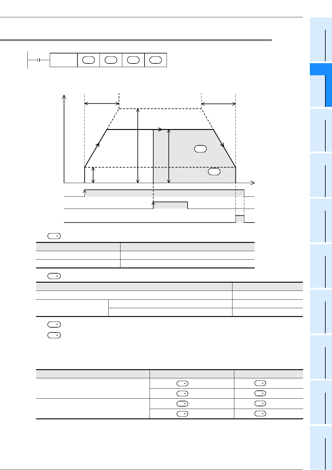
FX
3G
/FX
3U
/FX
3UC
PLC User's Manual - Positioning Control Edition
Built-in Positioning Functions
9 One-speed Interrupt constant quantity feed -DVIT Instruction
9.3 Function and Operation
B - 127
A
Common Items
B
Built-in
Positioning
Functions
Apx.
Example
Connection
9.3 Function and Operation
→ For details on the maximum speed, bias speed,acceleration time, and deceleration time, refer to
Subsection 4.2.5 to Subsection 4.2.8.
1) For , specify the number of output pulses (relative address value).
2) For , specify the output pulse frequency.
3) For , specify the pulse output number in the range of Y000 to Y003.
4) For , specify the rotation direction signal output device number.
When a high-speed output special adapter is used as a destination for pulse output on a FX3U PLC, use
the output shown in the following table for rotation direction signals.
When a built-in transistor output is used as a destination for pulse output on a FX3U/FX3UC PLC, use
transistor output for signals rotation direction.
Setting range
16-bit operation -32,768 to +32,767 (excluding 0)
32-bit operation -999,999 to +999,999 (excluding 0)
Setting range
16-bit operation 10 to 32,767(Hz)
32-bit operation When a high-speed output special adapter is used 10 to 200,000(Hz)
When a transistor output from the main unit is used 10 to 100,000(Hz)
High-speed output special adapter number Pulse output destination device Rotation direction output
1st adapter = Y000 = Y004
= Y001 = Y005
2nd adapter = Y002 = Y006
= Y003 = Y007
Command
input
FNC 151
DVIT S
2
•
S
1
•
D
1
•
D
2
•
ON
Instruction execution
Interrupt input
Time
Speed
"Instruction
execution complete" flag
M8029
Maximum speed
Deceleration
time
Bias
speed
Acceleration
time
Output pulse
frequency
Number of output
pulses S
1
•
S
2
•
S
1
S
2
D
1
D
2
D
1
D
2
D
1
D
2
D
1
D
2
D
1
D
2
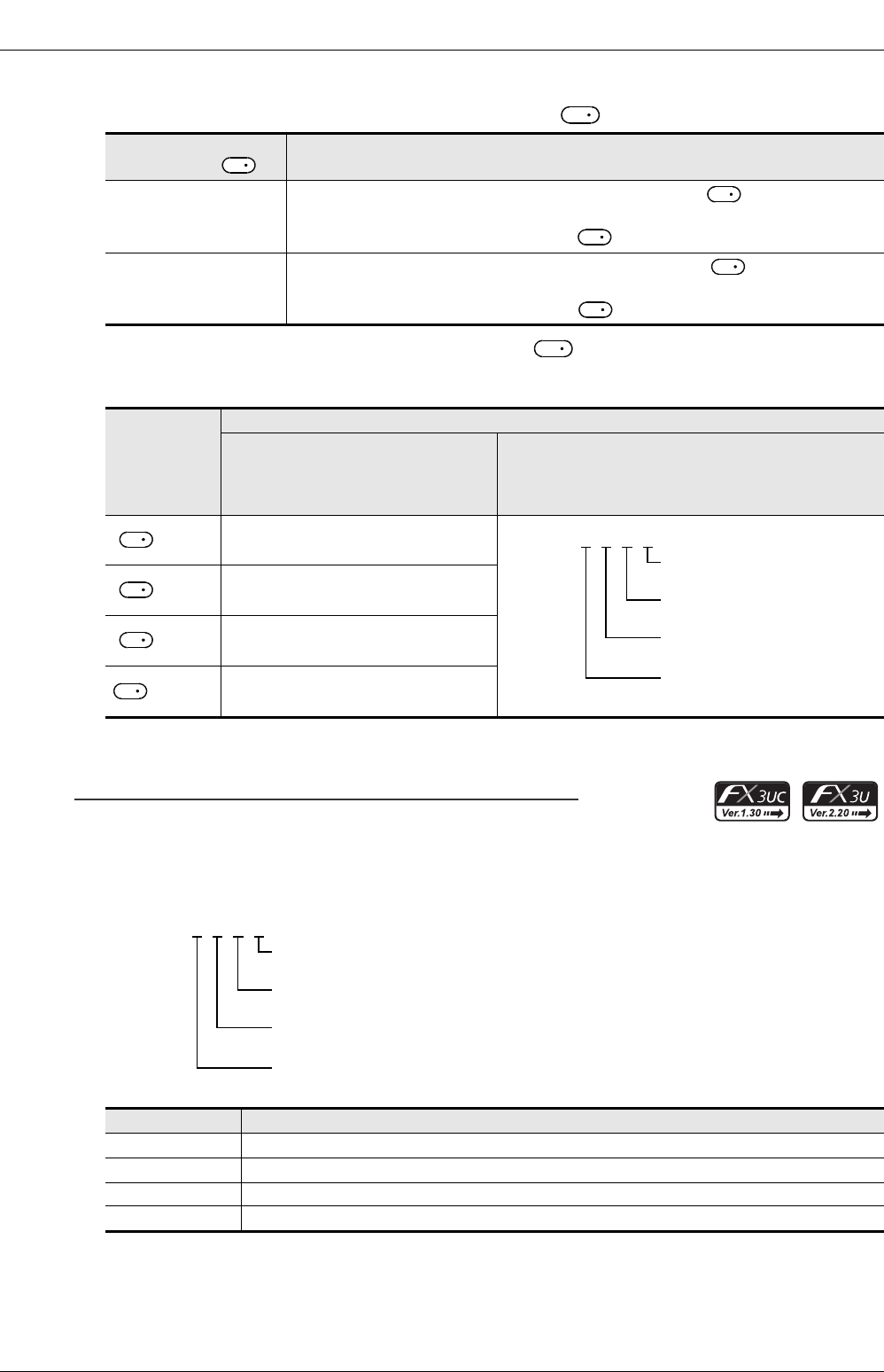
FX
3G
/FX
3U
/FX
3UC
PLC User's Manual - Positioning Control Edition
Built-in Positioning Functions
9 One-speed Interrupt constant quantity feed -DVIT Instruction
9.3 Function and Operation
B - 128
The rotation direction ON/OFF status of the specified device is shown in the following table.
During instruction execution, however, do not use the output for other purposes.
5) The interrupt input signal depends on the pulse output of as shown in the following table.
Use an FX3UC PLC Ver.1.30 or later to use the interrupt input specification function.
Use an FX3U/FX3UC PLC Ver.2.20 or later to set the user interrupt input command.
*1. Y003 can be specified as the pulse output destination only if two FX3U-2HSY-ADP adapters are connected to
the FX3U PLC.
Designation of interrupt input using M8336 interrupt input specification function:
1) Turn on the M8336.
2)
Set the interrupt input number (X000 to X007) in D8336, or specify the user interrupt input
command
*1
.
→ For details on the specification method, refer to Subsection 4.3.7 or Subsection 4.5.1.
ON/OFF status of device
specified by Rotation direction (increase/decrease current value)
ON
If the number of pulses to be output after interruption (specified by ) is set to a positive
number, the operation will be performed in the forward rotation direction.
Forward rotation (Outputting pulses from will increase the current value.)
OFF
If the number of pulses to be output after interruption (specified by ) is set to a
negative number, the operation will be performed in the reverse rotation direction.
Reverse rotation (Outputting pulses from will decrease the current value.)
Pulse output
destination
device
Interrupt input signal
If it is not necessary to use the
interrupt input specification
function (M8336 = OFF), or if the
FX3UC PLC below Ver.1.30 is used
If it is necessary to use the interrupt input
specification function
(M8336 = ON)
= Y000 X000
= Y001 X001
= Y002 X002
= Y003*1 X003
Setting value Description of setting
0 Specifies X000 for the interrupt input signal.
1 Specifies X001 for the interrupt input signal.
...
...
7 Specifies X007 for the interrupt input signal.
D
2
D
2
S
1
D
1
S
1
D
1
D
1
D
1
D8336=H
{
{
{
{
Interrupt input for Y000
(pulse output destination device
)
Interrupt input for Y001
(pulse output destination device
)
Interrupt input for Y002
(pulse output destination device
)
Interrupt input for Y003
(pulse output destination device
)
D
1
D
1
D
1
D8336=H
{
{
{
{
Interrupt input for Y000
(pulse output destination device)
Interrupt input for Y001
(pulse output destination device)
Interrupt input for Y002
(pulse output destination device)
Interrupt input for Y003
(pulse output destination device)

FX
3G
/FX
3U
/FX
3UC
PLC User's Manual - Positioning Control Edition
Built-in Positioning Functions
9 One-speed Interrupt constant quantity feed -DVIT Instruction
9.3 Function and Operation
B - 129
A
Common Items
B
Built-in
Positioning
Functions
Apx.
Example
Connection
*1. A device can only be specified if an FX3U/FX3UC PLC Ver.2.20 or later is used.
When using an FX3UC PLC below Ver.2.20, if "8" is set and then the specified Interrupt Positioning (DVIT)
instruction turns ON, an operation error (error code: K6763) will occur, and the instruction will not cause any
operation.
*2. Y003 can be specified as the pulse output destination only if two FX3U-2HSY-ADP adapters are connected to
the FX3U PLC.
*3. After setting a number in the range of 9 to E for the interrupt input signal, if the corresponding Interrupt
Positioning (DVIT) instruction turns ON, an operation error (error code: K6763) will occur, and the instruction
will not cause any operation.
8*1
Specifies a user
interrupt input command
*1 for the interrupt input
signal.
9 ~ E*3 Do not specify these values.
FSet "F" for a pulse output destination device if the device is not used for the Interrupt
Positioning (DVIT) instruction.
Setting value Description of setting
Pulse output destination device User interrupt input command
Y000 M8460
Y001 M8461
Y002 M8462
Y003*2 M8463
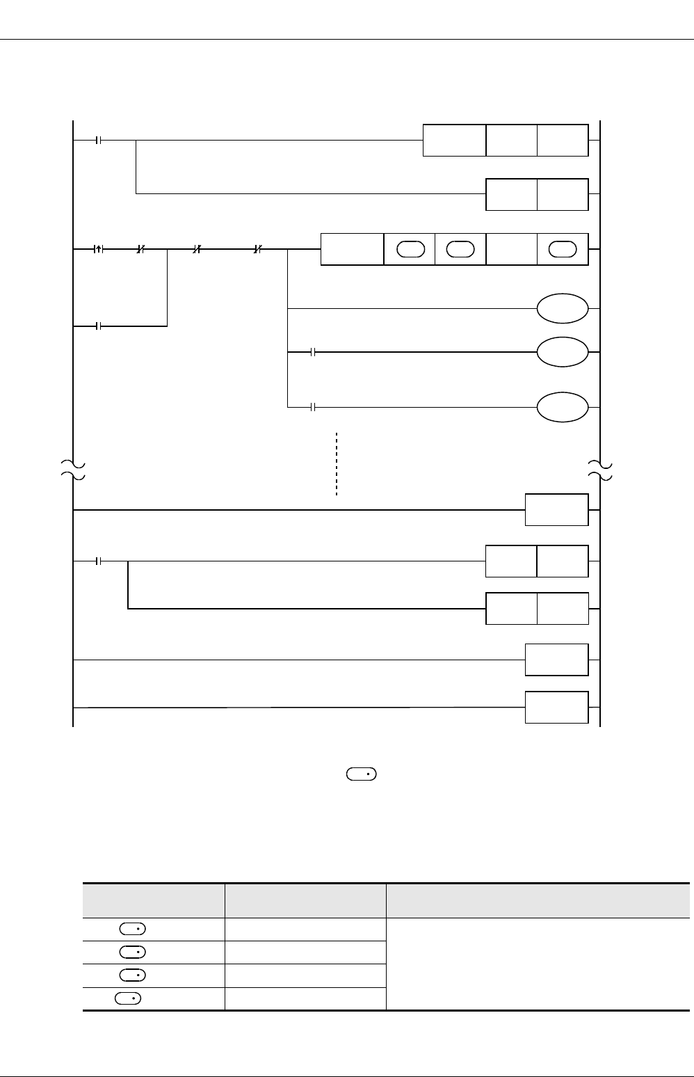
FX
3G
/FX
3U
/FX
3UC
PLC User's Manual - Positioning Control Edition
Built-in Positioning Functions
9 One-speed Interrupt constant quantity feed -DVIT Instruction
9.3 Function and Operation
B - 130
Example program:
The following program shows that the interrupt input for Y000 is set using the user interrupt input
command (M8460).
After specifying a user interrupt input command for the interrupt input signal, if the specified device is
turned on, the number of pulses specified by will be output and then the operation will be stopped.
Before activating the Interrupt Positioning instruction again, be sure to turn off the user interrupt input
command.
6) Interrupt input signal logical NOT
Turn the "Interrupt signal logic reverse" relay ON or OFF (see the following table) to specify the logic of
the interrupt input signal. However, if the user interrupt input command is set for the pulse output
destination device, the interrupt input signal logical NOT function cannot be used.
*1. Y003 can be specified as the pulse output destination only if two FX3U-2HSY-ADP adapters are connected to
the FX3U PLC.
Pulse output
destination device
"Interrupt signal logic
reverse" relay Description
= Y000 M8347
OFF: Positive logic (Turning the input ON will turn on
the interrupt input signal.)
ON: Negative logic (Turning the input OFF will turn
on the interrupt input signal.)
= Y001 M8357
= Y002 M8367
= Y003*1 M8377
M8002
Specifies the
interrupt input for
Y000 in the user
interrupt input
specification register.
M8336SET
Y000
Interrupt input
specification
function enable.
Executes DVIT
instruction
D8336HFFF8
FNC 12
MOV
FNC151
DVIT S
1
•
S
2
•
M8029
M8329
Initial pulse
Command
input
D
2
•
M8348
Positioning
being
performed
(Y000)
M101
Normal
end of
positioning
M102
Abnormal
end of
positioning
M100
M100
M101
M102
Interruption
positioning is
being
performed.
"Positioning
operation
normal end"
flag
"Positioning
operation
abnormal end"
flag
"Instruction execution complete" flag
"Instruction execution abnormal end" flag
Interruption
positioning being
performed
M8460
Interruption
condition
Interrupt input
signal: ON
FNC 06
FEND
Interruption
pointer I
0
SET
M8460RST
Interrupt input
signal: OFF
FNC 03
IRET
END
S
1
D
1
D
1
D
1
D
1
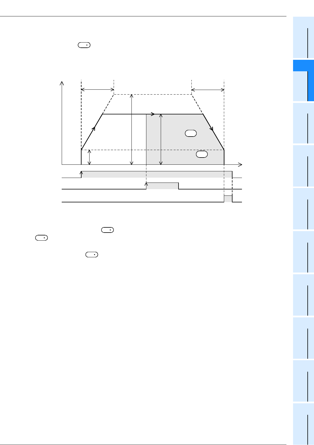
FX
3G
/FX
3U
/FX
3UC
PLC User's Manual - Positioning Control Edition
Built-in Positioning Functions
9 One-speed Interrupt constant quantity feed -DVIT Instruction
9.3 Function and Operation
B - 131
A
Common Items
B
Built-in
Positioning
Functions
Apx.
Example
Connection
1. Interruption positioning operation
The interruption positioning operation is described below assuming that Y000 is specified as the pulse output
destination device by .
For this reason, if Y001, Y002, or Y003 is specified, it is necessary to change the output number of each
related flag.
→ For details on related flags, refer to Section 4.1 to Section 4.4, or Section 9.2.
1) Execute the Interrupt Positioning (DVIT) instruction.
2) Transfer operation will be performed in the direction specified by the sign attached to the number of
output pulses (specified by ) at the speed specified by the output pulse frequency (specified by
).
3) If interrupt input X000 is turned on, pulses will be output until the number of output pulses reaches the
number specified by , and then the operation will stop.
4) The "instruction execution complete" flag (M8029) will turn on, and the interruption positioning operation
will be completed.
→ For details on "Instruction execution complete" flag,
refer to Subsection 4.7.4.
D
1
Deceleration
time
(D8349)
Bias speed
(D8342)
ON
Speed
Acceleration
time
(D8348)
Instruction execution
Interrupt input (X000)
"Instruction
execution complete" flag
M8029
Maximum speed
(D8344,D8343)
Time
Output pulse
frequency
Number of output
pulses S
1
•
S
2
•
S
1
S
2
S
1
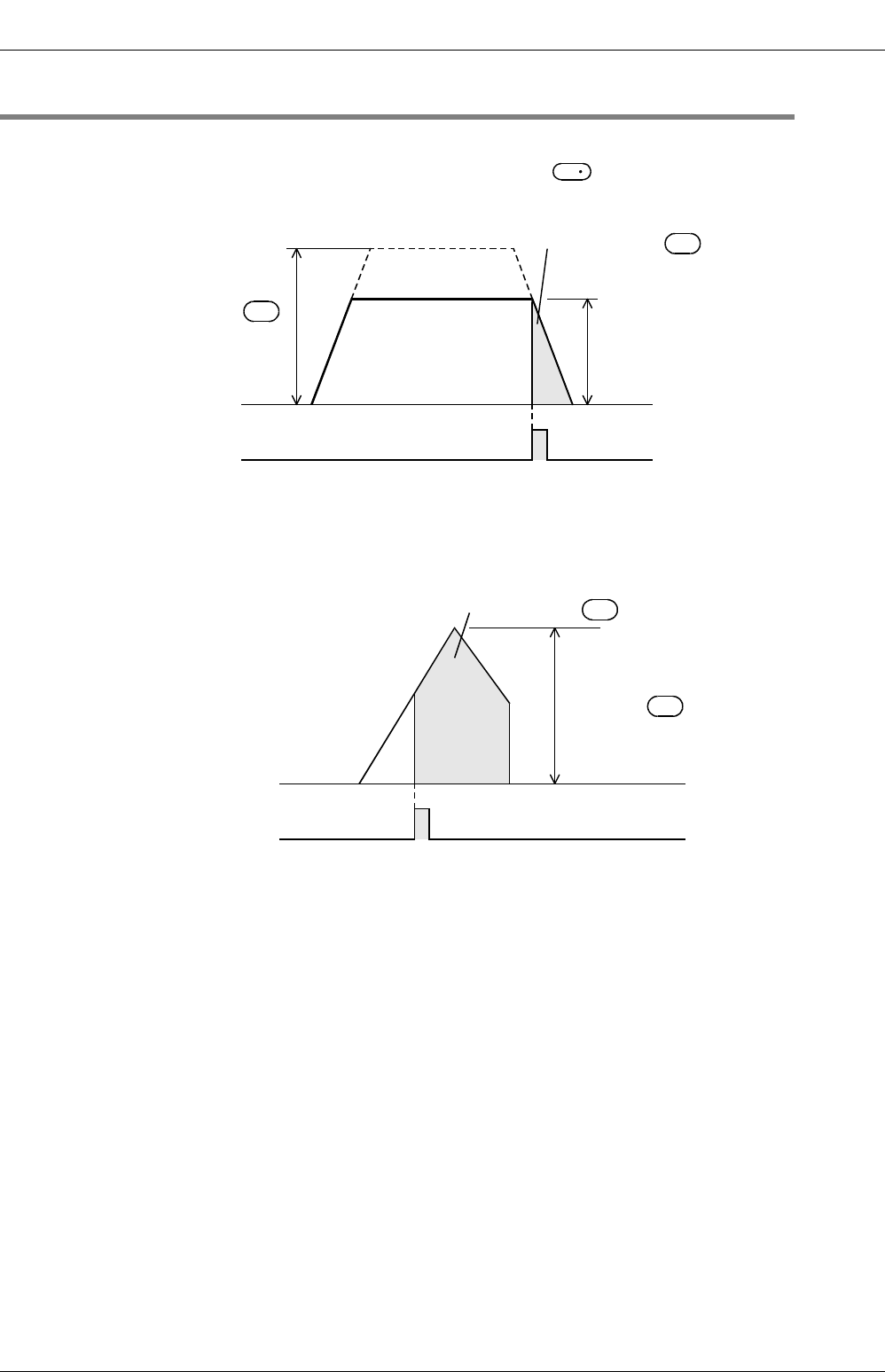
FX
3G
/FX
3U
/FX
3UC
PLC User's Manual - Positioning Control Edition
Built-in Positioning Functions
9 One-speed Interrupt constant quantity feed -DVIT Instruction
9.4 Important Points
B - 132
9.4 Important Points
→ For details on the instruction activation timing, refer to Section 4.7.
• If the speed is too high for the number of pulses specified by , the frequency will be reduced so that
the speed can be reduced within the specified number of output pulses.
• If there is a possibility for the interrupt input instruction to be turned on during acceleration, specify the
number of pulses so that the relation can be set to "number of output pulses ≥ number of pulses needed for
acceleration + number of pulses needed for deceleration".
If the relation is set to "number of output pulses < number of pulses needed for acceleration + number of
pulses needed for deceleration", the operation will be as shown in the following figure:
• If the interrupt input turns ON before execution of the instruction, the operation will be performed in the
same way as the DRVI instruction.
• If an operand is changed during instruction execution, the change will be ignored and the operation will not
be affected. To reflect the change on the operation, turn off the command contact of the instruction, and
then turn it on again.
• If the instruction activation contact is turned off during operation, the speed will decelerate and the
operation will stop. In this case, the "Instruction execution complete" flag (M8029) will not be turned on.
• Input the interruption signal before the number of output pulses reaches 4,294,967,296. If the number of
pulses reaches 4,294,967,296 before inputting the interruption signal, the operation will stop, and the
"Instruction execution complete" flag (M8029) will be turned on.
→ For details on "Instruction execution complete" flag,
refer to Subsection 4.7.4.
• If the "pulse output monitor" (BUSY/READY) flag is on, a positioning instruction (including PLSR and
PLSY) that uses the same output cannot be executed.
If the "pulse output monitor" (BUSY/READY) flag is still on after the instruction activation contact is turned
off, do not execute a positioning instruction (including PLSR and PLSY instructions) that uses the same
output number.
• If the forward limit relay or the reverse limit relay in the operation direction is turned on, the speed will
decelerate and the operation will stop. In this case, the "Instruction execution abnormal end" flag (M8329)
will turn when execution of the instruction is complete.
→ For details on "Instruction execution abnormal end" flag, refer to Subsection 4.7.4.
S
1
Output pulse
frequency
specified by S
2
•
S
1
•
Actual output
pulse frequency
Number of output
pulses specified by
Interrupt input
Output pulse
frequency
specified by S
2
•
S
1
•
Number of output
pulses specified by
Interrupt input

FX
3G
/FX
3U
/FX
3UC
PLC User's Manual - Positioning Control Edition
Built-in Positioning Functions
9 One-speed Interrupt constant quantity feed -DVIT Instruction
9.4 Important Points
B - 133
A
Common Items
B
Built-in
Positioning
Functions
Apx.
Example
Connection
• The interrupt input cannot be used for the following items:
Interrupt inputs can only be specified when using Ver.1.30 or later.
- High-speed counter
- Input interruption
- Pulse catch
- SPD instruction
- DSZR instruction
- ZRN instruction
FX
3G
/FX
3U
/FX
3UC
PLC User's Manual - Positioning Control Edition
Built-in Positioning Functions
10 Variable Speed Operation (Variable Speed Pulse Output)-PLSV Instruction
10.1 Instruction Format
B - 134
10. Variable Speed Operation
(Variable Speed Pulse Output)-PLSV Instruction
The built-in positioning function uses the variable speed pulse output (PLSV) instruction equipped with the
rotation direction designation function to perform variable speed operation. If an FX3U/FX3UC PLC Ver.2.20 or
later or FX3G PLC is used, this instruction can change the speed using the acceleration/deceleration speed.
10.1 Instruction Format
1. Instruction Format
2. Data setting
*1. Setting range : -32,768 Hz to -1 Hz and +1 Hz to 32,767 Hz for 16-bit operation. For the
32-bit operation, however, the setting range should be as shown in the following table.
3. Devices
1 : Specify Y000, Y001, or Y002*1 transistor output from the main unit, or specify Y000, Y001, Y002*3, or
Y003*3 from a high-speed output special adapter*2.
*1. Y002 is not available in 14-point and 24-point type FX3G PLC.
*2. High-speed input/output special adapters can be connected only to the FX3U PLC.
*3. To use Y002 and Y003 with a high-speed output special adapter, connect a second high-speed output
special adapter.
Operand type Description Data type
Specifies the output pulse frequency designation device number.*1 BIN 16/32-bit
Specifies the pulse output device number. Bit
Specifies the rotation direction signal output destination device number.
Pulse output destination Setting range
FX3U PLC High-speed output special adapter -200,000 to -1 to +1 to 200,000(Hz)
FX3G/FX3U/FX3UC
PLC Main unit (transistor output) -100,000 to -1 to +1 to 100,000(Hz)
Operand
type
Bit device Word device Others
System user Digit designation System
user
Special
unit Index Con-
stant
Real
num-
ber
Char-
acter
string
Pointer
XYMTCSD
.b KnX KnY KnM KnS T C D R U\GV Z Modify K H E ""P
33333333
433 3 3 3
13
233
33
32-bit
instruction
17 steps DPLSV Continuous
execution
type
Instruction
symbol Execution condition
-
FNC 157
PLSV
PULSE V
D
16-bit
instruction
9 steps PLSV Continuous
execution
type
Instruction
symbol Execution condition
-
S
D
1
D
2
S
D
1
D
2
FX
3G
/FX
3U
/FX
3UC
PLC User's Manual - Positioning Control Edition
Built-in Positioning Functions
10 Variable Speed Operation (Variable Speed Pulse Output)-PLSV Instruction
10.2 List of Related Devices
B - 135
A
Common Items
B
Built-in
Positioning
Functions
Apx.
Example
Connection
Point:
• To use an FX3U Series main unit of relay output type, be sure to connect a high-speed output special
adapter. Differential line drive type outputs will be used for the outputs of the high-speed output special
adapter.
2 : When a high-speed output special adapter is used as a destination for pulse output on a FX3U PLC,
use the output shown in the following table for rotation direction signals.
When a built-in transistor output is used as a destination for pulse output on a FX3G/FX3U/FX3UC PLC,
use transistor output for signals rotation direction.
3:D
.b is available only in FX3U and FX3UC PLCs. However, index modifiers (V and Z) are not available.
4 : Only available for FX3U and FX3UC PLCs.
10.2 List of Related Devices
1. Special auxiliary relays
The following table shows the related special auxiliary relays. Note that Y000, Y001, Y002, and Y003 are
devices that determine the pulse output destinations.
*1. Y002 is not available in 14-point and 24-point type FX3G PLC.
*2. Devices related to Y003 (pulse output destination) are only valid if two FX3U-2HSY-ADP adapters are
connected to the FX3U PLC.
*3. Only available for FX3U/FX3UC PLC Ver. 2.20 or later and FX3G PLC.
*4. Cleared when the PLC switches from RUN to STOP.
High-speed output special
adapter connection position Pulse output Rotation direction output
1st adapter = Y000 = Y004
= Y001 = Y005
2nd adapter = Y002 = Y006
= Y003 = Y007
Device number Function Attribute Refer to
Y000 Y001 Y002*1 Y003*2
M8029 "Instruction execution complete" flag Read only Subsection 4.4.2
M8329 "Instruction execution abnormal end"
flag Read only Subsection 4.4.2
M8338*3 Acceleration/deceleration*4 Drivable Subsection 4.3.9
M8340 M8350 M8360 M8370 "Pulse output monitor" (BUSY/READY)
flag Read only Subsection 4.4.3
M8343 M8353 M8363 M8373 Forword limit Drivable Subsection 4.3.1
M8344 M8354 M8364 M8374 Reverse limit Drivable Subsection 4.3.1
M8348 M8358 M8368 M8378 Positioning instruction activation Read only Subsection 4.4.4
D
1
D
2
D
1
D
2
D
1
D
2
D
1
D
2

FX
3G
/FX
3U
/FX
3UC
PLC User's Manual - Positioning Control Edition
Built-in Positioning Functions
10 Variable Speed Operation (Variable Speed Pulse Output)-PLSV Instruction
10.2 List of Related Devices
B - 136
2. Special data registers
The following table shows the related special data registers. Note that Y000, Y001, Y002, and Y003 are
devices that determine the pulse output destinations.
*1. Y002 is not available in 14-point and 24-point type FX3G PLC.
*2. Devices related to Y003 (pulse output destination) are only valid if two FX3U-2HSY-ADP adapters are
connected to the FX3U PLC.
*3. This device is valid for the PLSV instruction only when the acceleration/deceleration operation is performed in
the FX3U/FX3UC PLC Ver. 2.20 or later or FX3G PLC.
Device number Function Data
length
Initial
value Refer to
Y000 Y001 Y002*1 Y003*2
D8340 Low-
order D8350 Low-
order D8360 Low-
order D8370 Low-
order Current value register
(PLS) 32-bit 0 Subsection
4.4.1
D8341 High-
order D8351 High-
order D8361 High-
order D8371 High-
order
D8342 D8352 D8362 D8372 Bias speed (Hz) 16-bit 0 Subsection
4.2.6
D8343 Low-
order D8353 Low-
order D8363 Low-
order D8373 Low-
order Maximum speed (Hz) 32-bit 100,000 Subsection
4.2.5
D8344 High-
order D8354 High-
order D8364 High-
order D8374 High-
order
D8348 D8358 D8368 D8378 Acceleration time
(ms)*3 16-bit 100 Subsection
4.2.7
D8349 D8359 D8369 D8379 Deceleration time
(ms)*3 16-bit 100 Subsection
4.2.8
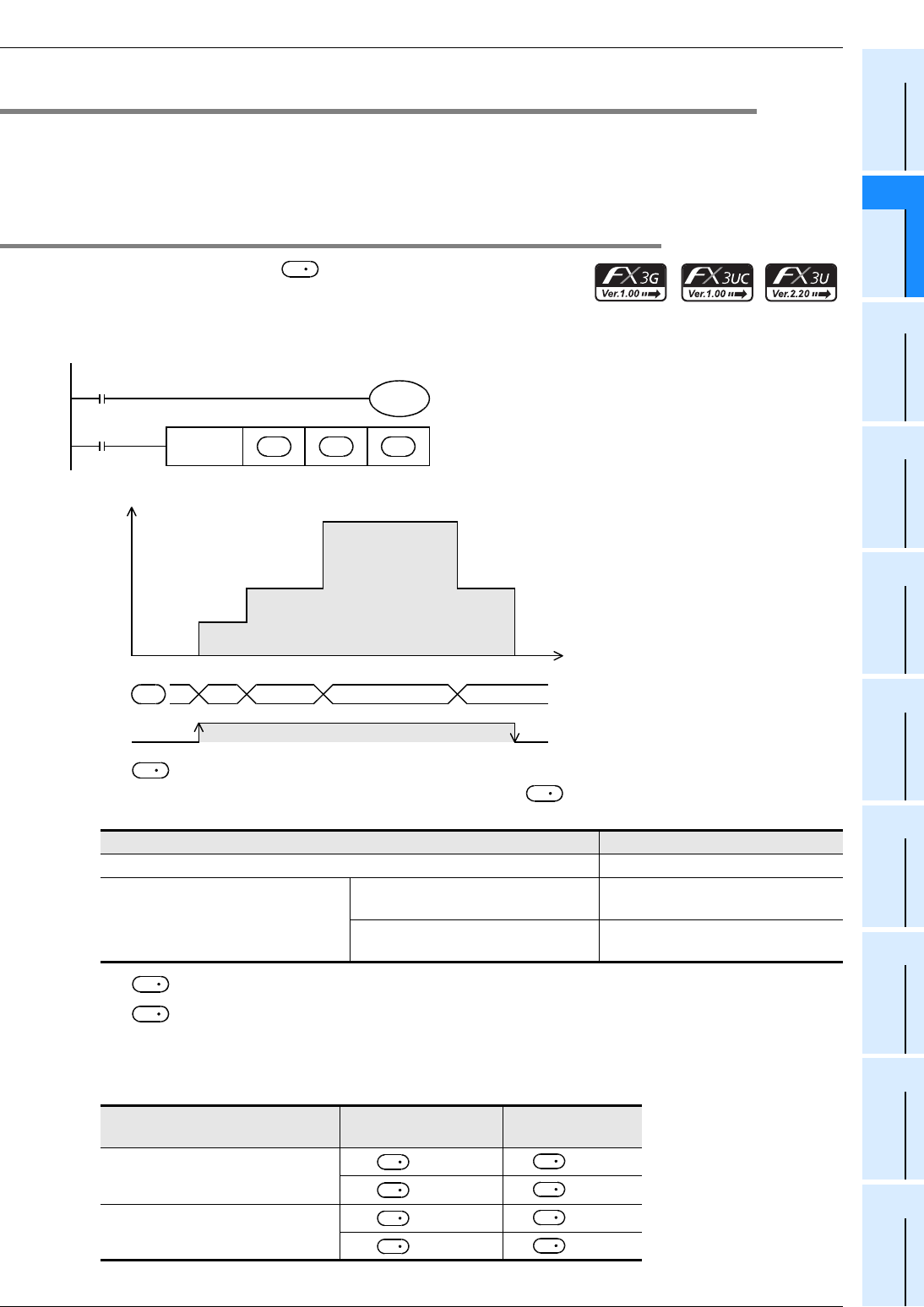
FX
3G
/FX
3U
/FX
3UC
PLC User's Manual - Positioning Control Edition
Built-in Positioning Functions
10 Variable Speed Operation (Variable Speed Pulse Output)-PLSV Instruction
10.3 Function and Operation
B - 137
A
Common Items
B
Built-in
Positioning
Functions
Apx.
Example
Connection
10.3 Function and Operation
The variable speed pulse output instruction changes the speed while using the rotation direction output.
The acceleration/deceleration function applies for the variable speed pulse output (PLSV) instruction, which
makes it possible to specify whether acceleration/deceleration will be used or not.
If an FX3UC PLC below Ver.2.20 is used, operation will be performed without acceleration/deceleration.
10.3.1 Operation without Acceleration/Deceleration (M8338 = OFF)
If the output pulse frequency value is changed after turning the
acceleration/deceleration function (M8338) OFF, the variable speed
pulse output (PLSV) instruction will change the output frequency without
using acceleration/deceleration.
→ For details on the maximum speed and bias speed, refer to Subsection 4.2.5 and Subsection 4.2.6.
1) For , specify the output pulse frequency.
Even if pulses are being output, the output pulse frequency can be changed freely.
Acceleration/deceleration, however, will not be performed.
2) For , specify the pulse output number in the range of Y000 to Y003.
3) For , specify the rotation direction signal output device number.
When a high-speed output special adapter is used as a destination for pulse output on a FX3U PLC, use
the output shown in the following table for rotation direction signals.
When a built-in transistor output is used as a destination for pulse output on a FX3G/FX3U/FX3UC PLC,
use transistor output for signals rotation direction.
Setting range
16-bit operation -32,768 to -1 Hz, 1 to 32,767 Hz
32-bit operation
When a high-speed output special
adapter is used -200,000 to -1 Hz, 1 to 200,000 Hz
When a transistor output from the
main unit is used -100,000 to -1 Hz, 1 to 100,000 Hz
High-speed output special
adapter number
Pulse output
destination device
Rotation direction
output
1st adapter = Y000 = Y004
= Y001 = Y005
2nd adapter = Y002 = Y006
= Y003 = Y007
S
M8001
FNC 157
PLSV S
•
D
1
•
D
2
•
M8338
Command
input
ON
S
•
100 250 500 250
Speed
Time
OFF
Instruction
Activation contact
S
S
D
1
D
2
D
1
D
2
D
1
D
2
D
1
D
2
D
1
D
2
FX
3G
/FX
3U
/FX
3UC
PLC User's Manual - Positioning Control Edition
Built-in Positioning Functions
10 Variable Speed Operation (Variable Speed Pulse Output)-PLSV Instruction
10.3 Function and Operation
B - 138
The rotation direction ON/OFF status of the specified device is shown in the following table.
During instruction execution, however, do not use the output for other purposes.
10.3.2 Operation with Acceleration/Deceleration (M8338 = ON)
If the output pulse frequency value is changed after turning the
acceleration/deceleration (M8338) ON, the variable speed pulse output
(PLSV) instruction will accelerate or decelerate to the changed output.
If a FX3UC PLC below Ver.2.20 is used, operation will be performed without acceleration/deceleration.
→ For details on the maximum speed, bias speed, acceleration time, and deceleration time, refer to
Subsection 4.2.5 to Subsection 4.2.8.
1) For , specify the output pulse frequency.
Even if pulses are being output, the output pulse frequency can be changed freely. Acceleration/
deceleration will be performed.
2) For , specify the pulse output number in the range of Y000 to Y003.
ON/OFF status of
device specified
by
Rotation direction (increase/decrease current value)
ON
If the number of output pulses specified by is a positive number, the operation will
be performed in the forward rotation direction.
Forward rotation (Outputting pulses from will increase the current value.)
OFF
If the number of output pulses specified by is a negative number, the operation
will be performed in the reverse rotation direction.
Reverse rotation (Outputting pulses from will decrease the current value.)
Setting range
16-bit operation -32,768 to -1 Hz, 1 to 32,767 Hz
32-bit operation
When a high-speed output special
adapter is used -200,000 to -1 Hz, 1 to 200,000 Hz
When a transistor output from the
main unit is used -100,000 to -1 Hz, 1 to 100,000 Hz
D
2
D
2
S
D
1
S
D
1
S
M8000
FNC 157
PLSV S
•
D
1
•
D
2
•
M8338
Command
input
ON
S
•
100 250 500 250
Speed
Time
OFF
Instruction
Activation contact
Maximum speed Initial value: 100,000 Hz
Output
pulse
frequency
S
•
Deceleration timeAcceleration time
Bias speed
Initial value: 0 Hz
Bias speed
Initial value: 100 ms Initial value: 100 ms
S
S
D
1
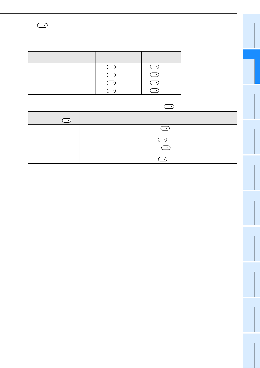
FX
3G
/FX
3U
/FX
3UC
PLC User's Manual - Positioning Control Edition
Built-in Positioning Functions
10 Variable Speed Operation (Variable Speed Pulse Output)-PLSV Instruction
10.3 Function and Operation
B - 139
A
Common Items
B
Built-in
Positioning
Functions
Apx.
Example
Connection
3) For , specify the rotation direction signal output device number.
When a high-speed output special adapter is used as a destination for pulse output on a FX3U PLC, use
the output shown in the following table for rotation direction signals.
When a built-in transistor output is used as a destination for pulse output on a FX3G/FX3U/FX3UC PLC,
use transistor output for signals rotation direction.
The rotation direction ON/OFF status of the specified device is shown in the following table.
During execution of this instruction, however, do not use the output for other purposes.
High-speed output special
adapter number
Pulse output
destination device
Rotation direction
output
1st adapter = Y000 = Y004
= Y001 = Y005
2nd adapter = Y002 = Y006
= Y003 = Y007
ON/OFF status of device
specified by Rotation direction (increase/decrease current value)
ON
If the number of output pulses specified by is a positive number, the operation
will be performed in the forward rotation direction.
Forward rotation (Outputting pulses from will increase the current value.)
OFF
If the number of output pulses specified by is a negative number, the
operation will be performed in the reverse rotation direction.
Reverse rotation (Outputting pulses from will decrease the current value.)
D
2
D
1
D
2
D
1
D
2
D
1
D
2
D
1
D
2
D
2
D
2
S
D
1
S
D
1
FX
3G
/FX
3U
/FX
3UC
PLC User's Manual - Positioning Control Edition
Built-in Positioning Functions
10 Variable Speed Operation (Variable Speed Pulse Output)-PLSV Instruction
10.4 Important Points
B - 140
10.4 Important Points
→ For important programming points, refer to Section 4.7.
• During pulse output operation, if the output pulse frequency is changed to "K0", the PLC will reduce
the speed and then stop the pulse outputting operation if the acceleration/deceleration function is ON.
However, if the acceleration/deceleration function is not activated, the PLC will immediately stop the pulse
outputting operation.
Before outputting pulses again, check that the "pulse output monitor" (BUSY/READY) flag is off, and then
wait until 1 or more cycles of operation have been completed. After that, set (change) the output pulse
frequency to a value other than "K0".
• During pulse outputting operation, do not change the sign attached to the output pulse frequency
value .
If it is necessary to change the sign, stop the servo motor first by setting the output pulse frequency value
to "K0", and wait for the motor to stop completely after decelerating to stop. And then, change the
sign attached to the output pulse frequency value .
If the sign attached to the output pulse frequency value is changed during pulse outputting
operation, the operation may be changed as follows, and the machine, therefore, may be damaged:
1) The pulse outputting operation may be stopped.
2) "Pulse output monitor" (BUSY/READY) flag may be turned off.
(The pulse outputting operation may be stopped, but the motor may not be stopped immediately.)
3) Operation may be performed in the specified direction at the frequency specified by the output
pulse frequency value .
• If the instruction activation contact is turned off during pulse outputting operation while the acceleration/
deceleration function is ON, the speed will decelerate and the operation will stop.
If the instruction activation contact is turned off during pulse outputting operation while the acceleration/
deceleration function is OFF, the operation will stop immediately. In both cases, the "Instraction execution
complete" flag (M8029) will not turn on.
• If a limit flag (forward / reverse rotation) in the operation direction is turned on, the operation will stop
immediately. In this case, the "Instruction execution abnormal end" flag (M8329) will turn on when
execution of the instruction is complete.
→ For details on the "Instruction execution abnormal end" flag, refer to Subsection 4.7.4.
• If the "pulse output monitor" (BUSY/READY) flag is on, a positioning instruction (including PLSR and
PLSY) that uses the same output cannot be executed.
If the "pulse output monitor" (BUSY/READY) flag is still on after the instruction activation contact is turned
off, do not execute a positioning instruction (including PLSR and PLSY instructions) that uses the same
output number.
• After executing the instruction, the rotation direction signal output will turn off.
1. Important items for FX3UC PLCs below Ver.2.20
• Acceleration/deceleration will not be performed when starting or stopping the operation. For this reason, if
it is necessary to use the cushion start function or the cushion stop function, increase/decrease the output
pulse frequency value using the FNC67 (RAMP) instruction, etc.
2. Important items for FX3U/FX3UC PLCs Ver.2.20 or later and FX3G
PLCs
• If acceleration/deceleration is enabled, the variable speed pulse output (PLSV) instructions for all of the
pulse output destination devices will use acceleration/deceleration. This means that acceleration/
deceleration cannot be specified separately for each pulse output destination device.
S
S
S
S
S
S
S
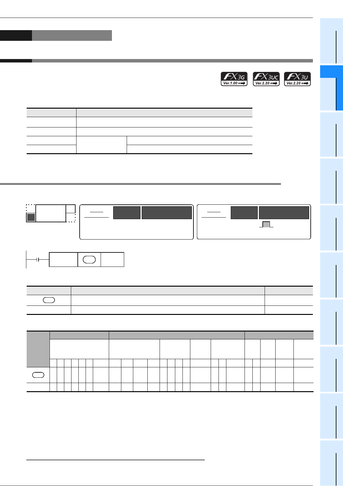
FX
3G
/FX
3U
/FX
3UC
PLC User's Manual - Positioning Control Edition
Built-in Positioning Functions
11 Batch Data Positioning Mode (TBL Instruction)
11.1 Instruction Format
B - 141
A
Common Items
B
Built-in
Positioning
Functions
Apx.
Example
Connection
11. Batch Data Positioning Mode (TBL Instruction)
If GX Developer Ver.8.23Z or later is used, the positioning instructions
shown below can be preliminarily set in the positioning tables. After that,
if a table is specified, the positioning operation of the specified table will
be performed.
*1. Only available for FX3U and FX3UC PLCs.
11.1 Instruction Format
1. Instruction Format
2. Data setting
3. Devices
1 : Specify Y000, Y001, or Y002*1 transistor output from the main unit, or specify Y000, Y001, Y002*3, or
Y003*3 from a high-speed output special adapter*2.
*1. Y002 is not available in 14-point and 24-point type FX3G PLC.
*2. High-speed input/output special adapters can be connected only to the FX3U PLC.
*3. To use Y002 and Y003 with a high-speed output special adapter, connect a second high-speed output
special adapter.
Point:
To use an FX3U Series main unit of relay output type, be sure to connect a high-speed output special adapter.
Differential line drive type outputs will be used for the outputs of the high-speed output special adapter.
Instruction Description
DVIT*1(FNC151) One-speed interrupt constant quantity feed (Interrupt positioning)
PLSV(FNC157) Variable speed operation (Variable Speed Pulse Output)
DRVI(FNC158) 1-speed
positioning
Drive to Increment
DRVA(FNC159) Drive to Absolute
Operand type Description Data type
Specifies the pulse output number. Bit
n Specifies the table number (1 to 100) to be executed. BIN 32-bit
Operand
type
Bit device Word device Others
System user Digit designation System user Special
unit Index Con-
stant
Real
num-
ber
Char-
acter
string
Pointer
XYMTCSD.b KnX KnY KnM KnS T C D R U\GVZModifyKH E ""P
1
n33
32-bit
instruction
17 steps DTBL Continuous
execution
type
Instruction
symbol Execution condition
-
16-bit
instruction
-
-
Instruction
symbol Execution condition
FNC 152
TBL
TABLE
D
Command
input
FNC152
DTBL D n
D
D

FX
3G
/FX
3U
/FX
3UC
PLC User's Manual - Positioning Control Edition
Built-in Positioning Functions
11 Batch Data Positioning Mode (TBL Instruction)
11.2 List of Related Devices
B - 142
11.2 List of Related Devices
1. Special auxiliary relays
The following table shows the related special auxiliary relays. Note that Y000, Y001, Y002, and Y003 are
devices that determine the pulse output destinations.
Device number Function Attribute Refer to
Y000 Y001 Y002*1 Y003*2
M8029 "Instruction execution complete" flag Read only Subsection
4.4.2
M8329 "Instruction execution abnormal end" flag Read only Subsection
4.4.2
M8338 Acceleration/deceleration operation*4, *7 Drivable Subsection
4.3.9
M8336 Interrupt input specification function enable*4, *5 Drivable Subsection
4.3.7
M8340 M8350 M8360 M8370 "Pulse output monitor"(BUSY/READY) flag Read only Subsection
4.4.3
M8343 M8353 M8363 M8373 Forward limit Drivable Subsection
4.3.1
M8344 M8354 M8364 M8374 Reverse limit Drivable Subsection
4.3.1
M8347 M8357 M8367 M8377 Interrupt signal logic reverse*4, *6 Drivable Subsection
4.3.8
M8348 M8358 M8368 M8378 Positioning instruction activation Read only Subsection
4.4.4
M8349 M8359 M8369 M8379 Pulse output stop command*4 Drivable Subsection
4.3.2
M8460 M8461 M8462 M8463 User interrupt input command*3*, 4 Drivable Subsection
4.3.7
*1. Y002 is not available in 14-point and 24-point type FX3G PLC.
*2. Devices related to Y003 (pulse output destination) are only valid if two FX3U-2HSY-ADP adapters are
connected to the FX3U PLC.
*3. Only available for FX3U/FX3UC PLC Ver. 2.20 or later.
*4. Cleared when the PLC switches from RUN to STOP.
*5. Only available for FX3U/FX3UC PLC Ver. 1.30 or later.
*6. The logical NOT function is not valid for the user interrupt input command.
*7. Only available for FX3U/FX3UC PLC Ver. 2.20 or later and FX3G PLC.

FX
3G
/FX
3U
/FX
3UC
PLC User's Manual - Positioning Control Edition
Built-in Positioning Functions
11 Batch Data Positioning Mode (TBL Instruction)
11.2 List of Related Devices
B - 143
A
Common Items
B
Built-in
Positioning
Functions
Apx.
Example
Connection
2. Special data registers
The following table shows the related special data registers. Note that Y000, Y001, Y002, and Y003 are
devices that determine the pulse output destinations. To set the constants shown in the shaded area, set the
positioning parameters.
→ For details on the positioning parameters, refer to Section 11.4.
*1. Y002 is not available in 14-point and 24-point type FX3G PLC.
*2. Devices related to Y003 (pulse output destination) are only valid if two FX3U-2HSY-ADP adapters are
connected to the FX3U PLC.
*3. This function is valid if Ver.1.30 or later is used.
However, the user interrupt input command can be specified only if the FX3U/FX3UC PLC Ver.2.20 or later is
used.
*4. This device is valid for the PLSV instruction only when the acceleration/deceleration operation is performed in
the FX3U/FX3UC PLC Ver. 2.20 or later or FX3G PLC.
Device number Function Data
length
Initial
value Refer to
Y000 Y001 Y002*1 Y003*2
D8336 Specification of
interrupt input.*3 16-bit - Subsection
4.3.7
D8340 Low-
order D8350 Low-
order D8360 Low-
order D8370 Low-
order Current value register
(PLS) 32-bit 0 Subsection
4.4.1
D8341 High-
order D8351 High-
order D8361 High-
order D8371 High-
order
D8342 D8352 D8362 D8372 Bias speed (Hz) 16-bit 0 Subsection
4.2.6
D8343 Low-
order D8353 Low-
order D8363 Low-
order D8373 Low-
order Maximum speed
(Hz) 32-bit 100,000 Subsection
4.2.5
D8344 High-
order D8354 High-
order D8364 High-
order D8374 High-
order
D8345 D8355 D8365 D8375 Creep speed (Hz) 16-bit 1000 Subsection
4.2.4
D8346 Low-
order D8356 Low-
order D8366 Low-
order D8376 Low-
order Zero return speed
(Hz) 32-bit 50,000 Subsection
4.2.3
D8347 High-
order D8357 High-
order D8367 High-
order D8377 High-
order
D8348 D8358 D8368 D8378 Acceleration time
(ms)*4 16-bit 100 Subsection
4.2.7
D8349 D8359 D8369 D8379 Deceleration time
(ms)*4 16-bit 100 Subsection
4.2.8
FX
3G
/FX
3U
/FX
3UC
PLC User's Manual - Positioning Control Edition
Built-in Positioning Functions
11 Batch Data Positioning Mode (TBL Instruction)
11.3 Function and Operation
B - 144
11.3 Function and Operation
Preliminarily set the positioning parameters using GX Developer, and then specify the pulse output destination
and the positioning table number (n) for the DTBL instruction in order to carry out positioning.
Use GX Developer Ver.8.23Z or later to set the positioning parameters.
The "number of pulses" and "frequency" set by the positioning parameters in each positioning table can be
changed using the program, display module, or HMI.
→ For details on positioning parameters, refer to Section 11.4.
D
Command
input
FNC152
DTBL D n
Specifies the pulse output destination
device for the positioning table to be
activated.
Positioning table setting
Specifies the positioning
table number to be activated.
Constant setting
As shown in the following table, each positioning instruction consists of the positioning type (4 types in total),
number of pulses (pls), frequency (Hz), etc.
For further information on the operation of each instruction, refer to the description of each instruction.
C D E
A
B
*1 PLSV(FNC157) has only 3 operands. It has no operand of number of output pulses.
*1
Command
input
FNC
{{{
DDVIT(Interrupt Positioning)
DPLSV(Variable Speed Pulse Output)
DDRVI(Drive to Increment)
DDRVA(Drive to Absolute)
C
Positioning type Refer to
Instruction and its operand to be activated
Operand
Chapter 9
Chapter 10
Section 8.2
Section 8.3
Number of
output pulses
Output pulse
frequency
Pulse output
destination
device
Rotation
direction
signal
D E A B
S
1
S
1
S
1
S
2
S
2
S
2
D
1
D
1
D
1
D
1
D
2
D
2
D
2
D
2
S
Instruction
word
DDVIT
DPLSV
DDRVI
DDRVA
FX
3G
/FX
3U
/FX
3UC
PLC User's Manual - Positioning Control Edition
Built-in Positioning Functions
11 Batch Data Positioning Mode (TBL Instruction)
11.4 Positioning Parameter Setting
B - 145
A
Common Items
B
Built-in
Positioning
Functions
Apx.
Example
Connection
11.4 Positioning Parameter Setting
Use GX Developer Ver.8.23Z or later to set the positioning parameters in the FX3U/FX3UC PLC. Use GX
Developer Ver.8.72A or later to set the positioning parameters in the FX3G PLC.
The "number of pulses" and "frequency" set by the positioning parameters in a positioning table can be
changed using the program, display module, or HMI.
→ To change the set "number of pulses" or "frequency", refer to Subsection 11.4.2.
11.4.1 Positioning Parameter Setting Using GX Developer
Assuming that GX Developer Ver.8.23Z or later is used, this section describes how to set the positioning
parameters.
1Open the "parameter setting" window.
On the project tree displayed on the left side of the screen, double-click "Parameter" and then "PLC
Parameter".
If the project tree is not displayed, click "View" on the menu bar, and then click "Project data list"
FX
3G
/FX
3U
/FX
3UC
PLC User's Manual - Positioning Control Edition
Built-in Positioning Functions
11 Batch Data Positioning Mode (TBL Instruction)
11.4 Positioning Parameter Setting
B - 146
2Set the memory capacity.
Click on the "Memory capacity" tab, and then click on the "Positioning Instruction Setting" check
box to enter a check in the box.
*1. The initial value is 8000 steps for GX Developer below Ver.8.22Y.
The initial value is "8000 steps" in the FX3G PLC.
*2. Only available for FX3U and FX3UC PLCs.
Setting item Description of setting Setting range
Memory capacity Set the capacity of the program memory. Initial value: 16000*1
Refer to the
programming
manual.
Comment capacity
Set the capacity for the comments to be stored in the PLC. Initial
value: 0
Device comment: 50 points/block (500 steps)
File register capacity Set the capacity for the file registers. Initial value: 0
File registers: 500 points/block (500 steps)
Program capacity Displays the number of steps that can be used for the sequence
program.
Special Function Memory
capacity
Set whether the special unit initial data setting function and the
positioning data setting function should be enabled. -
Special Function Block
Settings*2
Enter a check in the check box to enable the special function unit/
block initial data setting function. Use the "I/O Assignment Setting"
tab to set the initial value of a special unit.
-
Positioning Instruction
settings
Enter a check in the check box to enable the TBL (FNC152)
instruction setting function. Use the "Positioning Data Setting" tab to
set the positioning data.
-
Enter a check.
*1
FX
3G
/FX
3U
/FX
3UC
PLC User's Manual - Positioning Control Edition
Built-in Positioning Functions
11 Batch Data Positioning Mode (TBL Instruction)
11.4 Positioning Parameter Setting
B - 147
A
Common Items
B
Built-in
Positioning
Functions
Apx.
Example
Connection
3Set the positioning data.
After entering a check, positioning data can be set. Use the FX3U/FX3UC PLC of Ver.2.20 or later or
FX3G PLC to use "Positioning".
1. Click on the "Positioning" tab.
On the "Memory Capacity" tab, preliminarily enter a check in "Positioning Instruction Setting" check box to set
the positioning data setting table on the "Positioning" tab.
2. Set the positioning constants to be used for TBL (FNC152) instruction.
Setting item Description of setting Setting
range
Bias speed (Hz) Sets the bias speed for each pulse output number. Initial value: 0
1/10 or less
of the maxi-
mum speed
Maximum speed (Hz) Sets the maximum speed for each pulse output number. Initial value: 100000 *1
Creep speed (Hz) Sets the creep speed of the DSZR (FNC150) instruction for each pulse output
number. Initial value: 1000
10 to
32767*2
Zero return speed
(Hz)
Sets the zero return speed of the DSZR (FNC150) instruction for each pulse
output number. Initial value: 50000 *1
Acceleration time (ms)
Sets the acceleration time for each pulse output number. Initial value: 100 50 to 5000
Deceleration time (ms)
Sets the deceleration time for each pulse output number. Initial value: 100 50 to 5000
Interrupt input of
DVIT instruction*5
Sets the interrupt input*3 for each pulse output number to activate the DVIT
(FNC151) instruction. If a pulse output destination device does not use the
DVIT instruction, specify a user interrupt input command (M).
Initial setting: Setting range
Y000 (pulse output destination): X000 X000 to X007, M8460
Y001 (pulse output destination): X001 X000 to X007, M8461
Y002 (pulse output destination): X002 X000 to X007, M8462
Y003*4 (pulse output destination): X003 X000 to X007, M8463
Shown on
left side
Y0
Sets data in this area if Y000 is specified as the pulse output destination device.
-
Y1
Sets data in this area if Y001 is specified as the pulse output destination device.
-
Y2*6
Sets data in this area if Y002 is specified as the pulse output destination device.
-
Y3*4
Sets data in this area if Y003 is specified as the pulse output destination device.
-
Individual setting
Displays the "Individual Setting" window for the TBL (FNC152) instruction table
setting.
→For details on data setting, refer to the next page.
-
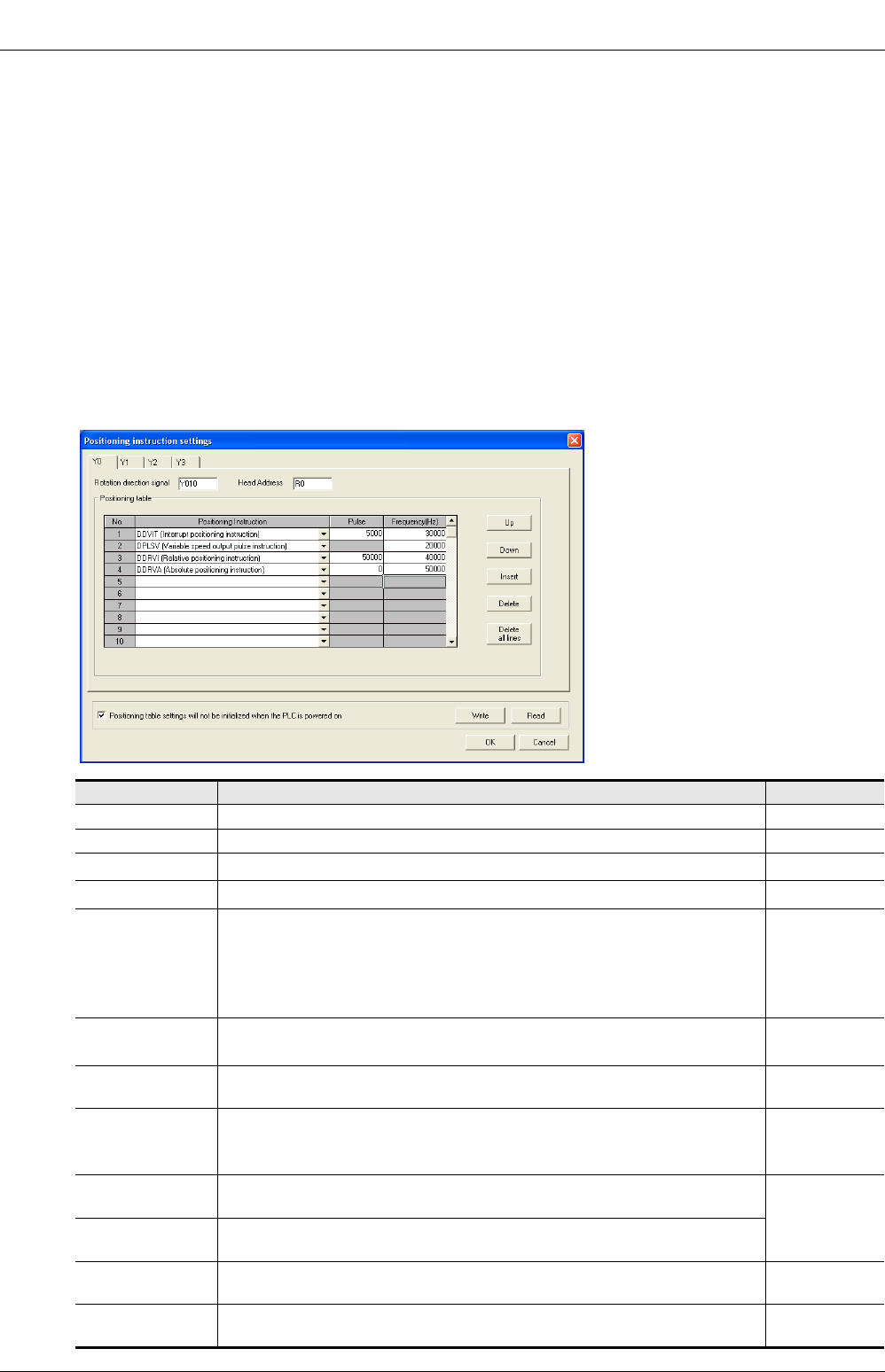
FX
3G
/FX
3U
/FX
3UC
PLC User's Manual - Positioning Control Edition
Built-in Positioning Functions
11 Batch Data Positioning Mode (TBL Instruction)
11.4 Positioning Parameter Setting
B - 148
*1. When the destination for pulse output on a FX3U or FX3UC PLC is a built-in transistor output, the
setting range is 10 to 100,000 Hz.
If an FX3U PLC is used, and if the pulse output destination is a FX3U-2HSY-ADP, the setting range will
be 10 to 200,000 Hz.
*2. Set the creep speed so that the relation with the other speeds is "bias speed ≤ creep speed ≤
maximum speed."
*3. The set interrupt input cannot be simultaneously used for a high-speed counter, input interruption,
pulse catch input, input for the SPD (FNC67) instruction, or for other interrupt inputs of the DVIT
(FNC151) instruction.
*4. Note that this item can only be set if two FX3U-2HSY-ADP adapters are connected to the FX3U PLC.
*5. Only available for FX3U and FX3UC PLCs.
*6. Y002 is not available in 14-point and 24-point type FX3G PLC.
3. Click on the "Individual Setting" button to display the "Positioning instruction setting"
window. In this window, set the positioning table for each pulse output destination device.
Setting item Description of setting Setting range
Y0 Click this tab to set the positioning table for Y000 (pulse output destination). -
Y1 Click this tab to set the positioning table for Y001 (pulse output destination). -
Y2*1 Click this tab to set the positioning table for Y002 (pulse output destination). -
Y3*2 Click this tab to set the positioning table for Y003 (pulse output destination). -
Rotation direction
signal
Set the rotation direction output number.*3
Initial setting: Y010 for Y000 (pulse output destination)
Y011 for Y001 (pulse output destination)
Y012 for Y002 (pulse output destination)
Y013 for Y003*2 (pulse output destination)
Y000 to Y357*6
M0 to M7679
S0 to S4095
Head Address Set the first device number to store the set data (number of pulses, frequency).
Starting from the set device, 1600 points*4 will be occupied. Initial setting: R0
D0 to D6400
R0 to R31168*7
No. Table number
Data can be set for tables 1 to 100. -
Positioning
Instruction
Select a positioning type from the following types:
DDVIT (Interrupt positioning)*5, DPLSV (Variable Speed Pulse Output),
DDRVI (Drive to Increment), DDRVA (Drive to Absolute)
-
Pulse Set the number of pulses to be output to perform the specified type of
positioning operation (instruction). *8
Frequency (Hz) Set the speed (output pulse frequency) to perform the specified type of
positioning operation (instruction).
"Up" button Click this button to move the cursor up by 1 line
(to select the line just above the cursor-positioned line). -
"Down" button Click this button to move the cursor down by 1 line
(to select the line just below the cursor-positioned line). -

FX
3G
/FX
3U
/FX
3UC
PLC User's Manual - Positioning Control Edition
Built-in Positioning Functions
11 Batch Data Positioning Mode (TBL Instruction)
11.4 Positioning Parameter Setting
B - 149
A
Common Items
B
Built-in
Positioning
Functions
Apx.
Example
Connection
*1. Y002 is not available in 14-point and 24-point type FX3G PLC.
*2. Note that this item can only be set if two FX3U-2HSY-ADP adapters are connected to the FX3U PLC.
*3. To use an FX3U-2HSY-ADP, set the rotation direction signal depending on the pulse output destination
device as shown in the following table.
*4. 1200 in the FX3G series PLC.
*5. Only available for FX3U and FX3UC PLCs.
*6. Up to Y000 to Y177 in the FX3G series PLC.
*7. Up to D0 to D6800, R0 to R22800 in the FX3G series PLC.
*8. Refer to the description of the selected instruction (positioning type).
"Insert" button Click this button to insert a line at the specified position. -
"Delete" button Click this button to delete the selected line. -
"Delete All" button Click this button to delete all the data from the positioning table of the selected
pulse output destination device. -
Positioning table
setting will not be
initialized when the
PLC is powered on
If this check box is checked, the positioning data will not be initialized when the
PLC power is turned ON. Enter a check in this check box to retain the
changed data ("pulses" and "frequency" changed by the program, display
module, or HMI) even after power-off and to use the changed data after turning
on the power again. To use this function, set an uninterruptible power supply
type device as the first device.
-
"Write" button
Click this button to write 1600 points*4 of data ("pulses" and "frequency" set on
the positioning table using GX Developer) starting from the first device of the
PLC.
-
"Read" button
Click this button to read out 1600 points*4 of data ("pulses" and "frequency" set
on the positioning table currently used) from the PLC starting from the first
device. At the completion of data reading, the data numbers will appear only if
"Positioning Instruction" is set for the data.
-
Pulse output destination device Rotation direction signal
Y000 Y004
Y001 Y005
Y002 Y006
Y003 Y007
Positioning type Refer to
DDVIT (Interrupt positioning) Chapter 9
DPLSV (Variable Speed Pulse Output) Chapter 10
DDRVI (Drive to Increment) Section 8.2
DDRVA (Drive to Absolute) Section 8.3
Setting item Description of setting Setting range

FX
3G
/FX
3U
/FX
3UC
PLC User's Manual - Positioning Control Edition
Built-in Positioning Functions
11 Batch Data Positioning Mode (TBL Instruction)
11.4 Positioning Parameter Setting
B - 150
4Transfer the parameters (+ sequence program) to the PLC.
1. Select "Online" from the tool menu, and then select "Write to PLC". The "Write to PLC"
window will appear.
*1. For Ver. 8.13P to 8.24A of GX Developer, the PLC type is FX3UC.
2. Enter a check in the "PLC parameter" check box, and then click the "Execute" button.
The selected parameter data will be transferred to the PLC. When the PLC is started (enters the RUN mode),
the transferred parameter data will be enabled. If the communication conditions set on the "PLC system(2)"
screen are changed, be sure to power the PLC OFF, and then ON again.
*1
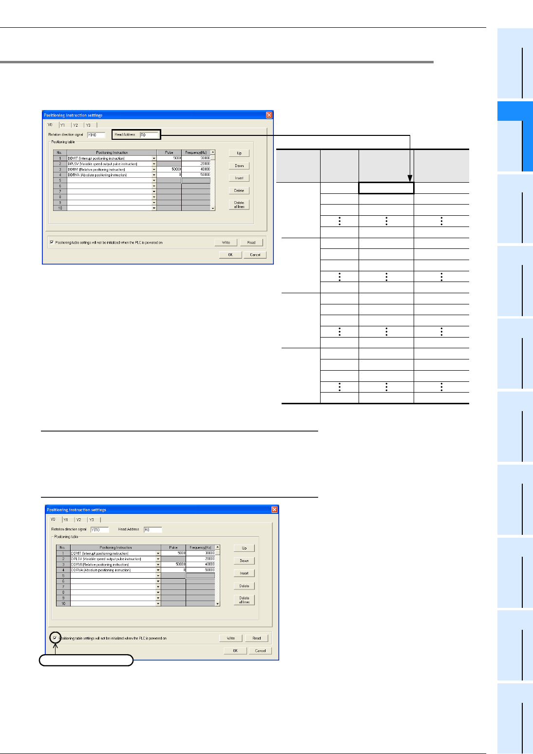
FX
3G
/FX
3U
/FX
3UC
PLC User's Manual - Positioning Control Edition
Built-in Positioning Functions
11 Batch Data Positioning Mode (TBL Instruction)
11.4 Positioning Parameter Setting
B - 151
A
Common Items
B
Built-in
Positioning
Functions
Apx.
Example
Connection
11.4.2 Changing of Set Positioning Parameters (Number of Pulses and Frequency)
The "pulses" and "frequency" set by the positioning parameters in a positioning table will be stored in the
devices starting from the specified first device as shown below. The set "pulses" and "frequency" can be
changed using a display module or HMI.
Caution:
If "positioning type" is set to "DPLSV (Variable Speed Pulse Output)", the "frequency (Hz)" value set on the
screen will be stored as the set number of pulses, and the device for "frequency" will be "K0".
To use the "pulses" and "frequency" changed by a display module or HMI even after turning the
power OFF and then ON again:
To use the "pulses" and "frequency" changed
by a display module or HMI even after turning
the power OFF and then ON again, enter a
check in the "Positioning table settings will not
be initialized when the PLC is powered on"
check box in the "Positioning instruction
Setting" window of the positioning parameters.
To use this function, use the uninterruptible
power supply type devices.
If this function is not set, the data set by the
positioning parameters will be initialized.
Frequency
If the Head Address is set to "R0":
Pulse
output
destination
device
Positioning
table No.
Number of
pulses
R1,R0 R3,R2
R5,R4 R7,R6
R9,R8 R11,R10
R397,R396 R399,R398
R401,R400 R403,R402
R405,R404 R407,R406
R409,R408 R411,R410
R797,R796 R799,R798
R801,R800 R803,R802
R805,R804 R807,R806
R809,R808 R811,R810
R1197,R1196 R1199,R1198
R1201,R1200 R1203,R1202
1
2
3
100
1
2
3
100
1
2
3
100
1
2
3
100
Y000
Y001
Y002
Y003
R1205,R1204
R1209,R1208
R1597,R1596
R1207,R1206
R1211,R1210
R1599,R1598
Enter a check.
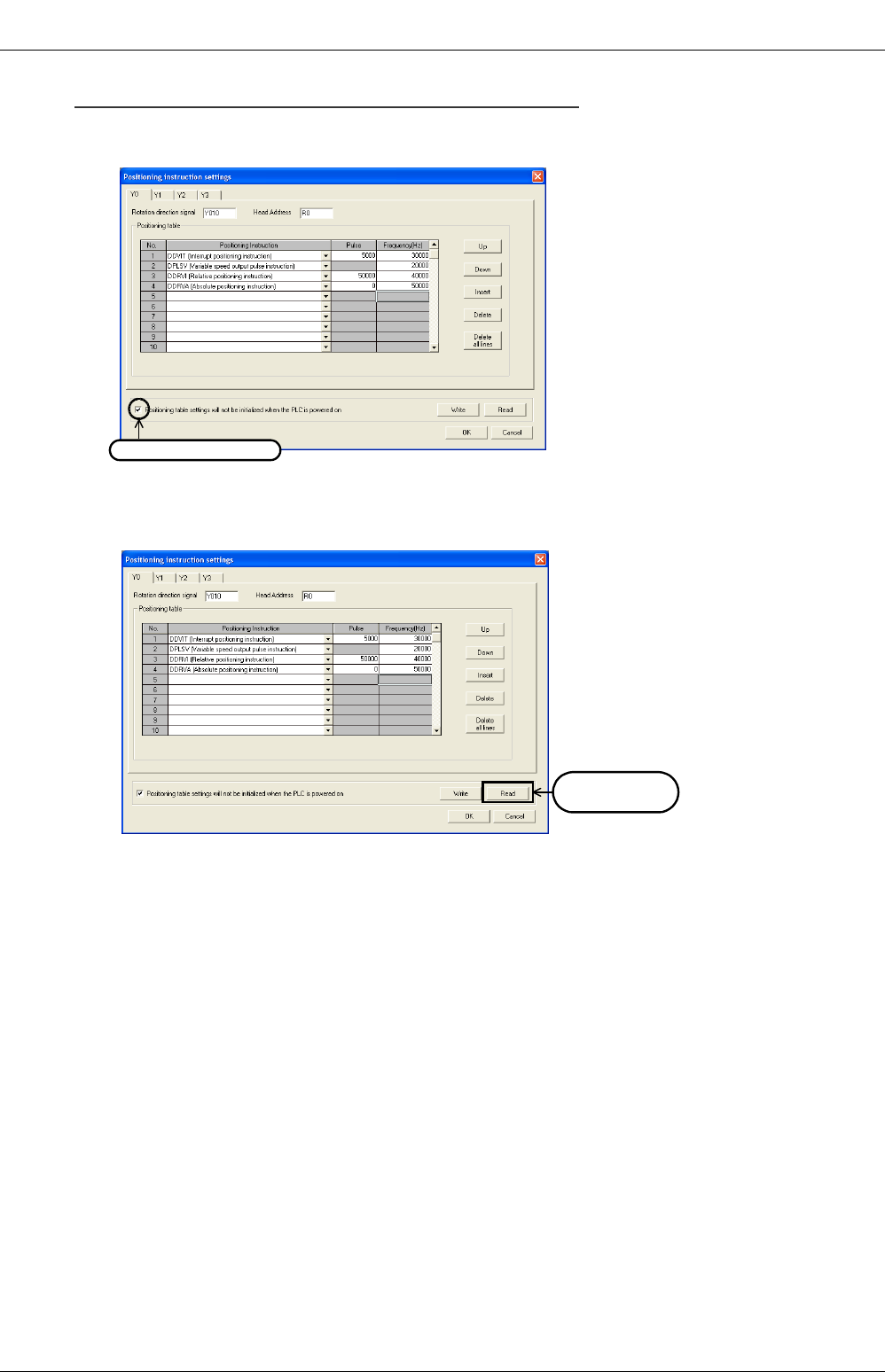
FX
3G
/FX
3U
/FX
3UC
PLC User's Manual - Positioning Control Edition
Built-in Positioning Functions
11 Batch Data Positioning Mode (TBL Instruction)
11.4 Positioning Parameter Setting
B - 152
To read out and store the "pulse" and "frequency" changed by a display module or HMI:
1) In the "Positioning instruction setting" window of the positioning parameters, enter a check in the
"Positioning table settings will not be initialized when the PLC is powered on" check box.
2) Click on the "Read" button to read out the set data ("pulse" and "frequency") from the connected main
unit.
This is exclusively for the positioning table number with the positioning type specified.
3) At the completion of register data reading, the data file will be stored.
Enter a check.
Click the
"Read" button.

FX
3G
/FX
3U
/FX
3UC
PLC User's Manual - Positioning Control Edition
Built-in Positioning Functions
12 Examples of Programs
B - 153
A
Common Items
B
Built-in
Positioning
Functions
Apx.
Example
Connection
12. Examples of Programs
Assuming that the MELSERVO Series 1-axis servo amplifier is used for control, this chapter shows various
examples of programs.
For the connection examples of MELSERVO-C, -J2(S), -H, and -J3 Series, refer to the following chapters and
manuals.
→ Refer to Chapter 3 and the examples of connection shown in the Appendix.
→ Refer to the manual of your servo amplifier.
Operation Instruction
Examples of programs Description
of
instruction
Relay ladder
program
Step ladder
program
Mechanical zero
return
DOG Search Zero
Return DSZR(FNC150) Subsection 12.2.1 Subsection 12.3.1 Section 6.2
Absolute position
detection
Reading of current
ABS value ABS(FNC155) Section 12.5 - Chapter 7
1-speed positioning Drive to Increment DRVI(FNC158) Subsection 12.2.1 Subsection 12.3.1 Section 8.2
Drive to Absolute DRVA(FNC159) Subsection 12.2.1 Subsection 12.3.1 Section 8.3
Batch data positioning mode TBL(FNC152) Section 12.4 - Chapter 11
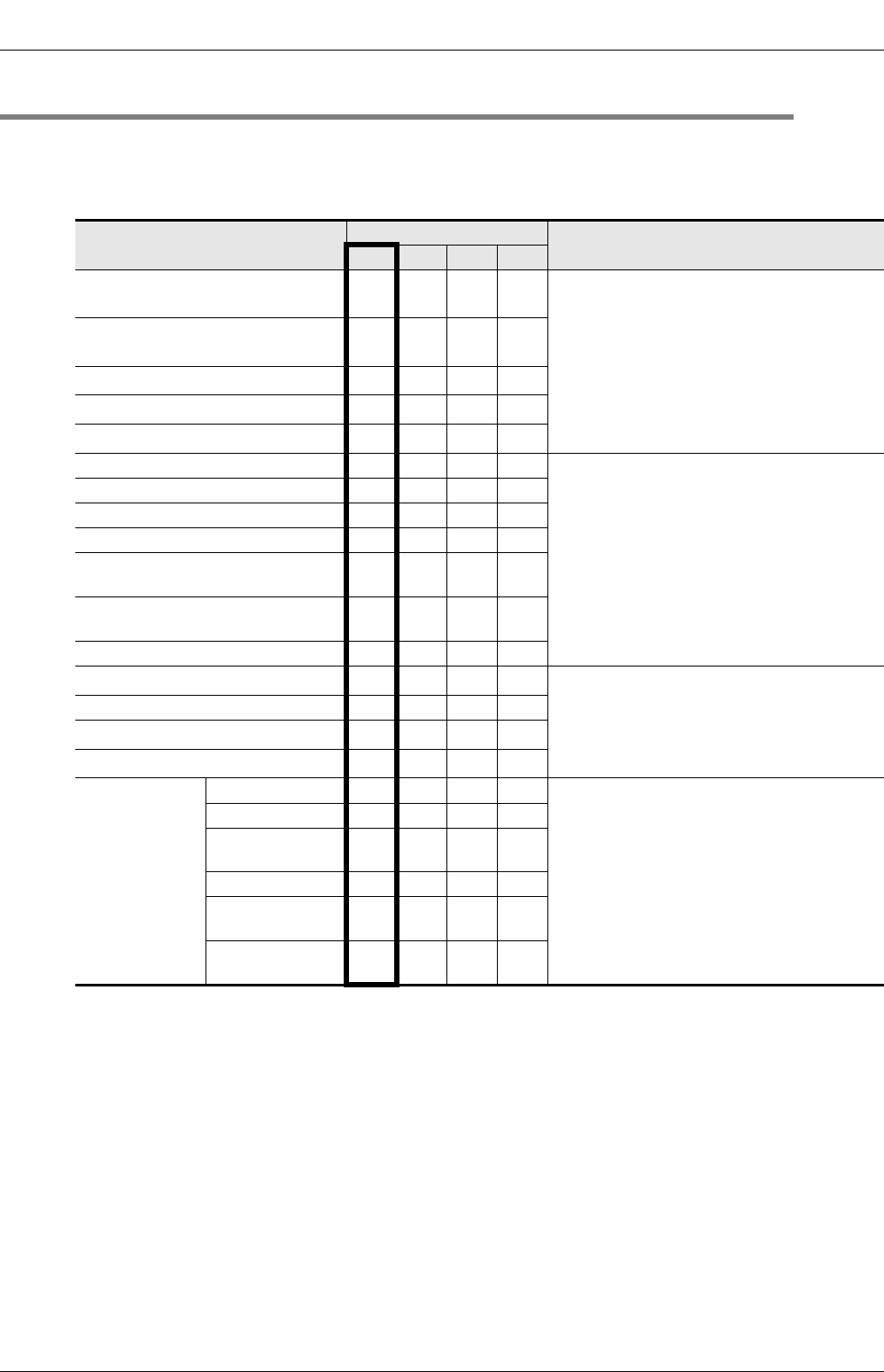
FX
3G
/FX
3U
/FX
3UC
PLC User's Manual - Positioning Control Edition
Built-in Positioning Functions
12 Examples of Programs
12.1 Input/Output Assignment
B - 154
12.1 Input/Output Assignment
The programs shown in this chapter use 1 axis for Y000 (pulse output destination device). If other pulse
output destination device are used, change various device numbers when reading the description.
Note that Y003 (pulse output destination device) can be used only if two FX3U-2HSY-ADP adapters are
connected to the FX3U PLC.
*1. To use the "forward rotation pulse train" signal and "reverse rotation pulse train" signal of a FX3U-
2HSY-ADP, change the name of this signal to "forward rotation pulse train" signal when reading the
description.
*2. To use the "forward rotation pulse train" signal and "reverse rotation pulse train" signal of a FX3U-
2HSY-ADP, change the name of this signal to "reverse rotation pulse train" signal when reading the
description.
*3. If an FX3UC PLC below Ver.2.20 is used, exchange the direction signal output number with the CLEAR
signal output number.
*4. If the absolute position detection system is used, and if the DSZR instruction and ZRN instruction are
not used for the first zero return, this signal is not needed. To use the absolute position detection
system, refer to the following chapter and manual.
→ Refer to Chapter 7 and the manual of your servo amplifier.
*5. To use the ZRN instruction for zero return, assign the input number of the near-point signal (DOG) to
the zero-phase signal. This is needed since the ZRN instruction will not use the zero-phase signal.
Signal Input/output number Connected to
Y000 Y001 Y002 Y003
Pulse train*1
(pulse output destination) Y000 Y001 Y002 Y003
Connected to MELSERVO Series
servo amplifier.
Direction*2, *3
(rotation direction signal) Y004 Y005 Y006 Y007
CLEAR signal*3, *4 Y020 Y024 Y030 Y034
Zero-phase signal*4, *5 X004 X005 X006 X007
"Servo ready" signal*6 X014 X015 X016 X017
Immediate stop command X020 X040 X050 X070
Connected to external switches.
Zero return command X021 X041 X051 X071
Jog (+) command X022 X042 X052 X072
Jog (-) command X023 X043 X053 X073
Forward rotation positioning
command X024 X044 X054 X074
Reverse rotation positioning
command X025 X045 X055 X075
Stop command X030 X034 X060 X064
Near-point signal (DOG)*4, *5 X010 X011 X012 X013
Connected to sensors and limit switches.
Interrupt signal X000 X001 X002 X003
Forward rotation limit (LSF)*7 X026 X046 X056 X076
Reverse rotation limit (LSR)*7 X027 X047 X057 X077
To use absolute
position detection
system
ABS(bit0) X031 X035 X061 X065
Connected to Mitsubishi MELSERVO Series
servo amplifier
(MR-J2,MR-J2S, MR-J3, MR-H)
ABS(bit1) X032 X036 X062 X066
"Send data ready"
signal X033 X037 X063 X067
Servo-ON signal Y021 Y025 Y031 Y035
"ABS data transfer
mode" signal Y022 Y026 Y032 Y036
"ABS data
request" signal Y023 Y027 Y033 Y037
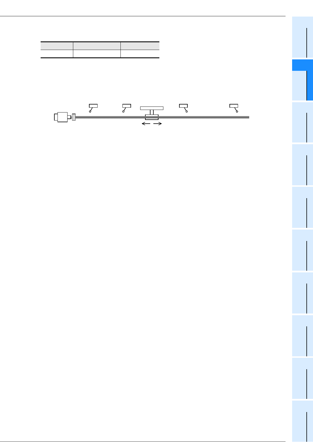
FX
3G
/FX
3U
/FX
3UC
PLC User's Manual - Positioning Control Edition
Built-in Positioning Functions
12 Examples of Programs
12.1 Input/Output Assignment
B - 155
A
Common Items
B
Built-in
Positioning
Functions
Apx.
Example
Connection
*6. To use pin 3 of the CN1 connector of the MR-CA servo amplifier for the "servo ready" signal, set
parameter 21 as follows:
*7.
To ensure safety, use a forward rotation limit switch and reverse rotation limit switch on both sides: the
PLC side and the servo amplifier side.
Note that the limit switches on the PLC side should be activated slightly earlier than the limit switches
on the servo amplifier side.
Series Parameter number Setting value
MR-C 21 020
Reverse rotation limit 2
(Servo amplifier side)
Reverse rotation limit 1
(Programmable controller side)
Forward rotation limit 2
(Servo amplifier side)
Forward rotation limit 1
(Programmable controller side)
Reverse rotation Forward rotation
Servo motor
LSFLSR
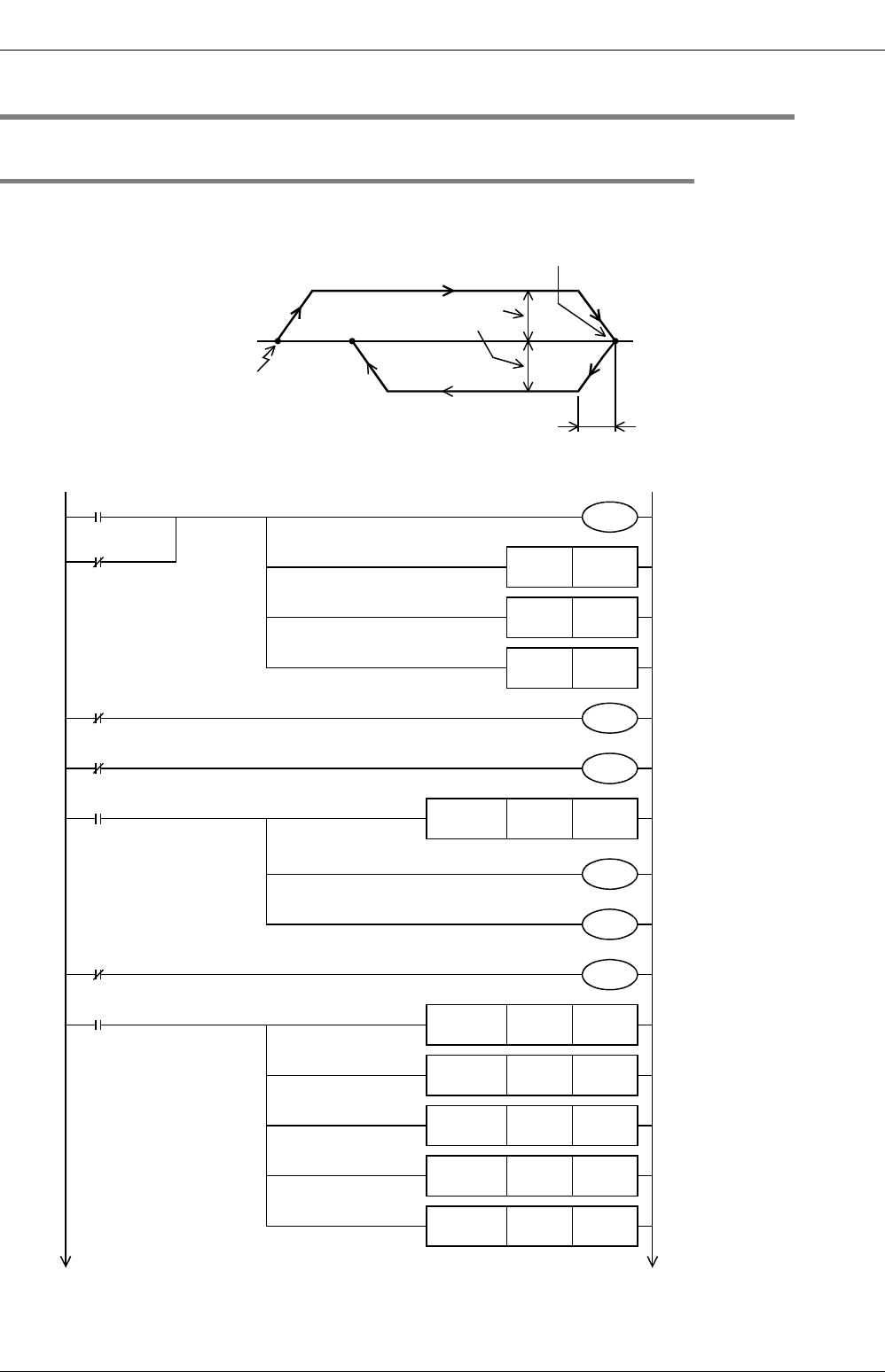
FX
3G
/FX
3U
/FX
3UC
PLC User's Manual - Positioning Control Edition
Built-in Positioning Functions
12 Examples of Programs
12.2 Programs for Forward/Reverse Rotation (Relay Ladder Program)
B - 156
12.2 Programs for Forward/Reverse Rotation (Relay Ladder Program)
12.2.1 Example Program
Positioning operation will be performed using the absolute positioning method shown in the following chart:
→ For details on input/output assignment, refer to Section 12.1.
The following program is a relay ladder program.
*1. If the initial values (maximum speed, acceleration/deceleration time, zero return speed, creep speed)
can be used, it is not necessary to create the program.
→ For the related devices, refer to Section 4.1 to Section 4.4.
100
Origin
Output pulse frequency:
100,000 Hz
Acceleration/deceleration time:
100 ms
500,000
X020 Stops outputting Y000
pulses. (Immediate stop)
Refer to Subsection 4.7.2.
Enables the origin return
operation with CLEAR signal
outputting function. (CLEAR
signal: Y020)
Performs origin return in the
forward rotation direction.
M8349
M8341
X014
Immediate stop
Servo ready
M8000
Initial pulse
M8342
M8002 D8343K100000
FNC 12
DMOV
D8345K1000
FNC 12
MOV
D8346K50000
FNC 12
DMOV
D8348K100
FNC 12
MOV
D8349K100
FNC 12
MOV
Sets the maximum speed.
100,000(Hz)
→
D8344,D8343
Sets the origin return speed.
50,000(Hz)
→
D8347,D8346
Sets the acceleration time.
100(ms)
→
D8348
Sets the deceleration time.
100(ms)
→
D8349
Sets the creep speed.
1,000(Hz)
→
D8345
M8000
RUN monitor
RUN monitor
*1
*1
*1
*1
M10RST
M12RST
M13RST
M8343
M8344
X026
Forward rotation limit
X027
Reverse rotation limit
Resets the "origin return
completion" flag.
Resets the "forward rotation
positioning completion" flag.
Resets the "reverse rotation
positioning completion" flag.
Forward rotation limit(Y000)
Reverse rotation limit(Y000)
*1
D8464H0020
FNC 12
MOVP
M8464
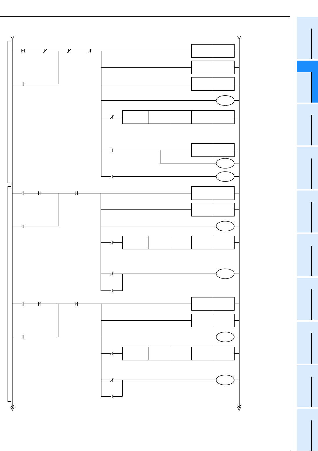
FX
3G
/FX
3U
/FX
3UC
PLC User's Manual - Positioning Control Edition
Built-in Positioning Functions
12 Examples of Programs
12.2 Programs for Forward/Reverse Rotation (Relay Ladder Program)
B - 157
A
Common Items
B
Built-in
Positioning
Functions
Apx.
Example
Connection
*1. The maximum transfer distance for each jogging operation is ±999,999 pulses (pulse output range of
FNC158 (DRVI) instruction). To move the workpiece further, execute the JOG command again.
Zero
return
M8348
Positioning
being
performed
(Y000)
M10RST
M12RST
M13RST
X021 M101
Normal
end of
zero
return
M100
Zero return being
performed
M102
Abnormal
end of
zero
return
M100
Y004Y000X004X010
FNC 150
DSZR
M8029
"Execution
completion" flag
M10SET
M101
M102
M8329
Abnormal
end
JOG
(+)
M8348 M12RST
X022 M104
Completes
the JOG(+)
operation.
Positioning
being
performed
(Y000)
M13RST
M103
Y004Y000K30000K999999
FNC 158
DDRVI
Near-point
signal
Zero-
phase
signal
Pulse
output
destination
number
Rotation
direction
signal
Number of
output pulses
(maximum value
in "+" direction)
Output
pulse
frequency
Pulse
output
destination
number
Rotation
direction
signal
M103
JOG(+) operation is
being performed.
X022
JOG(+)
M104
M8329
Abnormal
end
Zero return
Jogging operation
JOG
(-)
M8348 M12RST
X023 M106
Completes
the JOG(-)
operation.
Positioning
being
performed
(Y000)
M13RST
M105
Y004Y000K30000K-999999
FNC 158
DDRVI
Number of
output pulses
(maximum value
in "-" direction)
Output
pulse
frequency
Pulse
output
destination
number
Rotation
direction
signal
M105
JOG(-) operation is
being performed.
X023
JOG(-)
M106
M8329
Abnormal
end
X030
Stop
command
X030
Stop
command
X030
Stop
command
*1
*1
Resets the "zero
return completion"
flag.
Resets the "forward
rotation positioning
completion" flag.
Resets the "reverse
rotation positioning
completion" flag.
Zero return is being
performed.
Zero return instruction
with DOG search
function
(CLEAR signal: Y020)
Resets the "forward
rotation positioning
completion" flag.
Resets the "reverse
rotation positioning
completion" flag.
JOG(+) operation is
being performed.
Performs the jogging
operation in the "+"
direction using the
drive to Increment
instruction.
(Y004=ON)
"Zero return
completion" flag
Normal end of zero
return
Abnormal end of
zero return
Completes the
JOG(+) operation.
Resets the "forward
rotation positioning
completion" flag.
Resets the "reverse
rotation positioning
completion" flag.
JOG(-) operation is
being performed.
Performs the jogging
operation in the "-"
direction using the
drive to Increment
instruction.
(Y004=OFF)
Completes the
JOG(-) operation.
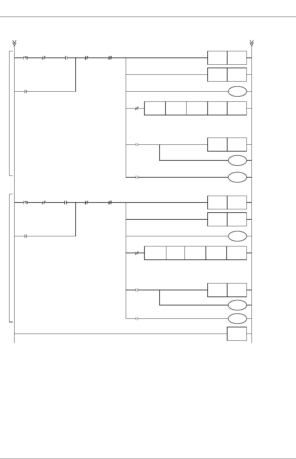
FX
3G
/FX
3U
/FX
3UC
PLC User's Manual - Positioning Control Edition
Built-in Positioning Functions
12 Examples of Programs
12.2 Programs for Forward/Reverse Rotation (Relay Ladder Program)
B - 158
Position-
ing in
forward
rotation
direction
M8348
Position-
ing
operation
being
performed
X024
M107
Positioning operation being
performed in forward rotation
direction
M107
M8029
"Execution
completion"
flag
M108
M109
M8329
Abnormal end
M10
"Zero
return
compl-
etion"
flag
M108
Normal
end of
positioning
in forward
rotation
direction
M109
Abnormal
end of
positioning
in forward
rotation
direction
Positioning in forward rotation direction
M110
M8029
"Execution
completion"
flag
M111
M112
M8329
Abnormal end
Position-
ing in
reverse
rotation
direction
M8348
Position-
ing
operation
being
performed
(Y000)
X025
M110
Positioning operation being
performed in reverse
rotation direction
M10
"Zero
return
compl-
etion"
flag
M111
Normal
end of
positioning
in reverse
rotation
direction
M112
Abnormal
end of
positioning
in reverse
rotation
direction
Positioning in reverse rotation direction
X030
Stop
command
M12RST
M13RST
Y004Y000K100000K500000
FNC 159
DDRVA
M12SET
M12RST
M13RST
Y004Y000K100000K100
M13SET
END
X030
Stop
command
FNC 159
DDRVA
Designation
of absolute
position
Output
pulse
frequency
Pulse
output
destination
number
Rotation
direction
signal
Designation
of absolute
position
Output
pulse
frequency
Pulse
output
destination
number
Rotation
direction
signal
"Forward rotation
positioning
completion" flag
"Reverse rotation
positioning
completion" flag
Positioning
operation being
performed in
forward rotation
direction
Moves to absolute
position 500000
using the absolute
positioning
instruction.
(Y004=ON)
"Forward rotation
positioning
completion" flag
"Forward rotation
positioning normal
end" flag
"Forward rotation
positioning
abnormal end" flag
"Forward rotation
positioning
completion" flag
"Reverse rotation
positioning
completion" flag
Positioning
operation being
performed in
reverse rotation
direction
Moves to absolute
position 100 using
the absolute
positioning
instruction.
(Y004=OFF)
"Reverse rotation
positioning
completion" flag
"Reverse rotation
positioning normal
end" flag
"Reverse rotation
positioning
abnormal end" flag
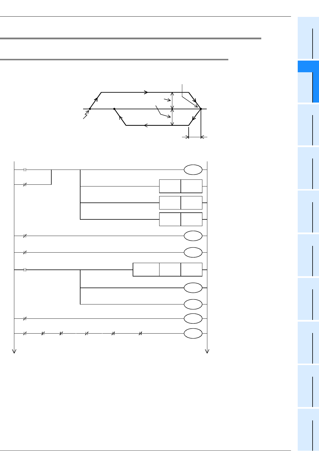
FX
3G
/FX
3U
/FX
3UC
PLC User's Manual - Positioning Control Edition
Built-in Positioning Functions
12 Examples of Programs
12.3 Programs for Forward/Reverse Rotation (Step Ladder (STL) Program)
B - 159
A
Common Items
B
Built-in
Positioning
Functions
Apx.
Example
Connection
12.3 Programs for Forward/Reverse Rotation (Step Ladder (STL) Program)
12.3.1 Example Program
Positioning operation will be performed using the absolute positioning method as shown in the following chart:
→ For details on input/output assignment, refer to Section 12.1.
The following program uses the step ladder (STL) instruction.
100
Origin
Output pulse frequency:
100,000 Hz
Acceleration/deceleration time:
100 ms
500,000
Enables the zero return
operation with CLEAR signal
outputting function. (CLEAR
signal: Y020)
Performs zero return in the
forward rotation direction.
Operation is stopped.
M8000
M8342
M5
S0
Zero
return
S10 S11 S12 S13 M8349
JOG
(+)
JOG
(-)
Positioning
in forward
rotation
direction
Positioning in
reverse
rotation
direction
Stoppage of Y0
pulse
outputting
operation
M8000
RUN monitor
RUN monitor
X020
Stops outputting Y000 pulses.
(Immediate stop) Refer to
Section 4.7.2.
M8349
X014
Immediate stop
Servo ready
M10RST
M12RST
M13RST
M8343
M8344
X026
Forward rotation limit
X027
Reverse rotation limit
Resets the "zero return
completion" flag.
Resets the "forward rotation
positioning completion" flag.
Resets the "reverse rotation
positioning completion" flag.
Reverse limit (Y000)
M8341
D8464H0020
FNC 12
MOVP
M8464
Forward limit (Y000)
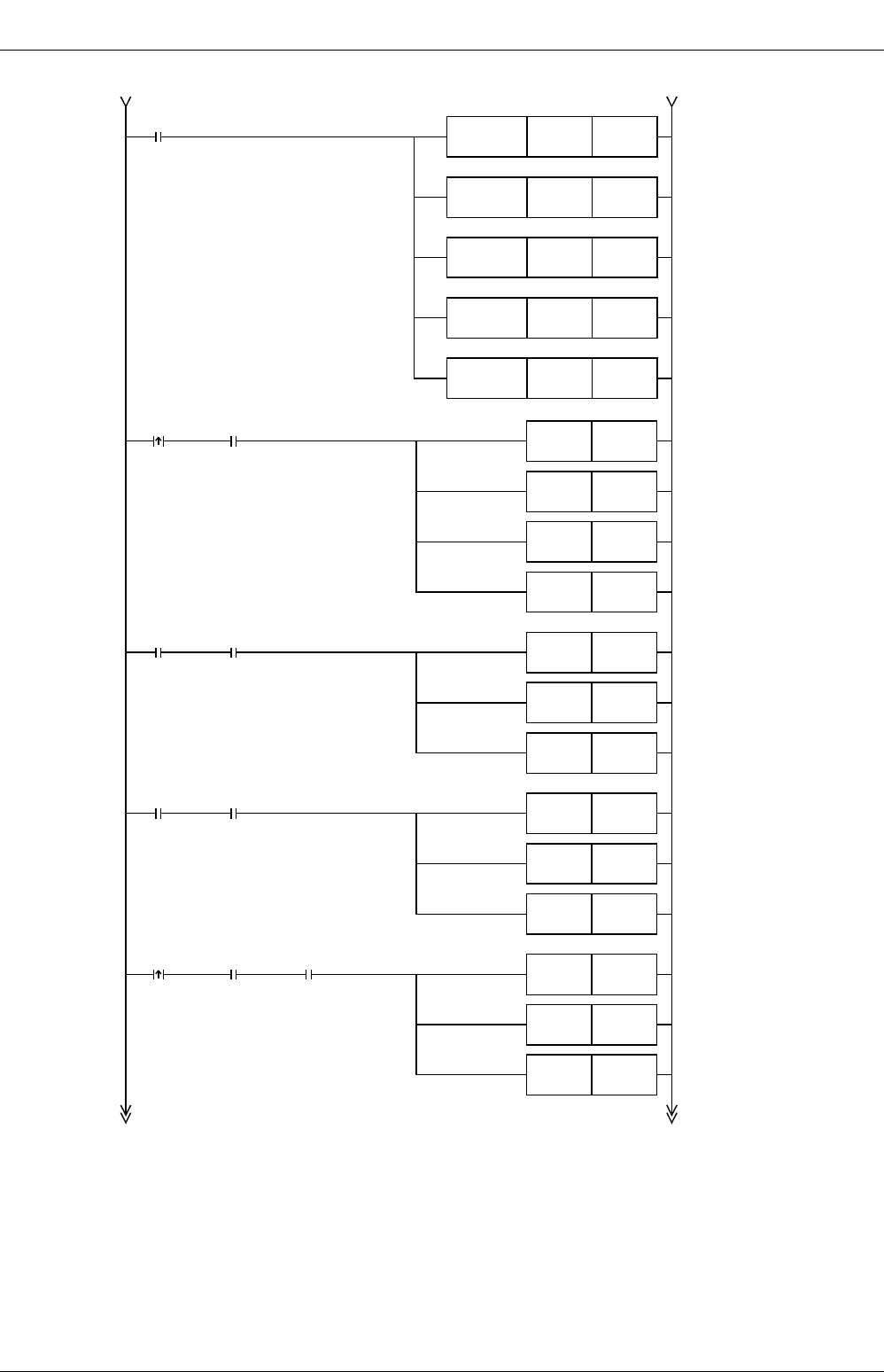
FX
3G
/FX
3U
/FX
3UC
PLC User's Manual - Positioning Control Edition
Built-in Positioning Functions
12 Examples of Programs
12.3 Programs for Forward/Reverse Rotation (Step Ladder (STL) Program)
B - 160
*1. If the initial values (maximum speed, acceleration/deceleration time, zero return speed, creep speed)
can be used, it is not necessary to create the program.
→ For the related devices, refer to Section 4.1 to Section 4.4.
*2. The maximum transfer distance for each jogging operation is ±999,999 pulses (pulse output range of
FNC158 (DRVI) instruction). To move the workpiece further, execute the JOG command again.
Zero
return
M5
Operation
stopped
X022
JOG(+)
M5
Operation
stopped
Positioning
in forward
rotation
direction
M5
Operation
stopped
M10
"Zero return
completion" flag
X023
JOG(-)
M5
Operation
stopped
M10RST
M12RST
M13RST
S0SET
M12RST
M13RST
S10SET
M12RST
M13RST
S12SET
M12RST
M13RST
S11SET
X021
X024
*2
*2
Initial pulse
M8002 D8343K100000
FNC 12
DMOV
D8345K1000
FNC 12
MOV
D8346K50000
FNC 12
DMOV
D8348K100
FNC 12
MOV
D8349K100
FNC 12
MOV
*1
*1
*1
*1
*1
Resets the "zero return
completion" flag.
Resets the "forward rotation
positioning completion" flag.
Resets the "reverse rotation
positioning completion" flag.
Enters the zero return state
(S0).
Resets the "forward rotation
positioning completion" flag.
Resets the "reverse rotation
positioning completion" flag.
Resets the "forward rotation
positioning completion" flag.
Resets the "reverse rotation
positioning completion" flag.
Resets the "forward rotation
positioning completion" flag.
Resets the "reverse rotation
positioning completion" flag.
Enters the JOG(+) state
(S10).
Enters the JOG(-) state
(S11).
Enters the forward rotation
positioning state (S12).
Sets the maximum speed.
100,000(Hz)
→
D8344,D8343
Sets the zero return speed.
50,000(Hz)
→
D8347,D8346
Sets the acceleration time.
100(ms)
→
D8348
Sets the deceleration time.
100(ms)
→
D8349
Sets the creep speed.
1,000(Hz)
→
D8345
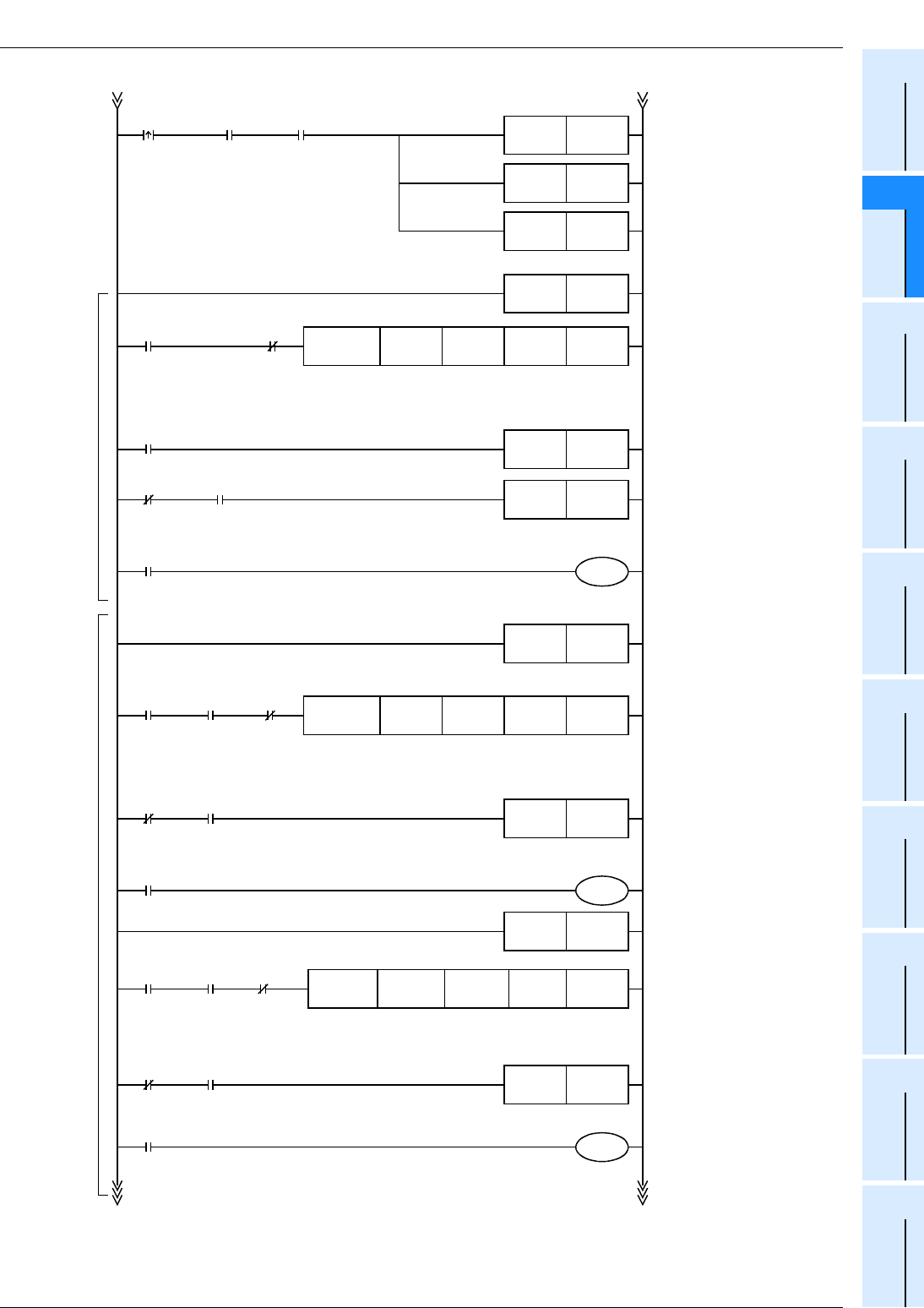
FX
3G
/FX
3U
/FX
3UC
PLC User's Manual - Positioning Control Edition
Built-in Positioning Functions
12 Examples of Programs
12.3 Programs for Forward/Reverse Rotation (Step Ladder (STL) Program)
B - 161
A
Common Items
B
Built-in
Positioning
Functions
Apx.
Example
Connection
*3. To stop the positioning operation, be sure to insert the stop contact before the positioning instruction so that STL
instruction cannot be turned off (reset) until the "pulse output monitor" flag (M8340 (for Y000)) is turned off.
*4. To prevent simultaneous activation of positioning instructions, the instruction activation timing should be delayed by 1
scan time.
M8340
Y000
Outputting
M50
Waiting for
1 scan time
X022
JOG(+)
M51
Zero return
Zero return instruction with
DOG search function
(CLEAR signal: Y020)
"Zero return completion" flag
End of zero return
(Self-reset)
Ends the JOG(+) operation.
(Self-reset)
Performs the jogging
operation in the "-" direction
using the drive to Increment
instruction.(Y004=OFF)
Ends the JOG(-) operation.
(Self-reset)
Performs the jogging
operation in the "+" direction
using the drive to Increment
instruction.(Y004=ON)
S0STL
Y004Y000
M10SET
S0RST
S10RST
M50
Waiting for
1 scan time
M8029
"Execution completion" flag
X004X010
FNC 150
DSZR
Rotation
direction
signal
Pulse
output
destination
number
Zero-
phase
signal
Near-
point
signal
M50
S10STL
Y004Y000K30000K999999
FNC 158
DDRVI
Rotation
direction
signal
Pulse
output
destination
number
Output
pulse
frequency
Number of output
pulses (maximum
value in "+"
direction)
M51
S11STL JOG(-)
Y004Y000K30000K-999999
FNC 158
DDRVI
Rotation
direction
signal
Pulse
output
destination
number
Output
pulse
frequency
Number of
output pulses
(maximum value
in "-" direction)
S11RST
M52
Waiting for 1 scan time
M8000
RUN monitor
M8340
Y000
Outputting
M51
Waiting for 1 scan time
Waiting
for 1 scan
time
M8000
RUN monitor
X23
JOG(-)
M52
Waiting for
1 scan time
M8340
Y000
Outputting
M52
Waiting for
1 scan time
M8000
RUN monitor
*4
*4
*4
Zero returnJogging operation
JOG(+)
Waiting for 1 scan time
Waiting for 1 scan time
X030
*3
Stop
command
X030
*3
Stop
command
X030
*3
Stop
command
M5
Operation
stopped
M10
"Zero return
completion" flag
Resets the "forward rotation
positioning completion" flag.
Resets the "reverse rotation
positioning completion" flag.
Enters the reverse rotation
positioning state (S13).
M12RST
M13RST
S13SET
Positioning
in reverse
rotation
direction
X025
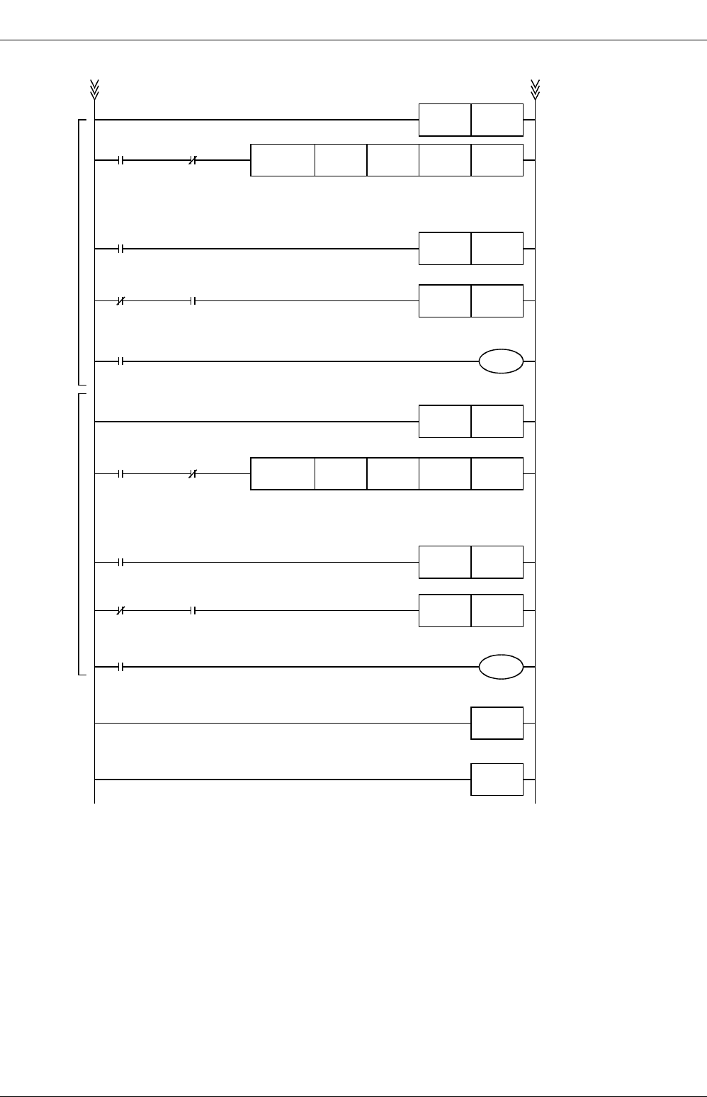
FX
3G
/FX
3U
/FX
3UC
PLC User's Manual - Positioning Control Edition
Built-in Positioning Functions
12 Examples of Programs
12.3 Programs for Forward/Reverse Rotation (Step Ladder (STL) Program)
B - 162
*5. To stop the positioning operation, be sure to insert the stop contact before the positioning instruction
so that the STL instruction cannot be turned off (reset) until the "pulse output monitor" flag (M8340 (for
Y000)) is turned off.
*6. To prevent simultaneous activation of positioning instructions, the instruction activation timing should
be delayed by 1 scan time.
M8340
Y000
Outputting
M53
Waiting for 1 scan time
Moves to absolute position
500000 using the drive to
Absolute instruction.
(Y004=ON)
"Forward rotation positioning
completion" flag
Ends the positioning
operation in the forward
rotation direction.
(Self-reset)
S12STL
Y004Y000
M12SET
S12RST
M53
Waiting for
1 scan time
M8029
"Execution completion" flag
K100000K500000
FNC 159
DDRVA
Rotation
direction
signal
Pulse
output
destination
number
Output
pulse
frequency
Designation
of absolute
position
M53
M13SET
M54
M8000
RUN monitor
M8340
Y000
Outputting
M54
Waiting for 1 scan time
*6
*6
Positioning in forward rotation directionPositioning in reverse rotation direction
S13RST
RET
END
Ends the positioning
operation in the reverse
rotation direction.
(Self-reset)
S13STL
Positioning in reverse rotation
direction
Y004Y000
M54
Waiting for
1 scan
time
K100000K100
FNC 159
DDRVA
Rotation
direction
signal
Pulse
output
destination
number
Output
pulse
frequency
Designation
of absolute
position
"Reverse rotation positioning
completion" flag
Moves to absolute position
100 using the drive to
Absolute instruction.
(Y004=OFF)
M8029
"Execution completion" flag
M8000
RUN monitor
Positioning in forward rotation
direction
Waiting for 1 scan time
Waiting for 1 scan time
X030
*5
Stop
command
X030
*5
Stop
command
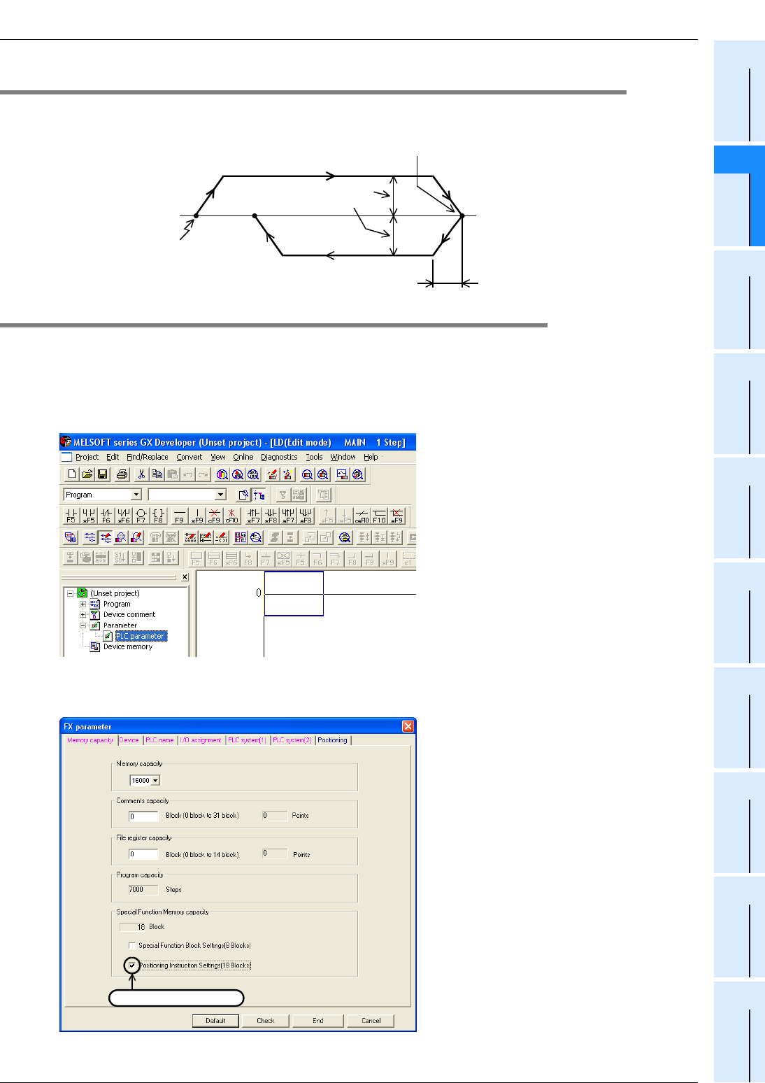
FX
3G
/FX
3U
/FX
3UC
PLC User's Manual - Positioning Control Edition
Built-in Positioning Functions
12 Examples of Programs
12.4 Positioning Using Batch Setting Method
B - 163
A
Common Items
B
Built-in
Positioning
Functions
Apx.
Example
Connection
12.4 Positioning Using Batch Setting Method
Positioning operation will be performed using the absolute positioning method as shown in the following chart:
→ For details on input/output assignment, refer to Section 12.1
12.4.1 Setting Using GX Developer
This section describes how to set the positioning parameters using GX Developer Ver.8.23Z.
1On the project tree displayed on the left side of the screen, double-click on
"Parameter" and then "PLC parameter".
If the project tree is not displayed on the screen, click on "View" in the menu bar, and then click on "Project Data
List".
2Click on "Memory Capacity", and then enter a check in the "Positioning
Instruction settings" check box.
*1. 9,000 steps are needed to set the positioning data. If there is not enough capacity for programming,
set the "memory capacity" to 16,000 steps.
100
Origin
Output pulse frequency:
100,000 Hz
Acceleration/deceleration time:
100 ms
500,000
Enter a check.
*1
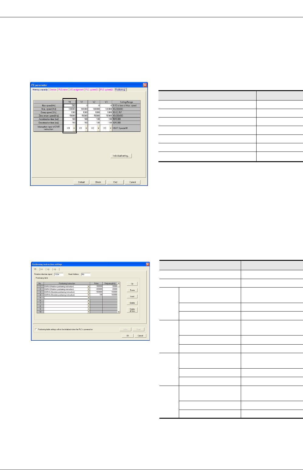
FX
3G
/FX
3U
/FX
3UC
PLC User's Manual - Positioning Control Edition
Built-in Positioning Functions
12 Examples of Programs
12.4 Positioning Using Batch Setting Method
B - 164
3Click on the "Positioning" tab, and then set Y000 (pulse output destination)
as follows.
Before clicking on the "Positioning" tab, click on the "Memory Capacity" tab, and then enter a check in the
"Positioning" check box. After entering a check, positioning data can be set.
After entering a check, positioning data can be set. Use the FX3U/FX3UC PLC of Ver.2.20 or later or FX3G PLC
to use "Positioning".
*1. Only available for FX3U and FX3UC PLCs.
4Click on the "Individual setting" button. The "Individual setting" setting
window will appear. In this window, click on the "Y000" tab to display the
positioning table for Y000 (pulse output destination). Set the data in the
positioning table as follows:
Setting item Setting value
Bias speed (Hz) 500
Maximum speed (Hz) 100,000
Creep speed (Hz) 1000
Zero return speed (Hz) 50,000
Acceleration time (ms) 100
Deceleration time (ms) 100
Interrupt input for DVIT instruction*1 X000
Setting item Setting value
Rotation direction signal Y004
First device R0
No. 1
Positioning type DDRVI
(drive to increment)
Number of pulses (PLS) 999,999
Frequency (Hz) 30,000
No. 2
Positioning type DDRVI
(drive to increment)
Number of pulses (PLS)-999,999
Frequency (Hz) 30,000
No. 3
Positioning type DDRVA
(drive to absolute)
Number of pulses (PLS) 500,000
Frequency (Hz) 100,000
No. 4
Positioning type DDRVA
(drive to absolute)
Number of pulses (PLS) 100
Frequency (Hz) 100,000
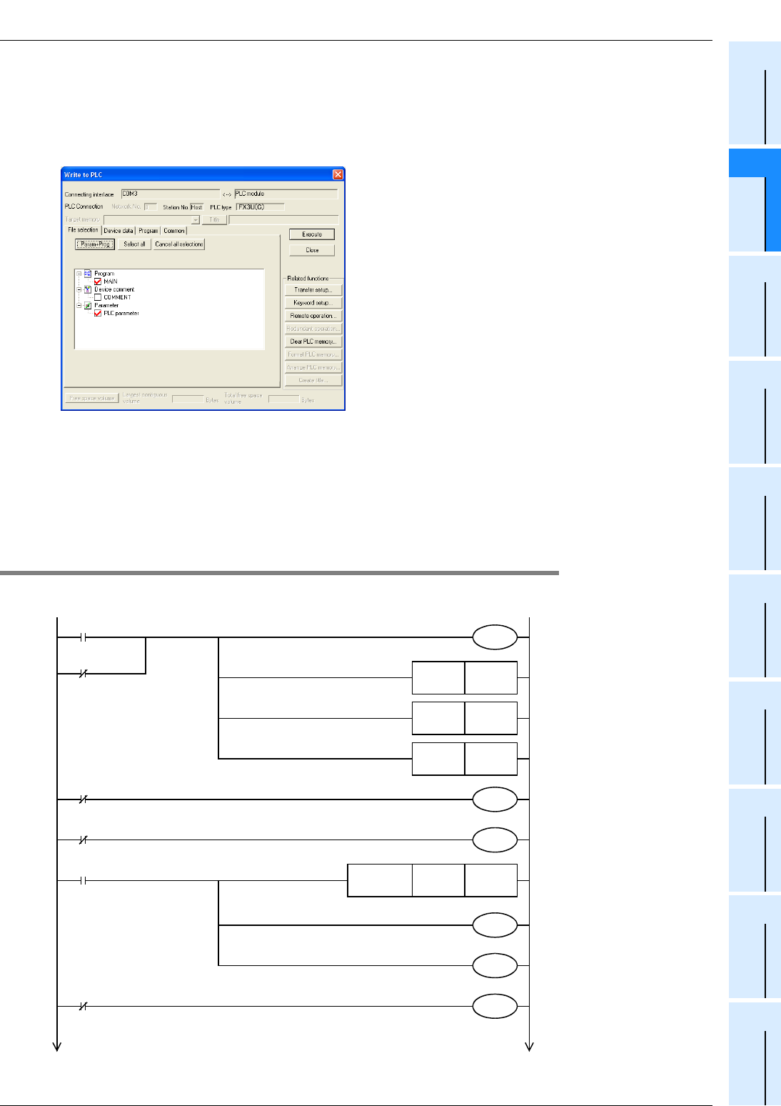
FX
3G
/FX
3U
/FX
3UC
PLC User's Manual - Positioning Control Edition
Built-in Positioning Functions
12 Examples of Programs
12.4 Positioning Using Batch Setting Method
B - 165
A
Common Items
B
Built-in
Positioning
Functions
Apx.
Example
Connection
5Create a program.
6On the bar, click on "Online" and then "Write to PLC". The "Write to PLC"
window will appear.
*2. For Ver. 8.13P to 8.24A of GX Developer, the PLC type is FX3UC.
7Click the "Param+Prog" buttons, and then click the "Execute" button.
The parameters and the created program will be transferred to the PLC.
To enable the transferred parameters, stop the PLC, and then restart it.
12.4.2 Operation Program
An example of a relay ladder program is shown below:
*1
X020 M8349
M8341
X014
Immediate stop
Servo ready
M8000
M8342
M8000
RUN monitor
RUN monitor
M10RST
M12RST
M13RST
M8343
M8344
X026
Forward rotation limit
X027
Reverse rotation limit
D8464H0020
FNC 12
MOVP
M8464
Stops outputting Y000 pulses.
(Immediate stop)
Refer to Subsection 4.7.2.
Enables the origin return
operation with CLEAR signal
outputting function. (CLEAR
signal: Y020)
Performs origin return in the
forward rotation direction.
Resets the "origin return
completion" flag.
Resets the "forward rotation
positioning completion" flag.
Resets the "reversed rotation
positioning completion" flag.
Forward rotation limit(Y000)
Reverse rotation limit(Y000)
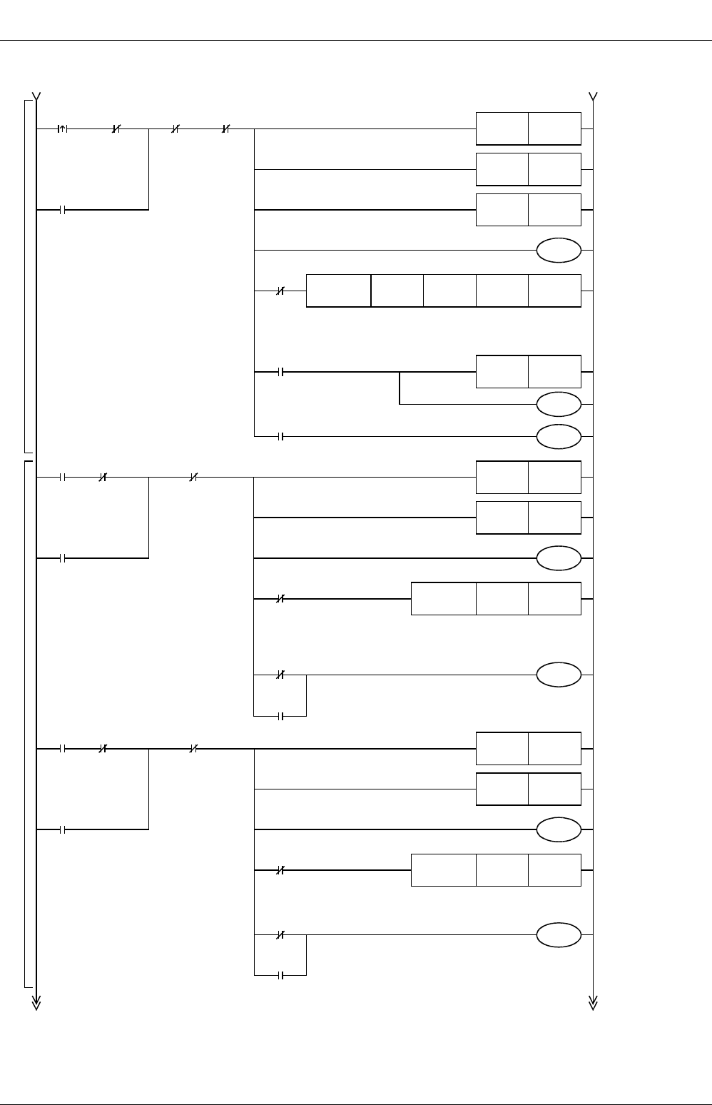
FX
3G
/FX
3U
/FX
3UC
PLC User's Manual - Positioning Control Edition
Built-in Positioning Functions
12 Examples of Programs
12.4 Positioning Using Batch Setting Method
B - 166
Origin
return
M8348
Positioning
being
performed
M10RST
M12RST
M13RST
X021 M101
Normal
end of
origin
return
M100
Origin return
being performed
M102
Abnormal
end of
origin
return
M100
Y004Y000X004X010
FNC 150
DSZR
M8029
"Execution
completion" flag
M10SET
M101
M102
M8329
Abnormal
end
JOG
(+)
M8348 M12RST
X022 M104
Completes
the JOG(+)
operation.
Positioning
being
performed
(Y000)
M13RST
M103
K1Y000
FNC 152
DTBL
Near-point
signal
Zero-point
signal
Pulse
output
destination
number
Rotation
direction
signal
Pulse
output
destination
number
Table
number
M103
JOG(+) operation is
being performed.
X022
JOG(+)
M104
M8329
Abnormal
end
Origin return
Jogging operation
JOG
(-)
M8348 M12RST
X023 M106
Completes
the JOG(-)
operation.
Positioning
being
performed
(Y000)
M13RST
M105
K2Y000
FNC 152
DTBL
Pulse
output
destination
number
Table
number
M105
JOG(-) operation is
being performed.
X023
JOG(-)
M106
M8329
Abnormal
end
X030
Stop
command
X030
Stop
command
X030
Stop
command
Resets the "origin
return completion"
flag.
Resets the "forward
rotation positioning
completion" flag.
Resets the "reverse
rotation positioning
completion" flag.
Origin return is
being performed.
Origin return
instruction with
DOG search
function
(CLEAR signal:
Y020)
Resets the "forward
rotation positioning
completion" flag.
Resets the "reverse
rotation positioning
completion" flag.
JOG(+) operation
is being performed.
Executes No. 1 of
the positioning
table of Y000
(pulse output
destination).
"Origin return
completion" flag
Normal end of
origin return
Abnormal end of
origin return
Completes the
JOG(+) operation.
Resets the "forward
rotation positioning
completion" flag.
Resets the "reverse
rotation positioning
completion" flag.
JOG(-) operation
is being
performed.
Executes No. 2 of
the positioning
table of Y000
(pulse output
destination).
Completes the
JOG(-) operation.
FX
3G
/FX
3U
/FX
3UC
PLC User's Manual - Positioning Control Edition
Built-in Positioning Functions
12 Examples of Programs
12.4 Positioning Using Batch Setting Method
B - 167
A
Common Items
B
Built-in
Positioning
Functions
Apx.
Example
Connection
Position-
ing in
forward
rotation
direction
M8348
Position-
ing
operation
being
performed
X024
M107
Positioning operation being
performed in forward rotation
direction
M107
M8029
"Execution
completion"
flag
M108
M109
M8329
Abnormal end
M10
"Zero
return
compl-
etion"
flag
M108
Normal
end of
positioning
in forward
rotation
direction
M109
Abnormal
end of
positioning
in forward
rotation
direction
Positioning in forward rotation direction
M110
M8029
"Execution
completion"
flag
M111
M112
M8329
Abnormal end
Position-
ing in
reverse
rotation
direction
M8348
Position-
ing
operation
being
performed
(Y000)
X025
M110
Positioning operation being
performed in reverse
rotation direction
M10
"Zero
return
compl-
etion"
flag
M111
Normal
end of
positioning
in reverse
rotation
direction
M112
Abnormal
end of
positioning
in reverse
rotation
direction
Positioning in reverse rotation direction
X030
Stop
command
M12RST
M13RST
K3Y000
FNC 152
DTBL
M12SET
M12RST
M13RST
K4Y000
M13SET
END
X030
Stop
command
FNC 152
DTBL
Pulse
output
destination
number
Table
number
Pulse
output
destination
number
Table
number
"Forward rotation
positioning
completion" flag
"Reverse rotation
positioning
completion" flag
Positioning
operation being
performed in
forward rotation
direction
"Forward rotation
positioning
completion" flag
"Forward rotation
positioning normal
end" flag
"Forward rotation
positioning
abnormal end" flag
"Forward rotation
positioning
completion" flag
"Reverse rotation
positioning
completion" flag
Positioning
operation being
performed in
reverse rotation
direction
Executes No. 4 of
the positioning table
of Y000 (pulse
output destination).
"Reverse rotation
positioning
completion" flag
"Reverse rotation
positioning normal
end" flag
"Reverse rotation
positioning
abnormal end" flag
Executes No. 3 of
the positioning table
of Y000 (pulse
output destination).
FX
3G
/FX
3U
/FX
3UC
PLC User's Manual - Positioning Control Edition
Built-in Positioning Functions
12 Examples of Programs
12.5 Program for Reading Current ABS Value Using ABS Instruction
B - 168
12.5 Program for Reading Current ABS Value Using ABS Instruction
1) Program for storing ABS data in current value registers specified by a positioning instruction for Y000
(pulse output destination)
2) Program for storing ABS data in the current value registers of the FX2N-1PG(-E) or FX2N-10PG
Caution:
*1. The ABS data will be read out as a pulse converted value. For this reason, be sure to specify "motor
system" when setting parameters (BFM #3) for the FX2N-1PG(-E).
*2. When writing the ABS data to the FX2N-10PG, be sure to use the current value registers (BFM #40,
BFM #39) to store the converted pulse data.
M8000
RUN
monitor
FNC155
DABS X031 Y021 D8340
S
•
D
1
•
D
2
•
Reads out the ABS data to the current value registers
D8341 and D8340.
Read time limit (5 sec)
ABS data read error
ABS data reading is complete.
ABS data reading completed
T0
Read time error detected
M8029
"Execution
completion" flag
T0
M2
M 1SET
K50
M1
ABS(bit0) Servo-ON
signal
M8000
RUN
monitor
FNC155
DABS X031 Y021 D100
S
•
D
1
•
D
2
•
Reads out the ABS data to D101 and D100.
Read time limit (5 sec)
ABS data read error
ABS data reading is complete.
Writes data (data converted into pulse data) to the
current value registers #40 and #39 of the FX
2N
-10PG.
*2
Writes data in current value registers #27 and #26 of the
FX
2N
-1PG.
*1
ABS data reading completed
T0
Read time error detected
M8029
"Execution
completion" flag
T0
M2
M 1SET
K50
M1
M1
ABS data
reading is
completed.
D100 U
\G39
FNC12
DMOV
Block No.
BFM#39
(
#40
)
M1
ABS data
reading is
completed.
FNC12
DMOV D100 U
\G26
Block No.
BFM#26(#27)
ABS(bit0) Servo-ON
signal
FX
3G
/FX
3U
/FX
3UC
PLC User's Manual - Positioning Control Edition
Built-in Positioning Functions
13 Troubleshooting
13.1 LED Indicator Lamp Check
B - 169
A
Common Items
B
Built-in
Positioning
Functions
Apx.
Example
Connection
13. Troubleshooting
13.1 LED Indicator Lamp Check
If an error occurs, check the ON/OFF status of the LED indicator lamps on the PLC to assess the general
meaning of the error. This section does not describe all the LED indicator lamps of the main unit. For details
on the LED indicator lamps, refer to the following PLC manuals.
→ Refer to the FX3G Hardware Edition.
→ Refer to the FX3U Hardware Edition.
→ Refer to the FX3UC Hardware Edition.
13.1.1 POWER Indicator Lamp (Statuses: ON, flashing, OFF) [FX3G/FX3U/FX3UC]
Lamp
status Status of PLC Troubleshooting
ON
The specified voltage is properly
supplied to the power supply terminal. The power is being supplied properly.
Flashing
The PLC may be at one of the following
statuses:
•
The specified voltage/current is not
supplied to the power supply
terminal.
•
An external line is not properly
connected.
•
The PLC has a problem.
•Check the power supply voltage.
•Excluding the power cable, disconnect all other cables, and
then turn the power ON again. Check the lamp status. If the
lamp flashes again, please contact the nearest Mitsubishi
Electric distributor office .
FX3U PLC
FX3UC-32MT-LT (-2) PLC
FX3UC (D, DSS) PLC
FX3G PLC

FX
3G
/FX
3U
/FX
3UC
PLC User's Manual - Positioning Control Edition
Built-in Positioning Functions
13 Troubleshooting
13.1 LED Indicator Lamp Check
B - 170
OFF
The PLC may be at one of the following
statuses:
•The power is off.
•The specified voltage is not
supplied to the power supply
terminal.
•The power cable is disconnected.
If the power is on, check the power supply unit and the power supply
line.
If the power is properly supplied, please contact the nearest
Mitsubishi Electric
distributor
office.
Lamp
status Status of PLC Troubleshooting

FX
3G
/FX
3U
/FX
3UC
PLC User's Manual - Positioning Control Edition
Built-in Positioning Functions
13 Troubleshooting
13.1 LED Indicator Lamp Check
B - 171
A
Common Items
B
Built-in
Positioning
Functions
Apx.
Example
Connection
13.1.2 RUN Indicator Lamp (Statuses: ON, OFF) [FX3G/FX3U/FX3UC]
13.1.3 BATT Indicator Lamp (Statuses: ON, OFF) [FX3U/FX3UC]
13.1.4 ALM Indicator Lamp (Statuses: ON, OFF) [FX3G]
This LED is valid when the optional battery is installed and the battery mode is selected using a parameter.
13.1.5 ERROR indicator lamp (Statuses: ON, flashing, OFF) [FX3G/FX3U/FX3UC]
Lamp
status Status of PLC Troubleshooting
ON
The sequence program is being
executed. The RUN indicator lamp indicates the operation status of the PLC.
Note that the RUN indicator lamp will go out depending on the status
of the ERROR indicator lamp (refer to Subsection 13.1.4).
OFF
Execution of the sequence program is
stopped.
Lamp
status Status of PLC Troubleshooting
ON
The voltage of the battery is too low. Immediately replace the battery (refer to the manual of the PLC).
OFF
The battery supplies enough voltage as
specified by D8006. The PLC has no problems.
Lamp
status Status of PLC Troubleshooting
ON
The voltage of the battery is too low. Immediately replace the battery (refer to the manual of the PLC).
OFF
The battery supplies enough voltage as
specified by D8006. The PLC has no problems.
Lamp
status Status of PLC Troubleshooting
ON
A watchdog timer error may have
been detected, or the hardware of the
PLC may be damaged.
1) Stop the PLC, and then turn the power ON again. If the
ERROR (ERR) indicator lamp goes out, check to see if a
watchdog timer error has been detected, and take one of the
following measures.
- Review the program.
The maximum value of the scanning time (D8012) should
not be larger than the set value of the watchdog timer
(D8000).
- The interrupt input and the pulse catch input should not be
turned on and off too frequently during 1 scan time.
- The frequency of the pulse input to the high-speed counter
should not exceed the specified range (duty:50%)
- Add several WDT instructions.
Set several WDT instructions in the program so that the
watchdog timer can be reset several times during 1 scan
time.
- Change the set value of the watchdog timer.
Using the program, change the set value of the watchdog
timer (D8000) so that the set value of the watchdog timer
(D8000) can be larger than the maximum value of the
scanning time (D8012).
2) Remove the PLC, and put it on a workbench. Supply another
source of power to the PLC.
If the ERROR (ERR) indicator lamp does not light, the cause
of the problem may be noise. In this case, take the following
measures.
- Check the grounding line, and change the wiring route and
the installation place.
- Adopt a noise filter for the power supply line.
3) If measures 1) and 2) do not turn the ERROR indicator lamp
OFF, please contact the nearest
Mitsubishi Electric
distributor
office.

FX
3G
/FX
3U
/FX
3UC
PLC User's Manual - Positioning Control Edition
Built-in Positioning Functions
13 Troubleshooting
13.1 LED Indicator Lamp Check
B - 172
Flashing
The PLC has one of the following
errors:
•Parameter error
•Syntax error
•Circuit error
Diagnose the PLC (PC), or check the programs using the
programming tool.
For countermeasures, refer to the following manual of the applied
PLC.
→ Programming manual
OFF Errors that can stop the PLC are not
detected.
If an operation error is detected on the PLC, diagnose the PLC
(PC), or check the programs using the programming tool. There
is a good possibility that an "I/O configuration error", "parallel link/
communication error", or "operation error" has been detected.
Lamp
status Status of PLC Troubleshooting

FX
3G
/FX
3U
/FX
3UC
PLC User's Manual - Positioning Control Edition
Built-in Positioning Functions
13 Troubleshooting
13.1 LED Indicator Lamp Check
B - 173
A
Common Items
B
Built-in
Positioning
Functions
Apx.
Example
Connection
13.1.6 Pulse Output Destination Device and Rotation Direction Output Indicator Lamp
1. If transistor outputs from the main unit are used for positioning
Signal
LED status during
execution of
positioning
instruction
Description
"Pulse output
destination
device" (pulse
train) signal
Turned on and off at
high speed The pulse outputting operation is controlled by the positioning instruction.
OFF
The PLC may exhibit the following status:
1) The operation of the positioning instruction is completed.
2) The positioning instruction turns ON, but an operation error is detected.
The instruction, therefore, is not being executed. To check the error,
refer to the following section:
→ Refer to Subsection 13.2.1 "Error code check method".
"Rotation
direction output"
(direction) signal
ON Operation is being performed in the forward rotation direction.
OFF
The PLC may exhibit the following status:
1) The positioning instruction turns ON, and operation is being performed
in the reverse rotation direction.
2) The positioning instruction turns ON, but an operation error is detected.
The instruction, therefore, is not being executed. To check the error,
refer to the following section:
→ Refer to Subsection 13.2.1 "Error Code Check Method".

FX
3G
/FX
3U
/FX
3UC
PLC User's Manual - Positioning Control Edition
Built-in Positioning Functions
13 Troubleshooting
13.1 LED Indicator Lamp Check
B - 174
2. If the high-speed output special adapter (FX3U-2HSY-ADP) is used for positioning
Status of pulse
output method
setting switch
Signal
LED status during
execution of
positioning
instruction
Description
PLS•DIR side
"Pulse output
destination device"
(pulse train)
Turned on and off
at high speed
The pulse outputting operation is controlled by the
positioning instruction.
OFF
The PLC may exhibit the following status:
1) The operation of the positioning instruction is
completed.
2) An operation error occurred during positioning.
The instruction, therefore, is not being executed.
To check the error, refer to the following section:
→ Refer to Subsection 13.2.1 "Error Code
Check Method".
"Rotation direction
output" (direction)
ON Forward operation is in execution.
OFF
The PLC may exhibit the following status:
1) The positioning instruction turns ON, and operation
is being performed in the reverse rotation direction.
2) An operation error occurred during positioning
instruction. The instruction, therefore, is not being
executed.
To check the error, refer to the following section:
→ Refer to Subsection 13.2.1 "Error Code
Check Method".
FP/RP side
"Pulse output
destination device"
(Forward pulse train)
Turned on and off
at high speed
Forward operation is being executed for a positioning
instruction. Reverse pulse train is OFF.
OFF
The PLC may exhibit the following status:
1) The positioning instruction turns ON, and operation
is being performed in the reverse rotation direction.
2) An operation error occurred during positioning .
The instruction, therefore, is not being executed.
To check the error, refer to the following section:
→ Refer to Subsection 13.2.1 "Error Code
Check Method".
"Rotation direction
output" (Reverse
pulse train)
Turned on and off
at high speed
Reverse operation is being executed for a positioning
instruction. Forward pulse train is OFF.
OFF
The PLC may exhibit the following status:
1) The positioning instruction turns ON, and operation
is being performed in the forward rotation direction.
2) An operation error occurred during positioning. The
instruction, the4refore, is not being executed.
To check the error, refer to the following section:
→ Refer to Subsection 13.2.1 "Error Code
Check Method".
FX
3G
/FX
3U
/FX
3UC
PLC User's Manual - Positioning Control Edition
Built-in Positioning Functions
13 Troubleshooting
13.2 Error Check
B - 175
A
Common Items
B
Built-in
Positioning
Functions
Apx.
Example
Connection
13.2 Error Check
13.2.1 Error Code Check Method
This section describes how to check the error codes using GX Developer.
If the display module is being used, use the "error check" function of the display module to check the error codes.
For details on the operation of the display module, refer to the following manuals:
→ FX3G Hardware Edition.
→ FX3U Hardware Edition.
→ FX3UC Hardware Edition.
1Connect a personal computer to the PLC.
2Diagnose the PLC.
On the tool menu bar, click on "Diagnostics", and then "PLC diagnostics" to diagnose the cause of the PLC
error.
3Check the diagnosis result.
The following window will appear. Check the details of the error shown on the window.
The help function of
GX Developer opens,
and you can check
the details of the
error code.
Display of
conditions of
LEDs on FX
PLC
The PLC error
is displayed.
<Example of screen displayed
in normal state>
<Example of error display screen>

FX
3G
/FX
3U
/FX
3UC
PLC User's Manual - Positioning Control Edition
Built-in Positioning Functions
13 Troubleshooting
13.2 Error Check
B - 176
13.2.2 Error Codes
This section describes the error codes related to the positioning instructions. For details on the error codes,
refer to the following manual.
→ Refer to the programming manual.
Error
code
Operation
after
detecting
error
Description of error Troubleshooting
Operation error [M8067 (D8067)]
0000
Operation
will be
continued.
No error detected
6705
The device specified by the operand of the
applied instruction is a wrong device.
This error occurs during operation. Check the program or
the operand of the applied instruction.
Even if no syntax error or circuit error is detected, an
operation error may occur for the following reason:
Example:
T500Z is not an error. However, if Z = 100, the result of
operation will be T600. This means that the device
number is out of the specified range, and an operation
error will be detected.
6706
The device number or the data specified by
the operand of the applied instruction is out of
the specified range.
6760 Sum error of ABS data sent from servo
amplifier
Check the servo amplifier for disconnection. Also check
the set data.
6763
1) The input (X) specified by the DSZR,
DVIT, or ZRN instruction is already being
used for another instruction.
2) The interruption signal device number
specified by the DVIT instruction is
outside the setting range.
1) Check that the input (X) specified by the DSZR, DVIT,
or ZRN instruction is not being used for the following
items:
- Input interruption (including delay function)
- High-speed counter (C235 to C255)
- Pulse catch (M8170 to M8177)
- SPD instruction
2) Check the data set in D8336
(interruption signal designation device for DVIT
instruction).
6764
The pulse output number is already being
used for a positioning instruction or pulse
output instruction (PLSY, PWM,etc.).
Check that the output specified as the pulse output
destination is not being activated by another positioning
instruction.

FX
3G
/FX
3U
/FX
3UC
PLC User's Manual - Positioning Control Edition
Built-in Positioning Functions
13 Troubleshooting
13.3 If the Servo Motor or the Stepping Motor Does Not Operate
B - 177
A
Common Items
B
Built-in
Positioning
Functions
Apx.
Example
Connection
13.3 If the Servo Motor or the Stepping Motor Does Not Operate
If the servo motor or the stepping motor does not operate, check the following items.
1) Check the wiring condition.
→ For output specifications, refer to Section 2.5.
→ To connect the MELSERVO Series, refer to the examples of connection shown in the Appendix.
→ For details on the servo amplifier (drive unit), refer to the manual of your unit.
2) Execute the positioning instruction, and then check the statuses of the following LED indicator lamps.
→ For details on lamp statuses, refer to Subsection 13.1.5.
- LED indicator lamp of the output specified as the pulse output destination
- LED indicator lamp of the output specified as the rotation direction output device
3) Verify that the same pulse output method is being applied for both the PLC and the servo amplifier (drive
unit).
→ For details on the pulse output method, refer to Subsection 4.6.1.
→ For details on high-speed output special adapter setting method,refer to Subsection 4.5.2.
4) Check that the pulse output stop command flag is off.
→ For details on the pulse output stop command flag, refer to Subsection 4.3.2.
The following table shows the pulse output stop command flag of each pulse output destination device
(Y000, Y001, Y002, Y003).
5) Check that the limit switch (forward or reverse rotation limit switch) is not activated.
→ For details on the normal and reverse rotation limits, refer to Subsection 4.3.1.
The following table shows the forward and reverse limit relays of each pulse output destination device
(Y000, Y001, Y002, Y003).
6) Check the operation timing of the positioning instruction.
If the "pulse output monitor" (BUSY/READY) flag is on, and if a positioning instruction (excluding the ABS
instruction) or pulse output instruction (PLSR, PLSY) uses the same pulse output destination device, the
instruction cannot be executed.
If the "pulse output monitor" (BUSY/READY) flag is still on after the instruction activation contact is turned
off, do not execute a positioning instruction (including PLSR and PLSY instructions) that uses the same
output number.
Before activating such an instruction, check that the "pulse output monitor" (BUSY/READY) flag is off,
and then wait until at least 1 scan time is completed.
Pulse output destination
device
Pulse output stop
command flag Operation
Y000 M8349 During pulse outputting operation, if the pulse output stop
command flag of a corresponding pulse output destination
device is turned on, the pulse outputting operation will be
immediately stopped.
Y001 M8359
Y002 M8369
Y003 M8379
Pulse output
destination
device
Forward limit
relay
Reverse limit
relay
Corresponding instruction and stop
PLSV instruction
(M8338 = OFF)
DSZR, DVIT, ZRN,
PLSV(M8338 = ON), DRVI,
and DRVA instructions
Y000 M8343 M8344 If the corresponding rotation
limit relay is turned on, the
pulse output (operation) will
immediately stop.
If the corresponding rotation
limit relay is turned on, the
speed will decelerate, and the
operation will stop.
Y001 M8353 M8354
Y002 M8363 M8364
Y003 M8373 M8374
Pulse output destination device Pulse output monitor flag
Y000 M8340
Y001 M8350
Y002 M8360
Y003 M8370

FX
3G
/FX
3U
/FX
3UC
PLC User's Manual - Positioning Control Edition
Built-in Positioning Functions
13 Troubleshooting
13.4 If Operation Is Stopped at a Wrong Position
B - 178
13.4 If Operation Is Stopped at a Wrong Position
If operation is stopped at a wrong position, check the following items.
1) Check whether the electronic gear of the servo amplifier (drive unit) is set properly.
→ For the electronic gear setting method of the MELSERVO Series, refer to Subsection 4.6.2.
2) Check whether the origin is set properly.
•Properly set the DOG so that the near-point signal (DOG) can be kept ON until the speed is reduced to
the creep speed. The zero return instruction will start speed reduction at the front end of the DOG, and
will stop the operation at the rear end of the DOG or at detection of the first zero-phase signal after
passing the rear end of the DOG. After that, the current value register will be cleared (reset to "0"). If
the speed is not reduced to the creep speed before detecting the rear end of the DOG, the operation
may not be stopped at the specified position.
•The creep speed should be slow enough. The zero return instruction will not reduce the speed before
stopping. For this reason, if the creep speed is not slow enough, the operation may not be stopped at
the specified position due to inertia.
•Devices for the near-point signal (DOG)
- DSZR instruction
If an input (X000 to X017)*1 of the main unit is specified for the near-point signal (DOG), the rear end
of the near-point signal (DOG) will be monitored (detected) at 1-ms intervals (interruption). Under the
following condition, however, monitoring (detection) of the near-point signal (DOG) rear end may be
affected by the input time constant or the scan time of the sequence program, and the operation may
not be stopped at the specified position.
a) An input number of X020 or below (or other device (auxiliary relay, etc.)) is specified.
*1.When using an FX
3U
-16M
, FX
3UC
-16M
, specify an input in the range of X000 to X007.
X000 to X007 for FX
3G
PLC (main unit).
- ZRN instruction
If an input (X000 to X007) of the main unit is specified for the near-point input signal, the PLC
interruption function will be used to stop the operation. Under the following condition, however,
operation may be affected by the scan time of the sequence program, and the operation may not be
stopped at the specified position.
a) An input number of X010 or below (or other device (auxiliary relay, etc.)) is specified. If an input
relay X010 or below is specified for the near-point signal, the input filter (10 ms) will apply.
•If the DSZR instruction is used:
Since the zero-phase signal of the servo motor is used, adjust the relation between the rear end of the
DOG and the zero-phase signal as shown in the following figure. If fine adjustment of the origin
position is needed, adjust the position of the near-point signal (DOG).
3) If reciprocating operation (operation in the forward rotation direction and then reverse rotation direction) is
not stopped at the specified position: The built-in positioning function cannot correct the mechanical
backlash (clearance, play) during positioning operation. If it is necessary to correct the backlash,
preliminarily set the number of output pulses considering the backlash that may be caused when
changing the transfer direction.
DOG
Rear end
Zero-phase signal
Table
Feed screw
Backlash
(clearance, play)

Apx. - 1
FX
3G
/FX
3U
/FX
3UC
PLC User's Manual - Positioning Control Edition
Example Connection
A
Common Items
B
Built-in
Positioning
Functions
Apx.
Example
Connection
FX3G/FX3U/FX3UC Series Programmable
Controllers
User's Manual [Positioning Control Edition]
Appendix: Example Connection
Foreword
To use the positioning function of the MELSEC-F FX3G/FX3U/FX3UC Series PLC described in this manual, the
PLC should be connected to a servo amplifier drive unit. The Appendix, therefore, describes how to connect
the PLC to a servo amplifier drive unit and should be read and understood before attempting to install or use
the unit.
Store this manual in a safe place so that you can take it out and read it whenever necessary. Always forward
it to the end user.
© 2005 MITSUBISHI ELECTRIC CORPORATION
This manual confers no industrial property rights or any rights of any other kind, nor does it confer any patent
licenses. Mitsubishi Electric Corporation cannot be held responsible for any problems involving industrial property
rights which may occur as a result of using the contents noted in this manual.
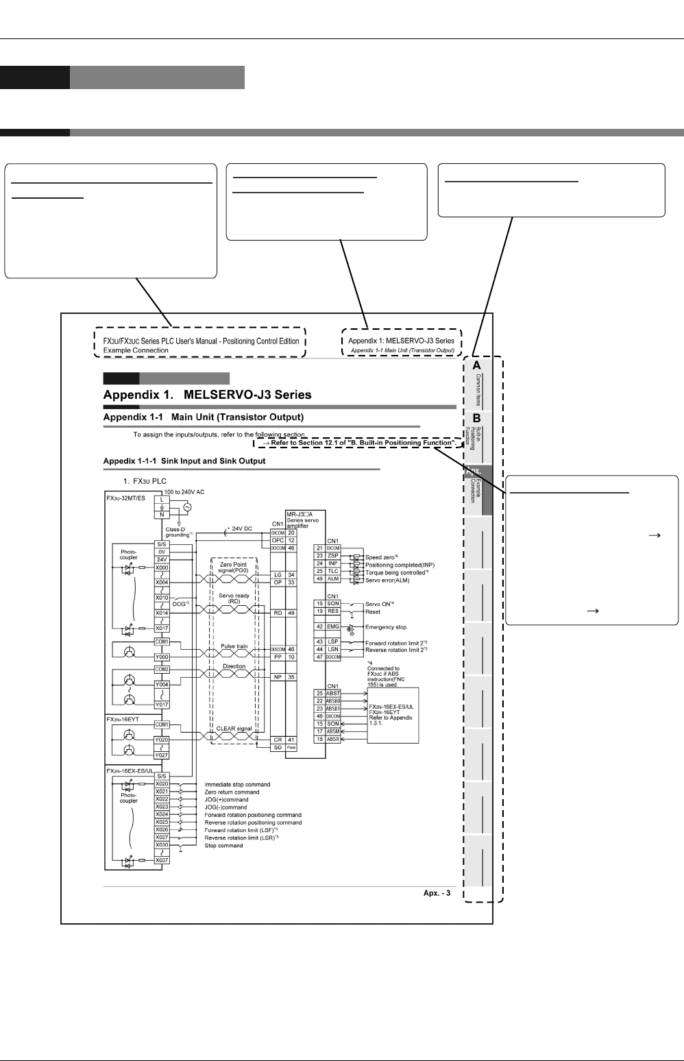
Apx. - 2
FX
3G
/FX
3U
/FX
3UC
PLC User's Manual - Positioning Control Edition
Example Connection
Description of Manual (Example of Connection)
In this manual, the following formats are used for describing the examples of connection:
The above is different from the actual page, as it is provided for explanation only.
Shows the title of the manual and the title
of the division.
This area shows the title of the manual
and the title of the division for the current
page.
1st line: Shows the title of the manual.
2nd line: Shows the title of the division.
Shows the title of the chapter
and the title of the section.
This area shows the title of the chapter
and the title of the section for the
current page.
Indexes the division titles.
The right side of each page indexes the title
of the division for the current page.
Shows the reference.
This area shows the reference
document (the reference
document is shown next to " ").
If the reference is in
"Appendix: Examples of
Connection", the chapter, section,
or item number only will be
shown next to " " .
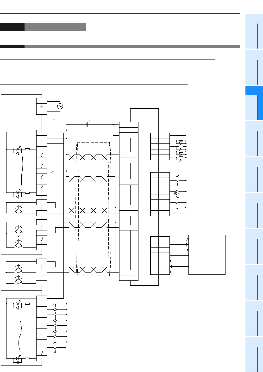
FX
3G
/FX
3U
/FX
3UC
PLC User's Manual - Positioning Control Edition
Example Connection
Appendix 1: MELSERVO-J3 Series
Appendix 1-1 Main Unit (Transistor Output)
Apx. - 3
A
Common Items
B
Built-in
Positioning
Functions
Apx.
Example
Connection
Appendix 1. MELSERVO-J3 Series
Appendix 1-1 Main Unit (Transistor Output)
To assign the inputs/outputs, refer to the following section.
→ Refer to Section 12.1 of "B. Built-in Positioning Function".
Appedix 1-1-1 Sink Input and Sink Output
1. FX3U/FX3G PLC
LG
OP
DOCOM
PP
CN1
34
33
46
10
DOCOM
DICOM
46
20
OPC 12
NP 35
RD 49
DICOM
ZSP
INP
21
23
24
TLC25
ALM48
CN1
SON
RES
EMG
15
19
42
LSP43
LSN44
CN1
DOCOM
47
ABST
ABSB0
ABSB1
25
22
23
DOCOM
46
SON15
ABSM
ABSR
17
18
CN1
FX
2N
-16EX-ES/UL
FX
2N
-16EYT
Refer to Appendix
1.3.1-1.
24V DC
CR 41
SD
Plate
DOG
*2
L
24V
X004
X017
FX
3U
-32MT/ES
X010
X014
X000
COM1
COM2
Y000
Y007
Y004
S/S
X020
FX
2N
-16EX-ES/UL
X021
X022
X023
X024
X026
X027
X037
X025
X030
COM1
FX
2N
-16EYT
Y020
Y027
Photo-
coupler
Photo-
coupler
N
Immediate stop command
Zero return command
JOG(+)command
JOG(-)command
Forward rotation positioning command
Forward rotation limit (LSF)
*3
Reverse rotation limit (LSR)
*3
Reverse rotation positioning command
Stop command
Class-D
grounding
*1
Zero Point
signal(PG0)
Servo ready
(RD)
Pulse train
CLEAR signal
MR-J3
A
Series servo
amplifier
Zero speed
*4
Positioning completed(INP)
Torque being controlled
*4
Servo error(ALM)
*4
Connected to the
FX
3U
if the ABS
instruction (FNC 155)
is used.
Servo ON
*4
Reset
Emergency stop
Forward rotation limit 2
*3
Reverse rotation limit 2
*3
Direction
100 to 240V AC
0V
S/S

FX
3G
/FX
3U
/FX
3UC
PLC User's Manual - Positioning Control Edition
Example Connection
Appendix 1. MELSERVO-J3 Series
Appendix 1-2 High-Speed Output Special Adapter
Apx. - 4
*1. Be sure to use the class-D grounding method (grounding resistance: 100
Ω
or less).
*2. Near-point signal (DOG)
*3. To ensure safety, use the forward rotation limit switch and the reverse rotation limit switch on both sides: the PLC side and
the servo amplifier side.
Note that the limit switches on the PLC side should be activated slightly earlier than the limit switches on the servo
amplifier side.
*4. To detect absolute positions, connect this line to the PLC.
Reverse rotation limit 2
(Servo amplifier side)
Reverse rotation limit 1
(Programmable
controller side)
LSR
Forward rotation limit 2
(Servo amplifier side)
Forward rotation limit 1
(Programmable
controller side)
LSF
Reverse rotation Forward rotation
Servo motor
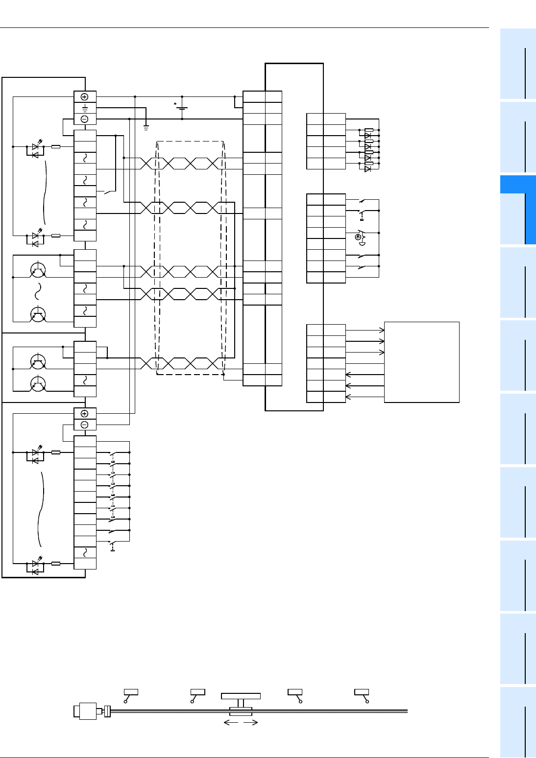
FX
3G
/FX
3U
/FX
3UC
PLC User's Manual - Positioning Control Edition
Example Connection
Appendix 1: MELSERVO-J3 Series
Appendix 1-1 Main Unit (Transistor Output)
Apx. - 5
A
Common Items
B
Built-in
Positioning
Functions
Apx.
Example
Connection
2. FX3UC PLC
*1. Be sure to use the class-D grounding method (grounding resistance: 100
Ω
or less).
*2. Near-point signal (DOG)
*3. To ensure safety, use the forward rotation limit switch and the reverse rotation limit switch on both sides: the PLC side and
the servo amplifier side.
Note that the limit switches on the PLC side should be activated slightly earlier than the limit switches on the servo
amplifier side.
*4. To detect absolute positions, connect this line to the PLC.
LG
OP
DOCOM
PP
CN1
34
33
46
10
DOCOM
DICOM
46
20
OPC 12
NP 35
RD 49
DICOM
ZSP
INP
21
23
24
TLC25
ALM48
CN1
SON
RES
EMG
15
19
42
LSP43
LSN44
CN1
DOCOM
47
ABST
ABSB0
ABSB1
25
22
23
DOCOM
46
SON15
ABSM
ABSR
17
18
CN1
FX
2NC
-16EX
FX
2NC
-16EYT
Refer to Appendix
1.3.1-2.
24V DC
CR 41
SD
Plate
DOG
*2
COM
X004
X017
FX
3UC
-32MT/D
X010
X014
X000
COM1
COM1
Y000
Y017
Y004
COM
X020
FX
2NC
-16EX
X021
X022
X023
X024
X026
X027
X037
X025
X030
COM1
FX
2NC
-16EYT
Y020
Y027
COM1
Photo-
coupler
Photo-
coupler
Immediate stop command
Zero return command
JOG(+)command
JOG(-)command
Forward rotation positioning command
Forward rotation limit (LSF)
*3
Reverse rotation limit (LSR)
*3
Reverse rotation positioning command
Stop command
Class-D
grounding
*1
Zero Point
signal(PG0)
Servo ready
(RD)
Pulse train
CLEAR signal
MR-J3
A
Series servo
amplifier
Zero speed
*4
Positioning completed(INP)
Torque being controlled
*4
Servo error(ALM)
*4
Connected to the
FX
3UC
if the ABS
instruction(FNC
155) is used.
Servo ON
*4
Reset
Emergency stop
Forward rotation limit 2
*3
Reverse rotation limit 2
*3
Direction
Reverse rotation limit 2
(Servo amplifier side)
Reverse rotation limit 1
(Programmable
controller side)
LSR
Forward rotation limit 2
(Servo amplifier side)
Forward rotation limit 1
(Programmable
controller side)
LSF
Reverse rotation Forward rotation
Servo motor
FX
3G
/FX
3U
/FX
3UC
PLC User's Manual - Positioning Control Edition
Example Connection
Appendix 1. MELSERVO-J3 Series
Appendix 1-2 High-Speed Output Special Adapter
Apx. - 6
Appendix 1-2 High-Speed Output Special Adapter
To assign the inputs/outputs, refer to the following section.
→ Refer to Section 12.1 of "B. Built-in Positioning Function".
Appedix 1-2-1 Sink Input, Sink Output (Transistor), and Differential Line Driver Output
*1. Be sure to use the class-D grounding method (grounding resistance: 100
Ω
or less).
*2. Near-point signal (DOG)
Y0/2+
FX
3U
-2HSY-ADP
Y0/2-
SGA
Y4/6+
Y4/6-
Epuivalent to
AM26C31
SGA
Pulse train
(Forward rotation
pulse train)*
5
LG
OP
DOCOM
SD
34
33
46
41
Plate
DOCOM
DICOM
46
20
CN1
OPC 12
DICOM
ZSP
INP
21
23
24
TLC25
ALM48
CN1
SON
RES
EMG
15
19
42
LSP43
LSN44
CN1
DOCOM
47
ABST
ABSB0
ABSB1
25
22
23
46
SON15
ABSM
ABSR
17
18
CN1
FX
2N
-16EX-ES/UL
FX
2N
-16EYT
Refer to Appendix
1.3.1-1.
NP 35
RD 49
CR
PP 10
PG 11
NG 36
DOCOM
S/S
X020
FX
2N
-16EX-ES/UL
X021
X022
X023
X024
X026
X027
X037
X025
X030
COM1
FX
2N
-16EYT
Y020
Y027
DOG
*2
X004
X017
FX
3U
-32MR/ES
X010
X014
X000
24V
0V
S/S
N
L
100V to
240V AC
24V DC
Photo-
coupler
Photo-
coupler
Class-D
grounding
*1
Zero Point
signal(PG0)
Servo ready
(RD)
CLEAR signal
MR-J3
A
Series servo
amplifier
Zero speed
*4
Positioning completed(INP)
Torque being controlled
*4
Servo error(ALM)
*4
Connected to the
FX
3UC
if the ABS
instruction(FNC
155) is used.
Servo ON
*4
Reset
Emergency stop
Forward rotation limit 2
*3
Reverse rotation limit 2
*3
Immediate stop command
Zero return command
JOG(+)command
JOG(-)command
Forward rotation positioning command
Forward rotation limit (LSF)
*3
Reverse rotation limit (LSR)
*3
Reverse rotation positioning command
Stop command
Direction signal
(Reverse rotation
pulse train)*
5
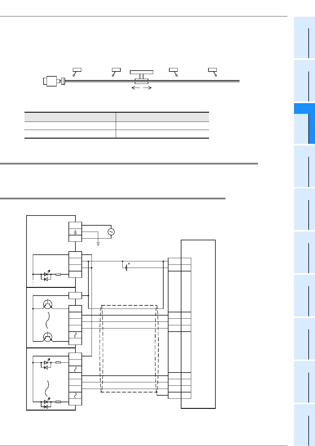
FX
3G
/FX
3U
/FX
3UC
PLC User's Manual - Positioning Control Edition
Example Connection
Appendix 1: MELSERVO-J3 Series
Appendix 1-3 Absolute Position Detection (Transistor Output)
Apx. - 7
A
Common Items
B
Built-in
Positioning
Functions
Apx.
Example
Connection
*3. To ensure safety, use the forward rotation limit switch and the reverse rotation limit switch on both sides: the PLC side and
the servo amplifier side. Note that the limit switches on the PLC side should be activated slightly earlier than the limit
switches on the servo amplifier side.
*4. To detect absolute positions, connect this line to the PLC.
*5. Set the pulse output form by pulse output form setting switch.
Appendix 1-3 Absolute Position Detection (Transistor Output)
To assign the inputs/outputs, refer to the following section.
→ Refer to Section 12.1 of "B. Built-in Positioning Function"
Appendix 1-3-1 Sink Input and Sink Output
1. FX3U/FX3G PLC
*1. Be sure to use the class-D grounding method (grounding resistance: 100
Ω
or less).
Pulse output method setting switch Pulse output method
FP•RP side Forward/reverse pulse train
PLS•DIRside Pulse train + direction
Reverse rotation limit 2
(Servo amplifier side)
Reverse rotation limit 1
(Programmable
controller side)
LSR
Forward rotation limit 2
(Servo amplifier side)
Forward rotation limit 1
(Programmable
controller side)
LSF
Reverse rotation Forward rotation
Servo motor
FX
3U
-32MT/ES
X000
24V
0V
S/S
N
L
100V to 240V AC
COM1
FX
2N
-16EYT
Y020
Y27
Y021
Y022
Y023
ABS(bit0)
ABS(bit1)
DOCOM
46
22
DICOM
20
ABST 25
ABSB
123
SD
Plate
CN1
SON 15
ABSR
18
ABSM
17
ABSB0
22
ABST 25
ABSB1
23
S/S
X020
FX
2N
-16EX-ES/UL
X031
X032
X033
X037
24V DC
Photo-
coupler
Photo-
coupler
Class-D
grounding
*1
Servo-ON
ABS transfer mode
ABS request
MR-J3
A
Series servo
amplifier
Send data ready
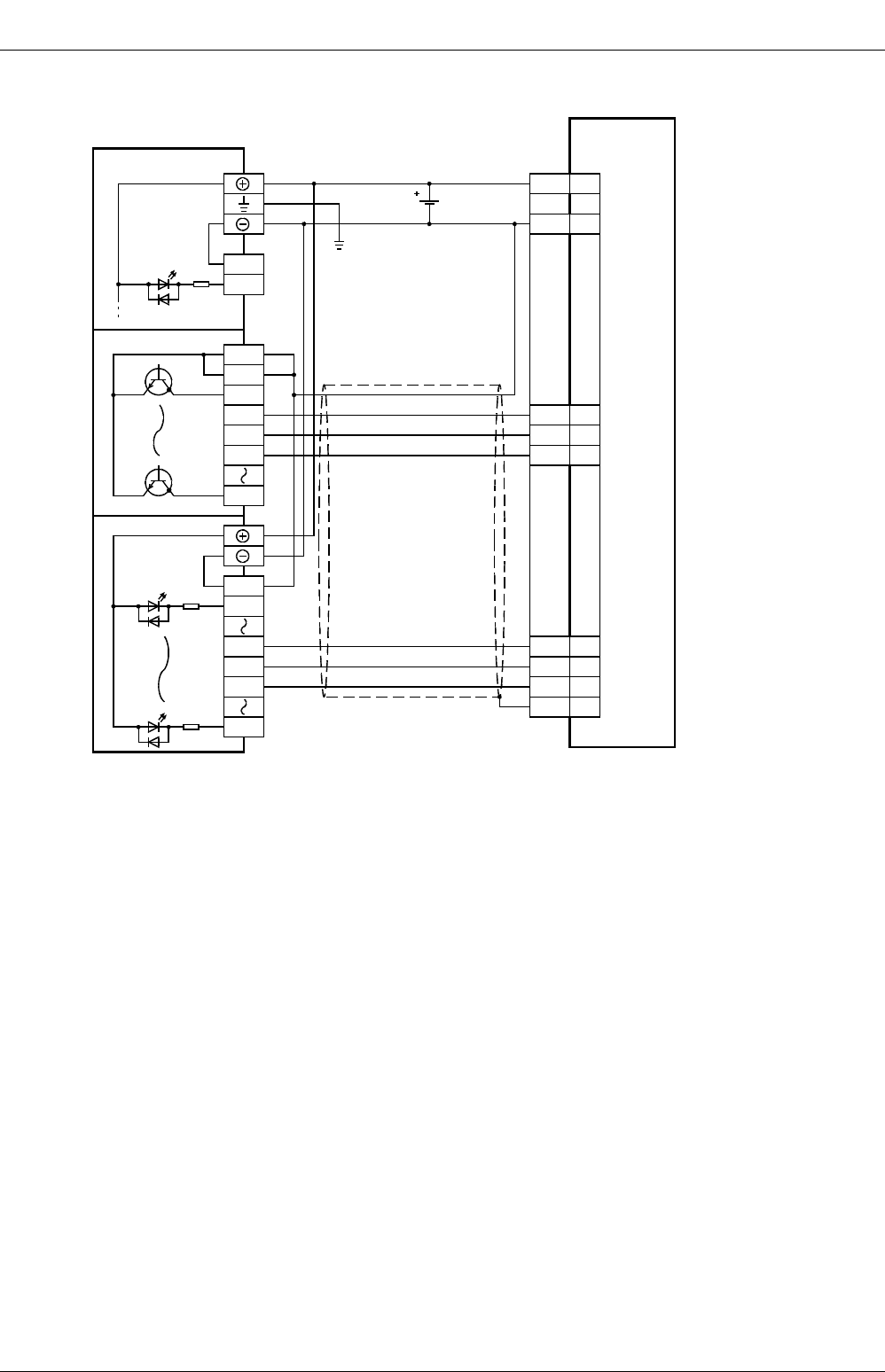
FX
3G
/FX
3U
/FX
3UC
PLC User's Manual - Positioning Control Edition
Example Connection
Appendix 1. MELSERVO-J3 Series
Appendix 1-2 High-Speed Output Special Adapter
Apx. - 8
2. FX3UC PLC
*1. Be sure to use the class-D grounding method (grounding resistance: 100
Ω
or less).
FX
3UC
-32MT/D
DOCOM
46
22
DICOM
20
ABST 25
23
SD
Plate
CN1
24V DC
COM1
FX
2NC
-16EYT
Y020
Y027
COM1
Y021
Y022
Y023
COM
X000
COM
X020
FX
2NC
-16EX
X031
X032
X033
X037
SON 15
ABSR
18
ABSM
17
ABSB0
22
ABST
25
ABSB1
23
Photo-
coupler
Photo-
coupler
Class-D
grounding
*1
ABS(bit0)
ABS(bit1)
Servo-ON
ABS transfer mode
ABS request
Send data ready
MR-J3
A
Series servo
amplifier
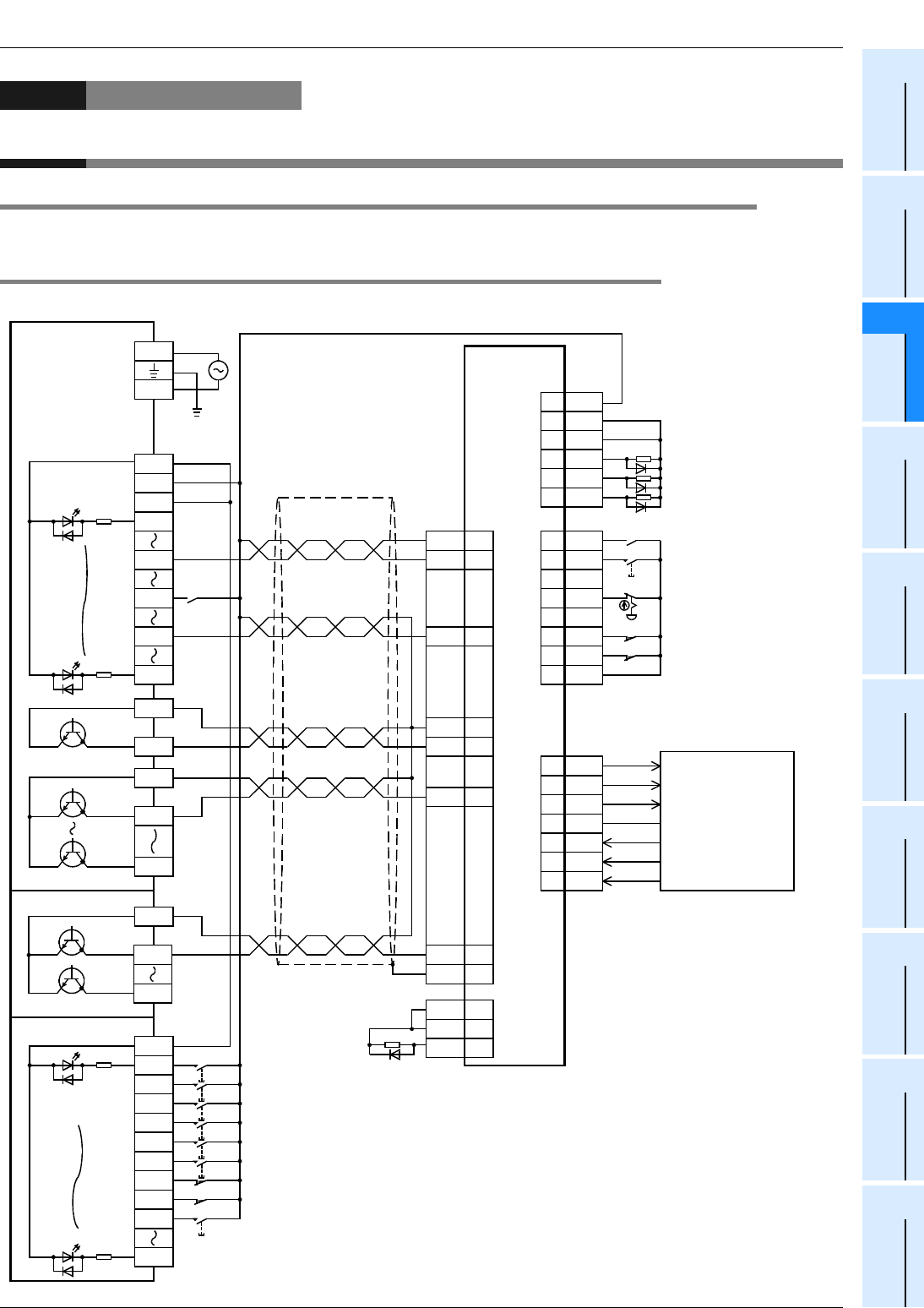
FX
3G
/FX
3U
/FX
3UC
PLC User's Manual - Positioning Control Edition
Example Connection
Appendix 2. MELSERVO-J2 (-Super) Series
Appendix 2-1 Main Unit (Transistor Output)
Apx. - 9
A
Common Items
B
Built-in
Positioning
Functions
Apx.
Example
Connection
Appendix 2. MELSERVO-J2 (-Super) Series
Appendix 2-1 Main Unit (Transistor Output)
To assign the inputs/outputs, refer to the following section.
→ Refer to Section 12.1 of "B. Built-in Positioning Function".
Appendix 2-1-1 Sink Input and Sink Output
1. FX3U/FX3G PLC
9
COM
SON
RES
EMG
5
14
15
LSP16
LSN17
CN1B
SG20
DO1
ZSP
TLC
4
19
6
SG10
SON5
ABSM
ABSR
8
9
CN1B
SG
COM
10
13
CN1B
ZSP19
TLC6
ALM18
FX
2N
-16EX-ES/UL
FX
2N
-16EYT
Refer to Appendix
2.3.1-1.
Positioning
completed(INP)
Zero speed
*5
Torque being controlled
*5
Servo error(ALM)
MR-J2(S)
A
Series servo
amplifier
*5
Connected to the
FX
3U
if the ABS
instruction (FNC
155) is used.
Servo ON
*5
Reset
Emergency stop
Forward rotation limit 2
*3
Reverse rotation limit 2
*3
LG
OP
SG
PP
CN1A
1
14
10
3
1NP 18
OPC 11
NP 2
RD 19
CR 8
SD
Plate
DOG
*2
L
24V
X004
X017
FX
3U
-32MT/ES
X010
X014
X000
COM1
COM2
Y000
Y007
Y004
S/S
X020
FX
2N
-16EX-ES/UL
X021
X022
X023
X024
X026
X027
X037
X025
X030
COM1
FX
2N
-16EYT
Y020
Y027
Photo-
coupler
Photo-
coupler
N
Immediate stop command
Zero return command
JOG(+)command
JOG(-)command
Forward rotation positioning command
Forward rotation limit (LSF)
*3
Reverse rotation limit (LSR)
*3
Reverse rotation positioning command
Stop command
Class-D
grounding
*1
Zero Point
signal(PG0)
Servo ready
(RD)
Pulse train
CLEAR signal
Direction
100 to
240V AC
0V
S/S
VDD3
*4
CN1A

FX
3G
/FX
3U
/FX
3UC
PLC User's Manual - Positioning Control Edition
Example Connection
Appendix 2. MELSERVO-J2 (-Super) Series
Appendix 2-1 Main Unit (Transistor Output)
Apx. - 10
*1. Be sure to use the class-D grounding method (grounding resistance: 100
Ω
or less).
*2. Near-point signal (DOG)
*3. To ensure safety, use the forward rotation limit switch and the reverse rotation limit switch on both sides: the PLC side and
the servo amplifier side. Note that the limit switches on the PLC side should be activated slightly earlier than the limit
switches on the servo amplifier side.
*4. For details on the internal power supply of MR-J2 (S) servo amplifier, refer to the following manual.
→ For details, refer to the servo amplifier manual.
*5. To detect absolute positions, connect this line to the PLC.
Reverse rotation limit 2
(Servo amplifier side)
Reverse rotation limit 1
(Programmable
controller side)
LSR
Forward rotation limit 2
(Servo amplifier side)
Forward rotation limit 1
(Programmable
controller side)
LSF
Reverse rotation Forward rotation
Servo motor
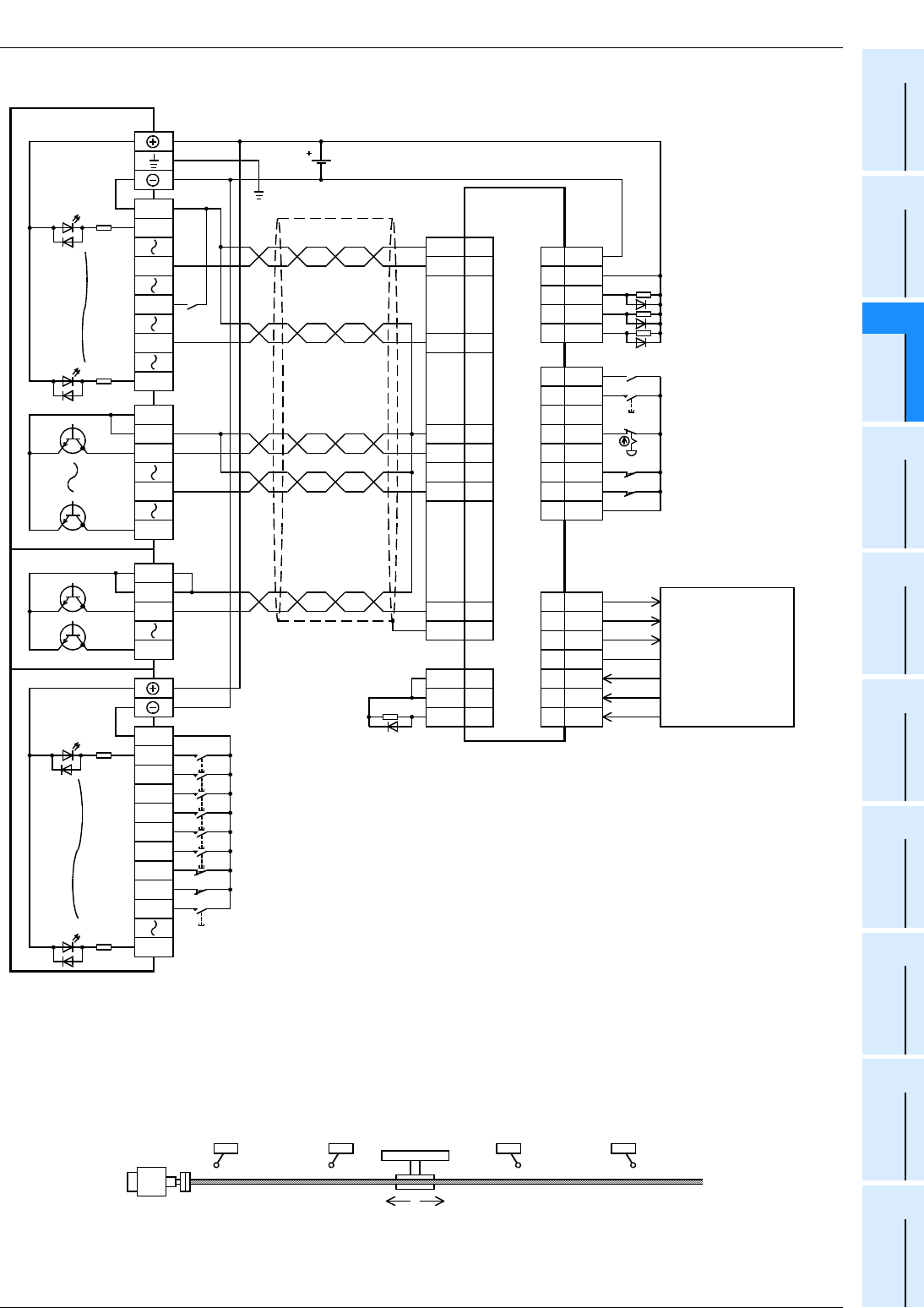
FX
3G
/FX
3U
/FX
3UC
PLC User's Manual - Positioning Control Edition
Example Connection
Appendix 2. MELSERVO-J2 (-Super) Series
Appendix 2-1 Main Unit (Transistor Output)
Apx. - 11
A
Common Items
B
Built-in
Positioning
Functions
Apx.
Example
Connection
2. FX3UC PLC
*1. Be sure to use the class-D grounding method (grounding resistance: 100
Ω
or less).
*2. Near-point signal (DOG)
*3. To ensure safety, use the forward rotation limit switch and the reverse rotation limit switch on both sides: the PLC side and
the servo amplifier side. Note that the limit switches on the PLC side should be activated slightly earlier than the limit
switches on the servo amplifier side.
*4. To detect absolute positions, connect this line to the PLC.
LG
OP
SG
PP
CR
NP
SD
CN1A
SON
RES
EMG
5
14
15
LSP16
LSN17
CN1B
SG20
DO1
ZSP
TLC
4
19
6
SG10
SON5
ABSM
ABSR
8
9
CN1B
SG
COM
10
13
CN1B
ZSP19
TLC6
ALM18
COM
OPC
INP
RD
Plate
1
14
10
3
8
2
9
11
18
19
CN1A
FX
2NC
-16EX
FX
2NC
-16EYT
Refer to Appendix
2.3.1-2.
24V DC
COM
X020
FX
2NC
-16EX
X021
X022
X023
X024
X026
X027
X037
X025
X030
COM1
FX
2NC
-16EYT
Y020
Y027
COM1
DOG
*2
COM
X004
X017
FX
3UC
-32MT/D
X010
X014
X000
COM1
COM1
Y000
Y017
Y004
Photo-
coupler
Photo-
coupler
Class-D
grounding
*1
Zero Point
signal(PG0)
Servo ready
(RD)
Pulse train
CLEAR signal
Positioning
completed(INP)
Zero speed
*4
Torque being controlled
*4
Servo error(ALM)
MR-J2(S)
A
Series servo
amplifier
*4
Connected to the
FX
3UC
if ABS the
instruction(FNC
155) is used.
Servo ON
*4
Reset
Emergency stop
Forward rotation limit 2
*3
Reverse rotation limit 2
*3
Immediate stop command
Zero return command
JOG(+)command
JOG(-)command
Forward rotation positioning command
Forward rotation limit (LSF)
*3
Reverse rotation limit (LSR)
*3
Reverse rotation positioning command
Stop command
Direction
Reverse rotation limit 2
(Servo amplifier side)
Reverse rotation limit 1
(Programmable
controller side)
LSR
Forward rotation limit 2
(Servo amplifier side)
Forward rotation limit 1
(Programmable
controller side)
LSF
Reverse rotation Forward rotation
Servo motor
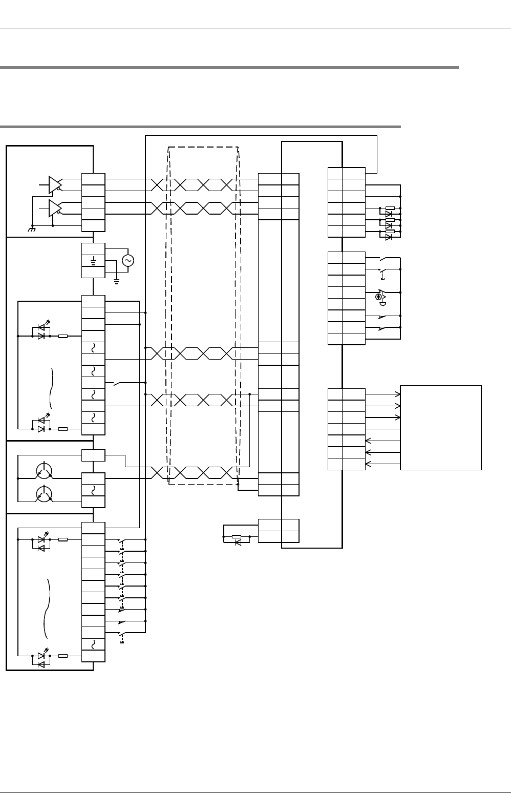
FX
3G
/FX
3U
/FX
3UC
PLC User's Manual - Positioning Control Edition
Example Connection
Appendix 2. MELSERVO-J2 (-Super) Series
Appendix 2-2 High-Speed Output Special Adapter
Apx. - 12
Appendix 2-2 High-Speed Output Special Adapter
To assign the inputs/outputs, refer to the following section.
→ Refer to Section 12.1 of "B. Built-in Positioning Function".
Appendix 2-2-1 Sink Input, Sink Output (Transistor), and Differential Line Driver Output
*1. Be sure to use the class-D grounding method (grounding resistance: 100
Ω
or less).
*2. Near-point signal (DOG)
LG
OP
SG
CR
NP
SD
CN1A
SON
RES
EMG
5
14
15
LSP16
LSN17
CN1B
SG20
DO1
ZSP
TLC
4
19
6
SG10
SON5
ABSM
ABSR
8
9
CN1B
VDD
COM
3
13
CN1B
ZSP19
TLC6
ALM18
COM
INP
RD
Plate
1
14
10
8
2
9
18
19
CN1A
FX
2N
-16EX-ES/UL
FX
2N
-16EYT
Refer to Appendix
2.3.1-1.
COM1
FX
2N
-16EYT
Y020
Y027
Y0/2+
FX
3U
-2HSY-ADP
Y0/2-
SGA
Y4/6+
Y4/6-
SGA
DOG
*2
X004
X017
FX
3U
-32MR/ES
X010
X014
X000
24V
0V
S/S
N
L
100V to
240V AC
PP 3
PG 13
NG 12
S/S
X020
FX
2N
-16EX-ES/UL
X021
X022
X023
X024
X026
X027
X037
X025
X030
SG10
*4
Photo-
coupler
Photo-
coupler
Class-D
grounding
*1
Zero Point
signal(PG0)
Servo ready
(RD)
CLEAR signal
Immediate stop
command
Zero return command
JOG(+)command
JOG(-)command
Forward rotation positioning command
Forward rotation limit (LSF)
*3
Reverse rotation limit (LSR)
*3
Reverse rotation positioning command
Stop command
Positioning
completed(INP)
MR-J2(S)
A
Series servo
amplifier
Zero speed
*5
Torque being controlled
*5
Servo error(ALM)
*5
Connected to the
PLC if the ABS
instruction (FNC
155) is used.
Servo ON
*5
Reset
Emergency stop
Forward rotation limit 2
*3
Reverse rotation limit 2
*3
Epuivalent to
AM26C31
Pulse train
(Forward rotation
pulse train)*
6
Direction signal
(Reverse rotation
pulse train)*
6
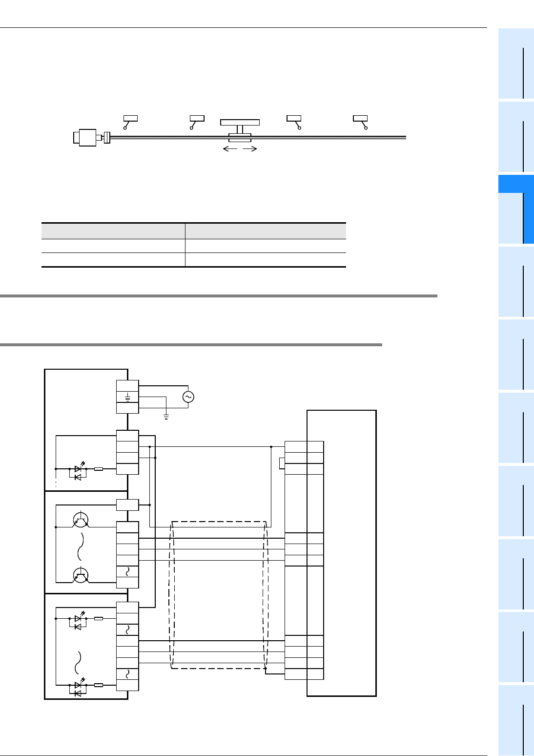
FX
3G
/FX
3U
/FX
3UC
PLC User's Manual - Positioning Control Edition
Example Connection
Appendix 2. MELSERVO-J2 (-Super) Series
Appendix 2-3 Absolute Position Detection (Transistor Output)
Apx. - 13
A
Common Items
B
Built-in
Positioning
Functions
Apx.
Example
Connection
*3. To ensure safety, use the forward rotation limit switch and the reverse rotation limit switch on both sides: the PLC side and
the servo amplifier side. Note that the limit switches on the PLC side should be activated slightly earlier than the limit
switches on the servo amplifier side.
*4. For details on the MR-J2(S) servo amplifier, such as the tolerance for the internal power and operation of the servo
amplifier, refer to the following manual.
→ For details, refer to the servo amplifier manual.
*5. To detect absolute positions, connect this line to the PLC.
*6. Set the pulse output method using the pulse output method setting switch.
Appendix 2-3 Absolute Position Detection (Transistor Output)
To assign the inputs/outputs, refer to the following section.
→ Refer to Section 12.1 of "B. Built-in Positioning"
Appendix 2-3-1 Sink Input and Sink Output
1. FX3U/FX3G PLC
*1. Be sure to use the class-D grounding method (grounding resistance: 100
Ω
or less).
*2. For details on the MR-J2(S) servo amplifier, such as the tolerance for the internal power and operation of the servo
amplifier, refer to the following manual.
→ For details, refer to the servo amplifier manual.
Pulse output method setting switch Pulse output method
FP•RP side Forward/reverse pulse train
PLS•DIR side Pulse train + direction
Reverse rotation limit 2
(Servo amplifier side)
Reverse rotation limit 1
(Programmable
controller side)
LSR
Forward rotation limit 2
(Servo amplifier side)
Forward rotation limit 1
(Programmable
controller side)
LSF
Reverse rotation Forward rotation
Servo motor
FX
3U
-32MT/ES
X000
24V
0V
S/S
N
L100V to 240V AC
COM1
FX
2N
-16EYT
Y020
Y027
Y021
Y022
Y023
SD
Plate
SON
ABSR
ABSM
SG
COM
CN1B
10
13
5
9
8
DO1
TLC
ZSP
4
6
19
S/S
X020
FX
2N
-16EX-ES/UL
X031
X032
X033
X037
VDD 3
*2
Photo-
coupler
Photo-
coupler
Class-D
grounding
*1
ABS(bit0)
ABS(bit1)
Servo-ON
ABS transfer mode
ABS request
Send data ready
MR-J2(S)
A
Series servo
amplifier
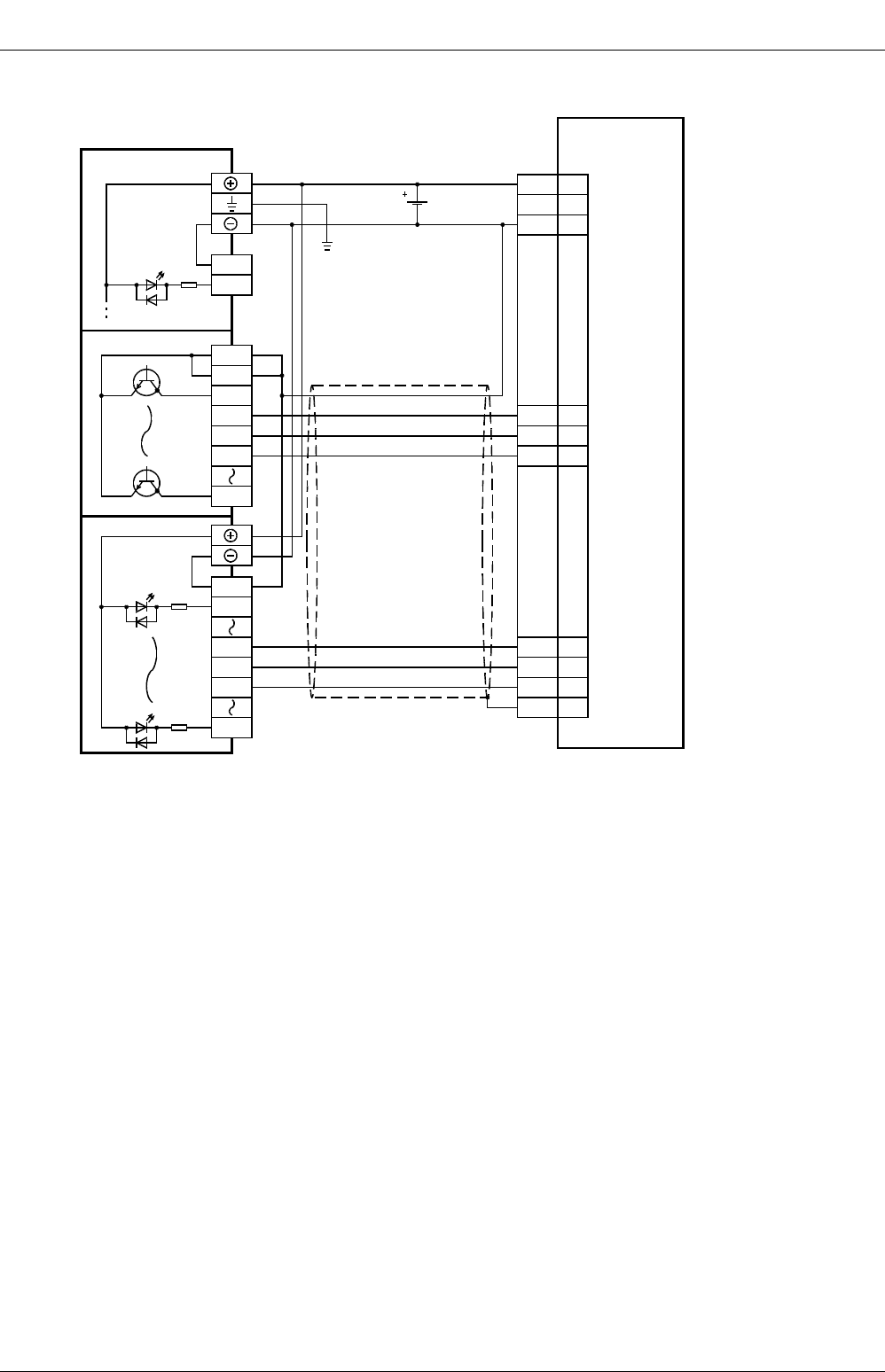
FX
3G
/FX
3U
/FX
3UC
PLC User's Manual - Positioning Control Edition
Example Connection
Appendix 2. MELSERVO-J2 (-Super) Series
Appendix 2-3 Absolute Position Detection (Transistor Output)
Apx. - 14
2. FX3UC PLC
*1. Be sure to use the class-D grounding method (grounding resistance: 100
Ω
or less).
FX
3UC
-32MT/D
SD
Plate
COM1
FX
2NC
-16EYT
Y020
Y027
COM1
Y021
Y022
Y023
COM
X000
COM
X020
FX
2NC
-16EX
X031
X032
X033
X037
SON
ABSR
ABSM
CN1B
SG
COM
10
13
5
9
8
DO1
TLC
ZSP
4
6
19
Photo-
coupler
Photo-
coupler
24V DC
Class-D
grounding
*1
ABS(bit0)
ABS(bit1)
Servo-ON
ABS transfer mode
ABS request
Send data ready
MR-J2(S)
A
Series servo
amplifier
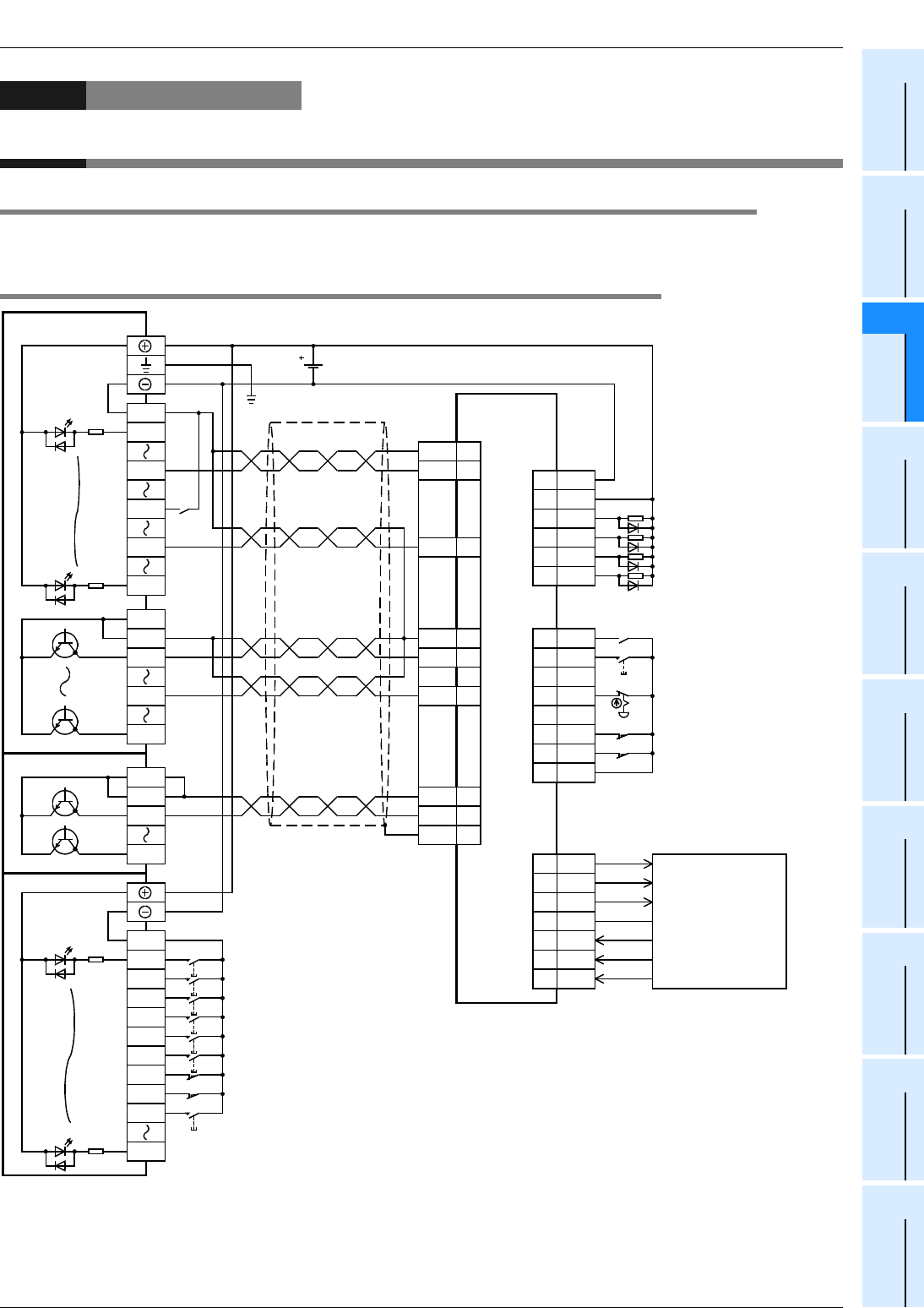
FX
3G
/FX
3U
/FX
3UC
PLC User's Manual - Positioning Control Edition
Example Connection
Appendix 3. MELSERVO-H Series
Appendix 3-1 Main Unit (Transistor Output)
Apx. - 15
A
Common Items
B
Built-in
Positioning
Functions
Apx.
Example
Connection
Appendix 3. MELSERVO-H Series
Appendix 3-1 Main Unit (Transistor Output)
To assign the inputs/outputs, refer to the following section.
→ Refer to Section 12.1 of "B. Built-in Positioning Function".
Appendix 3-1-1 Sink Input and Sink Output
DOG
*2
COM
X004
X017
FX
3UC
-32MT/D
X010
X014
X000
COM1
COM1
Y000
Y017
Y004
LG
OP
SG
PP0
NPO
SD
CN1
28
33
47
18
19
50
SG40
CN1
VIN
PF
ZSP
20
24
23
TLC25
ALM48
SON
RES
EMG
12
15
46
LSP38
LSN39
CN1
SG40
PF
ZSP
TLC
24
23
25
SG16
SON12
D13
D14
44
45
CN1
CR
37
SG 17
RD 49
FX
2NC
-16EX
FX
2NC
-16EYT
Refer to Appendix
3.2.1.
COM
X020
FX
2NC
-16EX
X021
X022
X023
X024
X026
X027
X037
X025
X030
COM1
FX
2NC
-16EYT
Y020
Y027
COM1
Photo-
coupler
Photo-
coupler
24V DC
Class-D
grounding
*1
Zero Point
signal(PG0)
Servo ready
(RD)
Pulse train
CLEAR signal
MR-H
A
Series servo
amplifier
Immediate stop command
Zero return command
JOG(+)command
JOG(-)command
Forward rotation positioning command
Forward rotation limit (LSF)
*3
Reverse rotation limit (LSR)
*3
Reverse rotation positioning command
Stop command
Zero speed
*4
Positioning completed(INP)
*4
Torque being controlled
*4
Servo error(ALM)
*4
Connected to the
FX
3UC
if the ABS
instruction(FNC
155) is used.
Servo ON
*4
Reset
Emergency stop
Forward rotation limit 2
*3
Reverse rotation limit 2
*3
Direction
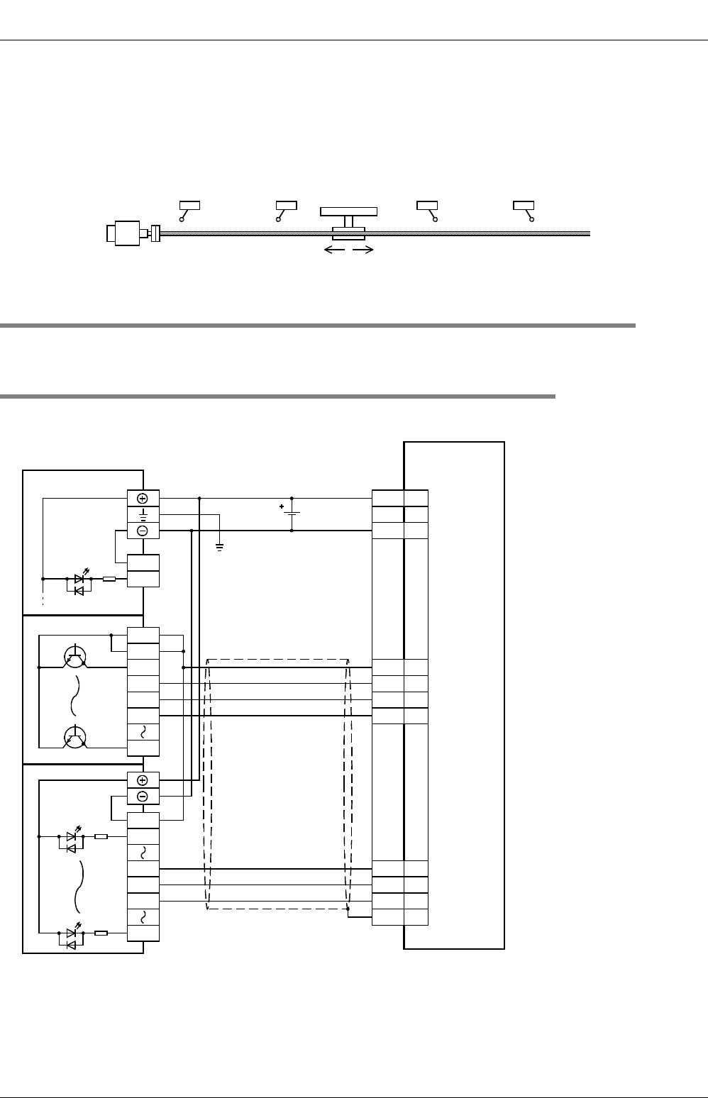
FX
3G
/FX
3U
/FX
3UC
PLC User's Manual - Positioning Control Edition
Example Connection
Appendix 3. MELSERVO-H Series
Appendix 3-2 Absolute Position Detection (Transistor Output)
Apx. - 16
*1. Be sure to use the class-D grounding method (grounding resistance: 100
Ω
or less).
*2. Near-point signal (DOG)
*3. To ensure safety, use the forward rotation limit switch and the reverse rotation limit switch on both sides: the PLC side and
the servo amplifier side. Note that the limit switches on the PLC side should be activated slightly earlier than the limit
switches on the servo amplifier side.
*4. To detect absolute positions, connect this line to the PLC.
Appendix 3-2 Absolute Position Detection (Transistor Output)
To assign the inputs/outputs, refer to the following section.
→ Refer to Section 12.1 of "B. Incorporated Positioning"
Appendix 3-2-1 Sink Input and Sink Output
1. FX3UC PLC
*1. Be sure to use the class-D grounding method (grounding resistance: 100
Ω
or less).
Reverse rotation limit 2
(Servo amplifier side)
Reverse rotation limit 1
(Programmable
controller side)
LSR
Forward rotation limit 2
(Servo amplifier side)
Forward rotation limit 1
(Programmable
controller side)
LSF
Reverse rotation Forward rotation
Servo motor
SD
SG
PF
40
24
VIN 20
SG 16
TLC 25
ZSP 23
SON 12
DI4 45
DI3 44
50
CN1
FX
3UC
-32MT/D
COM1
FX
2NC
-16EYT
Y020
Y27
COM1
Y021
Y022
Y023
COM
X000
COM
X020
FX
2NC
-16EX
X031
X032
X033
X037
Photo-
coupler
Photo-
coupler
24V DC
Class-D
grounding
*1
ABS(bit0)
ABS(bit1)
Servo-ON
ABS transfer mode
ABS request
Send data ready
MR-H
A
Series servo
amplifier
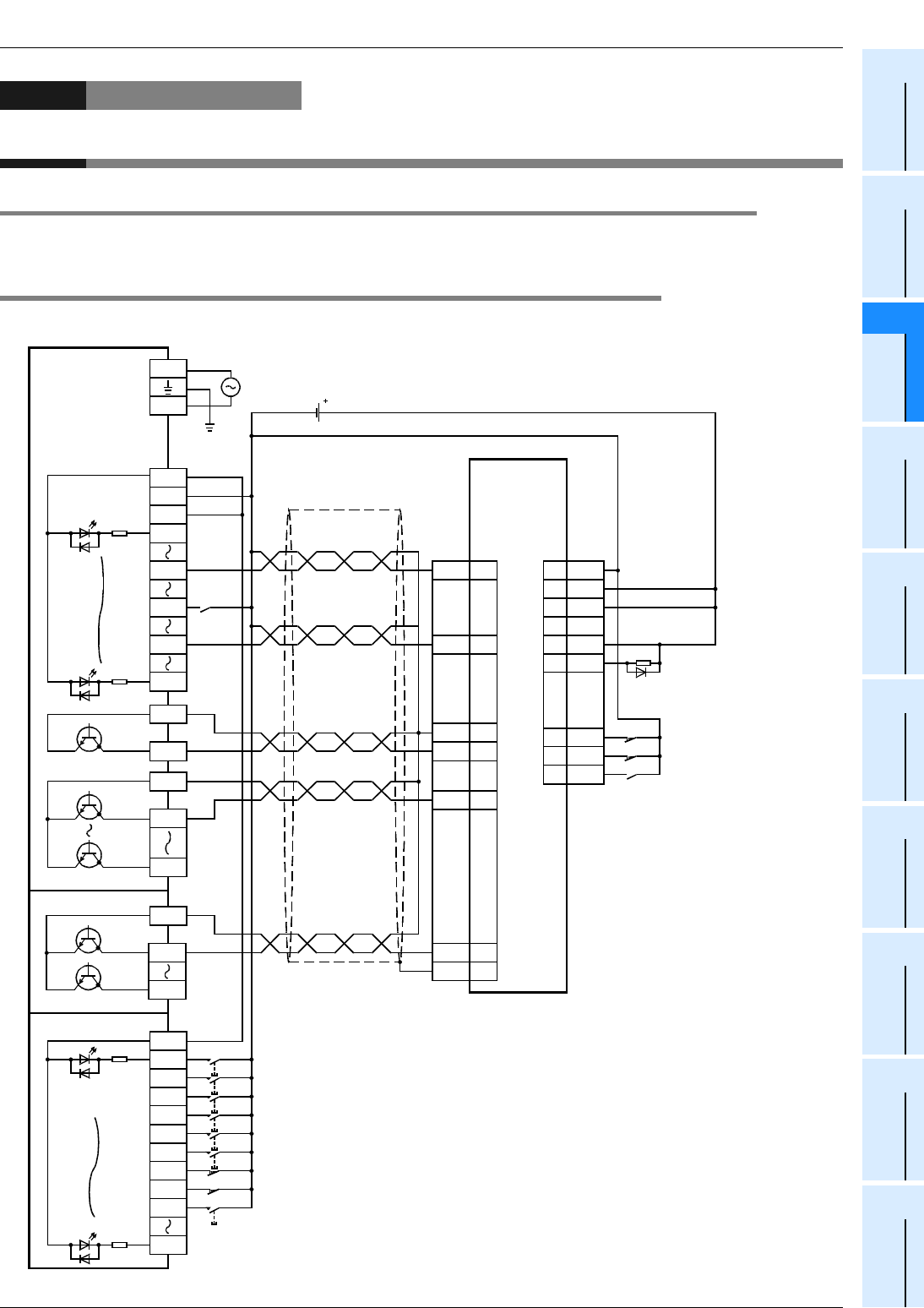
FX
3G
/FX
3U
/FX
3UC
PLC User's Manual - Positioning Control Edition
Example Connection
Appendix 4. MELSERVO-C Series
Appendix 4-1 Main Unit (Transistor Output)
Apx. - 17
A
Common Items
B
Built-in
Positioning
Functions
Apx.
Example
Connection
Appendix 4. MELSERVO-C Series
Appendix 4-1 Main Unit (Transistor Output)
To assign the inputs/outputs, refer to the following section.
→ Refer to Section 12.1 of "B. Built-in Positioning Function".
Appendix 4-1-1 Sink Input and Sink Output
1. FX3U/FX3G PLC
SG
V+
ALM
12
1
2
SON
LSP
LSN
17
15
14
CN1
V2420
OPC19
*3
Servo error(ALM)
Servo ON
Forward rotation limit 2
*4
Reverse rotation limit 2
*4
OP
SG
PP
CN1
4
5
9
NP 7
RD 3
24V DC
CR 13
SD 11
DOG
*2
L
24V
X004
X017
FX
3U
-32MT/ES
X010
X014
X000
COM1
COM2
Y000
Y007
Y004
S/S
X020
FX
2N
-16EX-ES/UL
X021
X022
X023
X024
X026
X027
X037
X025
X030
COM1
FX
2N
-16EYT
Y020
Y027
Photo-
coupler
Photo-
coupler
N
Immediate stop command
Zero return command
JOG(+)command
JOG(-)command
Forward rotation positioning command
Forward rotation limit (LSF)
*4
Reverse rotation limit (LSR)
*4
Reverse rotation positioning command
Stop command
Class-D
grounding
*1
Zero Point
signal(PG0)
Servo ready
(RD)
Pulse train
CLEAR signal
MR-C
A
Series servo
amplifier
Direction
100 to 240V AC
0V
S/S

FX
3G
/FX
3U
/FX
3UC
PLC User's Manual - Positioning Control Edition
Example Connection
Appendix 4. MELSERVO-C Series
Appendix 4-1 Main Unit (Transistor Output)
Apx. - 18
*1. Be sure to use the class-D grounding method (grounding resistance: 100
Ω
or less).
*2. Near-point signal (DOG)
*3. Set the servo amplifier parameter No.21 to "020".
*4. To ensure safety, use the forward rotation limit switch and the reverse rotation limit switch on both sides: the PLC side and
the servo amplifier side. Note that the limit switches on the PLC side should be activated slightly earlier than the limit
switches on the servo amplifier side.
Reverse rotation limit 2
(Servo amplifier side)
Reverse rotation limit 1
(Programmable
controller side)
LSR
Forward rotation limit 2
(Servo amplifier side)
Forward rotation limit 1
(Programmable
controller side)
LSF
Reverse rotation Forward rotation
Servo motor
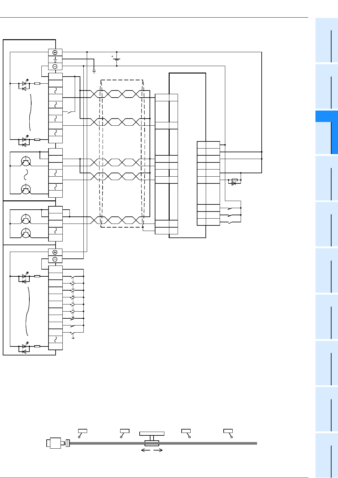
FX
3G
/FX
3U
/FX
3UC
PLC User's Manual - Positioning Control Edition
Example Connection
Appendix 4. MELSERVO-C Series
Appendix 4-1 Main Unit (Transistor Output)
Apx. - 19
A
Common Items
B
Built-in
Positioning
Functions
Apx.
Example
Connection
2. FX3UC PLC
*1. Be sure to use the class-D grounding method (grounding resistance: 100
Ω
or less).
*2. Near-point signal (DOG)
*3. Set the servo amplifier parameter No.21 to "020".
*4. To ensure safety, use the forward rotation limit switch and the reverse rotation limit switch on both sides: the PLC side and
the servo amplifier side. Note that the limit switches on the PLC side should be activated slightly earlier than the limit
switches on the servo amplifier side.
OP
SG
PP
CR
NP
SD
CN1
4
5
9
13
7
11
SG
V+
ALM
12
1
2
SON
LSP
LSN
17
15
14
CN1
V2420
OPC19
RD 3
*3
DOG
*2
COM
X004
X017
FX
3UC
-32MT/D
X010
X014
X000
COM1
COM1
Y000
Y017
Y004
COM
X020
FX
2NC
-16EX
X021
X022
X023
X024
X026
X027
X037
X025
X030
COM1
FX
2NC
-16EYT
Y020
Y27
COM1
Photo-
coupler
Photo-
coupler
Immediate stop command
Zero return command
JOG(+)command
JOG(-)command
Forward rotation positioning command
Forward rotation limit (LSF)
*4
Reverse rotation limit (LSR)
*4
Reverse rotation positioning command
Stop command
24V DC
Class-D
grounding
*1
Zero Point
signal(PG0)
Servo ready
(RD)
Pulse train
CLEAR signal
MR-C
A
Series servo
amplifier
Servo error(ALM)
Servo ON
Forward rotation limit 2
*4
Reverse rotation limit 2
*4
Direction
Reverse rotation limit 2
(Servo amplifier side)
Reverse rotation limit 1
(Programmable
controller side)
LSR
Forward rotation limit 2
(Servo amplifier side)
Forward rotation limit 1
(Programmable
controller side)
LSF
Reverse rotation Forward rotation
Servo motor
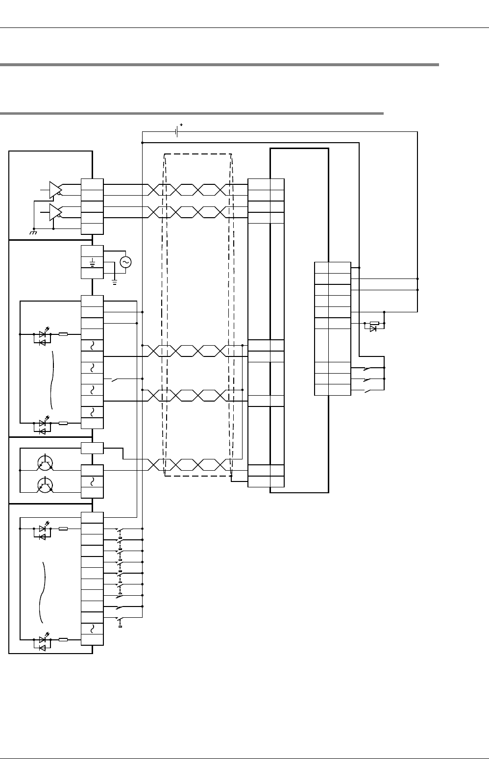
FX
3G
/FX
3U
/FX
3UC
PLC User's Manual - Positioning Control Edition
Example Connection
Appendix 4. MELSERVO-C Series
Appendix 4-2 High-Speed Output Special Adapter
Apx. - 20
Appendix 4-2 High-Speed Output Special Adapter
To assign the inputs/outputs, refer to the following section.
→ Refer to Section 12.1 of "B. Built-in Positioning Function"
Appendix 4-2-1 Sink Input, Sink Output, and Differential Line Driver Output
*1. Be sure to use the class-D grounding method (grounding resistance: 100
Ω
or less).
*2. Near-point signal (DOG)
*3. Set the servo amplifier parameter No.21 to "020".
OP
SG
PP
CR
NP
SD
CN1
4
5
9
13
7
11
SG
V+
ALM
12
1
2
SON
LSP
LSN
17
15
14
CN1
V2420
OPC19
RD 3
*3
PG 10
NG 8
Y0/2+
FX
3U
-2HSY-ADP
Y0/2-
SGA
Y4/6+
Y4/6-
SGA
DOG
*2
X004
X017
FX
3U
-32MR/ES
X010
X014
X000
24V
0V
S/S
N
L
100V to
240V AC
24V DC
COM1
FX
2N
-16EYT
Y020
Y027
S/S
X020
FX
2N
-16EX-ES/UL
X021
X022
X023
X024
X026
X027
X037
X025
X030
Photo-
coupler
Photo-
coupler
Class-D
grounding
*1
Immediate stop command
Zero return command
JOG(+)command
JOG(-)command
Forward rotation positioning command
Forward rotation limit (LSF)
*4
Reverse rotation limit (LSR)
*4
Reverse rotation positioning command
Stop command
Zero Point
signal(PG0)
Servo ready
(RD)
CLEAR signal
MR-C
A
Series servo
amplifier
Servo error(ALM)
Servo ON
Forward rotation limit 2
*4
Reverse rotation limit 2
*4
Epuivalent to
AM26C31
Pulse train
(Forward rotation
pulse train)*
5
Direction signal
(Reverse rotation
pulse train)*
5

FX
3G
/FX
3U
/FX
3UC
PLC User's Manual - Positioning Control Edition
Example Connection
Appendix 4. MELSERVO-C Series
Appendix 4-2 High-Speed Output Special Adapter
Apx. - 21
A
Common Items
B
Built-in
Positioning
Functions
Apx.
Example
Connection
*4. To ensure safety, use the forward rotation limit switch and the reverse rotation limit switch on both sides: the PLC side and
the servo amplifier side. Note that the limit switches on the PLC side should be activated slightly earlier than the limit
switches on the servo amplifier side.
*5. Set the pulse output method using the pulse output method setting switch.
Pulse output method setting switch Pulse output method
FP•RP side Forward/reverse pulse train
PLS•DIR side Pulse train + direction
Reverse rotation limit 2
(Servo amplifier side)
Reverse rotation limit 1
(Programmable
controller side)
LSR
Forward rotation limit 2
(Servo amplifier side)
Forward rotation limit 1
(Programmable
controller side)
LSF
Reverse rotation Forward rotation
Servo motor

FX
3G
/FX
3U
/FX
3UC
PLC User's Manual - Positioning Control Edition
Example Connection
Appendix 4. MELSERVO-C Series
Appendix 4-2 High-Speed Output Special Adapter
Apx. - 22
MEMO

i
FX
3G
/FX
3U
/FX
3UC
PLC User's Manual - Positioning Control Edition
Warranty
Warranty
Please confirm the following product warranty details before using this product.
1. Gratis Warranty Term and Gratis Warranty Range
If any faults or defects (hereinafter "Failure") found to be
the responsibility of Mitsubishi occurs during use of the
product within the gratis warranty term, the product shall be
repaired at no cost via the sales representative or
Mitsubishi Service Company. However, if repairs are
required onsite at domestic or overseas location, expenses
to send an engineer will be solely at the customer's
discretion. Mitsubishi shall not be held responsible for any
re-commissioning, maintenance, or testing on-site that
involves replacement of the failed module.
[Gratis Warranty Term]
The gratis warranty term of the product shall be for one
year after the date of purchase or delivery to a designated
place. Note that after manufacture and shipment from
Mitsubishi, the maximum distribution period shall be six (6)
months, and the longest gratis warranty term after
manufacturing shall be eighteen (18) months. The gratis
warranty term of repair parts shall not exceed the gratis
warranty term before repairs.
[Gratis Warranty Range]
1) The range shall be limited to normal use within the
usage state, usage methods and usage environment,
etc., which follow the conditions and precautions, etc.,
given in the instruction manual, user's manual and
caution labels on the product.
2) Even within the gratis warranty term, repairs shall be
charged for in the following cases.
a) Failure occurring from inappropriate storage or
handling, carelessness or negligence by the user.
Failure caused by the user's hardware or software
design.
b) Failure caused by unapproved modifications, etc.,
to the product by the user.
c) When the Mitsubishi product is assembled into a
user's device, Failure that could have been
avoided if functions or structures, judged as
necessary in the legal safety measures the user's
device is subject to or as necessary by industry
standards, had been provided.
d) Failure that could have been avoided if
consumable parts (battery, backlight, fuse, etc.)
designated in the instruction manual had been
correctly serviced or replaced.
e) Relay failure or output contact failure caused by
usage beyond the specified Life of contact
(cycles).
f) Failure caused by external irresistible forces such
as fires or abnormal voltages, and failure caused
by force majeure such as earthquakes, lightning,
wind and water damage.
g) Failure caused by reasons unpredictable by
scientific technology standards at time of
shipment from Mitsubishi.
h) Any other failure found not to be the responsibility
of Mitsubishi or that admitted not to be so by the
user.
2. Onerous repair term after discontinuation of
production
1) Mitsubishi shall accept onerous product repairs for
seven (7) years after production of the product is
discontinued.
Discontinuation of production shall be notified with
Mitsubishi Technical Bulletins, etc.
2) Product supply (including repair parts) is not available
after production is discontinued.
3. Overseas service
Overseas, repairs shall be accepted by Mitsubishi's local
overseas FA Center. Note that the repair conditions at
each FA Center may differ.
4. Exclusion of loss in opportunity and secondary
loss from warranty liability
Regardless of the gratis warranty term, Mitsubishi shall not
be liable for compensation of damages caused by any
cause found not to be the responsibility of Mitsubishi, loss
in opportunity, lost profits incurred to the user or third
person by Failures of Mitsubishi products, special
damages and secondary damages whether foreseeable or
not , compensation for accidents, and compensation for
damages to products other than Mitsubishi products,
replacement by the user, maintenance of on-site
equipment, start-up test run and other tasks.
5. Changes in product specifications
The specifications given in the catalogs, manuals or
technical documents are subject to change without prior
notice.
6. Product application
1) In using the Mitsubishi MELSEC programmable logic
controller, the usage conditions shall be that the
application will not lead to a major accident even if any
problem or fault should occur in the programmable
logic controller device, and that backup and fail-safe
functions are systematically provided outside of the
device for any problem or fault.
2) The Mitsubishi programmable logic controller has
been designed and manufactured for applications in
general industries, etc. Thus, applications in which the
public could be affected such as in nuclear power
plants and other power plants operated by respective
power companies, and applications in which a special
quality assurance system is required, such as for
Railway companies or Public service purposes shall
be excluded from the programmable logic controller
applications.
In addition, applications in which human life or
property that could be greatly affected, such as in
aircraft, medical applications, incineration and fuel
devices, manned transportation, equipment for
recreation and amusement, and safety devices, shall
also be excluded from the programmable logic
controller range of applications.
However, in certain cases, some applications may be
possible, providing the user consults their local
Mitsubishi representative outlining the special
requirements of the project, and providing that all
parties concerned agree to the special circumstances,
solely at the users discretion.

ii
FX
3G
/FX
3U
/FX
3UC
PLC User's Manual - Positioning Control Edition
Revised History
Revised History
Date Revision Description
7/2005 A First Edition
2/2006 B • The transistor output for FX3U Series was added.
- A.Common items
(Subsection 1.2.1 and 1.2.2, Section 2.1 and Subsection 3.1.1).
- B.Built-in positioning function
(Section 1.1, Subsection 1.5.2 and 1.5.3, Section 2.3, Subsection 2.5.1, Section
4.9, Subsection 6.3.1, 8.2.1 and 8.3.1, Section 9.1 and 10.1).
- Appendix:Example connection
(Appendix 1-1-1, 1-3, 2-1-1 and 4-1-1).
•FX
3U-20SSC-H was added.
- A.Common items
(Subsection 1.2.1, Section 2.1, Section 2.2, Subsection 3.1.3 and Section 3.2)
• Other
- Section-number changed Revision A (Revision B)
A.Common items: Subsection 3.1.3 (3.1.4)
B. Built-in positioning function: Subsection 2.5.1 (2.5.2) to 2.5.2 (2.5.3)
- Correction of errors
11/2007 C • FX3UC (D, DSS) Series PLC added.
• Correction of errors
11/2008 D • FX3G Series PLC added.
3/2009 E • The transistor output (source type) for FX3G Series was added.
• Explanation corrections for manufacturer’s serial number.

HEAD OFFICE: TOKYO BUILDING, 2-7-3 MARUNOUCHI, CHIYODA-KU, TOKYO 100-8310, JAPAN
HIMEJI WORKS: 840, CHIYODA CHO, HIMEJI, JAPAN
JY997D16801E
(MEE)
Effective March 2009
Specifications are subject to change without notice.
USER'S MANUAL - Positioning Control Edition
FX
3G
/FX
3U
/FX
3UC
SERIES PROGRAMMABLE CONTROLLERS
MODEL FX3U-U-POS-E
MODEL CODE 09R620
