Mitsubishi HG SR MR/HG KR/HG SR/HG JR/HG RR/HG UR/HG AK SERVO MOTOR INSTRUCTION MANUAL(Vol.3) User Manual To The 0e2368a2 827f 424d 8aed Ce513320e7fa
User Manual: Mitsubishi HG-SR to the manual
Open the PDF directly: View PDF ![]() .
.
Page Count: 378 [warning: Documents this large are best viewed by clicking the View PDF Link!]
- Safety Instructions
- DISPOSAL OF WASTE
- U.S. customary units
- CONTENTS
- 1. INTRODUCTION
- 2. INSTALLATION
- 3. CONNECTORS USED FOR SERVO MOTOR WIRING
- 4. CONNECTION OF SERVO AMPLIFIER AND SERVO MOTOR
- 5. WIRING OPTION
- 6. HG-MR SERIES/HG-KR SERIES
- 6.1 Model code definition
- 6.2 Combination list of servo motors and servo amplifiers
- 6.3 Standard specifications
- 6.4 Electromagnetic brake characteristics
- 6.5 Servo motors with special shafts
- 6.6 Geared servo motors
- 6.7 Mounting connectors
- 6.8 Dimensions
- 6.8.1 Standard (without electromagnetic brake and reducer)
- 6.8.2 With an electromagnetic brake
- 6.8.3 For general industrial machine with a reducer (without an electromagnetic brake)
- 6.8.4 For general industrial machine with a reducer (with an electromagnetic brake)
- 6.8.5 With flange-output type reducer for high precision applications, flange mounting (without an electromagnetic brake)
- 6.8.6 With flange-output type reducer for high precision applications, flange mounting (with an electromagnetic brake)
- 6.8.7 With shaft-output type reducer for high precision applications, flange mounting (without an electromagnetic brake)
- 6.8.8 With shaft-output type reducer for high precision applications, flange mounting (with an electromagnetic brake)
- 7. HG-SR SERIES
- 7.1 Model code definition
- 7.2 Combination list of servo motors and servo amplifiers
- 7.3 Standard specifications
- 7.4 Electromagnetic brake characteristics
- 7.5 Servo motors with special shafts
- 7.6 Geared servo motors
- 7.7 Dimensions
- 7.7.1 Standard (without electromagnetic brake and reducer)
- 7.7.2 With an electromagnetic brake
- 7.7.3 For general industrial machine with a reducer (without an electromagnetic brake)
- 7.7.4 For general industrial machine with a reducer (with an electromagnetic brake)
- 7.7.5 For general industrial machine with a reducer (foot-mounting/without an electromagnetic brake)
- 7.7.6 For general industrial machine with a reducer (foot-mounting/with an electromagnetic brake)
- 7.7.7 With flange-output type reducer for high precision applications, flange mounting (without an electromagnetic brake)
- 7.7.8 With flange-output type reducer for high precision applications, flange mounting (with an electromagnetic brake)
- 7.7.9 With shaft-output type reducer for high precision applications, flange mounting (without an electromagnetic brake)
- 7.7.10 With shaft-output type reducer for high precision applications, flange mounting (with an electromagnetic brake)
- 8. HG-JR SERIES
- 9. HG-RR SERIES
- 10. HG-UR SERIES
- 11. HG-AK SERIES
- APPENDIX
- App. 1 Servo motor ID codes
- App. 2 Manufacturer list
- App. 3 Compliance with the CE marking
- App. 4 Compliance with UL/CSA standard
- App. 5 Calculation methods for designing
- App. 6 Selection example of servo motor power cable
- App. 7 Crimping connector for CNP3_
- App. 8 Connector dimensions
- App. 9 HG-JR22K1M(4) appearance change
- REVISION
- Country/Region
- Warranty

SH (NA) 030113-J (1504) MEE Printed in Japan Specifications are subject to change without notice.
This Instruction Manual uses recycled paper.
MODEL
MODEL
CODE
General-Purpose AC Servo
SERVO MOTOR INSTRUCTION MANUAL (Vol. 3)
HEAD OFFICE : TOKYO BLDG MARUNOUCHI TOKYO 100-8310
MODEL
HG-MR
HG-KR
HG-SR
HG-JR
HG-RR
HG-UR
HG-AK
SERVO MOTOR INSTRUCTION MANUAL (Vol. 3)
1CW949
MOTOR INSTRUCTIONMANUAL(3SYU)
J
J
A - 1
Safety Instructions
Please read the instructions carefully before using the equipment.
Do not attempt to install, operate, maintain or inspect the equipment until you have read through this
Instruction Manual and appended documents carefully and can use the equipment correctly. Do not use the
equipment until you have a full knowledge of the equipment, safety information and instructions.
In this Instruction Manual, the safety instruction levels are classified into "WARNING" and "CAUTION".
WARNING
Indicates that incorrect handling may cause hazardous conditions,
resulting in death or severe injury.
CAUTION Indicates that incorrect handling may cause hazardous conditions,
resulting in medium or slight injury to personnel or may cause physical
damage.
Note that the CAUTION level may lead to a serious consequence according to conditions.
Please follow the instructions of both levels because they are important to personnel safety.
What must not be done and what must be done are indicated by the following diagrammatic symbols.
Indicates what must not be done. For example, "No Fire" is indicated by .
Indicates what must be done. For example, grounding is indicated by .
In this Instruction Manual, instructions at a lower level than the above, instructions for other functions, and so
on are classified into "POINT".
After reading this Instruction Manual, keep it accessible to the operator.
A - 2
1. To prevent electric shock, note the following
WARNING
Before wiring and inspections, turn off the power and wait for 15 minutes or more (20 minutes or more for
converter unit and drive unit) until the charge lamp turns off. Then, confirm that the voltage between P+
and N- (L+ and L- for converter unit and drive unit) is safe with a voltage tester and others. Otherwise, an
electric shock may occur. In addition, when confirming whether the charge lamp is off or not, always
confirm it from the front of the servo amplifier (converter unit).
Ground the servo motor securely.
Any person who is involved in wiring and inspection should be fully competent to do the work.
Do not attempt to wire the servo motor until they have been installed. Otherwise, it may cause an electric
shock.
The cables should not be damaged, stressed, loaded, or pinched. Otherwise, it may cause an electric
shock.
To avoid an electric shock, insulate the connections of the power supply terminals.
2. To prevent fire, note the following
CAUTION
Install the servo motor on incombustible material. Installing it directly or close to combustibles will lead to
a fire.
Provide an adequate protection to prevent screws and other conductive matter, oil and other combustible
matter from entering the servo motor.
3. To prevent injury, note the following
CAUTION
Only the voltage specified in the Instruction Manual should be applied to each terminal. Otherwise, a
burst, damage, etc. may occur.
Connect cables to the correct terminals. Otherwise, a burst, damage, etc. may occur.
Ensure that polarity (+/-) is correct. Otherwise, a burst, damage, etc. may occur.
The servo motor, etc. may be hot while power is on or for some time after power-off. Take safety
measures, e.g. provide covers, to prevent accidental contact of hands and parts (cables, etc.) with them.
The surface temperature of the servo motor may exceed 100 ˚C depending on its mounting and
operating conditions.
During operation, never touch the rotor of the servo motor. Otherwise, it may cause injury.
4. Additional instructions
The following instructions should also be fully noted. Incorrect handling may cause a malfunction, injury,
electric shock, etc.
(1) Transportation and installation
CAUTION
Transport the products correctly according to their mass.
Use the eyebolt of the servo motor for the transportation purpose only. Do not use the eyebolts to
transport the servo motor when it is mounted on a machine.
A - 3
CAUTION
Stacking in excess of the specified number of product packages is not allowed.
Do not carry the servo motor by holding the cables, shaft, encoder, or connector.
Install the servo motor in a load-bearing place in accordance with the Instruction Manual.
Do not get on or put heavy load on the equipment.
The equipment must be installed in the specified direction.
Do not install or operate the servo motor which have been damaged or have any parts missing.
Do not block intake and exhaust areas of the servo motor with a cooling fan. Otherwise, it may cause a
malfunction.
Do not drop or strike the servo motor. Isolate it from all impact loads.
Securely fix the servo motor to the machine. If being attached insecurely, the servo motor may come off
during operation.
The geared servo motor must be installed in the specified direction to prevent oil leakage.
When handling the servo motor, be careful about the edged parts such as the corners of the servo motor.
Be sure to measure the motor vibration level with the servo motor mounted to the machine when
checking the vibration level. A great vibration may cause the early damage of a bearing, encoder, brake,
and reducer. The great vibration may also cause the poor connector connection or bolt looseness.
For the gain adjustment at the equipment startup, check the torque waveform and the speed waveform
with a measurement device, and then check that no vibration occurs. If the vibration occurs due to high
gain, the vibration may cause the early damage of the servo motor.
Take safety measures, e.g. provide covers, to prevent accidental access to the rotor of the servo motor
during operation.
Never hit the servo motor or shaft, especially when coupling the servo motor to the machine. Otherwise,
the encoder may malfunction.
Do not subject the servo motor shaft to more than the permissible load. Otherwise, the shaft may break.
When you keep or use the equipment, please fulfill the following environment.
Item Environment
Ambient temperature Operation 0 °C to 40 °C (non-freezing)
Storage -15 °C to 70 °C (non-freezing)
Ambient humidity Operation 80 %RH or less (non-condensing)
Storage 90 %RH or less (non-condensing)
Ambience Indoors (no direct sunlight), free from corrosive
gas, flammable gas, oil mist, dust, and dirt
Altitude Max. 1000 m above sea level
Vibration resistance
(Note)
HG-MR Series/HG-KR Series/HG-AK Series X, Y: 49 m/s2
HG-SR51/HG-SR81/HG-SR52(4)/
HG-SR102(4)/HG-SR152(4)/HG-JR53(4)/
HG-JR73(4)/HG-JR103(4)/HG-JR153(4)/
HG-JR203(4)/HG-JR353(4)/HG-JR503(4)/
HG-JR701M(4)/HG-JR11K1M(4)/
HG-JR15K1M(4)/HG-JR22K1M(4)/
HG-JR30K1M(4)/HG-JR37K1M(4)/
HG-JR601(4)/HG-JR801(4)/HG-JR12K1(4)/
HG-JR15K1(4)/HG-JR20K1(4)/HG-JR25K1(4)/
HG-RR Series/HG-UR72/HG-UR152
X, Y: 24.5 m/s2
HG-SR121/HG-SR201/HG-SR202(4)/
HG-SR352(4)/HG-UR202/HG-UR352/HG-UR502 X: 24.5 m/s2 Y: 49 m/s2
HG-SR301/HG-SR421/HG-SR502(4)/
HG-SR702(4)/HG-JR703(4)/HG-JR903(4) X: 24.5 m/s2 Y: 29.4 m/s2
HG-JR45K1M4/HG-JR55K1M4/
HG-JR30K1(4)/HG-JR37K1(4) X: 9.8 m/s2 Y: 9.8 m/s2
Note. Except the geared servo motor.
A - 4
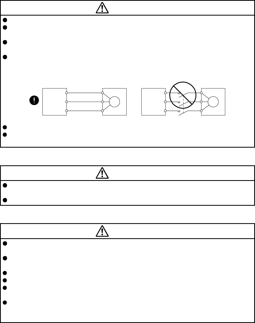
(2) Wiring
CAUTION
Wire the equipment correctly and securely. Otherwise, the servo motor may operate unexpectedly.
Do not install a power capacitor, surge killer, or radio noise filter (FR-BIF-(H) option) on the servo
amplifier (converter unit) output side.
To avoid a malfunction, connect the wires to the correct phase terminals (U, V, and W) of the servo
amplifier (converter unit) and servo motor.
Connect the servo amplifier (converter unit) power output (U, V, and W) to the servo motor power input
(U, V, and W) directly. Do not let a magnetic contactor, etc. intervene. Otherwise, it may cause a
malfunction.
U
Servo motor
M
V
W
U
V
W
U
M
V
W
U
V
W
Servo amplifie
r
(converter unit) Servo motor
Servo amplifier
(converter unit)
Do not connect AC power supply directly to the servo motor. Otherwise, it may cause a malfunction.
When the cable is not tightened enough to the terminal block, the cable or terminal block may generate
heat because of the poor contact. Be sure to tighten the cable with specified torque.
(3) Test run and adjustment
CAUTION
Before operation, check the parameter settings. Improper settings may cause some machines to operate
unexpectedly.
Never adjust or change the parameter values extremely as it will make operation unstable.
(4) Usage
CAUTION
Provide an external emergency stop circuit to ensure that operation can be stopped and power switched
off immediately.
Do not scratch the coated surface with hard objects nor clean the coated surface with an organic solvent.
Doing so may scuff the surface.
Do not disassemble, repair, or modify the equipment.
Use the servo amplifier (converter unit) with the specified servo motor.
The electromagnetic brake on the servo motor is designed to hold the motor shaft and should not be
used for ordinary braking.
For such reasons as service life and mechanical structure (e.g. where a ball screw and the servo motor
are coupled via a timing belt), the electromagnetic brake may not hold the motor shaft. To ensure safety,
install a stopper on the machine side.
A - 5
(5) Corrective actions
CAUTION
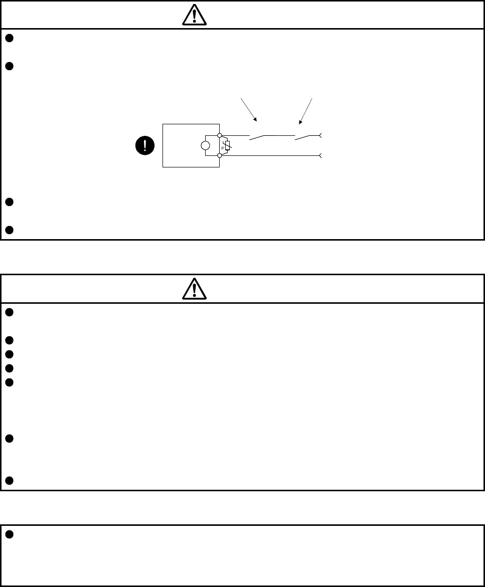
When it is assumed that a hazardous condition may occur due to a power failure or product malfunction,
use a servo motor with an electromagnetic brake or external brake to prevent the condition.
Configure an electromagnetic brake circuit so that it is activated also by an external EMG stop switch.
Servo motor
Electromagnetic brake
B
RA
Contacts must be opened
with the EMG stop switch.
Contacts must be opened when ALM
(Malfunction) or MBR (Electromagnetic
brake interlock) turns off.
24 V DC
When any alarm has occurred, eliminate its cause, ensure safety, and deactivate the alarm before
restarting operation.
Provide an adequate protection to prevent unexpected restart after an instantaneous power failure.
(6) Storage
CAUTION
Note the followings when storing the servo motor for an extended period of time (guideline: three or more
months).
Always store the servo motor indoors in a clean and dry place.
If it is stored in a dusty or damp place, make adequate provision, e.g. cover the whole product.
If the insulation resistance of the winding decreases, check how to store the equipment.
Though the servo motor is rust-proofed before shipment using paint or rust prevention oil, rust may be
produced depending on the storage conditions or storage period.
If the servo motor is to be stored for longer than six months, apply rust prevention oil again especially to
the machined surfaces of the shaft, etc.
Before using the product after storage for an extended period of time, hand-turn the servo motor output
shaft to confirm that nothing is wrong with the servo motor. When the servo motor is equipped with an
electromagnetic brake, check it after releasing the electromagnetic brake with the brake power supply.
When the product has been stored for an extended period of time, contact your local sales office.
(7) General instruction
To illustrate details, the equipment in the diagrams of this Instruction Manual may have been drawn
without covers and safety guards. When the equipment is operated, the covers and safety guards must
be installed as specified. Operation must be performed in accordance with this Specifications and
Instruction Manual.
A - 6
DISPOSAL OF WASTE
Please dispose a servo motor and other options according to your local laws and regulations.
«U.S. customary units»
U.S. customary units are not shown in this manual. Convert the values if necessary according to the
following table.
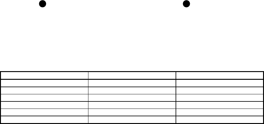
Quantity SI (metric) unit U.S. customary unit
Mass 1 [kg] 2.2046 [lb]
Length 1 [mm] 0.03937 [inch]
Torque 1 [N•m] 141.6 [oz•inch]
Moment of inertia 1 [(× 10-4 kg•m2)] 5.4675 [oz•inch2]
Load (thrust load/axial load) 1 [N] 0.2248 [lbf]
Temperature N [°C] × 9/5 + 32 N [°F]

1
CONTENTS
1. INTRODUCTION 1- 1 to 1- 8
1.1 Rating plate ....................................................................................................................................... 1- 1
1.2 Parts identification ............................................................................................................................. 1- 2
1.3 Electromagnetic brake ...................................................................................................................... 1- 3
1.4 Servo motor shaft shapes ................................................................................................................. 1- 5
1.5 Servo motor with functional safety .................................................................................................... 1- 6
2. INSTALLATION 2- 1 to 2- 6
2.1 Mounting direction............................................................................................................................. 2- 2
2.2 Cooling fan ........................................................................................................................................ 2- 2
2.3 Load remove precautions ................................................................................................................. 2- 3
2.4 Permissible load for the shaft ........................................................................................................... 2- 4
2.5 Protection from oil and water ............................................................................................................ 2- 4
2.6 Cable ................................................................................................................................................. 2- 5
2.7 Servo motor with oil seal ................................................................................................................... 2- 5
2.8 Inspection items ................................................................................................................................ 2- 5
2.9 Parts having service lives ................................................................................................................. 2- 6
2.10 Machine accuracies ........................................................................................................................ 2- 6
3. CONNECTORS USED FOR SERVO MOTOR WIRING 3- 1 to 3-12
3.1 Selection of connectors .................................................................................................................... 3- 1
3.2 Wiring connectors (connector configurations A/B/C) ........................................................................ 3- 5
3.3 Wiring connectors (connector configurations D/E/F/G/H) ................................................................ 3- 6
3.4 Wiring connectors (connector configurations J/K/L/M/N/P/Q) ......................................................... 3-10
4. CONNECTION OF SERVO AMPLIFIER AND SERVO MOTOR 4- 1 to 4-26
4.1 Connection instructions .................................................................................................................... 4- 2
4.2 Wiring ................................................................................................................................................ 4- 3
4.2.1 HG-MR series/HG-KR series servo motor ................................................................................. 4- 3
4.2.2 HG-SR series/HG-JR series/HG-RR series/HG-UR series servo motor ................................... 4- 8
4.2.3 HG-AK series servo motor ........................................................................................................ 4-14
4.3 Selection example of wires .............................................................................................................. 4-16
4.4 Servo amplifier terminal section ....................................................................................................... 4-20
5. WIRING OPTION 5- 1 to 5-34
5.1 Cable/connector sets ........................................................................................................................ 5- 1
5.1.1 Combinations of cable/connector sets ....................................................................................... 5- 2
5.1.2 Cable and connector list ............................................................................................................. 5- 4
5.2 Encoder cable/connector sets ......................................................................................................... 5-10
5.3 Servo motor power cable ................................................................................................................. 5-27
5.4 Servo motor power cable (for HG-AK series) .................................................................................. 5-29
5.5 Electromagnetic brake cable ........................................................................................................... 5-30
5.6 Wires for option cables .................................................................................................................... 5-32

2
6. HG-MR SERIES/HG-KR SERIES 6- 1 to 6-58
6.1 Model code definition ........................................................................................................................ 6- 1
6.2 Combination list of servo motors and servo amplifiers ..................................................................... 6- 2
6.3 Standard specifications ..................................................................................................................... 6- 3
6.3.1 Standard specifications list......................................................................................................... 6- 3
6.3.2 Torque characteristics ................................................................................................................ 6- 5
6.4 Electromagnetic brake characteristics .............................................................................................. 6- 6
6.5 Servo motors with special shafts ...................................................................................................... 6- 7
6.5.1 Key shaft (with 2 round end key) ............................................................................................... 6- 7
6.5.2 D cut shaft .................................................................................................................................. 6- 7
6.6 Geared servo motors ........................................................................................................................ 6- 8
6.6.1 For general industrial machines (G1) ......................................................................................... 6- 8
6.6.2 For high precision applications (G5/G7) ................................................................................... 6-11
6.7 Mounting connectors ....................................................................................................................... 6-14
6.8 Dimensions ...................................................................................................................................... 6-15
6.8.1 Standard (without electromagnetic brake and reducer) ............................................................ 6-15
6.8.2 With an electromagnetic brake ................................................................................................. 6-18
6.8.3 For general industrial machine with a reducer (without an electromagnetic brake) ................. 6-21
6.8.4 For general industrial machine with a reducer (with an electromagnetic brake) ...................... 6-28
6.8.5 With flange-output type reducer for high precision applications, flange mounting (without an
electromagnetic brake) .............................................................................................................. 6-34
6.8.6 With flange-output type reducer for high precision applications, flange mounting (with an
electromagnetic brake) .............................................................................................................. 6-40
6.8.7 With shaft-output type reducer for high precision applications, flange mounting (without an
electromagnetic brake) .............................................................................................................. 6-46
6.8.8 With shaft-output type reducer for high precision applications, flange mounting (with an
electromagnetic brake) .............................................................................................................. 6-52
7. HG-SR SERIES 7- 1 to 7-96
7.1 Model code definition ........................................................................................................................ 7- 1
7.2 Combination list of servo motors and servo amplifiers ..................................................................... 7- 2
7.3 Standard specifications ..................................................................................................................... 7- 3
7.3.1 Standard specifications list......................................................................................................... 7- 3
7.3.2 Torque characteristics ................................................................................................................ 7- 6
7.4 Electromagnetic brake characteristics .............................................................................................. 7- 8
7.5 Servo motors with special shafts ...................................................................................................... 7- 9
7.6 Geared servo motors ....................................................................................................................... 7-10
7.6.1 For general industrial machines (G1/G1H) ............................................................................... 7-10
7.6.2 For high precision applications (G5/G7) ................................................................................... 7-14
7.7 Dimensions ...................................................................................................................................... 7-17
7.7.1 Standard (without electromagnetic brake and reducer) ............................................................ 7-17
7.7.2 With an electromagnetic brake ................................................................................................. 7-20
7.7.3 For general industrial machine with a reducer (without an electromagnetic brake) ................. 7-27
7.7.4 For general industrial machine with a reducer (with an electromagnetic brake) ...................... 7-37
7.7.5 For general industrial machine with a reducer (foot-mounting/without an
electromagnetic brake) ............................................................................................................ 7-47
7.7.6 For general industrial machine with a reducer (foot-mounting/with an
electromagnetic brake) .............................................................................................................. 7-57

3
7.7.7 With flange-output type reducer for high precision applications, flange mounting (without an
electromagnetic brake) .............................................................................................................. 7-68
7.7.8 With flange-output type reducer for high precision applications, flange mounting (with an
electromagnetic brake) .............................................................................................................. 7-75
7.7.9 With shaft-output type reducer for high precision applications, flange mounting (without an
electromagnetic brake) .............................................................................................................. 7-82
7.7.10 With shaft-output type reducer for high precision applications, flange mounting (with an
electromagnetic brake) ........................................................................................................... 7-89
8. HG-JR SERIES 8- 1 to 8-46
8.1 Model designation ............................................................................................................................. 8- 1
8.2 Combination list of servo motors and servo amplifiers/drive units ................................................... 8- 2
8.3 Standard specifications ..................................................................................................................... 8- 8
8.3.1 Standard specifications list......................................................................................................... 8- 8
8.3.2 Torque characteristics ............................................................................................................... 8-15
8.4 Electromagnetic brake characteristics ............................................................................................. 8-19
8.5 Servo motors with special shafts ..................................................................................................... 8-20
8.6 Oil seal ............................................................................................................................................. 8-21
8.7 Cooling fan ....................................................................................................................................... 8-21
8.8 Dimensions ...................................................................................................................................... 8-22
8.8.1 Terminal box detail diagram ...................................................................................................... 8-22
8.8.2 Standard (without an electromagnetic brake) ........................................................................... 8-23
8.8.3 With an electromagnetic brake ................................................................................................. 8-37
9. HG-RR SERIES 9- 1 to 9-12
9.1 Model designation ............................................................................................................................. 9- 1
9.2 Combination list of servo motors and servo amplifiers ..................................................................... 9- 1
9.3 Standard specifications ..................................................................................................................... 9- 2
9.3.1 Standard specifications list......................................................................................................... 9- 2
9.3.2 Torque characteristics ................................................................................................................ 9- 4
9.4 Electromagnetic brake characteristics .............................................................................................. 9- 5
9.5 Servo motors with special shafts ...................................................................................................... 9- 6
9.6 Oil seal .............................................................................................................................................. 9- 6
9.7 Dimensions ....................................................................................................................................... 9- 7
9.7.1 Standard (without an electromagnetic brake) ............................................................................ 9- 7
9.7.2 With an electromagnetic brake .................................................................................................. 9- 9
10. HG-UR SERIES 10- 1 to 10-12
10.1 Model designation .......................................................................................................................... 10- 1
10.2 Combination list of servo motors and servo amplifiers .................................................................. 10- 1
10.3 Standard specifications .................................................................................................................. 10- 2
10.3.1 Standard specifications list ...................................................................................................... 10- 2
10.3.2 Torque characteristics ............................................................................................................. 10- 4
10.4 Electromagnetic brake characteristics ........................................................................................... 10- 5
10.5 Servo motors with special shafts ................................................................................................... 10- 6
10.6 Oil seal ........................................................................................................................................... 10- 6
10.7 Dimensions .................................................................................................................................... 10- 7
10.7.1 Standard (without an electromagnetic brake) ......................................................................... 10- 7

4
10.7.2 With an electromagnetic brake ................................................................................................ 10- 9
11. HG-AK SERIES 11- 1 to 11-14
11.1 Model designation .......................................................................................................................... 11- 1
11.2 Combination list of servo motors and servo amplifiers .................................................................. 11- 1
11.3 Standard specifications .................................................................................................................. 11- 2
11.3.1 Standard specifications list ...................................................................................................... 11- 2
11.3.2 Torque characteristics ............................................................................................................. 11- 4
11.4 Electromagnetic brake characteristics ........................................................................................... 11- 5
11.5 Servo motors with special shafts ................................................................................................... 11- 6
11.6 Dimensions .................................................................................................................................... 11- 7
11.6.1 Standard (without an electromagnetic brake) ......................................................................... 11- 8
11.6.2 With an electromagnetic brake ............................................................................................... 11-11
APPENDIX App. - 1 to App. -35
App. 1 Servo motor ID codes .......................................................................................................... App.- 1
App. 2 Manufacturer list .................................................................................................................. App.- 3
App. 3 Compliance with the CE marking ......................................................................................... App.- 4
App. 4 Compliance with UL/CSA standard ..................................................................................... App.- 5
App. 5 Calculation methods for designing ....................................................................................... App.- 9
App. 6 Selection example of servo motor power cable .................................................................. App.-27
App. 7 Crimping connector for CNP3_ ........................................................................................... App.-28
App. 8 Connector dimensions ........................................................................................................ App.-29
App. 9 HG-JR22K1M(4) appearance change ................................................................................ App.-35
1. INTRODUCTION
1 - 1
1. INTRODUCTION
1.1 Rating plate
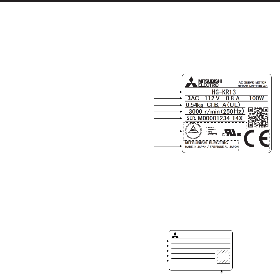
The following shows an example of rating plate for explanation of each item.
(1) HG-MR/HG-KR/HG-SR/HG-JR/HG-RR/HG-UR series servo motor
(Note 2)
Country of origin
Model
Input power and rated output
Mass and insulation class
Rated speed
Serial number (Note 1)
Note 1. Production year and month of the servo motor are indicated in a serial number on
the rating plate.
The year and month are indicated by the last two digits of the year and one digit
of the month [1 to 9, X(10), Y(11), and Z(12)].
For January 2012, the Serial No. is like, "SER. _ _ _ _ _ _ _ _ _ 121".
2. Products approved by Certification Bodies are marked. The marks depends on
the Certification Bodies.
(2) HG-AK series servo motor
Rated output, IP rating
Input power, Mass
Rated speed
Serial number (Note)
Model, Insulation class
AC SERVO MOTORMITSUBISHI
HG-AK0336
INPUT 3AC 13V 2.2A 0.16kg
CI.B
OUTPUT 30W IP55
3000 r/min (200Hz)
SER. J12345678 125
MADE IN JAPANMITSUBISHI ELECTRIC
QR
code
Country of origin
Note. Production year and month of the servo motor are indicated in a serial number on the
rating plate.
The year and month of manufacture are indicated by the last two digits of the year
and one digit of the month [1 to 9, X (10), Y (11), and Z (12)].
For June 2012, the Serial No. is like, "SER. _ _ _ _ _ _ _ _ _ 126".
1. INTRODUCTION
1 - 2
1.2 Parts identification
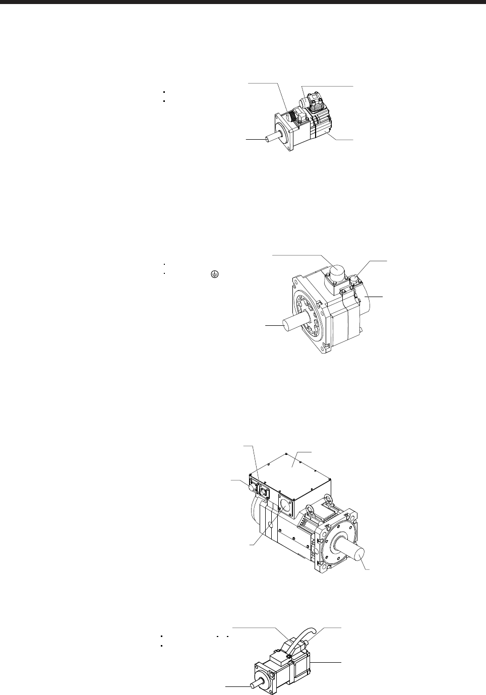
(1) HG-MR series/HG-KR series servo motor
Power cable (Note 1, 2)
Power lead (U/V/W)
Grounding lead
Servo motor shaft
Encoder cable (Note 1)
Encoder
Note 1. The encoder cable and power supply cable are options.
2.
A
n electromagnetic brake cable is separately required for the servo motor with an
electromagnetic brake.
(2) HG-SR series/HG-JR53(4) to HG-JR903(4)/HG-JR701M(4) to HG-JR15K1M(4)/HG-JR601(4) to HG-
JR12K1(4)/HG-RR series/HG-UR series servo motor
Servo motor shaft
Encoder connector
Encoder
Power supply connector (Note
)
Power supply (U/V/W)
Grounding ( )
Note. The servo motor with an electromagnetic brake has the electromagnetic brake
connector separately.
(3) HG-JR22K1M(4) to HG-JR37K1M(4)/HG-JR45K1M4/HG-JR55K1M4/HG-JR15K1(4) to HG-JR37K1(4)
servo motor
Encoder connector
Terminal box
Servo motor shaft
Power lead hole
Cooling fan connecto
r
(4) HG-AK series servo motor
Power cable (Note)
Power lead (U V W)
Earth lead
Encoder cable
Encoder
Servo motor shaft
Note. The servo motor with an electromagnetic brake has electromagnetic brake lead.
1. INTRODUCTION
1 - 3
1.3 Electromagnetic brake
CAUTION
The electromagnetic brake is provided to prevent a drop at a power failure or
servo alarm occurrence during vertical drive or to hold a shaft at a stop. Do not
use it for normal braking (including braking at servo-lock).
The electromagnetic brake has a time lag. Use the electromagnetic brake so that
servo motor control starts after the electromagnetic brake has completely opened.
Be sure to check the time lag of the braking with a real machine.
Configure an electromagnetic brake circuit so that it is activated also by an
external EMG stop switch.
For details of the circuit configuration and timing chart, refer to each servo
amplifier instruction manual.
While the electromagnetic brake is opened, the motor may be raised to high
temperature regardless of driving.
The life will be shorten under sudden acceleration/deceleration conditions.
The servo motor with an electromagnetic brake can be used to prevent a drop in vertical lift applications or to
ensure double safety at an emergency stop, for example. When operating the servo motor, supply power to
the electromagnetic brake to release the brake. Switching power off enables the electromagnetic brake.
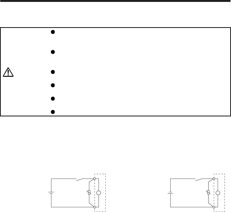
(1) Electromagnetic brake power supply
Prepare the following power supply for use with the electromagnetic brake only. The electromagnetic
brake terminals (B1 and B2) have no polarity.
Electromagnetic brake
Switch
VAR
B1
UB
24 V DC
power supply for
electromagnetic brake
B2
Electromagnetic brake
Switch
VAR
B1
UB
24 V DC
power supply for
electromagnetic brake
B2
or
The surge absorber (VAR) must be installed between B1 and B2. For the selection and example of
surge absorbers, refer to "Electromagnetic brake characteristic" in the chapter of servo motor series.
When you use a diode for a surge absorber, the electromagnetic braking time will be longer.
1. INTRODUCTION
1 - 4
(2) Sound generation
Though the brake lining may rattle during operation, it poses no functional problem.
If braking sounds, it may be improved by setting the machine resonance suppression filter in the servo
amplifier (converter unit) parameters. For details, refer to each servo amplifier instruction manual.
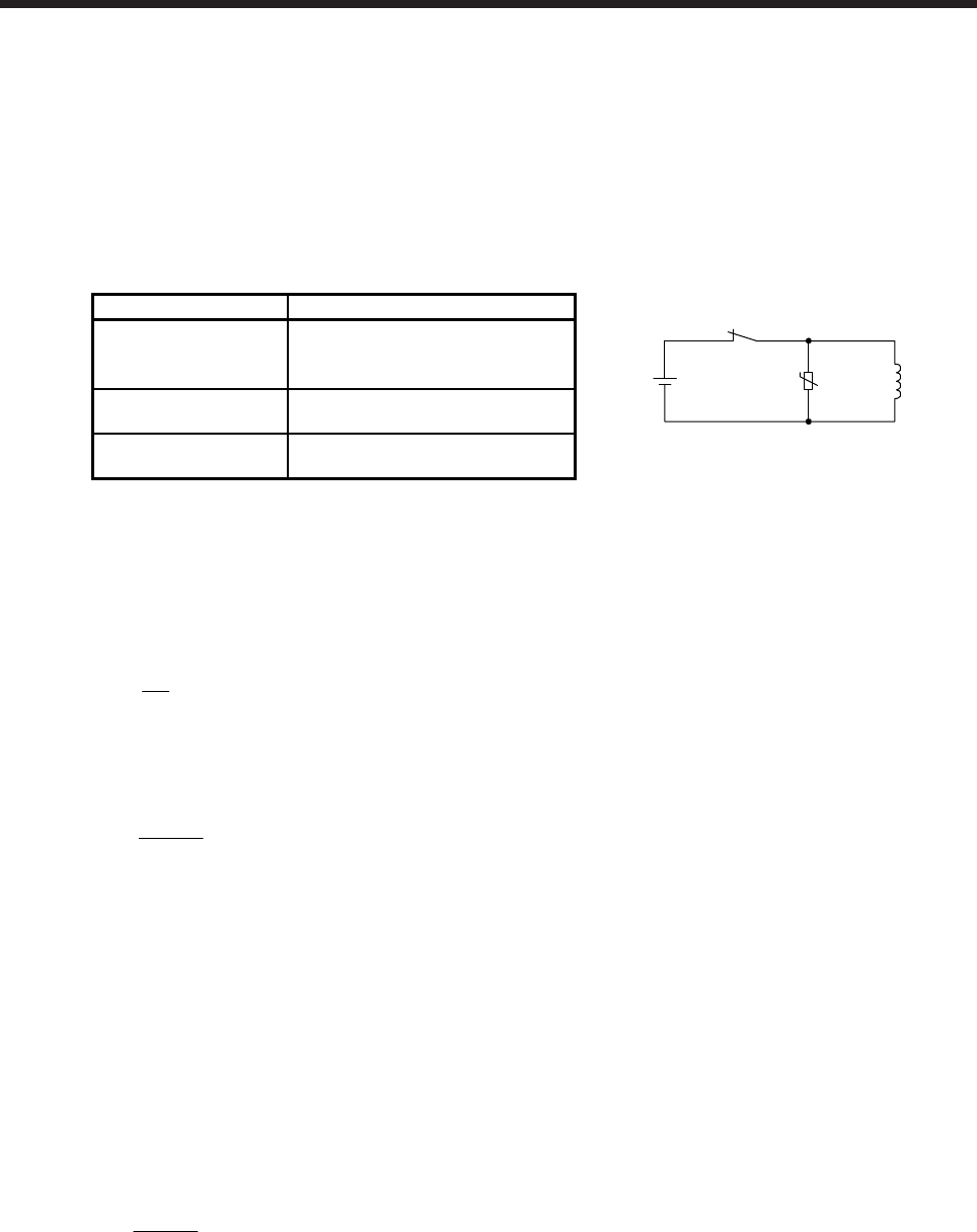
(3) Selection of surge absorbers for electromagnetic brake circuit
The following shows an example how to select a varistor with a surge absorber.
(a) Selection conditions
Item Condition
24 V DC
Relay
Brake coil
UVaristor
Electromagnetic brake
specification
R [Ω]: Resistance
L [H]: Inductance
Vb [V]: Power supply voltage
Desired suppression
voltage
Vs [V] or less
Durable surge
application time
N times
(b) Tentative selection and verification of surge absorber
1) Maximum allowable circuit voltage of varistor
Tentatively select a varistor whose maximum allowable voltage is larger than Vb [V].
2) Brake current (Ib)
Ib = Vb
R [A]
3) Energy (E) generated by brake coil
E = 2
L × lb2 [J]
4) Varistor limit voltage (Vi)
From the energy (E) generated in the brake coil and the varister characteristic diagram, calculate
the varistor limit voltage (Vi) when the brake current (Ib) flows into the tentatively selected varistor
during opening of the circuit.
Vi is favorable when the varistor limit voltage (Vi) [V] is smaller than the desired suppressed
voltage (Vs) [V].
If Vi is not smaller than Vs, reselect a varistor or improve the withstand voltage of devices.
5) Surge current width (τ)
Given that the varistor absorbs all energies, the surge current width (τ) will be as follows.
τ = E
Vi × lb [S]
6) Examining surge life of varister
From the varistor characteristic diagram, the guaranteed current value (Ip) in which the number of
the surge application life is N at the surge current width (τ). Calculate the guaranteed current
value (Ip) ratio to brake current (Ib).
If an enough margin is ensured for Ip/Ib, the number of the surge application life N [time] can be
considered as favorable.
1. INTRODUCTION
1 - 5
(4) Others
A leakage magnetic flux will occur at the shaft end of the servo motor equipped with an electromagnetic
brake. Note that chips, screws, etc. are attracted.
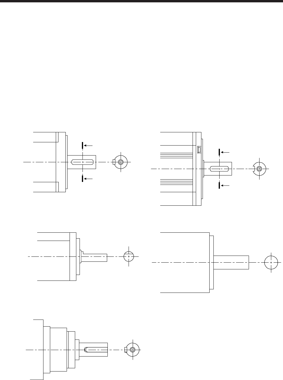
1.4 Servo motor shaft shapes
In addition to the straight shaft, the key shaft and D cut shaft are available.
The key shaft and D cut shaft cannot be used in frequent start/stop applications.
Since we cannot warrant the servo motor against fracture and similar accidents attributable to a loose key,
use a friction coupling, etc. when coupling the shaft with a machine.
The shaft shape of the standard servo motor changes depending on the series and capacity. Refer to the
chapter of the servo motor series.
The key shaft (with single pointed key) applies to only the geared servo motor for high precision application.
Shaft section view AA
A
A
Shaft section view AA
A
A
Key shaft (with 2 round end key) Key shaft (without key)
D cut shaft Straight shaft
Key shaft (with single pointed key)
1. INTRODUCTION
1 - 6
1.5 Servo motor with functional safety
POINT
When you use a servo motor with functional safety, MR-BT6VCASE battery
case cannot be used.
HG-KR, HG-SR, and HG-JR series provide a special specification which expands the safety observation
function with the use of MR-D30 functional safety units and MR-J4-_-RJ servo amplifiers. When using the
servo motor with functional safety, be sure to attach MR-D30 functional safety unit to the servo amplifier.
Other servo motors than HG-KR, HG-SR, and HG-JR series are not compatible with the functional safety.
The servo motors with functional safety have the same specifications and dimensions with the standard
servo motors.
The following is a list of servo amplifiers which are compatible with the servo motors with functional safety.
Refer to section 4.1 of "MR-D30 Instruction Manual" (SH030132) for the available safety observation
functions and achievable safety level.
(1) A combination with 200 V/100 V class servo amplifiers
Servo motor with functional safety Servo amplifier
HG-KR053W0C
HG-KR13W0C
MR-J4-10B-RJ
MR-J4-10A-RJ
MR-J4-10B1-RJ
MR-J4-10A1-RJ
HG-KR23W0C MR-J4-20B-RJ
MR-J4-20A-RJ
MR-J4-20B1-RJ
MR-J4-20A1-RJ
HG-KR43W0C MR-J4-40B-RJ
MR-J4-40A-RJ
MR-J4-40B1-RJ
MR-J4-40A1-RJ
HG-SR51W0C
HG-SR52W0C
MR-J4-60B-RJ
MR-J4-60A-RJ
HG-JR53W0C MR-J4-60B-RJ
MR-J4-60A-RJ
MR-J4-100B-RJ (Note)
MR-J4-100A-RJ (Note)
HG-KR73W0C MR-J4-70B-RJ
MR-J4-70A-RJ
HG-JR73W0C MR-J4-70B-RJ
MR-J4-70A-RJ
MR-J4-200B-RJ (Note)
MR-J4-200A-RJ (Note)
HG-SR81W0C
HG-SR102W0C
MR-J4-100B-RJ
MR-J4-100A-RJ
HG-JR103W0C MR-J4-100B-RJ
MR-J4-100A-RJ
MR-J4-200B-RJ (Note)
MR-J4-200A-RJ (Note)
HG-SR121W0C
HG-SR201W0C
HG-SR152W0C
HG-SR202W0C
MR-J4-200B-RJ
MR-J4-200A-RJ

1. INTRODUCTION
1 - 7
Servo motor with functional safety Servo amplifier
HG-JR153W0C
HG-JR203W0C
MR-J4-200B-RJ
MR-J4-200A-RJ
MR-J4-350B-RJ (Note)
MR-J4-350A-RJ (Note)
HG-SR301W0C
HG-SR352W0C
MR-J4-350B-RJ
MR-J4-350A-RJ
HG-JR353W0C MR-J4-350B-RJ
MR-J4-350A-RJ
MR-J4-500B-RJ (Note)
MR-J4-500A-RJ (Note)
HG-SR421W0C
HG-SR502W0C
MR-J4-500B-RJ
MR-J4-500A-RJ
HG-JR503W0C MR-J4-500B-RJ
MR-J4-500A-RJ
MR-J4-700B-RJ (Note)
MR-J4-700A-RJ (Note)
HG-SR702W0C
HG-JR703W0C
HG-JR701MW0C
MR-J4-700B-RJ
MR-J4-700A-RJ
HG-JR903W0C
HG-JR11K1MW0C
MR-J4-11KB-RJ
MR-J4-11KA-RJ
HG-JR15K1MW0C MR-J4-15KB-RJ
MR-J4-15KA-RJ
HG-JR22K1MW0C MR-J4-22KB-RJ
MR-J4-22KA-RJ
Note. This combination increases the maximum torque from 300% to 400% of the rated
torque.
(2) A combination with 400 V class servo amplifiers
Servo motor with functional safety Servo amplifier
HG-SR524W0C MR-J4-60B4-RJ
MR-J4-60A4-RJ
HG-JR534W0C MR-J4-60B4-RJ
MR-J4-60A4-RJ
MR-J4-100B4-RJ (Note 1)
MR-J4-100A4-RJ (Note 1)
HG-SR1024W0C
HG-JR1034W0C
MR-J4-100B4-RJ
MR-J4-100A4-RJ
HG-JR734W0C
HG-JR1034W0C
MR-J4-100B4-RJ
MR-J4-100A4-RJ
MR-J4-200B4-RJ (Note 1)
MR-J4-200A4-RJ (Note 1)
HG-SR1524W0C
HG-SR2024W0C
MR-J4-200B4-RJ
MR-J4-200A4-RJ
HG-JR1534W0C
HG-JR2034W0C
MR-J4-200B4-RJ
MR-J4-200A4-RJ
MR-J4-350B4-RJ (Note 1)
MR-J4-350A4-RJ (Note 1)
HG-SR3524W0C MR-J4-350B4-RJ
MR-J4-350A4-RJ
HG-JR3534W0C MR-J4-350B4-RJ
MR-J4-350A4-RJ
MR-J4-500B4-RJ (Note 1)
MR-J4-500A4-RJ (Note 1)

1. INTRODUCTION
1 - 8
Servo motor with functional safety Servo amplifier
HG-SR5024W0C MR-J4-500B4-RJ
MR-J4-500A4-RJ
HG-JR5034W0C MR-J4-500B4-RJ
MR-J4-500A4-RJ
MR-J4-700B4-RJ (Note)
MR-J4-700A4-RJ (Note)
HG-SR7024W0C
HG-JR7034W0C
HG-JR701M4W0C
MR-J4-700B4-RJ
MR-J4-700A4-RJ
HG-JR9034W0C
HG-JR11K1M4W0C
MR-J4-11KB4-RJ
MR-J4-11KA4-RJ
HG-JR15K1M4W0C MR-J4-15KB4-RJ
MR-J4-15KA4-RJ
HG-JR22K1M4W0C MR-J4-22KB4-RJ
MR-J4-22KA4-RJ
Note. This combination increases the maximum torque from 300% to 400% of the rated
torque.

2. INSTALLATION
2 - 1
2. INSTALLATION
WARNING
To prevent electric shock, ground each equipment securely.
CAUTION
Stacking in excess of the specified number of product packages is not allowed.
Install the equipment on incombustible material. Installing it directly or close to
combustibles will lead to a fire.
Install the servo motor in a load-bearing place in accordance with the Instruction
Manual.
Do not get on or put heavy load on the equipment. Otherwise, it may cause injury.
Use the equipment within the specified environmental range. For the
environment, refer to the specifications of the servo motor series.
Do not drop or strike the servo motor. Isolate it from all impact loads.
Do not install or operate a faulty servo motor.
Do not carry the servo motor by holding the cables, shaft, encoder, or connector.
Otherwise, it may cause a malfunction or injury.
Use the eyebolts of the servo motor to only transport it. Do not use the eyebolts to
transport the servo motor when it is mounted on a machine.
The geared servo motor must be mounted in the specified direction. Otherwise, it
can leak oil, leading to a fire or malfunction.
Securely fix the servo motor to the machine. If being attached insecurely, the
servo motor may come off during operation, leading to injury.
Be sure to measure the motor vibration level with the servo motor mounted on the
machine when checking the vibration level. A great vibration may cause the early
damage of a bearing, encoder, brake, and reducer. The great vibration may also
cause the poor connector connection or bolt looseness.
For the gain adjustment at the equipment startup, check the torque waveform and
the speed waveform with a measurement device to check that no vibration
occurs. If the vibration occurs due to high gain, the vibration may cause the early
damage of the servo motor.
Never hit the servo motor or shaft, especially when coupling the servo motor to
the machine. Otherwise, the encoder may malfunction.
When coupling a load to the servo motor, do not use a rigid coupling. Doing so
can cause the shaft to break and the bearing to wear out.
Balance the load to the extent possible. Not doing so can cause vibration during
servo motor operation or damage the bearings and encoder.
Take safety measures, e.g. provide covers, to prevent accidental access to the
rotor of the servo motor during operation.
Do not subject the servo motor shaft to more than the permissible load.
Otherwise, the shaft may break, leading to injury.
When the product has been stored for an extended period of time, contact your
local sales office.
When handling the servo motor, be careful about the edged parts such as the
corners of the servo motor.
2. INSTALLATION
2 - 2
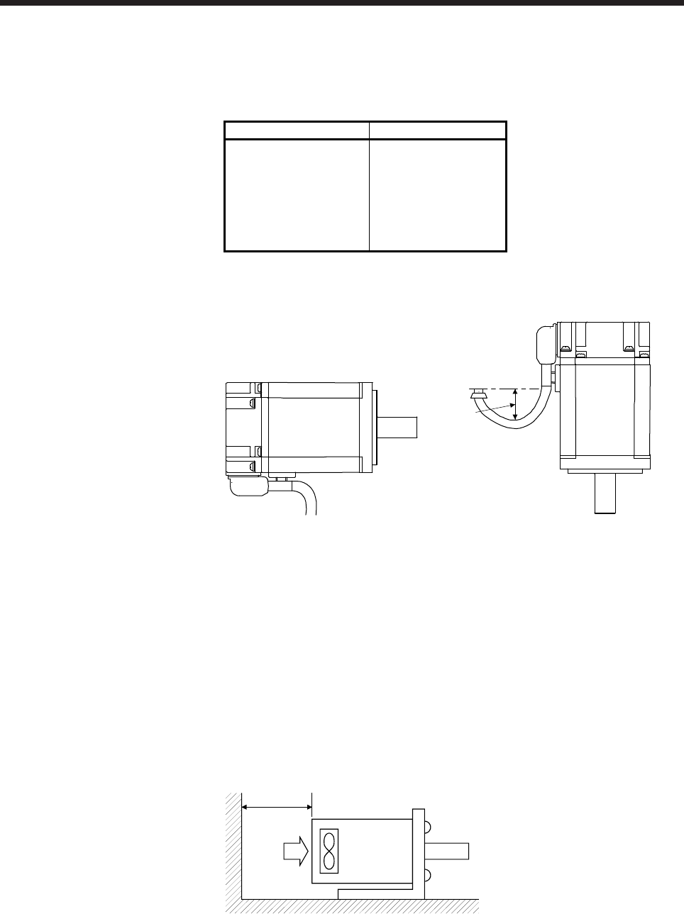
2.1 Mounting direction
(1) Standard servo motor
The following table indicates the mounting direction of the standard servo motor.
Servo motor series Mounting direction
HG-MR
HG-KR
HG-SR
HG-JR
HG-RR
HG-UR
HG-AK
All directions
For mounting in the horizontal direction, it is recommended to set the connector section downward.
When mounting the motor vertically or obliquely, give a little slack for the connection cable.
Little slack
(2) Servo motor with an electromagnetic brake
The servo motor with an electromagnetic brake can also be installed in the same orientation as the
standard servo motor. When the servo motor with an electromagnetic brake is installed with the shaft
end at top, the brake plate may generate sliding sound but it is not a fault.
(3) Geared servo motors
The mounting direction of the geared servo motor differs depending on the reducer type. Be sure to
mount it in the specified direction. Refer to the chapter of the servo motor series for details.
2.2 Cooling fan
For the servo motor with a cooling fan, ensure to put enough space for the distance L between intake port
and wall surface. Refer to the chapter of the servo motor series for the distance L.
Servo motor
Cooling fan
L or more
Intake
2. INSTALLATION
2 - 3
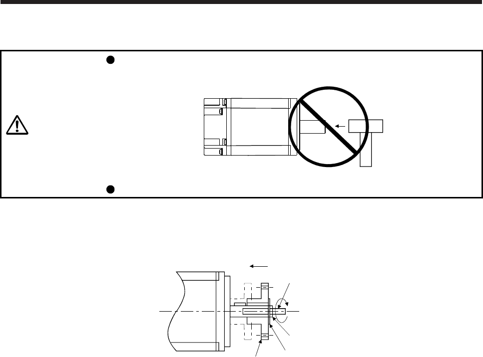
2.3 Load remove precautions
CAUTION
During assembling, the shaft end must not be hammered. Otherwise, the encoder
may malfunction.
Do not process the shaft to avoid damage to the encoder and bearing.
(1) When mounting a pulley to the servo motor with a key shaft, use the screw hole in the shaft end. To fit
the pulley, first insert a double-end stud into the screw hole of the shaft, put a washer against the end
face of the coupling, and insert and tighten a nut to force the pulley in.
Servo motor
Double-end stud
Nut
Washer
Pulley
(2) For the shaft without a key, use a friction coupling or the like.
(3) When removing the pulley, use a pulley remover to protect the shaft from hard load and or impact.
(4) To ensure safety, fit a protective cover or the like on the rotary area, such as the pulley, mounted to the
shaft.
(5) When a threaded shaft end part is needed to mount a pulley on the shaft, please contact your local sales
office.
(6) The direction of the encoder on the servo motor cannot be changed.
(7) When mounting the servo motor, use spring washers, etc. and fully tighten the bolts so that they do not
become loose due to vibration.
2. INSTALLATION
2 - 4
2.4 Permissible load for the shaft
CAUTION Do not use a rigid coupling as it may apply excessive bending load to the shaft of
the servo motor, leading the shaft to break and the bearing to wear out.
For the permissible shaft load specific to the servo motor, refer to the chapter of the servo motor series.
(1) Use a flexible coupling and adjust the misalignment of the shaft to less than the permissible radial load.
(2) When using a pulley, sprocket or timing belt, select a diameter that will fit into the permissible radial load.
(3) Excess of the permissible load can cause the bearing life to reduce and the shaft to break.
(4) The load indicated in this section is static load in a single direction and does not include eccentric load.
Make eccentric load as small as possible. Not doing so can cause the servo motor to be damaged.
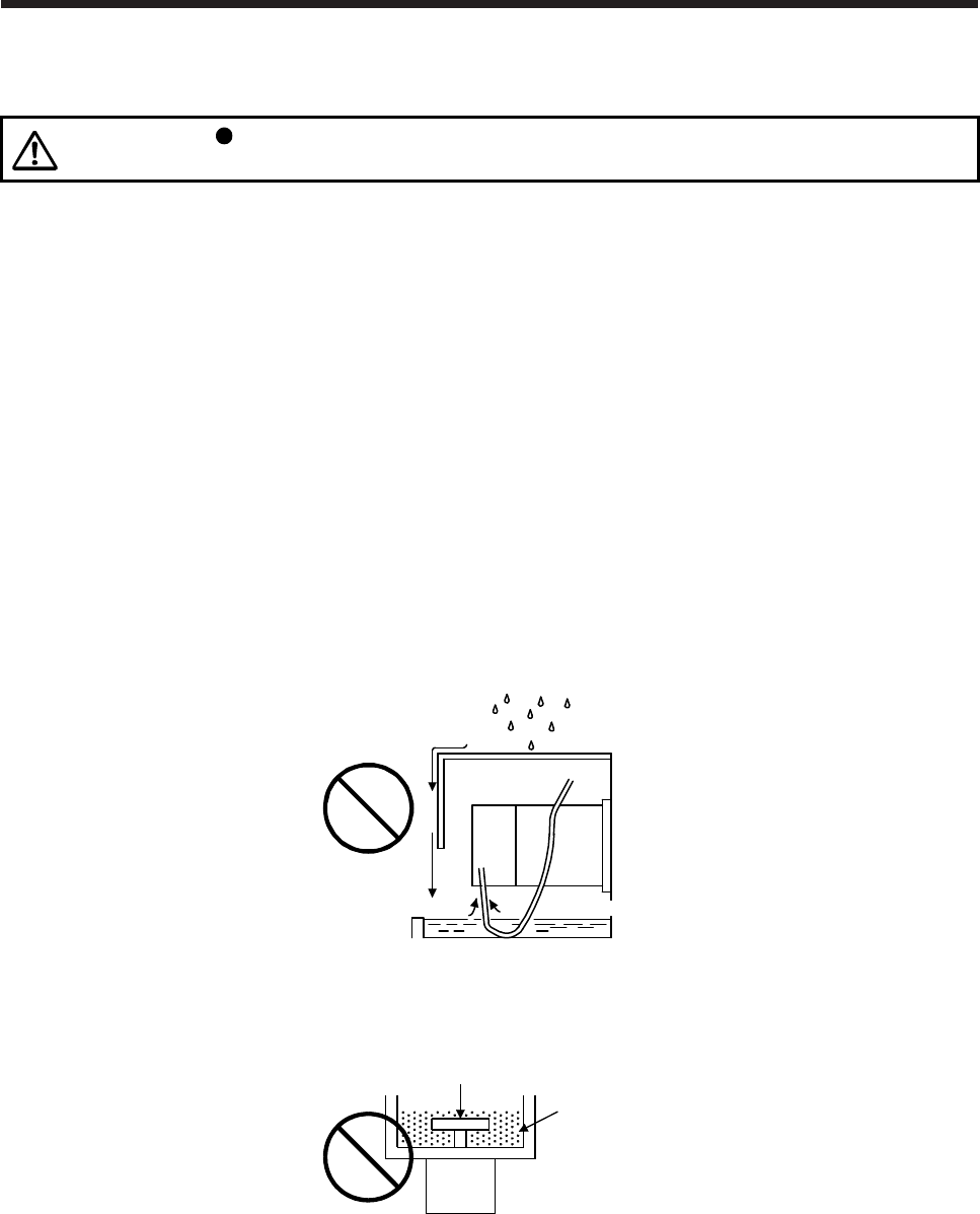
2.5 Protection from oil and water
Provide adequate protection to prevent foreign matter, such as oil from entering the servo motor shaft. When
installing the servo motor, consider the items in this section.
(1) Do not use the servo motor with its cable soaked in oil or water.
Cover
Capillary action
Oil/water pool
Servo
motor
(2) When the servo motor is to be installed with the shaft end at top, provide measures so that it is not
exposed to oil and water entering from the machine side, gear box, etc.
Gear
Lubricating oil
Servo motor
(3) If oil such as cutting oil drops on the servo motor, the sealant, packing, cable and others may be affected
depending on the oil type.
(4) In the environment where the servo motor is exposed to oil mist, oil, water, grease and/or like, a
standard specifications servo motor may not be usable. Please contact your local sales office.
2. INSTALLATION
2 - 5
2.6 Cable
The power supply and encoder cables routed from the servo motor should be fixed to the servo motor to
keep them unmovable. Otherwise, the cable may disconnect. In addition, do not modify the connectors,
terminals and others at the ends of the cables.
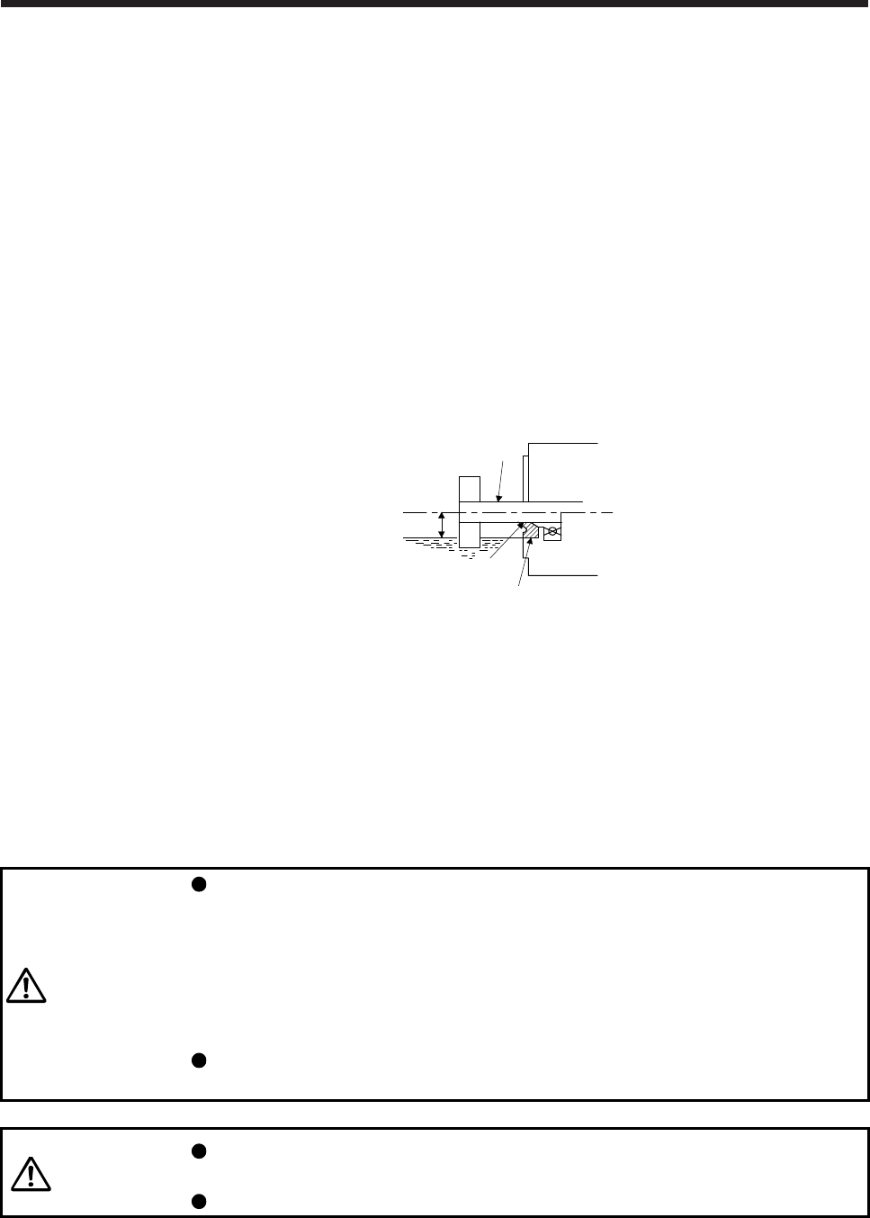
2.7 Servo motor with oil seal
For the servo motor with oil seal, the oil seal prevents the entry of oil into the servo motor. Make sure to
install it according in this section.
The functions have no problem even if the servo motor with oil seal may sound during operation.
(1) Pressure and oil level
Install the servo motor horizontally, and set the oil level in the gear box to be lower than the oil seal lip
always. If the oil level is higher than the oil seal lip, the oil enter the servo motor and may cause a
malfunction. Refer to the chapter of the servo motor series for the oil level.
GearShaft
Servo motor
Oil seal
Height above oil level h
Lip
High pressure against the oil seal causes the abrasion and makes the life be short. Keep constant
internal pressure by equipping a ventilator to the gear box.
(2) Temperature
High temperature against the oil seal lip makes the life be short. Avoid exposing the oil seal lip to high
temperature oil since applicable temperature of the material is up to 100 °C and temperature of the oil
seal lip rises within 10 °C to 15 °C at maximum rotation.
2.8 Inspection items
WARNING
Before starting maintenance and/or inspection, turn off the power and wait for 15
minutes or more (20 minutes or more for converter unit and drive unit) until the
charge lamp turns off. Then, confirm that the voltage between P+ and N- (L+ and
L- for converter unit and drive unit) is safe with a voltage tester and others.
Otherwise, an electric shock may occur. In addition, when confirming whether the
charge lamp is off or not, always confirm it from the front of the servo amplifier
(converter unit).
To avoid an electric shock, only qualified personnel should attempt inspections.
For repair and parts replacement, contact your local sales office.
CAUTION
Do not perform insulation resistance test on the servo motor. Otherwise, it may
cause a malfunction.
Do not disassemble and/or repair the equipment on customer side.
It is recommended that the following points periodically be checked.
(1) Check the bearings, brake section, etc. for unusual noise.
2. INSTALLATION
2 - 6
(2) Check the cables and the like for scratches or cracks. Especially when the cable is movable, perform
periodic inspection according to operating conditions.
(3) Check the servo motor shaft and coupling for misalignment.
(4) Check the power supply connector and encoder connector tightening screws for looseness.
2.9 Parts having service lives
Service lives of the following parts are listed below. However, the service lives vary depending on operation
and environment. If any fault is found in the parts, they must be replaced immediately regardless of their
service lives. For parts replacement, please contact your local sales office.
Part name Life guideline
Bearings 20,000 hours to
30,000 hours
Encoder 20,000 hours to
30,000 hours
Cooling fan 20,000 hours
Oil seal 5000 hours
Reducer 10,000 hours to
20,000 hours
(1) Bearings
When the servo motor is run at rated speed under rated load, bearings should be exchanged in 20,000
to 30,000 hours as a guideline. This differs on the operating conditions. The bearings must also be
changed if unusual noise or vibration is found during inspection.
(2) Oil seal (including oil seal used on the reducer)
Oil seals must be changed in 5,000 hours of operation at rated speed as a guideline. They must also be
changed if oil leakage, etc. is found during inspection.
The functions have no problem even if an oil seal may sound during operation.
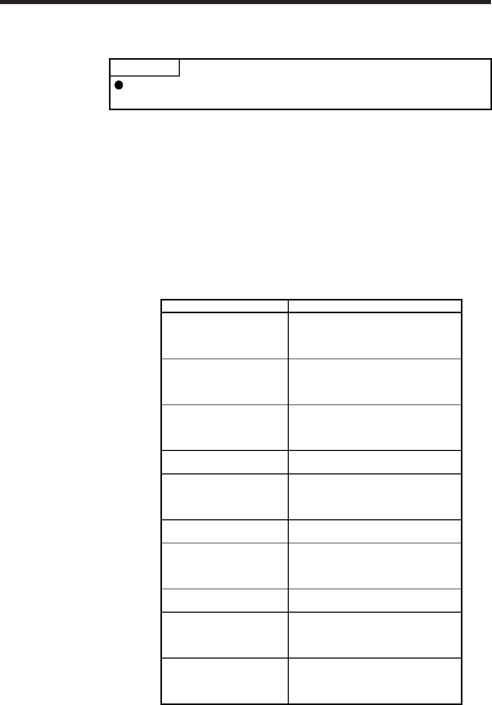
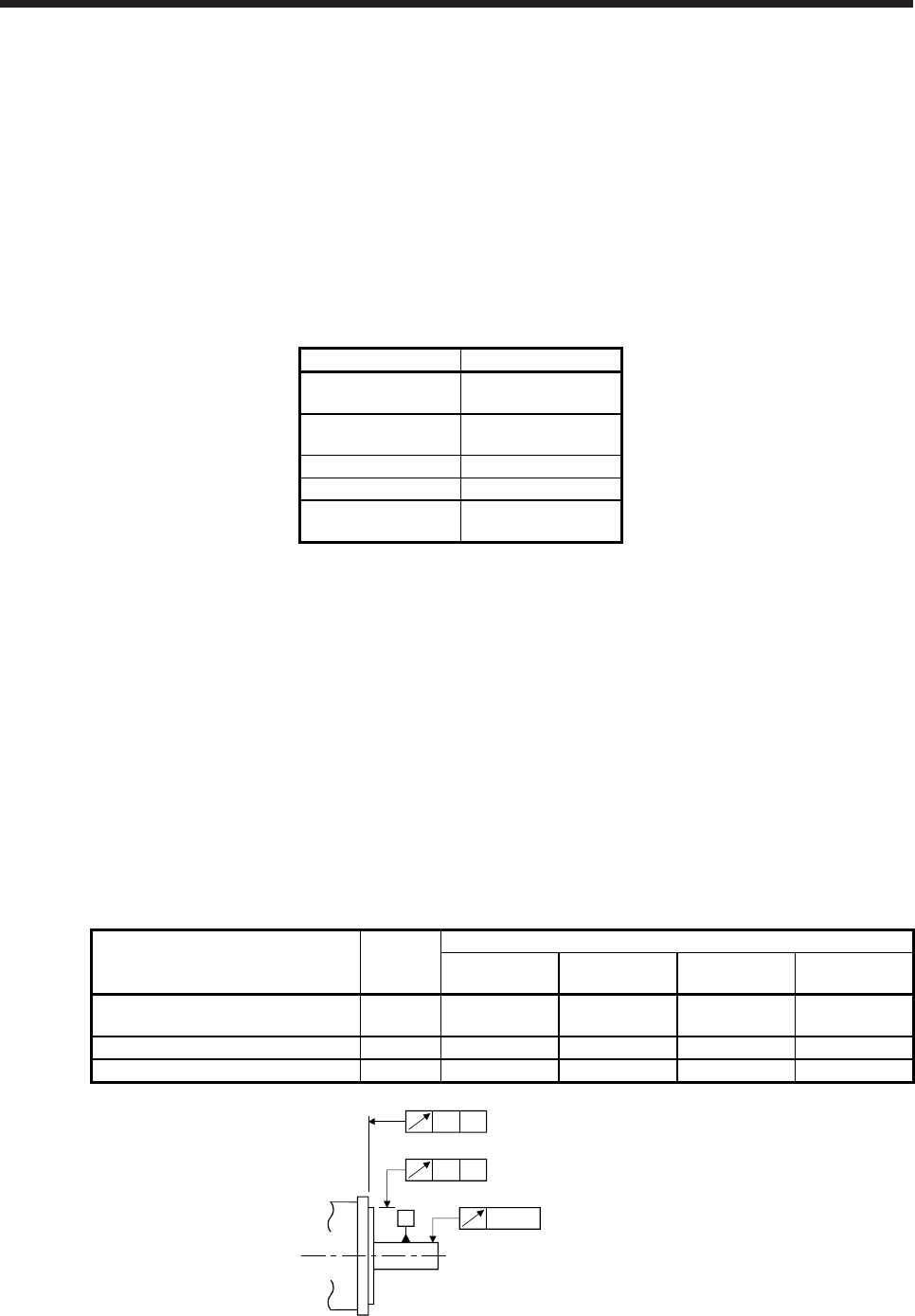
2.10 Machine accuracies
The following table indicates the machine accuracies of the servo motor around the output shaft and
mounting. (except the optional products)
Accuracy [mm] Measuring
position
Flange size
100 × 100 or
less 130 × 130 176 × 176 to
250 × 250
280 × 280 or
more
Runout of flange surface to output
shaft a) 0.05 0.06 0.08 0.08
Runout of fitting OD of flange surface b) 0.04 0.04 0.06 0.08
Runout of output shaft end c) 0.02 0.02 0.03 0.03
b)
c)
a) A
A
A
3. CONNECTORS USED FOR SERVO MOTOR WIRING
3 - 1
3. CONNECTORS USED FOR SERVO MOTOR WIRING
POINT
The IP rating indicated is the connector's protection against ingress of dust and
water when the connector is connected to a servo motor. If the IP rating of the
connector and servo motor vary, the overall IP rating depends on the lowest IP
rating of all components.
3.1 Selection of connectors
Use the connector configuration products given in the table as the connectors for connection with the servo
motor. Refer to section 3.2 to 3.4 for the compatible connector configuration products.
(1) HG-MR series and HG-KR series
Encoder connecto
r
Electromagnetic brake connector
Power supply connector
Servo motor
Wiring connector
For encoder For power supply For electromagnetic
brake
HG-MR_
HG-KR_
Connector
configuration A
Connector
configuration B
Connector
configuration C
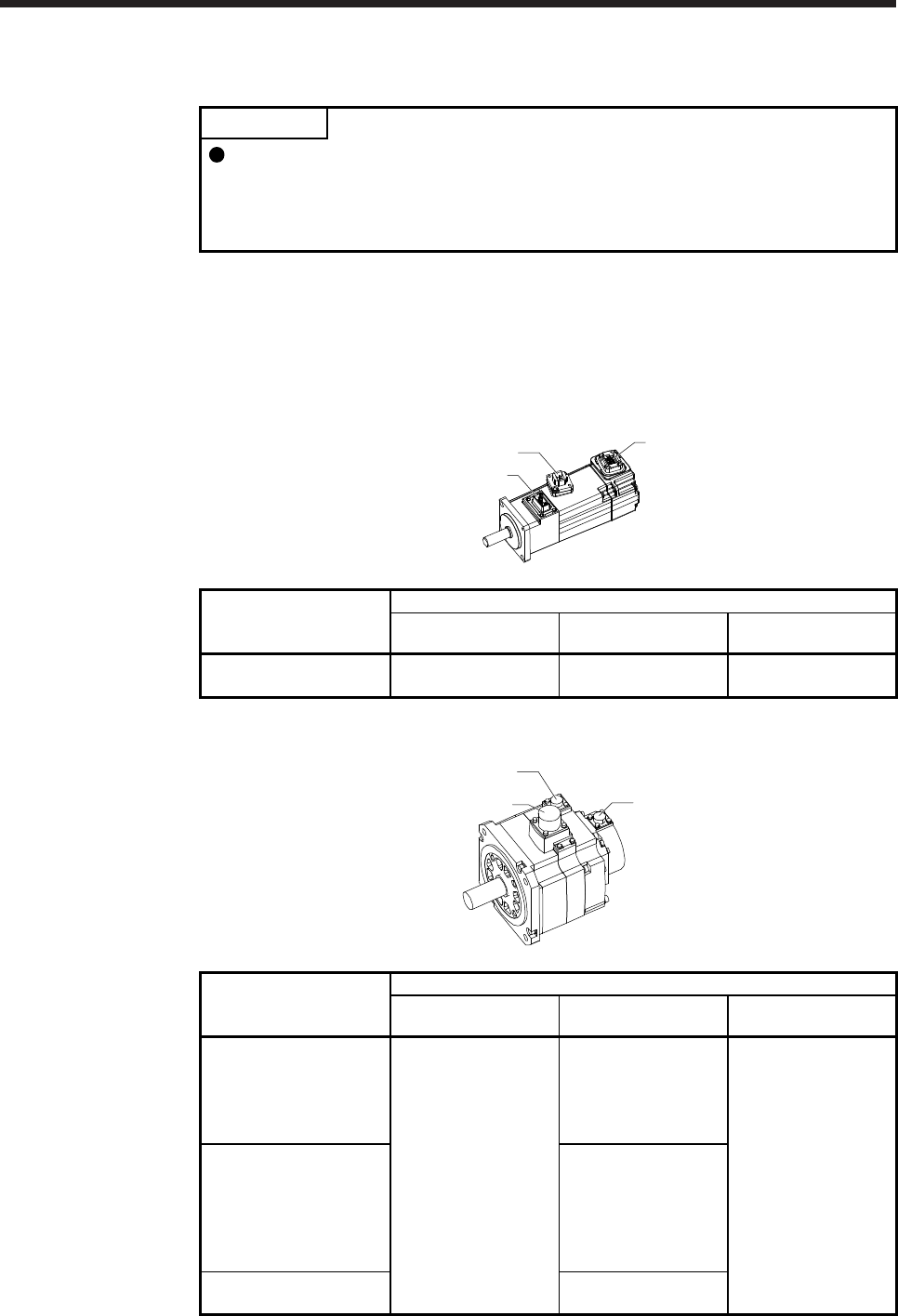
(2) HG-SR series
Encoder connector
Power supply connector
Electromagnetic brake connecto
r
Servo motor
Wiring connector
For encoder For power supply For electromagnetic
brake
HG-SR51
HG-SR81
HG-SR52(4)
HG-SR102(4)
HG-SR152(4)
Connector
configuration D
Connector
configuration E
Connector
configuration F
HG-SR121
HG-SR201
HG-SR301
HG-SR202(4)
HG-SR352(4)
HG-SR502(4)
Connector
configuration G
HG-SR421
HG-SR702(4)
Connector
configuration H
3. CONNECTORS USED FOR SERVO MOTOR WIRING
3 - 2
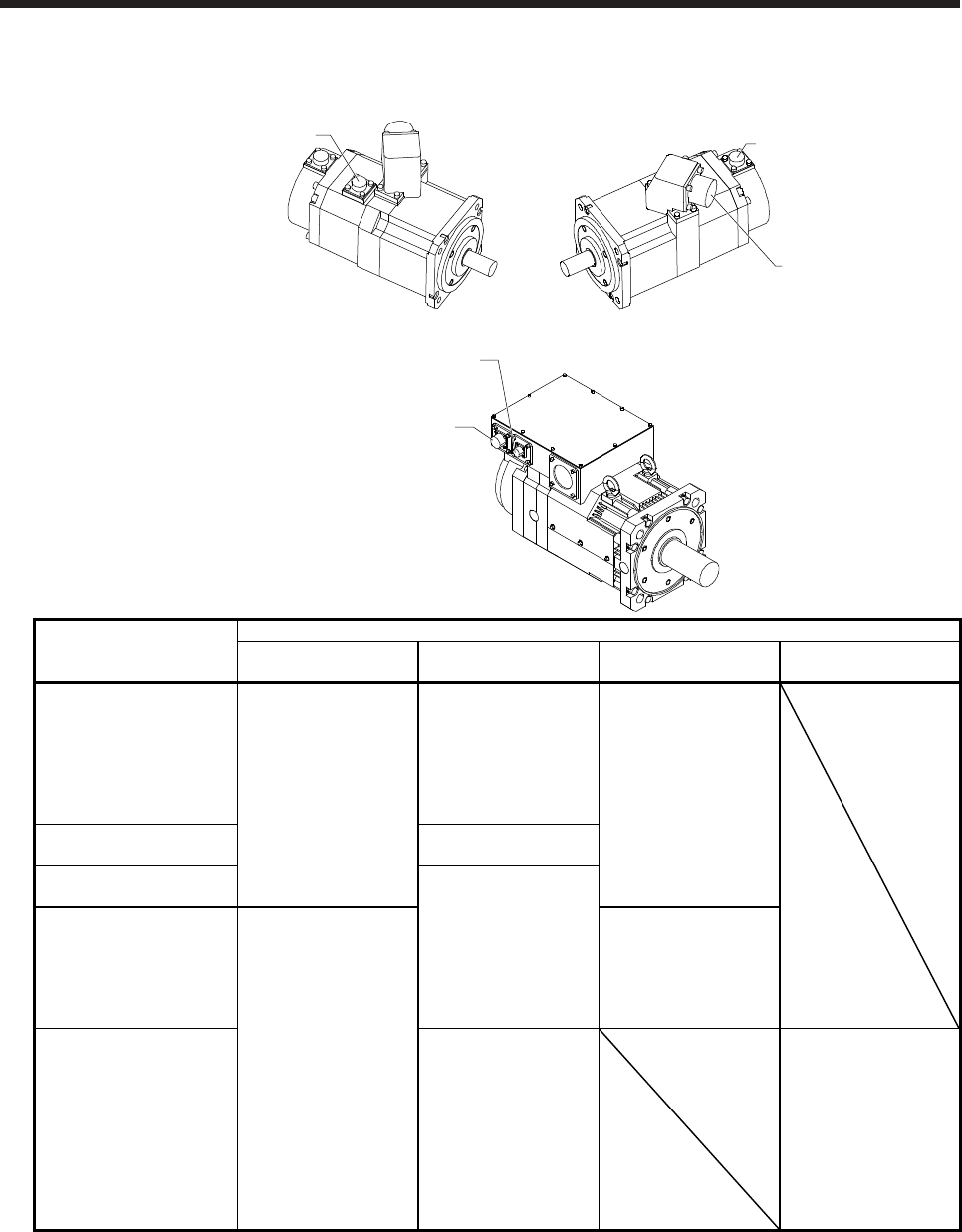
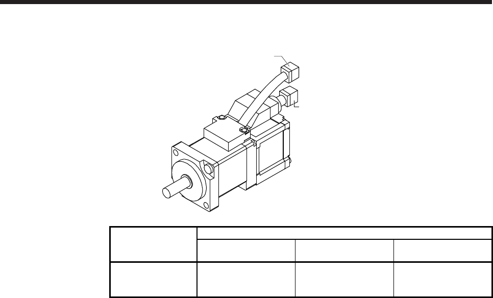
(3) HG-JR series
HG-JR53(4) to HG-JR903(4)/HG-JR701M(4) to HG-JR15K1M(4)/HG-JR601(4) to HG-JR12K1(4)
Electromagnetic brake connector Encoder connector
Power supply connector
HG-JR22K1M(4) to HG-JR37K1M(4)/HG-JR45K1M4/HG-JR55K1M4/HG-JR15K1(4) to HG-JR37K1(4)
Encoder connector
Cooling fan connecto
r
Servo motor
Wiring connector
For encoder For power supply For electromagnetic
brake For cooling fan
HG-JR53(4)
HG-JR73(4)
HG-JR103(4)
HG-JR153(4)
HG-JR203(4)
HG-JR3534
HG-JR5034
Connector
configuration D
Connector
configuration E
Connector
configuration F
HG-JR353
HG-JR503
Connector
configuration G
HG-JR703(4)
HG-JR903(4)
Connector
configuration H
HG-JR701M(4)
HG-JR11K1M(4)
HG-JR15K1M(4)
HG-JR601(4)
HG-JR801(4)
HG-JR12K1(4)
Connector
configuration K
Connector
configuration J
HG-JR22K1M(4)
HG-JR30K1M(4)
HG-JR37K1M(4)
HG-JR45K1M4
HG-JR55K1M4
HG-JR15K1(4)
HG-JR20K1(4)
HG-JR25K1(4)
HG-JR30K1(4)
HG-JR37K1(4)
None (terminal box) Connector
configuration L
3. CONNECTORS USED FOR SERVO MOTOR WIRING
3 - 3
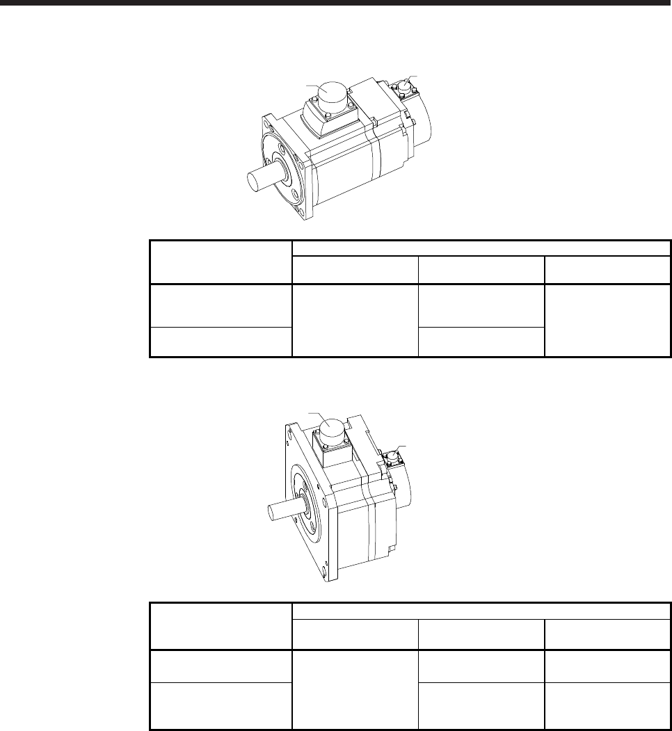
(4) HG-RR series
Power connecto
r
Encoder connector
Servo motor
Wiring connector
For encoder For power supply For electromagnetic
brake
HG-RR103
HG-RR153
HG-RR203 Connector
configuration D
Connector
configuration N Sharing for power
supply
HG-RR353
HG-RR503
Connector
configuration M
(5) HG-UR series
Power connecto
r
Encoder connector
Servo motor
Wiring connector
For encoder For power supply For electromagnetic
brake
HG-UR72
HG-UR152 Connector
configuration D
Connector
configuration N
Sharing for power
supply (Note)
HG-UR202
HG-UR352
HG-UR502
Connector
configuration M
Connector
configuration J
Note. Electromagnetic brake connector is not required since the power supply connector has a pin
assigned for electromagnetic brake.
3. CONNECTORS USED FOR SERVO MOTOR WIRING
3 - 4
(6) HG-AK series
Power connecto
r
Encoder connector
Servo motor
Wiring connector
For encoder For power supply For electromagnetic
brake
HG-AK0136
HG-AK0236
HG-AK0336
Connector configuration
P
Connector configuration
Q
Sharing for power supply
(Note)
Note.
A
n electromagnetic brake connector is not required since the power connector has a pin assigned
for electromagnetic brake.
3. CONNECTORS USED FOR SERVO MOTOR WIRING
3 - 5
3.2 Wiring connectors (connector configurations A/B/C)
Connector
configuration Feature Connector Crimping tool
Servo motor encoder
connector (Note)
A
(for encoder) IP65 Connector: 2174053-1
(TE Connectivity)
For ground clip: 1596970-1
For REC. contact: 1596847-1
(TE Connectivity)
1674339-1
(TE Connectivity)
Note. The other side connector
Connector
configuration Feature Connector Crimping tool
Servo motor power supply
connector (Note)
B
(for power supply) IP65
Connector: KN4FT04SJ1-R
HOOD/SOCKET INSULATOR/
BUSHING/GROUND NUT
Contact: ST-TMH-S-C1B-100 (A534G)
(JAE)
CT170-14-TMH5B
(JAE)
JN4AT04NJ1
(JAE)
Note. The other side connector
Connector
configuration Feature Connector Crimping tool
Servo motor
electromagnetic brake
connector (Note)
C
(for
electromagnetic
brake)
IP65
Connector: JN4FT02SJ1-R
HOOD/SOCKET INSULATOR/
BUSHING/GROUND NUT
Contact: ST-TMH-S-C1B-100 (A534G)
(JAE)
CT170-14-TMH5B
(JAE)
JN4AT02PJ1
(JAE)
Note. The other side connector
3. CONNECTORS USED FOR SERVO MOTOR WIRING
3 - 6
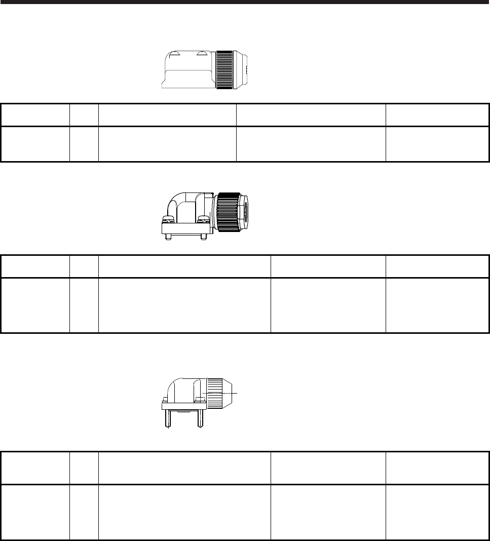
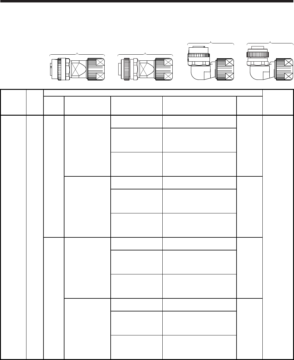
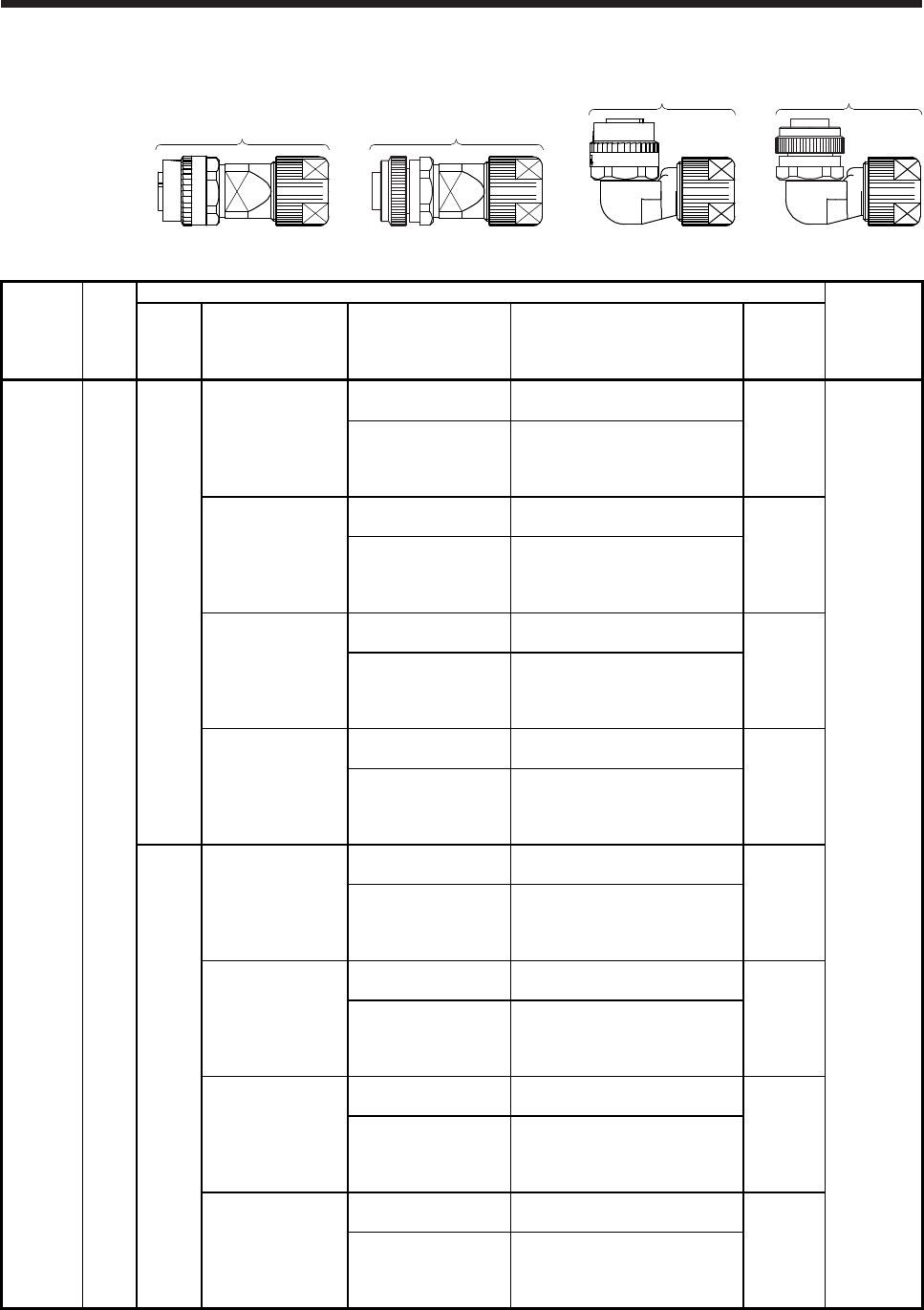
3.3 Wiring connectors (connector configurations D/E/F/G/H)
Angle plug
(screw type)
Angle plug
(one-touch connection type)
Straight plug
(screw type)
Straight plug
(one-touch connection type)
Connector
configuration Feature
Plug (DDK) Servo motor
encoder
connector
(Note)
Type Plug Socket contact Contact shape
Cable OD
[mm]
(reference)
D
(for encoder) IP67
Straight
CMV1-SP10S-M1
(one-touch connection
type)
CMV1S-SP10S-M1
(screw type)
CMV1-#22ASC-S1-100 Soldering type
Applicable wire size: AWG 20 or less
5.5 to 7.5
CMV1-R10P
CMV1-#22ASC-C1-100
Crimping type
Applicable wire size: AWG 24 to 20
The crimping tool (357J-53162T) is
required.
CMV1-#22ASC-C2-100
Crimping type
Applicable wire size: AWG 28 to 24
The crimping tool (357J-53163T) is
required.
CMV1-SP10S-M2
(one-touch connection
type)
CMV1S-SP10S-M2
(screw type)
CMV1-#22ASC-S1-100 Soldering type
Applicable wire size: AWG 20 or less
7.0 to 9.0
CMV1-#22ASC-C1-100
Crimping type
Applicable wire size: AWG 24 to 20
The crimping tool (357J-53162T) is
required.
CMV1-#22ASC-C2-100
Crimping type
Applicable wire size: AWG 28 to 24
The crimping tool (357J-53163T) is
required.
Angle
CMV1-AP10S-M1
(one-touch connection
type)
CMV1S-AP10S-M1
(screw type)
CMV1-#22ASC-S1-100 Soldering type
Applicable wire size: AWG 20 or less
5.5 to 7.5
CMV1-#22ASC-C1-100
Crimping type
Applicable wire size: AWG 24 to 20
The crimping tool (357J-53162T) is
required.
CMV1-#22ASC-C2-100
Crimping type
Applicable wire size: AWG 28 to 24
The crimping tool (357J-53163T) is
required.
CMV1-AP10S-M2
(one-touch connection
type)
CMV1S-AP10S-M2
(screw type)
CMV1-#22ASC-S1-100 Soldering type
Applicable wire size: AWG 20 or less
7.0 to 9.0
CMV1-#22ASC-C1-100
Crimping type
Applicable wire size: AWG 24 to 20
The crimping tool (357J-53162T) is
required.
CMV1-#22ASC-C2-100
Crimping type
Applicable wire size: AWG 28 to 24
The crimping tool (357J-53163T) is
required.
Note. The other side connector
3. CONNECTORS USED FOR SERVO MOTOR WIRING
3 - 7
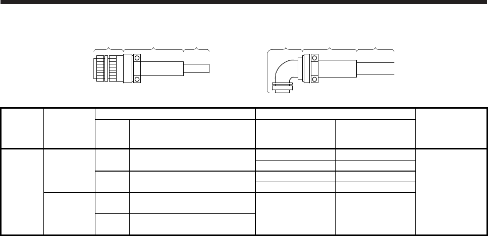
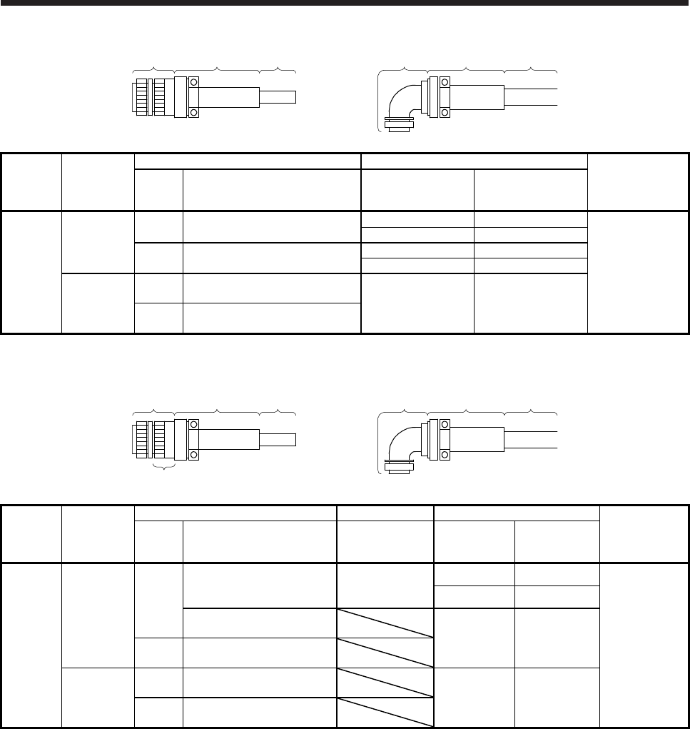
Plug Cable clamp Cable Plug Cable clamp Cable
Connector
configuration Feature
Plug (DDK) Cable clamp (DDK) Servo motor
power supply
connector
(Note 2)
Type Model Cabel OD
[mm] (reference) Model
E
(for power
supply)
IP67
EN compliant
Straight CE05-6A18-10SD-D-BSS
Applicable wire size: AWG 14 to 12
8.5 to 11 CE3057-10A-2-D
MS3102A18-10P
10.5 to 14.1 CE3057-10A-1-D
Angle CE05-8A18-10SD-D-BAS
Applicable wire size: AWG 14 to 12
8.5 to 11 CE3057-10A-2-D
10.5 to 14.1 CE3057-10A-1-D
(Note 1)
General
environment
Straight D/MS3106B18-10S
Applicable wire size: AWG 14 to 12 14.3 or less
(bushing ID) D/MS3057-10A
Angle D/MS3108B18-10S
Applicable wire size: AWG 14 to 12
Note 1. Not comply with EN.
2. The other side connector
3. CONNECTORS USED FOR SERVO MOTOR WIRING
3 - 8
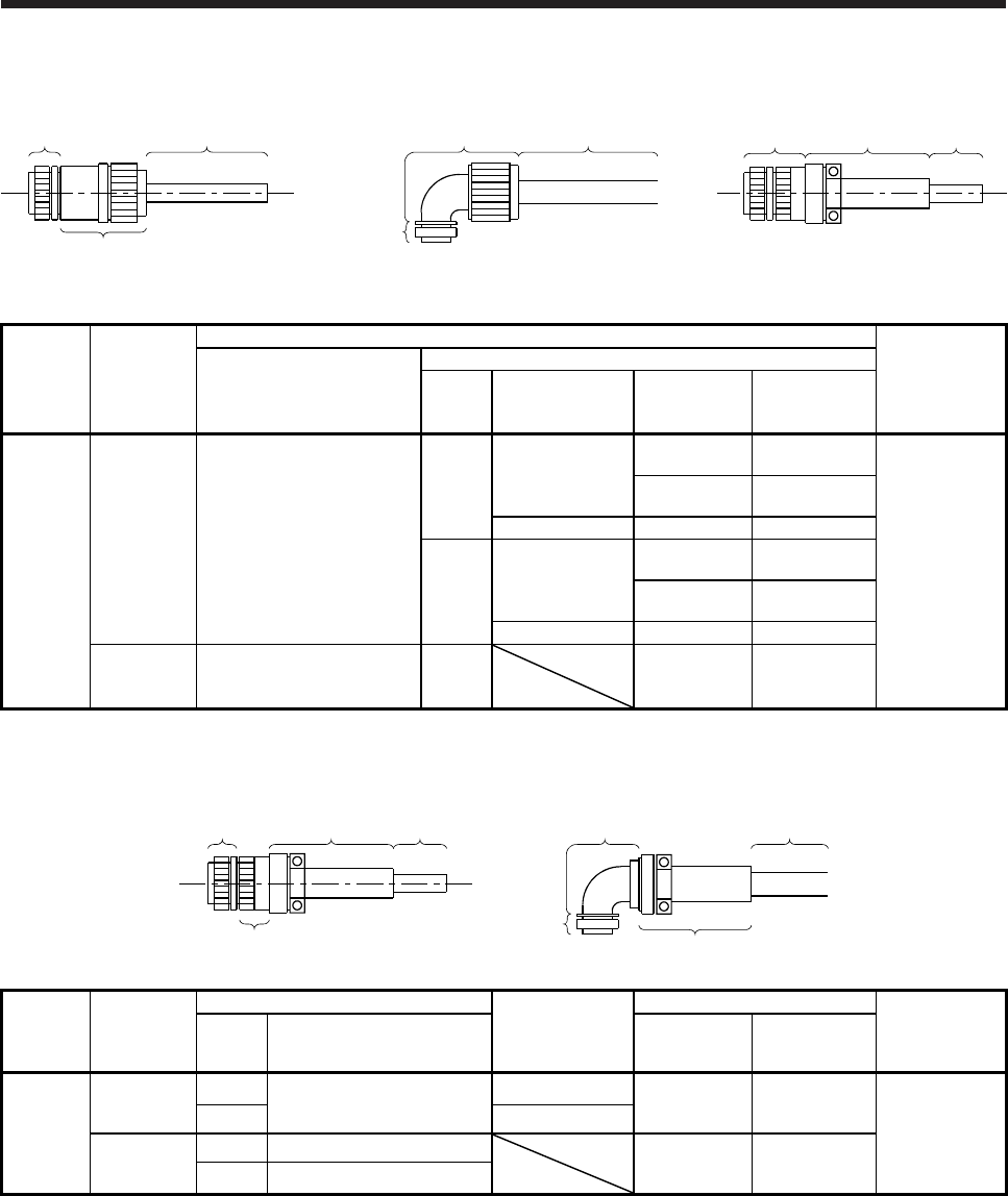
Angle plug
(screw type)
Angle plug
(one-touch connection type)
Straight plug
(screw type)
Straight plug
(one-touch connection type)
Connector
configuration Feature
Plug (DDK) Servo motor
electro-
magnetic brake
connector
(Note)
Type Plug Socket contact Contact shape
Cable OD
[mm]
(reference)
F
(for electro-
magnetic
brake)
IP67
Straight
CMV1-SP2S-S
(one-touch connection
type)
CMV1S-SP2S-S
(screw type)
CMV1-#22BSC-S2-100 Soldering type
Applicable wire size: AWG 16 or less
4.0 to 6.0
CMV1-R2P
CMV1-#22BSC-C3-100
Crimping type
Applicable wire size: AWG 20 to 16
The crimping tool (357J-53164T) is
required.
CMV1-SP2S-M1
(one-touch connection
type)
CMV1S-SP2S-M1
(screw type)
CMV1-#22BSC-S2-100 Soldering type
Applicable wire size: AWG 16 or less
5.5 to 7.5
CMV1-#22BSC-C3-100
Crimping type
Applicable wire size: AWG 20 to 16
The crimping tool (357J-53164T) is
required.
CMV1-SP2S-M2
(one-touch connection
type)
CMV1S-SP2S-M2
(screw type)
CMV1-#22BSC-S2-100 Soldering type
Applicable wire size: AWG 16 or less
7.0 to 9.0
CMV1-#22BSC-C3-100
Crimping type
Applicable wire size: AWG 20 to 16
The crimping tool (357J-53164T) is
required.
CMV1-SP2S-L
(one-touch connection
type)
CMV1S-SP2S-L
(screw type)
CMV1-#22BSC-S2-100 Soldering type
Applicable wire size: AWG 16 or less
9.0 to 11.6
CMV1-#22BSC-C3-100
Crimping type
Applicable wire size: AWG 20 to 16
The crimping tool (357J-53164T) is
required.
Angle
CMV1-AP2S-S
(one-touch connection
type)
CMV1S-AP2S-S
(screw type)
CMV1-#22BSC-S2-100 Soldering type
Applicable wire size: AWG 16 or less
4.0 to 6.0
CMV1-#22BSC-C3-100
Crimping type
Applicable wire size: AWG 20 to 16
The crimping tool (357J-53164T) is
required.
CMV1-AP2S-M1
(one-touch connection
type)
CMV1S-AP2S-M1
(screw type)
CMV1-#22BSC-S2-100 Soldering type
Applicable wire size: AWG 16 or less
5.5 to 7.5
CMV1-#22BSC-C3-100
Crimping type
Applicable wire size: AWG 20 to 16
The crimping tool (357J-53164T) is
required.
CMV1-AP2S-M2
(one-touch connection
type)
CMV1S-AP2S-M2
(screw type)
CMV1-#22BSC-S2-100 Soldering type
Applicable wire size: AWG 16 or less
7.0 to 9.0
CMV1-#22BSC-C3-100
Crimping type
Applicable wire size: AWG 20 to 16
The crimping tool (357J-53164T) is
required.
CMV1-AP2S-L
(one-touch connection
type)
CMV1S-AP2S-L
(screw type)
CMV1-#22BSC-S2-100 Soldering type
Applicable wire size: AWG 16 or less
9.0 to 11.6
CMV1-#22BSC-C3-100
Crimping type
Applicable wire size: AWG 20 to 16
The crimping tool (357J-53164T) is
required.
Note. The other side connector
3. CONNECTORS USED FOR SERVO MOTOR WIRING
3 - 9
Plug Cable clamp Cable Plug Cable clamp Cable
Connector
configuration Feature
Plug (DDK) Cable clamp (DDK) Servo motor
power supply
connector
(Note 2)
Type Model Cabel OD
[mm] (reference) Model
G
(for power
supply)
IP67
EN compliant
Straight CE05-6A22-22SD-D-BSS
Applicable wire size: AWG 10 to 8
9.5 to 13 CE3057-12A-2-D
MS3102A22-22P
12.5 to 16 CE3057-12A-1-D
Angle CE05-8A22-22SD-D-BAS
Applicable wire size: AWG 10 to 8
9.5 to 13 CE3057-12A-2-D
12.5 to 16 CE3057-12A-1-D
(Note 1)
General
environment
Straight D/MS3106B22-22S
Applicable wire size: AWG 10 to 8 15.9 or less
(bushing ID) D/MS3057-12A
Angle D/MS3108B22-22S
Applicable wire size: AWG 10 to 8
Note 1. Not comply with EN.
2. The other side connector
Plug Cable clamp Cable Plug Cable clamp Cable
Backshell
Connector
configuration Feature
Plug (DDK) Backshell Cable clamp (DDK) Servo motor
power supply
connector
(Note 2)
Type Model Model
Cabel OD
[mm] (reference) Model
H
(for power
supply)
IP67
EN compliant
Straight
(Note 3)
CE05-6A32-17SD-D
Applicable wire size: AWG 4
CE05-32BS-S-D-OB
30 to 32.5 CE3057-24A-1-D
MS3102A32-17P
27 to 29.6 CE3057-24A-2-D
CE05-6A32-17SD-D-BSS
Applicable wire size: AWG 6 to 4
22 to 23.8 CE3057-20A-1-D
Angle CE05-8A32-17SD-D-BAS
Applicable wire size: AWG 6 to 4
(Note 1)
General
environment
Straight D/MS3106B32-17S
Applicable wire size: AWG 6 to 4
23.8 or less
(bushing ID) D/MS3057-20A
Angle D/MS3108B32-17S
Applicable wire size: AWG 6 to 4
Note 1. Not comply with EN.
2. The other side connector
3. This connector is used only when the outer diameter of the cable used for HG-JR11K1M(4) and HG-JR15K1M(4) exceeds
23.8 mm.
3. CONNECTORS USED FOR SERVO MOTOR WIRING
3 - 10
3.4 Wiring connectors (connector configurations J/K/L/M/N/P/Q)
IP67 compatible IP67 compatible General environmental
Plug Cable
Connector for cable Plug
Connector for cable Cable Plug Cable
clamp Cable
Connector
configuration Feature
Cable-side connector Servo motor
electromagnetic
brake
connector
(Note 2)
Plug (DDK)
Connector for cable
Type Manufacturer
Cable OD
[mm]
(reference)
Model
J
(for
electro-
magnetic
brake)
IP67
EN
UL/CSA
compliant
D/MS3106A10SL-4S
(D190)
Applicable wire size:
AWG 22 to 16
Straight Nippon Flex
4 to 8 ACS-08RL-
MS10F
MS3102A10SL-
4P
8 to 12 ACS-12RL-
MS10F
Daiwa Dengyo 5 to 8.3 YSO10-5 to 8
Angle Nippon Flex
4 to 8 ACA-08RL-
MS10F
8 to 12 ACA-12RL-
MS10F
Daiwa Dengyo 5 to 8.3 YLO10-5 to 8
(Note1)
General
environment
D/MS3106A10SL-4S
Applicable wire size:
AWG 22 to 16
Straight 5.6 or less
(bushing ID) D/MS3057-4A
Note 1. Not comply with EN.
2. The connector to be mated.
Plug Cable
clamp Cable
Backshell
Backshell Cable
Cable clamp
Plug
Connector
configuration Feature
Plug (DDK)
Backshell
(DDK)
Cable clamp (DDK) Servo motor
encoder
connector
(Note 2)
Type Model Cable OD
[mm] Model
K
(for
encoder)
IP67
EN
compliant
Straight D/MS3106A20-29S (D190) CE02-20BS-S-D 6.8 to 10 CE3057-12A-3-D
D/MS3102A20-
29P
Angle CE-20BA-S-D
(Note 1)
General
environment
Straight D/MS3106B20-29S 15.9 or less
(bushing ID) D/MS3057-12A
Angle D/MS3108B20-29S
Note 1. Not comply with EN.
2. The connector to be mated.
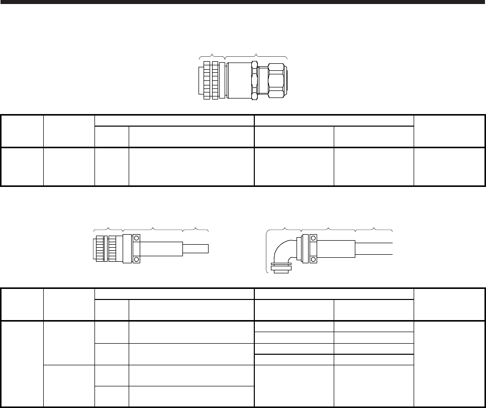
3. CONNECTORS USED FOR SERVO MOTOR WIRING
3 - 11
Plug Cable
clamp
Connector
configuration Feature
Plug (DDK) Cable clamp Servo motor
cooling fan
connector (Note)
Type Model Cable OD
[mm] (reference) Model
L
(for
cooling
fan)
IP67
EN
compliant
Straight CE05-6A14S-2SD-D
Applicable wire size: AWG 22 to 16 8.3 to 11.3 YSO14-9 to 11
(Daiwa Dengyo) CE05-2A14S-2P
Note. The connector to be mated.
Plug Cable clamp Cable Plug Cable clamp Cable
Connector
configuration Feature
Plug (DDK) Cable clamp (DDK) Servo motor
power supply
connector (Note)
Type Model Cable OD
[mm] (reference) Model
M
(for power
supply)
IP65
EN
UL/CSA
compliant
Straight CE05-6A24-10SD-D-BSS
Applicable wire size: AWG 10 to 8
13 to 15.5 CE3057-16A-2-D
CE05-2A24-10P
15 to 19.1 CE3057-16A-1-D
Angle CE05-8A24-10SD-D-BAS
Applicable wire size: AWG 10 to 8
13 to 15.5 CE3057-16A-2-D
15 to 19.1 CE3057-16A-1-D
General
environment
UL/CSA
compliant
Straight D/MS3106B24-10S
Applicable wire size: AWG 10 to 8 19.1 or less
(bushing ID) D/MS3057-16A
Angle D/MS3108B24-10S
Applicable wire size: AWG 10 to 8
Note. The connector to be mated.
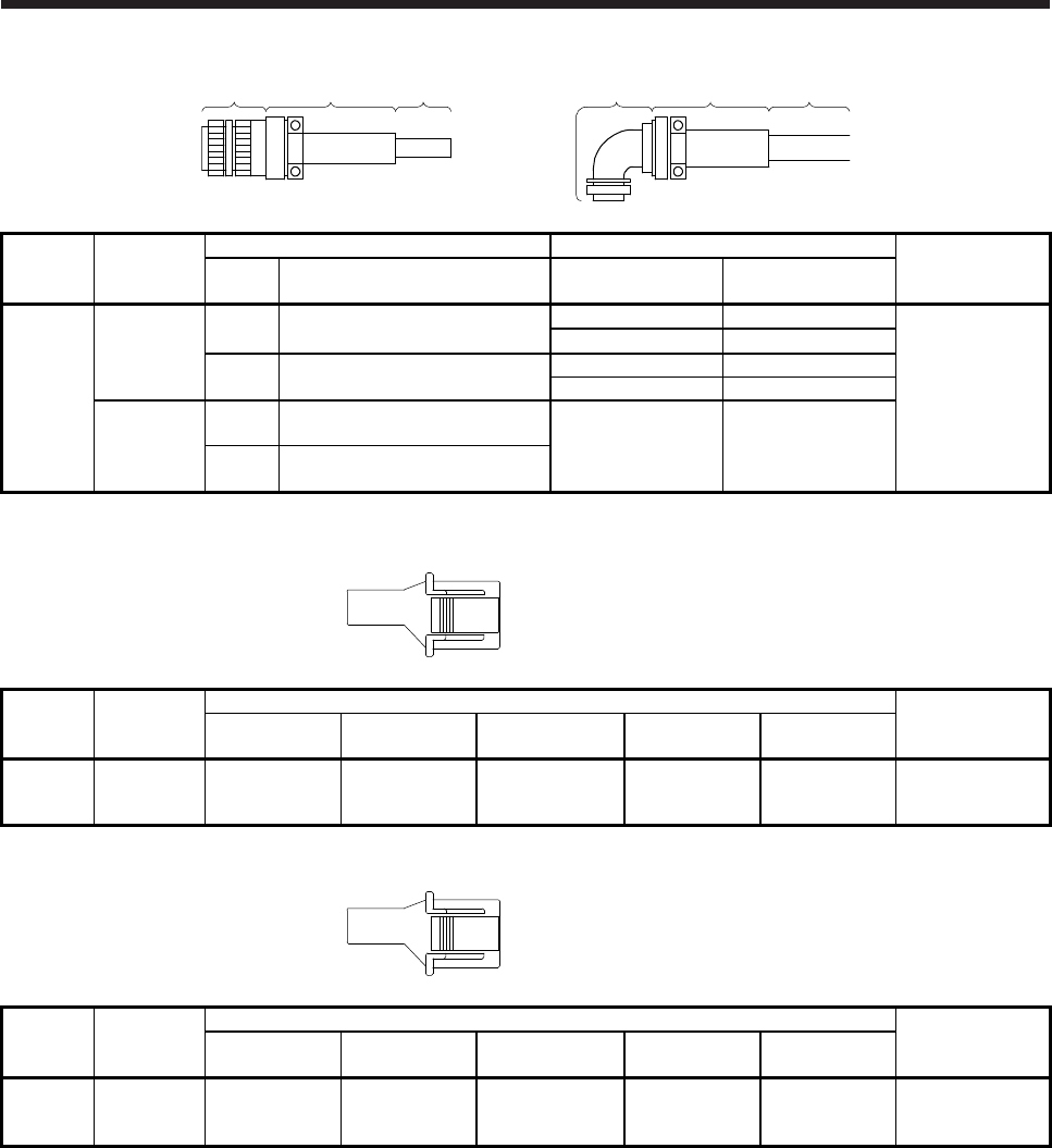
3. CONNECTORS USED FOR SERVO MOTOR WIRING
3 - 12
Plug Cable clamp Cable Plug Cable clamp Cable
Connector
configuration Feature
Plug (DDK) Cable clamp (DDK) Servo motor
power supply
connector (Note)
Type Model Cable OD
[mm] (reference) Model
N
(for power
supply)
IP65
EN
UL/CSA
compliant
Straight CE05-6A22-23SD-D-BSS
Applicable wire size: AWG 14 to 12
9.5 to 13 CE3057-12A-2-D
CE05-2A22-23P
12.5 to 16 CE3057-12A-1-D
Angle CE05-8A22-23SD-D-BAS
Applicable wire size: AWG 14 to 12
9.5 to 13 CE3057-12A-2-D
12.5 to 16 CE3057-12A-1-D
General
environment
UL/CSA
compliant
Straight D/MS3106B22-23S
Applicable wire size: AWG 14 to 12 15.9 or less
(bushing ID) D/MS3057-12A
Angle D/MS3108B22-23S
Applicable wire size: AWG 14 to 12
Note. The connector to be mated.
Connector
configuration Feature
Connector (JST)
Servo motor
encoder connector
Tab housing Tab contact Applicable wire size Insulator OD
[mm] Crimping tool
P
(for
encoder)
General
environment
(Note 1)
J21DPM-10V-KX SJ2M-01GF-
M1.0N
0.20 mm2 to 0.50
mm2
(AWG 24 to 20)
1.11 to 1.53 YRS-8861 J21DF-10V-KX-L
Note. Not comply with EN.
Connector
configuration Feature
Connector (JST)
Servo motor power
connector
Tab housing Tab contact Applicable wire size Insulator OD
[mm] Crimping tool
Q
(for power
supply)
General
environment
(Note 1)
J21DPM-06V-KX SJ2M-21GF-
M1.0N
0.30 mm2 to 0.75
mm2 1.30 to 1.90 YRF-1120 J21DF-06V-KX-L
Note. Not comply with EN.
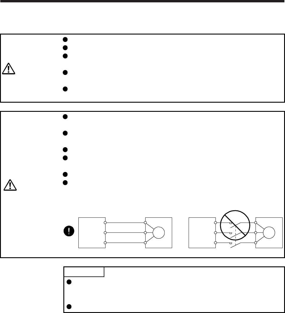
4. CONNECTION OF SERVO AMPLIFIER AND SERVO MOTOR
4 - 1
4. CONNECTION OF SERVO AMPLIFIER AND SERVO MOTOR
WARNING
Any person who is involved in wiring should be fully competent to do the work.
Ground the servo motor securely.
Do not attempt to wire the servo motor until it has been mounted. Otherwise, it
may cause an electric shock.
The cables should not be damaged, stressed, loaded, or pinched. Otherwise, it
may cause an electric shock.
To avoid an electric shock, insulate the connections of the power supply
terminals.
CAUTION
Wire the equipment correctly and securely. Otherwise, the servo motor may
operate unexpectedly, resulting in injury.
Connect cables to the correct terminals. Otherwise, a burst, damage, etc. may
occur.
Ensure that polarity (+/-) is correct. Otherwise, a burst, damage, etc. may occur.
Do not install a power capacitor, surge killer or radio noise filter (FR-BIF-(H)
option) with the power line of the servo motor.
Do not modify the equipment.
Connect the servo amplifier (converter unit) power output (U, V, and W) to the
servo motor power input (U, V, and W) directly. Do not let a magnetic contactor,
etc. intervene. Otherwise, it may cause a malfunction.
U
Servo motor
M
V
W
U
V
W
U
M
V
W
U
V
W
Servo amplifier
(converter unit) Servo motor
Servo amplifier
(converter unit)
POINT
We recommend using HIV wires to connect the servo amplifier (converter unit)
to the servo motor. Therefore, recommended wire sizes may different from those
of the used wires for the previous servo motors.
When you use a drive unit, "servo amplifier" explained above will be "drive unit".
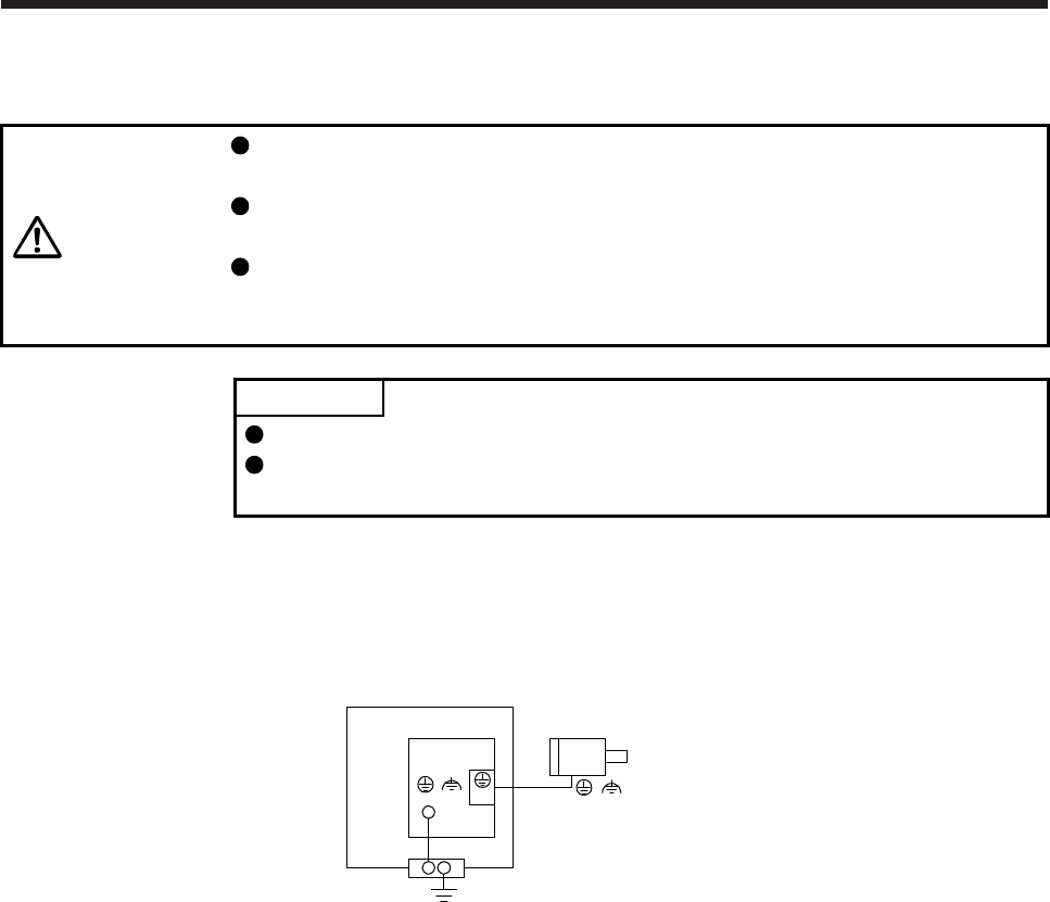
4. CONNECTION OF SERVO AMPLIFIER AND SERVO MOTOR
4 - 2
4.1 Connection instructions
CAUTION
To avoid a malfunction, connect the wires to the correct phase terminals (U, V,
and W) of the servo amplifier (converter unit) and servo motor.
Do not connect AC power supply directly to the servo motor. Otherwise, it may
cause a malfunction.
Do not use the 24 V DC interface power supply for the electromagnetic brake.
Always use the power supply designed exclusively for the electromagnetic brake.
Otherwise, it may cause a malfunction.
POINT
Refer to chapter 5 for the selection of the encoder cable.
Refer to the chapter of the servo motor series for the selection of a surge
absorber for the electromagnetic brake.
For grounding, connect the grounding lead wire from the servo motor to the protective earth (PE) terminal of
the servo amplifier (converter unit), and then connect the wire from the servo amplifier (converter unit) to the
ground via the protective earth of the cabinet. Do not connect the wire directly to the protective earth of the
cabinet.
Servo motor
Servo amplifier
(converter unit)
Cabinet
PE
terminal
(Note)
(
() )
(E)
Note. The number of PE terminals of the servo amplifier (converter unit) differs depending
on the amplifier types.
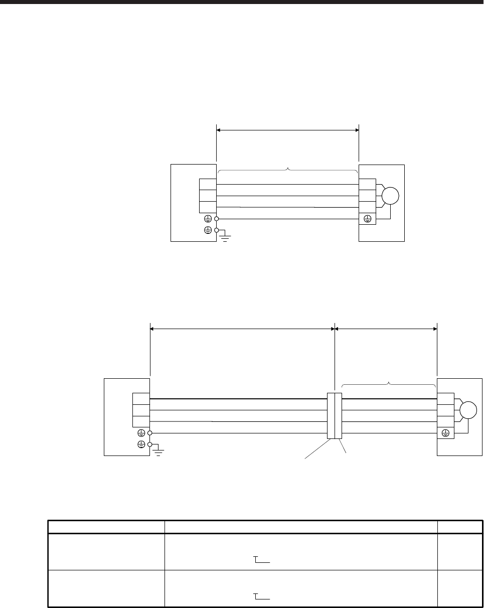
4. CONNECTION OF SERVO AMPLIFIER AND SERVO MOTOR
4 - 3
4.2 Wiring
4.2.1 HG-MR series/HG-KR series servo motor
(1) Connection with MR-J4 1-axis servo amplifier
(a) Servo motor power supply cable wiring diagrams
1) When cable length is 10 m or less
CNP3 (Red)
(White)
(Black)
(Green/yellow)
U
V
U
V
WW
Servo moto
r
Servo amplifier
10 m or less
M
MR-PWS1CBL_M-A1-L
MR-PWS1CBL_M-A2-L
MR-PWS1CBL_M-A1-H
MR-PWS1CBL_M-A2-H
2) When cable length exceeds 10 m
Fabricate an extension cable as shown below. In addition, the motor power supply cable should
be within 2 m.
Refer to section 4.3 for the wire used for the extension cable.
MR-PWS1CBL2M-A1-L
MR-PWS1CBL2M-A2-L
MR-PWS1CBL2M-A1-H
MR-PWS1CBL2M-A2-H
MR-PWS2CBL03M-A1-L
MR-PWS2CBL03M-A2-L
CNP3 (Red)
(White)
(Black)
(Green/yellow)
U
V
U
V
WW
Servo moto
r
Servo amplifier
M
Extension cable
50 m or less 2 m or less
(Note)
b) Junction connector for
motor power supply cable
(Note)
a) Junction connector for
extension cable
Note. Use of the following connectors is recommended when ingress protection (IP65) is necessary.
Connector: RM15WTPZ-4P(71)
Cord clamp: JR13WCC-5(72)
(Hirose Electric)
b) Junction connector for
motor power supply cable
a) Junction connector for
extension cable
Junction connector
Connector: RM15WTJZ-4S(71)
Cord clamp: JR13WCC-8(72)
(Hirose Electric)
Numeral changes depending on the cable OD.
Numeral changes depending on the cable OD.
Description IP rating
IP65
IP65
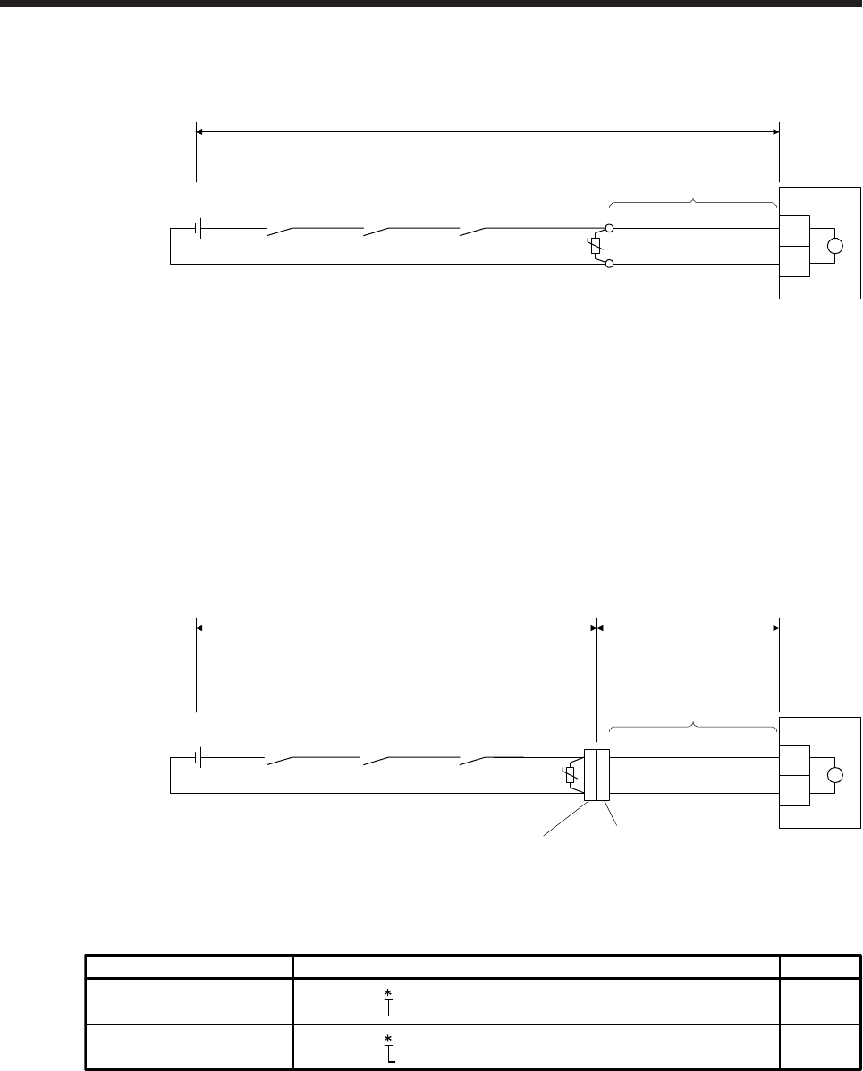
4. CONNECTION OF SERVO AMPLIFIER AND SERVO MOTOR
4 - 4
(b) Electromagnetic brake cable wiring diagrams
1) When cable length is 10 m or less
(Note 2)
(Note 3)
24 V DC power supply
for electromagnetic
brake
MBR
(Electromagnetic
brake interlock)
AWG20
AWG20
MR-BKS1CBL_M-A1-L
MR-BKS1CBL_M-A2-L
MR-BKS1CBL_M-A1-H
MR-BKS1CBL_M-A2-H
(Note 1) B1
B2
ALM
(Malfunction)
Servo motor
10 m or less
(Note 4)
UB
Note 1. Connect a surge absorber as close to the servo motor as possible.
2. There is no polarity in electromagnetic brake terminals (B1 and B2).
3. Do not use the 24 V DC interface power supply for the electromagnetic brake.
4. Create the circuit in order to shut off by interlocking with the emergency stop switch.
When fabricating the electromagnetic brake cable MR-BKS1CBL-_M-_, refer to section 5.5 and
5.6.
2) When cable length exceeds 10 m
Fabricate an extension cable as shown below. In addition, the electromagnetic brake cable
should be within 2 m.
Refer to section 4.3 for the wire used for the extension cable.
(Note 2)
b) Junction connector for
electromagnetic brake cable
(Note 2)
a) Junction connector for
extension cable
(Note 4)
(Note 5)
24 V DC power supply
for electromagnetic
brake
MBR
(Electromagnetic
brake interlock)
(Note 1)
ALM
(Malfunction)
Servo motor
(Note 3) AWG20 B1
B2 B
AWG20
2 m or less
Extension cable
(To be fabricated)
U
50 m or less
MR-BKS1CBL2M-A1-L
MR-BKS1CBL2M-A2-L
MR-BKS1CBL2M-A1-H
MR-BKS1CBL2M-A2-H
MR-BKS2CBL03M-A1-L
MR-BKS2CBL03M-A2-L
Note 1. Connect a surge absorber as close to the servo motor as possible.
2. Use of the following connectors is recommended when ingress protection (IP65) is necessary.
CM10-CR2P- (DDK)
Junction connector Description IP rating
IP65
IP65
CMV1-SP2S- (DDK)
a)
b)
Wire size: S, M, L
Wire size: S, M1, M2, L
Junction connector for
electromagnetic brake cable
Junction connector for
extension cable
3. Create the circuit in order to shut off by interlocking with the emergency stop switch.
4. There is no polarity in electromagnetic brake terminals (B1 and B2).
5. Do not use the 24 V DC interface power supply for the electromagnetic brake.
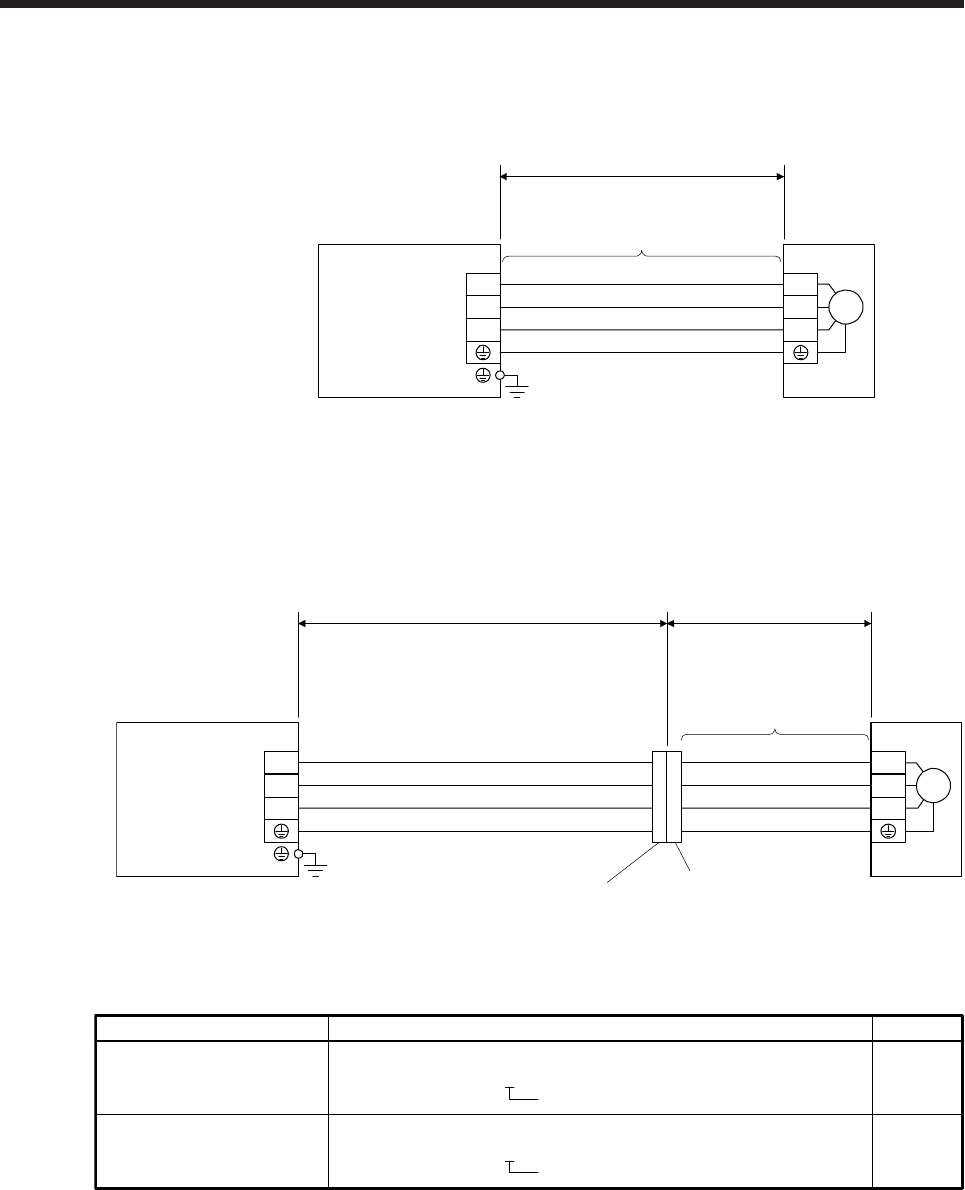
4. CONNECTION OF SERVO AMPLIFIER AND SERVO MOTOR
4 - 5
(2) Connection with MR-J4 multi-axis servo amplifier
(a) Servo motor power supply cable wiring diagrams
1) When cable length is 10 m or less
CNP3A/CNP3B/
CNP3C
(Note)
(Red)
(White)
(Black)
(Green/yellow)
U
V
W
U
V
W
Servo motorServo amplifier
10 m or less
M
MR-PWS1CBL_M-A1-L
MR-PWS1CBL_M-A2-L
MR-PWS1CBL_M-A1-H
MR-PWS1CBL_M-A2-H
Note. CNP3 is for the MR-J4 3-axis servo amplifier.
2) When cable length exceeds 10 m
Fabricate an extension cable as shown below. In addition, the motor power supply cable should
be within 2 m.
Refer to section 4.3 for the wire used for the extension cable.
(Note 2)
b) Junction connector for
motor power supply cable
(Note 2)
a) Junction connector for
extension cable
MR-PWS1CBL2M-A1-L
MR-PWS1CBL2M-A2-L
MR-PWS1CBL2M-A1-H
MR-PWS1CBL2M-A2-H
MR-PWS2CBL03M-A1-L
MR-PWS2CBL03M-A2-L
(Red)
(White)
(Black)
(Green/yellow)
Extension cable
50 m or less 2 m or less
CNP3A/CNP3B/
CNP3C
(Note 1) U
V
W
U
V
W
Servo motorServo amplifier
M
Note 1. CNP3 is for the MR-J4 3-axis servo amplifier.
2. Use of the following connectors is recommended when ingress protection (IP65) is necessary.
Connector: RM15WTPZ-4P(71)
Cord clamp: JR13WCC-5(72)
(Hirose Electric)
b) Junction connector for
motor power supply cable
a) Junction connector for
extension cable
Junction connector
Connector: RM15WTJZ-4S(71)
Cord clamp: JR13WCC-8(72)
(Hirose Electric)
Numeral changes depending on the cable OD.
Numeral changes depending on the cable OD.
Description IP rating
IP65
IP65
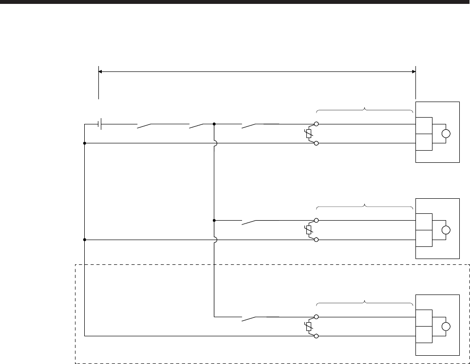
4. CONNECTION OF SERVO AMPLIFIER AND SERVO MOTOR
4 - 6
(b) Electromagnetic brake cable wiring diagrams
1) When cable length is 10 m or less
MR-BKS1CBL_M-A1-L
MR-BKS1CBL_M-A2-L
MR-BKS1CBL_M-A1-H
MR-BKS1CBL_M-A2-H
(Note 1)
(Note 2)
(Note 2)
AWG20
AWG20
(Note 1) B1
B2
Servo motor
10 m or less
UB
AWG20
AWG20 B1
B2
Servo motor
UB
MBR-A
(Electromagnetic
brake interlock
for A-axis)
CALM
(AND
malfunction)
MBR-B
(Electromagnetic
brake interlock
for B-axis)
(Note 4)
24 V DC power supply
for electromagnetic
brake (Note 3)
(Note 1)
(Note 2)
AWG20
AWG20 B1
B2
Servo motor
UB
MBR-C
(Electromagnetic
brake interlock
for C-axis)
(Note 5)
MR-BKS1CBL_M-A1-L
MR-BKS1CBL_M-A2-L
MR-BKS1CBL_M-A1-H
MR-BKS1CBL_M-A2-H
MR-BKS1CBL_M-A1-L
MR-BKS1CBL_M-A2-L
MR-BKS1CBL_M-A1-H
MR-BKS1CBL_M-A2-H
Note 1. Connect a surge absorber as close to the servo motor as possible.
2. There is no polarity in electromagnetic brake terminals (B1 and B2).
3. Create the circuit in order to shut off by interlocking with the emergency stop switch.
4. Do not use the 24 V DC interface power supply for the electromagnetic brake.
5. This connection is for the MR-J4 3-axis servo amplifier.
When fabricating the electromagnetic brake cable MR-BKS1CBL-_M-_, refer to section 5.5 and
5.6.
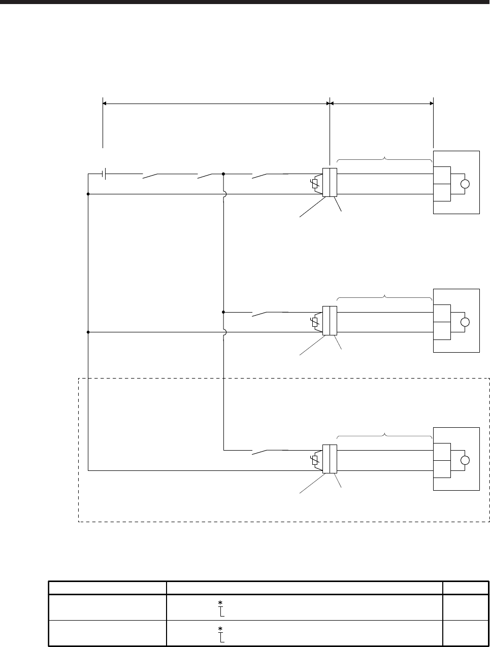
4. CONNECTION OF SERVO AMPLIFIER AND SERVO MOTOR
4 - 7
2) When cable length exceeds 10 m
Fabricate an extension cable as shown below. In addition, the electromagnetic brake cable
should be within 2 m.
Refer to section 4.3 for the wire used for the extension cable.
MBR-A
(Electromagnetic
brake interlock
for A-axis)
CALM
(AND
malfunction)
MBR-B
(Electromagnetic
brake interlock
for B-axis)
(Note 3)
MBR-C
(Electromagnetic
brake interlock
for C-axis)
(Note 1)
(Note 4)
(Note 4)
(Note 1)
Servo motor
Servo motor
(Note 5)
24 V DC power supply
for electromagnetic
brake
(Note 1)
(Note 4)
Servo motor
(Note 6)
U
U
U
B1
B2 B
AWG20
AWG20
2 m or less50 m or less
B1
B2 B
AWG20
AWG20
B1
B2 B
AWG20
AWG20
MR-BKS1CBL2M-A1-L
MR-BKS1CBL2M-A2-L
MR-BKS1CBL2M-A1-H
MR-BKS1CBL2M-A2-H
MR-BKS2CBL03M-A1-L
MR-BKS2CBL03M-A2-L
MR-BKS1CBL2M-A1-L
MR-BKS1CBL2M-A2-L
MR-BKS1CBL2M-A1-H
MR-BKS1CBL2M-A2-H
MR-BKS2CBL03M-A1-L
MR-BKS2CBL03M-A2-L
MR-BKS1CBL2M-A1-L
MR-BKS1CBL2M-A2-L
MR-BKS1CBL2M-A1-H
MR-BKS1CBL2M-A2-H
MR-BKS2CBL03M-A1-L
MR-BKS2CBL03M-A2-L
(Note 2)
b) Junction connector for
electromagnetic brake cable
(Note 2)
a) Junction connector for
extension cable
(Note 2)
b) Junction connector for
electromagnetic brake cable
(Note 2)
a) Junction connector for
extension cable
(Note 2)
b) Junction connector for
electromagnetic brake cable
(Note 2)
a) Junction connector for
extension cable
Note 1. Connect a surge absorber as close to the servo motor as possible.
2. Use of the following connectors is recommended when ingress protection (IP65) is necessary.
CM10-CR2P- (DDK)
Junction connector Description IP rating
IP65
IP65
CMV1-SP2S- (DDK)
a)
b)
Wire size: S, M, L
Wire size: S, M1, M2, L
Junction connector for
electromagnetic brake cable
Junction connector for
extension cable
3. Create the circuit in order to shut off by interlocking with the emergency stop switch.
4. There is no polarity in electromagnetic brake terminals (B1 and B2).
5. Do not use the 24 V DC interface power supply for the electromagnetic brake.
6. This connection is for the MR-J4 3-axis servo amplifier.
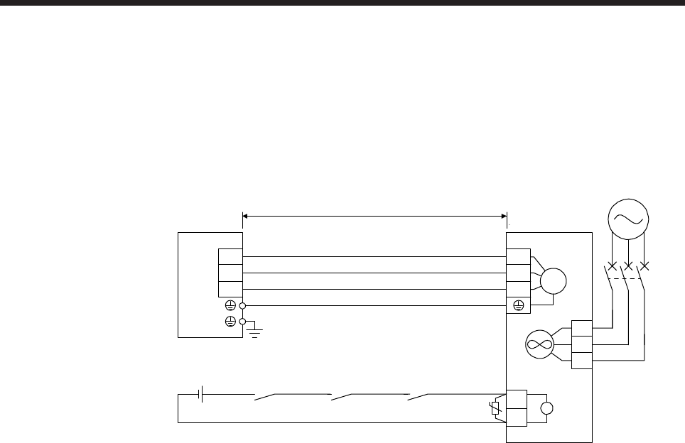
4. CONNECTION OF SERVO AMPLIFIER AND SERVO MOTOR
4 - 8
4.2.2 HG-SR series/HG-JR series/HG-RR series/HG-UR series servo motor
Refer to section 4.3 for the wires used for wiring.
(1) Wiring diagrams
(a) Connection with MR-J4 1-axis servo amplifier
U
V
W
50 m or less
Servo amplifier
(Note 3)
RA3 (Note 1)
B1
B2
(Note 2)
24 V DC power supply
for electromagnetic
brake
ALM
(Malfunction)
RA1
MBR
(Electromagnetic
brake interlock)
RA2
UB
U
V
WM
Servo motor
Cooling fan
BU
BV
BW
MCCB
(Note 4)
Power supply
cooling fan
Note 1. There is no polarity in electromagnetic brake terminals (B1 and B2).
2. Do not use the 24 V DC interface power supply for the electromagnetic brake.
3. Create the circuit in order to shut off by interlocking with the emergency stop switch.
4. Refer to the chapter of the servo motor series for the cooling fan power supply.
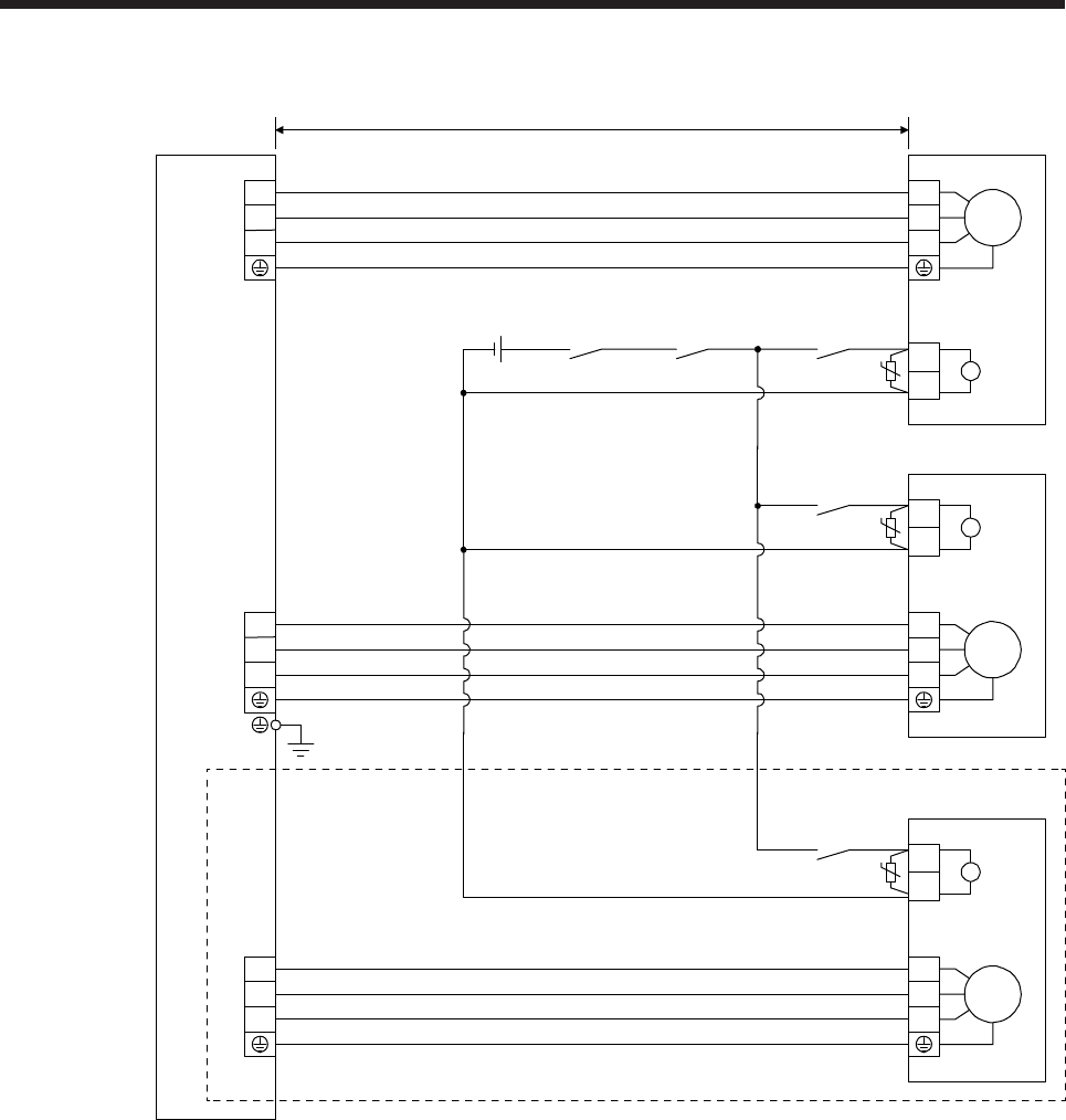
4. CONNECTION OF SERVO AMPLIFIER AND SERVO MOTOR
4 - 9
(b) Connection with MR-J4 multi-axis servo amplifier
50 m or less
A-axis servo motor
M
U
V
W
(Note 1)
B1
B2
UB
Servo amplifier
U
V
W
CNP3A
(Note 3)
CALM
(AND
malfunction)
RA1
MBR-A
(Electromagnetic
brake interlock
for A-axis)
RA2
CNP3B
U
V
W
B-axis servo motor
(Note 1)
B1
B2
UB
MBR-B
(Electromagnetic
brake interlock
for B-axis)
RA3
M
U
V
W
(Note 2)
24 V DC power supply
for electromagnetic
brake
CNP3C
U
V
W
C-axis servo motor
(Note 1)
B1
B2
UB
MBR-C
(Electromagnetic
brake interlock
for C-axis)
RA4
M
U
V
W
Note 1. There is no polarity in electromagnetic brake terminals (B1 and B2).
2. Do not use the 24 V DC interface power supply for the electromagnetic brake.
3. Create the circuit in order to shut off by interlocking with the emergency stop switch.
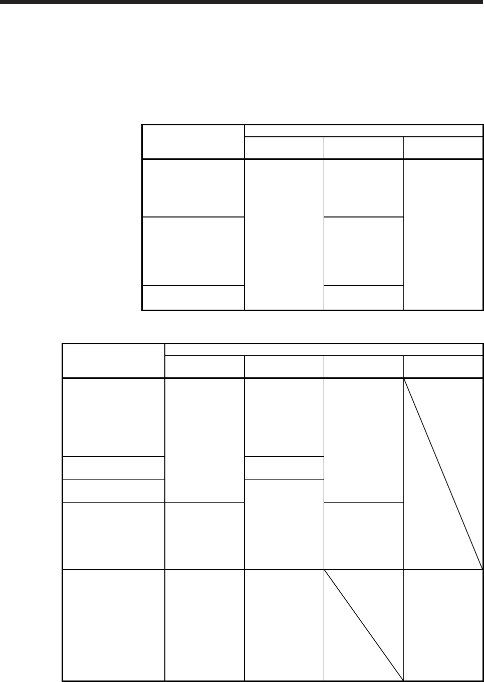
4. CONNECTION OF SERVO AMPLIFIER AND SERVO MOTOR
4 - 10
(2) Servo motor terminal section
The following table shows the servo motor terminal section. For details of the connectors, refer to (3) of
this section. For details of the terminal box, refer to (4) of this section.
The connector fitting the servo motor is prepared as options. Refer to chapter 5 for details of the options.
For types other than those prepared as options, refer to chapter 3.
(a) HG-SR series
Servo motor
Servo motor terminal section
Encoder Power
Electromagnetic
brake
HG-SR52(4)
HG-SR102(4)
HG-SR152(4)
HG-SR51
HG-SR81
Connector A
Connector C
Connector H
HG-SR202(4)
HG-SR352(4)
HG-SR502(4)
HG-SR121
HG-SR201
HG-SR301
Connector D
HG-SR702(4)
HG-SR421 Connector E
(b) HG-JR series
Servo motor
Servo motor terminal section
Encoder Power
Electromagnetic
brake Cooling fan
HG-JR53(4)
HG-JR73(4)
HG-JR103(4)
HG-JR153(4)
HG-JR203(4)
HG-JR3534
HG-JR5034
Connector A
Connector C
Connector H
HG-JR353
HG-JR503 Connector D
HG-JR703(4)
HG-JR903(4)
Connector E
HG-JR701M(4)
HG-JR11K1M(4)
HG-JR15K1M(4)
HG-JR601(4)
HG-JR801(4)
HG-JR12K1(4)
Connector B Connector J
HG-JR22K1M(4)
HG-JR30K1M(4)
HG-JR37K1M(4)
HG-JR45K1M4
HG-JR55K1M4
HG-JR15K1(4)
HG-JR20K1(4)
HG-JR25K1(4)
HG-JR30K1(4)
HG-JR37K1(4)
Connector L Terminal box Connector K
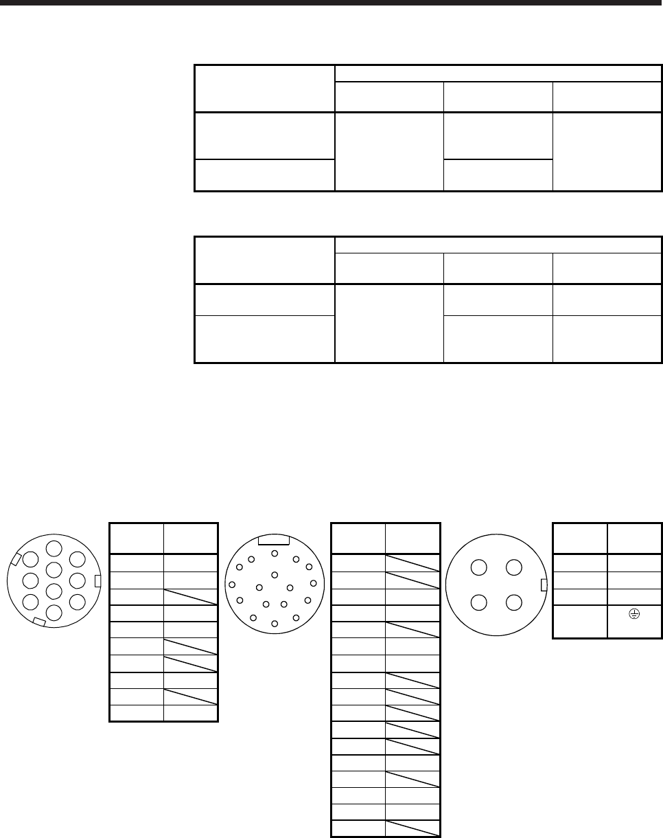
4. CONNECTION OF SERVO AMPLIFIER AND SERVO MOTOR
4 - 11
(c) HG-RR series
Servo motor
Servo motor terminal section
Encoder Power
Electromagnetic
brake
HG-RR103
HG-RR153
HG-RR203 Connector A
Connector F The connector for
power is shared
HG-RR353
HG-RR503 Connector G
(d) HG-UR series
Servo motor
Servo motor terminal section
Encoder Power
Electromagnetic
brake
HG-UR72
HG-UR152
Connector A
Connector F The connector for
power is shared
HG-UR202
HG-UR352
HG-UR502
Connector G Connector J
(3) Details of servo motor-side connectors
The followings show the encoder connector, power connector, electromagnetic brake connector, and
cooling fan connector viewed from the connection side.
Connector A
Encoder connector
CMV1-R10P
Connector B
Encoder connector
MS3102A20-29P
Connector C
Power supply connector
MS3102A18-10P
5
6
1
4
3
2
8
7
9
10
Terminal
No. Signal
A
N
G
S R
T P
HF
JE
KD
LMBC
Pin Signal
CD
AB
Terminal
No. Signal
1 MR A A U
2 MRR B B V
3 C MR C W
4 BAT D MRR D
5 LG E (PE)
6 F BAT
7 G LG
8 P5 H
9 J
10 SHD K
L
M
N SHD
P
R LG
S P5
T
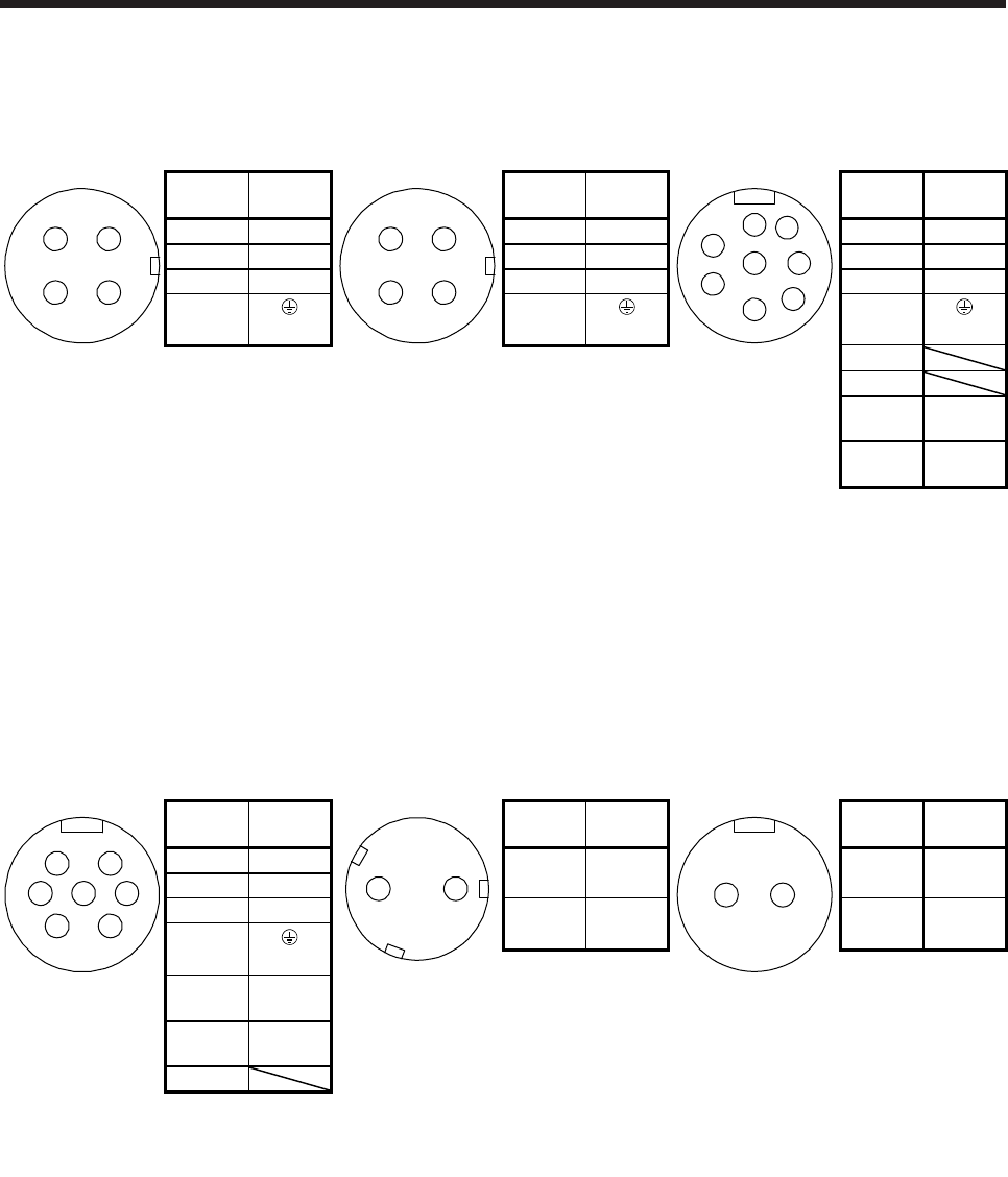
4. CONNECTION OF SERVO AMPLIFIER AND SERVO MOTOR
4 - 12
Connector D
Power supply connector
MS3102A22-22P
Connector E
Power supply connector
MS3102A32-17P
Connector F
Power supply connector
CE05-2A22-23P
CD
AB
Terminal
No. Signal
CD
AB
Terminal
No. Signal
F
E
D
H
GA
B
C
Terminal
No. Signal
A U A U A U
B V B V B V
C W C W C W
D D D
(PE) (PE) (PE)
E
F
G
B1
(Note)
H B2
(Note)
Note. For the motor
with an
electromagnetic
brake, supply
electromagnetic
brake power (24
V DC). There is
no polarity.
Connector G
Power supply connector
CE05-2A24-10P
Connector H
Electromagnetic brake connector
CMV1-R2P
Connector J
Electromagnetic brake connector
MS3102A10SL-4P
F
E
D
G
C
B
A
Terminal
No. Signal
12
Terminal
No. Signal
AB
Terminal
No. Signal
A U 1 B1
(Note) A B1
(Note)
B V
C W 2 B2
(Note) B B2
(Note)
D
(PE) Note. For the motor
with an
electromagnetic
brake, supply
electromagnetic
brake power
(24 V DC).
There is no
polarity.
Note. For the motor
with an
electromagnetic
brake, supply
electromagnetic
brake power
(24 V DC).
There is no
polarity.
E B1
(Note)
F B2
(Note)
G
Note. For the motor
with an
electromagnetic
brake, supply
electromagnetic
brake power (24
V DC). There is
no polarity.
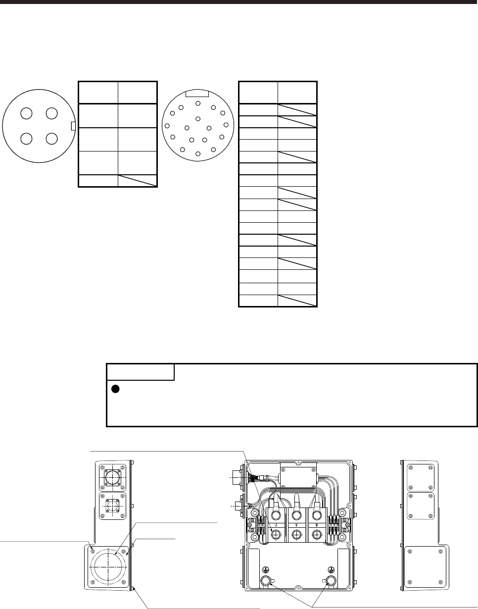
4. CONNECTION OF SERVO AMPLIFIER AND SERVO MOTOR
4 - 13
Connector K
Cooling fan connector
CE05-2A14S-2P
Connector L
Encoder connector
MS3102A20-29P
CD
AB
Terminal
No. Signal
A
N
G
S R
T P
HF
JE
KD
LMBC
Pin Signal
A BU
(Note)
A
B
B BV
(Note)
C MR
D MRR
C BW
(Note)
E
F BAT
D G LG
Note. Refer to the
chapter of the
servo motor
series for the
specifications of
the power
supplied to the
cooling fan.
H
J
K THM1
L THM2
M
N SHD
P
R LG
S P5
T
(4) Terminal box inside
HG-JR22K1M(4) to HG-JR37K1M(4)/HG-JR45K1M4/HG-JR55K1M4/HG-JR15K1(4) to HG-JR37K1(4)
POINT
The terminal box of the HG-JR22K1M(4) servo motor has been changed since
September 2014. Refer to appendix 9 for the terminal box detail diagram before
change.
Terminal box lid: M4 screw (10)
Keep plate
Power lead hole (Note)
Keep plate: M5 screw (4)
Power supply terminal block: M10 screw (3)
Protective earth (PE) terminal: M10 screw (2)
Note. Provide measures to prevent oil, water, dust and dirt from entering the servo motor through the power lead hole.
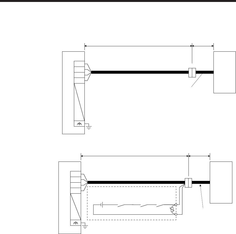
4. CONNECTION OF SERVO AMPLIFIER AND SERVO MOTOR
4 - 14
4.2.3 HG-AK series servo motor
(1) Connection with MR-J4-03A6(-RJ) servo amplifier
(a) Motor power cable wiring diagram (without electromagnetic brake)
CNP1 Power cable supplied
with the servo motor
Servo motorServo amplifier
30 m or less 0.2 m
MR-J4W03PWCBL_M-H
U
V
W
E
(b) Motor power cable wiring diagram (with electromagnetic brake)
Power cable supplied
with the servo motor
(Note 3)
24 V DC power
supply for
electromagnetic
brake
ALM
(Malfunction)
RA1
MBR
(Electromagnetic
brake interlock)
RA2
U
(Note 4)
(Note 1)
Fabricate it.
(Note 3)
CNP1
U
V
W
E(Note 2)
Servo motorServo amplifier
30 m or less 0.2 m
MR-J4W03PWBRCBL_M-H
Note 1. Connect a surge absorber as close to the servo motor as possible.
2. There is no polarity in electromagnetic brake terminals (B1 and B2).
3. Do not use the 24 V DC interface power supply for the electromagnetic brake.
4. Create the circuit in order to shut off by interlocking with the emergency stop switch.
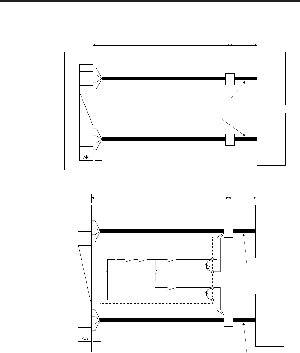
4. CONNECTION OF SERVO AMPLIFIER AND SERVO MOTOR
4 - 15
(2) Connection with MR-J4W2-0303B6 servo amplifier
(a) Motor power cable wiring diagram (without electromagnetic brake)
Power cable supplied
with the servo motor B-axis servo motor
MR-J4W03PWCBL_M-H
CNP1
A-axis servo motorServo amplifier
30 m or less 0.2 m
MR-J4W03PWCBL_M-H
U1
V1
W1
E1
U2
V2
W2
E2
(b) Motor power cable wiring diagram (with electromagnetic brake)
Power cable supplied
with the servo motor
CNP1
A-axis servo motorServo amplifier
30 m or less 0.2 m
MR-J4W03PWBRCBL_M-H
(Note 3)
24 V DC power
supply for
electromagnetic
brake
MBR-A
(Electromagnetic brake
interlock for A-axis)
RA2
U
CALM
(AND malfunction)
(Note 1)
Fabricate it.
(Note 3)
MBR-B
(Electromagnetic brake
interlock for B-axis)
RA4
U
(Note 1) (Note 3)
Power cable supplied
with the servo motor
B-axis servo motor
MR-J4W03PWBRCBL_M-H
(Note 2)
(Note 2)
U1
V1
W1
E1
U2
V2
W2
E2
(Note 4)
Note 1. Connect a surge absorber as close to the servo motor as possible.
2. There is no polarity in electromagnetic brake terminals (B1 and B2).
3. Do not use the 24 V DC interface power supply for the electromagnetic brake.
4. Create the circuit in order to shut off by interlocking with the emergency stop switch.
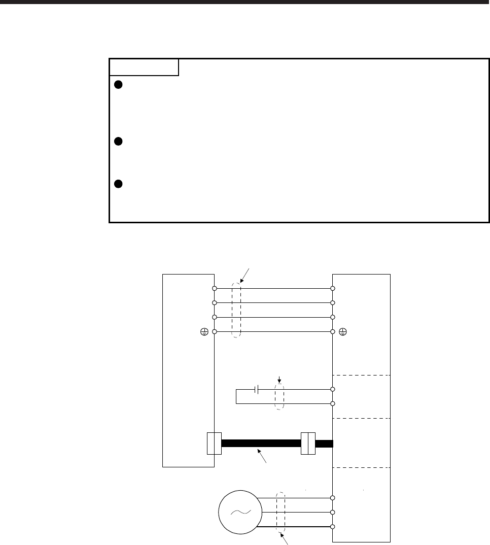
4. CONNECTION OF SERVO AMPLIFIER AND SERVO MOTOR
4 - 16
4.3 Selection example of wires
POINT
Wires indicated in this section are separated wires. When using a cable for
power line (U, V, and W) between the servo amplifier and servo motor, use a
600 V grade EP rubber insulated chloroprene sheath cab-tire cable (2PNCT).
For selection of cables, refer to appendix 6.
To comply with the UL/CSA standard, use the wires shown in appendix 4 for
wiring. To comply with other standards, use a wire that is complied with each
standard.
Selection condition of wire size is as follows.
Construction condition: Single wire set in midair
Wire length: 30 m or less
The following diagram shows the wires used for wiring. Use the wires given in this section or equivalent.
U
V
W
U
V
W
B1
B2
BU
BV
BW
Power supply
3) Cooling fan lead
Cooling fan
2) Electromagnetic
brake lead
Servo motor
1) Servo motor power lead
Servo amplifier
Motor
Electromagnetic
brake
Encoder
Encoder cable
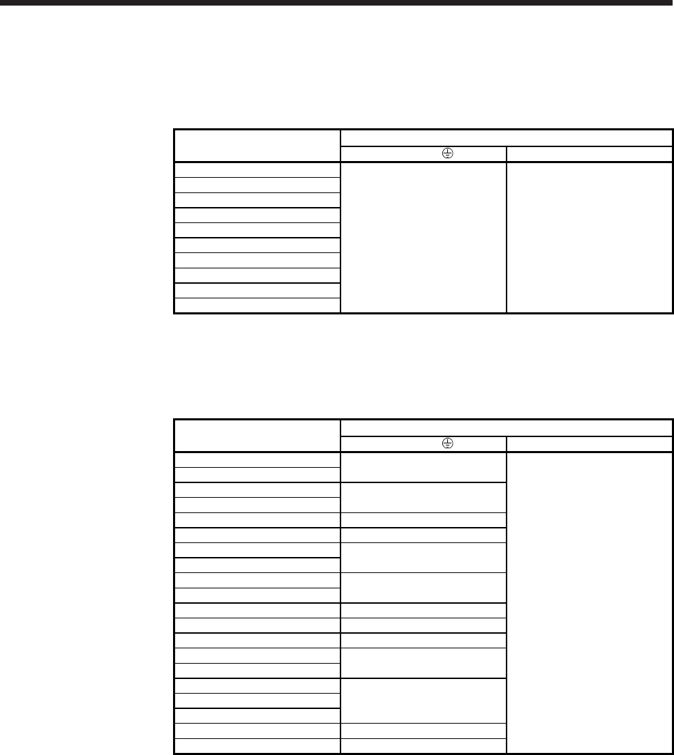
4. CONNECTION OF SERVO AMPLIFIER AND SERVO MOTOR
4 - 17
When using the 600 V Grade heat-resistant polyvinyl chloride insulated wire (HIV wire)
Selection example of wire size when using HIV wires is indicated below.
(1) HG-MR series and HG-KR series
Servo motor Wires [mm2]
1) U/V/W/ 2) B1/B2
HG-MR053
HG-MR13
HG-MR23
HG-MR43
HG-MR73 0.75 (AWG 18) (Note 1, 2) 0.5 (AWG 20) (Note 1)
HG-KR053
HG-KR13
HG-KR23
HG-KR43
HG-KR73
Note 1. It is for wire length of 10 m or less. When fabricating an extension cable, use 1.25 mm2
(AWG 16).
2. For the motor power connector wiring, use fluorine resin wire of 0.75 mm2 (AWG 18).
(2) HG-SR series
Servo motor Wires [mm2]
1) U/V/W/ 2) B1/B2
HG-SR51 1.25 (AWG 16)
1.25 (AWG 16)
HG-SR81
HG-SR121 2 (AWG 14)
HG-SR201
HG-SR301 3.5 (AWG 12)
HG-SR421 5.5 (AWG 10) (Note)
HG-SR52 1.25 (AWG 16)
HG-SR102
HG-SR152 2 (AWG 14)
HG-SR202
HG-SR352 3.5 (AWG 12)
HG-SR502 5.5 (AWG 10) (Note)
HG-SR702 8 (AWG 8) (Note)
HG-SR524 1.25 (AWG 16)
HG-SR1024
HG-SR1524
2 (AWG 14)
HG-SR2024
HG-SR3524
HG-SR5024 3.5 (AWG 12) (Note)
HG-SR7024 5.5 (AWG 10) (Note)
Note. Refer to each servo amplifier instruction manual for crimp terminals and crimping tools used for
connection with the servo amplifier.
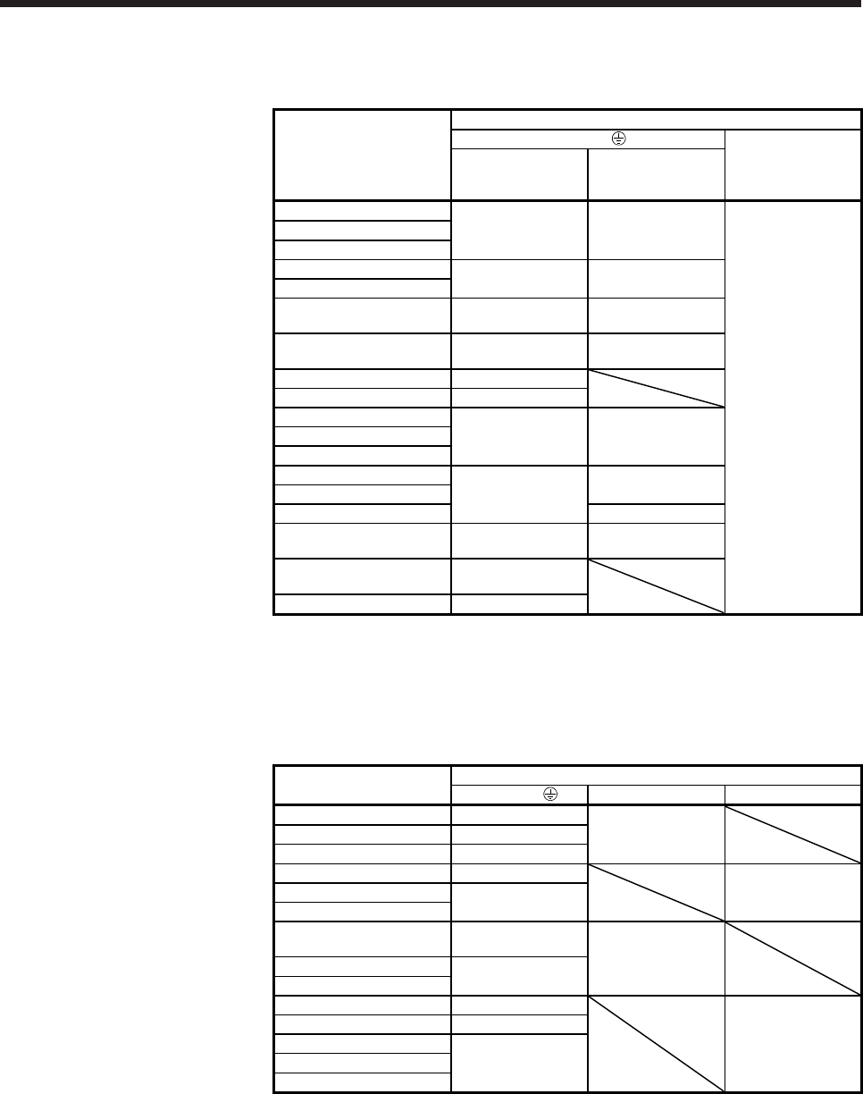
4. CONNECTION OF SERVO AMPLIFIER AND SERVO MOTOR
4 - 18
(3) HG-JR series
(a) 3000 r/min series
Servo motor
Wires [mm
2
]
1) U/V/W/
2) B1/B2
Standard
When the
maximum torque is
400% (Note 2)
HG-JR53
1.25 (AWG 16) 1.25 (AWG 16)
1.25 (AWG 16)
HG-JR73
HG-JR103
HG-JR153 2 (AWG 14) 2 (AWG 14)
HG-JR203
HG-JR353 3.5 (AWG 12) 3.5 (AWG 12)
(Note 1)
HG-JR503 5.5 (AWG 10)
(Note 1)
5.5 (AWG 10)
(Note 1)
HG-JR703 8 (AWG 8) (Note 1)
HG-JR903 14 (AWG 6) (Note 1)
HG-JR534
1.25 (AWG 16) 1.25 (AWG 16)
HG-JR734
HG-JR1034
HG-JR1534
2 (AWG 14)
HG-JR2034 2 (AWG 14)
HG-JR3534 2 (AWG 14) (Note 1)
HG-JR5034 3.5 (AWG 12)
(Note 1)
3.5 (AWG 12)
(Note 1)
HG-JR7034 5.5 (AWG 10)
(Note 1)
HG-JR9034 8 (AWG 8) (Note 1)
Note 1. Refer to each servo amplifier instruction manual for crimp terminals and crimping
tools used for connection with the servo amplifier.
2. The maximum torque can be increased to 400% by changing the servo amplifier.
Refer to section 8.2 for the combinations.
(b) 1500 r/min series
Servo motor Wires [mm
2
]
1) U/V/W/ 2) B1/B2 3) BU/BV/BW
HG-JR701M 8 (AWG 8) (Note)
HG-JR11K1M 14 (AWG 6) (Note) 1.25 (AWG 16)
HG-JR15K1M 22 (AWG 4) (Note)
HG-JR22K1M 38 (AWG 2) (Note)
HG-JR30K1M 60 (AWG 2/0)
(Note)
1.25 (AWG 16)
HG-JR37K1M
HG-JR701M4 3.5 (AWG 12)
(Note) 1.25 (AWG 16)
HG-JR11K1M4 8 (AWG 8) (Note)
HG-JR15K1M4
HG-JR22K1M4 14 (AWG 6) (Note)
HG-JR30K1M4 22 (AWG 4) (Note)
HG-JR37K1M4 1.25 (AWG 16)
HG-JR45K1M4 38 (AWG 2) (Note)
HG-JR55K1M4
Note. Refer to each servo amplifier instruction manual for crimp terminals and crimping tools
used for connection with the servo amplifier.
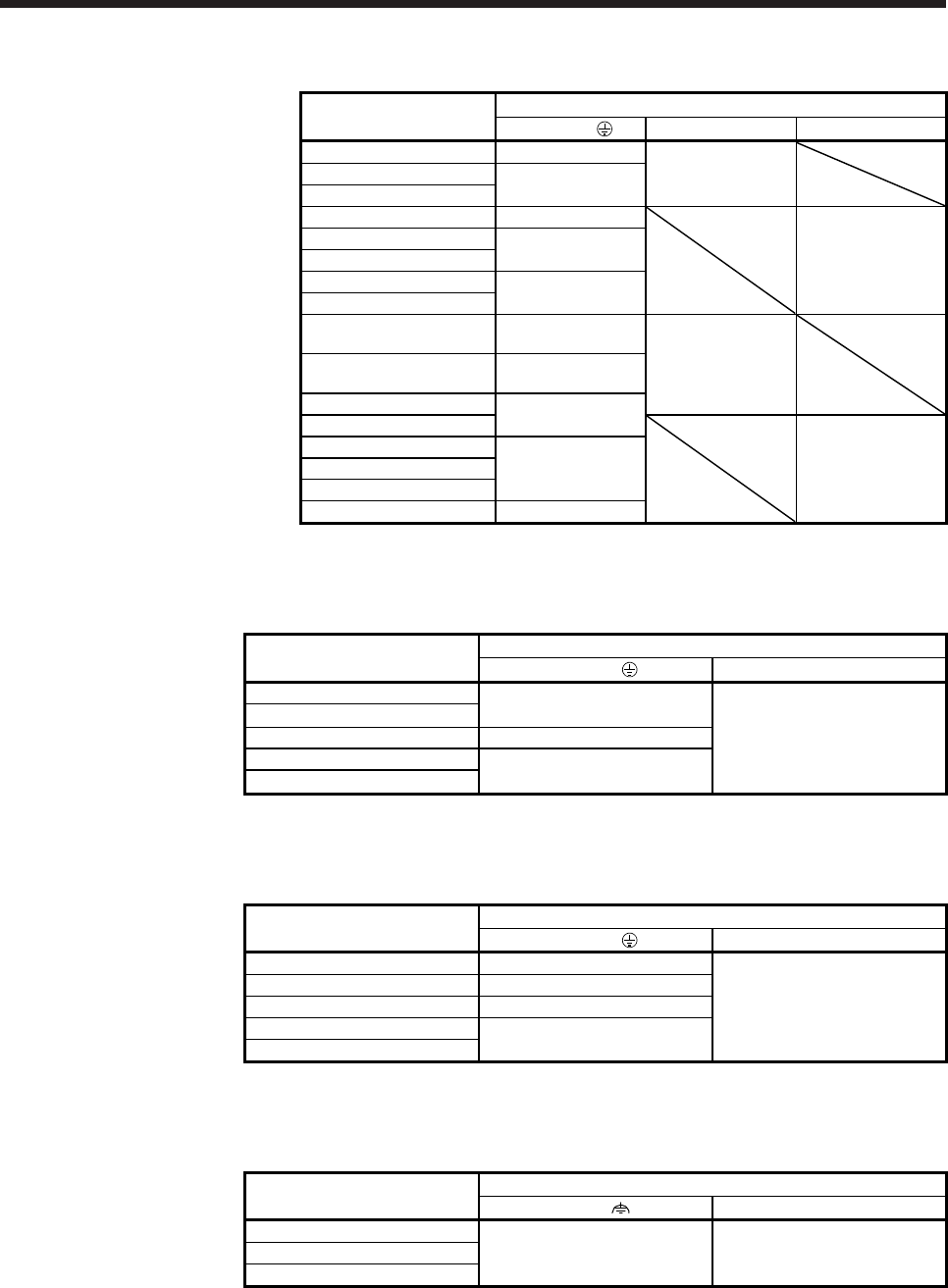
4. CONNECTION OF SERVO AMPLIFIER AND SERVO MOTOR
4 - 19
(c) 1000 r/min series
Servo motor Wires [mm2]
1) U/V/W/ 2) B1/B2 3) BU/BV/BW
HG-JR601 8 (AWG 8) (Note)
HG-JR801 14 (AWG 6) (Note) 1.25 (AWG 16)
HG-JR12K1
HG-JR15K1 22 (AWG 4) (Note)
HG-JR20K1 38 (AWG 2) (Note)
HG-JR25K1 1.25 (AWG 16)
HG-JR30K1 60 (AWG 2/0)
(Note)
HG-JR37K1
HG-JR6014 3.5 (AWG 12)
(Note)
1.25 (AWG 16)
HG-JR8014 5.5 (AWG 10)
(Note)
HG-JR12K14 8 (AWG 8) (Note)
HG-JR15K14
HG-JR20K14
HG-JR25K14 14 (AWG 6) (Note) 1.25 (AWG 16)
HG-JR30K14
HG-JR37K14 22 (AWG 4) (Note)
Note. Refer to each servo amplifier instruction manual for crimp terminals and crimping tools
used for connection with the servo amplifier.
(4) HG-RR series
Servo motor Wires [mm2]
1) U/V/W/ 2) B1/B2
HG-RR103 2 (AWG 14)
HG-RR153
HG-RR203 3.5 (AWG 12) 1.25 (AWG 16)
HG-RR353 5.5 (AWG 10) (Note)
HG-RR503
Note. Refer to each servo amplifier instruction manual for crimp terminals and crimping tools used for
connection with the servo amplifier.
(5) HG-UR series
Servo motor Wires [mm2]
1) U/V/W/ 2) B1/B2
HG-UR72 1.25 (AWG 16)
HG-UR152 2 (AWG 14)
HG-UR202 3.5 (AWG 12) 1.25 (AWG 16)
HG-UR352 5.5 (AWG 10) (Note)
HG-UR502
Note. Refer to each servo amplifier instruction manual for crimp terminals and crimping tools used for
connection with the servo amplifier.
(6) HG-AK series
Servo motor Wire [mm2]
U/V/W/ 2) B1/B2
HG-AK0136
HG-AK0236 0.75 (AWG 19) (Note 1, 2) 0.75 (AWG 19) (Note 3, 4)
HG-AK0336
Note 1. For the servo motor power connector wiring, use fluorine resin wire of 0.75 mm2 (AWG 19).
2. It is for wire length of 5 m or less. For over 5 m, the short-duration running range in the
torque characteristics may be lower because of voltage drop.
3. For the electromagnetic connector wiring, use fluorine resin wire of 0.75 mm2 (AWG 19).
4. It is for wire length of 5 m or less. For over 5 m, use HIV wires of 3.5 mm2 (AWG12) to
extend the wiring.
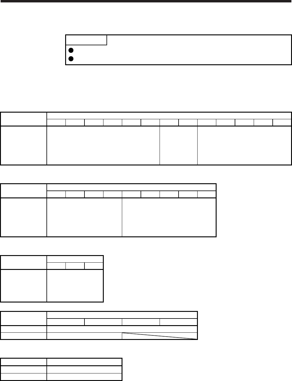
4. CONNECTION OF SERVO AMPLIFIER AND SERVO MOTOR
4 - 20
4.4 Servo amplifier terminal section
POINT
For the sizes of wires used for wiring, refer to section 4.3.
The drive unit do not have these connectors.
To wire to the servo amplifier, use connectors packed with the amplifier or optional connectors.
The following table shows the connectors to be connected to the servo amplifiers. The numbers in the rated
output field of the table indicate the symbol filling the underline "_" in the servo amplifier model. For details of
the connectors, refer to (1) of this section. For wiring, refer to (2) of this section.
Servo amplifier Rated output
10 20 40 60 70 100 200 350 500 700 11K 15K 22K
MR-J4-_A
MR-J4-_A-RJ
MR-J4-_B
MR-J4-_B-RJ
MR-J4-_B-RJ010
MR-J4-_B-RJ020
Connector A Connector B None (terminal block) (Note)
Note. For details on the terminal block, refer to each servo amplifier instruction manual.
Servo amplifier Rated output
60 100 200 350 500 700 11K 15K 22K
MR-J4-_A4
MR-J4-_A4-RJ
MR-J4-_B4
MR-J4-_B4-RJ
MR-J4-_B4-RJ010
MR-J4-_B4-RJ020
Connector D None (terminal block) (Note)
Note. For details on the terminal block, refer to each servo amplifier instruction manual.
Servo amplifier Rated output
10 20 40
MR-J4-_A1
MR-J4-_A1-RJ
MR-J4-_B1
MR-J4-_B1-RJ
MR-J4-_B1-RJ020
Connector A
Servo amplifier Rated output (Note)
22 (222) 44 (444) 77 1010
MR-J4W2-_B Connector C
MR-J4W3-_B Connector C
Note. The numbers in parentheses are for the MR-J4 3-axis servo amplifier.
Servo amplifier Connector
MR-J4-03A6(-RJ) Connector E
MR-J4W2-0303B6 Connector F
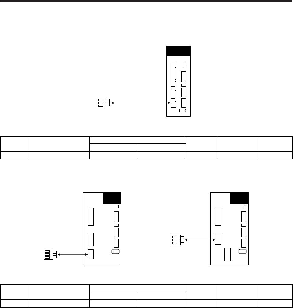
4. CONNECTION OF SERVO AMPLIFIER AND SERVO MOTOR
4 - 21
(1) Connector details
(a) Connector A
CNP3
Servo amplifier
Table 4.1 Connector and applicable wire
Connector Receptacle assembly Applicable wire Stripped
length [mm] Open tool Manufacturer
Wire size Insulator OD
CNP3 03JFAT-SAXGDK-H7.5 AWG 18 to 14 3.9 mm or less 9 J-FAT-OT JST
(b) Connector B
MR-J4-200_(-RJ_)
Servo amplifier
CNP3
CNP3
MR-J4-350_(-RJ_)
Servo amplifier
Table 4.2 Connector and applicable wire
Connector Receptacle assembly Applicable wire Stripped
length [mm] Open tool Manufacturer
Wire size Insulator OD
CNP3 03JFAT-SAXGFK-XL AWG 16 to 10 4.7 mm or less 11.5 J-FAT-OT-EXL JST
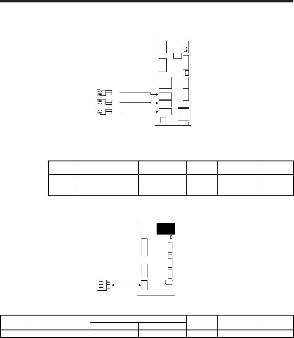
4. CONNECTION OF SERVO AMPLIFIER AND SERVO MOTOR
4 - 22
(c) Connector C
MR-J4W_
Servo amplifier
CNP3A
CNP3B
CNP3C (Note)
Note. This figure shows the MR-J4 3-axis servo amplifier.
Table 4.3 Connector and applicable wire
Connector Receptacle assembly Applicable wire size Stripped
length [mm] Open tool Manufacturer
CNP3A
CNP3B
CNP3C
04JFAT-SAGG-G-KK AWG 18 to 14 9 J-FAT-OT-EXL JST
(d) Connector D
Servo amplifie
r
CNP3
Table 4.4 Connector and applicable wire
Connector Receptacle assembly Applicable wire size Stripped
length [mm] Open tool Manufacturer
Wire size Insulator OD
CNP3 03JFAT-SAXGDK-HT10.5 AWG 16 to 14 3.9 mm or less 10 J-FAT-OT-XL JST
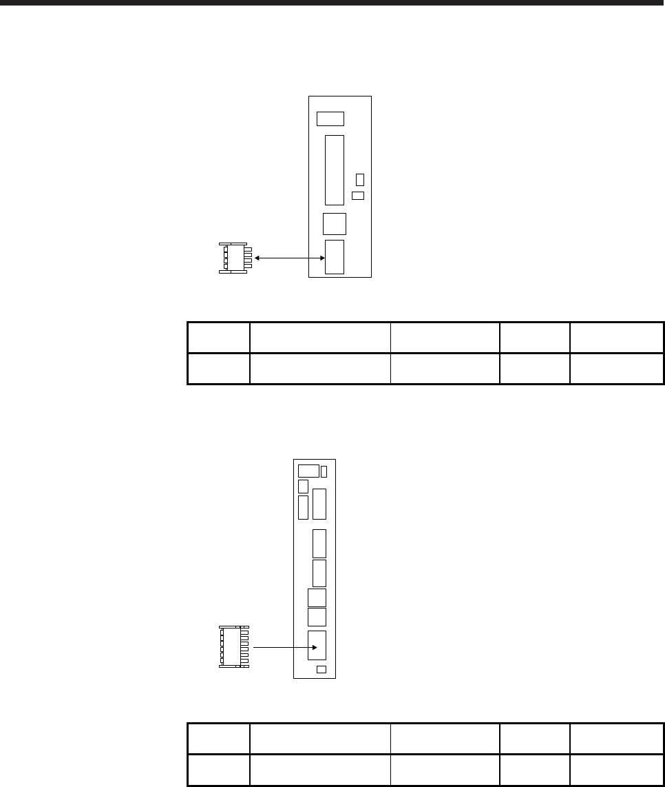
4. CONNECTION OF SERVO AMPLIFIER AND SERVO MOTOR
4 - 23
(e) Connector E
CNP1
MR-J4-03A6(-RJ)
servo amplifier
Table 4.5 Connector and applicable wire
Connector Receptacle assembly Applicable wire size Stripped
length [mm] Manufacturer
CNP1 DFMC 1,5/ 4-ST-3,5-LR
or equivalent AWG 24 to 16 10 Phoenix Contact
(f) Connector F
CNP1
MR-J4W2-0303B6
servo amplifier
Table 4.6 Connector and applicable wire
Connector Receptacle assembly Applicable wire size Stripped
length [mm] Manufacturer
CNP1 DFMC 1,5/ 6-ST-3,5-LR
or equivalent AWG 24 to 16 10 Phoenix Contact
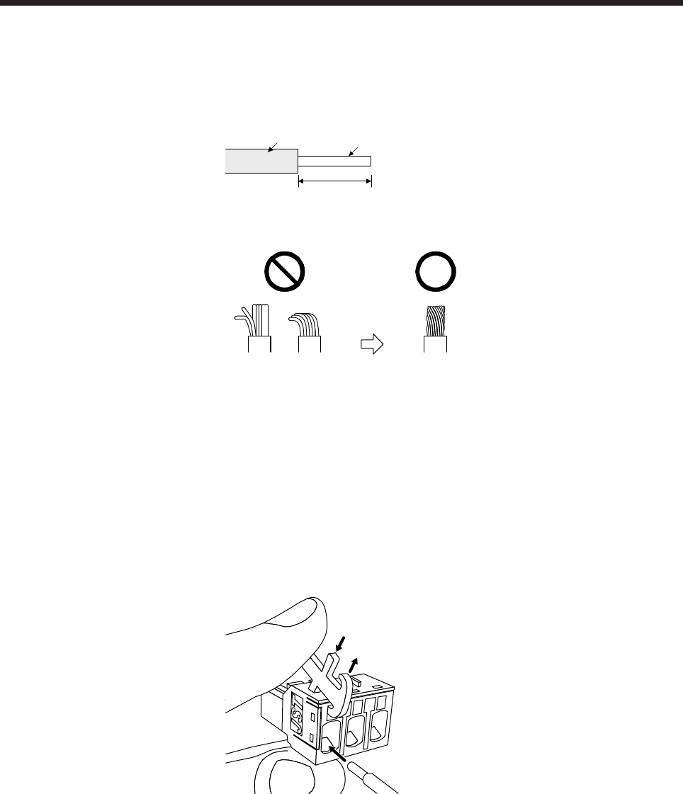
4. CONNECTION OF SERVO AMPLIFIER AND SERVO MOTOR
4 - 24
(2) Cable connection procedure
(a) Cable making
Refer to table 4.1 to 4.4 for stripped length of cable insulator. The appropriate stripped length of
cables depends on their type, etc. Set the length considering their status.
Insulato
r
Core
Stripped length
Twist strands slightly and straighten them as follows.
Loose and bent strands Twist and straighten
the strands.
(b) Inserting wire
1) For connectors requiring an open tool (connector A to connector D)
Insert the open tool as follows and push down it to open the spring. While the open tool is pushed
down, insert the stripped wire into the wire insertion hole. Check the insertion depth so that the
cable insulator does not get caught by the spring.
Release the open tool to fix the wire. Pull the wire lightly to confirm that the wire is surely
connected.
The following shows a connection example of the 03JFAT-SAXGFK-XL.
1) Push down the open tool.
3) Release the open tool to fix the wire.
2) Insert the wire.
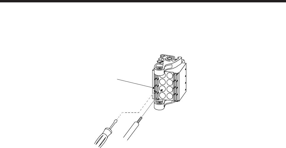
4. CONNECTION OF SERVO AMPLIFIER AND SERVO MOTOR
4 - 25
2) For connectors not requiring an open tool (connector E and connector F)
When using solid wire, insert the wire to the end. When using stranded wire, insert the wire to the
end while pushing the release button with a small flat head screwdriver, etc.
The following shows a connection example of connecting stranded wire to the CNP1 connector.
Release button
Stranded wire

4. CONNECTION OF SERVO AMPLIFIER AND SERVO MOTOR
4 - 26
MEMO
5. WIRING OPTION
5 - 1
5. WIRING OPTION
WARNING
Before connecting any option, turn off the power and wait for 15 minutes or more
(20 minutes or more for converter unit and drive unit) until the charge lamp turns
off. Then, confirm that the voltage between P+ and N- (L+ and L- for converter
unit and drive unit) is safe with a voltage tester and others. Otherwise, an electric
shock may occur. In addition, when confirming whether the charge lamp is off or
not, always confirm it from the front of the servo amplifier (converter unit).
CAUTION
Use specified options. Otherwise, it may cause a malfunction or fire.
MR-J3SCNS(A) and MR-ENCNS2(A) connector sets are packed with a plug and
contacts. Using contacts for other plugs may damage the connector. Be sure to
use the enclosed contacts.
POINT
We recommend using HIV wires to wire the servo motors, options, and
peripheral equipment. Therefore, recommended wire sizes may different from
those of the used wires for the previous servo motors.
When you use a drive unit, "servo amplifier" explained above will be "drive unit".
5.1 Cable/connector sets
POINT
The IP rating indicated is the cable's or connector's protection against ingress of
dust and water when the cable or connector is connected to a servo motor. If the
IP rating of the cable, connector and servo motor vary, the overall IP rating
depends on the lowest IP rating of all components.
Please purchase the cable and connector options indicated in this section for the servo motor.
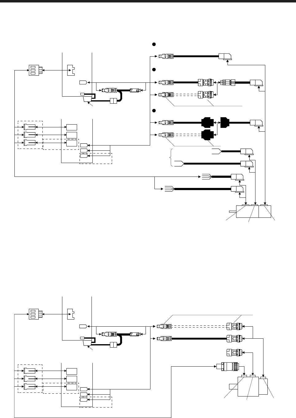
5. WIRING OPTION
5 - 2
5.1.1 Combinations of cable/connector sets
(1) HG-MR series/HG-KR series servo motor
Direct connection (cable length 10 m or less, IP65)
13) 14) 15) 16)
Junction connection (cable length more than 10 m, IP20)
19) 20)
21)
17) 18)
1) 2) 3) 4)
5) 6)
11) 12)
7) 8) 9) 10)
To 24 V DC
power supply for
electromagnetic
brake
Encoder
connector
Electromagnetic
brake connector
Power supply
connector
24) 25)
26)
22) 23)
Junction connection (cable length more than 10 m, IP65)
CNP3A
CNP3B
CNP3C CN2B
CN2A
(Note 2)
(Note 3)
CNP3
(Note 1)
CN2C
(Note 2)
or
MR-J4 multi-axis
servo amplifier
MR-J4 1-axis
servo amplifier
CN2
42)
CN4
MR-BAT6V1BJ
Note 1. Connectors for 3.5 kW or less. For 5 kW or more, it is a terminal block.
2. This connection is for the MR-J4 3-axis servo amplifier.
3. Refer to Appendix 7 for the crimp connector for CNP3_.
(2) HG-SR series/HG-JR53(4) to HG-JR903(4)/HG-JR701M(4) to HG-JR15K1M(4)/HG-JR601(4) to
HG-JR12K1(4)/HG-RR series/HG-UR series servo motor
Encoder
connector
Electromagnetic
brake connector
Power supply
connector
27) 28) 29) 37) 38)
24) 25) 40)
30) 31) 32) 33) 39)
26) 34) 35) 36) 41)
CNP3A
CNP3B
CNP3C CN2B
CN2A
(Note 2)
CNP3
CN2
(Note 1)
CN2C
(Note 2)(Note 3)
or
MR-J4 multi-axis
servo amplifier
MR-J4 1-axis
servo amplifier
42)
CN4
MR-BAT6V1BJ
Note 1. Connectors for 3.5 kW or less. For 5 kW or more, it is a terminal block.
2. This connection is for the MR-J4 3-axis servo amplifier.
3. Refer to Appendix 7 for the crimp connector for CNP3_.
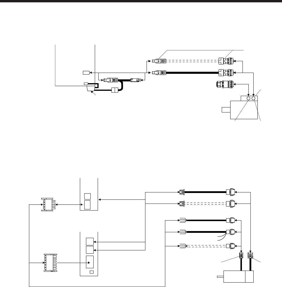
5. WIRING OPTION
5 - 3
(3) HG-JR22K1M(4) to HG-JR37K1M(4)/HG-JR45K1M4/HG-JR55K1M4/HG-JR15K1(4) to HG-JR37K1(4)
servo motor
Servo amplifier
CN2
Encoder
connector
Terminal box
Cooling fan
connector
40) (Note)
43)
41)
42)
CN4
MR-BAT6V1BJ
Note. MR-ENECBL_M-H cannot be used.
(4) HG-AK series servo motor
44)
CN2B
CN2A
CN2
CNP1
CNP1
or
MR-J4W2-0303B6
servo amplifier
MR-J4-03A6(-RJ)
servo amplifier
HG-AK servo motor
Encoder
connector
Power
connector
45) 46)
47)
48)
49) 50)
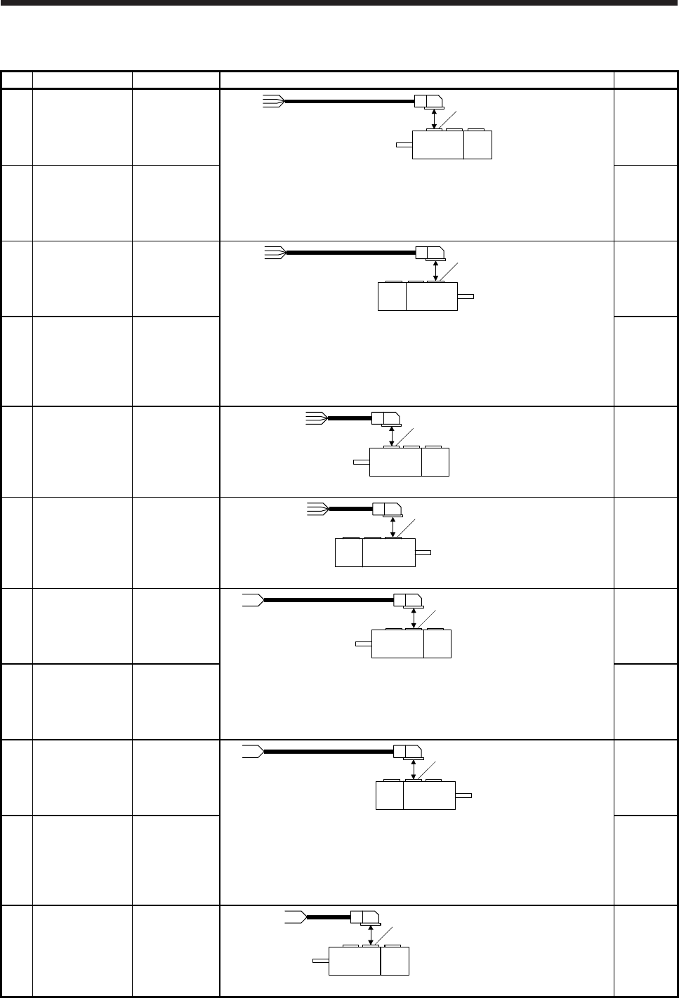
5. WIRING OPTION
5 - 4
5.1.2 Cable and connector list
No. Name Model Description Remark
1) Servo motor
power cable
MR-
PWS1CBL_M-
A1-L (Note 1, 2)
Cable length:
2/5/10 m
Power supply connector
HG-MR series
HG-KR series
Refer to section 5.3 for details.
IP65
Load-side
lead
2) Servo motor
power cable
MR-
PWS1CBL_M-
A1-H (Note 1)
Cable length:
2/5/10 m
IP65
Load-side
lead
Long
bending life
3) Servo motor
power cable
MR-
PWS1CBL_M-
A2-L (Note 1, 2)
Cable length:
2/5/10 m
Power supply connector
HG-MR series
HG-KR series
Refer to section 5.3 for details.
IP65
Opposite to
load-side
lead
4) Servo motor
power cable
MR-
PWS1CBL_M-
A2-H (Note 1)
Cable length:
2/5/10 m
IP65
Opposite to
load-side
lead
Long
bending life
5) Servo motor
power cable
MR-
PWS2CBL03M
-A1-L (Note 1)
Cable length:
0.3 m
Power supply connector
HG-MR series
HG-KR series
Refer to section 5.3 for details.
IP55
Load-side
lead
6) Servo motor
power cable
MR-
PWS2CBL03M
-A2-L (Note 1)
Cable length:
0.3 m
Power supply connector
HG-MR series
HG-KR series
Refer to section 5.3 for details.
IP55
Opposite to
load-side
lead
7) Electromagnetic
brake cable
MR-
BKS1CBL_M-
A1-L
Cable length:
2/5/10 m
Electromagnetic brake connector
HG-MR series
HG-KR series
Refer to section 5.5 for details.
IP65
Load-side
lead
8) Electromagnetic
brake cable
MR-
BKS1CBL_M-
A1-H
Cable length:
2/5/10 m
IP65
Load-side
lead
Long
bending life
9) Electromagnetic
brake cable
MR-
BKS1CBL_M-
A2-L
Cable length:
2/5/10 m
Electromagnetic brake connector
HG-MR series
HG-KR series
Refer to section 5.5 for details.
IP65
Opposite to
load-side
lead
10) Electromagnetic
brake cable
MR-
BKS1CBL_M-
A2-H
Cable length:
2/5/10 m
IP65
Opposite to
load-side
lead
Long
bending life
11) Electromagnetic
brake cable
MR-
BKS2CBL03M-
A1-L
Cable length:
0.3 m
Electromagnetic brake connecto
r
HG-MR series
HG-KR series
Refer to section 5.5 for details.
IP55
Load-side
lead
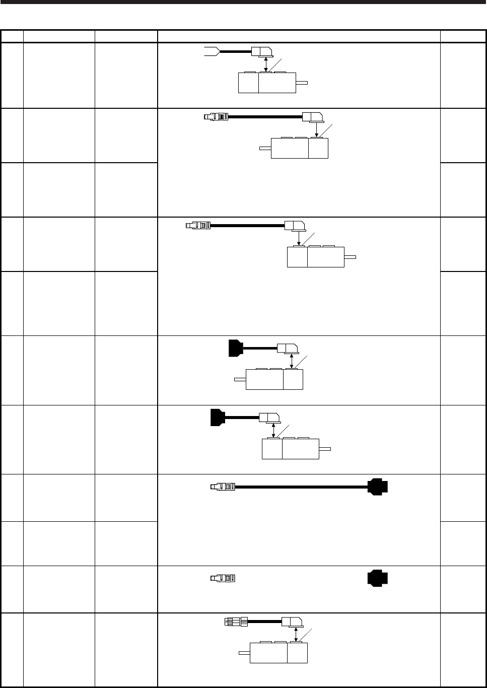
5. WIRING OPTION
5 - 5
No. Name Model Description Remark
12) Electromagnetic
brake cable
MR-
BKS2CBL03M-
A2-L
Cable length:
0.3 m
Electromagnetic brake connector
HG-MR series
HG-KR series
Refer to section 5.5 for details.
IP55
Opposite
to load-
side lead
13) Encoder cable MR-
J3ENCBL_M-
A1-L (Note 1)
Cable length:
2/5/10 m
Encoder connecto
r
HG-MR series
HG-KR series
Refer to section 5.2 (1) for details.
IP65
Load-side
lead
14) Encoder cable MR-
J3ENCBL_M-
A1-H (Note 1)
Cable length:
2/5/10 m
IP65
Load-side
lead
Long
bending life
15) Encoder cable MR-
J3ENCBL_M-
A2-L (Note 1)
Cable length:
2/5/10 m
Encoder connector
HG-MR series
HG-KR series
Refer to section 5.2 (1) for details.
IP65
Opposite
to load-
side lead
16) Encoder cable MR-
J3ENCBL_M-
A2-H (Note 1)
Cable length:
2/5/10 m
IP65
Opposite
to load-
side lead
Long
bending life
17) Encoder cable MR-
J3JCBL03M-
A1-L (Note 1)
Cable length:
0.3 m
Encoder connector
HG-MR series
HG-KR series
Refer to section 5.2 (3) for details.
IP20
Load-side
lead
18) Encoder cable MR-
J3JCBL03M-
A2-L (Note 1)
Cable length:
0.3 m
Encoder connector
HG-MR series
HG-KR series
Refer to section 5.2 (3) for details.
IP20
Opposite to
load-side
lead
19) Encoder cable MR-EKCBL_M-
L
Cable length:
20/30 m
HG-MR/HG-KR series
Refer to section 5.2 (2) for details.
IP20
20) Encoder cable MR-EKCBL_M-
H
Cable length:
20/30/40/50 m
IP20
Long
bending life
21) Encoder
connector set
MR-ECNM
HG-MR/HG-KR series
Refer to section 5.2 (2) for details.
IP20
22) Encoder cable MR-
J3JSCBL03M-
A1-L (Note 1)
Cable length:
0.3 m
Encoder connector
HG-MR series
HG-KR series
Refer to section 5.2 (4) for details.
IP65
Load-side
lead
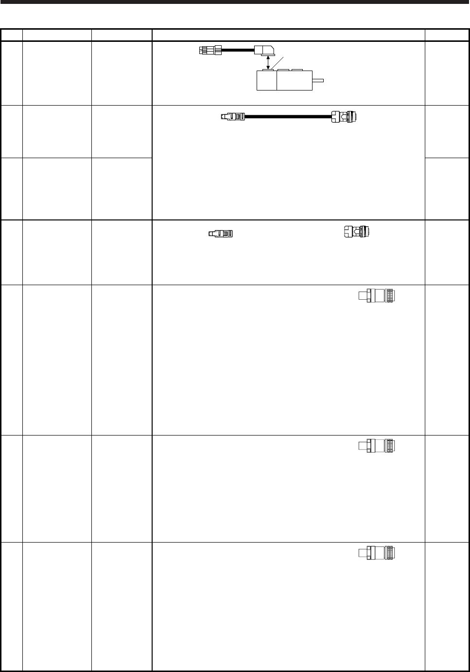
5. WIRING OPTION
5 - 6
No. Name Model Description Remark
23) Encoder cable MR-
J3JSCBL03M-
A2-L (Note 1)
Cable length:
0.3 m
Encoder connector
HG-MR series
HG-KR series
Refer to section 5.2 (4) for details.
IP65
Load-side
lead
24) Encoder cable MR-
J3ENSCBL_M-
L (Note 1)
Cable length:
2/5/10/20/30 m
HG-KR/HG-MR/HG-SR/HG-RR/HG-UR series/
HG-JR53(4)/HG-JR73(4)/HG-JR103(4)/HG-JR153(4)/HG-JR203(4)/
HG-JR353(4)/HG-JR503(4)/HG-JR703(4)/HG-JR903(4)
Refer to section 5.2 (5) for details.
IP67
Standard
bending
life
25) Encoder cable MR-
J3ENSCBL_M-
H (Note 1)
Cable length:
2/5/10/20/30/40
/50 m
IP67
Long
bending life
26) Encoder
connector set
MR-J3SCNS
(Note 1) IP67
HG-KR/HG-MR/HG-SR/HG-RR/HG-UR series/
HG-JR53(4)/HG-JR73(4)/HG-JR103(4)/HG-JR153(4)/HG-JR203(4)/
HG-JR353(4)/HG-JR503(4)/HG-JR703(4)/HG-JR903(4)
Refer to section 5.2 (5) for details.
27) Power connector
set
MR-PWCNS4 Plug: CE05-6A18-10SD-D-BSS
Cable clamp: CE3057-10A-1-D
(DDK)
Applicable cable
Applicable wire size: 2 mm2 (AWG 14) to
3.5 mm2 (AWG 12)
Cable OD: 10.5 mm to 14.1 mm
HG-SR51
HG-SR81
HG-SR52(4)
HG-SR102(4)
HG-SR152(4)
HG-JR53(4)
HG-JR73(4)
HG-JR103(4)
HG-JR153(4)
HG-JR203(4)
HG-JR3534
HG-JR5034
IP67
EN
compliant
28) Power connector
set
MR-PWCNS5 Plug: CE05-6A22-22SD-D-BSS
Cable clamp: CE3057-12A-1-D
(DDK)
Applicable cable
Applicable wire size: 5.5 mm2 (AWG 10) to
8 mm2 (AWG 8)
Cable OD: 12.5 mm to 16 mm
HG-SR121
HG-SR201
HG-SR301
HG-SR202(4)
HG-SR352(4)
HG-SR502(4)
HG-JR353
HG-JR503
IP67
EN
compliant
29) Power connector
set
MR-PWCNS3 Plug: CE05-6A32-17SD-D-BSS
Cable clamp: CE3057-20A-1-D
(DDK)
Applicable cable
Applicable wire size: 14 mm2 (AWG 6) to
22 mm2 (AWG 4)
Cable OD: 22 mm to 23.8 mm
HG-SR421
HG-SR702(4)
HG-JR703(4)
HG-JR903(4)
HG-JR701M(4)
HG-JR11K1M(4)
HG-JR15K1M(4)
HG-JR601(4)
HG-JR801(4)
HG-JR12K1(4)
IP67
EN
compliant
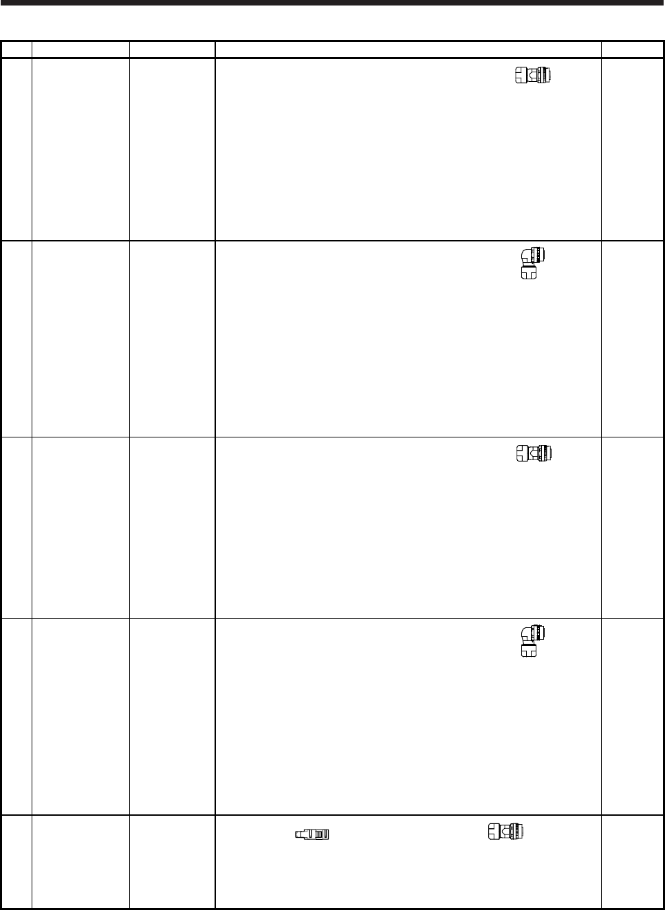
5. WIRING OPTION
5 - 7
No. Name Model Description Remark
30) Electromagnetic
brake connector
set
MR-BKCNS1
(Note 1)
Straight plug: CMV1-SP2S-L
Socket contact: CMV1-#22BSC-S2-100
(DDK)
HG-SR series
HG-JR53(4)
HG-JR73(4)
HG-JR103(4)
HG-JR153(4)
HG-JR203(4)
HG-JR353(4)
HG-JR503(4)
HG-JR703(4)
HG-JR903(4)
IP67
31) Electromagnetic
brake connector
set
MR-BKCNS1A
(Note 1)
Angle plug: CMV1-AP2S-L
Socket contact: CMV1-#22BSC-S2-100
(DDK)
HG-SR series
HG-JR53(4)
HG-JR73(4)
HG-JR103(4)
HG-JR153(4)
HG-JR203(4)
HG-JR353(4)
HG-JR503(4)
HG-JR703(4)
HG-JR903(4)
IP67
32) Electromagnetic
brake connector
set
MR-BKCNS2 Straight plug: CMV1S-SP2S-L
Socket contact: CMV1-#22BSC-S2-100
(DDK)
HG-SR series
HG-JR53(4)
HG-JR73(4)
HG-JR103(4)
HG-JR153(4)
HG-JR203(4)
HG-JR353(4)
HG-JR503(4)
HG-JR703(4)
HG-JR903(4)
IP67
33) Electromagnetic
brake connector
set
MR-BKCNS2A Angle plug: CMV1S-AP2S-L
Socket contact: CMV1-#22BSC-S2-100
(DDK)
HG-SR series
HG-JR53(4)
HG-JR73(4)
HG-JR103(4)
HG-JR153(4)
HG-JR203(4)
HG-JR353(4)
HG-JR503(4)
HG-JR703(4)
HG-JR903(4)
IP67
34) Encoder
Connector set
MR-ENCNS2 IP67
HG-KR/HG-MR/HG-SR/HG-RR/HG-UR series/
HG-JR53(4)/HG-JR73(4)/HG-JR103(4)/HG-JR153(4)/HG-JR203(4)/
HG-JR353(4)/HG-JR503(4)/HG-JR703(4)/HG-JR903(4)
Refer to section 5.2 (5) for details.
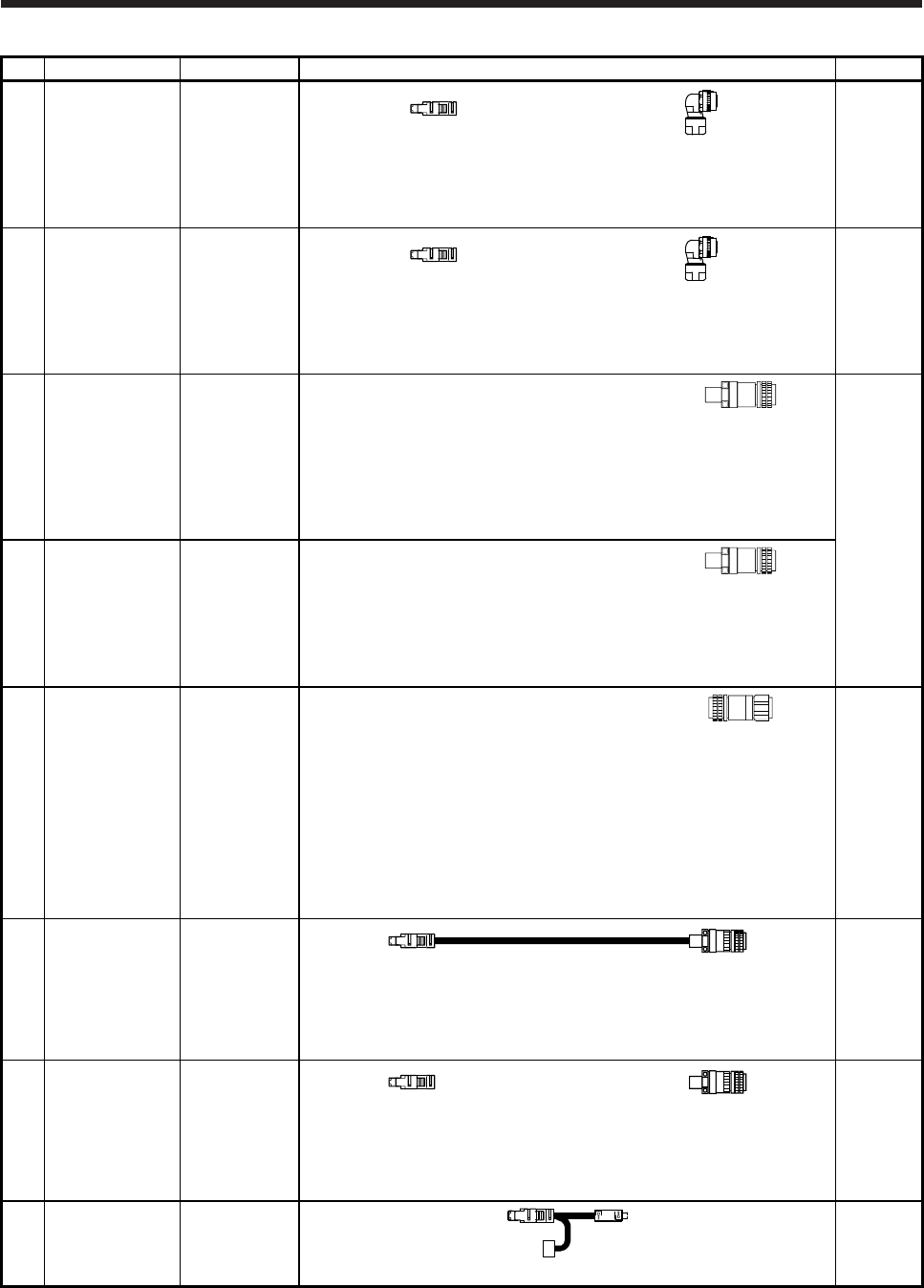
5. WIRING OPTION
5 - 8
No. Name Model Description Remark
35) Encoder
Connector set
MR-J3SCNSA
(Note 1)
IP67
HG-KR/HG-MR/HG-SR/HG-RR/HG-UR series/
HG-JR53(4)/HG-JR73(4)/HG-JR103(4)/HG-JR153(4)/HG-JR203(4)/
HG-JR353(4)/HG-JR503(4)/HG-JR703(4)/HG-JR903(4)
Refer to section 5.2 (5) for details.
36) Encoder
Connector set
MR-ENCNS2A
IP67
HG-KR/HG-MR/HG-SR/HG-RR/HG-UR series/
HG-JR53(4)/HG-JR73(4)/HG-JR103(4)/HG-JR153(4)/HG-JR203(4)/
HG-JR353(4)/HG-JR503(4)/HG-JR703(4)/HG-JR903(4)
Refer to section 5.2 (5) for details.
37) Power connector
set
MR-PWCNS1 Plug: CE05-6A22-23SD-D-BSS
Cable clamp: CE3057-12A-2-D
(DDK)
Applicable cable
Applicable wire size: 2 mm2 to 3.5 mm2
(AWG 14 to 12)
Cable OD: 9.5 mm to 13 mm
HG-RR103
HG-RR153
HG-RR203
HG-UR72
HG-UR152
IP65
EN
compliant
38) Power connector
set
MR-PWCNS2 Plug: CE05-6A24-10SD-D-BSS
Cable clamp: CE3057-16A-2-D
(DDK)
Applicable cable
Applicable wire size: 5.5 mm2 to 8 mm2
(AWG 10 to 8)
Cable OD: 13 mm to 15.5 mm
HG-RR353
HG-RR503
HG-UR202
HG-UR352
HG-UR502
39) Electromagnetic
brake connector
set
MR-BKCN Plug: D/MS3106A10SL-4S(D190) (DDK)
Cable clamp: YSO10-5-8 (Daiwa Dengyo)
Applicable cable
Applicable wire size: 0.3 mm2 to 1.25 mm2
(AWG 22 to 16)
Cable OD: 5 mm to 8.3 mm
HG-UR202
HG-UR352
HG-UR502
HG-JR701M(4)
HG-JR11K1M(4)
HG-JR15K1M(4)
HG-JR601(4)
HG-JR801(4)
HG-JR12K1(4)
IP65
EN
compliant
40) Encoder cable MR-ENECBL_
M-H-MTH
HG-JR701M(4)/HG-JR11K1M(4)/HG-JR15K1M(4)/HG-JR22K1M(4)/
HG-JR30K1M(4)/HG-JR37K1M(4)/HG-JR45K1M4/HG-JR55K1M4/
HG-JR601(4)/HG-JR801(4)/HG-JR12K1(4)/HG-JR15K1(4)/HG-JR20K1(4)/
HG-JR25K1(4)/HG-JR30K1(4)/HG-JR37K1(4)
Refer to section 5.2 (6) for details.
IP67
Long
bending
life
41) Encoder
connector set
MR-ENECNS
HG-JR701M(4)/HG-JR11K1M(4)/HG-JR15K1M(4)/HG-JR22K1M(4)/
HG-JR30K1M(4)/HG-JR37K1M(4)/HG-JR45K1M4/HG-JR55K1M4/
HG-JR601(4)/HG-JR801(4)/HG-JR12K1(4)/HG-JR15K1(4)/HG-JR20K1(4)/
HG-JR25K1(4)/HG-JR30K1(4)/HG-JR37K1(4)
Refer to section 5.2 (6) for details.
IP67
42) Junction battery
cable
MR-
BT6VCBL03M
Refer to section 5.2 (7) for details.
Only for
MR-
BAT6V1BJ
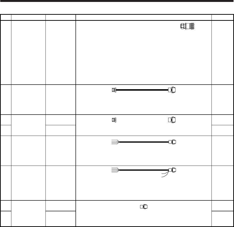
5. WIRING OPTION
5 - 9
No. Name Model Description Remark
43) Cooling fan power
connector set
MR-PWCNF Plug: CE05-6A14S-2SD-D (DDK)
Cable clamp: YSO14-9 to 11 (Daiwa Dengyo)
Applicable cable
Applicable wire size: 0.3 mm2 to 1.25 mm2
(AWG 22 to 16)
Cable OD: 8.3 mm to 11.3 mm
HG-JR22K1M(4)
HG-JR30K1M(4)
HG-JR37K1M(4)
HG-JR45K1M4
HG-JR55K1M4
HG-JR15K1(4)
HG-JR20K1(4)
HG-JR25K1(4)
HG-JR30K1(4)
HG-JR37K1(4)
IP67
EN
compliant
44) Encoder cable MR-
J3W03ENCBL
_M-A-H
Cable length:
1/2/5/10/20/30
m
Refer to section 5.2 (8) for details.
Long
bending life
45) Encoder
connector set
MR-
J3W03CN2-2P
Refer to section 5.2 (8) for details.
Quantity: 2
46) MR-
J3W03CN2-20P
Quantity:
20
47) Servo motor
power cable
MR-
J4W03PWCBL
_M-H
Cable length:
1/2/5/10/20/30
m
Refer to section 5.4 for details.
Long
bending life
48) Servo motor
power cable
MR-
J4W03PWBRC
BL_M-H
Cable length:
1/2/5/10/20/30
m
Refer to section 5.4 for details.
Long
bending life
Servo
motor with
an electro-
magnetic
brake
49) Servo motor
power connector
set
MR-
J4W03CNP2-2P
Refer to section 5.4 for details.
Quantity: 2
50) MR-
J4W03CNP2-
20P
Quantity:
20
Note 1. The cable and the connector set may contain different connectors but still usable.
2. For servo motor power cable, MR-PWS3CBL_M-A_-L using shielded cable is also available. For details, contact your local
sales office.
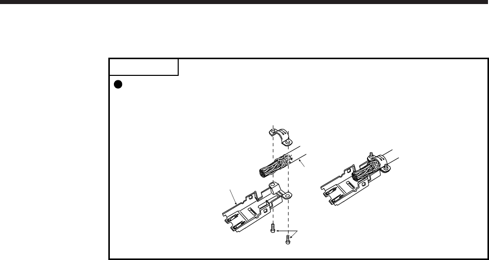
5. WIRING OPTION
5 - 10
5.2 Encoder cable/connector sets
POINT
For CN2, CN2A, CN2B, and CN2C side connectors, securely connect the
shielded external conductor of the cable to the ground plate and fix it to the
connector shell.
Screw
Cable
Ground plate
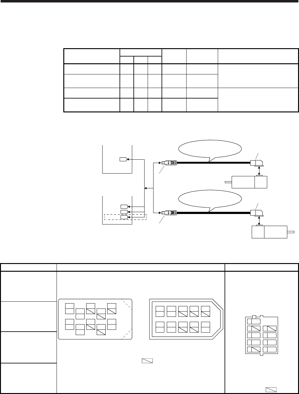
5. WIRING OPTION
5 - 11
(1) MR-J3ENCBL_M-_-_
These cables are encoder cables for the HG-MR/HG-KR series servo motors. The numbers in the cable
length field of the table indicate the symbol filling the underline "_" in the cable model.
Cable model Cable length IP rating Bending life Application
2 m 5 m 10 m
MR-J3ENCBL_M-A1-L 2 5 10 IP65 Standard
Load-side lead for HG-MR/HG-KR
MR-J3ENCBL_M-A1-H 2 5 10 IP65 Long
bending life
MR-J3ENCBL_M-A2-L 2 5 10 IP65 Standard
Opposite to load-side lead for HG-
MR/HG-KR
MR-J3ENCBL_M-A2-H 2 5 10 IP65 Long
bending life
(a) Connection of servo amplifier and servo motor
2)
1)
Servo moto
r
HG-MR
HG-KR
MR-J3ENCBL_M-A2-L
MR-J3ENCBL_M-A2-H
2)
1)
Servo moto
r
HG-MR
HG-KR
MR-J3ENCBL_M-A1-L
MR-J3ENCBL_M-A1-H
or
CN2B
CN2A
(Note)
CN2
CN2C
or
MR-J4 multi-axis
servo amplifier
MR-J4 1-axis
servo amplifier
Note. This connection is for the MR-J4 3-axis servo amplifier.
Cable model 1) CN2, CN2A, CN2B, and CN2C side connector 2) Encoder-side connector
MR-J3ENCBL_M-A1-L Receptacle: 36210-0100PL
Shell kit: 36310-3200-008
(3M or equivalent)
Connector set: 54599-1019
(Molex)
Connector: 2174053-1
Crimping tool for ground clip:
1596970-1
Crimping tool for receptacle
contact: 1596847-1
(TE Connectivity)
9SHD
7
5MR
3P5
1
8
6LG
4MRR
2BAT
View seen from wiring side.
(Note)
1
P5 3
MR 79
BAT
4
MRR
2
LG 8610
5
View seen from wiring side. (Note)
or
4
MRR
2
LG 8
6
1
P5 5
10
3
MR 79
BAT
View seen from wiring side. (Note)
MR-J3ENCBL_M-A1-H
MR-J3ENCBL_M-A2-L
Note. Keep open the pins shown with . Especially, pin 10 is provided
for manufacturer adjustment. If it is connected with any other pin, the
servo amplifier cannot operate normally. Referring POINT of section
5.2, securely connect the shielded cable external conductor of the
shielded cable to the ground plate and fix it to the connector shell.
MR-J3ENCBL_M-A2-H
Note. Keep open the pins
shown with .
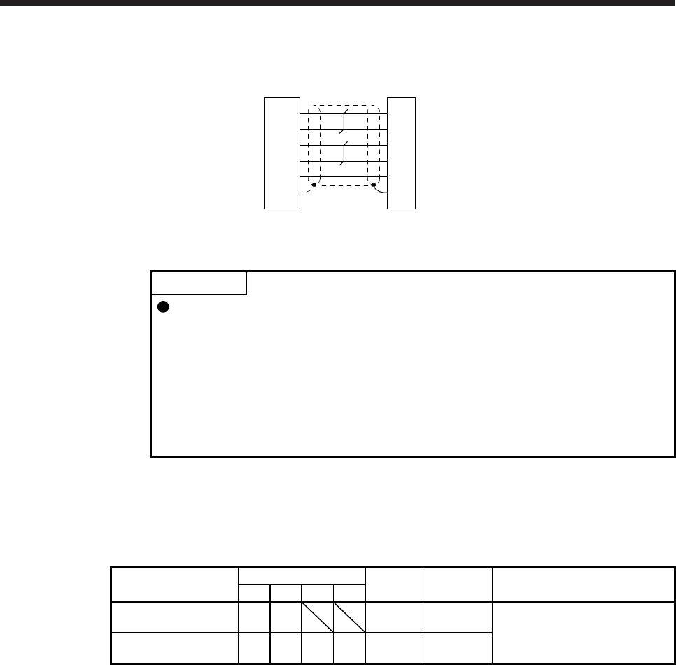
5. WIRING OPTION
5 - 12
(b) Cable internal wiring diagram
P5
LG
1
2
MR
MRR
3
4
2
3
CN2, CN2A, CN2B, and
CN2C side connector Encoder-side
connector
9
SD Plate
5
4
6
9
LG
MR
MRR
SHD
P5
BATBAT
(2) MR-EKCBL_M-_
POINT
The following encoder cables are of four-wire type.
MR-EKCBL30M-L
MR-EKCBL30M-H
MR-EKCBL40M-H
MR-EKCBL50M-H
When using any of these encoder cables, select "four-wire type" referring each
servo amplifier instruction manual.
If the setting is incorrect, [AL. 16] occurs.
The servo amplifier and the servo motor cannot be connected by these cables alone. The servo motor-
side encoder cable (MR-J3JCBL03M-_-L) is required.
The numbers in the cable length field of the table indicate the symbol filling the underline "_" in the cable
model.
Cable model Cable length IP rating Bending life Application
20 m 30 m 40 m 50 m
MR-EKCBL_M-L 20
(Note)
30 IP20 Standard
For HG-MR/HG-KR
Use in combination with MR-
J3JCBL03M-_-L.
MR-EKCBL_M-H 20
(Note)
30
(Note)
40
(Note)
50 IP20 Long
bending life
Note. Four-wire type cable
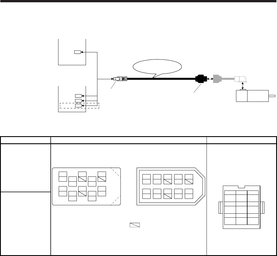
5. WIRING OPTION
5 - 13
(a) Connection of servo amplifier and servo motor
1)
MR-EKCBL_M-L
MR-EKCBL_M-H
2)
CN2B
CN2A
(Note)
CN2
CN2C
or
MR-J4 multi-axis
servo amplifier
MR-J4 1-axis
servo amplifier
Servo motor
HG-MR
HG-KR
MR-J3JCBL03M-A2-L
Cable length: 0.3 m
Note. This connection is for the MR-J4 3-axis servo amplifier.
Cable model 1) CN2, CN2A, CN2B, and CN2C side connector 2) Junction connector
MR-EKCBL_M-L Receptacle: 36210-0100PL
Shell kit: 36310-3200-008
(3M)
Connector set: 54599-1019
(Molex)
Housing: 1-172161-9
Connector pin: 170359-1
Crimping tool: 91529-1
(TE Connectivity or equivalent)
Cable clamp: MTI-0002
(Toa Electric Industrial)
MR
123
MRR BAT
MD
456
MDR
P5
789
LG SHD
View seen from wiring side.
CONT
MRR
LG
P5 MR
BAT
MDR
MD P5 MR BAT
MRR
LG MDR
MD
13 79
428610
5
View seen from wiring side. (Note)
or
4
28
6
15
10
37
9
View seen from wiring side. (Note)
MR-EKCBL_M-H
Note. Keep open the pins shown with . Especially, pin 10 is provided
for manufacturer adjustment. If it is connected with any other pin, the
servo amplifier cannot operate normally. Referring POINT of section
5.2, securely connect the shielded cable external conductor of the
shielded cable to the ground plate and fix it to the connector shell.
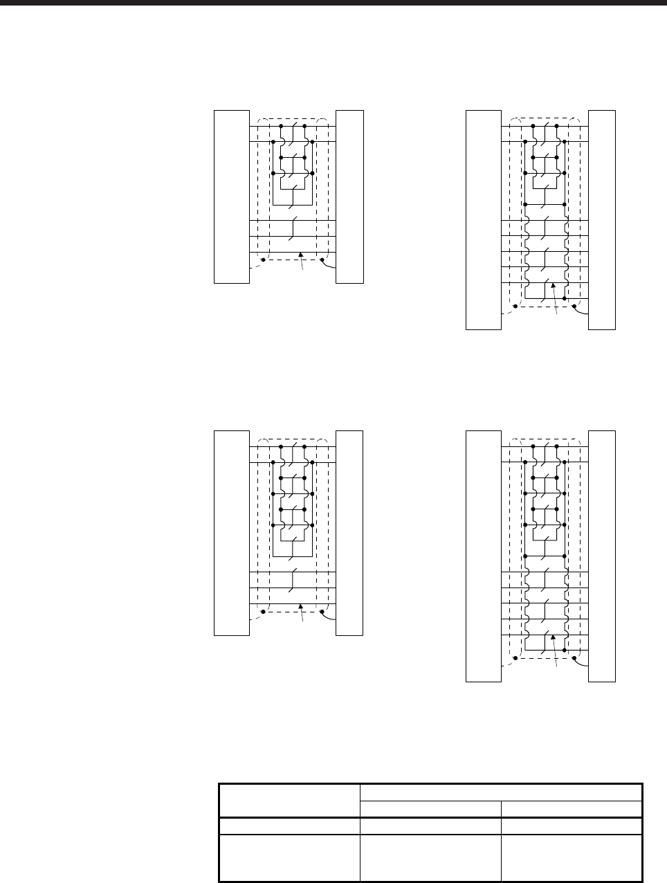
5. WIRING OPTION
5 - 14
(b) Internal wiring diagram
MR-EKCBL20M-L
CN2, CN2A, CN2B, and
CN2C side connector Junction
connector
(Note)
P5
LG
1
2
MR
MRR
3
4
3
7
9
SD Plate
1
2
8
9
LG
MR
MRR
SHD
P5
BATBAT
MR-EKCBL30M-L
(Note)
P5
LG
1
2
MR
MRR
3
4
MDR 8 5
3
7
4
MD 7
9
SD Plate
1
2
8
9
LG
MR
MRR
MDR
MD
SHD
P5
6 CONT
BATBAT
CN2, CN2A, CN2B, and
CN2C side connector Junction
connector
MR-EKCBL20M-H
(Note)
P5
LG
1
2
MR
MRR
3
4
3
7
9
SD Plate
1
2
8
9
LG
MR
MRR
SHD
P5
BATBAT
CN2, CN2A, CN2B, and
CN2C side connector Junction
connector
MR-EKCBL30M-H
MR-EKCBL40M-H
MR-EKCBL50M-H
CN2, CN2A, CN2B, and
CN2C side connector Junction
connector
(Note)
P5
LG
1
2
MR
MRR
3
4
MDR 85
3
7
4
MD 7
9
SD Plate
1
2
8
9
LG
MR
MRR
MDR
MD
SHD
P5
6CONT
BATBAT
Note.
A
lways make connection for use in an absolute position detection system. Wiring is not necessary
for use in an incremental system.
When fabricating the cable, use the wiring diagram corresponding to the length indicated below.
Cable bending life Applicable wiring diagram
Less than 30 m 30 m to 50 m
Standard MR-EKCBL20M-L MR-EKCBL30M-L
Long bending life MR-EKCBL20M-H MR-EKCBL30M-H
MR-EKCBL40M-H
MR-EKCBL50M-H
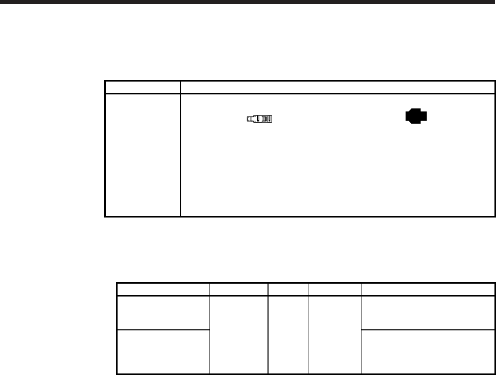
5. WIRING OPTION
5 - 15
(c) When fabricating the encoder cable
When fabricating the cable, prepare the following parts, and fabricate it according to the wiring
diagram in (b). Refer to section 5.6 for the specifications of the cable to use.
Parts Description
Connector set MR-ECNM
CN2, CN2A, CN2B, and CN2C side
connector
Receptacle: 36210-0100PL
Shell kit: 36310-3200-008
(3M)
or
Connector set: 54599-1019
(Molex)
Encoder-side connector
Housing: 1-172161-9
Connector pin: 170359-1
(TE Connectivity or equivalent)
Cable clamp: MTI-0002
(Toa Electric Industrial)
(3) MR-J3JCBL03M-_-L
The servo amplifier and the servo motor cannot be connected by these cables alone. The servo motor-
side encoder cable (MR-EKCBL_M-_) is required.
Cable model Cable length IP rating Bending life Application
MR-J3JCBL03M-A1-L
0.3 m IP20 Standard
Load-side lead for HG-MR/HG-KR
Use in combination with MR-
EKCBL_M-_.
MR-J3JCBL03M-A2-L
Opposite to load-side lead for HG-
MR/HG-KR
Use in combination with MR-
EKCBL_M-_.
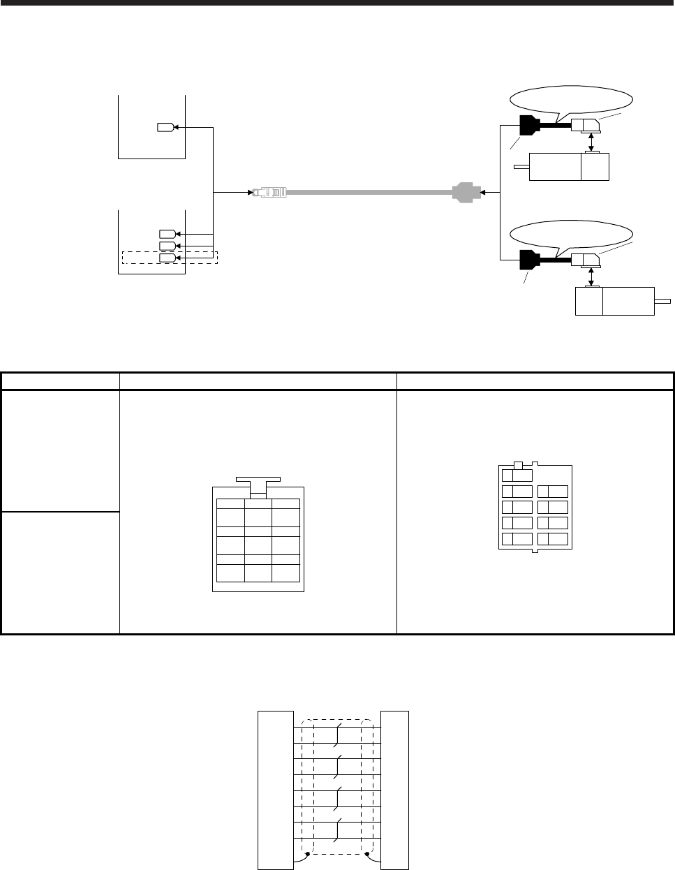
5. WIRING OPTION
5 - 16
(a) Connection of servo amplifier and servo motor
Servo motor
HG-MR
HG-KR
MR-J3JCBL03M-A2-L
MR-EKCBL_M-_
1)
2)
2)
Servo motor
HG-MR
HG-KR
MR-J3JCBL03M-A1-L
1)
or
CN2B
CN2A
(Note)
CN2
CN2C
or
MR-J4 multi-axis
servo amplifier
MR-J4 1-axis
servo amplifier
Note. This connection is for the MR-J4 3-axis servo amplifier.
Cable model 1) Junction connector 2) Encoder-side connector
MR-J3JCBL03M-A1-L Housing: 1-172169-9
Contact: 1473226-1
Cable clamp: 316454-1
Crimping tool: 91529-1
(TE Connectivity)
MR
123
MRRBAT
MD
456
MDR
P5
789
LGSHD
View seen from wiring side.
CONT
Connector: 2174053-1
Crimping tool for ground clip: 1596970-1
Crimping tool for receptacle contact: 1596847-1
(TE Connectivity)
MDR
CONT
MD
9SHD
7
5MR
3P5
1
8
6LG
4MRR
2BAT
View seen from wiring side.
MR-J3JCBL03M-A2-L
(b) Internal wiring diagram
Junction
connector Encoder-side
connector
P5
LG
7
8
MR
MRR
1
2
1
3
6
SHD
5
4
6
9
LG
MR
MRR
SHD
P5
CONTCONT
MD 4 8 MD
MDR 5 7 MDR
BAT 3 2 BAT
9
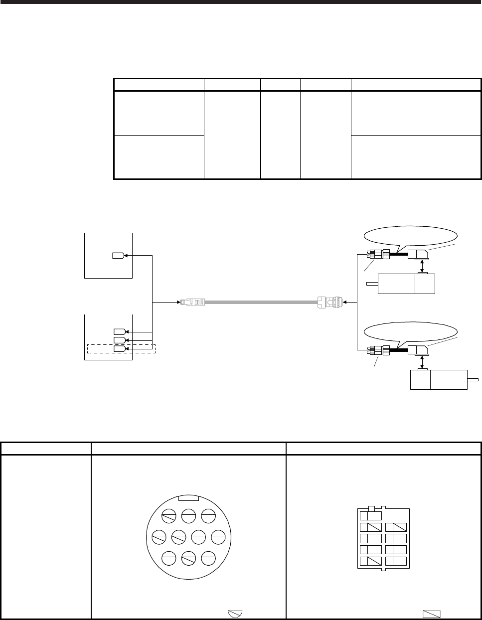
5. WIRING OPTION
5 - 17
(4) MR-J3JSCBL03M-_-L
The servo amplifier and the servo motor cannot be connected by these cables alone. The servo motor-
side encoder cable (MR-J3ENSCBL_M-_) is required.
Cable model Cable length IP rating Bending life Application
MR-J3JSCBL03M-A1-L
0.3 m IP65 Standard
For HG-KR/HG-MR
Load-side lead
Use in combination with MR-
J3ENSCBL_M-_.
MR-J3JSCBL03M-A2-L
For HG-KR/HG-MR
Opposite to load-side lead
Use in combination with MR-
J3ENSCBL_M-_.
(a) Connection of servo amplifier and servo motor
or
Servo motor
HG-MR
HG-KR
MR-J3JSCBL03M-A2-L
1)
2)
Servo motor
HG-MR
HG-KR
MR-J3JSCBL03M-A1-L
1)
2)
(Note 2)
MR-J3ENSCBL_M-_
CN2B
CN2A
(Note 1)
CN2
CN2C
or
MR-J4 multi-axis
servo amplifier
MR-J4 1-axis
servo amplifier
Note 1. This connection is for the MR-J4 3-axis servo amplifier.
2. For details of this cable, refer to (5) in this section.
Cable model 1) Junction connector 2) Encoder-side connector
MR-J3JSCBL03M-A1-L Receptacle: CM10-CR10P-M
(DDK)
Applicable wire size: AWG 20 or less
1
MR
2
MRR
3
5
LG 476
10
SHD
98
P5
BAT
View seen from wiring side. (Note)
Connector: 2174053-1
Crimping tool for ground clip: 1596970-1
Crimping tool for receptacle contact: 1596847-1
(TE Connectivity)
9SHD
7
5MR
3P5
1
8
6LG
4MRR
2BAT
View seen from wiring side. (Note
)
MR-J3JSCBL03M-A2-L
Note. Keep open the pins shown with . Note. Keep open the pins shown with .
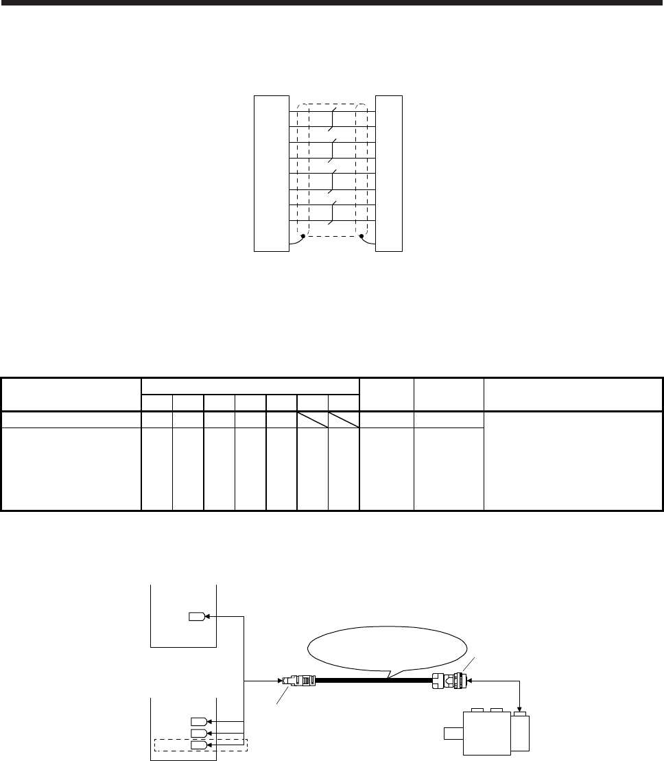
5. WIRING OPTION
5 - 18
(b) Internal wiring diagram
8
5
1
2
1
3
3
5
4
6
9
68
77
42
10
Junction
connector Encoder-side
connector
P5
LG
MR
MRR
SHD
LG
MR
MR
R
SHD
P5
BAT BAT
(5) MR-J3ENSCBL_M-_
These cables are encoder cables for the HG-MR/HG-KR/HG-SR/HG-RR/HG-UR series/HG-
JR53(4)/HGJR73(4)/HG-JR103(4)/HG-JR153(4)/HG-JR203(4)/HG-JR353(4)/HG-JR503(4)/HG-
JR703(4) and HG-JR903(4) servo motors. The numbers in the cable length field of the table indicate the
symbol filling the underline "_" in the cable model.
Cable model Cable length
IP rating Bending life Application
2 m 5 m 10 m 20 m 30 m 40 m 50 m
MR-J3ENSCBL_M-L 2 5 10 20 30 IP67 Standard For HG-MR/HG-KR/HG-SR/
HG-RR/HG-UR series/
HG-JR53(4)/HGJR73(4)/
HG-JR103(4)/HG-JR153(4)/
HG-JR203(4)/HG-JR353(4)/
HG-JR503(4)/HG-JR703(4) and
HG-JR903(4)
MR-J3ENSCBL_M-H 2 5 10 20 30 40 50 IP67 Long
bending life
(a) Connection of servo amplifier and servo motor
1)
2)
MR-J3ENSCBL_M-L
MR-J3ENSCBL_M-H Servo motor
HG-SR
HG-RR
HG-UR
HG-JR53(4) to HG-JR903(4)
CN2B
CN2A
(Note)
CN2
CN2C
or
MR-J4 multi-axis
servo amplifier
MR-J4 1-axis
servo amplifier
Note. This connection is for the MR-J4 3-axis servo amplifier.
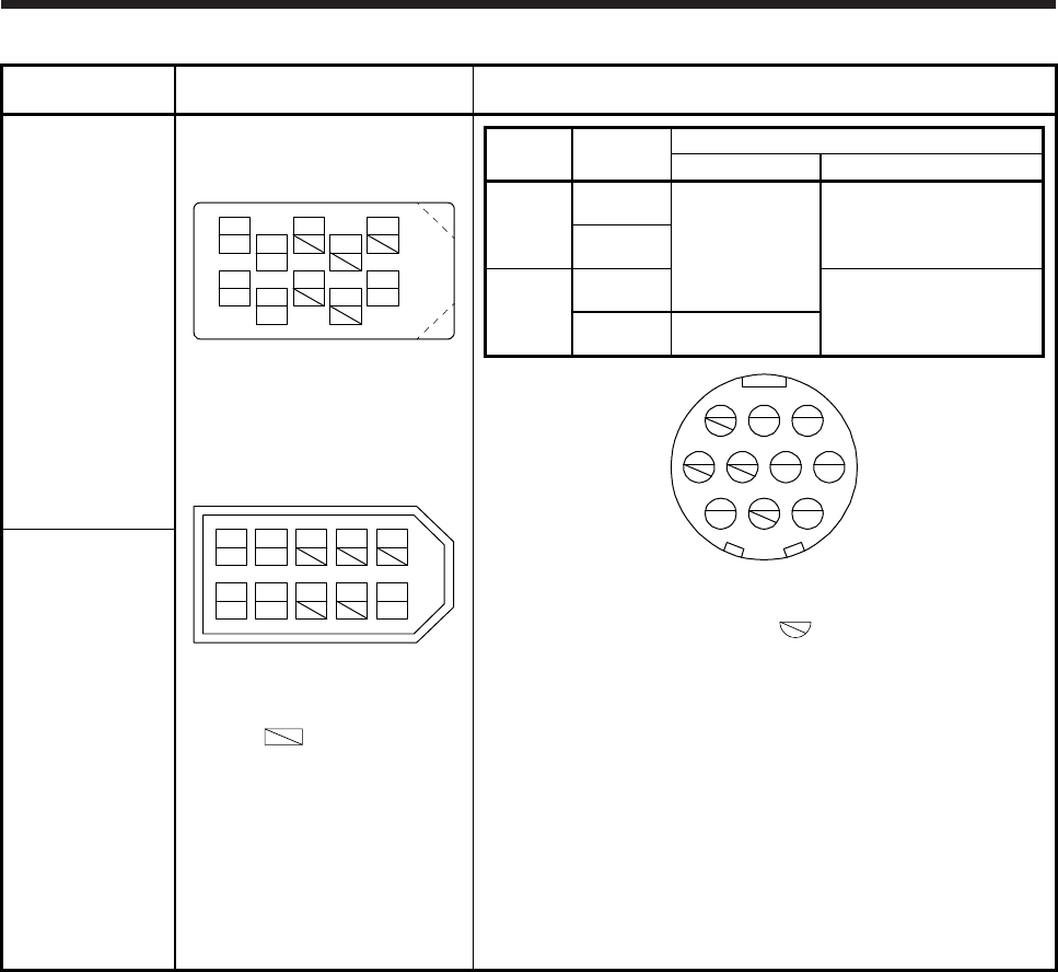
5. WIRING OPTION
5 - 19
Cable model 1) CN2, CN2A, CN2B, and CN2C
side connector 2) Encoder-side connector
MR-J3ENSCBL_M-
L
Receptacle: 36210-0100PL
Shell kit: 36310-3200-008
(3M)
MRR
LG
P5 MR
BAT
4
28
6
15
10
37
9
View seen from wiring side. (Note)
or
Connector set: 54599-1019
(Molex)
P5 MR BAT
MRR
LG
13 79
428610
5
V
iew seen from wiring side. (Note
)
Cable
length Bending life Plug (DDK)
Straight plug Socket contact
10 m or
shorter
Long
bending life
CMV1-SP10S-M1
CMV1-#22ASC-C1-100
Applicable wire size: AWG 24
to 20
Crimping tool:357J-53162T
Standard
20 m or
longer
Long
bending life
CMV1-#22ASC-C2-100
Applicable wire size: AWG 28
to 24
Crimping tool:357J-53163T
Standard CMV1-SP10S-M2
1
MR
2
MRR
3
5
LG 476
10
SHD
98
P5
BAT
View seen from wiring side. (Note)
MR-J3ENSCBL_M-
H
Note. Keep open the pins shown with .
Note. Keep open the pins shown
with . Especially, pin 10
is provided for manufacturer
adjustment. If it is connected
with any other pin, the servo
amplifier cannot operate
normally. Referring POINT of
section 5.2, securely connect
the shielded cable external
conductor of the shielded
cable to the ground plate and
fix it to the connector shell.
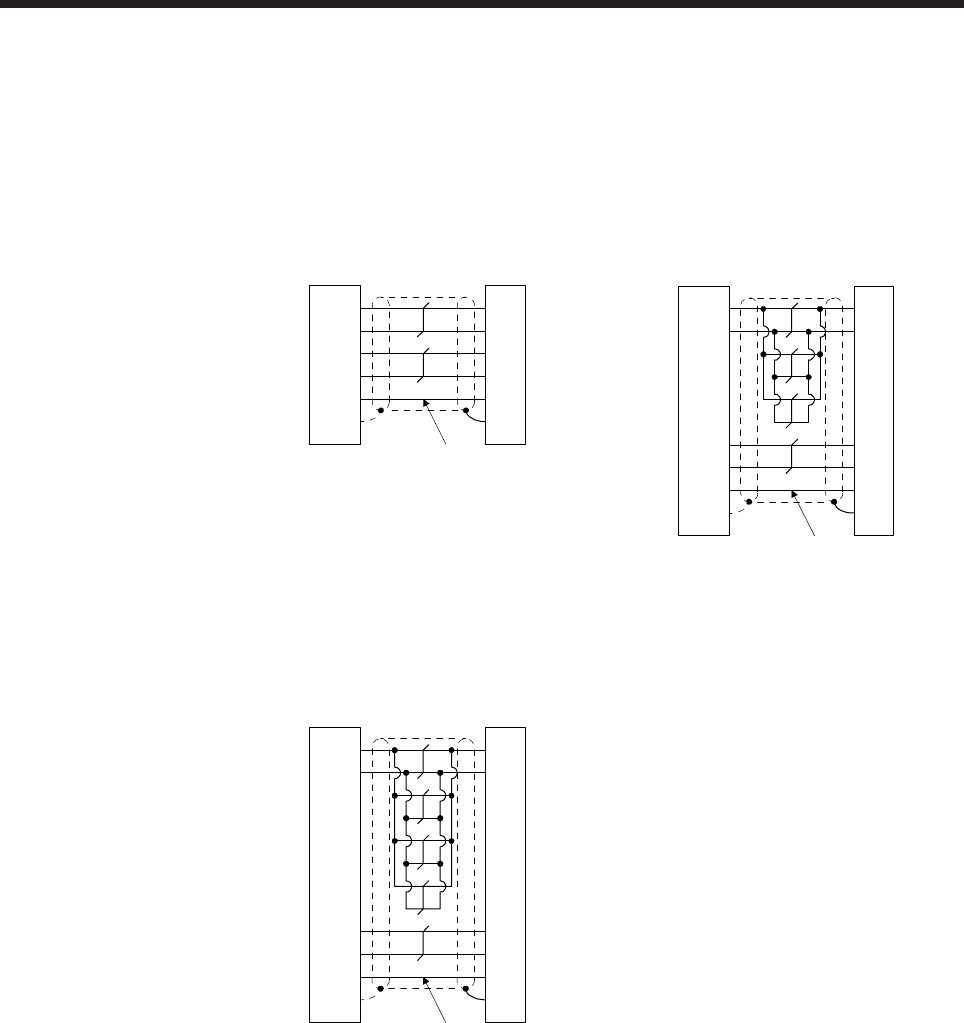
5. WIRING OPTION
5 - 20
(b) Cable internal wiring diagram
MR-J3ENSCBL2M-L
MR-J3ENSCBL5M-L
MR-J3ENSCBL10M-L
MR-J3ENSCBL2M-H
MR-J3ENSCBL5M-H
MR-J3ENSCBL10M-H
MR-J3ENSCBL20M-L
MR-J3ENSCBL30M-L
4
8
1
2
5
10
P5
LG
1
2
MR
MRR
3
4
CN2, CN2A, CN2B, and
CN2C side connector Encoder-side
connector
9
SD Plate
LG
MR
MR
R
SHD
P5
BATBAT
(Note)
4
8
1
2
5
10
CN2, CN2A, CN2B, and
CN2C side connector Encoder-side
connector
(Note)
P5
LG
1
2
MR
MRR
3
4
9
SD Plate
LG
MR
MRR
SHD
P5
BATBAT
MR-J3ENSCBL20M-H
MR-J3ENSCBL30M-H
MR-J3ENSCBL40M-H
MR-J3ENSCBL50M-H
4
8
1
2
5
10
P5
LG
1
2
MR
MRR
3
4
9
SD Plate
LG
MR
MRR
SHD
P5
BATBAT
CN2, CN2A, CN2B, and
CN2C side connector Encoder-side
connector
(Note)
Note.
A
lways make connection for use in an absolute position detection system. Wiring is not necessary
for use in an incremental system.
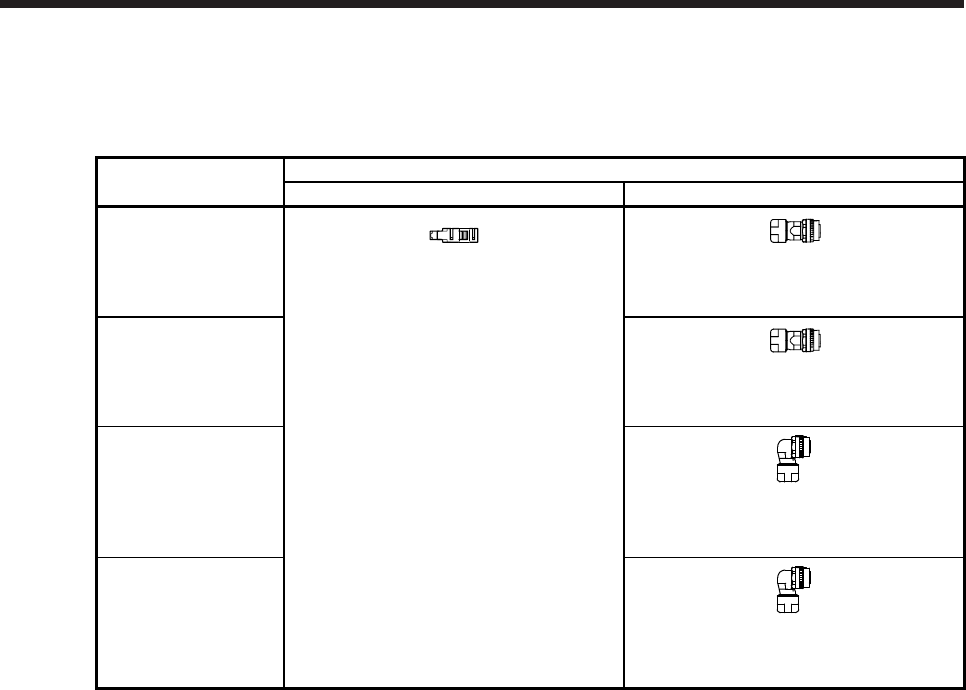
5. WIRING OPTION
5 - 21
(c) When fabricating the encoder cable
When fabricating the cable, prepare the following parts, and fabricate it according to the wiring
diagram in (b). Refer to section 5.5 for the specifications of the used cable.
Parts
(Connector set)
Description
Servo amplifier side connector Encoder-side connector (DDK)
MR-J3SCNS
(one-touch connection
type)
(Note)
Receptacle: 36210-0100PL
Shell kit: 36310-3200-008
(3M)
or
Connector set: 54599-1019
(Molex)
Straight plug: CMV1-SP10S-M2
Socket contact: CMV1-#22ASC-S1-100
Applicable wire size: AWG 20 or less
MR-ENCNS2
(screw type)
(Note)
Straight plug: CMV1S-SP10S-M2
Socket contact: CMV1-#22ASC-S1-100
Applicable wire size: AWG 20 or less
MR-J3SCNSA
(one-touch connection
type)
(Note)
Angle plug: CMV1-AP10S-M2
Socket contact: CMV1-#22ASC-S1-100
Applicable wire size: AWG 20 or less
MR-ENCNS2A
(screw type)
(Note)
Angle plug: CMV1S-AP10S-M2
Socket contact: CMV1-#22ASC-S1-100
Applicable wire size: AWG 20 or less
Note. Cable clamp and bushing for 5.5 mm to 7.5 mm and 7.0 mm to 9.0 mm of cable outer diameter are included.
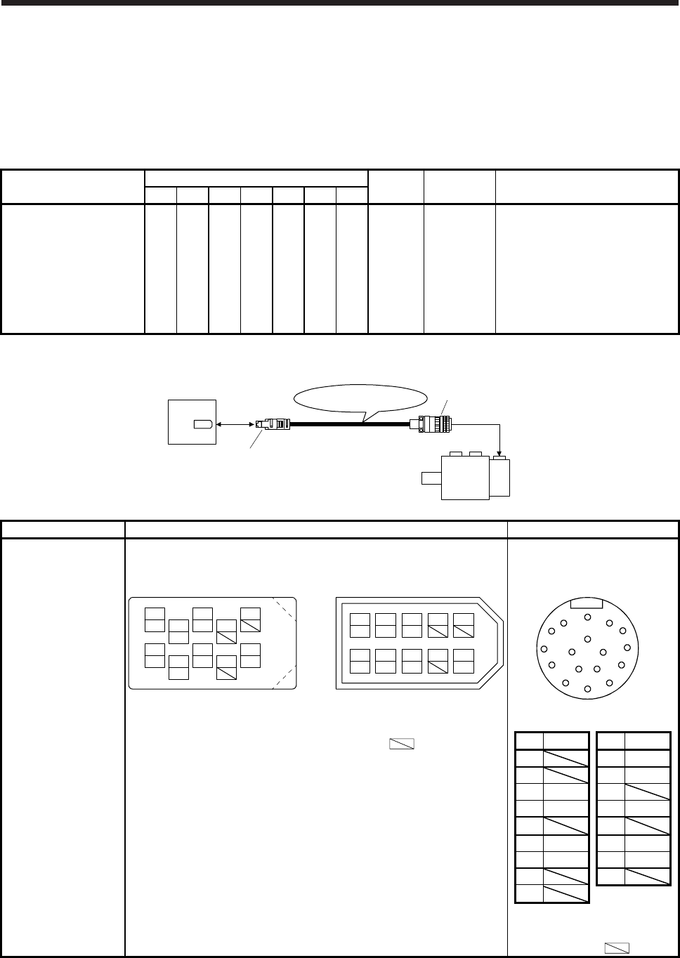
5. WIRING OPTION
5 - 22
(6) MR-ENECBL_M-H-MTH
These cables are encoder cables for HG-JR701M(4), HG-JR11K1M(4), HG-JR15K1M(4), HG-
JR22K1M(4), HG-JR30K1M(4), HG-JR37K1M(4), HG-JR45K1M4, HG-JR55K1M4, HG-JR601(4), HG-
JR801(4), HG-JR12K1(4), HG-JR15K1(4), HG-JR20K1(4), HG-JR25K1(4), HG-JR30K1(4), and HG-
JR37K1(4) servo motors. The numbers in the cable length field of the table indicate the symbol filling the
underline "_" in the cable model.
Cable model Cable length
IP rating Bending life Application
2 m 5 m 10 m 20 m 30 m 40 m 50 m
MR-ENECBL_M-H-MTH 2 5 10 20 30 40 50 IP67 Long
bending life
For HG-JR701M(4),
HG-JR11K1M(4), HG-JR15K1M(4),
HG-JR22K1M(4), HG-JR30K1M(4),
HG-JR37K1M(4), HG-JR45K1M4,
HG-JR55K1M4, HG-JR601(4),
HG-JR801(4), HG-JR12K1(4),
HG-JR15K1(4), HG-JR20K1(4),
HG-JR25K1(4), HG-JR30K1(4),
and HG-JR37K1(4)
(a) Connection of servo amplifier and servo motor
MR-ENECBL_M-H-MTH 2)
CN2
Servo motor
HG-JR701M(4) to HG-JR37K1M(4)
HG-JR45K1M4
HG-JR55K1M4
HG-JR601(4) to HG-JR37K1(4)
1)
Servo amplifier
Cable model 1) CN2-side connector 2) Encoder-side connector
MR-ENECBL_M-H-
MTH
Receptacle: 36210-0100PL
Shell kit: 36310-3200-008
(3M)
Connector set: 54599-1019 (Molex) Plug: D/MS3106A20-29S(D190)
Cable clamp: CE3057-12A-3-D
Backshell: CE02-20BS-S-D
1
P5 3
MR 79
BAT
4
MRR
2
LG 8610
5
View seen from wiring side. (Note)
or
4
MRR
THM2
THM1
THM2
THM1
2
LG 8
6
1
P5 5
10
3
MR 79
BAT
View seen from wiring side. (Note)
A
N
G
S R
TP
HF
JE
KD
LMBC
View seen from wiring side.
(Note)
Note. Do not connect anything to the pins shown as . Especially, pin
10 is provided for manufacturer adjustment. If it is connected with any
other pin, the servo amplifier cannot operate normally. Referring
POINT of section 5.2, securely connect the shielded cable external
conductor of the shielded cable to the ground plate and fix it to the
connector shell.
Pin Signal Pin Signal
A K THM1
B L THM2
C MR M
D MRR N SHD
E P
F BAT R LG
G LG S P5
H T
J
Note. Do not connect
anything to the pins
shown as .
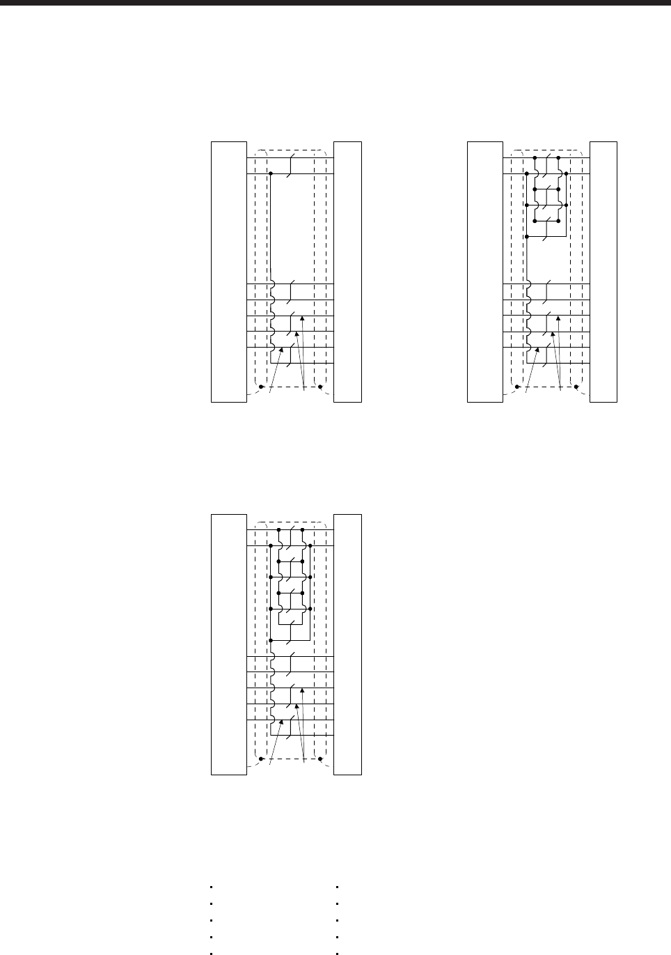
5. WIRING OPTION
5 - 23
(b) Cable internal wiring diagram
MR-ENECBL2M-H-MTH
MR-ENECBL5M-H-MTH
MR-ENECBL10M-H-MTH
MR-ENECBL20M-H-MTH
(Note 2)
(Note 1)
P5
LG
1
2
MR
MRR
3
4
THM1 5
THM2 6
F
S
CN2-side
connector Encoder-side
connector
9
SD Plate
C
D
K
R
N
LG
MR
MRR
THM1
L THM2
SHD
P5
BAT BAT
GLG
P5
LG
1
2
MR
MRR
3
4
F
S
CN2-side
connector Encoder-side
connector
9
SD Plate
C
D
R
N
LG
MR
MRR
T
HM1 5 K THM1
T
HM2 6 L THM2
SHD
P5
BAT BAT
GLG
(Note 2)
(Note 1)
MR-ENECBL30M-H-MTH
MR-ENECBL40M-H-MTH
MR-ENECBL50M-H-MTH
P5
LG
1
2
MR
MRR
3
4
THM2 6 L
F
S
K
CN2-side
connector Encoder-side
connector
THM1 5
9
SD Plate
C
D
R
N
LG
MR
MRR
THM2
THM1
SHD
P5
GLG
BAT BAT
(Note 2)
(Note 1)
Note 1.
A
lways make connection for use in an absolute position detection system. Wiring is not
necessary for use in an incremental system.
2.
A
lways make connection for use with the following servo motors. Wiring is not necessary for
use with other servo motors.
HG-JR22K1M(4)
HG-JR30K1M(4)
HG-JR37K1M(4)
HG-JR45K1M4
HG-JR55K1M4
HG-JR15K1(4)
HG-JR20K1(4)
HG-JR25K1(4)
HG-JR30K1(4)
HG-JR37K1(4)
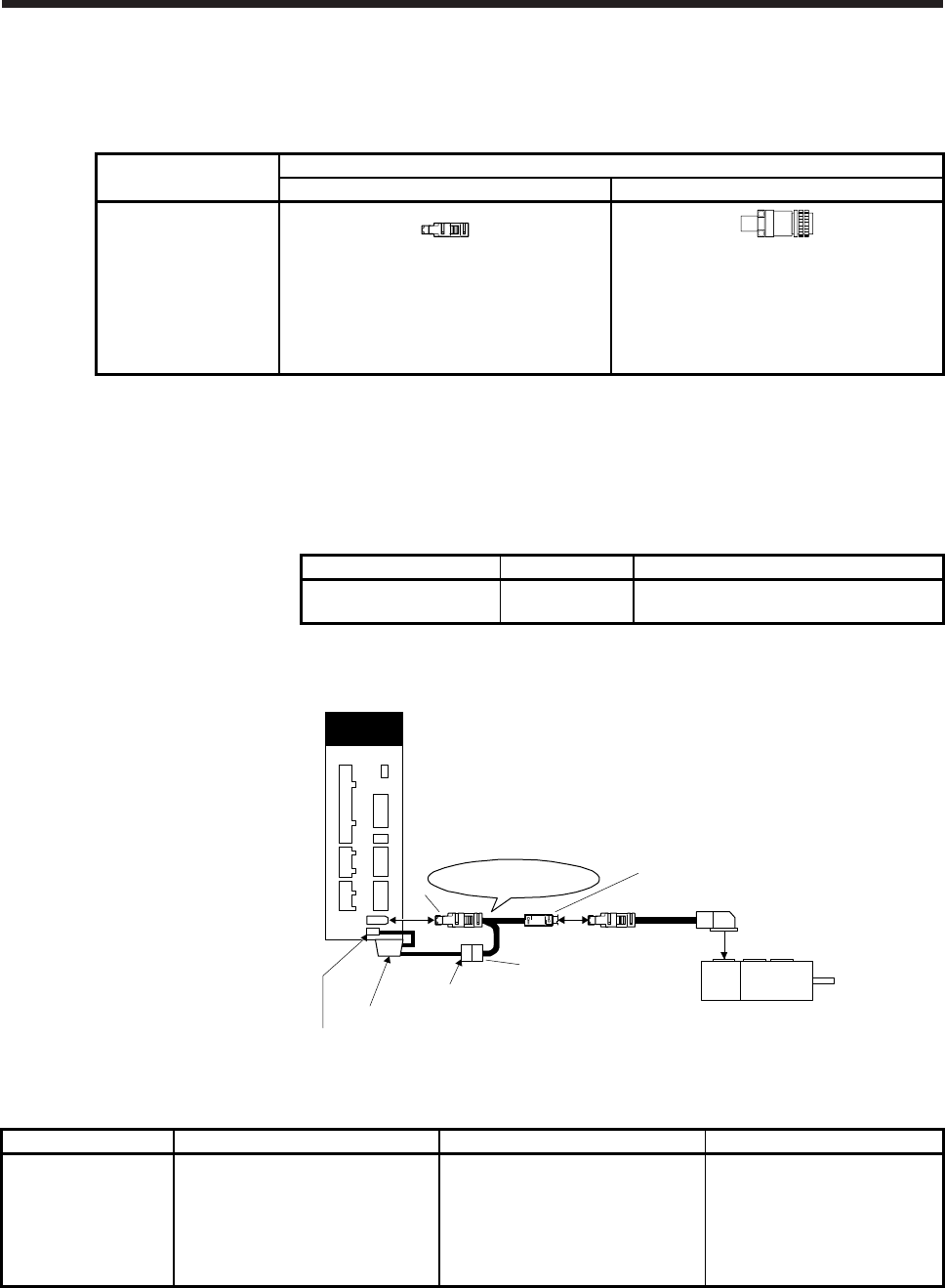
5. WIRING OPTION
5 - 24
(c) When fabricating the encoder cable
When fabricating the cable, prepare the following parts, and fabricate it according to the wiring
diagram in (b). Refer to section 5.6 for the specifications of the cable to use.
Parts
(Connector set)
Description
Servo amplifier-side connector Encoder-side connector (DDK)
MR-ENECNS
Receptacle: 36210-0100PL
Shell kit: 36310-3200-008
(3M)
or
Connector set: 54599-1019
(Molex)
Plug: D/MS3106A20-29S(D190)
Cable clamp: CE3057-12A-3-D
Backshell: CE02-20BS-S-D
(7) MR-BT6VCBL03M
This cable is a battery connection cable. Using this cable with an MR-BAT6V1BJ enables to hold
absolute position data recorded in the encoder even if they are disconnected from the servo amplifier.
Additionally, you can change the battery with the control circuit power supply off. For details, refer to
each servo amplifier instruction manual.
Cable model Cable length Application
MR-BT6VCBL03M 0.3 m
For HG-MR/HG-KR/HG-SR/HG-JR/HG-
RR/HG-UR series
Connection of servo amplifier and servo motor
CN2
CN4
Servo amplifie
r
Orange: Connector for servo amplifier
Black: Connector for branch cable
(Note)
Encoder cable
HG series servo motors
MR-BT6VCBL03M
MR-BAT6V1BJ
1)
2)
3)
Note. For the encoder cable, refer to (1) to (6) of this section.
Cable model 1) CN2-side connector 2) Junction connector 3) Battery connector
MR-BT6VCBL03M Receptacle: 36210-0100PL
Shell kit: 36310-3200-008
(3M)
or
Connector set: 54599-1019
(Molex)
Plug: 36110-3000FD
Shell kit: 36310-F200-008
(3M)
Connector: DF3-2EP-2C
Contact: DF3-EP2428PCFA
(Hirose Electric)
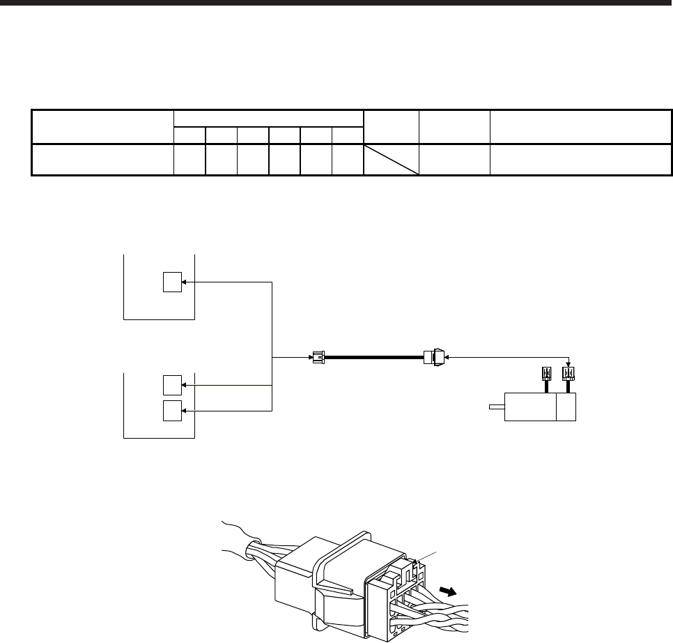
5. WIRING OPTION
5 - 25
(8) MR-J3W03ENCBL_M-A-H
These cables are encoder cables for the HG-AK series servo motors. The numbers in the cable length
field of the table indicate the symbol filling the underline "_" in the cable model.
Cable model Cable length
IP rating Bending life Application
1 m 2 m 5 m 10 m 20 m 30 m
MR-J3W03ENCBL_M-A-H 1 2 5 10 20 30 Long
bending life HG-AK series
(a) Connection of servo amplifier and servo motor
MR-J3W03ENCBL_M-A-H
1) 2) Encoder connector
Servo motor
HG-AK
(Note)
MR-J4-03A6(-RJ)
servo amplifier
CN2
or
MR-J4W2-0303B6
servo amplifier
CN2A
CN2B
Note. Remove the connector by pressing the lock lever on the encoder connector. You do not need to press the
lock lever on the encoder cable.
Lock lever
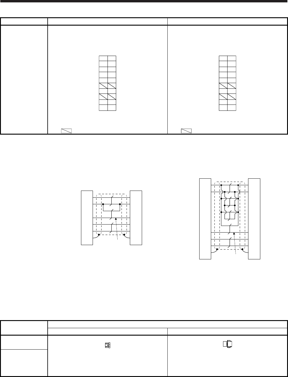
5. WIRING OPTION
5 - 26
Cable model 1) CN2, CN2A, and CN2B-side connector 2) Encoder-side connector
MR-J3W03ENCBL_
M-A-H
Receptacle housing: 1-1827862-5
Contact: 1827587-2
Crimping tool: 1762846-1
(TE Connectivity)
5B
4B
BAT
LG
3B
2B
1B
MRR
5A
4A
SD
P5
3A
2A
1A
MR
Tab housing: J21DPM-10V-KX
Contact: SJ2M-01GF-M1.0N
Crimping tool: YRS-8861
(JST)
5A
4A
BAT
LG
3A
2A
1A
MRR
5B
4B
SHD
P5
3B
2B
1B
MR
Note. Do not connect anything to the pins shown as
.
Note.Do not connect anything to the pins shown as
.
(b) Cable internal wiring diagram
(Note)
P5
LG
MR
MRR
5A
4B
CN2, CN2A, and
CN2B-side connector
Encoder-side
connector
1B
1A
4A
MR-J3W03ENCBL1M-A-H
MR-J3W03ENCBL2M-A-H
MR-J3W03ENCBL5M-A-H
MR-J3W03ENCBL10M-A-H
LG
MR
MRR
P5
BATBAT
SD 5B SHD
5B
4A
1A
1B
4B
5A
(Note)
P5
LG
MR
MRR
5A
4B
CN2, CN2A, and
CN2B-side connector
Encoder-side
connector
1B
1A
4A
MR-J3W03ENCBL20M-A-H
MR-J3W03ENCBL30M-A-H
LG
MR
MRR
P5
BATBAT
SD 5B SHD
5B
4A
1A
1B
4B
5A
Note.
A
lways make connection for use in an absolute position detection system. Wiring is not necessary for use
in an incremental system.
(c) When fabricating the encoder cable
When fabricating the cable, prepare the following parts, and fabricate it according to the wiring
diagram in (8) (b) of this section. Refer to section 5.6 for the specifications of the cable to use.
Connector set
model
Description
CN2, CN2A, and CN2B side connector Encoder-side connector
MR-J3W03CN2-2P
Receptacle housing: 1-1827862-5
Contact: 1827587-2
(TE Connectivity)
Tab housing: J21DPM-10V-KX
Contact: SJ2M-01GF-M1.0N
(JST)
MR-J3W03CN2-20P
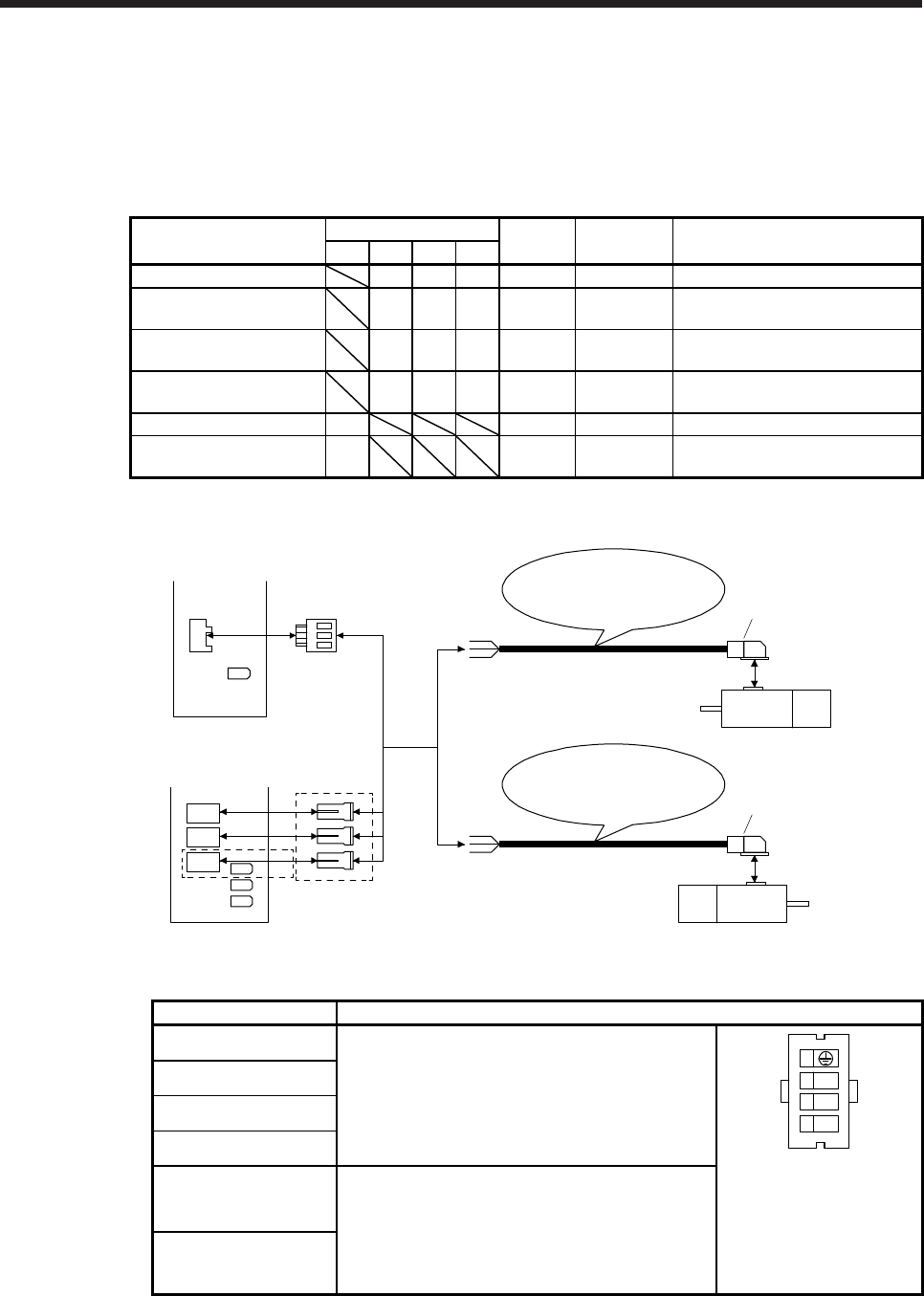
5. WIRING OPTION
5 - 27
5.3 Servo motor power cable
These cables are servo motor power cables for the HG-MR/HG-KR series servo motors.
The numbers in the cable length field of the table indicate the symbol filling the underline "_" in the cable
model.
Refer to section 4.2.1 for wiring.
Cable model Cable length IP rating Bending life Application
0.3 m 2 m 5 m 10 m
MR-PWS1CBL_M-A1-L 2 5 10 IP65 Standard Load-side lead for HG-MR/HG-KR
MR-PWS1CBL_M-A2-L 2 5 10 IP65 Standard
Opposite to load-side lead for HG-
MR/HG-KR
MR-PWS1CBL_M-A1-H 2 5 10 IP65 Long
bending life Load-side lead for HG-MR/HG-KR
MR-PWS1CBL_M-A2-H 2 5 10 IP65 Long
bending life
Opposite to load-side lead for HG-
MR/HG-KR
MR-PWS2CBL03M-A1-L 03 IP55 Standard Load-side lead for HG-MR/HG-KR
MR-PWS2CBL03M-A2-L 03 IP55 Standard
Opposite to load-side lead for HG-
MR/HG-KR
(1) Connection of servo amplifier and servo motor
1)
Servo motor
HG-MR
HG-KR
MR-PWS1CBL_M-A2-L
MR-PWS1CBL_M-A2-H
MR-PWS2CBL03M-A2-L
1)
Servo motor
HG-MR
HG-KR
MR-PWS1CBL_M-A1-L
MR-PWS1CBL_M-A1-H
MR-PWS2CBL03M-A1-L
or
CNP3A
CNP3B
CNP3C
CNP3
(Note)
or
MR-J4 multi-axis
servo amplifier
MR-J4 1-axis
servo amplifier
Connector for CNP3 packed
with the servo amplifier
Connector for CNP3A, CNP3B and
CNP3C packed with the servo amplifier
Note. This connection is for the MR-J4 3-axis servo amplifier.
Cable model 1) Servo motor power-side connector
MR-PWS1CBL_M-A1-L Connector: KN4FT04SJ1-R
Hood, socket insulator
Bushing, ground nut
Contact: ST-TMH-S-C1B-100-(A534G)
Crimping tool: CT170-14-TMH5B
(JAE)
U
V
W
1
2
3
4
View seen from wiring side.
MR-PWS1CBL_M-A2-L
MR-PWS1CBL_M-A1-H
MR-PWS1CBL_M-A2-H
MR-PWS2CBL03M-A1-L
Connector: KN4FT04SJ2-R
Hood, socket insulator
Bushing, ground nut
Contact: ST-TMH-S-C1B-100-(A534G)
Crimping tool: CT170-14-TMH5B
(JAE)
MR-PWS2CBL03M-A2-L

5. WIRING OPTION
5 - 28
(2) Internal wiring diagram
(Red)
(White)
(Black)
(Green/yellow)
U
V
W
(Note)
Note. These are not shielded cables.
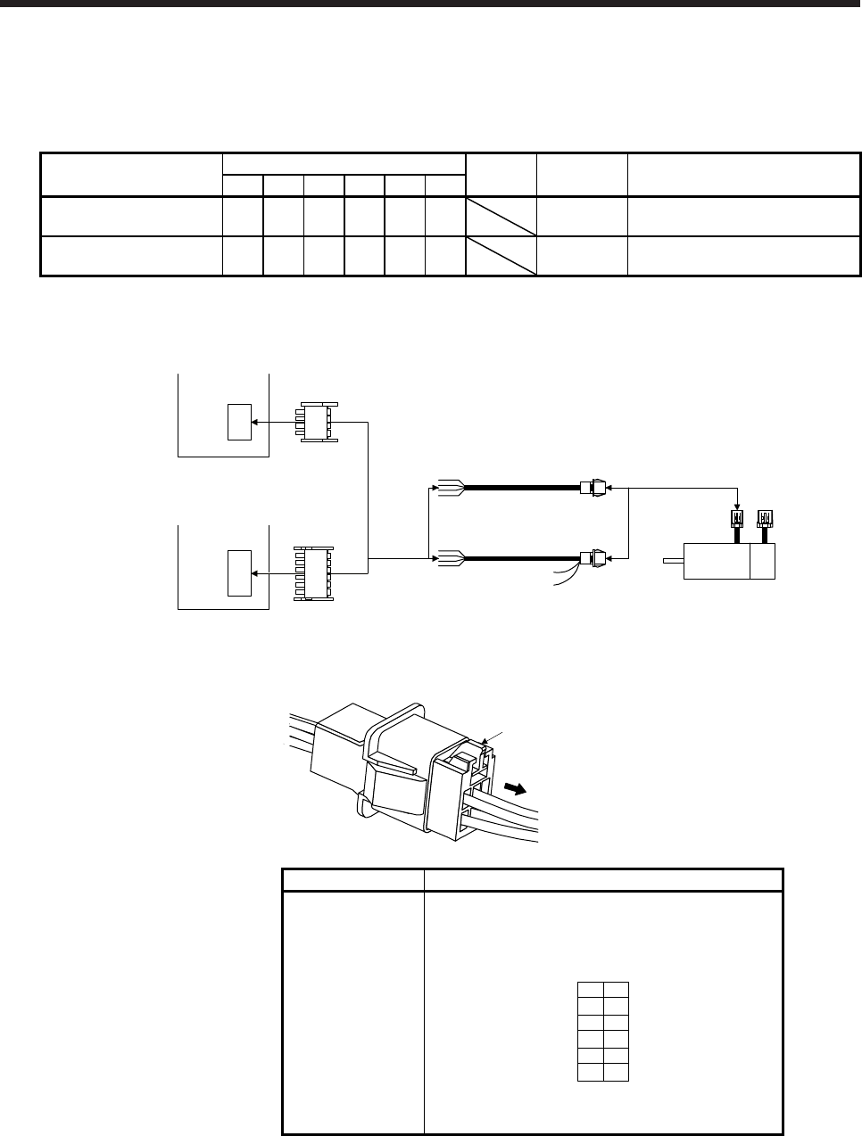
5. WIRING OPTION
5 - 29
5.4 Servo motor power cable (for HG-AK series)
These cables are servo motor power cables for the HG-AK series servo motors. The numbers in the cable
length field of the table indicate the symbol filling the underline "_" in the cable model.
Cable model Cable length
IP rating Bending life Application
1 m 2 m 5 m 10 m 20 m 30 m
MR-J4W03PWCBL_M-H 1 2 5 10 20 30 Long
bending life
For standard servo motor (without
electromagnetic brake)
MR-J4W03PWBRCBL_M-
H 1 2 5 10 20 30 Long
bending life
For servo motor with an
electromagnetic brake
(1) Connection of servo amplifier and servo motor
MR-J4W03PWBRCBL_M-H
or Power
connector
Servo motor
HG-AK
(Note)
(Note)
MR-J4-03A6(-RJ)
servo amplifier
or
MR-J4W2-0303B6
servo amplifier
CNP1
CNP1
MR-J4W03PWCBL_M-H
Note. Remove the connector by pressing the lock lever on the power connector. You do not need to press the
lock lever on the servo motor power cable.
Lock lever
Cable model Servo motor-side connector
MR-
J4W03PWCBL_M-
H
MR-
J4W03PWBRCBL_
M-H
Tab housing: J21DPM-06V-KX
Contact: SJ2M-21GF-M1.0N
Crimping tool: YRF-1120
(JST)
B2B1
2A
3A 3B
2B
1B1A
VE
WU
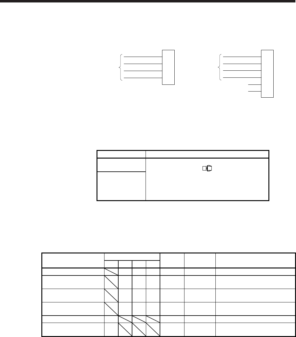
5. WIRING OPTION
5 - 30
(2) Internal wiring diagram
1B
Servo motor power-
side connector
1A
MR-J4W03PWCBL_M-H
E
V
2B W
2A U
Yellow/green
White
Black
Red
(Note)
1B
Servo motor power-
side connector
1A
MR-J4W03PWBRCBL_M-H
E
V
2B W
2A U
3B B1
3A B2
Yellow/green
White
Black
Red
(Note)
Note. These are not shielded cables.
(3) When fabricating the motor power cable
When fabricating the cable, prepare the following parts, and fabricate it according to the wiring diagram
in (2) of this section. Refer to section 5.6 for the specifications of the cable to use.
Connector set model Servo motor-side connector
MR-J4W03CNP2-
2P
Tab housing: J21DPM-06V-KX
Contact: BJ2M-21GF-M1.0N
(JST)
MR-J4W03CNP2-
20P
5.5 Electromagnetic brake cable
These cables are electromagnetic brake cables for the HG-MR/HG-KR series servo motors. The numbers in
the cable length field of the table indicate the symbol filling the underline "_" in the cable model.
Refer to section 4.2.1 for wiring.
Cable model Cable length IP rating Bending life Application
0.3 m 2 m 5 m 10 m
MR-BKS1CBL_M-A1-L 2 5 10 IP65 Standard Load-side lead for HG-MR/HG-KR
MR-BKS1CBL_M-A2-L 2 5 10 IP65 Standard
Opposite to load-side lead for HG-
MR/HG-KR
MR-BKS1CBL_M-A1-H 2 5 10 IP65 Long
bending life Load-side lead for HG-MR/HG-KR
MR-BKS1CBL_M-A2-H 2 5 10 IP65 Long
bending life
Opposite to load-side lead for HG-
MR/HG-KR
MR-BKS2CBL03M-A1-L 03 IP55 Standard Load-side lead for HG-MR/HG-KR
MR-BKS2CBL03M-A2-L 03 IP55 Standard
Opposite to load-side lead for HG-
MR/HG-KR
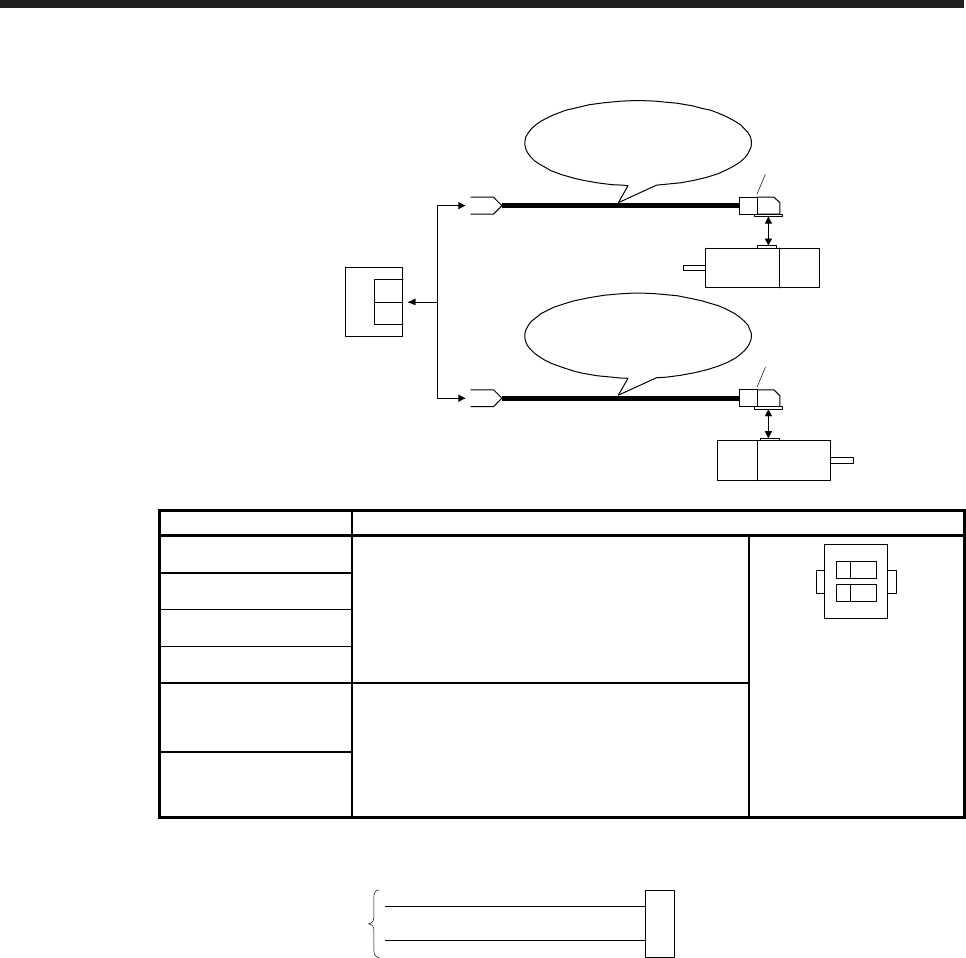
5. WIRING OPTION
5 - 31
(1) Connection of power supply for electromagnetic brake and servo motor
1)
Servo motor
HG-MR
HG-KR
+
-
24 V DC power
supply for
electromagnetic
brake
MR-BKS1CBL_M-A2-L
MR-BKS1CBL_M-A2-H
MR-BKS2CBL03M-A2-L
1)
Servo motor
HG-MR
HG-KR
MR-BKS1CBL_M-A1-L
MR-BKS1CBL_M-A1-H
MR-BKS2CBL03M-A1-L
or
Cable model 1) Connector for electromagnetic brake
MR-BKS1CBL_M-A1-L Connector: JN4FT02SJ1-R
Hood, socket insulator
Bushing, ground nut
Contact: ST-TMH-S-C1B-100-(A534G)
Crimping tool: CT170-14-TMH5B
(JAE)
View seen from wiring side.
B22
1B1
MR-BKS1CBL_M-A2-L
MR-BKS1CBL_M-A1-H
MR-BKS1CBL_M-A2-H
MR-BKS2CBL03M-A1-L
Connector: JN4FT02SJ2-R
Hood, socket insulator
Bushing, ground nut
Contact: ST-TMH-S-C1B-100-(A534G)
Crimping tool: CT170-14-TMH5B
(JAE)
MR-BKS2CBL03M-A2-L
(2) Internal wiring diagram
AWG 20
AWG 20
B1
B2
(Note)
Note. These are not shielded cables.

5. WIRING OPTION
5 - 32
5.6 Wires for option cables
When fabricating a cable, use the wire models given in the following table or equivalent.
Table 5.1 Wires for option cables
Type Model
Length
[m]
Core
size
Number
of cores
Characteristics of one core
(Note 2)
Cable OD
[mm]
Wire model
(Manufacturer)
Structure
[Wires/mm]
Conductor
resistance
[Ω/km]
(Note 1)
Insulator
OD
d [mm]
Encoder cable
MR-J3ENCBL_M-
A1-L 2 to 10 AWG 22 6
(3 pairs) 7/0.26 53
or less 1.18 7.1
(Note 3)
VSVP 7/0.26 (AWG #22 or
equivalent)-3P
KB-1655-2 (Bando Densen)
MR-J3ENCBL_M-
A2-L
MR-J3ENCBL_M-
A1-H 2 to 10 AWG 22 6
(3 pairs) 70/0.08 56
or less 1.17 7.1
(Note 3)
TPE SVP 70/0.08 (AWG #22
or equivalent)-3P
KB-2237-2 (Bando Densen)
MR-J3ENCBL_M-
A2-H
MR-J3JCBL03M-
A1-L 0.3 AWG 26 8
(4 pairs) 30/0.08 233
or less 1.2 7.1 ± 0.3 T/2464-1061/IIA-SB
4P×26AWG (Taiyo Cabletec)
MR-J3JCBL03M-
A2-L
MR-EKCBL_M-L
2 to 10
AWG 28 4
(2 pairs) 7/0.127 232
or less 1.18
7.0
(Note 3)
20276 composite 6-core
shielded cable
Ban-gi-shi-16395-1 (Bando
Densen)
AWG 22 2 17/0.16 28.7
or less 1.50
20 30 AWG 23 12
(6 pairs) 12/0.18 63.6
or less 1.2 8.2 ± 0.3
(Note 3)
20276 VSVPAWG#23×6P
KB-0492 (Bando Densen)
MR-EKCBL_M-H
2 to 10 0.2 mm2 12
(6 pairs) 40/0.08 105
or less 0.88 7.2
(Note 3) A14B2343 6P
(Junkosha)
20 AWG 24
12
(6 pairs) 40/0.08 105
or less 0.88 7.2
(Note 3)
TPE SVP 40/0.08 (AWG #24
or equivalent)-6P
KB-1928-2 (Bando Densen)
30 to 50 AWG 24 14
(7 pairs) 40/0.08 105
or less 0.88 8.0
(Note 3)
TPE SVP 40/0.08 (AWG #24
or equivalent)-7P
KB-1929-2 (Bando Densen)
MR-J3JSCBL03M-
A1-L 0.3 AWG 26 8
(4 pairs) 7/0.16 146
or less 1.0 7.1 ± 0.3
(Note 3)
VSVP 7/0.16 (AWG #26 or
equivalent)-4P
Ban-gi-shi-16822 (Bando
Densen)
MR-J3JSCBL03M-
A2-L
MR-J3ENSCBL_
M-L
2 to 10 AWG 22 6
(3 pairs) 7/0.26 53
or less 1.18 7.1
(Note 3)
VSVP 7/0.26 (AWG #22 or
equivalent)-3P
KB-1655-2 (Bando Densen)
20/30 AWG 23 12
(6 pairs) 12/0.18 63.3
or less 1.2 8.2 ± 0.3
(Note 3)
20276 VSVPAWG#23×6P
KB-0492 (Bando Densen)
MR-J3ENSCBL_
M-H
2 to 10 AWG 22 6
(3 pairs) 70/0.08 56
or less 1.17 7.1
(Note 3)
TPE SVP 70/0.08 (AWG #22
or equivalent)-3P
KB-2237-2 (Bando Densen)
20 to 50 AWG 24 12
(6 pairs) 40/0.08 105
or less 0.88 7.2
(Note 3)
TPE SVP 40/0.08 (AWG #24
or equivalent)-6P
KB-1928-2 (Bando Densen)
MR-ENECBL_M-
H-MTH
2 to 10 0.2 mm2 8
(4 pairs) 40/0.08 105
or less 0.88 7.2
(Note 3)
A14B2339 4P (Junkosha)
20 0.2 mm2 12
(6 pairs) 40/0.08 105
or less 0.88 7.2
(Note 3)
A14B2343 6P (Junkosha)
30 to 50 0.2 mm2 14
(7 pairs) 40/0.08 105
or less 0.88 8.0
(Note 3)
J14B0238(0.2*7P) (Junkosha)

5. WIRING OPTION
5 - 33
Type Model
Length
[m]
Core
size
Number
of cores
Characteristics of one core
(Note 2)
Cable OD
[mm]
Wire model
(Manufacturer)
Structure
[Wires/mm]
Conductor
resistance
[Ω/km]
(Note 1)
Insulator
OD
d [mm]
Encoder cable
MR-
J3W03ENCBL_M
-A-H
1 to 10 AWG 22 6 70/0.08 56
or less 1.17 7.1 ± 0.3
(Note 3)
TPE・SVP 70/0.08 (AWG #22
or equivalent)-3P
KB-2237-2 (Bando Densen)
20/30 AWG 22 10 70/0.08 56
or less 1.17 7.7 ± 0.3
(Note 3)
TPE・SVP 70/0.08 (AWG#22
or equivalent)-5P
(Bando Densen)
Servo motor power cable
MR-PWS1CBL_
M-A1-L 2 to 10
AWG 18 4 34/0.18 21.8
or less 1.71 6.2 ± 0.3
(Note 4)
HRZFEV-A (CL3) AWG 18 4
cores
(Dyden)
MR-PWS1CBL_
M-A2-L 2 to 10
MR-PWS1CBL_
M-A1-H 2 to 10 AWG 19
(0.75 mm2) 4 150/0.08
29.1
or less 1.63 5.7 ± 0.5
(Note 4)
RMFES-A (CL3X) AWG 19 4
cores
(Dyden)
MR-PWS1CBL_
M-A2-H 2 to 10
MR-
PWS2CBL03M-
A1-L
0.3
AWG 19 4 30/0.18 25.8
or less 1.64 -
(Note 3, 5)
J11B2330 UL10125
(Junkosha)
MR-
PWS2CBL03M-
A2-L
0.3
MR-
J4W03PWCBL_
M-H
1 to 30 AWG 19 4 150/0.08 29.1
or less 1.63 5.7 ± 0.5
(Note 4)
RMFES-A(CL3X) AWG 19, 4
cores
(Dyden)
MR-
J4W03PWBRCBL
_M-H
1 to 30 AWG 19 4 150/0.08 29.1
or less 1.63 5.7 ± 0.5
(Note 4)
RMFES-A(CL3X) AWG 19, 4
cores
(Dyden)
Electromagnetic brake cable
MR-BKS1CBL_
M-A1-L 2 to 10
AWG 20 2 21/0.18 34.6
or less 1.35 4.7 ± 0.1
(Note 4)
HRZFEV-A (CL3) AWG 20 2
cores
(Dyden)
MR-BKS1CBL_
M-A2-L 2 to 10
MR-BKS1CBL_
M-A1-H 2 to 10
AWG 20 2 110/0.08 39.0
or less 1.37 4.5 ± 0.3
(Note 4)
RMFES-A (CL3X) AWG 20 2
cores
(Dyden)
MR-BKS1CBL_
M-A2-H 2 to 10
MR-
BKS2CBL03M-
A1-L
0.3
AWG 20 2 19/0.203 32.0
or less 1.42 -
(Note 3, 5)
J11B2331 UL10125
(Junkosha)
MR-
BKS2CBL03M-
A2-L
0.3
Note 1. The following shows the detail of d.
InsulatorConductor
d
2. Standard OD. Max. OD is about 10% greater.
3. Purchase from Toa Electric Industrial Co. Ltd., Nagoya Branch
4. Purchase from Taisei Co., Ltd.
5. These models consist with solid wires. Specify the color, separately.

5. WIRING OPTION
5 - 34
MEMO
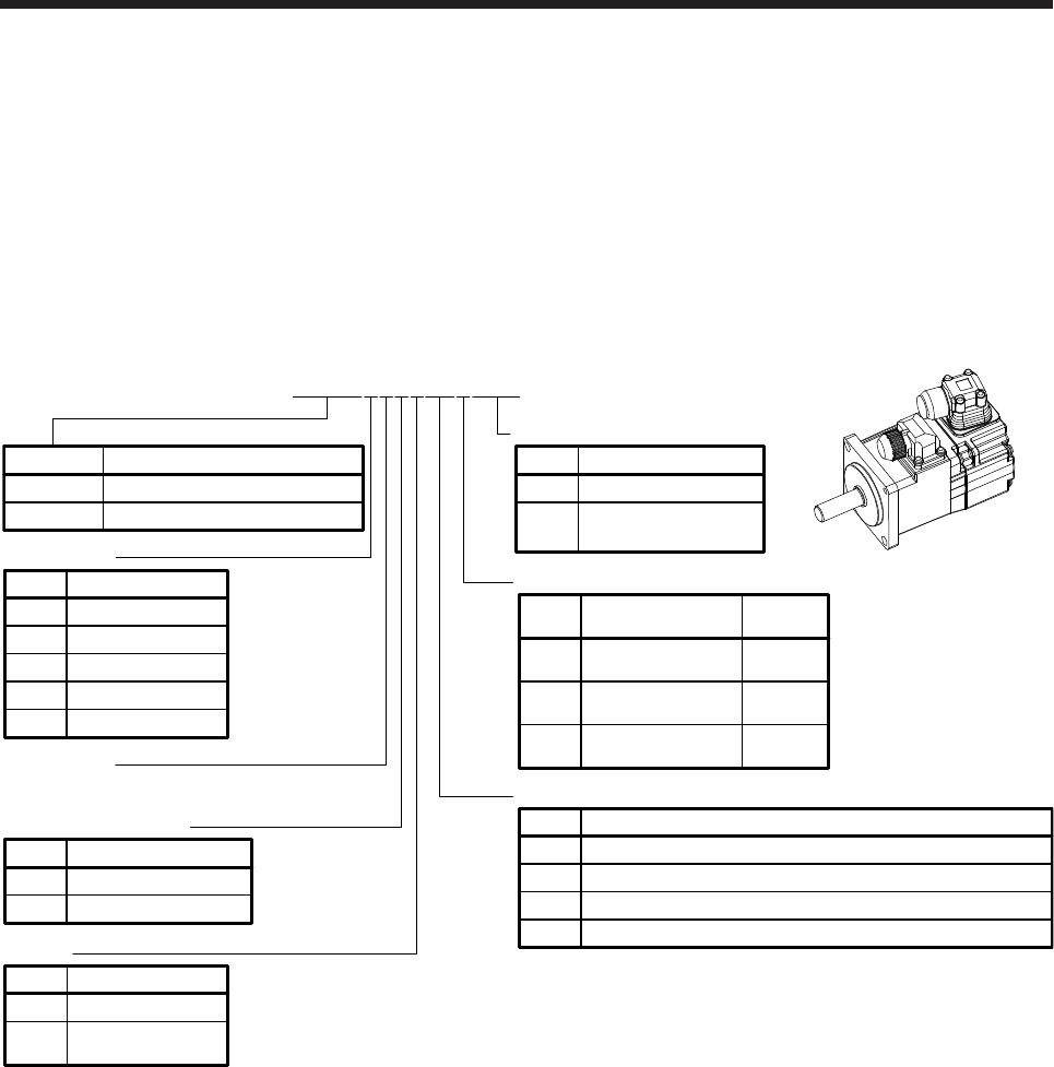
6. HG-MR SERIES/HG-KR SERIES
6 - 1
6. HG-MR SERIES/HG-KR SERIES
This chapter provides information on the servo motor specifications and characteristics. When using the HG-
MR/HG-KR series servo motor, always read the Safety Instructions in the beginning of this manual and
chapters 1 to 5, in addition to this chapter.
6.1 Model code definition
The following describes what each block of a model name indicates. Not all combinations of the symbols are
available.
Low inertia/Small capacity
Appearance
Shaft type
Symbol Shaft shape
None Standard
(straight shaft)
(Note 1)
K
(Note 1)
D
Keyway shaft
(with key)
D cut shaft
053 to 73
HG-MR_
HG-KR_
23 to 73
053/13
Rated speed
3000 [r/min]
None None
Electromagnetic brake
Symbol Electromagnetic brake
BWith
None None
Oil seal
Symbol Oil seal
(Note 2)
JWith
05 0.05
Rated output
Symbol Rated output [kW]
1 0.1
2 0.2
4 0.4
7 0.75
None
Reducer
Symbol
G1 For general industrial machine (flange-mounting)
Flange-mounting flange output type for high precision application
Flange-mounting shaft output type for high precision application
Reducer
None
G5
G7
HG-MR Ultra-Low inertia/Small capacity
Series Feature
HG-KR
HG-KR13BJG1DW0C
None Standard
Special specification
Symbol Special specification
(Note 3)
W0C Servo motor with
functional safety
Note 1. The special shaft applies to the standard servo motor and servo motor with an electromagnetic brake. However, the key shaft
(with key) also applies to the servo motor with flange-mounting shaft output type reducer for high precision application.
2. For details, contact your local sales office.
3. Refer to section 1.5 for details.
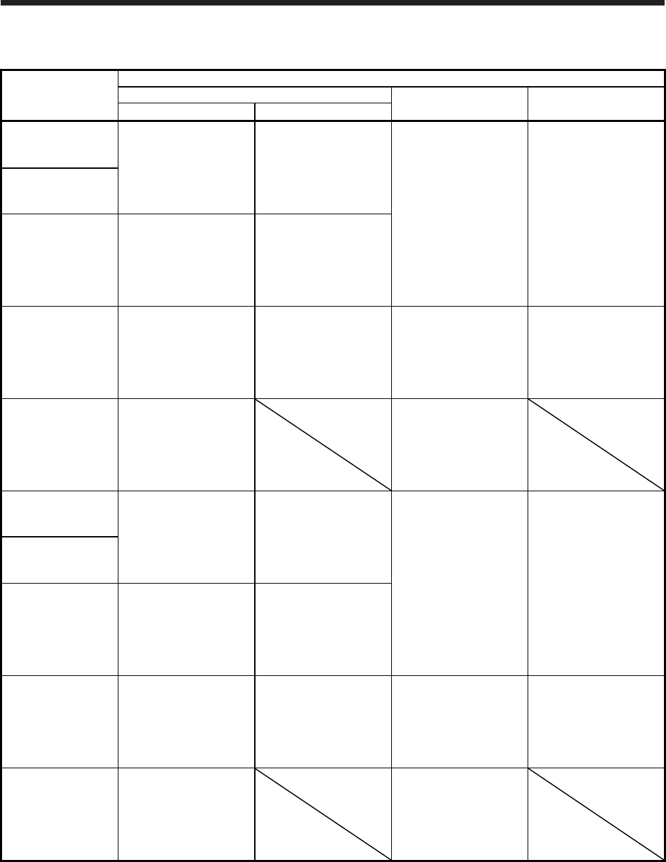
6. HG-MR SERIES/HG-KR SERIES
6 - 2
6.2 Combination list of servo motors and servo amplifiers
Servo motor
Servo amplifier
MR-J4 1-axis MR-J4 2-axis MR-J4 3-axis
200 V class 100 V class
HG-MR053
MR-J4-10A
MR-J4-10A-RJ
MR-J4-10B
MR-J4-10B-RJ
MR-J4-10B-RJ010
MR-J4-10B-RJ020
MR-J4-10A1
MR-J4-10A1-RJ
MR-J4-10B1
MR-J4-10B1-RJ
MR-J4-10B1-RJ020 MR-J4W2-22B
MR-J4W2-44B
MR-J4W3-222B
MR-J4W3-444B
HG-MR13
HG-MR23
MR-J4-20A
MR-J4-20A-RJ
MR-J4-20B
MR-J4-20B-RJ
MR-J4-20B-RJ010
MR-J4-20B-RJ020
MR-J4-20A1
MR-J4-20A1-RJ
MR-J4-20B1
MR-J4-20B1-RJ
MR-J4-20B1-RJ020
HG-MR43
MR-J4-40A
MR-J4-40A-RJ
MR-J4-40B
MR-J4-40B-RJ
MR-J4-40B-RJ010
MR-J4-40B-RJ020
MR-J4-40A1
MR-J4-40A1-RJ
MR-J4-40B1
MR-J4-40B1-RJ
MR-J4-40B1-RJ020
MR-J4W2-44B
MR-J4W2-77B
MR-J4W2-1010B
MR-J4W3-444B
HG-MR73
MR-J4-70A
MR-J4-70A-RJ
MR-J4-70B
MR-J4-70B-RJ
MR-J4-70B-RJ010
MR-J4-70B-RJ020
MR-J4W2-77B
MR-J4W2-1010B
HG-KR053
MR-J4-10A
MR-J4-10A-RJ
MR-J4-10B
MR-J4-10B-RJ
MR-J4-10B-RJ010
MR-J4-10B-RJ020
MR-J4-10A1
MR-J4-10A1-RJ
MR-J4-10B1
MR-J4-10B1-RJ
MR-J4-10B1-RJ020 MR-J4W2-22B
MR-J4W2-44B
MR-J4W3-222B
MR-J4W3-444B
HG-KR13
HG-KR23
MR-J4-20A
MR-J4-20A-RJ
MR-J4-20B
MR-J4-20B-RJ
MR-J4-20B-RJ010
MR-J4-20B-RJ020
MR-J4-20A1
MR-J4-20A1-RJ
MR-J4-20B1
MR-J4-20B1-RJ
MR-J4-20B1-RJ020
HG-KR43
MR-J4-40A
MR-J4-40A-RJ
MR-J4-40B
MR-J4-40B-RJ
MR-J4-40B-RJ010
MR-J4-40B-RJ020
MR-J4-40A1
MR-J4-40A1-RJ
MR-J4-40B1
MR-J4-40B1-RJ
MR-J4-40B1-RJ020
MR-J4W2-44B
MR-J4W2-77B
MR-J4W2-1010B
MR-J4W3-444B
HG-KR73
MR-J4-70A
MR-J4-70A-RJ
MR-J4-70B
MR-J4-70B-RJ
MR-J4-70B-RJ010
MR-J4-70B-RJ020
MR-J4W2-77B
MR-J4W2-1010B
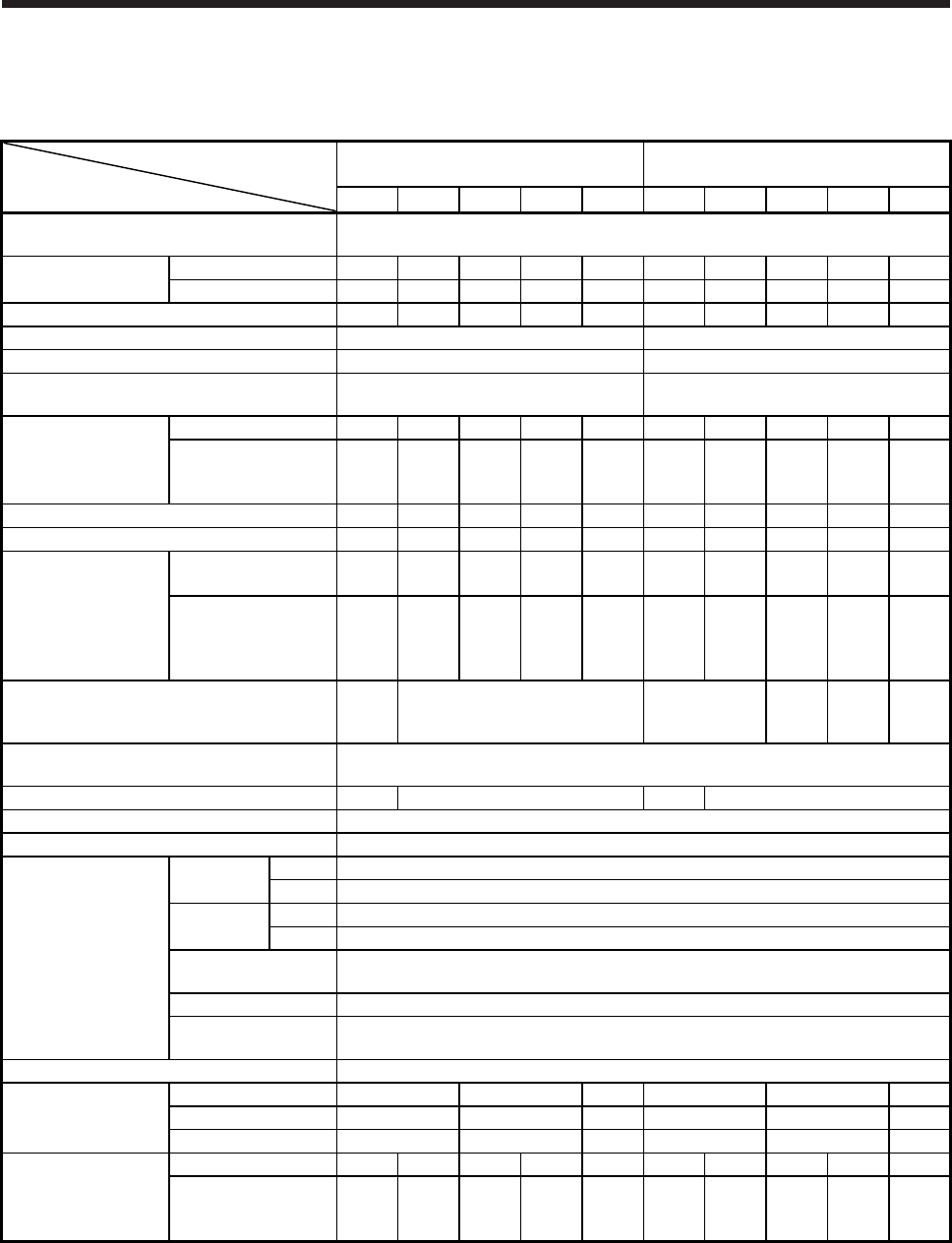
6. HG-MR SERIES/HG-KR SERIES
6 - 3
6.3 Standard specifications
6.3.1 Standard specifications list
Servo motor
Item
HG-MR series
(ultra-low inertia/small capacity) HG-KR series (low inertia/small capacity)
053(B) 13(B) 23(B) 43(B) 73(B) 053(B) 13(B) 23(B) 43(B) 73(B)
Power supply capacity Refer to "Power supply equipment capacity and generated loss of servo amplifiers" in
Servo Amplifier Instruction Manual.
Continuous running
duty (Note 1)
Rated output [kW] 0.05 0.1 0.2 0.4 0.75 0.05 0.1 0.2 0.4 0.75
Rated torque [N•m] 0.16 0.32 0.64 1.3 2.4 0.16 0.32 0.64 1.3 2.4
Maximum torque (Note 10) [N•m] 0.48 0.95 1.9 3.8 7.2 0.56 1.1 2.2 4.5 8.4
Rated speed (Note 1) [r/min] 3000 3000
Maximum speed (Note 10) [r/min] 6000 6000
Instantaneous permissible speed
(Note 10) [r/min] 6900 6900
Power rate at
continuous rated
torque
Standard [kW/s] 15.6 33.8 46.9 114.2 97.3 5.63 13.0 18.3 43.7 45.2
With an
electromagnetic brake
[kW/s]
11.3 28.0 37.2 98.8 82.1 5.37 12.1 16.7 41.3 41.6
Rated current [A] 1.0 0.9 1.5 2.6 5.8 0.9 0.8 1.3 2.6 4.8
Maximum current [A] 3.1 2.5 5.3 9.0 20 3.2 2.5 4.6 9.1 17
Moment of inertia J
(Note 3)
Standard
[× 10-4 kg•m2] 0.0162 0.0300 0.0865 0.142 0.586 0.0450 0.0777 0.221 0.371 1.26
With an
electromagnetic
brake
[× 10-4 kg•m2]
0.0224 0.0362 0.109 0.164 0.694 0.0472 0.0837 0.243 0.393 1.37
Recommended load to motor inertia ratio
(Note 2, 10)
35
times
or less
32 times or less 17 times or less
26
times
or less
25
times
or less
17
times
or less
Speed/position detector 22-bit encoder common to absolute position/incremental systems
(resolution per servo motor revolution: 4194304 pulses/rev)
Oil seal None None (Note 11) None None (Note 11)
Insulation class 130 (B)
Structure Totally-enclosed, natural-cooling (IP rating: IP65 (Note 4, 9))
Environment
Ambient
temperature
Operation 0 °C to 40 °C (non-freezing)
Storage -15 °C to 70 °C (non-freezing)
Ambient
humidity
Operation 80 %RH or less (non-condensing)
Storage 90 %RH or less (non-condensing)
Ambience Indoors (no direct sunlight), free from corrosive gas, flammable gas,
oil mist, dust, and dirt
Altitude Max. 1000 m above sea level
Vibration resistance
(Note 6) X, Y: 49 m/s2
Vibration rank (Note 7) V10
Permissible load for
the shaft
(Note 8, 10)
L [mm] 25 30 40 25 30 40
Radial [N] 88 245 392 88 245 392
Thrust [N] 59 98 147 59 98 147
Mass (Note 3)
Standard [kg] 0.34 0.54 0.91 1.4 2.8 0.34 0.54 0.91 1.4 2.8
With an
electromagnetic brake
[kg]
0.54 0.74 1.3 1.8 3.8 0.54 0.74 1.3 1.8 3.8
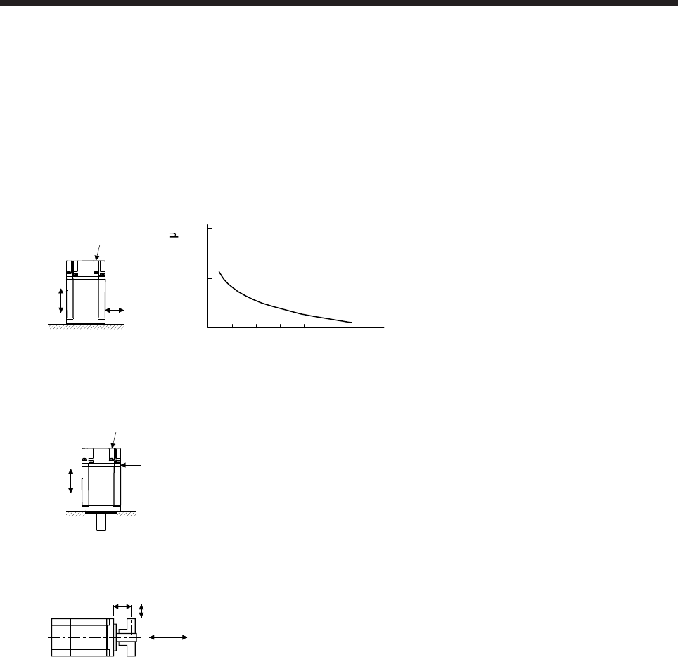
6. HG-MR SERIES/HG-KR SERIES
6 - 4
Note 1. When the power supply voltage drops, the output and the rated speed cannot be guaranteed.
2. If the load to motor inertia ratio exceeds the indicated value, contact your local sales office.
3. Refer to the dimensions for the geared servo motor.
4. Except for the shaft-through portion. IP classifies the degrees of protection provided against the intrusion of solid objects and
water in electrical enclosures.
5. In the environment where the servo motor is exposed to oil mist, oil, or water, the servo motor of the standard specifications
may not be usable. Please contact your local sales office.
6. The following figure shows the vibration directions. The value is the one at the part that indicates the maximum value (normally
the opposite to load-side bracket). When the servo motor stops, fretting is likely to occur at the bearing. Therefore, suppress
the vibration to about half of the permissible value. Note that this does not apply to the geared servo motor.
Y
X
Servo motor
Vibration
(both amplitudes) [ m]
Speed [r/min]
0 1000 2000 3000 4000 5000 6000 7000
10
100
1000
Vibration amplitude
7. V10 indicates that the amplitude of a single servo motor is 10 μm or less. The following figure shows the servo motor mounting
position for measurement and the measuring position.
Servo motor
Top
Bottom
Measuring position
8. The following shows permissible load for the shaft. Do not subject the shaft to load greater than the value in the specifications
list. The value assumes that the load is applied independently.
L
Radial load
Thrust load
L: Distance from flange mounting surface to load center
9. For the geared servo motor, the reducer area is IP44-equivalent.
10. Refer to section 6.6 for the geared servo motor.
11. The servo motors with an oil seal are also available. For details, contact your local sales office.
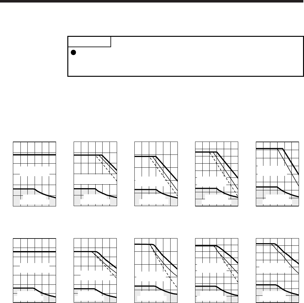
6. HG-MR SERIES/HG-KR SERIES
6 - 5
6.3.2 Torque characteristics
POINT
For the system where the unbalanced torque occurs, such as a vertical axis
system, the unbalanced torque of the machine should be kept at 70% or less of
the rated torque.
When the power supply input of the servo amplifier is 3-phase 200 V AC or 1-phase 230 V AC, the torque
characteristic is indicated by the heavy line. For the 1-phase 200 V AC power supply, part of the torque
characteristic is indicated by the thin line. For the 1-phase 100 V AC power supply, part of the torque
characteristic is indicated by the broken line.
[HG-MR053]
0 100020003000400050006000
Speed [r/min]
Continuous
running range
Short-duration
running range
Torque [N•m]
0.1
0.2
0.3
0.4
0.5
0.6
0
[HG-MR13]
100020003000400050006000
Speed [r/min]
Continuous
running range
Short-duration
running range
Torque [N•m]
0.2
0.4
0.6
0.8
1
1.2
0
0
[HG-MR23]
100020003000400050006000
0
Speed [r/min]
Continuous
running range
Short-duration
running range
Torque [N•m]
0.5
1
1.5
2
0
2.5
[HG-MR43]
100020003000400050006000
Speed [r/min]
Continuous
running range
Short-duration
running range
Torque [N•m]
0
0
1
2
3
4
0.5
1.5
2.5
3.5
4.5
[HG-MR73]
0 100020003000400050006000
1
2
3
4
5
6
7
8
Speed [r/min]
Continuous
running range
Short-duration
running range
Torque [N•m]
0
0 100020003000400050006000
Speed [r/min]
Continuous
running range
Short-duration
running range
Torque [N•m]
[HG-KR053]
0.1
0.2
0.3
0.4
0.5
0.7
0.6
0
[HG-KR13]
100020003000400050006000
0
Speed [r/min]
Continuous
running range
Short-duration
running range
Torque [N•m]
0
0.2
0.4
0.6
0.8
1.2
1.4
1
[HG-KR23]
100020003000400050006000
0
0.5
1
1.5
2
2.5
0
Speed [r/min]
Continuous
running range
Short-duration
running range
Torque [N•m]
[HG-KR43]
100020003000400050006000
0
Speed [r/min]
Continuous
running range
Short-duration
running range
Torque [N•m]
0.5
1
1.5
2
2.5
3
3.5
4
4.5
5
0
[HG-KR73]
0 100020003000400050006000
Speed [r/min]
Continuous
running range
Short-duration
running range
1
2
3
4
5
6
7
8
9
0
Torque [N•m]
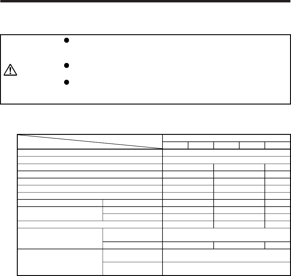
6. HG-MR SERIES/HG-KR SERIES
6 - 6
6.4 Electromagnetic brake characteristics
CAUTION
The electromagnetic brake is provided to prevent a drop at a power failure or
servo alarm occurrence during vertical drive or to hold a shaft at a stop. Do not
use it for normal braking (including braking at servo-lock).
Before performing the operation, be sure to confirm that the electromagnetic
brake operates properly.
The operation time of the electromagnetic brake differs depending on the power
supply circuit you use. Be sure to check the operation delay time with a real
machine.
The characteristics of the electromagnetic brake provided for the servo motor with an electromagnetic brake
are indicated below.
Servo motor
Item
HG-MR Series/HG-KR Series
053B 13B 23B 43B 73B
Type (Note 1) Spring actuated type safety brake
Rated voltage (Note 4) 24 V DC 0
-10%
Power consumption [W] at 20 °C 6.3 7.9 10
Coil resistance (Note 6) [Ω] 91.0 73.0 57.0
Inductance (Note 6) [H] 0.15 0.18 0.13
Brake static friction torque [N•m] 0.32 1.3 2.4
Release delay time (Note 2) [s] 0.03 0.03 0.04
Braking delay time (Note 2) [s] DC off 0.01 0.02 0.02
Permissible braking work Per braking [J] 5.6 22 64
Per hour [J] 56 220 640
Brake looseness at servo motor shaft (Note 5) [degrees] 2.5 1.2 0.9
Brake life (Note 3)
Number of brakings
[times] 20000
Work per braking [J] 5.6 22 64
Selection example of surge absorbers
to be used
(Note 7, 8)
For the suppressed
voltage 125 V TND20V-680KB
For the suppressed
voltage 350 V TND10V-221KB
Note 1. There is no manual release mechanism. When it is necessary to hand-turn the servo motor shaft for machine
centering, etc., use a separate 24 V DC power supply to release the brake electrically.
2. The value for initial on gap at 20 °C.
3. The brake gap will increase as the brake lining wears, but the gap is not adjustable.
The brake life indicated is the number of braking cycles after which adjustment will be required.
4.
A
lways prepare a power supply exclusively used for the electromagnetic brake.
5. These are design values. These are not guaranteed values.
6. These are measured values. These are not guaranteed values.
7. Select the electromagnetic brake control relay properly, considering the characteristics of the electromagnetic brake
and surge absorber. When you use a diode for a surge absorber, the electromagnetic braking time will be longer.
8. Manufactured by Nippon Chemi-Con Corporation.
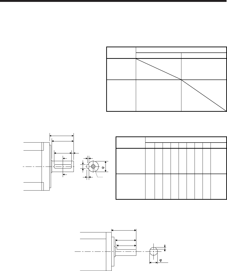
6. HG-MR SERIES/HG-KR SERIES
6 - 7
6.5 Servo motors with special shafts
The servo motors with special shafts indicated by the symbols (K and D) in the table are available. K and D
are the symbols included in the servo motor model names. Refer to section 6.6.2 (4) for geared servo motors
with special shaft.
Servo motor Shaft shape
Key shaft (with key) D cut shaft
HG-MR053(B)_
HG-MR13(B)_
HG-KR053(B)_
HG-KR13(B)_
D
HG-MR23(B)_
HG-MR43(B)_
HG-MR73(B)_
HG-KR23(B)_
HG-KR43(B)_
HG-KR73(B)_
K
6.5.1 Key shaft (with 2 round end key)
Q
A
A
QK
R
T
W
U
QL
Y
Shaft section view A-A
S
Variable dimension table [Unit: mm]
Servo motor Variable dimensions
S R Q W QK QL U T Y
HG-MR23(B)K
HG-MR43(B)K
HG-KR23(B)K
HG-KR43(B)K
14h6 30 26 5 20 3 3 5
M4
Screw
hole
depth
15
HG-MR73(B)K
HG-KR73(B)K 19h6 40 36 6 25 5 3.5 6
M5
Screw
hole
depth
20
6.5.2 D cut shaft
[Unit: mm]
8h6
25
21.5
20.5
1
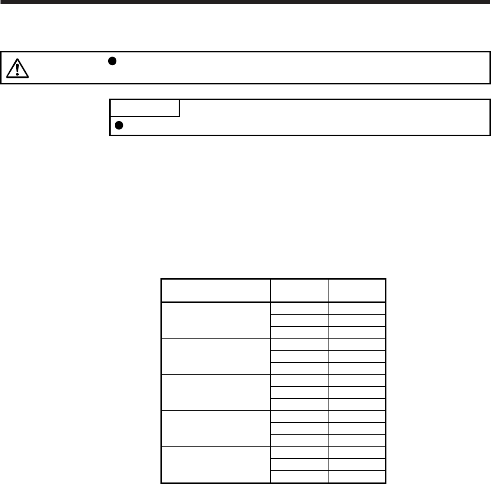
6. HG-MR SERIES/HG-KR SERIES
6 - 8
6.6 Geared servo motors
CAUTION For the geared servo motor, remove the oil before transportation and installation.
Tipping over the reducer filled with oil can cause oil leakage.
POINT
Geared servo motors are not included in the HG-MR series.
Servo motors are available with a reducer designed for general industrial machines and high precision
applications.
Servo motors with an electromagnetic brake are also available.
6.6.1 For general industrial machines (G1)
(1) Reduction ratio
The following table indicates the reduction ratios and actual reduction ratios of the geared servo motor
for general industrial machines.
Servo motor Nominal
reduction ratio
Actual
reduction ratio
1/5 9/44
HG-KR053(B)G1 1/12 49/576
1/20 25/484
1/5 9/44
HG-KR13(B)G1 1/12 49/576
1/20 25/484
1/5 19/96
HG-KR23(B)G1 1/12 961/11664
1/20 513/9984
1/5 19/96
HG-KR43(B)G1 1/12 961/11664
1/20 7/135
1/5 1/5
HG-KR73(B)G1 1/12 7/87
1/20 625/12544
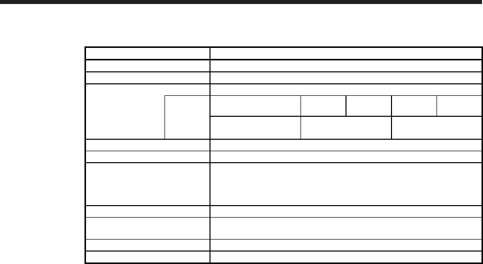
6. HG-MR SERIES/HG-KR SERIES
6 - 9
(2) Specifications
Item Description
Mounting method Flange mounting
Mounting direction In any directions
Lubrication method
Grease lubrication (already packed)
Packed
with
50 W/100 W 200 W/400 W
1/12, 1/20
750 W
1/12
200 W/400 W
1/5
750 W
1/5, 1/20
Mobilplex 46 Exxon
Mobil
Molynoc AP2
JX Nippon Oil & Energy
Mobil Grease SP
Exxon Mobil
Output shaft rotating direction Same as the servo motor output shaft direction.
Backlash (Note 3) 60 minutes or less at reducer output shaft
Permissible load inertia moment
ratio (converted into equivalent
value on servo motor shaft)
(Note 1)
50 W/100 W/750 W: 5 times or less
200 W/400 W: 7 times or less
Maximum torque Three times of the servo motor rated torque
Maximum speed
(at servo motor shaft) 4500 r/min (permissible instantaneous speed: 5175 r/min)
IP rating (reducer area) IP44 equivalent
Reducer efficiency (Note 2) 45% to 75%
Note 1. If the above indicated value is exceeded, please contact your local sales office.
2. The reducer efficiency differs depending on the reduction ratio. Also, it changes depending on the
operating conditions such as the output torque, speed and rotation, temperature, etc. The numerical
value in the table is a typical value in the rated torque, rated speed and rotation and typical
temperature, and not a guaranteed value.
3. The backlash can be converted: 1 min = 0.0167 °
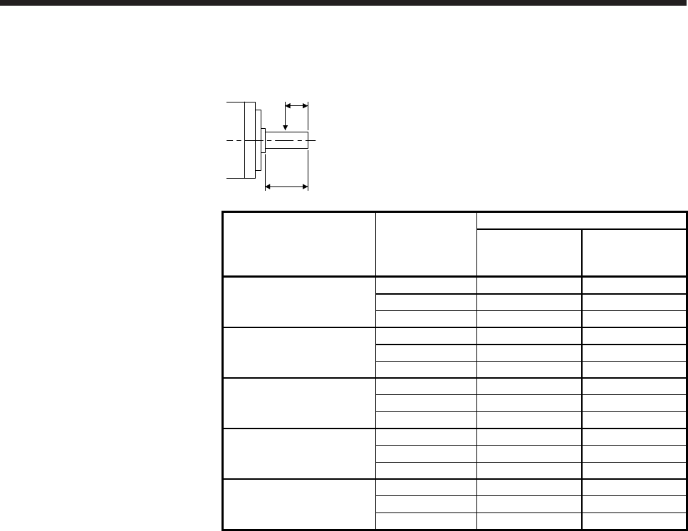
6. HG-MR SERIES/HG-KR SERIES
6 - 10
(3) Permissible loads of servo motor shaft
The permissible radial load in the table is the value measured at the center of the reducer output shaft.
Q: Length of axis (Refer to section 6.8.3, 6.8.4.)
Q/2
Q
Servo motor Reduction ratio
Permissible load (Note)
Permissible radial
load
[N]
Permissible thrust
load
[N]
1/5 150 200
HG-KR053(B)G1 1/12 240 320
1/20 370 450
1/5 150 200
HG-KR13(B)G1 1/12 240 320
1/20 370 450
1/5 330 350
HG-KR23(B)G1 1/12 710 720
1/20 780 780
1/5 330 350
HG-KR43(B)G1 1/12 710 720
1/20 760 760
1/5 430 430
HG-KR73(B)G1 1/12 620 620
1/20 970 960
Note. Do not subject the shaft to load greater than the value.
The value in the table assumes that the load is applied independently.
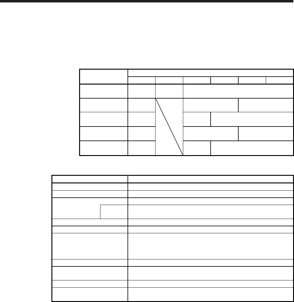
6. HG-MR SERIES/HG-KR SERIES
6 - 11
6.6.2 For high precision applications (G5/G7)
(1) Reduction ratio
The symbols (11B, 14A, 20A, and 32A) in the following table indicate the model numbers of the reducers
assembled to the servo motors. Servo motors with a reducer having the indicated reduction gear model
numbers are available. The reducer model number indicates _ _ _ of the reducer model HPG-_ _ _-05.
Servo motor Reduction ratio
1/5 1/9 1/11 1/21 1/33 1/45
HG-KR053(B)G5
HG-KR053(B)G7 11B/14A 11B 14A
HG-KR13(B)G5
HG-KR13(B)G7 11B/14A
14A 20A
HG-KR23(B)G5
HG-KR23(B)G7 14A 14A 20A
HG-KR43(B)G5
HG-KR43(B)G7 14A 20A 32A
HG-KR73(B)G5
HG-KR73(B)G7 20A 20A 32A
(2) Specifications
Item Description
Mounting method Flange mounting
Mounting direction In any directions
Lubrication method
Grease lubrication (already packed)
Packed
with
Harmonic grease SK-2
(Harmonic Drive Systems)
Output shaft rotating direction Same as the servo motor output shaft direction.
Backlash (Note 3) 3 minutes or less at reducer output shaft
Permissible load inertia moment
ratio (when converting into the
servo motor shaft)
(Note 1)
50 W/100 W/750 W: 10 times or less
200 W/400 W: 14 times or less
Maximum torque Three times of the servo motor rated torque
Maximum speed
(servo motor shaft) 6000 r/min (permissible instantaneous speed: 6900 r/min)
IP rating (reducer area) IP44 equivalent
Reducer efficiency
(Note 2) 50 W (reducer model No. 14A): 22% to 41%
50 W (reducer model No. 11B)/100 W/200 W/400 W/750 W: 58% to 87%
Note 1. If the above indicated value is exceeded, please contact your local sales office.
2. The reducer efficiency differs depending on the reduction ratio. Also, it changes depending on the
operating conditions such as the output torque, speed and rotation, temperature, etc. The numerical
value in the table is a typical value in the rated torque, rated speed and rotation and typical
temperature, and not a guaranteed value.
3. The backlash can be converted: 1 min = 0.0167 °
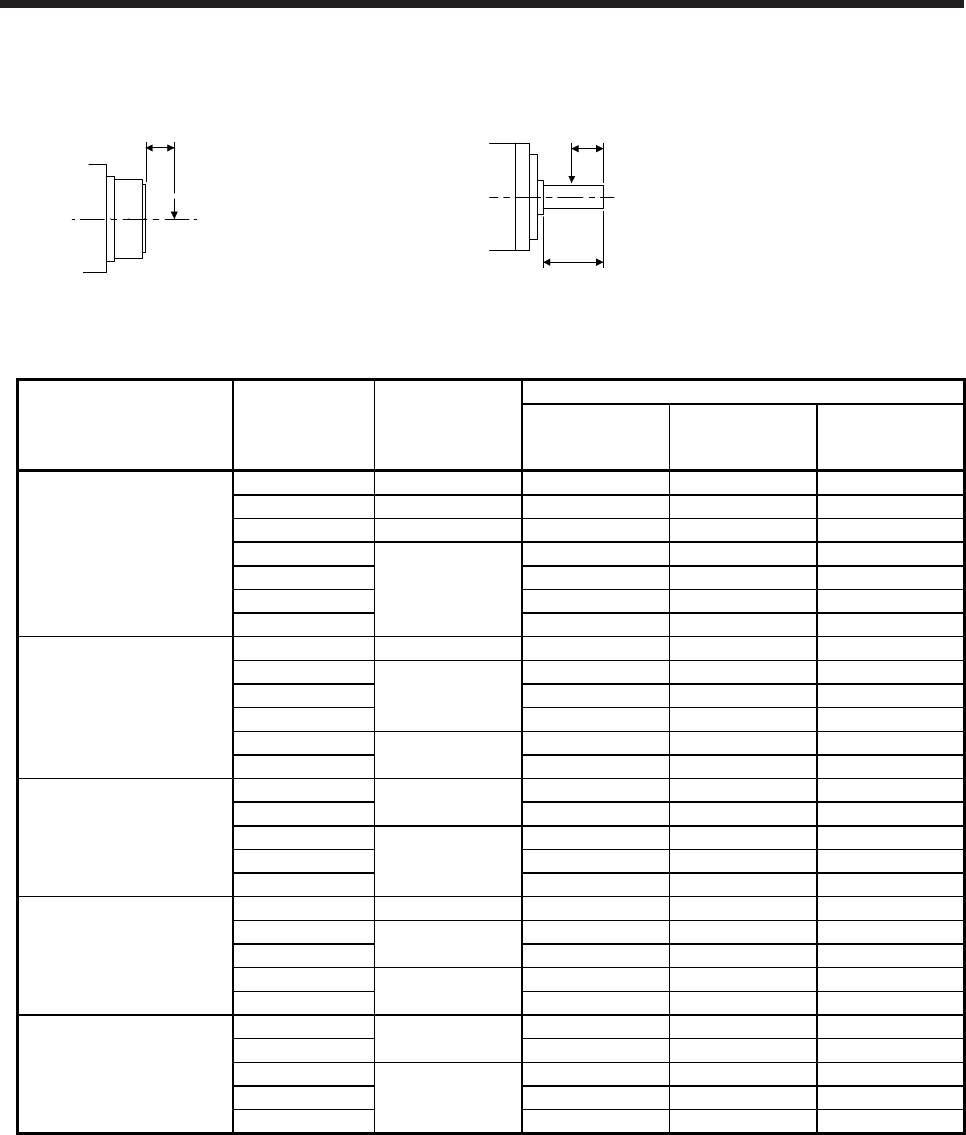
6. HG-MR SERIES/HG-KR SERIES
6 - 12
(3) Permissible loads of servo motor shaft
The radial load point of a high precision reducer is as shown below.
L: Distance between reducer
end face and load center
L
Q: Length of axis (Refer to section 6.8.7, 6.8.8.)
Q/2
Q
Flange-mounting flange output type for
high precision application (G5)
Flange-mounting shaft output type for
high precision application (G7)
Servo motor Reduction ratio Reducer model
number
Permissible load (Note)
Radial load point
L [mm]
Permissible radial
load
[N]
Permissible thrust
load
[N]
1/5 11B 17 93 431
1/5 14A 23 177 706
HG-KR053(B)G5
HG-KR053(B)G7
1/9 11B 17 111 514
1/11 23 224 895
1/21 14A 23 272 1087
1/33 23 311 1244
1/45 23 342 1366
1/5 11B 17 93 431
1/5 23 177 706
HG-KR13(B)G5
HG-KR13(B)G7
1/11 14A 23 224 895
1/21 23 272 1087
1/33
20A 32 733 2581
1/45 32 804 2833
1/5
14A 23 177 706
HG-KR23(B)G5
HG-KR23(B)G7
1/11 23 224 895
1/21 32 640 2254
1/33 20A 32 733 2581
1/45 32 804 2833
1/5 14A 23 177 706
HG-KR43(B)G5
HG-KR43(B)G7
1/11 20A 32 527 1856
1/21 32 640 2254
1/33 32A 57 1252 4992
1/45 57 1374 5478
1/5
20A 32 416 1465
HG-KR73(B)G5
HG-KR73(B)G7
1/11 32 527 1856
1/21 57 1094 4359
1/33 32A 57 1252 4992
1/45 57 1374 5478
Note. Do not subject the shaft to load greater than the value.
The value in the table assumes that the load is applied independently.
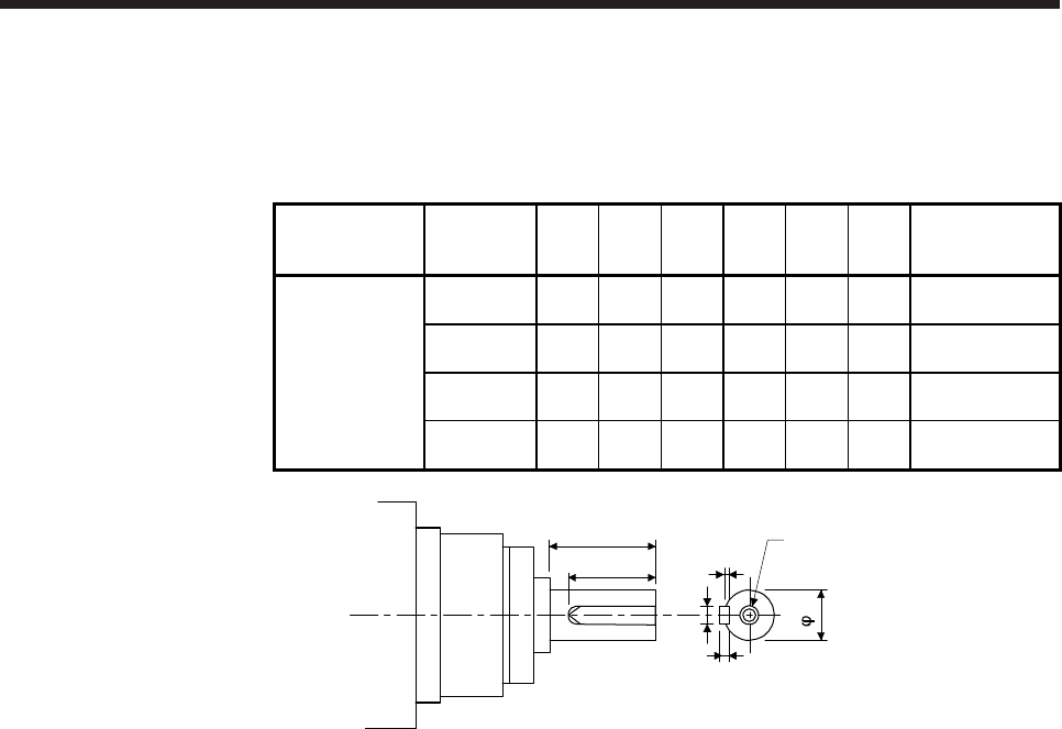
6. HG-MR SERIES/HG-KR SERIES
6 - 13
(4) Servo motor with special shaft
Servo motors with special shafts having keyway (with single pointed keys) are available for the flange-
mounting shaft output type for high precision applications (G7).
[Unit: mm]
Servo motor
Reducer
model
number
Q φS W T QK U Y
HG-KR_(B)G7K
11B 20 10h7 4 4 15 2.5
M3 screw hole
depth 6
14A 28 16h7 5 5 25 3
M4 screw hole
depth 8
20A 42 25h7 8 7 36 4
M6 screw hole
depth 12
32A 82 40h7 12 8 70 5
M10 screw hole
depth 20
U
W
T
Y
Q
QK
S
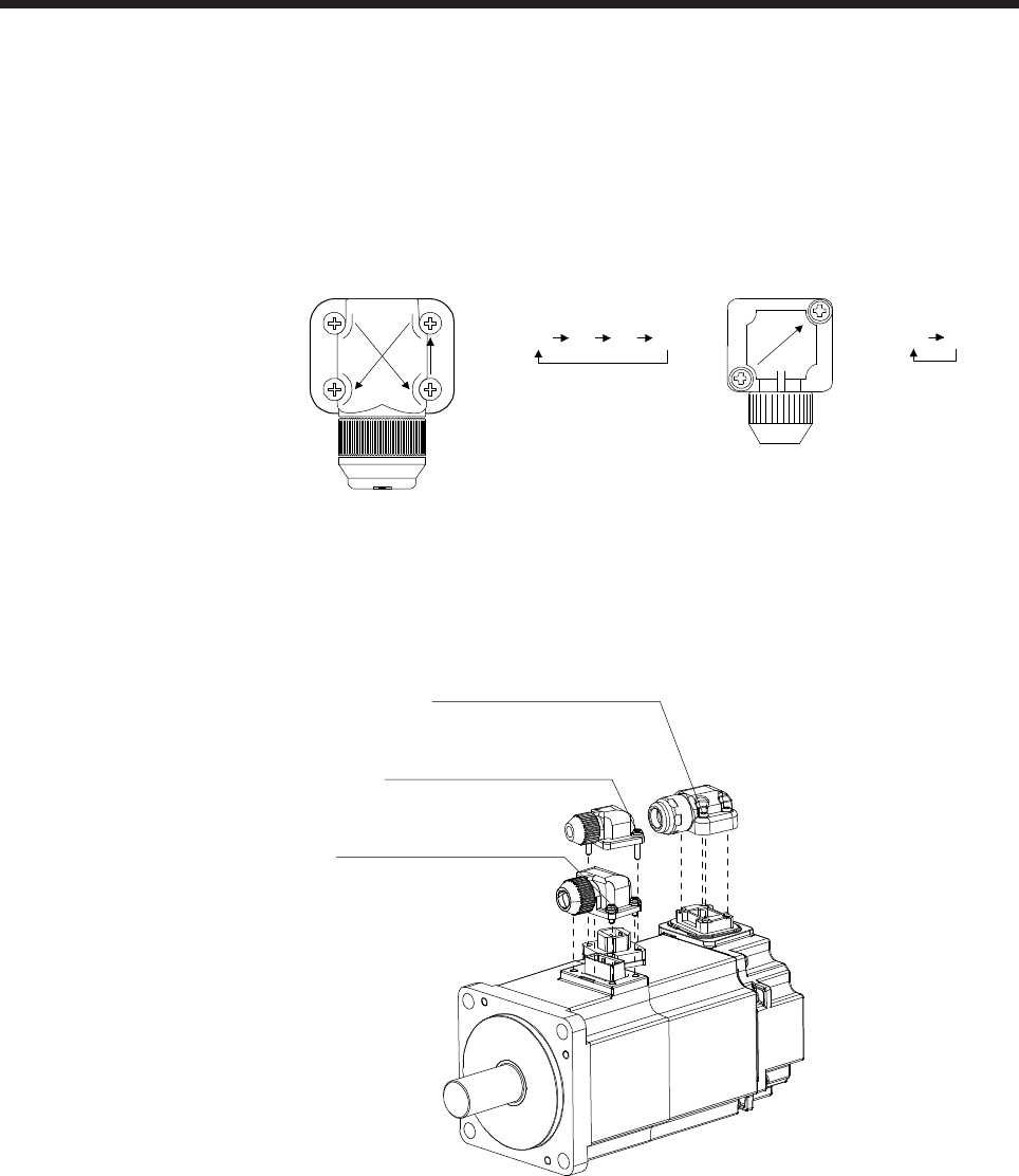
6. HG-MR SERIES/HG-KR SERIES
6 - 14
6.7 Mounting connectors
If the connector is not fixed securely, it may come off or may not produce a splash-proof effect during
operation.
To achieve the IP rating IP65, pay attention to the following points and install the connectors.
(1) When screwing the connector, hold the connector still and gradually tighten the screws in a crisscross
pattern.
1)
4
)
3)
2)
Tightening order
1) 2) 3) 4)
Tightening order
1) 2)
1)
2)
Connector for power supply, connector for
encoder
Connector for electromagnetic
brake
(2) Tighten the screws evenly. Tightening torques are as indicated below.
Connector for electromagnetic brake
Screw size: M2
Tightening torque: 0.2 [N•m]
Connector for power supply
Screw size: M2
Tightening torque: 0.2 [N•m]
Connector for encode
r
Screw size: M2
Tightening torque: 0.1 [N•m]
(3) The servo motor fitting part of each connector is provided with a splash-proof seal (O ring). When
mounting a connector, use care to prevent the seal (O ring) from dropping and being pinched. If the seal
(O ring) has dropped or is pinched, a splash-proof effect is not produced.
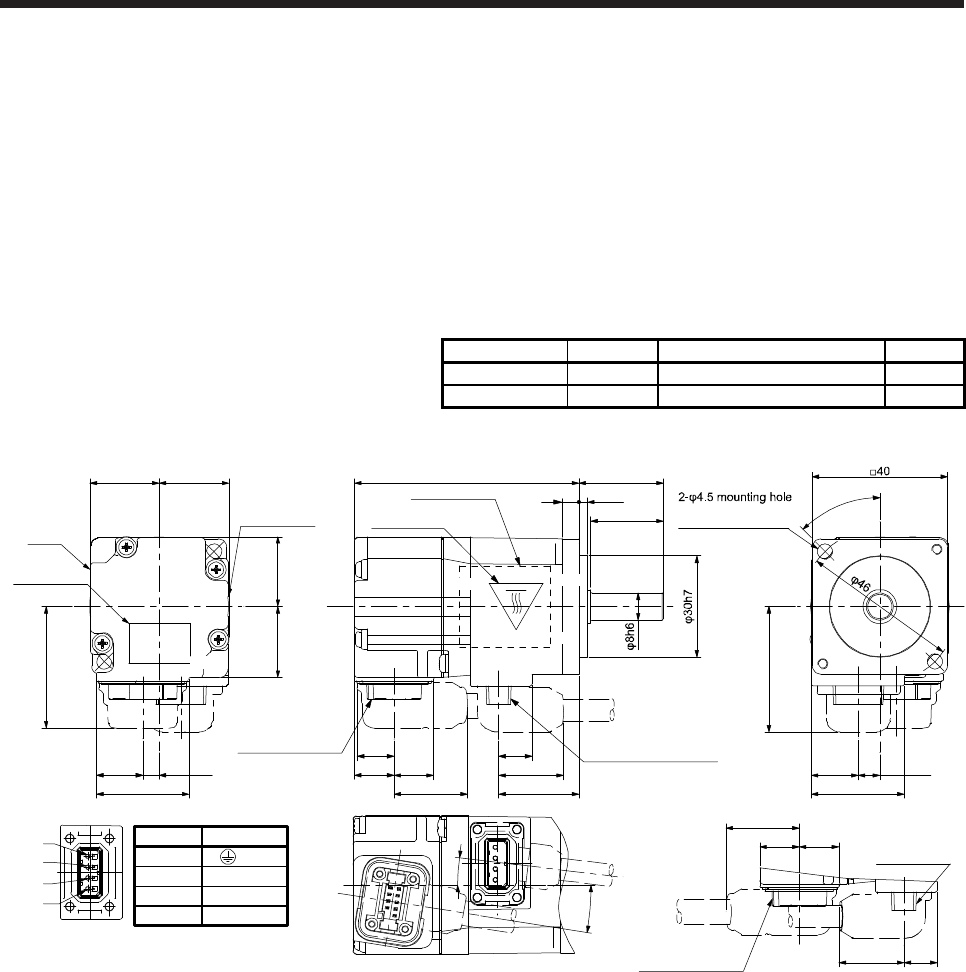
6. HG-MR SERIES/HG-KR SERIES
6 - 15
6.8 Dimensions
Moment of inertia on the table is the value calculated by converting the total value of moment of inertia for
servo motor, reducer, and electromagnetic brake with servo motor shaft.
When running the cables to the load side, take care to avoid interference with the machine. The dimensions
without tolerances are general tolerance.
The outer frame of the reducer is a material surface such as casting. Its actual dimensions may be 1 mm to
3 mm larger than the drawing dimensions. Design the machine-side with allowances.
6.8.1 Standard (without electromagnetic brake and reducer)
Model Output [W] Moment of inertia J [× 10-4 kg•m2] Mass [kg]
HG-MR053 50 0.0162 0.34
HG-KR053 50 0.0450 0.34
[Unit: mm]
45°
Use hexagon socket
head cap screw.
37.1
6.4
27.5
25
2.5
27.4
4.9
9.9
11.7
Bottom
Top
11.7 13.9
20.720.5
Caution plate
21
13.7
21.5
20.7
36
7°
19.2
10.9
21.7
9°
23.8
66.4
Encoder connector
Power supply
connector
19.2
11.711.7
9.9
21.7
Opposite-load side
5
Encoder connector Power supply connector
Caution plate
Motor plate
(Opposite side)
Motor
plate
Caution plate
Bottom
Top Top
Bottom
Power supply connector
1
2
3
4
BC38021C BC38016C
Pin No.
4
3
1
2
Application
W
V
U
(PE)
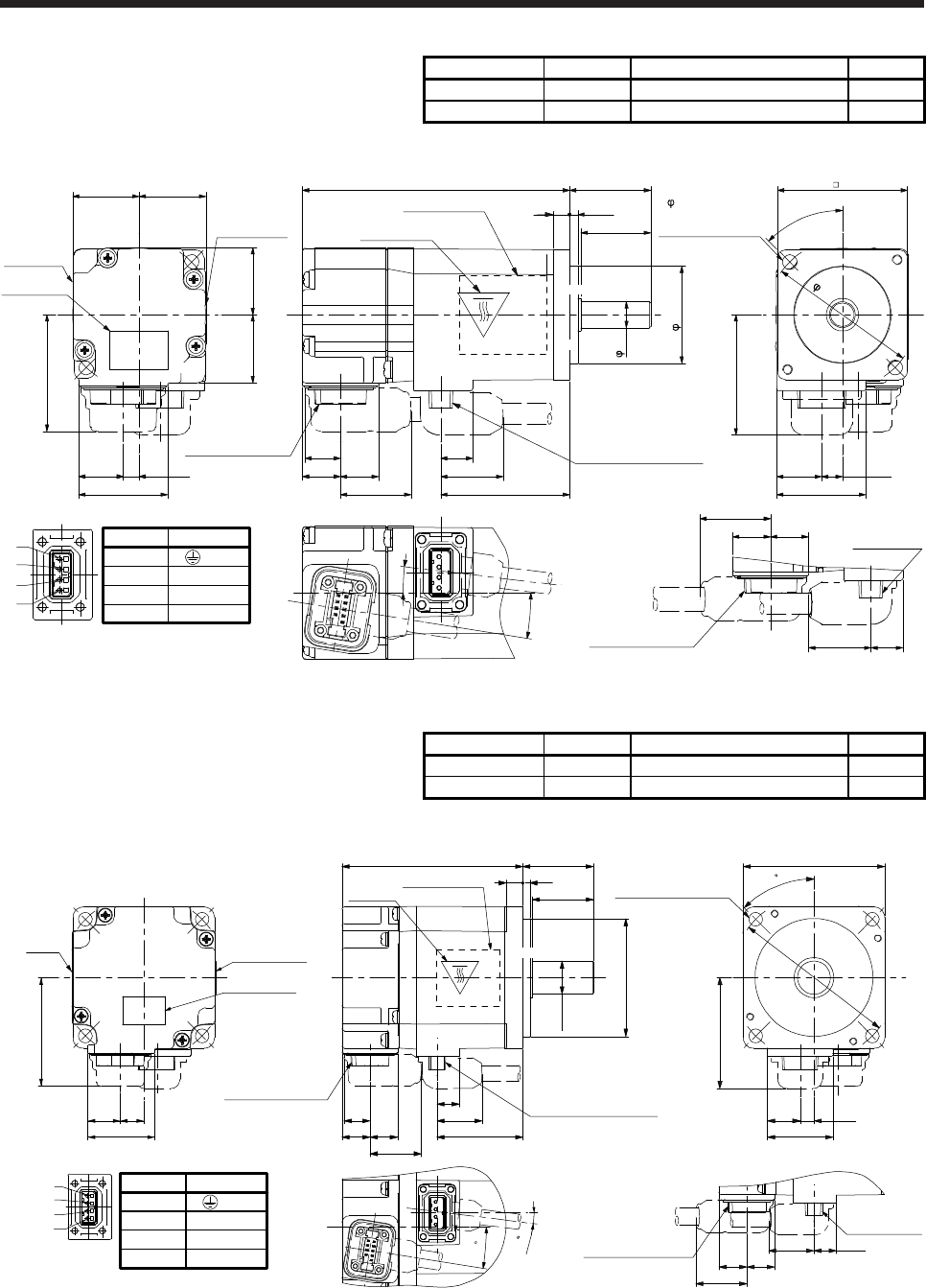
6. HG-MR SERIES/HG-KR SERIES
6 - 16
Model Output [W] Moment of inertia J [× 10-4 kg•m2] Mass [kg]
HG-MR13 100 0.0300 0.54
HG-KR13 100 0.0777 0.54
[Unit: mm]
Power supply connector
Pin No.
4
3
1
2
Application
W
V
U
(PE)
40
45°
37.1
6.4
27.527.4
4.9
Bottom
Top
13.9
20.720.5
Caution plate
21
13.7
20.7
36
Encoder connector
Power supply
connector
19.2
11.711.7
9.9
21.7
Opposite-load side
Motor plate
Caution plate
1
2
3
4
25
2.5
9.9
11.7 11.7
21.5
19.2
10.9
21.7 39.8
82.4
5
Encoder connector Power supply connector
Caution plate
Motor plate
(Opposite side)
Bottom
Top Top
Bottom
BC38022C BC38017C
8h6
30h7
9°
7°
1234
2- 4.5 mounting hole
Use hexagon socket
head cap screw.
46
Model Output [W] Moment of inertia J [× 10-4 kg•m2] Mass [kg]
HG-MR23 200 0.0865 0.91
HG-KR23 200 0.221 0.91
[Unit: mm]
Caution plate
Encoder connector
46
28.4
13.7 10
Caution plate
Motor
plate
Caution
plate
76.6 30
73
26
φ50h7
φ14h6
36.4
19.2
9.5 Power supply connector
21.7
11.7
11.8
10.9
□60
47.1
4-φ5.8 mounting hole
Use hexagon socket
head cap screw.
45
φ70
27.8
13.9 5.9
Opposite-load side
9.5
11.8 11.7
19.2
21.7
Power supply
connector
Encoder connector
BC38023B BC38018B
9
7
Power supply connector
Pin No.
4
3
1
2
Application
W
V
U
(PE)
1
2
3
4
1234
Bottom
Top
Motor plate
(Opposite side)
Bottom
Top
Bottom
Top
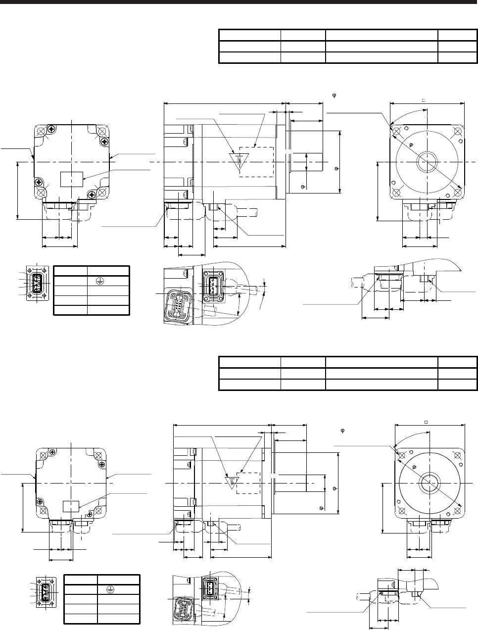
6. HG-MR SERIES/HG-KR SERIES
6 - 17
Model Output [W] Moment of inertia J [× 10-4 kg•m2] Mass [kg]
HG-MR43 400 0.142 1.4
HG-KR43 400 0.371 1.4
[Unit: mm]
1
2
3
4
Caution plate
Bottom
Top
Opposite-load side
60
47.1
27.8
13.9 5.9
46
28.4
13.7 10
9.5
11.8 11.7
19.2
21.7
Caution plate
Power supply
connector
Encoder connector
98.3 30
73
58.111.711.8
10.9 19.2
9.5 Power supply
connector
Encoder connector
21.7
26
Bottom
Top Top
Bottom
Motor plate
(Opposite side)
Caution plate
Motor plate
50h7
14h6
BC38024B BC38019B
4- 5.8 mounting hole
Use hexagon socket
head cap screw.
9°
7°
123
45°
4
70
Power supply connector
Pin No.
4
3
1
2
Application
W
V
U
(PE)
Model Output [W] Moment of inertia J [× 10-4 kg•m2] Mass [kg]
HG-MR73 750 0.586 2.8
HG-KR73 750 1.26 2.8
[Unit: mm]
Opposite-load side
Bottom
Top Top
Bottom
80
112
83
9.510.7
11.8 11.7 19.2
69.6
27.4
13.7 11.5
56
Bottom
Top
40
1214
27.8
57.1
Power supply
connector
Encoder connector
Motor plate
(Opposite side)
Caution plate
Caution plate
Caution plate
Encoder connector
11.811.7
21.7
21.7
36
1
2
3
4
9.519.2
Power supply
connector
Motor plate
7°
7°
70h7
19h6
4- 6.6 mounting hole
Use hexagon socket
head cap screw.
1234
BC38025B BC38020B
45°
90
Power supply connector
Pin No.
4
3
1
2
Application
W
V
U
(PE)
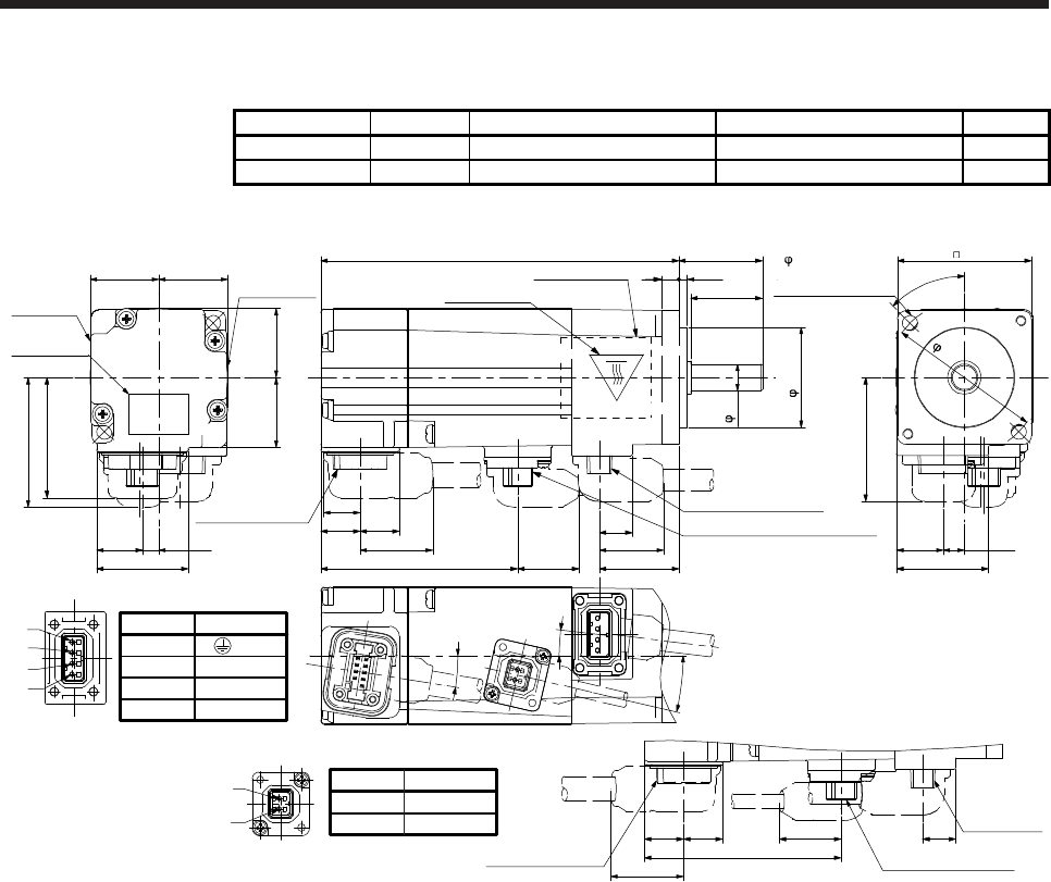
6. HG-MR SERIES/HG-KR SERIES
6 - 18
6.8.2 With an electromagnetic brake
Model Output [W] Brake static friction torque [N•m] Moment of inertia J [× 10-4 kg•m2] Mass [kg]
HG-MR053B 50 0.32 0.0224 0.54
HG-KR053B 50 0.32 0.0472 0.54
[Unit: mm]
40
37.1
6.4
27.5
25
2.5
27.4
4.9
9.911.7
Bottom
Top
11.7
13.9
20.720.5
Caution plate
21
13.7
21.5
20.7
36
19.2
10.9
21.7
23.8
107
Encoder connector
Power supply
connector
11.711.7 9.9
21.7 Opposite-load side
5
Encoder connector Power supply connector
Caution plate
Motor plate
(Opposite side)
Motor plate
Caution plate
Bottom
Top Top
Bottom
1
2
3
4
18.458.8
Electromagnetic brake connector
58.8
18.4
Electromagnetic brake
connector
38.8
2
1
21
2- 4.5mounting hole
Use hexagon socket
head cap screw.
BC38180A BC38175A
45°
46
9°
7°
13°
30h7
8h6
1234
Power supply connector
Pin No.
4
3
1
2
Application
W
V
U
(PE)
Electromagnetic brake connector
Pin No.
1
2
Application
B2
B1
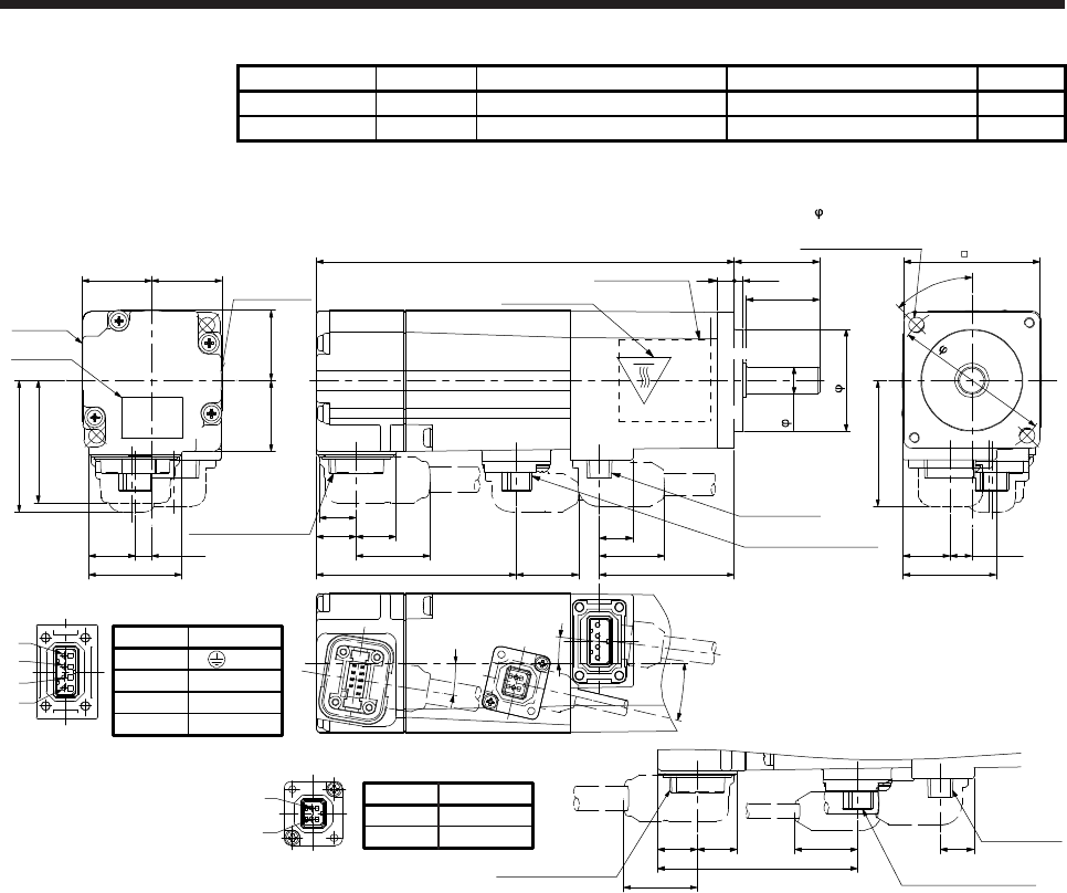
6. HG-MR SERIES/HG-KR SERIES
6 - 19
Model Output [W] Brake static friction torque [N•m] Moment of inertia J [× 10-4 kg•m2] Mass [kg]
HG-MR13B 100 0.32 0.0362 0.74
HG-KR13B 100 0.32 0.0837 0.74
[Unit: mm]
40
37.1
6.4
27.5
25
2.5
27.4
4.9
9.9
11.7
Bottom
Top
11.7
13.9
20.720.5
Caution
plate
21
13.7
21.5
20.7
36
19.2
10.9
21.7
39.8
123
Encoder connector
Power supply
connector
11.711.7 9.9
21.7 Opposite-load side
5
Encoder connector
Power supply
connector
Caution plate
Motor plate
(Opposite side)
Motor
plate
Caution plate
1
2
3
4
18.458.8
Electromagnetic brake
connector
58.8
18.4
Electromagnetic brake
connector
38.8
2
1
2
1
Bottom
Top Top
Bottom
2- 4.5 mounting hole
Use hexagon socket
head cap screw.
9°
7°
13°
30h7
8h6
45°
46
1234
2
1
BC38181A BC38176A
Power supply connector
Pin No.
4
3
1
2
Application
W
V
U
(PE)
Electromagnetic brake connector
Pin No.
1
2
Application
B2
B1
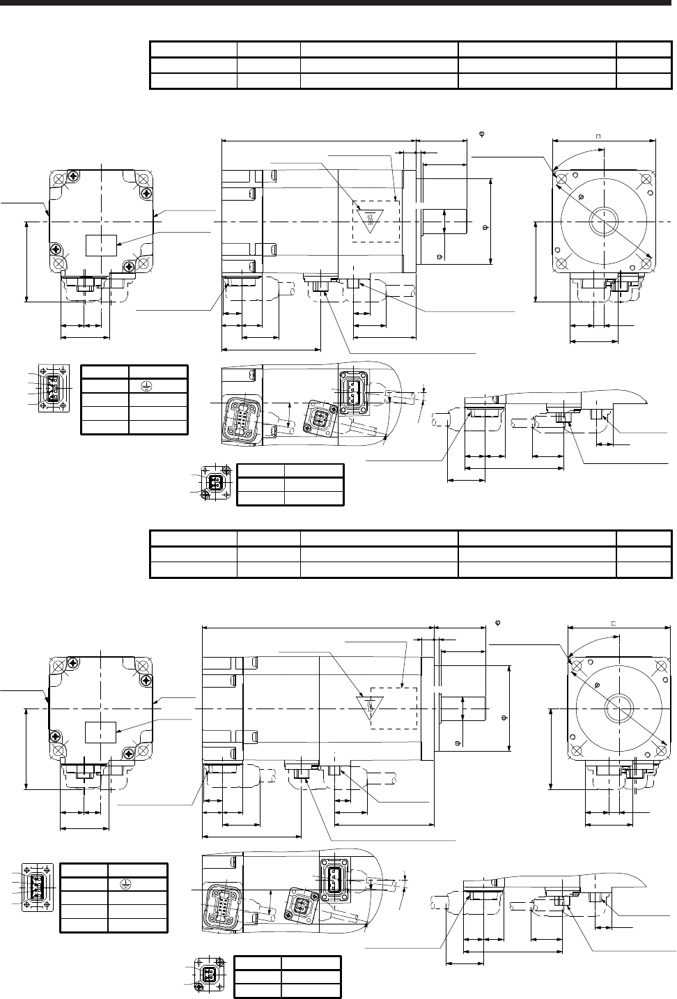
6. HG-MR SERIES/HG-KR SERIES
6 - 20
Model Output [W] Brake static friction torque [N•m] Moment of inertia J [× 10-4 kg•m2] Mass [kg]
HG-MR23B 200 1.3 0.109 1.3
HG-KR23B 200 1.3 0.243 1.3
[Unit: mm]
Bottom
Bottom
1
2
3
4
Caution plate
Bottom
Top
Opposite-load side
113.4 30
73
36.4
11.711.8
10.9
19.2
9.5 Power supply connector
Encoder connector
60
47.1
27.8
13.9 5.9
47.1
28.4
13.7 10
9.5
11.8 11.7
57.8
Caution plate
21.7
26
Top
Caution plate
Top
Motor plate
(Opposite side)
Power supply
connector
Encoder connector
Motor plate
57.8 Electromagnetic brake connector
21.7
18.3 Electromagnetic brake
connector
2
1
21
4- 5.8mounting hole
Use hexagon socket
head cap screw.
9°
7°
13.5°
50h7
14h6
45°
70
1234
BC38182A BC38177A
Power supply connector
Pin No.
4
3
1
2
Application
W
V
U
(PE)
Electromagnetic brake connector
Pin No.
1
2
Application
B2
B1
Model Output [W] Brake static friction torque [N•m] Moment of inertia J [× 10-4 kg•m2] Mass [kg]
HG-MR43B 400 1.3 0.164 1.8
HG-KR43B 400 1.3 0.393 1.8
[Unit: mm]
Bottom
1
2
3
4
Caution
plate
Bottom
Top
Opposite-load side
135.1 30
73
58.1
11.711.8
10.9
19.2
9.5 Power supply
connector
Encoder connector
60
47.1
27.8
13.9 5.9
47.1
28.4
13.7 10
9.5
11.8 11.7
57.8
Caution
plate
21.7
26
Power supply
connector
Encoder connector
Motor plate
57.8 Electromagnetic brake connector
21.7
18.3 Electromagnetic brake
connector
2
1
2
1
Bottom
Top Top
Motor plate
(Opposite side)
Caution plate
4- 5.8mounting hole
Use hexagon socket
head cap screw.
BC38183A BC38178A
9°
7°
13.5°
50h7
14h6
1234
45°
70
Power supply connector
Pin No.
4
3
1
2
Application
W
V
U
(PE)
Electromagnetic brake connector
Pin No.
1
2
Application
B2
B1
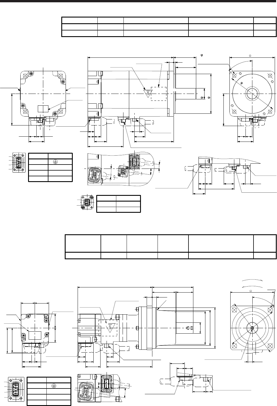
6. HG-MR SERIES/HG-KR SERIES
6 - 21
Model Output [W] Brake static friction torque [N•m] Moment of inertia J [× 10-4 kg•m2] Mass [kg]
HG-MR73B 750 2.4 0.694 3.8
HG-KR73B 750 2.4 1.37 3.8
[Unit: mm]
Power supply connector
Pin No.
4
3
1
2
Application
W
V
U
(PE)
Opposite-load side
Bottom
Top Top
Bottom
80152.3
83
9.510.7
11.8 11.7 19.2
69.627.4
13.7 11.5
56
Bottom
Top
40
1214
27.8
57.1
Power supply
connector
Encoder connector
Motor plate
(Opposite side)
Caution plate
Caution
plate
Caution
plate
Encoder connector
11.8 11.7
63.1
21.7
36
1
2
3
4
9.5
Power supply
connector
Motor plate
63.1 Electromagnetic brake connector
21.7
18.4
Electromagnetic brake
connector
2
1
2
1
4- 6.6mounting hole
Use hexagon socket
head cap screw.
BC38184A BC38179A
7°
7°
7°
70h7
19h6
45°
90
1234
Electromagnetic brake connector
Pin No.
1
2
Application
B2
B1
6.8.3 For general industrial machine with a reducer (without an electromagnetic brake)
Model Output [W] Reducer model
Reduction ratio
(actual
reduction ratio)
Moment of inertia J [× 10-4 kg•m2] Mass [kg]
HG-KR053G1 50 K6505 1/5 (9/44) 0.0820 1.4
[Unit: mm]
27.4
4.9
9.9
11.7 11.7
20.720.5
Caution
plate
21
13.7
20.7
36
19.2
10.9
21.7 67.5
Encoder connector Power supply connector
19.2
11.711.7
9.9
21.7
Opposite-load side
Caution plate
Motor plate
(Opposite side)
Motor
plate Caution plate
Top
110.1
37.1
M4 Screw hole depth 8 6.4
65 4-φ7
1
2
3
4
86.5
34.5 25
60.5
(R3)
Encoder connector
For reverse rotation command
For forward rotation command
Rotation direction
BC40915A
9°
7°
φ60h7
(φ51)
φ48
φ16h6
45°
Power supply connector
Pin No.
4
3
1
2
Application
W
V
U
(PE)
φ75
φ88
Power supply connector
Bottom Bottom
Top
Bottom
Top
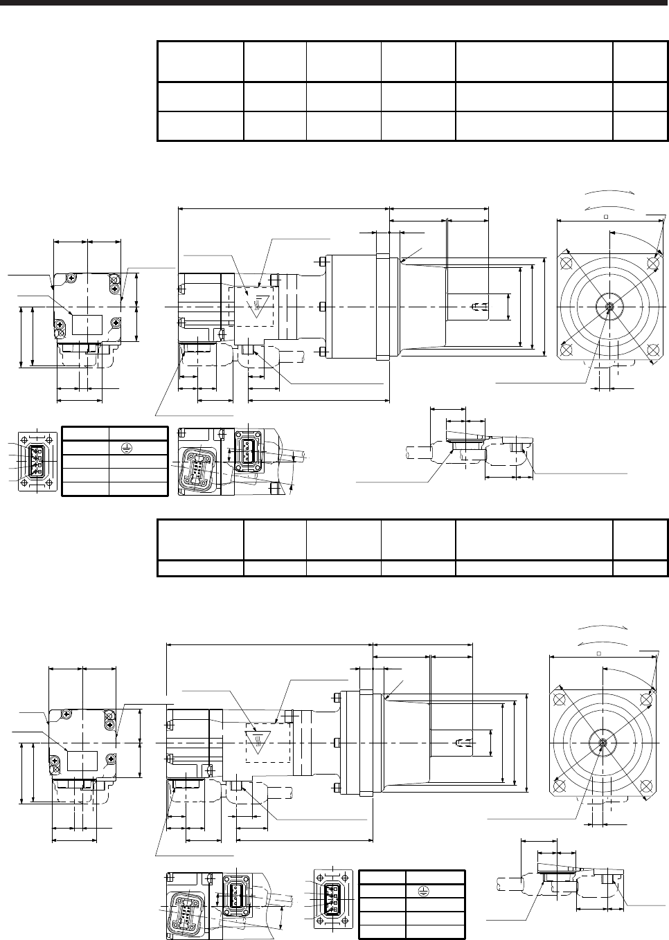
6. HG-MR SERIES/HG-KR SERIES
6 - 22
Model Output [W] Reducer model
Reduction ratio
(actual
reduction ratio)
Moment of inertia J [× 10-4 kg•m2] Mass [kg]
HG-KR053G1 50 K6512 1/12
(49/576) 0.104 1.8
HG-KR053G1 50 K6520 1/20
(25/484) 0.0860 1.8
[Unit: mm]
27.4
4.9
9.9
11.7 11.7
20.720.5
Caution
plate
21
13.7
20.7
36
19.2
10.9
21.7 86.3
Encoder connector
Power supply connector
19.2
11.711.7
9.9
21.7
Power supply connector
Caution plate
Motor plate
(Opposite side)
Motor plate Caution plate
Top
1
2
3
4
128.9
37.1
6.58
60.5
34.5 25
(R3)
M4 Screw hole depth 8 6.4
65 4-φ7
Encoder connector
For reverse rotation command
For forward rotation command
Rotation direction
9°
7°
φ16h6
φ48
(φ51)
φ60h7
φ75
φ88
45°
BC40916A
Opposite-load side
Power supply connector
Pin No.
4
3
1
2
Application
W
V
U
(PE)
Bottom
Top
Bottom Bottom
Top
Model Output [W] Reducer model
Reduction ratio
(actual
reduction ratio)
Moment of inertia J [× 10-4 kg•m2] Mass [kg]
HG-KR13G1 100 K6505 1/5 (9/44) 0.115 1.6
[Unit: mm]
65
BC40917A
27.4
4.9
20.720.5
Caution
plate
21
13.7
20.7
36
Motor
plate
9.9
11.7 11.7 19.2
10.9
21.7
Encoder connector
Power supply connector
Caution plate
Motor plate
(Opposite side)
37.1
1
2
3
4Encoder
connector
Power
supply
connector
19.2
11.711.7
9.9
21.7
Opposite-load side
86.5
34.5 25
60.5
M4 Screw hole depth 8 6.4
126.1
83.5
(R3)
For reverse rotation command
For forward rotation command
Rotation direction
9°
7°
φ60h7
(φ51)
φ48
φ16h6
45°
φ75
φ88
4-φ7
Power supply connector
Pin No.
4
3
1
2
Application
W
V
U
(PE)
Caution plate
Bottom
Top
Top
Bottom
Bottom
Top
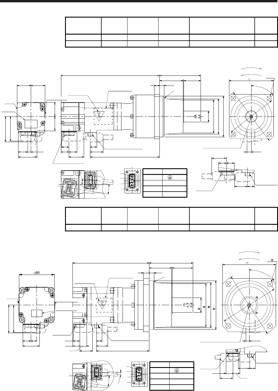
6. HG-MR SERIES/HG-KR SERIES
6 - 23
Model Output [W] Reducer model
Reduction ratio
(actual
reduction ratio)
Moment of inertia J [× 10-4 kg•m2] Mass [kg]
HG-KR13G1 100 K6512 1/12 (49/576) 0.137 2.0
HG-KR13G1 100 K6520 1/20 (25/484) 0.119 2.0
[Unit: mm]
4
3
1
2
27.4
4.9
20.720.5
Caution
plate
21
13.7
20.7
36
Motor
plate
9.9
11.7 11.7 19.2
10.9
21.7 102.3
144.9
Encoder connector
Power supply connector
Caution plate
Motor plate
(Opposite side)
37.1
1
2
3
4Encoder
connector
Power supply
connector
19.2
11.711.7
9.9
21.7
Opposite-load side
6.58
60.5
34.5 25
M4 Screw hole depth 8
6.4
65 4-φ7
(R3)
For reverse rotation command
For forward rotation command
Rotation direction
BC40918A
9°
7°
(φ51)
φ48
φ16h6
φ60h7
45°
φ75
φ88
Power supply connector
Pin No.
4
3
1
2
Application
W
V
U
(PE)
Caution plate
Bottom
Top
Bottom
Bottom
Top
Top
Model Output [W] Reducer model
Reduction ratio
(actual
reduction ratio)
Moment of inertia J [× 10-4 kg•m2] Mass [kg]
HG-KR23G1 200 K9005 1/5 (19/96) 0.375 3.3
[Unit: mm]
Bottom
Top
129.8
89.611.7
11.8
10.9
19.2
9.5
Encoder
connector
46
28.4
13.7 10
21.7
Top
Caution plate
Motor plate
(Opposite side)
Motor
plate
Opposite-load side
9.5
11.8
11.7
19.2
21.7
Power supply
connector
Encoder
connector
47.1
810
74
3538 90 4- 9
M6 Screw hole depth 12 5.9
1
2
3
4
(R3)
For reverse rotation command
For forward rotation command
Rotation direction
82h7
(76)
73
25h6
100
114
45°
9°
7°
BC40919*
Power supply connector
Pin No.
4
3
1
2
Application
W
V
U
(PE)
Caution plate
Caution plate Bottom
Top
Bottom
Power supply connector
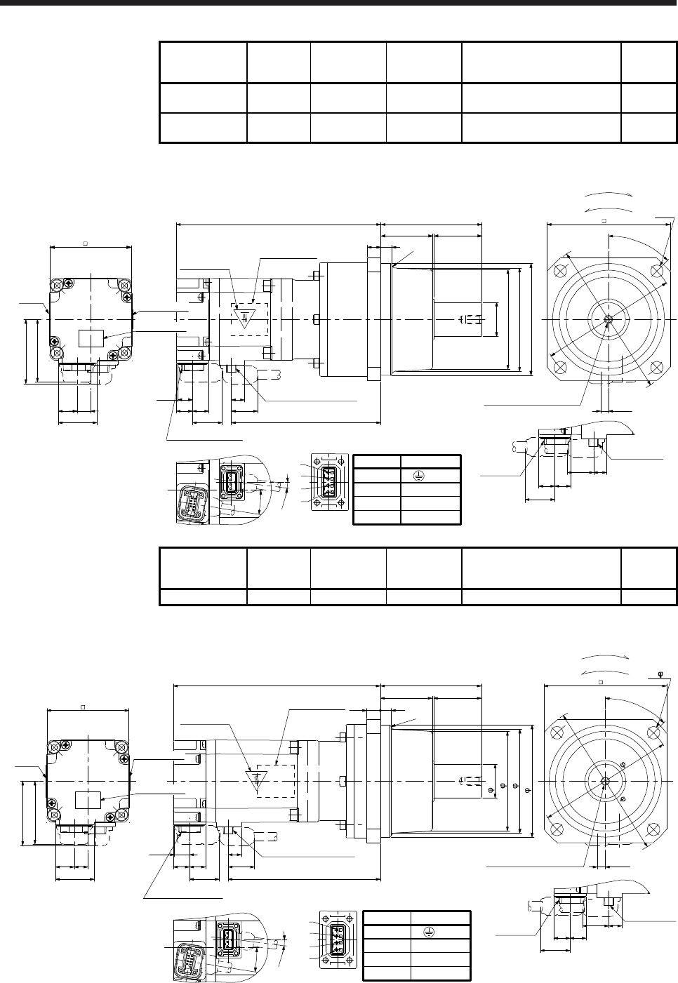
6. HG-MR SERIES/HG-KR SERIES
6 - 24
Model Output [W] Reducer model
Reduction ratio
(actual
reduction ratio)
Moment of inertia J [× 10-4 kg•m2] Mass [kg]
HG-KR23G1 200 K9012 1/12
(961/11664) 0.418 3.9
HG-KR23G1 200 K9020 1/20
(513/9984) 0.391 3.9
[Unit: mm]
Bottom
Top
149.6
109.4
11.711.8
10.9
19.2
9.5 Power supply connector
Encoder connector
46
28.4
13.7 10
21.7
Caution plate
Motor plate
(Opposite side)
Motor
plate
Opposite-load side
9.5
11.811.7
19.2
21.7
Power supply
connector
Encoder
connector
47.1
60
1
2
3
4
90 4-φ9
M6 Screw hole depth 12 5.9
8
10
38 35
74
(R3)
For reverse rotation command
For forward rotation command
Rotation direction
BC40920A
9°
7°
φ82h7
(φ75)
φ72
φ25h6
φ100
φ114
45°
V
U
Power supply connector
Pin No.
4
3
1
2
Application
W
V
U
(PE)
Caution plate
Caution plate Bottom
Bottom
Top
Top
Model Output [W] Reducer model
Reduction ratio
(actual
reduction ratio)
Moment of inertia J [× 10-4 kg•m2] Mass [kg]
HG-KR43G1 400 K9005 1/5 (19/96) 0.525 3.7
[Unit: mm]
1
2
3
4
Bottom
Top
Opposite-load side
46
28.4
13.7 10
9.5
11.811.7
19.2
21.7
Power supply
connector
Encoder
connector
151.5
111.3
11.711.8
10.9
19.2
9.5 Power supply connector
Encoder connector
Bottom
Top
Motor plate
(Opposite side)
Caution plate
Motor
plate
810
74
3538
47.1
60
21.7
90 4- 9
M6 Screw hole depth 12 5.9
(R3)
For reverse rotation command
For forward rotation command
Rotation direction
9°
7°
82h7
(76)
73
25h6
100
114
45°
4
3
1
2
BC40903*
Power supply connector
Pin No.
4
3
1
2
Application
W
V
U
(PE)
Caution plate
Caution plate
Top
Bottom
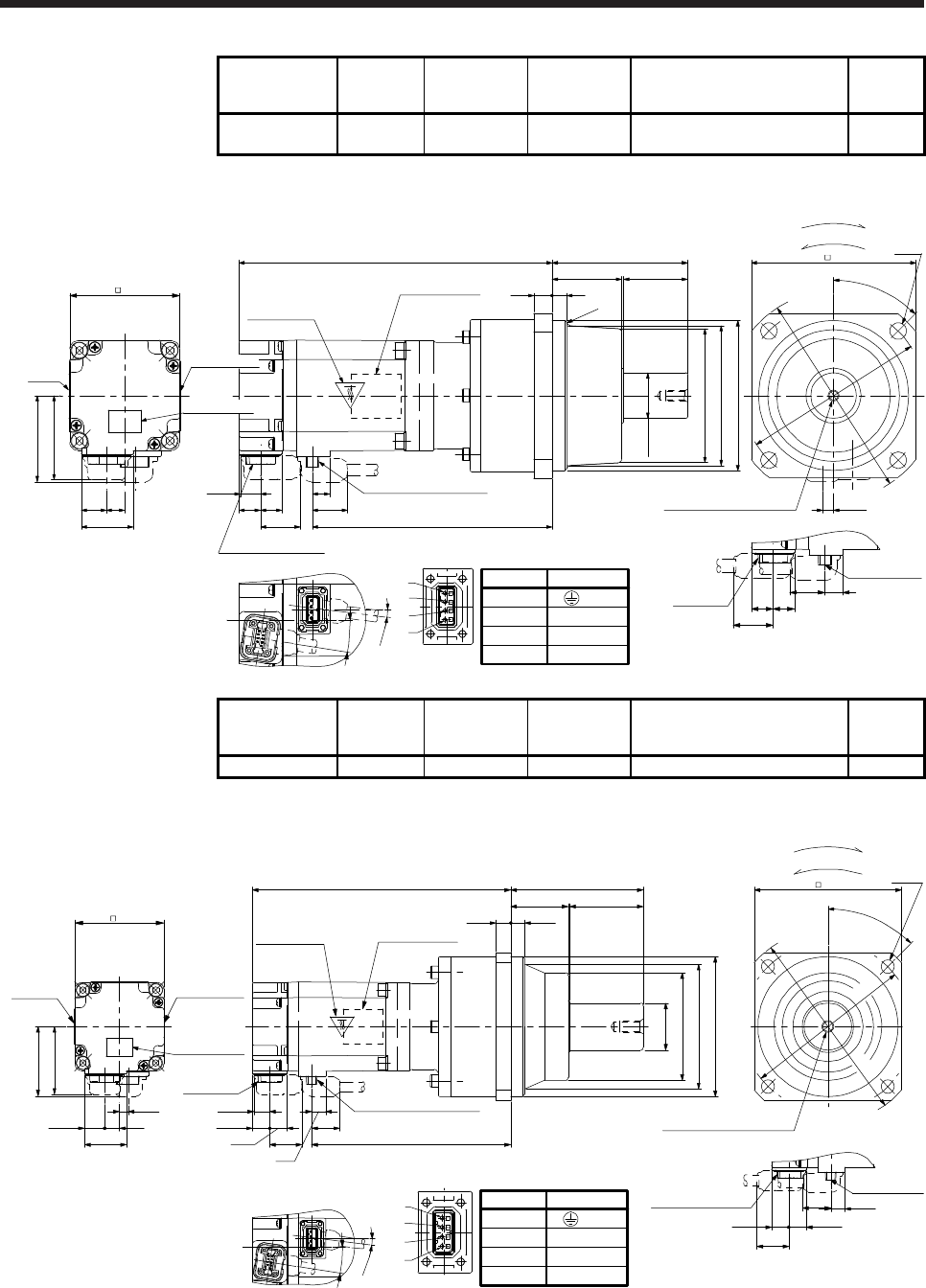
6. HG-MR SERIES/HG-KR SERIES
6 - 25
Model Output [W] Reducer model
Reduction ratio
(actual
reduction ratio)
Moment of inertia J [× 10-4 kg•m2] Mass [kg]
HG-KR43G1 400 K9012 1/12
(961/11664) 0.568 4.3
[Unit: mm]
1
2
3
4
Bottom
Top
Opposite-load side
46
28.4
13.7 10
9.5
11.811.7
19.2
21.7
Power supply
connector
Encoder
connector
171.3
131.1
11.711.8
10.9
19.2
9.5 Power supply connector
Encoder connector
Bottom
Top
Motor plate
(Opposite side)
Caution plate
Motor
plate
810
74
3538
47.1
60
21.7
90 4-φ9
M6 Screw hole depth 12 5.9
(R3)
For reverse rotation command
For forward rotation command
Rotation direction
9°
7°
φ82h7
(φ75)
φ72
φ25h6
φ100
φ114
45°
BC40904A
Power supply connector
Pin No.
4
3
1
2
Application
W
V
U
(PE)
Caution plate
Caution plate
Top
Bottom
Model Output [W] Reducer model
Reduction ratio
(actual
reduction ratio)
Moment of inertia J [× 10-4 kg•m2] Mass [kg]
HG-KR43G1 400 K10020 1/20 (7/135) 0.881 5.4
[Unit: mm]
60
1
2
3
4
Caution plate
Bottom
Opposite-load side
46
28.4
13.7 10
9.5
11.8 11.7
19.2
21.7
Caution plate
Power supply
connector
Encoder connector
175.3
135.111.7
11.8
10.9
19.2
9.5
Power supply connector
Encoder
connector
Top
Motor plate
(Opposite side)
Caution plate
Motor plate
47.1
90
50
9.5
39
10
21.7
M8 Screw hole depth 16
100 4-φ9
5.9
For reverse rotation command
For forward rotation command
Rotation direction
BC40905A
9°
7°
V
φ95h7
φ83
φ73
φ32h6
φ115
φ132
45°
Power supply connector
Pin No.
4
3
1
2
Application
W
V
U
(PE)
Top
Top
Bottom
Bottom
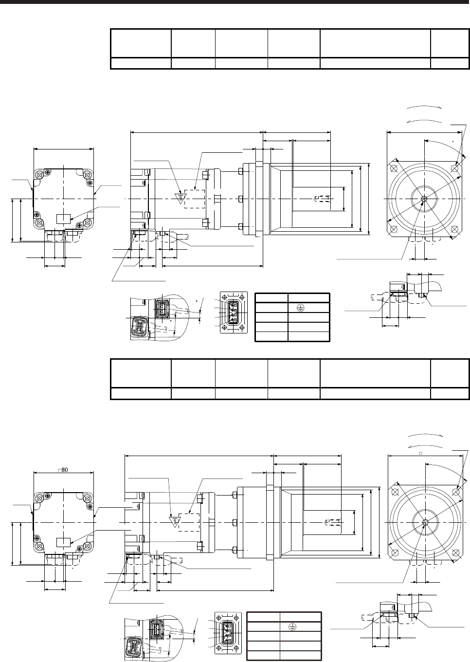
6. HG-MR SERIES/HG-KR SERIES
6 - 26
Model Output [W] Reducer model
Reduction ratio
(actual
reduction ratio)
Moment of inertia J [× 10-4 kg•m2] Mass [kg]
HG-KR73G1 750 K10005 1/5 (1/5) 1.68 6.0
[Unit: mm]
27.4
13.7 11.5
56
Bottom
Top
Caution
plate
Caution
plate
Motor
plate
57.1
□80
Top
177
9.510.7
11.8 19.2
134.6
Power supply connector
Motor plate
(Opposite side)
Caution plate
Bottom Bottom
Top
11.7
Encoder connector
21.7
90
50
10
39
10
φ95h7
φ81
φ73
φ32h6
12
□100
4-φ9
M8 Screw hole depth 16
For reverse rotation command
For forward rotation command
Rotation direction
45
φ115
φ132
Opposite-load side
Encoder
connector
11.8 11.7
21.7
9.5
19.2
Power supply
connector
Power supply connector
Pin No.
4
3
1
2
Application
W
V
U
(PE)
BC40906A
7
7
1
2
3
4
Model Output [W] Reducer model
Reduction ratio
(actual
reduction ratio)
Moment of inertia J [× 10-4 kg•m2] Mass [kg]
HG-KR73G1 750 K10012 1/12 (7/87) 2.35 7.1
[Unit: mm]
90
50
9.5
39
10
Opposite-load side
Bottom
Top Top
199
9.510.7
11.8
11.7
19.2
156.6
27.4
13.7 11.5
56
Bottom
Power supply connector
Encoder connector
Motor plate
(Opposite side)
Caution plate
Encoder
connector
11.8 11.7
21.7
21.7 9.5
19.2
Power supply
connector
Motor
plate
12
100 4- φ9
57.1
M8 Screw hole depth 16
1
2
3
4
For reverse rotation command
For forward rotation command
Rotation direction
BC40907A
φ95h7
φ83
φ73
φ32h6
45°
φ115
φ132
7°
7°
Power supply connector
Pin No.
4
3
1
2
Application
W
V
U
(PE)
Caution plate
Top
Caution plate
Bottom
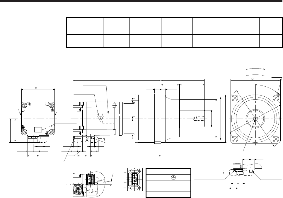
6. HG-MR SERIES/HG-KR SERIES
6 - 27
Model Output [W] Reducer model
Reduction ratio
(actual
reduction ratio)
Moment of inertia J [× 10-4 kg•m2] Mass [kg]
HG-KR73G1 750 K12020 1/20
(625/12544) 2.41 10
[Unit: mm]
105.5
60
11.5
44.5
15
Opposite-load side
Bottom
Top Top
212
9.510.7
11.8
11.7
19.2
169.6
27.4
13.7 11.5
56
Motor plate
(Opposite side)
Caution plate
Encoder connector
11.8 11.7
21.7
21.7
9.5
19.2
Power supply
connector
Motor
plate
120 4-φ14
80
57.1
M10 Screw hole depth 20
12
Encoder connector
1
2
3
4
For reverse rotation command
For forward rotation command
Rotation direction
φ115h7
φ98
φ90
φ40h6
45°
φ140
φ162
7°
7°
BC40908A
Power supply connector
Pin No.
4
3
1
2
Application
W
V
U
(PE)
Caution plate
Caution plate
Bottom
Power supply connector
Bottom
Top
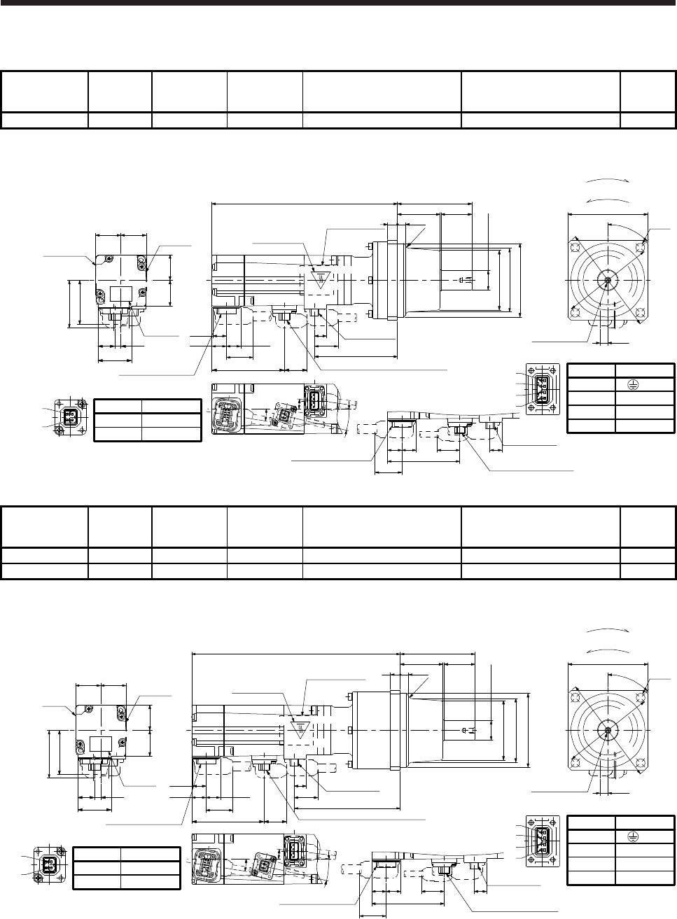
6. HG-MR SERIES/HG-KR SERIES
6 - 28
6.8.4 For general industrial machine with a reducer (with an electromagnetic brake)
Model Output [W] Reducer model
Reduction ratio
(actual
reduction ratio)
Brake static friction torque [N•m] Moment of inertia J [× 10-4 kg•m2] Mass [kg]
HG-KR053BG1 50 K6505 1/5 (9/44) 0.32 0.0840 1.6
[Unit: mm]
27.4
4.9
9.9
21.7
20.720.5
Caution
plate
21
13.7
20.7
36
19.2
10.9
67.5
Power supply
connector
Caution plate
Motor plate
150.7
38.8
φ16h6
φ48
(φ51)
φ60h7
8 6.5
34.5 25
60.5
(R3)
Encoder connector Electromagnetic brake connector
18.458.8
7°
13°
9°
6.4
4-φ7
45°
M4 Screw hole
depth 8
φ75
φ88
Encoder connector
Power supply
connector
11.711.7 9.9
21.7 Opposite-load side
58.8
18.4
Electromagnetic brake
connector
2
1Pin No.
1
2
Application
B2
B1
Electromagnetic brake connector
BC41085A
1
2
3
4
Pin No.
4
3
1
2
Application
W
V
U
(PE)
Power supply connector
11.7 11.7
□65
Bottom
Top
Caution
plate
Motor plate
(Opposite side)
Bottom
Top
Bottom
Top
For reverse rotation command
For forward rotation command
Rotation direction
Model Output [W] Reducer model
Reduction ratio
(actual
reduction ratio)
Brake static friction torque [N•m] Moment of inertia J [× 10-4 kg•m2] Mass [kg]
HG-KR053BG1 50 K6512 1/12 (49/576) 0.32 0.106 2.0
HG-KR053BG1 50 K6520 1/20 (25/484) 0.32 0.0880 2.0
[Unit: mm]
20.720.5
21 20.7
36
Motor
plate
Caution
plate
38.8
27.4
4.9
Caution
plate
13.7
9.9
21.7
19.2
10.9
86.3
Power supply
connector
Caution plate
169.5
φ16h6
φ48
(φ51)
φ60h7
8 6.5
34.5 25
60.5
(R3)
Encoder connector Electromagnetic brake connector
18.458.8
7°
13°
9°
6.4
4-φ7
45°
M4 Screw hole
depth 8
φ75
φ88
Encoder connector
Power supply
connector
11.711.7 9.9
21.7 Opposite-load side
58.8
18.4
Electromagnetic brake
connector
2
1Pin No.
1
2
Application
B2
B1
Electromagnetic brake connector
Pin No.
4
3
1
2
Application
W
V
U
(PE)
Power supply connector
1
2
3
4
BC41086A
11.7 11.7
□65
Bottom
Top
Motor plate
(Opposite side)
Bottom
Top
Top
Bottom
For reverse rotation command
For forward rotation command
Rotation direction
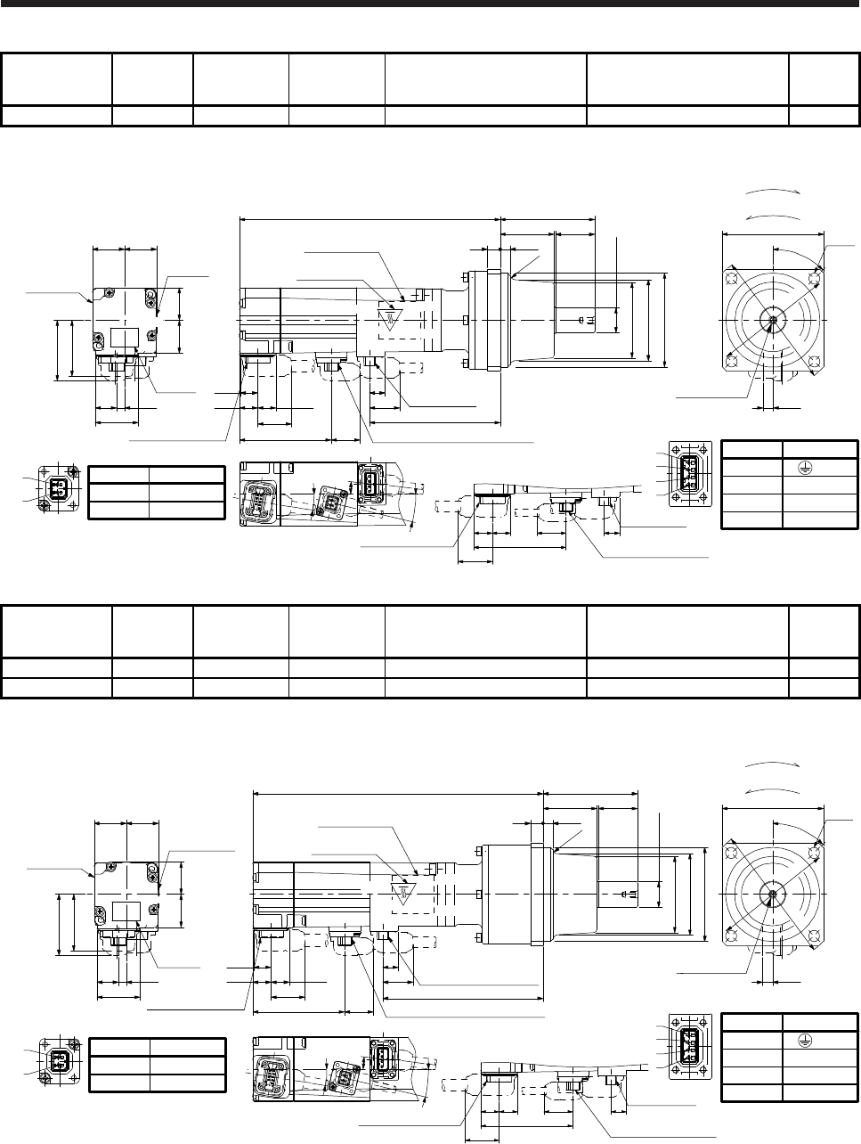
6. HG-MR SERIES/HG-KR SERIES
6 - 29
Model Output [W] Reducer model
Reduction ratio
(actual
reduction ratio)
Brake static friction torque [N•m] Moment of inertia J [× 10-4 kg•m2] Mass [kg]
HG-KR13BG1 100 K6505 1/5 (9/44) 0.32 0.121 1.8
[Unit: mm]
27.4
4.9
Caution
plate
21
13.7
20.7
36
Motor plate
Caution
plate
38.8
20.720.5
11.7 11.7
10.9
21.7
Encoder connector 18.458.8
9.9
19.2
83.5
166.7
Power supply
connector
Caution plate
Electromagnetic brake connector
φ60h7
φ48
6.58
60.5
34.5 25
(φ51)
φ16h6
(R3)
M4 Screw hole
depth 8 6.4
45°
4-φ7
□65
φ75
φ88
Pin No.
4
3
1
2
Application
W
V
U
(PE)
Power supply connector
1
2
3
4
BC41087A
Power supply
connector
11.711.7 9.9
21.7 Opposite-load side
58.8
18.4
Electromagnetic brake
connector
Encoder connector
7°
13°
9°
Pin No.
1
2
Application
B2
B1
Electromagnetic brake connector
2
1
Bottom
Top
Motor plate
(Opposite side)
For reverse rotation command
For forward rotation command
Rotation direction
Bottom
Top
Top
Bottom
Model Output [W] Reducer model
Reduction ratio
(actual
reduction ratio)
Brake static friction torque [N•m] Moment of inertia J [× 10-4 kg•m2] Mass [kg]
HG-KR13BG1 100 K6512 1/12 (49/576) 0.32 0.143 2.2
HG-KR13BG1 100 K6520 1/20 (25/484) 0.32 0.125 2.2
[Unit: mm]
27.4
4.9
Caution
plate
21
13.7
20.7
36
Encoder connector
Motor plate
Caution plate
38.8
20.720.5
Pin No.
1
2
Application
B2
B1
Electromagnetic brake connector
2
1
185.5
9.9
19.2
102.3
Power supply connector
Electromagnetic brake connector
11.7 11.7
10.9
21.7
18.458.8
6.58
60.5
34.5 25
φ60h7
(φ51)
φ16h6
φ48
(R3)
M4 Screw hole
depth 8 6.4
45°
4-φ7
□65
φ75
φ88
Pin No.
4
3
1
2
Application
W
V
U
(PE)
Power supply connector
1
2
3
4
BC41088A
Encoder connector
Power supply
connector
11.711.7 9.9
21.7 Opposite-load side
58.8
18.4
Electromagnetic brake
connector
7°
13°
9°
Bottom
Top
Motor plate
(Opposite side)
Caution plate
For reverse rotation command
For forward rotation command
Rotation direction
Bottom
Bottom
Top
Top
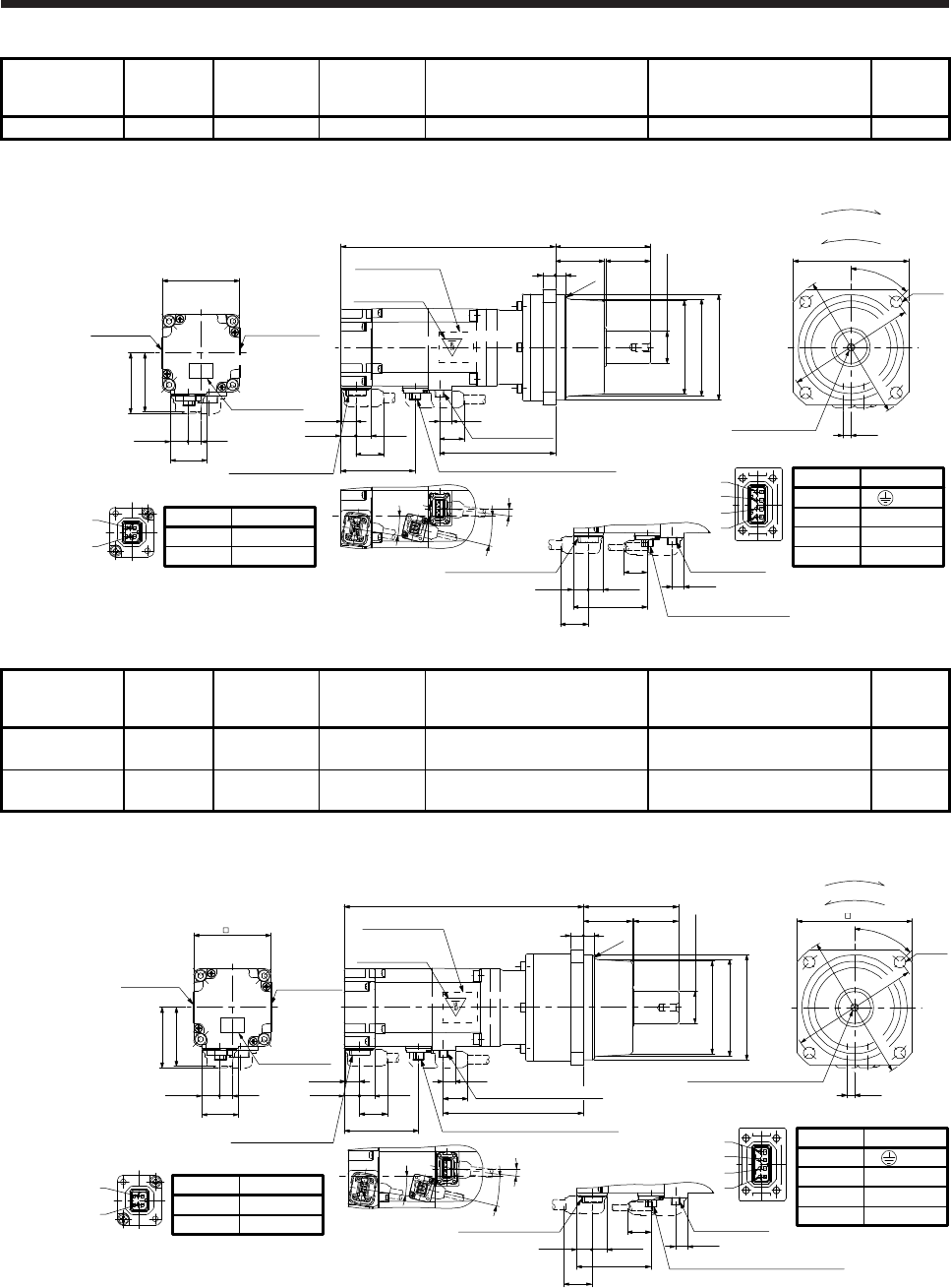
6. HG-MR SERIES/HG-KR SERIES
6 - 30
Model Output [W] Reducer model
Reduction ratio
(actual
reduction ratio)
Brake static friction torque [N•m] Moment of inertia J [× 10-4 kg•m2] Mass [kg]
HG-KR23BG1 200 K9005 1/5 (19/96) 1.3 0.397 3.7
[Unit: mm]
Caution plate
47.1
28.4
13.7 10
Caution plate
Caution plate
Motor plate
□60
46
11.711.8
10.9
Encoder connector
21.7
57.8
166.6
89.6
19.2
9.5
Electromagnetic brake connector
38
(R3)
10 8
φ25h6
φ73
φ82h7
35
74
(φ76)
9°
7°
13.5°
Opposite-load side
9.5
11.8 11.7
57.8
Power supply
connector
Encoder connector
21.7
18.3
Electromagnetic brake
connector
Pin No.
4
3
1
2
Application
W
V
U
(PE)
Power supply connector
BC41089*
1
2
3
4
5.9
M6 Screw hole
depth 12
φ100
45°
φ114
4-φ9
□90
2
1Pin No.
1
2
Application
B2
B1
Electromagnetic brake connector
Top
Power supply
connector
Motor plate
(Opposite side)
For reverse rotation command
For forward rotation command
Rotation direction
Bottom
Top
Bottom
Top
Bottom
Model Output [W] Reducer model
Reduction ratio
(actual
reduction ratio)
Brake static friction torque [N•m] Moment of inertia J [× 10-4 kg•m2] Mass [kg]
HG-KR23BG1 200 K9012 1/12
(961/11664) 1.3 0.440 4.3
HG-KR23BG1 200 K9020 1/20
(513/9984) 1.3 0.413 4.3
[Unit: mm]
60
90
186.4
109.4
11.711.8
10.9
19.2
9.5
Encoder connector
21.7
Caution plate
Motor plate
(Opposite side)
57.8 Electromagnetic brake connector
φ25h6
φ72
φ82h7
810
38 35
74
(φ75)
(R3)
Bottom
47.1
28.4
13.7 10
Caution plate
46
Caution plate
Motor plate
9°
7°
13.5°
Opposite-load side
9.5
11.8 11.7
57.8
Power supply
connector
Encoder connector
21.7
18.3
Electromagnetic brake connector
φ100
45°
5.9
φ114
4-φ9
M6 Screw hole depth 12
1
2
3
4
2
1
Pin No.
4
3
1
2
Application
W
V
U
(PE)
Power supply connector
Pin No.
1
2
Application
B2
B1
Electromagnetic brake connector
BC41090A
For reverse rotation command
For forward rotation command
Rotation direction
Power supply connector
Top
Top
Bottom
Top
Bottom
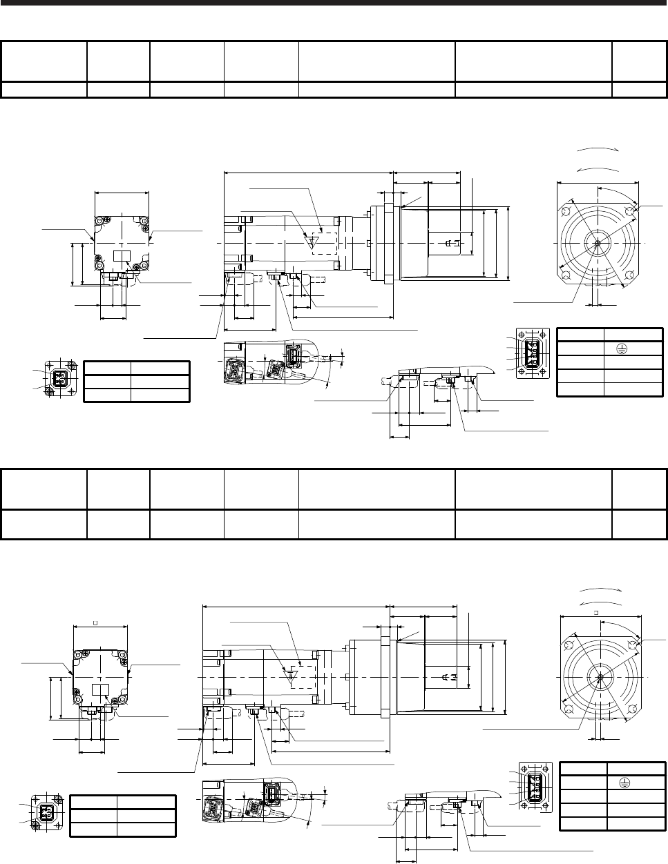
6. HG-MR SERIES/HG-KR SERIES
6 - 31
Model Output [W] Reducer model
Reduction ratio
(actual
reduction ratio)
Brake static friction torque [N•m] Moment of inertia J [× 10-4 kg•m2] Mass [kg]
HG-KR43BG1 400 K9005 1/5 (19/96) 1.3 0.547 4.1
[Unit: mm]
Caution plate
47.1
28.4
13.7 10
Caution plate
Motor plate
□60
46
Pin No.
1
2
Application
B2
B1
Electromagnetic brake connector
2
1
111.3
11.711.8
10.9
19.2
9.5 Power supply
connector
Encoder connector
21.7
57.8 Electromagnetic brake connector
188.3
Caution plate
9°
7°
13.5°
φ25h6
810
38 35
74
(R3)
φ73
φ82h7
(φ76)
φ100
5.9
φ114
4-φ9
M6 Screw hole
depth 12
45°
□90
Pin No.
4
3
1
2
Application
W
V
U
(PE)
Power supply connector
1
2
3
4
Opposite-load side
9.5
11.8 11.7
57.8
Power supply
connector
Encoder connector
21.7
18.3
Electromagnetic brake
connector
BC41091*
Motor plate
(Opposite side)
Top
Top
Bottom
Top
For reverse rotation command
For forward rotation command
Rotation direction
Bottom
Bottom
Model Output [W] Reducer model
Reduction ratio
(actual
reduction ratio)
Brake static friction torque [N•m] Moment of inertia J [× 10-4 kg•m2] Mass [kg]
HG-KR43BG1 400 K9012 1/12
(961/11664) 1.3 0.590 4.7
[Unit: mm]
60
90
208.1
Bottom
Top
Motor plate
(Opposite side)
Caution plate
9°
7°
131.1
11.711.8
10.9
19.2
9.5
Power supply connector
Encoder connector
21.7
57.8
13.5°
810
74
3538
φ25h6
φ72
φ82h7
(R3)
(φ75)
Caution plate
Bottom
47.1
28.4
13.7 10
Caution plate
Motor plate
46
φ100
45°
5.9
φ114
4-φ9
M6 Screw hole depth 12
2
1Pin No.
1
2
Application
B2
B1
Electromagnetic brake connector
1
2
3
4
Pin No.
4
3
1
2
Application
W
V
U
(PE)
Power supply connector
Opposite-load side
9.5
11.8 11.7
57.8
Encoder connector
21.7
18.3
Electromagnetic brake connector
Electromagnetic brake connector
BC41092A
For reverse rotation command
For forward rotation command
Rotation direction
Power supply
connector
Top
Top
Bottom
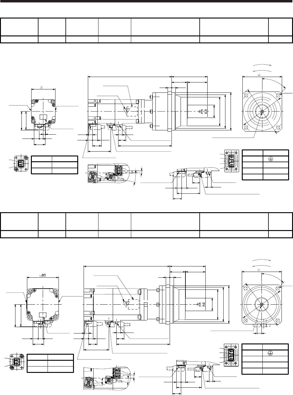
6. HG-MR SERIES/HG-KR SERIES
6 - 32
Model Output [W] Reducer model
Reduction ratio
(actual
reduction ratio)
Brake static friction torque [N•m] Moment of inertia J [× 10-4 kg•m2] Mass [kg]
HG-KR43BG1 400 K10020 1/20 (7/135) 1.3 0.903 5.8
[Unit: mm]
60
100
Caution plate
10
5.9
212.1
Bottom
Top
Motor plate
(Opposite side)
Caution plate
9°
7°
Bottom
135.1
11.711.8
10.9
19.2
9.5
Power supply connector
Encoder connector
47.1
28.4
13.7
Caution plate
21.7
Motor plate
57.8
13.5°
Electromagnetic brake connector
90
50
9.5
39
10
φ32h6
φ73
φ83
φ95h7
46
2
1Pin No.
1
2
Application
B2
B1
Electromagnetic brake connector 1
2
3
4
Pin No.
4
3
1
2
Application
W
V
U
(PE)
Power supply connector
Opposite-load side
9.5
11.8 11.7
57.8
Power supply
connector
Encoder connector
21.7
18.3
Electromagnetic brake connector
BC41093A
For reverse rotation command
For forward rotation command
Rotation direction
φ132
M8 Screw hole depth 16
4-φ9
45°
φ115
Top
Bottom
Top
Model Output [W] Reducer model
Reduction ratio
(actual
reduction ratio)
Brake static friction torque [N•m] Moment of inertia J [× 10-4 kg•m2] Mass [kg]
HG-KR73BG1 750 K10005 1/5 (1/5) 2.4 1.79 7.0
[Unit: mm]
100
2
1Pin No.
1
2
Application
B2
B1
Electromagnetic brake connector
1
2
3
4
Pin No.
4
3
1
2
Application
W
V
U
(PE)
Power supply connector
BC41094A
Bottom
Top Top
Bottom
217.3
Motor plate
(Opposite side)
Caution plate
For reverse rotation command
For forward rotation command
Rotation direction
Opposite-load side
7°
9.5
10.7
11.8 11.7 19.2
134.627.4
13.7 11.5
56
Bottom
Top
Power supply connector
Encoder connector
Caution plate
Caution plate
Encoder connector
11.8 11.7
63.1
21.7
7°
9.5
Power supply
connector
Motor plate
7°
63.1 Electromagnetic brake connector
21.7
18.4
Electromagnetic brake connector
57.1
90
50
10
39
10
φ32h6
φ73
φ81
φ95h7
12
45°
4-φ9
φ115
φ132
M8 Screw hole depth 16
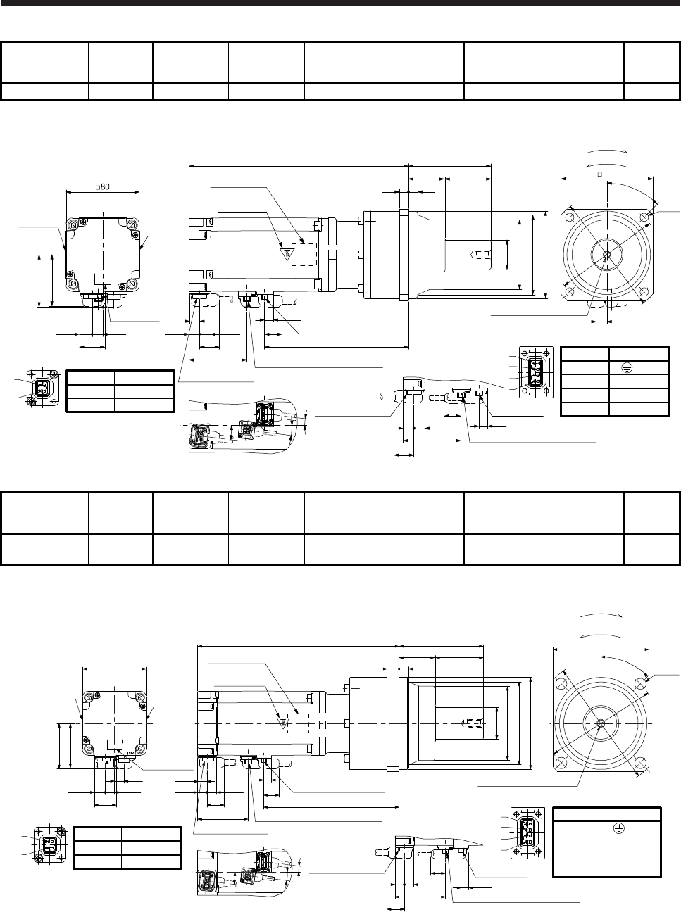
6. HG-MR SERIES/HG-KR SERIES
6 - 33
Model Output [W] Reducer model
Reduction ratio
(actual
reduction ratio)
Brake static friction torque [N•m] Moment of inertia J [× 10-4 kg•m2] Mass [kg]
HG-KR73BG1 750 K10012 1/12 (7/87) 2.4 2.46 8.1
[Unit: mm]
100
Bottom
Top Top
239.3
Motor plate
(Opposite side)
Caution plate
For reverse rotation command
For forward rotation command
Rotation direction
Opposite-load side
7°
9.5
10.7
11.8 11.7 19.2
156.6
27.4
13.7 11.5
56
Bottom
Top
Power supply connector
Encoder connector
Caution plate
Encoder connector
11.8 11.7
63.1
21.7
7°
9.5
Power supply
connector
Motor plate
7°
63.1 Electromagnetic brake connector
21.7
18.4
Electromagnetic brake connector
57.1
90
50
9.5
39
10
φ32h6
φ73
φ83
φ95h7
12
45°
4-φ9
φ115
φ132
M8 Screw hole depth 16
1
2
3
4
Pin No.
4
3
1
2
Application
W
V
U
(PE)
Power supply connector
2
1Pin No.
1
2
Application
B2
B1
Electromagnetic brake connector
BC41095A
Caution plate
Bottom
Model Output [W] Reducer model
Reduction ratio
(actual
reduction ratio)
Brake static friction torque [N•m] Moment of inertia J [× 10-4 kg•m2] Mass [kg]
HG-KR73BG1 750 K12020 1/20
(625/12544) 2.4 2.52 11
[Unit: mm]
Motor plate
(Opposite side)
Caution plate
Bottom
Caution plate
Caution
plate
Motor
plate
Top
27.4
13.7 11.5
56
57.1
□80
12 10.7
11.7
169.6
Power supply connector
Encoder connector
21.7
63.1 Electromagnetic brake connector
252.3
9.5
11.8 19.2
Bottom Bottom
7°
7°
105.5
60
11.5
44.5
15
Encoder connector
Opposite-load side
Power supply
connector
Electromagnetic brake connector
□120
4-φ14
M10 Screw hole depth 20
BC41096A
45°
φ
140
φ
162
9.5
φ40h6
φ90
φ98
φ115h7
11.8 11.7
63.1
21.7
18.4
For reverse rotation command
For forward rotation command
Rotation direction
1
2
3
4
Pin No.
1
2
Application
B2
B1
Electromagnetic brake connector
2
1
Pin No.
4
3
1
2
Application
W
V
U
(PE)
Power supply connector
Top
Top
7°
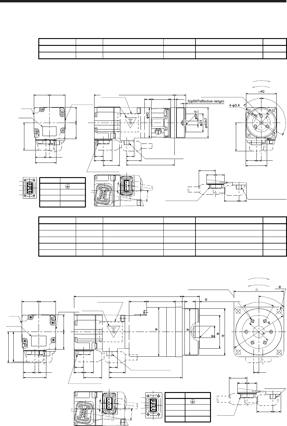
6. HG-MR SERIES/HG-KR SERIES
6 - 34
6.8.5 With flange-output type reducer for high precision applications, flange mounting (without an
electromagnetic brake)
Model Output [W] Reducer model Reduction ratio Moment of inertia J [× 10-4 kg•m2] Mass [kg]
HG-KR053G5 50 HPG-11B-05-F0ADG-S 1/5 0.0485 0.55
HG-KR053G5 50 HPG-11B-09-F0ADG-S 1/9 0.0475 0.56
[Unit: mm]
45°
6.4
27.5
15+0.25
-0.20
2.5
27.4
4.9 9.9
11.7
Bottom
11.7 13.9
20.720.5
Caution
plate
21
13.7
20.7
36
7°
19.2
10.9
21.7
9°
63.3
105.9
5
Encoder connector
Caution plate
(Opposite side)
Motor
plate Caution plate
Top
C0.5
120°
25.5 3-M4 Screw hole depth 6
9
For reverse rotation command
For forward rotation command
Rotation direction
Encoder connector Power supply connector
19.2
11.711.7
9.9
21.7
Opposite-load side BC40937*
Power supply connector
1
2
3
4
37.1
Motor plate
Power supply connector
Pin No.
4
3
1
2
Application
W
V
U
(PE)
Bottom
Top
Bottom
Top
Model Output [W] Reducer model Reduction ratio Moment of inertia J [× 10-4 kg•m2] Mass [kg]
HG-KR053G5 50 HPG-14A-05-F0CBJS-S 1/5 0.113 1.1
HG-KR053G5 50 HPG-14A-11-F0CBKS-S 1/11 0.105 1.2
HG-KR053G5 50 HPG-14A-21-F0CBKS-S 1/21 0.0960 1.2
HG-KR053G5 50 HPG-14A-33-F0CBLS-S 1/33 0.0900 1.2
HG-KR053G5 50 HPG-14A-45-F0CBLS-S 1/45 0.0900 1.2
[Unit: mm]
27.4
4.9
9.9
11.7
Bottom
11.7
20.720.5
Caution
plate
21
13.7
20.7
37.1
19.2
10.9
21.7 87.8
Encoder
connector
Power supply
connector
19.2
11.711.7
9.9
21.7
Opposite-load side
Power supply connector
Caution plate
Motor plate
(Opposite side)
Motor
plate
Top
3
821 35
C0.5
130.4
6-M4 Screw hole depth 7 60 4- 5.5
6.4
36
Encoder connector
1
2
3
4
For reverse rotation command
For forward rotation command
Rotation direction
59
55.5
14H7
40
56h7
45°
30
70
BC38196*
9°
7°
Power supply connector
Pin No.
4
3
1
2
Application
W
V
U
(PE)
60°
21+0.4
-0.5
Caution plate
Top
Bottom Bottom
Top
5( 14H7effective range)
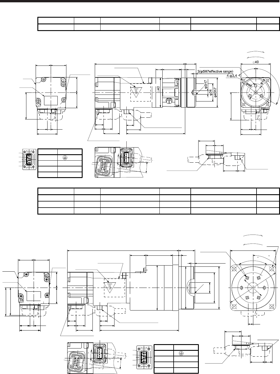
6. HG-MR SERIES/HG-KR SERIES
6 - 35
Model Output [W] Reducer model Reduction ratio Moment of inertia J [× 10-4 kg•m2] Mass [kg]
HG-KR13G5 100 HPG-11B-05-F0ADG-S 1/5 0.0812 0.75
[Unit: mm]
27.4
4.9
Bottom
20.720.5
Caution
plate
21
13.7
20.7
36
Motor
plate
Caution plate
15+0.25
-0.20
2.5
9.9
11.7 11.7
25.5
19.2
10.9
21.7 79.3
121.9
5
Caution plate
Motor plate
(Opposite side)
Bottom
Top
C0.5
45°
6.4
27.5
13.9
120°
9°
7°
9
Power supply connector
For reverse rotation command
For forward rotation command
Rotation direction
3-M4 Screw hole depth 6
Encoder connector
Power supply
connector
19.2
11.711.7
9.9
21.7
Opposite-load side BC40939*
Power supply connector
1
2
3
4
37.1
Encoder connector
Pin No.
4
3
1
2
Application
W
V
U
(PE)
Top
Top
Bottom
Model Output [W] Reducer model Reduction ratio Moment of inertia J [× 10-4 kg•m2] Mass [kg]
HG-KR13G5 100 HPG-14A-05-F0CBJS-S 1/5 0.146 1.3
HG-KR13G5 100 HPG-14A-11-F0CBKS-S 1/11 0.138 1.4
HG-KR13G5 100 HPG-14A-21-F0CBKS-S 1/21 0.129 1.4
[Unit: mm]
27.4
4.9
20.720.5
Caution
plate
21
13.7
20.7
Motor
plate
Caution
plate
37.1
36
21 35
146.4
Caution plate
φ59
38
C0.5
6-M4 Screw hole
depth 7
5(φ14H7effective
range)
φ55.5
φ14H7
φ40
φ56h7
21+0.4
-0.5
103.8
Power supply connector
9.9
19.2
11.7 11.7
10.9
21.7
Encoder connector
9
7
1
2
3
4
Power supply connector
Pin No.
4
3
1
2
Application
W
V
U
(PE) Encoder
connector
Power supply
connector
19.2
11.711.7
9.9
21.7
Opposite-load side
BC38197*
4-φ5.5
6.4
45
φ70
φ30
60
□60
Bottom
Top
Motor plate
(Opposite side)
Bottom
Top
Bottom
Top
For reverse rotation command
For forward rotation command
Rotation direction
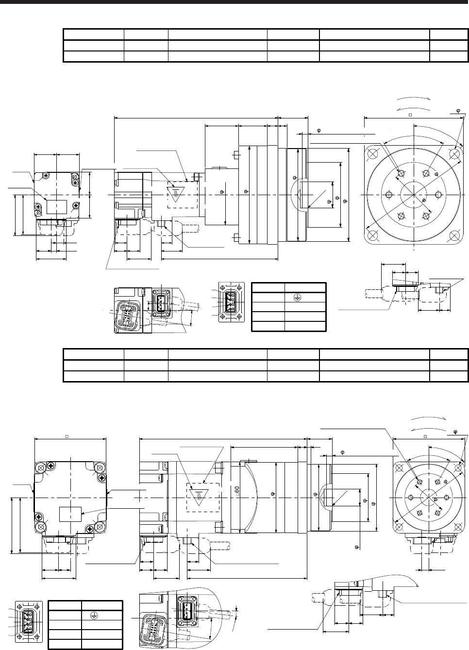
6. HG-MR SERIES/HG-KR SERIES
6 - 36
Model Output [W] Reducer model Reduction ratio Moment of inertia J [× 10-4 kg•m2] Mass [kg]
HG-KR13G5 100 HPG-20A-33-F0JMLAS-S 1/33 0.140 2.6
HG-KR13G5 100 HPG-20A-45-F0JMLAS-S 1/45 0.139 2.6
[Unit: mm]
27.4
4.9
20.720.5
Caution
plate
21
13.7
20.7
Power supply
connector
Motor
plate
Encoder connector
Power supply
connector
19.2
11.711.7
9.9
21.7
Opposite-load side
9.9
11.7 11.7 19.2
10.9
21.7
Caution plate
Motor plate
(Opposite side)
C0.5
2630.5
148.9
106.3
10 8
90 4- 9
37.1
36
6.4
Encoder connector
1
2
3
4
For reverse rotation command
For forward rotation command
Rotation direction
9°
7°
BC38198*
85h7
59
24H7
89
55
84
105
45
45°
Power supply connector
Pin No.
4
3
1
2
Application
W
V
U
(PE)
60°
27+0.4
-0.5
Caution plate
Bottom
Top
Bottom
Top
Bottom
6-M6 Screw hole depth 10
5( 24H7effective range)
Top
Model Output [W] Reducer model Reduction ratio Moment of inertia J [× 10-4 kg•m2] Mass [kg]
HG-KR23G5 200 HPG-14A-05-F0AZW-S 1/5 0.422 1.8
HG-KR23G5 200 HPG-14A-11-F0AZX-S 1/11 0.424 1.9
[Unit: mm]
Bottom
Top
Opposite-load side
140.6
11.711.8
10.9
19.2
9.5
47.1
28.4
13.7 10
9.5
11.8 11.7
19.2
21.7
Top
Caution plate
Top
Motor plate
(Opposite side)
Power supply connector
Encoder connector
Motor
plate
56
C0.5
Power supply connector
8 3
100.4
60 4- 5.5
5.9
60
21.7
46
Encoder connector
1
2
3
4
For reverse rotation command
For forward rotation command
Rotation direction
56h7
40
14H7
55.5
59
6-M4 Screw hole depth 7
70
30
45°
BC38199*
9°
7°
Power supply connector
Pin No.
4
3
1
2
Application
W
V
U
(PE)
60°
21+0.4
-0.5
Caution plate
Caution plate Bottom
Bottom
5( 14H7effective range)
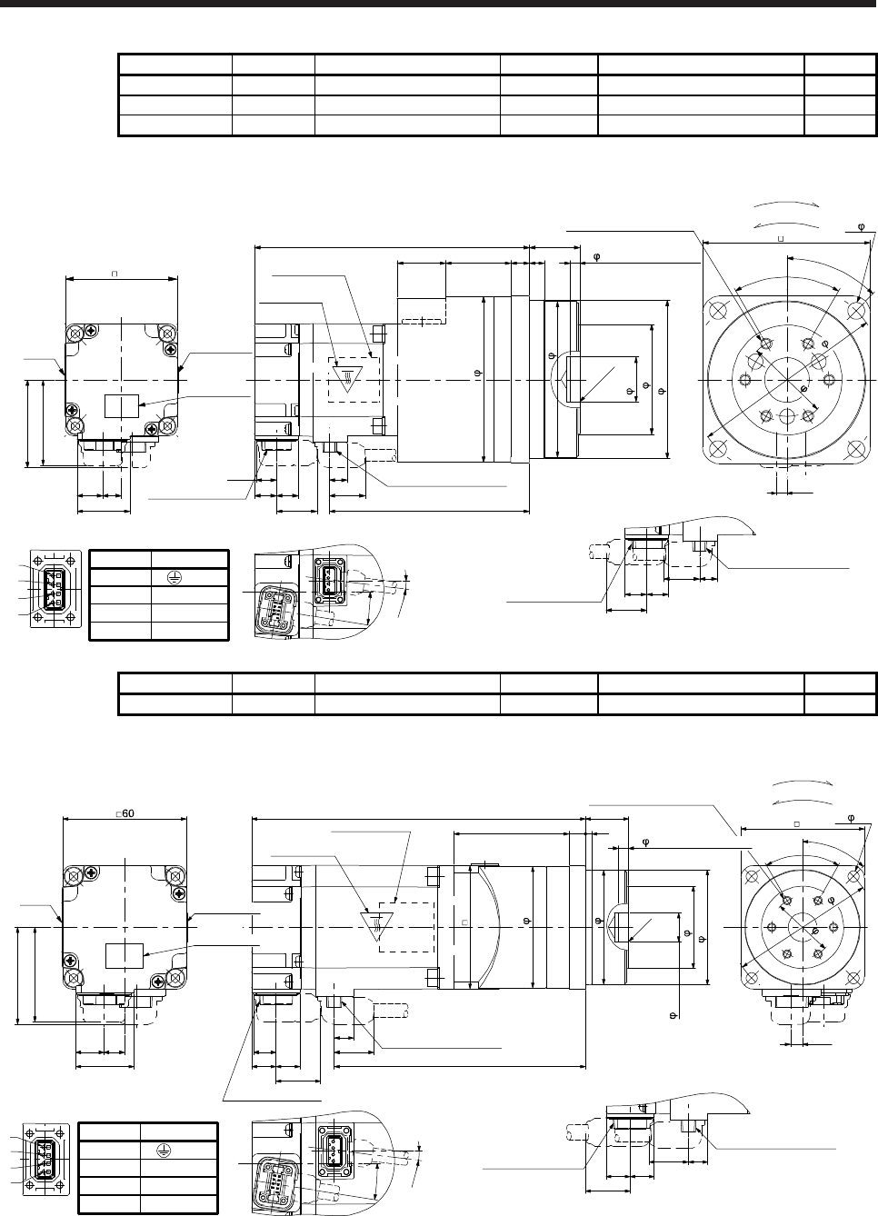
6. HG-MR SERIES/HG-KR SERIES
6 - 37
Model Output [W] Reducer model Reduction ratio Moment of inertia J [× 10-4 kg•m2] Mass [kg]
HG-KR23G5 200 HPG-20A-21-F0EKS-S 1/21 0.719 3.4
HG-KR23G5 200 HPG-20A-33-F0ELS-S 1/33 0.673 3.4
HG-KR23G5 200 HPG-20A-45-F0ELS-S 1/45 0.672 3.4
[Unit: mm]
Caution plate
Bottom
Top
Opposite-load side
107.4
11.711.8
10.9
19.2
9.5
28.4
13.7 10
9.5
11.811.7
19.2
21.7
Caution plate
Top
Caution plate
Motor plate
(Opposite side)
Power supply connector
Encoder connector
Motor
plate
Power supply connector
60
810
35
147.6
26
C0.5
90
21.7
47.1
46
Encoder connector
1
2
3
4
5.9
For reverse rotation command
For forward rotation command
Rotation direction
9°
7°
5( 24H7effective range)
6-M6 Screw hole depth 10
85h7
59
24H7
84
89
45°
105
45
4- 9
BC40901*
Power supply connector
Pin No.
4
3
1
2
Application
W
V
U
(PE)
60°
27+0.4
-0.5
Bottom
Top
Bottom
Model Output [W] Reducer model Reduction ratio Moment of inertia J [× 10-4 kg•m2] Mass [kg]
HG-KR43G5 400 HPG-14A-05-J2CBJS-S 1/5 0.572 2.3
[Unit: mm]
Bottom
Top
46
28.4
13.7 10
162.3
11.711.8
10.9 19.2
9.5 Power supply connector
Encoder connector
21.7
Bottom
Top
Motor plate
(Opposite side)
Caution plate
Motor
plate
60
5.9
38
122.1
60
56
47.1
Opposite-load side
9.5
11.8 11.7
19.2
21.7
Power supply connector
Encoder connector
C0.5
1
2
3
4
For reverse rotation command
For forward rotation command
Rotation direction
59
55.5
14H7
40
56h7
6-M4 Screw hole depth 7
45°
70
30
4- 5.5
9°
7°
BC38186*
Power supply connector
Pin No.
4
3
1
2
Application
W
V
U
(PE)
60°
21+0.4
-0.5
Caution plate
Caution plate Top
Bottom
5( 14H7effective range)
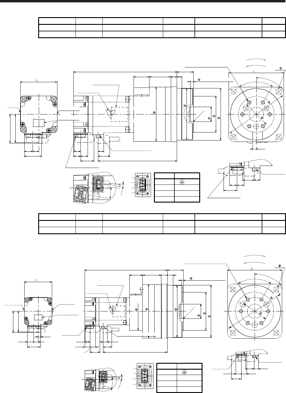
6. HG-MR SERIES/HG-KR SERIES
6 - 38
Model Output [W] Reducer model Reduction ratio Moment of inertia J [× 10-4 kg•m2] Mass [kg]
HG-KR43G5 400 HPG-20A-11-F0EKS-S 1/11 0.947 3.9
HG-KR43G5 400 HPG-20A-21-F0EKS-S 1/21 0.869 3.9
[Unit: mm]
Bottom
Top
Opposite-load side
46
28.4
13.7 10
9.5
11.811.7
19.2
21.7
Power supply
connector
Encoder connector
169.3
11.711.8
10.9
19.2
9.5 Power supply connector
Encoder connector
21.7
Bottom
Top
Motor plate
(Opposite side)
Caution plate
Motor
plate
26 35
C0.5
90
47.1
129.1
810
60
1
2
3
4
5.9
For reverse rotation command
For forward rotation command
Rotation direction
7°
9°
89
84
24H7
59
85h7
6-M6 Screw hole depth 10 4- 9
45°
45
BC38187*
Power supply connector
Pin No.
4
3
1
2
Application
W
V
U
(PE)
60°
27+0.4
-0.5
105
Caution plate
Caution plate
Top
Bottom
5( 24H7effective range)
Model Output [W] Reducer model Reduction ratio Moment of inertia J [× 10-4 kg•m2] Mass [kg]
HG-KR43G5 400 HPG-32A-33-F0RLAS-S 1/33 0.921 6.0
HG-KR43G5 400 HPG-32A-45-F0RLAS-S 1/45 0.915 6.0
[Unit: mm]
Caution plate
Bottom
Top
Opposite-load side
46
28.4
13.7 10
9.5
11.8 11.7
19.2
21.7
Caution plate
Power supply
connector
Encoder
connector
181.3
11.7
11.8
10.9
19.2
9.5
Encoder
connector
21.7
Bottom
Top
Motor plate
(Opposite side)
Caution plate
Motor plate
47.1
141.1
4129 13 13
120
C0.5
60
1
2
3
4
For reverse rotation command
For forward rotation command
Rotation direction
5.9
BC38188*
9°
7°
115h7
84
32H7
114
118
84
4- 11
5( 32H7effective range)
6-M8 Screw hole depth 12
45°
135
60
Power supply connector
Pin No.
4
3
1
2
Application
W
V
U
(PE)
60°
35+0.4
-0.5
Power supply connector
Top
Bottom
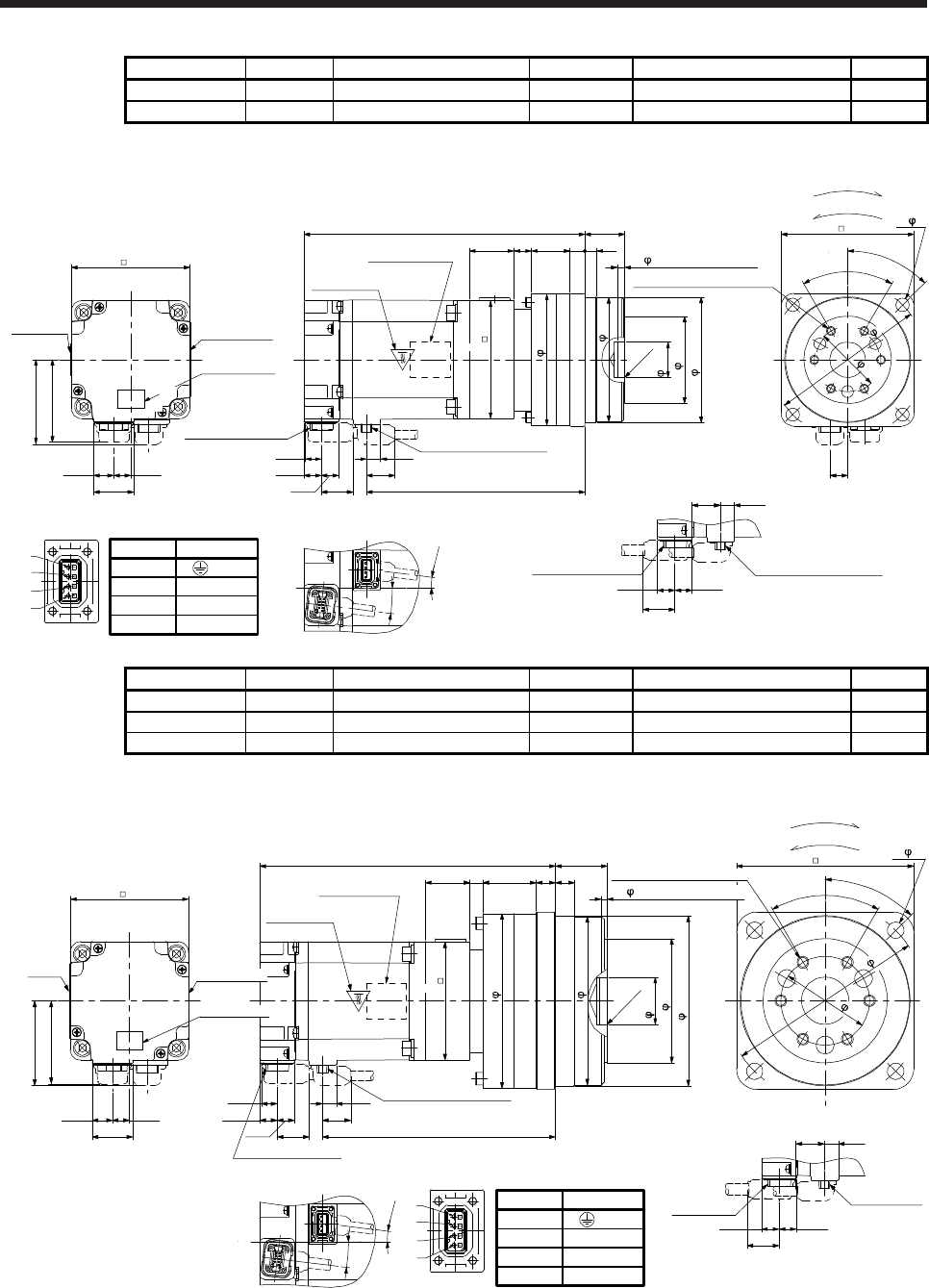
6. HG-MR SERIES/HG-KR SERIES
6 - 39
Model Output [W] Reducer model Reduction ratio Moment of inertia J [× 10-4 kg•m2] Mass [kg]
HG-KR73G5 750 HPG-20A-05-F0FEOS-S 1/5 1.91 4.8
HG-KR73G5 750 HPG-20A-11-F0FEPS-S 1/11 1.82 5.1
[Unit: mm]
Bottom
Top Top
9.510.7
11.8
11.7
19.2
147.627.4
13.7 11.5
56
Power supply connector
Encoder connector
Motor plate
(Opposite side)
Caution plate
Caution plate
Caution plate
21.7
Motor plate
57.1
1026
12
30
C0.5
190 90
12
Opposite-load side
11.8 11.7
21.7
9.5
19.2
8
80
Power supply connectorEncoder connector
1
2
3
4
For reverse rotation command
For forward rotation command
Rotation direction
80
89
84
24H7
59
85h7
5( 24H7effective range)
6-M6 Screw hole depth 10
45°
105
45
4- 9
7°
7°
BC38189*
Power supply connector
Pin No.
4
3
1
2
Application
W
V
U
(PE)
60°
27 +0.4
-0.5
Bottom
Bottom
Top
Model Output [W] Reducer model Reduction ratio Moment of inertia J [× 10-4 kg•m2] Mass [kg]
HG-KR73G5 750 HPG-32A-21-F0SEIS-S 1/21 2.01 7.2
HG-KR73G5 750 HPG-32A-33-F0SEJS-S 1/33 1.79 7.2
HG-KR73G5 750 HPG-32A-45-F0SEJS-S 1/45 1.79 7.2
[Unit: mm]
Bottom
Top Top
9.510.7
11.8
11.7
19.2
157.627.4
13.7 11.5
56
Bottom
Top
Power supply connector
Encoder connector
Motor plate
(Opposite side)
Caution plate
21.7
Motor
plate
57.1
200
1313
36930
C0.5
120
Opposite-load side
11.8 11.7
21.7
9.5
19.2
80
Power supply
connector
Encoder
connector
1
2
3
4
For reverse rotation command
For forward rotation command
Rotation direction
7°
7°
118
114
32H7
84
115h7
4- 11
45°
135
60
BC38190*
Power supply connector
Pin No.
4
3
1
2
Application
W
V
U
(PE)
60°
35+0.4
-0.5
80
Caution plate
Caution plate
Bottom
6-M8 Screw hole depth 12
5( 32H7effective range)
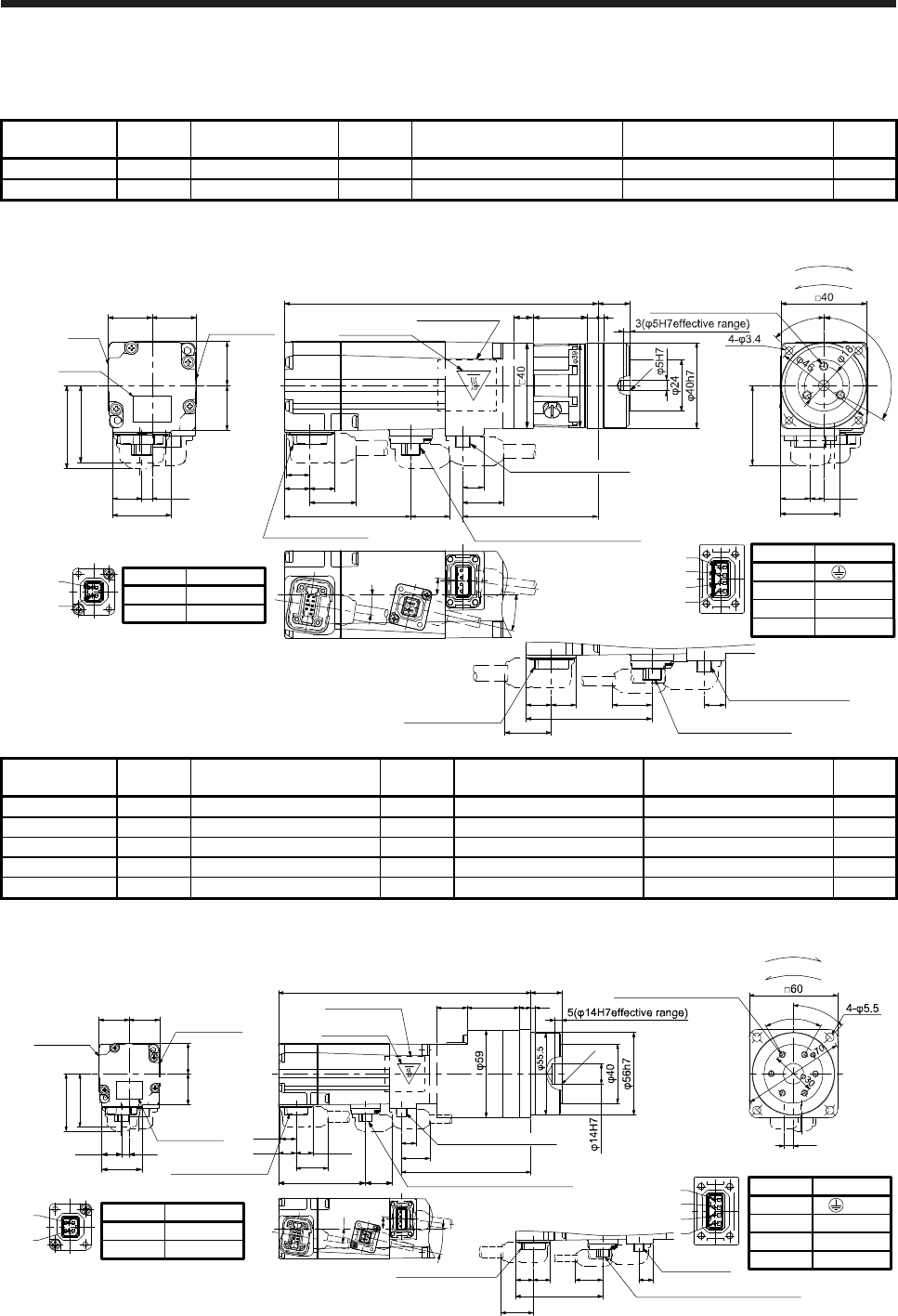
6. HG-MR SERIES/HG-KR SERIES
6 - 40
6.8.6 With flange-output type reducer for high precision applications, flange mounting (with an
electromagnetic brake)
Model Output
[W] Reducer model Reduction
ratio Brake static friction torque [N•m] Moment of inertia J [× 10-4 kg•m2] Mass
[kg]
HG-KR053BG5 50 HPG-11B-05-F0ADG-S 1/5 0.32 0.0507 0.75
HG-KR053BG5 50 HPG-11B-09-F0ADG-S 1/9 0.32 0.0497 0.76
[Unit: mm]
27.4
4.9 9.9
11.7
Bottom
11.7
20.720.5
Caution
plate
21
13.7
20.7
36
7°
19.2
10.9
21.7
63.3
146.5
Encoder connector
Caution plate
Motor plate
(Opposite side)
Motor
plate Caution plate
Top
18.458.8
Electromagnetic brake connector
13°
38.8
9°
45°
6.4
27.5
13.9
For reverse rotation command
For forward rotation command
Rotation direction
37.1
Power supply connector
1
2
3
4
Electromagnetic brake connector
2
1
21
Encoder connector
Power supply connector
BC41764*
11.711.7 9.9
21.7 Opposite-load side
58.8
18.4
Electromagnetic brake
connector
2.5
5
C0.5
25.5
9
15+0.25
-0.20
120°
3-M4 Screw hole depth 6
Power supply connector
Pin No.
1
2
Application
B2
B1
Pin No.
4
3
1
2
Application
W
V
U
(PE)
Bottom
Top
Bottom
Top
Model Output
[W] Reducer model Reduction
ratio
Brake static friction torque
[N•m]
Moment of inertia J
[× 10-4 kg•m2]
Mass
[kg]
HG-KR053BG5 50 HPG-14A-05-F0CBJS-S 1/5 0.32 0.115 1.3
HG-KR053BG5 50 HPG-14A-11-F0CBKS-S 1/11 0.32 0.107 1.4
HG-KR053BG5 50 HPG-14A-21-F0CBKS-S 1/21 0.32 0.0980 1.4
HG-KR053BG5 50 HPG-14A-33-F0CBLS-S 1/33 0.32 0.0920 1.4
HG-KR053BG5 50 HPG-14A-45-F0CBLS-S 1/45 0.32 0.0920 1.4
[Unit: mm]
2
1Pin No.
1
2
Application
B2
B1
Electromagnetic brake connector 1
2
3
4
Pin No.
4
3
1
2
Application
W
V
U
(PE)
Power supply connector
21
+0.4
9.9
21.7 19.2
10.9
87.8
Caution plate
Motor plate
(Opposite side)
Top
171
321
Encoder connector Electromagnetic brake connector
18.458.8
7°
13°
9°
35 8
C0.5
Encoder connector
Power supply
connector
11.711.7 9.9
21.7 Opposite-load side
58.8
18.4
Electromagnetic brake connector
6-M4 Screw hole depth 7
45°
6.4
60°
For reverse rotation command
For forward rotation command
Rotation direction
BC41097*
11.7 11.7
-0.5
Power supply connector
Top
Bottom
Bottom
27.4
4.9
20.720.5
Caution plate
21
13.7
20.7
36
Motor plate
Caution plate
38.8
Bottom
Top
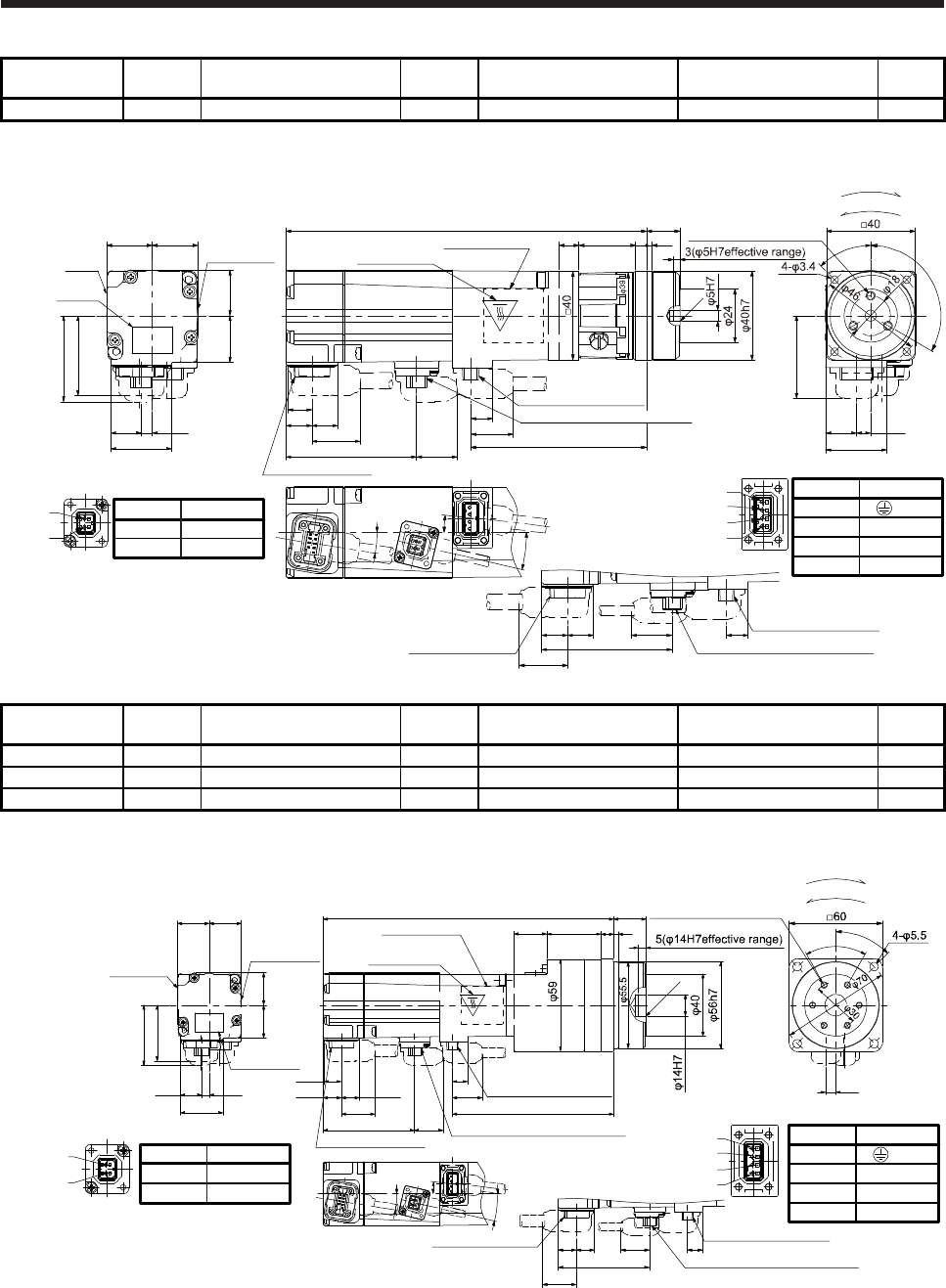
6. HG-MR SERIES/HG-KR SERIES
6 - 41
Model Output
[W] Reducer model Reduction
ratio
Brake static friction torque
[N•m]
Moment of inertia J
[× 10-4 kg•m2]
Mass
[kg]
HG-KR13BG5 100 HPG-11B-05-F0ADG-S 1/5 0.32 0.0872 0.95
[Unit: mm]
27.4
4.9
9.9
11.7
Bottom
11.7
20.720.5
Caution
plate
21
13.7
20.7
36
7°
19.2
10.9
21.7 79.3
162.5
Encoder connector
Power supply connector
Caution plate
Motor plate
(Opposite side)
Motor
plate Caution plate
Bottom
Top
18.4
58.8
13°
38.8
9°
45°
6.4
27.5
13.9
For reverse rotation command
For forward rotation command
Rotation direction
37.1
Power supply connector
1
2
3
4
Electromagnetic brake connector
2
1
Encoder connector
Power supply connector
BC41766*
11.711.7 9.9
21.7 Opposite-load side
58.8
18.4
Electromagnetic brake connector
15+0.25
-0.20
2.5
25.5 5
C0.5
9
120°
3-M4 Screw hole depth 6
Pin No.
4
3
1
2
Application
W
V
U
(PE)
Pin No.
1
2
Application
B2
B1
Top
Bottom
Electromagnetic brake connector
Top
Model Output
[W] Reducer model Reduction
ratio
Brake static friction torque
[N•m]
Moment of inertia J
[× 10-4 kg•m2]
Mass
[kg]
HG-KR13BG5 100 HPG-14A-05-F0CBJS-S 1/5 0.32 0.152 1.5
HG-KR13BG5 100 HPG-14A-11-F0CBKS-S 1/11 0.32 0.144 1.6
HG-KR13BG5 100 HPG-14A-21-F0CBKS-S 1/21 0.32 0.135 1.6
[Unit: mm]
1
2
3
4
Pin No.
4
3
1
2
Application
W
V
U
(PE)
Power supply connector
2
1Pin No.
1
2
Application
B2
B1
Electromagnetic brake connector
27.4
4.9
9.9
11.7 11.7
21
13.7
20.7
36
7°
19.2
10.9
21.7 103.8
187
Encoder connector
Power supply connector
Caution plate
Motor plate
(Opposite side)
Motor plate
Caution plate
18.458.8 Electromagnetic brake connector
13°
38.8
9°
20.720.5 38
3521
C0.5
6-M4 Screw hole depth 7
45°
6.4
60°
For reverse rotation command
For forward rotation command
Rotation direction
Encoder connector Power supply connector
11.711.7 9.9
21.7 Opposite-load side
58.8
18.4
Electromagnetic brake connector
2
1
BC41098*
21+0.4
-0.5
Top
Bottom
Bottom
Caution plate
Bottom
Top
Top
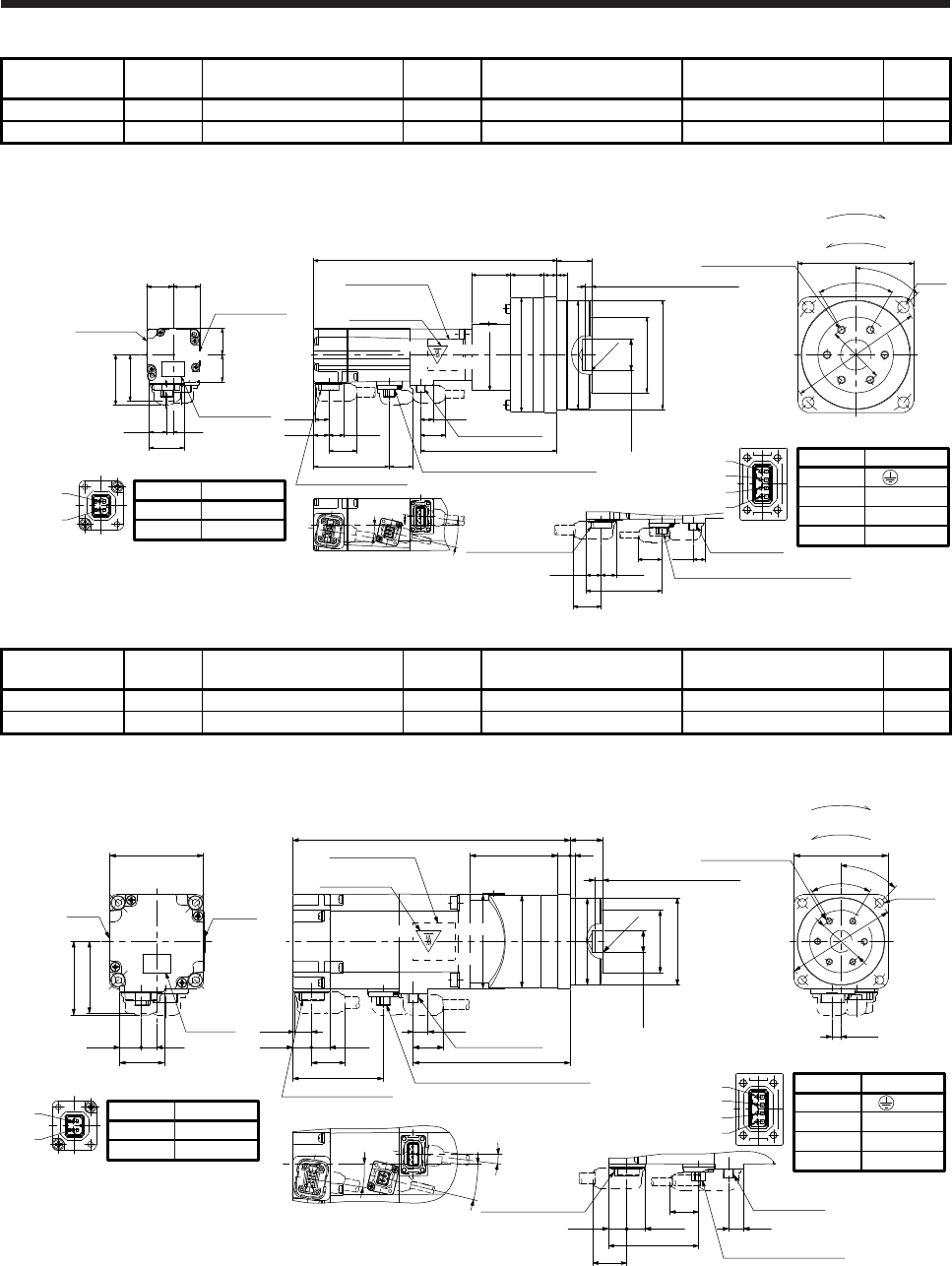
6. HG-MR SERIES/HG-KR SERIES
6 - 42
Model Output
[W] Reducer model Reduction
ratio
Brake static friction torque
[N•m]
Moment of inertia J
[× 10-4 kg•m2]
Mass
[kg]
HG-KR13BG5 100 HPG-20A-33-F0JMLAS-S 1/33 0.32 0.146 2.8
HG-KR13BG5 100 HPG-20A-45-F0JMLAS-S 1/45 0.32 0.145 2.8
[Unit: mm]
4.9
Caution plate
21
27.4
13.7
20.7
36
Motor plate
Caution plate
38.8
20.720.5
Pin No.
1
2
Application
B2
B1
Electromagnetic brake connector
2
1
2630.5
φ89
189.5
Caution plate
9.9
11.7 11.7 19.2
10.9
21.7 106.3
Encoder connector
Power supply
connector
18.458.8 Electromagnetic brake connector
7°
13°
9°
Encoder connector Power supply
connector
11.711.7
9.9
21.7 Opposite-load side
58.8
18.4
Electromagnetic brake connector
φ
85h7
810
φ
59
φ84
C0.5
5(φ24H7 effective range )
φ
24H7
27+0.4
-0.5 6-M6 Screw hole
depth 10
4-φ9
45°
60°
φ45
φ105
Pin No.
4
3
1
2
Application
W
V
U
(PE)
Power supply connector
1
2
3
4
BC41099A
□90
Top
Motor plate
(Opposite side)
Bottom
Top
Bottom
Top
φ55
For reverse rotation command
For forward rotation command
Rotation direction
Bottom
Model Output
[W] Reducer model Reduction
ratio
Brake static friction torque
[N•m]
Moment of inertia J
[× 10-4 kg•m2]
Mass
[kg]
HG-KR23BG5 200 HPG-14A-05-F0AZW-S 1/5 1.3 0.444 2.2
HG-KR23BG5 200 HPG-14A-11-F0AZX-S 1/11 1.3 0.446 2.3
[Unit: mm]
Caution
plate
47.1
28.4
13.7 10
Caution
plate
Motor
plate
□60
46
Pin No.
1
2
Application
B2
B1
Electromagnetic brake connector
2
1
177.4
Caution plate
φ59
100.4
11.711.8
10.9
19.2
9.5 Power supply
connector
Encoder connector
21.7
57.8 Electromagnetic brake connector
φ56h7
56 38
φ55.5
φ40
φ14H7
C0.5
5(φ14H7effective range)
21+0.4
-0.5
4-φ5.5
45°
5.9
φ30
φ70
6-M4 Screw hole
depth 7
60°
□60
Pin No.
4
3
1
2
Application
W
V
U
(PE)
Power supply connector
1
2
3
4
9°
7°
13.5°
Opposite-load side
9.511.8 11.7
57.8
Power supply
connector
Encoder connector
21.7
18.3
Electromagnetic brake
connector
BC41100*
Bottom
Top
Motor plate
(Opposite side)
For reverse rotation command
For forward rotation command
Rotation direction
Bottom
Top Top
Bottom
60
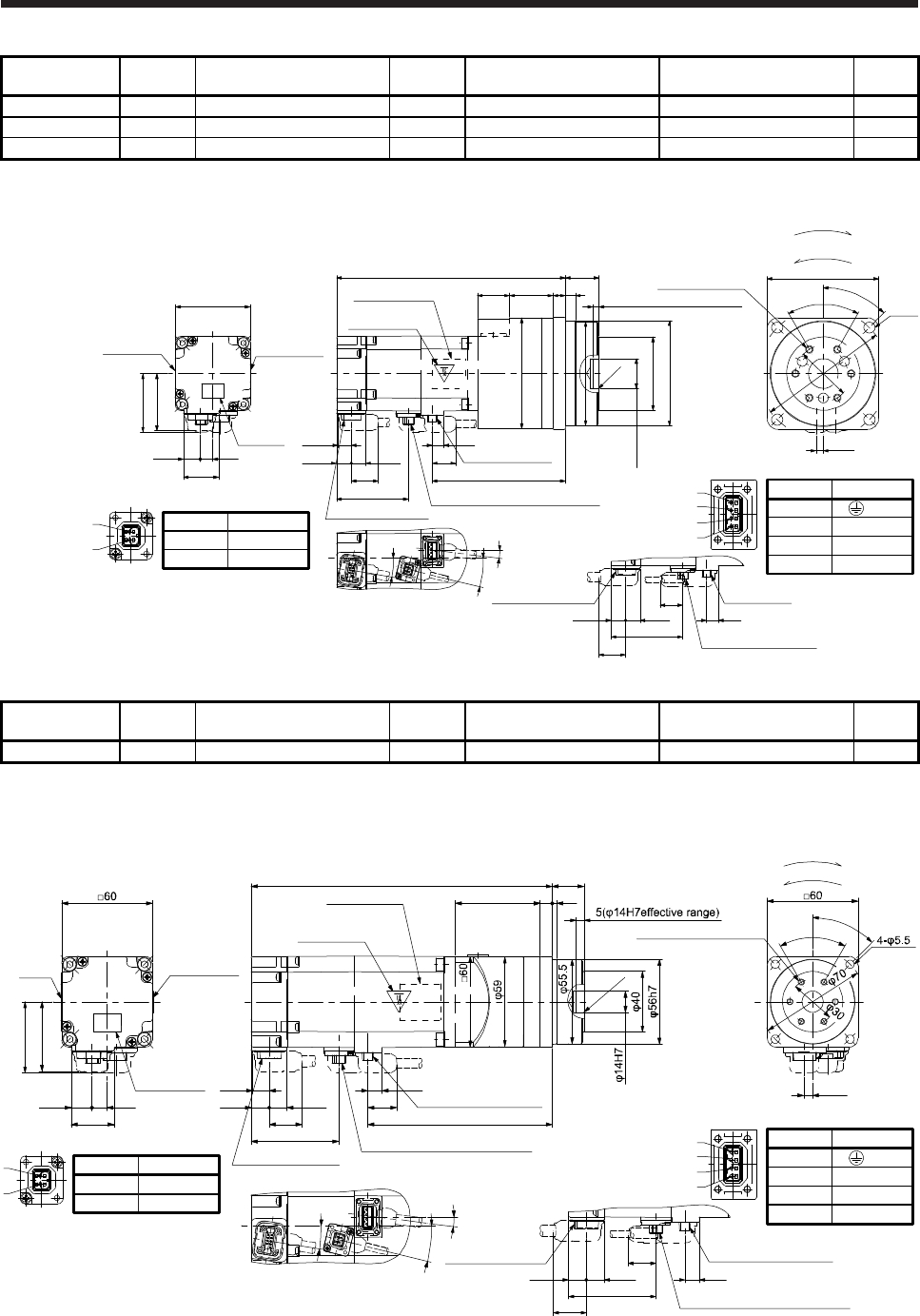
6. HG-MR SERIES/HG-KR SERIES
6 - 43
Model Output
[W] Reducer model Reduction
ratio
Brake static friction torque
[N•m]
Moment of inertia J
[× 10-4 kg•m2]
Mass
[kg]
HG-KR23BG5 200 HPG-20A-21-F0EKS-S 1/21 1.3 0.741 3.8
HG-KR23BG5 200 HPG-20A-33-F0ELS-S 1/33 1.3 0.695 3.8
HG-KR23BG5 200 HPG-20A-45-F0ELS-S 1/45 1.3 0.694 3.8
[Unit: mm]
Caution
plate
47.1
28.4
13.7 10
Caution plate
Motor plate
□60
46
Pin No.
1
2
Application
B2
B1
Electromagnetic brake connector
2
1
103526
184.4 27+0.4
-0.5
8
φ89
107.4
11.711.8
10.9
19.2
9.5 Power supply
connector
Encoder connector
21.7
Caution plate
57.8 Electromagnetic brake connector
φ24H7
φ59
φ85h7
φ84
5(φ24H7 effective range )
C0.5
6-M6 Screw hole
depth 10
45°
4-φ9
φ45
φ105
60°
5.9
□90
Pin No.
4
3
1
2
Application
W
V
U
(PE)
Power supply connector
1
2
3
4
Opposite-load side
9.5
11.7
57.8
Power supply
connector
18.3
Electromagnetic brake
connector
11.8
Encoder connector
21.7
BC41101*
9°
7°
13.5°
Motor plate
(Opposite side)
For reverse rotation command
For forward rotation command
Rotation direction
Bottom
Top
Bottom
Top
Bottom
Top
Model Output
[W] Reducer model Reduction
ratio
Brake static friction torque
[N•m]
Moment of inertia J
[× 10-4 kg•m2]
Mass
[kg]
HG-KR43BG5 400 HPG-14A-05-F0AZW-S 1/5 1.3 0.594 2.7
[Unit: mm]
2
1Pin No.
1
2
Application
B2
B1
Electromagnetic brake connector 1
2
3
4
Pin No.
4
3
1
2
Application
W
V
U
(PE)
Power supply connector
Opposite-load side
9.511.8 11.7
57.8
Power supply connector
Encoder connector
21.7
18.3
Electromagnetic brake connector
BC41102*
199.1
Top
Motor plate
(Opposite side)
Caution plate
9°
7°
Caution plate
122.1
11.711.8
10.9
19.2
9.5
Power supply connector
Encoder connector
47.1
28.4
13.7 10
Caution plate
21.7
Motor
plate
57.8
13.5°
Electromagnetic brake connector
856 3
45°
5.9
6-M4 Screw hole depth 7
C0.5
60°
46
For reverse rotation command
For forward rotation command
Rotation direction
21
+0.4
-0.5
Bottom
Top
Bottom
Top
Bottom
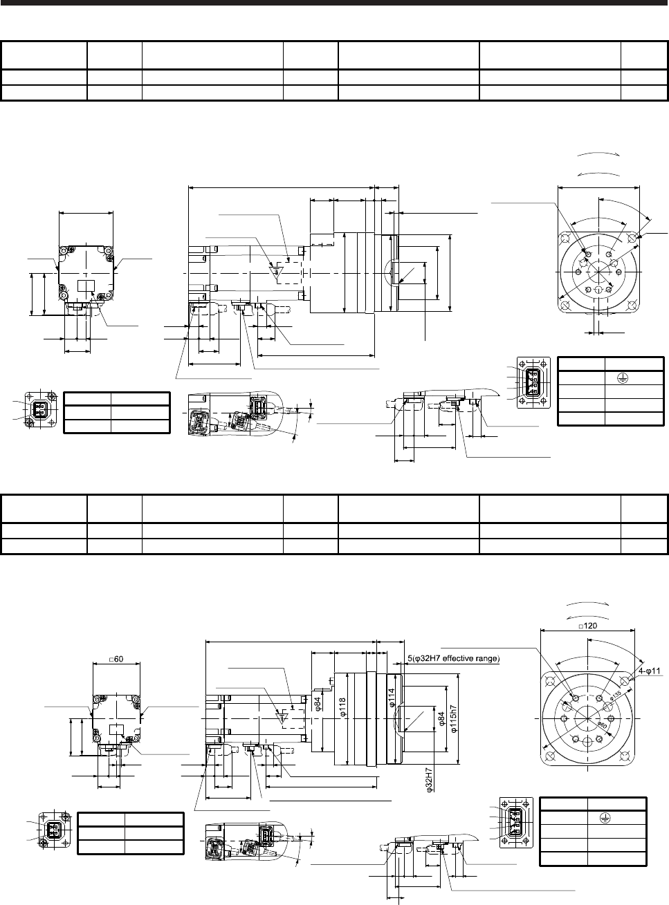
6. HG-MR SERIES/HG-KR SERIES
6 - 44
Model Output
[W] Reducer model Reduction
ratio
Brake static friction torque
[N•m]
Moment of inertia J
[× 10-4 kg•m2]
Mass
[kg]
HG-KR43BG5 400 HPG-20A-11-F0EKS-S 1/11 1.3 0.969 4.3
HG-KR43BG5 400 HPG-20A-21-F0EKS-S 1/21 1.3 0.891 4.3
[Unit: mm]
Caution
plate
47.1
28.4
13.7 10
Caution
plate
Motor
plate
□60
46
11.711.8
10.9
Encoder connector
21.7
57.8
206.1
Caution plate
129.1
19.2
9.5
Power supply
connector
Electromagnetic brake connector
3526
φ89
810
φ59
φ84
φ85h7
φ24H7
5(φ24H7 effective
range )
C0.5
27+0.4
-0.5
φ105
45°
4-φ9
6-M6 Screw hole
depth 10
5.9
φ45
60°
□90
Pin No.
4
3
1
2
Application
W
V
U
(PE)
Power supply connector
BC41103*
1
2
3
4
Opposite-load side
9.5
11.8 11.7
57.8
Power supply
connector
Encoder connector
21.7
18.3
Electromagnetic brake
connector
9°
7°
13.5°
Pin No.
1
2
Application
B2
B1
Electromagnetic brake connector
2
1
Bottom
Top
Motor plate
(Opposite side)
Top Top
Bottom Bottom
For reverse rotation command
For forward rotation command
Rotation direction
Model Output
[W] Reducer model Reduction
ratio
Brake static friction torque
[N•m]
Moment of inertia J
[× 10-4 kg•m2]
Mass
[kg]
HG-KR43BG5 400 HPG-32A-33-F0RLAS-S 1/33 1.3 0.943 6.4
HG-KR43BG5 400 HPG-32A-45-F0RLAS-S 1/45 1.3 0.937 6.4
[Unit: mm]
218.1
Top
Motor plate
(Opposite side)
Caution plate
131341
29
9°
7°
Caution plate
141.1
11.711.8
10.9
19.2
9.5
Encoder connector
47.1
28.4
13.7 10
Caution plate
21.7
Motor plate
57.8
13.5°
Electromagnetic brake connector
5.9
45°
C0.5
6-M8 Screw hole depth12
60°
46
2
1Pin No.
1
2
Application
B2
B1
Electromagnetic brake connector 1
2
3
4
Pin No.
4
3
1
2
Application
W
V
U
(PE)
Power supply connector
Opposite-load side
9.511.8 11.7
57.8
Power supply
connector
Encoder connector
21.7
18.3
Electromagnetic brake connector
BC41104*
For reverse rotation command
For forward rotation command
Rotation direction
35+0.4
-0.5
Power supply connector
Bottom Bottom
Top
Bottom
Top
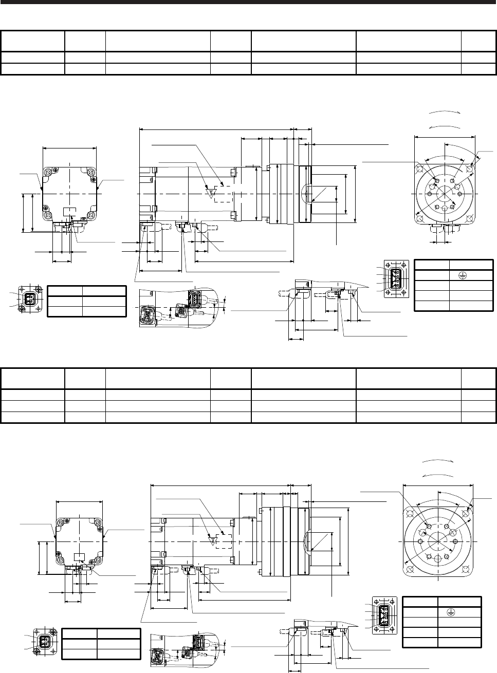
6. HG-MR SERIES/HG-KR SERIES
6 - 45
Model Output
[W] Reducer model Reduction
ratio
Brake static friction torque
[N•m]
Moment of inertia J
[× 10-4 kg•m2]
Mass
[kg]
HG-KR73BG5 750 HPG-20A-05-F0FEOS-S 1/5 2.4 2.02 5.8
HG-KR73BG5 750 HPG-20A-11-F0FEPS-S 1/11 2.4 1.93 6.1
[Unit: mm]
27.4
13.7 11.5
56
Caution plate
Caution
plate
Motor
plate
57.1
□80
Pin No.
1
2
Application
B2
B1
Electromagnetic brake connector
2
1
230.3
Caution plate
810261230 5(φ24H7 effective range)
27+0.4
-0.5
φ59
φ89
φ85h7
φ84
□80
C0.5
10.7
11.8 11.7
147.6
Power supply connector
Encoder connector
21.7
63.1 Electromagnetic brake connector
9.5
19.2
φ24H7
7°
7°
7°
Opposite-load side
Encoder connector
11.8 11.7
63.1
9.5
Power supply
connector
21.7
18.4
Electromagnetic brake
connector
6-M6 Screw hole
depth 10
φ105
φ45
45°
12
4-φ9
60°
□90
1
2
3
4
Pin No.
4
3
1
2
Application
Power supply connector
W
V
U
(PE)
BC41105*
Top
Bottom
Motor plate
(Opposite side)
For reverse rotation command
For forward rotation command
Rotation direction
Top
Bottom Bottom
Top
Model Output
[W] Reducer model Reduction
ratio
Brake static friction torque
[N•m]
Moment of inertia J
[× 10-4 kg•m2]
Mass
[kg]
HG-KR73BG5 750 HPG-32A-21-F0SEIS-S 1/21 2.4 2.12 8.2
HG-KR73BG5 750 HPG-32A-33-F0SEJS-S 1/33 2.4 1.90 8.2
HG-KR73BG5 750 HPG-32A-45-F0SEJS-S 1/45 2.4 1.90 8.2
[Unit: mm]
27.4
13.7 11.5
56
Caution plate
Caution plate
Motor plate
57.1
□80
12
Pin No.
1
2
Application
B2
B1
Electromagnetic brake connector
2
1
1313
369
φ118
240.3
Caution plate
30
□80
Power supply connector
Encoder connector
Electromagnetic brake connector
5(φ32H7 effective range)
35+0.4
-0.5
9.5
10.7
11.8 11.7 19.2
157.621.7
63.1
φ84
φ115h7
φ114
φ32H7
C0.5
7°
7°
7°
Opposite-load side
Encoder connector
11.8 11.7
63.1 9.5
Power supply
connector
21.7
18.4
Electromagnetic brake connector
1
2
3
4
6-M8 Screw
hole depth 12
φ135
φ60
4-φ11
45°
60°
□120
Pin No.
4
3
1
2
Application
W
V
U
(PE)
Power supply connector
BC41106*
Motor plate
(Opposite side)
Bottom
Top
Top
For reverse rotation command
For forward rotation command
Rotation direction
Bottom
Top
Bottom
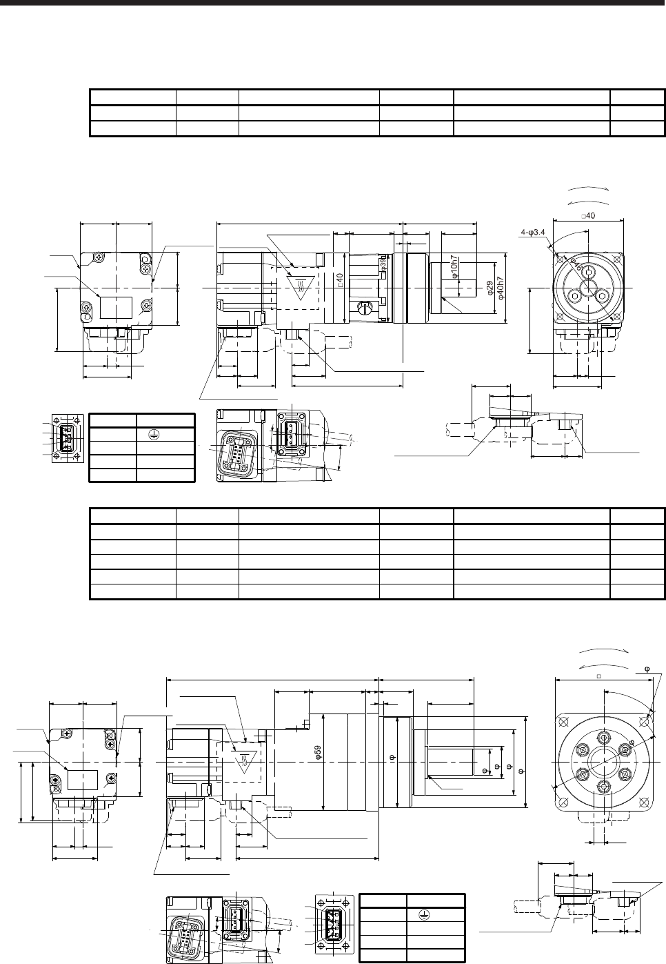
6. HG-MR SERIES/HG-KR SERIES
6 - 46
6.8.7 With shaft-output type reducer for high precision applications, flange mounting (without an
electromagnetic brake)
Model Output [W] Reducer model Reduction ratio Moment of inertia J [× 10-4 kg•m2] Mass [kg]
HG-KR053G7 50 HPG-11B-05-F20ADG-S 1/5 0.0512 0.58
HG-KR053G7 50 HPG-11B-09-F20ADG-S 1/9 0.0492 0.58
[Unit: mm]
45°
6.4
27.5
42
15
27.4
4.9 9.9
11.7 11.7 13.9
20.720.5
Caution
plate
21
13.7
20.7
36
7°
19.2
10.9
21.7
9°
63.3
105.9
5
Encoder connector
Caution plate
Motor plate
(Opposite side)
Motor
plate
Caution plate
Top
25.5 20
2.5
R0.4
For reverse rotation command
For forward rotation command
Rotation direction
Encoder connector
Power supply
connector
BC40938*
19.2
11.711.7
9.9
21.7
Opposite-load side
Power supply connector
1
2
3
4
37.1
9
Pin No.
4
3
1
2
Application
W
V
U
(PE)
Top
Bottom
Bottom
Top
Bottom
Power supply connector
Model Output [W] Reducer model Reduction ratio Moment of inertia J [× 10-4 kg•m2] Mass [kg]
HG-KR053G7 50 HPG-14A-05-J2CBJS-S 1/5 0.119 1.2
HG-KR053G7 50 HPG-14A-11-J2CBKS-S 1/11 0.106 1.3
HG-KR053G7 50 HPG-14A-21-J2CBKS-S 1/21 0.0960 1.3
HG-KR053G7 50 HPG-14A-33-J2CBLS-S 1/33 0.0900 1.3
HG-KR053G7 50 HPG-14A-45-J2CBLS-S 1/45 0.0900 1.3
[Unit: mm]
27.4
4.9
20.720.5
Caution
plate
21
13.7
20.7
36
Encoder connector
Power supply
connector
19.2
11.711.7
9.9
21.7
Opposite-load side
Motor
plate
130.4
21
58
3
835
28
21
R0.4
60
6.4
9.9
11.7 11.7 19.2
10.9
21.7 87.8
Encoder connector
Power supply connector
Caution plate
Motor plate
(Opposite side)
Top
37.1
1
2
3
4
For reverse rotation command
For forward rotation command
Rotation direction
BC38191*
55.5
16h7
20
40
56h7
9°
7°
45°
4- 5.5
70
Power supply connector
Pin No.
4
3
1
2
Application
W
V
U
(PE)
Caution plate
Bottom
Top
Bottom
Top
Bottom
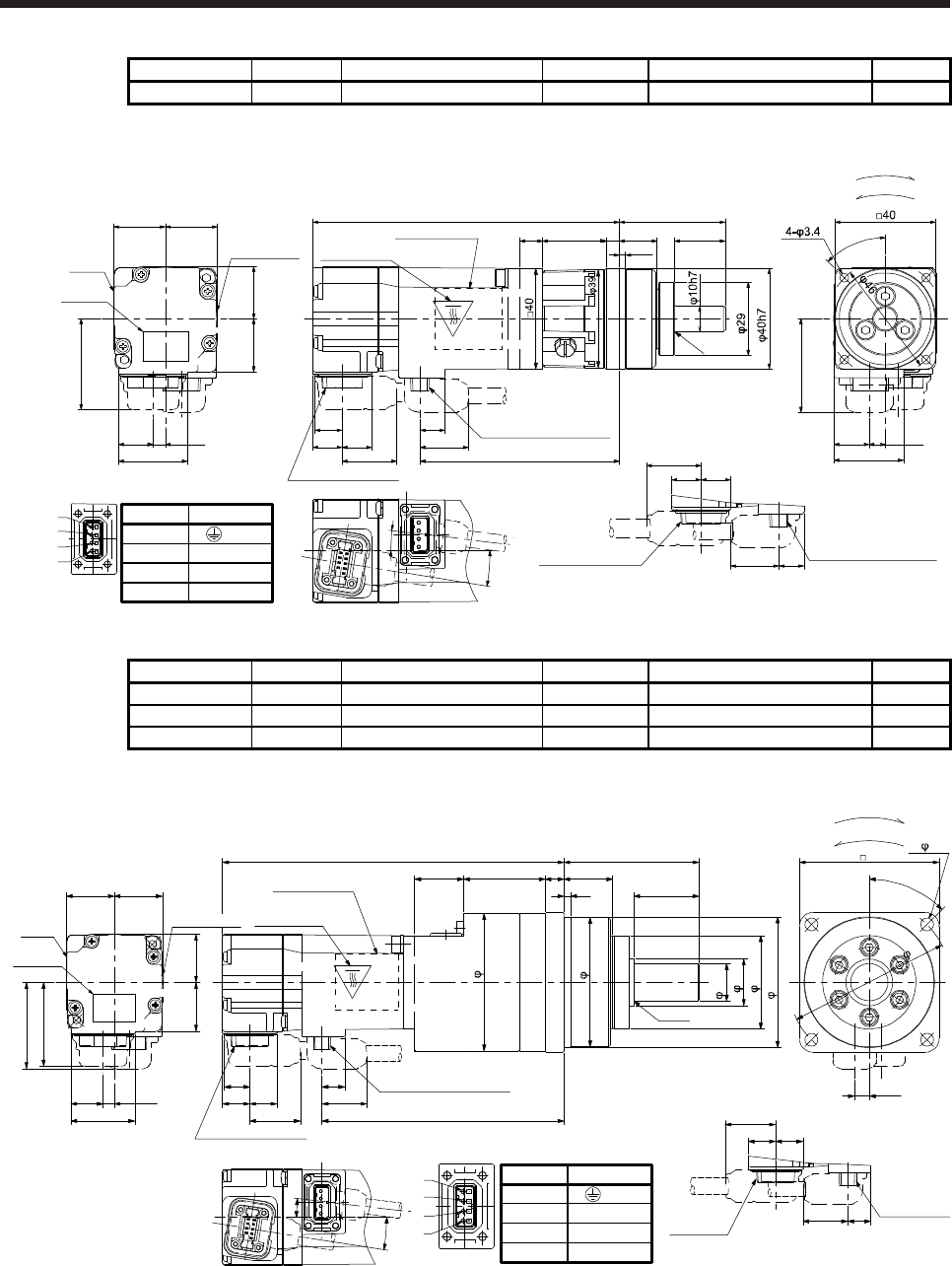
6. HG-MR SERIES/HG-KR SERIES
6 - 47
Model Output [W] Reducer model Reduction ratio Moment of inertia J [× 10-4 kg•m2] Mass [kg]
HG-KR13G7 100 HPG-11B-05-J20ADG-S 1/5 0.0839 0.78
[Unit: mm]
27.4
4.9
20.720.5
Caution
plate
21
13.7
20.7
36
Motor
plate
9.9
11.7 11.7
25.5
19.2
10.9
21.7 79.3
121.9
5
Power supply connector
Caution plate
Motor plate
(Opposite side)
Bottom
Top
45°
37.1
6.4
27.5
13.9
9°
7°
9
42
15 20
2.5
R0.4
For reverse rotation command
For forward rotation command
Rotation direction
Encoder connector Power supply connector
BC40940*
19.2
11.711.7
9.9
21.7
Opposite-load side
Power supply connector
1
2
3
4
Caution plate
Encoder connector
Pin No.
4
3
1
2
Application
W
V
U
(PE)
Bottom
Top
Top
Bottom
Model Output [W] Reducer model Reduction ratio Moment of inertia J [× 10-4 kg•m2] Mass [kg]
HG-KR13G7 100 HPG-14A-05-J2CBJS-S 1/5 0.152 1.4
HG-KR13G7 100 HPG-14A-11-J2CBKS-S 1/11 0.139 1.5
HG-KR13G7 100 HPG-14A-21-J2CBKS-S 1/21 0.129 1.5
[Unit: mm]
27.4
4.9
20.720.5
Caution
plate
21
13.7
20.7
36
Encoder
connector
Power supply
connector
19.2
11.711.7
9.9
21.7
Opposite-load side
Motor
plate
9.9
11.7 11.7 19.2
10.9
21.7 103.8
146.4
Encoder connector
Power supply connector
Caution plate
Motor plate
(Opposite side)
21
58
3
835
28
21
R0.4
60
6.4
37.1
1
2
3
4
For reverse rotation command
For forward rotation command
Rotation direction
9°
7°
BC38192*
59
55.5
16h7
20
40
56h7
45°
4- 5.5
70
Power supply connector
Pin No.
4
3
1
2
Application
W
V
U
(PE)
Caution plate
Bottom
Top
Bottom
Bottom
Top
Top
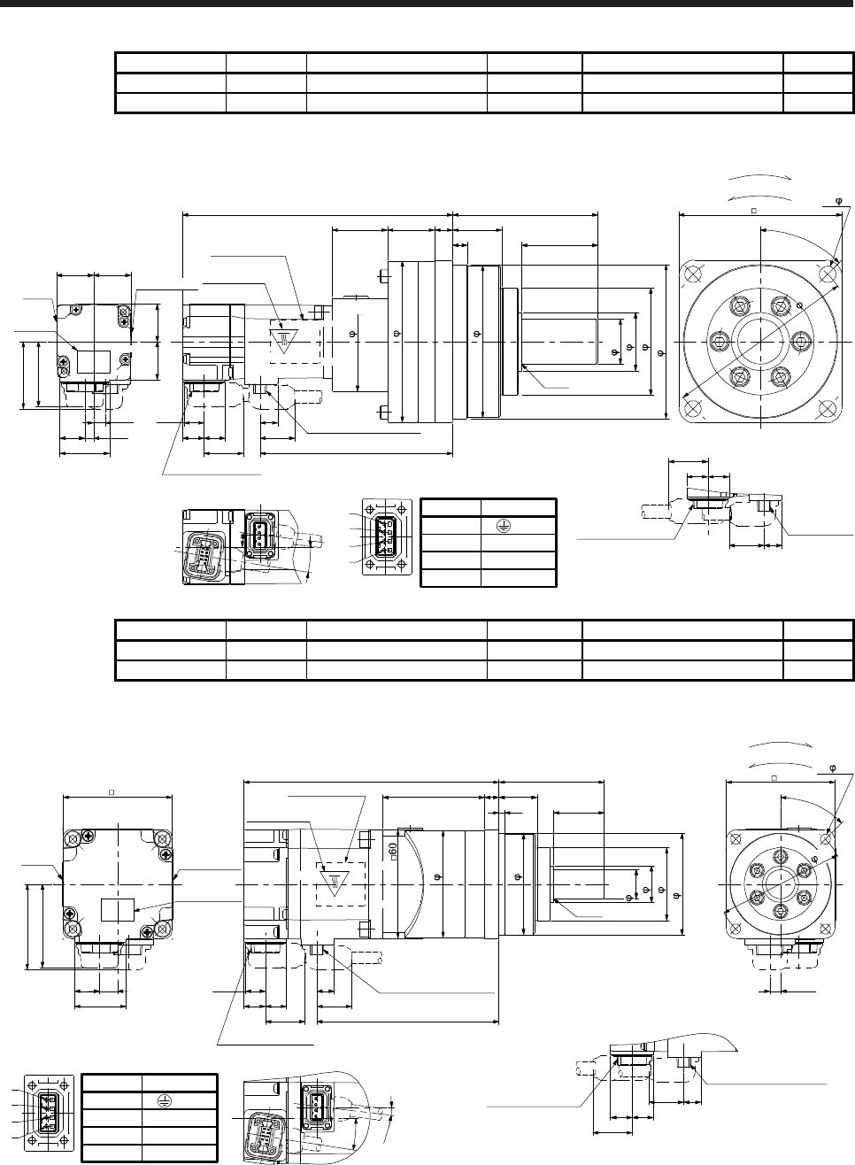
6. HG-MR SERIES/HG-KR SERIES
6 - 48
Model Output [W] Reducer model Reduction ratio Moment of inertia J [× 10-4 kg•m2] Mass [kg]
HG-KR13G7 100 HPG-20A-33-J2JMLAS-S 1/33 0.141 3.0
HG-KR13G7 100 HPG-20A-45-J2JMLAS-S 1/45 0.139 3.0
[Unit: mm]
27.4
4.9
20.720.5
Caution
plate
21
13.7
20.7
36
Encoder connector
Power supply
connector
19.2
11.711.7
9.9
21.7
Opposite-load side
Motor
plate
9.9
11.711.7 19.2
10.9
21.7 106.3
Encoder connector
Power supply connector
Caution plate
Motor plate
(Opposite side)
8
27
80
26 10
42
30.5
R0.4
90148.9
37.1
6.4
1
2
3
4
For reverse rotation command
For forward rotation command
Rotation direction
9°
7°
BC38193*
55
89
84
25h7
32
59
85h7
45°
4- 9
Power supply connector
Pin No.
4
3
1
2
Application
W
V
U
(PE)
105
Bottom
Top
Bottom
Bottom
Top
Caution plate
Top
Model Output [W] Reducer model Reduction ratio Moment of inertia J [× 10-4 kg•m2] Mass [kg]
HG-KR23G7 200 HPG-14A-05-J2AZW-S 1/5 0.428 1.9
HG-KR23G7 200 HPG-14A-11-J2AZX-S 1/11 0.424 2.0
[Unit: mm]
Caution plate
Bottom
Top
140.6
100.4
11.711.8
10.9
19.2
9.5 Power supply connector
Encoder connector
5.9
46
28.4
13.7 10
Caution plate
21.7
Top
Caution plate
Motor plate
(Opposite side)
Motor
plate
9.5
11.811.7
19.2
21.7
Power supply connector
Encoder connector
6058
28
56 21
3
8
R0.4
47.1
60
For reverse rotation command
For forward rotation command
Rotation direction
59
55.5
20
40
56h7
9°
7°
BC38194*
1
2
3
4
4- 5.5
45°
70
Power supply connector
Pin No.
4
3
1
2
Application
W
V
U
(PE)
16h7
Bottom
Top
Bottom
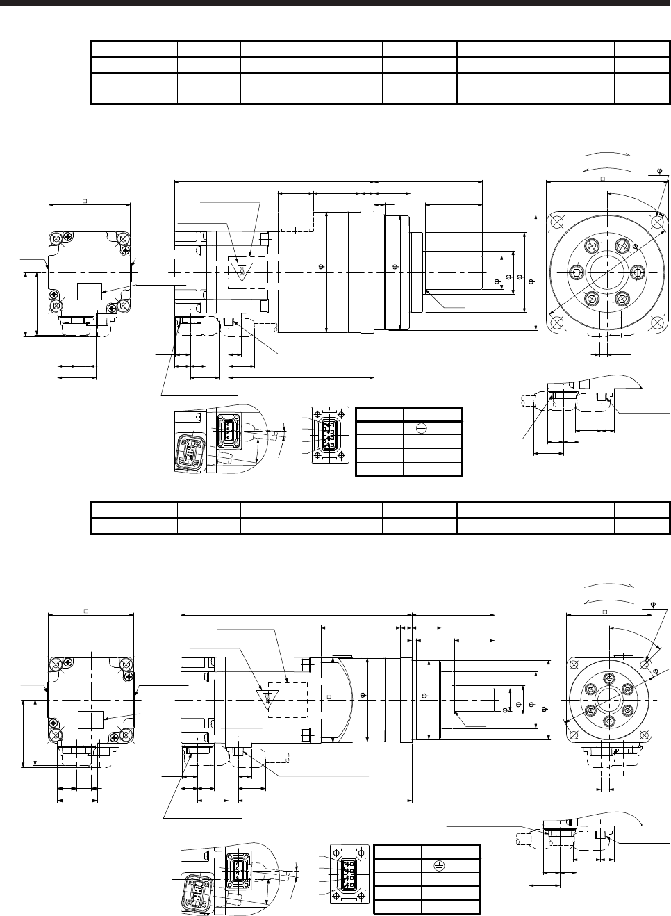
6. HG-MR SERIES/HG-KR SERIES
6 - 49
Model Output [W] Reducer model Reduction ratio Moment of inertia J [× 10-4 kg•m2] Mass [kg]
HG-KR23G7 200 HPG-20A-21-J2EKS-S 1/21 0.721 3.8
HG-KR23G7 200 HPG-20A-33-J2ELS-S 1/33 0.674 3.8
HG-KR23G7 200 HPG-20A-45-J2ELS-S 1/45 0.672 3.8
[Unit: mm]
Bottom
Top
147.6
107.4
11.711.8
10.9
19.2
9.5 Power supply connector
Encoder connector
5.9
46
28.4
13.7 10
21.7
Caution plate
Motor plate
(Opposite side)
Motor
plate
Opposite-load side
9.5
11.811.7
19.2
21.7
Power supply
connector
Encoder
connector
47.1
60
90
10
35 27
80
8 42
26
R0.4
1
2
3
4
For reverse rotation command
For forward rotation command
Rotation direction
9°
7°
BC38195*
89
84
25h7
32
59
85h7
45°
105
4- 9
Power supply connector
Pin No.
4
3
1
2
Application
W
V
U
(PE)
Caution plate
Caution plate
Bottom
Top
Bottom
Top
Model Output [W] Reducer model Reduction ratio Moment of inertia J [× 10-4 kg•m2] Mass [kg]
HG-KR43G7 400 HPG-14A-05-J2AZW-S 1/5 0.578 2.4
[Unit: mm]
1
2
3
4
Bottom
Top
Opposite-load side
46
28.4
13.7 10
9.5
11.811.7
19.2
21.7
Power supply
connector
Encoder connector
162.3
122.1
11.711.8
10.9
19.2
9.5 Power supply connector
Encoder connector
Bottom
Top
Motor plate
(Opposite side)
Caution plate
Motor
plate
8
56
58 60
For reverse rotation command
For forward rotation command
Rotation direction
21
3 28
R0.4
5.9
47.1
60
21.7
45°
70
4- 5.5
60
59
55.5
20
40
56h7
BC40909*
9°
7°
Power supply connector
Pin No.
4
3
1
2
Application
W
V
U
(PE)
16h7
Top
Bottom
Caution plate
Caution plate
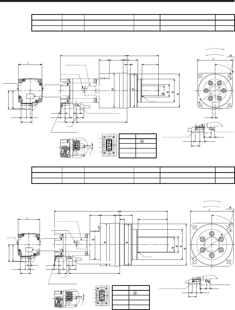
6. HG-MR SERIES/HG-KR SERIES
6 - 50
Model Output [W] Reducer model Reduction ratio Moment of inertia J [× 10-4 kg•m2] Mass [kg]
HG-KR43G7 400 HPG-20A-11-J2EKS-S 1/11 0.955 4.3
HG-KR43G7 400 HPG-20A-21-J2EKS-S 1/21 0.871 4.3
[Unit: mm]
Bottom
Opposite-load side
46
28.4
13.7 10
9.5
11.8 11.7
19.2
21.7
Power supply
connector
Encoder connector
169.3
129.111.7
11.8
10.9
19.2
9.5
Power supply connector
Encoder connector
Bottom
Top
Motor plate
(Opposite side)
Caution plate
Motor plate
R0.4
5.9
90
47.1
60
80
428
27
10
3526
21.7
1
2
3
4
For reverse rotation command
For forward rotation command
Rotation direction
BC40910*
45
4- 9
105
89
84
25h7
32
59
85h7
9
7
Power supply connector
Pin No.
4
3
1
2
Application
W
V
U
(PE)
Caution plate
Caution plate
Top
Top
Bottom
Model Output [W] Reducer model Reduction ratio Moment of inertia J [× 10-4 kg•m2] Mass [kg]
HG-KR43G7 400 HPG-32A-33-J2RLAS-S 1/33 0.927 7.4
HG-KR43G7 400 HPG-32A-45-J2RLAS-S 1/45 0.918 7.4
[Unit: mm]
Opposite-load side
46
28.4
13.7 10
9.5
11.8 11.7
19.2
21.7
Power supply
connector
Encoder connector
181.3
141.111.7
11.8
10.9
19.2
9.5
Encoder connector
Top
Motor plate
(Opposite side)
Motor
plate
R0.4
47.1
60
133
82
13
35
13
4129
120
21.7
5.9
1
2
3
4
For reverse rotation command
For forward rotation command
Rotation direction
9°
7°
84
118
114
40h7
44
84
115h7
BC40911*
45°
4- 11
135
Power supply connector
Pin No.
4
3
1
2
Application
W
V
U
(PE)
Power supply connector
Top
Bottom Caution plate
Caution plate
Caution plate
Top
Bottom
Bottom
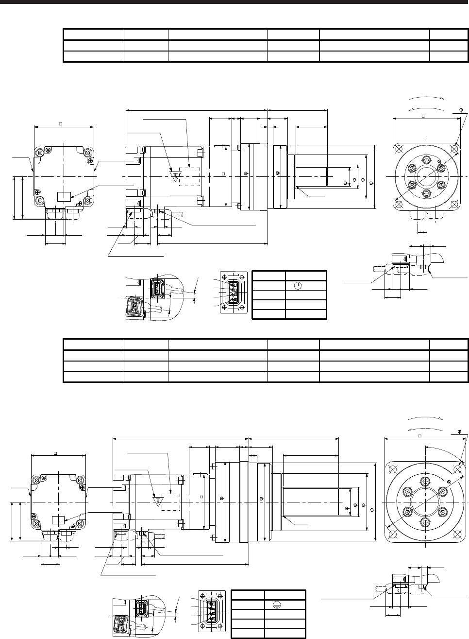
6. HG-MR SERIES/HG-KR SERIES
6 - 51
Model Output [W] Reducer model Reduction ratio Moment of inertia J [× 10-4 kg•m2] Mass [kg]
HG-KR73G7 750 HPG-20A-05-J2FEOS-S 1/5 1.95 5.2
HG-KR73G7 750 HPG-20A-11-J2FEPS-S 1/11 1.83 5.5
[Unit: mm]
R0.4
80
428
271026
12
Opposite-load side
Bottom
Top
190
9.510.7
11.8
11.7
19.2
147.627.4
13.7 11.5
56
Bottom
Power supply connector
Encoder connector
Motor plate
(Opposite side)
Caution plate
Encoder
connector 11.8 11.7
21.7
21.7 9.5
19.2
Power supply
connector
Motor
plate
30
12
90
80
57.1
1
2
3
4
For reverse rotation command
For forward rotation command
Rotation direction
7°
7°
BC40912*
80
84
89
25h7
32
59
85h7
4- 9
105
Power supply connector
Pin No.
4
3
1
2
Application
W
V
U
(PE)
Caution plate
Caution plate
Top
Top
Bottom
Model Output [W] Reducer model Reduction ratio Moment of inertia J [× 10-4 kg•m2] Mass [kg]
HG-KR73G7 750 HPG-32A-21-J2SEIS-S 1/21 2.03 8.6
HG-KR73G7 750 HPG-32A-33-J2SEJS-S 1/33 1.80 8.6
HG-KR73G7 750 HPG-32A-45-J2SEJS-S 1/45 1.79 8.6
[Unit: mm]
R0.4
133
82
13
35
13
369
Opposite-load side
Bottom
Top
200
9.510.7
11.8
11.7
19.2
157.6
27.4
13.7 11.5
56
Bottom
Power supply connector
Encoder connector
Motor plate
(Opposite side)
Caution plate
Encoder connector
11.8 11.7
21.7
21.7 9.5
19.2
Power supply
connector
Motor
plate
30
80
120
57.1
12
1
2
3
4
For reverse rotation command
For forward rotation command
Rotation direction
7°
7°
BC40913*
80
118
114
44
84
115h7
40h7
45°
4- 11
135
Power supply connector
Pin No.
4
3
1
2
Application
W
V
U
(PE)
Caution plate
Caution plate
Top
Top
Bottom
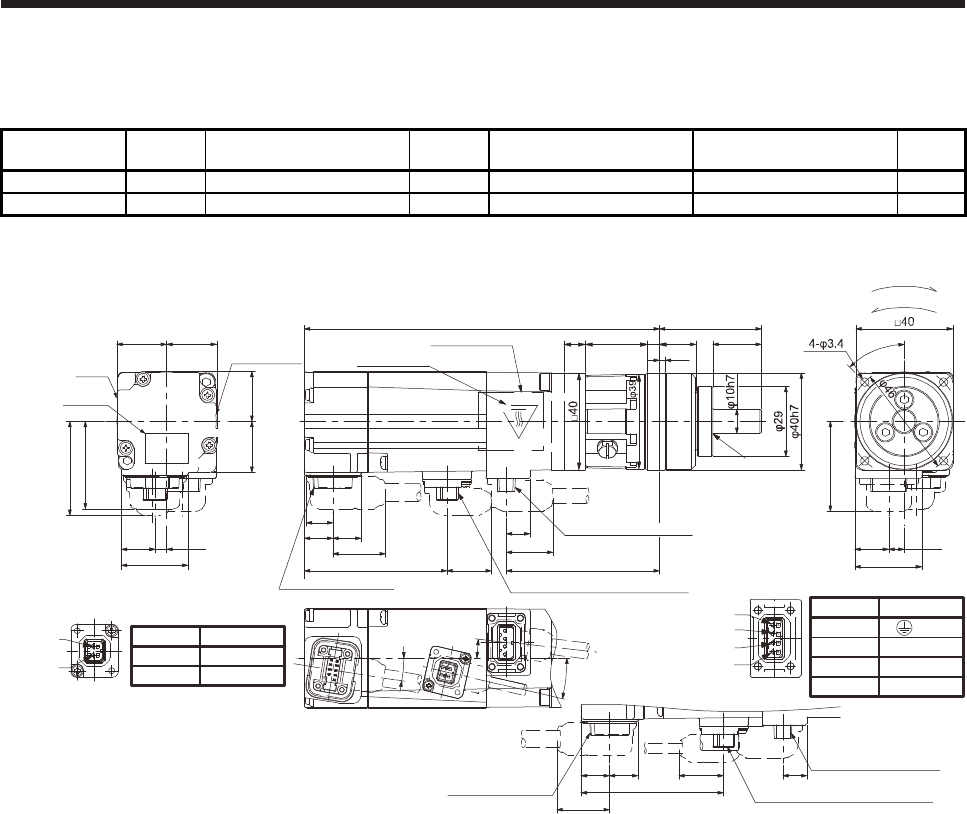
6. HG-MR SERIES/HG-KR SERIES
6 - 52
6.8.8 With shaft-output type reducer for high precision applications, flange mounting (with an
electromagnetic brake)
Model Output
[W] Reducer model Reduction
ratio
Brake static friction torque
[N•m]
Moment of inertia J
[× 10-4 kg•m2]
Mass
[kg]
HG-KR053BG7 50 HPG-11B-05-J20ADG-S 1/5 0.32 0.0534 0.78
HG-KR053BG7 50 HPG-11B-09-J20ADG-S 1/9 0.32 0.0514 0.78
[Unit: mm]
27.4
4.9
9.9
11.7 11.7
20.720.5
Caution
plate
21
13.7
20.7
36
7°
19.2
10.9
21.7
63.3
146.5
Encoder connector
Caution plate
Motor plate
(Opposite side)
Motor
plate
Caution plate
Top
18.458.8
Electromagnetic brake connector
13°
38.8
9°
45°
6.4
27.5
42
15
13.9
525.5 20
2.5
R0.4
For reverse rotation command
For forward rotation command
Rotation direction
37.1
Power supply connector
1
2
3
4
Electromagnetic brake connector
2
1
2
1
Encoder connector
Power supply connector
11.711.7 9.9
21.7 Opposite-load side
58.8
18.4
Electromagnetic brake connector
BC41765*
9
Power supply connector
Bottom
Pin No.
4
3
1
2
Application
W
V
U
(PE)
Pin No.
1
2
Application
B2
B1
Top
Bottom
Bottom
Top
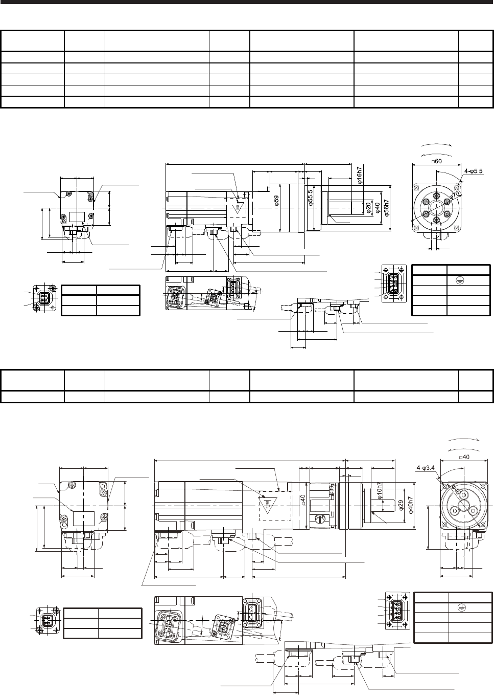
6. HG-MR SERIES/HG-KR SERIES
6 - 53
Model Output
[W] Reducer model Reduction
ratio
Brake static friction torque
[N•m]
Moment of inertia J
[× 10-4 kg•m2]
Mass
[kg]
HG-KR053BG7 50 HPG-14A-05-J2CBJS-S 1/5 0.32 0.121 1.4
HG-KR053BG7 50 HPG-14A-11-J2CBKS-S 1/11 0.32 0.108 1.5
HG-KR053BG7 50 HPG-14A-21-J2CBKS-S 1/21 0.32 0.0980 1.5
HG-KR053BG7 50 HPG-14A-33-J2CBLS-S 1/33 0.32 0.0920 1.5
HG-KR053BG7 50 HPG-14A-45-J2CBLS-S 1/45 0.32 0.0920 1.5
[Unit: mm]
1
2
3
4
Pin No.
4
3
1
2
Application
W
V
U
(PE)
Power supply connector
2
1Pin No.
1
2
Application
B2
B1
Electromagnetic brake connector
9.9
21.7
19.2
10.9
11.7 11.7
87.8
Caution plate
Motor plate
(Opposite side)
Top
171
3
21 21
58
Encoder connector Electromagnetic brake connector18.458.8
7°
13°
9°
35 8
45°
6.4
R0.4
28
27.4
4.9
20.720.5
Caution plate
21
13.7
20.7
36
Motor plate
Caution plate
38.8
BC41107*
For reverse rotation command
For forward rotation command
Rotation direction
Encoder connector Power supply connector
11.711.7
9.9
21.7 Opposite-load side
58.8
18.4
Electromagnetic brake connector
Power supply connector
Bottom
Top
Top
Bottom
Bottom
Model Output
[W] Reducer model Reduction
ratio
Brake static friction torque
[N•m]
Moment of inertia J
[× 10-4 kg•m2]
Mass
[kg]
HG-KR13BG7 50 HPG-11B-05-J20ADG-S 1/5 0.32 0.0899 0.98
[Unit: mm]
27.4
4.9 9.9
11.7 11.7
20.720.5
Caution
plate
21
13.7
20.7
36
7°
19.2
10.9
21.7
79.3
162.5
Encoder connector
Power supply connector
Caution plate
Motor plate
(Opposite side)
Motor
plate Caution plate
Bottom
Top
18.458.8
13°
38.8
9°
45°
6.4
27.5
42
15
13.9
525.5 20
2.5
R0.4
For reverse rotation comma
n
For forward rotation comma
n
Rotation direction
37.1
Power supply connector
1
2
3
4
Electromagnetic brake connector
2
1
Encoder connector
Power supply connector
BC41767*
11.711.7 9.9
21.7 Opposite-load side
58.8
18.4
Electromagnetic brake connector
9
Pin No.
1
2
Application
B2
B1
Pin No.
4
3
1
2
Application
W
V
U
(PE)
Bottom
Top
Top
Bottom
Electromagnetic brake connector
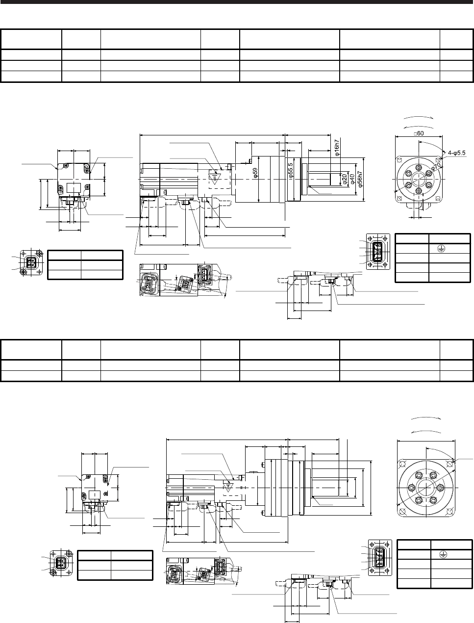
6. HG-MR SERIES/HG-KR SERIES
6 - 54
Model Output
[W] Reducer model Reduction
ratio
Brake static friction torque
[N•m]
Moment of inertia J
[× 10-4 kg•m2]
Mass
[kg]
HG-KR13BG7 100 HPG-14A-05-J2CBJS-S 1/5 0.32 0.158 1.6
HG-KR13BG7 100 HPG-14A-11-J2CBKS-S 1/11 0.32 0.145 1.7
HG-KR13BG7 100 HPG-14A-21-J2CBKS-S 1/21 0.32 0.135 1.7
[Unit: mm]
1
2
3
4
Pin No.
4
3
1
2
Application
W
V
U
(PE)
Power supply connector
2
1Pin No.
1
2
Application
B2
B1
Electromagnetic brake connector
27.4
4.9 9.9
11.7
Top
11.7
Caution plate
21
13.7
20.7
36
7°
19.2
10.9
21.7 103.8
187
Encoder connector
Caution plate
Motor plate
(Opposite side)
Motor plate
Caution plate
18.458.8 Electromagnetic brake connector
13°
38.8
9°
20.7
20.5
21
58
3
835
28
21
R0.4
45°
6.4
BC41108*
For reverse rotation command
For forward rotation command
Rotation direction
2
1
Encoder connector Power supply connector
11.711.7
9.9
21.7 Opposite-load side
58.8
18.4
Electromagnetic brake connector
Power supply connector
Top
Bottom
Bottom
Bottom Top
Model Output
[W] Reducer model Reduction
ratio
Brake static friction torque
[N•m]
Moment of inertia J
[× 10-4 kg•m2]
Mass
[kg]
HG-KR13BG7 100 HPG-20A-33-J2JMLAS-S 1/33 0.32 0.147 3.2
HG-KR13BG7 100 HPG-20A-45-J2JMLAS-S 1/45 0.32 0.145 3.2
[Unit: mm]
BC41109A
Power supply
connector
Opposite-load side
Electromagnetic brake
connector
Encoder connector
Power supply
connector
Caution plate
Motor plate
(Opposite side)
Electromagnetic brake connector
Caution plate
Motor
plate
Caution plate
Pin No.
1
2
Application
B2
B1
Electromagnetic brake connecto
Encoder connector
11.711.7
21.7
58.8
45°
4-φ9
9.918.4
□90
φ105
Pin No.
4
3
1
2
Application
W
V
U
(PE)
Power supply connector
27.4
4.9
21
13.7
20.7
36
38.8
20.720.5
2
1
9.9
11.7 11.7 19.2
10.9
21.7
106.3
18.458.8
7°
13°
9°
8
27
80
26 10
42
φ25h7
30.5
φ55
φ89
φ84
189.5
φ85h7
φ59
φ32
R0.4
1
2
3
4
Bottom Bottom
Top Top
For reverse rotation command
For forward rotation command
Rotation direction
Bottom
Top
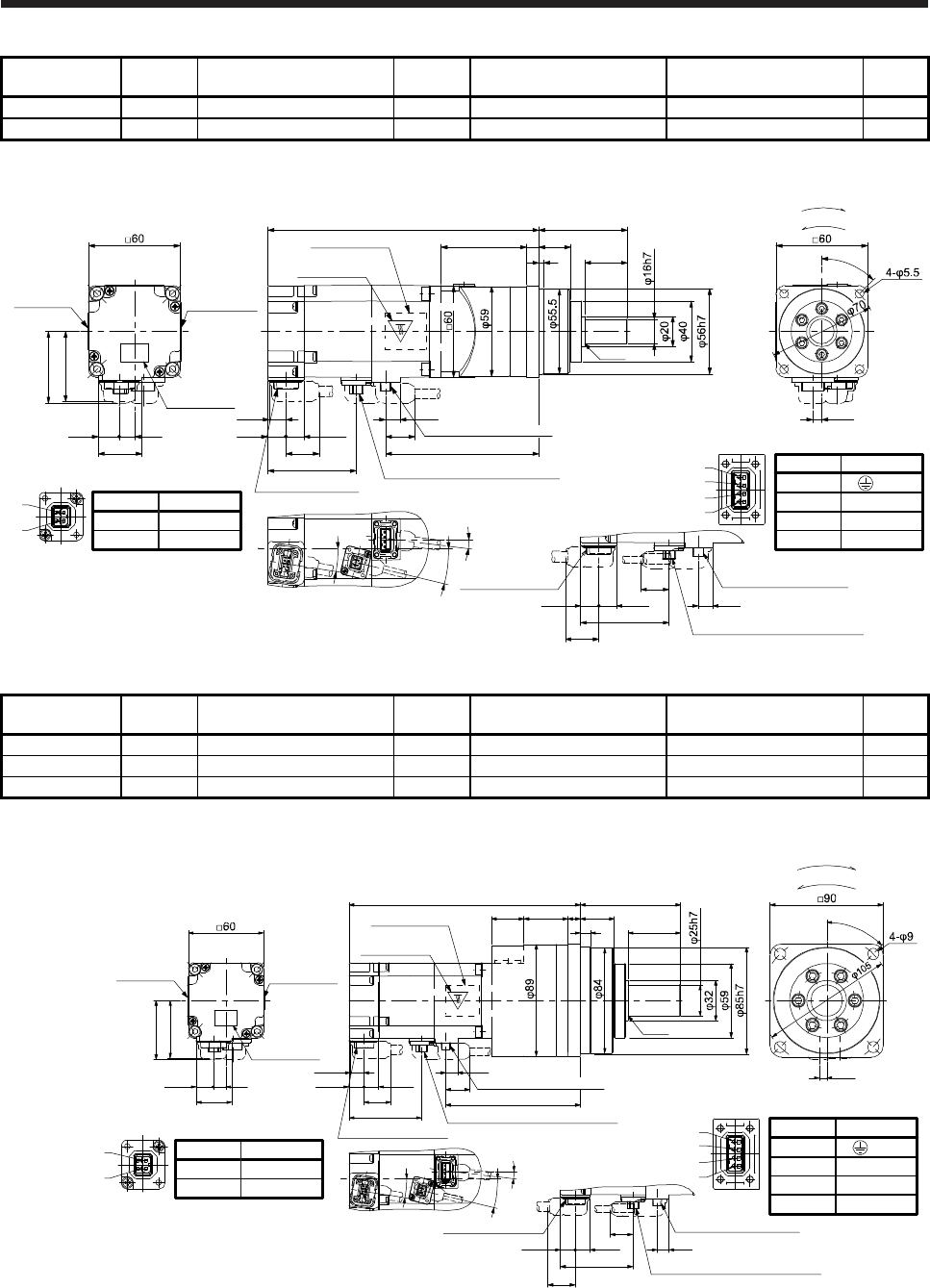
6. HG-MR SERIES/HG-KR SERIES
6 - 55
Model Output
[W] Reducer model Reduction
ratio
Brake static friction torque
[N•m]
Moment of inertia J
[× 10-4 kg•m2]
Mass
[kg]
HG-KR23BG7 200 HPG-14A-05-J2AZW-S 1/5 1.3 0.450 2.3
HG-KR23BG7 200 HPG-14A-11-J2AZX-S 1/11 1.3 0.446 2.4
[Unit: mm]
9°
7°
Caution plate
Bottom
177.4
100.4
11.711.8
10.9
19.2
9.5
Encoder connector
47.1
28.4
13.7 10
Caution plate
21.7
Caution plate
Motor plate
(Opposite side)
Motor plate
57.8
13.5°
Electromagnetic brake connector
58
28
56 21
3
8
R0.4
46
2
1Pin No.
1
2
Application
B2
B1
Electromagnetic brake connector
1
2
3
4
Pin No.
4
3
1
2
Application
W
V
U
(PE)
Power supply connector
BC41110*
Opposite-load side
9.511.8 11.7
57.8
Power supply connector
Encoder connector
21.7
18.3
Electromagnetic brake connector
5.9
45°
For reverse rotation command
For forward rotation command
Rotation direction
Power supply connector
Top
Bottom
Bottom
Top
Top
Model Output
[W] Reducer model Reduction
ratio
Brake static friction torque
[N•m]
Moment of inertia J
[× 10-4 kg•m2]
Mass
[kg]
HG-KR23BG7 200 HPG-20A-21-J2EKS-S 1/21 1.3 0.743 4.2
HG-KR23BG7 200 HPG-20A-33-J2ELS-S 1/33 1.3 0.696 4.2
HG-KR23BG7 200 HPG-20A-45-J2ELS-S 1/45 1.3 0.694 4.2
[Unit: mm]
5.9
45°
1035 27
80
8 42
26
R0.4
9°
7°
Caution plate
Bottom
184.4
107.4
11.711.8
10.9
19.2
9.5
Encoder connector
47.1
28.4
13.7 10
Caution plate
21.7
Caution plate
Motor plate
(Opposite side)
Motor plate
57.8
13.5°
Electromagnetic brake connector
46
Opposite-load side
9.5
11.8 11.7
57.8
Power supply connector
Encoder connector
21.7
18.3
Electromagnetic brake connector
For reverse rotation command
For forward rotation command
Rotation direction
2
1Pin No.
1
2
Application
B2
B1
Electromagnetic brake connector 1
2
3
4
Pin No.
4
3
1
2
Application
W
V
U
(PE)
Power supply connector
BC41111*
Power supply connector
Top
Bottom
Bottom
Top
Top
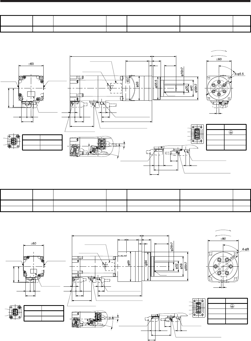
6. HG-MR SERIES/HG-KR SERIES
6 - 56
Model Output
[W] Reducer model Reduction
ratio
Brake static friction torque
[N•m]
Moment of inertia J
[× 10-4 kg•m2]
Mass
[kg]
HG-KR43BG7 400 HPG-14A-05-J2AZW-S 1/5 1.3 0.600 2.8
[Unit: mm]
199.1
Top
Motor plate
(Opposite side)
Caution plate
9°
7°
Caution plate
122.1
11.711.8
10.9
19.2
9.5
Power supply connector
Encoder connector
47.1
28.4
13.7 10
Caution plate
21.7
Motor plate
57.8
13.5°
Electromagnetic brake connector
856
58
45°
21
3 28
R0.4
5.9
46
2
1Pin No.
1
2
Application
B2
B1
Electromagnetic brake connector
1
2
3
4
Pin No.
4
3
1
2
Application
W
V
U
(PE)
Power supply connector
BC41112*
Opposite-load side
9.511.8 11.7
57.8
Power supply connector
Encoder connector
21.7
18.3
Electromagnetic brake connector
For reverse rotation command
For forward rotation command
Rotation direction
Bottom
Top
Bottom
Bottom
Top
Model Output
[W] Reducer model Reduction
ratio
Brake static friction torque
[N•m]
Moment of inertia J
[× 10-4 kg•m2]
Mass
[kg]
HG-KR43BG7 400 HPG-20A-11-J2EKS-S 1/11 1.3 0.977 4.7
HG-KR43BG7 400 HPG-20A-21-J2EKS-S 1/21 1.3 0.893 4.7
[Unit: mm]
Opposite-load side
9.511.8 11.7
57.8
Power supply
connector
Encoder connector
21.7
18.3
Electromagnetic brake connector
For reverse rotation command
For forward rotation command
Rotation direction
2
1Pin No.
1
2
Application
B2
B1
Electromagnetic brake connector 1
2
3
4
Pin No.
4
3
1
2
Application
W
V
U
(PE)
Power supply connector
BC41113*
206.1
Top
Motor plate
(Opposite side)
Caution plate
9°
7°
Caution plate
129.1
11.711.8
10.9
19.2
9.5
Power supply connector
Encoder connector
47.1
28.4
13.7 10
Caution plate
21.7
Motor plate
57.8
13.5°
Electromagnetic brake connector
R0.4
5.9
45°
80
428
27103526
46
Bottom
Top
Bottom
Top
Bottom
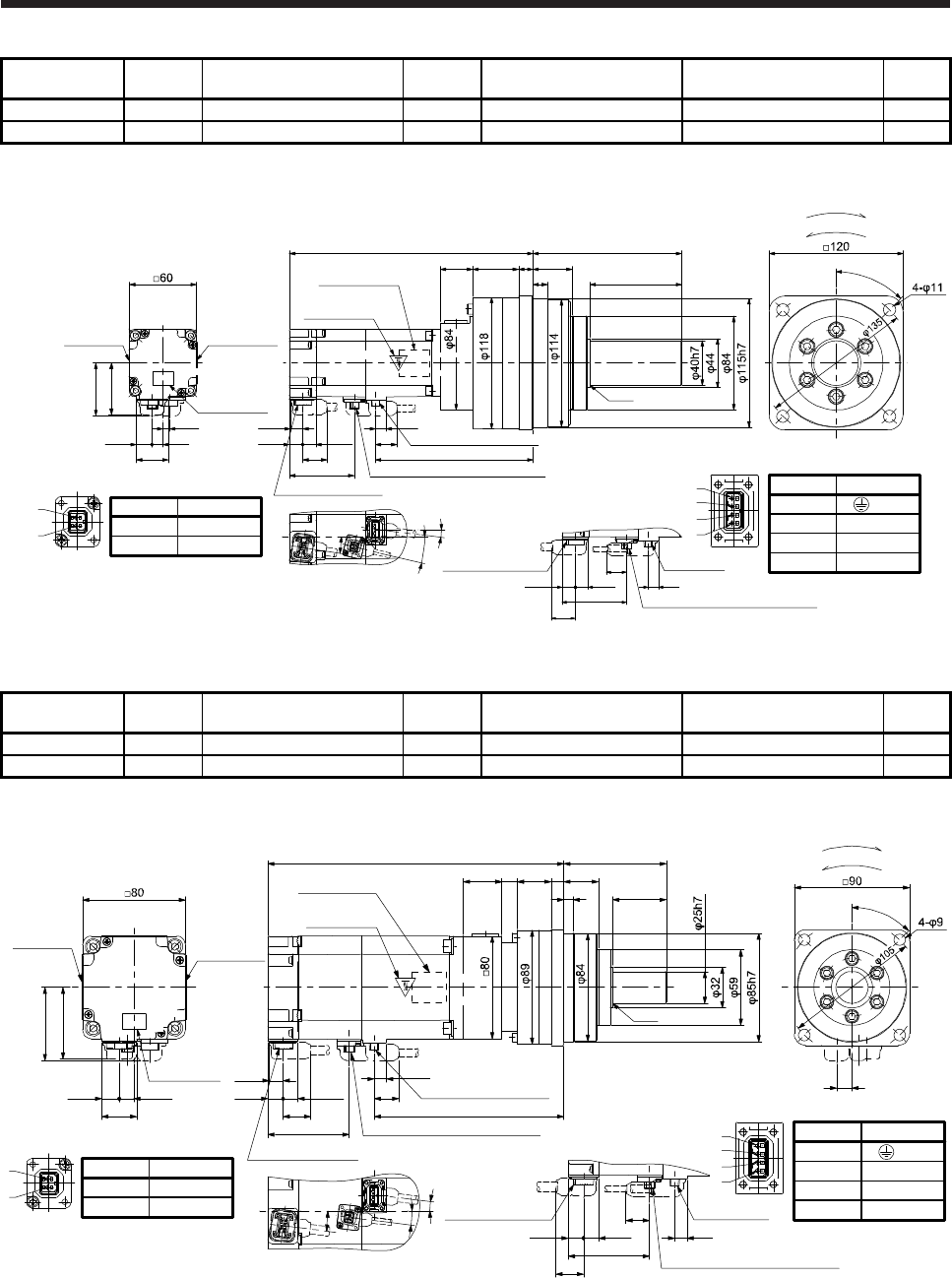
6. HG-MR SERIES/HG-KR SERIES
6 - 57
Model Output
[W] Reducer model Reduction
ratio
Brake static friction torque
[N•m]
Moment of inertia J
[× 10-4 kg•m2]
Mass
[kg]
HG-KR43BG7 400 HPG-32A-33-J2RLAS-S 1/33 1.3 0.949 7.8
HG-KR43BG7 400 HPG-32A-45-J2RLAS-S 1/45 1.3 0.940 7.8
[Unit: mm]
218.1
Top
Motor plate
(Opposite side)
Caution plate
R0.4
133
8213
351341
29
45°
9°
7°
Caution plate
141.1
11.711.8
10.9
19.2
9.5
Encoder connector
47.1
28.4
13.7 10
Caution plate
21.7
Motor plate
57.8
13.5°
Electromagnetic brake connector
5.9
46
2
1Pin No.
1
2
Application
B2
B1
Electromagnetic brake connector 1
2
3
4
Pin No.
4
3
1
2
Application
W
V
U
(PE)
Power supply connector
Opposite-load side
9.5
11.8 11.7
57.8
Power supply
connector
Encoder connector
21.7
18.3
Electromagnetic brake connector
BC41114*
For reverse rotation command
For forward rotation command
Rotation direction
Power supply connector
Bottom
Top
Bottom
Bottom
Top
Model Output
[W] Reducer model Reduction
ratio
Brake static friction torque
[N•m]
Moment of inertia J
[× 10-4 kg•m2]
Mass
[kg]
HG-KR73BG7 750 HPG-20A-05-J2FEOS-S 1/5 2.4 2.06 6.2
HG-KR73BG7 750 HPG-20A-11-J2FEPS-S 1/11 2.4 1.94 6.5
[Unit: mm]
Bottom
Top
230.3
Motor plate
(Opposite side)
Caution plate
7°
9.5
10.7
11.8 11.7 19.2
147.6
27.4
13.7 11.5
56
Power supply connector
Encoder connector
Caution plate
Caution plate
21.7
7°
Motor plate
7°
63.1 Electromagnetic brake connector
57.1
R0.4
80
428
2710261230
12
45°
Opposite-load side
Encoder connector
11.8 11.7
63.1
9.5
Power supply
connector
21.7
18.4
Electromagnetic brake connector
2
1Pin No.
1
2
Application
B2
B1
Electromagnetic brake connector
1
2
3
4
Pin No.
4
3
1
2
Application
W
V
U
(PE)
Power supply connector
BC41115*
For reverse rotation command
For forward rotation command
Rotation direction
Top
Bottom
Bottom
Top
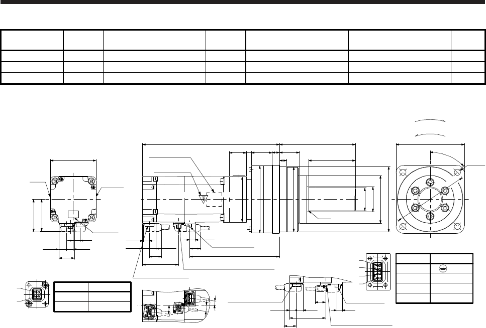
6. HG-MR SERIES/HG-KR SERIES
6 - 58
Model Output
[W] Reducer model Reduction
ratio
Brake static friction torque
[N•m]
Moment of inertia J
[× 10-4 kg•m2]
Mass
[kg]
HG-KR73BG7 750 HPG-32A-21-J2SEIS-S 1/21 2.4 2.14 9.6
HG-KR73BG7 750 HPG-32A-33-J2SEJS-S 1/33 2.4 1.91 9.6
HG-KR73BG7 750 HPG-32A-45-J2SEJS-S 1/45 2.4 1.90 9.6
[Unit: mm]
27.4
13.7 11.5
56
Caution
plate
Caution
plate
Motor
plate
57.1
□80
12
Pin No.
1
2
Application
B2
B1
Electromagnetic brake connector
2
1
13
351336
9
φ118
240.3
30
φ114
□80
Power supply
connector
Encoder connector
Electromagnetic brake connector
Caution plate
9.5
10.7
11.8 11.7 19.2
157.621.7
63.1
R0.4
133
82
φ40h7
φ44
φ84
φ115h7
4-φ11
45°
φ135
□120
Pin No.
4
3
1
2
Application
W
V
U
(PE)
Power supply connector
1
2
3
4
BC41116*
Opposite-load side
Encoder connector
11.8 11.7
63.1
9.5
Power supply
connector
21.7
18.4
Electromagnetic brake
connector
7°
7°
7°
Top
Bottom
Motor plate
(Opposite side)
For reverse rotation command
For forward rotation command
Rotation direction
Top
Bottom Bottom
Top
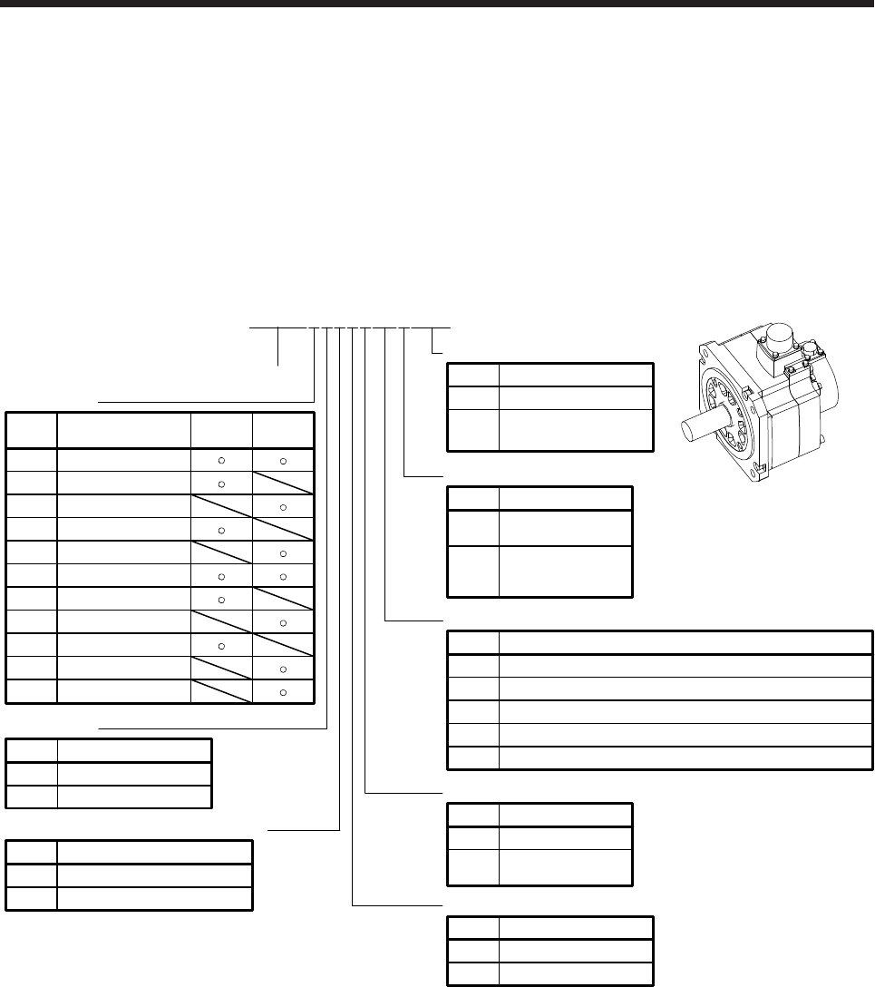
7. HG-SR SERIES
7 - 1
7. HG-SR SERIES
This chapter provides information on the servo motor specifications and characteristics. When using the HG-
SR series servo motor, always read the Safety Instructions in the beginning of this manual and chapters 1 to
5, in addition to this chapter.
7.1 Model code definition
The following describes what each block of a model name indicates. Not all combinations of the symbols are
available.
None None
Oil seal
Symbol Oil seal
(Note 2)
JWith
None None
Electromagnetic brake
Symbol Electromagnetic brake
BWith
Series
Shaft type
Symbol Shaft shape
None Standard
(straight shaft)
K(Note 1)
Keyway shaft
(with key)
Appearance
1
2
1000
Rated speed
Symbol Speed [r/min]
2000
None
Reducer
Symbol
G1 For general industrial machine (flange-mounting)
Flange-mounting flange output type for high precision application
Flange-mounting shaft output type for high precision application
Reducer
None
G5
G7
5 0.5
Rated output
Symbol Rated output [kW] 1000
[r/min] 2000
[r/min]
8 0.85
10 1.0
12 1.2
15 1.5
20 2.0
30 3.0
35 3.5
42 4.2
70 7.0
50 5.0
For general industrial machine (foot-mounting)G1H
HG-SR5 2 4 B JG1 K
None
4
3-phase 200 V AC to 240 V AC
Power supply voltage of servo amplifier
Symbol Voltage
3-phase 380 V AC to 480 V AC
W0C
None Standard
Special specification
Symbol Special specification
(Note 3)
W0C Servo motor with
functional safety
Note 1. The key is packed only with the geared servo motor of flange mounting shaft-output type for high precision applications.
2. For details, contact your local sales office.
3. Refer to section 1.5 for details.
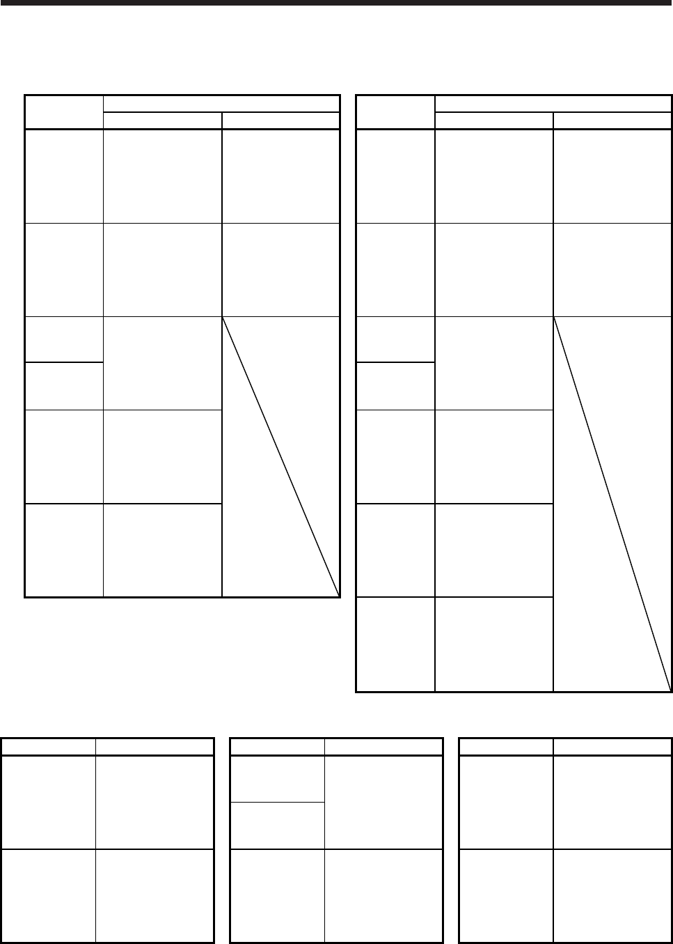
7. HG-SR SERIES
7 - 2
7.2 Combination list of servo motors and servo amplifiers
(1) Compatible with 3-phase 200 V AC
Servo motor Servo amplifier Servo motor Servo amplifier
MR-J4 1-axis MR-J4 2-axis MR-J4 1-axis MR-J4 2-axis
HG-SR51
MR-J4-60A
MR-J4-60A-RJ
MR-J4-60B
MR-J4-60B-RJ
MR-J4-60B-RJ010
MR-J4-60B-RJ020
MR-J4W2-77B
MR-J4W2-1010B
HG-SR52
MR-J4-60A
MR-J4-60A-RJ
MR-J4-60B
MR-J4-60B-RJ
MR-J4-60B-RJ010
MR-J4-60B-RJ020
MR-J4W2-77B
MR-J4W2-1010B
HG-SR81
MR-J4-100A
MR-J4-100A-RJ
MR-J4-100B
MR-J4-100B-RJ
MR-J4-100B-RJ010
MR-J4-100B-RJ020
MR-J4W2-1010B
HG-SR102
MR-J4-100A
MR-J4-100A-RJ
MR-J4-100B
MR-J4-100B-RJ
MR-J4-100B-RJ010
MR-J4-100B-RJ020
MR-J4W2-1010B
HG-SR121
MR-J4-200A
MR-J4-200A-RJ
MR-J4-200B
MR-J4-200B-RJ
MR-J4-200B-RJ010
MR-J4-200B-RJ020
HG-SR152
MR-J4-200A
MR-J4-200A-RJ
MR-J4-200B
MR-J4-200B-RJ
MR-J4-200B-RJ010
MR-J4-200B-RJ020
HG-SR201
HG-SR202
HG-SR301
MR-J4-350A
MR-J4-350A-RJ
MR-J4-350B
MR-J4-350B-RJ
MR-J4-350B-RJ010
MR-J4-350B-RJ020
HG-SR352
MR-J4-350A
MR-J4-350A-RJ
MR-J4-350B
MR-J4-350B-RJ
MR-J4-350B-RJ010
MR-J4-350B-RJ020
HG-SR421
MR-J4-500A
MR-J4-500A-RJ
MR-J4-500B
MR-J4-500B-RJ
MR-J4-500B-RJ010
MR-J4-500B-RJ020
HG-SR502
MR-J4-500A
MR-J4-500A-RJ
MR-J4-500B
MR-J4-500B-RJ
MR-J4-500B-RJ010
MR-J4-500B-RJ020
HG-SR702
MR-J4-700A
MR-J4-700A-RJ
MR-J4-700B
MR-J4-700B-RJ
MR-J4-700B-RJ010
MR-J4-700B-RJ020
(2) Compatible with 3-phase 400 V AC
Servo motor Servo amplifier Servo motor Servo amplifier Servo motor Servo amplifier
HG-SR524
MR-J4-60A4
MR-J4-60A4-RJ
MR-J4-60B4
MR-J4-60B4-RJ
MR-J4-60B4-RJ010
MR-J4-60B4-RJ020
HG-SR1524
MR-J4-200A4
MR-J4-200A4-RJ
MR-J4-200B4
MR-J4-200B4-RJ
MR-J4-200B4-RJ010
MR-J4-200B4-RJ020
HG-SR5024
MR-J4-500A4
MR-J4-500A4-RJ
MR-J4-500B4
MR-J4-500B4-RJ
MR-J4-500B4-RJ010
MR-J4-500B4-RJ020
HG-SR2024
HG-SR1024
MR-J4-100A4
MR-J4-100A4-RJ
MR-J4-100B4
MR-J4-100B4-RJ
MR-J4-100B4-RJ010
MR-J4-100B4-RJ020
HG-SR3524
MR-J4-350A4
MR-J4-350A4-RJ
MR-J4-350B4
MR-J4-350B4-RJ
MR-J4-350B4-RJ010
MR-J4-350B4-RJ020
HG-SR7024
MR-J4-700A4
MR-J4-700A4-RJ
MR-J4-700B4
MR-J4-700B4-RJ
MR-J4-700B4-RJ010
MR-J4-700B4-RJ020
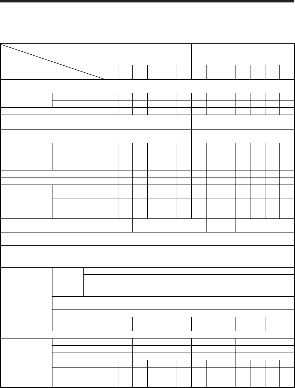
7. HG-SR SERIES
7 - 3
7.3 Standard specifications
7.3.1 Standard specifications list
Servo motor
Item
HG-SR 1000 r/min series
(Compatible with 3-phase 200 V AC,
medium inertia/medium capacity)
HG-SR 2000 r/min series
(Compatible with 3-phase 200 V AC,
medium inertia/medium capacity)
51(B) 81(B) 121
(B)
201
(B)
301
(B)
421
(B) 52(B) 102
(B)
152
(B)
202
(B)
352
(B)
502
(B)
702
(B)
Power supply capacity Refer to "Power supply equipment capacity and generated loss of servo amplifiers" in
Servo Amplifier Instruction Manual.
Continuous running
duty (Note 1)
Rated output [kW] 0.5 0.85 1.2 2.0 3.0 4.2 0.5 1.0 1.5 2.0 3.5 5.0 7.0
Rated torque [N•m] 4.8 8.1 11.5 19.1 28.6 40.1 2.4 4.8 7.2 9.5 16.7 23.9 33.4
Maximum torque (Note 10) [N•m] 14.3 24.4 34.4 57.3 85.9 120 7.2 14.3 21.5 28.6 50.1 71.6 100
Rated speed (Note 1) [r/min] 1000 2000
Maximum speed (Note 10) [r/min] 1500 3000
Instantaneous permissible speed
(Note 10) [r/min] 1725 3450
Power rate at
continuous rated
torque
Standard [kW/s] 19.7 41.2 28.1 46.4 82.3 107 7.85 19.7 32.1 19.5 35.5 57.2 74.0
With an
electromagnetic brake
[kW/s]
16.5 36.2 23.2 41.4 75.3 99.9 6.01 16.5 28.2 16.1 31.7 52.3 69.4
Rated current [A] 2.8 5.2 7.1 9.4 13 19 2.9 5.6 9.4 9.6 14 22 26
Maximum current [A] 9.0 17 23 30 42 61 9.0 17 29 31 45 70 83
Moment of inertia J
(Note 3)
Standard
[× 10-4 kg•m2] 11.6 16.0 46.8 78.6 99.7 151 7.26 11.6 16.0 46.8 78.6 99.7 151
With an
electromagnetic brake
[× 10-4 kg•m2]
13.8 18.2 56.5 88.2 109 161 9.48 13.8 18.2 56.5 88.2 109 161
Recommended load to motor inertia ratio
(Note 2, 10)
17 times
or less 15 times or less 17 times
or less 15 times or less
Speed/position detector 22-bit encoder common to absolute position/incremental systems
(resolution per servo motor revolution: 4194304 pulses/rev)
Oil seal None (Note 11)
Insulation class 155 (F)
Structure Totally-enclosed, natural-cooling (IP rating: IP67 (Note 4, 9))
Environment (Note 5)
Ambient
temperature
Operation 0 °C to 40 °C (non-freezing)
Storage -15 °C to 70 °C (non-freezing)
Ambient
humidity
Operation 80 %RH or less (non-condensing)
Storage 90 %RH or less (non-condensing)
Ambience Indoors (no direct sunlight), free from corrosive gas,
flammable gas, oil mist, dust, and dirt
Altitude Max. 1000 m above sea level
Vibration resistance
(Note 6)
X, Y:
24.5 m/s2
X: 24.5 m/s2
Y: 49 m/s2
X: 24.5 m/s2
Y: 29.4 m/s2X, Y: 24.5 m/s2 X: 24.5 m/s2
Y: 49 m/s2
X: 24.5 m/s2
Y: 29.4 m/s2
Vibration rank (Note 7) V10
Permissible load for
the shaft
(Note 8)
L [mm] 55 79 55 79
Radial [N] 980 2058 980 2058
Thrust [N] 490 980 490 980
Mass (Note 3)
Standard [kg] 6.2 7.3 11 16 20 27 4.8 6.2 7.3 11 16 20 27
With an
electromagnetic brake
[kg]
8.2 9.3 17 22 26 33 6.7 8.2 9.3 17 22 26 33
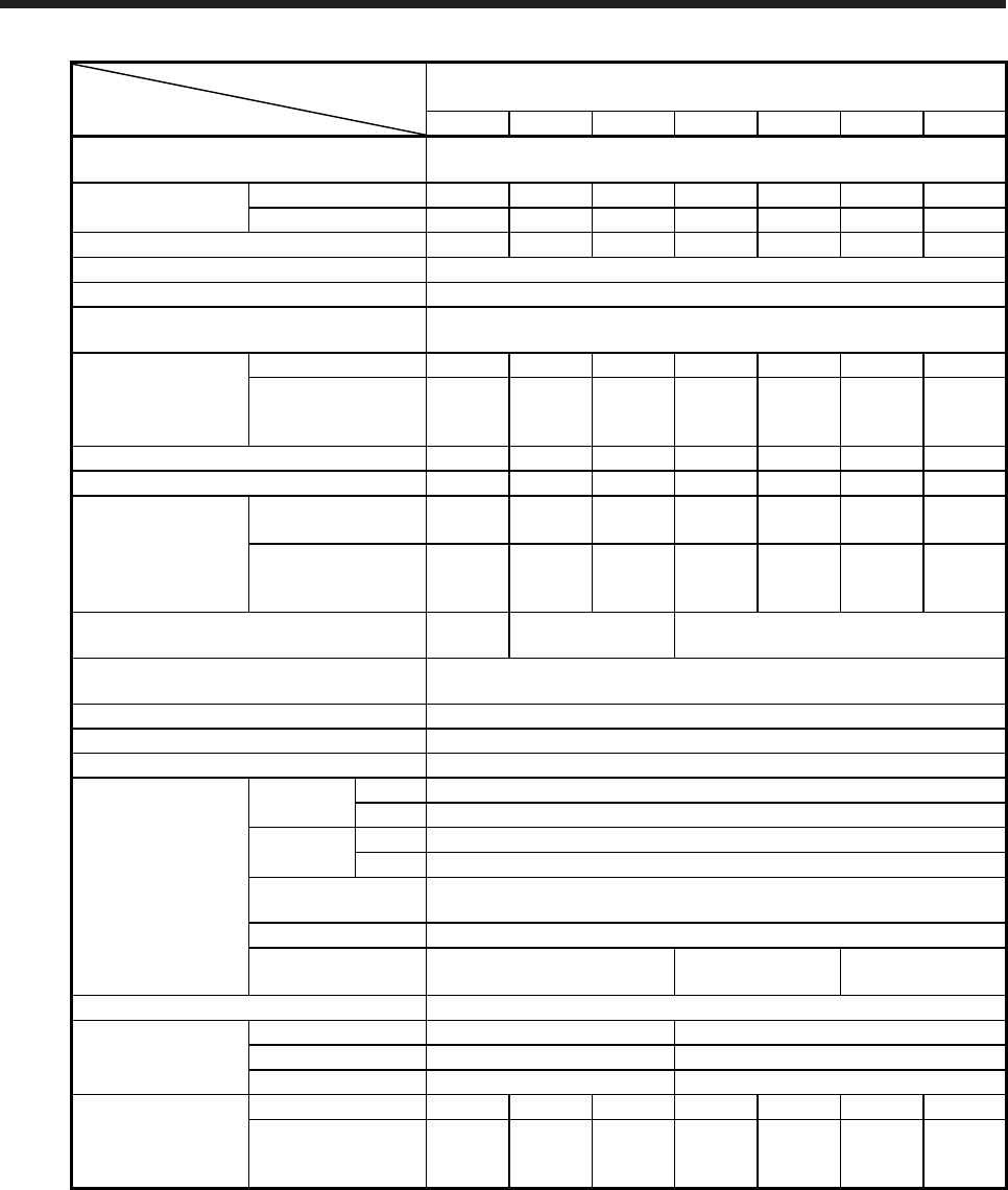
7. HG-SR SERIES
7 - 4
Servo motor
Item
HG-SR series
(3-phase 400 V AC compatible, medium inertia/medium capacity)
524(B) 1024(B) 1524(B) 2024(B) 3524(B) 5024(B) 7024(B)
Power supply capacity Refer to "Power supply equipment capacity and generated loss of servo
amplifiers" in Servo Amplifier Instruction Manual.
Continuous running
duty (Note 1)
Rated output [kW] 0.5 1.0 1.5 2.0 3.5 5.0 7.0
Rated torque [N•m] 2.4 4.8 7.2 9.5 16.7 23.9 33.4
Maximum torque (Note 10) [N•m] 7.2 14.3 21.5 28.6 50.1 71.6 100
Rated speed (Note 1) [r/min] 2000
Maximum speed (Note 10) [r/min] 3000
Instantaneous permissible speed
(Note 10) [r/min] 3450
Power rate at
continuous rated
torque
Standard [kW/s] 7.85 19.7 32.1 19.5 35.5 57.2 74.0
With an
electromagnetic brake
[kW/s]
6.01 16.5 28.2 16.1 31.7 52.3 69.4
Rated current [A] 1.5 2.8 4.7 4.9 7.0 11 13
Maximum current [A] 4.5 8.9 17 17 27 42 59
Moment of inertia J
(Note 3)
Standard
[× 10-4 kg•m2]7.26 11.6 16.0 46.8 78.6 99.7 151
With an
electromagnetic brake
[× 10-4 kg•m2]
9.48 13.8 18.2 56.5 88.2 109 161
Recommended load to motor inertia ratio
(Note 2, 10)
15 times
or less 17 times or less 15 times or less
Speed/position detector 22-bit encoder common to absolute position/incremental
(resolution per servo motor revolution: 4194304 pulses/rev)
Oil seal None (Note 11)
Insulation class 155 (F)
Structure Totally-enclosed, natural-cooling (IP rating: IP67 (Note 4, 9))
Environment (Note 5)
Ambient
temperature
Operation 0 ˚C to 40 ˚C (non-freezing)
Storage -15 ˚C to 70 ˚C (non-freezing)
Ambient
humidity
Operation 80 %RH or less (non-condensing)
Storage 90 %RH or less (non-condensing)
Ambience Indoors (no direct sunlight),
free from corrosive gas, flammable gas, oil mist, dust, and dirt
Altitude 1000 m or less above sea level
Vibration resistance
(Note 6) X, Y: 24.5 m/s2 X: 24.5 m/s2
Y: 49 m/s2
X: 24.5 m/s2
Y: 29.4 m/s2
Vibration rank (Note 7) V10
Permissible load for
the shaft (Note 8)
L [mm] 55 79
Radial [N] 980 2058
Thrust [N] 490 980
Mass (Note 3)
Standard [kg] 4.8 6.2 7.3 11 16 20 27
With an
electromagnetic brake
[kg]
6.7 8.2 9.3 17 22 26 33
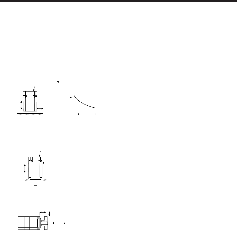
7. HG-SR SERIES
7 - 5
Note 1. When the power supply voltage drops, the output and the rated speed cannot be guaranteed.
2. If the load to motor inertia ratio exceeds the indicated value, contact your local sales office.
3. Refer to the dimensions for the geared servo motor.
4. Except for the shaft-through portion. IP classifies the degrees of protection provided against the intrusion of solid objects and
water in electrical enclosures.
5. In the environment where the servo motor is exposed to oil mist, oil, or water, the servo motor of the standard specifications
may not be usable. Please contact your local sales office.
6. The following figure shows the vibration directions. The value is the one at the part that indicates the maximum value (normally
the opposite to load-side bracket). When the servo motor stops, fretting is likely to occur at the bearing. Therefore, suppress
the vibration to about half of the permissible value.
Y
X
Servo motor
Vibration
(both amplitudes) [ m]
Speed [r/min]
0 1000 2000 3000
10
100
1000
Vibration amplitude
7. V10 indicates that the amplitude of a single servo motor is 10 μm or less. The following figure shows the servo motor mounting
position for measurement and the measuring position.
Servo motor
Top
Bottom
Measuring position
8. The following shows permissible load for the shaft. Do not subject the shaft to load greater than the value in the specifications
list. The value assumes that the load is applied independently.
L
Radial load
Thrust load
L: Distance from flange mounting surface to load center
9. For the geared servo motor, the reducer area is IP44-equivalent.
10. Refer to section 7.6 for the geared servo motor.
11. The servo motors with an oil seal are also available. For details, contact your local sales office.
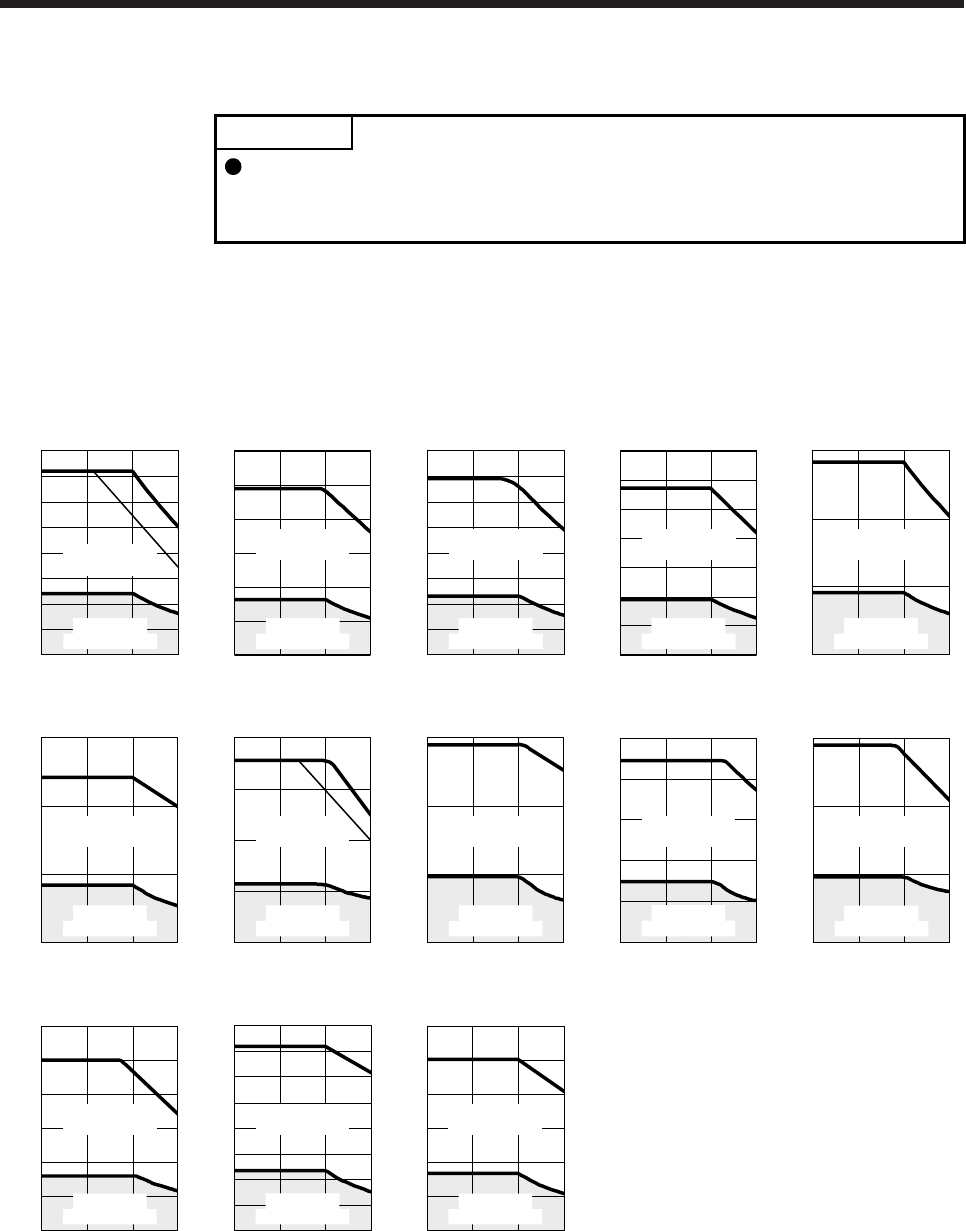
7. HG-SR SERIES
7 - 6
7.3.2 Torque characteristics
POINT
For the system where the unbalanced torque occurs, such as a vertical axis
system, the unbalanced torque of the machine should be kept at 70% or less of
the rated torque.
(1) 3-phase 200 V AC
When the power supply input of the servo amplifier is 3-phase 200 V AC or 1-phase 230 V AC, the
torque characteristic is indicated by the heavy line. For the 1-phase 200 V AC power supply, part of the
torque characteristic is indicated by the thin line. HG-SR51 and HG-SR52 support single-phase power
supply.
500 1000 1500
[HG-SR51]
0
4
12
16
8
14
10
6
2
0
Speed [r/min]
Continuous
running range
Short-duration
running range
Torque [N•m]
[HG-SR81]
1000 1500500
20
30
10
25
15
5
0
0
Speed [r/min]
Continuous
running range
Short-duration
running range
Torque [N•m]
[HG-SR121]
1000 1500500
30
40
15
35
20
10
25
5
0
0
Speed [r/min]
Continuous
running range
Short-duration
running range
Torque [N•m]
[HG-SR201]
1000 1500500
10
50
70
30
60
40
20
0
0
Speed [r/min]
Continuous
running range
Short-duration
running range
Torque [N•m]
[HG-SR301]
1000 1500500
30
90
60
0
0
Speed [r/min]
Continuous
running range
Short-duration
running range
Torque [N•m]
[HG-SR421]
1000 15005000
100
150
50
0
Speed [r/min]
Continuous
running range
Short-duration
running range
Torque [N•m]
[HG-SR52]
1000 2000 3000
2
6
8
4
0
0
Speed [r/min]
Continuous
running range
Short-duration
running range
Torque [N•m]
[HG-SR102]
1000 2000 3000
5
10
15
0
0
Speed [r/min]
Continuous
running range
Short-duration
running range
Torque [N•m]
[HG-SR152]
1000 2000 3000
5
15
25
20
10
0
0
Speed [r/min]
Continuous
running range
Short-duration
running range
Torque [N•m]
[HG-SR202]
1000 2000 3000
10
20
30
0
0
Speed [r/min]
Continuous
running range
Short-duration
running range
Torque [N•m]
[HG-SR352]
1000 2000 3000
20
40
60
10
30
50
0
0
Speed [r/min]
Continuous
running range
Short-duration
running range
Torque [N•m]
[HG-SR502]
2000 30001000
80
0
0
60
40
70
50
30
20
10
Speed [r/min]
Torque [N•m]
Continuous
running range
Short-duration
running range
0 2000 30001000
[HG-SR702]
80
120
40
100
60
20
0
Speed [r/min]
Continuous
running range
Short-duration
running range
Torque [N•m]
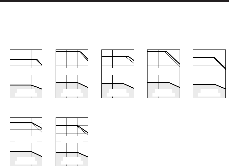
7. HG-SR SERIES
7 - 7
(2) 3-phase 400 V AC
When the power supply input of the servo amplifier are 3-phase 400 V AC, the torque characteristic is
indicated by the heavy line. For the 3-phase 380 V AC power supply, part of the torque characteristic is
indicated by the thin line.
[HG-SR524]
1000 2000 30000
0
6
9
3
Speed [r/min]
Continuous
running range
Short-duration
running range
Torque [N•m]
[HG-SR1024]
1000 2000 30000
0
10
15
5
Speed [r/min]
Continuous
running range
Short-duration
running range
Torque [N•m]
[HG-SR1524]
1000 2000 30000
0
16
24
8
Speed [r/min]
Continuous
running range
Short-duration
running range
Torque [N•m]
[HG-SR2024]
1000 2000 30000
0
20
30
10
Speed [r/min]
Continuous
running range
Short-duration
running range
Torque [N•m]
[HG-SR3524]
1000 2000 30000
0
40
60
20
Speed [r/min]
Continuous
running range
Short-duration
running range
Torque [N•m]
[HG-SR5024]
1000 2000 30000
0
60
80
40
70
50
30
20
10
Speed [r/min]
Continuous
running range
Short-duration
running range
Torque [N•m]
[HG-SR7024]
1000 2000 30000
0
80
120
40
100
60
20
Speed [r/min]
Continuous
running range
Short-duration
running range
Torque [N•m]
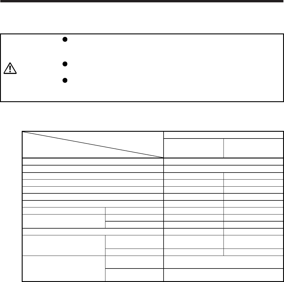
7. HG-SR SERIES
7 - 8
7.4 Electromagnetic brake characteristics
CAUTION
The electromagnetic brake is provided to prevent a drop at a power failure or
servo alarm occurrence during vertical drive or to hold a shaft at a stop. Do not
use it for normal braking (including braking at servo-lock).
Before operating the servo motor, be sure to confirm that the electromagnetic
brake operates properly.
The operation time of the electromagnetic brake differs depending on the power
supply circuit you use. Be sure to check the operation delay time with a real
machine.
The characteristics of the electromagnetic brake provided for the servo motor with an electromagnetic brake
are indicated below.
Servo motor
Item
HG-SR series
51B/81B/52(4)B/
102(4)B/152(4)B
121B/201B/301B/421B/
202(4)B/352(4)B/502(4)B/
702(4)B
Type (Note 1) Spring actuated type safety brake
Rated voltage (Note 4) 24 V DC 0
-10%
Power consumption [W] at 20 °C 20 34
Coil resistance (Note 6) [Ω] 29.0 16.8
Inductance (Note 6) [H] 0.80 1.10
Brake static friction torque [N•m] 8.5 44
Release delay time (Note 2) [s] 0.04 0.1
Braking delay time (Note 2) [s] DC off 0.03 0.03
Permissible braking work Per braking [J] 400 4500
Per hour [J] 4000 45000
Brake looseness at servo motor shaft (Note 5) [degrees] 0.2 to 0.6 0.2 to 0.6
Brake life (Note 3)
Number of brakings
[times] 20000 20000
Work per braking [J] 200 1000
Selection example of surge absorbers
to be used
(Note 7, 8)
For the suppressed
voltage 125 V TND20V-680KB
For the suppressed
voltage 350 V TND10V-221KB
Note 1. There is no manual release mechanism. When it is necessary to hand-turn the servo motor shaft for machine
centering, etc., use a separate 24 V DC power supply to release the brake electrically.
2. The value for initial on gap at 20 °C.
3. The brake gap will increase as the brake lining wears, but the gap is not adjustable.
The brake life indicated is the number of braking cycles after which adjustment will be required.
4.
A
lways prepare a power supply exclusively used for the electromagnetic brake.
5. These are design values. These are not guaranteed values.
6. These are measured values. These are not guaranteed values.
7. Select the electromagnetic brake control relay properly, considering the characteristics of the electromagnetic brake
and surge absorber. When you use a diode for a surge absorber, the electromagnetic braking time will be longer.
8. Manufactured by Nippon Chemi-Con Corporation.
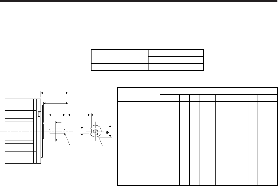
7. HG-SR SERIES
7 - 9
7.5 Servo motors with special shafts
The servo motors with special shafts indicated by the symbol (K) in the table are available. K is the symbol
attached to the servo motor model names.
Servo motor Shaft shape
Key shaft (without key)
HG-SR_(B)K K
Variable dimension table [Unit: mm]
S
QL
A
A
QK
Q
R
W
U
r Y
Shaft section view A-A
Servo motor Variable dimensions
S R Q W QK QL U r Y
HG-SR51(B)K
HG-SR81(B)K
HG-SR52(4)(B)K
HG-SR102(4)(B)K
HG-SR152(4)(B)K
24h6 55 50 80
-0.036 36 5
4
+0.2
0 4
M8
Screw
hole
depth
20
HG-SR121(B)K
HG-SR201(B)K
HG-SR301(B)K
HG-SR421(B)K
HG-SR202(4)(B)K
HG-SR352(4)(B)K
HG-SR502(4)(B)K
HG-SR702(4)(B)K
35 +0.010
079 75 10 0
-0.036 55 5 5+0.2
0 5
M8
Screw
hole
depth
20
Key shaft (without key)
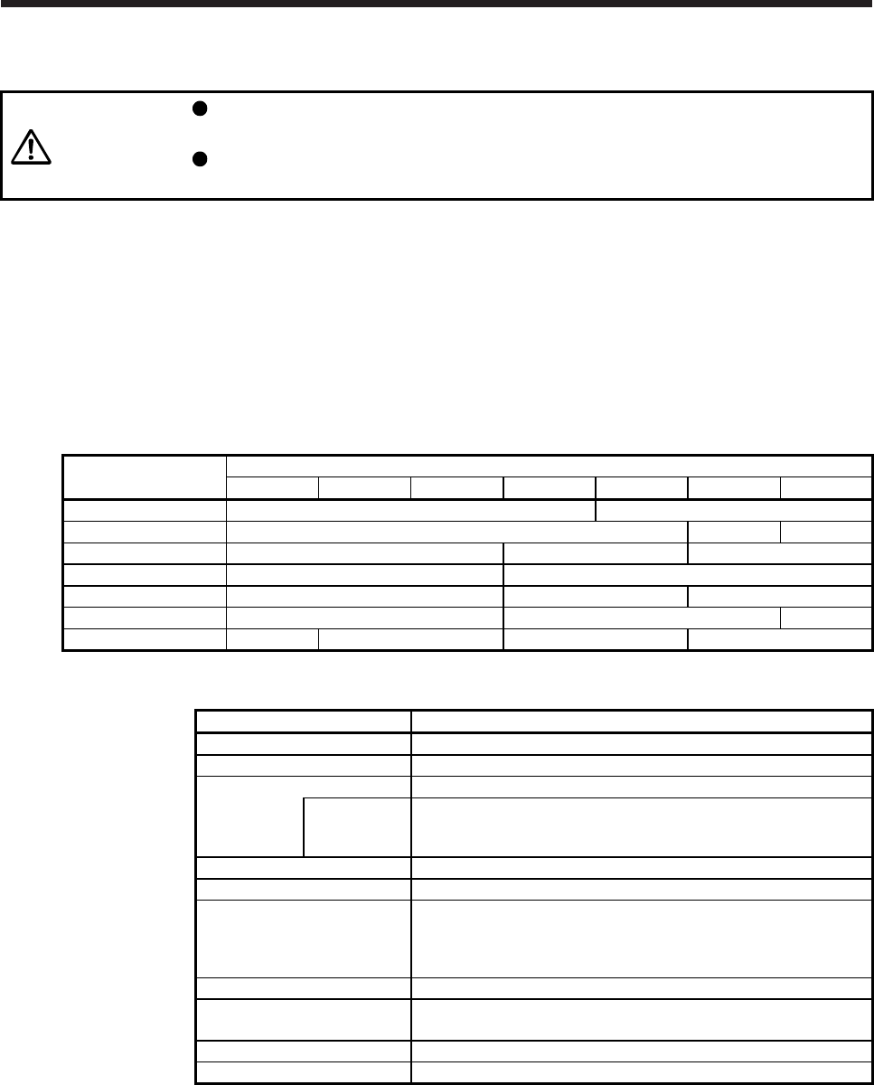
7. HG-SR SERIES
7 - 10
7.6 Geared servo motors
CAUTION
Geared servo motors must be mounted in the specified direction. Otherwise, it
can leak oil, leading to a fire or malfunction.
For the geared servo motor, remove the oil before transportation and installation.
Tipping over the reducer filled with oil can cause oil leakage.
Servo motors are available with a reducer designed for general industrial machines and high precision
applications.
Servo motors with an electromagnetic brake are also available.
7.6.1 For general industrial machines (G1/G1H)
(1) Reduction ratio
The following table indicates the reduction ratios and reducer frame numbers of the geared servo motor
for general industrial machines.
Servo motor Reduction ratio
1/6 1/11 1/17 1/29 1/35 1/43 1/59
HG-SR52(4)(B)G1(H) 6100 6120
HG-SR102(4)(B)G1(H) 6120 6130 6160
HG-SR152(4)(B)G1(H) 6120 6130 6160
HG-SR202(4)(B)G1(H) 6120 6165
HG-SR352(4)(B)G1(H) 6135 6165 6175
HG-SR502(4)(B)G1(H) 6165 6180 6185
HG-SR702(4)(B)G1(H) 6165 6170 6180 6195
(2) Specifications
Item Description
Mounting method Refer to (2) (b) in this section.
Mounting direction Refer to (2) (b) in this section.
Lubrication
method
Refer to (2) (b)/(c) in this section.
Recommended
products
(Note 1)
Refer to (2) (c) in this section.
Output shaft rotating direction Opposite direction to the servo motor output shaft
Backlash (Note 5) 40 minutes to 2 ° at reducer output shaft (Note 4)
Permissible load inertia
moment ratio (when converting
into the servo motor shaft)
(Note 2)
4 times or less
Maximum torque Three times of the servo motor rated torque
Maximum speed
(servo motor shaft) Refer to (2) (a) in this section.
IP rating (reducer area) IP44 equivalent
Reducer efficiency (Note 3) 85% to 94%
Note 1.
A
lready packed with grease.
2. If the above indicated value is exceeded, please contact your local sales office.
3. The reducer efficiency differs depending on the reduction ratio. Also, it changes depending on
the operating conditions such as the output torque, speed and rotation, temperature, etc. The
numerical value in the table is a typical value in the rated torque, rated speed and rotation and
typical temperature, and not a guaranteed value.
4. These values are design values and not guaranteed values.
5. The backlash can be converted: 1 min = 0.0167 °
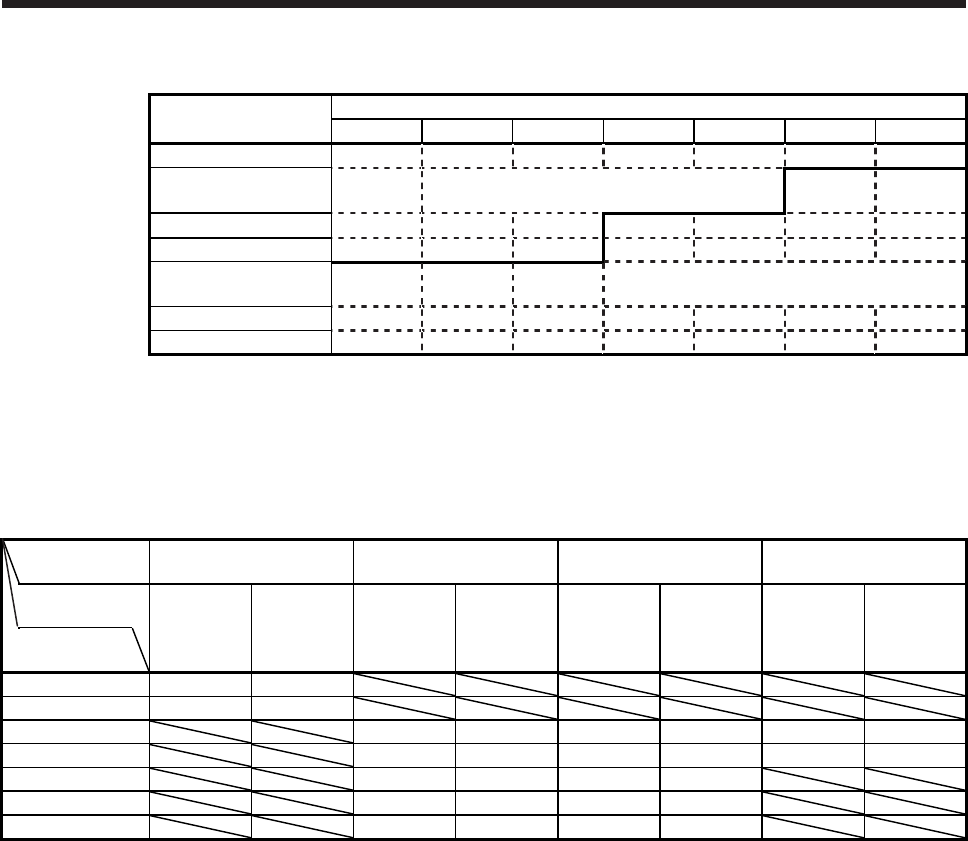
7. HG-SR SERIES
7 - 11
(a) Maximum speed
Servo motor Reduction ratio
1/6 1/11 1/17 1/29 1/35 1/43 1/59
HG-SR52(4)(B)G1(H)
HG-SR102(4)(B)G1(H) 3000 r/min (permissible instantaneous speed:
3450 r/min)
HG-SR152(4)(B)G1(H)
HG-SR202(4)(B)G1(H)
HG-SR352(4)(B)G1(H) 2000 r/min (permissible instantaneous speed:
2300 r/min)
HG-SR502(4)(B)G1(H)
HG-SR702(4)(B)G1(H)
(b) Lubrication method and mounting direction
Oil lubrication cannot be used in applications where the servo motor will move. Specify grease
lubrication.
For grease lubrication, the reducer is already grease-packed. For oil lubrication, pack the reducer
with oil on the customer side.
Mounting
direction Shaft any direction Shaft horizontal Shaft downward Shaft upward
Reducer
model CNHM CNVM CHHM CHVM CVHM CVVM CWHM CWVM
Reducer
frame No. (Foot-
mounting)
(Flange-
mounting)
(Foot-
mounting)
(Flange-
mounting)
(Foot-
mounting)
(Flange-
mounting)
(Foot-
mounting)
(Flange-
mounting)
6100 Grease Grease
6120 Grease Grease
6130/6135 (Note) Oil (Note) Oil (Note) Oil (Note) Oil Grease Grease
6160/6165 (Note) Oil (Note) Oil (Note) Oil (Note) Oil Grease Grease
6170/6175 Oil Oil Oil Oil
6180/6185 Oil Oil Oil Oil
6195 Oil Oil Oil Oil
Note. Grease-lubricated type is also available as optional products.
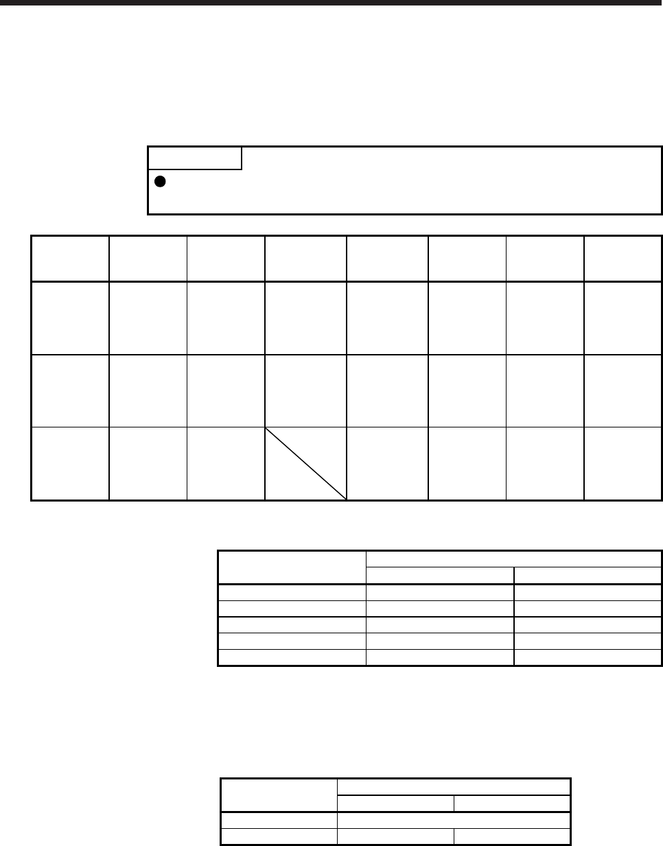
7. HG-SR SERIES
7 - 12
(c) Recommended lubricants
1) Grease
Albania Grease RA (Shell)
2) Lubricating oil
POINT
Since the oil-lubricated models are shipped without oil, make sure to fill oil up to
the upper red line of the oil gauge before operation.
Ambient
temperature
[°C]
COSMO OIL JX Nippon Oil
& Energy
Idemitsu
Kosan Shell Esso Exxon Mobil Japan Energy
-10 to 5 COSMO
GEAR SE68
BONNOC
M68
DIAMOND
GEAR LUBE
SP68
DAPHNE
SUPER GEAR
OIL 68
Omala Oils 68 SPARTAN
EP68
Mobilgear
626
(ISOVG68)
JOMO
Reductus 68
0 to 35 COSMO
GEAR
SE100/150
BONNOC
M100/150
DIAMOND
GEAR LUBE
SP100/150
DAPHNE
SUPER GEAR
OIL 100/150
Omala Oils
100/150
SPARTAN
EP100/150
Mobilgear
627/629
(ISOVG100/1
50)
JOMO
Reductus
100/150
30 to 50 COSMO
GEAR
SE200/320/4
60
BONNOC
M200 to 460
DIAMOND
GEAR LUBE
SP220 to 460
Omala Oils
200 to 460
SPARTAN
EP220 to 460
Mobilgear
630 to 634
(ISOVG220 to
460)
JOMO
Reductus 200
to 460
Lubricating oil fill amount
Reducer frame No. Fill amount [L]
Horizontal type Vertical type
6130/6135 0.7 1.1
6160/6165 1.4 1.0
6170/6175 1.9 1.9
6180/6185 2.5 2.0
6195 4.0 2.7
(d) Changing intervals
1) Grease
Maintenance-free. (Limited to the case where the grease-lubricated type is standard)
2) Lubricating oil
Changing intervals Operation hours per day
Less than 10 hours 10 hours to 24 hours
First time 500 hours
Second time and later Half year 2500 hours
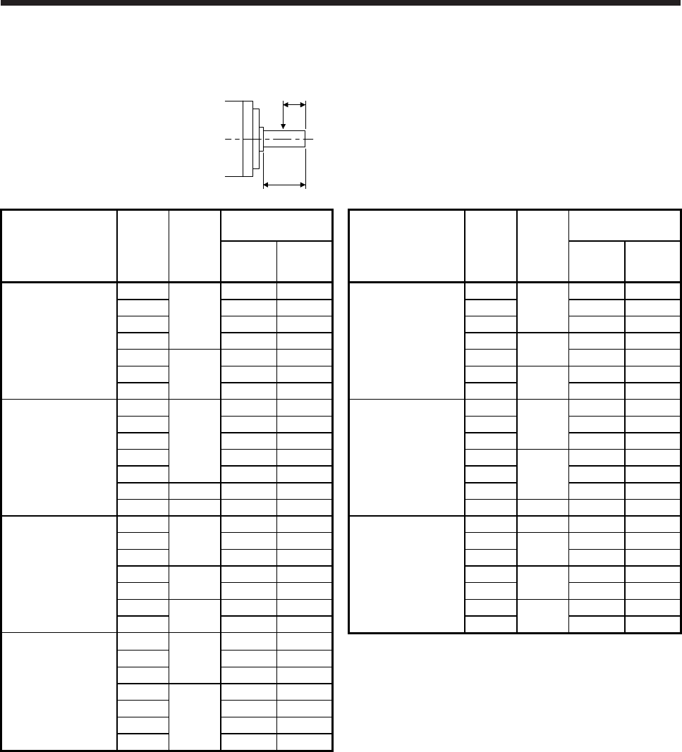
7. HG-SR SERIES
7 - 13
(3) Permissible loads of servo motor shaft
The permissible radial load in the table is the value measured at the center of the reducer output shaft.
Q: Length of axis (Refer to section 7.7.3 to 7.7.6.)
Q/2
Q
Servo motor Reduction
ratio
Reducer
frame
No.
Permissible load
(Note)
Servo motor Reduction
ratio
Reducer
frame
No.
Permissible load
(Note)
Permissible
radial load
[N]
Permissible
thrust load
[N]
Permissible
radial load
[N]
Permissible
thrust load
[N]
1/6
6100
2058 1470 1/6
6135
3332 3920
1/11 2391 1470 1/11 3871 3920
1/17 2832 1470 1/17 4420 3920
HG-SR52(4)(B)G1(H) 1/29 3273 1470 HG-SR352(4)(B)G1(H) 1/29 6165 7291 6860
1/35
6120
5253 2940 1/35 8555 6860
1/43 5253 2940 1/43
6175 11662 9800
1/59 5880 2940 1/59 13132 9800
1/6
6120
2842 2352 1/6
6165
5448 5000
1/11 3273 2764 1/11 5488 6292
1/17 3646 2940 1/17 6468 6860
HG-SR102(4)(B)G1(H) 1/29 4410 2940 HG-SR502(4)(B)G1(H) 1/29
6180
13426 13720
1/35 5253 2940 1/35 16072 13720
1/43 6130 6047 3920 1/43 16072 13720
1/59 6160 9741 6860 1/59 6185 16072 13720
1/6
6120
2842 2352 1/6 6165 7526 5000
1/11 3273 2764 1/11
6170 7526 8085
1/17 3646 2940 1/17 8683 9673
HG-SR152(4)(B)G1(H) 1/29 6130 5135 3920 HG-SR702(4)(B)G1(H) 1/29
6180 13426 13720
1/35 6047 3920 1/35 16072 13720
1/43
6160 8555 6860 1/43
6195 22540 19600
1/59 9741 6860 1/59 22540 19600
1/6
6120
2842 2352
1/11 3273 2764
1/17 3646 2940
HG-SR202(4)(B)G1(H) 1/29
6165
7291 6860
1/35 8555 6860
1/43 8555 6860
1/59 9741 6860
Note. Do not subject the shaft to load greater than the value.
The value in the table assumes that the load is applied independently.
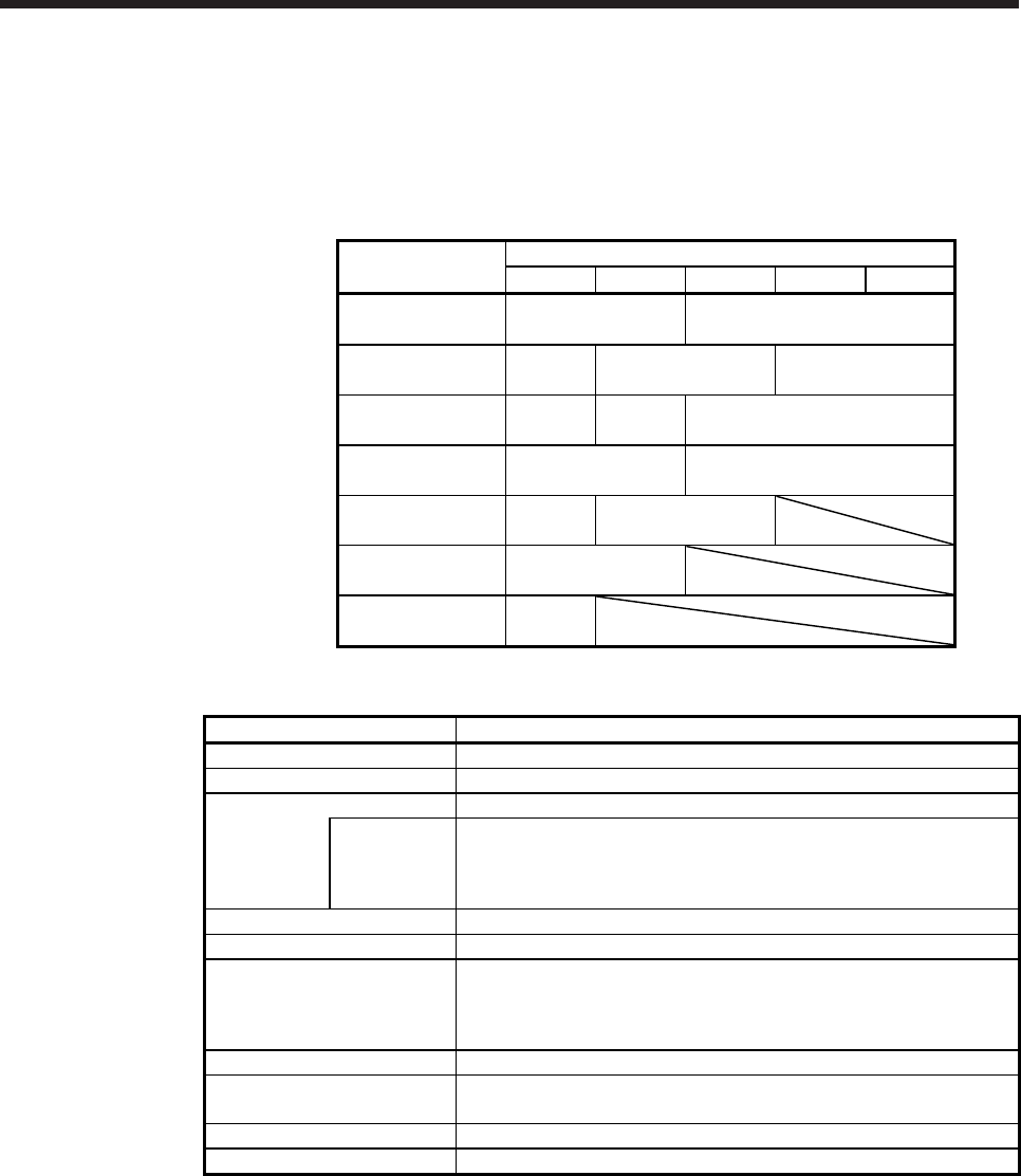
7. HG-SR SERIES
7 - 14
7.6.2 For high precision applications (G5/G7)
(1) Reduction ratio
The symbols (20A, 30A, 50A) in the following table indicate the model numbers of the reducers
assembled to the servo motors. Geared servo motors having the indicated reducer model numbers are
available. The reducer model number indicates _ _ _ of the reducer model HPG-_ _ _-05.
Servo motor Reduction ratio
1/5 1/11 1/21 1/33 1/45
HG-SR52(4)(B)G5 20A 32A
HG-SR52(4)(B)G7
HG-SR102(4)(B)G5 20A 32A 50A
HG-SR102(4)(B)G7
HG-SR152(4)(B)G5 20A 32A 50A
HG-SR152(4)(B)G7
HG-SR202(4)(B)G5 32A 50A
HG-SR202(4)(B)G7
HG-SR352(4)(B)G5 32A 50A
HG-SR352(4)(B)G7
HG-SR502(4)(B)G5 50A
HG-SR502(4)(B)G7
HG-SR702(4)(B)G5 50A
HG-SR702(4)(B)G7
(2) Specifications
Item Description
Mounting method Flange mounting
Mounting direction In any directions
Lubrication
method
Grease lubrication (already packed)
Packed with
Reducer model number 20A, 32A: Harmonic grease SK-2
(Harmonic Drive Systems)
Reducer model number 50A: Epiknock grease AP(N)2
(JX Nippon Oil & Energy)
Output shaft rotating direction Same as the servo motor output shaft direction.
Backlash (Note 3) 3 minutes or less at reducer output shaft
Permissible load to motor
inertia ratio (when converting
into the servo motor shaft)
(Note 1)
10 times or less
Maximum torque Three times of the servo motor rated torque
Maximum speed
(servo motor shaft) 3000 r/min (permissible instantaneous speed: 3450 r/min)
IP rating (reducer area) IP44 equivalent
Reducer efficiency (Note 2) 77% to 92%
Note 1. If the above indicated value is exceeded, please contact your local sales office.
2. The reducer efficiency differs depending on the reduction ratio. Also, it changes depending on the
operating conditions such as the output torque, speed and rotation, temperature, etc. The
numerical value in the table is a typical value in the rated torque, rated speed and rotation and
typical temperature, and not a guaranteed value.
3. The backlash can be converted: 1 min = 0.0167 °
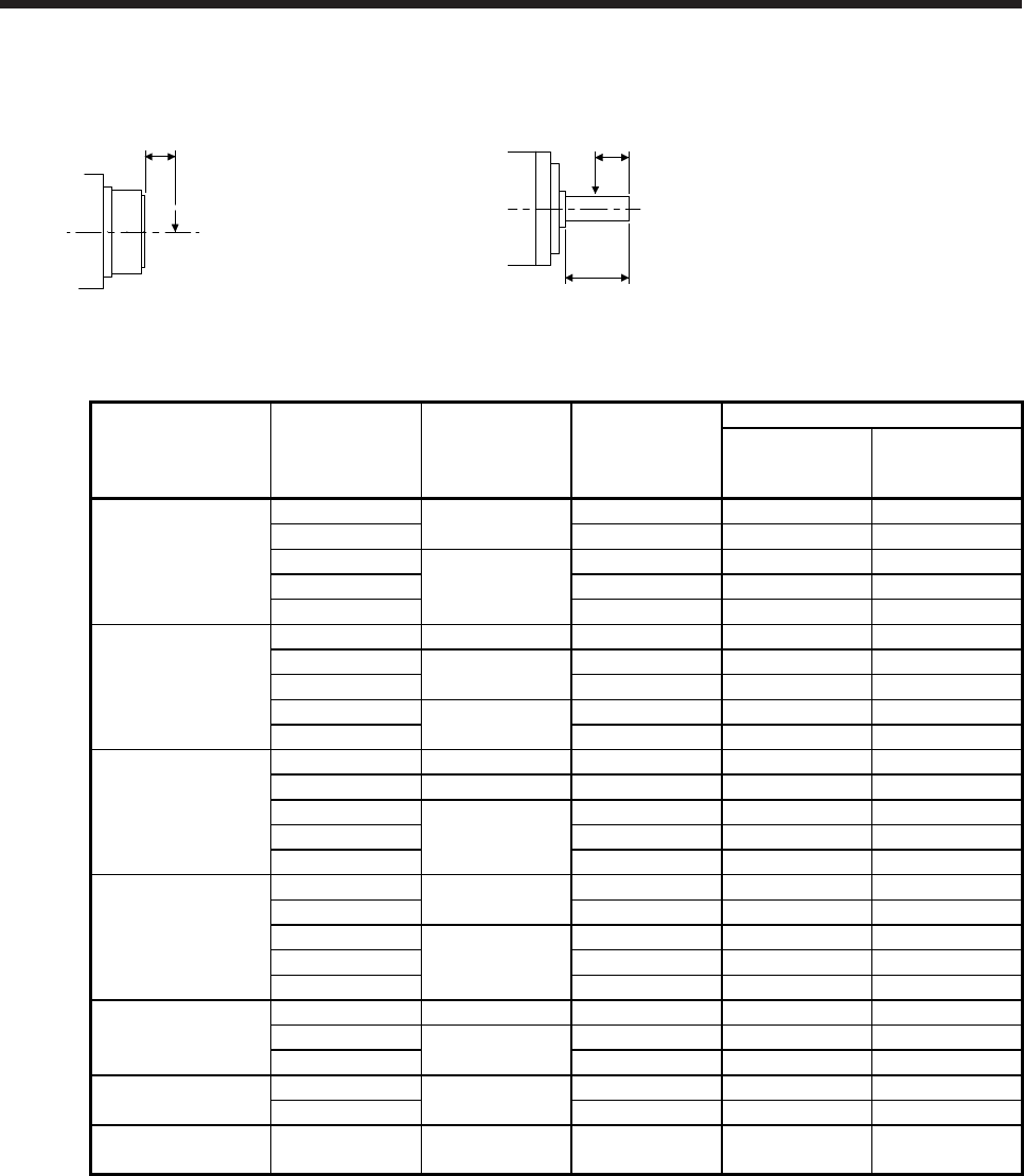
7. HG-SR SERIES
7 - 15
(3) Permissible loads of servo motor shaft
The radial load point of a high precision reducer is as shown below.
L: Distance between reducer
end face and load center
L
Q: Length of axis (Refer to section 7.7.9, 7.7.10.)
Q/2
Q
Flange-mounting flange output type for
high precision application (G5)
Flange-mounting shaft output type for
high precision application (G7)
Servo motor Reduction ratio Reducer model
number
Radial load point
L [mm]
Permissible load (Note)
Permissible radial
load
[N]
Permissible thrust
load
[N]
HG-SR52(4)(B)G5
HG-SR52(4)(B)G7
1/5 20A 32 416 1465
1/11 32 527 1856
1/21
32A
57 1094 4359
1/33 57 1252 4992
1/45 57 1374 5478
HG-SR102(4)(B)G5
HG-SR102(4)(B)G7
1/5 20A 32 416 1465
1/11 32A 57 901 3590
1/21 57 1094 4359
1/33 50A 62 2929 10130
1/45 62 3215 11117
HG-SR152(4)(B)G5
HG-SR152(4)(B)G7
1/5 20A 32 416 1465
1/11 32A 57 901 3590
1/21
50A
62 2558 8845
1/33 62 2929 10130
1/45 62 3215 11117
HG-SR202(4)(B)G5
HG-SR202(4)(B)G7
1/5 32A 57 711 2834
1/11 57 901 3590
1/21
50A
62 2558 8845
1/33 62 2929 10130
1/45 62 3215 11117
HG-SR352(4)(B)G5
HG-SR352(4)(B)G7
1/5 32A 57 711 2834
1/11 50A 62 2107 7285
1/21 62 2558 8845
HG-SR502(4)(B)G5
HG-SR502(4)(B)G7
1/5 50A 62 1663 5751
1/11 62 2107 7285
HG-SR702(4)(B)G5
HG-SR702(4)(B)G7 1/5 50A 62 1663 5751
Note. Do not subject the shaft to load greater than the value.
The value in the table assumes that the load is applied independently.
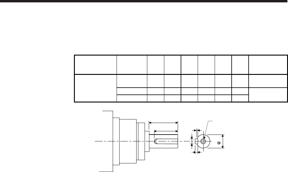
7. HG-SR SERIES
7 - 16
(4) Servo motor with special shaft
Servo motors with special shafts having keyway (with single pointed keys) are available for the flange-
mounting shaft output type for high precision applications (G7).
[Unit: mm]
Servo motor
Reducer
model
number
Q φS W T QK U Y
HG-SR_(4)(B)G7K
20A 42 25h7 8 7 36 4
M6 screw hole
depth 12
32A 82 40h7 12 8 70 5
M10 screw hole
depth 20
50A 82 50h7 14 9 70 5.5
U
W
T
Y
Q
QK
S
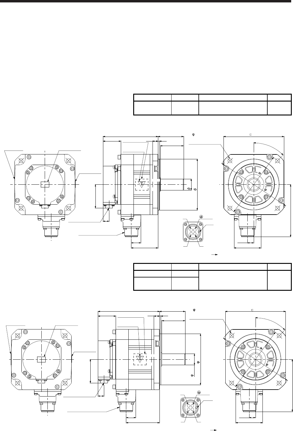
7. HG-SR SERIES
7 - 17
7.7 Dimensions
Moment of inertia on the table is the value calculated by converting the total value of moment of inertia for
servo motor, reducer, and electromagnetic brake with servo motor shaft.
The dimensions without tolerances are general tolerance.
The outer frame of the reducer is a material surface such as casting. Its actual dimensions may be 1 mm to
3 mm larger than the drawing dimensions. Design the machine-side with allowances.
7.7.1 Standard (without electromagnetic brake and reducer)
Model Output [kW] Moment of inertia J [× 10-4 kg•m2] Mass [kg]
HG-SR52
HG-SR524 0.5 7.26 4.8
[Unit: mm]
AB
CD
4- 9 mounting hole
Use hexagon socket
head cap screw.
45°
165
145
Motor plate Caution plate
Caution plate
Bottom
Top
Bottom
Top
Top
Bottom
12 3
50
55118.5
38.2
Caution plate
Motor plate
(Opposite side)
130
13.5
58
112.5
20.9
57.8
50.9
13
Encoder connector
CMV1-R10P
Power supply connector
MS3102A18-10P
Bottom
Top
U
W
V
Power supply connector
Motor flange direction
Key
BC41038A
24h6
110h7
(PE)
Model Output [kW] Moment of inertia J [× 10-4 kg•m2] Mass [kg]
HG-SR51 0.5
11.6 6.2
HG-SR102
HG-SR1024 1.0
[Unit: mm]
AB
CD
BC41045A BC41039A
24h6
110h7
4- 9 mounting hole
Use hexagon socket
head cap screw.
45°
145
165
Motor plate Caution plate
Caution plate
Bottom
Top
Bottom
Top Top
Bottom
12 3
50
55132.5
38.2
Caution plate
Motor plate
(Opposite side)
130
13.5
58
112.5
20.9
71.8
50.9
13
Encoder connector
CMV1-R10P
Power supply connector
MS3102A18-10P
Bottom
Top
U
W
V
Power supply connector
Motor flange direction
Key
(PE)
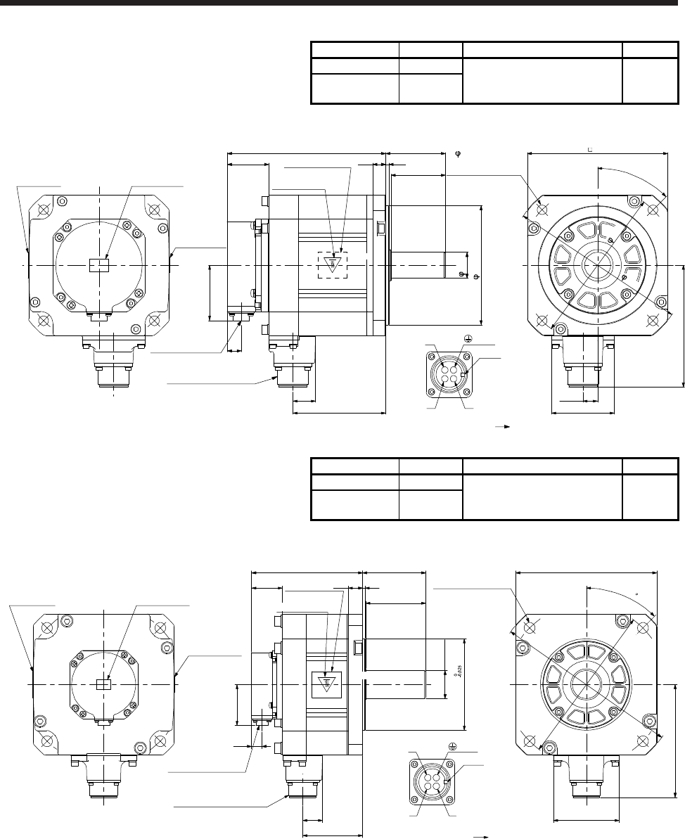
7. HG-SR SERIES
7 - 18
Model Output [kW] Moment of inertia J [× 10-4 kg•m2] Mass [kg]
HG-SR81 0.85
16.0 7.3
HG-SR152
HG-SR1524 1.5
[Unit: mm]
BC41046A BC41040A
4- 9 mounting hole
Use hexagon socket
head cap screw.
AB
CD
Motor plate Caution plate
Caution plate
Bottom
Top
Bottom
Top Top
Bottom
12 3
50
55146.5
38.2
Caution plate
Motor plate
(Opposite side)
130
13.5
58
112.5
20.9
85.8
50.9
13
Encoder connector
CMV1-R10P
Power supply connector
MS3102A18-10P
Bottom
Top
U
W
V
Power supply connector
Motor flange direction
Key
110h7
24h6
(PE)
45°
165
145
Model Output [kW] Moment of inertia J [× 10-4 kg•m2] Mass [kg]
HG-SR121 1.2
46.8 11
HG-SR202
HG-SR2024 2.0
[Unit: mm]
AB
CD
BC41047A BC41041A
4-φ13.5 mounting hole
Use hexagon socket
head cap screw.
φ114.3
(PE)
Motor plate Caution plate
Caution plate
Bottom
Top Top
Bottom
Top
18 3
75
79138.5
38.5
Caution plate
Motor plate
(Opposite side)
□176
82
140.9
24.8
74.8
50.9
13
Encoder connector
CMV1-R10P
Power supply connector
MS3102A22-22P U
W
V
Power supply connector
Motor flange direction
Key
Bottom
Top
45
φ230
φ200
φ35+0.010
0
Bottom
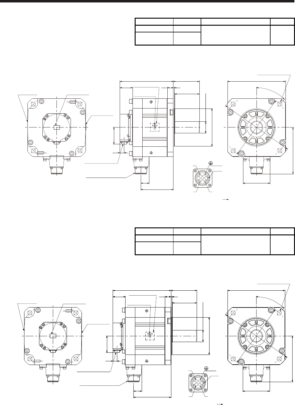
7. HG-SR SERIES
7 - 19
Model Output [kW] Moment of inertia J [× 10-4 kg•m2] Mass [kg]
HG-SR201 2.0
78.6 16
HG-SR352
HG-SR3524 3.5
[Unit: mm]
Motor plate Caution plate
Caution plate
Bottom
Top Top
Bottom
18 3
75
79162.5
38.5
Caution plate
Motor plate
(Opposite side)
□176
45°
82
140.9
φ114.3 0
-0.025
24.8
98.8
50.9
13
Encoder connector
CMV1-R10P
Power supply connector
MS3102A22-22P
4-φ13.5 mounting hole
Use hexagon socket
head cap screw.
Bottom
Top
U
W
V
Power supply connector
Motor flange direction
Key
Bottom
Top
(Note)
*1
(Note)
*2
φ200
φ230
(PE)
BC41048A BC41042A
+0.010
0
φ35
(Note)
*1
(Note)
*2
Note. *1 and *2 are screw hole for eyebolt (M8).
Model Output [kW] Moment of inertia J [× 10-4 kg•m2] Mass [kg]
HG-SR301 3.0
99.7 20
HG-SR502
HG-SR5024 5.0
[Unit: mm]
Motor plate Caution plate
Caution plate
Bottom
Top Top
Bottom
18 3
75
79178.5
38.5
Caution plate
Motor plate
(Opposite side)
□176
45°
82
140.9
φ114.3 0
-0.025
24.8
114.8
50.9
13
Encoder connector
CMV1-R10P
Power supply connector
MS3102A22-22P
4-φ13.5 mounting hole
Use hexagon socket
head cap screw.
Bottom
Top
U
W
V
Power supply connector
Motor flange direction
Key
Bottom
Top
(Note)
*1
(Note)
*2
φ200
φ230
(PE)
BC41049A BC41043A
+0.010
0
φ35
(Note)
*1
(Note)
*2
Note. *1 and *2 are screw hole for eyebolt (M8).
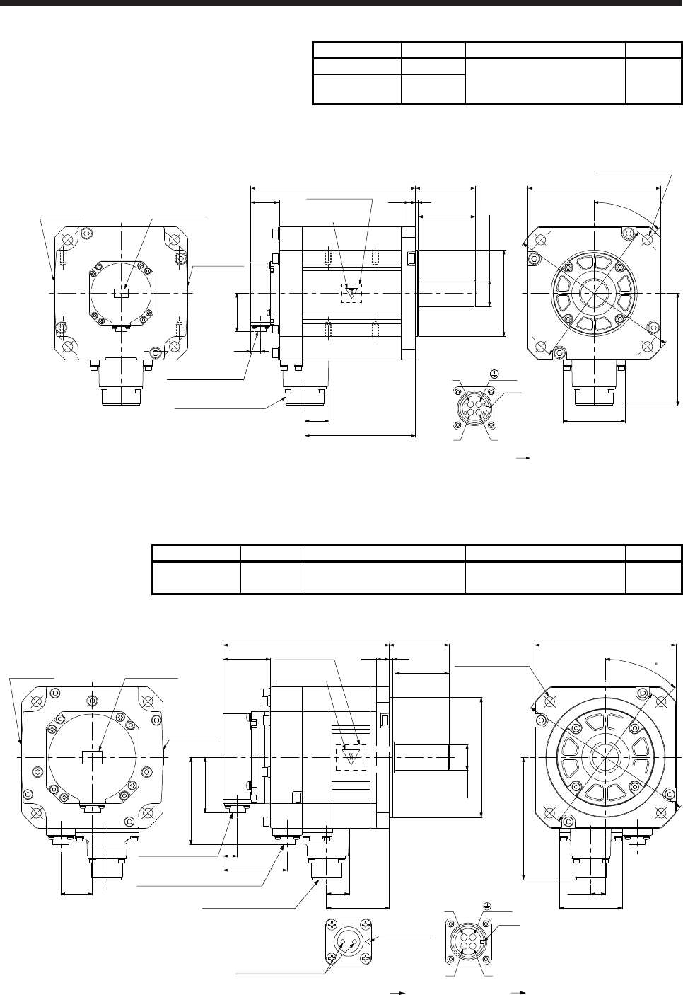
7. HG-SR SERIES
7 - 20
Model Output [kW] Moment of inertia J [× 10-4 kg•m2] Mass [kg]
HG-SR421 4.2
151 27
HG-SR702
HG-SR7024 7.0
[Unit: mm]
Motor plate Caution plate
Caution plate
Bottom
Top Top
Bottom
18 3
75
79218.5
38.5
Caution plate
Motor plate
(Opposite side)
□176
45°
82
149.1
φ114.3 0
-0.025
32
146.8
50.9
13
Encoder connector
CMV1-R10P
Power supply connector
MS3102A32-17P
4-φ13.5 mounting hole
Use hexagon socket
head cap screw.
Bottom
Top
U
W
V
Power supply connector
Motor flange direction
Key
Bottom
Top
φ200
φ230
(Note)
*1
(Note)
*4 (Note)
*2
(Note)
*3
(PE)
BC41050A BC41044A
+0.010
0
φ35
(Note)
*1
(Note)
*2 (Note)
*4
(Note)
*3
Note. *1, *2, *3, and *4 are screw hole for eyebolt (M8).
7.7.2 With an electromagnetic brake
Model Output [kW] Brake static friction torque [N•m] Moment of inertia J [× 10-4 kg•m2] Mass [kg]
HG-SR52B
HG-SR524B 0.5 8.5 9.48 6.7
[Unit: mm]
AB
CD
Motor plate Caution plate
Caution plate
Bottom
Top
Bottom
Top Top
Bottom
12 3
50
55153
43.5
Caution plate
Motor plate
(Opposite side)
□130
13.5
58
112.5
20.9
57.8
50.9
13
Encoder connector
CMV1-R10P
Power supply connector
MS3102A18-10P
Bottom
Top
U
W
V
Power supply connector
Motor flange direction
Key
Electromagnetic brake connector
CMV1-R2P
79.9
59
Electromagnetic brake
Electromagnetic brake connector
Motor flange direction
Main key
position mark
29
φ110h7
φ24h6
45
4-φ9 mounting hole
Use hexagon socket
head cap screw.
φ145
φ165
(PE)
BC41051*
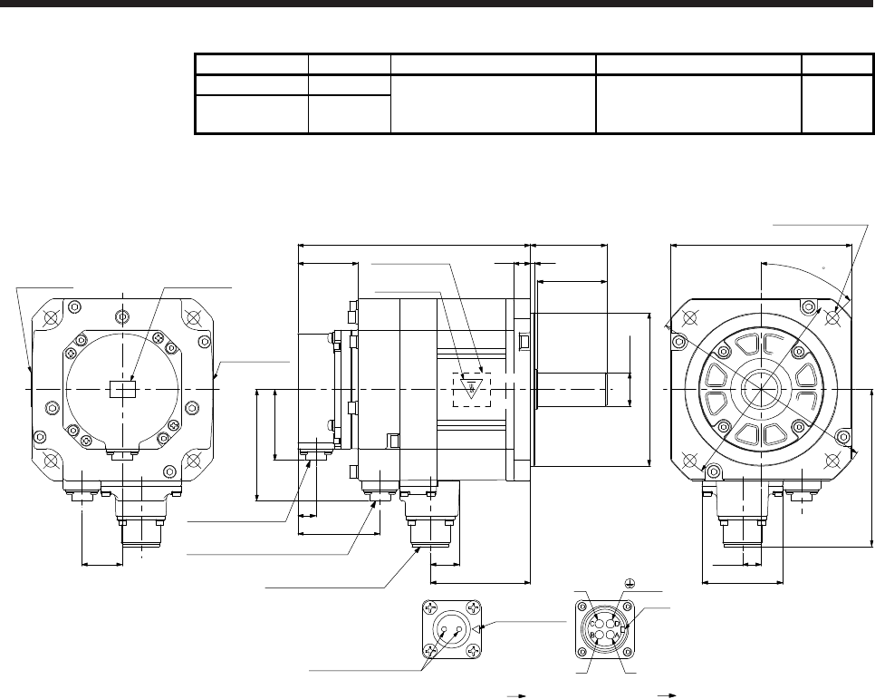
7. HG-SR SERIES
7 - 21
Model Output [kW] Brake static friction torque [N•m] Moment of inertia J [× 10-4 kg•m2] Mass [kg]
HG-SR51B 0.5
8.5 13.8 8.2
HG-SR102B
HG-SR1024B 1.0
[Unit: mm]
Motor plate Caution plate
Caution plate
Bottom
Top
Bottom
Top Top
Bottom
12 3
50
55167
43.5
Caution plate
Motor plate
(Opposite side)
□130
13.5
58
112.5
20.9
71.8
50.9
13
Encoder connector
CMV1-R10P
Power supply connector
MS3102A18-10P
Bottom
Top
U
W
Main key
position mark
V
Power supply connector
Motor flange direction
Key
Electromagnetic brake connector
CMV1-R2P
79.9
59
Electromagnetic brake
Electromagnetic brake connector
Motor flange direction
29
4-φ9 mounting hole
Use hexagon socket
head cap screw.
BC41058* BC41052*
φ145
φ165
45
(PE)
φ24h6
φ110h7
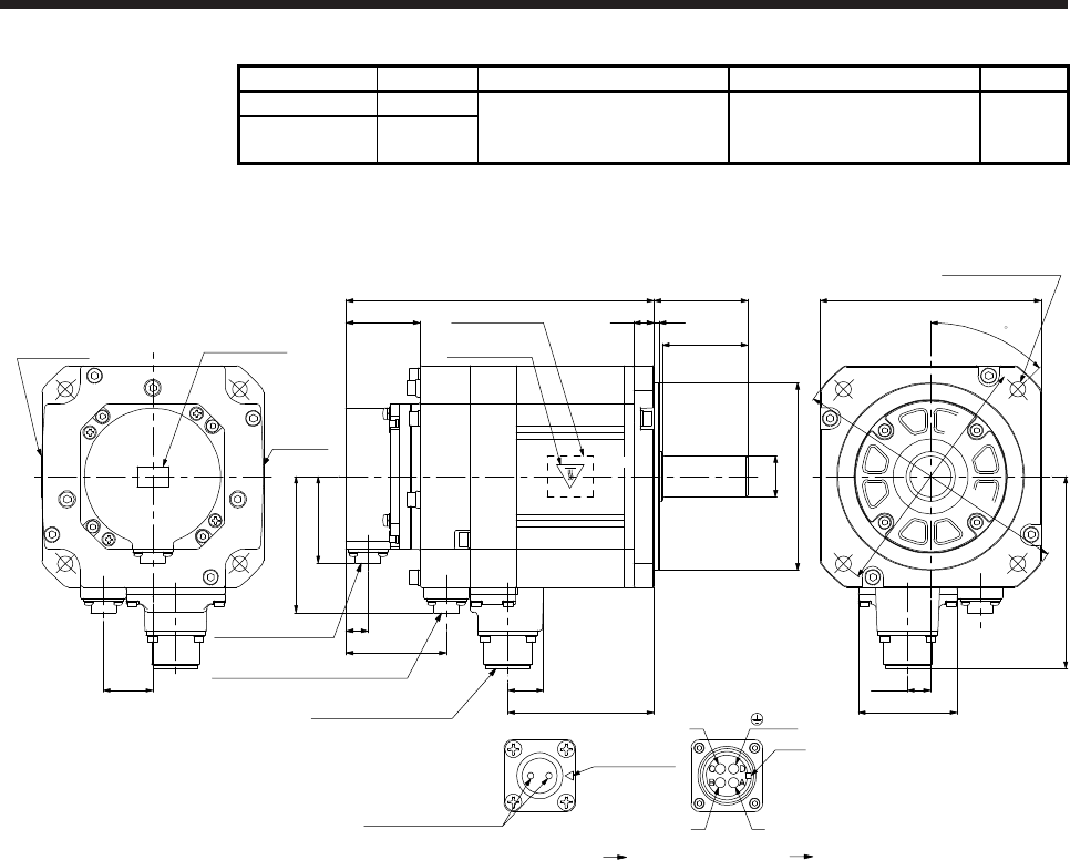
7. HG-SR SERIES
7 - 22
Model Output [kW] Brake static friction torque [N•m] Moment of inertia J [× 10-4 kg•m2] Mass [kg]
HG-SR81B 0.85
8.5 18.2 9.3
HG-SR152B
HG-SR1524B 1.5
[Unit: mm]
45
4-φ9 mounting hole
Use hexagon socket
head cap screw.
φ145
φ165
BC41059* BC41053*
(PE)
Motor plate Caution plate
Caution
plate
Bottom
Top
Bottom
Top Top
Bottom
12 3
50
55181
43.5
Caution plate
Motor plate
(Opposite side)
□130
13.5
58
112.5
20.9
85.8
50.9
13
Encoder connector
CMV1-R10P
Power supply connector
MS3102A18-10P
Bottom
Top
U
W
V
Power supply connector
Motor flange direction
Key
Electromagnetic brake connector
CMV1-R2P
79.9
59
Electromagnetic brake
Electromagnetic brake connector
Motor flange direction
Main key
position mark
29
φ24h6
φ110h7
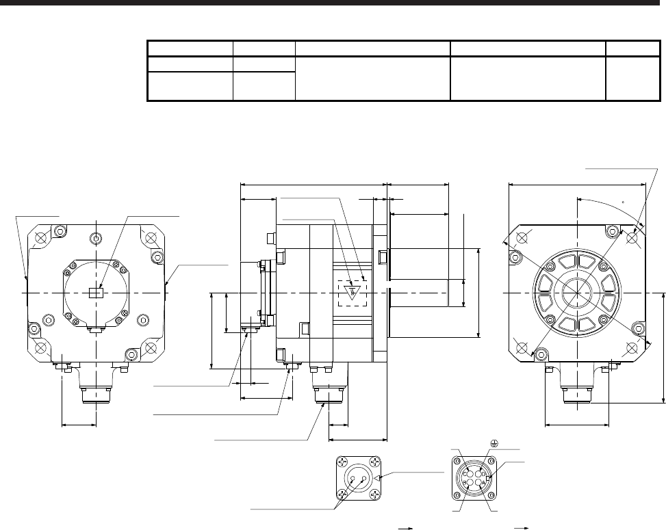
7. HG-SR SERIES
7 - 23
Model Output [kW] Brake static friction torque [N•m] Moment of inertia J [× 10-4 kg•m2] Mass [kg]
HG-SR121B 1.2
44 56.5 17
HG-SR202B
HG-SR2024B 2.0
[Unit: mm]
BC41060* BC41054*
Motor plate Caution plate
Caution plate
Bottom
Top Top
Bottom
18 3
75
79188
45.5
Caution plate
Motor plate
(Opposite side)
□176
82
140.9
24.8
74.8
Bottom
Top
Bottom
Top
50.9
13
Encoder connector
CMV1-R10P
Power supply connector
MS3102A22-22P
96.9
Electromagnetic brake connector
CMV1-R2P
66.5
U
W
V
Power supply connector
Motor flange direction
Key
Electromagnetic brake
Electromagnetic brake connector
Motor flange direction
Main key
position mark
44
(PE)
φ200
φ230
45
4-φ13.5 mounting hole
Use hexagon socket
head cap screw.
+0.010
0
φ35
φ114.3 0
-0.025
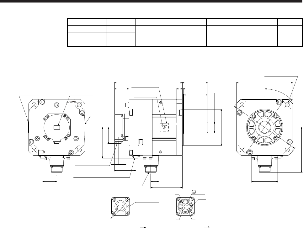
7. HG-SR SERIES
7 - 24
Model Output [kW] Brake static friction torque [N•m] Moment of inertia J [× 10-4 kg•m2] Mass [kg]
HG-SR201B 2.0
44 88.2 22
HG-SR352B
HG-SR3524B 3.5
[Unit: mm]
Motor plate Caution plate
Caution plate
Bottom
Top Top
Bottom
18 3
75
79212
45.5
Caution plate
Motor plate
(Opposite side)
□176
45°
82
140.9
φ114.3 0
-0.025
24.8
98.8
4-φ13.5 mounting hole
Use hexagon socket
head cap screw.
Bottom
Top
Bottom
Top
(Note)
*1
(Note)
*2
φ200
φ230
50.9
13
Encoder connector
CMV1-R10P
Power supply connector
MS3102A22-22P
96.9
Electromagnetic brake connector
CMV1-R2P
66.5
U
W
V
Power supply connector
Motor flange direction
Key
Electromagnetic brake
Electromagnetic brake connector
Motor flange direction
Main key
position mark
44
BC41061* BC41055*
(PE)
+0.010
0
φ35
(Note)
*1
(Note)
*2
Note. *1 and *2 are screw hole for eyebolt (M8).
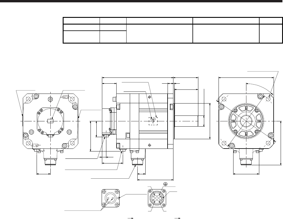
7. HG-SR SERIES
7 - 25
Model Output [kW] Brake static friction torque [N•m] Moment of inertia J [× 10-4 kg•m2] Mass [kg]
HG-SR301B 3.0
44 109 26
HG-SR502B
HG-SR5024B 5.0
[Unit: mm]
Motor plate Caution plate
Caution plate
Bottom
Top Top
Bottom
18 3
75
79228
45.5
Caution plate
Motor plate
(Opposite side)
□176
45°
82
140.9
φ114.3 0
-0.025
24.8
114.8
4-φ13.5 mounting hole
Use hexagon socket
head cap screw.
Bottom
Top
Bottom
Top
(Note)
*1
(Note)
*2
φ200
φ230
50.9
13
Encoder connector
CMV1-R10P
Power supply connector
MS3102A22-22P
96.9
Electromagnetic brake connector
CMV1-R2P
66.5
U
W
V
Power supply connector
Motor flange direction
Key
Electromagnetic brake
Electromagnetic brake connector
Motor flange direction
Main key
position mark
44
BC41062* BC41056*
(PE)
+0.010
0
φ35
(Note)
*1
(Note)
*2
Note. *1 and *2 are screw hole for eyebolt (M8).
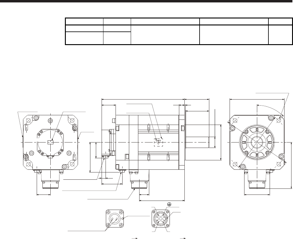
7. HG-SR SERIES
7 - 26
Model Output [kW] Brake static friction torque [N•m] Moment of inertia J [× 10-4 kg•m2] Mass [kg]
HG-SR421B 4.2
44 161 33
HG-SR702B
HG-SR7024B 7.0
[Unit: mm]
Motor plate Caution plate
Caution
plate
Bottom
Top Top
Bottom
18 3
75
79268
45.5
Caution plate
Motor plate
(Opposite side)
□176
45°
82
149.1
φ114.3 0
-0.025
32
146.8
50.9
13
Encoder connector
CMV1-R10P
Power supply connector
MS3102A32-17P
4-φ13.5 mounting hole
Use hexagon socket
head cap screw.
Bottom
Top
U
W
V
Power supply connector
Motor flange direction
Key
Top
φ200
φ230
Electromagnetic brake
Electromagnetic brake connector
Motor flange direction
Main key
position mark
96.9
Electromagnetic brake connector
CMV1-R2P
66.5
44
(Note)
*2
(Note)
*4
(Note)
*1 (Note)
*3
BC41063* BC41057*
(PE)
+0.010
0
φ35
Bottom
(Note)
*1
(Note)
*2
(Note)
*4
(Note)
*3
Note. *1, *2, *3, and *4 are screw hole for eyebolt (M8).
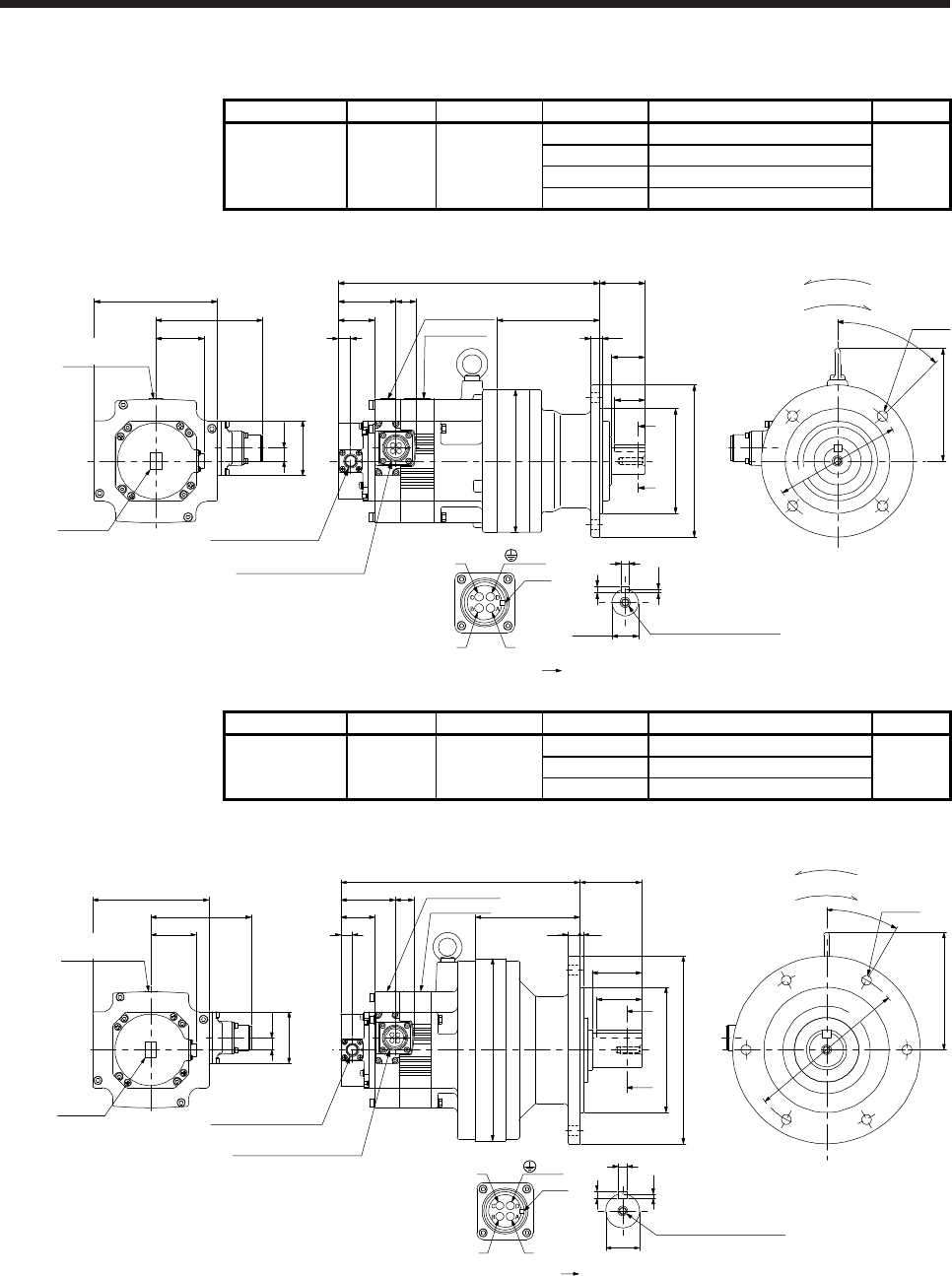
7. HG-SR SERIES
7 - 27
7.7.3 For general industrial machine with a reducer (without an electromagnetic brake)
Model Output [kW] Reducer model Reduction ratio Moment of inertia J [× 10-4 kg•m2] Mass [kg]
HG-SR52G1
HG-SR524G1 0.5
1/6 8.08
18
CNVM-6100 1/11 7.65
1/17 7.53
1/29 7.47
[Unit: mm]
For reverse rotation command
For forward rotation command
Rotation direction
Caution plate
Motor plate
60.7
58
13.5
□130
112.5
50.9
Caution
plate
Motor plate
275
20.9
Bottom Top
Top
Bottom
U
W
V
Power supply connector
Motor flange direction
Key
Caution plate
(Side view of motor only)
13
Encoder connector
CMV1-R10P
Power supply connector
MS3102A18-10P
38.2
48
108
35
32
φ110f8
φ160
φ150
A
A
93
119
φ134
4-φ11
45°
Shaft section view AA
φ28h6
4
7
8
M8 Screw hole depth 20
(PE)
BC41117*
Model Output [kW] Reducer model Reduction ratio Moment of inertia J [× 10-4 kg•m2] Mass [kg]
HG-SR52G1
HG-SR524G1 0.5
1/35 8.26
27
CNVM-6120 1/43 8.22
1/59 8.18
[Unit: mm]
Shaft section view AA
φ38h6
8
5
10
M8 Screw hole depth 20
Caution plate
Motor plate
60.7
58
13.5
□130
112.5
50.9
Caution
plate
Motor plate
267.5
20.9
Bottom Top
Top
Bottom
U
W
V
Power supply connector
Motor flange direction
Key
Caution plate
(Side view of motor only)
13
38.2
φ204
φ180
55
117
69
φ210
φ140f8
30°
132
6-φ11
50 A
A
13 4
Encoder connector
CMV1-R10P
Power supply connector
MS3102A18-10P (PE)
BC41118*
For reverse rotation command
For forward rotation command
Rotation direction
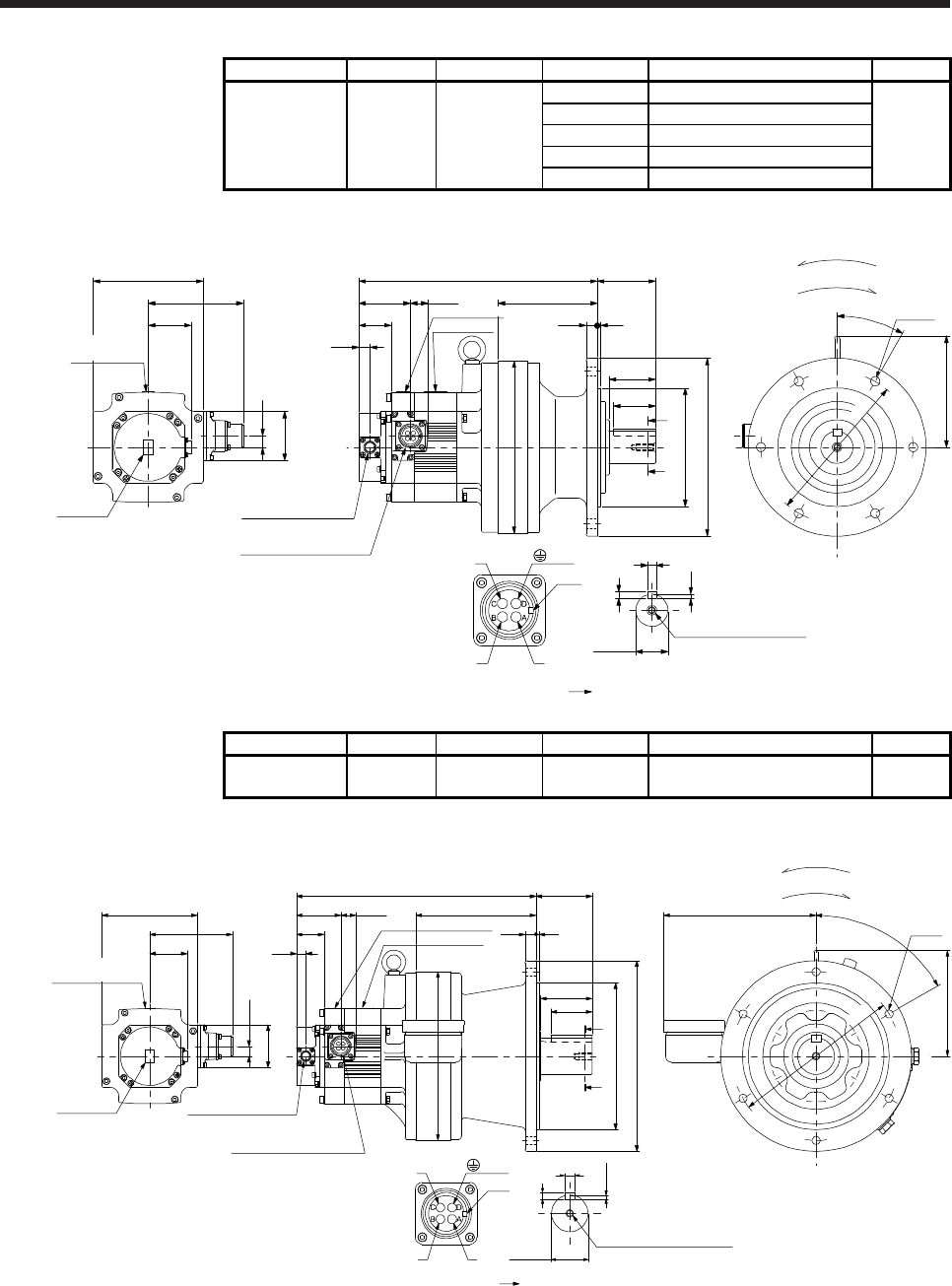
7. HG-SR SERIES
7 - 28
Model Output [kW] Reducer model Reduction ratio Moment of inertia J [× 10-4 kg•m2] Mass [kg]
HG-SR102G1
HG-SR1024G1 1.0
1/6 14.8
30
1/11 13.3
CNVM-6120 1/17 12.9
1/29 12.6
1/35 12.6
[Unit: mm]
(PE)
BC41119*
Caution plate
Motor plate
38.2
13
58
13.5
□130
112.5
50.9
Caution
plate
281.5
Bottom Top
Top
Bottom
U
W
V
Power supply connector
Motor flange direction
Key
(Side view of motor only)
Motor plate
Caution plate
20.960.7
Encoder connector
CMV1-R10P
Power supply connector
MS3102A18-10P
5
8
10
φ38h6
Shaft section view AA
M8 Screw hole depth 20
φ180
6-φ11
69
117
55
φ140f8
φ210
50
φ204
A
A
132
30°
13 4
For reverse rotation command
For forward rotation command
Rotation direction
Model Output [kW] Reducer model Reduction ratio Moment of inertia J [× 10-4 kg•m2] Mass [kg]
HG-SR102G1
HG-SR1024G1 1.0 CHVM-6130 1/43 13.8 49
[Unit: mm]
For reverse rotation command
For forward rotation command
Rotation direction
Caution plate
Motor plate
38.2
13
58
13.5
□130
112.5
50.9
Caution
plate
327
Bottom Top
Top
Bottom
U
W
V
Power supply connector
Motor flange direction
Key
(Side view of motor only)
Motor plate
Caution plate
20.960.7
Encoder connector
CMV1-R10P
Power supply connector
MS3102A18-10P
φ50h6
5.5
9
14
Shaft section view AA
M10 Screw hole depth 18
φ230
76
164
φ200f8
φ260
15 4
φ230
145
60°
208
6-φ11
56
A
A
70
(PE)
BC41120*
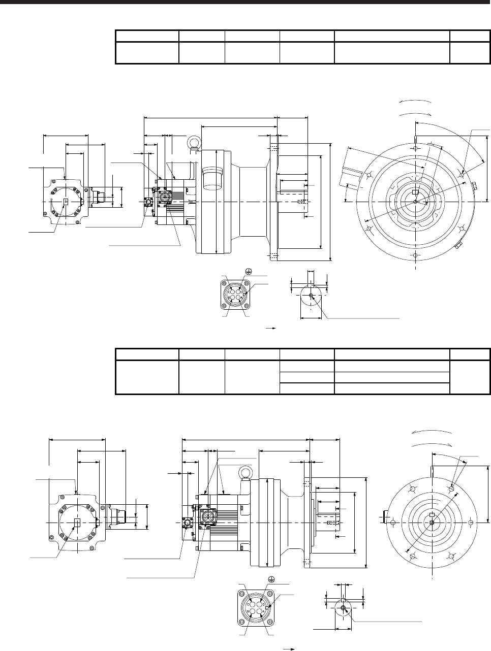
7. HG-SR SERIES
7 - 29
Model Output [kW] Reducer model Reduction ratio Moment of inertia J [× 10-4 kg•m2] Mass [kg]
HG-SR102G1
HG-SR1024G1 1.0 CHVM-6160 1/59 19.1 81
[Unit: mm]
Bottom
(PE)
BC41121*
Caution plate
Motor plate
38.2
13
58
13.5
□130
112.5
50.9
Caution
plate
384.5
Top
Top
Bottom
U
W
V
Power supply connector
Motor flange direction
Key
(Side view of motor only)
Motor plate
20.960.7
Encoder connector
CMV1-R10P
Power supply connector
MS3102A18-10P
7
M10 Screw hole depth 18
φ60h6
11
18
Shaft section view AA
6-φ11
192
φ300
219
89
φ270f8
φ340
φ310
60°
20 4
228
15°
175
90
A
A
80
Caution
plate
For reverse rotation command
For forward rotation command
Rotation direction
Model Output [kW] Reducer model Reduction ratio Moment of inertia J [× 10-4 kg•m2] Mass [kg]
HG-SR152G1
HG-SR1524G1 1.5
1/6 19.2
31
CNVM-6120 1/11 17.7
1/17 17.3
[Unit: mm]
Caution plate
Motor plate
38.2
13
58
13.5
□130
112.5
50.9
Caution
plate
295.5
Bottom Top
TopBottom
U
W
V
Power supply connector
Motor flange direction
Key
(Side view of motor only)
Motor plate
Caution plate
20.960.7
Encoder connector
CMV1-R10P
Power supply connector
MS3102A18-10P
5
8
10
φ38h6
Shaft section view AA
M8 Screw hole depth 20
φ180
6-φ11
69
117
55
φ140f8
φ210
50
φ204
A
132
30°
13 4
A
(PE)
BC41122*
For reverse rotation command
For forward rotation command
Rotation direction
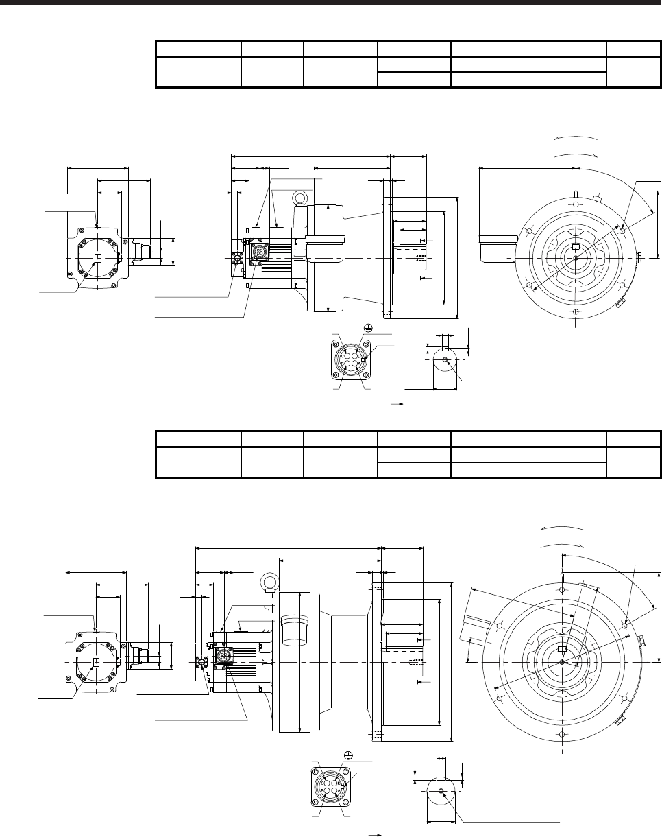
7. HG-SR SERIES
7 - 30
Model Output [kW] Reducer model Reduction ratio Moment of inertia J [× 10-4 kg•m2] Mass [kg]
HG-SR152G1
HG-SR1524G1 1.5 CHVM-6130 1/29 18.4
50
1/35 18.3
[Unit: mm]
Caution plate
Motor plate
38.2
13
58
13.5
□130
112.5
50.9
Caution
plate
341
Top
TopBottom
U
W
V
Power supply connector
Motor flange direction
Key
(Side view of motor only)
Motor plate
Caution plate
20.960.7
Encoder connector
CMV1-R10P
Power supply connector
MS3102A18-10P
φ50h6
5.5
9
14
Shaft section view AA
M10 Screw hole depth 18
φ230
76
164
φ200f8
φ260
15 4
φ230
145
60°
208
6-φ11
56
A
A
70
(PE)
BC41123*
Bottom
For reverse rotation command
For forward rotation command
Rotation direction
Model Output [kW] Reducer model Reduction ratio Moment of inertia J [× 10-4 kg•m2] Mass [kg]
HG-SR152G1
HG-SR1524G1 1.5 CHVM-6160 1/43 23.6
82
1/59 23.5
[Unit: mm]
Bottom
Caution plate
Motor plate
38.2
13
58
13.5
□130
112.5
50.9
Caution
plate
398.5
Top
Top
Bottom
U
W
V
Power supply connector
Motor flange direction
Key
(Side view of motor only)
Motor plate
20.960.7
Encoder connector
CMV1-R10P
Power supply connector
MS3102A18-10P
7
M10 Screw hole depth 18
φ60h6
11
18
Shaft section view AA
6-φ11
192
φ300
219
89
φ270f8
φ340
φ310
60°
20 4
228
15°
175
90
A
80
A
(PE)
BC41124*
For reverse rotation command
For forward rotation command
Rotation direction
Caution plate
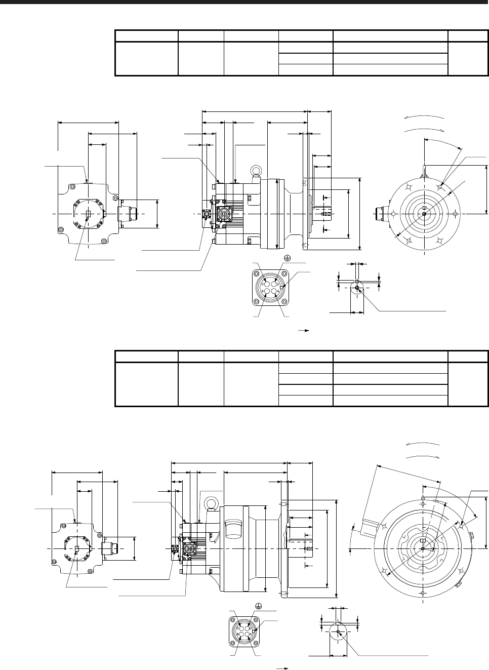
7. HG-SR SERIES
7 - 31
Model Output [kW] Reducer model Reduction ratio Moment of inertia J [× 10-4 kg•m2] Mass [kg]
HG-SR202G1
HG-SR2024G1 2.0
1/6 50.0
36
CNVM-6120 1/11 48.4
1/17 48.1
[Unit: mm]
U
W
V
Power supply connector
Motor flange direction
Key
Shaft section view AA
5
10
8
φ38h6 M8 Screw hole depth 20
φ204
6-φ11
φ180
142
30°
A
A
117
4
69
55
50
φ140f8
φ210
(Side view of motor only)
□176
140.9
Top
50.9
Top
82
Caution plate
Power supply connector
MS3102A22-22P
Encoder connector
CMV1-R10P
13
24.863.7
38.5
Motor plate
305.5
13
Caution plate (PE)
BC41125*
Caution plate
Motor plate
Bottom
Bottom
For reverse rotation command
For forward rotation command
Rotation direction
Model Output [kW] Reducer model Reduction ratio Moment of inertia J [× 10-4 kg•m2] Mass [kg]
HG-SR202G1
HG-SR2024G1 2.0
1/29 54.8
87
CHVM-6165 1/35 54.5
1/43 54.3
1/59 54.2
[Unit: mm]
For reverse rotation command
For forward rotation command
Rotation direction
U
W
V
Power supply connector
Motor flange direction
Key
M10 Screw hole depth 18
Shaft section view AA
18
11
7
φ60h6
6-φ11
A
A
219
4
89402.5
20
φ300
80
90
φ270f8
φ340
181
60°
15°
228
175
φ310
(Side view of motor only)
□176
140.9
Caution plate
Motor plate
Top
50.9
Top
Bottom
82
Caution plate
Power supply connector
MS3102A22-22P
Encoder connector
CMV1-R10P
13
24.863.7
38.5 Motor
plate
Caution plate
(PE)
BC41126*
Bottom
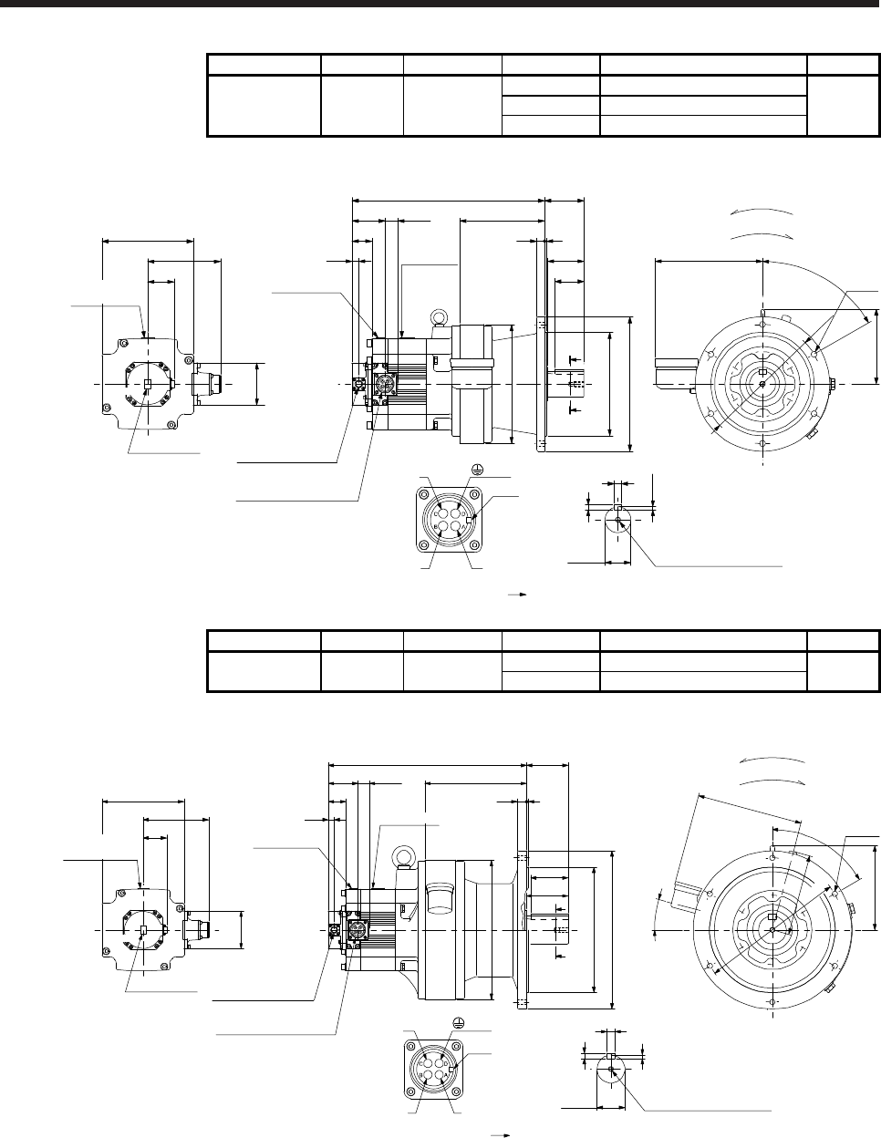
7. HG-SR SERIES
7 - 32
Model Output [kW] Reducer model Reduction ratio Moment of inertia J [× 10-4 kg•m2] Mass [kg]
HG-SR352G1
HG-SR3524G1 3.5
1/6 87.1
60
CHVM-6135 1/11 82.8
1/17 81.5
[Unit: mm]
U
W
V
Power supply connector
Motor flange direction
Key
13
24.8
63.7
38.5
Shaft section view AA
φ50h6 M10 Screw hole depth 18
14
9
5.5
A
A
6-φ11
4
15
76372
164
56
70
φ200f8
φ260
145
208
60°
φ230
φ230
(Side view of motor only)
□176
140.9
Caution plate
Caution plate
Motor plate
Top
50.9
Top
82
Power supply connector
MS3102A22-22P
Encoder connector
CMV1-R10P
Motor plate
Caution plate
(PE)
BC41127*
For reverse rotation command
For forward rotation command
Rotation direction
Bottom
Bottom
Model Output [kW] Reducer model Reduction ratio Moment of inertia J [× 10-4 kg•m2] Mass [kg]
HG-SR352G1
HG-SR3524G1 3.5 CHVM-6165 1/29 86.6
92
1/35 86.3
[Unit: mm]
U
W
Key
V
Power supply connector
Motor flange direction
13
24.863.7
38.5
M10 Screw hole depth 18
Shaft section view AA
18
11
7
φ60h6
6-φ11
A
A
219
4
89426.5
20
φ300
80
90
φ270f8
φ340
181
60°
15°
228
175
φ310
(Side view of motor only)
□176
140.9
Caution plate
Caution plate
Motor plate
Top
50.9
Top
82
Power supply connector
MS3102A22-22P
Encoder connector
CMV1-R10P
Motor plate
Caution plate
(PE)
BC41128*
Bottom
Bottom
For reverse rotation command
For forward rotation command
Rotation direction
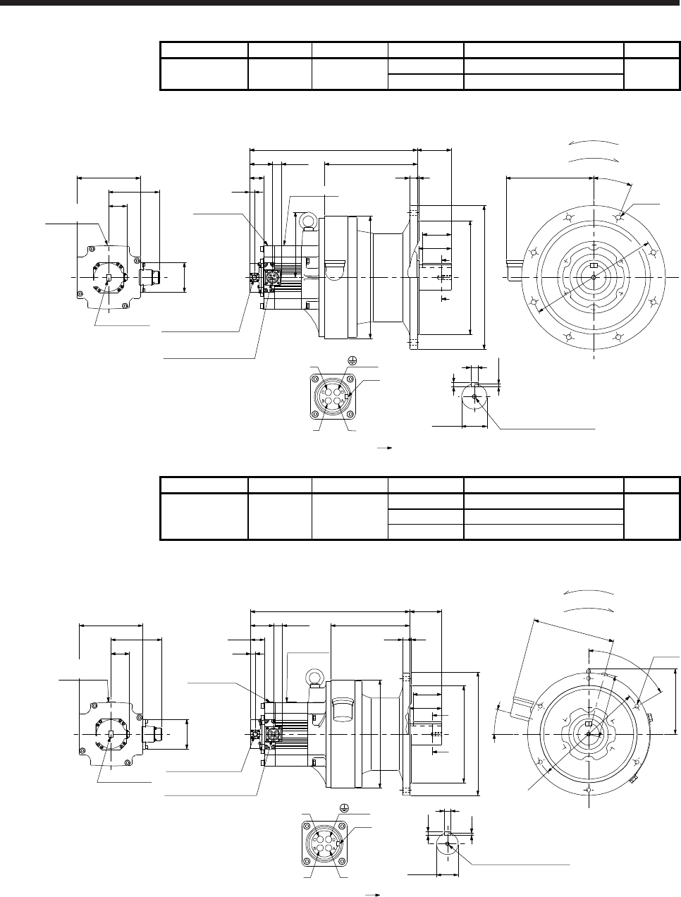
7. HG-SR SERIES
7 - 33
Model Output [kW] Reducer model Reduction ratio Moment of inertia J [× 10-4 kg•m2] Mass [kg]
HG-SR352G1
HG-SR3524G1 3.5 CHVM-6175 1/43 105
134
1/59 104
[Unit: mm]
Bottom
Bottom
U
W
V
Power supply connector
Motor flange direction
Key
M12 Screw hole depth24
13
24.863.7
Shaft section viewAA
38.5
20
12
7.5
φ70h6
φ316f8
8-φ14
A
A
80
90
258
5
22
94466
φ400
243
22.5°
φ360
φ340
181
□176
140.9
Caution plate
Caution plate
Motor plate
Top
50.9
Top
82
(Side view of motor only)
Caution plate
Power supply connector
MS3102A22-22P
Encoder connector
CMV1-R10P
Motor plate
(PE)
BC41129*
For reverse rotation command
For forward rotation command
Rotation direction
Model Output [kW] Reducer model Reduction ratio Moment of inertia J [× 10-4 kg•m2] Mass [kg]
HG-SR502G1
HG-SR5024G1 5.0
1/6 126
96
CHVM-6165 1/11 114
1/17 110
[Unit: mm]
U
W
V
Power supply connector
Motor flange direction
Key
□176
140.9
Caution plate
82
Caution plate
Motor plate
Motor plate
Caution plate
13
24.863.7
Top
50.9
38.5
Top
A
φ300
219
20 4
80
90
φ340
φ270f8
89
A
φ310
60°
181
15°
228
175
6-φ11
442.5
18
7
11
Shaft section view AA
φ60h6
M10 Screw hole depth 18
(Side view of motor only)
Encoder connector
CMV1-R10P
Power supply connector
MS3102A22-22P (PE)
BC41130*
Bottom
Bottom
For reverse rotation command
For forward rotation command
Rotation direction
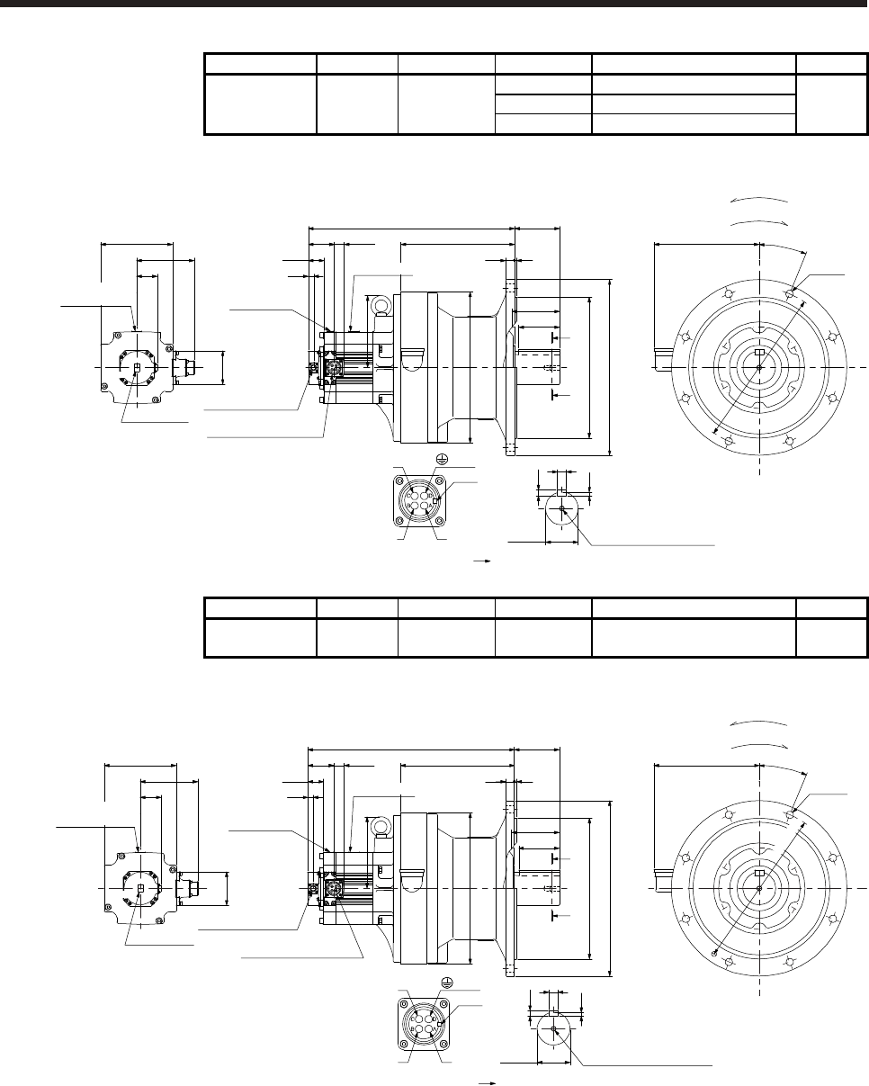
7. HG-SR SERIES
7 - 34
Model Output [kW] Reducer model Reduction ratio Moment of inertia J [× 10-4 kg•m2] Mass [kg]
HG-SR502G1
HG-SR5024G1 5.0
1/29 141
165
CHVM-6180 1/35 140
1/43 139
[Unit: mm]
Bottom
Bottom
U
W
V
Power supply connector
Motor flange direction
Key
176
M12 Screw hole depth 24
φ345f8
φ430
22 5
506 110
100
258
8-φ18
279
φ370
Motor plate
Caution plate
13
24.8
63.7
A
A
Shaft section view AA
110
38.5
22
14
9
φ80h6
22.5°
φ390
(Side view of motor only)
□176
140.9
Caution plate
82
Caution plate
Motor plate
Top
50.9
Top
Encoder connector
CMV1-R10P
Power supply connector
MS3102A22-22P
(PE)
BC41131*
For reverse rotation command
For forward rotation command
Rotation direction
Model Output [kW] Reducer model Reduction ratio Moment of inertia J [× 10-4 kg•m2] Mass [kg]
HG-SR502G1
HG-SR5024G1 5.0 CHVM-6185 1/59 138 165
[Unit: mm]
Bottom
Bottom
U
W
V
Power supply connector
Motor flange direction
Key
176
M12 Screw hole depth 24
φ345f8
φ430
22 5
506 110
100
258
8-φ18
279
φ370
Motor plate
Caution plate
13
24.863.7
A
A
Shaft section view AA
110
38.5
22
14
9
φ80h6
22.5°
(Side view of motor only)
□176
140.9
Caution plate
82
Caution plate
Motor plate
Top
50.9
Top
Encoder connector
CMV1-R10P
Power supply connector
MS3102A22-22P
(PE)
BC41132*
For reverse rotation command
For forward rotation command
Rotation direction
φ390
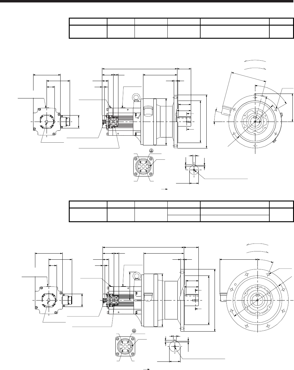
7. HG-SR SERIES
7 - 35
Model Output [kW] Reducer model Reduction ratio Moment of inertia J [× 10-4 kg•m2] Mass [kg]
HG-SR702G1
HG-SR7024G1 7.0 CHVM-6165 1/6 177 103
[Unit: mm]
Bottom
Bottom
(PE)
BC41133*
U
W
V
Power supply connector
Motor flange direction
Key
482.5
□176
149.1
Caution plate
82
Caution plate
Motor plate
Motor plate
Caution plate
13
3271.7
Top
50.9
38.5
Top
Shaft section view AA
φ310
60°
181
15°
228
175
6-φ11
18
7
11
φ60h6
M10 Screw hole depth 18
A
φ300
219
20 4
80
90
φ340
φ270f8
89
A
(Side view of motor only)
Encoder connector
CMV1-R10P
Power supply connector
MS3102A32-17P
For reverse rotation command
For forward rotation command
Rotation direction
Model Output [kW] Reducer model Reduction ratio Moment of inertia J [× 10-4 kg•m2] Mass [kg]
HG-SR702G1
HG-SR7024G1 7.0 CHVM-6170 1/11 190
145
1/17 182
[Unit: mm]
Bottom
Bottom
U
W
V
Power supply connector
Motor flange direction
Key
522
Motor plate
Caution plate
13
32
71.7
38.5
φ360
8-φ14
243
22.5°
7.5
20
12
M12 Screw hole depth 24
φ70h6
Shaft section view AA
90
φ400
φ316f8
80
φ340
A
94
258
522
A
181
(Side view of motor only)
□176
149.1
Caution plate
82
Caution plate
Motor plate
Top
50.9
Top
Encoder connector
CMV1-R10P
Power supply connector
MS3102A32-17P (PE)
BC41134*
For reverse rotation command
For forward rotation command
Rotation direction
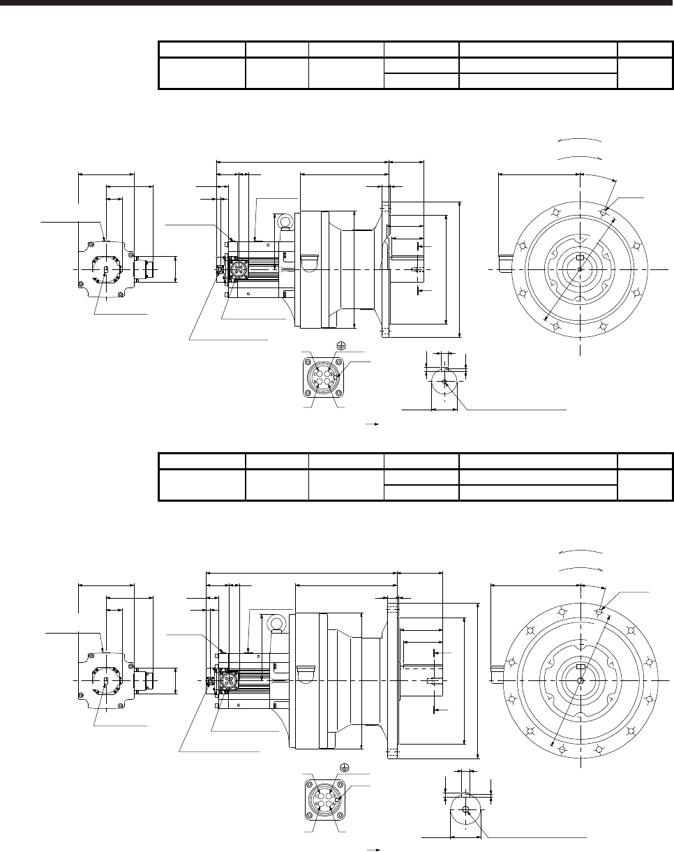
7. HG-SR SERIES
7 - 36
Model Output [kW] Reducer model Reduction ratio Moment of inertia J [× 10-4 kg•m2] Mass [kg]
HG-SR702G1
HG-SR7024G1 7.0 CHVM-6180 1/29 192
172
1/35 192
[Unit: mm]
Bottom
Bottom
U
W
V
Power supply connector
Motor flange direction
Key
546
Motor plate
Caution plate
13
32
71.7
Power supply
connector
MS3102A32-17P
38.5
176
φ345f8
φ430
22 5
110
100
279
φ370
A
A
110
258
8-φ18
22.5°
M12 Screw hole depth 24
Shaft section view AA
22
14
9
φ80h6
(Side view of motor only)
□176
149.1
Caution plate
82
Caution plate
Motor plate
Top
50.9
Top
Encoder connector
CMV1-R10P (PE)
BC41135*
For reverse rotation command
For forward rotation command
Rotation direction
φ390
Model Output [kW] Reducer model Reduction ratio Moment of inertia J [× 10-4 kg•m2] Mass [kg]
HG-SR702G1
HG-SR7024G1 7.0 CHVM-6195 1/43 267
240
1/59 266
[Unit: mm]
U
W
V
Power supply connector
Motor flange direction
Key
210
9
14
25
φ95h6 M20 Screw hole depth 34
φ400f8
φ490
30 6
602 145
125
285
15°
12-φ18
320
φ430
Motor plate
Caution
plate
13
32
71.7
Power supply
connector
MS3102A32-17P
A
A
Shaft section view AA
135
38.5
(Side view of motor only)
□176
149.1
Caution plate
82
Caution plate
Motor plate
Top
50.9
Top
Encoder connector
CMV1-R10P
(PE)
BC41136*
For reverse rotation command
For forward rotation command
Rotation direction
Bottom
Bottom
φ450
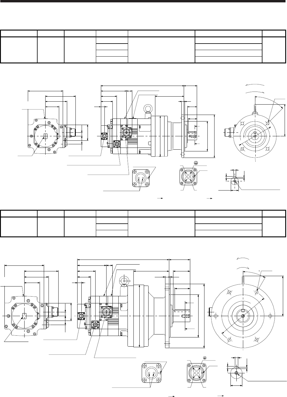
7. HG-SR SERIES
7 - 37
7.7.4 For general industrial machine with a reducer (with an electromagnetic brake)
Model Output [kW] Reducer model Reduction ratio Brake static friction torque [N•m] Moment of inertia J [× 10-4 kg•m2] Mass [kg]
HG-SR52BG1
HG-SR524BG1 0.5
1/6
8.5
10.3
20
CNVM-6100 1/11 9.85
1/17 9.73
1/29 9.67
[Unit: mm]
For reverse rotation command
For forward rotation command
Rotation direction
Caution plate
Motor plate
29
95.2
Electromagnetic brake connector
CMV1-R2P
Power supply connector
MS3102A18-10P
79.9
Encoder connector
CMV1-R10P
59
13
58
13.5
□130
112.5
50.9
43.5
20.9
Bottom Top
TopBottom
U
W
V
Power supply connector
Motor flange direction
Key
Electromagnetic brake
Electromagnetic brake connector
Motor flange direction
Main key
position mark
Motor plate
Caution plate
48
108
35
32
φ110f8
φ160
φ150
A
A
93
309.5
119
φ134
4-φ11
45°
Shaft section view AA
φ28h6
4
7
8
M8 Screw hole depth 20
Caution
plate
(Side view of motor only) (PE)
BC41185*
AB
CD
Model Output [kW] Reducer model Reduction ratio Brake static friction torque [N•m] Moment of inertia J [× 10-4 kg•m2] Mass [kg]
HG-SR52BG1
HG-SR524BG1 0.5
1/35
8.5
10.5
29
CNVM-6120 1/43 10.4
1/59 10.4
[Unit: mm]
AB
CD
Shaft section view AA
55117
69
8
5
10
φ38h6
6-φ11
132
50
A
A
M8 Screw hole depth 20
Caution plate
Motor plate
29
95.2
Electromagnetic brake
connector
CMV1-R2P Power supply connector
MS3102A18-10P
79.9
Encoder connector
CMV1-R10P
59
13
58
13.5
□130
112.5
50.9
(Side view of motor only)
Caution plate
302
13 443.5
20.9
Bottom Top
Top
Bottom
U
W
V
Power supply connector
Motor flange direction
Key
Electromagnetic brake
Electromagnetic brake connector
Motor flange direction
Main key
position mark
Motor plate
Caution plate
(PE)
BC41186*
φ140f8
φ204
φ210
φ180
30
For reverse rotation command
For forward rotation command
Rotation direction
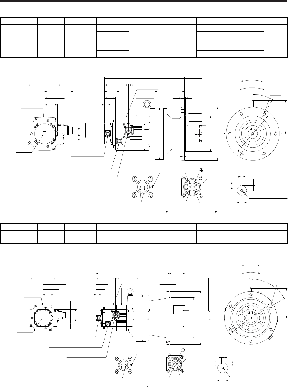
7. HG-SR SERIES
7 - 38
Model Output [kW] Reducer model Reduction ratio Brake static friction torque [N•m] Moment of inertia J [× 10-4 kg•m2] Mass [kg]
HG-SR102BG1
HG-SR1024BG1 1.0
1/6
8.5
17.0
32
1/11 15.5
CNVM-6120 1/17 15.1
1/29 14.8
1/35 14.8
[Unit: mm]
Caution plate
Motor plate
29
95.2
Electromagnetic brake
connector
CMV1-R2P
79.9
59
13
58
13.5
□130
112.5
50.9
Caution
plate
316
43.5
20.9
Bottom Top
TopBottom
Motor plate
Encoder connector
CMV1-R10P
Power supply connector
MS3102A18-10P
U
W
V
Power supply connector
Motor flange direction
Key
Electromagnetic brake
Electromagnetic brake connector
Motor flange direction
Main key
position mark
(Side view of motor only)
5
8
10
φ38h6
Shaft section view AA
M8 Screw hole depth 20
Caution plate
φ180
6-φ11
69
117
55
φ140f8
φ210
50
φ204
A
A
132
30°
13 4
(PE)
BC41187*
For reverse rotation command
For forward rotation command
Rotation direction
Model Output [kW] Reducer model Reduction ratio Brake static friction torque [N•m] Moment of inertia J [× 10-4 kg•m2] Mass [kg]
HG-SR102BG1
HG-SR1024BG1 1.0 CHVM-6130 1/43 8.5 16.0 51
[Unit: mm]
29
95.2
Electromagnetic brake connector
CMV1-R2P
79.9
59
13
58
13.5
□130
112.5
50.9
Caution
plate
361.5
43.5
20.9
Top
Top
Motor plate
Encoder connector
CMV1-R10P
Power supply connector
MS3102A18-10P
U
W
V
Power supply connector
Motor flange direction
Key
Electromagnetic brake
Electromagnetic brake connector
Motor flange direction
Main key
position mark
(Side view of motor only)
φ50h6
5.5
9
14
Shaft section view AA
M10 Screw hole depth 18
φ230
76
164
φ200f8
φ260
15 4
φ230
145
60°
208
6-φ11
56
A
A
70
For reverse rotation command
For forward rotation command
Rotation direction
(PE)
BC41188*
Caution plate
Motor plate
Caution plate
Bottom
Bottom
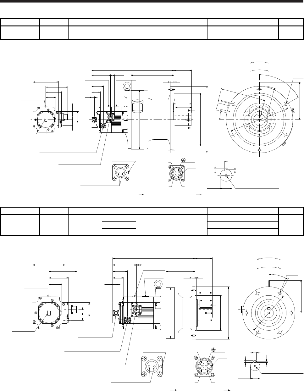
7. HG-SR SERIES
7 - 39
Model Output [kW] Reducer model Reduction ratio Brake static friction torque [N•m] Moment of inertia J [× 10-4 kg•m2] Mass [kg]
HG-SR102BG1
HG-SR1024BG1 1.0 CHVM-6160 1/59 8.5 21.3 83
[Unit: mm]
29
95.2
Electromagnetic brake connector
CMV1-R2P
79.9
59
13
58
13.5
□130
112.5
50.9
Caution plate
419
43.5
20.9
Motor plate
Encoder connector
CMV1-R10P
Power supply connector
MS3102A18-10P
U
W
V
Power supply connector
Motor flange direction
Key
Electromagnetic brake
Electromagnetic brake connector
Motor flange direction
Main key
position mark
(Side view of motor only)
6-φ11
192
φ300
219
89
φ270f8
φ340
φ310
60°
20 4
228
15°
175
90
A
A
80
Caution plate
7
M10 Screw hole depth 18
φ60h6
11
18
Shaft section view AA
(PE)
BC41189*
For reverse rotation command
For forward rotation command
Rotation direction
Top
Top
Caution plate
Motor plate
Bottom
Bottom
Model Output [kW] Reducer model Reduction ratio Brake static friction torque [N•m] Moment of inertia J [× 10-4 kg•m2] Mass [kg]
HG-SR152BG1
HG-SR1524BG1 1.5
1/6
8.5
21.4
33
CNVM-6120 1/11 19.9
1/17 19.5
[Unit: mm]
Caution plate
Motor plate
29
95.2
Electromagnetic brake connector
CMV1-R2P
79.9
59
13
58
13.5
□130
112.5
50.9
Caution plate
330
43.5
20.9
Bottom Top
Top
Bottom
Motor plate
Encoder connector
CMV1-R10P
Power supply connector
MS3102A18-10P
U
W
V
Power supply connector
Motor flange direction
Key
Electromagnetic brake
Electromagnetic brake connector
Motor flange direction
Main key
position mark
(Side view of motor only)
5
8
10
φ38h6
Shaft section view AA
M8 Screw hole depth 20
Caution plate
φ180
6-φ11
69
117
55
φ140f8
φ210
50
φ204
A
A
132
30°
13 4
For reverse rotation command
For forward rotation command
Rotation direction
(PE)
BC41190*
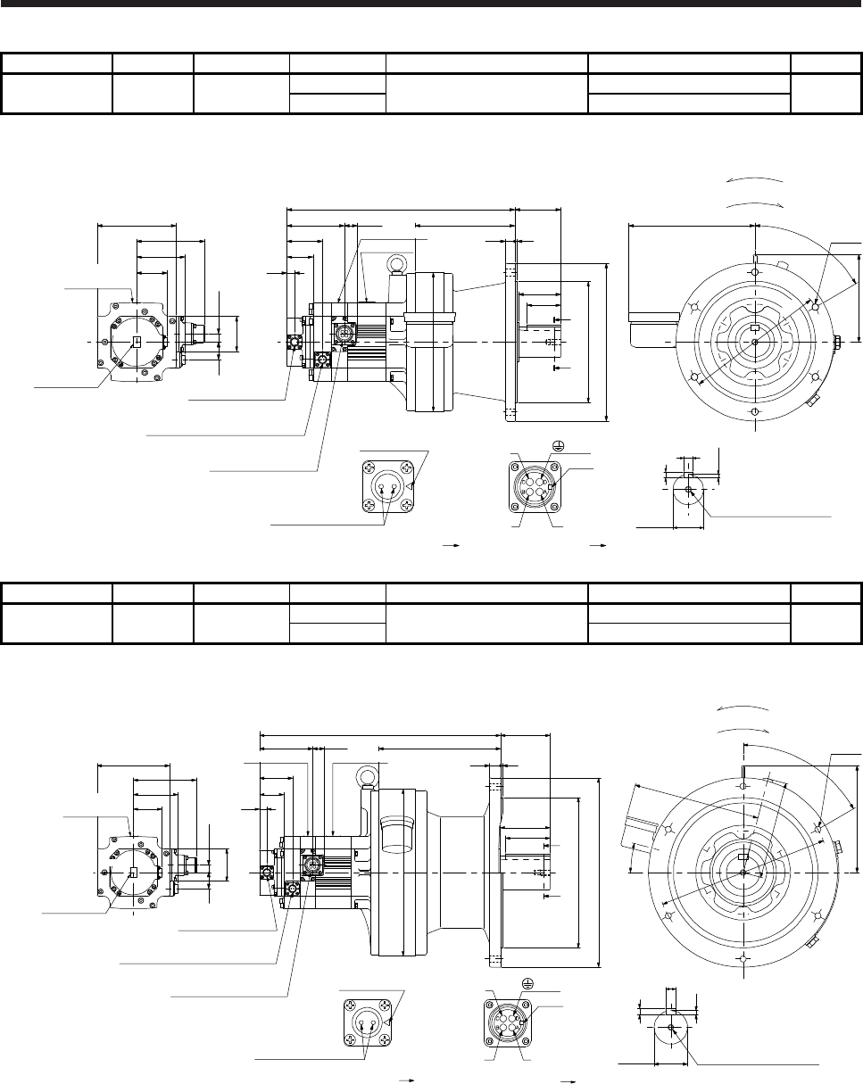
7. HG-SR SERIES
7 - 40
Model Output [kW] Reducer model Reduction ratio Brake static friction torque [N•m] Moment of inertia J [× 10-4 kg•m2] Mass [kg]
HG-SR152BG1
HG-SR1524BG1 1.5 CHVM-6130 1/29 8.5 20.6 52
1/35 20.5
[Unit: mm]
Bottom
TopBottom
Top
Caution plate
Motor plate
29
95.2
Electromagnetic brake connector
CMV1-R2P
79.9
59
13
58
13.5
□130
112.5
50.9
Caution plate
375.5
43.5
20.9
Motor plate
Encoder connector
CMV1-R10P
Electromagnetic brake
MS3102A18-10P
U
W
V
Power supply connector
Motor flange direction
Key
Electromagnetic brake
Electromagnetic brake connector
Motor flange direction
Main key
position mark
(Side view of motor only)
φ50h6
5.5
9
14
Shaft section view AA
M10 Screw hole depth 18
φ230
76
164
φ200f8
φ260
15 4
eφ230
145
60°
208
6-φ11
56
A
70
Caution plate
A
(PE)
BC41191*
For reverse rotation command
For forward rotation command
Rotation direction
Model Output [kW] Reducer model Reduction ratio Brake static friction torque [N•m] Moment of inertia J [× 10-4 kg•m2] Mass [kg]
HG-SR152BG1
HG-SR1524BG1 1.5 CHVM-6160 1/43 8.5 25.8 84
1/59 25.7
[Unit: mm]
Caution plate
Motor plate
29
95.2
Electromagnetic brake connector
CMV1-R2P
79.9
59
13
58
13.5
□130
112.5
50.9
Caution plate
433
43.5
20.9
Motor plate
Encoder connector
CMV1-R10P
Power supply connector
MS3102A18-10P
U
W
V
Power supply connector
Motor flange direction
Key
Electromagnetic brake
Electromagnetic brake connector
Motor flange direction
Main key
position mark
(Side view of motor only)
6-φ11
192
φ300
219
89
φ270f8
φ340
φ310
60°
20 4
228
15°
175
90
A
A
80
Caution plate
7
M10 Screw hole depth 18
φ60h6
11
18
Shaft section view AA
(PE)
BC41192*
For reverse rotation command
For forward rotation command
Rotation direction
Top
Top
Bottom
Bottom
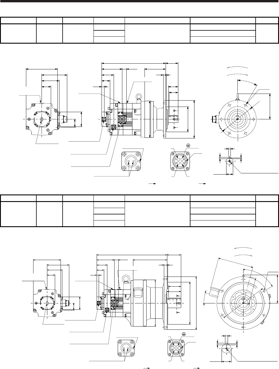
7. HG-SR SERIES
7 - 41
Model Output [kW] Reducer model Reduction ratio Brake static friction torque [N•m] Moment of inertia J [× 10-4 kg•m2] Mass [kg]
HG-SR202BG1
HG-SR2024BG1 2.0
1/6
44
59.4
42
CNVM-6120 1/11 57.8
1/17 57.5
[Unit: mm]
U
W
V
Power supply connector
Motor flange direction
Key
Electromagnetic brake
Electromagnetic brake connector
Motor flange direction
Main key
position mark
Shaft section view AA
5
10
8
φ38h6 M8 Screw hole depth 20
□176
96.9
140.9
Caution plate
44
Caution plate
Motor plate
50.9
82
(Side view of motor only)
φ204
6-φ11
φ180
142
30°
A
A
Caution plate
13
24.8113.2
66.5
45.5
117
4
69355
13
55
50
φ140f8
φ210
Power supply connector
MS3102A22-22P
Electromagnetic brake
connector
CMV1-R2P
Encoder connector
CMV1-R10P (PE)
BC41193*
Top
Top
Bottom
Bottom
For reverse rotation command
For forward rotation command
Rotation direction
Motor plate
Model Output [kW] Reducer model Reduction ratio Brake static friction torque [N•m] Moment of inertia J [× 10-4 kg•m2] Mass [kg]
HG-SR202BG1
HG-SR2024BG1 2.0
1/29
44
64.2
93
CHVM-6165 1/35 63.9
1/43 63.7
1/59 63.6
[Unit: mm]
Bottom
Bottom
U
W
V
Power supply connector
Motor flange direction
Key
Electromagnetic brake
Electromagnetic brake connector
Motor flange direction
Main key
position mark
M10 Screw hole depth 18
Shaft section view AA
18
11
7
φ60h6
□176
96.9
140.9
Caution plate
44
Caution plate
Motor plate
Top
50.9
Top
82
6-φ11
A
A
219
4
89452
φ300
80
90
φ270f8
φ340
181
60°
15°
228
175
φ310
(Side view of motor only)
Caution plate
13
24.8113.2
66.5
45.5 Motor plate
Power supply connector
Electromagnetic brake
connector
CMV1-R2P
MS3102A22-22P
Encoder connector
CMV1-R10P
20
(PE)
BC41194A
For reverse rotation command
For forward rotation command
Rotation direction
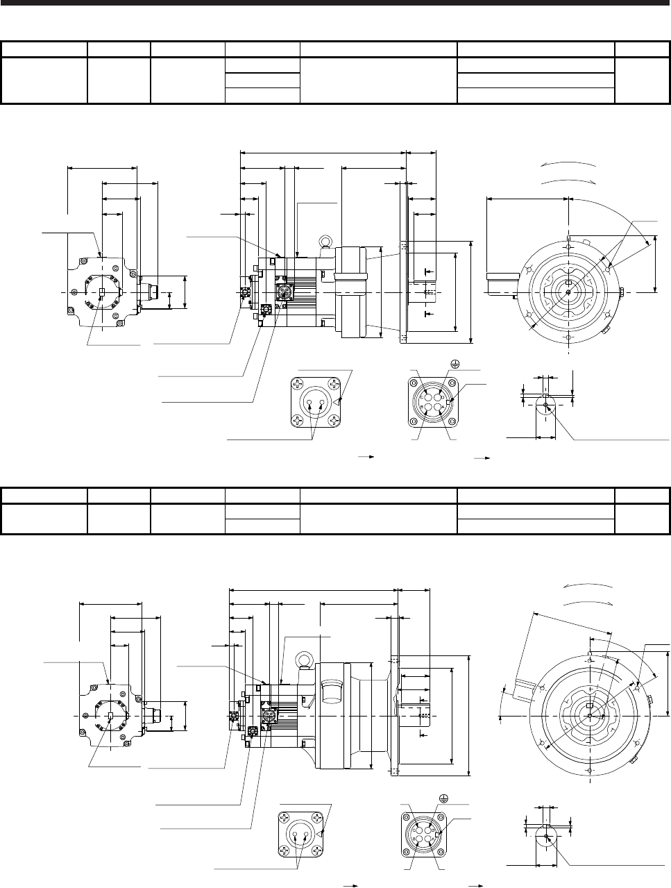
7. HG-SR SERIES
7 - 42
Model Output [kW] Reducer model Reduction ratio Brake static friction torque [N•m] Moment of inertia J [× 10-4 kg•m2] Mass [kg]
HG-SR352BG1
HG-SR3524BG1 3.5
1/6
44
96.5
66
CHVM-6135 1/11 92.2
1/17 90.9
[Unit: mm]
Bottom
Bottom
U
W
V
Power supply connector
Motor flange direction
Key
Electromagnetic brake
Electromagnetic brake connector
Motor flange direction
Main key
position mark
□176
96.9
140.9
Caution plate
44
Caution plate
Motor plate
Motor plate
Caution plate
13
24.8113.2
66.5
Power supply connector
MS3102A22-22P
Electromagnetic brake
connector
CMV1-R2P
Encoder connector
CMV1-R10P
Top
Shaft section view AA
50.9
45.5
Top
82
φ50h6 M10 Screw hole depth 18
14
9
5.5
A
A
6-φ11
4
15
76
164
56
70
φ200f8
φ260
145
208
60°
φ230
φ230
(Side view of motor only)
421.5
(PE)
BC41195*
For reverse rotation command
For forward rotation command
Rotation direction
Model Output [kW] Reducer model Reduction ratio Brake static friction torque [N•m] Moment of inertia J [× 10-4 kg•m2] Mass [kg]
HG-SR352BG1
HG-SR3524BG1 3.5 CHVM-6165 1/29 44 96.0 98
1/35 95.7
[Unit: mm]
Bottom
Bottom
U
W
V
Power supply connector
Motor flange direction
Key
Electromagnetic brake
Electromagnetic brake connector
Motor flange direction
Main key
position mark
□176
96.9
140.9
Caution plate
44
Caution plate
Motor plate
Motor plate
Caution plate
13
24.8113.2
66.5
Power supply connector
MS3102A22-22P
Electromagnetic brake
connector
CMV1-R2P
Encoder connector
CMV1-R10P
Top
50.9
45.5
Top
82
M10 Screw hole depth 18
Shaft section view AA
18
11
7
φ60h6
6-φ11
A
A
219
4
89476
20
φ300
80
90
φ270f8
φ340
181
60°
15°
228
175
φ310
(Side view of motor only)
(PE)
BC41196*
For reverse rotation command
For forward rotation command
Rotation direction
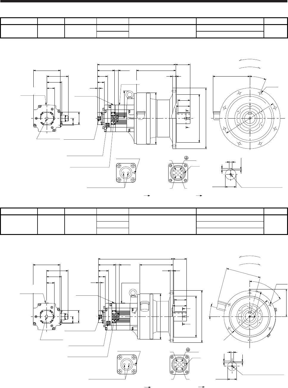
7. HG-SR SERIES
7 - 43
Model Output [kW] Reducer model Reduction ratio Brake static friction torque [N•m] Moment of inertia J [× 10-4 kg•m2] Mass [kg]
HG-SR352BG1
HG-SR3524BG1 3.5 CHVM-6175 1/43 44 114 140
1/59 113
[Unit: mm]
Bottom
Bottom
U
W
V
Power supply connector
Motor flange direction
Key
Electromagnetic brake
Electromagnetic brake connector
Motor flange direction
Main key
position mark
M12 Screw hole depth 24
□176
96.9
140.9
Caution plate
44
Caution plate
Motor plate
Motor plate
Caution plate
13
24.8113.2
66.5
Power supply connector
MS3102A22-22P
Electromagnetic brake
connector
CMV1-R2P
Encoder connector
CMV1-R10P
Top
Shaft section view AA
50.9
45.5
20
12
7.5
φ70h6
Top
82
φ316f8
8-φ14
A
A
80
90
258
5
22
94515.5
φ400
243
22.5°
φ360
φ340
181
(Side view of motor only)
(PE)
BC41197*
For reverse rotation command
For forward rotation command
Rotation direction
Model Output [kW] Reducer model Reduction ratio Brake static friction torque [N•m] Moment of inertia J [× 10-4 kg•m2] Mass [kg]
HG-SR502BG1
HG-SR5024BG1 5.0
1/6
44
135
102
CHVM-6165 1/11 123
1/17 119
[Unit: mm]
Bottom
Bottom
U
W
V
Power supply connector
Motor flange direction
Key
Electromagnetic brake
Electromagnetic brake connector
Motor flange direction
Main key
position mark
□176
96.9
140.9
Caution plate
44
82
Caution plate
Motor plate
Motor plate
Caution plate
13
24.8113.2
66.5
Top
50.9
45.5
Top
A
φ300
219
20 4
80
90
φ340
φ270f8
89
A
φ310
60°
181
15°
228
175
6-φ11
492
18
7
11
Shaft section view AA
φ60h6
M10 Screw hole depth 18
(Side view of motor only)
Encoder connector
CMV1-R10P
Electromagnetic brake
connector
CMV1-R2P
Power supply connector
MS3102A22-22P
(PE)
BC41198*
For reverse rotation command
For forward rotation command
Rotation direction
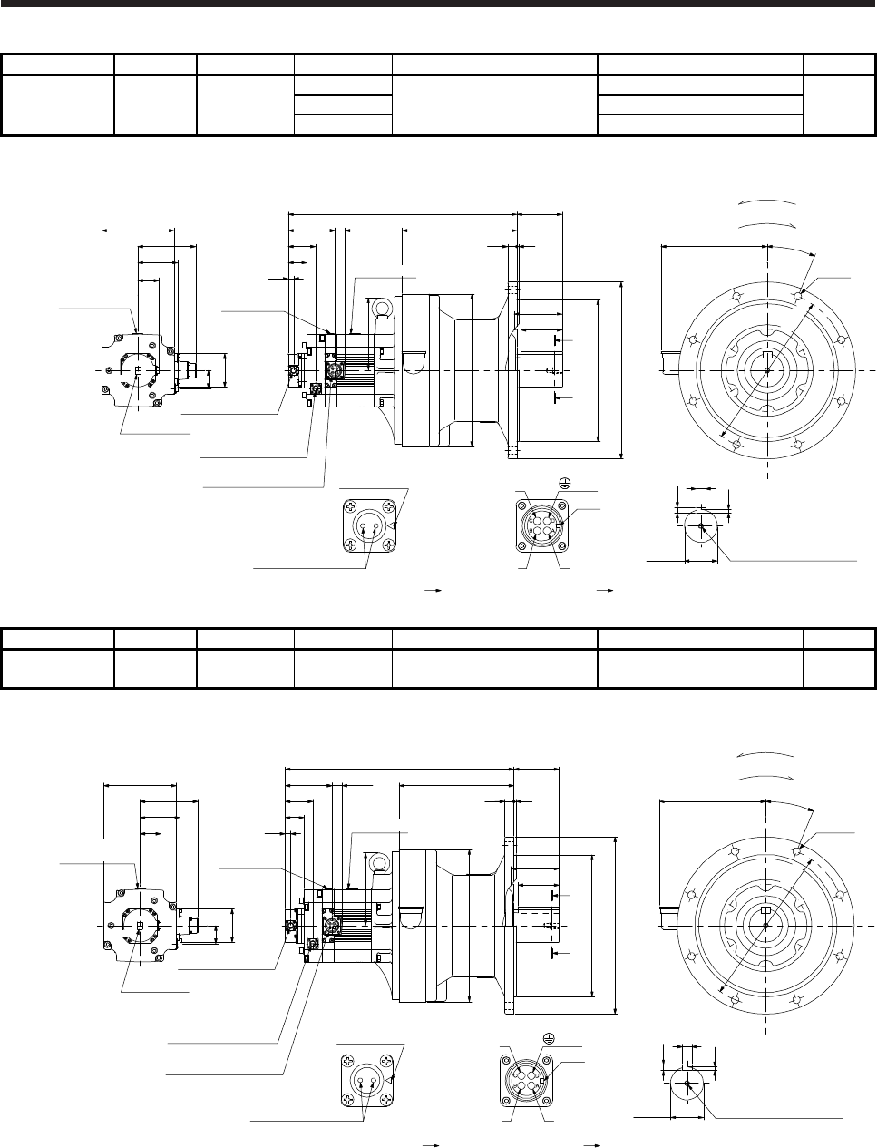
7. HG-SR SERIES
7 - 44
Model Output [kW] Reducer model Reduction ratio Brake static friction torque [N•m] Moment of inertia J [× 10-4 kg•m2] Mass [kg]
HG-SR502BG1
HG-SR5024BG1 5.0
1/29
44
150
171
CHVM-6180 1/35 150
1/43 149
[Unit: mm]
Bottom
Bottom
U
W
V
Power supply connector
Motor flange direction
key
Electromagnetic brake
Electromagnetic brake connector
Motor flange direction
Main key
position mark
176
M12 Screw hole depth 24
φ345f8
φ430
22 5
555.5 110
100
258
8-φ18
279
φ370
□176
96.9
140.9
Caution plate
44
82
Caution plate
Motor plate
Motor plate
Caution plate
13
24.8
113.2
66.5
Top
A
A
Shaft section view AA
50.9
110
45.5
22
14
9
φ80h6
Top
22.5°
(Side view of motor only)
Encoder connector
CMV1-R10P
Electromagnetic brake
connector
CMV1-R2P
Power supply connector
MS3102A22-22P (PE)
BC41199*
For reverse rotation command
For forward rotation command
Rotation direction
φ390
Model Output [kW] Reducer model Reduction ratio Brake static friction torque [N•m] Moment of inertia J [× 10-4 kg•m2] Mass [kg]
HG-SR502BG1
HG-SR5024BG1 5.0 CHVM-6185 1/59 44 147 171
[Unit: mm]
Bottom
Bottom
U
W
V
Power supply connector
Motor flange direction
Key
Electromagnetic brake
Electromagnetic brake connector
Motor flange direction
Main key
position mark
176
M12 Screw hole depth 24
φ345f8
φ430
22 5
555.5 110
100
258
8-φ18
279
φ370
□176
96.9
140.9
Caution plate
44
82
Caution plate
Motor plate
Motor plate
Caution plate
13
24.8
113.2
66.5
Top
A
A
Shaft section view AA
50.9
110
45.5
22
14
9
φ80h6
Top
22.5°
(Side view of motor only)
Encoder connector
CMV1-R10P
Electromagnetic brake
connector
CMV1-R2P
Power supply connector
MS3102A22-22P
(PE)
BC41200*
For reverse rotation command
For forward rotation command
Rotation direction
φ390
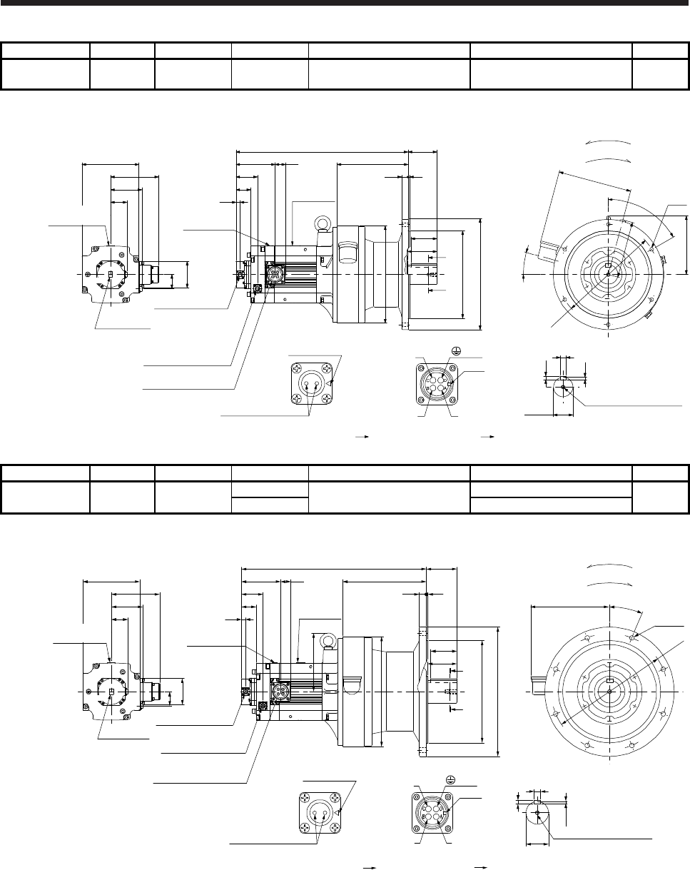
7. HG-SR SERIES
7 - 45
Model Output [kW] Reducer model Reduction ratio Brake static friction torque [N•m] Moment of inertia J [× 10-4 kg•m2] Mass [kg]
HG-SR702BG1
HG-SR7024BG1 7.0 CHVM-6165 1/6 44 187 109
[Unit: mm]
U
W
V
Power supply connector
Motor flange direction
Key
Electromagnetic brake
Electromagnetic brake connector
Motor flange direction
Main key
position mark
532
□176
96.9
149.1
Caution plate
44
82
Caution plate
Motor plate
Motor plate
Caution plate
13
32
121.2
66.5
Top
50.9
45.5
Top
Shaft section view AA
φ310
60°
181
15°
228
175
6-φ11
18
7
11
φ60h6 M10 Screw hole depth 18
A
φ300
219
20 4
80
90
φ340
φ270f8
89
A
(Side view of motor only)
Encoder connector
CMV1-R10P
Electromagnetic brake
connector
CMV1-R2P
Power supply connector
MS3102A32-17P
(PE)
BC41201*
Bottom
Bottom
For reverse rotation command
For forward rotation command
Rotation direction
Model Output [kW] Reducer model Reduction ratio Brake static friction torque [N•m] Moment of inertia J [× 10-4 kg•m2] Mass [kg]
HG-SR702BG1
HG-SR7024BG1 7.0 CHVM-6170 1/11 44 199 151
1/17 192
[Unit: mm]
U
W
V
Power supply connector
Motor flange direction
key
Electromagnetic brake
Electromagnetic brake connector
Motor flange direction
Main key
position mark
571.5
□176
96.9
149.1
Caution plate
44
82
Caution plate
Motor plate
Motor plate
Caution plate
13
32121.2
66.5
Top
50.9
45.5
Top
φ360
8-φ14
243
22.5°
7.5
20
12
M12 Screw hole depth 24
φ70h6
Shaft section view AA
90
φ400
φ316f8
80
φ340
A
94
258
522
A
181
(Side view of motor only)
Encoder connector
CMV1-R10P
Electromagnetic brake
connector
CMV1-R2P
Power supply connector
MS3102A32-17P
BC41202*
(PE)
Bottom
Bottom
For reverse rotation command
For forward rotation command
Rotation direction
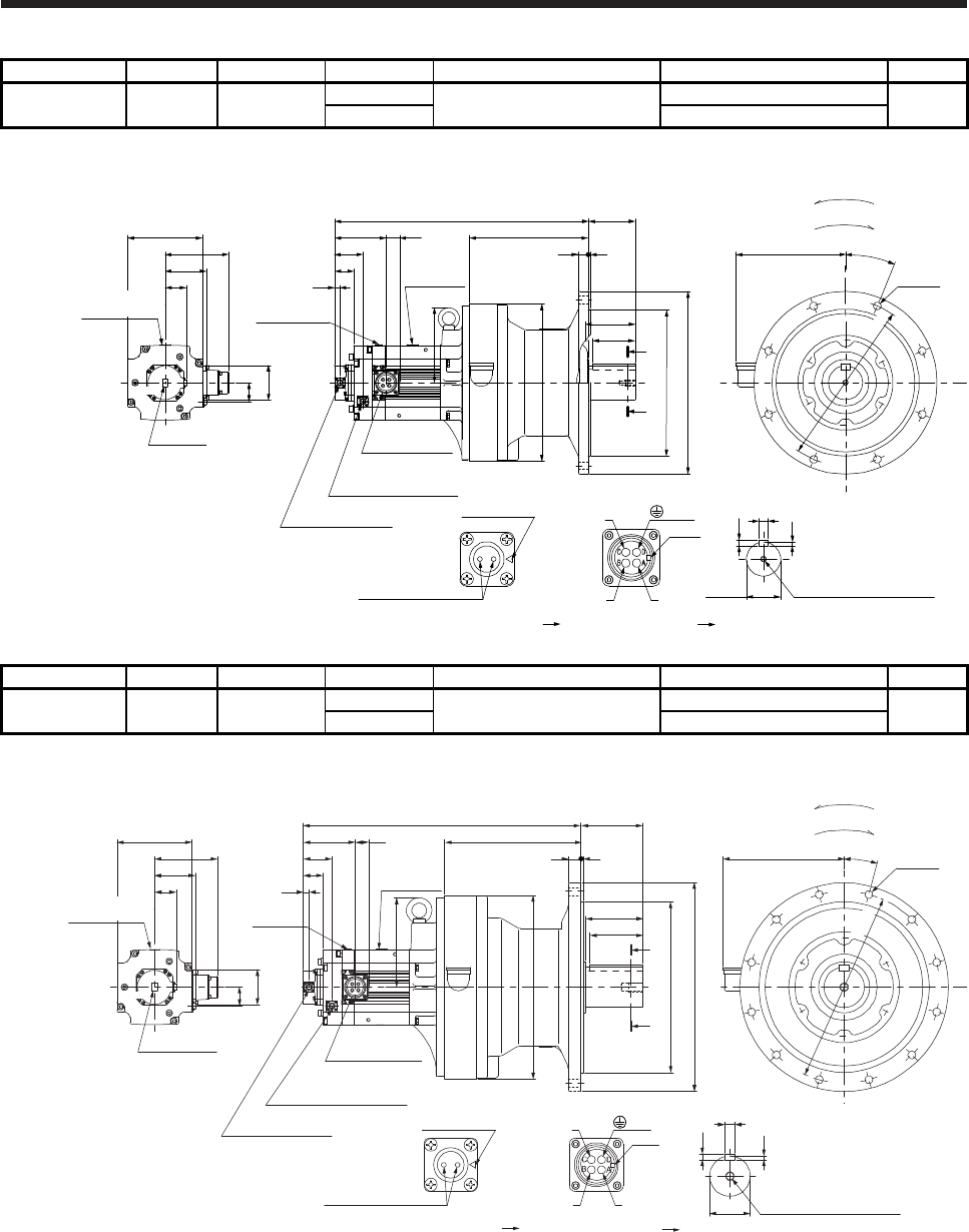
7. HG-SR SERIES
7 - 46
Model Output [kW] Reducer model Reduction ratio Brake static friction torque [N•m] Moment of inertia J [× 10-4 kg•m2] Mass [kg]
HG-SR702BG1
HG-SR7024BG1 7.0 CHVM-6180 1/29 44 202 178
1/35 201
[Unit: mm]
U
W
V
Key
(PE)
Power supply connector
Motor flange direction
Electromagnetic brake
Electromagnetic brake connector
Motor flange direction
Main key
position mark
595.5
□176
96.9
149.1
Caution plate
44
82
Caution plate
Motor plate
Motor plate
Caution plate
13
32121.2
66.5
Power supply
connector
MS3102A32-17P
Electromagnetic brake
connector
CMV1-R2P
Encoder connector
CMV1-R10P
Top
50.9
45.5
Top
176
φ345f8
φ430
22 5
110
100
279
φ370
A
A
110
258
8-φ18
22.5°
M12 Screw hole depth 24
Shaft section view AA
22
14
9
φ80h6
(Side view of motor only)
BC41203*
φ390
Bottom
Bottom
For reverse rotation command
For forward rotation command
Rotation direction
Model Output [kW] Reducer model Reduction ratio Brake static friction torque [N•m] Moment of inertia J [× 10-4 kg•m2] Mass [kg]
HG-SR702BG1
HG-SR7024BG1 7.0 CHVM-6195 1/43 44 277 246
1/59 275
[Unit: mm]
BC41204*
U
W
V
Power supply connector
Motor flange direction
Key
Electromagnetic brake
Electromagnetic brake connector
Motor flange direction
Main key
position mark
210
9
14
25
φ95h6 M20 Screw hole depth 34
φ400f8
φ490
30 6
651.5 145
125
285
15°
12-φ18
320
φ430
□176
96.9
149.1
Caution plate
44
82
Caution plate
Motor plate
Motor plate
Caution
plate
13
32
121.2
66.5
Power supply
connector
MS3102A32-17P
Electromagnetic brake
connector
CMV1-R2P
Encoder connector
CMV1-R10P
Top
A
A
Shaft section view AA
50.9
135
45.5
Top
(Side view of motor only)
(PE)
φ450
Bottom
Bottom
For reverse rotation command
For forward rotation command
Rotation direction
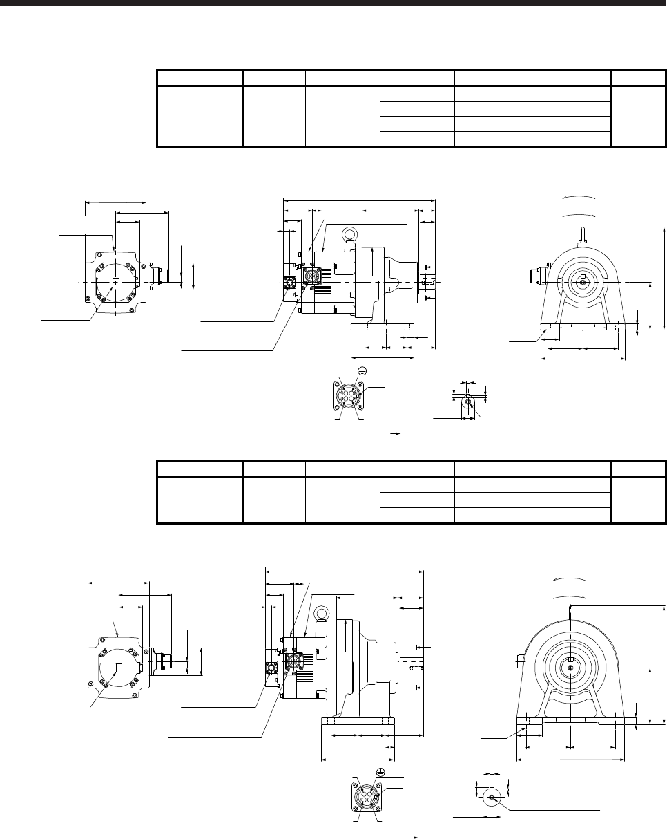
7. HG-SR SERIES
7 - 47
7.7.5 For general industrial machine with a reducer (foot-mounting/without an electromagnetic brake)
Model Output [kW] Reducer model Reduction ratio Moment of inertia J [× 10-4 kg•m2] Mass [kg]
HG-SR52G1H
HG-SR524G1H 0.5
1/6 8.08
20
CNHM-6100 1/11 7.65
1/17 7.53
1/29 7.47
[Unit: mm]
60.7
58
13.5
□130
112.5
50.9
Caution plate
Motor plate
323
20.9
U
W
V
Power supply connector
Motor flange direction
Key
Caution
plate
(Side view of motor only)
13
38.2
12
100
219
40 75 75
180
4-φ11
15
45 45
135
60
121 35
32
A
A
φ150
Shaft section view AA
φ28h6
4
7
8
M8 Screw hole depth 20
Encoder connector
CMV1-R10P
Power supply connector
MS3102A18-10P
BC41137*
(PE)
Top
Top
Bottom
Bottom
For reverse rotation command
For forward rotation command
Rotation direction
Caution plate
Motor plate
Model Output [kW] Reducer model Reduction ratio Moment of inertia J [× 10-4 kg•m2] Mass [kg]
HG-SR52G1H
HG-SR524G1H 0.5
1/35 8.26
28
CNHM-6120 1/43 8.22
1/59 8.18
[Unit: mm]
Shaft section view AA
φ204
55
131
8
5
10
50
A
M8 Screw hole depth 20
Caution plate
Motor plate
60.7
58
13.5
□130
112.5
50.9
Caution plate
Motor plate
336.5
20.9
U
W
V
Power supply connector
Motor flange direction
Key
252
120
95
230
95
55
15
4-φ14
155
57.5 57.5
20
82
Caution plate
(Side view of motor only)
13
38.2
A
Encoder connector
CMV1-R10P
Power supply connector
MS3102A18-10P
BC41138*
(PE)
φ38h6
Top
TopBottom
Bottom
For reverse rotation command
For forward rotation command
Rotation direction
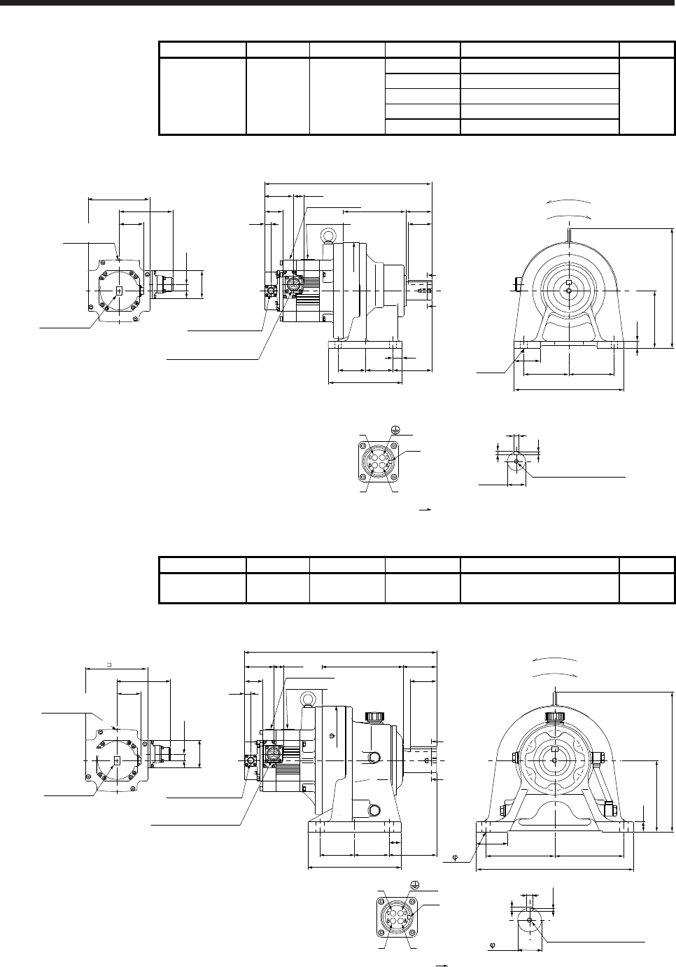
7. HG-SR SERIES
7 - 48
Model Output [kW] Reducer model Reduction ratio Moment of inertia J [× 10-4 kg•m2] Mass [kg]
HG-SR102G1H
HG-SR1024G1H 1.0
1/6 14.8
31
1/11 13.3
CNHM-6120 1/17 12.9
1/29 12.6
1/35 12.6
[Unit: mm]
38.2
13
58
13.5
□130
112.5
50.9
Caution plate
350.5
U
W
V
Power supply connector
Motor flange direction
Key
(Side view of motor only)
Motor plate
Caution plate
20.960.7
Encoder connector
CMV1-R10P
Power supply connector
MS3102A18-10P
5
8
10
φ38h6
Shaft section view AA
M8 Screw hole depth 20
20
57.5 57.5 82
155
55
95 95
230
131 55
50
A
A
4-φ14
15
120
252
φ204
BC41139*
(PE)
Top
Top
Bottom
Bottom
For reverse rotation command
For forward rotation command
Rotation direction
Caution plate
Motor plate
Model Output [kW] Reducer model Reduction ratio Moment of inertia J [× 10-4 kg•m2] Mass [kg]
HG-SR102G1H
HG-SR1024G1H 1.0 CHHM-6130 1/43 13.8 50
[Unit: mm]
Caution plate
Motor plate
38.2
13
58
13.5
130
112.5
50.9
Caution plate
403
Bottom Top
Top
Bottom
U
W
V
Power supply connector
Motor flange direction
Key
(Side view of motor only)
Motor plate
Caution plate
20.960.7
Encoder connector
CMV1-R10P
Power supply connector
MS3102A18-10P
170 70
56
22
150
295
65
145 145
330
25
72.5 72.5
195
100 4- 18
A
A
230
50h6
5.5
9
14
Shaft section view AA
M10 Screw hole depth 18
For reverse rotation command
For forward rotation command
Rotation direction
BC41140*
(PE)
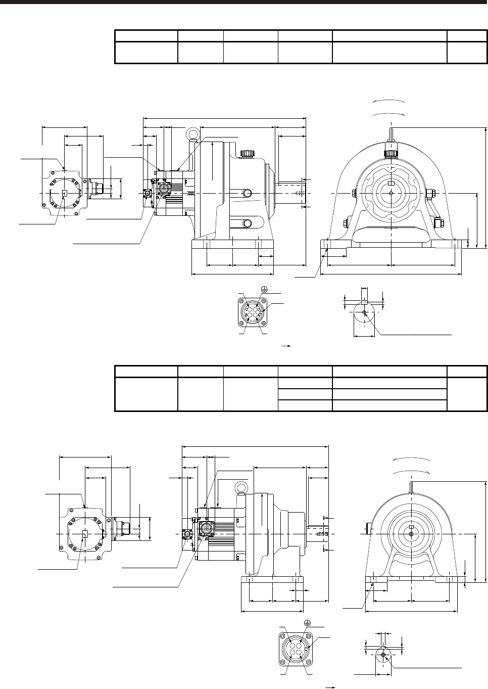
7. HG-SR SERIES
7 - 49
Model Output [kW] Reducer model Reduction ratio Moment of inertia J [× 10-4 kg•m2] Mass [kg]
HG-SR102G1H
HG-SR1024G1H 1.0 CHHM-6160 1/59 19.1 86
[Unit: mm]
38.2
13
58
13.5
□130
112.5
50.9
Caution plate
473.5
BC41141*
25
160
352
75
185 185
410
4-φ18
7
M10 Screw hole depth 18
φ60h6
11
18
Shaft section view AA
U
W
V
Power supply connector
Motor flange direction
Key
(Side view of motor only)
218 90
80
44
75 75 139
238
φ300
20.960.7
Encoder connector
CMV1-R10P
Power supply connector
MS3102A18-10P
Caution plate
A
A
(PE)
Caution plate
Motor plate
Motor plate
TopBottom
TopBottom
For reverse rotation command
For forward rotation command
Rotation direction
Model Output [kW] Reducer model Reduction ratio Moment of inertia J [× 10-4 kg•m2] Mass [kg]
HG-SR152G1H
HG-SR1524G1H 1.5
1/6 19.2
32
CNHM-6120 1/11 17.7
1/17 17.3
[Unit: mm]
AB
CD
38.2
13
58
13.5
□130
112.5
50.9
Caution plate
364.5
U
W
V
Power supply connector
Motor flange direction
Key
(Side view of motor only)
Motor plate
Caution plate
20.960.7
Encoder connector
CMV1-R10P
Power supply connector
MS3102A18-10P
5
8
10
φ38h6
Shaft section view AA
M8 Screw hole depth 20
20
57.5 57.5 82
155
55
95 95
230
131 55
50
4-φ14
15
120
252
φ204
A
A
BC41142*
(PE)
TopBottom
TopBottom
For reverse rotation command
For forward rotation command
Rotation direction
Caution plate
Motor plate
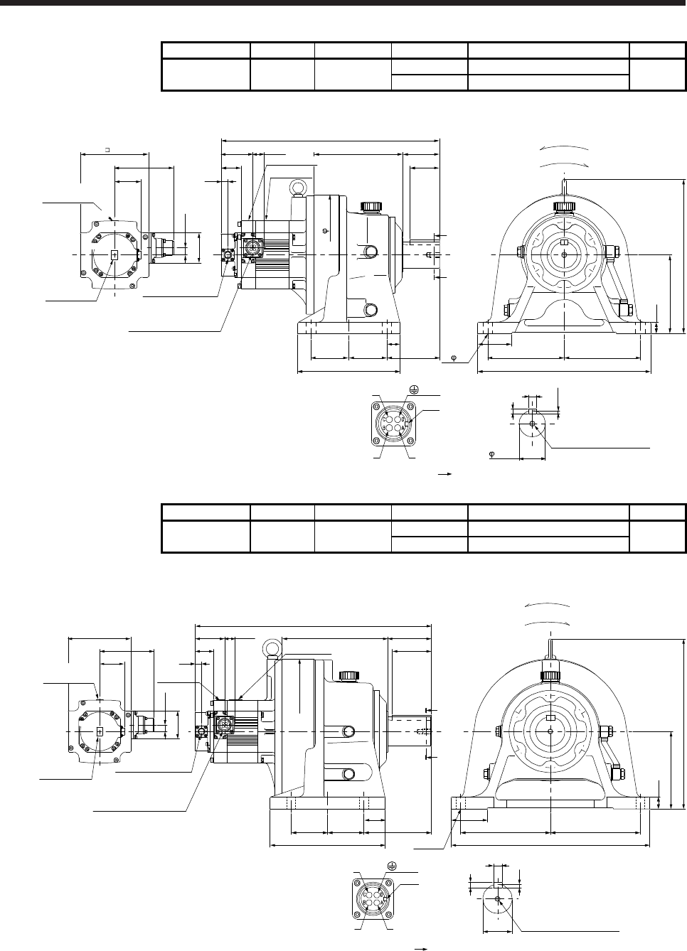
7. HG-SR SERIES
7 - 50
Model Output [kW] Reducer model Reduction ratio Moment of inertia J [× 10-4 kg•m2] Mass [kg]
HG-SR152G1H
HG-SR1524G1H 1.5 CHHM-6130 1/29 18.4
51
1/35 18.3
[Unit: mm]
38.2
13
58
13.5
130
112.5
50.9
Caution plate
417
Bottom Top
Top
Bottom
U
W
V
Power supply connector
Motor flange direction
(PE)
Key
(Side view of motor only)
Motor plate
20.960.7
Encoder connector
CMV1-R10P
Power supply connector
MS3102A18-10P
170 70
56
22
150
295
65
145 145
330
25
72.5 72.5
195
100 4- 18
A
A
230
50h6
5.5
9
14
Shaft section view AA
M10 Screw hole depth 18
For reverse rotation command
For forward rotation command
Rotation direction
BC41143*
Caution plate
Motor plate
Caution plate
Model Output [kW] Reducer model Reduction ratio Moment of inertia J [× 10-4 kg•m2] Mass [kg]
HG-SR152G1H
HG-SR1524G1H 1.5 CHHM-6160 1/43 23.6
87
1/59 23.5
[Unit: mm]
38.2
13
58
13.5
□130
112.5
50.9
Caution plate
487.5
25
160
352
75
185 185
410
4-φ18
7
M10 Screw hole depth 18
φ60h6
11
18
Shaft section view AA
U
W
V
Power supply connector
Motor flange direction
Key
(Side view of motor only)
218 90
80
44
75 75 139
238
A
A
φ300
Motor plate
20.960.7
Encoder connector
CMV1-R10P
Power supply connector
MS3102A18-10P
BC41144*
(PE)
Caution plate
Motor plate Caution
plate
For reverse rotation command
For forward rotation command
Rotation direction
TopBottom
TopBottom
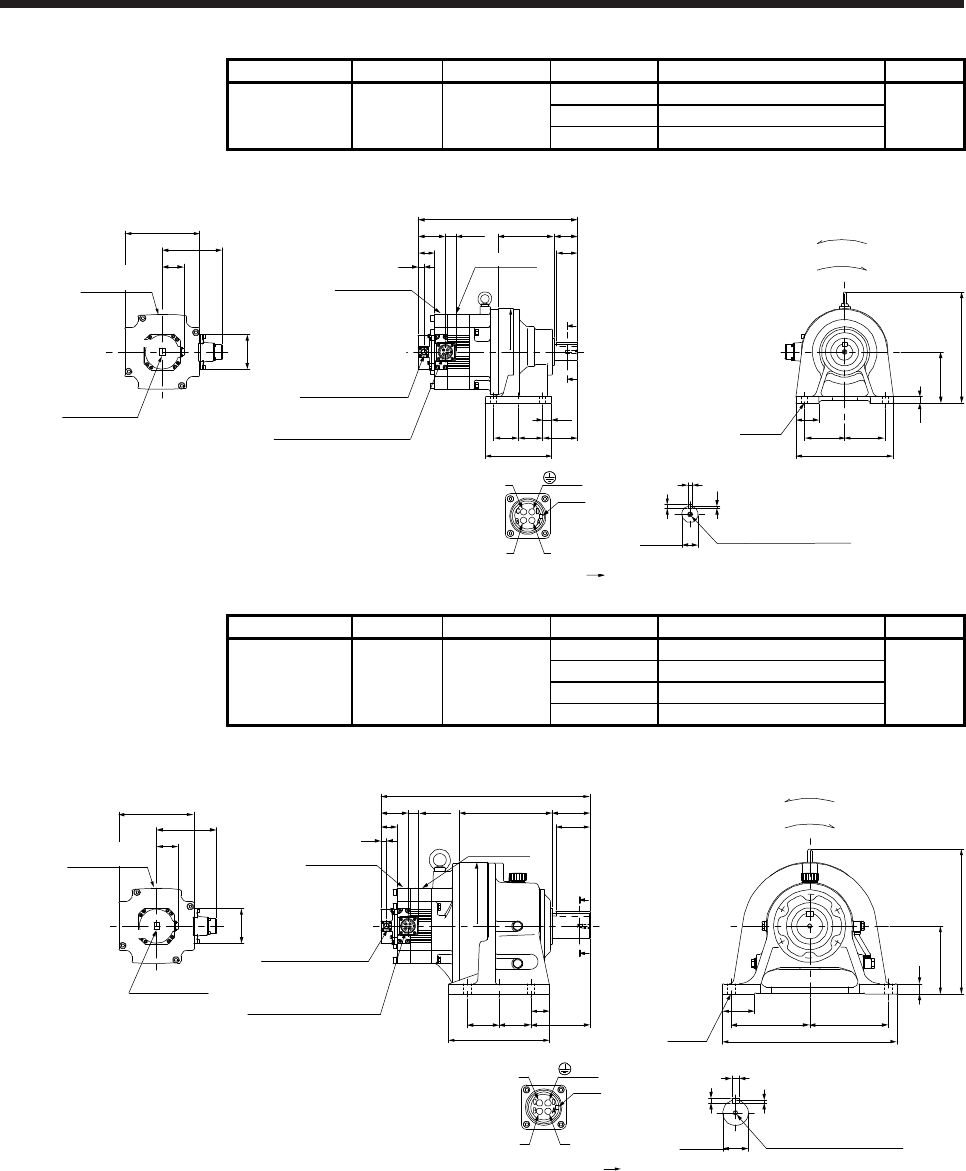
7. HG-SR SERIES
7 - 51
Model Output [kW] Reducer model Reduction ratio Moment of inertia J [× 10-4 kg•m2] Mass [kg]
HG-SR202G1H
HG-SR2024G1H 2.0
1/6 50.0
37
CNHM-6120 1/11 48.4
1/17 48.1
[Unit: mm]
U
W
V
Power supply connector
Motor flange direction
Key
Shaft section view AA
57.557.5
20
82
155
A
A
131
50
55
φ204
4-φ14 95
55
230
95
15
262
120
5
10
8
φ38h6 M8 Screw hole depth 20
374.5
13
24.8
63.7
38.5
Caution plate
(Side view of motor only)
□176
140.9
Caution plate
50.9
82
Power supply connector
MS3102A22-22P
Encoder connector
CMV1-R10P
BC41145*
(PE)
Top
TopBottom
Bottom
Caution plate
Motor plate
Motor plate
For reverse rotation command
For forward rotation command
Rotation direction
Model Output [kW] Reducer model Reduction ratio Moment of inertia J [× 10-4 kg•m2] Mass [kg]
HG-SR202G1H
HG-SR2024G1H 2.0
1/29 54.8
92
CHHM-6165 1/35 54.5
1/43 54.3
1/59 54.2
[Unit: mm]
U
W
V
Power supply connector
Motor flange direction
Key
M10 Screw hole depth 18
Shaft section view AA
18
11
7
4-φ18 185
75
410
185
25
341
160
75 75
44
139
238
A
A
218
80
90
(Side view of motor only)
□176
140.9
Caution plate
Caution plate
Motor plate
Top
50.9
Top
82
Caution plate
Power supply connector
MS3102A22-22P
Encoder connector
CMV1-R10P
13
24.8
63.7
38.5
Motor plate
491.5
φ300
BC41146*
(PE)
φ60h6
Bottom
Bottom
For reverse rotation command
For forward rotation command
Rotation direction
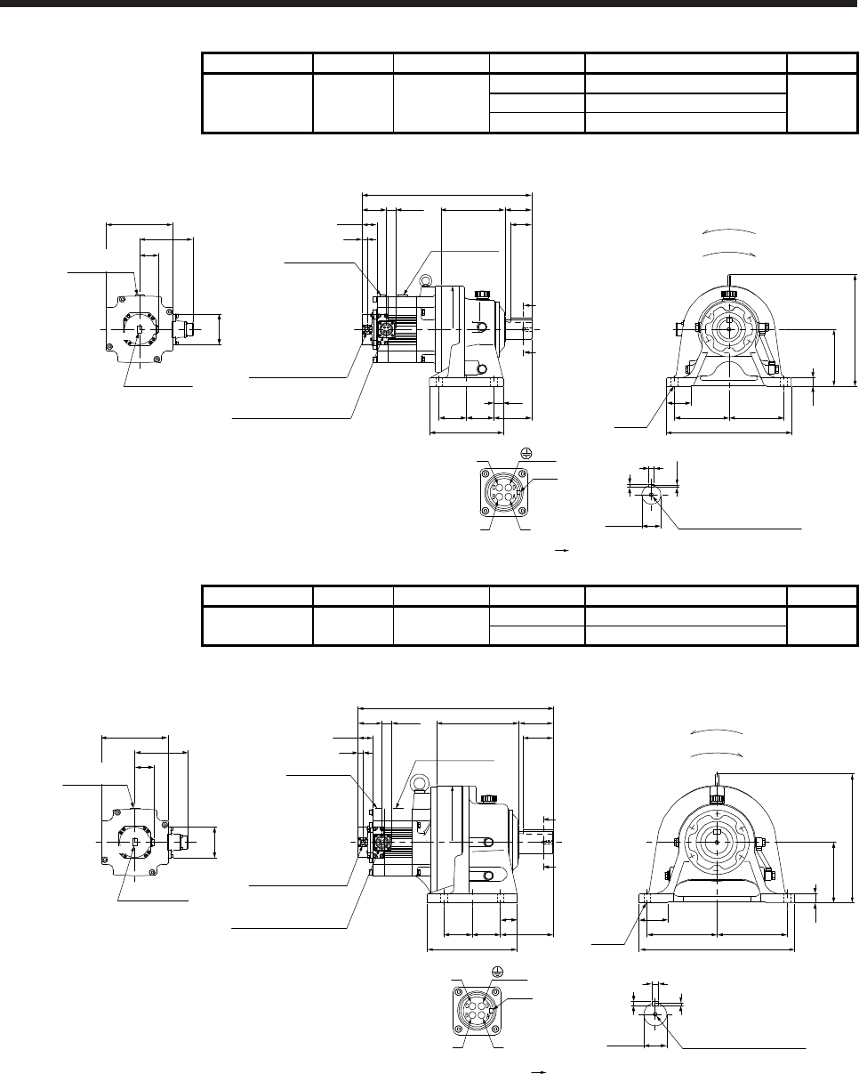
7. HG-SR SERIES
7 - 52
Model Output [kW] Reducer model Reduction ratio Moment of inertia J [× 10-4 kg•m2] Mass [kg]
HG-SR352G1H
HG-SR3524G1H 3.5
1/6 87.1
61
CHHM-6135 1/11 82.8
1/17 81.5
[Unit: mm]
U
W
V
Power supply connector
Motor flange direction
Key
13
24.8
63.7
38.5
Shaft section view AA
φ50h6 M10 Screw hole depth 18
14
9
5.5
72.5 72.5
25
100
195
170
56
70
448
φ230
4-φ18 145
65
330
145
22
295
150
□176
140.9
Caution plate
Caution plate
Motor plate
Top
50.9
Top
Bottom
82
(Side view of motor only)
Caution plate
Power supply connector
MS3102A22-22P
Encoder connector
CMV1-R10P
Motor plate
A
A
BC41147*
(PE)
Bottom
For reverse rotation command
For forward rotation command
Rotation direction
Model Output [kW] Reducer model Reduction ratio Moment of inertia J [× 10-4 kg•m2] Mass [kg]
HG-SR352G1H
HG-SR3524G1H 3.5 CHHM-6165 1/29 86.6
97
1/35 86.3
[Unit: mm]
U
W
V
Power supply connector
Motor flange direction
Key
M10 Screw hole depth 18
□176
140.9
Caution plate
Caution plate
Motor plate
13
24.863.7
38.5
Top
Shaft section view AA
50.9
18
11
7
Top
82
4-φ18 185
75
410
185
25
341
160
75 75
44
139
238
A
A
218
80
90
φ300
(Side view of motor only) Power supply connector
MS3102A22-22P
Encoder connector
CMV1-R10P
Motor plate
Caution plate
515.5
BC41148*
φ60h6
(PE)
Bottom
Bottom
For reverse rotation command
For forward rotation command
Rotation direction
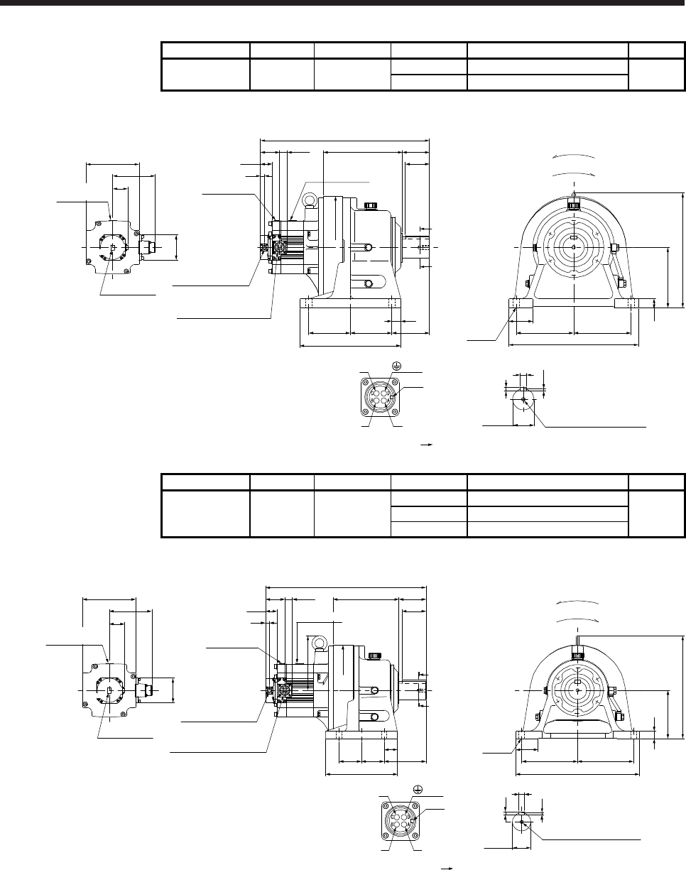
7. HG-SR SERIES
7 - 53
Model Output [kW] Reducer model Reduction ratio Moment of inertia J [× 10-4 kg•m2] Mass [kg]
HG-SR352G1H
HG-SR3524G1H 3.5 CHHM-6175 1/43 105
137
1/59 104
[Unit: mm]
U
W
V
Power supply connector
Motor flange direction
Key
M12 Screw hole depth 24
□176
140.9
Caution plate
Top
Shaft section view AA
20
12
7.5
φ70h6
Top
4-φ22 190
80
430
190
381
200
82
Motor plate
Caution plate
13
24.8
Power supply connector
MS3102A22-22P
Encoder connector
CMV1-R10P
A
A
262
80
φ340
137.5 137.5
30
125
90
560
335
38.5
(Side view of motor only)
63.7
BC41149*
(PE)
30
50.9
Bottom
Bottom
For reverse rotation command
For forward rotation command
Rotation direction
Caution plate
Motor plate
Model Output [kW] Reducer model Reduction ratio Moment of inertia J [× 10-4 kg•m2] Mass [kg]
HG-SR502G1H
HG-SR5024G1H 5.0
1/6 126
101
CHHM-6165 1/11 114
1/17 110
[Unit: mm]
BC41150*
U
W
V
Power supply connector
Motor flange direction
Key
□176
140.9
Caution plate
82
Caution plate
Motor plate
Motor plate
Caution plate
13
24.863.7
Top
50.9
38.5
Top
218
531.5
18
7
11
Shaft section view AA
M10 Screw hole depth 18
(Side view of motor only)
75
410
185 185
25
160
341
4-φ18
90
80
238
75 13975
44
A
A
φ300
181
Encoder connector
CMV1-R10P
Power supply connector
MS3102A22-22P
(PE)
φ60h6
Bottom
Bottom
For reverse rotation command
For forward rotation command
Rotation direction
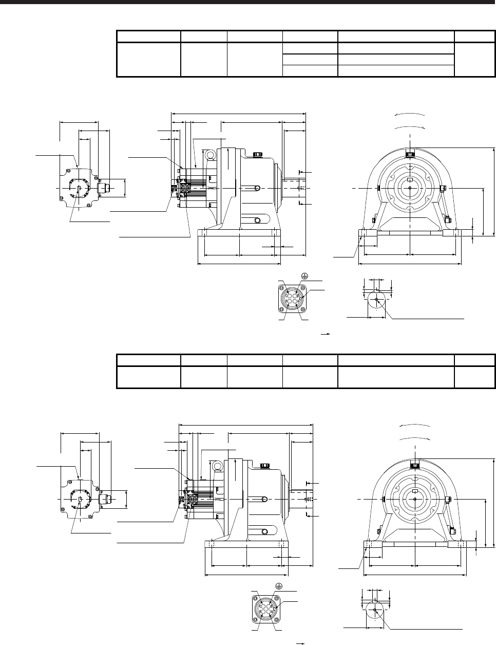
7. HG-SR SERIES
7 - 54
Model Output [kW] Reducer model Reduction ratio Moment of inertia J [× 10-4 kg•m2] Mass [kg]
HG-SR502G1H
HG-SR5024G1H 5.0
1/29 141
178
CHHM-6180 1/35 140
1/43 139
[Unit: mm]
U
W
V
Power supply connector
Motor flange direction
Key
176
M12 Screw hole depth 24
616
Motor plate
Caution plate
13
24.863.7
Shaft section view AA
38.5
14
9
(Side view of motor only)
□176
140.9
Caution plate
82
Caution plate
Motor plate
Top
50.9
Top
4-φ22
470
210210
85
30
220
405
279 110
100
380
160 160 145
A
A
φ370
Encoder connector
CMV1-R10P
Power supply connector
MS3102A22-22P
BC41151*
(PE) 22
30
φ80h6
Bottom
Bottom
For reverse rotation command
For forward rotation command
Rotation direction
Model Output [kW] Reducer model Reduction ratio Moment of inertia J [× 10-4 kg•m2] Mass [kg]
HG-SR502G1H
HG-SR5024G1H 5.0 CHHM-6185 1/59 138 178
[Unit: mm]
U
W
V
Power supply connector
Motor flange direction
Key
176
M12 Screw hole depth 24
616
Caution plate
13
24.863.7
Shaft section view AA
38.5
22
14
9
φ80h6
(Side view of motor only)
□176
140.9
Caution plate
82
Caution plate
Motor plate
Top
50.9
Top
4-φ22 470
210210
85
30
220
405
279 110
100
380
160 160 145
A
A
φ370
Encoder connector
CMV1-R10P
Power supply connector
MS3102A22-22P
BC41152*
(PE)
30
Bottom
Bottom
Motor plate
For reverse rotation command
For forward rotation command
Rotation direction
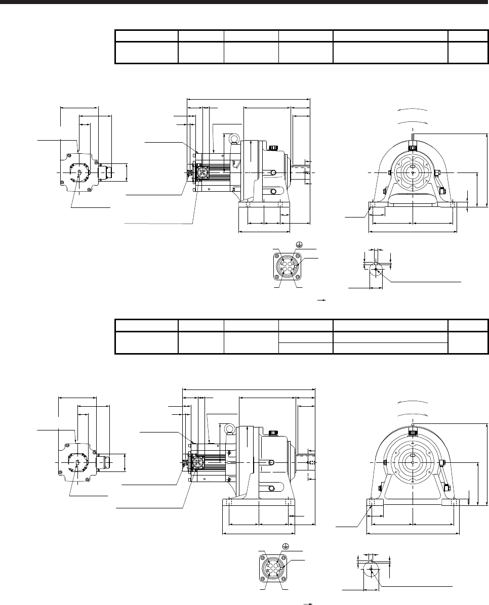
7. HG-SR SERIES
7 - 55
Model Output [kW] Reducer model Reduction ratio Moment of inertia J [× 10-4 kg•m2] Mass [kg]
HG-SR702G1H
HG-SR7024G1H 7.0 CHHM-6165 1/6 177 108
[Unit: mm]
U
W
V
Power supply connector
Motor flange direction
Key
571.5
□176
149.1
Caution plate
82
Caution plate
Motor plate
Motor plate
Caution plate
13
32
71.7
Top
50.9
38.5
Top
Shaft section view AA
18
7
11
M10 Screw hole depth 18
(Side view of motor only)
75
410
185 185
25
160
341
4-φ18
218 90
80
238
75 13975
44
A
A
φ300
181
Encoder connector
CMV1-R10P
Power supply connector
MS3102A32-17P
BC41153*
(PE)
φ60h6
Bottom
Bottom
For reverse rotation command
For forward rotation command
Rotation direction
Model Output [kW] Reducer model Reduction ratio Moment of inertia J [× 10-4 kg•m2] Mass [kg]
HG-SR702G1H
HG-SR7024G1H 7.0 CHHM-6170 1/11 190
148
1/17 182
[Unit: mm]
U
W
V
Power supply connector
Motor flange direction
Key
616
Motor plate
Caution plate
13
32
71.7
38.5
7.5
20
12
M12 Screw hole depth 24
φ70h6
Shaft section view AA
181
(Side view of motor only)
□176
149.1
Caution plate
82
Caution plate
Motor plate
Top
50.9
Top
430
190 190
80
200
30
381
4-φ22
A
A
90
80
335
125137.5 137.5
30
262
φ340
Encoder connector
CMV1-R10P
Power supply connector
MS3102A32-17P
BC41154*
(PE)
Bottom
Bottom
For reverse rotation command
For forward rotation command
Rotation direction
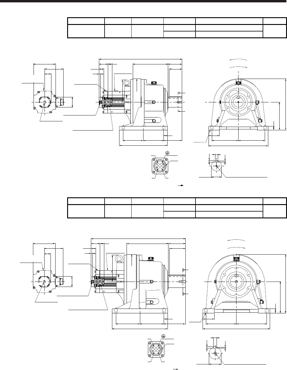
7. HG-SR SERIES
7 - 56
Model Output [kW] Reducer model Reduction ratio Moment of inertia J [× 10-4 kg•m2] Mass [kg]
HG-SR702G1H
HG-SR7024G1H 7.0 CHHM-6180 1/29 192
185
1/35 192
[Unit: mm]
U
W
V
Power supply connector
Motor flange direction
Key
656
Motor plate
Caution plate
13
32
71.7
38.5
176
M12 Screw hole depth 24
Shaft section view AA
22
14
9
φ80h6
(Side view of motor only)
□176
149.1
Caution plate
82
Caution plate
Motor plate
Top
50.9
Top
4-φ22
470
210210
85
30
220
405
279 110
100
380
160 160
30
145
A
A
φ370
Encoder connector
CMV1-R10P
Power supply connector
MS3102A32-17P
BC41155*
(PE)
Bottom
Bottom
For reverse rotation command
For forward rotation command
Rotation direction
Model Output [kW] Reducer model Reduction ratio Moment of inertia J [× 10-4 kg•m2] Mass [kg]
HG-SR702G1H
HG-SR7024G1H 7.0 CHHM-6180 1/43 267
256
1/59 266
[Unit: mm]
U
W
V
Power supply connector
Motor flange direction
Key
210
9
14
25
φ95h6 M20 Screw hole depth 34
747
Motor plate
Caution plate
13
3271.7
Shaft section view AA
38.5
(Side view of motor only)
□176
149.1
Caution plate
82
Caution plate
Motor plate
Top
50.9
Top
530
240 240
90
250
35
4-φ26
465
135330
170
440
190 190
30
125
A
A
φ430
Encoder connector
CMV1-R10P
Power supply connector
MS3102A32-17P
BC41156*
(PE)
For reverse rotation command
For forward rotation command
Rotation direction
Bottom
Bottom
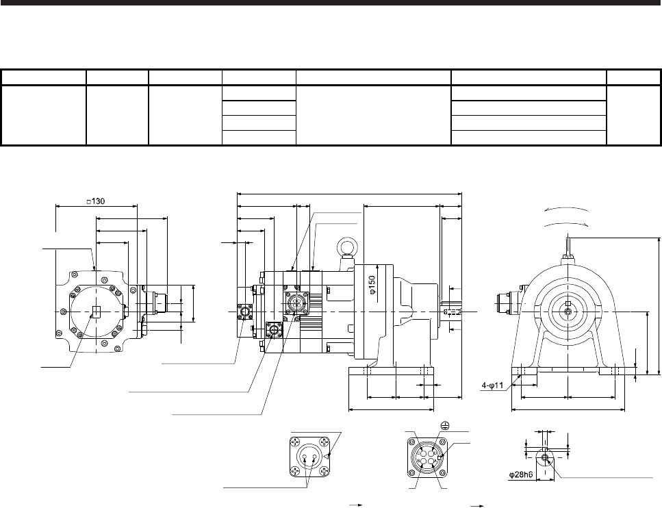
7. HG-SR SERIES
7 - 57
7.7.6 For general industrial machine with a reducer (foot-mounting/with an electromagnetic brake)
Model Output [kW] Reducer model Reduction ratio Brake static friction torque [N•m] Moment of inertia J [× 10-4 kg•m2] Mass [kg]
HG-SR52BG1H
HG-SR524BG1H 0.5
1/6
8.5
10.3
22
CNHM-6100 1/11 9.85
1/17 9.73
1/29 9.67
[Unit: mm]
29
95.2
Electromagnetic brake connector
CMV1-R2P
Power supply connector
MS3102A18-10P
79.9
Encoder connector
CMV1-R10P
59
13
58
13.5
112.5
50.9
Motor plate
43.5
20.9
TopBottom
U
W
V
Power supply connector
Motor flange direction
Key
Electromagnetic brake
Electromagnetic brake connector
Motor flange direction
Main key
position mark
Caution plate
(Side view of motor only)
12
100
219
121 35
32
A
A
357.5
Shaft section view AA
4
7
8
M8 Screw hole depth 20
BC41205*
Bottom Top
Caution
plate
15
45 45
135
60
40
75 75
180
For reverse rotation command
For forward rotation command
Rotation direction
(PE)
Caution plate
Motor plate
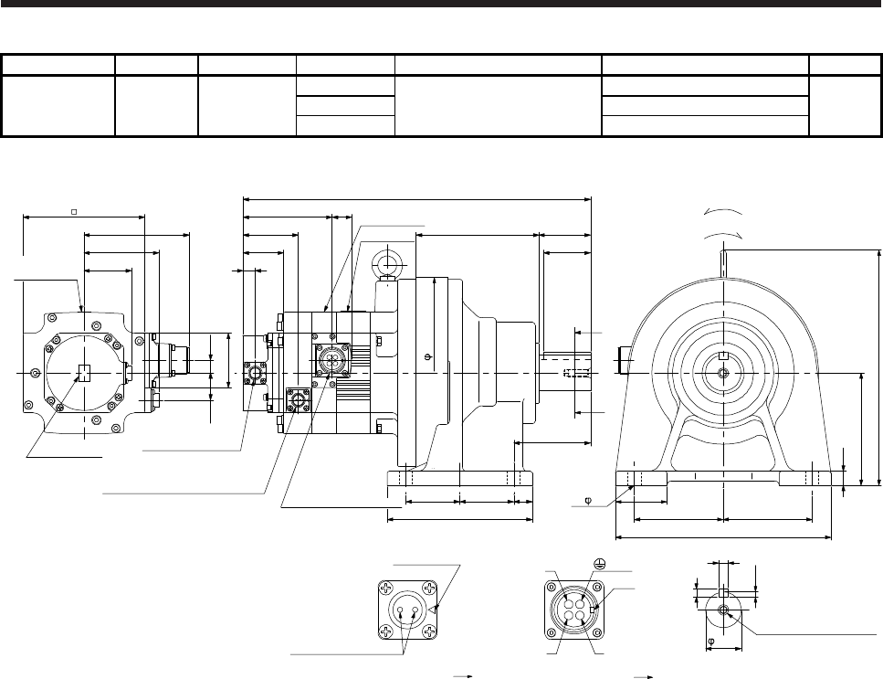
7. HG-SR SERIES
7 - 58
Model Output [kW] Reducer model Reduction ratio Brake static friction torque [N•m] Moment of inertia J [× 10-4 kg•m2] Mass [kg]
HG-SR52BG1H
HG-SR524BG1H 0.5
1/35
8.5
10.5
30
CNHM-6120 1/43 10.4
1/59 10.4
[Unit: mm]
Shaft section view AA
38h6
55131
8
5
10
For reverse rotation command
For forward rotation command
Rotation direction
50
A
A
M8 Screw hole depth 20
29
95.2
Electromagnetic brake connector
CMV1-R2P
MS3102A18-10P
79.9
Encoder connector
CMV1-R10P
59
13
58
13.5
130
112.5
50.9
(Side view of motor only)
Caution plate
Motor plate
371
43.5
20.9
Bottom Top
Top
Bottom
U
W
V
Power supply connector
Motor flange direction
Key
Electromagnetic brake
Electromagnetic brake connector
Motor flange direction
Main key
position mark
252
120
95
230
95
55
4- 14
15
155
57.5
204
57.5 20
82
Caution plate
(PE)
Power supply connector
Caution plate
Motor plate
AB
CD
BC41206*
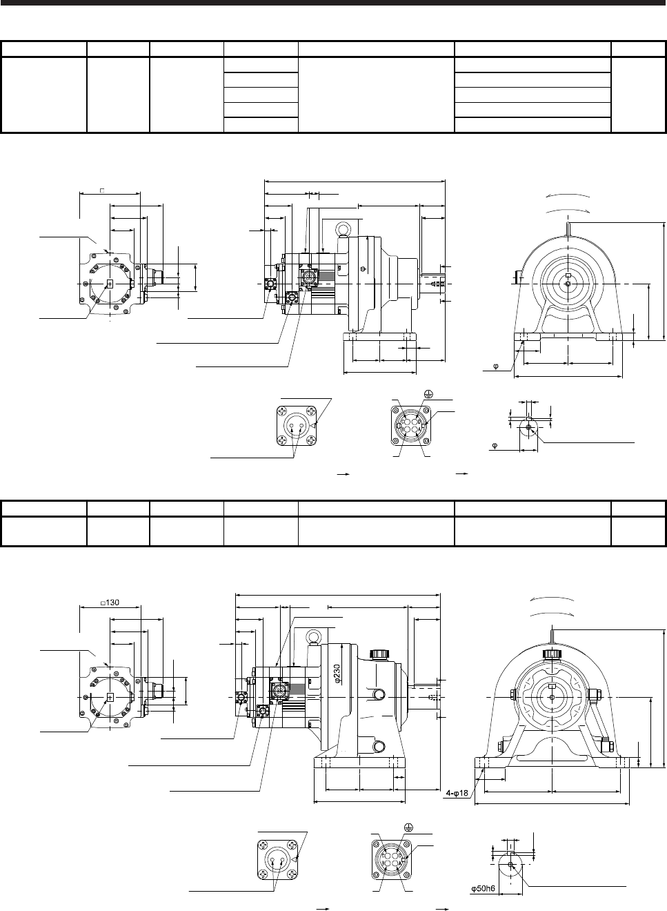
7. HG-SR SERIES
7 - 59
Model Output [kW] Reducer model Reduction ratio Brake static friction torque [N•m] Moment of inertia J [× 10-4 kg•m2] Mass [kg]
HG-SR102BG1H
HG-SR1024BG1H 1.0
1/6
8.5
17.0
33
1/11 15.5
CNHM-6120 1/17 15.1
1/29 14.8
1/35 14.8
[Unit: mm]
Caution plate
Motor plate
29
95.2
Electromagnetic brake connector
CMV1-R2P
79.9
59
13
58
13.5
130
112.5
50.9
Caution plate
385
43.5
20.9
Bottom Top
Top
Bottom
Motor plate
Encoder connector
CMV1-R10P
Power supply connector
MS3102A18-10P
U
W
V
Power supply connector
Motor flange direction
Key
Electromagnetic brake
Electromagnetic brake connector
Motor flange direction
Main key
position mark
(Side view of motor only)
5
8
10
38h6
Shaft section view AA
M8 Screw hole depth 20
20
57.5 57.5 82
155
55
95 95
230
131 55
50
A
A
4- 14
15
120
252
204
Caution plate
For reverse rotation command
For forward rotation command
Rotation direction
BC41207*
(PE)
Model Output [kW] Reducer model Reduction ratio Brake static friction torque [N•m] Moment of inertia J [× 10-4 kg•m2] Mass [kg]
HG-SR102BG1H
HG-SR1024BG1H 1.0 CHHM-6130 1/43 8.5 16.0 52
[Unit: mm]
29
95.2
Electromagnetic brake connector
CMV1-R2P
79.9
59
13
58
13.5
112.5
50.9
Caution plate
437.5
43.5
20.9
Bottom Top
TopBottom
Encoder connector
CMV1-R10P
Power supply connector
MS3102A18-10P
U
W
V
Power supply connector
Motor flange direction
Key
Electromagnetic brake
Electromagnetic brake connector
Motor flange direction
Main key
position mark
(Side view of motor only)
5.5
9
14
Shaft section view AA
M10 Screw hole depth 18
170 70
56
22
150
295
65
145 145
330
25
72.5 72.5
195
100
A
A
Motor plate
Caution plate
For reverse rotation command
For forward rotation command
Rotation direction
BC41208*
(PE)
Caution plate
Motor plate
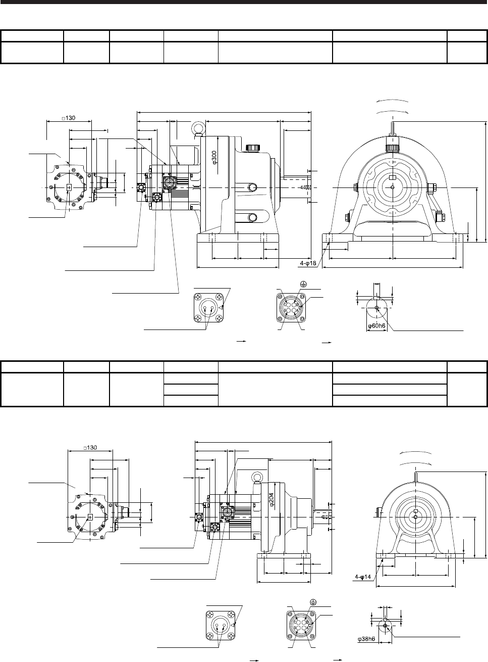
7. HG-SR SERIES
7 - 60
Model Output [kW] Reducer model Reduction ratio Brake static friction torque [N•m] Moment of inertia J [× 10-4 kg•m2] Mass [kg]
HG-SR102BG1H
HG-SR1024BG1H 1.0 CHHM-6160 1/59 8.5 21.3 88
[Unit: mm]
Caution plate
Motor plate
29
95.2
Electromagnetic brake connector
CMV1-R2P
79.9
59
13
58
13.5
112.5
50.9
Caution plate
508
43.5
20.9
Bottom Top
TopBottom
Motor plate
Encoder connector
CMV1-R10P
Power supply connector
MS3102A18-10P
25
160
352
75
185 185
410
44
75 75 139
238
218 90
80
A
A
7
M10 Screw hole depth 18
11
18
Shaft section view AA
U
W
V
Power supply connector
Motor flange direction
Key
Electromagnetic brake
Electromagnetic brake connector
Motor flange direction
Main key
position mark
(Side view of motor only)
For reverse rotation command
For forward rotation command
Rotation direction
BC41209*
(PE)
Caution plate
Model Output [kW] Reducer model Reduction ratio Brake static friction torque [N•m] Moment of inertia J [× 10-4 kg•m2] Mass [kg]
HG-SR152BG1H
HG-SR1524BG1H 1.5
1/6
8.5
21.4
34
CNHM-6120 1/11 19.9
1/17 19.5
[Unit: mm]
Caution plate
Motor plate
29
95.2
Electromagnetic brake connector
CMV1-R2P
79.9
59
13
58
13.5
112.5
50.9
Caution plate
399
43.5
20.9
Bottom Top
Top
Bottom
Motor plate
Encoder connector
CMV1-R10P
Power supply connector
MS3102A18-10P
U
W
V
Power supply connector
Motor flange direction
Key
Electromagnetic brake
Electromagnetic brake connector
Motor flange direction
Main key
position mark
(Side view of motor only)
5
8
10
Shaft section view AA
M8 Screw hole depth 20
20
57.5 57.5 82
155
55
95 95
230
131 55
50
A
A
15
120
252
Caution plate
For reverse rotation command
For forward rotation command
Rotation direction
BC41210*
(PE)
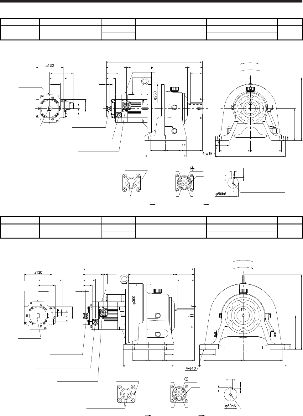
7. HG-SR SERIES
7 - 61
Model Output [kW] Reducer model Reduction ratio Brake static friction torque [N•m] Moment of inertia J [× 10-4 kg•m2] Mass [kg]
HG-SR152BG1H
HG-SR1524BG1H 1.5 CHHM-6130 1/29 8.5 20.6 53
1/35 20.5
[Unit: mm]
Caution plate
Motor plate
29
95.2
Electromagnetic brake connector
CMV1-R2P
79.9
59
13
58
13.5
112.5
50.9
Caution plate
451.5
43.5
20.9
Bottom Top
TopBottom
Motor plate
U
W
V
Power supply connector
Motor flange direction
Key
Electromagnetic brake
Electromagnetic brake connector
Motor flange direction
Main key
position mark
(Side view of motor only)
5.5
9
14
Shaft section view AA
M10 Screw hole depth 18
170 70
56
22
150
295
65
145 145
330
25
72.5 72.5
195
100
A
A
Caution plate
Encoder connector
CMV1-R10P
Power supply connector
MS3102A18-10P
For reverse rotation command
For forward rotation command
Rotation direction
BC41211*
(PE)
Model Output [kW] Reducer model Reduction ratio Brake static friction torque [N•m] Moment of inertia J [× 10-4 kg•m2] Mass [kg]
HG-SR152BG1H
HG-SR1524BG1H 1.5 CHHM-6160 1/43 8.5 25.8 89
1/59 25.7
[Unit: mm]
Caution plate
Motor plate
29
95.2
Electromagnetic brake connector
CMV1-R2P
79.9
59
13
58
13.5
112.5
50.9
Caution plate
522
43.5
20.9
Bottom Top
Top
Bottom
25
160
352
75
185 185
410
7
M10 Screw hole depth 18
11
18
Shaft section view AA
U
W
V
Power supply connector
Motor flange direction
Key
Electromagnetic brake
Electromagnetic brake connector
Motor flange direction
Main key
position mark
(Side view of motor only)
218 90
80
44
75 75 139
238
A
A
Motor plate
Caution plate
Encoder connector
CMV1-R10P
Power supply connector
MS3102A18-10P
For reverse rotation command
For forward rotation command
Rotation direction
BC41212*
(PE)
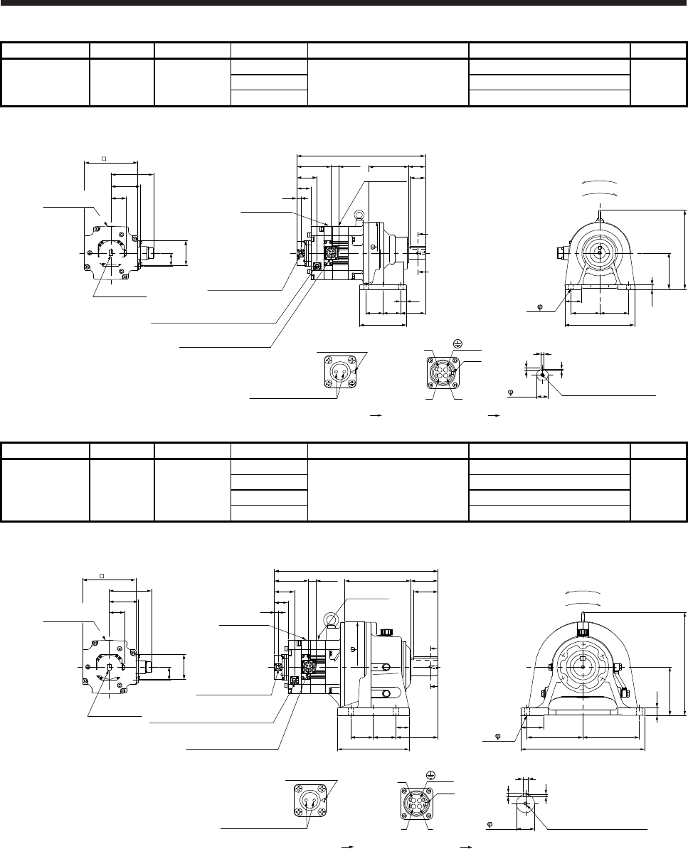
7. HG-SR SERIES
7 - 62
Model Output [kW] Reducer model Reduction ratio Brake static friction torque [N•m] Moment of inertia J [× 10-4 kg•m2] Mass [kg]
HG-SR202BG1H
HG-SR2024BG1H 2.0
1/6
44
59.4
43
CNHM-6120 1/11 57.8
1/17 57.5
[Unit: mm]
U
W
V
Power supply connector
Motor flange direction
Key
Electromagnetic brake
Electromagnetic brake connector
Motor flange direction
Main key
position mark
Shaft section view AA
Motor plate
Caution plate
13
24.8
113.2
66.5
45.5
57.5 57.5
20
82
155
A
A
131
50
55
424
204
Power supply connector
MS3102A22-22P
Electromagnetic brake connector
CMV1-R2P
Encoder connector
CMV1-R10P
4- 14 95
55
230
95
15
262
120
176
96.9
140.9
Caution plate
44
Caution plate
Motor plate
TopBottom
50.9
TopBottom
82
(Side view of motor only)
5
10
8
38h6 M8 Screw hole depth 20
For reverse rotation command
For forward rotation command
Rotation direction
BC41213*
(PE)
Model Output [kW] Reducer model Reduction ratio Brake static friction torque [N•m] Moment of inertia J [× 10-4 kg•m2] Mass [kg]
HG-SR202BG1H
HG-SR2024BG1H 2.0
1/29
44
64.2
98
CHHM-6165 1/35 63.9
1/43 63.7
1/59 63.6
[Unit: mm]
U
W
V
Power supply connector
Motor flange direction
Key
Electromagnetic brake
Electromagnetic brake connector
Motor flange direction
Main key
position mark
M10 Screw hole depth 18
Shaft section view AA
18
11
7
176
96.9
140.9
Caution plate
44
Caution plate
13
24.8113.2
66.5
Power supply connector
MS3102A22-22P
Electromagnetic brake connector
CMV1-R2P
Encoder connector
CMV1-R10P
TopBottom
50.9 45.5
TopBottom
82
4- 18 185
75
410
185
25
341
160
75 75
44
139
238
A
A
218
80
90
541
(Side view of motor only)
Caution plate
Motor plate
300
For reverse rotation command
For forward rotation command
Rotation direction
BC41214*
(PE)
60h6
Motor plate
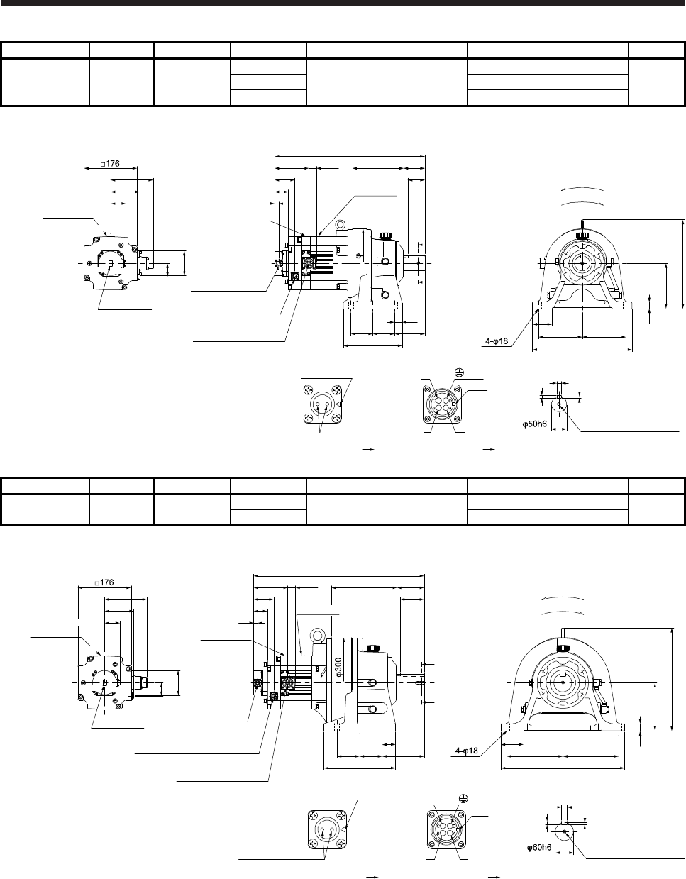
7. HG-SR SERIES
7 - 63
Model Output [kW] Reducer model Reduction ratio Brake static friction torque [N•m] Moment of inertia J [× 10-4 kg•m2] Mass [kg]
HG-SR352BG1H
HG-SR3524BG1H 3.5
1/6
44
96.5
67
CHHM-6135 1/11 92.2
1/17 90.9
[Unit: mm]
BC41215*
U
W
V
Power supply connector
Motor flange direction
Key
Electromagnetic brake
Electromagnetic brake connector
Motor flange direction
Main key
position mark
96.9
140.9
Caution plate
44
Caution plate
Motor plate
Motor plate
Caution plate
13
24.8113.2
66.5
Power supply connector
MS3102A22-22P
Electromagnetic brake connector
CMV1-R2P
Encoder connector
CMV1-R10P
Top
Bottom
Shaft section view AA
50.9
45.5
TopBottom
82
M10 Screw hole depth 18
14
9
5.5
72.5 72.5
25
195 145
65
330
145
22
295
150
A
(Side view of motor only)
A
100
170
56
70
497.5
For reverse rotation command
For forward rotation command
Rotation direction
(PE)
230
Model Output [kW] Reducer model Reduction ratio Brake static friction torque [N•m] Moment of inertia J [× 10-4 kg•m2] Mass [kg]
HG-SR352BG1H
HG-SR3524BG1H 3.5 CHHM-6165 1/29 44 96.0 103
1/35 95.7
[Unit: mm]
BC41216*
U
W
V
Power supply connector
Motor flange direction
Key
Electromagnetic brake
Electromagnetic brake connector
Motor flange direction
Main key
position mark
M10 Screw hole depth 18
96.9
140.9
Caution plate
44
Caution plate
Motor plate
Motor plate
Caution plate
13
24.8113.2
66.5
Power supply connector
MS3102A22-22P
Electromagnetic brake connector
CMV1-R2P
Encoder connector
CMV1-R10P
TopBottom
Shaft section view AA
50.9
45.5
18
11
7
TopBottom
82
185
75
410
185
25
341
160
565
(Side view of motor only)
75 75
44
139
238
A
A
218
80
90 For reverse rotation command
For forward rotation command
Rotation direction
(PE)
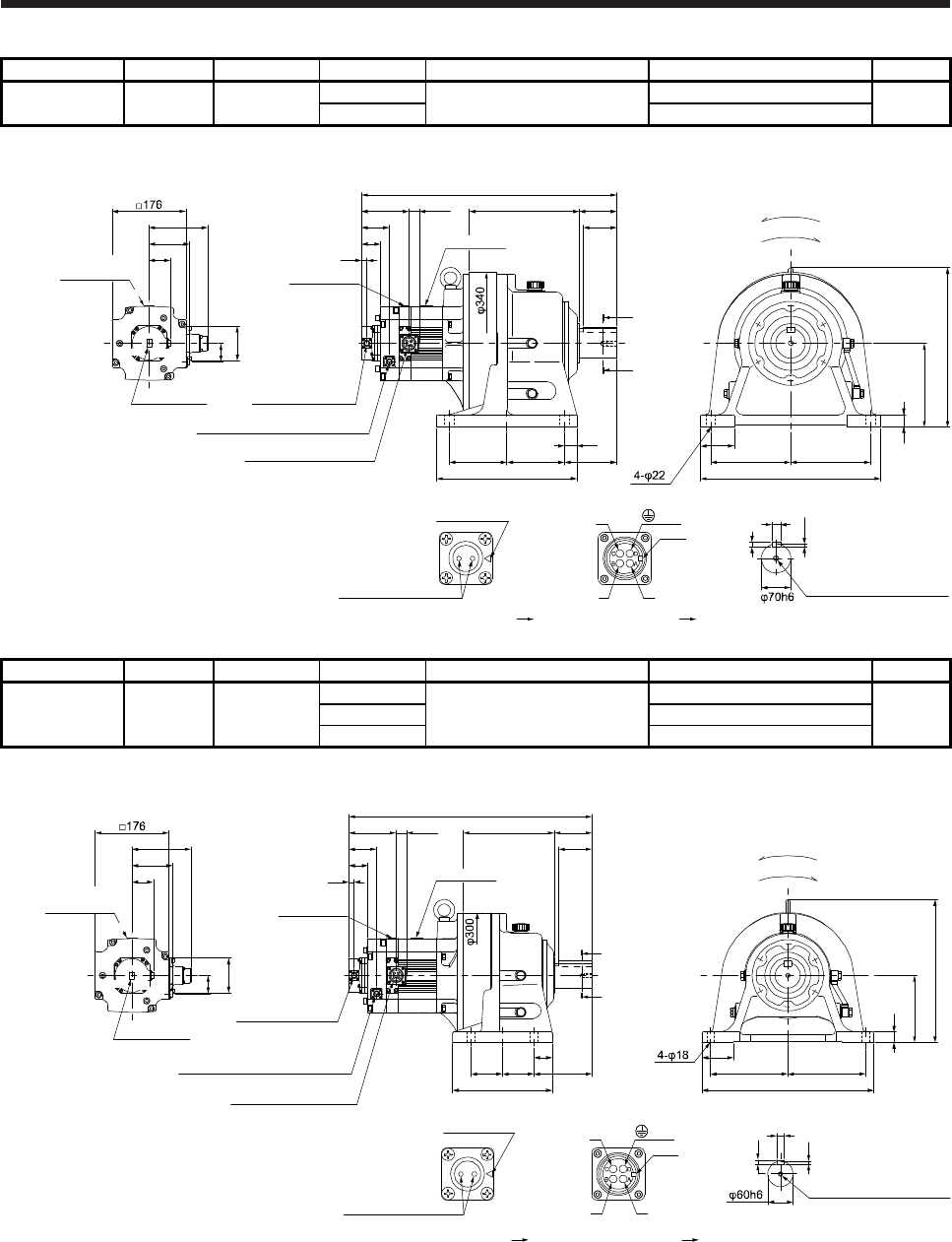
7. HG-SR SERIES
7 - 64
Model Output [kW] Reducer model Reduction ratio Brake static friction torque [N•m] Moment of inertia J [× 10-4 kg•m2] Mass [kg]
HG-SR352BG1H
HG-SR3524BG1H 3.5 CHHM-6175 1/43 44 114 143
1/59 113
[Unit: mm]
BC41217*
U
W
V
Power supply connector
Motor flange direction
Key
Electromagnetic brake
Electromagnetic brake connector
Motor flange direction
Main key
position mark
M12 Screw hole depth 24
96.9
140.9
Caution plate
44
30
Caution plate
Motor plate
Motor plate
Caution plate
13
24.8113.2
66.5
Power supply connector
MS3102A22-22P
Electromagnetic brake connector
CMV1-R2P
Encoder connector
CMV1-R10P
TopBottom
Shaft section view AA
50.9
45.5
20
12
7.5
TopBottom
A
A
262
80
137.5 137.5
30
125
90
609.5
335
190
80
430
190
381
200
82
(Side view of motor only)
For reverse rotation command
For forward rotation command
Rotation direction
(PE)
Model Output [kW] Reducer model Reduction ratio Brake static friction torque [N•m] Moment of inertia J [× 10-4 kg•m2] Mass [kg]
HG-SR502BG1H
HG-SR5024BG1H 5.0
1/6
44
135
107
CHHM-6165 1/11 123
1/17 119
[Unit: mm]
BC41218*
U
W
V
Power supply connector
Motor flange direction
Key
Electromagnetic brake
Electromagnetic brake connector
Motor flange direction
Main key
position mark
96.9
140.9
Caution plate
44
82
Motor plate
Caution plate
13
24.8113.2
66.5
TopBottom
50.9
45.5
TopBottom
581
18
7
11
Shaft section view AA
M10 Screw hole depth 18
(Side view of motor only) 75
410
185 185
25
160
341
218 90
80
238
75 13975
44
A
A
For reverse rotation command
For forward rotation command
Rotation direction
Encoder connector
CMV1-R10P
Electromagnetic brake connector
CMV1-R2P
Power supply connector
MS3102A22-22P
(PE)
Caution plate
Motor plate
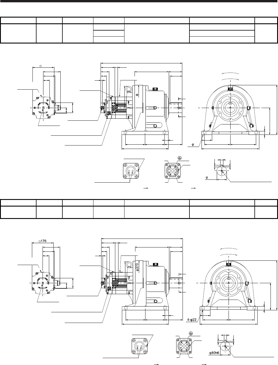
7. HG-SR SERIES
7 - 65
Model Output [kW] Reducer model Reduction ratio Brake static friction torque [N•m] Moment of inertia J [× 10-4 kg•m2] Mass [kg]
HG-SR502BG1H
HG-SR5024BG1H 5.0
1/29
44
150
184
CHHM-6180 1/35 150
1/43 149
[Unit: mm]
BC41219*
U
W
V
Power supply connector
Motor flange direction
Key
Electromagnetic brake
Electromagnetic brake connector
Motor flange direction
Main key
position mark
176
M12 Screw hole depth 24
665.5
176
96.9
140.9
Caution plate
44
82
Caution plate
Motor plate Caution plate
13
24.8113.2
66.5
TopBottom
Shaft section view AA
50.9
45.5
22
14
9
80h6
TopBottom
(Side view of motor only)
4- 22 470
210210
85
30
220
405
279 110
100
380
160 160
30
145
A
A
370
For reverse rotation command
For forward rotation command
Rotation direction
Encoder connector
CMV1-R10P
Electromagnetic brake connector
CMV1-R2P
Power supply connector
MS3102A22-22P
(PE)
Motor plate
Model Output [kW] Reducer model Reduction ratio Brake static friction torque [N•m] Moment of inertia J [× 10-4 kg•m2] Mass [kg]
HG-SR502BG1H
HG-SR5024BG1H 5.0 CHHM-6185 1/59 44 147 184
[Unit: mm]
BC41220*
U
W
V
Power supply connector
Motor flange direction
Key
Electromagnetic brake
Electromagnetic brake connector
Motor flange direction
Main key
position mark
176
M12 Screw hole depth 24
665.5
96.9
140.9
Caution plate
44
82
Caution plate
Motor plate
Motor plate
Caution plate
13
24.8113.2
66.5
TopBottom
Shaft section viewAA
50.9
45.5
22
14
9
TopBottom
(Side view of motor only)
470
210210
85
30
220
405
279 110
100
380
160 160
30
145
A
A
For reverse rotation command
For forward rotation command
Rotation direction
Encoder connector
CMV1-R10P
Electromagnetic brake connector
CMV1-R2P
Power supply connector
MS3102A22-22P
(PE)
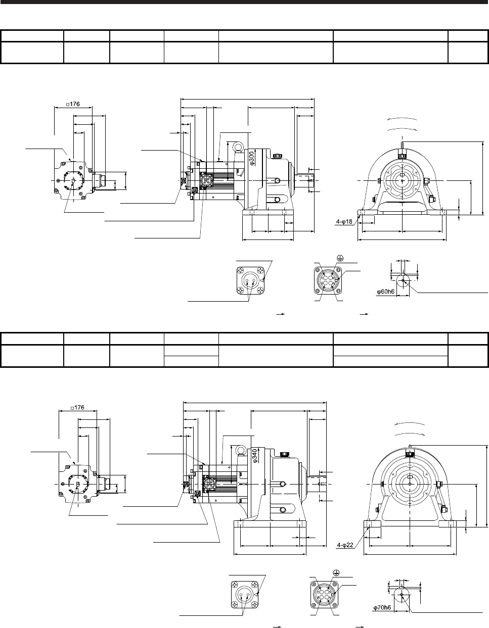
7. HG-SR SERIES
7 - 66
Model Output [kW] Reducer model Reduction ratio Brake static friction torque [N•m] Moment of inertia J [× 10-4 kg•m2] Mass [kg]
HG-SR702BG1H
HG-SR7024BG1H 7.0 CHHM-6165 1/6 44 187 114
[Unit: mm]
BC41221*
U
W
V
Power supply connector
Motor flange direction
Key
Electromagnetic brake
Electromagnetic brake connector
Motor flange direction
Main key
position mark
621
96.9
149.1
Caution plate
44
82
Caution plate
Motor plate Caution plate
13
32121.2
66.5
TopBottom
50.9
45.5
TopBottom
Shaft section view AA
18
7
11
M10 Screw hole depth 18
(Side view of motor only) 75
410
185 185
25
160
341
218 90
80
238
75 13975
44
A
A
181
For reverse rotation command
For forward rotation command
Rotation direction
Encoder connector
CMV1-R10P
Electromagnetic brake connector
CMV1-R2P
Power supply connector
MS3102A32-17P
(PE)
Motor plate
Model Output [kW] Reducer model Reduction ratio Brake static friction torque [N•m] Moment of inertia J [× 10-4 kg•m2] Mass [kg]
HG-SR702BG1H
HG-SR7024BG1H 7.0 CHHM-6170 1/11 44 199 154
1/17 192
[Unit: mm]
BC41222*
U
W
V
Power supply connector
Motor flange direction
Key
Electromagnetic brake
Electromagnetic brake connector
Motor flange direction
Main key
position mark
665.5
96.9
149.1
Caution plate
44
82
Motor plate
Caution plate
13
32121.2
66.5
TopBottom
50.9
45.5
TopBottom
7.5
20
12
M12 Screw hole depth 24
Shaft section view AA
181
(Side view of motor only)
430
190 190
80
200
30
381
A
A
90
80
335
125137.5 137.5
30
262
For reverse rotation command
For forward rotation command
Rotation direction
Encoder connector
CMV1-R10P
Electromagnetic brake connector
CMV1-R2P
Power supply connector
MS3102A32-17P
(PE)
Caution plate
Motor plate
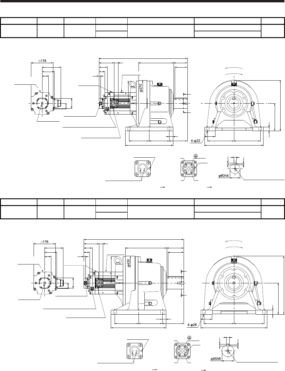
7. HG-SR SERIES
7 - 67
Model Output [kW] Reducer model Reduction ratio Brake static friction torque [N•m] Moment of inertia J [× 10-4 kg•m2] Mass [kg]
HG-SR702BG1H
HG-SR7024BG1H 7.0 CHHM-6180 1/29 44 202 191
1/35 201
[Unit: mm]
BC41223*
U
W
V
Power supply connector
Motor flange direction
Key
Electromagnetic brake
Electromagnetic brake connector
Motor flange direction
Main key
position mark
705.5
96.9
149.1
Caution plate
44
82
Caution plate
Motor plate
Motor plate
Caution plate
13
32121.2
66.5
TopBottom
50.9
45.5
TopBottom
176
M12 Screw hole depth 24
Shaft section view AA
22
14
9
(Side view of motor only)
470
210210
85
30
220
405
279 110
100
380
160 160
30
145
A
A
For reverse rotation command
For forward rotation command
Rotation direction
Encoder connector
CMV1-R10P
Electromagnetic brake connector
CMV1-R2P
Power supply connector
MS3102A32-17P
(PE)
Model Output [kW] Reducer model Reduction ratio Brake static friction torque [N•m] Moment of inertia J [× 10-4 kg•m2] Mass [kg]
HG-SR702BG1H
HG-SR7024BG1H 7.0 CHHM-6195 1/43 44 277 262
1/59 275
[Unit: mm]
BC41224*
U
W
V
Power supply connector
Motor flange direction
Key
Main key
position mark
210
9
14
25
M20 Screw hole depth 34
796.5
96.9
149.1
Caution plate
44
82
Caution plate
Motor plate
Motor plate
Caution plate
13
32121.2
66.5
TopBottom
Shaft section view AA
50.9
45.5
TopBottom
(Side view of motor only)
530
240 240
90
250
35
465
135330
170
440
190 190
30
125
A
A
For reverse rotation command
For forward rotation command
Rotation direction
(PE)
Electromagnetic brake
Electromagnetic brake connector
Motor flange direction
Encoder connector
CMV1-R10P
Electromagnetic brake connector
CMV1-R2P
Power supply connector
MS3102A32-17P
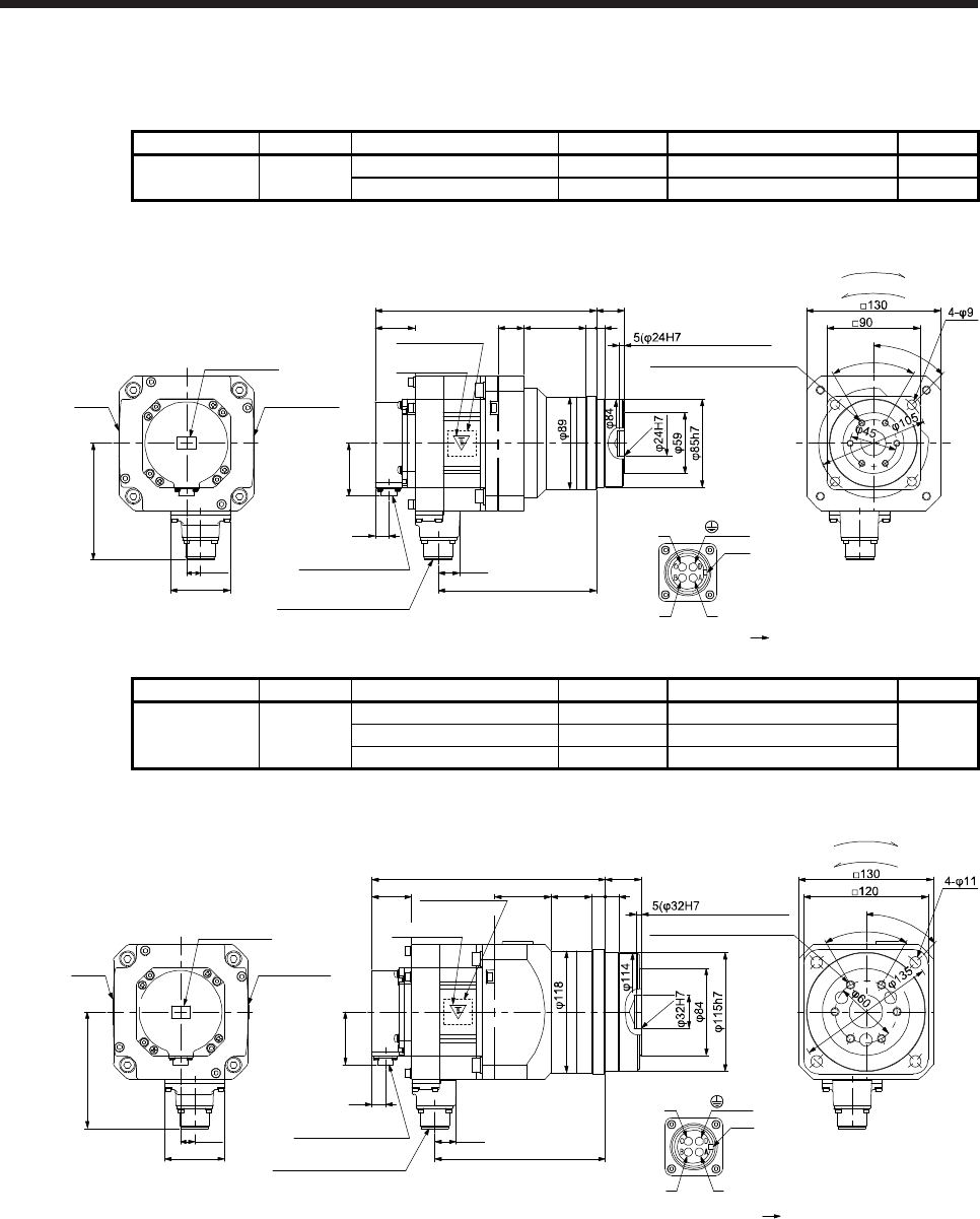
7. HG-SR SERIES
7 - 68
7.7.7 With flange-output type reducer for high precision applications, flange mounting (without an
electromagnetic brake)
Model Output [kW] Reducer model Reduction ratio Moment of inertia J [× 10-4 kg•m2] Mass [kg]
HG-SR52G5
HG-SR524G5 0.5 HPG-20A-05-F0KSAWS-S 1/5 7.91 7.6
HPG-20A-11-F0KSAXS-S 1/11 7.82 7.8
[Unit: mm]
213.5
20.9
152.8
Bottom
Top
U
W
V
Power supply connector
Motor flange direction
Key
25 60 10 8
effective range)
C0.5
45°
6-M6 Screw hole depth 10
38.2
Motor plate
(Opposite side)
50.9
13
Encoder connector
CMV1-R10P
Power supply connector
MS3102A18-10P
Motor
plate
Caution plate
Caution plate
Caution plate
Bottom
Top
Bottom
Top Top
Bottom
58
13.5
112.5
For reverse rotation command
For forward rotation command
Rotation direction
60°
BC41157*
(PE)
27+0.4
- 0.5
Model Output [kW] Reducer model Reduction ratio Moment of inertia J [× 10-4 kg•m2] Mass [kg]
HG-SR52G5
HG-SR524G5 0.5
HPG-32A-21-F0MCSYS-S 1/21 10.2
12
HPG-32A-33-F0MCSZS-S 1/33 9.96
HPG-32A-45-F0MCSZS-S 1/45 9.96
[Unit: mm]
225.5
20.9
164.8
Bottom
Top
U
W
V
Power supply connector
Motor flange direction
Key
54.5 39.5 13 13
effective range)
C0.5
45°
6-M8 Screw hole depth 12
38.2
Caution plate
Motor plate
(Opposite side)
50.9
13
Encoder connector
CMV1-R10P
Power supply connector
MS3102A18-10P
Motor
plate
Caution plate
Caution plate
Bottom
Top
Bottom
Top Top
Bottom
58
13.5
112.5
For reverse rotation command
For forward rotation command
Rotation direction
60°
BC41158*
35+0.4
- 0.5
(PE)
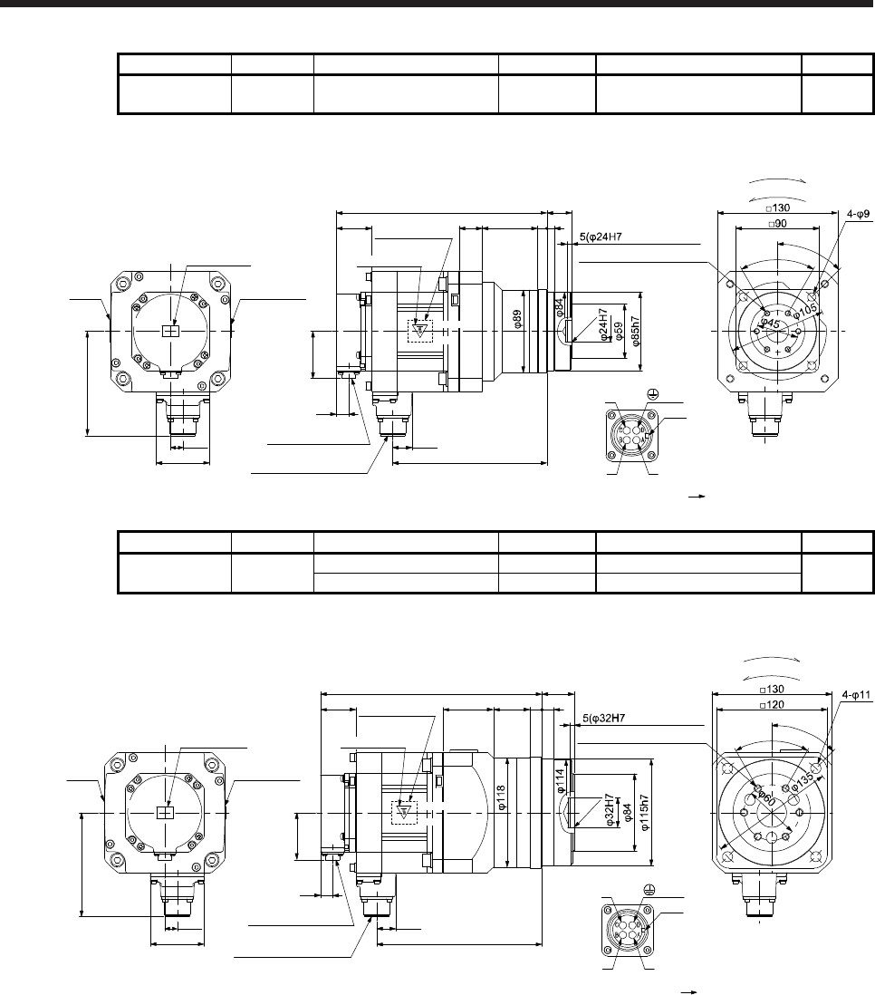
7. HG-SR SERIES
7 - 69
Model Output [kW] Reducer model Reduction ratio Moment of inertia J [× 10-4 kg•m2] Mass [kg]
HG-SR102G5
HG-SR1024G5 1.0 HPG-20A-05-F0KSAWS-S 1/5 12.3 9.0
[Unit: mm]
227.5
20.9
166.8
Bottom
Top
U
W
V
Power supply connector
Motor flange direction
Key
25 60 10 8
effective range)
C0.5
45°
6-M6 Screw hole depth 10
38.2 Motor plate
(Opposite side)
50.9
13
Encoder connector
CMV1-R10P
Power supply connector
MS3102A18-10P
Motor
plate
Caution plate
Caution plate
Bottom
Top
Bottom
Top Top
Bottom
58
13.5
112.5
Rotation direction
60°
BC41159*
(PE)
27+0.4
- 0.5
For reverse rotation command
For forward rotation command
Caution plate
Model Output [kW] Reducer model Reduction ratio Moment of inertia J [× 10-4 kg•m2] Mass [kg]
HG-SR102G5
HG-SR1024G5 1.0 HPG-32A-11-F0MCSPS-S 1/11 14.9 13
HPG-32A-21-F0MCSYS-S 1/21 14.5
[Unit: mm]
239.5
20.9
178.8
Bottom
Top
U
W
V
Power supply connector
Motor flange direction
Key
54.5 39.5 13 13
effective range)
45°
6-M8 Screw hole depth 12
38.2 Motor plate
(Opposite side)
50.9
13
Encoder connector
CMV1-R10P
Power supply connector
MS3102A18-10P
Motor
plate
Caution plate
Caution plate
Bottom
Top
Bottom
Top Top
Bottom
58
13.5
112.5
For reverse rotation command
For forward rotation command
Rotation direction
60°
BC41160*
(PE)
35+0.4
- 0.5
C0.5
Caution plate
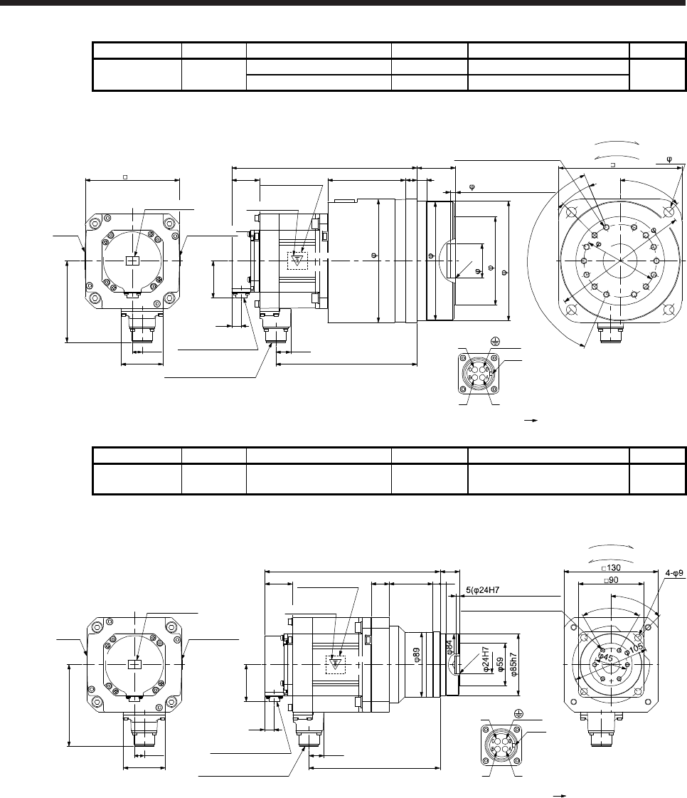
7. HG-SR SERIES
7 - 70
Model Output [kW] Reducer model Reduction ratio Moment of inertia J [× 10-4 kg•m2] Mass [kg]
HG-SR102G5
HG-SR1024G5 1.0 HPG-50A-33-F0AABC-S 1/33 16.3 23
HPG-50A-45-F0AABC-S 1/45 16.2
[Unit: mm]
255.5
20.9
194.8
Bottom
Top
U
W
V
Power supply connector
Motor flange direction
Key
38.2
Caution plate
Motor plate
(Opposite side)
50.9
13
Encoder connector
CMV1-R10P
Power supply connector
MS3102A18-10P
Motor
plate
Caution plate
Caution plate
Bottom
Top
Bottom
Top Top
Bottom
58
13.5
112.5
130
165h8
107 16
122
163
170
47H7
4- 14
170
For reverse rotation command
For forward rotation command
Rotation direction
13
45°
7( 47H7 effective range)
6×22.5°(=135°)
22.5°
C0.5
14-M8 Screw hole depth 12
BC41161*
(PE)
53+0.5
- 0.8
190
100
Model Output [kW] Reducer model Reduction ratio Moment of inertia J [× 10-4 kg•m2] Mass [kg]
HG-SR152G5
HG-SR1524G5 1.5 HPG-20A-05-F0KSAWS-S 1/5 16.7 11
[Unit: mm]
241.5
20.9
180.8
Bottom
Top
U
W
V
Power supply connector
Motor flange direction
Key
25 60 10 8
effective range)
C0.5
45°
6-M6 Screw hole depth 10
38.2 Motor plate
(Opposite side)
50.9
13
Encoder connector
CMV1-R10P
Power supply connector
MS3102A18-10P
Motor
plate
Caution plate
Caution plate
Bottom
Top
Bottom
Top Top
Bottom
58
13.5
112.5
For reverse rotation command
For forward rotation command
Rotation direction
60°
BC41162*
(PE)
27+0.4
- 0.5
Caution plate
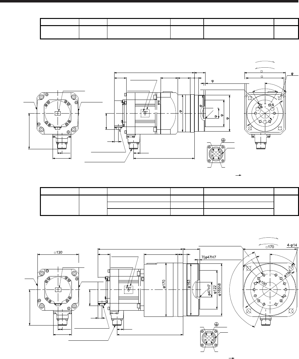
7. HG-SR SERIES
7 - 71
Model Output [kW] Reducer model Reduction ratio Moment of inertia J [× 10-4 kg•m2] Mass [kg]
HG-SR152G5
HG-SR1524G5 1.5 HPG-32A-11-F0MCSPS-S 1/11 19.3 14
[Unit: mm]
253.5
115h7
20.9
192.8
Bottom
Top
U
W
V
Power supply connector
Motor flange direction
Key
54.5 39.5 1313
84
114
118
120
45°
38.2
Caution plate
Motor plate
(Opposite side)
50.9
13
Encoder connector
CMV1-R10P
Power supply connector
MS3102A18-10P
Motor
plate
Caution plate
Caution plate
Bottom
Top
Bottom
Top Top
Bottom
58
13.5
112.5
130
For reverse rotation command
For forward rotation command
Rotation direction
4- 11
60°
BC41163*
(PE)
35+0.4
- 0.5
32H7
C0.5
135
60
5( 32H7 effective range)
6-M8 Screw hole depth 12
Model Output [kW] Reducer model Reduction ratio Moment of inertia J [× 10-4 kg•m2] Mass [kg]
HG-SR152G5
HG-SR1524G5 1.5
HPG-50A-21-F0AABC-S 1/21 21.7
24
HPG-50A-33-F0AABC-S 1/33 20.7
HPG-50A-45-F0AABC-S 1/45 20.6
[Unit: mm]
269.5
20.9
208.8
Bottom
Top
U
W
V
Power supply connector
Motor flange direction
Key
38.2
Caution plate
Motor plate
(Opposite side)
50.9
13
Encoder connector
CMV1-R10P
Power supply connector
MS3102A18-10P
Motor
plate
Bottom
Top
Bottom
Top Top
Bottom
58
13.5
112.5
107 16
For reverse rotation command
For forward rotation command
Rotation direction
13
45°
effective range)
6×22.5°(=135°)
22.5°
C0.5
14-M8 crew hole depth 12
BC41164*
(PE)
53+0.5
- 0.8
Caution plate
Caution plate
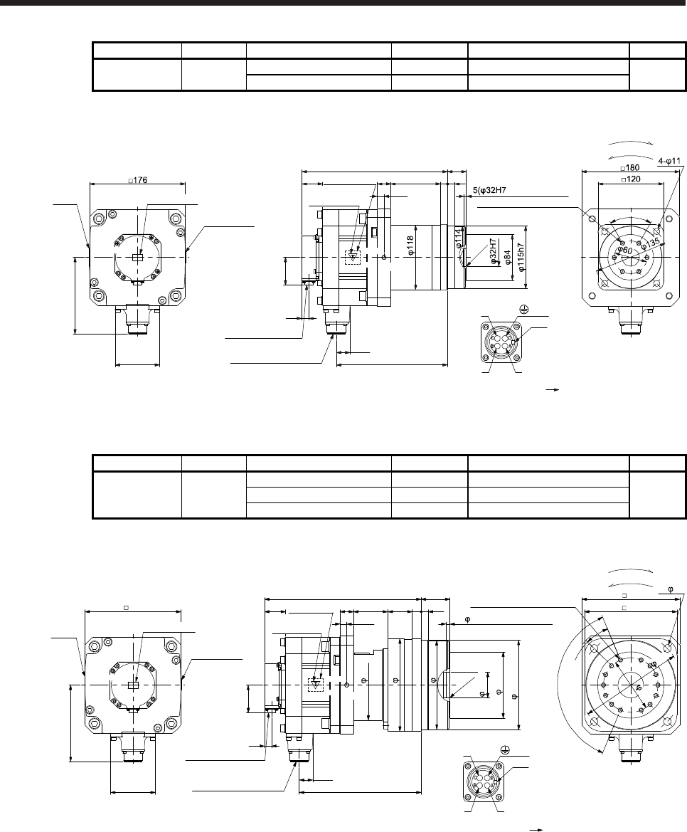
7. HG-SR SERIES
7 - 72
Model Output [kW] Reducer model Reduction ratio Moment of inertia J [× 10-4 kg•m2] Mass [kg]
HG-SR202G5
HG-SR2024G5 2.0 HPG-32A-05-F0PBZI-S 1/5 51.4 19
HPG-32A-11-F0PBZJ-S 1/11 51.2
[Unit: mm]
Bottom
Top Top
Bottom
267.5
Caution plate
Motor plate
(Opposite side)
24.8
203.8
Power supply connector
MS3102A22-22P
Bottom
Top
Bottom
Top
U
W
V
Power supply connector
Motor flange direction
Key
25 91 13
12.5
13
140.9
For reverse rotation command
For forward rotation command
Rotation direction
82
effective range)
C0.5
Motor
plate
Caution plate
60°
6-M8 Screw hole depth 12
38.5
50.9
13
Encoder connector
CMV1-R10P
BC41165*
(PE)
35+0.4
- 0.5
(Note)*
Caution plate
Note. * is a screw hole for eyebolt (M8).
Model Output [kW] Reducer model Reduction ratio Moment of inertia J [× 10-4 kg•m2] Mass [kg]
HG-SR202G5
HG-SR2024G5 2.0
HPG-50A-21-F0BBDF-S 1/21 53.2
29
HPG-50A-33-F0BBDF-S 1/33 52.2
HPG-50A-45-F0BBDF-S 1/45 52.2
[Unit: mm]
287.5
223.8
Bottom
Top
129
170
U
W
V
Power supply connector
Motor flange direction
Key
25 63 45 16
12.5
For reverse rotation command
For forward rotation command
Rotation direction
180
190
100
6×22.5°(=135°)
22.5°
14-M8 Screw hole depth 12
4- 14
170
122
165h8
47H7
C0.5
163
7( 47H7 effective range)
13
24.8
38.5
50.9
13
Encoder connector
CMV1-R10P
Power supply connector
MS3102A22-22P
Motor
plate Caution plate
Caution plate
Bottom
Top Top
Bottom
Bottom
Top
176
140.9
82
Caution plate
Motor plate
(Opposite side)
BC41166*
53+0.5
- 0.8
(Note)*
(PE)
Note. * is a screw hole for eyebolt (M8).
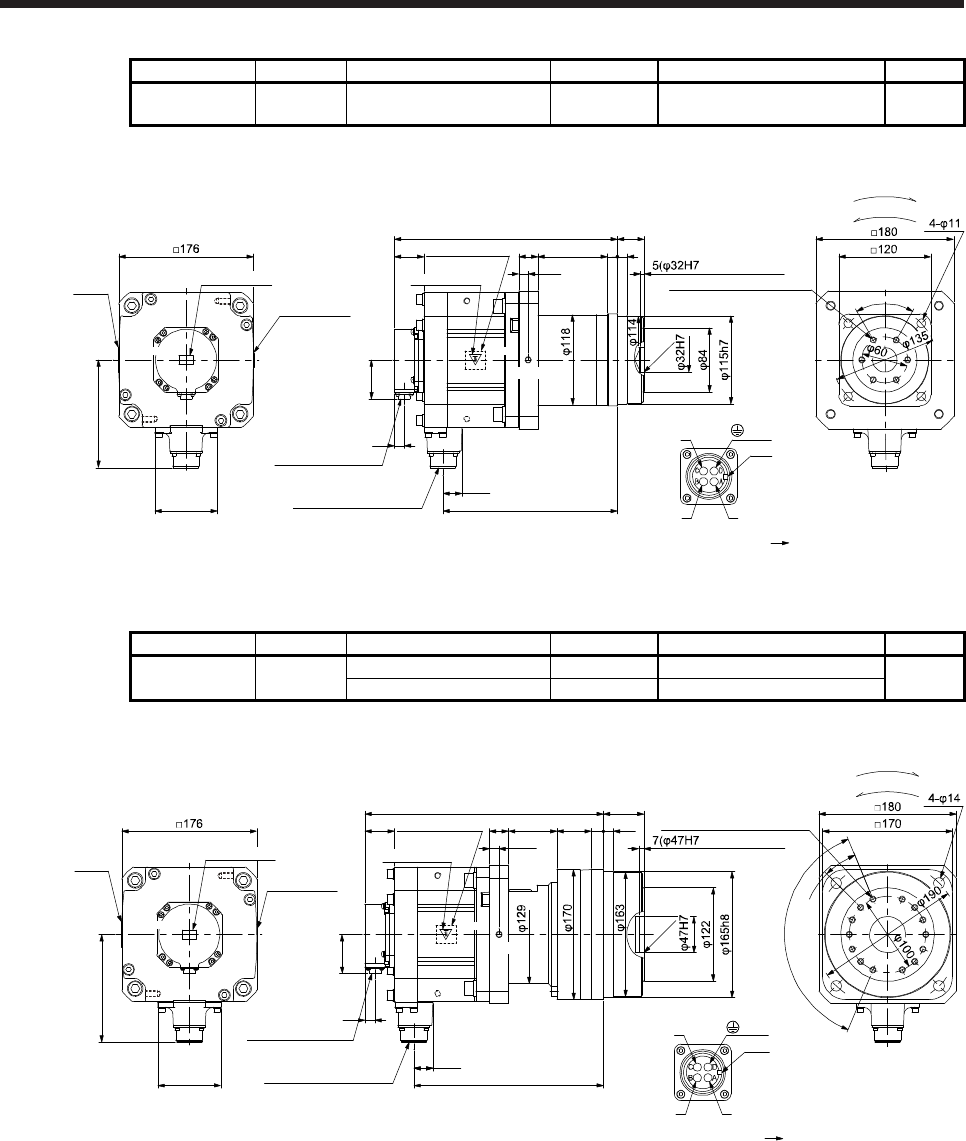
7. HG-SR SERIES
7 - 73
Model Output [kW] Reducer model Reduction ratio Moment of inertia J [× 10-4 kg•m2] Mass [kg]
HG-SR352G5
HG-SR3524G5 3.5 HPG-32A-05-F0PBZI-S 1/5 83.2 24
[Unit: mm]
Caution plate
Bottom
Top Top
Bottom
291.5
Caution plate
Motor plate
(Opposite side)
24.8
227.8
Power supply connector
MS3102A22-22P
Bottom
Top
Bottom
Top
U
W
V
Power supply connector
Motor flange direction
Key
25 91 13
12.5
13
140.9
For reverse rotation command
For forward rotation command
Rotation direction
82
effective range)
C0.5
Motor
plate
Caution plate
60°
6-M8 Screw hole depth 12
38.5
50.9
13
Encoder connector
CMV1-R10P
BC41167*
(PE)
35+0.4
- 0.5
(Note)*
Note. * is a screw hole for eyebolt (M8).
Model Output [kW] Reducer model Reduction ratio Moment of inertia J [× 10-4 kg•m2] Mass [kg]
HG-SR352G5
HG-SR3524G5 3.5 HPG-50A-11-F0BBDF-S 1/11 86.7 34
HPG-50A-21-F0BBDF-S 1/21 85.0
[Unit: mm]
311.5
24.8
247.8
Bottom
Top
U
W
V
Power supply connector
Motor flange direction
Key
25 63 45 16
12.5
For reverse rotation command
For forward rotation command
Rotation direction
6×22.5°(=135°)
22.5°
14-M8 Screw hole depth 12
effective range)
1338.5
50.9
13
Encoder connector
CMV1-R10P
Power supply connector
MS3102A22-22P
Motor plate
(Opposite side)
Motor
plate Caution plate
Caution plate
Bottom
Top Top
Bottom
Bottom
Top
140.9
82
BC41168*
(PE)
53 +0.5
- 0.8
(Note)*
C0.5
Caution plate
Note. * is a screw hole for eyebolt (M8).
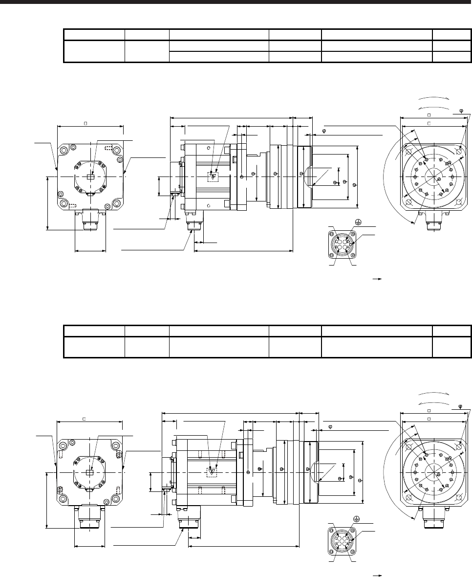
7. HG-SR SERIES
7 - 74
Model Output [kW] Reducer model Reduction ratio Moment of inertia J [× 10-4 kg•m2] Mass [kg]
HG-SR502G5
HG-SR5024G5 5.0 HPG-50A-05-F0BBCF-S 1/5 110 36
HPG-50A-11-F0BBDF-S 1/11 108 38
[Unit: mm]
Motor
plate
Caution plate
Bottom
Top Top
Bottom
327.5
38.5 Motor plate
(Opposite side)
24.8
263.8
50.9
13
Encoder connector
CMV1-R10P
Power supply connector
MS3102A22-22P
Bottom
Top
Bottom
Top
129
170
U
W
V
Power supply connector
Motor flange direction
Key
25 63 45 16
12.5
176
140.9
For reverse rotation command
For forward rotation command
Rotation direction
82
180
190
100
6×22.5°(=135°)
22.5°
14-M8 Screw hole depth 12
4- 14
122
165h8
163
47H7
7( 47H7 effective range)
13
C0.5
170
BC41169*
(PE)
53+0.5
- 0.8
(Note)*
Caution plate Caution plate
Note. * is a screw hole for eyebolt (M8).
Model Output [kW] Reducer model Reduction ratio Moment of inertia J [× 10-4 kg•m2] Mass [kg]
HG-SR702G5
HG-SR7024G5 7.0 HPG-50A-05-F0BBCF-S 1/5 161 43
[Unit: mm]
Bottom
Top Top
Bottom
367.5
38.5
Caution plate
Motor plate
(Opposite side)
32
295.8
50.9
13
Encoder connector
CMV1-R10P
Power supply connector
MS3102A32-17P
Bottom
Top
Bottom
Top
129
170
122
165h8
163
47H7
U
W
V
Power supply connector
Motor flange direction
Key
25 63 45 16
7( 47H7 effective range)
12.5
13
176
149.1
C0.5
82
For reverse rotation command
For forward rotation command
Rotation direction
180
6×22.5°(=135°)
22.5°
14-M8 Screw hole depth 12
4- 14
170
Motor
plate
Caution plate
BC41170*
(PE)
53+0.5
- 0.8
(Note)*
190
100
Caution plate
Note. * is a screw hole for eyebolt (M8).
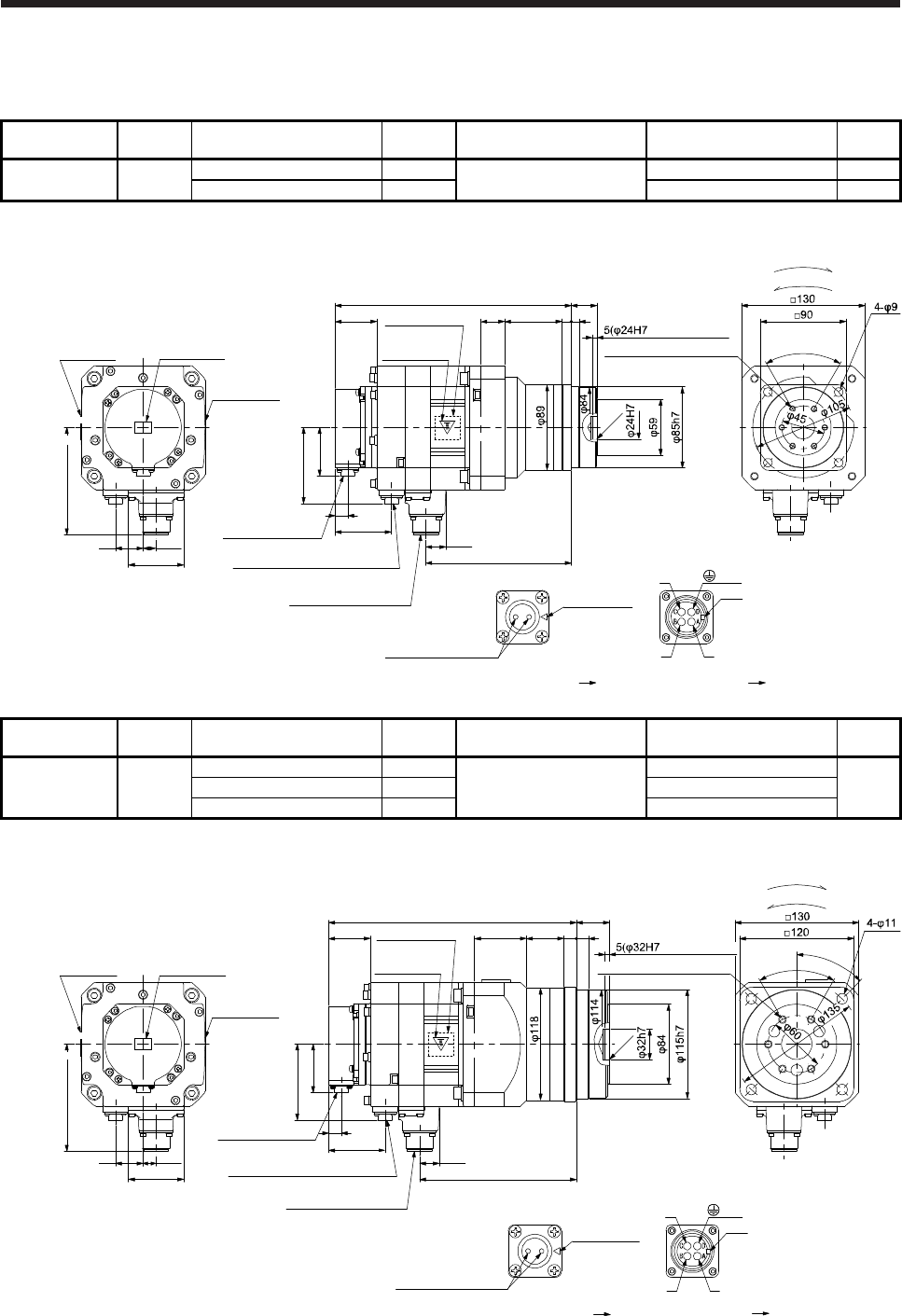
7. HG-SR SERIES
7 - 75
7.7.8 With flange-output type reducer for high precision applications, flange mounting (with an
electromagnetic brake)
Model Output
[kW] Reducer model Reduction
ratio
Brake static friction torque
[N•m]
Moment of inertia J
[× 10-4 kg•m2]
Mass
[kg]
HG-SR52BG5
HG-SR524BG5 0.5 HPG-20A-05-F0KSAWS-S 1/5 8.5 10.1 9.5
HPG-20A-11-F0KSAXS-S 1/11 10.0 9.7
[Unit: mm]
Caution plate
Bottom
Top
Bottom
Top Top
Bottom
248
43.5
Caution plate
Motor plate
(Opposite side)
20.9
152.8
50.9
13
Encoder connector
CMV1-R10P
Power supply connector
MS3102A18-10P
Bottom
Top
U
W
V
Power supply connector
Motor flange direction
Key
Electromagnetic brake connector
CMV1-R2P
79.9
59
Electromagnetic brake
Electromagnetic brake connector
Motor flange direction
Main key
position mark
29
58
13.5
112.5
Motor plate Caution plate
25 60 10 8
effective range)
C0.5
6-M6 Screw hole depth 10
For reverse rotation command
For forward rotation command
Rotation direction
60°
BC41225*
(PE)
27+0.4
- 0.5
Model Output
[kW] Reducer model Reduction
ratio
Brake static friction torque
[N•m]
Moment of inertia J
[× 10-4 kg•m2]
Mass
[kg]
HG-SR52BG5
HG-SR524BG5 0.5
HPG-32A-21-F0MCSYS-S 1/21
8.5
12.4
14
HPG-32A-33-F0MCSZS-S 1/33 12.2
HPG-32A-45-F0MCSZS-S 1/45 12.2
[Unit: mm]
Caution plate
Bottom
Top
Bottom
Top Top
Bottom
260
43.5
Caution plate
Motor plate
(Opposite side)
20.9
164.8
50.9
13
Encoder connector
CMV1-R10P
Power supply connector
MS3102A18-10P
Bottom
Top
U
W
V
Power supply connector
Motor flange direction
Key
Electromagnetic brake connector
CMV1-R2P
79.9
59
Electromagnetic brake
Electromagnetic brake connector
Motor flange direction
Main key
position mark
29
54.5 39.5 13 13
effective range)
58
13.5
112.5
Motor plate Caution plate
45°
For forward rotation command
For forward rotation command
Rotation direction
60°
BC41226*
(PE)
35+0.4
- 0.5
C0.5
6-M8 Screw hole depth 12
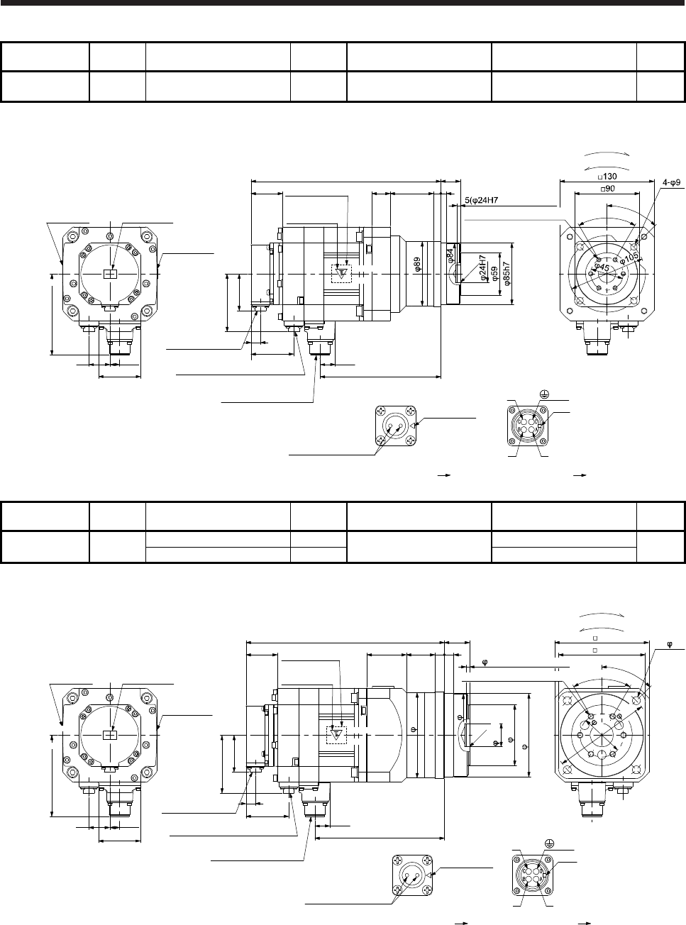
7. HG-SR SERIES
7 - 76
Model Output
[kW] Reducer model Reduction
ratio
Brake static friction torque
[N•m]
Moment of inertia J
[× 10-4 kg•m2]
Mass
[kg]
HG-SR102BG5
HG-SR1024BG5 1.0 HPG-20A-05-F0KSAWS-S 1/5 8.5 14.5 11
[Unit: mm]
Caution plate
Bottom
Top
Bottom
Top Top
Bottom
262
43.5
Caution plate
Motor plate
(Opposite side)
20.9
166.8
50.9
13
Encoder connector
CMV1-R10P
Power supply connector
MS3102A18-10P
Bottom
Top
U
W
V
Power supply connector
Motor flange direction
Key
Electromagnetic brake connector
CMV1-R2P
79.9
59
Electromagnetic brake
Electromagnetic brake connector
Motor flange direction
Main key
position mark
29
58
13.5
112.5
Motor plate Caution plate
25 60 10 8
effective range)
C0.5
45°
6-M6 Screw hole depth 10
For reverse rotation command
For forward rotation command
Rotation direction
60°
BC41227*
(PE)
27+0.4
- 0.5
Model Output
[kW] Reducer model Reduction
ratio
Brake static friction torque
[N•m]
Moment of inertia J
[× 10-4 kg•m2]
Mass
[kg]
HG-SR102BG5
HG-SR1024BG5 1.0 HPG-32A-11-F0MCSPS-S 1/11 8.5 17.1 15
HPG-32A-21-F0MCSYS-S 1/21 16.7
[Unit: mm]
Caution plate
Bottom
Top
Bottom
Top Top
Bottom
274
43.5
Caution plate
Motor plate
(Opposite side)
115h7
20.9
178.8
50.9
13
Encoder connector
CMV1-R10P
Power supply connector
MS3102A18-10P
Bottom
Top
U
W
V
Power supply connector
Motor flange direction
Key
Electromagnetic brake connector
CMV1-R2P
79.9
59
Electromagnetic brake
Electromagnetic brake connector
Motor flange direction
Main key
position mark
29
54.5 39.5 13 13
84
114
118
58
13.5
112.5
Motor plate Caution plate
120
45°
6-M8 Screw hole depth 12
130
For reverse rotation command
For forward rotation command
Rotation direction
4- 11
BC41228*
(PE)
35+0.4
- 0.5
32h7
C0.5
60
135
60°
5( 32H7 effective range)
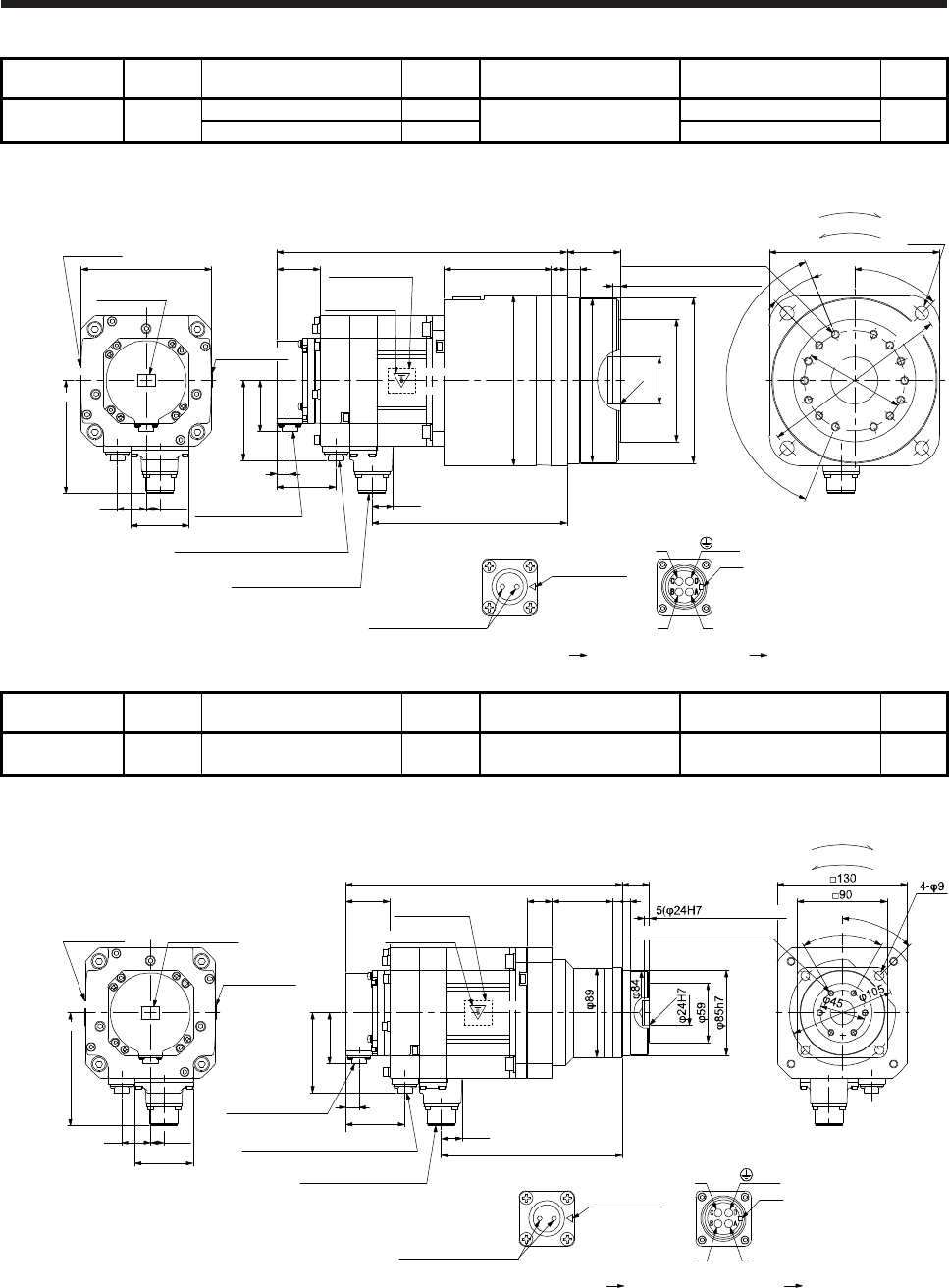
7. HG-SR SERIES
7 - 77
Model Output
[kW] Reducer model Reduction
ratio
Brake static friction torque
[N•m]
Moment of inertia J
[× 10-4 kg•m2]
Mass
[kg]
HG-SR102BG5
HG-SR1024BG5 1.5 HPG-50A-33-F0AABC-S 1/33 8.5 18.5 25
HPG-50A-45-F0AABC-S 1/45 18.4
[Unit: mm]
Motor plate
Caution plate
Bottom
Top
Bottom
Top Top
Bottom
290
43.5
Caution plate
Motor plate
(Opposite side)
φ165h8
20.9
194.8
50.9
13
Bottom
Top
U
W
V
Power supply connector
Motor flange direction
Key
79.9
59
Electromagnetic brake
Electromagnetic brake connector
Motor flange direction
Main key
position mark
29
107 16
φ122
φ163
φ170
58
13.5
112.5
φ47H7
4-φ14
□170
For reverse rotation command
For forward rotation command
Rotation direction
Encoder connector
CMV1-R10P
Power supply connector
MS3102A18-10P
Electromagnetic brake connector
CMV1-R2P
13
45°
7(φ47H7 effective range)
6×22.5°(=135°)
22.5°
C0.5
14-M8 Screw hole depth 12
BC41229A
(PE)
53+0.5
- 0.8
φ190
φ100
□130
Caution plate
Model Output
[kW] Reducer model Reduction
ratio
Brake static friction torque
[N•m]
Moment of inertia J
[× 10-4 kg•m2]
Mass
[kg]
HG-SR152BG5
HG-SR1524BG5 1.5 HPG-20A-05-F0KSAWS-S 1/5 8.5 18.9 13
[Unit: mm]
Caution plate
Bottom
Top
Bottom
Top Top
Bottom
276
43.5
Motor plate
(Opposite side
20.9
180.8
50.9
13
Encoder connector
CMV1-R10P
Power supply connector
MS3102A18-10P
Bottom
Top
U
W
V
Power supply connector
Motor flange direction
Key
Electromagnetic brake connector
CMV1-R2P
79.9
59
Electromagnetic brake
Electromagnetic brake connector
Motor flange direction
Main key
position mark
29
58
13.5
112.5
Motor plate Caution plate
25 60 10 8
effective range)
C0.5
45°
6-M6 Screw hole depth 10
For reverse rotation command
For forward rotation command
Rotation direction
BC41230*
(PE)
27+0.4
- 0.5
60°
Caution plate
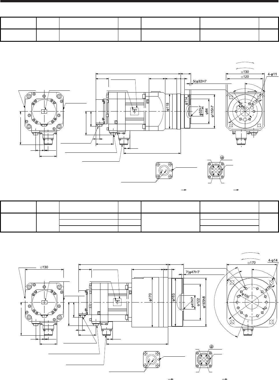
7. HG-SR SERIES
7 - 78
Model Output
[kW] Reducer model Reduction
ratio
Brake static friction torque
[N•m]
Moment of inertia J
[× 10-4 kg•m2]
Mass
[kg]
HG-SR152BG5
HG-SR1524BG5 1.5 HPG-32A-11-F0MCSPS-S 1/11 8.5 21.5 16
[Unit: mm]
Caution plate
Bottom
Top
Bottom
Top Top
Bottom
288
43.5
Caution plate
Motor plate
(Opposite side)
20.9
192.8
50.9
13
Encoder connector
CMV1-R10P
Power supply connector
MS3102A18-10P
Bottom
Top
U
W
V
Power supply connector
Motor flange direction
Key
Electromagnetic brake connector
CMV1-R2P
79.9
59
Electromagnetic brake
Electromagnetic brake connector
Motor flange direction
Main key
position mark
29
54.5 39.5 13 13
effective range)
58
13.5
112.5
Motor plate Caution plate
45°
6-M8 Screw hole depth 12
For reverse rotation command
For forward rotation command
Rotation direction
60°
BC41231*
(PE)
35+0.4
- 0.5
C0.5
Model Output
[kW] Reducer model Reduction
ratio
Brake static friction torque
[N•m]
Moment of inertia J
[× 10-4 kg•m2]
Mass
[kg]
HG-SR152BG5
HG-SR1524BG5 1.5
HPG-50A-21-F0AABC-S 1/21
8.5
23.9
26
HPG-50A-33-F0AABC-S 1/33 22.9
HPG-50A-45-F0AABC-S 1/45 22.8
[Unit: mm]
Motor plate
Bottom
Top
Bottom
Top Top
Bottom
304
43.5
Caution plate
Motor plate
(Opposite side)
20.9
208.8
50.9
13
Bottom
Top
U
W
V
Power supply connector
Motor flange direction
Key
79.9
59
Electromagnetic brake
Electromagnetic brake connector
Motor flange direction
Main key
position mark
29
107 16
58
13.5
112.5
For reverse rotation command
For forward rotation command
Rotation direction
Encoder connector
CMV1-R10P
Power supply connector
MS3102A18-10P
Electromagnetic brake connector
CMV1-R2P
13
45°
effective range)
6×22.5°(=135°)
22.5°
C0.5
14-M8 Screw hole depth 12
BC41232*
(PE)
53+0.5
- 0.8
Caution plate
Caution plate
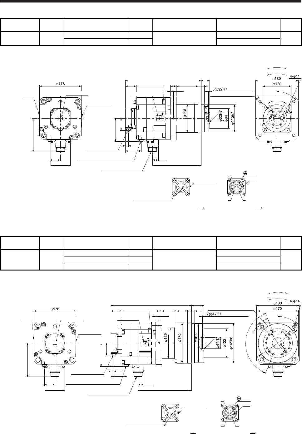
7. HG-SR SERIES
7 - 79
Model Output
[kW] Reducer model Reduction
ratio
Brake static friction torque
[N•m]
Moment of inertia J
[× 10-4 kg•m2]
Mass
[kg]
HG-SR202BG5
HG-SR2024BG5 2.0 HGP-32A-05-F0PBZI-S 1/5 44 61.1 25
HGP-32A-11-F0PBZJ-S 1/11 60.9
[Unit: mm]
Bottom
Top Top
Bottom
317
45.5
Caution plate
Motor plate
(Opposite side)
24.8
203.8
50.9
13
Encoder connector
CMV1-R10P
Power supply connector
MS3102A22-22P
Bottom
Top
Bottom
Top
96.9
Electromagnetic brake connector
CMV1-R2P
66.5
44
25 91 13
12.5
13
140.9
For reverse rotation command
For forward rotation command
Rotation direction
82
45°
effective range)
C0.5
Motor
plate
Caution plate
6-M8 Screw hole depth 12
U
W
V
Power supply connector
Motor flange direction
Key
Electromagnetic brake
Electromagnetic brake connector
Motor flange direction
Main key
position mark
BC41233*
(PE)
35+0.4
- 0.5
(Note)*
60°
Caution plate
Note. * is a screw hole for eyebolt (M8).
Model Output
[kW] Reducer model Reduction
ratio
Brake static friction torque
[N•m]
Moment of inertia J
[× 10-4 kg•m2]
Mass
[kg]
HG-SR202BG5
HG-SR2024BG5 2.0
HPG-50A-21-F0BBDF-S 1/21
44
62.9
35
HPG-50A-33-F0BBDF-S 1/33 61.9
HPG-50A-45-F0BBDF-S 1/45 61.9
[Unit: mm]
Motor
plate
Caution plate
Bottom
Top Top
Bottom
337
45.5
Caution plate
Motor plate
(Opposite side)
24.8
223.8
50.9
13
Encoder connector
CMV1-R10P
Power supply connector
MS3102A22-22P
Bottom
Top
Bottom
Top
96.9
Electromagnetic brake connector
CMV1-R2P
66.5
44
U
W
V
Power supply connector
Motor flange direction
Key
Electromagnetic brake
Electromagnetic brake connector
Motor flange direction
25 63 45 16
12.5
140.9
Main key
position mark
For reverse rotation command
For forward rotation command
Rotation direction
82
45°
6×22.5°(=135°)
22.5°
14-M8 Screw hole depth 12
effective range)
13
BC41234*
(PE)
53+0.5
- 0.8
(Note)*
C0.5
Caution plate
Note. * is a screw hole for eyebolt (M8).
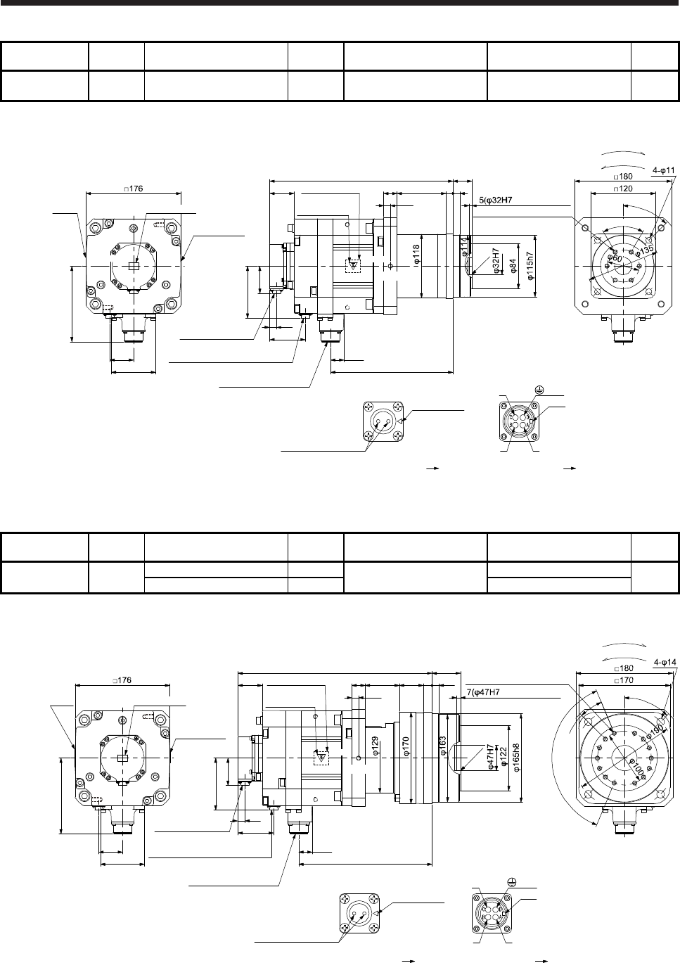
7. HG-SR SERIES
7 - 80
Model Output
[kW] Reducer model Reduction
ratio
Brake static friction torque
[N•m]
Moment of inertia J
[× 10-4 kg•m2]
Mass
[kg]
HG-SR352BG5
HG-SR3524BG5 3.5 HPG-32A-05-F0PBZI-S 1/5 44 92.8 30
[Unit: mm]
Bottom
Top Top
Bottom
341
45.5
Caution plate
Motor plate
(Opposite side)
24.8
227.8
50.9
13
Encoder connector
CMV1-R10P
Power supply connector
MS3102A22-22P
Bottom
Top
Bottom
Top
96.9
Electromagnetic brake connector
CMV1-R2P
66.5
44
U
W
V
Power supply connector
Motor flange direction
Key
Electromagnetic brake
Electromagnetic brake connector
Motor flange direction
25 91 13
12.5
13
140.9
Main key
position mark
For reverse rotation command
For forward rotation command
Rotation direction
82
45°
effective range
C0.5
Motor
plate
Caution plate
60°
6-M8 Screw hole depth 12
BC41235*
(PE)
35+0.4
- 0.5
(Note)*
Caution plate
Note. * is a screw hole for eyebolt (M8).
Model Output
[kW] Reducer model Reduction
ratio
Brake static friction torque
[N•m]
Moment of inertia J
[× 10-4 kg•m2]
Mass
[kg]
HG-SR352BG5
HG-SR3524BG5 3.5 HPG-50A-11-F0BBDF-S 1/11 44 96.3 40
HPG-50A-21-F0BBDF-S 1/21 94.6
[Unit: mm]
Motor
plate
Caution plate
Bottom
Top Top
Bottom
361
45.5
Caution plate
Motor plate
(Opposite side)
24.8
247.8
50.9
13
Encoder connector
CMV1-R10P
Power supply connector
MS3102A22-22P
Bottom
Top
Bottom
Top
96.9
Electromagnetic brake connector
CMV1-R2P
66.5
44
U
W
V
Power supply connector
Motor flange direction
Key
Electromagnetic brake
Electromagnetic brake connector
Motor flange direction
25 63 45 16
12.5
140.9
Main key
position mark
For reverse rotation command
For forward rotation command
Rotation direction
82
45°
6×22.5°(=135°)
22.5°
14-M8 Screw hole depth 12
effective range)
13
BC41236*
(PE)
53+0.5
- 0.8
(Note)*
C0.5
Caution plate
Note. * is a screw hole for eyebolt (M8).
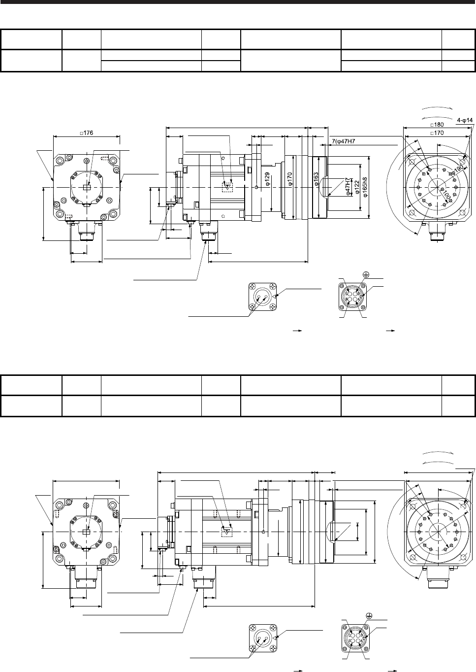
7. HG-SR SERIES
7 - 81
Model Output
[kW] Reducer model Reduction
ratio
Brake static friction torque
[N•m]
Moment of inertia J
[× 10-4 kg•m2]
Mass
[kg]
HG-SR502BG5
HG-SR5024BG5 5.0 HPG-50A-05-F0BBCF-S 1/5 44 119 42
HPG-50A-11-F0BBDF-S 1/11 117 44
[Unit: mm]
Motor
plate Caution plate
Caution plate
Bottom
Top Top
Bottom
377
45.5
Caution plate
Motor plate
(Opposite side)
24.8
263.8
50.9
13
Encoder connector
CMV1-R10P
Power supply connector
MS3102A22-22P
Bottom
Top
Bottom
Top
96.9
Electromagnetic brake connector
CMV1-R2P
66.5
44
U
W
V
Power supply connector
Motor flange direction
Key
Electromagnetic brake
Electromagnetic brake connector
Motor flange direction
25 63 45 16
12.5
140.9
Main key
position mark
For reverse rotation command
For forward rotation command
Rotation direction
82
45°
6×22.5°(=135°)
22.5°
14-M8 Screw hole depth 12
effective range)
13
C0.5
BC41237*
(PE)
53+0.5
- 0.8
(Note)*
Note. * is a screw hole for eyebolt (M8).
Model Output
[kW] Reducer model Reduction
ratio
Brake static friction torque
[N•m]
Moment of inertia J
[× 10-4 kg•m2]
Mass
[kg]
HG-SR702BG5
HG-SR7024BG5 7.0 HPG-50A-05-F0BBCF-S 1/5 44 171 49
[Unit: mm]
Motor
plate
Caution plate
Bottom
Top Top
Bottom
417
45.5
Caution plate
Motor plate
(Opposite side
32
295.8
50.9
13
Encoder connector
CMV1-R10P
Power supply connector
MS3102A32-17P
Bottom
Top
Bottom
Top
96.9
Electromagnetic brake connector
CMV1-R2P
66.5
44
φ129
φ170
φ122
φ165h8
φ163
φ47H7
U
W
V
Power supply connector
Motor flange direction
Key
Electromagnetic brake
Electromagnetic brake connector
Motor flange direction
25 63 45 16
7(φ47H7 effective range)
12.5
13
□176
149.1
Main key
position mark
C0.5
82
For reverse rotation command
For forward rotation command
Rotation direction
□180
45°
22.5°
14-M8 Screw hole depth 12
4-φ14
□170
BC41238A
(PE)
53+0.5
- 0.8
(Note)*
6×22.5°(=135°)
φ190
φ100
Caution plate
Note. * is a screw hole for eyebolt (M8).
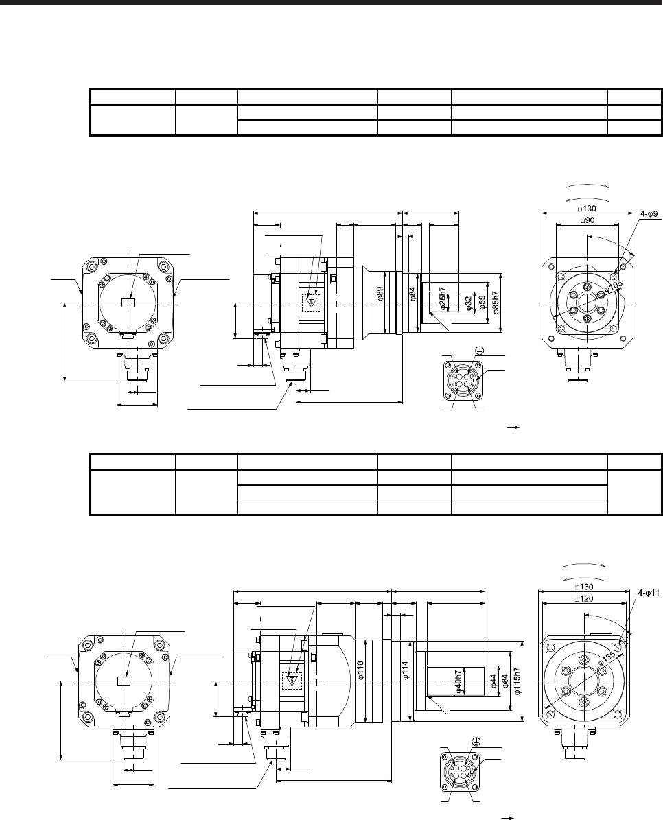
7. HG-SR SERIES
7 - 82
7.7.9 With shaft-output type reducer for high precision applications, flange mounting (without an
electromagnetic brake)
Model Output [kW] Reducer model Reduction ratio Moment of inertia J [× 10-4 kg•m2] Mass [kg]
HG-SR52G7
HG-SR524G7 0.5 HPG-20A-05-J2KSAWS-S 1/5 7.95 8.0
HPG-20A-11-J2KSAXS-S 1/11 7.82 8.2
[Unit: mm]
213.5
20.9
152.8
Bottom
Top
U
W
V
Power supply connector
Motor flange direction
Key
25 60 10
80
45°
38.2
Caution plate
Motor plate
(Opposite side)
50.9
13
Encoder connector
CMV1-R10P
Power supply connector
MS3102A18-10P
Motor
plate
Caution plate
Caution plate
Bottom
Top
Bottom
Top Top
Bottom
58
13.5
112.5
For reverse rotation command
For forward rotation command
Rotation direction
4227
8
R0.4
BC41171*
(PE)
Model Output [kW] Reducer model Reduction ratio Moment of inertia J [× 10-4 kg•m2] Mass [kg]
HG-SR52G7
HG-SR524G7 0.5
HPG-32A-21-J2MCSYS-S 1/21 10.2
13
HPG-32A-33-J2MCSZS-S 1/33 9.96
HPG-32A-45-J2MCSZS-S 1/45 9.96
[Unit: mm]
Motor
plate
Caution plate
Caution plate
Bottom
Top
Bottom
Top Top
Bottom
225.5
38.2
Caution plate
Motor plate
(Opposite side)
20.9
164.8
50.9
13
Encoder connector
CMV1-R10P
Power supply connector
MS3102A18-10P
Bottom
Top
U
W
V
Power supply connector
Motor flange direction
Key
54.5 39.5 13
13
133
58
13.5
112.5
8235
45°
For reverse rotation command
For forward rotation command
Rotation direction
BC41172*
(PE)
R0.4
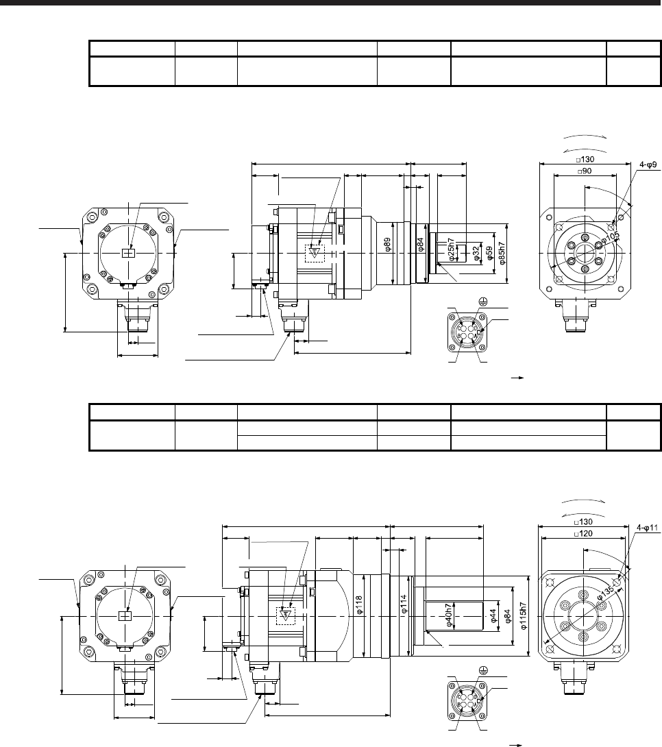
7. HG-SR SERIES
7 - 83
Model Output [kW] Reducer model Reduction ratio Moment of inertia J [× 10-4 kg•m2] Mass [kg]
HG-SR102G7
HG-SR1024G7 1.0 HPG-20A-05-J2KSAWS-S 1/5 12.3 9.4
[Unit: mm]
227.5
20.9
166.8
Bottom
Top
U
W
V
Power supply connector
Motor flange direction
Key
25 60 10
80
45°
38.2
Caution plate
Motor plate
(Opposite side)
50.9
13
Encoder connector
CMV1-R10P
Power supply connector
MS3102A18-10P
Motor plate
Caution plate
Caution plate
Bottom
Top
Bottom
Top Top
Bottom
58
13.5
112.5
For reverse rotation command
For forward rotation command
Rotation direction
42
27
8
R0.4
BC41173*
(PE)
Model Output [kW] Reducer model Reduction ratio Moment of inertia J [× 10-4 kg•m2] Mass [kg]
HG-SR102G7
HG-SR1024G7 1.0 HPG-32A-11-J2MCSPS-S 1/11 15.0 15
HPG-32A-21-J2MCSYS-S 1/21 14.5
[Unit: mm]
Motor plate
Caution plate
Bottom
Top
Bottom
Top Top
Bottom
239.5
38.2 Motor plate
(Opposite side)
20.9
178.8
50.9
13
Encoder connector
CMV1-R10P
Power supply connector
MS3102A18-10P
Bottom
Top
U
W
V
Power supply connector
Motor flange direction
Key
54.5 39.5 13
13
133
58
13.5
112.5
8235
45°
For reverse rotation command
For forward rotation command
Rotation direction
BC41174*
(PE)
R0.4
Caution plate
Caution plate
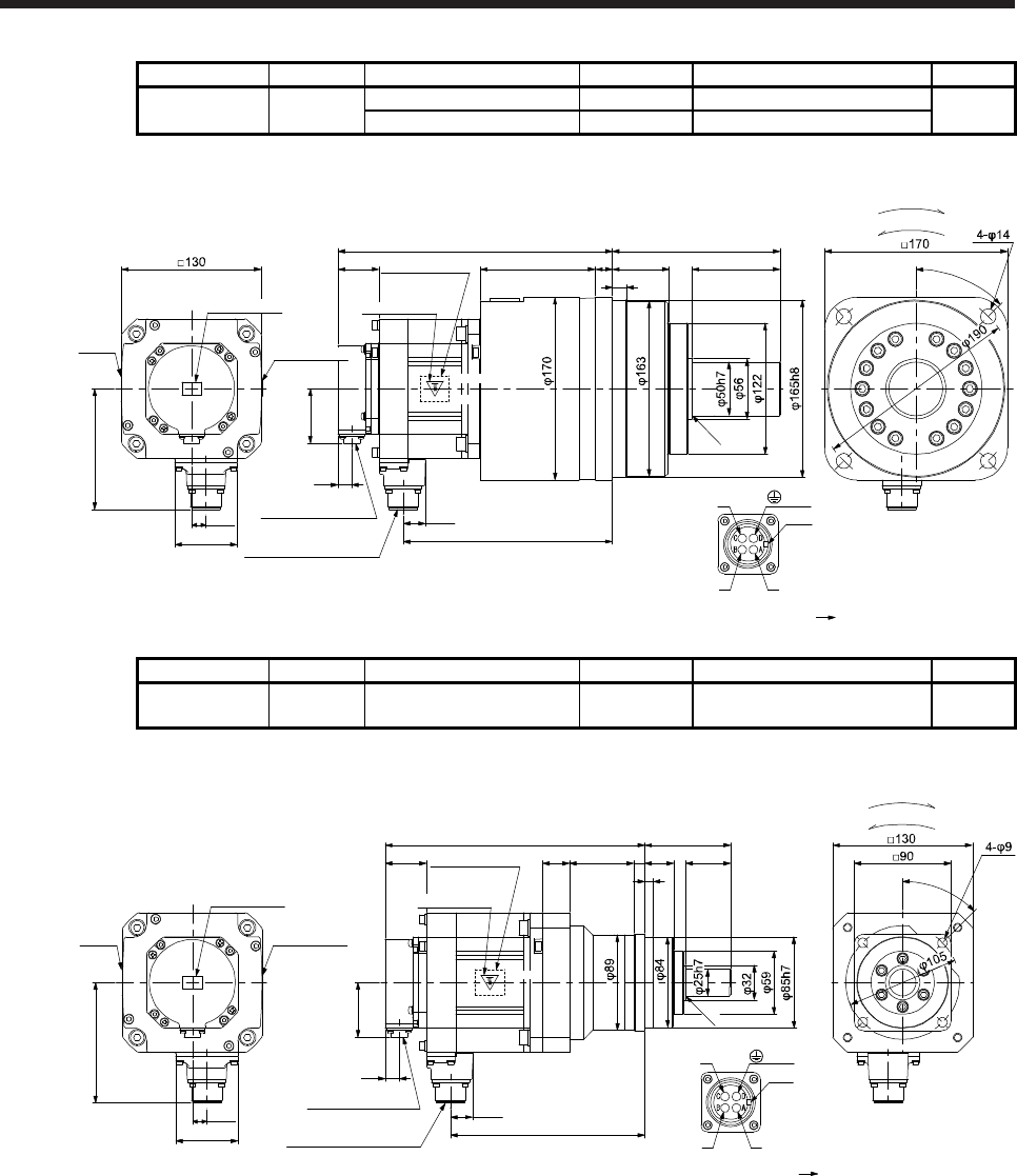
7. HG-SR SERIES
7 - 84
Model Output [kW] Reducer model Reduction ratio Moment of inertia J [× 10-4 kg•m2] Mass [kg]
HG-SR102G7
HG-SR1024G7 1.0 HPG-50A-33-J2AABC-S 1/33 16.3 26
HPG-50A-45-J2AABC-S 1/45 16.3
[Unit: mm]
Motor
plate
Caution plate
Caution plate
Bottom
Top
Bottom
Top Top
Bottom
255.5
38.2 Motor plate
(Opposite side)
20.9
194.8
50.9
13
Encoder connector
CMV1-R10P
Power supply connector
MS3102A18-10P
Bottom
Top
U
W
V
Power supply connector
Motor flange direction
Key
58
13.5
112.5
107 16
156
8253
For reverse rotation command
For forward rotation command
Rotation direction
13
45°
R0.4
BC41175*
(PE)
Caution plate
Model Output [kW] Reducer model Reduction ratio Moment of inertia J [× 10-4 kg•m2] Mass [kg]
HG-SR152G7
HG-SR1524G7 1.5 HPG-20A-05-J2KSAWS-S 1/5 16.7 11
[Unit: mm]
241.5
20.9
180.8
Bottom
Top
U
W
V
Power supply connector
Motor flange direction
Key
25 60 10
80
45°
38.2
Caution plate
Motor plate
(Opposite side)
50.9
13
Encoder connector
CMV1-R10P
Power supply connector
MS3102A18-10P
Motor
plate
Caution plate
Caution plate
Bottom
Top
Bottom
Top Top
Bottom
58
13.5
112.5
For reverse rotation command
For forward rotation command
Rotation direction
4227
8
R0.4
BC41176*
(PE)
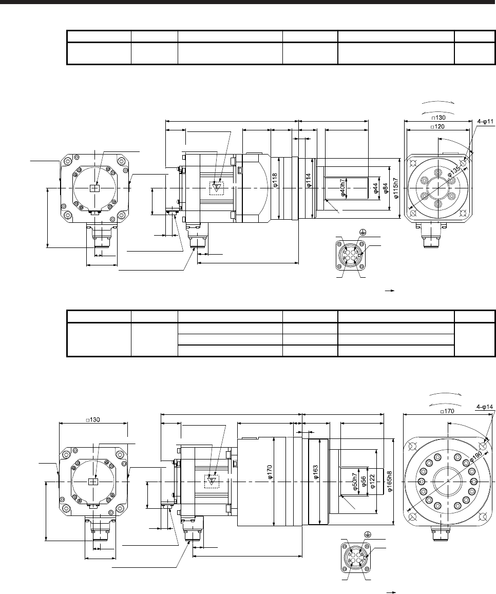
7. HG-SR SERIES
7 - 85
Model Output [kW] Reducer model Reduction ratio Moment of inertia J [× 10-4 kg•m2] Mass [kg]
HG-SR152G7
HG-SR1524G7 1.5 HPG-32A-11-J2MCSPS-S 1/11 19.4 16
[Unit: mm]
Caution plate
Caution plate
Bottom
TopTop Top
Bottom
253.5
38.2 Motor plate
(Opposite side)
20.9
192.8
50.9
13
Encoder connector
CMV1-R10P
Power supply connector
MS3102A18-10P
Bottom
Top
U
W
V
Power supply connector
Motor flange direction
Key
54.5 39.5 13
13
133
58
13.5
112.5
82
35
45°
For reverse rotation command
For forward rotation command
Rotation direction
BC41177*
(PE)
R0.4
Motor plate
Bottom
Caution plate
Model Output [kW] Reducer model Reduction ratio Moment of inertia J [× 10-4 kg•m2] Mass [kg]
HG-SR152G7
HG-SR1524G7 1.5
HPG-50A-21-J2AABC-S 1/21 21.7
27
HPG-50A-33-J2AABC-S 1/33 20.7
HPG-50A-45-J2AABC-S 1/45 20.7
[Unit: mm]
Bottom
Top
Top Top
Bottom
269.5
38.2
Caution plate
Motor plate
(Opposite side)
20.9
208.8
50.9
13
Encoder connector
CMV1-R10P
Power supply connector
MS3102A18-10P
Bottom
Top
U
W
V
Power supply connector
Motor flange direction
Key
58
13.5
112.5
107 16
156
8253
For reverse rotation command
For forward rotation command
Rotation direction
13
45°
R0.4
BC41178*
(PE)
Motor
plate
Bottom
Caution plate
Caution plate
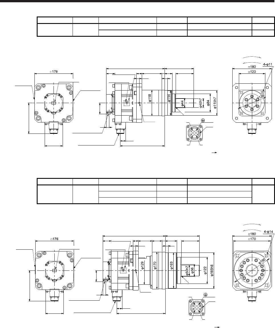
7. HG-SR SERIES
7 - 86
Model Output [kW] Reducer model Reduction ratio Moment of inertia J [× 10-4 kg•m2] Mass [kg]
HG-SR202G7
HG-SR2024G7 2.0 HPG-32A-05-J2PBZI-S 1/5 51.7 20
HPG-32A-11-J2PBZJ-S 1/11 51.3 21
[Unit: mm]
267.5
24.8
203.8
Bottom
Top
U
W
V
Power supply connector
Motor flange direction
Key
25 91 13 35 82
133
12.5 13
For reverse rotation command
For forward rotation command
Rotation direction
R0.4
38.5
50.9
13
Encoder connector
CMV1-R10P
Power supply connector
MS3102A22-22P
Caution plate
Motor plate
(Opposite side)
Motor plate
Caution plate
Bottom
Top Top
Bottom
Bottom
Top
140.9
82
BC41179*
(PE)
(Note)*
Caution plate
Note. * is a screw hole for eyebolt (M8).
Model Output [kW] Reducer model Reduction ratio Moment of inertia J [× 10-4 kg•m2] Mass [kg]
HG-SR202G7
HG-SR2024G7 2.0
HPG-50A-21-J2BBDF-S 1/21 53.3
32
HPG-50A-33-J2BBDF-S 1/33 52.2
HPG-50A-45-J2BBDF-S 1/45 52.2
[Unit: mm]
287.5
223.8
Bottom
Top
U
W
V
Power supply connector
Motor flange direction
Key
25 63 45 16 53 82
156
12.5 13
R0.4
For reverse rotation command
For forward rotation command
Rotation direction
24.8
Power supply connector
MS3102A22-22P
38.5
50.9
13
Encoder connector
CMV1-R10P
Caution plate
Motor plate
(Opposite side)
Motor plate Caution plate
Caution plate
Bottom
Top Top
Bottom
Bottom
Top
140.9
82
BC41180*
(PE)
(Note)*
Note. * is a screw hole for eyebolt (M8).
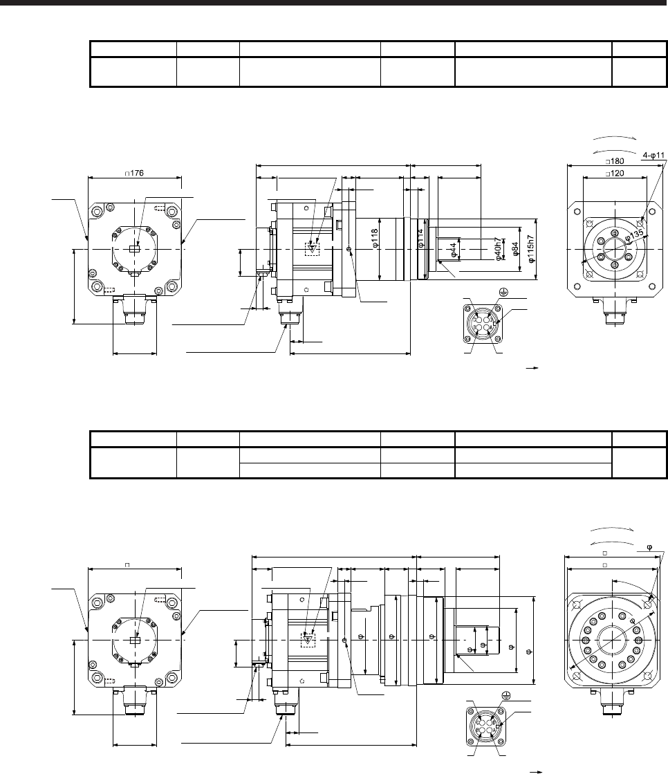
7. HG-SR SERIES
7 - 87
Model Output [kW] Reducer model Reduction ratio Moment of inertia J [× 10-4 kg•m2] Mass [kg]
HG-SR352G7
HG-SR3524G7 3.5 HPG-32A-05-J2PBZI-S 1/5 83.5 25
[Unit: mm]
291.5
24.8
227.8
Bottom
Top
U
W
V
Power supply connector
Motor flange direction
Key
25 91 13 35 82
133
12.5 13
For reverse rotation command
For forward rotation command
Rotation direction
R0.4
38.5
50.9
13
Encoder connector
CMV1-R10P
Power supply connector
MS3102A22-22P
Caution plate
Motor plate
(Opposite side)
Motor
plate
Caution plate
Bottom
Top Top
Bottom
Bottom
Top
140.9
82
BC41181*
(PE)
(Note)*
Caution plate
Note. * is a screw hole for eyebolt (M8).
Model Output [kW] Reducer model Reduction ratio Moment of inertia J [× 10-4 kg•m2] Mass [kg]
HG-SR352G7
HG-SR3524G7 3.5 HPG-50A-11-J2BBDF-S 1/11 87.0 37
HPG-50A-21-J2BBDF-S 1/21 85.1
[Unit: mm]
311.5
247.8
Bottom
Top
129
170
122
165h8
163
56
U
W
V
Power supply connector
Motor flange direction
Key
25 63 45 16 53 82
156
12.5 13
180
R0.4
45°
4- 14
For reverse rotation command
For forward rotation command
Rotation direction
170
24.8
Power supply connector
MS3102A22-22P
38.5
50.9
13
ncoder connector
CMV1-R10P
Caution plate
Motor plate
(Opposite side)
Motor
plate Caution plate
Caution plate
Bottom
Top Top
Bottom
Bottom
Top
176
140.9
82
BC41182*
(PE)
(Note)*
50h7
190
Note. * is a screw hole for eyebolt (M8).
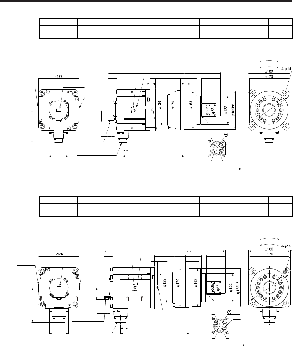
7. HG-SR SERIES
7 - 88
Model Output [kW] Reducer model Reduction ratio Moment of inertia J [× 10-4 kg•m2] Mass [kg]
HG-SR502G7
HG-SR5024G7 5.0 HPG-50A-05-J2BBCF-S 1/5 111 39
HPG-50A-11-J2BBDF-S 1/11 108 41
[Unit: mm]
Caution plate
Bottom
Top Top
Bottom
327.5
24.8
263.8
Power supply connector
MS3102A22-22P
Bottom
Top
Bottom
Top
U
W
V
Power supply connector
Motor flange direction
Key
25 63 45 16 53 82
156
12.5 13
R0.4
140.9
For reverse rotation command
For forward rotation command
Rotation direction
82
Motor plate
(Opposite side)
38.5
50.9
13
Encoder connector
CMV1-R10P
Motor plate
Caution plate
BC41183*
(PE)
(Note)*
Caution plate
Note. * is a screw hole for eyebolt (M8).
Model Output [kW] Reducer model Reduction ratio Moment of inertia J [× 10-4 kg•m2] Mass [kg]
HG-SR702G7
HG-SR7024G7 7.0 HPG-50A-05-J2BBCF-S 1/5 163 46
[Unit: mm]
367.5
32
295.8
Power supply connector
MS3102A32-17P
Bottom
Top
U
W
V
Power supply connector
Motor flange direction
Key
25 63 45 16 53 82
156
12.5 13
R0.4
For reverse rotation command
For forward rotation command
Rotation direction
38.5
13
Encoder connector
CMV1-R10P
Caution plate
Bottom
Top Top
Bottom
Bottom
Top
149.1
82
Motor plate
50.9
Motor plate
(Opposite side)
Caution plate
BC41184*
(PE)
(Note)*
Caution plate
Note. * is a screw hole for eyebolt (M8).
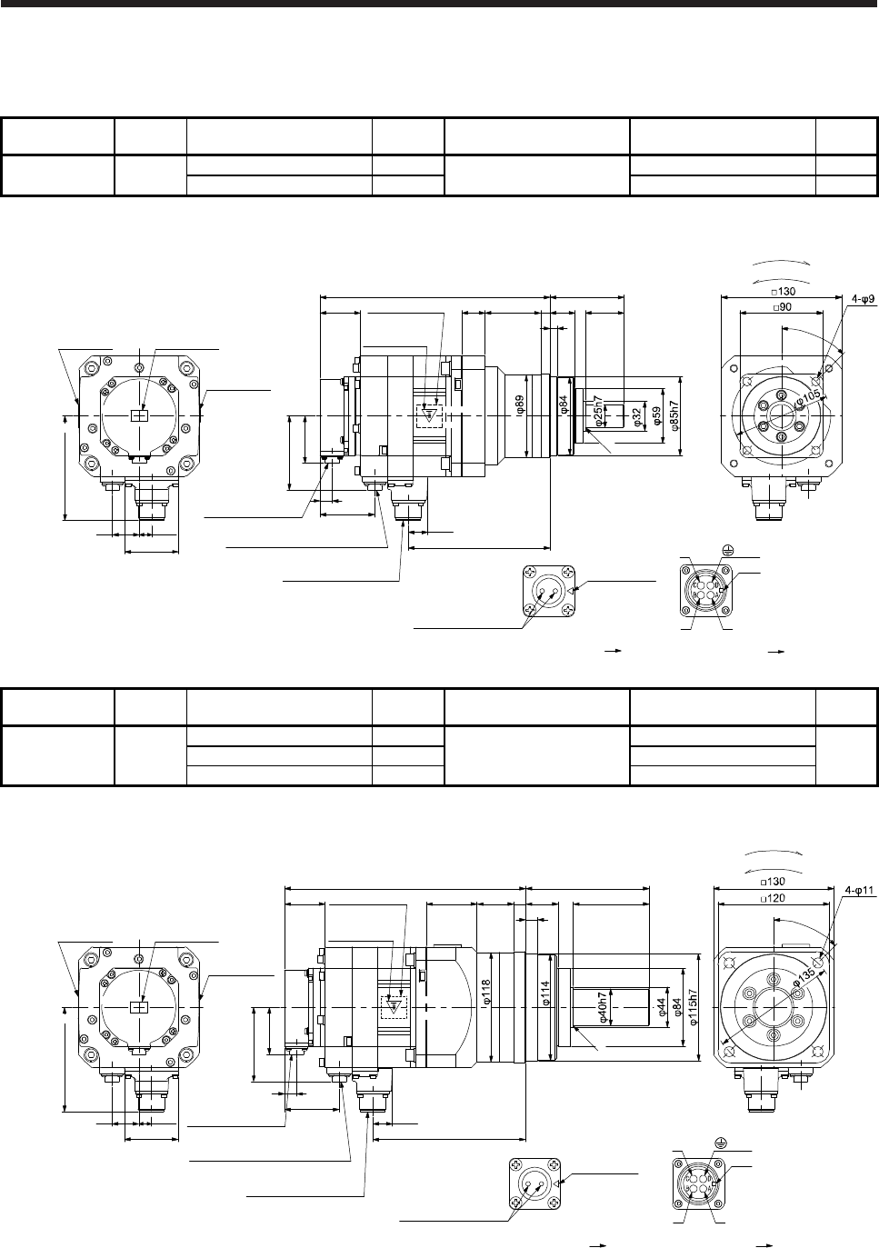
7. HG-SR SERIES
7 - 89
7.7.10 With shaft-output type reducer for high precision applications, flange mounting (with an
electromagnetic brake)
Model Output
[kW] Reducer model Reduction
ratio
Brake static friction torque
[N•m]
Moment of inertia J
[× 10-4 kg•m2]
Mass
[kg]
HG-SR52BG7
HG-SR524BG7 0.5 HPG-20A-05-J2KSAWS-S 1/5 8.5 10.2 9.9
HPG-20A-11-J2KSAXS-S 1/11 10.0 11
[Unit: mm]
Caution plate
Bottom
Top
Bottom
Top
Bottom
248
43.5
Caution plate
Motor plate
(Opposite side)
20.9
152.8
50.9
13
Encoder connector
CMV1-R10P
Bottom
Top
U
W
V
Power supply connector
Motor flange direction
Key
Electromagnetic brake connector
CMV1-R2P
79.9
59
Electromagnetic brake
Electromagnetic brake connector
Motor flange direction
Main key
position mark
29
58
13.5
112.5
Motor plate Caution plate
25 60 10
45°
For reverse rotation command
For forward rotation command
Rotation direction
80
4227
8
R0.4
BC41239*
(PE)
Power supply connector
MS3102A18-10P
Top
Model Output
[kW] Reducer model Reduction
ratio
Brake static friction torque
[N•m]
Moment of inertia J
[× 10-4 kg•m2]
Mass
[kg]
HG-SR52BG7
HG-SR524BG7 0.5
HPG-32A-21-J2MCSYS-S 1/21
8.5
12.4
15
HPG-32A-33-J2MCSZS-S 1/33 12.2
HPG-32A-45-J2MCSZS-S 1/45 12.2
[Unit: mm]
Motor plate Caution plate
Caution plate
Bottom
Top
Bottom
Top Top
Bottom
260
43.5
Caution plate
Motor plate
(Opposite side)
20.9
164.8
50.9
13
Encoder connector
CMV1-R10P
Power supply connector
MS3102A18-10P
Bottom
Top
U
W
V
Power supply connector
Motor flange direction
Key
Electromagnetic brake connector
CMV1-R2P
79.9
59
Electromagnetic brake
Electromagnetic brake connector
Motor flange direction
Main key
position mark
29
54.5 39.5 13
13
133
58
13.5
112.5
8235
45°
For reverse rotation command
For forward rotation command
Rotation direction
BC41240*
R0.4
(PE)
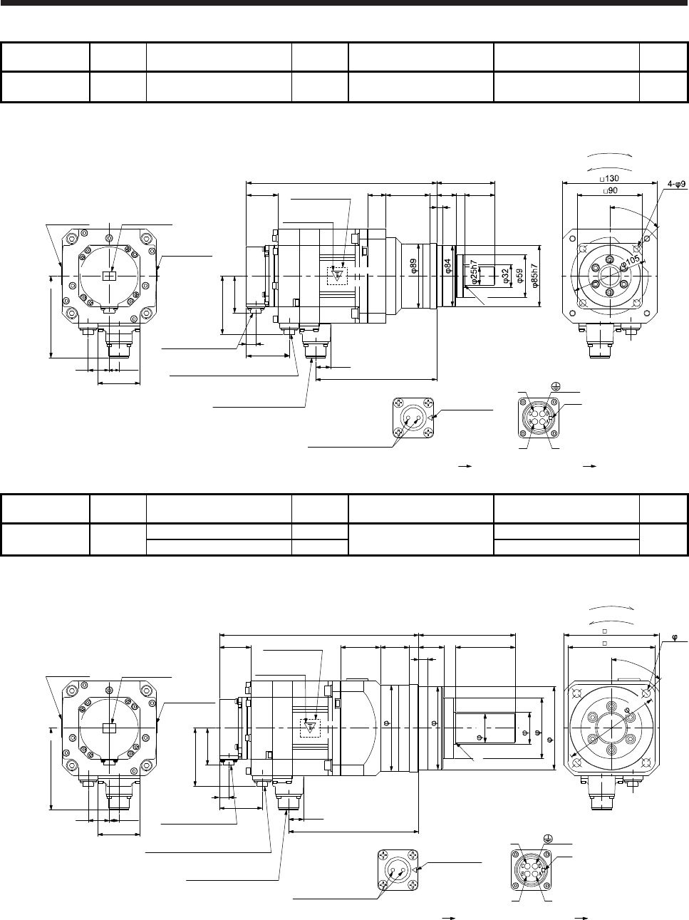
7. HG-SR SERIES
7 - 90
Model Output
[kW] Reducer model Reduction
ratio
Brake static friction torque
[N•m]
Moment of inertia J
[× 10-4 kg•m2]
Mass
[kg]
HG-SR102BG7
HG-SR1024BG7 1.0 HPG-20A-05-J2KSAWS-S 1/5 8.5 14.5 12
[Unit: mm]
Caution plate
Bottom
Top
Bottom
Top Top
Bottom
262
43.5
Caution plate
Motor plate
(Opposite side)
20.9
166.8
50.9
13
Encoder connector
CMV1-R10P
Power supply connector
MS3102A18-10P
Bottom
Top
U
W
V
Power supply connector
Motor flange direction
Key
Electromagnetic brake connector
CMV1-R2P
79.9
59
Electromagnetic brake
Electromagnetic brake connector
Motor flange direction
Main key
position mark
29
58
13.5
112.5
Motor plate Caution plate
25 60 10
45°
For reverse rotation command
For forward rotation command
Rotation direction
80
42 27
8
R0.4
BC41241*
(PE)
Model Output
[kW] Reducer model Reduction
ratio
Brake static friction torque
[N•m]
Moment of inertia J
[× 10-4 kg•m2]
Mass
[kg]
HG-SR102BG7
HG-SR1024BG7 1.0 HPG-32A-11-J2MCSPS-S 1/11 8.5 17.2 17
HPG-32A-21-J2MCSYS-S 1/21 16.7
[Unit: mm]
Motor plate Caution plate
Caution plate
Bottom
Top
Bottom
Top Top
Bottom
274
43.5
Caution plate
Motor plate
(Opposite side)
115h7
20.9
178.8
50.9
13
Encoder connector
CMV1-R10P
Power supply connector
MS3102A18-10P
Bottom
Top
U
W
V
Power supply connector
Motor flange direction
Key
Electromagnetic brake connector
CMV1-R2P
79.9
59
Electromagnetic brake
Electromagnetic brake connector
Motor flange direction
Main key
position mark
29
54.5 39.5 13
13
133
84
114
118
58
13.5
112.5
40h7
44
82
35 120 4- 11
45°
130
For reverse rotation command
For forward rotation command
Rotation direction
BC41242*
(PE)
R0.4
135
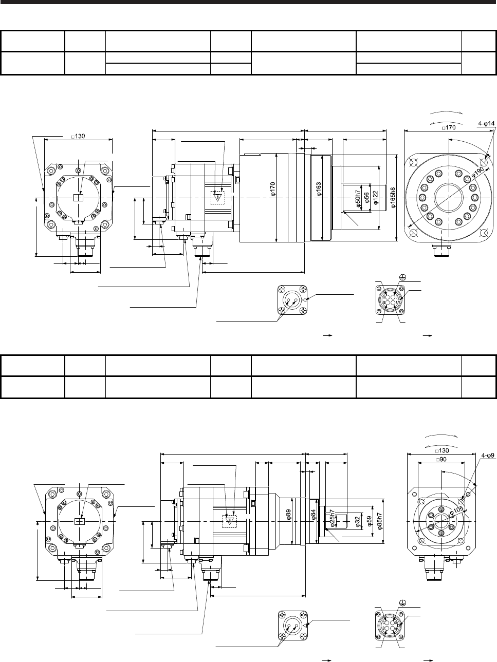
7. HG-SR SERIES
7 - 91
Model Output
[kW] Reducer model Reduction
ratio
Brake static friction torque
[N•m]
Moment of inertia J
[× 10-4 kg•m2]
Mass
[kg]
HG-SR102BG7
HG-SR1024BG7 1.0 HPG-50A-33-J2AABC-S 1/33 8.5 18.5 28
HPG-50A-45-J2AABC-S 1/45 18.5
[Unit: mm]
Motor plate
Caution plate
Bottom
Top
Bottom
Top Top
Bottom
290
43.5
Caution plate
Motor plate
(Opposite side)
20.9
194.8
50.9
13
Bottom
Top
U
W
V
Power supply connector
Motor flange direction
Key
79.9
59
Electromagnetic brake
Electromagnetic brake connector
Motor flange direction
Main key
position mark
29
107 16
156
58
13.5
112.5
82
53
For reverse rotation command
For forward rotation command
Rotation direction
Encoder connector
CMV1-R10P
Power supply connector
MS3102A18-10P
Electromagnetic brake connector
CMV1-R2P
13
45°
R0.4
BC41243*
(PE)
Caution plate
Model Output
[kW] Reducer model Reduction
ratio
Brake static friction torque
[N•m]
Moment of inertia J
[× 10-4 kg•m2]
Mass
[kg]
HG-SR152BG7
HG-SR1524BG7 1.5 HPG-20A-05-J2KSAWS-S 1/5 8.5 18.9 13
[Unit: mm]
Caution plate
Bottom
Top
Bottom
Top Top
Bottom
276
43.5
Caution plate
Motor plate
(Opposite side)
20.9
180.8
50.9
13
Bottom
Top
U
W
V
Power supply connector
Motor flange direction
Key
79.9
59
Electromagnetic brake
Electromagnetic brake connector
Motor flange direction
Main key
position mark
29
58
13.5
112.5
Motor plate Caution plate
25 60 10
45°
For reverse rotation command
For forward rotation command
Rotation direction
80
4227
8
Encoder connector
CMV1-R10P
Power supply connector
MS3102A18-10P
Electromagnetic brake connector
CMV1-R2P
R0.4
BC41244*
(PE)
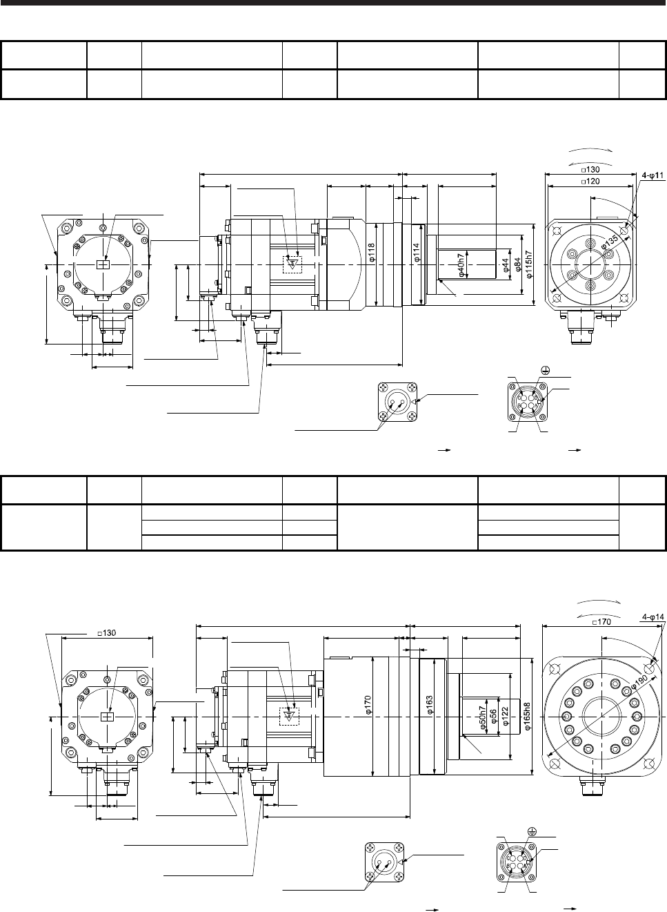
7. HG-SR SERIES
7 - 92
Model Output
[kW] Reducer model Reduction
ratio
Brake static friction torque
[N•m]
Moment of inertia J
[× 10-4 kg•m2]
Mass
[kg]
HG-SR152BG7
HG-SR1524BG7 1.5 HPG-32A-11-J2MCSPS-S 1/11 8.5 21.6 18
[Unit: mm]
Motor plate Caution plate
Caution plate
Bottom
Top
Bottom
Top Top
Bottom
288
43.5
Caution plate
Motor plate
(Opposite side)
20.9
192.8
50.9
13
Bottom
Top
U
W
V
Power supply connector
Motor flange direction
Key
79.9
59
Electromagnetic brake
Electromagnetic brake connector
Motor flange direction
Main key
position mark
29
54.5 39.5 13
13
133
58
13.5
112.5
8235
45°
For reverse rotation command
For forward rotation command
Rotation direction
Encoder connector
CMV1-R10P
Power supply connector
MS3102A18-10P
Electromagnetic brake connector
CMV1-R2P
BC41245*
(PE)
R0.4
Model Output
[kW] Reducer model Reduction
ratio
Brake static friction torque
[N•m]
Moment of inertia J
[× 10-4 kg•m2]
Mass
[kg]
HG-SR152BG7
HG-SR1524BG7 1.5
HPG-50A-21-J2AABC-S 1/21
8.5
23.9
29
HPG-50A-33-J2AABC-S 1/33 22.9
HPG-50A-45-J2AABC-S 1/45 22.9
[Unit: mm]
Motor plate
Caution plate
Bottom
Top
Bottom
Top Top
Bottom
304
43.5
Caution plate
Motor plate
(Opposite side)
20.9
208.8
50.9
13
Bottom
Top
U
W
V
Power supply connector
Motor flange direction
Key
79.9
59
Electromagnetic brake
Electromagnetic brake connector
Motor flange direction
Main key
position mark
29
107 16
156
58
13.5
112.5
8253
For reverse rotation command
For forward rotation command
Rotation direction
Encoder connector
CMV1-R10P
Power supply connector
MS3102A18-10P
Electromagnetic brake connector
CMV1-R2P
13
45°
R0.4
BC41246*
(PE)
Caution plate
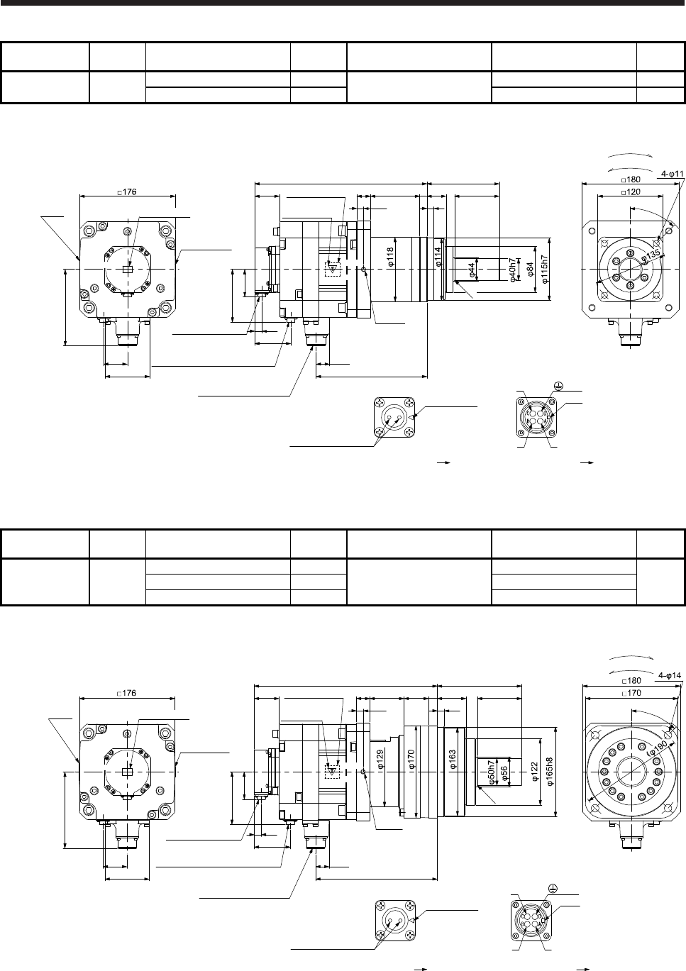
7. HG-SR SERIES
7 - 93
Model Output
[kW] Reducer model Reduction
ratio
Brake static friction torque
[N•m]
Moment of inertia J
[× 10-4 kg•m2]
Mass
[kg]
HG-SR202BG7
HG-SR2024BG7 2.0 HPG-32A-05-J2PBZI-S 1/5 44 61.4 26
HPG-32A-11-J2PBZJ-S 1/11 61.0 27
[Unit: mm]
Motor
plate
Caution plate
Bottom
Top Top
Bottom
317
45.5
Caution plate
Motor plate
(Opposite side)
24.8
203.8
50.9
13
Encoder connector
CMV1-R10P
Power supply connector
MS3102A22-22P
Bottom
Top
Bottom
Top
96.9
Electromagnetic brake connector
CMV1-R2P
66.5
44
U
W
V
Power supply connector
Motor flange direction
Key
Electromagnetic brake
Electromagnetic brake connector
Motor flange direction
25 91 13 35 82
133
12.5 13
140.9
Main key
position mark
For reverse rotation command
For forward rotation command
Rotation direction
82
45°
R0.4
BC41247*
(PE)
(Note)*
Caution plate
Note. * is a screw hole for eyebolt (M8).
Model Output
[kW] Reducer model Reduction
ratio
Brake static friction torque
[N•m]
Moment of inertia J
[× 10-4 kg•m2]
Mass
[kg]
HG-SR202BG7
HG-SR2024BG7 2.0
HPG-50A-21-J2BBDF-S 1/21
44
63.0
38
HPG-50A-33-J2BBDF-S 1/33 61.9
HPG-50A-45-J2BBDF-S 1/45 61.9
[Unit: mm]
Motor
plate Caution plate
Caution plate
Bottom
Top Top
Bottom
337
45.5 Motor plate
24.8
223.8
50.9
13
Encoder connector
CMV1-R10P
Power supply connector
MS3102A22-22P
Top
96.9
Electromagnetic brake connector
CMV1-R2P
66.5
44
U
W
V
Power supply connector
Motor flange direction
Key
Electromagnetic brake
Electromagnetic brake connector
Motor flange direction
25 63 45 16 53 82
156
12.5 13
R0.4
45°
140.9
Main key
position mark
For reverse rotation command
For forward rotation command
Rotation direction
82
BC41248*
(PE)
(Note)*
Bottom
(Opposite side)
Caution plate
Bottom
Top
Note. * is a screw hole for eyebolt (M8).
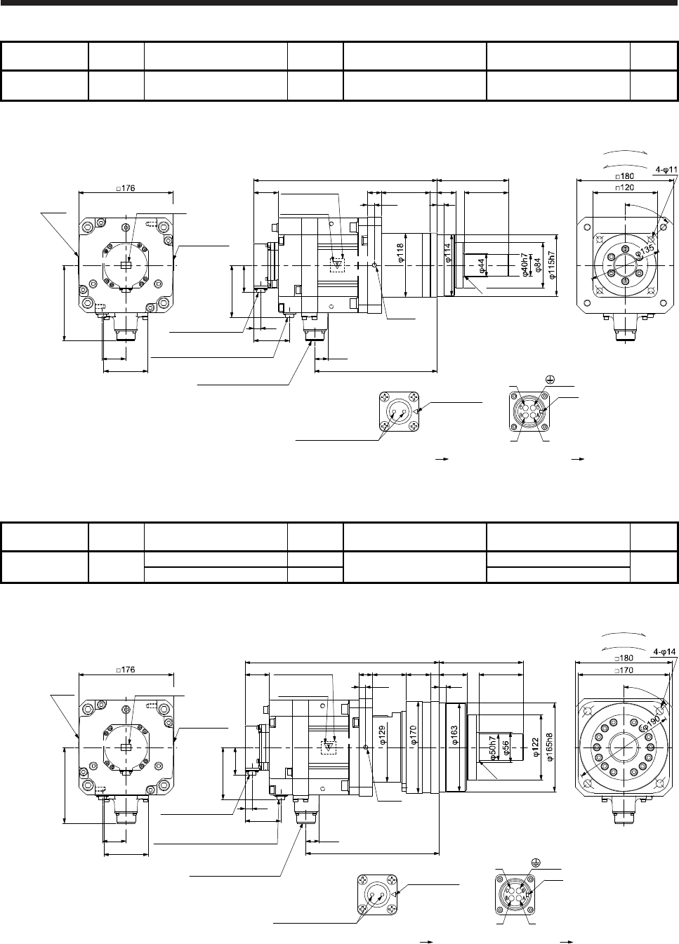
7. HG-SR SERIES
7 - 94
Model Output
[kW] Reducer model Reduction
ratio
Brake static friction torque
[N•m]
Moment of inertia J
[× 10-4 kg•m2]
Mass
[kg]
HG-SR352BG7
HG-SR3524BG7 3.5 HPG-32A-05-J2PBZI-S 1/5 44 93.1 31
[Unit: mm]
Motor
plate
Caution plate
Bottom
Top Top
Bottom
341
45.5
Caution plate
Motor plate
(Opposite side)
24.8
227.8
50.9
13
Encoder connector
CMV1-R10P
Power supply connector
MS3102A22-22P
Bottom
Top
96.9
Electromagnetic brake connector
CMV1-R2P
66.5
44
U
W
V
Power supply connector
Motor flange direction
Key
Electromagnetic brake
Electromagnetic brake connector
Motor flange direction
25 91 13 35 82
133
12.5 13
140.9
Main key
position mark
For reverse rotation command
For forward rotation command
Rotation direction
82
45°
R0.4
BC41249*
(PE)
(Note)*
Bottom
Top
Caution plate
Note. * is a screw hole for eyebolt (M8).
Model Output
[kW] Reducer model Reduction
ratio
Brake static friction torque
[N•m]
Moment of inertia J
[× 10-4 kg•m2]
Mass
[kg]
HG-SR352BG7
HG-SR3524BG7 3.5 HPG-50A-11-J2BBDF-S 1/11 44 96.6 43
HPG-50A-21-J2BBDF-S 1/21 94.7
[Unit: mm]
Motor
plate
Caution plate
Bottom
Top Top
Bottom
361
45.5
Caution plate
Motor plate
(Opposite side)
24.8
247.8
50.9
13
Encoder connector
CMV1-R10P
Power supply connector
MS3102A22-22P
Top
Top
96.9
Electromagnetic brake connector
CMV1-R2P
66.5
44
U
W
V
Power supply connector
Motor flange direction
Key
Electromagnetic brake
Electromagnetic brake connector
Motor flange direction
25 63 45 16 53 82
156
12.5 13
R0.4
45°
140.9
Main key
position mark
For reverse rotation command
For forward rotation command
Rotation direction
82
BC41250*
(PE)
(Note)*
Bottom
Bottom
Caution plate
Note. * is a screw hole for eyebolt (M8).
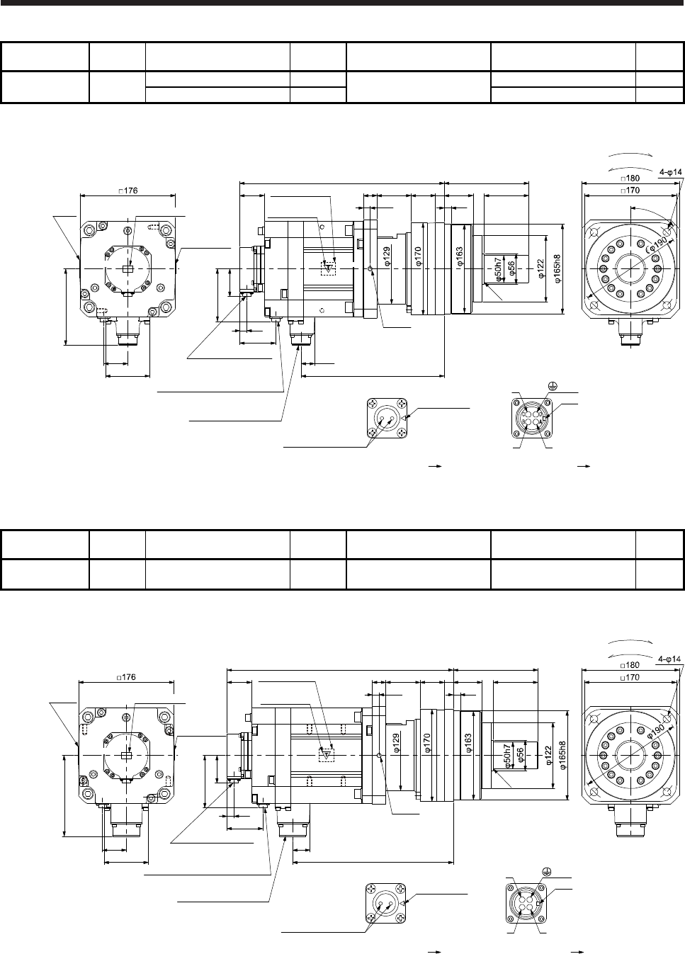
7. HG-SR SERIES
7 - 95
Model Output
[kW] Reducer model Reduction
ratio
Brake static friction torque
[N•m]
Moment of inertia J
[× 10-4 kg•m2]
Mass
[kg]
HG-SR502BG7
HG-SR5024BG7 5.0 HPG-50A-05-J2BBCF-S 1/5 44 121 45
HPG-50A-11-J2BBDF-S 1/11 117 47
[Unit: mm]
Motor
plate
Caution plate
Bottom
Top Top
Bottom
377
45.5
Caution plate
Motor plate
(Opposite side)
24.8
263.8
50.9
13
Encoder connector
CMV1-R10P
Power supply connector
MS3102A22-22P
Top
Top
96.9
Electromagnetic brake connector
CMV1-R2P
66.5
44
U
W
V
Power supply connector
Motor flange direction
Key
Electromagnetic brake
Electromagnetic brake connector
Motor flange direction
25 63 45 16 53 82
156
12.5 13
R0.4
45°
140.9
Main key
position mark
For reverse rotation command
For forward rotation command
Rotation direction
82
BC41251*
(PE)
(Note)*
Caution plate
Bottom Bottom
Note. * is a screw hole for eyebolt (M8).
Model Output
[kW] Reducer model Reduction
ratio
Brake static friction torque
[N•m]
Moment of inertia J
[× 10-4 kg•m2]
Mass
[kg]
HG-SR702BG7
HG-SR7024BG7 7.0 HPG-50A-05-J2BBCF-S 1/5 44 173 52
[Unit: mm]
AB
CD
Motor
plate
Caution plate
Bottom
Top Top
Bottom
417
45.5
Caution plate
Motor plate
(Opposite side)
32
295.8
50.9
13
Bottom
Top
Top
96.9
66.5
44
U
W
V
Power supply connector
Motor flange direction
Key
Electromagnetic brake
Electromagnetic brake connector
Motor flange direction
25 63 45 16 53 82
156
12.5 13
R0.4
149.1
Main key
position mark
For reverse rotation command
For forward rotation command
Rotation direction
82
BC41252*
(PE)
(Note)*
Encoder connector
CMV1-R10P
Power supply connector
MS3102A32-17P
Electromagnetic brake connector
CMV1-R2P
Bottom
Caution plate
Note. * is a screw hole for eyebolt (M8).

7. HG-SR SERIES
7 - 96
MEMO
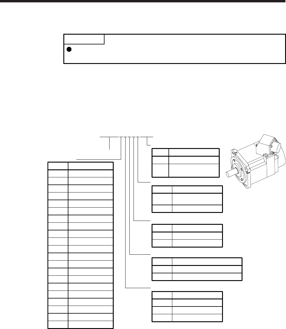
8. HG-JR SERIES
8 - 1
8. HG-JR SERIES
POINT
The 1500 r/min series servo motor of 22 kW or more and 1000 r/min series
servo motor of 15 kW or more with an electromagnetic brake are not available.
This chapter provides information on the servo motor specifications and characteristics. When using the HG-
JR series servo motor, always read the Safety Instructions in the beginning of this manual and chapters 1 to
5, in addition to this chapter.
8.1 Model designation
The following describes model designation. Not all combinations of the symbols are available.
None None
Electromagnetic brake
Symbol Electromagnetic brake
BWith
Series
Shaft type
Symbol Shaft shape
None Standard
(straight shaft)
K (Note 1) Keyway shaft
Appearance
50.5
Rated output
Symbol Rated output [kW]
70.75
10 1
15 1.5
20 2
35 3.5
50 5
25K 25
30K 30
Power supply voltage of servo amplifier
Rated speed
1M 1500
Symbol Speed [r/min]
3 3000
None 3-phase 200 V AC to 240 V AC
Symbol Voltage
4 3-phase 380 V AC to 480 V AC
37K 37
45K 45
5555K
HG-JR534BK
1 1000
60 6
70 7
80 8
90 9
11K 11
12K 12
15K 15
20K 20
22K 22
W0C
None Standard
Special specification
Symbol Special specification
(Note 2)
W0C Servo motor with
functional safety
Note 1. Key is not included.
2. Refer to section 1.5 for details.
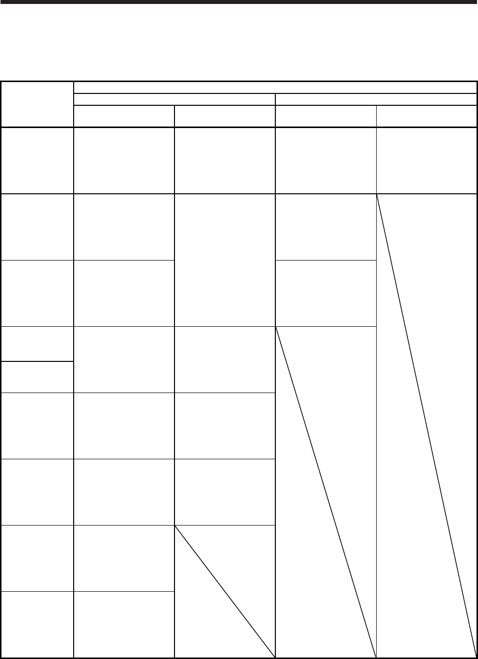
8. HG-JR SERIES
8 - 2
8.2 Combination list of servo motors and servo amplifiers/drive units
(1) Compatible with 3-phase 200 V AC
(a) 3000 r/min series
Servo motor
Servo amplifier
MR-J4 1-axis MR-J4 2-axis
Standard When the maximum
torque is 400% (Note) Standard When the maximum
torque is 400% (Note)
HG-JR53
MR-J4-60A
MR-J4-60A-RJ
MR-J4-60B
MR-J4-60B-RJ
MR-J4-60B-RJ010
MR-J4-60B-RJ020
MR-J4-100A
MR-J4-100A-RJ
MR-J4-100B
MR-J4-100B-RJ
MR-J4-100B-RJ010
MR-J4-100B-RJ020
MR-J4W2-77B MR-J4W2-1010B
HG-JR73
MR-J4-70A
MR-J4-70A-RJ
MR-J4-70B
MR-J4-70B-RJ
MR-J4-70B-RJ010
MR-J4-70B-RJ020
MR-J4-200A
MR-J4-200A-RJ
MR-J4-200B
MR-J4-200B-RJ
MR-J4-200B-RJ010
MR-J4-200B-RJ020
MR-J4W2-77B
MR-J4W2-1010B
HG-JR103
MR-J4-100A
MR-J4-100A-RJ
MR-J4-100B
MR-J4-100B-RJ
MR-J4-100B-RJ010
MR-J4-100B-RJ020
MR-J4W2-1010B
HG-JR153
MR-J4-200A
MR-J4-200A-RJ
MR-J4-200B
MR-J4-200B-RJ
MR-J4-200B-RJ010
MR-J4-200B-RJ020
MR-J4-350A
MR-J4-350A-RJ
MR-J4-350B
MR-J4-350B-RJ
MR-J4-350B-RJ010
MR-J4-350B-RJ020
HG-JR203
HG-JR353
MR-J4-350A
MR-J4-350A-RJ
MR-J4-350B
MR-J4-350B-RJ
MR-J4-350B-RJ010
MR-J4-350B-RJ020
MR-J4-500A
MR-J4-500A-RJ
MR-J4-500B
MR-J4-500B-RJ
MR-J4-500B-RJ010
MR-J4-500B-RJ020
HG-JR503
MR-J4-500A
MR-J4-500A-RJ
MR-J4-500B
MR-J4-500B-RJ
MR-J4-500B-RJ010
MR-J4-500B-RJ020
MR-J4-700A
MR-J4-700A-RJ
MR-J4-700B
MR-J4-700B-RJ
MR-J4-700B-RJ010
MR-J4-700B-RJ020
HG-JR703
MR-J4-700A
MR-J4-700A-RJ
MR-J4-700B
MR-J4-700B-RJ
MR-J4-700B-RJ010
MR-J4-700B-RJ020
HG-JR903
MR-J4-11KA
MR-J4-11KA-RJ
MR-J4-11KB
MR-J4-11KB-RJ
MR-J4-11KB-RJ010
MR-J4-11KB-RJ020
Note. The maximum torque can be increased to 400% by changing the servo amplifier.
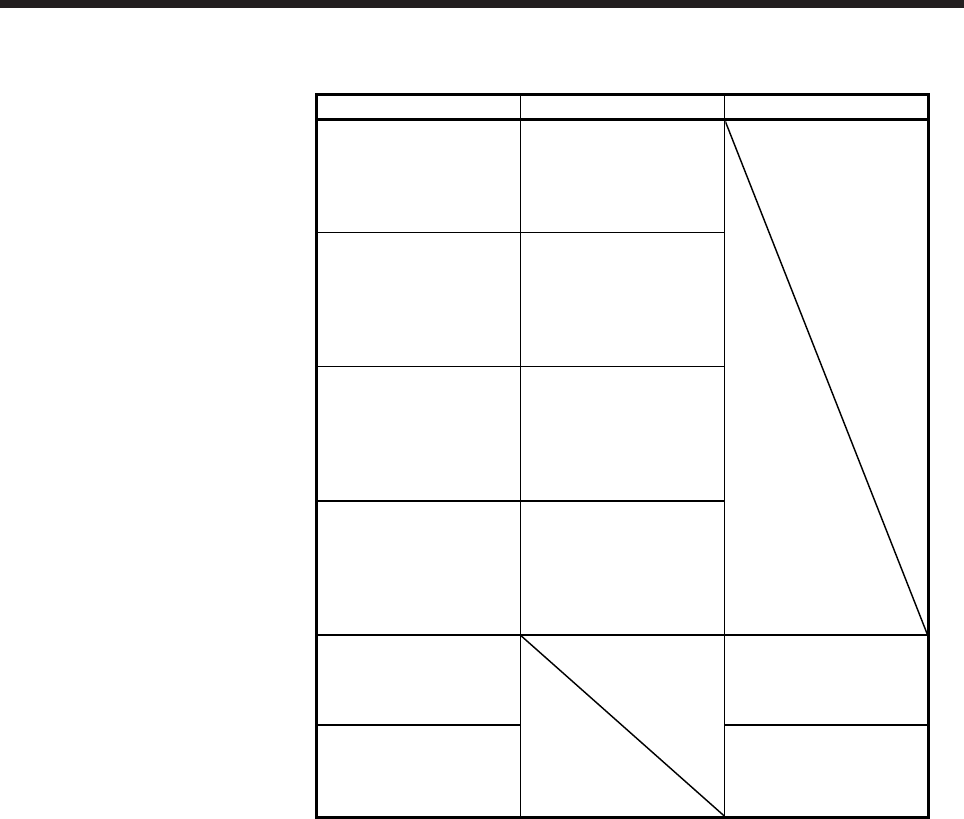
8. HG-JR SERIES
8 - 3
(b) 1500 r/min series
Servo motor Servo amplifier Drive unit
HG-JR701M
MR-J4-700A
MR-J4-700A-RJ
MR-J4-700B
MR-J4-700B-RJ
MR-J4-700B-RJ010
HG-JR11K1M
MR-J4-11KA
MR-J4-11KA-RJ
MR-J4-11KB
MR-J4-11KB-RJ
MR-J4-11KB-RJ010
MR-J4-11KB-RJ020
HG-JR15K1M
MR-J4-15KA
MR-J4-15KA-RJ
MR-J4-15KB
MR-J4-15KB-RJ
MR-J4-15KB-RJ010
MR-J4-15KB-RJ020
HG-JR22K1M
MR-J4-22KA
MR-J4-22KA-RJ
MR-J4-22KB
MR-J4-22KB-RJ
MR-J4-22KB-RJ010
MR-J4-22KB-RJ020
HG-JR30K1M
MR-J4-DU30KA
MR-J4-DU30KA-RJ
MR-J4-DU30KB
MR-J4-DU30KB-RJ
HG-JR37K1M
MR-J4-DU37KA
MR-J4-DU37KA-RJ
MR-J4-DU37KB
MR-J4-DU37KB-RJ

8. HG-JR SERIES
8 - 4
(c) 1000 r/min series
Servo motor Servo amplifier Drive unit
HG-JR601
MR-J4-700A
MR-J4-700A-RJ
MR-J4-700B
MR-J4-700B-RJ
MR-J4-700B-RJ010
HG-JR801 MR-J4-11KA
MR-J4-11KA-RJ
MR-J4-11KB
MR-J4-11KB-RJ
MR-J4-11KB-RJ010
HG-JR12K1
HG-JR15K1
MR-J4-15KA
MR-J4-15KA-RJ
MR-J4-15KB
MR-J4-15KB-RJ
MR-J4-15KB-RJ010
HG-JR20K1
MR-J4-22KA
MR-J4-22KA-RJ
MR-J4-22KB
MR-J4-22KB-RJ
MR-J4-22KB-RJ010
MR-J4-22KB-RJ020
HG-JR25K1
HG-JR30K1
MR-J4-DU30KA
MR-J4-DU30KA-RJ
MR-J4-DU30KB
MR-J4-DU30KB-RJ
HG-JR37K1
MR-J4-DU37KA
MR-J4-DU37KA-RJ
MR-J4-DU37KB
MR-J4-DU37KB-RJ

8. HG-JR SERIES
8 - 5
(2) Compatible with 3-phase 400 V AC
(a) 3000 r/min series
Servo motor
Servo amplifier
Servo motor Servo amplifier
Standard When the maximum torque
is 400% (Note)
MR-J4-60A4 MR-J4-100A4 MR-J4-700A4
MR-J4-60A4-RJ MR-J4-100A4-RJ MR-J4-700A4-RJ
HG-JR534 MR-J4-60B4 MR-J4-100B4
HG-JR7034 MR-J4-700B4
MR-J4-60B4-RJ MR-J4-100B4-RJ MR-J4-700B4-RJ
MR-J4-60B4-RJ010 MR-J4-100B4-RJ010 MR-J4-700B4-RJ010
MR-J4-60B4-RJ020 MR-J4-100B4-RJ020 MR-J4-700B4-RJ020
MR-J4-100A4 MR-J4-200A4 MR-J4-11KA4
HG-JR734 MR-J4-100A4-RJ MR-J4-200A4-RJ MR-J4-11KA4-RJ
MR-J4-100B4 MR-J4-200B4
HG-JR9034 MR-J4-11KB4
MR-J4-100B4-RJ MR-J4-200B4-RJ MR-J4-11KB4-RJ
HG-JR1034 MR-J4-100B4-RJ010 MR-J4-200B4-RJ010 MR-J4-11KB4-RJ010
MR-J4-100B4-RJ020 MR-J4-200B4-RJ020 MR-J4-11KB4-RJ020
MR-J4-200A4 MR-J4-350A4
HG-JR1534 MR-J4-200A4-RJ MR-J4-350A4-RJ
MR-J4-200B4 MR-J4-350B4
MR-J4-200B4-RJ MR-J4-350B4-RJ
HG-JR2034 MR-J4-200B4-RJ010 MR-J4-350B4-RJ010
MR-J4-200B4-RJ020 MR-J4-350B4-RJ020
MR-J4-350A4 MR-J4-500A4
MR-J4-350A4-RJ MR-J4-500A4-RJ
HG-JR3534 MR-J4-350B4 MR-J4-500B4
MR-J4-350B4-RJ MR-J4-500B4-RJ
MR-J4-350B4-RJ010 MR-J4-500B4-RJ010
MR-J4-350B4-RJ020 MR-J4-500B4-RJ020
MR-J4-500A4 MR-J4-700A4
MR-J4-500A4-RJ MR-J4-700A4-RJ
HG-JR5034 MR-J4-500B4 MR-J4-700B4
MR-J4-500B4-RJ MR-J4-700B4-RJ
MR-J4-500B4-RJ010 MR-J4-700B4-RJ010
MR-J4-500B4-RJ020 MR-J4-700B4-RJ020
Note. The maximum torque can be increased to 400% by changing the servo amplifier.
8. HG-JR SERIES
8 - 6
(b) 1500 r/min series
Servo motor Servo amplifier Drive unit
HG-JR701M4
MR-J4-700A4
MR-J4-700A4-RJ
MR-J4-700B4
MR-J4-700B4-RJ
MR-J4-700B4-RJ010
HG-JR11K1M4
MR-J4-11KA4
MR-J4-11KA4-RJ
MR-J4-11KB4
MR-J4-11KB4-RJ
MR-J4-11KB4-RJ010
MR-J4-11KB4-RJ020
HG-JR15K1M4
MR-J4-15KA4
MR-J4-15KA4-RJ
MR-J4-15KB4
MR-J4-15KB4-RJ
MR-J4-15KB4-RJ010
MR-J4-15KB4-RJ020
HG-JR22K1M4
MR-J4-22KA4
MR-J4-22KA4-RJ
MR-J4-22KB4
MR-J4-22KB4-RJ
MR-J4-22KB4-RJ010
MR-J4-22KB4-RJ020
HG-JR30K1M4
MR-J4-DU30KA4
MR-J4-DU30KA4-RJ
MR-J4-DU30KB4
MR-J4-DU30KB4-RJ
HG-JR37K1M4
MR-J4-DU37KA4
MR-J4-DU37KA4-RJ
MR-J4-DU37KB4
MR-J4-DU37KB4-RJ
HG-JR45K1M4
MR-J4-DU45KA4
MR-J4-DU45KA4-RJ
MR-J4-DU45KB4
MR-J4-DU45KB4-RJ
HG-JR55K1M4
MR-J4-DU55KA4
MR-J4-DU55KA4-RJ
MR-J4-DU55KB4
MR-J4-DU55KB4-RJ

8. HG-JR SERIES
8 - 7
(c) 1000 r/min series
Servo motor Servo amplifier Drive unit
HG-JR6014
MR-J4-700A4
MR-J4-700A4-RJ
MR-J4-700B4
MR-J4-700B4-RJ
MR-J4-700B4-RJ010
HG-JR8014 MR-J4-11KA4
MR-J4-11KA4-RJ
MR-J4-11KB4
MR-J4-11KB4-RJ
MR-J4-11KB4-RJ010
HG-JR12K14
HG-JR15K14
MR-J4-15KA4
MR-J4-15KA4-RJ
MR-J4-15KB4
MR-J4-15KB4-RJ
MR-J4-15KB4-RJ010
HG-JR20K14 MR-J4-22KA4
MR-J4-22KA4-RJ
MR-J4-22KB4
MR-J4-22KB4-RJ
MR-J4-22KB4-RJ010
HG-JR25K14
HG-JR30K14
MR-J4-DU30KA4
MR-J4-DU30KA4-RJ
MR-J4-DU30KB4
MR-J4-DU30KB4-RJ
HG-JR37K14
MR-J4-DU37KA4
MR-J4-DU37KA4-RJ
MR-J4-DU37KB4
MR-J4-DU37KB4-RJ
8. HG-JR SERIES
8 - 8
8.3 Standard specifications
8.3.1 Standard specifications list
Servo motor
Item
HG-JR 3000 r/min series
(Compatible with 3-phase 200 V AC, low inertia/medium capacity)
53(B) 73(B) 103(B) 153(B) 203(B) 353(B) 503(B) 703(B) 903(B)
Power supply capacity Refer to "Power supply equipment capacity and generated loss of servo amplifiers"
in Servo Amplifier Instruction Manual.
Continuous running
duty (Note 1)
Rated output
(Note 8) [kW] 0.5 0.75 1.0 1.5 2.0 3.3
(3.5) 5.0 7.0 9.0
Rated torque
(Note 8) [N•m] 1.6 2.4 3.2 4.8 6.4
10.5
(11.1) 15.9 22.3 28.6
Maximum torque (Note 8) [N•m] 4.8
(6.4)
7.2
(9.6)
9.6
(12.7)
14.3
(19.1)
19.1
(25.5)
32.0
(44.6)
47.7
(63.7) 66.8 85.8
Rated speed (Note 1) [r/min] 3000
Maximum speed [r/min] 6000 5000
Instantaneous permissible speed [r/min] 6900 5750
Power rate at
continuous rated
torque
Standard [kW/s] 16.7 27.3 38.2 60.2 82.4 83.5 133 115 147
With an
electromagnetic brake
[kW/s]
12.5 22.0 32.2 53.1 74.8 71.6 119 93.9 125
Rated current (Note 8) [A] 3.0 5.6 5.6 11 11 17
(18) 27 34 41
Maximum current (Note 8) [A] 9.0
(12)
17
(23)
17
(23)
32
(43)
32
(43)
51
(71)
81
(108) 103 134
Moment of inertia J
Standard [× 10-4 kg•m2] 1.52 2.09 2.65 3.79 4.92 13.2 19.0 43.3 55.8
With an
electromagnetic brake
[× 10-4 kg•m2]
2.02 2.59 3.15 4.29 5.42 15.4 21.2 52.9 65.4
Recommended load to motor inertia ratio
(Note 2) 10 times or less
Speed/position detector 22-bit encoder common to absolute position/incremental
(resolution per servo motor revolution: 4194304 pulses/rev)
Oil seal With
Insulation class 155 (F)
Structure Totally-enclosed, natural-cooling (IP rating: IP67 (Note 3))
Environment (Note 4)
Ambient
temperature
Operation 0 ˚C to 40 ˚C (non-freezing)
Storage -15 ˚C to 70 ˚C (non-freezing)
Ambient
humidity
Operation 80 %RH or less (non-condensing)
Storage 90 %RH or less (non-condensing)
Ambience Indoors (no direct sunlight),
free from corrosive gas, flammable gas, oil mist, dust, and dirt
Altitude 1000 m or less above sea level
Vibration resistance
(Note 5) X, Y: 24.5 m/s2
X: 24.5 m/s2
Y: 29.4 m/s2
Vibration rank (Note 6) V10
Permissible load for
the shaft (Note 7)
L [mm] 40 55 79
Radial [N] 323 980 2450
Thrust [N] 284 490 980
Mass
Standard [kg] 3.0 3.7 4.5 5.9 7.5 13 18 29 36
With an
electromagnetic brake
[kg]
4.4 5.1 5.9 7.3 8.9 15 20 35 42
8. HG-JR SERIES
8 - 9
Servo motor
Item
HG-JR 1500 r/min series
(Compatible with 3-phase 200 V AC, low inertia/large capacity)
701M(B) 11K1M(B) 15K1M(B) 22K1M 30K1M 37K1M
Power supply capacity Refer to "Power supply equipment capacity and generated loss of servo amplifiers"
in Servo Amplifier Instruction Manual.
Continuous running
duty (Note 1)
Rated output [kW] 7.0 11 15 22 30 37
Rated torque [N•m] 44.6 70.0 95.5 140 191 236
Maximum torque [N•m] 134 210 286 420 573 707
Rated speed (Note 1) [r/min] 1500
Maximum speed [r/min] 3000 2500
Instantaneous permissible speed [r/min] 3450 2875
Power rate at
continuous rated
torque
Standard [kW/s] 113 223 289 401 582 726
With an
electromagnetic brake
[kW/s]
101 204 271
Rated current [A] 34 61 76 99 139 151
Maximum current [A] 111 200 246 315 479 561
Moment of inertia J
Standard [× 10-4 kg•m2] 176 220 315 489 627 764
With an
electromagnetic brake
[× 10-4 kg•m2]
196 240 336
Recommended load to motor inertia ratio
(Note 2) 10 times or less
Speed/position detector 22-bit encoder common to absolute position/incremental
(resolution per servo motor revolution: 4194304 pulses/rev)
Oil seal With
Insulation class 155 (F)
Structure
Totally-enclosed, natural-cooling
(IP rating: IP67 (Note 3))
Totally-enclosed, force-cooled
(IP rating: IP44 (Note 3))
Environment (Note 4)
Ambient
temperature
Operation 0 °C to 40 °C (non-freezing)
Storage -15 °C to 70 °C (non-freezing)
Ambient
humidity
Operation 80 %RH or less (non-condensing)
Storage 90 %RH or less (non-condensing)
Ambience Indoors (no direct sunlight),
free from corrosive gas, flammable gas, oil mist, dust, and dirt
Altitude 1000 m or less above sea level
Vibration resistance
(Note 5) X, Y: 24.5 m/s2
Vibration rank (Note 6) V10
Permissible load for
the shaft (Note 7)
L [mm] 85 116 140
Radial [N] 2450 2940 3234
Thrust [N] 980 1470
Mass
Standard [kg] 53 62 86 120 145 165
With an
electromagnetic brake
[kg]
65 74 97
Cooling fan
Power
supply
Voltage/
Frequency
3-phase 200 V AC to 240 V AC
50 Hz/60 Hz
Power
consumption
[W]
65 (50 Hz)/85 (60 Hz)
Rated current [A] 0.20 (50 Hz)/0.22 (60 Hz)
8. HG-JR SERIES
8 - 10
Servo motor
Item
HG-JR 1000 r/min series
(Compatible with 3-phase 200 V AC, low inertia/large capacity)
601(B) 801(B) 12K1(B) 15K1 20K1 25K1 30K1 37K1
Power supply capacity Refer to "Power supply equipment capacity and generated loss of servo amplifiers"
in Servo Amplifier Instruction Manual.
Continuous running
duty (Note 1)
Rated output [kW] 6.0 8.0 12 15 20 25 30 37
Rated torque [N•m] 57.3 76.4 115 143 191 239 286 353
Maximum torque [N•m] 172 229 345 429 573 717 858 1059
Rated speed (Note 1) [r/min] 1000
Maximum speed [r/min] 2000 1500
Instantaneous permissible speed [r/min] 2300 1725
Power rate at
continuous rated
torque
Standard [kW/s] 187 265 420 418 582 748 594 761
With an
electromagnetic brake
[kW/s]
167 243 394
Rated current [A] 31 47 60 67 94 95 121 152
Maximum current [A] 108 165 208 231 318 313 399 495
Moment of inertia J
Standard [× 10-4 kg•m2] 176 220 315 489 627 764 1377 1637
With an
electromagnetic brake
[× 10-4 kg•m2]
196 240 336
Recommended load to motor inertia ratio
(Note 2) 10 times or less
Speed/position detector 22-bit encoder common to absolute position/incremental
(resolution per servo motor revolution: 4194304 pulses/rev)
Oil seal With
Insulation class 155 (F)
Structure
Totally-enclosed,
natural-cooling
(IP rating: IP67 (Note 3))
Totally-enclosed, force-cooled
(IP rating: IP44 (Note 3))
Environment (Note 4)
Ambient
temperature
Operation 0 °C to 40 °C (non-freezing)
Storage -15 °C to 70 °C (non-freezing)
Ambient
humidity
Operation 80 %RH or less (non-condensing)
Storage 90 %RH or less (non-condensing)
Ambience Indoors (no direct sunlight),
free from corrosive gas, flammable gas, oil mist, dust, and dirt
Altitude 1000 m or less above sea level
Vibration resistance
(Note 5) X, Y: 24.5 m/s2 X, Y: 9.8 m/s2
Vibration rank (Note 6) V10
Permissible load for
the shaft (Note 7)
L [mm] 85 116 140 140
Radial [N] 2450 2940 3234 4900
Thrust [N] 980 1470 1960
Mass
Standard [kg] 53 62 86 120 145 165 215 240
With an
electromagnetic brake
[kg]
65 74 97
Cooling fan
Power
supply
Voltage/
Frequency 3-phase 200 V AC to 240 V AC, 50 Hz/60 Hz
Power
consumption
[W]
65 (50 Hz)/85 (60 Hz) 120 (50 Hz)/
175 (60 Hz)
Rated current [A] 0.20 (50 Hz)/0.22 (60 Hz) 0.39 (50 Hz)/
0.52 (60 Hz)
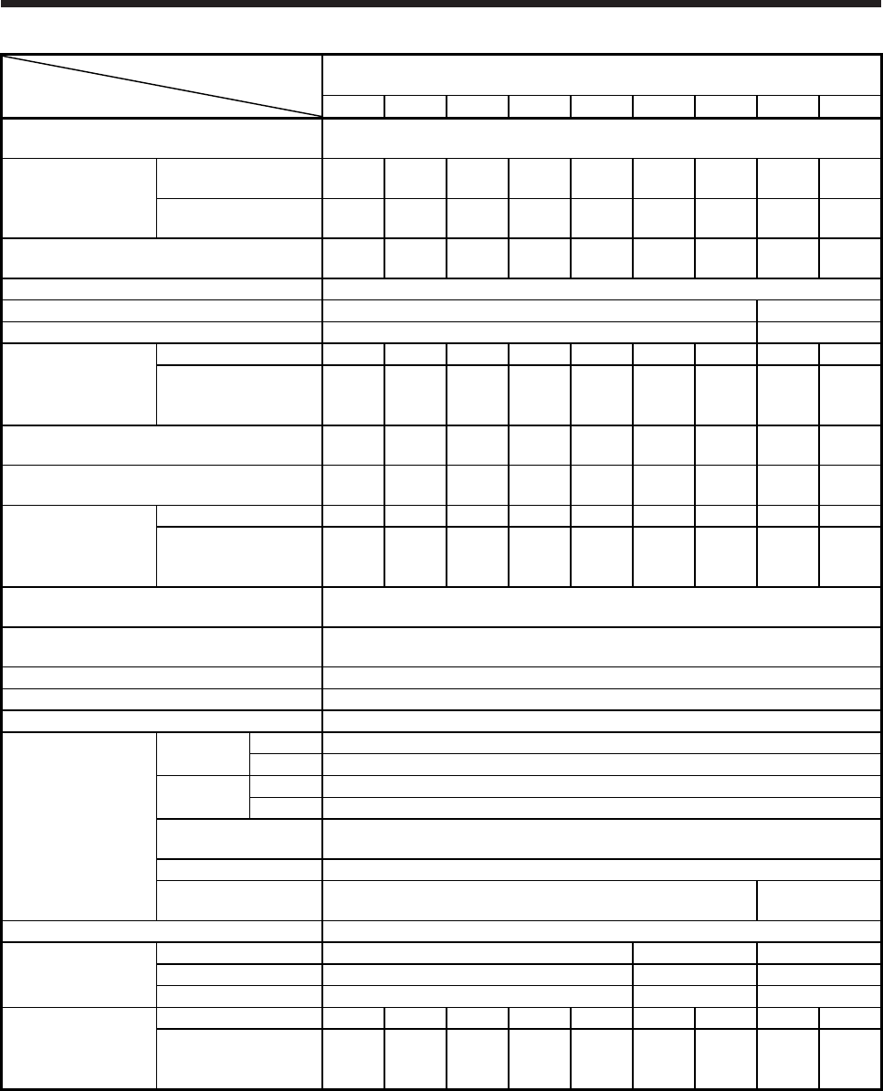
8. HG-JR SERIES
8 - 11
Servo motor
Item
HG-JR 3000 r/min series
(Compatible with 3-phase 400 V AC, low inertia/medium capacity)
534(B) 734(B) 1034(B) 1534(B) 2034(B) 3534(B) 5034(B) 7034(B) 9034(B)
Power supply capacity Refer to "Power supply equipment capacity and generated loss of servo amplifiers"
in Servo Amplifier Instruction Manual.
Continuous running
duty (Note 1)
Rated output
(Note 8) [kW] 0.5 0.75 1.0 1.5 2.0 3.3
(3.5) 5.0 7.0 9.0
Rated torque
(Note 8) [N•m] 1.6 2.4 3.2 4.8 6.4
10.5
(11.1) 15.9 22.3 28.6
Maximum torque (Note 8) [N•m] 4.8
(6.4)
7.2
(9.6)
9.6
(12.7)
14.3
(19.1)
19.1
(25.5)
32.0
(44.6)
47.7
(63.7) 66.8 85.8
Rated speed (Note 1) [r/min] 3000
Maximum speed [r/min] 6000 5000
Instantaneous permissible speed [r/min] 6900 5750
Power rate at
continuous rated
torque
Standard [kW/s] 16.7 27.3 38.2 60.2 82.4 83.5 133 115 147
With an
electromagnetic brake
[kW/s]
12.5 22.0 32.2 53.1 74.8 71.6 119 93.9 125
Rated current (Note 8) [A] 1.5 2.8 2.8 5.4 5.4 8.3
(8.8) 14 17 21
Maximum current (Note 8) [A] 4.5
(6.0)
8.4
(12)
8.4
(12)
17
(22)
17
(22)
26
(36)
41
(54) 52 67
Moment of inertia J
Standard [× 10-4 kg•m2] 1.52 2.09 2.65 3.79 4.92 13.2 19.0 43.3 55.8
With an
electromagnetic brake
[× 10-4 kg•m2]
2.02 2.59 3.15 4.29 5.42 15.4 21.2 52.9 65.4
Recommended load to motor inertia ratio
(Note 2) 10 times or less
Speed/position detector 22-bit encoder common to absolute position/incremental
(resolution per servo motor revolution: 4194304 pulses/rev)
Oil seal With
Insulation class 155 (F)
Structure Totally-enclosed, natural-cooling (IP rating: IP67 (Note 3))
Environment (Note 4)
Ambient
temperature
Operation 0 ˚C to 40 ˚C (non-freezing)
Storage -15 ˚C to 70 ˚C (non-freezing)
Ambient
humidity
Operation 80 %RH or less (non-condensing)
Storage 90 %RH or less (non-condensing)
Ambience Indoors (no direct sunlight),
free from corrosive gas, flammable gas, oil mist, dust, and dirt
Altitude 1000 m or less above sea level
Vibration resistance
(Note 5) X, Y: 24.5 m/s2
X: 24.5 m/s2
Y: 29.4 m/s2
Vibration rank (Note 6) V10
Permissible load for
the shaft (Note 7)
L [mm] 40 55 79
Radial [N] 323 980 2450
Thrust [N] 284 490 980
Mass
Standard [kg] 3.0 3.7 4.5 5.9 7.5 13 18 29 36
With an
electromagnetic brake
[kg]
4.4 5.1 5.9 7.3 8.9 15 20 35 42
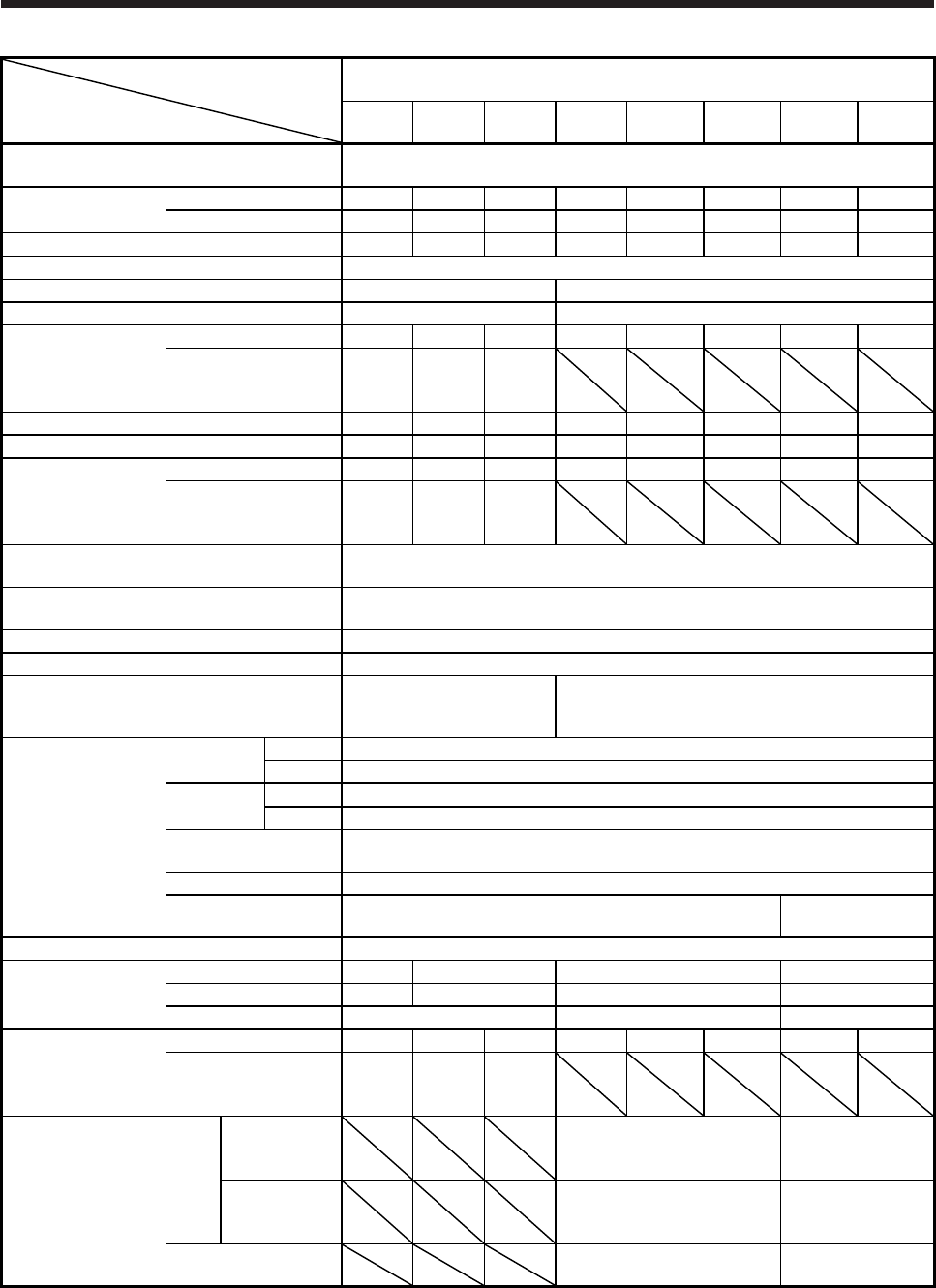
8. HG-JR SERIES
8 - 12
Servo motor
Item
HG-JR 1500 r/min series
(Compatible with 3-phase 400 V AC, low inertia/large capacity)
701M4
(B)
11K1M4
(B)
15K1M4
(B) 22K1M4 30K1M4 37K1M4 45K1M4 55K1M4
Power supply capacity Refer to "Power supply equipment capacity and generated loss of servo amplifiers"
in Servo Amplifier Instruction Manual.
Continuous running
duty (Note 1)
Rated output [kW] 7.0 11 15 22 30 37 45 55
Rated torque [N•m] 44.6 70.0 95.5 140 191 236 286 350
Maximum torque [N•m] 134 210 286 420 573 707 859 1050
Rated speed (Note 1) [r/min] 1500
Maximum speed [r/min] 3000 2500
Instantaneous permissible speed [r/min] 3450 2875
Power rate at
continuous rated
torque
Standard [kW/s] 113 223 289 401 582 726 596 749
With an
electromagnetic brake
[kW/s]
101 204 271
Rated current [A] 17 31 38 50 68 79 85 110
Maximum current [A] 56 100 123 170 235 263 288 357
Moment of inertia J
Standard [× 10-4 kg•m2] 176 220 315 489 627 764 1377 1637
With an
electromagnetic brake
[× 10-4 kg•m2]
196 240 336
Recommended load to motor inertia ratio
(Note 2) 10 times or less
Speed/position detector 22-bit encoder common to absolute position/incremental
(resolution per servo motor revolution: 4194304 pulses/rev)
Oil seal With
Insulation class 155 (F)
Structure
Totally-enclosed,
natural-cooling
(IP rating: IP67 (Note 3))
Totally-enclosed, force-cooling
(IP rating: IP44 (Note 3))
Environment (Note 4)
Ambient
temperature
Operation 0 ˚C to 40 ˚C (non-freezing)
Storage -15 ˚C to 70 ˚C (non-freezing)
Ambient
humidity
Operation 80 %RH or less (non-condensing)
Storage 90 %RH or less (non-condensing)
Ambience Indoors (no direct sunlight),
free from corrosive gas, flammable gas, oil mist, dust, and dirt
Altitude 1000 m or less above sea level
Vibration resistance
(Note 5) X, Y: 24.5 m/s2 X, Y: 9.8 m/s2
Vibration rank (Note 6) V10
Permissible load for
the shaft (Note 7)
L [mm] 85 116 140 140
Radial [N] 2450 2940 3234 4900
Thrust [N] 980 1470 1960
Mass
Standard [kg] 53 62 86 120 145 165 215 240
With an
electromagnetic brake
[kg]
65 74 97
Cooling fan
Power
supply
Voltage/
Frequency
3-phase 380 V AC to
480 V AC
50 Hz/60 Hz
3-phase 380 V AC
to 460 V AC
50 Hz/60 Hz
Power
consumption
[W]
65 (50 Hz)/85 (60 Hz) 110 (50 Hz)/
150 (60 Hz)
Rated current [A] 0.12 (50 Hz)/0.14 (60 Hz) 0.20 (50 Hz)/
0.22 (60 Hz)
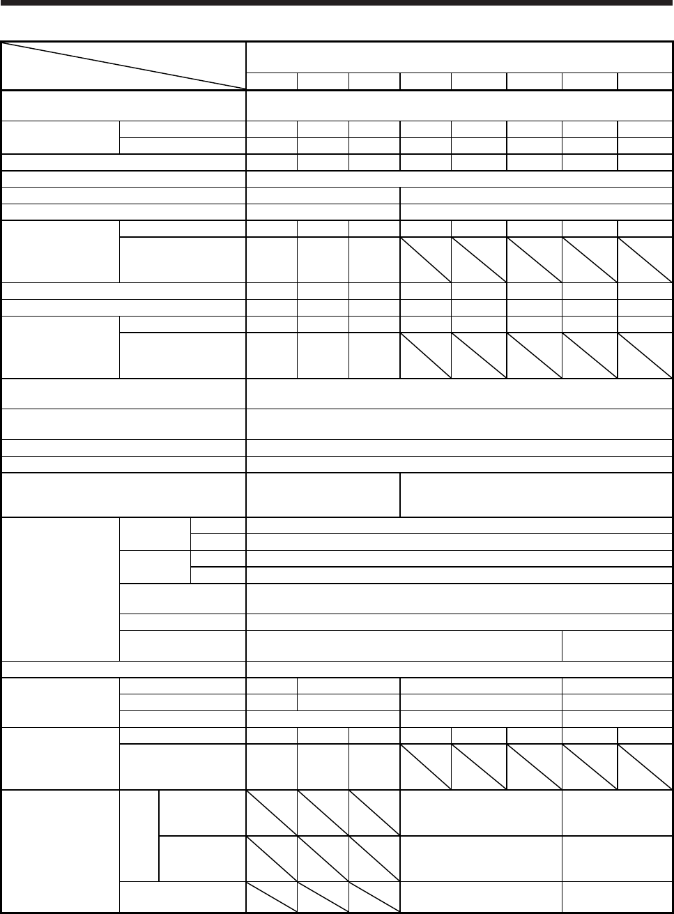
8. HG-JR SERIES
8 - 13
Servo motor
Item
HG-JR 1000 r/min series
(Compatible with 3-phase 400 V AC, low inertia/large capacity)
6014(B) 8014(B) 12K14(B) 15K14 20K14 25K14 30K14 37K14
Power supply capacity Refer to "Power supply equipment capacity and generated loss of servo amplifiers"
in Servo Amplifier Instruction Manual.
Continuous running
duty (Note 1)
Rated output [kW] 6.0 8.0 12 15 20 25 30 37
Rated torque [N•m] 57.3 76.4 115 143 191 239 286 353
Maximum torque [N•m] 172 229 345 429 573 717 858 1059
Rated speed (Note 1) [r/min] 1000
Maximum speed [r/min] 2000 1500
Instantaneous permissible speed [r/min] 2300 1725
Power rate at
continuous rated
torque
Standard [kW/s] 187 265 420 418 582 748 594 761
With an
electromagnetic brake
[kW/s]
167 243 394
Rated current [A] 16 23 30 33 47 48 60 76
Maximum current [A] 54 80 104 114 161 160 202 248
Moment of inertia J
Standard [× 10-4 kg•m2] 176 220 315 489 627 764 1377 1637
With an
electromagnetic brake
[× 10-4 kg•m2]
196 240 336
Recommended load to motor inertia ratio
(Note 2) 10 times or less
Speed/position detector 22-bit encoder common to absolute position/incremental
(resolution per servo motor revolution: 4194304 pulses/rev)
Oil seal With
Insulation class 155 (F)
Structure
Totally-enclosed,
natural-cooling
(IP rating: IP67 (Note 3))
Totally-enclosed, force-cooling
(IP rating: IP44 (Note 3))
Environment (Note 4)
Ambient
temperature
Operation 0 ˚C to 40 ˚C (non-freezing)
Storage -15 ˚C to 70 ˚C (non-freezing)
Ambient
humidity
Operation 80 %RH or less (non-condensing)
Storage 90 %RH or less (non-condensing)
Ambience Indoors (no direct sunlight),
free from corrosive gas, flammable gas, oil mist, dust, and dirt
Altitude 1000 m or less above sea level
Vibration resistance
(Note 5) X, Y: 24.5 m/s2 X, Y: 9.8 m/s2
Vibration rank (Note 6) V10
Permissible load for
the shaft (Note 7)
L [mm] 85 116 140 140
Radial [N] 2450 2940 3234 4900
Thrust [N] 980 1470 1960
Mass
Standard [kg] 53 62 86 120 145 165 215 240
With an
electromagnetic brake
[kg]
65 74 97
Cooling fan
Power
supply
Voltage/
Frequency
3-phase 380 V AC to
480 V AC
50 Hz/60 Hz
3-phase 380 V AC
to 460 V AC
50 Hz/60 Hz
Power
consumption
[W]
65 (50 Hz)/85 (60 Hz) 110 (50 Hz)/
150 (60 Hz)
Rated current [A] 0.12 (50 Hz)/0.14 (60 Hz) 0.20 (50 Hz)/
0.22 (60 Hz)
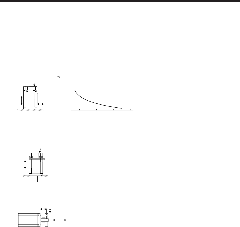
8. HG-JR SERIES
8 - 14
Note 1. When the power supply voltage drops, the output and the rated speed cannot be guaranteed.
2. If the load to motor inertia ratio exceeds the indicated value, contact your local sales office.
3. Except for the shaft-through portion. IP classifies the degrees of protection provided against the intrusion of solid objects and
water in electrical enclosures.
4. In the environment where the servo motor is exposed to oil mist, oil, or water, the servo motor of the standard specifications
may not be usable. Please contact your local sales office.
5. The following figure shows the vibration directions. The value is the one at the part that indicates the maximum value (normally
the opposite to load-side bracket). When the servo motor stops, fretting is likely to occur at the bearing. Therefore, suppress
the vibration to about half of the permissible value.
Y
X
Servo motor
Vibration
(both amplitudes) [ m]
Speed [r/min]
0 1000 2000 3000 4000 5000 6000 7000
10
100
1000
Vibration amplitude
6. V10 indicates that the amplitude of a single servo motor is 10 μm or less. The following figure shows the servo motor mounting
position for measurement and the measuring position.
Servo motor
Top
Bottom
Measuring position
7. The following shows permissible load for the shaft. Do not subject the shaft to load greater than the value in the specifications
list. The value assumes that the load is applied independently.
L
Radial load
Thrust load
L: Distance from flange mounting surface to load center
8. Values in parentheses are at the maximum torque of 400%. The maximum torque can be increased to 400% by changing the
servo amplifier. Refer to section 8.2 for the combinations.
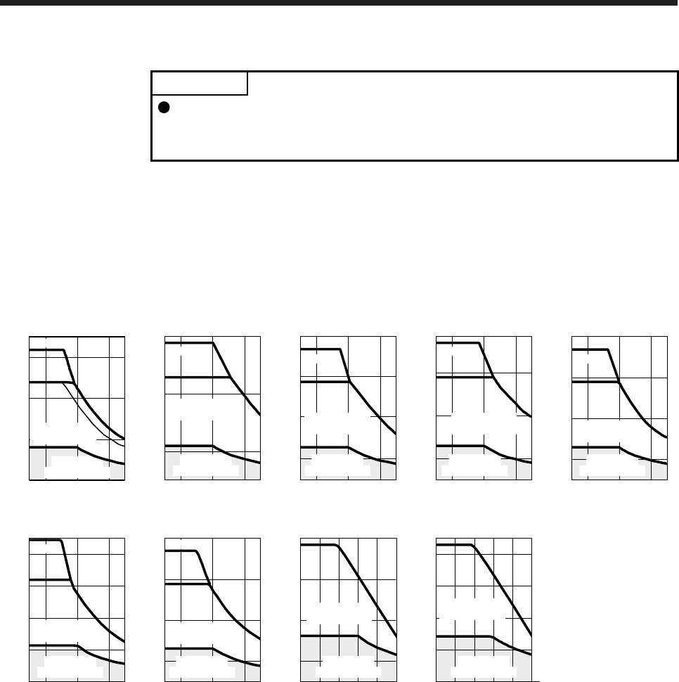
8. HG-JR SERIES
8 - 15
8.3.2 Torque characteristics
POINT
For the system where the unbalanced torque occurs, such as a vertical axis
system, the unbalanced torque of the machine should be kept at 70% or less of
the rated torque.
(1) 3-phase 200 V AC
When the power supply input of the servo amplifier is 3-phase 200 V AC or 1-phase 230 V AC, the
torque characteristic is indicated by the heavy line. For the 1-phase 200 V AC power supply, part of the
torque characteristic is indicated by the thin line. HG-JR53 and HG-JR73 support 1-phase power supply
input.
(a) 3000 r/min series
[HG-JR53]
1000 3000 5000 60000
(Note 4)
Speed [r/min]
Continuous
running range
Short-duration
running range
Torque [N•m]
0
7
4
2
6
[HG-JR73]
1000 3000 5000 60000
(Note 4)
Speed [r/min]
Continuous
running range
Short-duration
running range
Torque [N•m]
0
6
10
2
[HG-JR103]
1000 3000 5000 60000
(Note 4)
Speed [r/min]
Continuous
running range
Short-duration
running range
Torque [N•m]
10
2
6
14
0
[HG-JR153]
1000 3000 5000 60000
(Note 4)
Speed [r/min]
Continuous
running range
Short-duration
running range
Torque [N•m]
9
20
3
15
0
Speed [r/min]
Continuous
running range
Short-duration
running range
Torque [N•m]
[HG-JR203]
(Note 4)
1000 3000 5000 60000
12
28
4
20
0
[HG-JR353]
1000 3000 5000 60000
(Note 4)
Speed [r/min]
Continuous
running range
Short-duration
running range
Torque [N•m]
0
45
30
20
10
40
[HG-JR503]
1000 3000 5000 60000
(Note 4)
Speed [r/min]
Continuous
running range
Short-duration
running range
Torque [N•m]
0
30
10
50
70
[HG-JR703]
1000 2000 3000 4000 50000
0
70
30
10
50
Speed [r/min]
Continuous
running range
Short-duration
running range
Torque [N•m]
[HG-JR903]
1000 2000 3000 4000 50000 Speed [r/min]
Continuous
running range
Short-duration
running range
Torque [N•m]
0
90
40
20
60
80
Note. Value at the maximum torque 400%. The maximum torque can be increased to 400% by changing the servo amplifier. Refer to
section 8.2 for the combinations.
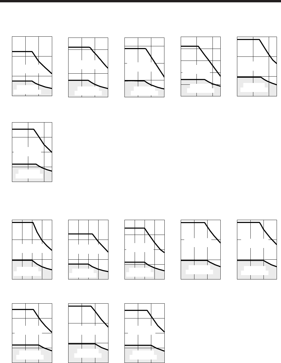
8. HG-JR SERIES
8 - 16
(b) 1500 r/min series
[HG-JR701M]
0
Torque [N•m]
0
180
60
120
1000 2000 3000
Speed [r/min]
Short-duration
running range
Continuous
running range
[HG-JR11K1M]
1000 2000 30000 Speed [r/min]
Continuous
running range
Short-duration
running range
Torque [N•m]
0
250
100
200
1000 2000 30000
[HG-JR15K1M]
Speed [r/min]
Continuous
running range
Short-duration
running range
Torque [N•m]
200
350
100
300
0
[HG-JR22K1M]
0 1000 2000 2500
Speed [r/min]
0
Torque [N•m]
500
100
200
300
400
Continuous
running range
Short-duration
running range
[HG-JR30K1M]
1000 2000 25000
Speed [r/min]
Torque [N•m]
600
200
400
0
Short-duration
running range
Continuous
running range
[HG-JR37K1M]
1000 2000 25000
Speed [r/min]
Torque [N•m]
0
800
400
200
600
Continuous
running range
Short-duration
running range
(c) 1000 r/min series
[HG-JR601]
500 1000 1500 20000 Speed [r/min]
Torque [N•m]
0
180
60
120
Short-duration
running range
Continuous
running range
[HG-JR801]
500 1000 1500 20000 Speed [r/min]
Torque [N•m]
0
300
100
200
Short-duration
running range
Continuous
running range
[HG-JR12K1]
500 1000 1500 20000 Speed [r/min]
Torque [N•m]
0
400
200
100
300
Continuous
running range
Short-duration
running range
[HG-JR15K1]
500 1000 15000 Speed [r/min]
Torque [N•m]
0
450
150
300 Short-duration
running range
Continuous
running range
[HG-JR20K1]
500 1000 15000 Speed [r/min]
Torque [N•m]
0
600
200
400
Continuous
running range
Short-duration
running range
[HG-JR25K1]
500 1000 15000 Speed [r/min]
Torque [N•m]
600
0
800
400
200
Short-duration
running range
Continuous
running range
[HG-JR30K1]
500 1000 15000 Speed [r/min]
Torque [N•m]
0
900
300
600
Short-duration
running range
Continuous
running range
[HG-JR37K1]
500 1000 15000 Speed [r/min]
Torque [N•m]
0
1200
600
300
900
Short-duration
running range
Continuous
running range
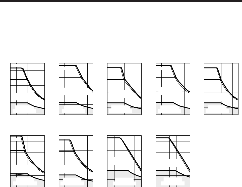
8. HG-JR SERIES
8 - 17
(2) 3-phase 400 V AC
When the power supply input of the servo amplifier is 3-phase 400 V AC, the torque characteristic is
indicated by the heavy line. For the 3-phase 380 V AC power supply, part of the torque characteristic is
indicated by the thin line.
(a) 3000 r/min series
[HG-JR534]
1000 3000 5000 60000
(Note 4)
Speed [r/min]
Continuous
running range
Short-duration
running range
Torque [N•m]
0
4
7
2
6
[HG-JR734]
1000 3000 5000 60000
(Note 4)
Speed [r/min]
Continuous
running range
Short-duration
running range
Torque [N•m]
0
6
10
2
[HG-JR1034]
1000 3000 5000 60000
(Note 4)
Speed [r/min]
Continuous
running range
Short-duration
running range
Torque [N•m]
0
10
2
6
14
[HG-JR1534]
1000 3000 5000 60000
(Note 4)
Speed [r/min]
Continuous
running range
Short-duration
running range
Torque [N•m]
0
9
20
3
15
[HG-JR2034]
1000 3000 5000 60000
(Note 4)
Speed [r/min]
Continuous
running range
Short-duration
running range
Torque [N•m]
0
12
28
4
20
[HG-JR3534]
1000 3000 5000 60000
(Note 4)
Speed [r/min]
Continuous
running range
Short-duration
running range
Torque [N•m]
45
30
20
10
40
0
(Note 4)
[HG-JR5034]
1000 3000 5000 60000 Speed [r/min]
Continuous
running range
Short-duration
running range
Torque [N•m]
0
70
30
10
50
[HG-JR7034]
1000 2000 3000 4000 50000 Speed [r/min]
Continuous
running range
Short-duration
running range
Torque [N•m]
0
70
30
10
50
[HG-JR9034]
1000 2000 3000 4000 50000
0
90
20
60
40
80
[H
Speed [r/min]
Continuous
running range
Short-duration
running range
Torque [N•m]
Note. Value at the maximum torque 400%. The maximum torque can be increased to 400% by changing the servo amplifier. Refer to
section 8.2 for the combinations.
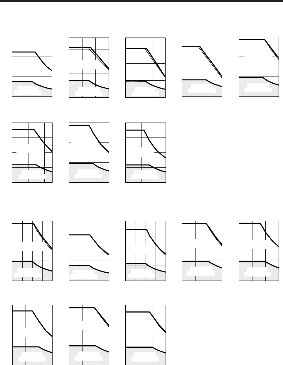
8. HG-JR SERIES
8 - 18
(b) 1500 r/min series
[HG-JR701M4]
0 1000 2000 3000
Speed [r/min]
Torque [N•m]
60
120
180
0
Short-duration
running range
Continuous
running range
[HG-JR11K1M4]
1000 2000 30000 Speed [r/min]
Continuous
running range
Short-duration
running range
Torque [N•m]
0
200
250
100
1000 2000 30000
[HG-JR15K1M4]
Speed [r/min]
Continuous
running range
Short-duration
running range
Torque [N•m]
0
200
350
100
300
[HG-JR22K1M4]
0 1000 2000 2500
Speed [r/min]
0
Torque [N•m]
500
100
200
300
400
Continuous
running range
Short-duration
running range
1000 2000 25000
Speed [r/min]
Torque [N•m]
0
600
200
400
[HG-JR30K1M4]
Short-duration
running range
Continuous
running range
[HG-JR37K1M4]
1000 2000 25000
Speed [r/min]
Torque [N•m]
0
800
400
200
600
Short-duration
running range
Continuous
running range
[HG-JR45K1M4]
1000 2000 25000
Speed [r/min]
Torque [N•m]
0
900
300
600 Short-duration
running range
Continuous
running range
[HG-JR55K1M4]
1000 2000 25000
Speed [r/min]
Torque [N•m]
Short-duration
running range
0
1200
600
300
900
Continuous
running range
(c) 1000 r/min series
[HG-JR6014]
500 1000 1500 20000 Speed [r/min]
Torque [N•m]
0
180
60
120 Short-duration
running range
Continuous
running range
[HG-JR8014]
500 1000 1500 20000 Speed [r/min]
Torque [N•m]
0
300
100
200
Short-duration
running range
Continuous
running range
[HG-JR12K14]
500 1000 1500 20000 Speed [r/min]
Torque [N•m]
0
400
200
100
300
Short-duration
running range
Continuous
running range
[HG-JR15K14]
500 1000 15000 Speed [r/min]
Torque [N•m]
0
450
150
300 Short-duration
running range
Continuous
running range
[HG-JR20K14]
500 1000 15000 Speed [r/min]
Torque [N•m]
0
600
200
400 Short-duration
running range
Continuous
running range
[HG-JR25K14]
500 1000 15000 Speed [r/min]
Torque [N•m]
0
800
400
200
600
Short-duration
running range
Continuous
running range
[HG-JR30K14]
500 1000 15000 Speed [r/min]
Torque [N•m]
0
900
300
600 Short-duration
running range
Continuous
running range
[HG-JR37K14]
500 1000 15000 Speed [r/min]
Torque [N•m]
0
1200
600
300
900
Short-duration
running range
Continuous
running range
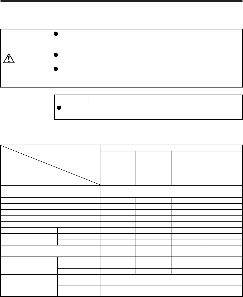
8. HG-JR SERIES
8 - 19
8.4 Electromagnetic brake characteristics
CAUTION
The electromagnetic brake is provided to prevent a drop at a power failure or
servo alarm occurrence during vertical drive or to hold a shaft at a stop. Do not
use it for normal braking (including braking at servo-lock).
Before operating the servo motor, be sure to confirm that the electromagnetic
brake operates properly.
The operation time of the electromagnetic brake differs depending on the power
supply circuit you use. Be sure to check the operation delay time with a real
machine.
POINT
The 1500 r/min series servo motor of 22 kW or more and 1000 r/min series
servo motor of 15 kW or more with an electromagnetic brake are not available.
The characteristics of the electromagnetic brake provided for the servo motor with an electromagnetic brake
are indicated below.
Servo motor
Item
HG-JR series
53(4)B
73(4)B
103(4)B
153(4)B
203(4)B
353(4)B
503(4)B
703(4)B
903(4)B
601(4)B
801(4)B
12K1(4)B
701M(4)B
11K1M(4)B
15K1M(4)B
Type (Note 1) Spring actuated type safety brake
Rated voltage (Note 4) 24 V DC 0
-10%
Power consumption [W] at 20 °C 11.7 23 34 32
Coil resistance (Note 6) [Ω] 49 25 16.8 18.2
Inductance (Note 6) [H] 0.37 0.25 1.10 0.73
Brake static friction torque [N•m] 6.6 16 44 126
Release delay time (Note 2) [s] 0.09 0.12 0.1 0.5
Braking delay time (Note 2) [s] DC off 0.03 0.03 0.03 0.2
Permissible braking work Per braking [J] 64 400 4500 5000
Per hour [J] 640 4000 45000 45200
Brake looseness at servo motor shaft (Note 5)
[degrees] 0.01 to 0.8 0.01 to 0.6 0.2 to 0.6 0.01 to 0.6
Brake life (Note 3)
Number of brakings
[times] 5000 5000 20000 20000
Work per braking [J] 64 400 1000 400
Selection example of surge
absorbers to be used (Note 7)
For the suppressed
voltage 125 V (Note 8) TND20V-680KB
For the suppressed
voltage 350 V (Note 8) TND10V-221KB
Note 1. There is no manual release mechanism. When it is necessary to hand-turn the servo motor shaft for machine centering, etc.,
use a separate 24 V DC power supply to release the brake electrically.
2. The value for initial on gap at 20 °C.
3. The brake gap will increase as the brake lining wears, but the gap is not adjustable.
The brake life indicated is the number of braking cycles after which adjustment will be required.
4.
A
lways prepare a power supply exclusively used for the electromagnetic brake.
5. These are design values. These are not guaranteed values.
6. These are measured values. These are not guaranteed values.
7. Select the electromagnetic brake control relay properly, considering the characteristics of the electromagnetic brake and surge
absorber. When you use a diode for a surge absorber, the electromagnetic braking time will be longer.
8. Manufactured by Nippon Chemi-Con Corporation.
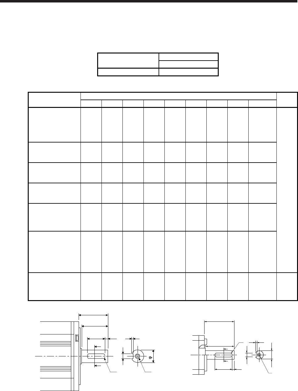
8. HG-JR SERIES
8 - 20
8.5 Servo motors with special shafts
The servo motors with special shafts indicated by the symbol (K) in the table are available. K is the symbol
attached to the servo motor model names.
Servo motor Shaft shape
Key shaft (without key)
HG-JR_(4)(B)K K
Variable dimension table [Unit: mm]
Servo motor Variable dimensions Figure
S R Q W QK QL U r Y
HG-JR53(4)(B)K
HG-JR73(4)(B)K
HG-JR103(4)(B)K
HG-JR153(4)(B)K
HG-JR203(4)(B)K
16h6 40 30
50
-0.030 25 2
3+0.1
0 2.5
M4
screw hole
depth 15
A
HG-JR353(4)(B)K
HG-JR503(4)(B)K 28h6 55 50
80
-0.036 36 5
4
+0.
2
0 4
M8
screw hole
depth 20
HG-JR703(4)(B)K
HG-JR903(4)(B)K 35+0.010
0 79 75
10 0
-0.036 55 5
5+0.
2
0 5
M8
screw hole
depth 20
HG-JR601(4)(B)K
HG-JR701M(4)(B)K 42h6 85 79
12 0
-0.040 70 5
5+0.
2
0 6
M8
screw hole
depth 19.8
HG-JR801(4)(B)K
HG-JR12K1(4)(B)K
HG-JR11K1M(4)(B)K
HG-JR15K1M(4)(B)K
55m6 116 110
16 0
-0.040 90 5
6+0.
2
0 8
M10
screw hole
depth 27
HG-JR15K1(4)K
HG-JR20K1(4)K
HG-JR25K1(4)K
HG-JR22K1M(4)K
HG-JR30K1M(4)K
HG-JR37K1M(4)K
65m6 140 130
18 0
-0.040 120 5
7+0.
2
0 9
M12
screw hole
depth 25
HG-JR30K1(4)K
HG-JR37K1(4)K
HG-JR45K1M4K
HG-JR55K1M4K
80m6 140 140
22 0
-0.040 132 7
9+0.
2
0 11
M16
screw hole
depth 30
B
S
QL
A
A
QK
Q
R
W
U
r Y
Shaft section view A-A
Q
R
QK
A
A
r
QL
W
Shaft section
view A-A
φS
U
Y
Figure A Figure B
Key shaft (without key)
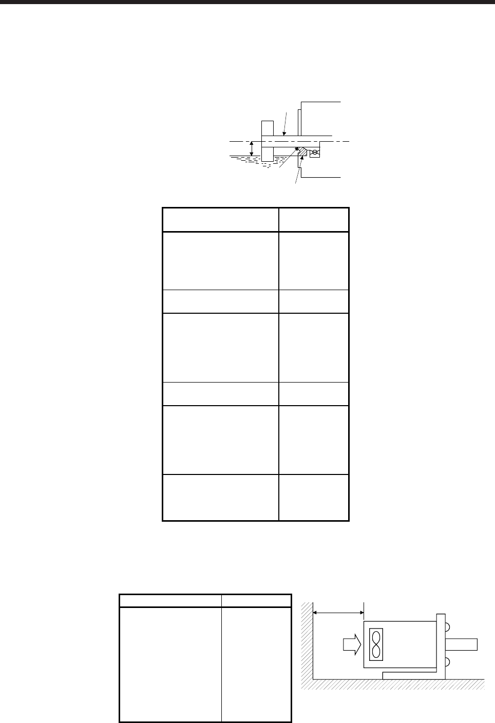
8. HG-JR SERIES
8 - 21
8.6 Oil seal
The oil seal prevents the entry of oil into the servo motor.
Install the servo motor horizontally, and set the oil level in the gear box to be lower than the oil seal lip
always.
GearShaft
Servo motor
Oil seal
Height above oil level h
Lip
Servo motor Oil level h
[mm]
HG-JR53(4)(B)
HG-JR73(4)(B)
HG-JR103(4)(B)
HG-JR153(4)(B)
HG-JR203(4)(B)
18
HG-JR353(4)(B)
HG-JR503(4)(B) 20
HG-JR703(4)(B)
HG-JR903(4)(B)
HG-JR601(4)(B)
HG-JR801(4)(B)
HG-JR12K1(4)(B)
HG-JR701M(4)(B)
25
HG-JR11K1M(4)(B)
HG-JR15K1M(4)(B) 40
HG-JR15K1(4)
HG-JR20K1(4)
HG-JR25K1(4)
HG-JR22K1M(4)
HG-JR30K1M(4)
HG-JR37K1M(4)
50
HG-JR30K1(4)
HG-JR37K1(4)
HG-JR45K1M4
HG-JR55K1M4
55
8.7 Cooling fan
For the servo motor with a cooling fan, leave the following distance between the servo motor's suction face
and the wall.
Servo motor Distance L [mm]
Servo motor
Cooling fan
L or more
Intake
HG-JR15K1(4)
HG-JR20K1(4)
HG-JR25K1(4)
HG-JR30K1(4)
HG-JR37K1(4)
HG-JR22K1M(4)
HG-JR30K1M(4)
HG-JR37K1M(4)
HG-JR45K1M4
HG-JR55K1M4
150
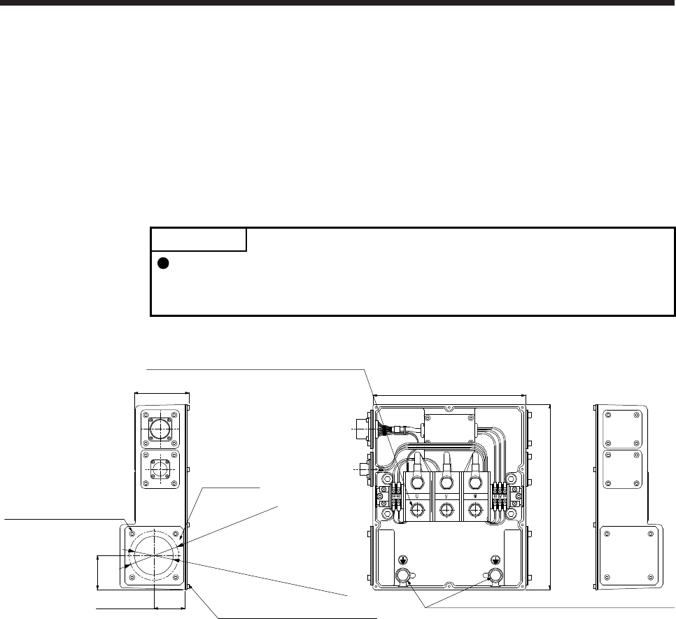
8. HG-JR SERIES
8 - 22
8.8 Dimensions
Moment of inertia on the table is the value calculated by converting the total value of moment of inertia for
servo motor and electromagnetic brake with servo motor shaft.
The dimensions without tolerances are general tolerance.
8.8.1 Terminal box detail diagram
HG-JR22K1M(4) to HG-JR37K1M(4)/HG-JR45K1M4/HG-JR55K1M4/HG-JR15K1(4) to HG-JR37K1(4)
POINT
The terminal box of the HG-JR22K1M(4) servo motor has been changed since
September 2014. Refer to appendix 9 for the terminal box detail diagram before
change.
[Unit: mm]
Terminal box lid: M4 screw (10)
Approx. 50
Approx. 55
φ63 (Cable gland mounting hole)
Terminal box side
Keep plate
Keep plate: M5 screw (4)
Keep plate side
φ80 hole
Approx. 89
Power supply terminal block: M10 screw (3
)
Protective earth (PE) terminal: M10 screw (2)
Approx. 247
Approx. 300
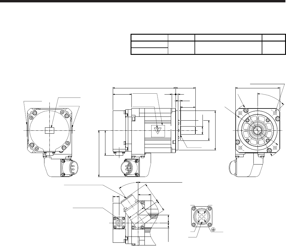
8. HG-JR SERIES
8 - 23
8.8.2 Standard (without an electromagnetic brake)
Model Output [kW] Moment of inertia J [× 10-4 kg•m2] Mass [kg]
HG-JR53 0.5 1.52 3.0
HG-JR534
[Unit: mm]
127.5 □90
φ118
φ100
φ80h7
φ16h6
40
7.5 5
30
38.2
50.9
Oil seal
Caution plate
Power supply connector
MS3102A18-10P
Encoder connector
CMV1-R10P
Caution plate
Motor plate
(Opposite side)
4-φ6.6 mounting hole
Use hexagon socket
head cap screw.
76 from the flange surface
93.8
13
45°
φ41
4.5
35°
1610.6
36
42.221.8
25.7
WV
U
Power connector viewed from
the connection side
Key
BC
AD
Caution plate
Top
Bottom
Top
Bottom
Top
Bottom
(PE)
BC42604* BC42615*
Motor plate
Top
Bottom
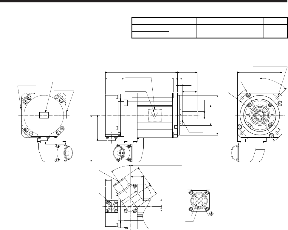
8. HG-JR SERIES
8 - 24
Model Output [kW] Moment of inertia J [× 10-4 kg•m2] Mass [kg]
HG-JR73 0.75 2.09 3.7
HG-JR734
[Unit: mm]
145.5 □90
φ118
φ100
φ80h7
40
7.5 5
30
38.2
50.9
Top
Bottom
Top
Bottom
Oil seal
Bottom
Top
Caution plate
Motor plate
Power supply connector
MS3102A18-10P
Encoder connector
CMV1-R10P
Caution plate
Motor plate
(Opposite side)
4-φ6.6 mounting hole
Use hexagon socket
head cap screw.
94 from the flange surface
93.8
13
45°
4.5
35°
1610.6
36
42.221.8
25.7
WV
U
Key
BC
AD
Caution plate
Power connector viewed from
the connection side
Top
Bottom
φ16h6
φ41
(PE)
BC42605* BC42616*
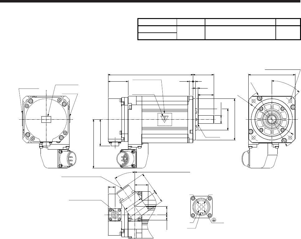
8. HG-JR SERIES
8 - 25
Model Output [kW] Moment of inertia J [× 10-4 kg•m2] Mass [kg]
HG-JR103 1.0 2.65 4.5
HG-JR1034
[Unit: mm]
163.5 □90
φ118
φ100
φ80h7
φ16h6
40
7.5 5
30
38.2
50.9
Top
Bottom
Oil seal
Caution plate
Motor plate
Power supply connector
MS3102A18-10P
Encoder connector
CMV1-R10P
Caution plate
Motor plate
(Opposite side)
4-φ6.6 mounting hole
Use hexagon socket
head cap screw.
112 from the flange surface
93.8
13
45°
φ41
4.5
35°
1610.6
36
42.221.8
25.7
WV
U
Key
BC
AD
Caution plate
Power connector viewed from
the connection side
Top
Bottom
Top
Bottom
Top
Bottom
(PE)
BC42606* BC42617*
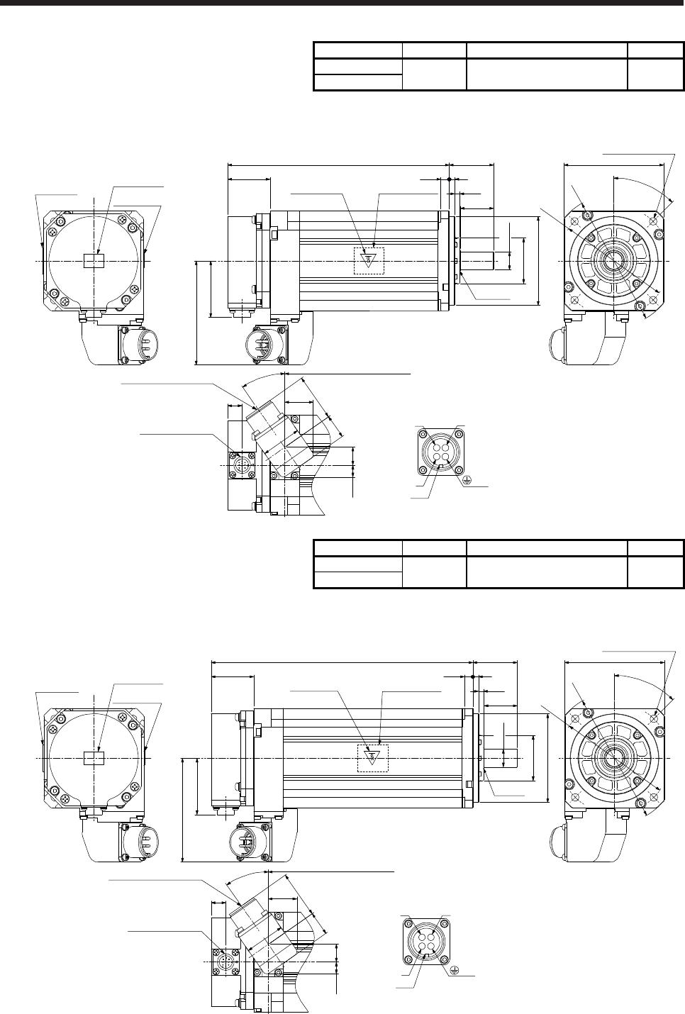
8. HG-JR SERIES
8 - 26
Model Output [kW] Moment of inertia J [× 10-4 kg•m2] Mass [kg]
HG-JR153 1.5 3.79 5.9
HG-JR1534
[Unit: mm]
199.5
φ80h7
φ16h6
40
7.5 5
30
38.2
50.9
Top
Bottom
Oil seal
Caution plate
Motor plate
Power supply connector
MS3102A18-10P
Encoder connector
CMV1-R10P
Caution plate Motor plate
(Opposite side)
148 from the flange surface
93.8
13
φ41
4.5
35°
1610.6
36
42.221.8
25.7
WV
U
Key
BC
AD
Caution plate
Power connector viewed from
the connection side
□90
φ118
φ100
4-φ6.6 mounting hole
Use hexagon socket
head cap screw.
45°
Top
Bottom
Top
Bottom
Top
Bottom
(PE)
BC42607* BC42618*
Model Output [kW] Moment of inertia J [× 10-4 kg•m2] Mass [kg]
HG-JR203 2.0 4.92 7.5
HG-JR2034
[Unit: mm]
235.5
φ80h7
φ16h6
40
7.5 5
30
38.2
50.9
Top
Bottom
Oil seal
Power supply connector
MS3102A18-10P
Encoder connector
CMV1-R10P
Caution plate Motor plate
(Opposite side)
184 from the flange surface
93.8
13
φ41
4.5
35°
1610.6
36
42.221.8
25.7
WV
U
Key
BC
AD
Caution plate
Motor plate
Caution plate
Power connector viewed from
the connection side
□90
φ118
φ100
4-φ6.6 mounting hole
Use hexagon socket
head cap screw.
45°
Top
Bottom
Top
Bottom
Top
Bottom
(PE)
BC42608* BC42619*
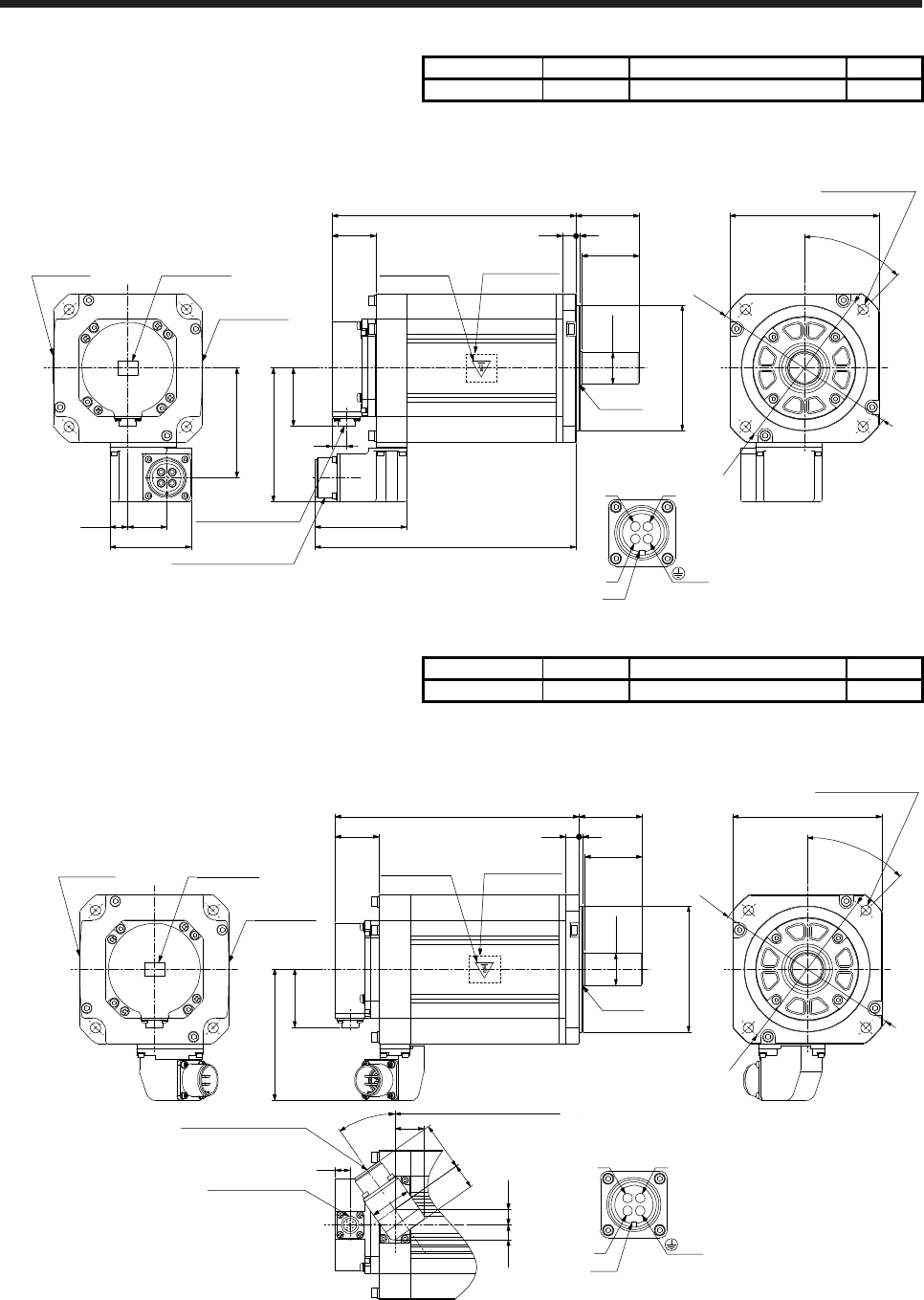
8. HG-JR SERIES
8 - 27
Model Output [kW] Moment of inertia J [× 10-4 kg•m2] Mass [kg]
HG-JR353 3.5 13.2 13
[Unit: mm]
55
312
50
φ110h7
Oil seal
213
38.2
50.9
116.8
φ28h6
□130
φ165
φ145
Power supply connector
MS3102A22-22P
Encoder connector
CMV1-R10P
Bottom
Top
Bottom
Top
Motor plate
(Opposite side)
Caution plate
Bottom
Top
4-φ9 mounting hole
Use hexagon socket
head cap screw.
80
228
15.5 34
71
95.8
13
45°
WV
U
Key
BC
AD
Caution plate
Caution plateMotor plate
Power connector viewed from
the connection side
Bottom
T
op
(PE)
BC42609*
Model Output [kW] Moment of inertia J [× 10-4 kg•m2] Mass [kg]
HG-JR3534 3.5 13.2 13
[Unit: mm]
55
312
50
φ110h7
Oil seal
213
38.2
50.9
114.8
13.5
161 from the flange surface
φ28h6
□130
45°
φ165
φ145
13.1
42.221.8
36
13
Power supply connector
MS3102A18-10P
Encoder connector
CMV1-R10P
Motor plate
(Opposite side)
Caution plate
Bottom
Top
35°
25.7
WV
U
Power connector viewed from
the connection side
Key
BC
AD
4-φ9 mounting hole
Use hexagon socket
head cap screw.
Bottom
Top
Bottom
Top
Caution plate
Caution plateMotor plate
Bottom
T
op
(PE)
BC42620*
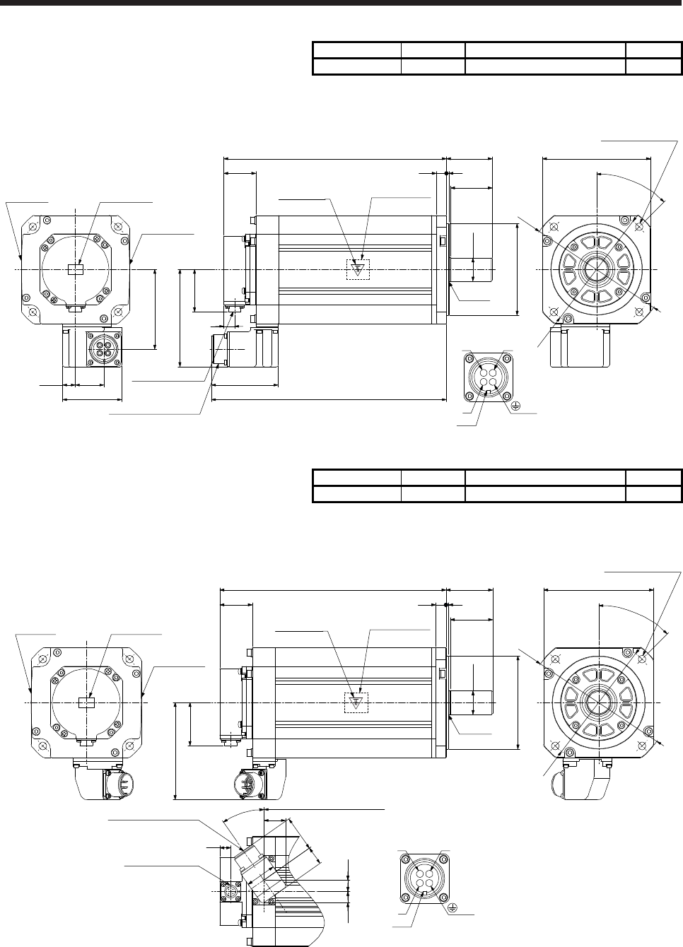
8. HG-JR SERIES
8 - 28
Model Output [kW] Moment of inertia J [× 10-4 kg•m2] Mass [kg]
HG-JR503 5.0 19.0 18
[Unit: mm]
Motor plate
(Opposite side)
Caution plate
55
312
50
φ110h7
Oil seal
267
38.2
50.9
φ28h6
□130
45°
φ165
φ145
116.8
Power supply connector
MS3102A22-22P
Encoder connector
CMV1-R10P 80
282
13
15.5 34
71
95.8
WV
U
Key
BC
AD
Power connector viewed from
the connection side
Bottom
Caution plate
Caution plateMotor plate
T
op
Bottom
Top
Bottom
Top
Bottom
Top
4-φ9 mounting hole
Use hexagon socket
head cap screw.
(PE)
BC42610*
Model Output [kW] Moment of inertia J [× 10-4 kg•m2] Mass [kg]
HG-JR5034 5.0 19.0 18
[Unit: mm]
55
312
50
φ110h7
Oil seal
267
38.2
50.9
114.8
13.5
215 from the flange surface
φ28h6
□130
45°
φ165
φ145
13.1
42.221.8
36
13
35°
25.7
WV
U
Key
BC
AD
Power connector viewed from
the connection side
Power supply connector
MS3102A18-10P
Encoder connector
CMV1-R10P
Caution plate
Caution plateMotor plate Motor plate
(Opposite side)
Caution plate
Bottom
Top
4-φ9 mounting hole
Use hexagon socket
head cap screw.
Bottom
Top
Bottom
Top
Bottom
T
op
(PE)
BC42621*
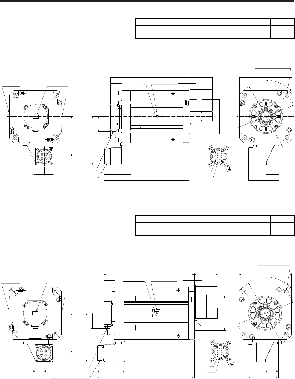
8. HG-JR SERIES
8 - 29
Model Output [kW] Moment of inertia J [× 10-4 kg•m2] Mass [kg]
HG-JR703 7.0 43.3 29
HG-JR7034
[Unit: mm]
φ114.3 0
-0.025
263.5
38.5
50.9
163.3
φ35+0.010
0
Oil seal
Power supply connector
MS3102A32-17P
Encoder connector
CMV1-R10P
Bottom
T
op
Motor plate
Caution plate
13
285.4
92.1
28.5
133.5
Bottom
Top
Bottom
Top
φ200
φ230
Caution plate
□176
45°
79
318
75
Motor plate
(Opposite side)
Caution plate
Bottom
Top
44
102.3
W
V
U
Power connector viewed from
the connection side
Key
BC
AD
4-φ13.5 mounting hole
Use hexagon socket
head cap screw.
(PE)
(Note) *3
(Note) *4
(Note) *2
(Note) *1
(Note) *3
(Note) *4
BC42611* BC42622*
(Note) *1
(Note) *2
Note. *1, *2, *3, and *4 are screw hole for eyebolt (M8).
Model Output [kW] Moment of inertia J [× 10-4 kg•m2] Mass [kg]
HG-JR903 9.0 55.8 36
HG-JR9034
[Unit: mm]
φ114.3 0
-0.025
303.5
φ35+0.010
0
Oil seal
Bottom
Top
φ200
φ230
325.4
92.1
28.5
133.5
Bottom
Top
Bottom
Top
38.5
50.9
163.3
Power supply connector
MS3102A32-17P
Encoder connector
CMV1-R10P
13
Motor plate
(Opposite side)
Caution plate
79
318
75
□176
45°
Bottom
Top
44
102.3
4-φ13.5 mounting hole
Use hexagon socket
head cap screw.
WV
U
Key
BC
AD
Motor plate
Caution plate
Caution plate
Power connector viewed from
the connection side
(PE)
(Note) *3
(Note) *4
(Note) *2
(Note) *1
(Note) *3
(Note) *4
BC42612* BC42623*
(Note) *2
(Note) *1
Note. *1, *2, *3, and *4 are screw hole for eyebolt (M8).
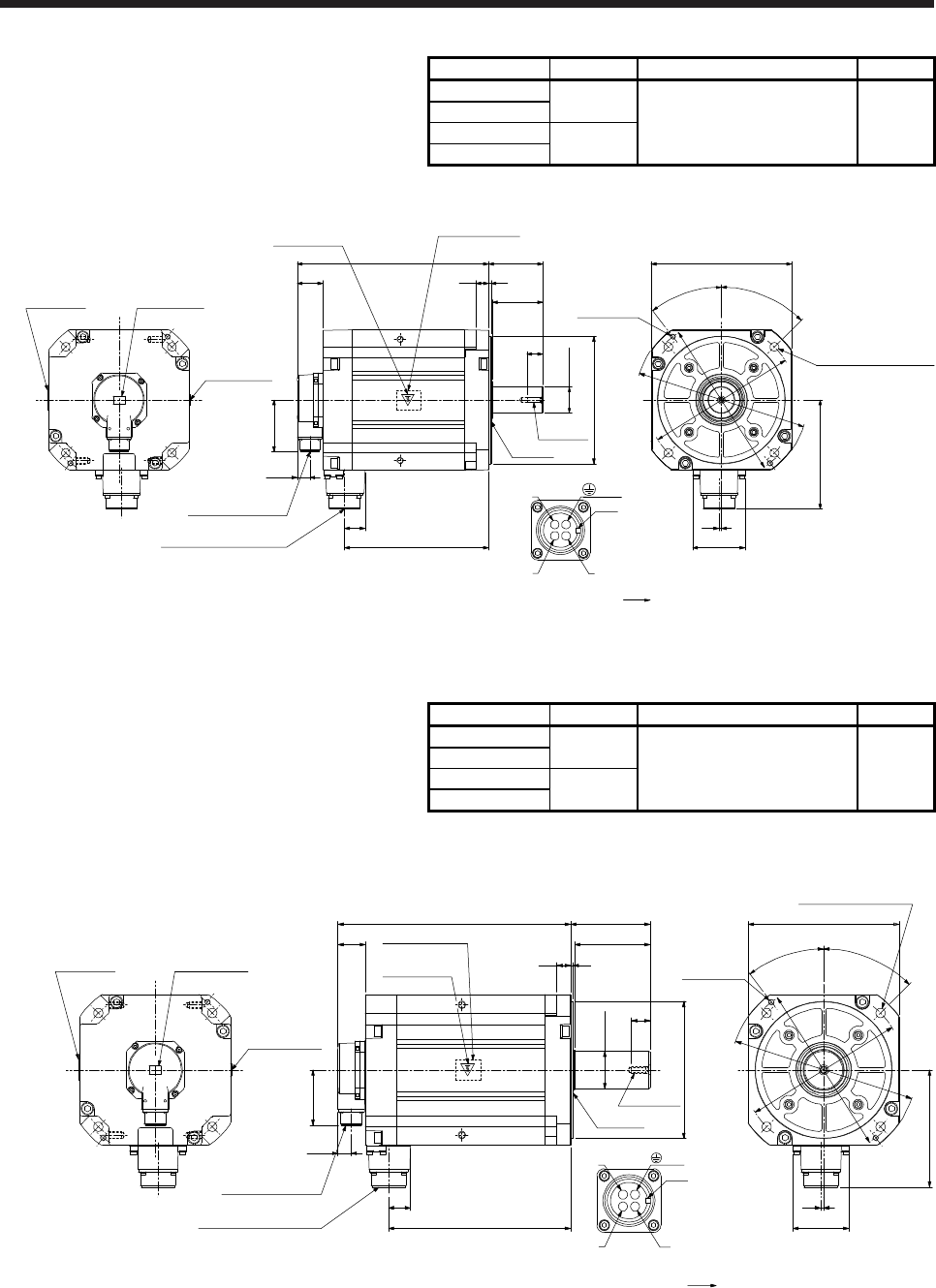
8. HG-JR SERIES
8 - 30
Model Output [kW] Moment of inertia J [× 10-4 kg•m2] Mass [kg]
HG-JR601 6
HG-JR6014 176 53
HG-JR701M 7
HG-JR701M4
[Unit: mm]
Power supply connector
Motor flange direction
BC43502* BC43503* BC43504* BC43505*
Caution plate
Caution plateMotor plate
Bottom
Top
Top
Bottom
Top
(Note)
*2
(Note)
*1
(Note)
*4 (Note)
*3
U
(PE)
W
V
B
C
A
D
Key
Bottom
Top
φ200h7
32
225.5
19.5
81
25
φ42h6
79
420
85299.5
Power supply connector
MS3102A32-17P
Encoder connector
MS3102A20-29P
40
(Note) *1,*2
(Note) *3,*4
Motor plate
Caution plate (Opposite side)
4
82
171.1
φ235
45°
37.5°
□220
φ250
φ270
2-M8 screw
4-φ13.5 mounting hole
Use hexagon socket
head cap screw.
Oil seal
M8 screw
Bottom
Note. *1, *2, *3, and *4 are screw hole for eyebolt (M10).
Model Output [kW] Moment of inertia J [× 10-4 kg•m2] Mass [kg]
HG-JR801 8
220 62
HG-JR8014
HG-JR11K1M 11
HG-JR11K1M4
[Unit: mm]
4
82
171.1
φ235
φ270
45°
37.5°
□220
4-φ13.5 mounting hole
Use hexagon socket
head cap screw.
2-M8 screw
φ250
φ200h7
32
265.5
19.5
81
27
φ55m6
M10 screw
Oil seal
110
420
116339.5
Motor plate
(Opposite side)
Caution plate
Power supply connector
MS3102A32-17P
Encoder connector
MS3102A20-29P
40
Power supply connector
Motor flange direction
Caution plate
Caution plate
Motor plate
Bottom
Top
Top
Bottom
T
op
Bottom
Top
U
W
V
B
C
A
D
Key
(Note) *3,*4
(Note) *1,*2
(Note)
*3
(Note)
*2
(Note)
*1
(Note)
*4
(PE)
BC42613A BC42624A BC43498* BC43499*
Bottom
Note. *1, *2, *3, and *4 are screw hole for eyebolt (M10).
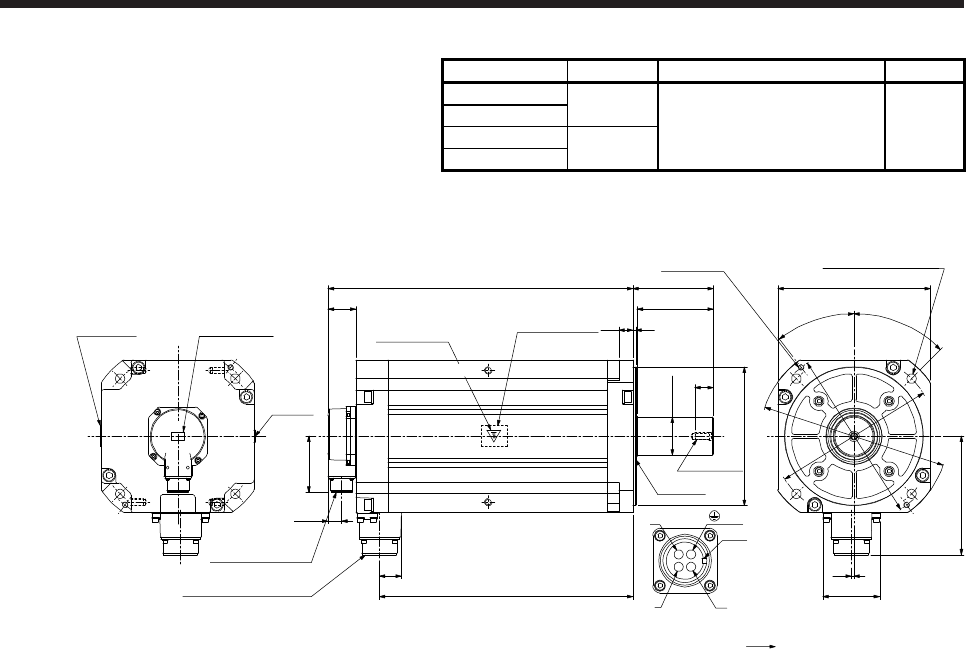
8. HG-JR SERIES
8 - 31
Model Output [kW] Moment of inertia J [× 10-4 kg•m2] Mass [kg]
HG-JR12K1 12
315 86
HG-JR12K14
HG-JR15K1M 15
HG-JR15K1M4
[Unit: mm]
365.5
32 4
82
171.1
φ235
φ270
45°
37.5°
□220
2-M8 screw
φ55m6
φ200h7
Oil seal
M10 screw
27
110
116
420
439.5
19.5
81
Motor plate
(Opposite side)
φ250
40
4-φ13.5 mounting hole
Use hexagon socket
head cap screw.
Power supply connector
Motor flange direction
Power supply connector
MS3102A32-17P
Encoder connector
MS3102A20-29P
U
W
V
B
C
A
D
Key
Caution
plate
Caution plateMotor plate Caution plate
Bottom
Top
Top
Bottom
Top
BC42614A BC42625A BC43500* BC43501*
(Note) *3,*4
(Note) *1,*2
(Note)
*3
(Note)
*2
(Note)
*1
(Note)
*4
(PE)
Bottom
Top
Bottom
Note. *1, *2, *3, and *4 are screw hole for eyebolt (M10).
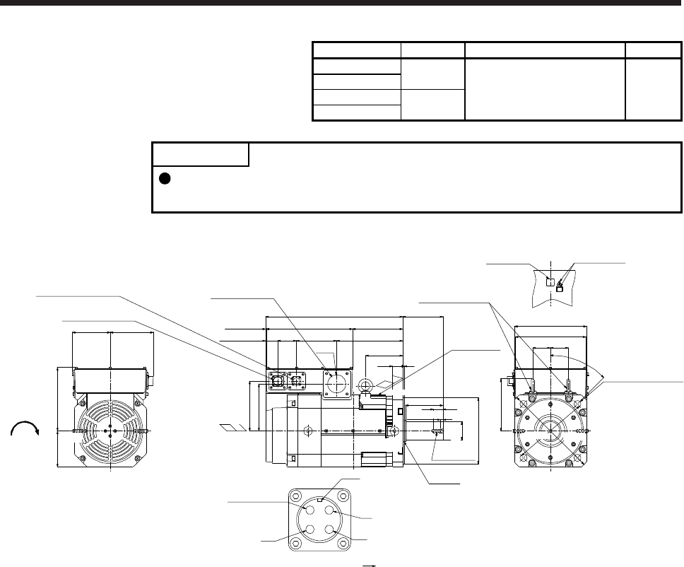
8. HG-JR SERIES
8 - 32
Model Output [kW] Moment of inertia J [× 10-4 kg•m2] Mass [kg]
HG-JR15K1 15
489 120
HG-JR15K14
HG-JR22K1M 22
HG-JR22K1M4
POINT
The appearance of the HG-JR22K1M(4) servo motor has been changed since
September 2014. Refer to appendix 9 for the dimensions before change.
[Unit: mm]
4-φ24 mounting hole
Use hexagon socket
head cap screw.
φ230h7
□250 (Flange)
140
Intake
Exhaust
476
174
220125
Eyebolt (Note 2, 3)
Power lead hole
Encoder connector
MS3102A20-29P
Cooling fan connector
CE05-2A14S-2P
Caution plate
Motor plate
Top
247
Oil seal
BC41678* BC41679* BC43641* BC43642*
Top
Bottom
Top
Motor plate/
Caution plate
Cooling fan
rotation
direction
φ63
229
163
45°
φ265
φ330
150133
174
62 62
300
129
M12 screw
33
535
14065
Approx. 42
(Note 1)
*1,*2
(Note 1)
*1
Approx. 2
BV
BW
Cooling fan connector
Motor flange direction
BU
To be left open
Key
181
130
φ65m6
(Note 1)
*3,*4
(Note 1)
*3 (Note 1)
*4
Approx. 8
Bottom
Bottom
(Note 1)
*2
Note 1. *1, *2, *3, and *4 are screw hole for eyebolt (M12).
2.
A
n angle adjusting washer is inserted into the eyebolt.
3. When the motor is used without the eyebolt, plug the threaded hole with a bolt of M12 × 20 or less.
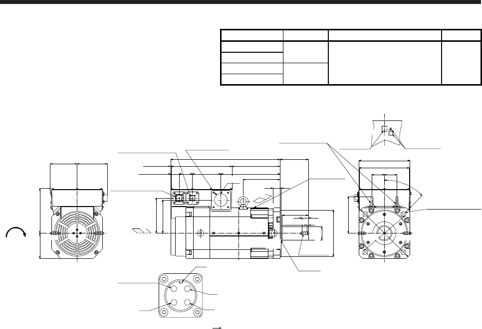
8. HG-JR SERIES
8 - 33
Model Output [kW] Moment of inertia J [× 10-4 kg•m2] Mass [kg]
HG-JR20K1 20
HG-JR20K14 627 145
HG-JR30K1M 30
HG-JR30K1M4
[Unit: mm]
φ230h7
140
Intake
Exhaust 5
538
236300
Approx. 42
35
M12 screw
Power lead hole
Encoder connector
MS3102A20-29P
Cooling fan connector
CE05-2A14S-2P
130
Oil seal
Top
Motor plate/
Caution plate
Cooling fan
rotation
direction
Caution plateMotor plate
Top
Top
291
33
163
174
□250 (Flange)
Eyebolt (Note 2, 3)
247
45°
φ265
φ330
62 62
220125
150133
14065 181
4-φ24 mounting hole
Use hexagon socket
head cap screw.
(Note 1)
*1,*2
(Note 1)
*1
Approx. 2
BV
BW
Cooling fan connector
Motor flange direction BC41680* BC41681* BC43643* BC43644*
BU
To be left open
Key
181
φ65m6
φ63
(Note 1)
*3,*4
Bottom
Approx. 8
(Note 1)
*2 (Note 1)
*3 (Note 1)
*4
Bottom
Bottom
Note 1. *1, *2, *3, and *4 are screw hole for eyebolt (M12).
2.
A
n angle adjusting washer is inserted into the eyebolt.
3. When the motor is used without the eyebolt, plug the threaded hole with a bolt of M12 × 20 or less.
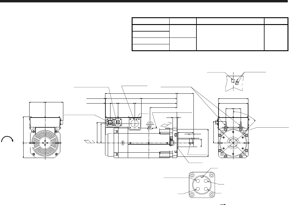
8. HG-JR SERIES
8 - 34
Model Output [kW] Moment of inertia J [× 10-4 kg•m2] Mass [kg]
HG-JR25K1 25
HG-JR25K14 764 165
HG-JR37K1M 37
HG-JR37K1M4
[Unit: mm]
Cooling fan
rotation
d
irection
Caution plate
Motor plate
Top
Intake
□250 (Flange)
Eyebolt (Note 2, 3)
247
45°
φ265
φ330
62 62
4-φ24 mounting hole
Use hexagon socket
head cap screw.
220125
150133
(Note 1)
*1
140
35 5
600
298300
224
35314065
Approx. 42
φ230h7
Exhaust
Oil seal
33
M12 screw
174
163
Power lead hole
Encoder connector
MS3102A20-29P
Cooling fan connector
CE05-2A14S-2P
φ63
Approx. 2
BV
BW
Cooling fan connector
Motor flange direction
BC41682* BC41683* BC43645* BC43646*
BU
To be left open
Key
181
130
(Note 1)
*1,*2
(Note 1)
*3,*4
φ65m6
(Note 1)
*3 (Note 1)
*4
Motor plate/Caution plate
Top Bottom
Approx. 8
Bottom Top
Bottom
(Note 1)
*2
Note 1. *1, *2, *3, and *4 are screw hole for eyebolt (M12).
2.
A
n angle adjusting washer is inserted into the eyebolt.
3. When the motor is used without the eyebolt, plug the threaded hole with a bolt of M12 × 20 or less.
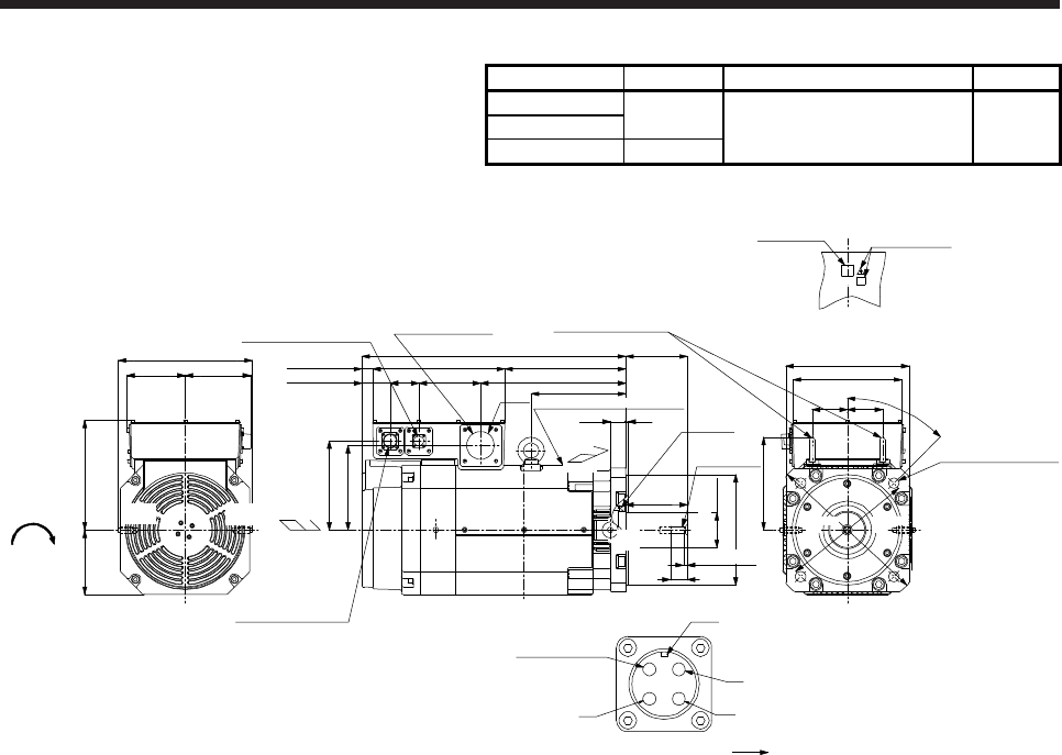
8. HG-JR SERIES
8 - 35
Model Output [kW] Moment of inertia J [× 10-4 kg•m2] Mass [kg]
HG-JR30K1 30
HG-JR30K14 1377 215
HG-JR45K1M4 45
[Unit: mm]
Caution plate
Motor plate
Top Top
Bottom
600
330
275300 140
35 5
140
φ250h7
φ63
Power lead hole
M16 screw
Oil seal
Top
Exhaust
□280 (Flange)
247
45°
φ300
φ370
4-φ24 mounting hole
Use hexagon socket
head cap screw.
Encoder connector
MS3102A20-29P
Cooling fan connector
CE05-2A14S-2P
Intake
Cooling fan
rotation
direction
39
80 80
202
Eyebolt (Note 2, 3)
Approx. 25
192
215
140
65
Approx. 65
305
133 150
250147
(Note 1)
*1,*2
BV
BW
Cooling fan connector
Motor flange direction BC41684* BC41685* BC43647*
BU
To be left open
Key
210
(Note 1)
*2 (Note 1)
*1
φ80m6
(Note 1)
*3,*4
Motor plate/Caution plate
Bottom
Approx. 9
(Note 1)
*3 (Note 1)
*4
Bottom
Note 1. *1, *2, *3, and *4 are screw hole for eyebolt (M16).
2.
A
n angle adjusting washer is inserted into the eyebolt.
3. When the motor is used without the eyebolt, plug the threaded hole with a bolt of M16 × 20 or less.
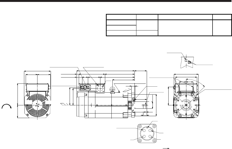
8. HG-JR SERIES
8 - 36
Model Output [kW] Moment of inertia J [× 10-4 kg•m2] Mass [kg]
HG-JR37K1 37
HG-JR37K14 1637 240
HG-JR55K1M4 55
[Unit: mm]
300
140
35 5
140
φ250h7
φ63
Power lead hole
M16 screw
Oil seal
Top
Exhaust
□280 (Flange)
247
45°
φ300
φ370
4-φ24 mounting hole
Use hexagon socket
head cap screw.
305
133 150
250147
Encoder connector
MS3102A20-29P
Cooling fan connector
CE05-2A14S-2P
Intake
Cooling fan
rotation
d
irection
Caution plate
Motor plate
Top Top
Bottom
664
339
394
Approx. 25
202
192
39
80 80
253 Eyebolt (Note 2, 3)
14065Approx. 65
210
BV
BW
Cooling fan connector
Motor flange direction BC41686* BC41687* BC43648*
BU
To be left open
Key
(Note 1)
*2 (Note 1)
*1 (Note 1)
*3,*4
φ80m6
(Note 1)
*4
(Note 1)
*3
Approx. 9
Bottom
Motor plate/Caution plate
Bottom
(Note 1)
*1,*2
Note 1. *1, *2, *3, and *4 are screw hole for eyebolt (M16).
2.
A
n angle adjusting washer is inserted into the eyebolt.
3. When the motor is used without the eyebolt, plug the threaded hole with a bolt of M16 × 20 or less.
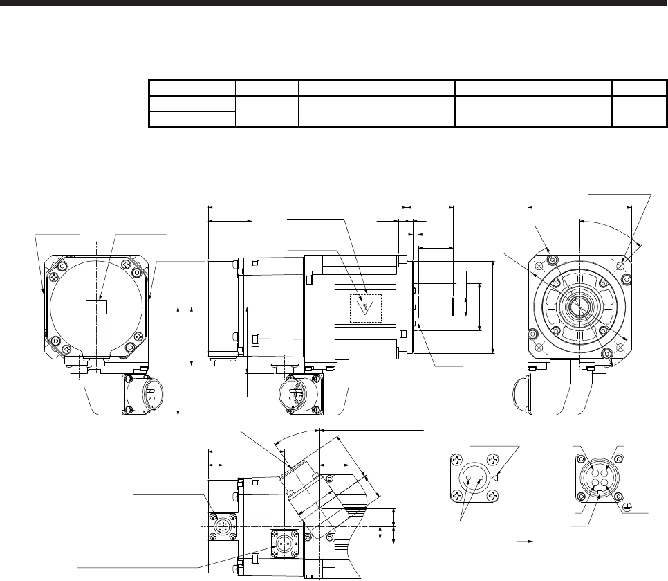
8. HG-JR SERIES
8 - 37
8.8.3 With an electromagnetic brake
Model Output [kW] Brake static friction torque [N•m] Moment of inertia J [× 10-4 kg•m2] Mass [kg]
HG-JR53B 0.5 6.6 2.02 4.4
HG-JR534B
[Unit: mm]
173
φ80h7
φ16h6
40
7.5 5
30
38
50.9
Top
Oil seal
Caution plateMotor plate
Caution plate
Motor plate
(Opposite side)
76 from the flange surface
93.8
13
φ41
4.5
35°
16
10.6
36
42.221.8
57.4
15
66.5
25.7
Caution plate
Top
Bottom
Bottom
Top
Bottom
Top
□90
φ118
φ100
4-φ6.6 mounting hole
Use hexagon socket
head cap screw.
45°
Electromagnetic brake connector
Motor flange direction
Electromagnetic
brake
WV
U
Power connector viewed from
the connection side
Key
BC
AD
Main key
position mark
Encoder connector
CMV1-R10P
Electromagnetic brake connector
CMV1-R2P
Power supply connector
MS3102A18-10P
(PE)
BC42626* BC42637*
Bottom
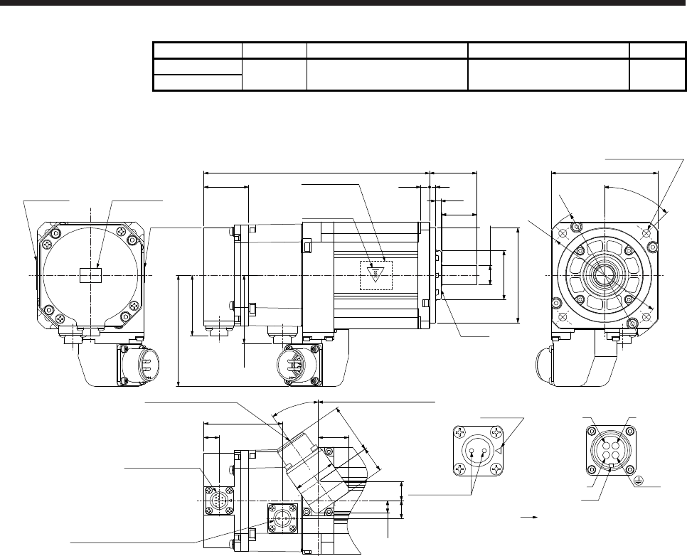
8. HG-JR SERIES
8 - 38
Model Output [kW] Brake static friction torque [N•m] Moment of inertia J [× 10-4 kg•m2] Mass [kg]
HG-JR73B 0.75 6.6 2.59 5.1
HG-JR734B
[Unit: mm]
191
φ80h7
φ16h6
40
7.5 5
30
38
50.9
Top
Bottom
Top
Bottom
Oil seal
Bottom
T
op
Bottom
Top
Caution plate
Motor plate
Caution plate
Motor plate
(Opposite side)
94 from the flange surface
93.8
13
φ41
4.5
35°
16
10.6
36
42.221.8
57.4
15
66.5
25.7
□90
φ118
φ100
4-φ6.6 mounting hole
Use hexagon socket
head cap screw.
45°
Caution plate
Electromagnetic brake connector
Motor flange direction
Electromagnetic
brake
W
V
U
Power connector viewed from
the connection side
Key
BC
AD
Main key
position mark
Encoder connector
CMV1-R10P
Electromagnetic brake connector
CMV1-R2P
Power supply connector
MS3102A18-10P
(PE)
BC42627* BC42638*
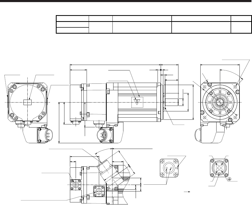
8. HG-JR SERIES
8 - 39
Model Output [kW] Brake static friction torque [N•m] Moment of inertia J [× 10-4 kg•m2] Mass [kg]
HG-JR103B 1.0 6.6 3.15 5.9
HG-JR1034B
[Unit: mm]
209 □90
φ118
φ100
φ80h7
φ16h6
40
7.5 5
30
38
50.9
Top
Bottom
Top
Bottom
Oil seal
Bottom
Top
Bottom
Top
Caution plateMotor plate
Caution plate
Motor plate
(Opposite side)
112 from the flange surface
93.8
13
45°
φ41
4.5
35°
16
10.6
36
42.221.8
57.4
15
66.5
4-φ6.6 mounting hole
Use hexagon socket
head cap screw.
25.7
Caution plate
Electromagnetic brake connector
Motor flange direction
Electromagnetic
brake
WV
U
Power connector viewed from
the connection side
Key
BC
AD
Main key
position mark
Encoder connector
CMV1-R10P
Electromagnetic brake connector
CMV1-R2P
Power supply connector
MS3102A18-10P
(PE)
BC42628* BC42639*
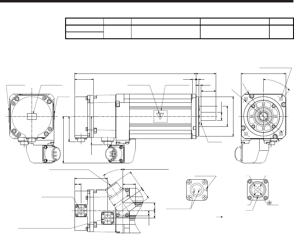
8. HG-JR SERIES
8 - 40
Model Output [kW] Brake static friction torque [N•m] Moment of inertia J [× 10-4 kg•m2] Mass [kg]
HG-JR153B 1.5 6.6 4.29 7.3
HG-JR1534B
[Unit: mm]
BC42629* BC42640*
245 □90
φ118
φ100
φ80h7
φ16h6
40
7.5 5
30
38
50.9
Top
Bottom
Top
Bottom
Oil seal
Bottom
Top
Bottom
Top
Caution plateMotor plate Caution plate Motor plate
(Opposite side)
4-φ6.6 mounting hole
Use hexagon socket
head cap screw.
148 from the flange surface
93.8
13
45°
φ41
4.5
35°
16
10.6
36
42.221.8
57.4
15
66.5
25.7
Caution
plate
Electromagnetic brake connector
Motor flange direction
Electromagnetic
brake
W
V
U
Power connector viewed from
the connection side
Key
BC
AD
Main key
position mark
Encoder connector
CMV1-R10P
Electromagnetic brake connector
CMV1-R2P
Power supply connector
MS3102A18-10P
(PE)
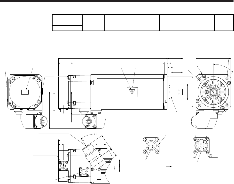
8. HG-JR SERIES
8 - 41
Model Output [kW] Brake static friction torque [N•m] Moment of inertia J [× 10-4 kg•m2] Mass [kg]
HG-JR203B 2.0 6.6 5.42 8.9
HG-JR2034B
[Unit: mm]
281 □90
φ118
φ100
φ80h7
φ16h6
40
7.5 5
30
38
50.9
Top
Bottom
Top
Bottom
Oil seal
Bottom
Top
Bottom
Top
Caution plateMotor plate Caution plate Motor plate
(Opposite side)
184 from the flange surface
93.8
13
45°
φ41
4.5
35°
16
10.6
36
42.221.8
57.4
15
66.5
4-φ6.6 mounting hole
Use hexagon socket
head cap screw.
25.7
Caution
plate
Electromagnetic brake connector
Motor flange direction
Electromagnetic
brake
WV
U
Power connector viewed from
the connection side
Key
BC
AD
Main key
position mark
Encoder connector
CMV1-R10P
Electromagnetic brake connector
CMV1-R2P
Power supply connector
MS3102A18-10P
(PE)
BC42630* BC42641*
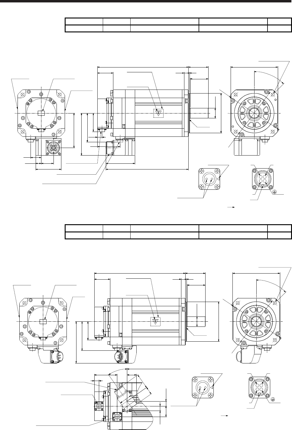
8. HG-JR SERIES
8 - 42
Model Output [kW] Brake static friction torque [N•m] Moment of inertia J [× 10-4 kg•m2] Mass [kg]
HG-JR353B 3.5 16 15.4 15
[Unit: mm]
Motor plate
(Opposite side)
Caution plate
Bottom
Top
55
312
50
φ110h7
251.5
43.5
50.9
79.9
116.8
φ28h6
Caution plate
Caution plate
Motor plate
Bottom
Top
Bottom
Top
Bottom
Top
□130
45°
4-φ9 mounting hole
Use hexagon socket
head cap screw.
φ165
φ145
80
228
13
63
15.5 34
71
95.8
29
Electromagnetic brake connector
Motor flange direction
Electromagnetic
brake
WV
U
Power connector viewed from
the connection side
Key
BC
AD
Main key
position mark
CMV1-R2P
Electromagnetic brake connector
MS3102A22-22P
Power supply connector
CMV1-R10P
Encoder connector
Oil seal
(PE)
BC42631*
Model Output [kW] Brake static friction torque [N•m] Moment of inertia J [× 10-4 kg•m2] Mass [kg]
HG-JR3534B 3.5 16 15.4 15
[Unit: mm]
Motor plate
(Opposite side)
Caution plate
Bottom
Top
55
312
50
φ110h7
Oil seal
251.5
43.5
50.9
79.9
114.8
13.529
63
161 from the flange surface
φ28h6
Caution
plate
Caution plateMotor plate
Bottom
Top
Bottom
Top
Bottom
Top
□130
45°
4-φ9 mounting hole
Use hexagon socket
head cap screw.
φ165
φ145
35°
36
42.221.8
13.1
25.7
13
Electromagnetic brake connector
Motor flange direction
Electromagnetic
brake
WV
U
Power connector viewed from
the connection side
Key
BC
AD
Main key
position mark
CMV1-R2P
Electromagnetic brake connector
MS3102A18-10P
Power supply connector
CMV1-R10P
Encoder connector
(PE)
BC42642*
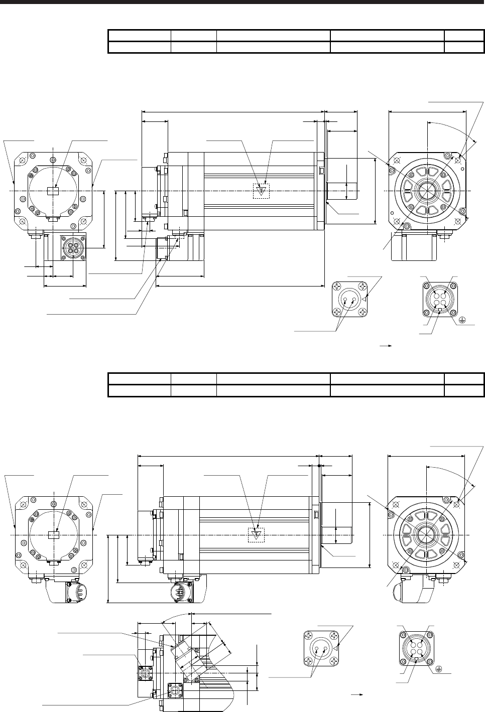
8. HG-JR SERIES
8 - 43
Model Output [kW] Brake static friction torque [N•m] Moment of inertia J [× 10-4 kg•m2] Mass [kg]
HG-JR503B 5.0 16 21.2 20
[Unit: mm]
Motor plate
(Opposite side)
Caution plate
Bottom
Top
55
312
50
305.5
43.5
Caution plate
Caution plate
Motor plate
Bottom
Top
Bottom
Top
Bottom
Top
□130
45°
4-φ9 mounting hole
Use hexagon socket
head cap screw.
φ165
φ28h6
φ145
50.9
79.9
116.8
80
282
13
63
15.5 34
71
95.8
29
Electromagnetic brake connector
Motor flange direction
Electromagnetic
brake
WV
U
Power connector viewed from
the connection side
Key
BC
AD
Main key
position mark
CMV1-R2P
Electromagnetic brake connector
MS3102A22-22P
Power supply connector
CMV1-R10P
Encoder connector
Oil seal
φ110h7
(PE)
BC42632*
Model Output [kW] Brake static friction torque [N•m] Moment of inertia J [× 10-4 kg•m2] Mass [kg]
HG-JR5034B 5.0 16 21.2 20
[Unit: mm]
21.8
55
312
50
φ110h7
305.5
43.5
50.9
79.9
114.8
13.529
13
63
215 from the flange surface
□130
45°
φ165
φ145
36
42.2
13.1
φ28h6
35°
25.7
Caution
plate
Caution plateMotor plate
Bottom
Top
Bottom
Top
Bottom
Top
Motor plate
(Opposite side)
Caution plate
Bottom
Top
Oil seal
4-φ9 mounting hole
Use hexagon socket
head cap screw.
Electromagnetic brake connector
Motor flange direction
Electromagnetic
brake
WV
U
Power connector viewed from
the connection side
Key
BC
AD
Main key
position mark
CMV1-R2P
Electromagnetic brake connector
MS3102A18-10P
Power supply connector
CMV1-R10P
Encoder connector
(PE)
BC42643*
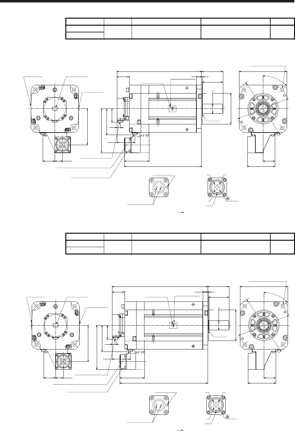
8. HG-JR SERIES
8 - 44
Model Output [kW] Brake static friction torque [N•m] Moment of inertia J [× 10-4 kg•m2] Mass [kg]
HG-JR703B 7.0 44 52.9 35
HG-JR7034B
[Unit: mm]
79
318
75
φ114.3 0
-0.025
313
45.5
50.9
96.9
163.3
Oil seal
Bottom
Top
Motor plate
Caution plate
13
66.5
285.4
92.128.5
133.5
44
Bottom
Top
Bottom
Top
Caution plate
□176
45°
φ200
Motor plate
(Opposite side)
Caution plate
Bottom
Top
44
102.3
4-φ13.5 mounting hole
Use hexagon socket
head cap screw.
Electromagnetic brake connector
Motor flange direction
Electromagnetic
brake
WV
U
Power connector viewed from
the connection side
Key
BC
AD
Main key
position mark
CMV1-R2P
MS3102A32-17P
CMV1-R10P
Electromagnetic brake connector
Power supply connector
Encoder connector
φ230
φ35+0.010
0
(PE)
BC42633* BC42644*
(Note) *3
(Note) *4
(Note) *2
(Note) *1
(Note) *3
(Note) *4
(Note) *2
(Note) *1
Note. *1, *2, *3, and *4 are screw hole for eyebolt (M8).
Model Output [kW] Brake static friction torque [N•m] Moment of inertia J [× 10-4 kg•m2] Mass [kg]
HG-JR903B 9.0 44 65.4 42
HG-JR9034B
[Unit: mm]
79
3
18
75
φ114.3 0
-0.025
353
45.5
50.9
96.9
163.3
□176
45°
Oil seal
Motor plate
(Opposite side)
Caution plate
Bottom
Top
4-φ13.5 mounting hole
Use hexagon socket
head cap screw.
Motor plate
Caution plate
φ200
13
66.5
325.4
92.1
28.5
133.5
44
Bottom
Top
Bottom
Top
Caution plate
Bottom
Top
44
102.3
Electromagnetic brake connector
Motor flange direction
Electromagnetic
brake
WV
U
Power connector viewed from
the connection side
Key
BC
AD
Main key
position mark
CMV1-R2P
MS3102A32-17P
CMV1-R10P
Electromagnetic brake connector
Power supply connector
Encoder connector
φ230
φ35 +0.010
0
(PE)
BC42634* BC42645*
(Note) *3
(Note) *4
(Note) *2
(Note) *1
(Note) *3
(Note) *4
(Note) *2
(Note) *1
Note. *1, *2, *3, and *4 are screw hole for eyebolt (M8).
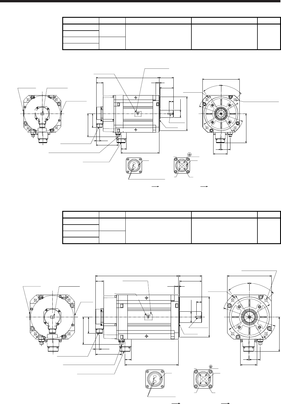
8. HG-JR SERIES
8 - 45
Model Output [kW] Brake static friction torque [N•m] Moment of inertia J [× 10-4 kg•m2] Mass [kg]
HG-JR601B 6
HG-JR6014B 126 196 65
HG-JR701MB 7
HG-JR701M4B
[Unit: mm]
U
(PE)
W
V
B
C
A
D
Power connector
Motor flange direction
BC43510* BC43511* BC43512* BC43513*
Key
B
A
Electromagnetic brake connector
Motor flange direction
Electromagnetic brake
Caution plate
Caution plate
Motor plate
Bottom
Top
Bottom
Top
(Note)
*2
(Note)
*1
(Note)
*4
(Note)
*3
Key
Top
Bottom
Top
φ200h7
225.5
25
φ42h6
79
420
85372
(Note) *1,*2
Motor plate
(Opposite side)
130
136.2
19.5
Power connector
MS3102A32-17P
Electromagnetic brake connector
MS3102A10SL-4P
Encoder connector
MS3102A20-29P
Caution plate
81
40
82
4 54
171.1
□220
45°
37.5°
2-M8 screw
φ270
φ250
φ235
4-φ13.5 mounting hole
Use hexagon socket
head cap screw.
Oil seal
M8 screw
32
(Note) *3,*4
Bottom
Note. *1, *2, *3, and *4 are screw hole for eyebolt (M10).
Model Output [kW] Brake static friction torque [N•m] Moment of inertia J [× 10-4 kg•m2] Mass [kg]
HG-JR801B 8
126 240 74
HG-JR8014B
HG-JR11K1MB 11
HG-JR11K1M4B
[Unit: mm]
φ200h7
27
φ55m6
110
116
4
20
412
40
32
265.5
130
136.2
81
19.5
Power supply connector
MS3102A32-17P
Electromagnetic brake connector
MS3102A10SL-4P
Encoder connector
MS3102A20-29P
82
4 54
171.1
□220
45°
37.5°
2-M8 screw
φ270
φ250
φ235
4-φ13.5 mounting hole
Use hexagon socket
head cap screw.
U
W
V
B
C
A
D
Power supply connector
Motor flange direction
Key
B
A
Motor flange direction
Electromagnetic
brake
Caution
plate
Caution plateMotor plate
Caution plate
M10 screw
Oil seal
Motor plate
(Opposite side)
Key
(PE)
(Note) *3,*4
(Note) *1,*2
(Note)
*3
(Note)
*2
(Note)
*1
(Note)
*4
Bottom
Top
Top
Bottom
T
op
Bottom
Top
Electromagnetic brake connector
BC42635A BC42646A BC43506* BC43507*
Bottom
Note. *1, *2, *3, and *4 are screw hole for eyebolt (M10).
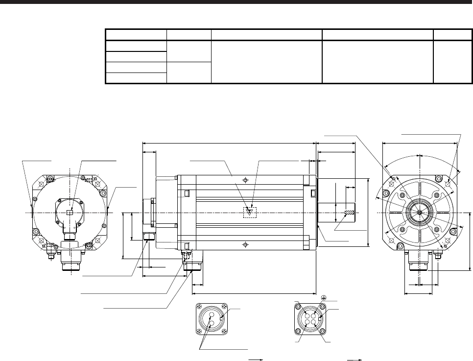
8. HG-JR SERIES
8 - 46
Model Output [kW] Brake static friction torque [N•m] Moment of inertia J [× 10-4 kg•m2] Mass [kg]
HG-JR12K1B 12
126 336 97
HG-JR12K14B
HG-JR15K1MB 15
HG-JR15K1M4B
[Unit: mm]
82
4 54
171.1
□220
45°
37.5°
2-M8 screw
φ270
φ250
φ235
Caution
plate
Caution plate
φ200h7
27
M10 screw
Oil seal
φ55m6
110
116
420
512
40
81
136.2
19.5
130
32
365.5
Motor plate
(Opposite side)
Power supply connector
MS3102A32-17P
Electromagnetic brake connector
MS3102A10SL-4P
Encoder connector
MS3102A20-29P
Motor plate
4-φ13.5 mounting hole
Use hexagon socket
head cap screw.
U
W
V
B
C
A
D
Power supply connector
Motor flange direction
Key
B
A
Electromagnetic brake connector
Motor flange direction
Electromagnetic
brake
Caution plate
Key
(PE)
(Note) *3,*4
(Note) *1,*2
(Note)
*3
(Note)
*2
(Note)
*1
(Note)
*4
Bottom
Top
Top
Bottom
Top
Bottom
Top
BC42636A BC42647A BC43508* BC43509*
Bottom
Note. *1, *2, *3, and *4 are screw hole for eyebolt (M10).
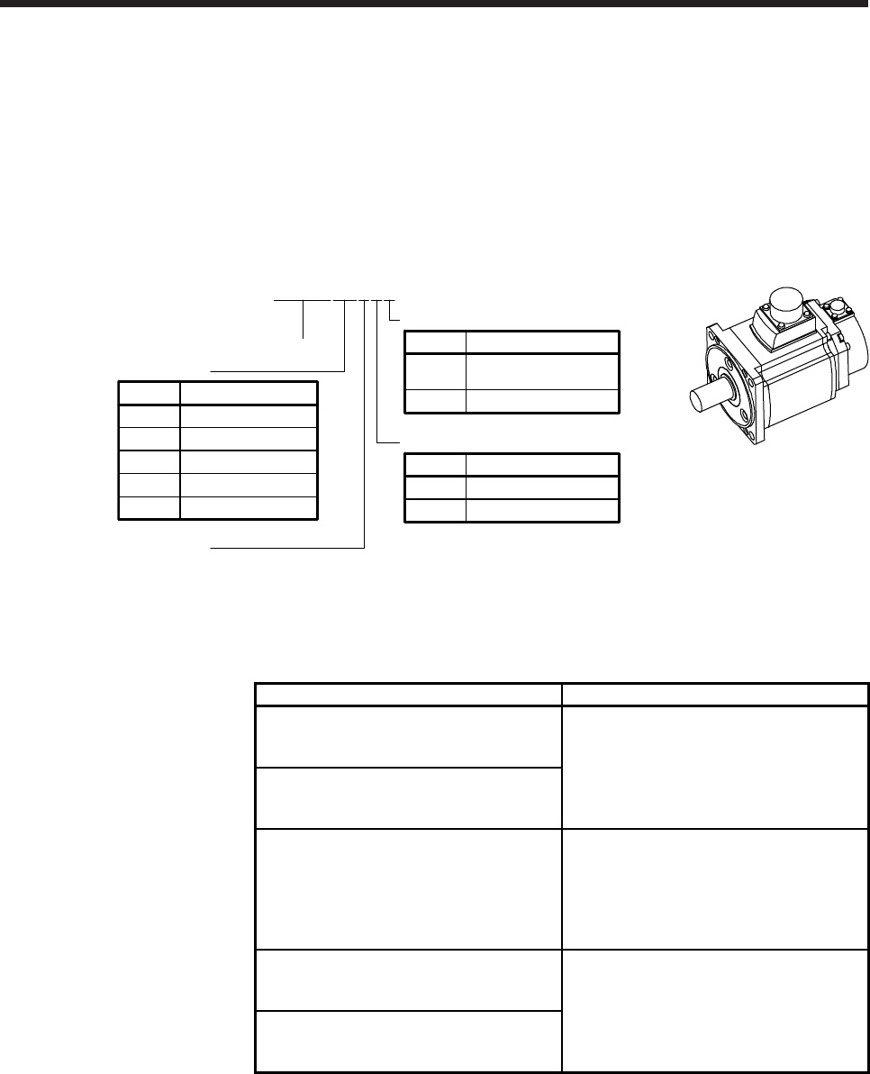
9. HG-RR SERIES
9 - 1
9. HG-RR SERIES
This chapter provides information on the servo motor specifications and characteristics. When using the HG-
RR series servo motor, always read the Safety Instructions in the beginning of this manual and chapters 1 to
5, in addition to this chapter.
9.1 Model designation
The following describes model designation. Not all combinations of the symbols are available.
HG-RR103BK
Shaft type
Symbol Shaft shape
None Standard
(straight shaft)
K(Note) Keyway shaft
Series
Appearance
None None
Electromagnetic brake
Symbol Electromagnetic brake
BWith
Rated speed
3000 [r/min]
10 1
Rated output
Symbol Rated output [kW]
15 1.5
20 2
35 3.5
50 5
Note. Key is not included.
9.2 Combination list of servo motors and servo amplifiers
Servo motor Servo amplifier
MR-J4-200A
HG-RR103 MR-J4-200A-RJ
MR-J4-200B
MR-J4-200B-RJ
HG-RR153 MR-J4-200B-RJ010
MR-J4-200B-RJ020
MR-J4-350A
MR-J4-350A-RJ
HG-RR203 MR-J4-350B
MR-J4-350B-RJ
MR-J4-350B-RJ010
MR-J4-350B-RJ020
MR-J4-500A
HG-RR353 MR-J4-500A-RJ
MR-J4-500B
MR-J4-500B-RJ
HG-RR503 MR-J4-500B-RJ010
MR-J4-500B-RJ020
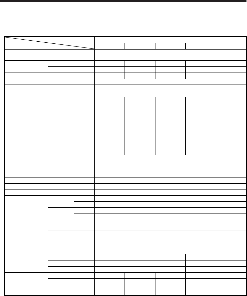
9. HG-RR SERIES
9 - 2
9.3 Standard specifications
9.3.1 Standard specifications list
Servo motor
Item
HG-RR series (ultra-low inertia/medium capacity)
103(B) 153(B) 203(B) 353(B) 503(B)
Power supply capacity Refer to "Power supply equipment capacity and generated loss of servo
amplifiers" in Servo Amplifier Instruction Manual.
Continuous running
duty (Note 1)
Rated output [kW] 1.0 1.5 2.0 3.5 5.0
Rated torque [N•m] 3.2 4.8 6.4 11.1 15.9
Maximum torque [N•m] 8.0 11.9 15.9 27.9 39.8
Rated speed (Note 1) [r/min] 3000
Maximum speed [r/min] 4500
Instantaneous permissible speed [r/min] 5175
Power rate at
continuous rated
torque
Standard [kW/s] 67.4 120 176 150 211
With an
electromagnetic brake
[kW/s]
54.8 101 153 105 163
Rated current [A] 6.1 8.8 14 23 28
Maximum current [A] 18 23 37 58 70
Moment of inertia J
Standard [× 10-4 kg•m2] 1.50 1.90 2.30 8.30 12.0
With an
electromagnetic brake
[× 10-4 kg•m2]
1.85 2.25 2.65 11.8 15.5
Recommended load to motor inertia ratio
(Note 2) 5 times or less
Speed/position detector 22-bit encoder common to absolute position/incremental
(resolution per servo motor revolution: 4194304 pulses/rev)
Oil seal With
Insulation class 155 (F)
Structure Totally-enclosed, natural-cooling (IP rating: IP65 (Note 3))
Environment (Note 4)
Ambient
temperature
Operation 0 ˚C to 40 ˚C (non-freezing)
Storage -15 ˚C to 70 ˚C (non-freezing)
Ambient
humidity
Operation 80 %RH or less (non-condensing)
Storage 90 %RH or less (non-condensing)
Ambience Indoors (no direct sunlight),
free from corrosive gas, flammable gas, oil mist, dust, and dirt
Altitude 1000 m or less above sea level
Vibration resistance
(Note 5) X, Y: 24.5 m/s2
Vibration rank (Note 6) V10
Permissible load for
the shaft (Note 7)
L [mm] 45 63
Radial [N] 686 980
Thrust [N] 196 392
Mass
Standard [kg] 3.9 5.0 6.2 12 17
With an
electromagnetic brake
[kg]
6.0 7.0 8.3 15 21
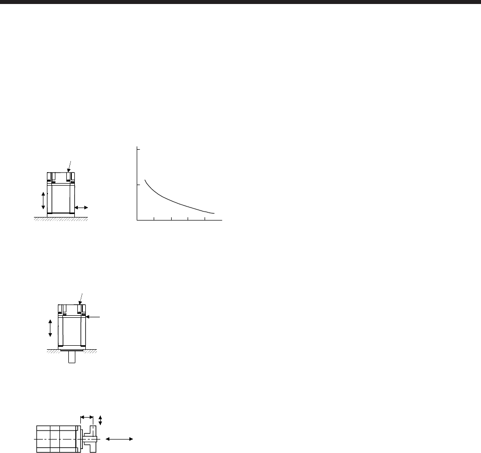
9. HG-RR SERIES
9 - 3
Note 1. When the power supply voltage drops, the output and the rated speed cannot be guaranteed.
2. If the load to motor inertia ratio exceeds the indicated value, contact your local sales office.
3. Except for the shaft-through portion. IP classifies the degrees of protection provided against the intrusion of solid objects and
water in electrical enclosures.
4. In the environment where the servo motor is exposed to oil mist, oil, or water, the servo motor of the standard specifications
may not be usable. Please contact your local sales office.
5. The following figure shows the vibration directions. The value is the one at the part that indicates the maximum value (normally
the opposite to load-side bracket). When the servo motor stops, fretting is likely to occur at the bearing. Therefore, suppress
the vibration to about half of the permissible value.
Y
X
Servo motor
Vibration
Speed [r/min]
0 1000 2000 3000 4000
10
100
1000
4500
Vibration amplitude
(both amplitudes) [μm]
6. V10 indicates that the amplitude of a single servo motor is 10 μm or less. The following figure shows the servo motor mounting
position for measurement and the measuring position.
Servo motor
Top
Bottom
Measuring position
7. The following shows permissible load for the shaft. Do not subject the shaft to load greater than the value in the specifications
list. The value assumes that the load is applied independently.
L
Radial load
Thrust load
L: Distance from flange mounting surface to load center
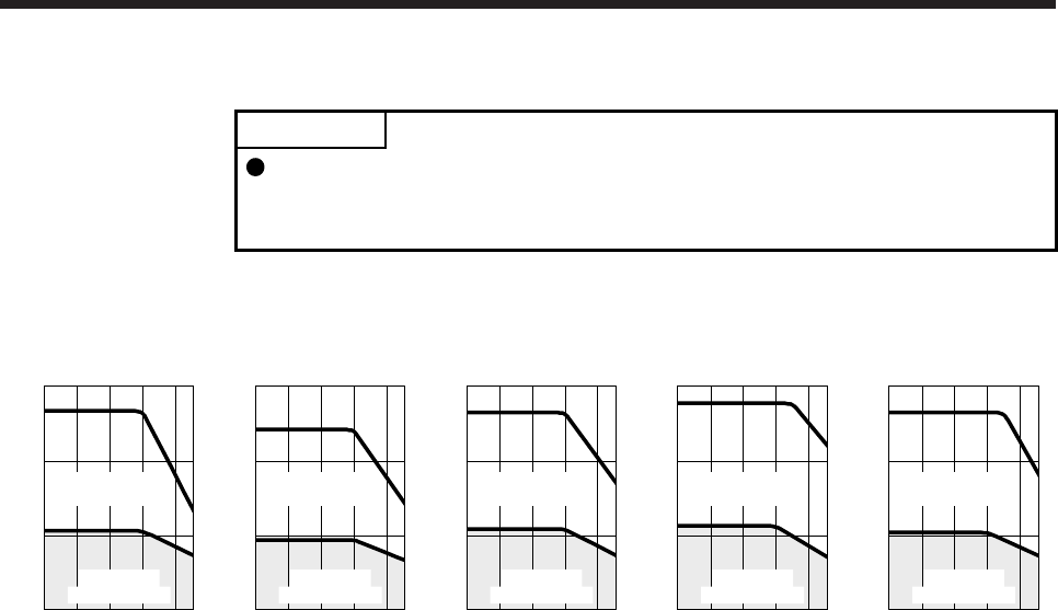
9. HG-RR SERIES
9 - 4
9.3.2 Torque characteristics
POINT
For the system where the unbalanced torque occurs, such as a vertical axis
system, the unbalanced torque of the machine should be kept at 70% or less of
the rated torque.
When the power supply input of the servo amplifier is 3-phase 200 V AC, the torque characteristic is
indicated by the heavy line.
[HG-RR103]
1000 2000 3000 4000 45000
0
3
6
9
Speed [r/min]
Continuous
running range
Short-duration
running range
Torque [N•m]
[HG-RR153]
Speed [r/min]
Continuous
running range
Short-duration
running range
Torque [N•m]
[H
1000 2000 3000 4000 45000
0
5
10
15
[HG-RR203]
1000 2000 3000 4000 45000
0
6
12
18
Speed [r/min]
Continuous
running range
Short-duration
running range
Torque [N•m]
[HG-RR353]
1000 2000 3000 4000 45000
0
10
20
30
Speed [r/min]
Continuous
running range
Short-duration
running range
Torque [N•m]
[HG-RR503]
1000 2000 3000 4000 45000
0
15
30
45
Speed [r/min]
Continuous
running range
Short-duration
running range
Torque [N•m]
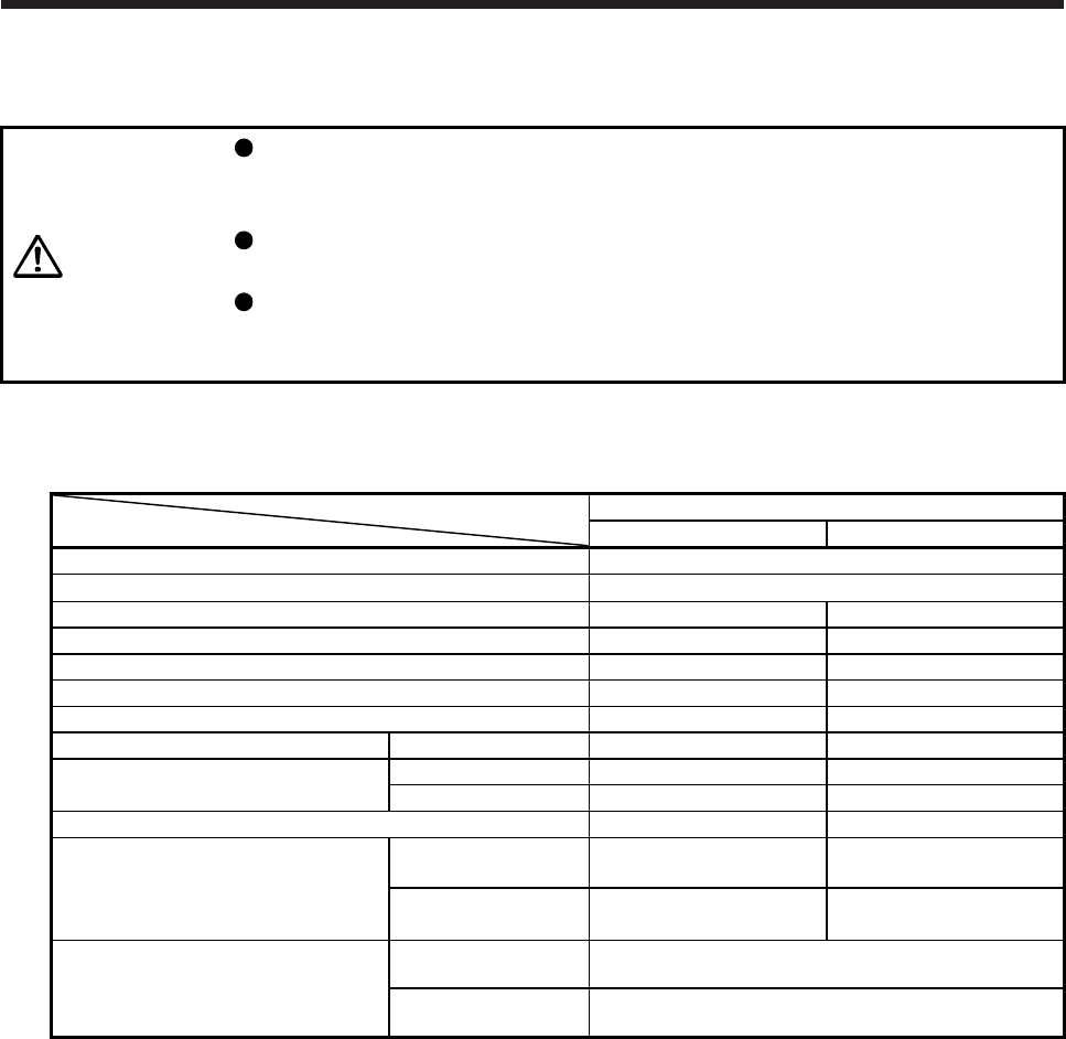
9. HG-RR SERIES
9 - 5
9.4 Electromagnetic brake characteristics
CAUTION
The electromagnetic brake is provided to prevent a drop at a power failure or
servo alarm occurrence during vertical drive or to hold a shaft at a stop. Do not
use it for normal braking (including braking at servo-lock).
Before operating the servo motor, be sure to confirm that the electromagnetic
brake operates properly.
The operation time of the electromagnetic brake differs depending on the power
supply circuit you use. Be sure to check the operation delay time with a real
machine.
The characteristics of the electromagnetic brake provided for the servo motor with an electromagnetic brake
are indicated below.
Servo motor
Item
HG-RR series
103B/153B/203B 353B/503B
Type (Note 1) Spring actuated type safety brake
Rated voltage (Note 4) 24 V DC 0
-10%
Power consumption [W] at 20 °C 19 23
Coil resistance (Note 6) [Ω] 30.0 25
Inductance (Note 6) [H] 0.81 0.70
Brake static friction torque [N•m] 7.0 17
Release delay time (Note 2) [s] 0.03 0.04
Braking delay time (Note 2) [s] DC off 0.03 0.03
Permissible braking work Per braking [J] 400 400
Per hour [J] 4000 4000
Brake looseness at servo motor shaft (Note 5) [degrees] 0.2 to 0.6 0.2 to 0.6
Brake life (Note 3)
Number of brakings
[times] 20000 20000
Work per braking
[J] 200 200
Selection example of surge absorbers to
be used (Note 7, 8)
For the suppressed
voltage 125 V TND20V-680KB
For the suppressed
voltage 350 V TND10V-221KB
Note 1. There is no manual release mechanism. When it is necessary to hand-turn the servo motor shaft for machine centering,
etc., use a separate 24 V DC power supply to release the brake electrically.
2. The value for initial on gap at 20 °C.
3. The brake gap will increase as the brake lining wears, but the gap is not adjustable.
The brake life indicated is the number of braking cycles after which adjustment will be required.
4.
A
lways prepare a power supply exclusively used for the electromagnetic brake.
5. These are design values. These are not guaranteed values.
6. These are measured values. These are not guaranteed values.
7. Select the electromagnetic brake control relay properly, considering the characteristics of the electromagnetic brake and
surge absorber. When you use a diode for a surge absorber, the electromagnetic braking time will be longer.
8. Manufactured by Nippon Chemi-Con Corporation.
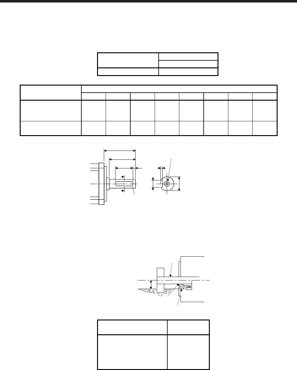
9. HG-RR SERIES
9 - 6
9.5 Servo motors with special shafts
The servo motors with special shafts indicated by the symbol (K) in the table are available. K is the symbol
attached to the servo motor model names.
Servo motor Shaft shape
Key shaft (without key)
HG-RR_(B)K K
Servo motor Variable dimensions
S R Q W QK QL U r
HG-RR103(B)K
HG-RR153(B)K
HG-RR203(B)K
24h6 45 40
80
-0.036 25 5
4
+0.2
0 4
HG-RR353(B)K
HG-RR503(B)K 28h6 63 58
80
-0.036 53 3
4
+0.2
0 4
QK
A
Q
R
A
QL U
W
r
M8 Depth 20
φ
Shaft section view A-A
S
9.6 Oil seal
The oil seal prevents the entry of oil into the servo motor.
Install the servo motor horizontally, and set the oil level in the gear box to be lower than the oil seal lip
always.
GearShaft
Servo motor
Oil seal
Height above oil level h
Lip
Servo motor Oil level h
[mm]
HG-RR103(B)
HG-RR153(B)
HG-RR203(B)
HG-RR353(B)
HG-RR503(B)
20
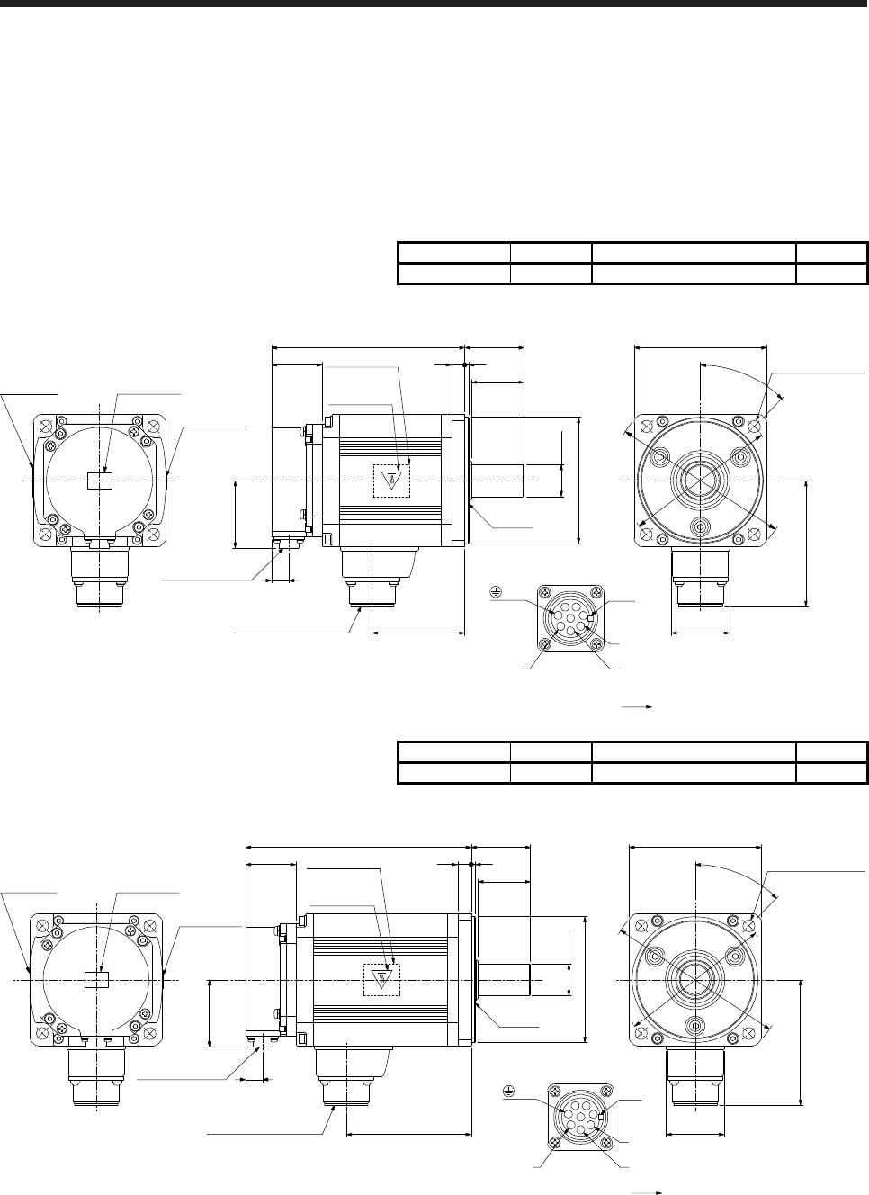
9. HG-RR SERIES
9 - 7
9.7 Dimensions
Moment of inertia on the table is the value calculated by converting the total value of moment of inertia for
servo motor and electromagnetic brake with servo motor shaft. The dimensions without tolerances are
general tolerance.
9.7.1 Standard (without an electromagnetic brake)
Model Output [kW] Moment of inertia J [× 10-4 kg•m2] Mass [kg]
HG-RR103 1.0 1.50 3.9
[Unit: mm]
38
145.5 45
40
310
□100
94.8
44
45°
50.9
69.5
φ115
φ135
φ95h7
φ24h6
Oil seal
Motor plate
(Opposite side)
Caution plate
Caution plateMotor plate
Caution plate
13Encoder connector
CMV1-R10P
Power supply connector
CE05-2A22-23P
4-φ9 mounting hole
Use hexagon socket
head cap screw.
Power supply connector
Motor flange direction
U
W
B
CA
D
Key
EF
G
H
V
Bottom
Top
Bottom
Top
Bottom
Top
Bottom
Top
(PE)
BC42648*
Model Output [kW] Moment of inertia J [× 10-4 kg•m2] Mass [kg]
HG-RR153 1.5 1.90 5.0
[Unit: mm]
38
170.5 45
40
310
50.9
94.5
13
φ95h7
Caution plateMotor plate
Caution plate
Motor plate
(Opposite side)
Caution plate
φ24h6
□100
94.8
44
45°
φ115
φ135
4-φ9 mounting hole
Use hexagon socket
head cap screw.
Encoder connector
CMV1-R10P
Power supply connector
CE05-2A22-23P
Oil seal
Bottom
Top
Bottom
Top
Bottom
Top
Bottom
Top
Power supply connector
Motor flange direction
U
W
B
CA
D
Key
EF
G
H
V
(PE)
BC42649*
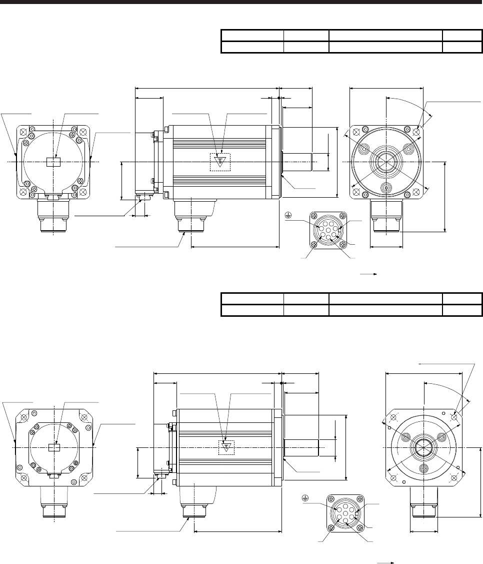
9. HG-RR SERIES
9 - 8
Model Output [kW] Moment of inertia J [× 10-4 kg•m2] Mass [kg]
HG-RR203 2.0 2.30 6.2
[Unit: mm]
38
195.5 45
40
310
50.9
119.5
13
φ95h7
φ24h6
Caution plateMotor plate
Caution plate
Bottom
Top
Bottom
Top
Bottom
Top
□100
94.8
44
45°
φ115
φ135
Bottom
Top
Encoder connector
CMV1-R10P
Power supply connector
CE05-2A22-23P
Motor plate
(Opposite side)
Caution plate
4-φ9 mounting hole
Use hexagon socket
head cap screw.
Oil seal
Power supply connector
Motor flange direction
U
W
B
CA
D
Key
EF
G
H
V
(PE)
BC42650*
Model Output [kW] Moment of inertia J [× 10-4 kg•m2] Mass [kg]
HG-RR353 3.5 8.30 12
[Unit: mm]
φ110h7
58
63
147.5
215.5
117.4
φ165
φ145
45°
46
□130
φ28h6
13
50.9
38.2 12 3
Caution plateMotor plate
Caution plate
Bottom
Top
Bottom
Top
Bottom
Top
Bottom
Top
Encoder connector
CMV1-R10P
Power supply connector
CE05-2A24-10P
Motor plate
(Opposite side)
Caution plate
Oil seal
4-φ9 mounting hole
Use hexagon socket
head cap screw.
Power supply connector
Motor flange direction
U
W
Key
V
EFD
CBA
G
(PE)
BC42651*
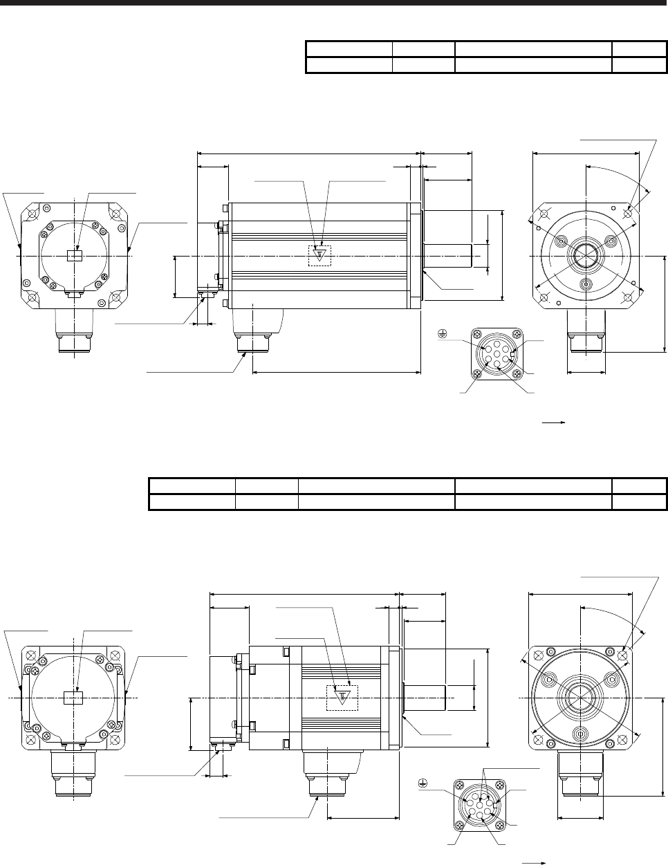
9. HG-RR SERIES
9 - 9
Model Output [kW] Moment of inertia J [× 10-4 kg•m2] Mass [kg]
HG-RR503 5.0 12.0 17
[Unit: mm]
φ110h7
58
63
204.5
272.5
φ28h6
13
50.9
38.2 12 3
117.4
φ165
φ145
45°
46
□130
Caution plateMotor plate
Caution plate
Encoder connector
CMV1-R10P
Power supply connector
CE05-2A24-10P
Motor plate
(Opposite side)
Caution plate
Oil seal
Bottom
Top
Bottom
Top
Bottom
T
op
Bottom
Top
Power supply connector
Motor flange direction
U
W
Key
V
EFD
CBA
G
4-φ9 mounting hole
Use hexagon socket
head cap screw.
(PE)
BC42652*
9.7.2 With an electromagnetic brake
Model Output [kW] Brake static friction torque [N•m] Moment of inertia J [× 10-4 kg•m2] Mass [kg]
HG-RR103B 1.0 7.0 1.85 6.0
[Unit: mm]
38
183 45
40
310
□100
94.8
44
45°
50.9
69.5
13
φ115
φ135
φ95h7
φ24h6
Motor plate
(Opposite side)
Caution plate
Caution plateMotor plate
Caution plate
Power supply connector
Motor flange direction
U
W
B
CA
D
Key
EF
G
H
V
Oil seal
Power supply connector
CE05-2A22-23P
Encoder connector
CMV1-R10P
Electromagnetic
brake
Bottom
Top
Bottom
Top
Bottom
Top
Bottom
Top
4-φ9 mounting hole
Use hexagon socket
head cap screw.
(PE)
BC42653*
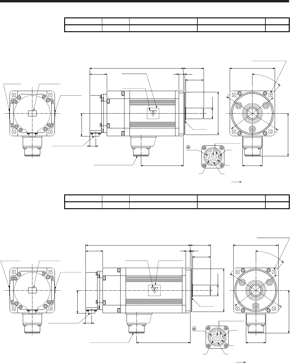
9. HG-RR SERIES
9 - 10
Model Output [kW] Brake static friction torque [N•m] Moment of inertia J [× 10-4 kg•m2] Mass [kg]
HG-RR153B 1.5 7.0 2.25 7.0
[Unit: mm]
38
208 45
40
310
50.9
94.5
φ95h7
φ24h6
□100
94.8
44
45°
φ115
φ135
Caution plateMotor plate
Caution plate
13
Encoder connector
CMV1-R10P
Power supply connector
CE05-2A22-23P
Motor plate
(Opposite side)
Caution plate
Oil seal
Bottom
Top
Bottom
Top
Bottom
T
op
Bottom
Top
4-φ9 mounting hole
Use hexagon socket
head cap screw.
Power supply connector
Motor flange direction
U
W
B
CA
D
Key
EF
G
H
V
Electromagnetic
brake
(PE)
BC42654*
Model Output [kW] Brake static friction torque [N•m] Moment of inertia J [× 10-4 kg•m2] Mass [kg]
HG-RR203B 2.0 7.0 2.65 8.3
[Unit: mm]
38
233 45
40
3
50.9
119.5
13
φ95h7
φ24h6
□100
94.8
44
45°
φ115
φ135
Caution plateMotor plate
Caution plate
Encoder connector
CMV1-R10P
Power supply connector
CE05-2A22-23P
Motor plate
(Opposite side)
Caution plate
Oil seal
Bottom
Top
Bottom
Top
Bottom
T
op
Bottom
Top
4-φ9 mounting hole
Use hexagon socket
head cap screw.
Power supply connector
Motor flange direction
U
W
B
CA
D
Key
EF
G
H
V
Electromagnetic
brake
10
(PE)
BC42655*
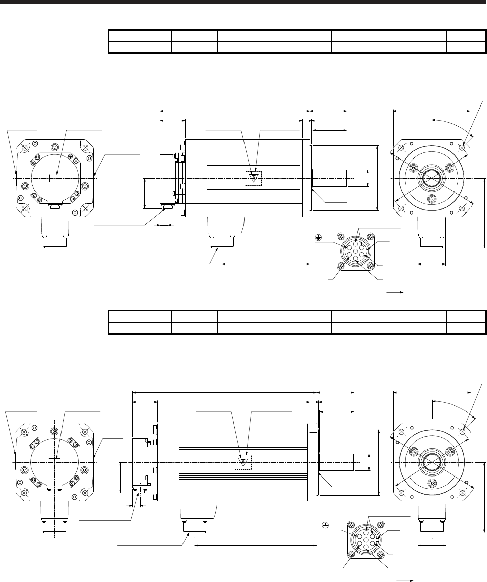
9. HG-RR SERIES
9 - 11
Model Output [kW] Brake static friction torque [N•m] Moment of inertia J [× 10-4 kg•m2] Mass [kg]
HG-RR353B 3.5 17 11.8 15
[Unit: mm]
φ110h7
58
63
147.5
252
φ28h6
13
50.9
42 12 3
117.4
φ165
φ145
45°
46
□130
Caution plateMotor plate
Caution plate
Power supply connector
CE05-2A24-10P
Encoder connector
CMV1-R10P
Motor plate
(Opposite side)
Caution plate
Oil seal
Bottom
Top
Bottom
Top
Bottom
Top
Bottom
Top
4-φ9 mounting hole
Use hexagon socket
head cap screw.
Electromagnetic
brake
Power supply connector
Motor flange direction
U
W
Key
V
EFD
CBA
G
(PE)
BC42656*
Model Output [kW] Brake static friction torque [N•m] Moment of inertia J [× 10-4 kg•m2] Mass [kg]
HG-RR503B 5.0 17 15.5 21
[Unit: mm]
φ110h7
58
63
204.5
309
φ28h6
13
50.9
42 12 3
117.4
φ165
φ145
45°
46
□130
Caution plateMotor plate
Caution
plate
Motor plate
(Opposite side)
Caution plate
Power supply connector
CE05-2A24-10P
Oil seal
Encoder connector
CMV1-R10P
Bottom
Top
Bottom
Top
Bottom
T
op
Bottom
Top
4-φ9 mounting hole
Use hexagon socket
head cap screw.
Electromagnetic
brake
Power supply connector
Motor flange direction
U
W
Key
V
EFD
CBA
G
(PE)
BC42657*

9. HG-RR SERIES
9 - 12
MEMO
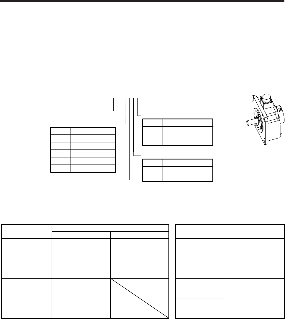
10. HG-UR SERIES
10 - 1
10. HG-UR SERIES
This chapter provides information on the servo motor specifications and characteristics. When using the HG-
UR series servo motor, always read the Safety Instructions in the beginning of this manual and chapters 1 to
5, in addition to this chapter.
10.1 Model designation
The following describes model designation. Not all combinations of the symbols are available.
Shaft type
Symbol Shaft shape
None Standard
(straight shaft)
K (Note) Keyway shaft
Series
Appearance
None None
Electromagnetic brake
Symbol Electromagnetic brake
BWith
Rated speed
2000 [r/min]
Rated output
Symbol Rated output [kW]
7 0.75
15 1.5
20 2
35 3.5
50 5
HG-UR 7 2 B K
Note. Key is not included.
10.2 Combination list of servo motors and servo amplifiers
Servo motor Servo amplifier Servo motor Servo amplifier
MR-J4 1-axis MR-J4 2-axis
HG-UR72
MR-J4-70A
MR-J4-70A-RJ
MR-J4-70B
MR-J4-70B-RJ
MR-J4-70B-RJ010
MR-J4-70B-RJ020
MR-J4W2-77B
MR-J4W2-1010B HG-UR202
MR-J4-350A
MR-J4-350A-RJ
MR-J4-350B
MR-J4-350B-RJ
MR-J4-350B-RJ010
MR-J4-350B-RJ020
HG-UR152
MR-J4-200A
MR-J4-200A-RJ
MR-J4-200B
MR-J4-200B-RJ
MR-J4-200B-RJ010
MR-J4-200B-RJ020
HG-UR352
MR-J4-500A
MR-J4-500A-RJ
MR-J4-500B
HG-UR502
MR-J4-500B-RJ
MR-J4-500B-RJ010
MR-J4-500B-RJ020
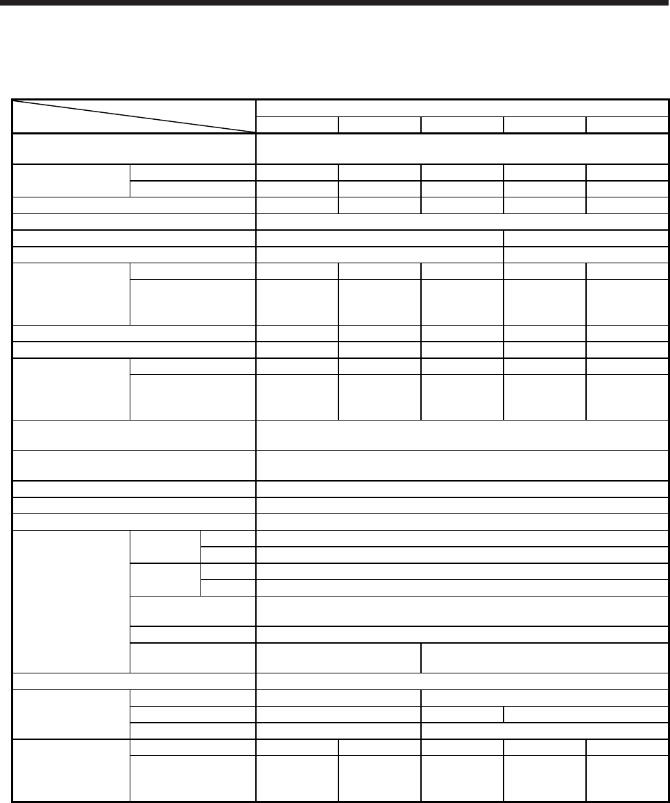
10. HG-UR SERIES
10 - 2
10.3 Standard specifications
10.3.1 Standard specifications list
Servo motor
Item
HG-UR 2000 r/min series (flat type/medium capacity)
72(B) 152(B) 202(B) 352(B) 502(B)
Power supply capacity Refer to "Power supply equipment capacity and generated loss of servo
amplifiers" in Servo Amplifier Instruction Manual.
Continuous running
duty (Note 1)
Rated output [kW] 0.75 1.5 2.0 3.5 5.0
Rated torque [N•m] 3.6 7.2 9.5 16.7 23.9
Maximum torque [N•m] 10.7 21.5 28.6 50.1 71.6
Rated speed (Note 1) [r/min] 2000
Maximum speed [r/min] 3000 2500
Instantaneous permissible speed [r/min] 3450 2875
Power rate at
continuous rated
torque
Standard [kW/s] 12.3 23.2 23.9 36.5 49.6
With an
electromagnetic brake
[kW/s]
10.3 21.2 19.5 32.8 46.0
Rated current [A] 5.4 9.7 14 23 28
Maximum current [A] 16 29 42 69 84
Moment of inertia J
Standard [× 10-4 kg•m2] 10.4 22.1 38.2 76.5 115
With an
electromagnetic brake
[× 10-4 kg•m2]
12.5 24.2 46.8 85.1 124
Recommended load to motor inertia ratio
(Note 2) 15 times or less
Speed/position detector 22-bit encoder common to absolute position/incremental
(resolution per servo motor revolution: 4194304 pulses/rev)
Oil seal With
Insulation class 155 (F)
Structure Totally-enclosed, natural-cooling (IP rating: IP65 (Note 3))
Environment (Note 4)
Ambient
temperature
Operation 0 ˚C to 40 ˚C (non-freezing)
Storage -15 ˚C to 70 ˚C (non-freezing)
Ambient
humidity
Operation 80 %RH or less (non-condensing)
Storage 90 %RH or less (non-condensing)
Ambience Indoors (no direct sunlight),
free from corrosive gas, flammable gas, oil mist, dust, and dirt
Altitude 1000 m or less above sea level
Vibration resistance
(Note 5) X, Y: 24.5 m/s2 X: 24.5 m/s2 Y: 49 m/s2
Vibration rank (Note 6) V10
Permissible load for
the shaft (Note 7)
L [mm] 55 65
Radial [N] 637 882 1176
Thrust [N] 490 784
Mass
Standard [kg] 8.0 11 16 20 24
With an
electromagnetic brake
[kg]
10 13 22 26 30
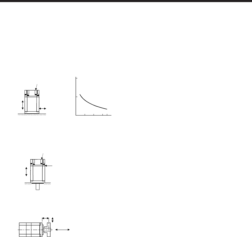
10. HG-UR SERIES
10 - 3
Note 1. When the power supply voltage drops, the output and the rated speed cannot be guaranteed.
2. If the load to motor inertia ratio exceeds the indicated value, contact your local sales office.
3. Except for the shaft-through portion. IP classifies the degrees of protection provided against the intrusion of solid objects and
water in electrical enclosures.
4. In the environment where the servo motor is exposed to oil mist, oil, or water, the servo motor of the standard specifications
may not be usable. Please contact your local sales office.
5. The following figure shows the vibration directions. The value is the one at the part that indicates the maximum value (normally
the opposite to load-side bracket). When the servo motor stops, fretting is likely to occur at the bearing. Therefore, suppress
the vibration to about half of the permissible value.
Y
X
Servo motor
Vibration
Speed [r/min]
0 1000 2000 30003450
10
100
1000
Vibration amplitude
(both amplitudes) [μm]
6. V10 indicates that the amplitude of a single servo motor is 10 μm or less. The following figure shows the servo motor mounting
position for measurement and the measuring position.
Servo motor
Top
Bottom
Measuring position
7. The following shows permissible load for the shaft. Do not subject the shaft to load greater than the value in the specifications
list. The value assumes that the load is applied independently.
L
Radial load
Thrust load
L: Distance from flange mounting surface to load center
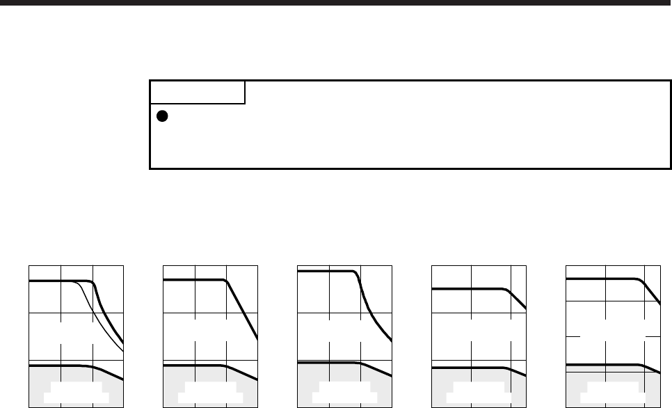
10. HG-UR SERIES
10 - 4
10.3.2 Torque characteristics
POINT
For the system where the unbalanced torque occurs, such as a vertical axis
system, the unbalanced torque of the machine should be kept at 70% or less of
the rated torque.
When the power supply input of the servo amplifier is 3-phase 200 V AC or 1-phase 230 V AC, the torque
characteristic is indicated by the heavy line. For the 1-phase 200 V AC power supply, part of the torque
characteristic is indicated by the thin line. HG-UR72 supports 1-phase power supply input.
[HG-UR72]
1000 2000 30000
0
4
8
12
Speed [r/min]
Continuous
running range
Short-duration
running range
Torque [N•m]
[HG-UR152]
1000 2000 30000
0
8
16
24
Speed [r/min]
Continuous
running range
Short-duration
running range
Torque [N•m]
[HG-UR202]
1000 2000 30000
0
10
20
30
Speed [r/min]
Continuous
running range
Short-duration
running range
Torque [N•m]
[HG-UR352]
1000 2000 25000
0
20
40
60
Speed [r/min]
Continuous
running range
Short-duration
running range
Torque [N•m]
[HG-UR502]
1000 2000 25000
0
20
40
80
60
Speed [r/min]
Continuous
running range
Short-duration
running range
Torque [N•m]
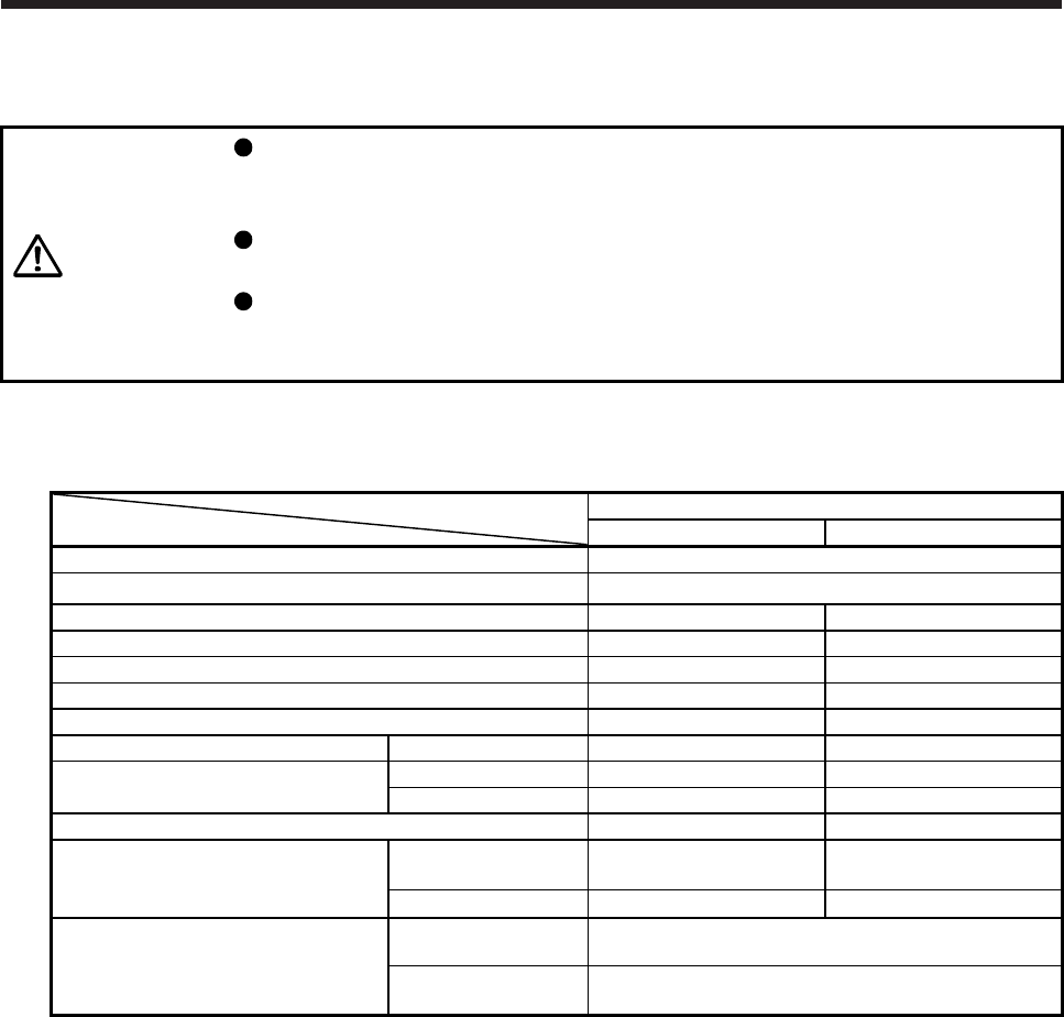
10. HG-UR SERIES
10 - 5
10.4 Electromagnetic brake characteristics
CAUTION
The electromagnetic brake is provided to prevent a drop at a power failure or
servo alarm occurrence during vertical drive or to hold a shaft at a stop. Do not
use it for normal braking (including braking at servo-lock).
Before operating the servo motor, be sure to confirm that the electromagnetic
brake operates properly.
The operation time of the electromagnetic brake differs depending on the power
supply circuit you use. Be sure to check the operation delay time with a real
machine.
The characteristics of the electromagnetic brake provided for the servo motor with an electromagnetic brake
are indicated below.
Servo motor
Item
HG-UR series
72B/152B 202B/352B/502B
Type (Note 1) Spring actuated type safety brake
Rated voltage (Note 4) 24 V DC 0
-10%
Power consumption [W] at 20 °C 19 34
Coil resistance (Note 6) [Ω] 29.0 17.0
Inductance (Note 6) [H] 0.8 1.17
Brake static friction torque [N•m] 8.5 44
Release delay time (Note 2) [s] 0.04 0.1
Braking delay time (Note 2) [s] DC off 0.03 0.03
Permissible braking work Per braking [J] 400 4500
Per hour [J] 4000 45000
Brake looseness at servo motor shaft (Note 5) [degrees] 0.2 to 0.6 0.2 to 0.6
Brake life (Note 3)
Number of brakings
[times] 20000 20000
Work per braking [J] 200 1000
Selection example of surge absorbers to
be used (Note 7, 8)
For the suppressed
voltage 125 V TND20V-680KB
For the suppressed
voltage 350 V TND10V-221KB
Note 1. There is no manual release mechanism. When it is necessary to hand-turn the servo motor shaft for machine centering,
etc., use a separate 24 V DC power supply to release the brake electrically.
2. The value for initial on gap at 20 °C.
3. The brake gap will increase as the brake lining wears, but the gap is not adjustable.
The brake life indicated is the number of braking cycles after which adjustment will be required.
4.
A
lways prepare a power supply exclusively used for the electromagnetic brake.
5. These are design values. These are not guaranteed values.
6. These are measured values. These are not guaranteed values.
7. Select the electromagnetic brake control relay properly, considering the characteristics of the electromagnetic brake and
surge absorber. When you use a diode for a surge absorber, the electromagnetic braking time will be longer.
8. Manufactured by Nippon Chemi-Con Corporation.
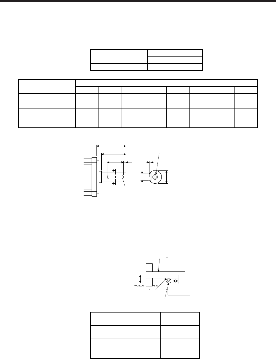
10. HG-UR SERIES
10 - 6
10.5 Servo motors with special shafts
The servo motors with special shafts indicated by the symbol (K) in the table are available. K is the symbol
attached to the servo motor model names.
Servo motor Shaft shape
Key shaft (without key)
HG-UR_(B)K K
Servo motor Variable dimensions
S R Q W QK QL U r
HG-UR72(B)K 22h6 55 50
60
-0.036 42 3
3.5+0.1
0 3
HG-UR152(B)K 28h6 55 50
80
-0.036 40 3
4
+0.2
0 4
HG-UR202(B)K
HG-UR352(B)K
HG-UR502(B)K
35 +0.010
0 65 60
10 0
-0.036 50 5
5+0.2
0 5
QK
A
Q
R
A
QL U
W
r
M8 Depth 20
φ
Shaft section view A-A
S
10.6 Oil seal
The oil seal prevents the entry of oil into the servo motor.
Install the servo motor horizontally, and set the oil level in the gear box to be lower than the oil seal lip
always.
GearShaft
Servo motor
Oil seal
Height above oil level h
Lip
Servo motor Oil level h
[mm]
HG-UR72(B)
HG-UR152(B) 20
HG-UR202(B)
HG-UR352(B)
HG-UR502(B)
25
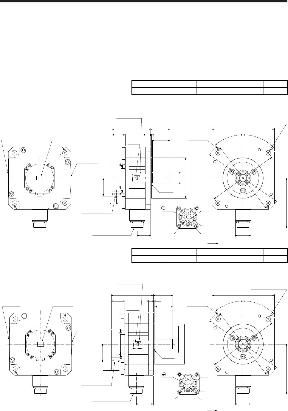
10. HG-UR SERIES
10 - 7
10.7 Dimensions
Moment of inertia on the table is the value calculated by converting the total value of moment of inertia for
servo motor and electromagnetic brake with servo motor shaft.
The dimensions without tolerances are general tolerance.
10.7.1 Standard (without an electromagnetic brake)
Model Output [kW] Moment of inertia J [× 10-4 kg•m2] Mass [kg]
HG-UR72 0.75 10.4 8.0
[Unit: mm]
38
141.3
50.9
13
109 55
50
3
38
φ22h6
φ114.3 0
-0.025
φ200
φ230
φ215
44
Bottom
Top
Bottom
Top
Bottom
Top
13
Motor plate Caution plate
Caution plate
□176
45°
40°
2-M6 screw
4-φ13.5 mounting hole
Use hexagon socket
head cap screw.
Oil seal
Power supply connector
CE05-2A22-23P
Encoder connector
CMV1-R10P
Motor plate
(Opposite side)
Caution
plate
Power supply connector
Motor flange direction
U
W
B
CA
D
Key
EF
G
H
V
(PE)
BC42658*
Bottom
Top
Model Output [kW] Moment of inertia J [× 10-4 kg•m2] Mass [kg]
HG-UR152 1.5 22.1 11
[Unit: mm]
38
141.3
50.9
13
118.5 55
50
3
47.5
φ28h6
φ114.3 0
-0.025
φ200
φ230
φ215
44
13
□176
45°
40°
2-M6 screw
4-φ13.5 mounting hole
Use hexagon socket
head cap screw.
Oil seal
Power supply connector
CE05-2A22-23P
Encoder connector
CMV1-R10P
Top
Motor plate
(Opposite side)
Caution
plate
Bottom
Top
Bottom
Top
Bottom
Top
Motor plate Caution plate
Caution plate
Power supply connector
Motor flange direction
U
W
B
CA
D
Key
EF
G
H
V
(PE)
BC42659*
Bottom
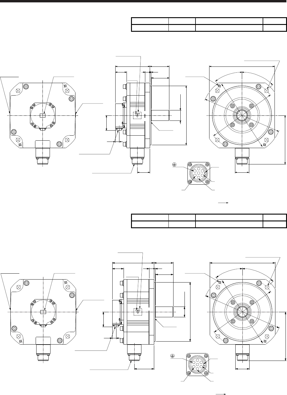
10. HG-UR SERIES
10 - 8
Model Output [kW] Moment of inertia J [× 10-4 kg•m2] Mass [kg]
HG-UR202 2.0 38.2 16
[Unit: mm]
38
116.5
4
65
60
φ35+0.010
0
φ200 0
-0.046
42.5
50.9
13
16
□220
164.9
45°
37.5°
φ235
φ250
φ270
47
2-M8 screw
4-φ13.5 mounting hole
Use hexagon socket
head cap screw.
Caution plateMotor plate
Caution plate
Bottom
Top
Bottom
Top
Bottom
Top
Encoder connector
CMV1-R10P
Power supply connector
CE05-2A24-10P
Motor plate
(Opposite side)
Caution
plate
Oil seal
Power supply connector
Motor flange direction
U
W
Key
V
EFD
CBA
G
(PE)
BC42660*
Bottom
Top
Model Output [kW] Moment of inertia J [× 10-4 kg•m2] Mass [kg]
HG-UR352 3.5 76.5 20
[Unit: mm]
38
140.5
4
65
60
φ35+0.010
0
φ200 0
-0.046
66.5
50.9
13
16
□220
164.9
45°
37.5°
φ235
φ250
φ270
47
2-M8 screw
4-φ13.5 mounting hole
Use hexagon socket
head cap screw.
Caution plateMotor plate
Caution plate
Bottom
Top
Bottom
Top
Bottom
Top
Encoder connector
CMV1-R10P
Power supply connector
CE05-2A24-10P
Top
Motor plate
(Opposite side)
Caution
plate
Oil seal
Power supply connector
Motor flange direction
U
W
Key
V
EFD
CBA
G
(PE)
BC42661*
Bottom
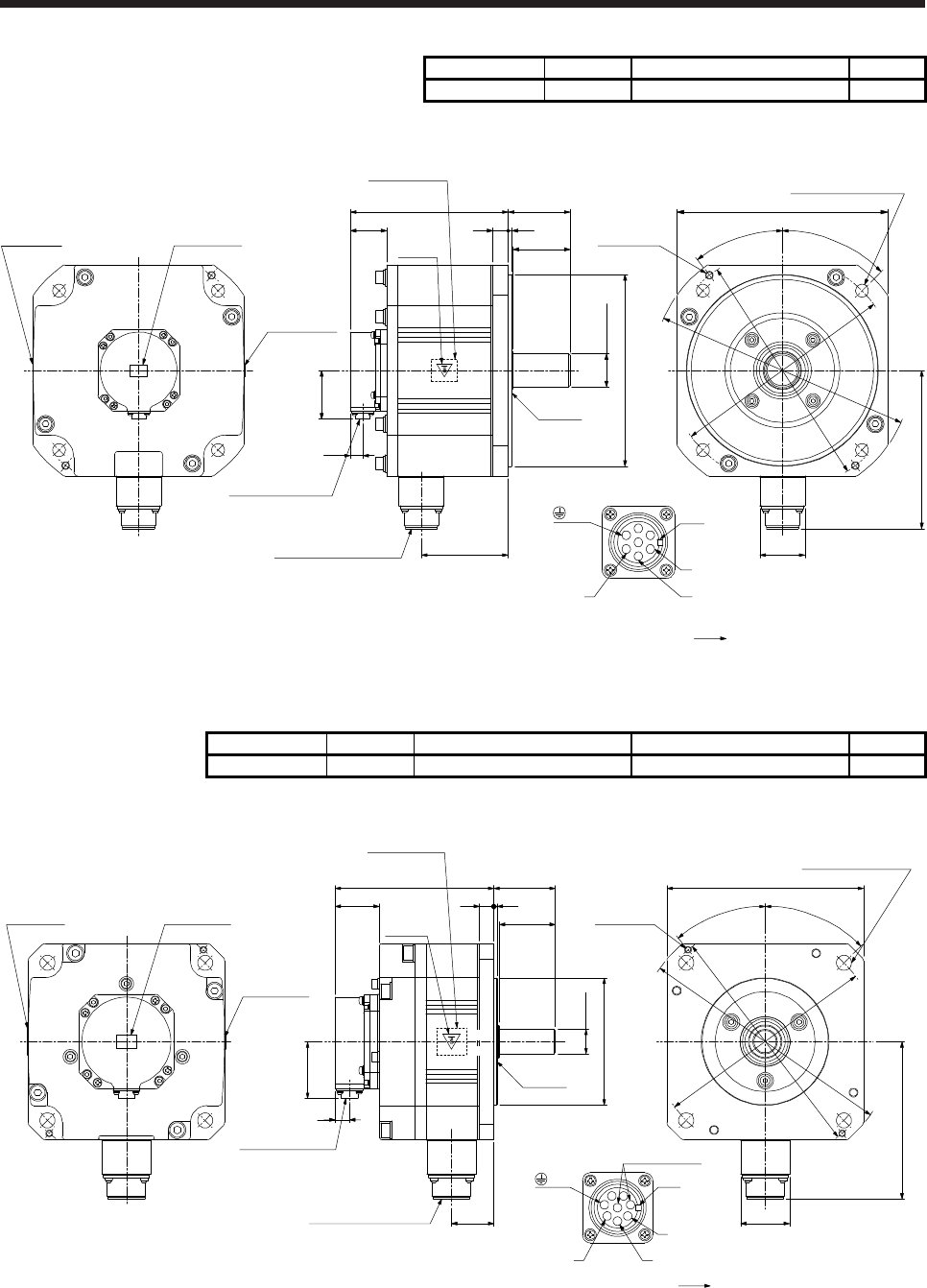
10. HG-UR SERIES
10 - 9
Model Output [kW] Moment of inertia J [× 10-4 kg•m2] Mass [kg]
HG-UR502 5.0 115 24
[Unit: mm]
38
164.5
4
65
60
φ35 +0.010
0
φ200 0
-0.046
90.5
50.9
13
16
□220
164.9
45°
37.5°
φ235
φ250
φ270
47
2-M8 screw
4-φ13.5 mounting hole
Use hexagon socket
head cap screw.
Caution plateMotor plate
Caution plate
Bottom
Top
Bottom
Top
Bottom
Top
Encoder connector
CMV1-R10P
Power supply connector
CE05-2A24-10P
Bottom
Top
Motor plate
(Opposite side)
Caution
plate
Oil seal
Power supply connector
Motor flange direction
U
W
Key
V
EFD
CBA
G
(PE)
BC42662*
10.7.2 With an electromagnetic brake
Model Output [kW] Brake static friction torque [N•m] Moment of inertia J [× 10-4 kg•m2] Mass [kg]
HG-UR72B 0.75 8.5 12.5 10
[Unit: mm]
40
141.3
50.9
13
142.5 55
50
3
38
φ22h6
φ114.3 0
-0.025
φ200
φ230
φ215
44
13
Motor plate Caution plate
Caution plate
Motor plate
(Opposite side)
Caution
plate
□176
45°
40°
2-M6 screw
4-φ13.5 mounting hole
Use hexagon socket
head cap screw.
Encoder connector
CMV1-R10P
Power supply connector
CE05-2A22-23P
Oil seal
Bottom
Top
Bottom
Top
Bottom
Top
Power supply connector
Motor flange direction
U
W
B
CA
D
Key
EF
G
H
V
Electromagnetic
brake
(PE)
BC42663*
Bottom
Top
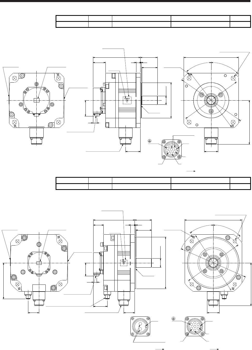
10. HG-UR SERIES
10 - 10
Model Output [kW] Brake static friction torque [N•m] Moment of inertia J [× 10-4 kg•m2] Mass [kg]
HG-UR152B 1.5 8.5 24.2 13
[Unit: mm]
40
□176
141.3
50.9
13
152 55
50
3
47.5
φ28h6
φ114.3 0
-0.025
45°
40°
φ200
φ230
φ215
44
Motor plate
(Opposite side)
Caution
plate 2-M6 screw
Motor plate Caution plate
Caution plate
13
Encoder connector
CMV1-R10P
Power supply connector
CE05-2A22-23P
4-φ13.5 mounting hole
Use hexagon socket
head cap screw.
Oil seal
Bottom
T
op
Bottom
Top
Bottom
Top Top
Power supply connector
Motor flange direction
U
W
B
CA
D
Key
EF
G
H
V
Electromagnetic
brake
(PE)
BC42664*
Bottom
Model Output [kW] Brake static friction torque [N•m] Moment of inertia J [× 10-4 kg•m2] Mass [kg]
HG-UR202B 2.0 44 46.8 22
[Unit: mm]
39.2
159.5
4
65
60
φ35+0.010
0
φ200 0
-0.046
42.5
13
50.9
42
138.7
53.5
Caution plateMotor plate
Caution plate
Bottom
Top
Motor plate
(Opposite side)
Caution
plate
Bottom
Top
Bottom
Top
16
B
A
Electromagnetic brake connector
Motor flange direction
Electromagnetic brake
Oil seal
Encoder connector
CMV1-R10P
Power supply connector
CE05-2A24-10P
Electromagnetic brake connector
MS3102A10SL-4P
□220
164.9
45°
37.5°
φ235
φ250
φ270
47
2-M8 screw
4-φ13.5 mounting hole
Use hexagon socket
head cap screw.
Power supply connector
Motor flange direction
U
W
Key
V
EFD
CBA
G
Key (PE)
BC42665*
Bottom
Top
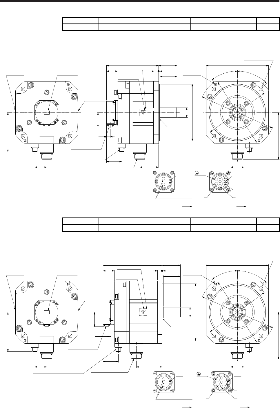
10. HG-UR SERIES
10 - 11
Model Output [kW] Brake static friction torque [N•m] Moment of inertia J [× 10-4 kg•m2] Mass [kg]
HG-UR352B 3.5 44 85.1 26
[Unit: mm]
39.2
183.5
4
65
60
66.5
50.9
Motor plate
(Opposite side)
Caution plate
16
□220
164.9
45°
37.5°
φ235
φ250
φ270
47
2-M8 screw
4-φ13.5 mounting hole
Use hexagon socket
head cap screw.
42
138.7
Caution plateMotor plate
Caution plate
Bottom
Top
Bottom
Top
Bottom
Top
Encoder connector
CMV1-R10P
Power supply connector
CE05-2A24-10P
Electromagnetic brake connector
MS3102A10SL-4P
13
53.5
φ35+0.010
0
φ200 0
-0.046
Oil seal
Top
B
A
Electromagnetic brake connector
Motor flange direction
Electromagnetic brake
Power supply connector
Motor flange direction
U
W
Key
V
EFD
CBA
G
Key (PE)
BC42666*
Bottom
Model Output [kW] Brake static friction torque [N•m] Moment of inertia J [× 10-4 kg•m2] Mass [kg]
HG-UR502B 5.0 44 124 30
[Unit: mm]
39.2
207.5
4
65
60
90.5
50.9
Motor plate
(Opposite side)
Caution plate
16
□220
164.9
45°
37.5°
φ235
φ250
φ270
47
2-M8 screw
4-φ13.5 mounting hole
Use hexagon socket
head cap screw.
42
138.7
Caution plate
Motor plate
Caution
plate
Bottom
Top
Bottom
Top
Bottom
Top
Encoder connector
CMV1-R10P
Power supply connector
CE05-2A24-10P
Electromagnetic brake connector
MS3102A10SL-4P
13
53.5
φ35+0.010
0
φ200 0
-0.046
Oil seal
Bottom
Top
B
A
Electromagnetic brake connector
Motor flange direction
Electromagnetic brake
Power supply connector
Motor flange direction
U
W
Key
V
EFD
CBA
G
Key (PE)
BC42667*

10. HG-UR SERIES
10 - 12
MEMO
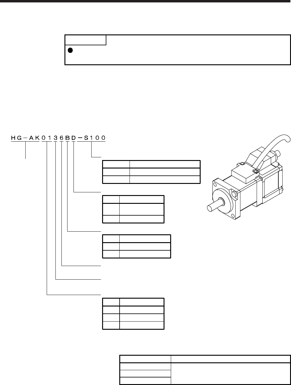
11. HG-AK SERIES
11 - 1
11. HG-AK SERIES
POINT
For combination with the MR-J3W-0303BN6 servo amplifier, refer to "Servo
Motor Instruction Manual (Vol. 2)" (SH(NA)030041).
This chapter provides information on the servo motor specifications and characteristics. When using the HG-
AK series servo motor, always read the Safety Instructions in the beginning of this manual and chapters 1 to
5, in addition to this chapter.
11.1 Model designation
The following describes model designation. Not all combinations of the symbols are available.
Appearance
Shaft type
Symbol Shaft shape
None Standard
(Straight shaft)
Rated speed
3000 [r/min]
None None
Electromagnetic brake
Symbol Electromagnetic brake
B With
01 10
Rated output
Symbol Rated output [W]
02 20
03 30
Series
Main circuit power supply voltage
48 V DC/24 V DC
D D-cut shaft
Encoder cable vertical lead
None Standard
Symbol Special specifications
-S100
Special specifications
11.2 Combination list of servo motors and servo amplifiers
Servo motor Servo amplifier
HG-AK0136 MR-J4-03A6(-RJ)
MR-J4W2-0303B6
HG-AK0236
HG-AK0336
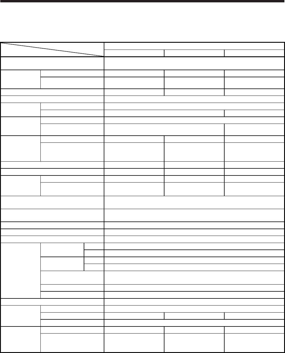
11. HG-AK SERIES
11 - 2
11.3 Standard specifications
11.3.1 Standard specifications list
Servo motor
Item
HG-AK series
0136(B) 0236(B) 0336(B)
Power supply capacity Refer to "Power supply equipment capacity and generated loss of servo amplifiers"
of each servo amplifier instruction manual.
Continuous
running duty
(Note 1)
Rated output [W] 10 20 30
Rated torque [N•m] 0.032 0.064 0.095
Maximum torque [N•m] 0.095 0.191 0.286
Rated speed (Note 1) [r/min] 3000
Maximum speed 48 V DC [r/min] 6000
24 V DC [r/min] 6000 5000
Instantaneous
permissible
speed
48 V DC [r/min] 6900
24 V DC [r/min] 6900 5750
Power rate at
continuous rated
torque
Standard [kW/s] 3.54 9.01 14.95
With
electromagnetic
brake
[kW/s] 2.41 6.99 12.32
Rated current [A] 2.1 2.1 2.2
Maximum current [A] 6.3 6.3 6.6
Moment of
inertia J
Standard [J × 10-4 kg•m2] 0.0029 0.0045 0.0061
With electromagnetic brake
[J × 10-4 kg•m2] 0.0042 0.0058 0.0074
Recommended load to motor inertia ratio
(Note 2) 30 times or less
Speed/position detector 18-bit encoder common to absolute position/incremental systems
(resolution per servo motor revolution: 262144 pulses/rev)
Oil seal None
Insulation class 130 (B)
Structure Totally enclosed, natural cooling (IP rating: IP55 (Note 3))
Environment
(Note 4)
Ambient
temperature
Operation 0 ˚C to 40 ˚C (non-freezing)
Storage -15 ˚C to 70 ˚C (non-freezing)
Ambient humidity Operation 80 %RH or less (non-condensing)
Storage 90 %RH or less (non-condensing)
Ambience Indoors (no direct sunlight),
free from corrosive gas, flammable gas, oil mist, dust, and dirt
Altitude 1000 m or less above sea level
Vibration resistance (Note 5) X, Y: 49 m/s2
Vibration rank (Note 6) V10
Permissible load
for the shaft
(Note 7)
L [mm] 16
Radial [N] 34 44 49
Thrust [N] 14
Mass
Standard [kg] 0.12 0.14 0.16
With
electromagnetic
brake
[kg] 0.22 0.24 0.26
Note 1. When the power supply voltage drops, the output and the rated speed cannot be guaranteed.
2. If the load to motor inertia ratio exceeds the indicated value, contact your local sales office.
3. The shaft-through portion, connector portion, and power supply cable outlet portion are excluded. IP classifies the degrees of
protection provided against the intrusion of solid objects and water in electrical enclosures.
4. In the environment where the servo motor is exposed to oil mist, oil, or water, the servo motor of the standard specifications
may not be usable. Please contact your local sales office.
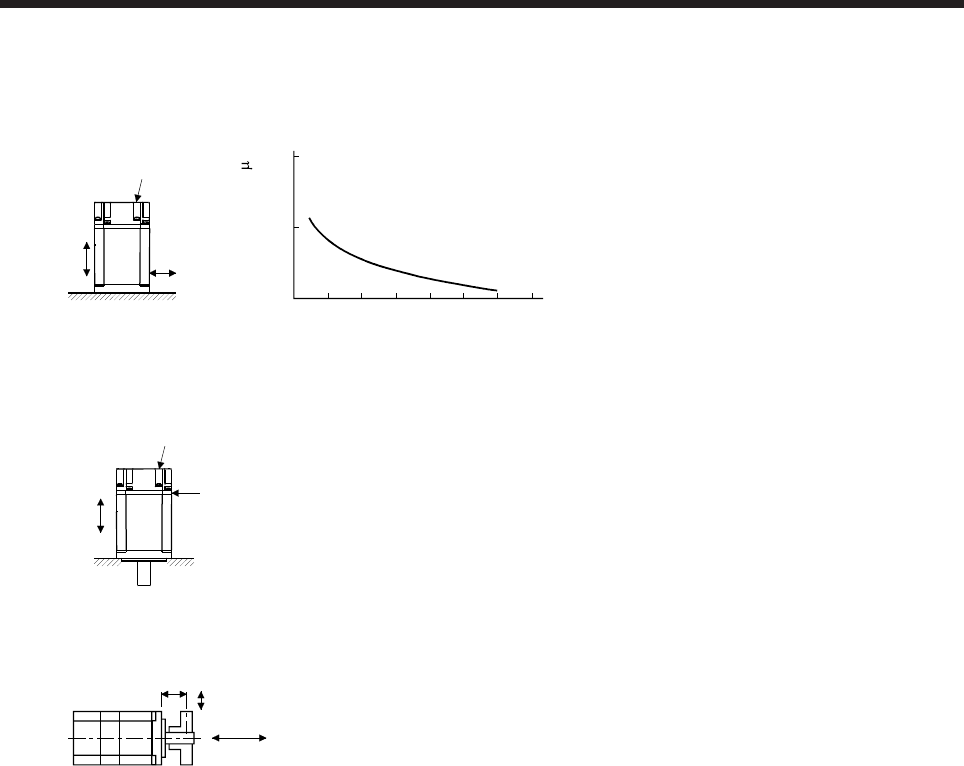
11. HG-AK SERIES
11 - 3
5. The following figure shows the vibration directions. The value is the one at the part that indicates the maximum value (normally
the opposite to load-side bracket). When the servo motor stops, fretting is likely to occur at the bearing. Therefore, suppress
the vibration to about half of the permissible value.
Y
X
Servo motor
Vibration
Speed [r/min]
0 1000 2000 3000 4000 5000 6000 7000
10
100
1000
Vibration amplitude
(both amplitudes) [ m]
6. V10 indicates that the amplitude of a single servo motor is 10 μm or less. The following figure shows the servo motor mounting
position for measurement and the measuring position.
Servo motor
Top
Bottom
Measuring position
7. The following shows permissible load for the shaft. Do not subject the shaft to load greater than the value in the specifications
list. The value assumes that the load is applied independently.
L
Radial load
Thrust load
L: Distance from flange mounting surface to load center
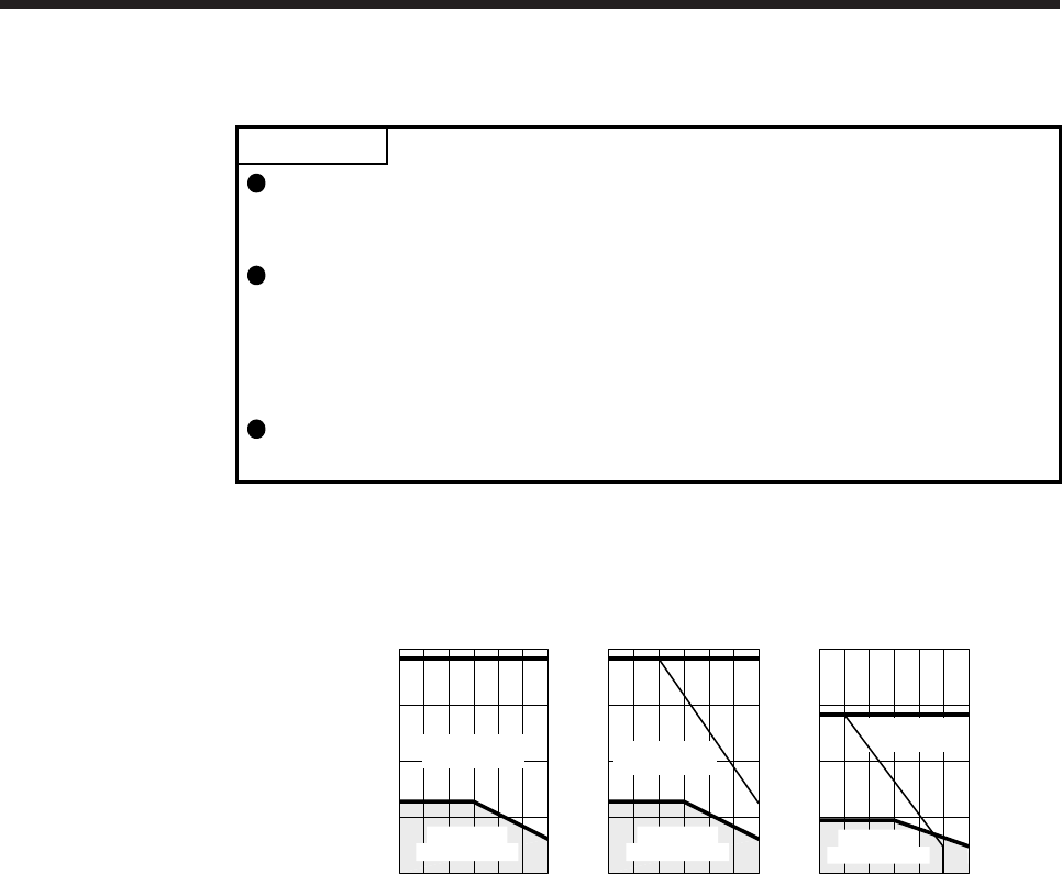
11. HG-AK SERIES
11 - 4
11.3.2 Torque characteristics
POINT
For the system where the unbalanced torque occurs, such as a vertical axis
system, the unbalanced torque of the machine should be kept at 70% or less of
the rated torque.
For the torque characteristics, MR-J4W03PWCBL5M-H or MR-
J4W03PWBRCBL5M-H was used for connecting servo amplifiers and servo
motors. When an optional cable longer than 5 m is used, the short-duration
running range in the torque characteristics may be lower because of voltage
drop.
When the main circuit power supply input of the servo amplifier is 24 V DC, the
maximum speed of HG-AK0336 will be 5000 r/min.
When the main circuit power supply input of the servo amplifier is 48 V DC, the torque characteristic is
indicated by the heavy line. For the 24 V DC power supply, part of the torque characteristic is indicated by
the thin line.
0
[HG-AK0136(B)]
Torque [N•m]
100020003000400050006000
Speed [r/min]
Continuous
running range
Short-duration
running range
0.100
0.075
0.050
0.025
0.000 0
[HG-AK0236(B)]
Torque [N•m]
100020003000400050006000
Speed [r/min]
Continuous
running range
Short-duration
running range
0.20
0.15
0.10
0.05
0.00 0
[HG-AK0336(B)]
Torque [N•m]
100020003000400050006000
Speed [r/min]
Continuous
running range
Short-duration
running range
0.4
0.3
0.2
0.1
0.0
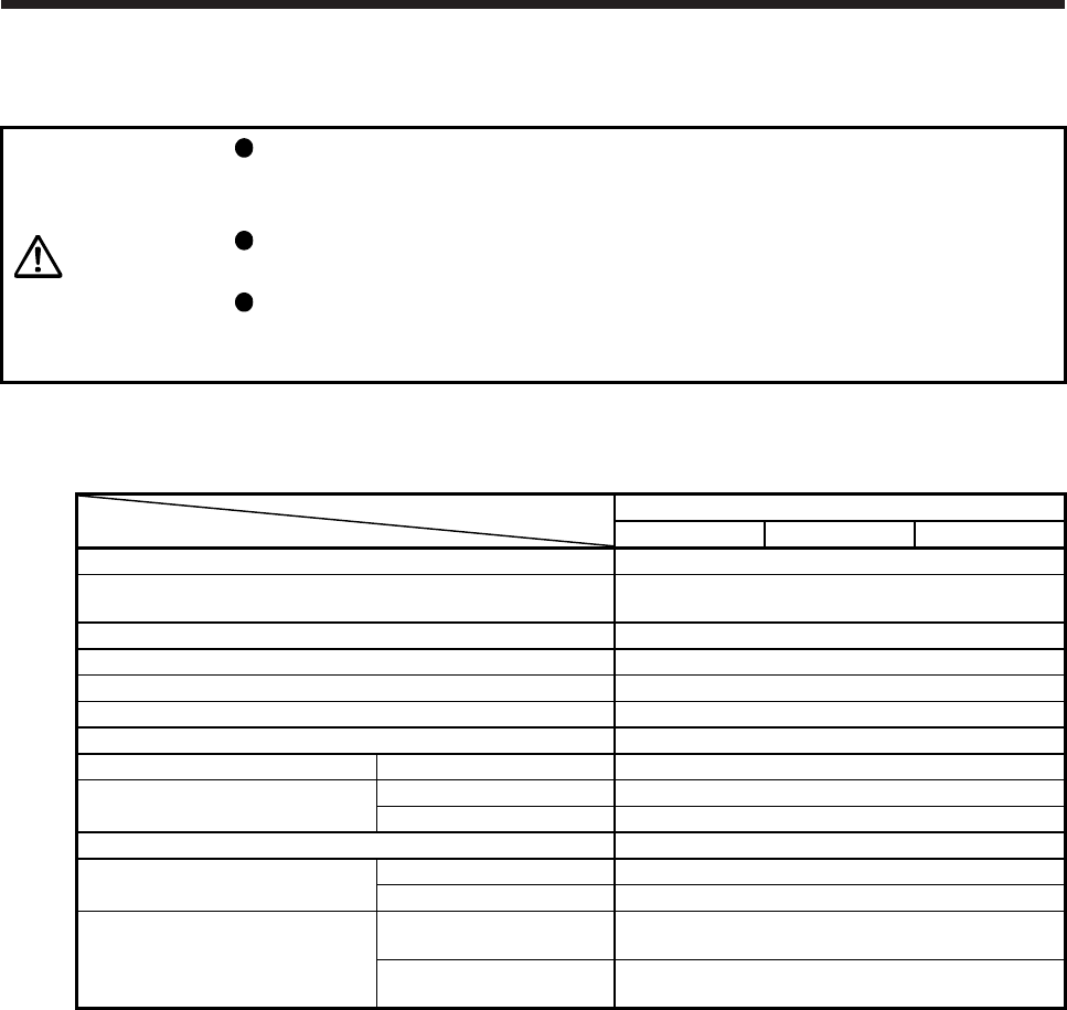
11. HG-AK SERIES
11 - 5
11.4 Electromagnetic brake characteristics
CAUTION
The electromagnetic brake is provided to prevent a drop at a power failure or
servo alarm occurrence during vertical drive or to hold a shaft at a stop. Do not
use it for normal braking (including braking at servo-lock).
Before operating the servo motor, be sure to confirm that the electromagnetic
brake operates properly.
The operation time of the electromagnetic brake varies depending on the power
supply circuit you use. Be sure to check the operation delay time with a real
machine.
The characteristics of the electromagnetic brake provided for the servo motor with an electromagnetic brake
are indicated below.
Servo motor
Item
HG-AK series
0136B 0236B 0336B
Type (Note 1) Spring-loaded safety brake
Rated voltage (Note 4) 24 V DC 0
-10%
Power consumption [W] at20 °C 1.8
Coil resistance (Note 6) [Ω] at20 °C 320
Inductance (Note 6) [H] 1.6
Brake static friction torque [N•m] 0.095
Release delay time (Note 2) [s] 0.03
Braking delay time (Note 2) [s] DC off 0.01
Permissible braking work Per braking [J] 4.6
Per hour [J] 46
Brake looseness at servo motor shaft (Note 5) [degree] 0.1 to 2.5
Brake life (Note 3) Number of brakings [times] 20000
Work per braking [J] 1
Selection example of surge
absorbers to be used (Note 7, 8)
For the suppressed voltage
125 V TND20V-680KB
For the suppressed voltage
350 V TND10V-221KB
Note 1. It does not have a manual release mechanism. Use a 24 V DC power supply to release the brake electrically.
2. The value for initial on gap at 20 °C.
3. The brake gap will increase as the brake lining wears, but the gap is not adjustable. The brake life is defined as the
number of brakings until adjustment will be required.
4.
A
lways prepare a power supply exclusively used for the electromagnetic brake.
5. These are design values. These are not guaranteed values.
6. These are measured values. These are not guaranteed values.
7. Select the electromagnetic brake control relay properly, considering the characteristics of the electromagnetic brake
and surge absorber. When you use a diode for a surge absorber, the electromagnetic braking time will be longer.
8. Manufactured by Nippon Chemi-Con Corporation.
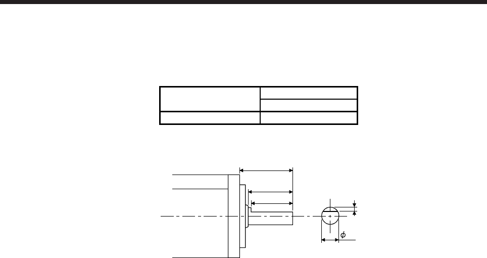
11. HG-AK SERIES
11 - 6
11.5 Servo motors with special shafts
The servo motors with special shafts indicated by the symbols (D) in the table are available. D is the symbol
attached to the servo motor model names.
Servo motor Shaft shape
D cut shaft
HG-AK_(B) D
[Unit: mm]
16
13
10
0.5
5h6

11. HG-AK SERIES
11 - 7
11.6 Dimensions
Moment of inertia on the table is the value calculated by converting the total value of moment of inertia for
servo motor and electromagnetic brake to servo motor shaft.
The dimensions without tolerances are general tolerance.
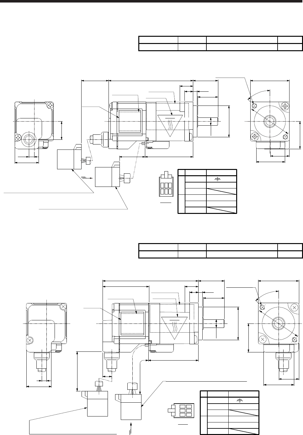
11. HG-AK SERIES
11 - 8
11.6.1 Standard (without an electromagnetic brake)
Model Output [W] Moment of inertia J [× 10-4 kg•m2] Mass [kg]
HG-AK0136 10 0.0029 0.12
[Unit: mm]
Encoder cable
Housing: J21DF-10V-KX-L
Terminal: SJ2F-002GF-P1.0 (Manufactured by JST)
Power cable
Housing: J21DF-06V-KX-L
Terminal: SJ2F-01GF-P1.0 (Manufactured by JST)
(Power lead 4-AWG24)
123 B
123 A
Power connector
16
13
54
5.4 2.5
φ20h7
30.7
200
225+20
0
+20
0 □25
φ28
17.5
12.3
18.6
15.4
11.5
3.4
Bottom
Top
Top
A
45°
2-M3 scre
w
mounting position
φ5h6
View A
Motor plate
(Opposite side)
Caution plate
Pin No.
1
3
1
2
3
2
A
B
Signal name
W
V
U
(E)
BC42526E
8 (Note 1)
(Note 2)
(Note 2)
Bottom
Top
Caution plate
(Opposite side)
TÜV label
Bottom
Note 1. The length of mounting screw should be within this.
2. The encoder cable outlet portion has been changed from the April 2013 production of the motors.
Model Output [W] Moment of inertia J [× 10-4 kg•m2] Mass [kg]
HG-AK0136-S100 10 0.0029 0.12
[Unit: mm]
Bottom
Top
Bottom
Top
Top
Power cable
Housing: J21DF-06V-KX-L
Terminal: SJ2F-01GF-P1.0 (Manufactured by JST)
A
225 +20
0
30.7
Encoder cable
Housing: J21DF-10V-KX-L
Terminal: SJ2F-002GF-P1.0 (Manufactured by JST)
1
2
3
BA
View A
12
3
15.4
3
□25
φ28
45°
2-M3 screw
mounting position
12.3
18.6
17.5
1658.7
28.5 8 (Note)
13
2.5
5.4
200 +20
0
5.6
φ20h7
φ5h6
Caution plate
(Opposite side)
Motor plate
(Opposite side)
Caution plate
TÜV label
Power connector
Pin No.
1
3
1
2
3
2
A
B
Signal name
W
V
U
(E)
BC43322A
Bottom
Note. The length of mounting screw should be within this.
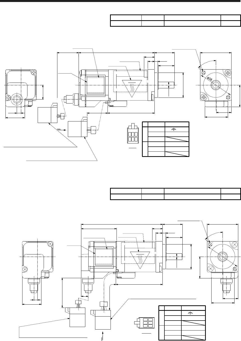
11. HG-AK SERIES
11 - 9
Model Output [W] Moment of inertia J [× 10-4 kg•m2] Mass [kg]
HG-AK0236 20 0.0045 0.14
[Unit: mm]
Encoder cable
Housing: J21DF-10V-KX-L
Terminal: SJ2F-002GF-P1.0 (Manufactured by JST)
Power cable
Housing: J21DF-06V-KX-L
Terminal: SJ2F-01GF-P1.0 (Manufactured by JST)
(Power lead 4-AWG24)
16
13
61
5.4 2.5
φ20h7
37.7
200+20
0
+20
0
225
□25
17.5
12.3
18.6
15.4
11.5
3.4
Top
A
45°
2-M3 screw
mounting position
φ5h6
Motor plate
(Opposite side)
Caution plate
8 (Note 1)
(Note 2)(Note 2)
123 B
123 A
Power connector
View A
Pin No.
1
3
1
2
3
2
A
B
Signal name
W
V
U
(E)
BC42527E
Bottom
Top
Caution plate
(Opposite side)
TÜV label Bottom
Top
Bottom
Note 1. The length of mounting screw should be within this.
2. The encoder cable outlet portion has been changed from the April 2013 production of the motors.
Model Output [W] Moment of inertia J [× 10-4 kg•m2] Mass [kg]
HG-AK0236-S100 20 0.0045 0.14
[Unit: mm]
16
13
5.4 2.5
φ20h7
37.7
8 (Note)
Top
φ5h6
View A
Motor plate
(Opposite side)
Caution plate
Encoder cable
Housing: J21DF-10V-KX-L
Terminal: SJ2F-002GF-P1.0 (Manufactured by JST)
Power cable
Housing: J21DF-06V-KX-L
Terminal: SJ2F-01GF-P1.0 (Manufactured by JST)
A
Bottom
Top
Caution plate
(Opposite side)
200 +20
0
225 +20
0
5.6
15.4
3
□25
φ28
45°
2-M3 screw
mounting position
12.3
18.6
17.5
28.5
65.7
TÜV label
Power connector
Pin No.
1
3
1
2
3
2
A
B
Signal name
W
V
U
(E)
1
2
3
BA
12
3
BC43323A
Bottom
Top
Bottom
Note. The length of mounting screw should be within this.
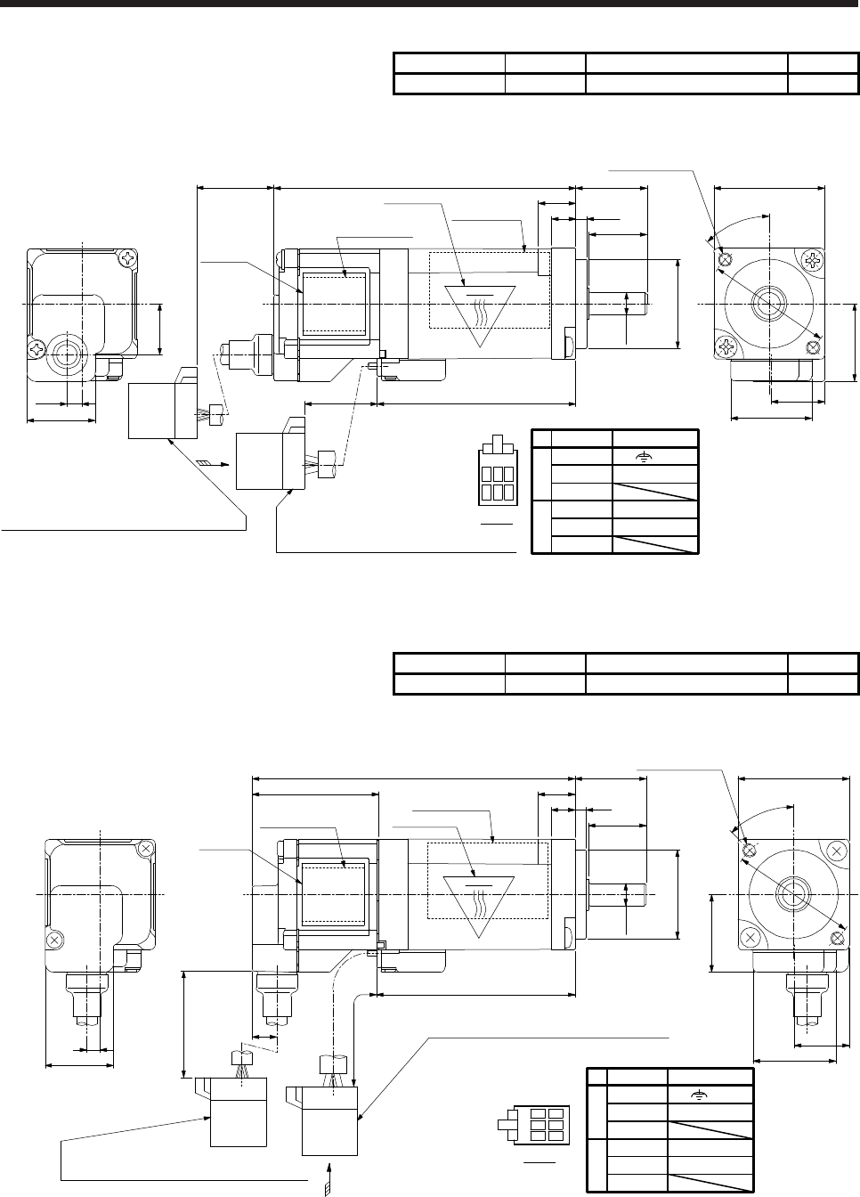
11. HG-AK SERIES
11 - 10
Model Output [W] Moment of inertia J [× 10-4 kg•m2] Mass [kg]
HG-AK0336 30 0.0061 0.16
[Unit: mm]
Encoder cable
Housing: J21DF-10V-KX-L
Terminal: SJ2F-002GF-P1.0(Manufactured by JST)
Power cable
Housing: J21DF-06V-KX-L
Terminal: SJ2F-01GF-P1.0(Manufactured by JST)
(Power lead 4-AWG24)
16
13
68
5.4 2.5
φ20h7
44.7
200+20
0
+20
0
225
□25
φ28
17.5
12.3
18.6
15.4
11.5
3.4
Bottom
Top
Bottom
Top
A
45°
2-M3 screw
mounting position
φ5h6
Motor plate
(Opposite side)
Caution plate
123 B
123 A
Power connector
View A
Pin No.
1
3
1
2
3
2
A
B
Signal name
W
V
U
(E)
BC42528E
8 (Note 1)
(Note 2)
(Note 2)
Bottom
Top
Caution plate
(Opposite side)
TÜV label
Note 1. The length of mounting screw should be within this.
2. The encoder cable outlet portion has been changed from the April 2013 production of the motors.
Model Output [W] Moment of inertia J [× 10-4 kg•m2] Mass [kg]
HG-AK0336-S100 30 0.0061 0.16
[Unit: mm]
Encoder cable
Housing: J21DF-10V-KX-L
Terminal: SJ2F-002GF-P1.0 (Manufactured by JST)
Power cable
Housing: J21DF-06V-KX-L
Terminal: SJ2F-01GF-P1.0 (Manufactured by JST)
16
13
72.7
28.5
5.4 2.5
φ20h7
44.7
□25
φ28
15.4
3
8 (Note)
Bottom
Top
Bottom
Top
A
45°
2-M3 screw
mounting position
φ5h6
View A
Motor plate
(Opposite side)
Caution plate
Bottom
Top
12.3
18.6
Caution plate
(Opposite side)
200 +20
0
225 +20
0
5.6
17.5
TÜV label
Power connector
Pin No.
1
3
1
2
3
2
A
B
Signal name
W
V
U
(E)
1
2
3
BA
12
3
BC43289A
Note. The length of mounting screw should be within this.
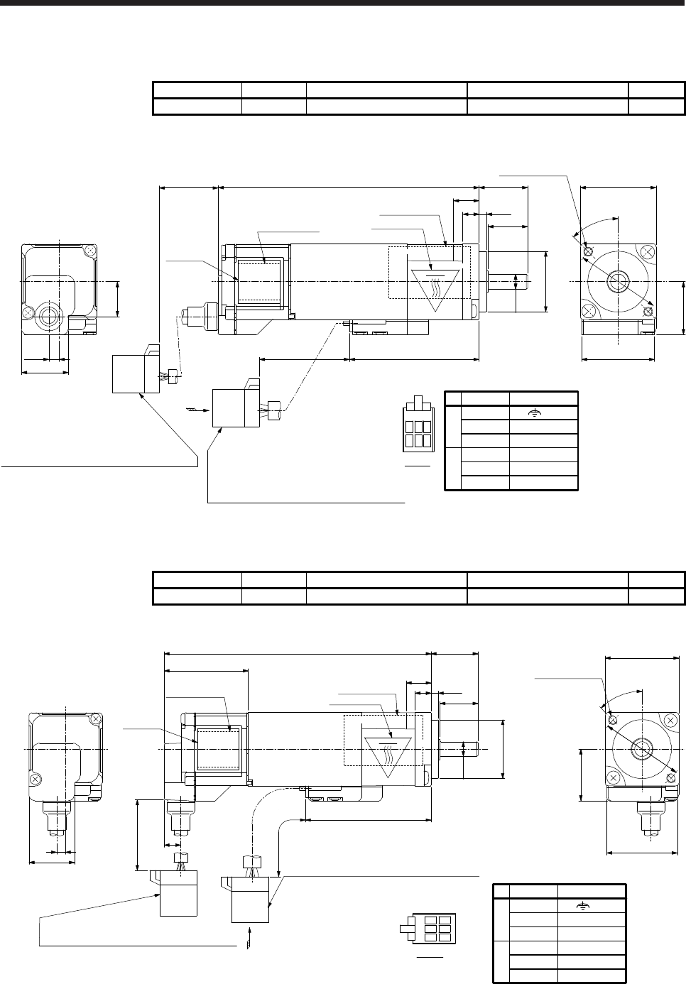
11. HG-AK SERIES
11 - 11
11.6.2 With an electromagnetic brake
Model Output [W] Brake static friction torque [N•m] Moment of inertia J [× 10-4 kg•m2] Mass [kg]
HG-AK0136B 10 0.095 0.0042 0.22
[Unit: mm]
Encoder cable
Housing: J21DF-10V-KX-L
Terminal: SJ2F-002GF-P1.0 (Manufactured by JST) Power cable
Housing: J21DF-06V-KX-L
Terminal: SJ2F-01GF-P1.0 (Manufactured by JST)
(Power lead 4-AWG24)
Terminal: SJ2F-002GF-P1.0 (Manufactured by JST)
(Brake lead 2-AWG26)
200+20
0
+20
0
245
□25
17.5
24
15.4
11.5
3.4
A
45°
2-M3 screw
mounting position
Motor plate
(Opposite side)
Caution plate
φ28
φ5h6
Top
Top
16
13
5.4 2.5
φ20h7
42.7
86
8 (Note 1)
(Note 2)
(Note 2)
123 B
123 A
Power connector
View A
Pin No.
1
3
1
2
3
2
A
B
Signal name
W
B1
B2
V
U
(E)
BC42542E
Bottom
Top
Caution plate
(Opposite side)
TÜV label Bottom
Bottom
Note 1. The length of mounting screw should be within this.
2. The encoder cable outlet portion has been changed from the April 2013 production of the motors.
Model Output [W] Brake static friction torque [N•m] Moment of inertia J [× 10-4 kg•m2] Mass [kg]
HG-AK0136B-S100 10 0.095 0.0042 0.22
[Unit: mm]
Encoder cable
Housing: J21DF-10V-KX-L
Terminal: SJ2F-002GF-P1.0 (Manufactured by JST)
Power cable
Housing: J21DF-06V-KX-L
Terminal: SJ2F-01GF-P1.0 (Manufactured by JST)
(Power lead 4-AWG24)
Terminal: SJ2F-002GF-P1.0 (Manufactured by JST)
(Brake lead 2-AWG26)
28.5
□25
17.5
24
2-M3 screw
mounting position
42.7
Bottom
Top
Caution plate
(Opposite side)
15.4
3
200 +20
0
5.6
A
245 +20
0
View A
φ28
45°
Top
Top
1690.7
8 (Note)
13
2.5
5.4
φ20h7
φ5h6
Motor plate
(Opposite side)
Caution plate
TÜV label
Power connector
Pin No.
1
3
1
2
3
2
A
B
Signal name
W
B1
B2
V
U
(E)
1
2
3
BA
12
3
BC43939*
Bottom
Bottom
Note. The length of mounting screw should be within this.
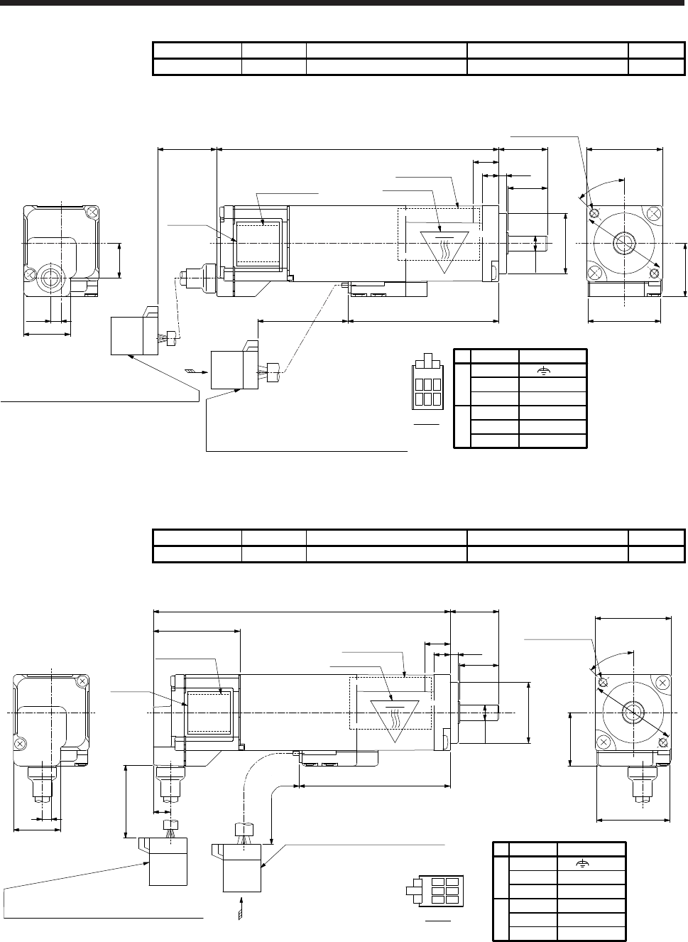
11. HG-AK SERIES
11 - 12
Model Output [W] Brake static friction torque [N•m] Moment of inertia J [× 10-4 kg•m2] Mass [kg]
HG-AK0236B 20 0.095 0.0058 0.24
[Unit: mm]
Encoder cable
Housing: J21DF-10V-KX-L
Terminal: SJ2F-002GF-P1.0 (Manufactured by JST) Power cable
Housing: J21DF-06V-KX-L
Terminal: SJ2F-01GF-P1.0 (Manufactured by JST)
(Power lead 4-AWG24)
Terminal: SJ2F-002GF-P1.0 (Manufactured by JST)
(Brake lead 2-AWG26)
200+20
0
+20
0
245
□25
17.5
24
15.4
11.5
3.4
A
45°
2-M3 screw
mounting position
Motor plate
(Opposite side)
Caution plate
φ28
φ5h6
Top
16
13
5.4 2.5
φ20h7
49.7
93
123 B
123 A
Power connector
View A
Pin No.
1
3
1
2
3
2
A
B
Signal name
W
B1
B2
V
U
(E)
BC42543E
8 (Note 1)
(Note 2)
(Note 2)
Bottom
Top
Caution plate
(Opposite side)
TÜV label
Top
Bottom
Bottom
Note 1. The length of mounting screw should be within this.
2. The encoder cable outlet portion has been changed from the April 2013 production of the motors.
Model Output [W] Brake static friction torque [N•m] Moment of inertia J [× 10-4 kg•m2] Mass [kg]
HG-AK0236B-S100 20 0.095 0.0058 0.24
[Unit: mm]
Encoder cable
Housing: J21DF-10V-KX-L
Terminal: SJ2F-002GF-P1.0 (Manufactured by JST)
Power cable
Housing: J21DF-06V-KX-L
Terminal: SJ2F-01GF-P1.0 (Manufactured by JST)
(Power lead 4-AWG24)
Terminal: SJ2F-002GF-P1.0 (Manufactured by JST)
(Brake lead 2-AWG26)
28.5
□25
17.5
24
2-M3 screw
mounting position
Bottom
Top
Caution plate
(Opposite side)
15.4
3
200 +20
0
5.6
A
245 +20
0
View A
φ28
45°
16
13
5.4 2.5
φ20h7
49.7
8 (Note)
Top
φ5h6
Motor plate
(Opposite side)
Caution plate
97.7
TÜV label
Power connector
Pin No.
1
3
1
2
3
2
A
B
Signal name
W
B1
B2
V
U
(E)
1
2
3
BA
12
3
BC43941*
Bottom
Top
Bottom
Note. The length of mounting screw should be within this.
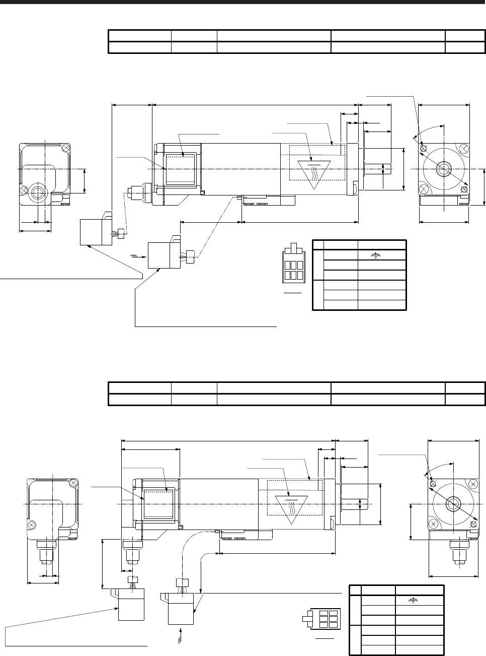
11. HG-AK SERIES
11 - 13
Model Output [W] Brake static friction torque [N•m] Moment of inertia J [× 10-4 kg•m2] Mass [kg]
HG-AK0336B 30 0.095 0.0074 0.26
[Unit: mm]
Encoder cable
Housing: J21DF-10V-KX-L
Terminal: SJ2F-002GF-P1.0 (Manufactured by JST)
Power cable
Housing: J21DF-06V-KX-L
Terminal: SJ2F-01GF-P1.0 (Manufactured by JST)
(Power lead 4-AWG24)
Terminal: SJ2F-002GF-P1.0 (Manufactured by JST)
(Brake lead 2-AWG26)
200+20
0
+20
0
245
□25
17.5
24
15.4
11.5
3.4
A
45°
2-M3 screw
mounting position
Motor plate
(Opposite side)
Caution plate
φ28
φ5h6
Top
Top
Bottom
Bottom
16
13
5.4 2.5
φ20h7
56.7
8 (Note 1)
100
123 B
123 A
Power connector
View A
Pin No.
1
3
1
2
3
2
A
B
Signal name
W
B1
B2
V
U
(E)
BC42544E
(Note 2)
(Note 2)
Bottom
Top
Caution plate
(Opposite side)
TÜV label
Note 1. The length of mounting screw should be within this.
2. The encoder cable outlet portion has been changed from the April 2013 production of the motors.
Model Output [W] Brake static friction torque [N•m] Moment of inertia J [× 10-4 kg•m2] Mass [kg]
HG-AK0336B-S100 30 0.095 0.0074 0.26
[Unit: mm]
Encoder cable
Housing: J21DF-10V-KX-L
Terminal: SJ2F-002GF-P1.0 (Manufactured by JST)
Power cable
Housing: J21DF-06V-KX-L
Terminal: SJ2F-01GF-P1.0 (Manufactured by JST)
(Power lead 4-AWG24)
Terminal: SJ2F-002GF-P1.0 (Manufactured by JST)
(Brake lead 2-AWG26)
28.5
□25
17.5
24
2-M3 screw
mounting position
Motor plate
(Opposite side)
Caution plate
φ28
Top
Top
Bottom
Bottom
16
13
5.4 2.5
φ20h7
φ5h6
56.7
8 (Note)
104.7
Bottom
Top
Caution plate
(Opposite side)
15.4
3
200 +20
0
5.6
A
245 +20
0
View A
45°
TÜV label
Power connector
Pin No.
1
3
1
2
3
2
A
B
Signal name
W
B1
B2
V
U
(E)
BC43293B
1
2
3
BA
12
3
Note. The length of mounting screw should be within this.

11. HG-AK SERIES
11 - 14
MEMO

APPENDIX
App. - 1
App. 1 Servo motor ID codes
Servo motor series ID Servo motor type ID Servo motor encoder ID Servo motor
F053 HG-MR053
FF13 HG-MR13
0101 FF23 HG-MR23
FF43 HG-MR43
FF73 HG-MR73
F053 HG-KR053
FF13 HG-KR13
0111 FF23 HG-KR23
FF43 HG-KR43
FF73 HG-KR73
0121
FF51 HG-SR51
FF81 HG-SR81
F121 HG-SR121
F201 HG-SR201
F301 HG-SR301
F421 HG-SR421
FF52 HG-SR52
F102 HG-SR102
F152 HG-SR152
F202 HG-SR202
F352 0044 HG-SR352
F502 HG-SR502
F702 HG-SR702
0122
FF52 HG-SR524
F102 HG-SR1024
F152 HG-SR1524
F202 HG-SR2024
F352 HG-SR3524
F502 HG-SR5024
F702 HG-SR7024
0131
FF53 HG-JR53
FF73 HG-JR73
F103 HG-JR103
F153 HG-JR153
F203 HG-JR203
F353 HG-JR353
F503 HG-JR503
F703 HG-JR703
F903 HG-JR903
F701 HG-JR701M
1101 HG-JR11K1M
1501 HG-JR15K1M
2201 HG-JR22K1M
3001 HG-JR30K1M
3701 HG-JR37K1M

APPENDIX
App. - 2
Servo motor series ID Servo motor type ID Servo motor encoder ID Servo motor
FF53 HG-JR534
FF73 HG-JR734
F103 HG-JR1034
F153 HG-JR1534
F203 HG-JR2034
F353 HG-JR3534
F503 HG-JR5034
F703 HG-JR7034
0132 F903 HG-JR9034
F701 HG-JR701M4
1101 HG-JR11K1M4
1501 HG-JR15K1M4
2201 HG-JR22K1M4
3001 HG-JR30K1M4
3701 HG-JR37K1M4
4501 HG-JR45K1M4
5501 HG-JR55K1M4
F601 HG-JR601
F801 HG-JR801
1201 HG-JR12K1
0133 1501 HG-JR15K1
2001 HG-JR20K1
2501
0044 HG-JR25K1
3001 HG-JR30K1
3701 HG-JR37K1
F601 HG-JR6014
F801 HG-JR8014
1201 HG-JR12K14
0134 1501 HG-JR15K14
2001 HG-JR20K14
2501 HG-JR25K14
3001 HG-JR30K14
3701 HG-JR37K14
F103 HG-RR103
F153 HG-RR153
0141 F203 HG-RR203
F353 HG-RR353
F503 HG-RR503
FF72 HG-UR72
F152 HG-UR152
0151 F202 HG-UR202
F352 HG-UR352
F502 HG-UR502
F013 HG-AK0136
0D F023 HG-AK0236
F033 HG-AK0336

APPENDIX
App. - 3
App. 2 Manufacturer list
Names given in the table are as of April 2015.
Manufacturer Contact
3M 3M
JST J.S.T. Mfg. Co., Ltd.
JX Nippon Oil & Energy JX Nippon Oil & Energy Corporation
Idemitsu Kosan Idemitsu Kosan Co., Ltd
Exxon Mobil Exxon Mobil Corporation
Cosmo Oil Cosmo Oil Co., Ltd.
Shell Oil Shell Oil Company
DDK DDK Ltd.
TE Connectivity TE Connectivity Ltd. Company
Taiyo Cabletec Taiyo Cabletec Corporation
Toa Electric Industrial Toa Electric Industrial Co., Ltd.
Nippon Chemi-Con Nippon Chemi-con Corporation
JAE Japan Aviation Electronics Industry, Limited
Harmonic Drive Systems Harmonic Drive Systems Inc.
Panasonic Panasonic Corporation
Hirose Electric Hirose Electric Co., Ltd.
Molex Molex

APPENDIX
App. - 4
App. 3 Compliance with the CE marking
App. 3.1 What is CE marking?
The CE marking is mandatory and must be affixed to specific products placed on the European Union. When
a product conforms to the requirements, the CE marking must be affixed to the product. The CE marking
also applies to machines and equipment incorporating servos.
(1) EMC directive
The EMC directive applies to the servo motor alone. Therefore servo motor is designed to comply with
the EMC directive. The EMC directive also applies to machines and equipment incorporating servo
motors.
(2) Low voltage directive
The low voltage directive also applies to the servo motor alone. The servo motor is designed to comply
with the low voltage directive.
(3) Machinery directive
The servo motor as a single unit does not comply with the Machinery directive due to correspondence
with "Partly completed machinery" of 2006/42/EC article2 (g). However, machines and equipment
incorporating servo motors will be complied. Please check your machines and equipment as a whole if
they are complied.
App. 3.2 For compliance
Be sure to perform an appearance inspection of every unit before installation. In addition, have a final
performance inspection on the entire machine/system, and keep the inspection record.
(1) Wiring
Use wirings which complies with EN for the servo motor power. Complying EN products are available as
options. Refer to chapter 5 for details of the options.
(2) Performing EMC tests
When EMC tests are run on a machine and device into which the servo motor and servo motor have
been installed, it must conform to the electromagnetic compatibility (immunity/emission) standards after
it has satisfied the operating environment and electrical equipment specifications.
For EMC directive conforming methods about servo amplifiers and servo motors, refer to the EMC
Installation Guidelines (IB(NA)67310) and each Servo Amplifier Instruction Manual.
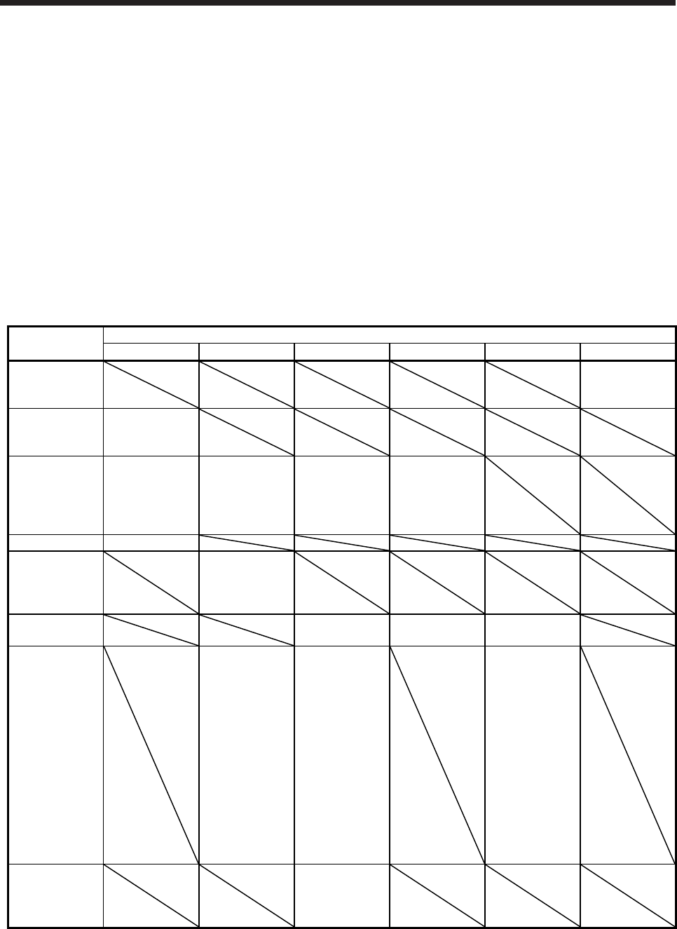
APPENDIX
App. - 5
App. 4 Compliance with UL/CSA standard
Use the UL/CSA standard-compliant model of servo motor. For the latest information of compliance, contact
your local sales office.
Unless otherwise specified, the handling, performance, specifications, etc. of the UL/CSA standard-
compliant models are the same as those of the standard models.
(1) Flange size
The servo motor is compliant with the UL/CSA standard when it is mounted on the flanges made of
aluminum whose sizes are indicated in the following table.
The rated torque of the servo motor under the UL/CSA standard indicates the continuous permissible
torque value that can be generated when it is mounted on the flange specified in this table and used in
the environment of 0 °C to 40 °C ambient temperature. Therefore, to conform to the UL/CSA standard,
mount the servo motor on a flange with a heat radiating effect equivalent to that of this flange.
Flange size
[mm]
Servo motor
HG-MR/HG-KR HG-SR HG-JR HG-RR HG-UR HG-AK
150 × 150 × 3
0136
0236
0336
250 × 250 × 6
053
13
23
250 × 250 × 12 43
51
81
52(4)
102(4)
152(4)
53(4)
73(4)
103(4)
153(4)
203(4)
103
153
203
300 × 300 × 12 73
300 × 300 × 20
121
201
202(4)
352(4)
550 × 550 × 30 353(4)
503(4)
353
503
72
152
650 × 650 × 35
301
421
502(4)
702(4)
703(4)
903(4)
701M(4)
11K1M(4)
15K1M(4)
22K1M(4)
30K1M(4)
37K1M(4)
601(4)
801(4)
12K1(4)
15K1(4)
20K1(4)
25K1(4)
202
352
502
950 × 950 × 35
45K1M4
55K1M4
30K1(4)
37K1(4)
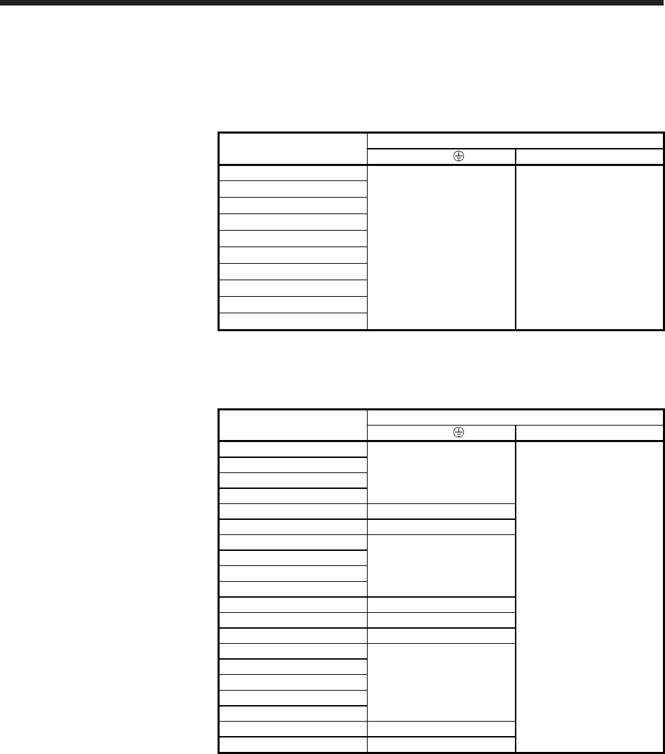
APPENDIX
App. - 6
(2) Selection example of wires
To comply with the UL/CSA standard, use UL-approved copper wires rated at 75 °C for wiring.
The following table shows wires [AWG] rated at 75 °C.
(a) HG-MR series and HG-KR series
Servo motor Wire [AWG]
U/V/W/ B1/B2
HG-MR053
14 (Note) 16 (Note)
HG-MR13
HG-MR23
HG-MR43
HG-MR73
HG-KR053
HG-KR13
HG-KR23
HG-KR43
HG-KR73
Note. For fabricating extension cables to wire a servo amplifier and a servo motor, use the
option. Refer to chapter 5 for details of the options.
(b) HG-SR series
Servo motor Wire [AWG]
U/V/W/ B1/B2
HG-SR51
14
16
HG-SR81
HG-SR121
HG-SR201
HG-SR301 12
HG-SR421 10 (Note)
HG-SR52
14
HG-SR102
HG-SR152
HG-SR202
HG-SR352 12
HG-SR502 10 (Note)
HG-SR702 8 (Note)
HG-SR524
14
HG-SR1024
HG-SR1524
HG-SR2024
HG-SR3524
HG-SR5024 12 (Note)
HG-SR7024 10 (Note)
Note. Refer to each servo amplifier instruction manual for crimp terminals and crimping
tools used for connection with the servo amplifier.
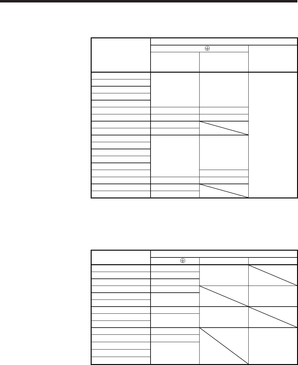
APPENDIX
App. - 7
(c) HG-JR series
1) 3000 r/min series
Servo motor
Wire [AWG]
U/V/W/
B1/B2
Standard
When the maximum
torque is 400%
(Note 2)
HG-JR53
HG-JR73
HG-JR103 14 14
HG-JR153
HG-JR203
HG-JR353 12 12 (Note 1)
HG-JR503 10 (Note 1) 10 (Note 1)
HG-JR703 8 (Note 1)
HG-JR903 6 (Note 1) 16
HG-JR534
HG-JR734
HG-JR1034 14 14
HG-JR1534
HG-JR2034
HG-JR3534 14 (Note 1)
HG-JR5034 12 (Note 1) 12 (Note 1)
HG-JR7034 10 (Note 1)
HG-JR9034 8 (Note 1)
Note 1. Refer to each servo amplifier instruction manual for crimp terminals and crimping
tools used for connection with the servo amplifier.
2. The maximum torque can be increased to 400% by changing the servo amplifier.
Refer to section 8.2 for the combinations.
2) 1500 r/min series
Servo motor Wire [AWG]
U/V/W/ B1/B2 BU/BV/BW
HG-JR701M 8 (Note)
HG-JR11K1M 6 (Note) 16
HG-JR15K1M 4 (Note)
HG-JR22K1M 2 (Note)
HG-JR30K1M 2/0 (Note) 16
HG-JR37K1M
HG-JR701M4 12 (Note)
HG-JR11K1M4 8 (Note) 16
HG-JR15K1M4
HG-JR22K1M4 6 (Note)
HG-JR30K1M4 4 (Note)
HG-JR37K1M4 16
HG-JR45K1M4 2 (Note)
HG-JR55K1M4
Note. Refer to each servo amplifier instruction manual for crimp terminals and crimping tools
used for connection with the servo amplifier.
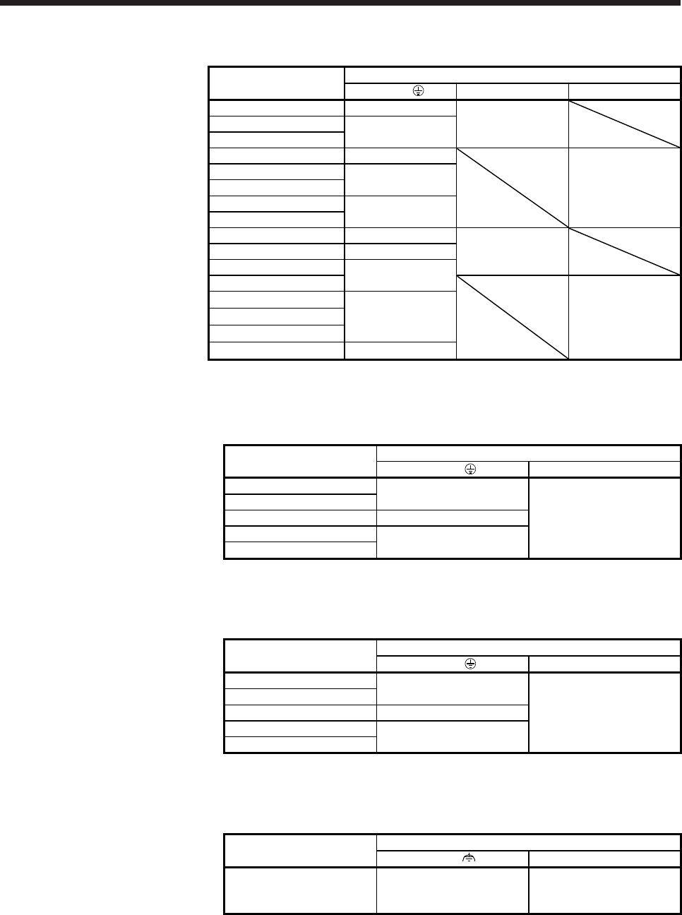
APPENDIX
App. - 8
3) 1000 r/min series
Servo motor Wire [AWG]
U/V/W/ B1/B2 BU/BV/BW
HG-JR601 8 (Note)
HG-JR801 6 (Note) 16
HG-JR12K1
HG-JR15K1 4 (Note)
HG-JR20K1 2 (Note)
HG-JR25K1 16
HG-JR30K1 2/0 (Note)
HG-JR37K1
HG-JR6014 12 (Note)
HG-JR8014 10 (Note) 16
HG-JR12K14 8 (Note)
HG-JR15K14
HG-JR20K14
HG-JR25K14 6 (Note) 16
HG-JR30K14
HG-JR37K14 4 (Note)
Note. Refer to each servo amplifier instruction manual for crimp terminals and crimping tools
used for connection with the servo amplifier.
(d) HG-RR series
Servo motor Wire [AWG]
U/V/W/ B1/B2
HG-RR103 14
16
HG-RR153
HG-RR203 12
HG-RR353 10 (Note)
HG-RR503
Note. Refer to each servo amplifier instruction manual for crimp terminals and crimping
tools used for connection with the servo amplifier.
(e) HG-UR series
Servo motor Wire [AWG]
U/V/W/ B1/B2
HG-UR72 14
16
HG-UR152
HG-UR202 12
HG-UR352 10 (Note)
HG-UR502
Note. Refer to each servo amplifier instruction manual for crimp terminals and crimping
tools used for connection with the servo amplifier.
(f) HG-AK series
Servo motor Wire [AWG]
U/V/W B1/B2
HG-AK0136
HG-AK0236
HG-AK0336
14 (Note) 16
Note. This is applicable when fabricating an extension cable. Use an option for wiring with
the servo motor. Refer to chapter 5 for details of the options.

APPENDIX
App. - 9
App. 5 Calculation methods for designing
5.1 Specification symbol list
The following symbols are required for selecting the proper servo.
Ta: Acceleration torque [N•m] g: Gravitational acceleration (9.8 [m/s2])
Td: Deceleration torque [N•m] µ: Friction coefficient
TMa: Torque necessary for acceleration [N•m] π: Pi constant (3.14)
TMd: Torque necessary for deceleration [N•m] Pf: Number of feedback pulses in position control mode [pulse/rev]
TLH: Load torque converted into equivalent value
on servo motor shaft during stop
[N•m] f: Input pulse frequency in position control mode [pulse/s]
[N•m] f0: Input pulse frequency during fast feed in position control
mode
[pulse/s]
TL: Load torque converted into equivalent value
on servo motor shaft
[N•m] tpsa: Acceleration time constant of pulse frequency
command in position control mode
[s]
TU: Unbalanced torque [N•m] tpsd: Deceleration time constant of pulse frequency
command in position control mode
[s]
TF: Load friction torque [N•m]
TB: Brake static friction torque [N•m] Kp: Position loop gain 1 [rad/s]
TL0: Load torque on load shaft [N•m] Tp: Position control time constant (Tp = 1/Kp) [s]
Trms: Continuous effective load torque converted
into equivalent value on servo motor shaft
[N•m] ∆l: Feed per feedback pulses in position control mode
Travel distance per pulse
[mm/pulse]
JL: Load inertia moment converted into
equivalent value on servo motor shaft
[× 10-4 kg•m2]∆l0: Feed per command pulse in position control mode
Travel distance per command pulse
[mm/pulse]
JL0: Load inertia moment on load shaft [× 10-4 kg•m2] l: Feed [mm]
JM: Servo motor's rotor inertia moment [× 10-4 kg•m2] P: Number of internal command pulses [pulse]
N: Servo motor speed [r/min] ts: Internal settling time [s]
N0: Servo motor speed during fast feed [r/min] t0: Positioning time [s]
NL0: Load shaft speed during fast feed [r/min] tc: Time at constant speed of servo motor in one cycle [s]
V: Moving part speed [mm/min] tl: Stopping time in one cycle [s]
V0: Moving part speed during fast feed [mm/min] ∆ε: Positioning accuracy [mm]
PB: Ball screw lead [mm] ε: Number of droop pulses [pulse]
Z1: Number of gear teeth on servo motor shaft ∆S: Travel distance per servo motor revolution [mm/rev]
Z2: Number of gear teeth on load gear W: Mass [kg]
n: Gear ratio n = Z1
Z2 Lmax: Maximum coasting distance [mm]
Speed reduced when n > 1, Speed increased when n < 1
η: Drive system efficiency
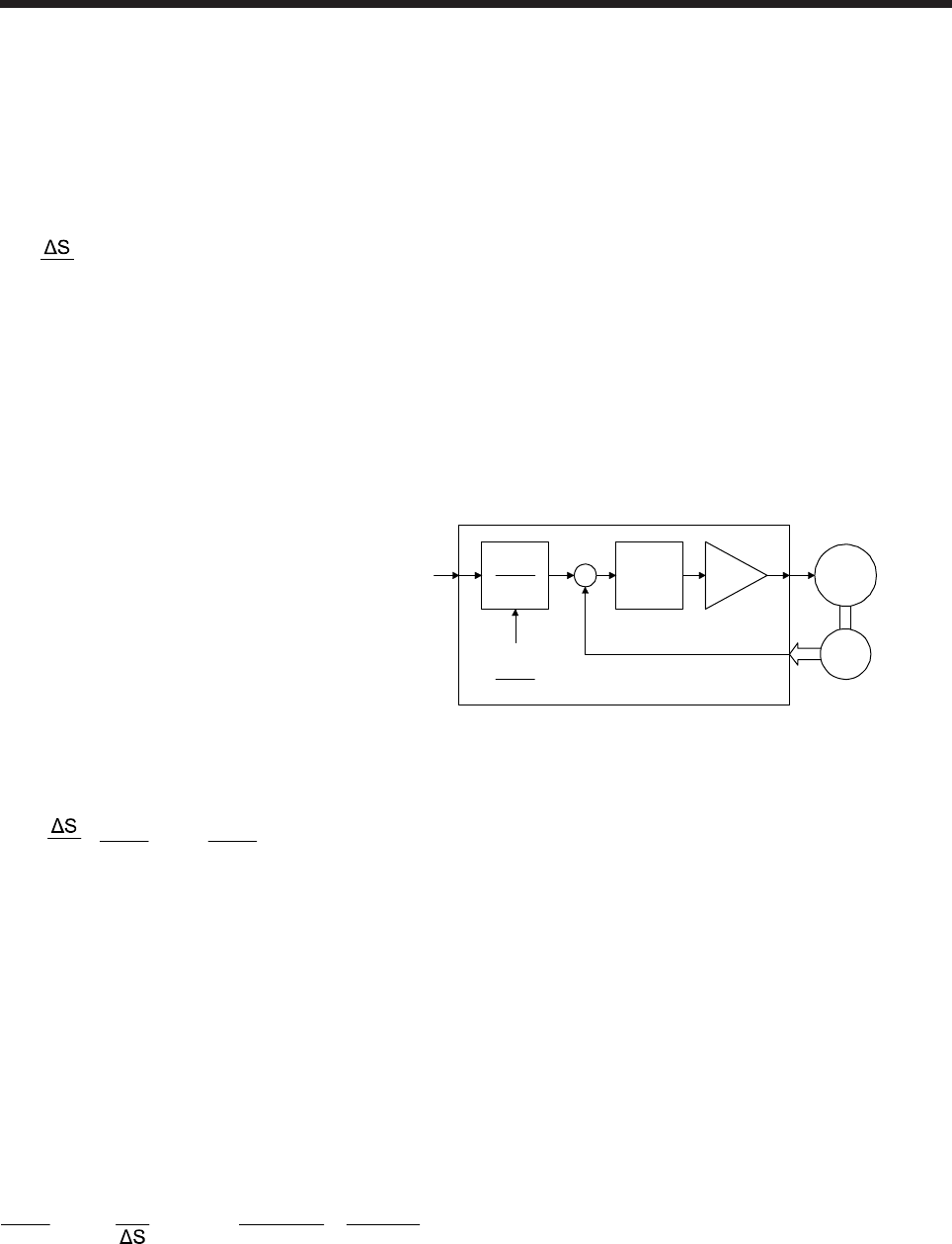
APPENDIX
App. - 10
App. 5.2 Position resolution and electronic gear setting
Position resolution (travel distance per pulse ∆l) is determined by travel distance per servo motor revolution
∆S and the number of encoder feedback pulses Pf, and is represented by Equation 5.1. As the number of
feedback pulses depends on the servo motor series, refer to standard specifications in the chapter of servo
motor series.
∆l = Pf
··························································································································· (5.1)
∆l: Travel distance per pulse [mm/pulse]
∆S: Travel distance per servo motor revolution [mm/rev]
Pf: Number of feedback pulses [pulse/rev]
Since ∆l has the relation represented by equation 5.1, its value is fixed in the control system after the drive
system and encoder have been determined. However, travel distance per command pulse can be set as
desired using the parameters.
Command pulse
frequency f0
+
-
Electronic gear
CMX
CDV
CMX
CDV
Deviation
counter
Encoder
M
Pf = 4194304 pulses/rev
Servo moto
r
As shown above, command pulses are multiplied by CMX/CDV set in the parameters to be position control
pulses. Travel distance per command pulse ∆l0 is expressed by Equation 5.2.
∆l0 = Pf
• CDV
CMX = ∆l • CDV
CMX ······························································································· (5.2)
CMX : Electronic gear (command pulse multiplication numerator)
CDV : Electronic gear (command pulse multiplication denominator)
Using the above relation, travel distance per command pulse can be set to a value without fraction.
[Setting example]
Find a parameter value for ∆l0 = 0.001 mm/pulse in a drive system where ball screw lead PB = 10 mm and
reduction ratio 1/n = 1.
The encoder feedback pulses Pf of the HG-KR = 4194304 pulses/rev.
Since ∆S = 10 mm/rev, the following is obtained according to equation 5.2.
CDV
CMX = ∆l0 • Pf = 0.001 • 10
4194304 = 625
262144
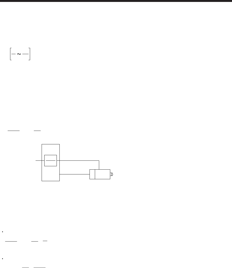
APPENDIX
App. - 11
Relation between position resolution ∆l and overall accuracy
Positioning accuracy of machine is the sum of electrical errors and mechanical errors. Normally, provisions
should be made so that positioning accuracy are not affected by electrical system errors. As a guideline,
Equation 5.3 should be satisfied.
∆l < 5
1
10
1 • ∆ε ············································································································· (5.3)
∆l: Travel distance per feedback pulse [mm/pulse]
∆ε: Positioning accuracy [mm]
App. 5.3 Speed and command pulse frequency
The servo motor is run at a speed where the command pulses and feedback pulses are equivalent.
Therefore, the command pulse frequency and feedback pulse frequency are equivalent. The following shows
the relation including the parameter settings (CMX and CDV). (Refer to the following diagram.)
f0 • CDV
CMX = Pf • 60
N0 ············································································································ (5.4)
Feedback pulse
frequency
f0
Electronic
gear
Servo motor
CMX
CDV
f0: Command pulse frequency [pulse/s]
(differential line driver)
CMX: Electronic gear
(command pulse multiplication numerator)
CDV: Electronic gear
(command pulse multiplication denominator)
N0: Servo motor speed [r/min]
Pf: Number of feedback pulses [pulse/rev]
(Pf = 4194304 for HG-KR)
According to equation 5.4, the following equations may be used to obtain the electronic gear and command
pulse frequency to rotate the servo motor at N0.
Electronic gear
CDV
CMX = Pf • 60
N0 • f0
1 ········································································································ (5.5)
Command pulse frequency
f0 = Pf • 60
N0 • CMX
CDV ········································································································· (5.6)

APPENDIX
App. - 12
[Setting example]
Obtain the command pulse frequency required to run the HG-KR at 3000 r/min.
The following result will be found according to equation 5.6.
f0 = 4194304 • 60
N0 • CMX
CDV
(Command pulse frequency)
= 4194304 • 60
3000 • 1
= 209715200 [pulses/s]
However, as the maximum input command pulse frequency in the differential line driver type is 4 Mpulses/s
for MR-J4 servo amplifier, 209715200 pulses/s cannot be entered.
To run the servo motor at the speed of 3000 r/min at not more than 4 Mpulses/s, the electronic gear setting
must be changed. This electronic gear is found by equation 5.5.
CDV
CMX = 4194304 • 60
3000 • 4 • 106
1
(Electronic gear)
=
625
32768
Therefore, the parameters are set to CMX = 32768 and CDV = 625.
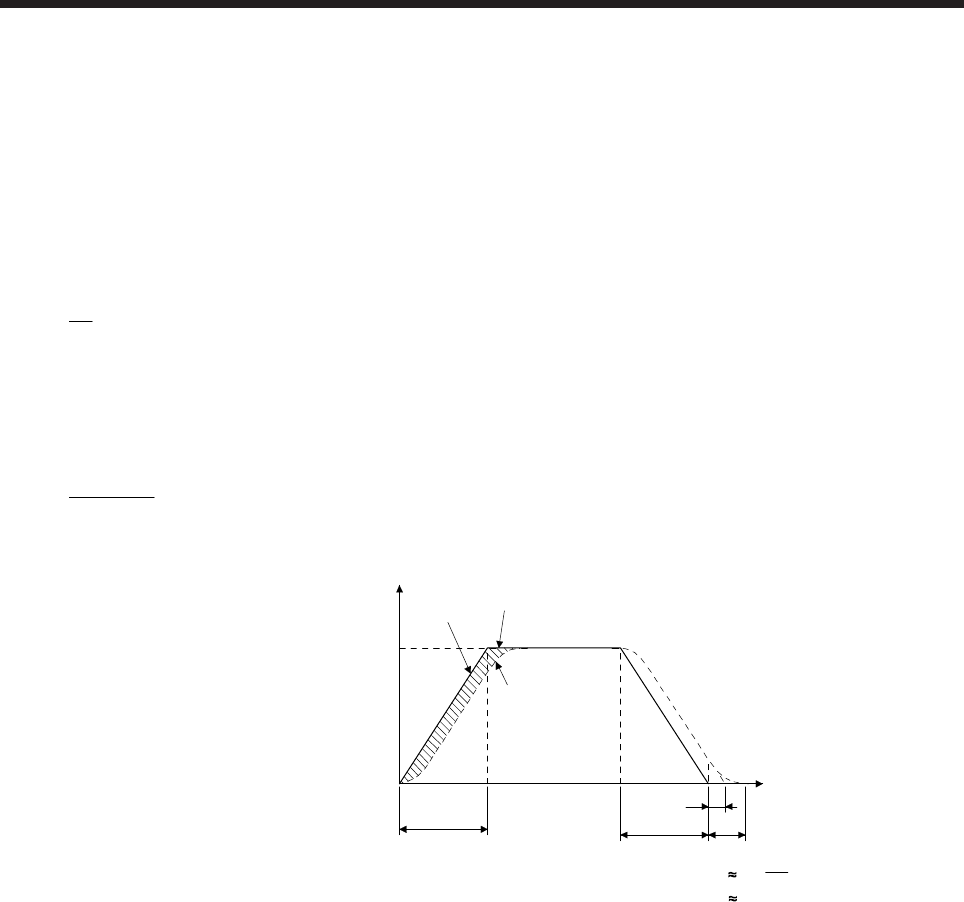
APPENDIX
App. - 13
5.4 Stopping characteristics
(1) Droop pulses (ε)
When you use a pulse train command to run the servo motor, the relation between the command pulse
frequency and servo motor speed will be as follows. The difference between the command pulses and
feedback pulses during acceleration are called droop pulses, which are accumulated in the servo
amplifier deviation counter. Equation 5.7 defines a relation between the command pulse frequency (f)
and position control gain 1 (Kp).
ε ≈ Kp
f0 [pulse] ·············································································································· (5.7)
Supposing that the value of position control gain 1 is 70 rad/s, the droop pulses during operation will be
as follows at the command pulse frequency of 200 kpulses/s according to equation 5.7.
ε ≈ 70
200 • 103
≈ 2858 [pulses]
ts
0.04
Tp
ts
tpsd
tpsa
0
Servo motor
speed
Droop pulses
Command
Time
1
70
Command pulse frequency f [pulse/s]
Servo motor speed [r/min]
3 •

APPENDIX
App. - 14
(2) Settling time (ts) during linear acceleration/deceleration
Since droop pulses still exist regardless of zero command pulse, settling time (ts) is required until the
servo motor stops.
Set the operation pattern in consideration for the settling time.
The settling time (ts) value is obtained according to equation 5.8.
ts ≈ 3 • Tp
= 3 • Kp
1 [s] ··············································································································· (5.8)
*When Kp = 70 [rad/s], ts ≈ 0.04 [s]. (above diagram)
The settling time (ts) indicates the time required for the servo motor to stop in the necessary positioning
accuracy range. This does not always mean that the servo motor has stopped completely. Thus,
especially when the servo motor is used in high-duty operation and positioning accuracy has no margin
for travel distance per pulse (∆l), the value obtained by equation 5.8 must be increased.
The settling time (ts) will vary with the moving part conditions. Especially when the load friction torque is
large, movement may be unstable near the stopping position.

APPENDIX
App. - 15
App. 5.5 Capacity selection
As a first step, confirm the load conditions and temporarily select the servo motor capacity.
Then, determine the operation pattern, calculate required torques according to the following equations, and
check that the servo motor of the initially selected capacity may be used for operation .
(1) Initial selection of servo motor capacity
After calculating the load torque (TL) and load moment of inertia (JL), select a servo motor which will
satisfy the following two relations.
Servo motor rated torque > TL
Servo motor JM > JL/m
m = 3 : High duty (more than 100 times/min.)
Settling time; 40 ms or less
m = 5 : Middle frequency (60 times/min. to 100 times/min.)
Settling time; 100 ms or less
m = Permissible load moment of inertia : Low duty (less than 60 times/min.)
Settling time; more than 100 ms
Find the acceleration and deceleration torques and continuous effective load torque as described in (2)
to make a final selection. For high-duty positioning, the load moment of inertia (JL) value should be as
small as possible.
If positioning is infrequent as in line control, the load moment of inertia (JL) value may be slightly larger
than in the above conditions.
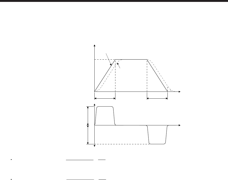
APPENDIX
App. - 16
(2) Acceleration and deceleration torques
The following equations are used to calculate the acceleration and deceleration torques in the following
operation pattern.
tpsd
tpsa
0
Servo motor
speed
Command
Time
Command pulse frequency f [pulse/s]
Servo motor speed [r/min]
N0f0
0
Ta
Td
Time
Acceleration
torque
Deceleration
torque
Acceleration torque Ta = (JL + JM)• N
0
9.55 • 104 • tpsa
1 ··································································· (5.9)
Deceleration torque Td = (JL + JM)• N
0
9.55 • 104 • tpsd
1 ··································································· (5.10)
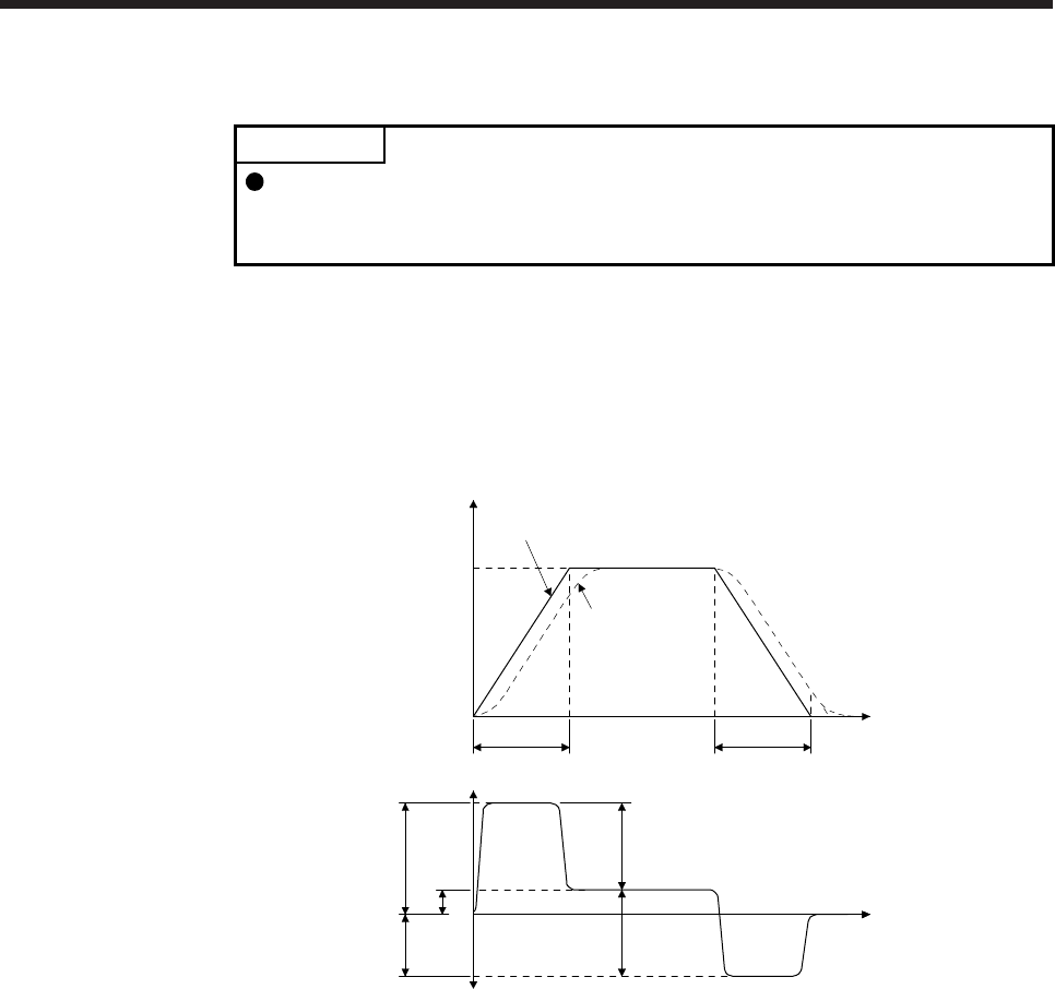
APPENDIX
App. - 17
(3) Torques required for operation
POINT
For the gain adjustment, check that the machine operates below the maximum
torque of the servo motor. It is recommended that generated torque during
operation is under 90% of the maximum torque of the servo motor.
Torques required for the servo motor are the highest during acceleration. If the servo motor torque found
with equation 5.11 to 5.13 exceed the maximum torque, the motor will not accelerate as commands. Set
the calculated value within the servo motor's maximum torque. Since a friction load is normally applied
during deceleration, only the acceleration torque needs to be considered. In the regenerative mode, the
value found by equation 5.13 is negative.
tpsd
tpsa
0
Servo motor
speed
Command
Time
Command pulse frequency f [pulse/s]
Servo motor speed [r/min]
N0f0
0
TL
TMd
TMa
Time
Servo motor torque
Ta
Td
T1
T2
T1 = TMa = Ta + TL ········································································································· (5.11)
T2 = TL ······················································································································· (5.12)
T3 = TMd = -Td + TL ········································································································ (5.13)
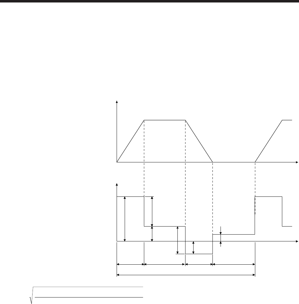
APPENDIX
App. - 18
(4) Continuous effective load torque
If the torque required for the servo motor changes with time, the continuous effective load torque should
be lower than the rated torque of the servo motor. There may be a servo motor torque delay at the start
of acceleration or deceleration due to a delay in the control system. To simplify the calculation, however,
it is assumed that constant acceleration and deceleration torques are applied during tpsa and tpsd.
The following equation is used to calculate the continuous effective load torque in the following operation
pattern. TLH indicates the torque applied during a servo motor stop. A large torque may be applied
especially during a stop in vertical motion applications, and this must be fully taken into consideration.
During vertical drive, the unbalanced torque TU will become TLH.
0
Servo motor speed N [r/min]
tpsd
Time
Time
TL
Ta
TdTMd
tpsa tc
tf (1 cycle)
tl
0
TMa
TLH
Servo motor torque
Trms = tf
TMa
2• tpsa + TL
2• tc+ TMd
2• tpsd + TLH
2• tl ································································· (5.14)
APPENDIX
App. - 19
App. 5.6 Load torque equations
Typical load torque equations are indicated below.
Type Mechanism Equation
Linear
movement
Servo moto
r
FC
Z2
Z1
FG
W
TL = F
2 • 103• • N
V = SF•
2 • 103• ····································· (5.15)
F: Force in the axial direction of the machine in linear motion [N]
F in equation 5.15 is obtained with equation 5.16 when the table is moved,
for example, as shown in the left diagram.
F = Fc + µ • (W • g + FG) ···························································· (5.16)
Fc: Force applied in the axial direction of the moving part [N]
FG: Tightening force of the table guide surface [N]
W: Full mass of the moving part [kg]
Rotary
movement
Servo motor
Z
1Z2
TL0
TL = n
1 • 1 • TL0 + TF ·································································· (5.17)
TF: Load friction torque converted into equivalent value on servo motor
shaft [N•m]
Vertical
movement
Servo motor
Counterweight
1/n
Guide
Load
W2
W1
During rise
TL = TU + TF ·········································································· (5.18)
During fall
TL = -TU • η2 + TF ···································································· (5.19)
TF: Friction torque of the moving part [N•m]
TU = (W1- W2)• g
2 • 103• • N
V = 2 • 103•
S(W1- W2)• g• ····························· (5.20)
TF = 2 • 103•
S(W1- W2)• g• ························································· (5.21)
W1: Mass of load [kg]
W2: Mass of counterweight [kg]
APPENDIX
App. - 20
App. 5.7 Load moment of inertia equations
Typical load moment of inertia equations is indicated below.
Type Mechanism Equation
Cylinder
Axis of rotation is on the cylinder
center
A
xis of rotation
L
D1
D2
JL0 = 32
• L • (D1- D2)
44
= 8
W • (D1+ D2)
22
······································ (5.22)
ρ: Cylinder material density [kg/cm3]
L: Cylinder length [cm]
D1: Cylinder outside diameter [cm]
D2: Cylinder inside diameter [cm]
W: Cylinder mass [kg]
Reference data: material density
Iron: 7.8 • 10-3 [kg/cm3]
Aluminum: 2.7 • 10-3 [kg/cm3]
Copper: 8.96 • 10-3 [kg/cm3]
Axis of rotation is on the cylinder
center
Axis of rotation D
R
JL0 = 8
W • (D2 + 8R2) ·································································· (5.23)
Square block
A
xis of rotation
R
a
abb
JL0 = W • 3
a2+ b2
+ R2 ····························································· (5.24)
W: Square block mass [kg]
a, b, R: Left diagram [cm]
Object which
moves linearly
Servo motor V
W
N
JL = W • V2
600 • = W • • N •
2•
1
10
V2
= W • S2
20 • ··········· (5.25)
V: Speed of object which moves linearly [mm/min]
∆S: Travel distance of object moving linearly per servo motor revolution
[mm/rev]
W: Square block mass [kg]
Object that is
hung with pulley
Servo motor
W
D
JL = W •
2
2
D + JP ····································································· (5.26)
JP: Pulley moment of inertia [× 10-4 kg•m2]
D: Pulley diameter [cm]
W: Square block mass [kg]
Converted
load
Load A
JA
J31
N3
J21
J11
J22 N2
N1
Load B
JB
JL = J11 + (J21 + J22 + JA) •
2
N1
N2 + (J31 + JB) •
2
N1
N3 ························ (5.27)
JA, JB: Moment of inertia of load A, B [× 10-4 kg•m2]
J11 to J31: Moment of inertia [× 10-4 kg•m2]
N1 to N3: Speed of each shaft [r/min]
APPENDIX
App. - 21
App. 5.8 Precautions for home position return
When a general positioning unit is used, the sequence of events is as shown in the following figure.
Proximity dog on starts deceleration
Creep speed V2
Home position return speed V1
Proximity dog
On Off
Zero pulse signal
When determining the on duration of the proximity dog,
consider the deceleration time so that the speed reaches
the creep speed.
Considering the variations of the proximity dog
operation, adjust the proximity dog so that it
switches off at the middle during the the zero
pulse signal on.
(1) When determining the on duration of the proximity dog, consider the delay time of the control section
and the deceleration time so that the creep speed is attained. If the proximity dog signal switches off
during deceleration, precise home position return cannot be performed.
Home position
return speed V1
Control delay
time t1
Deceleration
time td
On duration of the
proximity dog LD
Creep speed V2
Travel distance until reaching the
creep speed after proximity dog is
detected L1
Travel distance L1 in the chart can be obtained by equation 5.28.
L1 = 60
1 • V1 • t1 • + 120
1 • V1 • td • V1
1 -
2
V2 + 60
1 • V1 • TP ················································· (5.28)
On duration of the proximity dog LD [mm] must be longer than L1 obtained by equation 5.28, as indicated
in equation 5.29.
LD > L1 ······················································································································· (5.29)
where,
V1, V2: As shown in the chart [mm/min]
t1, td: As shown in the chart [s]
L1: As shown in the chart [mm]
LD: As shown in the chart [mm]
(2) Set the end (off position) of the proximity dog signal at the middle of two on positions (lows) of the zero
pulse signal. If it is set near either on position of the zero pulse signal, the positioning unit is liable to
misdetect the zero pulse signal. In this case, a fault will occur, e.g. the home position will shift by one
revolution of the servo motor.
APPENDIX
App. - 22
App. 5.9 Selection example
Servo motor
Machine
specification
Gear ratio 5: 8
Servo amplifier
Feed speed of moving part
Travel distance per command pulse
Feed per cycle
Positioning time
Number of feeds
Operation cycle
Reduction ratio
Moving part mass
Drive system efficiency
Friction coefficient
Ball screw lead
Ball screw diameter
Ball screw length
Gear diameter (servo motor shaft)
Gear diameter (load shaft)
Gear face width
Number of feedback pulses
V0 = 30000 [mm/min]
∆l0 = 0.001 [mm/pulse]
l = 400 [mm]
t0 = within 1 [s]
40 [times/min]
tf = 1.5 [s]
1/n = 5/8
W = 60 [kg]
η = 0.8
µ = 0.2
PB = 16 [mm]
DB = 20 [mm]
LB = 500 [mm]
DG1 = 25 [mm]
DG2 = 40 [mm]
LG = 10 [mm]
Pf = 4194304 [pulses/rev]
(1) Selection of control parameters
Setting of electronic gear (command pulse multiplication numerator/denominator)
There is the following relation between the electronic gear and command resolution ∆l0.
∆l0 = PB
Pf • n • CDV
CMX
When the above machining specifications are substituted in the above equation
0.001 = 4194304 • 8/5
16 • CDV
CMX
CDV
CMX = 1
1000 • 4194304 • 8/5
16 = 262144
625
CDV
CMX Acceptable as CMX/CDV is within 1/10 to 4000
(2) Servo motor speed
N0 = PB
V0 • 1/n
1 = 30000
16 • 5
8 = 3000 [r/min]
APPENDIX
App. - 23
(3) Acceleration/deceleration time constant
tpsa = tpsd = t0 - V0/60
l - ts = 0.05 [s]
ts: Settling time (Here, this is assumed to be 0.15 s.)
(4) Operation pattern
0.050.05
0Time [s]
3000
tpsa tpsd
t0 = 1.0
1 cycle tf = 1.5
ts
0.15
Servo motor speed [r/min]
(5) Load torque (converted into equivalent value on servo motor shaft)
Travel distance per servo motor revolution
∆S = PB • n
1 = 16 • 8
5 = 10 [mm]
TL = 2 • 103•
S•W• g• = 0.2 • 60 • 9.8 • 10
2 • 103• 3.14 • 0.8 = 0.23 [N•m]
APPENDIX
App. - 24
(6) Load moment of inertia (converted into equivalent value on servo motor shaft)
Moving part
JL1 = W • 2
S 10-3 2
= 1.52 • 10-4 [kg•m2]
Ball screw
JL2 = 32
B • DB
4 • n
12
= 0.24 • 10-4 [kg•m2]
ρ = 7.8 • 103 [kg/m3] (iron)
Gear (servo motor shaft)
JL3 = 32
G • DG1
4 = 0.03 • 10-4 [kg•m2]
Gear (load shaft)
JL4 = 32
G • DG2
4 • n
12
= 0.08 • 10-4 [kg•m2]
Full load moment of inertia (converted into equivalent value on servo motor shaft)
JL = JL1 + JL2 + JL3 + JL4 = 1.9 • 10-4 [kg•m2]
(7) Temporary selection of servo motor
Selection conditions
(a) Load torque < servo motor rated torque
(b) Full load moment of inertia < JR • moment of inertia of the servo motor
JR: Recommended load to motor inertia ratio
According to above conditions, HG-KR23 (rated torque: 0.64 N•m, maximum torque: 2.2 N•m,
moment of inertia: 0.221 • 10-4 kg•m2) is selected temporarily.
APPENDIX
App. - 25
(8) Acceleration/deceleration torque
Torque necessary for acceleration
TMa = (JL/ + JM) • N0
9.55 • 104 • tpsa
+ TL = 1.84 [N•m]
JM: Moment of inertia of the servo motor
Torque necessary for deceleration
TMd = -(JL• + JM) • N0
9.55 • 104 • tpsd
+ TL = -0.85 [N•m]
The torque required for the servo motor during acceleration/deceleration must be lower than the servo
motor's maximum torque.
(9) Continuous effective load torque
Trms = tf
TMa
2• tpsa + TL
2• tc + TMd
2• tpsd = 0.40 [N•m]
The continuous effective load torque must be lower than the servo motor rated torque.
(10) Torque pattern
0.050.05
0
1.84
0.75 0.15
1.5
0.23
-0.85
Time [s]
Torque [N•m]
(11) Selection results
The following servo motor and servo amplifier are selected as a result of the calculation.
Servo motor: HG-KR23
Servo amplifier: MR-J4-20A
(a) Electronic gear setting
CMX = 262144
CDV = 625
(b) During rapid feed
Servo motor speed N0 = 3000 [r/min]
(c) Acceleration/deceleration time constant
tpsa = tpsd = 0.05 [s]
APPENDIX
App. - 26
App. 5.10 Coasting distance of electromagnetic brake
At an emergency stop, the servo motor with an electromagnetic brake stops as the following diagram. Here,
the maximum coasting distance (during fast feed) Lmax will be the area shown with the diagonal line in the
figure and can be calculated approximately with equation 5.30. The effect of the load torque is greater near
the stopping area. When the load torque is large, the servo motor will stop faster than the value obtained in
the equation.
Brake current
Emergency stop
Machine speed
t1t2t3
V0
Lmax = 60
V0 • 2
t3
t1+ t2+ ······································································································· (5.30)
Lmax: Maximum coasting distance [mm]
V0: Machine's fast feed speed [mm/min]
t1: Delay time of control section [s]
t2: Braking delay time (Note) [s]
t3: Braking time [s]
t3 = (JL+ JM)• N
0
9.55 • 104• (TL+ 0.8 • TB)
JL: Load moment of inertia converted into equivalent value on servo motor shaft (Note) [× 10-4 kg•m2]
JM: Servo motor rotor's inertia moment [× 10-4 kg•m2]
N0: Servo motor speed during fast feed [r/min]
TL: Load torque converted into equivalent value on servo motor shaft [N•m]
TB: Brake static friction torque (Note) [N•m]
Note. Refer to the chapter of the servo motor series for t2 and TB. JL is moment of inertia of the machine at the servo motor shaft.
App. 5.11 Equation for calculating the electromagnetic brake workload
Calculate the brake workload Eb [J] at an emergency stop with the following equation.
Eb = (JM+ JL)• N
2
182 • 10-4
N: Servo motor speed [r/min]
JM: Servo motor rotor's inertia moment [× 10-4 kg•m2]
JL: Load moment of inertia converted into equivalent value on servo motor shaft [× 10-4 kg•m2]
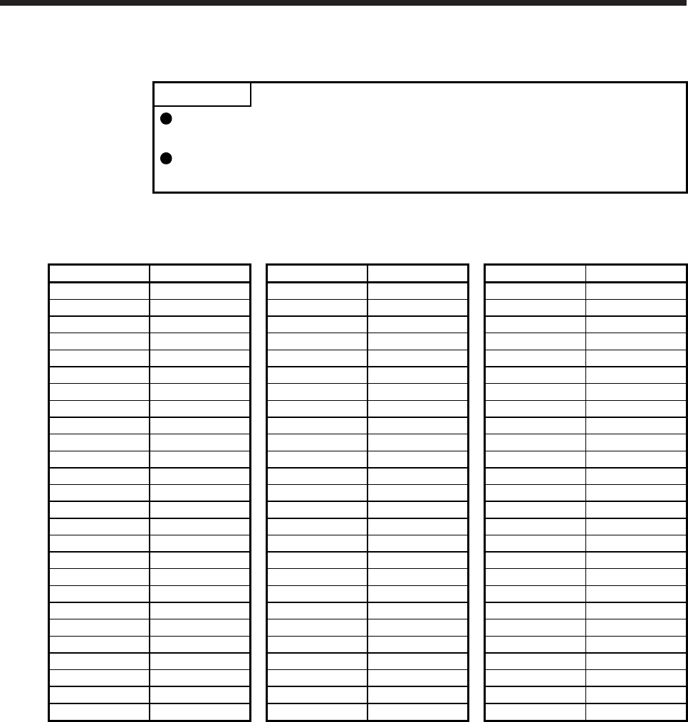
APPENDIX
App. - 27
App. 6 Selection example of servo motor power cable
POINT
Selection condition of wire size is as follows.
Wire length: 30 m or less
Some cables do not fit into the option or the recommended cable clamp. Select
a cable clamp according to the cable diameter.
Selection example when using the 600 V grade EP rubber insulated chloroprene sheath cab-tire cable
(2PNCT) for servo motor power (U, V, and W) is indicated below.
Servo motor Wire size [mm2] Servo motor Wire size [mm2] Servo motor Wire size [mm2]
HG-SR51 1.25 HG-JR503 5.5 HG-JR701M4 5.5
HG-SR81 1.25 HG-JR703 8 HG-JR11K1M4 8
HG-SR121 2 HG-JR903 14 HG-JR15K1M4 8
HG-SR201 2 HG-JR701M 8 HG-JR22K1M4 14
HG-SR301 3.5 HG-JR11K1M 14 HG-JR30K1M4 22
HG-SR421 5.5 HG-JR15K1M 22 HG-JR37K1M4 22
HG-SR52 1.25 HG-JR22K1M 30 HG-JR45K1M4 22
HG-SR102 1.25 HG-JR30K1M 50 HG-JR55K1M4 38
HG-SR152 2 HG-JR37K1M 60 HG-JR6014 5.5
HG-SR202 2 HG-JR601 8 HG-JR8014 5.5
HG-SR352 3.5 HG-JR801 8 HG-JR12K14 8
HG-SR502 5.5 HG-JR12K1 14 HG-JR15K14 8
HG-SR702 8 HG-JR15K1 14 HG-JR20K14 8
HG-SR524 1.25 HG-JR20K1 30 HG-JR25K14 8
HG-SR1024 1.25 HG-JR25K1 30 HG-JR30K14 14
HG-SR1524 2 HG-JR30K1 38 HG-JR37K14 22
HG-SR2024 2 HG-JR37K1 60 HG-RR103 2
HG-SR3524 2 HG-JR534 1.25 HG-RR153 2
HG-SR5024 3.5 HG-JR734 2 HG-RR203 (Note) 3.5
HG-SR7024 5.5 HG-JR1034 2 HG-RR353 (Note) 5.5
HG-JR53 1.25 HG-JR1534 2 HG-RR503 (Note) 5.5
HG-JR73 1.25 HG-JR2034 2 HG-UR72 1.25
HG-JR103 2 HG-JR3534 5.5 HG-UR152 2
HG-JR153 2 HG-JR5034 5.5 HG-UR202 3.5
HG-JR203 2 HG-JR7034 8 HG-UR352 5.5
HG-JR353 3.5 HG-JR9034 8 HG-UR502 5.5
Note. Use a composite cable and others when combining with wiring of the electromagnetic brake power in the same cable.
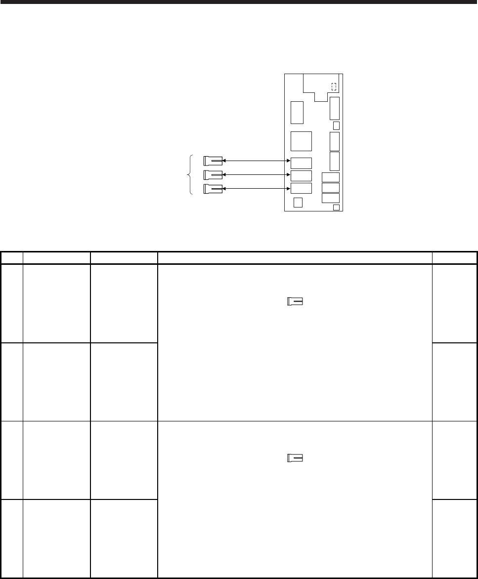
APPENDIX
App. - 28
App. 7 Crimping connector for CNP3_
CNP3B
CNP3C (Note)
CNP3A
1)2)3)4)
MR-J4W_-_B
Servo amplifier
Note. This figure shows the 3-axis servo amplifier.
No. Name Model Description Application
1) Connector set MR-J3WCNP3-
DL
The connector set is used for connecting to the servo amplifier directly using
MR-PWS1CBL_M-_.
For CNP3A/CNP3B/CNP3C
Receptacle housing: F35FDC-04V-K
Receptacle contact: LF3F-41GF-P2.0
(JST)
Applicable wire
Wire size: 0.75 mm2 (AWG 19) to 1.25 mm2 (AWG 16)
Insulator OD: 1.8 mm to 2.8 mm
The crimping tool (YRF-880) is required.
Quantity: 1
For thin
wire
2) Connector set MR-J3WCNP3-
DL-20P
Quantity:
20
For thin
wire
3) Connector set MR-J3WCNP3-
D2L
The connector set is used for connecting to the servo amplifier directly
without using MR-PWS1CBL_M-_.
For CNP3A/CNP3B/CNP3C
Receptacle housing: F35FDC-04V-K
Receptacle contact: BF3F-71GF-P2.0
(JST)
Applicable wire
Wire size: 1.25 mm2 (AWG 16) to 2.0 mm2 (AWG 14)
Insulator OD: 2.4 mm to 3.4 mm
The crimping tool (YRF-1070) is required.
Quantity: 1
For thick
wire
4) Connector set MR-J3WCNP3-
D2L-20P
Quantity:
20
For thick
wire
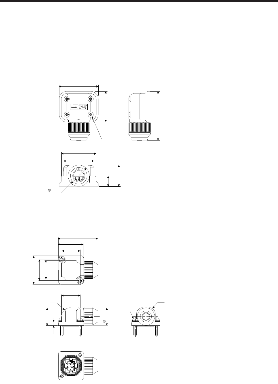
APPENDIX
App. - 29
App. 8 Connector dimensions
The connector dimensions for wiring the servo motor are shown below.
(1) TE Connectivity
2174053-1
[Unit: mm]
19.6
13.5
6.5
24.6
22
19
31.1
(Note)
13.6
Note. The recommended screw tightening torque is
0.1 N•m.
Crimping tool: 1596970-1 (for ground clip)
1596847-1 (for receptacle contact)
(2) JAE
JN4FT02SJ1-R
[Unit: mm]
26.6
17
12.3
19
14.3
12.5
12.7
R6
11.6
11.8
2.5
R4
(Note)
Note. The recommended screw tightening torque is
0.2 N•m.
Crimping tool: CT170-14-TMH5B
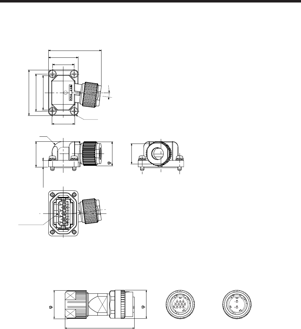
APPENDIX
App. - 30
KN4FT04SJ1-R
[Unit: mm]
16 ± 0.3
11.7 ± 0.2
Approx. 29
18.5 ± 0.3
24.5 ± 0.3
20.1 ± 0.2
7°
3.5 ± 0.2
12.2 ± 0.3
13.7 ± 0.3
11 ± 0.3
13 ± 0.3
Main key
(Note)
R6
Note. The recommended screw tightening torque is
0.2 N•m.
Crimping tool: CT170-14-TMH5B
(3) DDK
(a) CMV1-SP10S-M_/CMV1-SP2S-_
Refer to section 3.3 for details of crimping tools.
[Unit: mm]
CMV1-SP2S-_CMV1-SP10S-M_
Approx. 50
21
21
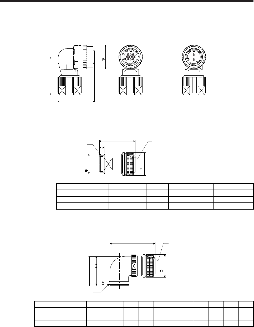
APPENDIX
App. - 31
(b) CMV1-AP10S-M_/CMV1-AP2S-_
Refer to section 3.3 for details of crimping tools.
[Unit: mm]
CMV1-AP10S-M_ CMV1-AP2S-_
21
Approx. 32
Approx. 33
(c) CE05-6A_-_SD-D-BSS
[Unit: mm]
C ± 0.8
B0
-0.38
D or shorte
r
7.85 or longer
WA
Model A B C D W
CE05-6A18-10SD-D-BSS 1 1/8-18UNEF-2B 34.13 32.1 57 1-20UNEF-2A
CE05-6A22-22SD-D-BSS 1 3/8-18UNEF-2B 40.48 38.3 61 1 3/16-18UNEF-2A
CE05-6A32-17SD-D-BSS 2-18UNS-2B 56.33 54.2 79 1 3/4-18UNS-2A
(d) CE05-8A_-_SD-D-BAS
[Unit: mm]
D or shorte
r
A
Y or longer
W
Approx. S ± 1
U ± 0.7 R ± 0.7
B0
-0.38
Model A B D W R U S Y
CE05-8A18-10SD-D-BAS 1 1/8-18UNEF-2B 34.13 69.5 1-20UNEF-2A 13.2 30.2 43.4 7.5
CE05-8A22-22SD-D-BAS 1 3/8-18UNEF-2B 40.48 75.5 1 3/16-18UNEF-2A 16.3 33.3 49.6 7.5
CE05-8A32-17SD-D-BAS 2-18UNS-2B 56.33 93.5 1 3/4-18UNS-2A 24.6 44.5 61.9 8.5
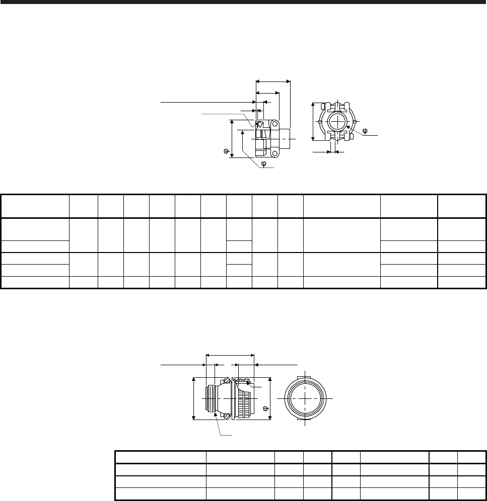
APPENDIX
App. - 32
(e) CE3057-_A-_-D
[Unit: mm]
(Bushing ID)
Effective thread length C
V threads 1.6
Approx. D
(Movable range on one side)
(Cable clamp ID)
H
F
E
B ± 0.7
A ± 0.7
G ± 0.7
Model Shell
size A B C D E F G H V Bushing Cable
OD
CE3057-10A-1-D 18 23.8 30.1 10.3 41.3 15.9 14.1 31.7 3.2 1-20UNEF-2B CE3420-10-1 10.5 to
14.1
CE3057-10A-2-D 11.0 CE3420-10-2 8.5 to 11
CE3057-12A-1-D 22 23.8 35 10.3 41.3 19 16.0 37.3 4.0 1 3/16-18UNEF-2B
CE342012-1 12.5 to 16
CE3057-12A-2-D 13.0 CE342012-2 9.5 to 13
CE3057-20A-1-D 32 27.8 51.6 11.9 43 31.7 23.8 51.6 6.3 1 3/4-18UNS-2B CE3420-20-1 22 to 23.8
(f) D/MS3106B_-_S
[Unit: mm]
L or shorter
W or longer
A
V
Y or shorter
J ± 0.12
Q 0
-0.38
Model A J L Q V W Y
D/MS3106B18-10S 1 1/8-18UNEF 18.26 52.37 34.13 1-20UNEF 9.53 42
D/MS3106B22-22S 1 3/8-18UNEF 18.26 56.57 40.48 1 3/16-18UNEF 9.53 50
D/MS3106B32-17S 2-18UNS 18.26 61.92 56.33 1 3/4-18UNS 11.13 66
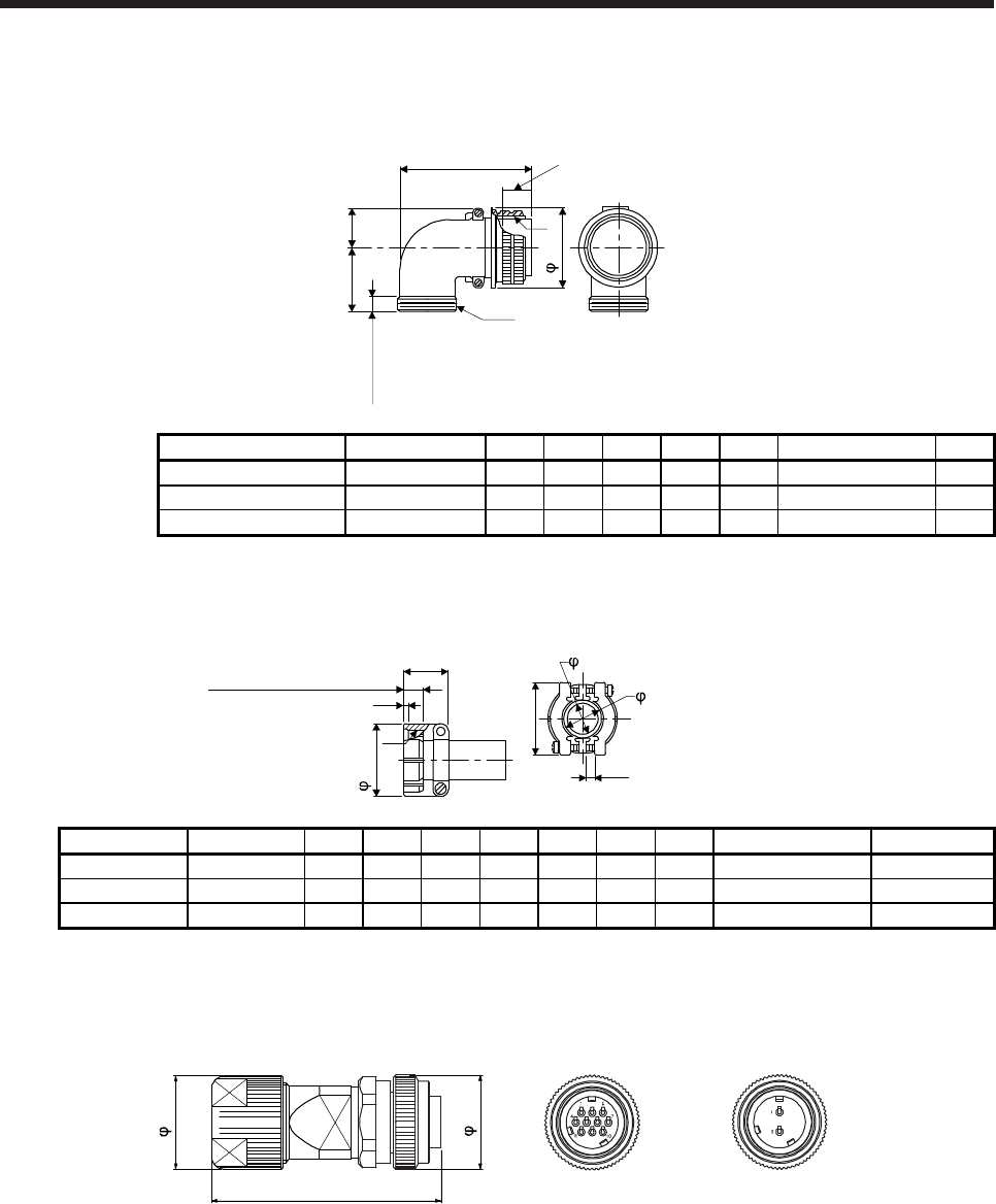
APPENDIX
App. - 33
(g) D/MS3108B_-_S
[Unit: mm]
L or shorter
V
A
W or longer
J ± 0.12
R ± 0.5U ± 0.5
Q 0
-0.38
Model A J L Q R U V W
D/MS3108B18-10S 1 1/8-18UNEF 18.26 68.27 34.13 20.5 30.2 1-20UNEF 9.53
D/MS3108B22-22S 1 3/8-18UNEF 18.26 76.98 40.48 24.1 33.3 1 3/16-18UNEF-2A 9.53
D/MS3108B32-17S 2-18UNS 18.26 95.25 56.33 32.8 44.4 1 3/4-18UNS 11.13
(h) D/MS3057-_A
[Unit: mm]
Effective thread length C
B ± 0.7
A ± 0.7
G ± 0.7
1.6 D (Cable clamp ID)
V
F (Movable range)
E (Bushing ID)
Model Shell size A B C D E F G V Bushing
D/MS3057-10A 18 23.8 30.1 10.3 15.9 14.3 3.2 31.7 1-20UNEF AN3420-10
D/MS3057-12A 22 23.8 35.0 10.3 19.0 15.9 4.0 37.3 1 3/16-18UNEF-2A AN3420-12
D/MS3057-20A 32 27.8 51.6 11.9 31.7 23.8 6.3 51.6 1 3/4-18UNS AN3420-20
(i) CMV1S-SP10S-M_/CMV1S-SP2S-_
Refer to section 3.3 for details of crimping tools.
[Unit: mm]
CMV1S-SP2S-_CMV1S-SP10S-M_
Approx. 50
21
21
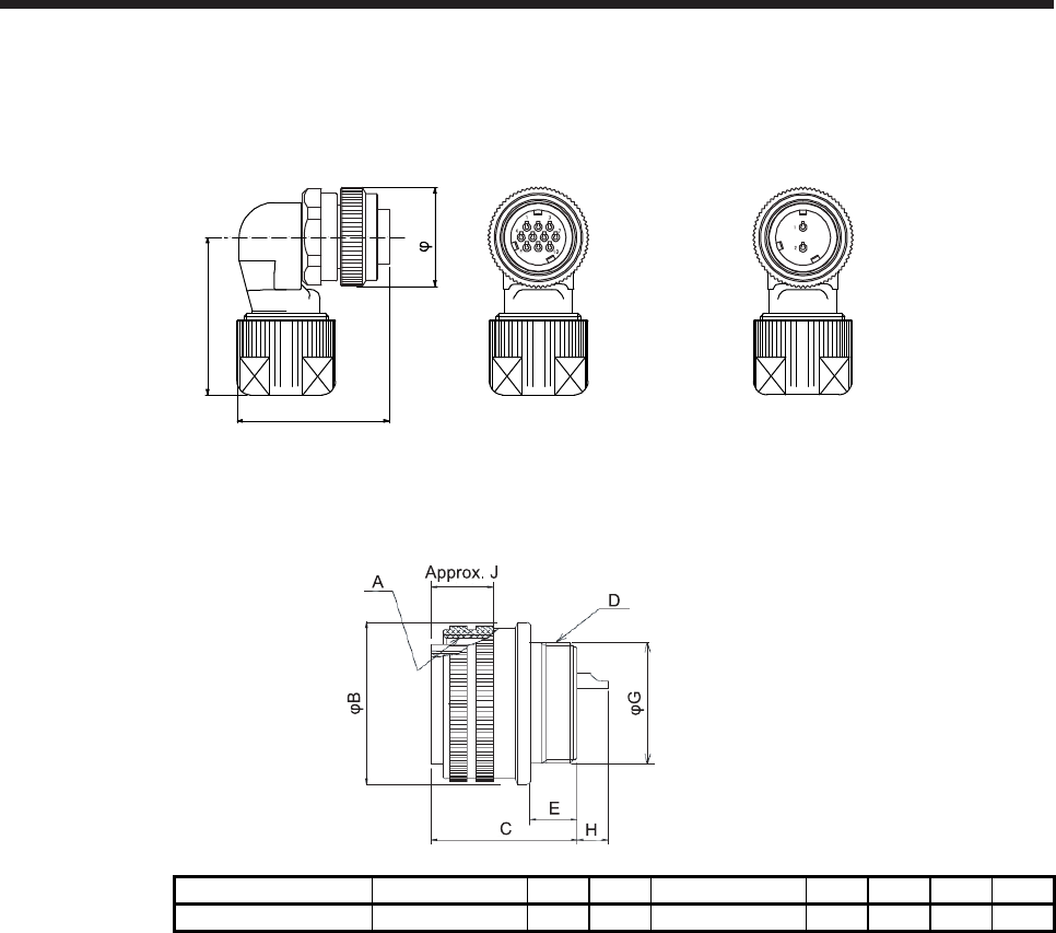
APPENDIX
App. - 34
(j) CMV1S-AP10S-M_/CMV1S-AP2S-_
Refer to section 3.3 for details of crimping tools.
[Unit: mm]
CMV1S-AP10S-M_ CMV1S-AP2S-_
Approx. 32
Approx. 33
21
(k) CE05-6A32-17SD-D
[Unit: mm]
Model A B C D E G H J
CE05-6A32-17SD-D 2-18UNS-2B 56.33 37.0 1 7/8-16UN-2A 13.14 45.3 9.2 19.4
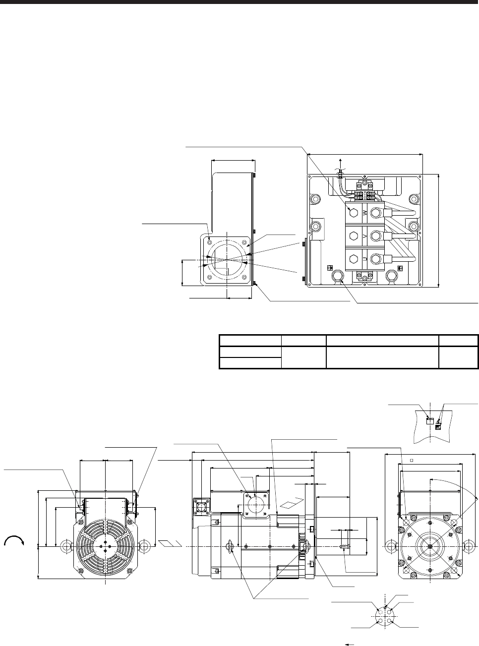
APPENDIX
App. - 35
App. 9 HG-JR22K1M(4) appearance change
The appearance of the HG-JR22K1M(4) servo motor has been changed since September 2014. The
following shows the terminal box detail diagram and dimensions before change.
(1) Terminal box detail diagram (HG-JR22K1M(4))
[Unit: mm]
Approx. 235
Approx. 230
Approx. 88.6
Protective earth (PE) terminal: M10 screw (2)
Power supply terminal block: M10 screw (3)
Terminal box lid: M4 screw (8)
Approx. 52.5
φ63 hole
φ80 hole
Terminal box side
Keep plate
Keep plate side
Keep plate: M5 screw (4)
Approx. 50.5
Connected to the
encoder connector
(2) Dimensions
Model Output [kW] Moment of inertia J [× 10-4 kg•m2] Mass [kg]
HG-JR22K1M 22 489 120
HG-JR22K1M4
[Unit: mm]
Caution plate
Motor plate
BV
BW
(Red)
(White)
(Black)
Cooling fan
rotation
direction
BU
Key
To be left open
4-φ24 mounting hole
Use hexagon socket
head cap screw.
φ65m6
φ230h7
250 (Flange)
352
140
Intake
Exhaust
5
476
174230
Approx. 37
35
220125
154
154
107101
190
825
M12 screw
Eyebolt (Note 1,2)
Power lead hole
Encoder connector
MS3102A20-29P
Cooling fan connector
CE05-2A14S-2P 235
439
130
Oil seal
Motor plate/Caution plate
φ63 227
163
45°
φ265
φ330
4 in total
Bottom
Bottom
Top
Bottom
Top
A
BC
D
Cooling fan connector viewed from the connection side
Motor flange direction BC37772A
Top
Note 1. When the motor is used without the eyebolt, plug the threaded hole with a bolt of M12 × 20 or less.
2.
A
n angle adjusting washer is inserted into the eyebolt.

REVISION
*The manual number is given on the bottom left of the back cover.
Print Data *Manual Number Revision
Mar. 2012 SH(NA)030113-A First edition
Jun. 2012 SH(NA)030113-B 4. Additional instructions
(1) Transportation and
installation
Section 2.2
Section 2.6 (2)
Section 5.1.2
Section 6.3.1
Section 6.6.1 (2)
Section 6.6.2 (2)
Section 7.3.1
Section 7.6.1 (2)
Section 7.6.2 (2)
The part of table is changed.
The sentences are added to CAUTION.
The sentences are added.
The sentences of Note are changed.
The part of table is changed.
The part of table is changed.
The part of table is changed.
The part of table is changed.
The part of table is changed.
The part of table is changed.
Feb. 2013 SH(NA)030113-C 4. Additional instructions
(1) Transportation and
installation
Section 1.1
Section 1.2 (3) (4)
Section 2.1 (1)
Section 2.2 to Section 2.10
Section 3.1 (3) to (5)
Section 3.4
Chapter 4
Section 4.2.2
Section 4.3
Section 4.4
Chapter 5
Section 5.1.1 (2)
Section 5.1.1 (3)
Section 5.1.2
Section 5.2 (2)
Section 5.2 (4)
Section 5.2 (6)
Section 5.5
Section 6.2
Section 6.3.1
Section 6.8
Section 7.1
Section 7.2
Section 7.3.1
Section 7.3.2 (2)
Section 7.4
Section 7.5
Section 7.6
Section 7.7
Chapter 8
Chapter 9
Chapter 10
Appendix 1
Appendix 2
The part of table is changed.
The part of diagram is changed.
Addition
The part of table is changed.
A part is newly added, construction of sentences is changed.
Addition
Addition
POINT is added.
A part is newly added, construction of sentences is changed.
A part is newly added, construction of sentences is changed.
A part is newly added, construction of sentences is changed.
POINT is added.
The part of diagram is changed.
Addition
The part of table is changed.
POINT is changed.
The part of diagram is changed.
Addition
The part of table is changed.
The part of table is changed.
The part of table is changed.
The part of diagram is changed.
The part of diagram is changed.
The sentences of Note 1 are changed.
The part of table is changed.
The part of table is changed.
Addition
The part of table is changed.
The part of table is changed.
The part of table is changed.
The part of table is changed.
The part of diagram is changed.
Addition
Addition
Addition
The part of table is changed.
The part of table is changed.

Print Data *Manual Number Revision
Feb. 2013 SH(NA)030113-C Appendix 4
Appendix 5.9 (8) to (10)
Appendix 6
The part of table is changed.
Some numbers are changed.
The part of table is changed.
Jun. 2013 SH(NA)030113-D "The following servo amplifiers will be available in the future. All specifications of followings may be
changed without notice. MR-J4-_B(4)-RJ020" is deleted.
Aug. 2013 SH(NA)030113-E Section 4.4
Section 8.2
The part of table is changed.
The part of table is changed.
Oct. 2013 SH(NA)030113-F MR-BT6VCBL03M is added.
Section 1.1
Section 5.1.1
Section 5.1.2
Section 5.2 (7)
Section 6.4
Section 7.4
Section 8.4
Section 9.4
Section 10.4
The sentences are added.
The part of diagram is changed.
The part of table is changed.
Addition
The sentences of Note 7 are added.
The sentences of Note 7 are added.
The sentences of Note 7 are added.
The sentences of Note 7 are added.
The sentences of Note 7 are added.
Mar. 2014 SH(NA)030113-G 1-phase 100 V AC of servo amplifier power supply input is added to torque characteristics of
HG-MR and HG-KR servo motors.
Section 4.4
Section 6.2
Section 6.3.2
Section 7.2 (2)
Section 8.2
Appendix 3.1
The part of table is changed.
The part of table is changed.
The part of graph is changed.
The part of table is changed.
The part of table is changed.
The sentences are added.
Jan. 2015 SH(NA)030113-H HG-JR701M(4), HG-JR30K1M(4), HG-JR37K1M(4), HG-JR45K1M4, HG-JR55K1M4, and HG-JR
1000 r/min series are added.
1. To prevent electric shock,
note the following
4. Additional instructions
(1) Transportation and
installation
4. Additional instructions
(2) Wiring
4. Additional instructions
(4) Usage
Section 1.1
Section 1.2 (2)
Section 1.2 (3)
Section 2.8
Section 2.9
Section 3.1 (3)
Section 3.4
Chapter 4
Section 4.2.2 (2) (b)
Section 4.2.2 (3)
Section 4.2.2 (4)
Section 4.3 (3)
Section 4.4
Chapter 5
Section 5.1.1 (2)
Section 5.1.1 (3)
The part of sentences is changed.
The part of table is changed.
The part of sentences is changed.
The part of sentences is changed.
The diagram is changed.
The title is changed.
The title is changed.
The diagram is changed.
The part of sentences is changed.
The sentences are added to CAUTION.
The part of table is changed.
The part of sentences is changed.
The part of diagram is changed.
The part of table is changed.
The part of diagram is changed.
The part of table is changed.
The part of sentences is changed.
The sentences are added to POINT.
The part of table is changed.
The part of table is changed.
The diagram is changed.
The table are added.
The sentences are added to POINT.
The part of sentences is changed.
The sentences are added to CAUTION.
The sentences are added to POINT.
The title is changed.
The title is changed.
The diagram is changed.

Print Data *Manual Number Revision
Jan. 2015 SH(NA)030113-H Section 5.1.2
Section 5.2 (1) (a)
Section 5.2 (2) (a)
Section 5.2 (5) (a)
Section 5.2 (6)
Section 5.2 (6) (a)
Section 5.2 (6) (b)
Section 6.3.1
Section 6.3.2
Section 6.6
Section 7.3.1
Section 7.3.2
Section 7.6
Chapter 8
Section 8.1
Section 8.2
Section 8.3.1
Section 8.3.2
Section 8.4
Section 8.5
Section 8.6
Section 8.7
Section 8.8.1
Section 8.8.2
Section 8.8.3
Section 9.3.1
Section 9.3.2
Section 10.3.1
Section 10.3.2
Appendix 1
Appendix 4 (1)
Appendix 4 (2) (c)
Appendix 6
Appendix 9
The part of table is changed.
The sentences are added.
The sentences are added.
The sentences are added.
The part of sentences is changed.
The sentences are added.
The sentences of Note 2 are changed.
The sentences are added.
The part of sentences is changed.
The part of sentences is changed.
The sentences are added.
The part of sentences is changed.
The part of sentences is changed.
The part of sentences is changed.
The part of diagram is changed.
The title is changed.
The table are added.
The part of table is changed.
The table are added.
The sentences are added.
The part of sentences is changed.
The diagram are added.
The part of sentences is changed.
The part of table is changed.
The part of table is changed.
The diagram are added.
The part of table is changed.
The part of table is changed.
The diagram is changed.
The diagram are added.
The part of table is changed.
The part of diagram is changed.
The diagram are added.
The part of table is changed.
The part of diagram is changed.
The sentences are added.
The part of sentences is changed.
The sentences are added.
The part of sentences is changed.
The part of table is changed.
The part of table is changed.
The table are added.
The part of table is changed.
Addition
Apr. 2015 SH(NA)030113-J Servo motors with functional safety and HG-AK series servo motor are added.
4. Additional instructions
Section 1.1 (2)
Section 1.2 (4)
Section 1.5
Section 2.1
Section 2.8
Section 3.1 (6)
Section 3.2
Section 3.4
Section 4.1
Section 4.2.2
Section 4.2.3
Section 4.3 (6)
Section 4.4
Section 5.1.1 (4)
Section 5.1.2
Partially added.
Added.
Added.
Added.
Partially added.
CAUTION is added.
Added.
Partially changed.
Partially added.
Partially added.
Partially changed.
Added.
Added.
Partially added.
Added.
Partially added.

Print Data *Manual Number Revision
Apr. 2015 SH(NA)030113-J Section 5.2 (8)
Section 5.4
Section 5.5
Section 5.6
Section 6.1
Section 7.1
Section 8.1
Chapter 11
App. 1
App. 4 (1) (2)
App. 8
Added.
Added.
Partially changed.
Partially added.
Partially added.
Partially added.
Partially added.
Added.
Partially added.
Partially added.
Partially changed.
This manual confers no industrial property rights or any rights of any other kind, nor does it confer any patent licenses.
Mitsubishi Electric Corporation cannot be held responsible for any problems involving industrial property rights which
may occur as a result of using the contents noted in this manual.
2012 MITSUBISHI ELECTRIC CORPORATION

MEMO

MELSERVO is a trademark or registered trademark of Mitsubishi Electric Corporation in Japan and/or other countries.
QR Code is a trademark or a registered trademark of DENSO WAVE INCORPORATED in Japan, the United States and/or other
countries.
All other product names and company names are trademarks or registered trademarks of their respective companies.
Countr
y
/Re
g
ion Sales office Tel/Fax
USA MITSUBISHI ELECTRIC AUTOMATION, INC.
500 Corporate Woods Parkway, Vernon Hills, IL 60061, U.S.A.
Tel
Fax : +1-847-478-2100
: +1-847-478-2253
Mexico MITSUBISHI ELECTRIC AUTOMATION, INC. Mexico Branch
Mariano Escobedo #69, Col. Zona Industrial, Tlalnepantla Edo, C.P.54030, Mexico
Tel
Fax : +52-55-3067-7500
: –
Brazil MITSUBISHI ELECTRIC DO BRASIL COM
É
RCIO E SERVIÇOS LTDA.
Rua Jussara, 1750- Bloco B Anexo, Jardim Santa Cecilia, CEP 06465-070, Barueri -
SP, Brasil
Tel
Fax : +55-11-4689-3000
: +55-11-4689-3016
German
y
MITSUBISHI ELECTRIC EUROPE B.V. German Branch
Gothaer Strasse 8, D-40880 Ratingen, Germany
Tel
Fax : +49-2102-486-0
: +49-2102-486-1120
UK MITSUBISHI ELECTRIC EUROPE B.V. UK Branch
Travellers Lane, Hatfield, Hertfordshire, AL10 8XB, U.K.
Tel
Fax : +44-1707-28-8780
: +44-1707-27-8695
Ital
y
MITSUBISHI ELECTRIC EUROPE B.V. Italian Branch
Centro Direzionale Colleoni - Palazzo Sirio Viale Colleoni 7, 20864 Agrate Brianza
(Milano) Italy
Tel
Fax : +39-039-60531
: +39-039-6053-312
Spain MITSUBISHI ELECTRIC EUROPE, B.V. Spanish Branch
Carretera de Rubí, 76-80-Apdo. 420, 08173 Sant Cugat del Vallés (Barcelona),
S
p
ain
Tel
Fax : +34-935-65-3131
: +34-935-89-1579
France MITSUBISHI ELECTRIC EUROPE B.V. French Branch
25, Boulevard des Bouvets, F-92741 Nanterre Cedex, France
Tel
Fax : +33-1-55-68-55-68
: +33-1-55-68-57-57
Czech Republic MITSUBISHI ELECTRIC EUROPE B.V. Czech Branch
A
venir Business Park, Radlicka 751/113e, 158 00 Praha5, Czech Republic
Tel
Fax : +420-251-551-470
: +420-251-551-471
Poland MITSUBISHI ELECTRIC EUROPE B.V. Polish Branchul.
Krakowska 50, 32-083 Balice, Poland
Tel
Fax : +48-12-630-47-00
: +48-12-630-47-01
Russia MITSUBISHI ELECTRIC EUROPE B.V. Russian Branch St. Petersburg office
Piskarevsky pr. 2, bld 2, lit “Sch”, BC “Benua”, office 720; RU-195027 St. Petersburg,
Russia
Tel
Fax : +7-812-633-3497
: +7-812-633-3499
Sweden MITSUBISHI ELECTRIC EUROPE B.V. (Scandinavia)
Fjelievägen 8, SE-22736 Lund, Sweden
Tel
Fax : +46-8-625-10-00
: +46-46-39-70-18
Turke
y
MITSUBISHI ELECTRIC TURKEY A.Ş
Ü
mraniye Branch
Şerifali Mahallesi Nutuk Sokak No:5, TR-34775 Ümraniye, İstanbul, Türkey
Tel
Fax : +90-216-526-3990
: +90-216-526-3995
UAE MITSUBISHI ELECTRIC EUROPE B.V. Dubai Branch
Dubai Silicon Oasis, P.O.BOX 341241, Dubai, U.A.E.
Tel
Fax : +971-4-3724716
: +971-4-3724721
South Africa
A
DROIT TECHNOLOGIES
20 Waterford Office Park, 189 Witkoppen Road, Fourways, Johannesburg, South
A
frica
Tel
Fax : +27-11-658-8100
: +27-11-658-8101
China MITSUBISHI ELECTRIC AUTOMATION (CHINA) LTD.
No.1386 Hongqiao Road, Mitsubishi Electric Automation Center, Shanghai, China
Tel
Fax : +86-21-2322-3030
: +86-21-2322-3000
Taiwan SETSUYO ENTERPRISE CO., LTD.
6F, No.105, Wugong 3rd Road, Wugu District, New Taipei City 24889, Taiwan,
R.O.C.
Tel
Fax : +886-2-2299-2499
: +886-2-2299-2509
Korea MITSUBISHI ELECTRIC AUTOMATION KOREA CO., LTD.
7F-9F, Gangseo Hangang Xi-tower A, 401, Yangcheon-ro, Gangseo-Gu, Seoul
157-801, Korea
Tel
Fax : +82-2-3660-9510
: +82-2-3664-8372/8335
Singapore MITSUBISHI ELECTRIC ASIA PTE. LTD.
307, Alexandra Road, Mitsubishi Electric Building, Singapore 159943
Tel
Fax : +65-6473-2308
: +65-6476-7439
Thailand MITSUBISHI ELECTRIC FACTORY AUTOMATION (THAILAND) CO., LTD.
12th Floor, SV.City Building, Office Tower 1, No. 896/19 and 20 Rama 3 Road,
Kwaeng Bangpongpang, Khet Yannawa, Bangkok 10120, Thailand
Tel
Fax : +66-2682-6522 to 6531
: +66-2682-6020
Indonesia PT. MITSUBISHI ELECTRIC INDONESIA
Gedung Jaya 11th Floor, JL. MH. Thamrin No.12, Jakarta Pusat 10340, Indonesia
Tel
Fax : +62-21-3192-6461
: +62-21-3192-3942
Vietnam MITSUBISHI ELECTRIC VIETNAM COMPANY LIMITED
Unit 01-04, 10th Floor, Vincom Center, 72 Le Thanh Ton Street, District 1, Ho Chi
Minh City, Vietnam
Tel
Fax : +84-8-3910-5945
: +84-8-3910-5947
India MITSUBISHI ELECTRIC INDIA PVT. LTD. Pune Branch
Emerald House, EL -3, J Block, M.I.D.C Bhosari, Pune - 411026, Maharashtra, India
Tel
Fax : +91-20-2710-2000
: +91-20-2710-2100
A
ustralia MITSUBISHI ELECTRIC AUSTRALIA PTY. LTD.
348 Victoria Road, P.O. Box 11, R
y
dalmere, N.S.W 2116, Australia Tel
Fax : +61-2-9684-7777
: +61-2-9684-7245

Warranty
1. Warranty period and coverage
We will repair any failure or defect hereinafter referred to as "failure" in our FA equipment hereinafter referred to as the "Product"
arisen during warranty period at no charge due to causes for which we are responsible through the distributor from which you
purchased the Product or our service provider. However, we will charge the actual cost of dispatching our engineer for an on-site
repair work on request by customer in Japan or overseas countries. We are not responsible for any on-site readjustment and/or trial
run that may be required after a defective unit are repaired or replaced.
[Term]
The term of warranty for Product is twelve (12) months after your purchase or delivery of the Product to a place designated by you or
eighteen (18) months from the date of manufacture whichever comes first (“Warranty Period”). Warranty period for repaired Product
cannot exceed beyond the original warranty period before any repair work.
[Limitations]
(1) You are requested to conduct an initial failure diagnosis by yourself, as a general rule.
It can also be carried out by us or our service company upon your request and the actual cost will be charged. However, it will not be
charged if we are responsible for the cause of the failure.
(2) This limited warranty applies only when the condition, method, environment, etc. of use are in compliance with the terms and
conditions and instructions that are set forth in the instruction manual and user manual for the Product and the caution label affixed
to the Product.
(3) Even during the term of warranty, the repair cost will be charged on you in the following cases;
(i) a failure caused by your improper storing or handling, carelessness or negligence, etc., and a failure caused by your hardware
or software problem
(ii) a failure caused by any alteration, etc. to the Product made on your side without our approval
(iii) a failure which may be regarded as avoidable, if your equipment in which the Product is incorporated is equipped with a safety
device required by applicable laws and has any function or structure considered to be indispensable according to a common
sense in the industry
(iv) a failure which may be regarded as avoidable if consumable parts designated in the instruction manual, etc. are duly
maintained and replaced
(v) any replacement of consumable parts (battery, fan, smoothing capacitor, etc.)
(vi) a failure caused by external factors such as inevitable accidents, including without limitation fire and abnormal fluctuation of
voltage, and acts of God, including without limitation earthquake, lightning and natural disasters
(vii) a failure generated by an unforeseeable cause with a scientific technology that was not available at the time of the shipment of
the Product from our company
(viii) any other failures which we are not responsible for or which you acknowledge we are not responsible for
2. Term of warranty after the stop of production
(1) We may accept the repair at charge for another seven (7) years after the production of the product is discontinued. The
announcement of the stop of production for each model can be seen in our Sales and Service, etc.
(2) Please note that the Product (including its spare parts) cannot be ordered after its stop of production.
3. Service in overseas countries
Our regional FA Center in overseas countries will accept the repair work of the Product. However, the terms and conditions of the
repair work may differ depending on each FA Center. Please ask your local FA center for details.
4. Exclusion of responsibility for compensation against loss of opportunity, secondary loss, etc.
Whether under or after the term of warranty, we assume no responsibility for any damages arisen from causes for which we are not
responsible, any losses of opportunity and/or profit incurred by you due to a failure of the Product, any damages, secondary
damages or compensation for accidents arisen under a specific circumstance that are foreseen or unforeseen by our company, any
damages to products other than the Product, and also compensation for any replacement work, readjustment, start-up test run of
local machines and the Product and any other operations conducted by you.
5. Change of Product specifications
Specifications listed in our catalogs, manuals or technical documents may be changed without notice.
6. Application and use of the Product
(1) For the use of our General-Purpose AC Servo, its applications should be those that may not result in a serious damage even if any
failure or malfunction occurs in General-Purpose AC Servo, and a backup or fail-safe function should operate on an external system
to General-Purpose AC Servo when any failure or malfunction occurs.
(2) Our General-Purpose AC Servo is designed and manufactured as a general purpose product for use at general industries.
Therefore, applications substantially influential on the public interest for such as atomic power plants and other power plants of
electric power companies, and also which require a special quality assurance system, including applications for railway companies
and government or public offices are not recommended, and we assume no responsibility for any failure caused by these
applications when used
In addition, applications which may be substantially influential to human lives or properties for such as airlines, medical treatments,
railway service, incineration and fuel systems, man-operated material handling equipment, entertainment machines, safety
machines, etc. are not recommended, and we assume no responsibility for any failure caused by these applications when used.
We will review the acceptability of the abovementioned applications, if you agree not to require a specific quality for a specific
application. Please contact us for consultation.
SH(NA)030113-J

SH (NA) 030113-J (1504) MEE Printed in Japan Specifications are subject to change without notice.
This Instruction Manual uses recycled paper.
MODEL
MODEL
CODE
General-Purpose AC Servo
SERVO MOTOR INSTRUCTION MANUAL (Vol. 3)
HEAD OFFICE : TOKYO BLDG MARUNOUCHI TOKYO 100-8310
MODEL
HG-MR
HG-KR
HG-SR
HG-JR
HG-RR
HG-UR
HG-AK
SERVO MOTOR INSTRUCTION MANUAL (Vol. 3)
1CW949
MOTOR INSTRUCTIONMANUAL(3SYU)
J
J
