Mobilarm 08 Tracking Device User Manual BOOK1 indd
Mobilarm Limited Tracking Device BOOK1 indd
Mobilarm >
Manual

FCC ID: SF5-08 Report No. M040642_Cert_Tx
EMC Technologies Pty Ltd – 57 Assembly Drive, Tullamarine VIC 3043 Australia
www.emctech.com.au
EMC Technologies Report Number: M040642_Cert_Tx
APPENDIX K – User Manual
MOBiLert Global System
Installation and Operation ManualInstallation and Operation Manual
MOBiLert Systems
MOBiLert Crewsafe 7000 Series
Ver. 0.1 Prerelease
This device complies with Part 15 of the FCC Rules. Operation is sub-
ject to the following two conditions: (1) this device may not cause
harmful interference, and (2) this device must accept any interference
received, including interference that may cause undesired operation.
Compliance information statement
NOTE
This equipment has been tested and found to comply with the limits for a Class
B digital device, pursuant to Part 15 of the FCC Rules. These limits are designed
to provide reasonable protection against harmful interference in a residential
installation. This equipment generates, uses and can radiate radio frequency
energy and, if not installed and used in accordance with the instructions, may
cause harmful interference to radio communications. However, there is no guar-
antee that nterference will not occur in a particular installation. If this equip-
ment does cause harmful interference to radio or television reception, which
can be determined by turning the equipment off and on, the user is encourage
to try to correct the interference by one or more of the following measures:
Reorient or relocate the receiving antenna
Increase the separation between the equipment and receiver
Connect the equipment into an outlet on a circuit different from that
to which the receiver is connected
Consult the dealer or an experienced radio/TV technician for help
WARNING
Any changes or modifications not expressively approved by MOBilarm Ltd. could
void the user’s authority to operate this equipment
MOBiLert CREWSAFE 7000 SERIES 3
WELCOME
MOBiLert Crewsafe 7000 Series
Installation and Operation Manual

Section One – Introducing your MOBiLert System 6
1.1 What is MOBiLert? 6
1.2 How it keeps you safe 6
1.3 What you have to do 6
1.4 What MOBiLert will do 6
1.5 What MOBiLert can not do 7
Section Two – Installing for best performance 8
Console
2.1 A short lesson in radio frequency propagation 8
2.2 Using the External Dipole Antenna 9
2.3 Finding the sweet spot 10
2.4 Testing for reliability 12
2.50 Mechanical considerations 15
2.51 Bracket mounting 15
2.52 Bulkhead flush mounting 16
2.60 Electrical considerations 19
2.61 Connection to essential services power 19
2.62 Connection to standard ships power 19
2.63 Keeping the cables out of trouble 20
2.64 Connection of the external alarm 21
Charger 22
2.7 How the charger does its thing 22
2.8 Finding the best spot 22
2.9 Testing for reliability 23
2.10 Mechanical considerations 23
2.11 Electrical considerations 24
PTX’s 25
2.12 How does the PTX work 25
2.13 Making it easy for the crew to use them 25
2.14 Some options for wearing them 25
Section Three – Using the system 27
3.10 PTX Status LED 27
3.11 Short Green flash once every 2 seconds: 27
CONTENTS

MOBiLert CREWSAFE 7000 SERIES 5
CONTENTS
3.12 Short Red flash once every 2 seconds: 27
3.13 Long Orange flash once every 5 seconds: 27
3.14 Red on hard: 27
3.15 LED is off: 27
3.20 Charger Status LED 27
3.21 Long Green flash once every 3 seconds: 27
3.22 Quick alternating Red and Green flash. 28
3.23 LED is off: 28
3.30 Controls on the Console Unit 29
3.31 What the buttons do 29
3.32 Powering up the display 30
3.40 Normal Operation – PTX Status Screen 31
3.50 MOB screen 33
3.60 Recharging the PTX 35
3.70 Switching the PTXs off and on. 36
Section Four – Making changes to MOBiLert 37
4.10 Changing the screen settings 37
4.11 Contrast 37
4.12 Backlight 38
4.20 System Setup 38
4.30 Configuring the remote alarms 39
Section Five – Appendices
5.10 Console bulkhead mounting template 44
5.20 Console connection diagram 45
5.30 Charger connection diagram 46
5.40 MFP 0012 Console - Technical Specifications 48
5.50 MFP 0013 Charger Technical Specifications 48
5.60 MFP 0015 Pendant Technical Specifications 49
5.70 EC Declaration of conformity 50

Section One
1.0 Introducing your MOBiLert System
1.1 What is MOBiLert?
MobiLert is a dedicated system designed to help prevent loss of life
at sea. The system uses personal radio transmitters to maintain a
constant link with a central Console Unit. The moment a PTX is out
of radio range for more than 7 seconds, an alarm is sounded and the
exact GPS position is logged. The MobiLert Console will then auto-
matically switch to a track back screen giving the direction and range
back to the victim.
1.2 How it keeps you safe
Every PTX sends out a constant radio heartbeat to the Console.
Providing your crew is wearing a PTX you can be sure that they are
within about 30 Meters of the boat. MOBiLert is an active system. Any
flat batteries, broken PTXs or failures in the transmission system will
result in an alarm.
1.3 What you have to do
As the Captain, crew safety is your responsibility.
This system will only work if it is turned on and all of your crew are
wearing PTXs. Make sure that PTXs are easy to find, you have enough
on board and every one knows how to respond to an MOB emergen-
cy.
1.4 What MOBiLert will do
MOBiLert will give the Captain piece o f mind that all crew are safely
onboard. We have put a lot of effort into making the PTX small, tough
and easy to wear. Providing they are worn properly by the crew, the
system will keep track of the PTXs
proximity and the battery condition. In the event of a MOB Emer-
gency, MOBiLert will log the position that the PTX went missing and
provide the helmsman with instructions on how to get back to the
MOB position.

MOBiLert CREWSAFE 7000 SERIES 7
SECTION ONE
1.5 What MOBiLert can not do
MOBiLert can not replace good safety practices and procedures. MO-
BiLert won’t stop people falling overboard, can’t stop them drowning
and has only limited ability to find them when they are in the water.
MOBiLert should be considered the last line of defense
Section Two
Installing for best performance
2.1 A short lesson in radio frequency propagation.
The biggest benefit of the way we have done things is that the sys-
tem is fail-safe. Any prolonged breaks in the radio link will result in an
alarm. So, to make it free of false alarms we need to put some thought
into the installation. The system uses a radio link in the UHF range so
the link needs to be more or less “line of sight”. This is similar to the
ships VHF radio. (At UHF frequencies, the signals can bounce off metal
and water which means that occasionally it can see around corners but
we don’t want to count on it.)
The other property of the system is that it has some ability to see
through Fiberglass and wood. It is blocked completely by aluminum
and steel so if your boat is made from these materials you have to be
very careful where the Console is mounted and look at using Repeater
Antennas to cover any blind spots.
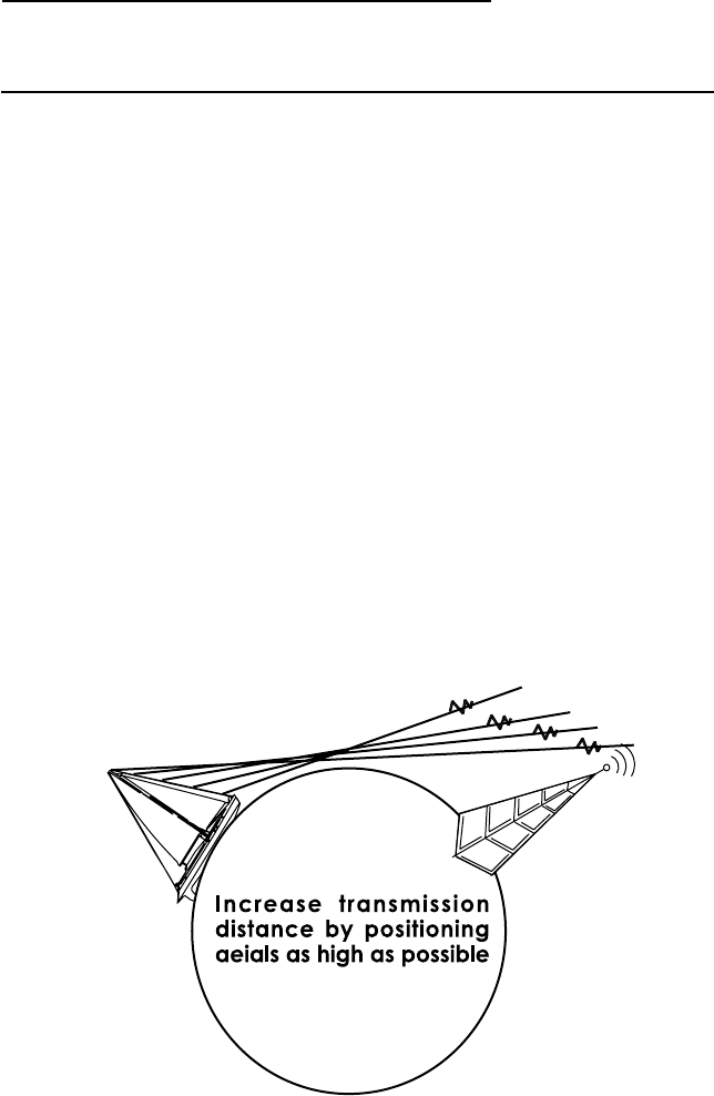
The higher you are the further you can see. Just like the Ships VHF
radio, the higher you can install the Console’s antennas the stronger
the link to the Pendants will be. However, you still have to be able to
read the Console particularly in a MOB Emergency as it will tell you how
to steer back to the MOB location.
Once the boat gets around 40 feet and above the height of the Con-
sole’s antennas becomes even more important.

MOBiLert CREWSAFE 7000 SERIES 9
2.2 Using the External Dipole Antenna
Your MOBi-Lert kit contains an external Dipole antenna.
The purpose of this antenna is to make sure that the system remains
free of false alarms on large boats or for difficult installations.
The Dipole antenna connects to the Console via the centre RP SMA con-
nector and need to have the self vulcanizing tape wrapped around the
SMA connector to protect the finish.
The three meter cable length is enough so that it can be mounted as
high as possible inside the vessel. The external Dipole in NOT water-
proof so it must be used inside the cabin.
The self adhesive tape will stick to most dry wood, plastic, fiberglass or
glass surfaces. The cable will need to be supported with “P” clips or self
adhesive mounts to take the strain off the antenna.
The antenna will not work if it is mounted against steel or aluminum
surfaces.
It is really important that the antenna is orientated properly.
You have two options depending on your specific circumstances.
1. Mounting it vertically so that the ends point up and down.
2. Mounting it horizontally so that the ends point to the Port and
starboard sides. (Not to the bow and stern).
It is possible that for smaller boats it will not be necessary, but it if pos-
sible fit it anyway.
If there is no way to get the antenna up high and out of the wet area,
(Possibly for centre cockpit boats) then contact Mobilarm for some ex-
ternal waterproof antenna options.
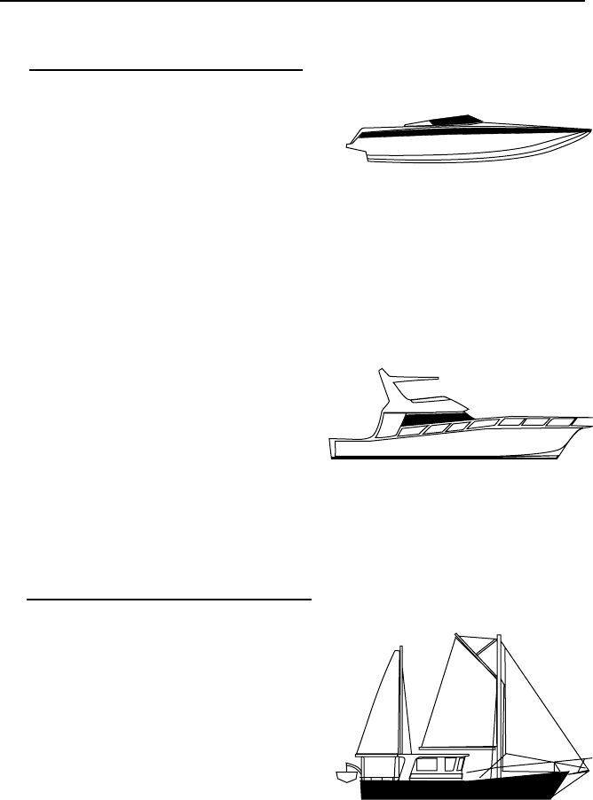
2.3 Finding the sweetspot
Motor Yachts
If the boat is a Fly bridge cruiser,
installing the console by the steer-
ing station on the fly bridge will
provide the best coverage of the
decks fore and aft. You may need
to experiment with positions to get
the best coverage of crew below
in the saloon. Even though it is
unlikely that anyone can fall over-
board from inside the saloon, it will
be more convenient for your crew
to not have to worry about taking
Pendants off when going below.
For all other Motor cursers, the
steering station usually has a good
view of the decks and is in exactly
the right place if a MOB track back
is needed. In all cases use the
bracket mount to keep the unit
clear of other dash board mounted
gear.
If possible, the best position can
often mounted on the wheel house
roof. In this case reverse the
bracket.
Sailing Yachts
Yachts with a “Dog House” or
Wheel house.
Just like the Motor yachts, mount
the Console as high as possible in
front of the steering station. Use
the bracket if possible and keep
the Console clear of other metal
instruments and the compass.

MOBiLert CREWSAFE 7000 SERIES 11
Centre and Aft cockpit boats.
The installation location is a little more critical par-
ticularly if the boat is 40 feet or longer. The chal-
lenge here is to get the Console as high as possible
but protect it from physical damage.
Mounting it on the steering binnacle will provide
good coverage and if it is high enough, no prob-
lems right up to the bow.
If you have a dodger and it is possible to mount
it above the companion way then this works re-
ally well. Good results also come from mounting
into the “Garage” above the companionway. Use
the Bulkhead Kit supplied and mount it as far away
from the other instruments in the garage as pos-
sible.
If a location on the deck above the companionway
is not an option then the next best place is beside
the companionway and as high as possible. Use the
bulkhead mount to keep it flat against the cabin
and away from your other instruments. If neces-
sary move an existing Log or Wind instrument
down to give the Console the highest position.
Wherever you put the Console make sure that it is
clear of halyards and sheets. We have built it tough
but it won’t be able to anchor 2000 Sq feet of spin-
naker.
Mounting it in the foot well of the cockpit may work
for small boats and cockpit crew but you are likely
to get false alarms if you have people working on
the foredeck. Test the unit first by putting it in the
chosen location and make sure that you have a re-
liable link to the Pendants at the extremities of the
boat. Only if all is OK start drilling holes.
Mounting below decks.
As mentioned, the radio waves sent by the Pendants do have some
ability to penetrate Fiberglass and wood. It is possible to mount the
Console below decks and get reliable coverage. Pick a location that is
away from metal like fridges and SSB radios and is in as much clear
air as possible.
Remember, if you do get a MOB Emergency you will need to find a
way to relay the track-back information to the helmsperson.

2.4 Testing for reliability
BEFORE YOU DRILL ANY HOLES…
Go through this procedure. It’s quick and may save some heart-
ache and filler.
Setup:
1. Make sure that the Pendants are charged and operating.
2. Temporarily locate the Charger in the area you intend to
permanently mount it. (See the section on installing the
charger)
3. Use tape (double sided), Blue Tack or a volunteer to locate
the Console in the place you have figured out is the best.
4. Temporarily connect power to the Red and Black wires of
the Console Power cable. (Use a cigarette lighter adapter or
even 12Volts worth of torch batteries)
5. Plug in the power cable (Don’t worry about hooking up the
GPS yet).
6. Switch the Console on and wait until it changes to the Pen
dant Status screen.
7. Attach a Pendant to the Belt Clip of some volunteers.
8. Leave one Pendant in the Charger.
Procedure:
Making sure that the Pendants can be read from the Charger
Identify the Pendant that is in the Charger.
Using the signal strength meter (Series of vertical bars beside the Pen-
dant Status) make sure that you get 4 bars showing.
Confirm that the Pendant that is in the Charger is showing “Charging” on
the Console. Take it out and confirm that it changes to “Safe” and put it
back as see that the Console can read it as “Charging” again.
If that bit is OK then proceed.
Otherwise, as a first option, try and find a better place for the charger. As
a last resort, relocate the Console.

MOBiLert CREWSAFE 7000 SERIES 13
Making sure that that the Pendants can be read from all over the boat.
Ask your volunteers to go to all of their usual places and stop. Looking
at the display check the signal strength indicators (vertical Bars) and
look for any Pendants that drop from 4 bars to 3 or more. If after about
10 seconds all 4 bars on every Pendant are showing then move onto the
next test.
For the second test, ask the volunteers to move about the boat very
slowly. Keep your eyes glued to the Console and look for any missing
bars. The reason for the slow movement is that a “dead spot” might only
be a yard wide and the system needs a few seconds to respond. Make
sure that you cover extremes like the pulpit and crouching down at the
anchor well.
If you don’t get any dropouts then your location is good. As a final test,
send a volunteer below decks. Make sure that they can at least get to the
Charger unit without any losses of signal strength. Try other areas below
decks to see what is possible. An engine room lined with lead based insu-
lation is always going to be a big ask, so don’t worry if this set off a MOB
alarm.
MOBiLert CREWSAFE 7000 SERIES 15
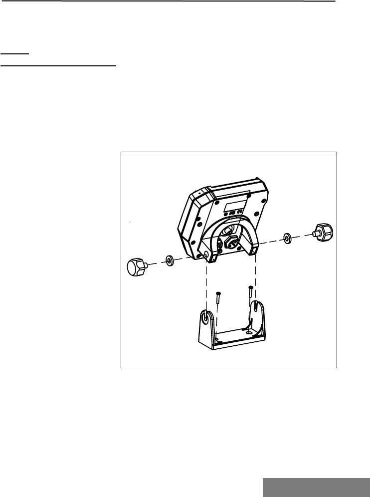
2.51
Bracket Mounting
The bracket needs to
be mounted on a flat
surface in a position that
can be seen by the helm.
Check that you have
enough clearance behind
the unit to mount the
connector(s).
The Console can be tilted
but not rotated so make
sure that you can look as
squarely on as possible.
Use the two self tapping
screws to mount into
wood. Self tapers can
also be used on fiber-
glass but metal thread
screws and nuts are a
better option. Either way,
if it is a wet area then
seal the holes with a
good quality marine seal-
ant before mounting the
bracket.
Slip the two neoprene
washers onto the studs
of the thumbscrews.
Thread the two thumb-
screws partly into the
console and slide the unit
into the bracket. Once
seated in the bracket,
adjust the angle and
tighten the thumbscrews.
2.50 Mechanical considerations
Unlike a GPS or fish finder, you don’t have to look at the screen all of the
time. MOBi-lert will tell you when you need to look at it.
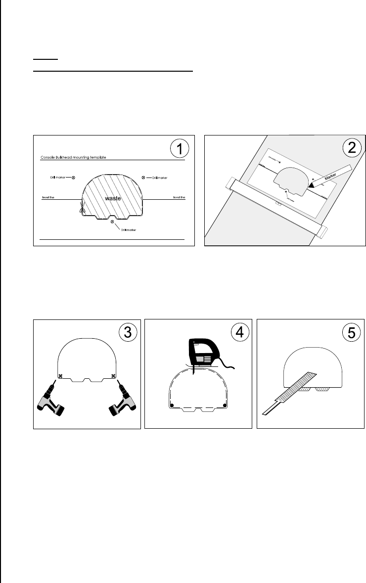
2.52
Bulkhead Mounting
Once you have found the “sweet spot” using
the procedure outlined above, find a location
that is flat for at least 150mm x 150mm.
Check that you have about 60mm of space
behind
the bulkhead for cable clearance. If you need
to confirm the location from the inside then
drill a small hole (1/8th inch) in the centre
of the proposed location and check that all is
clear behind.
1. Find the mounting template supplied at
the rear of this manual and remove from text.
Using a scissors carefully cutout the waste sec-
tion from the template.
2. Use the level line on the template to get
the template horizontal. Use some tape to
hold the template in place and carefully draw
around the inside of the template. Keep this
template for step 8
3. In each of the bottom
corners drill a ½ inch hole.
4. Using a jig saw or some-
thing similar, cut out the
centre section. It will prob-
ably be easier to cut straight
across the bottom Take a
lot of care with the cutting.
Clearances are tight along the
base of the cutout.
5. Use a file to remove mate-
rial from the two notches
at the bottom. As you are
cutting and filing, continue to
check the fit by offering up
the Console to the hole.
MOBiLert CREWSAFE 7000 SERIES 17
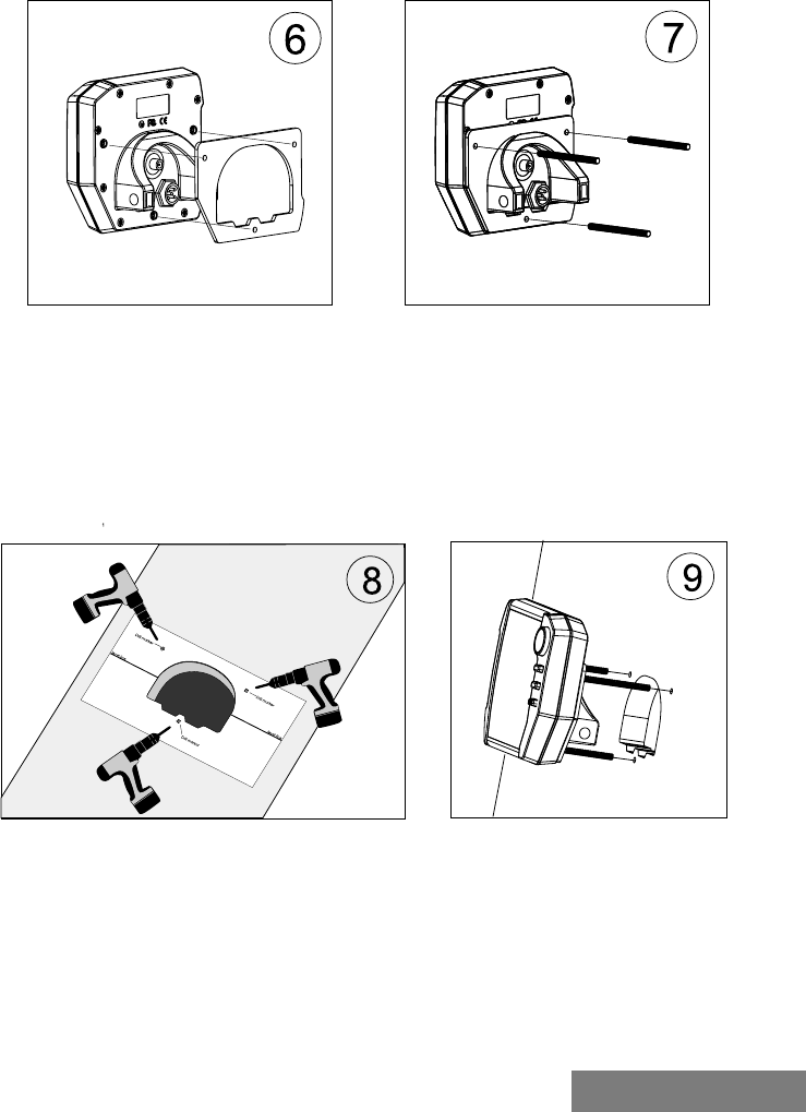
6. Find the foam sealing gasket and remove
the adhesive backing. Lay the console face
down on a bench. Apply the gasket sticky
side down onto the back of the console. Take
care with this job as the adhesive is a high
quality and won’t be too easy to re apply.
7. Once the gasket is on, thread in the 3
studs.
8. Offer the template up to the mounting
surface and temporarily affix, ensur-
ing the hole in the template and the
hole in the mounting surface align with
no obstructions. If all is OK then drill
the mounting holes as marked on the
template.
9. Offer the Console up to the hole and
check that it fits nicely without catching on
any sides. You should feel a bit of give as the
gasket compresses.
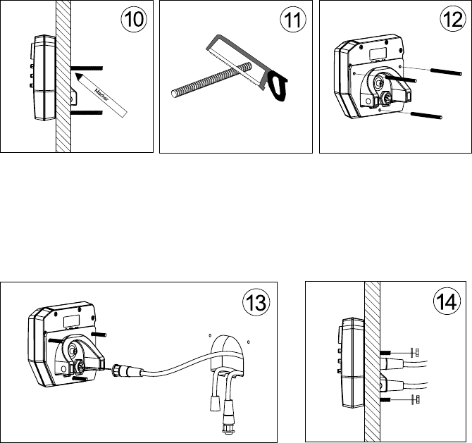
10. Mark the studs where
they exit the inside of the
bulkhead.
11. Remove the studs from
the console, add about 15mm
for the nut and washer and
cut off the excess.
12. Re-apply the thread to
the console.
13. Feed the cable(s) through hole and plug
them in. Make sure that the locking ring on
the connectors is seated home. (You should
feel a solid CLICK)
Switch on the system and make sure that the
display appears.
If you are using a separate GPS, confirm that
the GPS is connected properly by checking
for on screen warnings.
14. Place the Console into the hole and fit
the brass washers and M4 nuts to the studs.
Tighten these until they are firm and slightly
compress the gasket. If the mounting surface
is curved then you will not be able to seal by
applying extra tension. (Make up a spacer to
compensate for the curve)
DO NOT over tighten the nuts.
The brass inserts pressed into the plastic case
will break out and possibly fracture the case.
This may cause the Console to leak.

MOBiLert CREWSAFE 7000 SERIES 19
2.60 Electrical considerations
The MOB-ilert Console has two very sensitive receivers. Some care is re-
quired with the cabling to make sure that stray radio signals (noise) does
not get into the system and swamp the Pendant transmissions.
2.61Connection to essential services power
Some vessels (either by law or by choice) have a second battery dedi-
cated to the ships radios. The principal behind this is that in the event of
the main ships batteries becoming discharged or flooded, the ship can
still use her radios to call for help.
These radio batteries are often sealed “Gel Cell” types and placed high
above the waterline. If you do not already have this system it may be
worth considering installing it.
If you do have this type of system and there are no regulations prohib-
iting other equipment being connected to the essential service battery
then this is the ideal place to connect MOB ilert.
In the event of a serious event where the boat loses crew and power, the
essential services battery will allow the remaining crew to issue a radio
MAYDAY and be able to report the MOB position.
In addition, keeping MOB-ilert powered up keeps the track back active
for crew recovery.
2.62 Connection to standard ships power
If a second battery is not an option then cable the Console up to the
ships fuse or switch panel. A separate switch is not necessary as the
Console has its own power switch. A separate fuse or circuit breaker
is necessary to protect the ships power circuit. If you are connecting
directly to the battery include a 1 amp inline fuse holder. (Use a marine
grade part available from most marine retailers).

SECTION TWO
2.63 Keeping the cables out of trouble
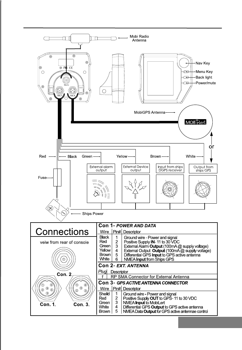
Termination
The Console power / data cable is a multi purpose cable designed to
do several things at once. If you are using the MOBi-lert GPS then the
Power cable will only need to be connected to the ships power and
the remote Alarm. A connection to the ships GPS as well will require
all three terminations. If you are planning to use more than just the
power and external alarm wires it may be worth considering using a
water resistant junction box. (These are usually available from Marine
equipment retailers).
Using a junction box you can split the common earth lead to service
the Console power, remote Alarm and also the ships GPS feed.
Either way, any wire to wire splices should be soldered and sealed
with silicon, Heat shrink tubing or self amalgamating tape. If possible,
solder automotive crimp connectors if these are used for any part of
the installation.
Routing the cables.
The digital signals sent by GPS are usually at low levels so it is im-
portant to make sure that the power / data cable does not pick up
interference (noise) from other systems.
In addition, the noise from some devices can jump across the internal
protection circuitry and interfere with the sensitive receiver circuits in
the Console.
Where possible, keep the Console power / data cable away from all
these devices:
Radio power / antennas
Engine ignition
Engine tachometer
Alternator feeds
Fish finders’ power and transducer cables.
Crossing noisy wires at right angles reduces a lot of problems other-
wise a separation of about 10cm is usually good enough.
Before lacing the cabling into the boat, temporally use tape to hold
the Power / Data cable in location and turn all the other systems on.
Satisfy yourself that MOBi-lert works 100%.
If all is good then complete the installation by securing the cables with
“P” clips and wire ties.

MOBiLert CREWSAFE 7000 SERIES 21
2.64 Connection of the External Alarm
Your MOBi-Lert kit contains one external piezo alarm.
It is essential that this alarm is connected into the system.
The console has an internal alarm but due to the complete waterproof-
ing of the case the noise it produces will not be enough to attract atten-
tion outside a few meters.
The external alarm needs to be mounted in a dry area and a place that
can be heard from the steering station. Try it out before drilling holes.
Once the desired location has been found then complete the installation
by securing the cables with “P” clips, self-adhesive clips and wire ties.

2.7 How the charger works
The charger is a microprocessor controlled system that stores, manages
and charges up to 6 pendants at one time.
It uses electromagnetic fields to inductively charge the pendants and in
this way avoids problems associated with metal contacts.
Signals sent by the charger are used to manage the pendants. The
charger is able to put the pendants to sleep and wake them up again.
The charger has only two power wires and no switches.
The LED indicator on the top of the unit will indicate the presence of
adequate power and when a pendant shutdown is taking place.
2.8 Finding the best spot
MOBi-Lert will only protect your crew if they are wearing the pendants.
Therefore it is really important that the pendants are kept fully charged
and are easy to get to during normal boat operations.
The first considerations are to make sure that power is available and
that charging pendants are within reliable radio range of the console.
The second consideration is for ease of use.
A location inside the cabin and near the main companionway is ideal.
In this position people can clip on a pendant before stepping out into
exposed areas. Mounting the charger in a place that can be easily seen
also has advantages as the Capitan can visually check to see if enough
pendants have been taken to cover the topside crew.
The pendant LEDs are pretty bright so that they can be seen in sunlight
and consequently may be bright enough to disturb sleeping crew so a
position that is not in direct view of the sleeping areas is desirable.
MOBiLert CREWSAFE 7000 SERIES 23
2.9 Testing for reliability
Once you have picked a spot that looks like it’s a good fit, temporarily
locate the charger in this position and install the pendants.
Power up the charger and make sure that the Console can reliability
pick up all of the pendants.
(See section 2 for further details on commissioning the system.)
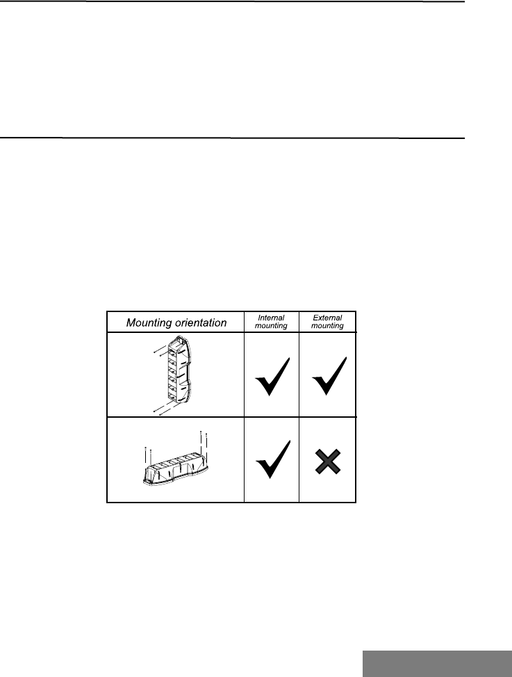
2.10 Mechanical considerations
Mounting on a Vertical surface
The charger is designed to be mounted onto a vertical surface like a
bulkhead or beside the companionway.
The reason is that it needs to be vertical is that if it raining or the seas
are running high, pendants and crew are likely to be wet. Placing a
wet pendant into the charger will not bother the equipment but if the
charger is mounted on a horizontal surface eventually the pendant bays
will fill with water and dirt.
The charger can be mounted vertically with the power cable facing up
or horizontally with the power cable coming from the left hand side.
Use the four 10G self tapping stainless steel screws to secure the
charger firmly to the boat. Bear in mind that in rough seas crew may
fall against it or use it to hold onto so make sure that it is really well
fastened.
Self tapers can also be used on fiberglass but metal thread screws and
nuts are a better option. Either way, if it is a wet area then seal the
holes with a good quality marine sealant before completing the job.

SECTION TWO
2.11 Electrical considerations
Running the cable
Routing the cable can be done externally from the top or left hand side
and secured to the boat with cable clips or P clips. Alternatively, the
charger has provision for the cable to be concealed by running it through
the bulkhead directly underneath where it exits the charger housing.
<<<<DIAGRAM>>>>
The cable needs to be terminated to a separately switched and fused
supply of ships power between 11 and 28 volts. The switch is very impor-
tant to the operation of the system so it needs to be readily accessible.
A fuse or circuit breaker of 1 amp will sufficient to protect the circuit.
Make sure that any wire to wire splices are soldered and sealed with sili-
con, heat shrink tubing or self amalgamating tape.
If possible, solder automotive crimp type connectors if these are used for
any part of the installation.

MOBiLert CREWSAFE 7000 SERIES 25
Pendants
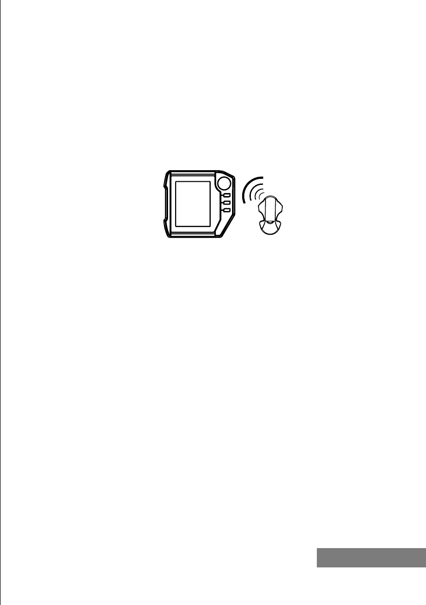
2.12 How the Pendants work
Each Pendant contains a microprocessor and a radio transmitter. During
manufacture the microprocessor is given a unique identification code.
The microprocessor’s job is to manage the battery charging, perform
diagnostics and transmit its unique code to the Console about once every
second.
At one end you will see a large black ferrite core. This is used to supply
power necessary to recharge the Nickel Metal Hydride batteries. At the
other end is the high gain helical antenna and status LED. (See section 3
on what the LED tells you)
2.13 Making it easy for crew to use them
All crew have to ware Pendants to be monitored.
Turning this task into a habit that all of your crew will do automatically
requires a bit of effort up front.
You will have to secure the Pendant clips to commonly used clothing and
equipment and make sure that your crew never leaves the cabin without
one.
2.14 Some options for wearing them
MOBi-Clip System
Each kit comes with two clips for every Pendant.
1. Lanyard clip is designed to be attached with lashing or webbing
to equipment or hung around the neck
2. Belt clip that has belt loop moulded for flat attachment to equip
ment or to be worn on the belt.
Using the supplied clips will produce the best results. The reasons are as
follows:
It allows for efficient radio transmission.
Attaching and removing is quick and positive
It is visible to the Captain and other crew
The Pendants LED can be monitored for battery status chang
es.
Alternatives to the Clip system
Keeping the Pendant in a pocket may work if the pocket is high like a
top pocket or shoulder pocket. If you put the Pendant in pants pocket
or inside your wet weather gear the RF signal tends to get soaked up by
your body mass. You may get false alarms when crouching down at the
anchor well for example.
Using a pouch (like supplied with rigging knives) will also work well as it
keeps a small gap between your body and the Pendant.
Lanyard Clip
The Lanyard clip is primarily for attachment via webbing or lashing for
equipment mounting.
Due to its lower profile it is also the simplest to wear using a neck lan-
yard.
WARNING: If you are wearing a pendant around the neck make sure that
the lanyard can separate easily in the event that it gets snagged.
Belt Clip
The Belt clip is the most versatile for universal attachment.
In addition to slipping it on a belt, it is wide enough to fit over most
safety webbing systems like those found on Personal Floatation Devices
(PFD) and safety harnesses.
For almost all applications it is best if the Clip guides face down when
you are wearing the equipment. The Pendant doesn’t care and the clip is
less likely to get caught on something.

MOBiLert CREWSAFE 7000 SERIES 27
Section Three
Using the system
3.10 Pendant Status LED
A multifunction LED in the front of the pendant will indicate to
the crew any one of 5 states.
These conditions are:
3.11 Short Green flash once every 2 seconds:
Battery good and the Pendant is transmitting
3.12 Short Red flash once every 2 seconds:
Battery Low and Pendant is transmitting – Pendant needs to be
recharged. (The crew will have up to 8 hours to recharge the
Pendant.)
3.13 Long Orange flash once every 5 seconds:
Indicates that the Pendant is in the Charger
Battery fully recharged and ready for use.
3.14 Red on hard:
Indicates that the Pendant is in the Charger
Recharging is in progress.
3.15 LED is off:
Two possible states
Pendant is in “sleep” mode and is not transmitting
Pendant batteries are completely flat
3.2 Charger Status LED
3.21 Long Green flash once every 3 seconds:
Charger is powered up and operating normally
3.22 Quick alternating Red and Green flash.
(Only lasts for about 5 seconds.)
Power has been removed from the Charger and the
Charger is putting any installed Pendants into sleep mode
3.23 LED is off:
Power to the charger is off.
MOBiLert CREWSAFE 7000 SERIES 29
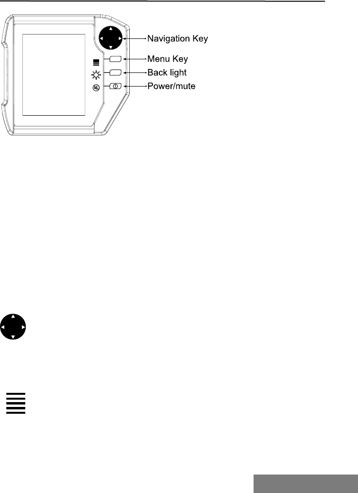
3.30 Controls on the Console Unit
The Console uses 7 buttons to control all features.
These buttons are from top to bottom.
4 Way menu navigation key
Menu access key
Screen backlight key
Power / Alarm mute key.
Of these 4 keys, the Power / Alarm mute key is the only one that has
dual functions.
3.31 What the buttons do
4 Way menu navigation key
The Navigation button allows you to move through the menu items.
Each menu page will have arrow instructions to help you find your way.
Menu access key
The Menu key will take you directly into the systems menus screens.
Once in the menus systems, continually pressing this key will take you
back to the main menu.
(More on the Menu’s later.)
Screen backlight key
Pressing this key will adjust the level of the screen backlight. It oper-
ates in a continuous loop from dimest to brightest and around again.
Power / Alarm mute key
Pressing and holding this key for one second will power the Console up.
When powered up, pressing this key again will bring up the Power Off
menu.
In the event of an active alarm, pressing this key will silence the continu-
ous alarm and put the alarm into an active reminder state.
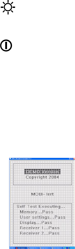
3.32 Powering up the display
Press and holding the power key for one second and the Console will
power up.
The first screen that you see is the BOOT LOADER START-UP screen
showing the software revision information.
A few seconds later the Console will automatically switch to its internal
diagnostic screen and run a series of self tests.
Assuming all goes well with
these tests, the system will
automatically switch to the
Pendant Status Screen.
MOBiLert CREWSAFE 7000 SERIES 31
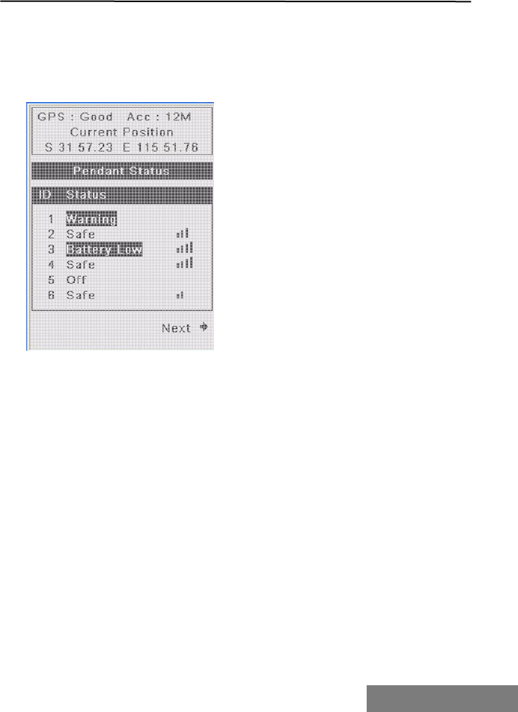
3.4 Normal Operation – Pendant Status Screen
Providing you GPS is connected and your pendants are in range and
not asleep, your Pendant Status Screen should look something like
this.
The top three lines
show information from
systems GPS.
Lower down is the
Pendant Status list.
This screen shows
a list of Pendants
that have been
programmed into the
system.
Pendant Status list
show 3 columns of
information:
Pendant ID
Column one is the Pendant I.D. This displays the number assigned to
each of the configured Pendants. This number is user assigned and
may not correspond with the Pendant Serial number.
Pendant Status
The Pendant Status column tells you what the Pendants are doing.
Pendant Signal
The last Column represents the signal strength and is a visual indicator
of the quality of the link to the Pendant.
In the same way as a Mobile Phone will display signal strength, the
more bars that you see displayed the better the link.
When a Pendant is in a bad location and the Console is losing contact,
these bars will start to drop. If they disappear altogether the Console
will display WARNING, and then in a few seconds, a full MOB alarm.
SECTION THREE
Possible conditions are:
Safe:
This indicates that the Pendant has good battery level, is operating
properly and is in range of the Console.
WARNING:
WARNING indicates that the Console has lost contact with a Pendant for
3 seconds and a provisional GPS position has been logged.
After this point the Pendant will either return to Safe or Battery Low if
the Console receives a further transmission OR go into full MOB alarm if
nothing further is heard.
Battery Low:
This indicates that the Pendant has low battery level, is operating
properly and is in range of the receiver. A battery will give the crew
member about 6 hours to swap Pendants and recharge the flat one. Any
Battery Low indicators will be highlighted by a flashing inverse video
entry. If a Battery Low Pendant gets out of range, a full MOB alarm is
issued.
Charging:
Pendant is no longer active and is in the MOB i-lert Charger being
recharged.
Off:
This means that the Pendant has not been registered as active and is out
of range or has been shut down.
NOTE: When the Console is switched on it will listen for all of the
Pendants registered in its memory.
If it can hear them it will display on the screen one of the first three
Status conditions described above.
If it can’t hear them it will report them as OFF.
If a Pendant is listed as Safe or Battery Low and loses contact, a full MOB
alarm is raised.
If a Pendant is listed as Charging (In the Charger) and loses contact, the
Console assumes that the Pendant has been put to sleep and no alarm is
raised.
.
MOBiLert CREWSAFE 7000 SERIES 33
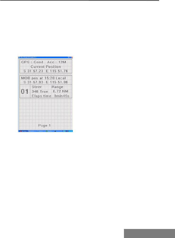
The top three lines show
information from systems
GPS.
It shows the ships current
position.
The next block of
information is MOB data.
First line displays the exact
time and GPS coordinates
of the event. This
information is vital to SAR
authorities.
3.5 MOB screen
If an active Pendant loses contact with the Console, a full MOB alarm is
issued.
A pulsed alarm will be emitted from the Console and the external alarm.
The Console will automatically switch to the MOB screen.
The user will get the following information:
Next block of information is the missing Pendant ID followed by the
bearing and range back to the MOB location.
The bearing and range information will give the helmsman instructions
on how to steer back to the location of the MOB.
The information is calculated from the point where the MOB occurred.
It will constantly update to provide the Helm with updated bearing and
range data.
If any further Pendants go missing, separate entries for each will appear
in order on the MOB screen.
If there are more MOB entries than can fit on the display the operator
will be prompted with a Next symbol. Pressing the Navigation key will
bring up the next list of entries.
Once a Pendant is back in range, the MOB entry for it will be
automatically cancelled. Once all of the MOB entries are back in range
the alarms will stop and the screen will switch back to the normal
“Pendant Status Screen”

MOBiLert CREWSAFE 7000 SERIES 35
3.6 Recharging the Pendants
At the end of the day or when “Battery Low” is indicated by either the
Pendant or Console, the crew will normally return his or her Pendant to
the Charger.
This is done not only to recharge the Pendant but also as a convenient
storage location.
If the Charger is powered up, installing the Pendant will cause the Pen-
dant LED to change from flashing (Green or Red) to solid RED.
This indicates that the Pendant is in fast charge mode.
The Pendant will stay in this mode for between 45 minutes for a fully
charged unit and 15 Hours for one with completely flat batteries.
After maximum charge has bee achieved the Pendant will display a long
Orange flash once every 5 seconds to indicate that it is fully charged and
in a trickle charge state.
Whenever the Pendant is in a powered up Charger, the Console will list
the Pendant as “Charging”.
Switching the Pendants off and on.
Putting the Pendants to sleep.
The sleep state is where the Pendant is monitoring its battery but is not
transmitting.
Reasons you may want to do this include,
Finished sailing for the day.
Taking the Pendants home or transporting them somewhere.
(Particularly important for air travel.)
Need to remove them from the airwaves when someone close by
is trying to register a different set of Pendants.
To do this, all that is required is to install them into a powered up charg-
er and remove the power.
The Charger LED will flash quickly between red and green and tell the
Pendants to go to sleep.
You will see that all of the Pendant LED’s will turn off.
The Console will show that Pendant as OFF.
Waking the Pendants up.
It’s easy; just insert a sleeping Pendant into a powered up Charger.
The Pendants LED will glow RED and the Console will report that the Pen-
dant is charging.

3.7 switching the pendants on and off
Putting the Pendants to sleep.
The sleep state is where the Pendant is monitoring its battery but is not
transmitting.
Reasons you may want to do this include,
Finished sailing for the day.
Taking the Pendants home or transporting them
somewhere. (Particularly important for air travel.)
Need to remove them from the airwaves when someone
close by is trying to register a different set of Pendants.
To do this, all that is required is to install them into a powered up charg-
er and remove the power.
The Charger LED will flash quickly between red and green and tell the
Pendants to go to sleep.
You will see that all of the Pendant LED’s will turn off.
The Console will show that Pendant as OFF.
Waking the Pendants up.
It’s easy; just insert a sleeping Pendant into a powered up Charger.
The Pendants LED will glow RED and the Console will report that the Pen-
dant is charging.
MOBiLert CREWSAFE 7000 SERIES 37
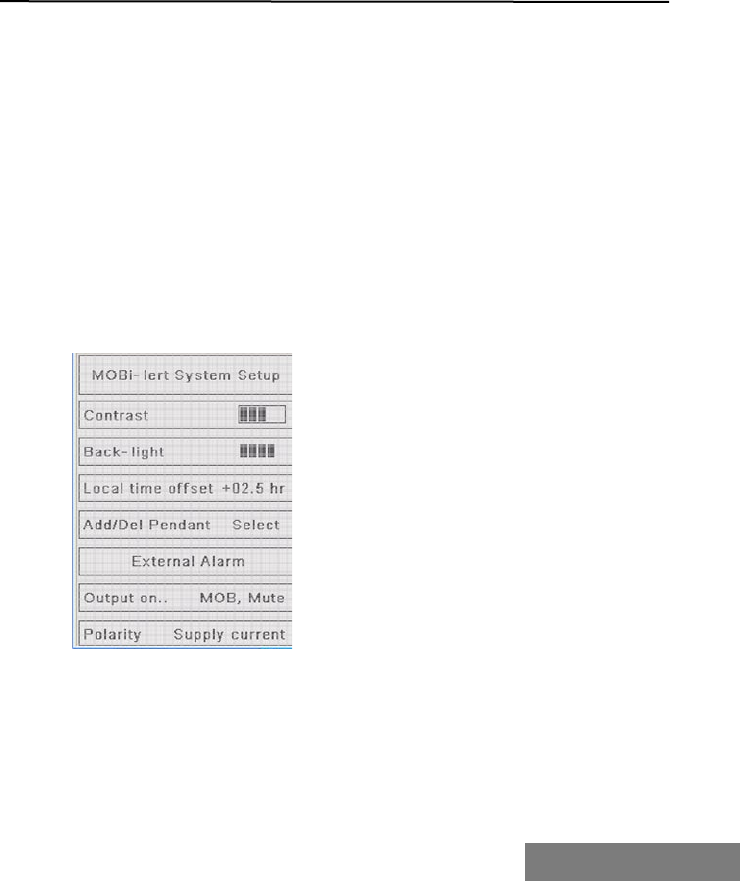
The following options are
available.
1. Contrast
2. Back-Light
3. Local time offset
4. Add/Del Pendant
5. External Alarm
Section Four
Making changes to MOBiLert
4.1 Changing the screen settings
Hitting the Menu key will bring up the following Menu choices:
Pendant Status
System Setup
Event Log
Selecting Pendant Status takes you back to the Pendant Status Screen
described above.
System Setup
The System setup screen allows you to configure MOBi-lert to suit your
application and preferences.
Looking at each inturn.
4.11 Contrast
This setting will adjust the contrast of the LCD display.
Use the down arrow on the Nav Key to select the setting (You will see a
square box drawn around the level bars) □.
Push the Nav key left arrow to increase the setting and the right arrow to
decrease.

4.12 Back-Light
This setting will adjust the level of the screen backlight.
Use the down arrow on the Nav Key to select the setting (You will see a
square box drawn around the level bars) □.
Push the Nav key left arrow to increase the setting and the right arrow
to decrease.
Note. This function is also available from the □ Key on the front panel.
4.2 Local time offset
The MOBi-lert system has no internal clock and derives its time and
date from the connected GPS.
The GPS delivers time information as Coordinated Universal Time
(UTC). The Local time offset allows you to put in a value to correct the
on-screen time from UTC to local.
This local time value is determined by the operator and is not updated
automatically. If you change time zones you will need to manually ad-
just this setting.
Note: The information stored in the Event Log is only recorded as UTC.
Therefore if the local setting is wrong or the rescue authorities request
the time of the event in UTC this information is available in the Event
Log.

MOBiLert CREWSAFE 7000 SERIES 39
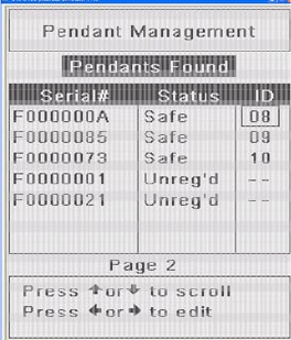
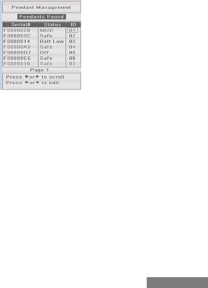
4.3 Add/Del Pendant
The fourth option on the System Setup.
From here you can Add, Delete or change the displayed ID of a Pendant.
Information is presented in three columns marked:
Serial#, Status and ID
The serial Number column displays the full serial number of the Pen-
dants that the Console can hear. The serial number is in Hexadecimal so
you will see letters as well as numbers. The serial numbers cannot be
changed.
The next column is the Status of the Pendant.
The Pendant can be reported as six possible states:
Safe Pendant is registered and in range – Battery
good
Battery Low Pendant is registered and in range – Battery Low
Charging Pendant is registered and in range and charging
MOB Pendant is registered but out of range
OFF Pendant is registered but its state has changed
from Charging to out of range
Unreg’d Pendant is not registered but can be heard by the
system
The Pendants that the console has registered in its database is displayed
on the top.
Below these entries are the Unreg’d Pendants that the Console can hear.
Use the up down arrow keys on the Navigation key to select a Pendant
to change.
Use the Left / Right arrow keys to prepare the field for changing. The
entry will change into inverse video.
Use the up/down keys to scroll
through the available numbers.
You will only be able to select
a number if it has not already
been assigned.
Once the Pendant is set the way
you want it, hit right arrow to
save the setting.
In addition to setting the Pen-
dants displayed number you
can also permanently delete a
Pendant from the system.
The reasons that you might want to do this include:
If a Pendant has been lost or damaged
If a Pendant belonged to temporary crew who are leaving the
boat.
There is no need to delete pendants if you are not using them or you
have left them at home.
Providing Pendants are shut down using the charger then the system
knows that they are off.
The display will still show their status but it will be Off.
Note: If a Pendant was MOB when the system is shut down the sys-
tem will remember this status when it is powered back on.
To delete a pendant scroll through the available numbers until you get
to Del? Hit the right arrow key to activate
You will be asked to confirm.
Delete Pendant. Are you sure? YES/NO
If you hit any key other than up arrow to select yes and then right ar-
row to confirm then the system will cancel the delete operation.
WARNING:
BE ABSOLUTELY SURE THAT THE PENDANT THAT YOU ARE DELETING
IS NOT BEING USED BY ANYONE.
MOBiLert CREWSAFE 7000 SERIES 41
If you delete a Pendant that some-
one is wearing then that person is
no longer protected.
MOBiLert cannot tell you if that
crew member is lost overboard.
To exit back to the main menu, hit
the menu key again.
External Alarm
In addition to the External Alarm
supplied with the kit, the systems
provides for a second external
output. This output is a relay that
will switch the ships power out at
100mA.
You could possibly use this output to do the following:
Sound another external alarm. Inside the cabin?
Activate a MOB function on your self steering
Activate an engine shutdown
Release a danbuoy or some other safety device.
Generate an automated distress call on a VHF radio etc..
Configuring the remote alarm
You have two settings available to customise the output of this device.
Output on: This setting defines what event will trigger the External
Alarm.
Options are:
1. Disabled
2. MOB Only
Alarm is triggered only on a MOB event
3. MOB, Mute
Alarm is triggered by a MOB and cannot be muted
4. Batt low
Alarm is triggered by any battery low conditions reported by an
active Pendant.
5. Bad GPS
Alarm is triggered by a loss of GPS information
The next setting is Polarity
his setting defines the output of the port when it is triggered.
Settings are:
1. Switch on
Ships voltage is normally off and is switched on when triggered.
2. Switch off
Ships voltage is normally on and is switched off when triggered.

MOBiLert CREWSAFE 7000 SERIES 43
Section Five
Appendices
5.1 Console bulkhead mounting template
5.2 Console connection diagram
5.3 Charger connection diagram
5.4 MFP 0012 Console - Technical Specifications
5.5 MFP 0013 Charger Technical Specifications
5.6MFP 0015 Pendant Technical Specifications
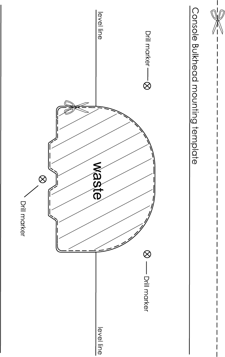
5.1
MOBiLert CREWSAFE 7000 SERIES 45
5.2 Console connection diagram
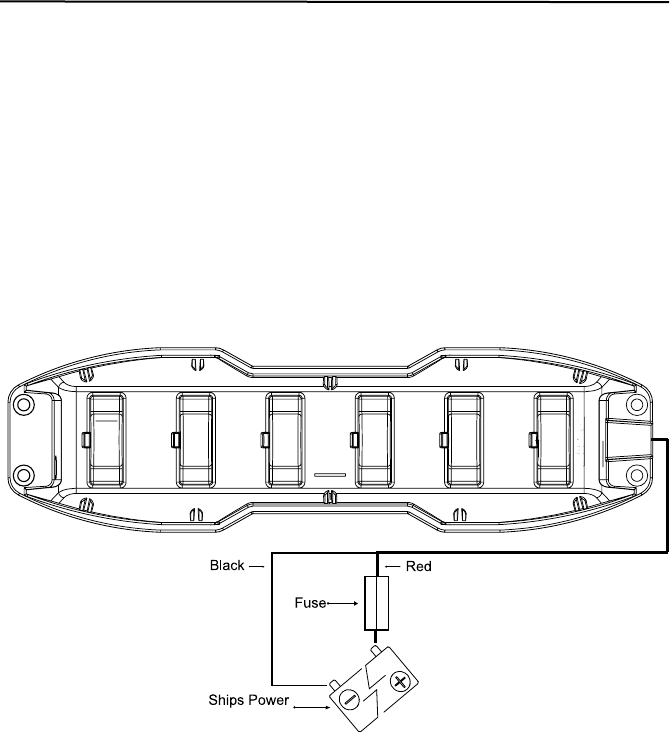
5.3 Charger connection diagram

MOBiLert CREWSAFE 7000 SERIES 47

5.4 MFP 0012 Console - Technical Specifications
Power supply: 11-30 V DC
Typical power consumption: 70 mA (at 12 V DC) Max (With backlight on full)
Screen 320 x 240 pixels with 16 grey scales
Backlight settings 5 Levels plus automatic on event
Frequency of operation 434MHz FSK (Dual channel)
Antennas Internal ceramic patch, External dipole (Plus
other options)
Audible response Key press, Low Pendant battery, Alarm mute,
MOB
Pendant condition reporting Safe, Charging, Low battery, Link Warning,
MOB, Off
Event Log Records Waypoint, Pendant event, Time and
Date - 450 Events - FIFO
Configuration storage EEPROM Non volatile
Output: 1 - External Alarm 100mA at supply voltage into supplied
Waterproof Piezo alarm
Output: 2 - Secondary output 100mA at supply voltage
Output: NMEA NMEA 0183 (ver 2) GPWPL
Input NMEA from GPS NMEA 0183 (ver 2) GPRMC, PGRME,
Input NMEA from Differential Receiver NMEA 0183 (ver 2) Signal fed directly to GPS
Operating temperature: 0 to 50°C (32 to 122°F)
Dimensions 120 x 115 x 60 (without bracket)
Weight (without cable): 310 g (13 oz)
Case: UV stabilised ABS with polycarbonate screen
Mounting Options Surface mount with bracket or flush mount with
gasket kit
Environment: IP67.
5.5 MFP 0013 Charger Technical Specifications
Power supply: 11-30 V DC
Typical power consumption: 140 mA (at 12 V DC)
LED Status Slow green flash, Quick green/red flash 5
seconds, Quick green/red flash Continuous
Charge current – Boost Charge 14mA
Boost Charge Time (Max) 15 Hours
Charge current – Trickle Charge 3mA
Trickle Charge Time Continuous
Operating temperature: 0 to 50°C (32 to 122°F)
Dimensions 333 x 94 x 70
Weight (with cable): 1000 g (35 oz)
Case: UV stabilised ABS
Mounting Options Surface mount
Environment: IP66.

MOBiLert CREWSAFE 7000 SERIES 49
5.6 MFP 0015 Pendant Technical Specifications
Power supply: 3.6v Nominal
Typical power consumption: <1 mA
LED Status Off, Quick flash green, Quick flash red, Slow flash
orange, red on hard
Batteries 3 x 1.2v 100mAH NiMH button cells
Operating temperature: 0 to 60°C (32 to 140°F)
Battery life – Battery Full 48 Hrs Minimum (- De rating for temperature
extremes)
Battery life – Battery Indicating
Low Typically 8 Hrs (Temperature dependant)
RF Transmission Frequency Chan A – 433.93MHz, Chan B – 434.33 MHz,
RF Transmission Power < 1mW FSK
Weight: 46 g (1.6 oz)
Case: Ultrasonically sealed Polycarbonate.
Environment: IP68.

EC Declaration of Conformity
In accordance with EN 45014:1998
We MOBi-larm
Of 768 Canning Highway, APPLECROSS WA 6153
Declare that:
Equipment Mobilert Crewsafe 7200 & 7600 Man
Overboard Monitoring Systems
Model name / number MOA 0010 & MOA 0011
Serial number 5 MOA 0010 - 00050 to MOA 0010 - 99999
MOA 0011 - 00050 to MOA 0011 - 99999
In accordance with the following Directives:
73 / 23 EEC The Low Voltage Directive
89 / 336 / EEC The Electromagnetic Compatibility Directive
and its amending directives
98 / 37 EC The Machinery Directive
and its amending directives
99 / 5 / EC The Radio and Telecommunications Terminal
equipment directive
has been designed and manufactured to the following specifications:
ETSI EN 300 220 -1 Electromagnetic compatibility & radio spectrum matters
(ERM);
Short range services (SRD); 25MHz to 1000 MHz with
power levels ranging up to 500mw Part 1.
ETSI EN 300 220- 3 Electromagnetic compatibility & radio spectrum matters
(ERM);
Short range services (SRD); 25MHz to 1000 MHz with
power levels ranging up to 500mw Part 3.
ETSI EN 301 489 – 1 Electromagnetic compatibility & radio spectrum matters
(ERM);
Electromagnetic compatibility (EMC) standard for radio
equipment & services Part 1.
5.7 EC Declaration of conformity
MOBiLert CREWSAFE 7000 SERIES 51
ETSI EN 301 489 - 3 Electromagnetic compatibility & radio spectrum matters
(ERM);Electromagnetic compatibility (EMC) standard
for radio equipment & services Part 3.
ETSI EN 301 843 – 1 Electromagnetic compatibility & radio spectrum matters
(ERM); Electromagnetic compatibility (EMC) standard
for Marine radio equipment & services; Part 1.
EN 60950 Safety of Information Technology Equipment Including
Electrical Business Equipment.
EN 50364: 2001 Limitations of human exposure to electromagnetic fields
from devices operating in the frequency range 10Hz
to 10GHz, and in radio frequency identification (RFID)
and similar applications.
I hereby declare that the equipment named above has been designed to comply
with the relevant sections of the above referenced specifications. The unit complies
with all essential requirements of the Directives.
Signed by:
Name: Irwin Tollman
Address: 768 Canning Highway
APPLECROSS WA 6153
Position: Chief Financial Officer
Done at MOBILARM
768 Canning Highway
APPLECROSS, PERTH, WESTERN AUSTRALIA 6153
On Friday 30th day of July 2004
04