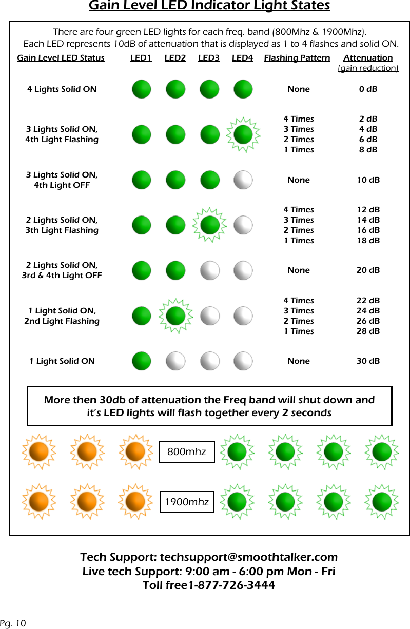
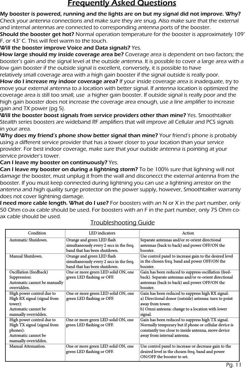
Mobile Communications BRB8191 Dual Band, Bi-Directional Wireless Booster User Manual

Mobile Communications Inc. Dual Band, Bi-Directional Wireless Booster Users Manual

Users Manual

®Stealth Series Dual Band Booster AmplifiersBRB819 Series User ManualCOTTAGESBUILDINGSHOMESBOATSRV’s & BUSES
®Stealth Series Dual Band Booster AmplifiersFeatures.....................................................................3Specifications...........................................................3Package contents....................................................4Optional setup/parts..............................................5Antenna and Booster Installation......................6Installation Illustrations..........................................7Control panel ...........................................................8LED lights - Outside signal level/RX power......8Gain level...................................................................9Manual gain control...............................................9LED lights - Gain level .........................................10Tech support..........................................................10Frequently asked questions..............................11Troubleshooting guide.......................................11Glossary of terms..................................................12FCC information....................................................12Warranty..............................................................12Table of ContentsPg. 2
FeaturesGain Level Indicator (LED)Pwr ON/OFF Switch & LEDOutside Signal Level (LED)Control Buttons for: Manual Gain - 2dB steps & LED Brightness LevelMaster Control SwitchSpecificationsFCC Approved For:CDMA, WCDMA, LTE, HSPA, GSM, GPRS, EDGEModel:GainOperating Frequencies:Max TX Power: CDMA/3G/4GConnector Type:Operating Temperature:Dimensions:(not including connectors)Weight:BRB819-5858 dBCellular/PCS29.33 dBmN-Female 50 ΩMCT-Male 50 ΩF-Female 75 Ω-32°C to +85°C-25°F to +185°F159x89x28.6 mm6.25x3.5x1.125 in0.45 kg/1.00 lbBRB819-6262 dBCellular/PCS29.33 dBmN-Female 50 ΩMCT-Male 50 ΩF-Female 75 Ω-32°C to +85°C-25°F to +185°F159x89x28.6 mm6.25x3.5x1.125 in0.45 kg/1.00 lbBRB819-6868 dBCellular/PCS29.33 dBmN-Female 50 ΩMCT-Male 50 ΩF-Female 75 Ω-32°C to +85°C-25°F to +185°F159x89x28.6 mm6.25x3.5x1.125 in0.45 kg/1.00 lbPg. 3
Package ContentsModels: BRB819-68XK/68NK Kit SeriesModels: BRB819-58XK/62XK/62NK Kit SeriesModels: BRB819-58X/62X,N,F/68X,N,F SeriesPackage Contains:Package Contains:Package Contains:BRB819 Series boosterAC/DC  120V wall power supplyTwo Smoothtalker directional antennasExtension Co-ax cableBRB819 Series boosterAC/DC  120V wall power supplyTwo Smoothtalker directional antennasBRB819 Series boosterAC/DC  120V wall power supplyPg. 4
Optional Setup with Line AmplifierConnect toIndoor AntennaConnect toOutdoor AntennaBST Series 3Watt Booster(Line amplifier for remote locations)Optional PartsOmni DirectionalAntennasCo-Ax Cables Antenna Pole Mount KitRF Splitter/Power Divider Co-Ax AdaptersPg. 5
Antenna and Booster Installationa) Location: There are three choices. fig. 2, 3, 4.The choice of donor antenna location depends on the signal strength at the donor antenna location. Use your phone to determine if signal at your chosen location is adequate. Better signal level at the donor antenna location equals larger indoor coverage area.b) Directional Donor Antenna: if using a directional donor antennasupplied in the kit (Part# SEMD1), point the antenna toward the desired tower. If the loca-tion of the desired tower is not known, initiate a phone call and use the signal indicator on your phone after the booster is operational, while turning the donor antenna, to determine optimum donor antenna direction for maximum signal strength.c) Omni-directional Donor Antenna: if using an omni-directional donor antenna, it is recommended that it is placed as far as possible from the inside anten-na, usually, ‘outside pole mount’ is recommended (Fig. 3). Use of omni-directional antennas will require substantial separation distance compared to directional antennas. Fig. 1Donor Antenna: (outdoor signal antenna)Distribution Antenna: (indoor signal antenna)Connection and Start Procedure:Amplifier/Booster Location:Install the repeater in a location that has proper ventilation, away from excessive heat and moisture.a) Location: There are three choices. fig. 2, 3, 4.The choice of donor antenna location depends on the area to be covered.b) Directional Distribution Antenna: it is recommended that directional antennasare oriented in a fashion that is back to back of each other Fig. 1c) Omni-directional Distribution Antenna: it is important that omni-directional antennas are separated as far apart as possible from each other. Use of omni-directional an-tennas will require substantial separation distance compared to directional antennas. Fig. 1d) Splitting Indoor Signal: it is possible to use more than one indoor antenna tocover areas that are separated by walls or floors by using antenna splitters or power dividers, however splitters have a level of signal loss (3dB) and the added cable run will also have signal loss, therefore the coverage area will be diminished. As a general rule, if outside signal is good, splitting signal to more than one distribution antenna results in reasonable coverage.If outside signal is poor or marginal, splitting signal to more than one distribution antenna results in decreased coverage for both distribution antennas.Use only genuine SmoothTalker splitters.  Contact your dealer or www.smoothtalker.comWARNING:Make sure all cables have a good connection and are connected to the correspondingantenna port on the Booster.DO NOT APPLY POWER or turn on the power switch on the Amplifier/Boosterbefore all cables and antennas are connected.Antenna connections must be snug and hand tight, ‘Do Not Use Pliers or Wrench’.Connect the cable from outdoor antenna to RF port (antenna connector) labeled “Outdoor Antenna”. Connect cable from indoor antenna to RF port labeled “Indoor Antenna”.Connect supplied AC/DC power supply to the amplifier and plug it into power source.Turn on the power switch on the Amplifier/Booster.Pg. 6
Omni directional antennas separation distance - FarDirectional antennas separation distance - CloseFig. 1Fig. 2Fig. 3Fig. 4Distribution Antenna(pointed indoors)Donor Antenna(pointed outdoors)BoosterOutside Signal Level/RX Power LED Indicator Light StatesPg. 7
Control Panel: Understanding the Control Panel and LED lightsOutside Signal Level/RX Power LED Indicator Light StatesGeneral: Mobile networks, phones and data devices operate in two frequency bands (800Mhz & 1900Mhz). The Stealth Booster will amplify signals in both bands if they are present. The band that the phone or cellular data device will transmit (TX) and receive (RX) on is determined by the cellular provider and cannot be chosen by the user. The booster LED lights  will indicate outside signal level and booster gain. The ‘Master Control’ button on the control panel will allow the user the option to increase gain, decrease gain or shut off one or both of the frequency bands.Outside Signal Level(Orange LED)Master ControlSwitchGain Level(Green LED)Control Buttons for: Manual Gain - 2dB stepsOutside Signal LED lights: three orange LED lights for each frequency band indicate out-side RX signal strength (base station power) being amplified by the booster and transmit-ted into the building (Receive Power). This indicator is affected by two things : the outside signal and attenuation that is applied by the user or the automatic controls of the booster. The highest level signal being displayed by the booster lights can belong to any service provider, not necessarily your service provider. To determine if your provider is the high signal provider, start a call and place your phone at or close to the location of the donor (outside) antenna and compare the phone signal bars to the LED indicator lights on the booster. Note: if attenuation (gain reduction) has been applied by the automatic controls of the booster or by the user, you may see low signal indication on the booster LED lights even though the true outside signal is strong.LED Light Brightness: the user can control the LED brightness of all LED lights by pushing the up or down arrows on the control panel.Outside Signal Level LED LED1 LED2 LED3 Flashing Signal Strength3 Lights Solid ON No ExcellentGoodFairFair to LowLowLow or NoneYesNoYesNoYes2 Lights Solid ON,3rd Light Flashing2 Lights Solid ON,3rd Light OFF1 Light Solid ON,2nd Light Flashing1 Light Solid ON,2nd & 3rd Lights OFF1 Light Flashing,2nd & 3rd Lights OFFPg. 8
Gain Level: Understanding the Control Panel and LED lightsManual Gain ControlGeneral: Four green LED lights for each frequency band will indicate the the level of amplifi-cation that is being applied by the Booster to the receive (RX) signal and transmit (TX) signal. Gain is applied to both RX and TX signals. Normally all four green LED will be solid on. If any green LED lights are flashing or off, it is an indication that gain has been reduced. There are four events that will cause the green LED lights to turn off or flash.1) Shutdown:a) Automatic shutdown will occur in one band or both bands if antennas are placed too close to each other and the ‘Automatic Oscillation (feedback) Suppression’ function cannot eliminate the oscillation. TX and RX gain will be turned off completely in the frequency band where oscil-lation cannot be suppressed.b) Manual shutdown can also be achieved in one or both frequency bands by the user.2) Oscillation (feedback) Suppression:The booster will automatically apply attenuation (reduce gain) to suppress oscillation (feed-back). This function is automatic and cannot be manually overridden.3) High Power Control:The booster will automatically apply attenuation (reduce gain) if RX or TX power is too high. This function is automatic and cannot be manually overridden.4) Manual Attenuation:Gain can be increased or decreased manually by the user in 2dB steps over a range of 30 dB for each frequency band, however, the user will not be able to reduce attenuation that has been applied by the automatic oscillation suppression function or by the automatic high powercontrol function in order to protect both, the cellular tower and the booster.The master control button has 3 functions which cycle every 3 times pressed as follows:1) 800mhz manual gain control Press once. The 3 orange LED lights for the 800 mhz band will flash together. Use up or down arrows to adjust gain in this frequency band as desired. Each push of the up or down button will adjust 2 dB of gain. Total manual adjustment range is 30 dB. Adding more than 30 dB of attenuation will shut down the frequency band. Quick shutdown of the frequency band can also be achieved by holding the down arrow. When the frequency band shuts off all of the orange and green  LED lights for that frequency band will flash every 2 seconds.2) 1900mhz manual gain control Press again. The 3 orange LED lights for the 1900 mhz band will flash together. Use up or down arrows to adjust gain in this frequency band if desired. Each push of the up pr down button will adjust 2 dB of gain. Total manual adjustment range is 30 dB. Adding more than 30 dB of attenuation will shut down the frequency band. Quick shutdown of the frequency band can also be achieved by holding the down arrow. When the frequency band shuts off all of the orange and green  LED lights for that frequency band will flash every 2 seconds.3) Manual gain LED display Press again to display the LED status of your inputed manual gain settings then power the booster OFF/ON for manual settings to take effect. Each time you cycle to this 3rd setting you will see your inputed manual gain settings displayed on the LEDs.Note: the booster will remember manual settings through power on and off conditions. If you want to return the booster to ‘Fully Automatic Mode’ you must go through step 1 and set the 800 MHz gain control to full gain (four green LED lights solid ON), then go through step 2 and set the 1900 MHz gain control to full gain (four green LED lights solid ON). Power the booster OFF and then ON for ‘fully automatic mode’ to take effect.Important:a) for manual settings to take effect, the booster must be powered OFF and then ON.b) manual settings cannot override the automatic functions of oscillation and high powercontrols. This means that if you are trying to set a gain level higher than the automatic control functions allow, the manual gain settings will be limited by the automatic control functions.Pg. 9
Gain Level LED Indicator Light StatesMore then 30db of attenuation the Freq band will shut down andit’s LED lights will flash together every 2 seconds800mhz1900mhzThere are four green LED lights for each freq. band (800Mhz & 1900Mhz). Each LED represents 10dB of attenuation that is displayed as 1 to 4 flashes and solid ON.Gain Level LED Status Flashing Pattern Attenuation (gain reduction)LED1 LED2 LED3 LED44 Lights Solid ON NoneNoneNoneNone4 Times3 Times2 Times1 Times4 Times3 Times2 Times1 Times4 Times3 Times2 Times1 Times2 dB4 dB6 dB8 dB12 dB14 dB16 dB18 dB22 dB24 dB26 dB28 dB0 dB10 dB20 dB30 dB3 Lights Solid ON,4th Light Flashing3 Lights Solid ON,4th Light OFF2 Lights Solid ON,3rd & 4th Light OFF2 Lights Solid ON,3th Light Flashing1 Light Solid ON,2nd Light Flashing1 Light Solid ONTech Support: techsupport@smoothtalker.comLive tech Support: 9:00 am - 6:00 pm Mon - FriToll free1-877-726-3444Pg. 10
Frequently Asked QuestionsMy booster is powered, running and the lights are on but my signal did not improve. Why?Check your antenna connections and make sure they are snug. Also make sure that the external and internal antennas are connected to corresponding antenna ports of the booster.Should the booster get hot? Normal operation temperature for the booster is approximately 109° F, or 43° C. This will feel warm to the touch.Will the booster improve Voice and Data signals? Yes.How large should my inside coverage area be? Coverage area is dependent on two factors; the booster’s gain and the signal level at the outside antenna. It is possible to cover a large area with a low gain booster if the outside signal is excellent, conversely, it is possible to haverelatively small coverage area with a high gain booster if the signal outside is really poor.How do I increase my indoor coverage area? If your inside coverage area is inadequate, try to move your external antenna to a location with better signal. If antenna location is optimized the coverage area is still too small, use  a higher gain booster. If outside signal is really poor and the high gain booster does not increase the coverage area enough, use a line amplifier to increase gain and TX power (pg 5).Will the booster boost signals from service providers other than mine? Yes. Smoothtalker Stealth series boosters are wideband RF amplifiers that will improve all Cellular and PCS signalsin your area.Why does my friend’s phone show better signal than mine? Your friend’s phone is probably using a different service provider that has a tower closer to your location than your serviceprovider. For best indoor coverage, make sure that your outside antenna is pointing at yourservice provider’s tower.Can I leave my booster on continuously? Yes.Can I leave my booster on during a lightning storm? To be 100% sure that lighning will not damage the booster, must unplug it from the wall and disconecct the external antenna from the booster. If you must keep connected during lightning you can use a lightning arrestor on the antenna and high quality surge protector on the power supply, however, Smoothtalker warranty does not cover lightning damage.I need more cable length. What do I use? For boosters with an N or X in the part number, only 50 Ohm co-ax cable should be used. For boosters with an F in the part number, only 75 Ohm co-ax cable should be used. Troubleshooting GuideConditionAutomatic Shutdown.Manual Shutdown.Oscillation (feedback) Suppression: Automatic cannot be manually overridden.Manual Attenuation. One or more green LED solid ON, one green LED ashing or OFF.Use control panel to increase or decrease gain to the desired level in the chosen freq. band and power ON/OFF the booster to set.High power control due to High RX signal (signal from tower): Automatic cannot be manually overridden.High power control due to High TX signal (signal from phones): Automatic cannot be manually overridden.Orange and green LED ash simultaneously every 2 secs in the freq. band that has been shutdown.Orange and green LED ashsimultaneously every 2 secs in the freq. band that has been shutdown.One or more green LED solid ON, one green LED ashing or OFF.One or more green LED solid ON, one green LED ashing or OFF.One or more green LED solid ON, one green LED ashing or OFF.Separate antennas and/or re-orient directional antennas (back to back) and power OFF/ON the booster.Use control panel to increase gain to the desired level in the chosen freq. band and power OFF/ON the booster.Gain has been reduced to suppress oscillation (feed-back). Separate antennas and/or re-orient directional antennas (back to back) and power OFF/ON the booster.Gain has been reduced to suppress high RX signal: a) Directional donor (outside) antenna: turn to point away from tower. b) Omni antenna: change to a location with lower signal.Gain has been reduced to suppress high TX signal.  Normally temporary but if phone or cellular device is constantly too close to inside antenna, move device away from internal antenna.LED indicators ActionPg. 11
Glossary of TermsAttenuation: the reduction of the RF signal usually measured in dB. Attenuation is the opposite of Gain. Increasing attenuation has the same effect as turning down the volume control of a radio or stereo speaker.Booster: also known as: RF amplifier, repeater or signal enhancer.dB: short form for decibel. Unit of measure for RF signal gain or attenuation.Directional antenna: an antenna designed to focus its energy mostly in one direction.Distribution antenna: internal antenna used to distribute signal to the interior of abuilding or structure.Donor Antenna: outside antenna used to provide signal from outside to inside.Frequency band: the operational frequency range of the Smoothalker booster and the cellular network frequencies that are amplified. These are commonly referred to as the ‘Cellular Band’ (824-894 Mhz) and the ‘PCS Band’ (1850-1990 Mhz).Gain: the increase of the RF signal usually measured in dB. Gain is the opposite ofAttenuation. Increasing gain has the same effect as turning up the volume control of a radio or stereo speaker.LED: Light Emitting Diode.Omni-directional antenna: an antenna designed to radiate its energy equally in alldirections.Oscillation: term to describe a feedback loop. This occurs when the signal from oneantenna reaches the other antenna and the booster amplifies the signal creating a loop. This is the same effect as the squeal one hears when a speaker is brought close to a microphone.RF: Radio Frequency.RX: ‘receive signal’ originating at a base station or tower.Splitter/Power Divider: a component with input and output connectors that will allow one originating signal to be split and distributed to two or more antennas.TX: ‘transmit signal’ originating from a cellular phone or data device.FCC Part: §15.21 Information to UsersWarrantySmoothtalker boosters are warranted against manufacturing defects for a period of one year from the date of purchase. The original bill of sale is required for any warranty claims.For warranty claim contact original dealer or smoothtalker.com“The users manual or instruction manual for an intentional or unintentional radiator shall caution the user that changes or modifications not expressly approved by the partyresponsible for compliance could void the user’s authority to operate the equipment.In cases where the manual is provided only in a form other than paper, such as on acomputer disk or over the Internet, the information required by this section may beincluded in the manual in that alternative form, provided the user can reasonably beexpected to have the capability to access information in that form.” “This device complies with part 15 of the FCC Rules.Operation is subject to the following two conditions:(1) This device may not cause harmful interference, and(2) this device must accept any interference received, includinginterference that may cause undesired operation.”RF Expousure WarningThis device shoudl be installed with the antenna supplied. The atenna shall be mounted at a suitable location    which is a minimym 16in (40cm) away from the user or nearby persons in order to comply with FCC rules  conscerning MPE safety limits.SMOOTHTALKER.COM

Navigation menu