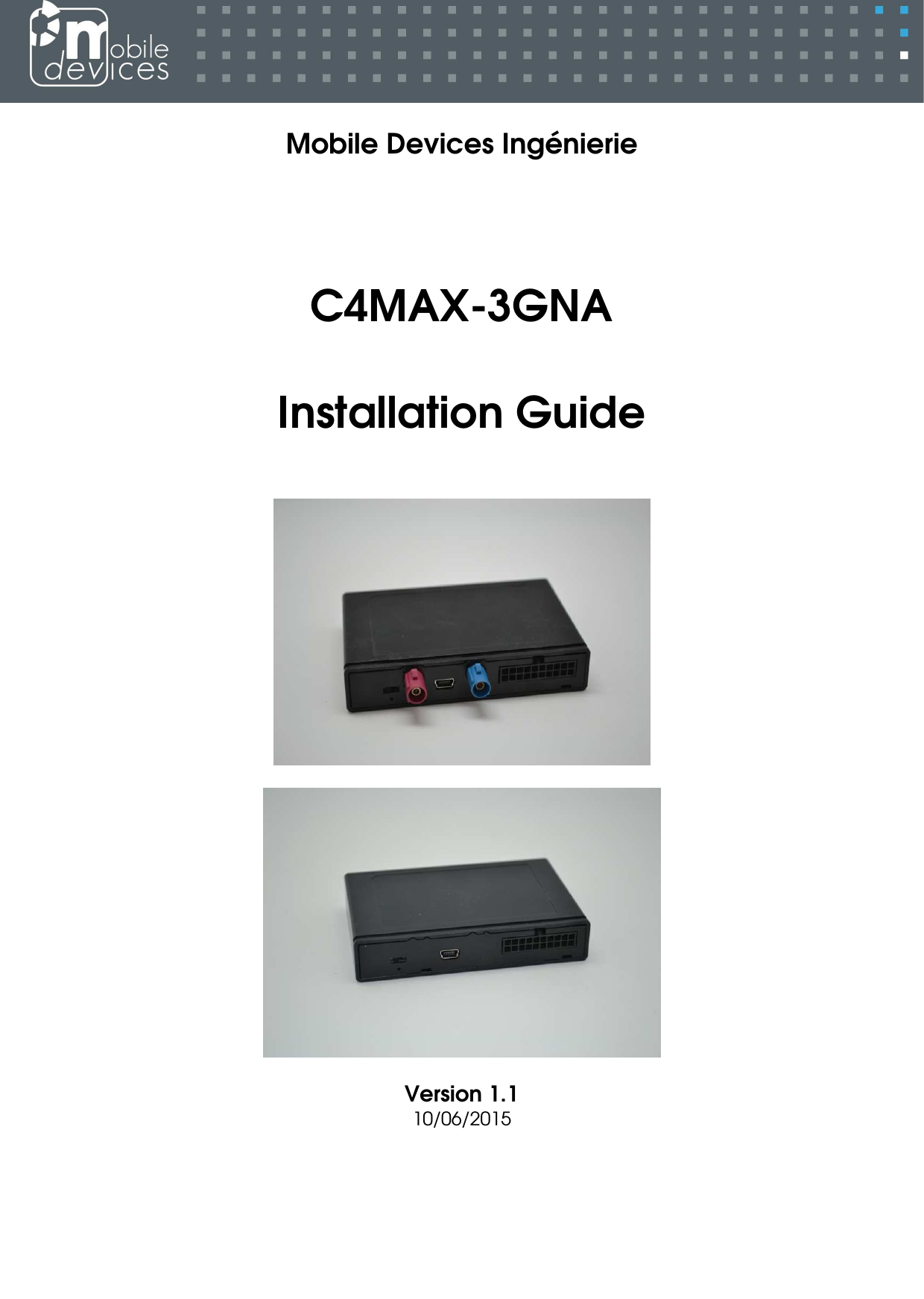
Mobile Devices Ingenierie C4MAX-3GNA Telematics embedded system User Manual
Mobile Devices Ingenierie Telematics embedded system
UserManual.wiki
>
Mobile Devices Ingenierie
>
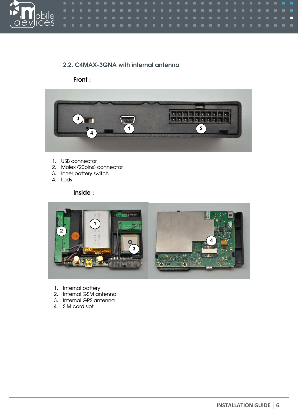
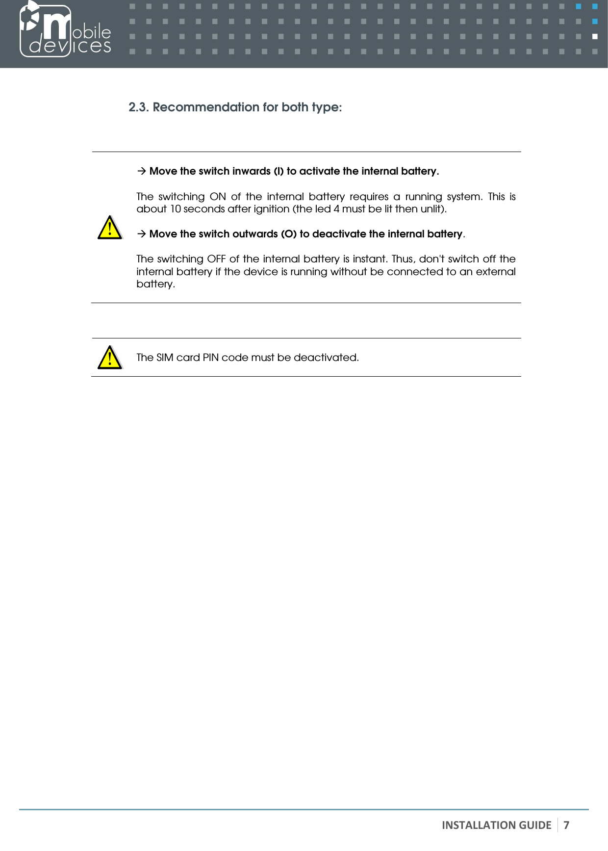
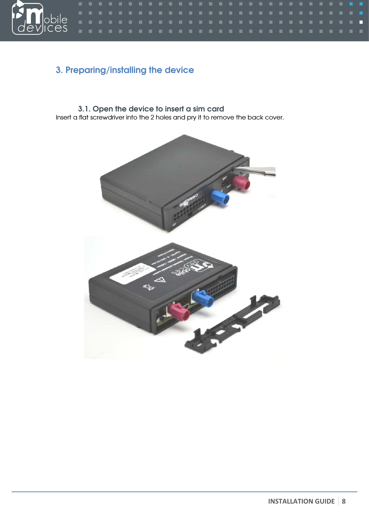
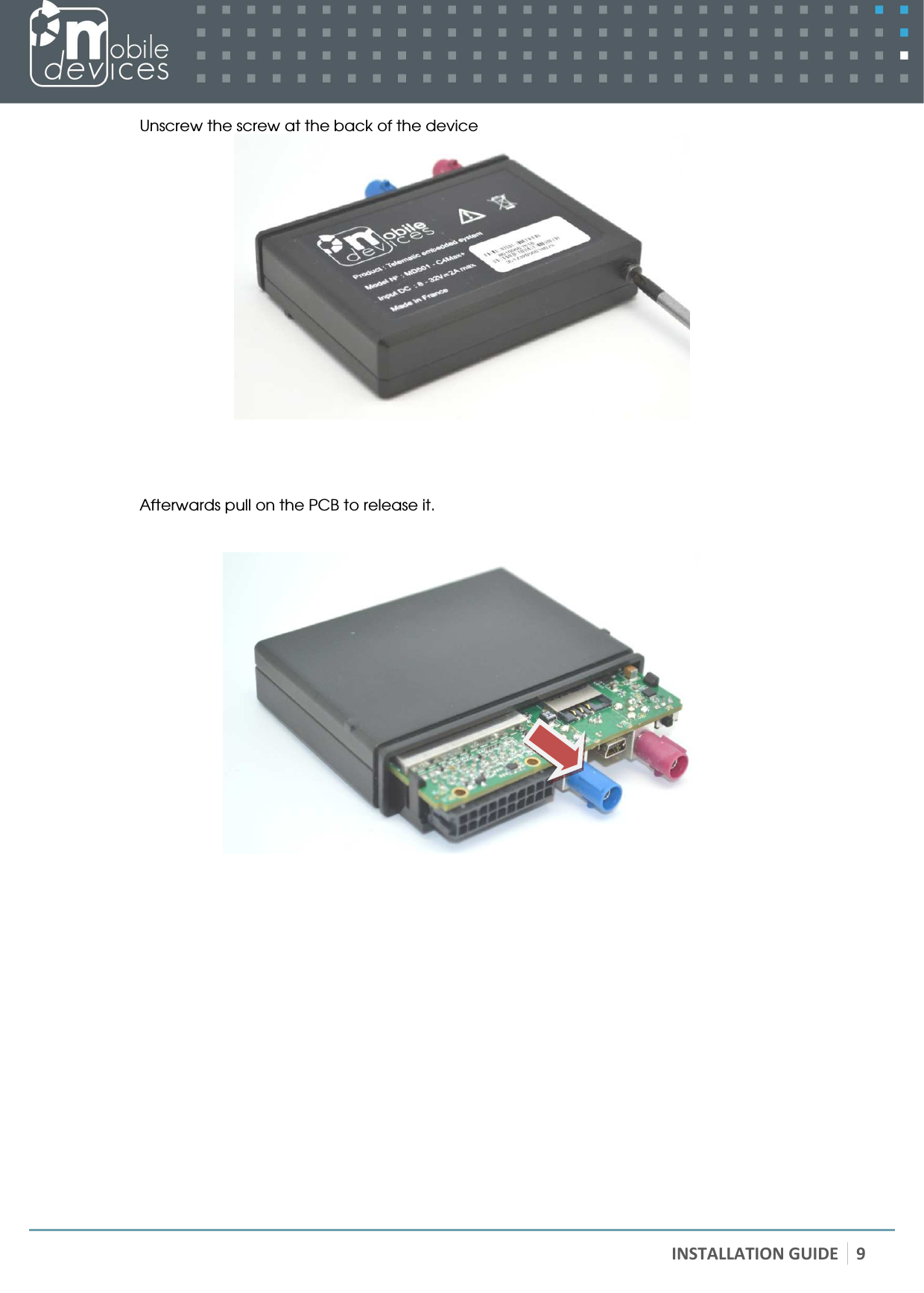
C4MAX 3GNA User Manual
User manual
Navigation menu
Upload a User Manual
Namespaces
Wiki Guide
HTML
PDF
Info
Views
User Manual
Discussion / Help
Navigation