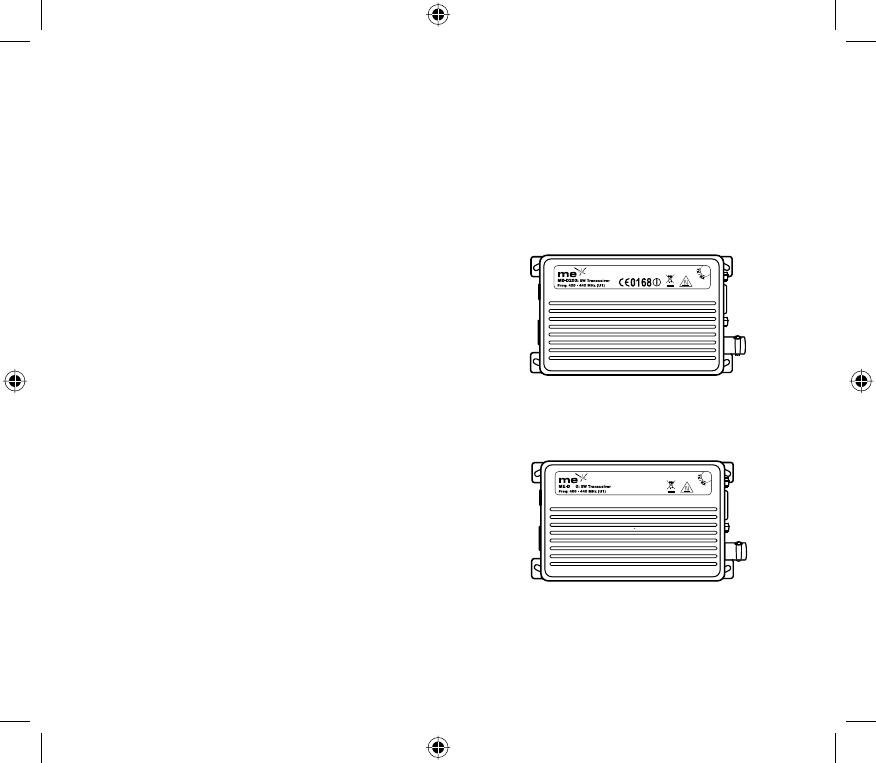
Mobile Expertise D350V2 PMR Transceiver User Manual ug d200 D350 44 v1 0 5 indd
Mobile Expertise Ltd PMR Transceiver ug d200 D350 44 v1 0 5 indd
Contents
- 1. User Manual Cover
- 2. User Manual
User Manual

1
Contents
Introduction ...................................................................... 2
Preparing for use ............................................................. 3
Unpacking and inspection......................................... 3
Description of modem ............................................... 4
Features.................................................................... 5
External connections ................................................ 6
Pin outs ..................................................................... 7
Channel selection ................................................... 14
Operation ....................................................................... 14
Transmit/receive operation ..................................... 14
Serial commands .................................................... 15
Commands and data .............................................. 16
Standard radio commands...................................... 19
Scanning ............................................................. 19
Timings ................................................................ 19
Busy channel lockout........................................... 19
Internal module timings ....................................... 20
Power save mode................................................ 20
Squelch ............................................................... 20
Status indicators and audible alerts ........................ 20
Programming .......................................................... 23
Installation ..................................................................... 23
Antennas................................................................. 23
Power sources ........................................................ 24
Fuse replacement ................................................... 24
Cabling.................................................................... 24
Fixing ...................................................................... 25
Safety and general information...................................... 26
Exposure to radio frequency energy ....................... 26
Electromagnetic interference/compatibility ............. 26
Medical devices ...................................................... 26
Vehicles with airbags .............................................. 27
Potentially explosive atmospheres ......................... 27
Warranty and repairs ..................................................... 27
Care of the equipment ................................................... 28
Disposal / Recycling ...................................................... 28
Declaration of conformity ............................................... 29
FCC & Canadian specifi cations .............................. 29
R&TTE European Specifi cations.............................30
2 3
Introduction
The me-d200/d350 range is a 1 to 5 Watt radio data
modem, which can be used for data up to 9600 baud rate
(using GMSK module) in stand alone conditions.
The me-d200/d350 is housed in a rugged cast-aluminium
box sealed to IEC 529 (IP54) making it suitable for a wide
range of mobile and fi xed applications.
All me-d200 modem units meet the essential requirements
of the relevant European directives and all me-d350
modems meet relevant US FCC and Canadian regulations.
In order to maintain this compliance the installation and
safety information must be adhered to at all times.
The me-d200/d350 modem must only be installed where
unintentional contact cannot be made. The surface of
the device may be hot to touch under certain transmit
conditions. A warning label is permanently displayed as
part of the equipment rating label affi xed to the lid. The
me-d200/d350 is not designed for permanent transmis-
sion. If prolonged transmission periods are used, the
unit will become hot and will require an additional
heatsink to be fi tted.
When fi tting the me-d200/d350 into a fi xed installation,
care must be taken in the routing of all cabling such that
the insulation cannot become damaged.
The recommended supply sources for use with the me-
d200/d350 are a standard 12V supply, but is capable of
operating in the range
(9V - 18V).
●
●
●
Preparing for use
Unpacking and inspection
Unpack the modem and check that you have received the
following items:
me-d200 or d350 Transceiver
User Guide (this document)
me-d200 diagram
me-d350 diagram:
If any of these items are missing, please contact your
supplier.
●
●
e11 034663
35

4 5
Description of modem
The me-d200/d350 is a network free, point to point data
radio that offers great fl exibility in varied applications where
wireless data or voice communication is needed.
It can be used as a “dumb” radio, with no internal module
fi tted, to allow users to facilitate the use of their own
modem and protocol. Internal link changes enable the input
to be set for TTL levels so allowing POCSAG for example.
In this scenario, the radio is completely transparent and
simply needs the correct signal level inputs (see pin out
details), and use of separate control lines (PTT etc) or
serial commands.
The me-d200/d350 can also be fi tted with either a Bell
202,V.23 module, a FFSK module (up to 4800 baud rate)
or a GMSK module (up to 9600 baud rate). These allow
communication with a pc via hyper terminal and other
emulation packages. For further information on these
options, including pin outs, please refer to the separate
Module Manual available on the Mobile Expertise web site.
The me-d200/d350 also operates as a standard radio with
microphone input and speaker output, in this mode the
radio has the following associated features, these include
CTCSS/DCS, busy channel lockout and scan
Features
Compact and rugged die cast box
Resistant to dirt, dust and water ingress (IP54 rated)
Network free, point to point communication
1/5 watt programmable output power
Synthesised operation with 16 channel capability
CTCSS & DCS encode and decode
programmable 12.5 / 25kHz channel spacing
External modem / Direct FM / TTL (pocsag)
Internal (RS232) module options available:
GMSK up to 9600 or
FFSK up to 4800 or
Bell 202 V23 1200bps
RSSI level indication
Busy’ output
9 – 18 volt supply input
Enhanced Power Save Mode (sleep)
Serial commands available to control radio
Busy Channel lockout
Time out timer
Scanning
TX only feature
Programmable squelch levels
●
●
●
●
●
●
●
●
●
●
●
●
●
●
●
●
●
●
●
6 7
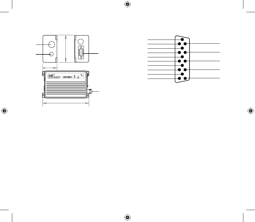
External connections
1 HD 15-way d-type (data and control signals)*
2 BNC antenna connection
3 Accessory aperture
4 Accessory aperture
*The power supply is connected via pin14 (+ve) and pin 4
(GND) of the 15 way D-type.
Pin outs
Pin-outs of DB-15 connector.
The table on the following pages indicates the DB-15 Pin
descriptions with input and output levels.
DATA MOD IN 1
2
3
4
5
6
7
8
9
10
Data OUT (AF)
PTT IN
GND
SERIAL OUT (PROG.)
BUSY
MIC IN (AF)
SERIAL IN (PROG.)
SPK OUT
RS232 DATA (OPT)
11
12
13
14
15
RS232 DATA OUT (OPT)
SERIAL BUSY OUT (OPT)
GPS DATA IN (OPT)
+VE IN
GPS DATA OUT (OPT)
66mm
30mm
117mm
4
1
2
3
e11 034663

8 9
3 PTT In
(Tx Key) Signal, which keys the
transmitter, when operating as
a dumb radio.
Note: If the option module is
installed, RS232 levels must
be selected on CON407. See
Module manual.
TTL level
0V = Tx
open cct = Rx
RS232 level (option)
+12V = Tx
-12V = Rx
I/P
4 Ground Ground connection to chassis
of the radio. 0V (Chassis)
5 Program Data Out/
Serial Data Output Programming data output /
Serial data output. TTL level
(programming cable
has RS232 converter)
O/P
6 Busy
(CD) Logic level output to indicate
presence of a carrier.
Note: If the option modem is
installed, RS232 levels must
be selected on CON407. See
Module manual.
TTL level
0V = carrier
5V = no carrier
RS232 level (option)
+12V = carrier
-12V = no carrier
O/P
Pin No. Function Description Signal Type I/O
1
Program
Data modulation IN.
(used with an external
modem)
AC coupled signal directly
injected through data low pass
fi lter without pre-emphasis.
Input signal
1KHz audio at 60%
peak dev. input level =
100 to 120mVrms
I/P
1
Program option
POCSAG input DC coupled direct signal
designed to work with TTL
level signals only
TTL Levels I/P
1
Program Opt &
h/w changes
AC coupled FM direct
modulation
AC coupled direct FM signal,
without fi ltering
350mV @ 60%
adjustable
I/P
1
h/w changes
DC data modulation IN DC coupled direct FM signal,
without fi ltering
1.9V dc offset 450-
550mV @ 60%
I/P
2 Data OUT
(RX disc)
Discriminator Audio,
unprocessed AF signal
1KHz audio at 60%
peak dev. produces
200 to 300mVrms
O/P

10 11
Pin No. Function Description Signal Type I/O
7
(default) Audio IN
(Mic) / Monitor Audio signal that is fi ltered
(high pass and pre- emph)
then follows same route as
data mod through LPF. Sub-
audio tone is mixed with audio
after the LPF.
1KHz audio at 60%
peak system deviation
input level = 6 to 8mV
rms
I/P
Grounding line activates
monitor action <100k resistor to
ground
7
Link option RSSI RSSI Level 1 to 3.5 V O/P
8 Program data IN/ serial
command Used for serial command for
radio control or is used for
inputting programming data
TTL level (RS232
converter in
programming cable)
I/P
9 Audio OUT Audio output from the audio
amplifi er.
Filtered by tone-fi lter and de-
emphasis circuit.
1KHz audio at 60%
peak dev. produces
nominal 1Vrms @ 8Ω
O/P
10 RS232 Data IN for
option module Data input when the option
module board is installed. RS232 level I/P
11 RS232 Data Out for
option module Recovered data output when
the option module is installed.. RS-232 level O/P
12
(default) Buffer status( busy) for
option module
(reserved)
Indicates buffer status to
prevent data loss according to
buffer overrun
RS-232 level O/P
12
Link option Lock Detect signal PLL lock detect signal >3V out of lock
<0.5V in lock O/P

12 13
*This input can be used as direct FM and can be used for
FSK if the signal level is within the limits.
Link options: To be carried out with reference to the layout
and must be carried without any damage to the pcb. Any
damage will invalidate the warranty.
Refer to Application Notes for details of link changes.
Application Notes can be found on the mobile expertise
web site.
Pin No. Function Description Signal Type I/O
13 GPS data input Data input for initial setting of
GPS module. (NMEA 0183
format)
TTL level I/P
14
(default) VCC in +12 volts
nominal Power supply input, operation
outside the stated range
will be subject to degraded
performance
+12 volts nominal
9v-18v extreme I/P
14
Link option DGPS data input Data input for DGPS
Correction of GPS module.
(NMEA 0183 format)
TTL level I/P
15 GPS data output Position data output from the
GPS module.
(NMEA0183)
TTL level O/P
14 15
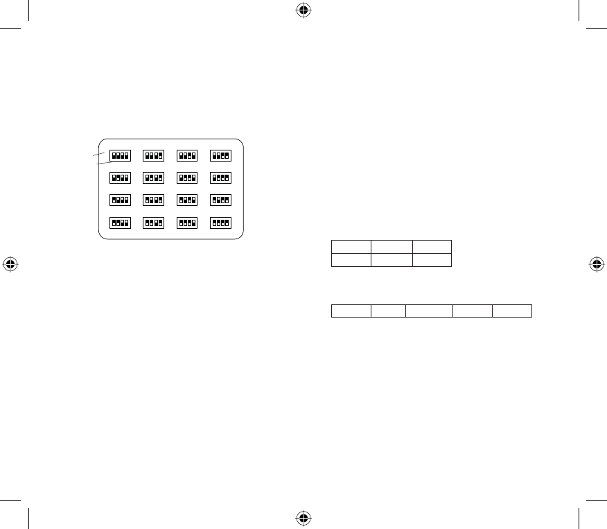
Channel selection
Channels are selected by the use of internal switches and
can be set as shown below. The bottom 4 screws will
need to be removed to gain access to the switches, care
must be taken to avoid any damage which could invalidate
the warranty.The channel can also be changed by a serial
command inputted from the external control system.
Figure: Setting of channel selector switch for each channel
By altering link options, channel change can also be
implemented using TTL levels on pins 11,12,13 & 15 of
DB15 way assuming these pins are not in use and default
conditions are met. Refer to Application Notes on the
Mobile Expertise web site.
Operation
Transmit/receive operation
The me-d200/d350 can be put into transmit by different
methods. When used as a “dumb” radio, the PTT line is
pulled low (pin 3 of DB15). The Tx serial command will
also put the radio into transmit (pin 8 of DB15), until the Rx
serial command is received.
Where an internal module is fi tted the PTT/Busy links are
changed to RS232 (see module manual). The GMSK and
FFSK can in addition operate automatically by going into
“TX” on receipt of data on pin 10 of DB15.
Serial commands
The modem can be controlled by using the serial command
(pin 8) data in, sending commands to the radio such as
PTT or change channel
The format for these commands (asynchronous) are:
Baud rate: 4800 bit/sec
Data: 8 bit,
Parity: Non parity
Stop Bit (SP): 1 bit
MSB fi rst transmission
Each serial command consists of 3 bytes. The fi rst byte is
the command (CMD), the second is data (DATA) required
by the command and the third is the check sum (CS) to
validate contents
TX Command format:
CMD DATA CS
1st byte 2nd byte 3rd byte
N.B. Check Sum = 1st byte + 2nd byte. CS = CMD + DATA
Response format:
CMD DATA1 DATA2 ... DATAn
The response CMD is in the form of:
ACK, acknowledge, Hex: 0xAA; (then data if any)
NACK, no acknowledge (error in command) Hex: 0x55
NOK, not okay (cannot carry out command) Hex: 0x65
If command is not recognised, repeated or already in
requested or wrong state e.g channel change in TX there is
no response from the radio.
●
●
●
●
●
1234
1
16
234
5678
9101112
151413
SW401
CHANNEL NO.
SWITCH POSITION
1234 1234 1234
1234 1234 1234 1234
1234 1234 1234 1234
1234 1234 1234 1234

16 17
Commands and data
Mode Transmit
command
(CMD)
Transmit
Data
(DATA)
Response
(CMD) Response Data Remark
Channel Change 0x64 0x00 : chn 1
0x01 : chn 2 0xAA (ACK)
0X55 (NACK) No response if in transmit
mode
Request current
Channel 0x53 0x66 ACK / NACK 1st byte: Chn no.
2nd byte: option board
status
Chn 1 = 01 Chn 2 = 02
A0: No option board
A1: GMSK
A2: FFSK/AFSK
Activate prog
mode / main
loop
0x87 0x00 ACK / NACK
No response
on earlier
models
Cannot receive in this mode,
but clears previous serial
commands. Use 0x53 to rx
mode
Request current
channel number,
when in prog
mode
0x53 0x66 ACK / NACK 1st byte: chn no.
2nd byte: software
version
3rd byte: option board
status
Chn 1 = 01 Chn 2 = 02
Software version 1.2 = 12
A0: No option board
A1: GMSK
A2: FFSK/AFSK
*Software
version 0x59 0x00 ACK / NACK 1st byte main ver
2nd byte update ver 2 bytes in Hex represent
version e.g. 1.10 becomes
01,0A
*Firmware version 5.0 or later
Enter TX mode 0x61 0x74 ACK / NACK No response if already TX
Enter RX mode 0x61 0.72 ACK / NACK No response if already RX
Enter Sleep
mode 0x57 0X4f ACK / NACK Firmware 5.0 or later
Exit Sleep mode 0x57 0x58 ACK / NACK Firmware 5.0 or later
Check radio
awake 0x6a 0x00 ACK / NACK
Scan start 0x62 0x73 ACK / NACK No response if already
scanning
Scan start, but
stopped on
correct channel
0x62 0X46 0X66 Chn no., CMD+DATA Respond once if stopped on a
channel. e.g.If on channel 1 :
66,00,66 (00=chn1,01-chn2)
Scan Stop 0x62 0x46 ACK / NACK
Scan delete 0x62 0x4f ACK / NACK
0X65 (NOK)
NOK : e.g when stopped not on
a channel

18 19
IStandard radio commands
Scanning
A scan function is available whereby any or all 16 channels
can be monitored for activity. Scanning parameters such
as scan speed and delay are programmable (refer to
programming guide)
Control of the scan channels is by serial commands.
Note The priority channel (the transmit channel during
scanning) is the channel selected via the dip switch.
Timings
Radio timings parameters are available for alteration via the
programmer.
These include:
Time-out timer,
Hang timer -transmit after dis-asserting PTT
Tx delay - prevents squelch noise when using CTCSS/
DCS
Busy Channel Lockout
Prevents TX when while the radio is receiving. Refer to
programming guide more more detail.
N.B. Where the module option board is fi tted alternative
programmable functions apply.
●
●
●
Module Test
Message Enable
0x75 0x78 ACK / NACK
Module Test
Meesage Disable
0x75 0x79 ACK / NACK
A comprehensive list of serial commands is available on our web site www.mobile-expertise.co.uk/support

20 21
Internal Module Timings
Tx delay and Rx delay timings are available for alteration
when the internal module is fi tted only. Please refer to the
programming guide and module manual for details
Power Save Mode
The modem will go into power save mode for short periods
of time to minimise power consumption when a battery
supply is being used. Parameters are programmable.
Enhanced Power Save Mode (sleep)
The modem in this mode deactivates all circuitry with
the exception of the micro controller. It is activated and
deactivated using serial commands (see Command List).
Current consumption is signifi cantly reduced to
approximately 7mA and represents an 85% saving on
normal standby consumption.
Squelch
The modem offers 2 forms of squelch, which are
programmable as RSSI level check or busy port .
RSSI level uses the RSSI level from the FM detector
chip and the point of squelch is programmable.
Noise saquelch uses the ‘on board’ circuitry to detect
noise and is manually adjusted.
Status indicators and Audible alerts
The LED indicates the current status of the radio and if
an external speaker is connected to pin 9 of the DB-15,
audible tones can be heard under certain fault conditions.
The details are shown in the table opposite.
●
●
Status Description LED colour Audible tone
(if speaker fi tted)
Normal Power ON Green-Orange-red
Busy channel Orange
Correct Call (with SAT) Green
Transmit Red
Warning Busy channel lockout Green fl ashes beep tone
Time out time Green fl ashes (ptt active)
Red LED extinguishes (serieal
cmd)
5 secs before TOT 1 Green fl ash beep tone
Errors EEPROM error 1 Orange fl ash
Out of lock Continuous Orange fl ashes

22 23
Status Description LED colour Audible tone
(if speaker fi tted)
Errors cont... Comms error with module Green LED fl ash
Transmit hang on time Single beep tone
Wrong model programmed After “Power ON sequence - 2
additional Orange fl ashes.
Program Read Mode Red LED fl ashes
Write mode Green LED fl ashes
Squelch program
mode Initial data load Green-Orange-Red
Open squelch mode Three Green fl ashes
Close squelch mode Two Green fl ashes
Save squelch mode One Green fl ash
Programming
The data modem is pc programmable. The parameters
available for programming include:
Frequency, channel spacing and sub-audible tones on a
per channel basis
Radio settings such as power save mode,Tx lockout, Tx
timeout, Squelch
Module options when FSK, FFSK and GMSK module
is fi tted, such as setting baud rate, dumb or auto mode,
Hyper Terminal mode and data settings (fl ow control,
block size etc)
The pc program also allows for squelch adjustments and
calibration Refer to programming manual and PC software.
Installation
Antennas
It is important that any antennas are installed in a suitable
location with an adequate ground plane. Ideally, multiple
antennas should be separated by a minimum of a
wavelength (at the lowest frequency), whilst still retaining
a good ground plane for each antenna. Therefore, for a
400MHz system, the ideal separation should be a minimum
of 0.75m (~30in), and for 150MHz system the minimum
should be 2.5m (~98in).
Warning: If installing an antenna near people it is necessary
to ensure the minimum separation is maintained. This
particularly important where prolonged exposure is likely.
For a full range of antenna options and other accessories
visit the Mobile Expertise web site.
●
●
●
24 25
Power sources
It is important that a “clean” source of power is used for the
supply to the modem
Fuse replacement
We recommend an inline “quick blow” fuse rating of 4 amps
be fi tted to the +ve supply.
Cabling
If possible, run RF cables separately from other cables
and keep RF cables apart from one another to avoid
interference / coupling.
When fi tting the modem into a fi xed installation care must
be taken in the routing of all cabling such that the insulation
cannot become damaged.
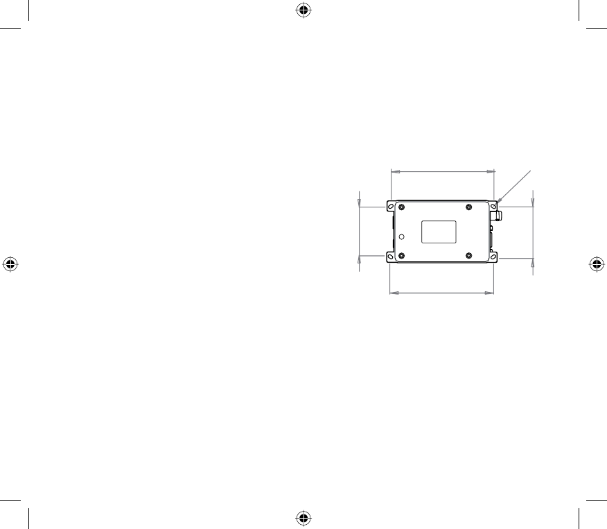
Fixing
We recommend that the me-d200/d350 is securely fi xed
to a surface, either directly, or with a suitable bracket. The
fi xing hole centre dimensions are as shown.
The modem can be attached to any surface by using
suitable size screws through the M3.5 holes in the
mounting fl anges.
52.045mm +/-0.305
108.763mm +/-0.0762
3.5mm Clearance
50.06mm +/-0.250
108.763mm +/-0.0762

26 27
Safety and general information
Important information on safe and effi cient use of your
Radio device
Exposure to radio frequency energy
Your modem is a high power radio transceiver. When
it is on, it receives and also sends out radio frequency
(RF) signals. To help minimise human exposure to RF
electromagnetic energy, keep transmission time to 50%
or less.
As with all radio devices, holding the antenna affects
transmission quality and may cause the radio to operate at
a higher power level than required. Do not hold the antenna
when the radio is in use.
Do not use radios with damaged or modifi ed antenna,
this may violate compliance with relevant international
standards.
Where prolonged human exposure is likely, the minimum
separation from the antenna should be 0.8m.
Electromagnetic
interference/compatibility
Most modern electronic equipment is shielded from RF
energy. However certain electronic equipment may not
be shielded against RF signals. The modem needs to be
switched off in any facility where posted notices instruct
you to do so to avoid electromagnetic interference or
compatibility confl icts. Special care should be taken near
facilities such as hospitals or health care centres may be
using equipment that is sensitive to external RF energy.
Medical devices (Pacemakers)
If you use any personal medical device, consult the
manufacturer of your device to determine it is adequately
shielded from RF energy. Your physician may be able to
assist you in obtaining this information.
Vehicles with airbags
Air bags infl ate with great force. Do not place a radio in the
area over an airbag or in the airbag deployment area, any
radio may be propelled with great force and cause serious
injury to the occupant of the vehicle.
Potentially explosive atmospheres
Turn off your modem prior to entering any area with a
potentially explosive atmosphere, unless it is a radio
type especially qualifi ed for use in such areas. Do not
remove install or charge batteries in such areas. Sparks in
potentially explosive atmospheres can cause an explosion
or fi re resulting in bodily injury or death.
Potentially explosive atmospheres include fuelling areas
such as petrol stations, below decks on boats, fuel or
chemical transfer or storage facilities, vehicles using liquid
petroleum gas (such as propane or butane); areas where
the air contains chemicals or particles such as grain, dust
or metal powders, and any other area where you would
normally be advised to turn off your vehicle engine. Areas
with potentially explosive atmospheres are often but not
always posted.
28 29
Warranty and repairs
The me-d200/d350 is a low maintenance device. Once
installed it requires no ongoing maintenance.
In the event that your Mobile Expertise me-d200/d350
modem needs repair, return your radio to an authorised
Mobile Expertise supplier. Do not disassemble, modify
or repair the unit unless the work is carried out by a
Mobile Expertise approved supplier. Incorrect assembly,
modifi cation or repair may cause irreparable damage to
your unit and will invalidate any warranty.
Care of the equipment
Do not immerse the me-d200/d350 modem in water or
other fl uids.
Do not use solvents or spirits for cleaning as this may
cause damage to the case materials.
Do not over tighten connection to the modem.
Disposal / Recycling
The me-d200/d350 is a Class 3 product in accordance with
the Waste of Electrical and Electronic Equipment (WEEE)
Directive. Disposal of this class of equipment must be
carried out through an authorised recycling centre.
●
●
●
Declaration of conformity*
The me-d200/d350 range is a 1 to 5 Watt radio data
modem, in V2 (146-173MHz), U1(400-440MHz) or U2 (440-
480MHz) frequency ranges,
These frequencies are licensed, restriction of use may
apply in some countries.
This equipment is intended for use in:-
Model me-d200:
Austria, Belgium, Czech Republic, Cyprus, Denmark,
Estonia, Finland, France, Germany, Greece, Hungary,
Ireland, Italy, Latvia, Lithuania, Luxembourg, Malta,
The Netherlands, Poland, Portugal, Slovakia, Slovenia,
Spain, Sweden, Switzerland, United Kingdom, Iceland,
Liechtenstein, Norway, Bulgaria, Romania & Turkey.
Model me-d350:
United States of America & Canada.
This equipment can also be used worldwide, where the
equipment is approved for use.
FCC / Canadian Specifi cations
FCC Part 15*, 90
Canada RSS-119 issue 9 2007
*This device complies with Part 15 of the FCC Rules.
Operation is subject to the following two conditions:
1) This device may not cause harmful interference, and
2) This device must accept any interference received,
including interference that may cause undesired
operation.
Any change or modifi cation to the product not expressly
approved by Mobile Expertise Ltd. could void the user’s
authority to operate the device.
This equipment complies with FCC radiation exposure
limits set forth for an occupational/controlled environment.
This equipment should be operated with a minimum
distance of 20cm between the radiator and your body. A
maximum antenna gain of 0dB at 1W (low power) and -7dB
at 5W (high power) should be used with the equipment in
order to maintain the 20cm distance.

30 31
R&TTE Specifi cations
Art. 3.1 (a) EN 60950-1:2002/A1:2005
SAR BS EN 50371:2002
Art. 3.1 (b) EN 301 489-1 V1.4.1 (2002-08)
EN 301 489-1 V1.6.1 (2005-09)
EN 301 489-5 V1.2.1 (2000-08)
EN 301 489-5 V1.3.1 (2002-08)
Art. 3.2 EN 300 113-2 V1.1.1:2001
EN 300 113-2 V1.3.1:2003-12
EN 300 113-2 V1.4.1:2007-07
EN 300 113-1 V1.5.1:2003
EN 300 113-1 V1.6.1:2007
EN 300 220-2 V2.1.2 (2007-06)
EEC Automotive
Directive
72/245/EC (2004/204/EC)
E11 10R 024663
e11 034663
This is a Class II product in accordance with the R&TTE
Directive, 1999/5/EC.
We hereby declare that the above named product is in
conformity to all the relevant essential requirements of
Directive 1999/5/EC.
Wir möchten hiermit bekanntgeben, daß das oben
genannte Produkt in Übereinstimmung mit allen
erforderlichen Bedürfnissen der 1999/5/EC Direktive seht
Certifi camos que el aparato es conforme con lo establecido
en las disposiciones de la Directiva 1999/5/CE.
Nous déclarons que le produit référencé ci-dessus satisfait
aux exigences R&TTE 1999/5/EC qui lui sont applicables.
*A signed and dated Declaration of Conformity is available
on request.
Published by Mobile Expertise Limited.
Any queries regarding information in this manual, please
contact the Technical Services Group Leader at the above
address.
Information provided in this document is believed correct at
time of printing but is subject to change without notice.
Mobile Expertise Limited will not accept liability for any
loss, damage or costs howsoever caused as a result of the
information provided.
Mobile Expertise Limited
Version 1.0.5
This user guide is published by Mobile Expertise Limited.
Improvements and changes to this user guide necessitated
by typographical errors, inaccuracies of current information,
or improvements to programs and/or equipment, may be
made by Mobile Expertise Limited at any time and without
notice. Changes will be incorporated into new editions of this
user guide.
© Mobile Expertise Limited, 2010.
0168