Mobile Knowledge MKC900XY2Z Mobile Data Terminal User Manual File Properties Title
Mobile Knowledge Corp. Mobile Data Terminal File Properties Title
User Manual

Series 9000 SDK Getting Started Manual
REVISION HISTORY
Date Revision Description
22 April 2005 A0 Initial Draft – Travis Gray
28 April 2005 A1 Updates with Cable Specifics
14 November 2006 A2 Notes Related to Limites of Intel Strata Flash Component
2 April 2007 A3 GPRS References Added as Section 4.
28 June 2007 A4 Updated GPRS Safety Notification.
9 July 2007 A5 Added additional statement to GPRS Safety Notification.
Copyright
Copyright © 2005 Mobile Knowledge Corp All Rights Reserved.
This document and the subject matter contained herein are proprietary items to which Mobile Knowledge
Corp. retains exclusive rights to reproduction, manufacture, and sale. This proposal is submitted in
confidence, for the use of the recipient alone, or in conjunction with Mobile Knowledge Corp. and its
licensees, and for no other purpose whatsoever unless permission for further disclosure is expressly
granted in writing. Information in this document is subject to change.
For additional copies of this document, please contact:
Mobile Knowledge Corp
308 Legget Drive
Kanata, Ontario, Canada, K2K 1Y6
Phone: 1-613-287-5020
Fax: 1-613-287-5021
e-mail: info@mobile-knowledge.com
web: www.mobile-knowledge.com
9000 SDK Getting Started - A5.doc © Mobile Knowledge Corp. Page 2 of 17

Series 9000 SDK Getting Started Manual
9000 SDK Getting Started - A5.doc © Mobile Knowledge Corp. Page 3 of 17

Series 9000 SDK Getting Started Manual
TABLE OF CONTENTS
Revision History.......................................................................................................................................... 2
Table of Contents........................................................................................................................................ 4
1. Introduction ...................................................................................................................................... 5
1.1 What’s Included ..............................................................................................................................5
1.2 What’s in this Document................................................................................................................. 6
2. System Description.......................................................................................................................... 7
2.1 Series 9000 MDT Hardware ........................................................................................................... 7
2.2 Series 9000 MDT Software ............................................................................................................ 8
2.3 The Series 9000 SDK Software...................................................................................................... 9
3. Working with the Series 9000 MDT...............................................................................................10
3.1 Powering the Series 9000 ............................................................................................................ 10
3.2 Initial Hardware Setup (RS-232 Serial) ........................................................................................ 10
3.3 Subsequent Hardware Setup (Ethernet) ...................................................................................... 11
3.4 Software Setup ............................................................................................................................. 11
3.5 Development PC Setup ................................................................................................................ 12
3.6 The Series 9000 SDK API Library and Online Help File ..............................................................13
4. Optional Public Data Radio Modem ............................................................................................. 15
4.1 Safety Notification:........................................................................................................................ 15
5. Additional Resources .................................................................................................................... 16
6. Series 9000 Cabling ....................................................................................................................... 17
6.1 Cable - Series 9000 Power (PN 850-0231-000)........................................................................... 17
6.2 Cable – Series 9000 COM/IO (PN 850-0230-000)....................................................................... 17
6.3 Cable – Series 9000 COM Extender (PN 850-0233-000) ............................................................ 17
9000 SDK Getting Started - A5.doc © Mobile Knowledge Corp. Page 4 of 17
Series 9000 SDK Getting Started Manual
1. INTRODUCTION
The Mobile Knowledge Inc. Series 9000 Software Development Kit (SDK) includes everything you need
to develop applications on the Series 9000 Mobile Data Terminal (MDT). The MDT and development
environment are described in Section 2 – System Description.
1.1 What’s Included
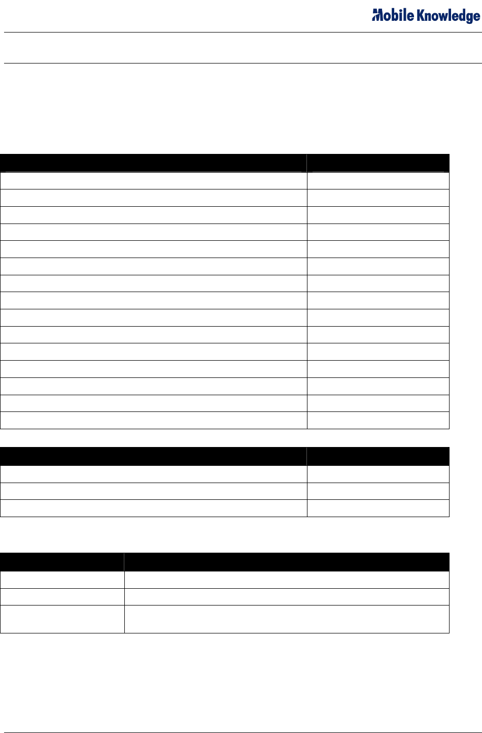
The Series 9000 SDK ships with the following hardware and software:
Hardware Part Number
Series 9000 MDT 960-2470-xxx
Series 9000 Accessories Kit 360-2437-000
GPS Antenna (Magnetic Mount) 360-0004-SMA
Cable - Series 9000 Power 850-0231-000
Cable – Series 9000 COM/IO 850-0230-000
Cable – Series 9000 COM Extender 850-0233-000
Power Switch 650-0074-000
Emergency Switch 550-0111-000
Emergency Switch Collar 550-0112-000
Wire, Terminal Lugs, Mounting Screws, Fuse, Tie Wraps Various
Compact Flash Ethernet Card (Socket Communications) 383-0003-000
Patch Cable (7ft, Black, Cat 5, RJ45-RJ 45) 550-0153-000
Cross-Over Cable (8ft, Cat 5, RJ45-RJ45) 850-0189-000
Null Modem Adapter (10ft, F-F) 850-0227-000
Mounting Bracket – HINT Dashboard 750-0002-000
Software Part Number
Series 9000 SDK Software Kit (CD) (includes CE Image) 475-2470-004
Series 9000 SDK License Agreement TBD
Getting Started Manual (PDF file on CD) 460-2470-004
The software CD contains the following:
SDK CD Directory Contents
Series 9000 SDK Readme.txt – this file contains basic getting started information.
Series 9000 SDK Cables PDF files of the cable drawings and pin assignements.
Series 9000 SDK Manual Series 9000 SDK Getting Started Manual in PDF format
(this manual)
9000 SDK Getting Started - A5.doc © Mobile Knowledge Corp. Page 5 of 17

Series 9000 SDK Getting Started Manual
1.2 What’s in this Document
The Series 9000 SDK Getting Started Manual contains the following information:
1. Section 2 – System Description
• This section contains descriptions of the Series 9000 MDT and the tools provided on the SDK
CD.
2. Section 3 – Working with the Series 9000 SDK
• This section contains descriptions and instructions for the hardware and software setup to get
started with development of applications using the Microsoft® eMbedded Visual Tools® and
the Series 9000 SDK API. The sample eMbedded Visual Basic® and Visual C++® programs
are described.
3. Section 4 – Optional Public Data Radio Modem
• Provides cautions pertaining to Series 9000 configurations incorporating internal Wavecom
Q2406/Q2426 internal GPRS modem module.
4. Section 5 – Additional Resources
• This section contains links to additional resources for pertinent Microsoft eMbedded
information.
5. Section 6 – Series 9000 Cabling
• Provides drawings of cables included with standard Series 9000 accessories kit.
9000 SDK Getting Started - A5.doc © Mobile Knowledge Corp. Page 6 of 17

Series 9000 SDK Getting Started Manual
2. SYSTEM DESCRIPTION
This section describes the hardware and software configuration of the Series 9000 SDK.
2.1 Series 9000 MDT Hardware
The Series 9000 MDT features a 5.7” ¼VGA display with a resistive touch screen. The Microsoft
Windows CE.Net operating system runs on the embedded Intel 200 MHz processor. The onboard
peripherals and IO capabilities of the Series 9000 are illustrated in Figure 2-1 and described in Table 2-1:
Figure 2-1 – Series 9000 MDT
9000 SDK Getting Started - A5.doc © Mobile Knowledge Corp. Page 7 of 17
Series 9000 SDK Getting Started Manual
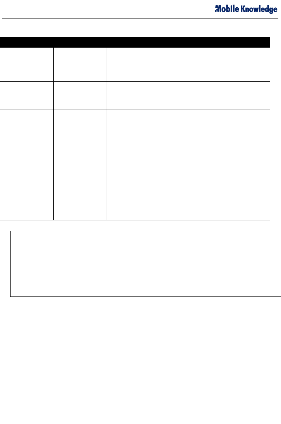
Table 2-1 – Series 9000 MDT Peripherals and I/O
Device Description Uses
Display with
Resistive Touch
Screen
5.7" ¼VGA with
Resistive Touch
Screen
The 5.7" ¼VGA (320 X 240 pixels, 16 bit color) display features a
resistive touch screen. A software input panel keyboard is available
on the unit, but alternately, a USB keyboard can be plugged into
the Series 9000 USB port. The display is controlled via the
Windows API.
Magnetic Card
Swipe
Standard Track-I
and Track-II
Magnetic Card
Swipe
The magnetic card swipe is a two-track reader. Track-I and Track-II
data is accessible via the Series 9000 SDK.
Microphone,
Speaker
Audio Input and
Output
The sound features of the Series 9000 MDT are accessed through
standard Windows API calls.
Compact Flash Slot Compact Flash Slot The CompactFlash I/O slot allows expansion via CF devices such
as network cards, memory storage cards, etc. The CF functions are
controlled via the Windows API.
MMC Slot MMC Slot The MMC I/O slot allows memory expansion via MMC format
memory cards. The MMC functions are controlled via the Windows
API.
GPS Connector Standard GPS
connector
The GPS antenna connector is used to connect a 3V GPS
antenna. The GPS data is accessed through NMEA strings
exposed by the Series 9000 SDK.
DB-26 Connector DB-26 Connector The DB-26 connector provides access to power, I/O, USB, and four
RS-232 serial ports. Appendix A describes specifies the pin
assignments associated with the primary and secondary I/O
cables.
Note: The Series 9000 Mobile Data terminal contains two types of embedded memory. The
MDT has 64MB of RAM, and 64MB of Flash memory. The SDK developer has approximately 40MB
of available space in the Intel Persisten Memory Manager section of Flash. This Intel Strata Flash
component is rated for a minimum 100K erase cycles per block. The Intel PSM software also
provides a measure of write-leveling to extend the lifecycle of this component.
Typically, software implementation utilizes RAM memory (not limited in this fashion) for frequent non-
persistent storage. Flash Memory should only be used to store minimum amounts of data as required
to survive a restart. When engineering an application the usage of flash memory must be carefully
calculated and accounted for during the design phase.
2.2 Series 9000 MDT Software
Folders of interest to developers on the Series 9000 MDT are shown in Figure 2-2 and described in Table
2-2:
9000 SDK Getting Started - A5.doc © Mobile Knowledge Corp. Page 8 of 17

Series 9000 SDK Getting Started Manual
Figure 2-2 – Persistent Storage Folders
To access the IPSM folder, open the My Computer icon on the desktop, and then click the IPSM folder
followed by the Windows folder. The IPSM folder provides persistent storage through power cycles
(contents of the IPSM folder are saved to internal flash). The IPSM\Windows folder contains default
subfolders as specified in Table 2-2:
Table 2-2 – Series 9000 MDT IPSM\Windows Directory
Custom Shell Special ShortCuts files place here allow a your custom application to be
launched instead of the Shell.
Desktop Files stored in this folder will appear as desktop shortcuts on power up (if stored
as shortcuts).
Favorites Shortcuts stored in this folder will appear on the My Favorites menus.
Fonts Additional system fonts can be stored here.
Programs Items in this folder will appear in the Start → Programs menu.
Recent Files here will appear in Start→Documents.
Startup Shortcuts to applications in this folder will run at power up.
System Storage for DLL files and other files to be included in Windows path.
NOTE: The contents in folders outside of the IPSM Folder are not saved after re-powering the Series
9000 MDT.
2.3 The Series 9000 SDK Software
The Series 9000 SDK includes SDK components for the eMbedded Visual C++ programming
environment. The Series 9000 SDK Online Help becomes integrated within the eMbedded Visual Tools
Help and provides code level descriptions of the SDK’s API functions.
The Series 9000 SDK CD setup installs the components mentioned above and creates a samples
directory in the Windows CE Tools directory containing examples of eMbedded Visual C++ applications.
9000 SDK Getting Started - A5.doc © Mobile Knowledge Corp. Page 9 of 17
Series 9000 SDK Getting Started Manual
3. WORKING WITH THE SERIES 9000 MDT
Establishing initial communications between the Series 9000 MDT and the Development PC requires the
use of the Microsoft ActiveSync application. Creating the ActiveSync Partnership necessitates a serial
connection to the PC via COM 5 of the 9000 MDT. Once this Partnership has been created, the
Development PC can then communicate with the Development PC via an Ethernet connection using the
Compact Flash Ethernet adapter (PN 383-0003-000) provided as part of the accessories kit.
3.1 Powering the Series 9000
Two steps must be taken to power the Series 9000:
1.
2.
Connect Cable # 850-0231-000 to a 12VDC power supply (Red to DC+, Black to DC-)
Connect the Blue wire of Cable # 850-0230-000 to the +12VDC power source. This is the ignition sense
line for the device, and the Series 9000 will not power unless power is applied to this lead.
NOTE: The “Ignition Run Line” (Blue wire of Cable # 850-0230-000) must be connected to the +12VDC in order
to power the Series 9000.
3.2 Initial Hardware Setup (RS-232 Serial)
The initial hardware setup must be utilized to create the initial ActiveSync Partnership between the Series
9000 and the Development PC. Once this has been accomplished, it will be possible to establish an
ActiveSync connection via an Ethernet link as described in Section 3.
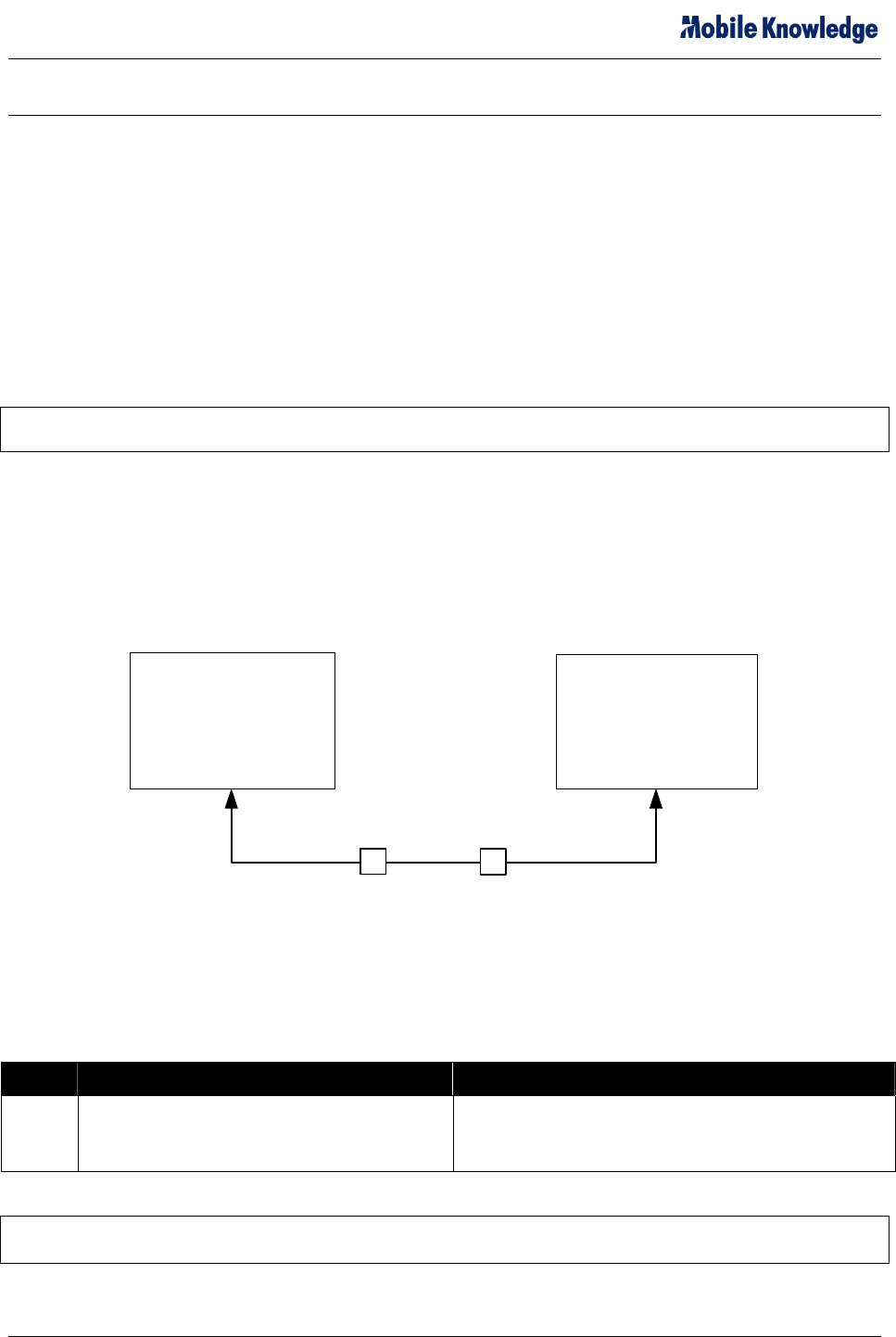
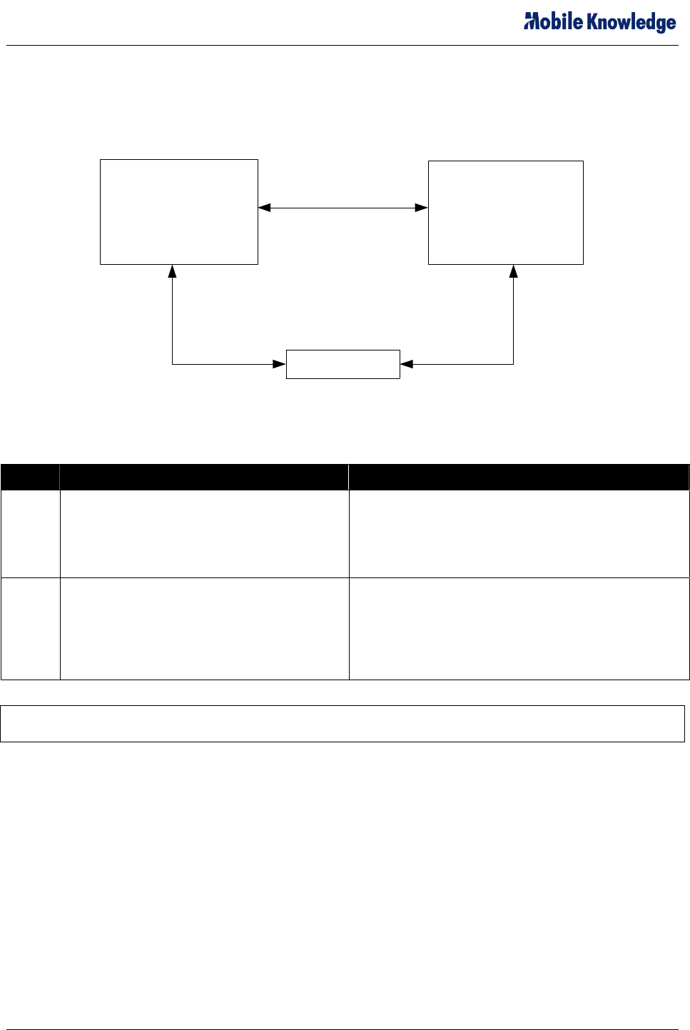
Figure 3-1 illustrates the initial RS-232 Serial connectivity required to establish the initial ActiveSync
Partnership. Table 3-1 describes this connection in greater detail.
Series 9000 Development PC
COM 5 Available
Serial Port
1
Null Modem
Figure 3-1 – Connecting the Series 9000 MDT to your Development PC (RS-232 Serial)
Refer to Section 3.5 for a step-by step description of the procedure required to establish the Partnership.
Table 3-1 – Connecting the Series 9000 MDT to your Development PC
Configuration Use
1 Series 9000 MDT COM 5 to development
PC COM port (COM 1 or 2 – configurable
with ActiveSync)
Used to establish the initial ActiveSync connection
and Partnership through the development PC COM
port.
NOTE: Use COM 5 to initiate a serial connection between the Series 9000 and the Development PC so
as to establish the requisite ActiveSync partnership.
9000 SDK Getting Started - A5.doc © Mobile Knowledge Corp. Page 10 of 17
Series 9000 SDK Getting Started Manual
3.3 Subsequent Hardware Setup (Ethernet)
Figure 3-2 illustrates two configurations used to connect the Series 9000 MDT to the development PC
following the creation of the ActiveSync Partnership described in Section 3.1. Refer to Table 3-2 for
detailed descriptions of both configurations.
Series 9000 Development PC
LAN
CF Ethernet NIC
CF Ethernet NIC
Static IP
2
3
Figure 3-2 – Connecting the Series 9000 MDT to your Development PC (Ethernet)
Table 3-2 – Connecting the Series 9000 MDT to your Development PC
Configuration Use
2 Series 9000 MDT CF Ethernet card to
development PC NIC with static IP.
Used to install the Windows CE image onto the Series
9000 MDT.
The Crossover Cable (PN 850-0189-000) should be
used to connect the Compact Flash Ethernet port of the
9000 to the NIC Card of the PC.
3 Series 9000 MDT CF Ethernet card to LAN on
which development PC is also connected.
Used to establish an ActiveSync connection through a
LAN. Can be done after an ActiveSync “Partnership” is
created though the serial connection.
The Patch Cable (PN 550-0153-000) should be used to
connect the Compact Flash Ethernet port of the 9000 to
your Local Area Network.
NOTE: When establishing the ActiveSync connection through the LAN, ensure the network’s reverse
DNS is enabled, as ActiveSync will search out the machine name, and not its IP number.
3.4 Software Setup
Setting up the software environment on the development PC requires that Microsoft eMbedded Visual
Tools 4.0 be installed before the installation of the Series 9000 SDK.
The steps to be followed in creating the development environment on your development PC are:
1. Install Microsoft® eMbedded Visual C++® 4.0 and latest service pack.
2. Install Microsoft® ActiveSync 3.8
3. Install the Series 9000 SDK Software
3.4.1 Installing Microsoft® eMbedded Visual C++ and ActiveSync®
The following tools from Microsoft must be downloaded from the Microsoft Web Site and installed on the
development PC:
9000 SDK Getting Started - A5.doc © Mobile Knowledge Corp. Page 11 of 17

Series 9000 SDK Getting Started Manual
Microsoft eMbedded Visual C++ is available at:
http://msdn.microsoft.com/embedded/default.aspx
Microsoft ActiveSync is available at:
http://www.microsoft.com/windowsmobile/downloads/activesync38.mspx
3.4.2 Installing the Series 9000 SDK Components
NOTE: eMbedded Visual Tools 4.0 must be installed prior to running the Series 9000 SDK installation.
To install the Series 9000 SDK:
1. Insert the Series 9000 SDK CD in the CD-Rom drive and double-click the file
MKC_Series9000MDT_SDK.msi located in the CD’s Setup folder. The Windows Installer starts.
2. Follow the installer prompts and accept the software license agreements. The installation
performs the following tasks:
• Installs Series 9000 SDK for eMbedded Visual C++
• Installs the Series 9000 Online Help - integrated with the eMbedded Visual Tools Help
• Creates the folder Samples in C:\Program Files\Windows CE Tools\wce420\Series9000
3.5 Development PC Setup
To get started, connect the Series 9000 MDT using hardware configurations 1 and 2 as shown in Figure
3-1, install ActiveSync on the development PC and follow the procedure below:
1. Start ActiveSync on the development PC.
2. Click File, Connection Settings. Check the “Allow serial cable...” check box (and the appropriate
PC COM port from the list) as well as the “Allow network (Ethernet)... “ check box (entering
network parameters) and then click OK.
3. On the Series 9000 MDT, open the Start, Programs, Tools, and select ActiveSync (COMM). If the
connection times out on the MDT run the ActiveSync (COMM) on the MDT again.
4. After you get a connection on the PC ActiveSync will ask you if you want to Set Up a Partnership,
Select Yes and click Next.
5. On the Select Synchronization Setting dialog uncheck all the boxes and press Next.
6. Setup is complete click Finish.
7. On the MDT double click the ICON in the system tray for the ActiveSync connection and click
Disconnect.
8. On the PC go to the ActiveSync Connection Settings in the File menu. Uncheck the Allow serial
cable and press OK.
9. On the MDT open the Start menu go to Programs, Tools and click ActiveSync (Ethernet). Open
the drop down and select Network Connection then press Connect. The MDT should reconnect to
your PC.
10. On the MDT click Start, Programs, Tools, and select MDT Tester. Click the Tools menu item and
click Save Registry to Flash. This will save the registry settings to flash.
11. To reconnect ActiveSync after a power cycle you will only need to do step 10. Only the CF
Ethernet Card and crossover cable to the LAN are now required for development.
9000 SDK Getting Started - A5.doc © Mobile Knowledge Corp. Page 12 of 17
Series 9000 SDK Getting Started Manual
3.6 The Series 9000 SDK API Library and Online Help File
Once the Series 9000 SDK files for eMbedded Visual C++ are installed, the API function calls become
available to the development environments, and the Series 9000 SDK Online Help file is incorporated as
part of the existing eMbedded Visual C++ help.
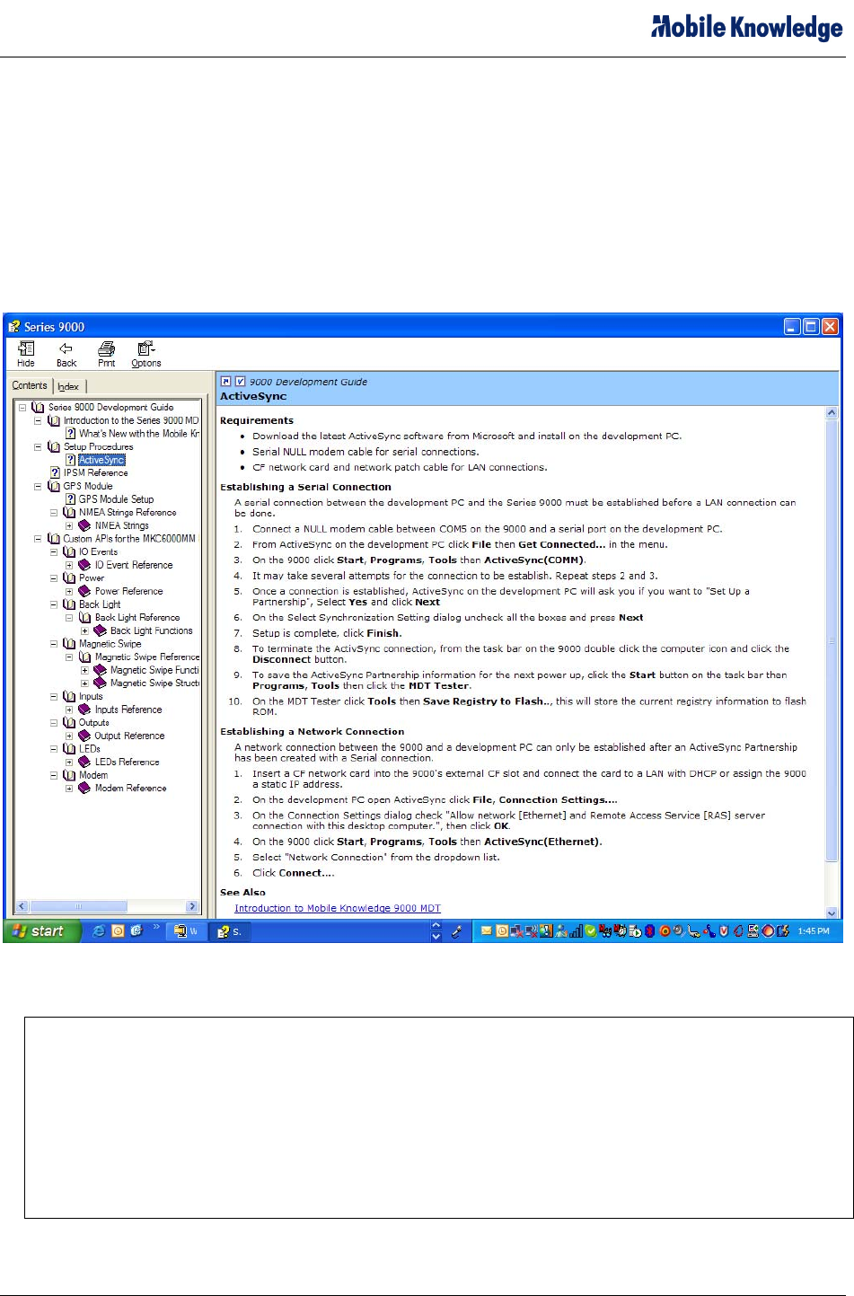
3.6.1 eMbedded Visual C++ Help
When installing the Series 9000 SDK platform, the help containing procedures and API call descriptions
are incorporated within the eMbedded Visual C++ help as shown in Figure 3-3.
Figure 3-3 – Series 9000 SDK Help File
Note: The Series 9000 Mobile Data terminal contains two types of embedded memory. The
MDT has 64MB of RAM, and 64MB of Flash memory. The SDK developer has approximately 40MB
of available space in the Intel Persisten Memory Manager section of Flash. This Intel Strata Flash
component is rated for a minimum 100K erase cycles per block. The Intel PSM software also
provides a measure of write-leveling to extend the lifecycle of this component.
Typically, software implementation utilizes RAM memory (not limited in this fashion) for frequent non-
persistent storage. Flash Memory should only be used to store minimum amounts of data as required
to survive a restart. When engineering an application the usage of flash memory must be carefully
calculated and accounted for during the design phase.
9000 SDK Getting Started - A5.doc © Mobile Knowledge Corp. Page 13 of 17

Series 9000 SDK Getting Started Manual
9000 SDK Getting Started - A5.doc © Mobile Knowledge Corp. Page 14 of 17

Series 9000 SDK Getting Started Manual
4. OPTIONAL PUBLIC DATA RADIO MODEM
The Series 9000 is available with an optional internal Wavecom Q2406/Q2426 GPRS modem module.
The following Series 9000 model numbers include the internal modem:
• 360-24wx-y1z – European Configuration (900/1800 MHz)
• 360-24wx-y2z – North American Configuration (850/1900 MHz)
Where w, x, y, and z can be any integer.
In these configurations, the following safety precautions should be noted and taken:
4.1 Safety Notification:
To comply with RF safety requirements, please maintain a separation distance of 20cm from the antenna
located on the exterior of the vehicle.
Modifications not expressly approved by ,Mobile Knowledge Corp. could
void the user's authority to operate the equipment.
NOTE: This equipment has been tested and found to comply with the limits for a
Class B digital device, pursuant to Part 15 of the FCC Rules. These limits are
designed to provide reasonable protection against harmful interference in a
residential installation. This equipment generates, uses and can radiate radio
frequency energy and, if not installed and used in accordance with the
instructions, may cause harmful interference to radio communications. However,
there is no guarantee that interference will not occur in a particular installation.
If this equipment does cause harmful interference to radio or television reception,
which can be determined by turning the equipment off and on, the user is
encouraged to try to correct the interference by one or more of the following
measures:
-- Reorient or relocate the receiving antenna.
-- Increase the separation between the equipment and receiver.
-- Connect the equipment into an outlet on a circuit different from that to which the receiver is
connected.
-- Consult the dealer or an experienced radio/TV technician for help.
9000 SDK Getting Started - A5.doc © Mobile Knowledge Corp. Page 15 of 17

Series 9000 SDK Getting Started Manual
5. ADDITIONAL RESOURCES
Microsoft Windows eMbedded page:
http://msdn.microsoft.com/embedded/
Microsoft Windows CE page:
http://www.microsoft.com/windowsmobile/resources/downloads/default.mspx
9000 SDK Getting Started - A5.doc © Mobile Knowledge Corp. Page 16 of 17
Series 9000 SDK Getting Started Manual
9000 SDK Getting Started - A5.doc © Mobile Knowledge Corp. Page 17 of 17
6. SERIES 9000 CABLING
6.1 Cable - Series 9000 Power (PN 850-0231-000)
6.2 Cable – Series 9000 COM/IO (PN 850-0230-000)
6.3 Cable – Series 9000 COM Extender (PN 850-0233-000)