Mobiletron Electronics LF004 LF Controller User Manual
Mobiletron Electronics Co., Ltd. LF Controller
User manual

Table of Content
Content
1. Product Introduction 1
2. Installation of Transmitter 1~6
2
.1
Receive ID Mode
---
LF
004
setting for clamp
transmitter
2
.2
Start to install TX012
2
.
3
S
p
e
c
i
a
l
s
e
t
u
p
:
Manual
I
nput
N
ew
T
ransmitter ID
C
ode
3. Limit Warranty 7~8
3.1 Warranty Service
3.2 What Are Not Covered
4. Thing to Notice 8
5. Technical Specification 9
1
1ǵ
ǵǵ
ǵ
Product Introduction
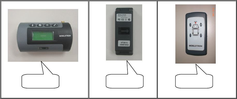
LF004 is a controller, used to set transmitter ID of every wheel to LCD screen of digital
receiver.
Take the models of TX014 and RX003 to help explain how to use LF004 completely.
TX014 : a kind of transmitter
RX003 : a kind of LCD screen of digital receiver
TX014 contains highly accurate sensors to detect tire pressure and temperature.
Before installing TX014 on the Wheel Rim, receive and set TX014 ID Mode to RX003
by using LF004. RF modules send data via radio wave to RX003 placed in driver’s
cabin. when the vehicle is in motion,TX014 starts to detect pressure and temperature
automatically. Pressure and temperature data will be showed on RX003. If the
pressure and temperature go wrong, the driver will be warned with LCD backlight,
beep, and flashing numbers. Therefore, the driver can take action immediately.
2ǵ
ǵǵ
ǵInstallation of Transmitter
Attention:
Transmitters must be installed by professional technicians. The technicians have to
follow the installation guide step by step to install transmitters correctly.
Following tools and instructions are for technicians, not for end users.
Tire Changer
Wheel Balancer
Pliers
Other Hand-tools
RX003 TX014 LF004
2
2.1 Receive ID Mode---LF004 setting for clamp transmitter
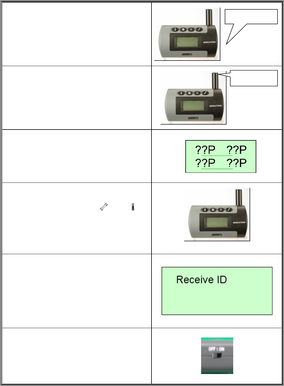
1.
Put the 12DCV POWER CABLE to the
Receiver.
2.
Tighten the Antenna.
3.
Check if the LCD of the Receiver shows
“??P“.
4.
Simultaneously press button and for
more than 2 seconds to enter “Receive ID
Mode”.
5.
Check if the LCD of the Receiver shows.
“Receive ID“.
6.
Turn on the LF004.
Antenna
Power Plug
3
7.
Select one of the tires you want to set up.
Ɂ
ɁɁ
ɁNOTE:
The signal active distance of LF004 is 0.3m.
8.
Put LF004 near the transmitter at least 30mm.
9.
We suggest that installing the tire after setting.
10.
Ɂ
ɁɁ
ɁIMPORTANT:
When setting, please keep other transmitter
away from the setting transmitter at least 1m.
Ɂ
ɁɁ
ɁNOTE:
If you are not sure it receives the signal or
not please do it again or refer to Item ˅ˁˆʳ
ϘManual input new transmitter ID codeϙʳ
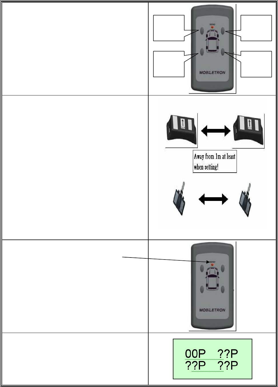
11.
Push the button of “ENTER”
And the “SEND” LED will flash.
12.
Then the receiver will receive the signal and
show “00P” (No pressure)
Left-
Front
Left-
Rear
Right-
Front
Right-
Rear
4
13.
If the transmitter is already in the tire, you will
see the tire pressure.
14.
Ɂ
ɁɁ
ɁIMPORTANT:
If you want to check the tire as usual ,you
may push any button of LF004 and RX003 will
show the pressure(The signal active distance
of LF004 is 0.3m )
15.
After setting, push button the LCD of the
Receiver shows “Receive ID Cancel”
16.
As the voltage is below 2.3V, pushing any
button will make the “SEND” LED flash every
4secs.
NOTEǺ
ǺǺ
ǺThe value above is for reference.
2.2 Start to install TX012
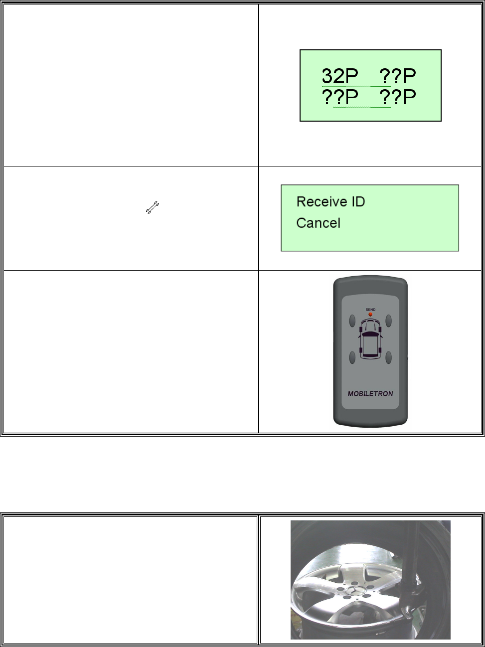
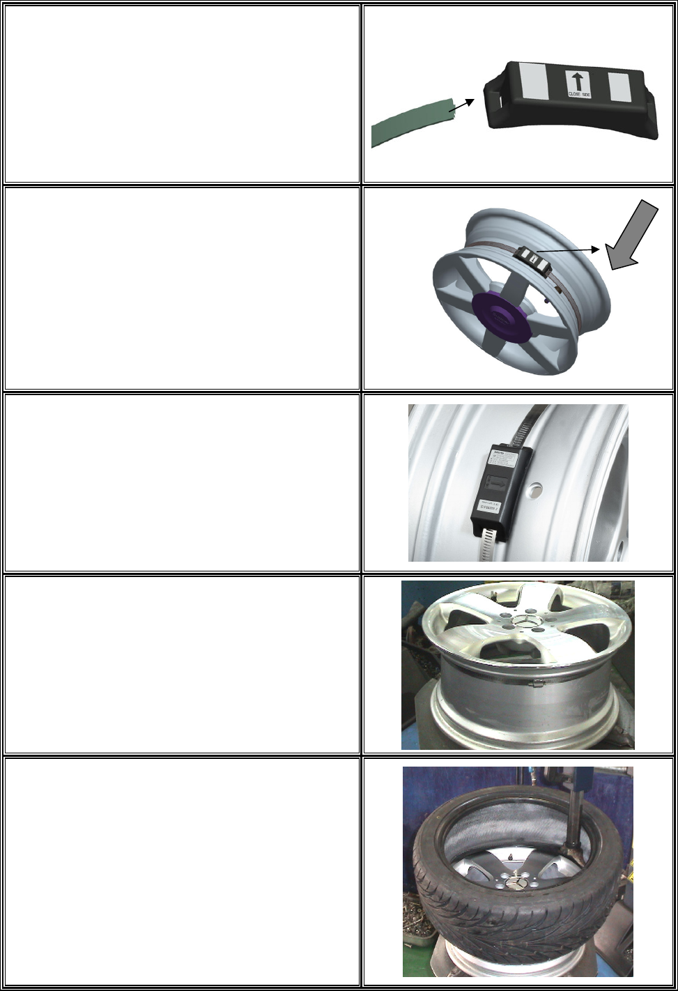
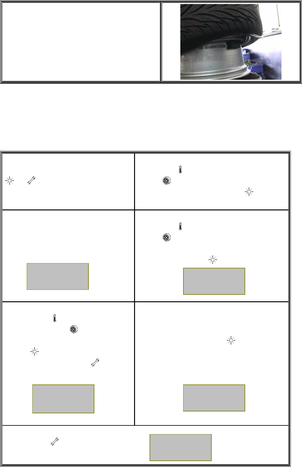
1.
Please follow the standard procedures to
dismount tire from rim.
5
2.
Install the clamp.
Ɂ
ɁɁ
ɁIMPORTANT
Before install the clamp, please check if
the ID of the transmitter had been set up .
!
3.
Make sure arrow on the transmitter point to
rubber valve side.
!
4.
Put the transmitter in the lowest area of the rim
or drop center, and beside valve. Tighten the
strap.(Torqre must over 0.35 kfg-m)
Suggestion:
Place lock of strap opposite to transmitter
mounting position for better tire rebalancing. !
5.
Cut excess strap off to approximately one
1nch (25mm); blunt sharp cutting edge.
!
6.
Wheel Balancing is required after transmitter
installation.
!
6
7.
Reverse the above steps to remove a
transmitter.
Suggestion:
Tell technician that you have installed TPMS
before he changes the tire. !
2.3 Special set up : Manual input new transmitter ID code
(Please contact with us)
1.
Simultaneously press button
and for more than 2 seconds to
enter “Special Set Up Mode”.
2.
Use button (act as downward button) and
button (act as upward button) to select
“New ID Input” settingǹPress button to
confirm.
3.
LCD Display will showǺ
4.
Use button (act as downward button) and
button (act as upward button) to move
ʈ
ʈʈ
ʈ
cursor
to select the tire location for ID
inputǹPress
button to confirm.
5.
Use button (act as downward
button) and button (act as upward
button) to select a number ǹPress
button to confirm then move to
the next numberǹPress button to
cancel.(The ID below is for reference )
6.
Double check input ID number to ensure it is
identical to that on the Label of
new
TransmitterǹPress button to confirm and
complete the setting. Then install the
transmitter in the associated tire
7.
Press button againǹ
LCD Display will return as initial display.
New ID
Input ʈ
ʈʈ
ʈ
01 02
03 04
IDΚ5B5B
5888
OK
32P
32P
32P 32P
7
3. Limit Warranty
Mobiletron, hereby warrants that this Mobiletron wireless tire pressure moni
Mobiletron, hereby warrants that this Mobiletron wireless tire pressure monitoring
system shall be free from material defects in workmanship and/or materials until
the expiry of twelve months from its purchase by the end user, EXCEPT WHERE
any such defect has been caused by: Improper or non-normal use, Improper
installation, contacts with any corrosive or otherwise harmful substance, any other
acts or omission not sanctioned by the User Manual.
Mobiletron warrants the wireless tire pressure monitoring system product for
twelve months from the end user purchase date under normal operation
condition, which is free from manual improper operation, improper
installation or any casualty.
Mobiletron’s sole obligation shall be to repair or replace the defective product
at no charge to the original owner.
Mobiletron warns the user or driver of the driving safety by the limited
warning signal range, and does not protect or take the responsibility of the
user’s or driver’s safety directly.
In no event will Mobiletron be liable for any direct, indirect, special, incidental
or consequential damage, including loss of profit, loss of savings, or any
other damages caused by product, or its documentation, or failure of the
product to perform, even if Mobiletron has been advised of the possibility of
such damages.
3.1 Warranty Service
(1) The above warranty will be honored by the retailer from which it was purchased,
provided that the owner can provide dated proof of purchase.
(2) In the event that any defect in the unit is covered by the above warranty,
Mobiletron will replace the affected components free of charge, shipping prepaid.
The owner shall be responsible for any labor and installation costs incurred in
removing the defective parts and/or installing the replacement.
(3) The retailer shall at Mobiletron’ cost send any unit which is defective as described
in the above warranty to Mobiletron at No.39, Sec 3, Chung-Ching Rd., Ta-Ya,
Taichung Hsien, Taiwan 428.
8
3.2
This Limited Warranty Provided by Mobiletron Does Not Cover
(1) Product that have been subjected to abuse, accident, alteration, modification,
tampering, negligence, misuse, faulty installation, lack of reasonable care,
improper transportation, repair or service in any way that is not authorized by
Mobiletron.
(2) Any damage attributable to fire, flood, lightning strike or act of God.
(3) This limited warranty coverage will exclude the package material and user
manual.
(4) The damage caused from benzene, alcohol or any corrosive cleaner.
(5) Any repair should implement in Mobiletron by returning from the Mobiletron
authorized retailer. Any repair without authorization will be excluded from
the warranty.
4. Things to Notice
Be sure to keep record of the Transmitter ID number for each of the corresponding
four tires on the last page. Because next time if the original Transmitter is replaced by a
new one, inputting the original Transmitter ID number to the new one should be a must.
Temperature Compensated Pressure Readings :
When a tire heats up, caused by long duration of driving or braking, the air pressure
inside the tire can also be expected to increase, e.g. tire temperature increases 20ʚ
to 30ʚ may lead to 3psi to 6psi pressure increment.

9
5. Technical Specifications
5.1 Operation Condition
˗ ˸ ̆ ˶ ̅ ˼ ̃ ̇ ˼ ̂ ́ ʳ ˩ ˴ ˿ ̈ ˸ ʳ ˔ ˶ ˶ ̈ ̅ ˴ ˶ ̌ ʳ ˨ ́ ˼ ̇ ̆ ʳ
ˀ˅˃ʳ̑ ʳʾ ˉ ˃ʳ ̈́ʳ ˆʳ кʳ
ˢ ̃ ˸ ̅ ˴ ̇ ˼ ́ ˺ ʳ˧ ˸ ̀ ̃ ˸ ̅ ˴ ̇ ̈ ̅ ˸ ʳ ˀˇʳ̑ ʳʾ ˄ ˇ˃ʳ ̈́ʳ ˈʳ лʳ
ˀ˅˃ʳ̑ ʳʾ ˉ ˃ʳ ˀʳ кʳ
˦ ̇ ̂ ̅ ˴ ˺ ˸ ʳ˧ ˸ ̀ ̃ ˸ ̅ ˴ ̇ ̈ ̅ ˸ ʳ ˀˇʳ̑ ʳʾ ˄ ˇ˃ʳ ˀʳ лʳ
ˢ ̃ ˸ ̅ ˴ ̇ ˼ ́ ˺ ʳ˛ ̈ ̀ ˼ ˷ ˼ ̇ ̌ ʳ ˃ʳ̑ ʳ˄ ˃˃ʳ ˀʳ ʸʳ
5.2 Radio Transmitter
˗ ˸ ̆ ˶ ̅ ˼ ̃ ̇ ˼ ̂ ́ ʳ ˩ ˴ ˿ ̈ ˸ ʳ ˨ ́ ˼ ̇ ̆ ʳ
ʳ
˖ ˸ ́ ̇ ̅ ˴ ˿ ʳ˙ ̅ ˸ ̄ ̈ ˸ ́ ˶ ̌ ʳ ˄ ˅ˈʳ ˞˛ ̍ ʳ
˦ ˴ ̀ ̃ ˿ ˼ ́ ˺ ʳ˥ ˴ ̇ ˸ ʳ ˇʳ ˦ ˸ ˶ ̂ ́ ˷ ʳ
˥ ˴ ́ ˺ ˸ ʳ ˆ˃ʳ ˖ ̀ ʳ
5.3 General Specification
˗ ˸ ̆ ˶ ̅ ˼ ̃ ̇ ˼ ̂ ́ ʳ ˩ ˴ ˿ ̈ ˸ ʳ ˨ ́ ˼ ̇ ̆ ʳ
ʳ
˗ ˼ ̀ ˸ ́ ̆ ˼ ̂ ́ ̆ ʳ ˄ ˄ ˊ ˁˈʽ ˈˊ ˁˇʽ ˄ ˈˁ˅ˊ ʳ ̀ ̀ ʳ
ʳ
˪ ˸ ˼ ˺ ˻ ̇ ʳ ˋ ˃ʳ ˚ ̅ ˴ ̀ ʳ
ʳ
5.4 Power
˗ ˸ ̆ ˶ ̅ ˼ ̃ ̇ ˼ ̂ ́ ʳ ˧ ̌ ̃ ˸ ʳ ˩ ˴ ˿ ̈ ˸ ʳ ˨ ́ ˼ ̇ ̆ ʳ
ˣ ̂ ̊ ˸ ̅ ʳ˦ ̂ ̈ ̅ ˶ ˸ ʳ ˟ ˼ ̇ ˻ ˼ ̈ ̀ ʳ˕ ˴ ̇ ̇ ˸ ̅ ̌ ʳ ˆˁˉ ʳ ˩ ˷ ˶ ʳ
˕ ˴ ̇ ̇ ˸ ̅ ̌ ʳ˟ ˼ ˹ ˸ ʳ ˀʳ ˅ʳ ̌ ˸ ˴ ̅ ʳ
Manufacturer: Moniletron Electronic ,Inc.
Address : No.39, Sec 3, Chung-Ching Rd., Ta-Ya, Taichung Hsien, Taiwan 428
Telephone : +886-4-25683366
Fax : +886-4-25673069
Web Site: http://www.more.com.tw
FCC Caution:
1.The device complies with Part 15 of the FCC rules. Operation is subject to the following
two conditions:
(1) This device may not cause harmful interference, and
(2) this device must accept any interference received, including interference that may
cause undesired operation.
2.This device and its antenna(s) must not be co-located or operating in conjunction with
any other antenna or transmitter.
3. Changes or modifications to this unit not expressly approved by the party responsible
for compliance could void the user authority to operate the equipment.