Mobiletron Electronics TX014 Tire Pressure Monitoring System User Manual
Mobiletron Electronics Co., Ltd. Tire Pressure Monitoring System
User Manual

Installation and Operating Instructions
for
Tire Pressure Monitoring System
Model No. :TX014
Contents
1. System Introduction
2. Safety Notices
3. Applicable Vehicles
4. Operation and Installation of Wireless Tire Pressure Monitoring System
4.1 Installation and Mounting of Transmitter.
4.2 Removing Tire with the transmitters inside.
5. Limit Warranty
5.1 Warranty Service
5.2 This Limited Warranty Provided by Mobiletron Does Not Cover
6. Technical Specifications
格式化: 項目符號及編號
格式化: 項目符號及編號
格式化: 項目符號及編號
格式化: 項目符號及編號
1. System Introduction
(1) TX014 is a wireless tire pressure monitoring system with sensors and transmitters
mounted in each tire and set by LF Controller. Highly accurate sensors collect tire
pressure and temperature data which is transmitted to a Digital Display Receiver.
(2) The System monitors the tire data with a LCD display which informs the driver of
the condition of the tires while driving. The Digital Receiver will immediately alert
with a beeping sound, a bright yellow LED and the backlight of the LCD when tire
pressure and/or temperature are outside of factory-preset critical limits. The
wireless tire pressure monitoring system will alert the driver to the unsafe tire or
temperature condition and thereby reduce the possibility of an accident.
2. Safety Features
(1) The System is designed to measure and display active data, i.e. pressure and
temperature, in tires, and provides a warning when the System detects tire pressure
and/or temperature is above or below preset critical limits. It is the driver’s
responsibility to react to a warning. Abnormal tire pressure and temperature must be
checked and brought back to within the preset safe limits to avoid dangerous driving
conditions.
(2) This product must be properly installed and programmed by qualified personnel
according to this User Manual.
3. Applicable Vehicles
This system is suitable for use on passenger cars and trucks of 4 wheels.
4. Operation and Installation of Wireless Tire Pressure
Monitoring System
4.1 Installation and mounting of transmitter Caution:
The transmitter devices should be installed by qualified technician。They following
installation procedures must be followed。This will ensure that the transmitters are
properly installed and undamaged。
Some tools and instructions referenced in this user’s manual are only available
and tire outlets and are not available to the consumer 。
Tools Required:
(1)Tire Changing Equipment。
(2)Tire Balancing Equipment。
(3)Metal Cutter。
(4)Torque Wrench。
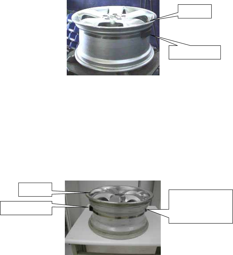
Mounting the Tire with Transmitter on Wheel Rim
1. Fasten Transmitter on the Wheel Rim
1st. Pass Clamping Strap through Transmitter。
2nd. Position the Transmitter in the lowest area of the concave center
well near the valve。
Note:It is recommended that the location of each transmitter be recorded to
avoid possible damage when tires need to be removed。
3rd. Attach the Clamping Strap end to the clamp by advancing the
Worm Gear Clamp with a socket driver or screwdriver ;tighten the
Clamping Strap until secured.。
Note:Position Worm Gear Clamp opposite to Transmitter for better tire
rebalancing。
4th. Cut excess Clamping Strap off to approximately one inch (25mm)
from Worm Gear Clamp with a Cutter;remove burrs from Clamping
Strap end。
Valve
Transmitter
Position Worm Gear
Clamp Opposite to
Transmitter
Valve
Transmitter
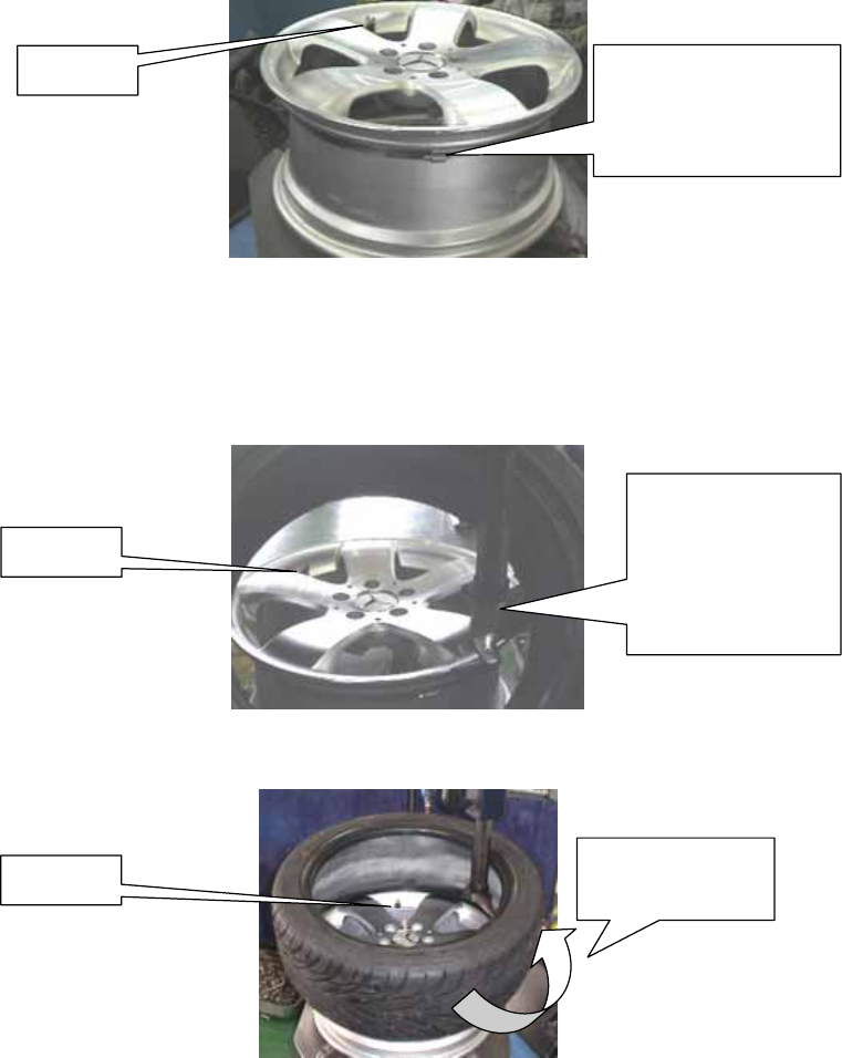
2. Assemble Tire
1st. Place tire under Transmitter as shown below。
2nd. Use auto-install machine to install the lower-side of tire onto rim。
3rd. Place the upper-side of tire onto rim。
Notice:turn slowly by machine to force down the wall of tire。
Position Worm Gear
Clamp Opposite to
Transmitter
Valve
Valve
Place Tire
Changing
Machine’s Lever to
the Opposite Side
of Valve
Turn in This
Direction Slowly
Valve
4th. Install whole tire to the wheel。
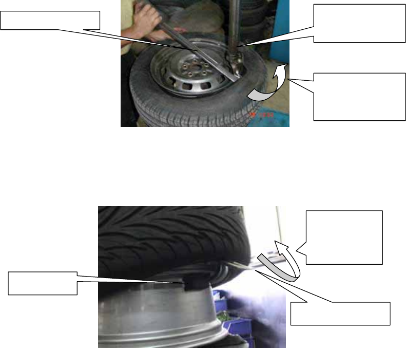
4.2 Removing tire with the transmitter Inside
Caution::
The transmitter devices should be removed by a qualified technician。The removal
directions must be followed to ensure that the transmitters are undamaged。
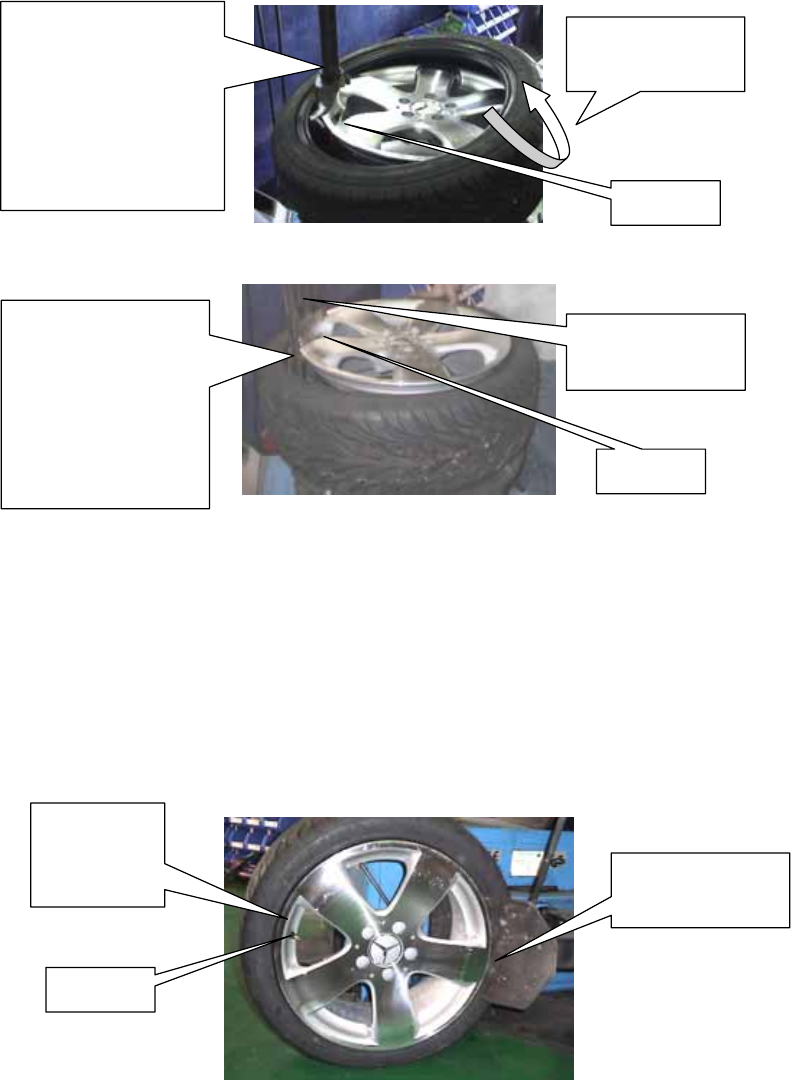
1. Remove Valve Cap and Deflate Air Completely
Screw valve cap out of valve and let air discharge completely;remove
balancing weight/s;press tire off the safety shoulder inside and outside。
Tire Changing
Machine’s Lever Has
to Come to a Stop
Before Valve to
Ensure It Won’t Touch
Nearby Transmitter
Valve
Turn in This
Direction Slowly
Valve
Tire Changing
Machine’s Lever
Place Tire Lever to
the Opposite Side of
Tire Changing Lever
(Contrasting to
Valve) to Protect
Nearby Transmitter
Location of
Transmitter
Within Tire
Valve
Tire Changing
Machine’s Lever
Caution: In order not to damage the transmitter,Tire Level should be placed in the
opposite side of valve。
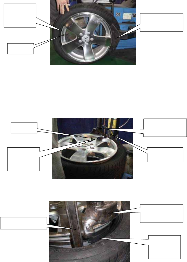
2. Removing the tire from the rim
1st. Place tire onto the installation machine;rub soapy water onto tire
bead and rim lip。
2nd. Place the machine Tire Lever on the tire bead and lift tire bead with
a manual Tire Lever over the installation head and pull tire away。
Location of
Transmitter
Within Tire
Valve
Tire Changing
Machine’s Lever
Tire Changing
Machine’s Lever
Manual Tire Lever
Location of
Transmitter
Within Tire
Valve Tire Changing
Machine’s Lever
Tire Lever
Location of
Transmitter
Within Tire
3rd. Utilize Manual Tire Lever,simultaneously with Tire Changing
Machine’s Lever,to pull the lower tire bead away from upper side of
wheel。
4th. Remove the Transmitter from the rim。
5. Limit Warranty
Mobiletron, hereby warrants that this Mobiletron wireless tire pressure monitoring
system shall be free from material defects in workmanship and/or materials until the
expiry of twelve months from its purchase by the end user, EXCEPT WHERE any
such defect has been caused by: Improper or non-normal use, Improper installation,
contacts with any corrosive or otherwise harmful substance, any other acts or
omission not sanctioned by the User Manual.
¾ Mobiletron’s sole obligation shall be to repair or replace the defective product at
no charge to the original owner.
¾ Mobiletron cautions the user or driver of the driving safety by the limited warning
signal range, and does not protect or take the responsibility of the user’s or
driver’s safety directly.
¾ In no event will Mobiletron be liable for any direct, indirect, special, incidental or
consequential damage, including loss of profit, loss of savings, or any other
damages caused by this product, or its documentation, or failure of the product to
perform, even if Mobiletron has been advised of the possibility of such damages.
Turn in This
Direction Slowly
Manual Tire Lever
Transmitter
Turn in This
Direction
Slowly
Manual Tire Lever Tire Changing
Machine’s Lever

5.1 Warranty Service
(1) The above warranty will be honored by the retailer from which it was
purchased, provided that the owner can provide dated proof of purchase.
(2) In the event that any defect in the unit is covered by the above warranty,
Mobiletron will replace the affected components free of charge, shipping
prepaid. The owner shall be responsible for any labor and installation costs
incurred in removing the defective parts and/or installing the replacement.
(3) The retailer shall at Mobiletron’ cost send any unit which is defective as
described in the above warranty to Mobiletron at No.39, Sec 3, Chung-Ching
Rd., Ta-Ya, Taichung Hsien, Taiwan 428.
5.2 This Limited Warranty Provided by Mobiletron Does Not Cover
(1) Products that have been subjected to abuse, accident, alteration, modification,
tampering, negligence, misuse, faulty installation, lack of reasonable care,
repair or service in any way that is not authorized by Mobiletron.
(2) Damage that occurs in shipment or due to an act of God.
6. Technical Specifications--Transmitter
Description Value Accuracy Units
Pressure Range 0 ~ 80 +/- 1 PSI
Rated Pressure 240 - PSI
-40 ~ +125 +/- 2 ℃
Operating Temperature -40 ~ +257 +/- 3 ℉
Operating Humidity 0 ~ 100 - %
6.1 Radio Frequency Transmitter
Description Value Units
Central Frequency 433.92 MHz
6.2 General Specification
Description Value Units
Sensor Sampling Rate 4 Second
Weight 38 Gram
6.3 Power
Description Type Value Units
Power Source Lithium Battery 3.6 Vdc
Battery Life - 7years
or
Over 2,000,000 km Year or km
6.4 LF Controller
Description Type Value Units
LF Setting 125 - KHz

Manufacturer: Moniletron Electronic ,Inc.
Address: No.39, Sec 3, Chung-Ching Rd., Ta-Ya,
Taichung Hsien, Taiwan 428 Fax: +886-4-25673069
Web Site: http://www.more.com.tw
1. The device complies with Part 15 of the FCC rules. Operation is subject to
the following two conditions:
(1) This device may not cause harmful interference, and
(2) this device must accept any interference received, including interference
that may cause undesired operation.
2.FCC RF Radiation Exposure Statement: The equipment complies with FCC
RF radiation exposure limits set forth for an uncontrolled environment. This
equipment should be installed and operated with a minimum distance of 20
centimeters between the radiator and your body.
3. This device and its antenna(s) must not be co-located or operating in
conjunction with any other antenna or transmitter.
4. Changes or modifications to this unit not expressly approved by the party
responsible for compliance could void the user authority to operate the
equipment.