Mobilicom MCU-100 Ad-Hoc Wireless Mobile Communication Unit enabling broadband connectivity of data, voice and is based on 4G LTE technology - This device can be powered only via battery. User Manual manual
Mobilicom ltd. Ad-Hoc Wireless Mobile Communication Unit enabling broadband connectivity of data, voice and is based on 4G LTE technology - This device can be powered only via battery. manual
manual

MC-EMA
General Description and
Operational Manual for MCU-100
Mobilicom LTD
Hametzoda 31, Azor -Israel
Phone : +972-77-7103060 - Fax : +972-77-7103060 - www.mobilicom.com

MC-EMA Product Description and Operational Manual
Page : 2 / 22
DOCUMENT Information
Date
Ver
sio
n
Author(s)
Referen
ce
Distributi
on
Comments
12-3-12
0.1
Gilad Yam
Internal
Basic Template
2-4-12
0.2
Tomer Hot
Internal
2-4-12
1.0
Gilad Yam
customers
23-8-12
1.1
Gilad Yam
Customers
10-10-12
1.2
Gilad Yam
customers
21-10-12
1.3
Gilad Yam
customers

MC-EMA Product Description and Operational Manual
Page : 3 / 22
Contents
1 GENERAL ................................................................................................................................ 5
2 APPLICABLE PRODUCTS ..................................................................................................... 6
3 SETTING UP THE SYSTEM .................................................................................................... 7
3.1 INITIAL SETTINGS FOR AN MCU .............................................................................................. 7
3.1.1 Mobile PTP and PTMP system .................................................................................... 7
3.2 INSTALLATION ....................................................................................................................... 7
4 UNITS’ BRING UP ................................................................................................................. 12
4.1 MCU BRING UP .................................................................................................................. 12
5 INSTALLING AND CONNECTING THE MC-EMA ................................................................ 13
5.1 CONNECTING MC-EMA TO UNITS ........................................................................................ 13
5.1.1 Local MC-EMA connection ........................................................................................ 13
5.1.2 Remote MC-EMA connection..................................................................................... 13
5.2 MC-EMA SOFTWARE INSTALLATION .................................................................................... 14
5.2.1 Installing MC-EMA on a Laptop\PC ........................................................................... 14
5.3 UPDATING FIRMWARE TO AN MCU UNIT ............................................................................... 14
6 MC-EMA OVERVIEW ............................................................................................................ 15
6.1 MC-EMA ELEMENT MANAGEMENT APPLICATION ................................................................... 15
6.1.1 General Screen View ................................................................................................. 16
6.1.2 Link Monitor Screen View .......................................................................................... 18
6.1.3 Throughput Screen View ........................................................................................... 19
7 STANDARDIZATION ............................................................................................................. 20
7.1 DECLARATION OF CONFORMITY ............................................................................................ 20
7.2 PROFESSIONAL INSTALLATION ATTESTATION ......................................................................... 21

MC-EMA Product Description and Operational Manual
Page : 4 / 22
List of Figures
Figure 1: MCU-100 Unit Connectors (Front \ Back) ....................................................................... 10
Figure 2: MCU-100 Auxiliary Cable ............................................................................................... 11
Figure 4: Local connection of MC-EMA on PDA (Left) and Laptop\PC (right) ............................... 13
Figure 5: Remote connection over the air via another device (top) from NOC (down) .................. 13
Figure 6: MC-EMA General Screen View ...................................................................................... 16
Figure 7: Link Monitor Screen View ............................................................................................... 18
Figure 8: MC-EMA Throughput Screen View................................................................................. 19

MC-EMA Product Description and Operational Manual
Page : 5 / 22
1 General
This document aims to describe how to operate and monitor Mobilicom’s MCU’s and MC-HPA
units by using the MC-EMA including operational procedures and troubleshooting.

MC-EMA Product Description and Operational Manual
Page : 6 / 22
2 Applicable Products
Following are applicable products that are covered in this document, for more information please
refer to the specific product general description:
o MCU-100

MC-EMA Product Description and Operational Manual
Page : 7 / 22
3 Setting up the System
3.1 Initial settings for an MCU
3.1.1 Mobile PTP and PTMP system
1) A mobile point-to-point or P2MP system should contain at least 2 units.
2) In a system one MCU will be a master and at least one should be set as slave (P2P), or more
(P2MP).
3) Setting up a Master/Slave is done by burning the relevant ZIP file (Mobilicom will provide
both Master and Slave Files) (MC-EMA will support such configuration in the future)
4) After setting up Master/Slave the unit can be boot up and set up the rest of the parameters via
the EMA.
5) The rest of the parameters are set as a part of the profile customized for a client.
6) All these stages are typically done in the lab prior to shipment enabling easily plug-and play
by the customer (typically attenuators are connected to the RF ANT jacks in a basic unit
configuration without antenna). Nevertheless, this procedure can be done after installation as
well.
3.2 Installation
1) The MCU-100 can be installed in two ways:
o Installed using the 4 peripheral mounting holes – mainly used on large surfaces such as
walls, car top or ceilings. Schematics can be supplied by Mobilicom
o Installed using the back mounting holes via mounting arm (such as MT-120018/A) –
mainly used on poles. Schematics can be supplied by Mobilicom.
2) Antennas installation:
The antennas should be as close to the MCU-100 as possible and can be connected to it
directly into its ANT powers #1 and #2.
3) Cables should be chosen according to their attenuating (best ones should be chosen) and
flexibility (according to the path they pass through). Each cable should have TNC-Male
connector on one end and connector matching to the antenna on the other (most common are
N-Type Male/Female). Recommended cable standards can be supplied by Mobilicom.
7) Before powering up the MCU-100 the antennas should be connected to it (alternatively
attenuators can be connected to the RF ANT jacks for basic setups).

MC-EMA Product Description and Operational Manual
Page : 8 / 22
8) In order to verify that the MCU-100 is working (when there is no link) the MCU-100 can be
connected to a PC via Ethernet or RS232. When connected to a PC EMA can be run and get
some of the indications. The rest of the indications such as Link status, CINR, RSSI and
bandwidth are not relevant and will not be displayed.
9) Power Feed:
a. The device can be powered only via battery and not via AC/DC transformer.
b. The device can be marketed as battery powered only.
c. Communication and power harness can be supplied by Mobilicom as an auxiliary
cable, but can also be manufactured according to Mobilicom’s spec. The cable should
contain at least a 1GE and one power as a minimum, yet it is recommended that the
RS232 will be added as well. The Power line must contain a 4A fuse.
d. Voltage Regulation: 33% =(12-9)/9*100%
e. Battery Types that can be used:
Voltage: 12VDC
Max Current: 3A
Recommended AH: 24AH (for 8 hours operation)
f. Connecting the Battery:
Connect the Black Cable labeled -12VDC to the - of the Battery
Connect the Red Cable labeled +12VDC to the + of the Battery
g. Disconnecting the Battery:
Disconnect the Red Cable labeled +12VDC to the + of the Battery
Disconnect the Black Cable labeled -12VDC to the - of the Battery

MC-EMA Product Description and Operational Manual
Page : 9 / 22
Output power is conducted. This device must not be sold to the general public.
This device is not approved for use when being powered by the AC power lines either
directly, or indirectly, through another device.
Professional installation of this device is required.
The antenna(s) used for this device must be installed to provide a separation
distance of at least 20 cm from all persons, and must not be co-located or operating
in conjunction with any other antenna or transmitter except in accordance with FCC
multi-transmitter product procedures.
g.
MC-EMA Product Description and Operational Manual
Page : 10 / 22
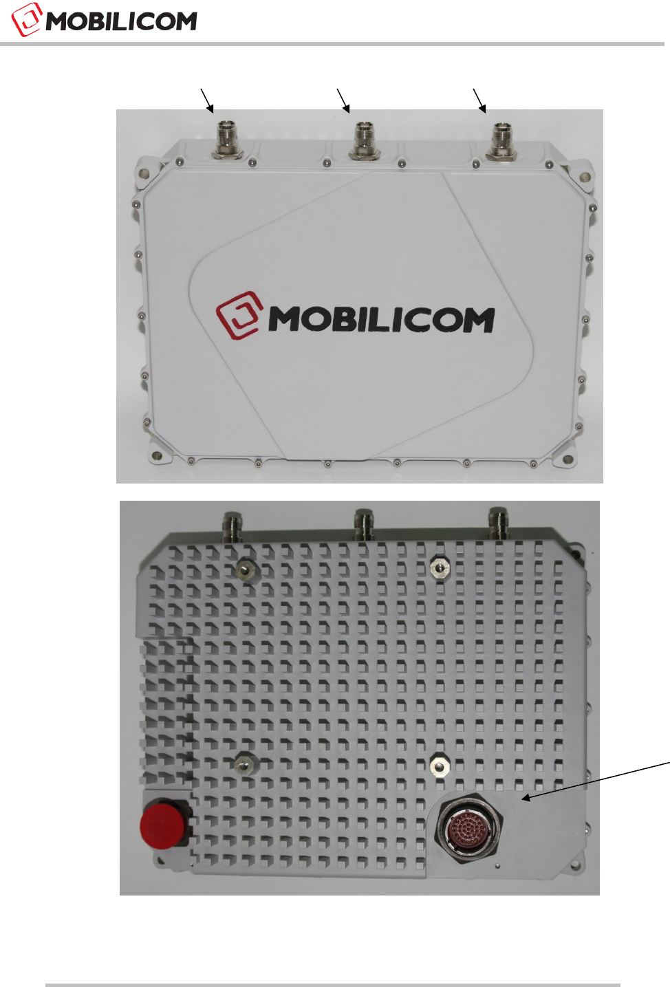
Figure 1: MCU-100 Unit Connectors (Front \ Back)
RF2
RF1
GPS
MAIN Cable
Power &
Ethernet to
Host (User PC,
Remote Cam,
Vessel Host
Control Unit)
MC-EMA Product Description and Operational Manual
Page : 11 / 22
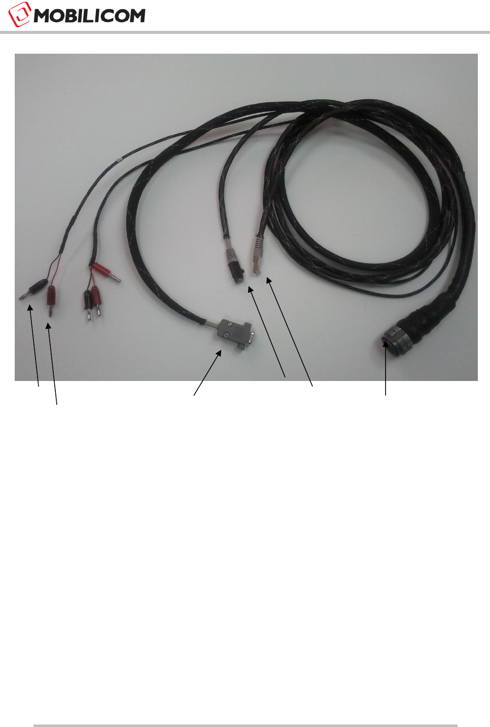
* Optional
Figure 2: MCU-100 Auxiliary Cable
(-) 12VDC
Serial*
(+) 12VDC
GigE
Main Unit
Connector
FE

MC-EMA Product Description and Operational Manual
Page : 12 / 22
4 Units’ Bring Up
4.1 MCU Bring Up
1) Once the MCUs are initialized as described in section 3.1, only power feed is needed for the
system. When powered up it starts its operation as a simple plug-and-play device
2) Firmware update is described in the MC-EMA section
MC-EMA Product Description and Operational Manual
Page : 13 / 22
5 Installing and Connecting the MC-EMA
5.1 Connecting MC-EMA to Units
This section describes the method of connection between the MC-EMA to a specific unit.
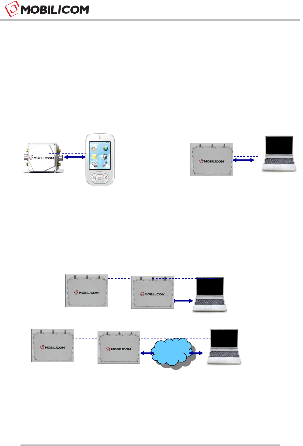
5.1.1 Local MC-EMA connection
The MC-EMA can be connected locally to an MCU unit as shown below:
Figure 3: Local connection of MC-EMA on PDA (Left) and Laptop\PC (right)
5.1.2 Remote MC-EMA connection
The MC-EMA can be connected over the air to a remote MCU unit as shown below:
Figure 4: Remote connection over the air via another device (top) from NOC (down)

MC-EMA Product Description and Operational Manual
Page : 14 / 22
5.2 MC-EMA Software Installation
5.2.1 Installing MC-EMA on a Laptop\PC
Following is the procedure to install the MC-EMA application on Laptop\PC:
1) Java Runtime Environment should be installed on your device.
2) Unzip the EMA package.
3) In order to run the EMA run the ema.bat file.
4) Use your EMA Manual to configure/use it.
5.3 Updating Firmware to an MCU Unit
Following are the steps for updating MCU firmware
1) Make sure that the MC-EMA is set to the box you wish to update.
2) Load the Zip file of the version you want to upgrade to.
3) Power down the MCU unit.
4) Power up the MCU unit.
5) Confirm the version number on the MC-EMA general screen.

MC-EMA Product Description and Operational Manual
Page : 15 / 22
6 MC-EMA Overview
6.1 MC-EMA Element Management Application
Mobilicom's MC-Element Management Application (MC-EMA) is optional, technical software tool
that runs on computer or portable device (PDA) and uses to test specific MCU node in the
network. It enables ease of configuration and maintenance and logs data for analysis,
configuration and maintenance purposes. This software can run on a computer or portable device
directly connected to a specific unit within the communications network or over the air-link to
remote devices via their IP address.
The MC-EMA enables:
Fault alarms for critical parameters
Configuration of the unit and its monitoring maintenance for online diagnostics
Performance of unit throughput and link status
Monitoring with online diagnostics
Logging data for offline analysis
The MCU-100 is a plug-and-play unit for the end-user, where the MC-EMA tool can be used by
Field Application Engineers (FAE’s), technical support and R&D Engineering on first installation
and maintenance purposes.
MC-EMA Product Description and Operational Manual
Page : 16 / 22
6.1.1 General Screen View
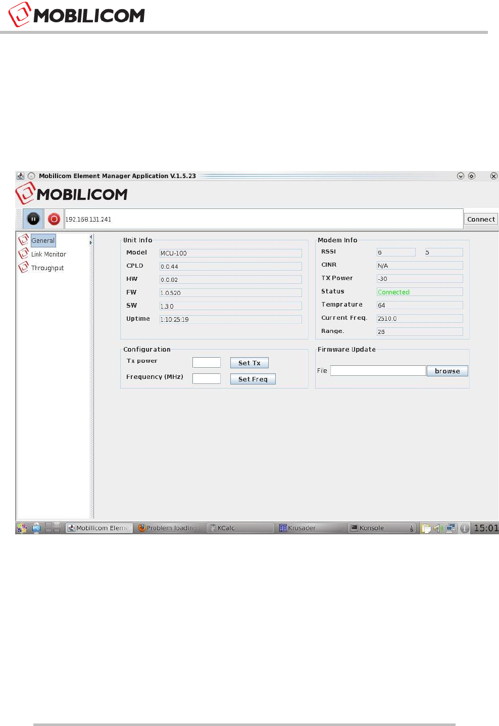
MC-EMA General Screen view (shown below) is the main EMA screen showing various unit info,
modem info configuration and firmware update info.
Figure 5: MC-EMA General Screen View

MC-EMA Product Description and Operational Manual
Page : 17 / 22
Following fields and parameters are shown in the general screen:
Unit Info field shows the following parameters:
Unit Model Type – MCU-100
CPLD – CPLD version
HW – Hardware version
FW – Firmware Version
SW – Software Version
Uptime – Amount of time the system is up and running
Modem Info field shows the following parameters:
6) RSSI – Received Power on each channel in dBm (-105 ÷ -20)
CINR – Signal To Noise Ratio for each channel in dB (0 ÷ 30)
Tx Power – Current Tx Power in dBm (updates each 5 seconds)
Status – Unit Status (Link Up/ Link Down)
Temperature – Unit temperature
Current Frequency – in MHz (will be updated after reboot if a freq was changed)
Range – in meters between 2 units
Configuration
Tx Power
Frequency in MHz
Firmware Update
Loading a ZIP file burns a new Software (and FPGA/Firmware) – Needs power down
in order to take effect
MC-EMA Product Description and Operational Manual
Page : 18 / 22
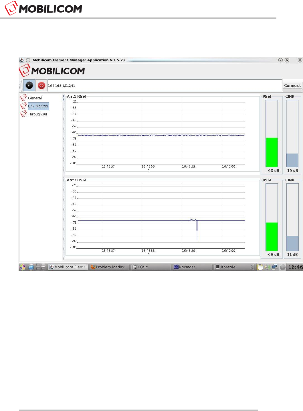
6.1.2 Link Monitor Screen View
The link monitor screen view shows the unit links performance as shown herein:
Figure 6: Link Monitor Screen View
Following graphics are shown in the link monitor screen:
Two sliding graphs of RSSI received power on each channel antenna
RSSI bar and value for each antenna channel
CINR bar and value for each antenna channel
MC-EMA Product Description and Operational Manual
Page : 19 / 22
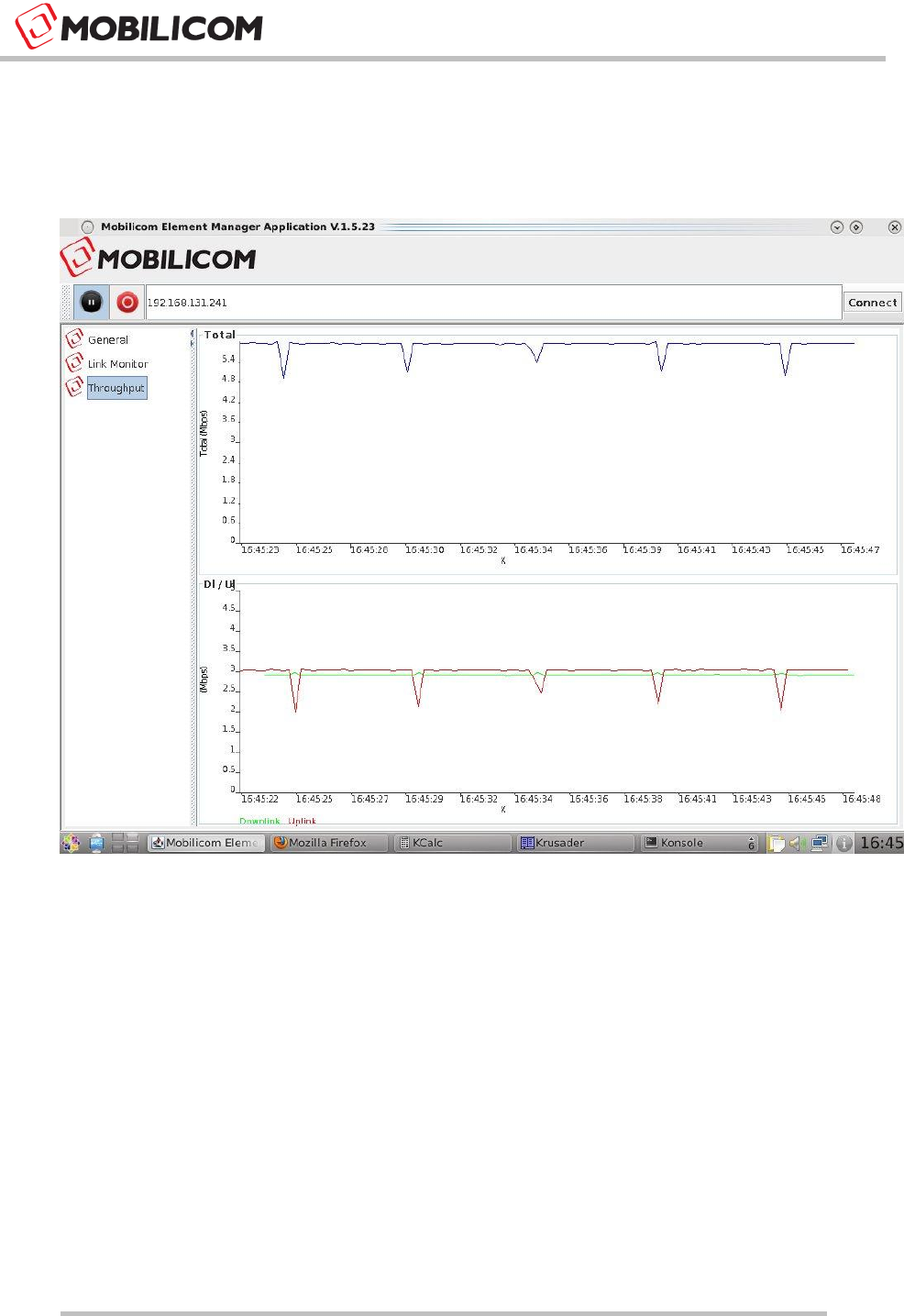
6.1.3 Throughput Screen View
The throughput screen view shows sliding graphs of Downlink and Uplink unit capacity in Mbps
as shown herein:
Figure 7: MC-EMA Throughput Screen View
MC-EMA Product Description and Operational Manual
Page : 20 / 22
7 Standardization
7.1 Declaration of Conformity
Manufacturer’s Name: MOBILICOM
Declares under our sole responsibility that the products:
Product Name: MCU-100
Conform(s) to the following standard(s) or other normative document(s):
FCC Part 15 Class A
FCC Part 15 Subpart C (15.247)
EN 300-328
This device complies with Part 15 of the FCC Rules. Operation is subject to the
following two conditions:
• The device may not cause harmful interference.
• This device must accept any interference received, including interference that may
cause undesired operation.
Le présent appareil est conforme aux CNR d'Industrie Canada applicables aux appareils
radio exempts de licence. L'exploitation est autorisée aux deux conditions suivantes :
(1) l'appareil ne doit pas produire de brouillage, et
(2) l'utilisateur de l'appareil doit accepter tout brouillage radioélectrique subi, même si le
brouillage est susceptible d'en compromettre le fonctionnement
This equipment has been approved for mobile applications where the equipment
should be used at distances greater than 20cm from the human body (with the
exception of hands, wrists, feet and ankles). Operation at distances less than 20 cm
is strictly prohibited.
Changes or modification to device not expressly approved by MOBILICOM LTD is
strictly prohibited and could avoid the user's authority to operate the equipment.

MC-EMA Product Description and Operational Manual
Page : 21 / 22
7.2 Professional Installation Attestation
MOBILICOM (the manufacturer) addresses the following items to ensure that the above
referenced equipment is professionally installed:
1. The MCU-100 will only be sold by MOBILICOM or one of its authorized dealers.
MOBILICOM and its authorized dealers will be under strict marketing control and will
only market and sell the MCU-100 to professionals.
2. Professional installation is required for the MCU-100 and will be performed only by
someone knowledgeable of its use.
3. MOBILICOM will ensure that the MCU-100 is only marketed and sold to professionals.
4. The MCU-100 is not sold to the general public and is sold only for industrial or
commercial use by professional installers.
5. List of approved antennas and power settings used shown on FCC grant. Installer
shall be responsible for ensuring that the proper antenna is employed so that the limits
in FCC Part 15 are not exceeded.
6. Power Feed:
a) The device can be powered only via battery and not via AC/DC transformer.
b) The device can be marketed as battery powered only.
c) Communication and power harness can be supplied by Mobilicom as an auxiliary
cable, but can also be manufactured according to Mobilicom’s spec. The cable
should contain at least a 1GE and one power as a minimum, yet it is
recommended that the RS232 will be added as well. The Power line must contain
a 4A fuse.
d) Voltage Regulation: 33% =(12-9)/9*100%
e) Battery Types that can be used:
Voltage: 12VDC
Max Current: 3A
Recommended AH: 24AH (for 8 hours operation)
MC-EMA Product Description and Operational Manual
Page : 22 / 22
f) Connecting the Battery:
Connect the Black Cable labeled -12VDC to the - of the Battery
Connect the Red Cable labeled +12VDC to the + of the Battery
g) Disconnecting the Battery:
Disconnect the Red Cable labeled +12VDC to the + of the Battery
Disconnect the Black Cable labeled -12VDC to the - of the Battery
Output power is conducted. This device must not be sold to the general public.
This device is not approved for use when being powered by the AC power lines either
directly, or indirectly, through another device.
Professional installation of this device is required.
The antenna(s) used for this device must be installed to provide a separation
distance of at least 20 cm from all persons, and must not be co-located or operating
in conjunction with any other antenna or transmitter except in accordance with FCC
multi-transmitter product procedures.