Shipways 2003 Users Manual Dapper Tom Instruction Book
2003 to the manual 4f1b5fc9-53ac-4c5e-bd1a-f3fe6b37973e
2015-02-09
: -Shipways -Shipways-2003-Users-Manual-557361 -shipways-2003-users-manual-557361 -shipways pdf
Open the PDF directly: View PDF ![]() .
.
Page Count: 24
Model Shipways Kit No. 2003
INSTRUCTION MANUAL
Manufactured by Model Shipways, Inc. • Hollywood, Florida
Sold by Model Expo, a division of Model Shipways, Inc. • www.modelexpo-online.com
Technical Characteristics
Scale: 5/32" = 1 ft.
Overall Length: 24"; Hull Length: 15-1/2"
Width: 9" (width of lower yard); Hull Beam: 4"
Height: 18" (top of main mast to bottom of keel)
MODELING THE
DAPPER TOM
✦ BALTIMORE CLIPPER PRIVATEER, 1815 ✦
MODELING THE
DAPPER TOM
✦ BALTIMORE CLIPPER PRIVATEER, 1815 ✦
Instructions prepared by Ben Lankford
Model prototype by Bob Werner ©2006, Model Shipways, Inc.

HISTORY
2
HISTORY
During the 19th Century, many Baltimore Clippers were granted privateering licenses by the US Government. Since
all commerce was subject to the legalized banditry of privateers, only a fast, well handled ship could be reasonably sure
of reaching its destination. Privateers like the Dapper Tom depended on their sailing abilities and fire power to prey on
foreign shipping and to escape the British men-of-war patrolling the high seas.
The Dapper Tom, an 8-gun topsail schooner, is to great extent, typical of Baltimore Privateers of a stormy decade when
ships were at the mercy of any stranger, and even armed ships were safe only in proportion to their nimbleness.
The plans of the Dapper Tom were developed in 1954 by John Shedd, the original owner of Model Shipways in Bogota,
New Jersey. The model is a reconstruction of a typical Baltimore Clipper. The model’s hull is based on Marestier’s draw-
ing No. 6 as taken off that vessel in stocks in 1814. Rigging is based on contemporary practice. Those wishing to study
the development of this type should consult Howard I. Chapelle’s book The Baltimore Clipper (See Bibliography).
While the plans are reproduced from the original, the kit has been updated and reissued by Model Shipways. These
new instructions are provided along with a more complete set of supplies for building the model. The fittings are now
cast from lead-free Britannia metal and some laser-cut wood parts added.
Brief History.................................................................2
Before You Begin ..........................................................3
How To Work With The Plans & Parts ........................3
What You’ll Need to Start Construction .......................3
Painting & Staining......................................................4
Stage A: Shaping the Pre-Carved Hull
1. Using the Templates .................................................4
2. Carving the Hull ......................................................5
3. Carving the Bulwarks ...............................................5
4. Carving the Transom & Counter..............................5
Stage B: Completing the Basic Hull Structures
1. Installing the Keel, Stem & Sternpost.......................6
2. Installing the Rudder................................................6
3. Drilling the Larger Holes in the Hull........................6
4. Holes to be Drilled as Work Progresses .....................6
5. Planking the Deck & Installing the Waterways.........6
6. Creating the Ladder Way Hole .................................7
7. Cutting Out the Gunports & Transom Ports............7
8. Installing Bulwark Stanchions & Cap Rail................7
9. Installing the Outboard Waterway Strip & Wale.......7
Stage C: Mounting the Hull
1. Mounting Board with Two Pedestals.........................7
2. Launching Ways .......................................................7
Stage D: Adding the Hull Details
1. General Notes...........................................................8
2. Transom Rail, Mouldings, Counter Detail,
& Main Sheet Traveler Rod ..........................................8
3. Catheads, Bulwark Sheaves, Cavils, Hawse Pipes, &
Gunport Lids ...............................................................8
4. Deck Bitts, Fife Rails, Pin Rails, Capstan, Galley
Funnel, Hatches, Ladder Way, Pumps, & Skylight ......9
5. Cannon ....................................................................9
6. Channels & Side Ladder...........................................9
Stage E: Mast & Spar Construction
1. Shaping the Masts ..................................................10
2. Assembling the Masts .............................................10
3. Shaping & Detailing the Spars................................11
4. Installing the Mast & Bowsprit Assemblies........11-12
Stage F: General Rigging Information................12-14
Stage G: Standing Rigging ..................................14-16
Stage H: Running Rigging ..................................17-22
Bibliography .............................................................22
Modeler’s Log............................................................23
Construction Stages & Table of Contents
Construction Stages & Table of Contents

3
Before You Begin
The Dapper Tom is an interesting model for
beginner and expert alike. This kit contains a
solid hull which has been machine-carved
from select, medium-hard, fine-grained bass-
wood. This style hull provides a quick and
easy lesson in the basic shapes and propor-
tions of hull design and helps to develop
woodworking skills. Although the exterior of
the hull has been carved close to the hull
lines as shown on the plans, further carving
is necessary for reasons of accuracy. (Carving
and finishing the hull to its final shape are
discussed in the instructions.)
Constructing the Dapper Tom model also
will provide you with the opportunity to
develop some scratch-building techniques.
During construction, you may want to sub-
stitute some of the kit fittings with your own
creations. By all means try them, especially if
you think you can improve the model.
If you are a beginner, completing this model
will prepare you for a more complicated
model such as the Pride of Baltimore II,
which is outfitted with a plank-on-bulkhead
hull. In the meantime, happy modeling!
Working with the Plans & Parts
Before starting model construction, examine
the kit and study the plans carefully. Familiar-
izing yourself with the kit will serve two
purposes. First, it will let you determine that
all parts have been supplied as listed. And sec-
ond, you’ll be surprised at how quickly
handling the parts allows you to better under-
stand the kit requirements. Try to visualize
how every part will look on the completed
model. Also, determine ahead of time what
must be done first. The instructions will help
you in this regard, but a thorough knowledge
of the plans at the outset is essential.
It is also suggested that all small fittings and
hardware be sorted into labeled boxes or
compartments to avoid loss during the
building process.
Two Plan Sheets and One Template Sheet
are provided:
1. Hull Templates - 1 sheet of heavy stock
2. Hull Plan-Sheet 1
3. Masting and Rigging Plan-Sheet 2
In addition, a set of sketches appears
throughout the instruction manual to further
illustrate the various stages of construction.
The Dapper T
om kit is manufactured to a
scale of 5/32” = 1’0” and matches the plans.
Consequently, most of the dimensions can
be lifted directly from the plans using a “tick
strip”. This is simply a piece of paper (a roll
of calculator paper tape works very well).
Mark a dimension from the plan onto the
tick strip and transfer it to the model.
The Dapper Tom model is designed to be dis-
played without sails. Much of the
reconstructed rigging was developed using
references from well-known books, such as
those by David Steel and Darcey Lever. (A
bibliography of references appears at the end
of this manual.) These texts provide many of
the details, but lack some of the unique char-
acteristics of the schooner rig. Consequently,
in designing the plans, additional references,
along with contemporary paintings and
etchings also were used. Even so, many
design decisions were made using good com-
mon sense: “If I were designing back then,
what would I have done?” There is always
doubt; no one can say for sure how the ship
was actually rigged.
The Dapper Tom kit is supplied with Britan-
nia metal, brass, as well as wooden fittings to
eliminate problems in making such parts
from scratch. Because the Britannia metals
contain no lead, there are no possible corro-
sion problems. Many of these fittings will
require final finishing before installing on
the model.
Before painting the cast-metal fittings, clean
them up by removing all the mold-joint flash.
To do this, use a No. 11 hobby blade to cut
the flash, then sand with fine sandpaper. It is
also suggested that you clean the fittings thor-
oughly with warm soapy water before applying
primer. Make sure they are rinsed thoroughly
and allowed to dry before painting.
What You’ll Need To Start
The following tools and supplies are recom-
mended for the construction process.
Modelers who have built before may have
their own favorites. Almost all are available
from Model Expo, a division of Model Ship-
ways, Inc., at www.modelexpo-online.com.
A. Knives and Saws
1. Hobby knife with No.11 blades
2. Razor saw (especially for cutting gun-
ports out of the bulwarks)
B. Files
Set of needle files
C. Sharpening Stone
Necessary to keep the tools razor sharp
D. Clamps
1. A few small C-clamps
2. Several wooden clothespins
3. Rubber bands
E. Tool Set
A small carving tool set and chisels for
shaping the hull.
F. Boring Tools
1. Set of miniature drills: #60 to #80
2. Larger bits for mast holes, bowsprit
hole, and hawse pipe holes
3. Pin vise
G. Miscellaneous
1. Tack hammer
2. Tweezers (a few)
3. Small fine pointed scissors
4. Miniature pliers
a. Small round b. Flat nose
5. Bench vise (small)
6. Soldering iron
a. Solder
b. Flux
Note: soldering is not essential for this par-
ticular model if the kit fittings are used.
7. Sewing thread (for seizings; other
rigging is supplied)
8. Beeswax block (for treating rigging lines)
9. 1/2” or 3/4” masking tape
10. Wire cutters (for cutting fine wire and
strip metal)
H. Sandpaper
Fine and medium grit garnet or aluminum
oxide sandpaper (#100 to #220 grit)
I. Finishing:
1. Paint brushes
a. Fine point for details
b. 1/4” to 1/2” flat square for hull
J. Supplies: (will be covered in detail in
the Painting & Staining section and
throughout instructions)
1. Paints
2. Primer
3. Stain and Varnish
4. White or Carpenter’s (yellow)
Wood Glue
5. Five-minute epoxy
6. Contact or model airplane acetate
cement
7. Cyanoacrylate (Super) Glue
Note about glues: White or Carpenter’s yel-
low wood glue will suffice for most of the
model. Five-minute epoxy provides extra
strength for gluing fittings. Because white or
yellow glues will tend to warp the scored-
sheet decking, use a contact cement or
model airplane type acetate cement. Cyano-
acrylate (Super) glue, called CA glue for
short, such as Zap is excellent for quick
adhesion and is ideal for dabbing onto a rig-
ging seizing to hold it in place. The best CA
glue for most applications is a medium vis-
cosity gap-filling type. The watery-thin type
is recommended only to fill a narrow crack
by capillary action. For CA glue, you can
also purchase a liquid accelerator such as Zip
Kicker. A spray or drop of the accelerator
will instantly cure the glue. This is handy to
eliminate clamping parts for long periods of
time and waiting for glue to harden.
Use CA glue with caution. You can easily
glue your fingers or eyelids together and the
fumes can burn your eyes. It would be a
good idea to have a bottle of CA debonder
on hand. This product will dissolve the glue
if you do get it on your body.

4
Painting and Staining
It may seem strange to begin an instruction
manual with directions for applying the fin-
ishes to the model. Not so! Much time and
effort can be saved and a more professional
result can be obtained if the finishing process
is carried out during construction. Proper
timing in application of finishes and the use
of masking tape to define painted edges
should eliminate unsightly glue marks and
splotchy stained surfaces. In the end, follow-
ing these general suggestions will be to your
advantage.
Paint Colors:
At the time of Dapper Tom, 1815, colors
were largely determined by economics. Reds,
yellows, and grays were cheap mineral colors,
hence more common. White lead was com-
ing into use but was still expensive.
A suggested color scheme for Dapper Tom
is as follows:
Hull Above the Waterline - Black with a
cream stripe at gunport level. Painting the
Wale strip cream will do the trick.
Hull Bottom Below Waterline - Pale
Green to represent weathered copper. A thin
wash of black over the green will enhance
the weathered look but do not overpower
the green.
Deck Planking - Natural or a light tan stain
such as pine.
Inside Bulwarks (including the stan-
chions) , Waterways, Top of Skylight,
Hatch Gratings, Transom Cap Rail & Side
Mouldings, Inside Transom & Counter -
Light Buff
Hatch Coamings, Galley Funnel Coam-
ing, Pin Rails, Bitts, Channels, Catheads,
Skylight Sides, Gun Carriages, Anchor
Stock - Dark Reddish Brown (preferred) or
White (second choice)
Stern Decoration - Gold stars.
Masts & Spars - Pine Stain.
Mast Doublings, Tops, Rudder Tiller,
Galley Funnel, Gaff Jaws, Bowsprit Cap,
Bulwark Cap Rails, & Gun Carriage
Wheels - Black.
Cannon Barrels & Anchors - Iron Black.
Capstan - Black top & Dark Reddish
Brown barrel.
Paint:
Use a flat-finish paint. Model Shipways line
of acrylic paints are available in the recom-
mended colors. You may also purchase an
already assembled Dapper Tom paint kit
from Model Expo
at www.modelexpo-online.com.
Primer:
Use a grey primer (one is provided with the
Model Expo Dapper Tom paint kit.) The grey
color will highlight sanding scratches and
other defects better than white primer. Prime
all woodwork to be painted, and prime all
metal fittings. Lightly sand the primed
items. Use a spackling compound such as
Pic-n-Patch brand to fill any scratches and
defects, then re-prime.
Stains & Finishes:
For natural finished wood, use a protective
coating after staining, such as low-sheen
polyurethane varnish. You can also use an
oil-resin mix like the ones sold by Model
Expo or Minwax.
For the deck and spars, Model Expo stain or
Minwax can be used. These are a combina-
tion stain-finish that will provide a light tone
to the wood. The deck plank scores can be
darkened with any dark color to simulate
caulking. It would be best to first varnish the
surface, wiping the dark color into the
scores, the wipe the surface of the planks
clean. You can also run a sharp No. 2 pencil
down each groove, then varnish.
The staining of all wood parts should be
done before gluing, especially if any CA glue
is used. Glue will leave ugly white areas in
the finish, and the stain will not penetrate
these areas.
Brushes & Procedures:
Use good quality soft sable or synthetic hair
artist’s brushes. A small pointed brush is
good for details. For the main hull areas, use
a 1/4" to 1/2" flat brush.
Before painting, clean the model with a tack
rag. Apply your paint in smooth and even
strokes, overlapping them as you go. Thin
the paint enough to eliminate brush strokes,
but not run. You will need three or four
coats of the light colors to cover the grey
primer and maybe only two coats of the
dark. Check your finish between coats and
sand and add spackle as necessary to get rid
of any blemishes.
You will be told how to mark the waterline
location in Stage A. At this line, and any-
where else two colors meet, use masking
tape. Electrician’s black plastic tape or any of
the hobby tapes made of plastic film are
ideal. They leave a nice edge and are not
overly sticky. Do not use drafting tape unless
it is Chart-pak brand. The edges are some-
what wrinkled and paint may run under
them. A good trick; seal the edge of masking
tape with a clear flat finish and let dry thor-
oughly. This will really prevent paint from
running under the tape.
STAGE A: SHAPING THE PRE-CARVED HULL
Sanding alone will not shape the hull
enough to precisely match the hull lines.
Some carving is required, especially at the
rail, keel, bow, & stern areas.
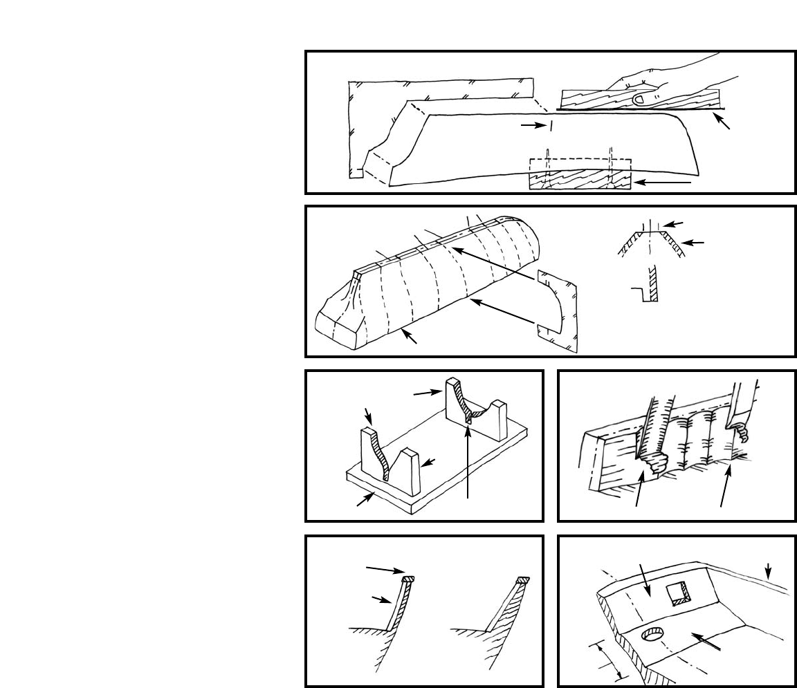
1. Using the Templates
For exact carving to hull lines, a template is
required for the hull profile and each of the
nine stations (Figure A-1). You will find a
template set printed on heavy stock paper in
the kit. Cut the templates out carefully with
a No. 11 hobby knife. Do not use scissors!
You will want a nice smooth edge.
Option-The profile template can be cut at
Station 5 to make fitting easier. Just make
sure you have the keel straight and don’t
build in a knuckle. Likewise, the station
templates can be cut at the bulwark. If you
do this, mark the width of the hull at each
station on top of the bulwark beforehand
and carve to these marks.
FIG. A-1 KIT TEMPLATES
OPTIONAL CUT
(SEE TEXT)
STATION
PROFILE
5
2. Carving the Hull
Cut a wooden block from scrap to about 3”
x 1” x 3/4” thick. Screw the block to the
deck so the model can be held in a bench
vise for carving. First, check the accuracy of
the profile and correct it as necessary, using a
long sanding block (Figure A-2).
Next, mark the centerline, rabbet lines
(where hull meets keel) and station lines on
the model (Figure A-3). Place the station
marks on the center of the hull bottom and
on top of the rails so the marks won’t be
carved off as you work. Also, add the
breadth marks on the rail if you elected the
option noted above.
Start carving approximately at Station 5
(maximum beam) and progress forward,
then aft, using chisels and gouges to cut
away excess wood. Avoid carving against the
grain by shifting forward or aft of Station 5
until you find a spot where you are going
with the grain. Basswood carves easily, so
you probably won’t have much problem with
the grain.
Carve very slowly and take off a little wood
at a time. Fit the templates as you go. Carve
until the template fits reasonably well, then
use sandpaper to obtain the final shape. At
first the templates will not fit very well. You
must compare the template to the hull and
visually decide where to remove wood. Cut a
little off, then re-check the template.
Finally, draw a few horizontal pencil lines
(like waterlines) and the vertical station lines
on the hull. Use these to visually check the
shape of the hull. Hold the hull at various
angles, and look to see if the pencil lines are
fair (even). If you have any unfairness, dips
or bump, they can usually be found with this
visual check. You can also use a stiff stick of
wood, about 1/8” square, and lay it on the
hull at various locations. Dips in the hull
will show up under the stick.
Sand the stern transom with a sanding block.
3. Carving the Bulwarks
Make yourself a temporary cradle to secure
the hull while carving (Figure A-4). This
cradle also will serve to hold the model for
most of the remaining work. Make the cra-
dle so the model sits in it with its waterline
parallel to the baseboard and table. The
tops of the cradle should be below the
waterline. Later, when you are ready to
paint, attach a pencil on top of a wooden
block and slide it along the table to mark
the location of the waterline.
The machine-carved hull has bulwarks thick-
er than scale so they won’t break while inside
the kit box. The upper surface is cut to the
underside of the cap rail. After you carve the
outside of the hull, the bulwarks will be
thinner. If more than 1/16" thick, it will be
necessary to carve the inside of the bulwarks.
This is the most difficult part, so work slow-
ly as you carve (Figure A-5). After carving,
sand the surfaces smooth. If you happen to
have or want to buy a powered rotary tool
like a Dremel, there are many cutters avail-
able to quickly reduce the bulwark thickness.
Note that bulwark stanchions go onto the
inboard side of the bulwarks. T
ogether with
the bulwark (planks on a real ship) they
must fit under the cap rail which is only
5/32" wide. If the stanchions will not fit,
make them a little thinner, or better, sand
the inside of the bulwark a little more at the
top. You can then taper the inside down to
the deck without reducing the thickness at
the deck. You won’t really see that the bot-
tom is thicker than the top. Of course, you
could use a wider cap rail but don’t get it too
wide or the scale will not look proper. Figure
A-6 is a cross section through the bulwark
showing the options.
4. Carving the Inside of the
Transom & Counter
The top of the transom should be about
3/32" thick. If necessary, carve the transom
down on the inside, tapering to the counter
line. Like the bulwarks, a rail sits atop the
transom. The counter is that portion of the
stern from the transom down to the deck.
This should be a slightly curved shape. See
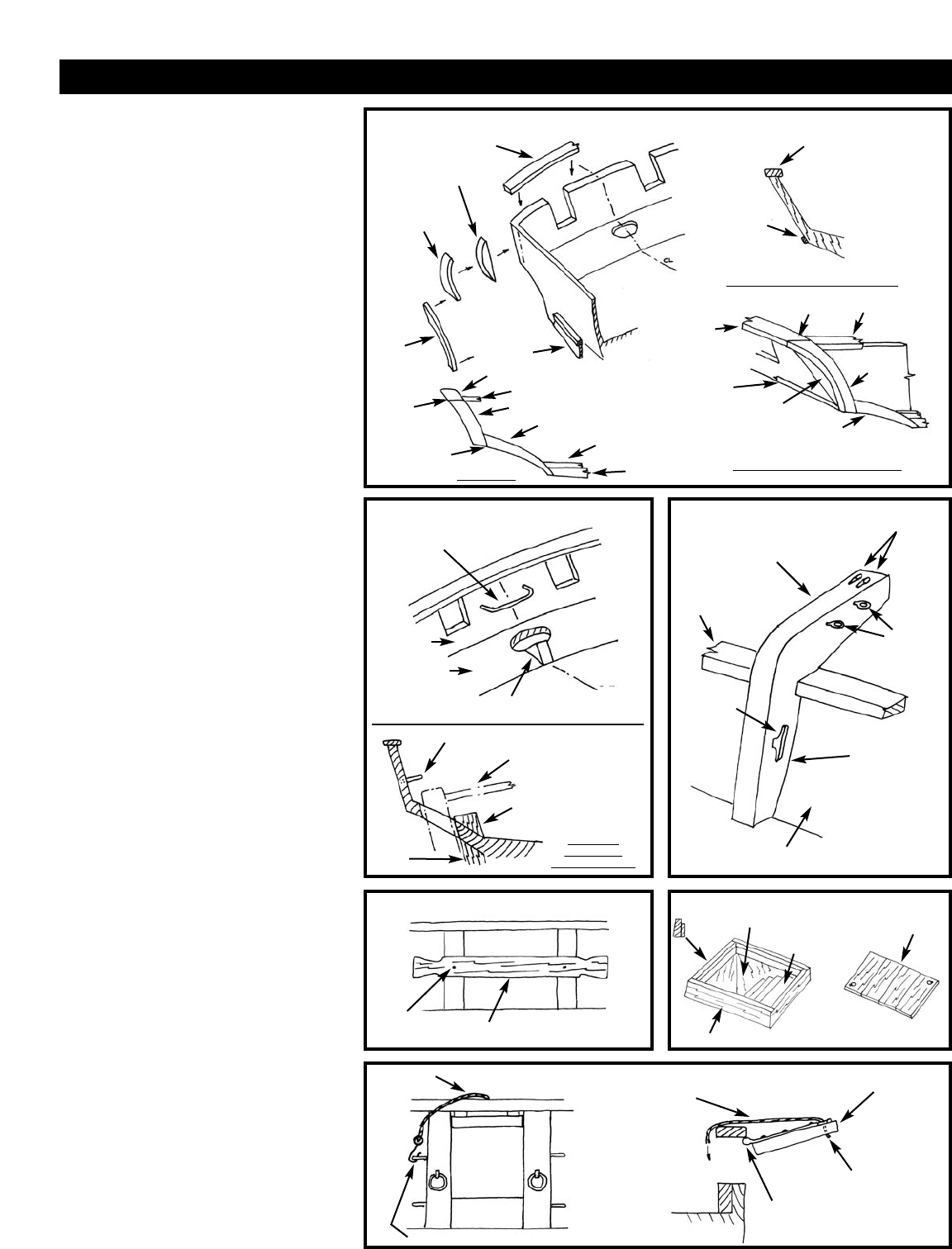
Figure A-7 for a transom and counter view.
The sketch also shows the openings that will
be cut later.
Transom Option - On a machine-carved
hull the wood grain at the stern is in the
wrong direction. If you are worried that the
transom might split, you could add a thin
basswood sheet on the outside to strengthen
it. You could even cut out the transom com-
pletely and add a sheet transom.
At this stage, the basic hull is fully carved.
Sand the entire hull with #220 grit sandpa-
per for the final smoothing. Be careful not to
round the upper edges of the rail or at the
rabbet. These should be sharp corners.
FIG. A-2 CORRECTING THE PROFILE
FIG. A-3
MARKING THE HULL
FIG. A-4 CRADLE
FIG. A-6 BULWARK SECTIONS FIG. A-7 TRANSOM & COUNTER
FIG. A-5 CARVING
BULWARKS
TEMPLATE
MARK STATIONS
MARK RABBET
STA 4
STA7
1/4"
3/8" PLYWOOD
CAP RAIL CL
TRANSOM
SLIGHT
CURVE
BULWARK
COUNTER
DECK
STANCHION
UNIFORM THICKNESS THICKER AT DECK
CUT SLOT
FOR KEEL
MARK
CENTER LINE
FIT TEMPLATES
USE GOUGE FIRST SMOOTH WITH CHISEL
MARK STATIONS ON TOP OF RAIL
CROSS SECTION
RAIL
CL RABBET
WOOD TO
BE CUT AWAY
SANDING BLOCK
BENCH VISE BLOCK
STATION
5
6
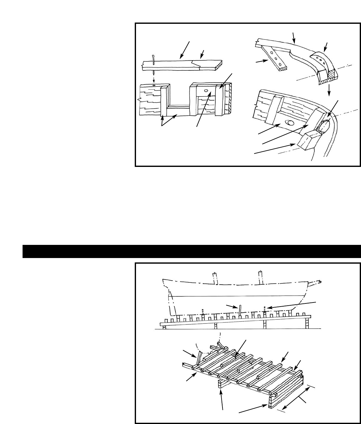
1. Installing the Keel, Stem
& Sternpost
The keel, stem & sternpost are laser-cut
parts. Taper the stem and install the parts
(Figure B-1). Note that the hull plan shows a
scarf joint between the keel and stem with a
step in the middle of the joint. This step has
been eliminated in the laser-cut part. Also,
the stem is shown to be made up of two
pieces. A one piece stem is provided instead.
Use pins or dowels to position the parts
before gluing. Scrape off any glue squeeze-
out. Fill any gaps remaining at the glue
joints with wood filler and then sand.
2. Installing the Rudder
The rudder, a laser-cut part, can be shaped
and installed now or later. The rudder is
tapered and has a round front edge.The pin-
tles & gudgeons are made from brass strip or
by using paper strips. See Figure B-2 for con-
struction.
3. Drilling the Larger Holes
in the Hull
Before going any further with the details,
drill all the large holes in the hull. These
would include a hole for the rudder post &
bowsprit, two mast holes and two pilot holes
in the keel for screws or pins for mounting
the model on a display base. The rudder post
hole will need to be filed to an oval shape as
shown on the plans. For the mast holes,
make a drill guide jig so you will drill at the
correct mast rake angle (see Figure B-3 for
some ideas).
4. Holes to be Drilled as
Work Progresses
There will be other holes to drill as the work
progresses. For example, the hawse holes for
the anchor cable are drilled through the bul-
warks forward. Holes will be required in the
deck for the galley funnel, the capstan, bitts,
and the pumps. You will also need to drill
small holes for inserting eyebolts that hold
blocks for the rigging and gun lines, holes
for belaying pins, and holes for pinning vari-
ous parts in place.
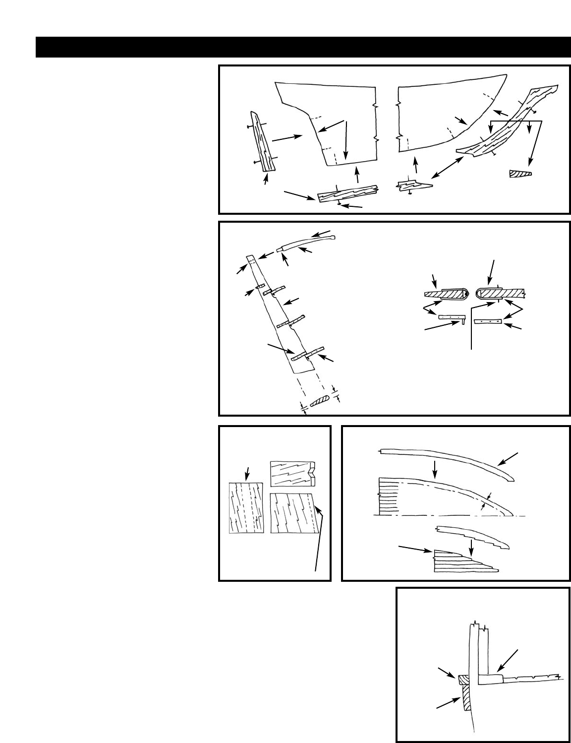
5. Planking the Deck & Installing
the Waterway
The deck planking supplied in the kit is a
scored basswood sheet. To represent caulked
seams darken the scored lines. The Painting
and Staining Section of these instructions
provide some suggestions how to do this. To
fit the sheet, first make a paper pattern of the
deck area. Make sure the scored plank lines
are parallel to the centerline when the sheet
is installed. Glue the sheeting down with
contact cement or airplane-type cement (see
gluing notes in the Painting and Staining
Section). Before you glue the deck consider
the options as follows:
Individual Planks -You could lay individual
planks instead of the scored sheeting, but
wood for this is not included in the kit. If
you elect to do this, paint one edge of each
plank black or brown. When the planks are
glued together, the color will show up as
caulking between planks.
Waterway -Along the inside of the bulwarks,
flush with the deck or just slightly thicker,
there is a waterway-nibbing strake. If you
want to add this detail, cut the edge off the
scored deck, the width of the waterway, and
glue the waterway to the edge of the sheet.
Figure B-4 illustrates the procedure. You
STAGE B: COMPLETING THE BASIC HULL STRUCTURES
FIG. B-1 KEEL, STEM & STERNPOST
PIN OR DOWEL ALL PARTS
GLUE
TAPER THE
STEM
1/8" 1/16"
LASER-CUT
PARTS
GLUE
FIG. B-2 RUDDER
PINTLE & GUDGEON DETAIL
1/16"
ROUND THE EDGES
CUT TENON
LASER-CUT
RUDDER
CUT
HOLE
PINTLE
BRASS
CHAIN
STRAP
GUDGEON
TILLER (LASER-CUT)
1/8"
TAPER & ROUND FRONT
RUDDER
(TOP VIEW)
STERNPOST
(TOP VIEW)
GUDGEON
BRASS
STRIP
PIN IS OPTIONAL
PINTLE
SOLDER
OR
EPOXY PIN
FIG. B-3 JIG
FOR MAST HOLES
FIG. B-4 WATERWAY NIBBING STRAKE
FIG. B-6 WATERWAY STRIP
& WALE
MAST RAKE ANGLE
WOOD
BLOCK
DRILL
GUIDE
ANGLED
HOLE
ANGLED
HOLE
WATERWAY
CUT IF INCLUDING
THE NIBS
WATERWAY
STRIP
WATERWAY
INBOARD
WALE
CUT-OFF TO
ADD WATERWAY
TO EDGE
GLUE ON
TOP OR EDGE
SCORED DECKING
DRILL
GUIDE
WITH "V"
SLOT
7
could also install a waterway without cutting
the nibs. Another way, the scored decking
could go into the bulwark, and a thin water-
way glued on top of the decking.
6. Creating the Ladder Way Hole
The ladder way shown on the plan indicates
an open hatch with a ladder. If you want to
do this you must cut a hole into the deck. If
not, the hatch can have covers. The details
will be discussed in Stage D.
7. Cutting Out the Gunports
& Transom Ports
Cut the gunport openings and transom ports
according to plan. Be careful cutting the
gunports. After cutting, the remaining bul-
wark will be fragile until the cap rail is
installed. Use a fine razor saw blade to cut
the vertical sides and then cut the bottom
with a hobby knife.
8. Installing Bulwark Stanchions
& Cap Rail
With the bulwarks in a fragile state, now is
the time to install the cap rail and bulwark
stanchions. Install the stanchions first, then
the cap rail. While you are at it, up forward,
add the inboard side of the stem, knight-
heads and hawse timbers, and drill the hawse
holes. Also, add the doublers in way of the
sheet and tack sheave holes, and the bow
fairlead for rigging lines atop the rail. Drill
the fairlead holes before installation. Figure
B-5 should clarify the details.
9. Installing the Outboard
Waterway Strip & Wale
The waterway on the deck of the real ship is
a wide plank that protrudes outboard just
past the normal hull planking. For our solid
wood hull you need to add a 1/6" square
strip outside the hull port and starboard for
the full length to simulate the outboard edge
of the waterway.
Below the waterway strips add a 1/32" thick
wale strip. The profile view on the plans
show the wale shape. Note that it is wider
forward and tapers to a more narrow plank
aft. See Figure B-6 for a cross section view in
way of the waterway and wale.
Before proceeding with additional work it is
best to mount the hull. This step will help
prevent details from becoming damaged dur-
ing handling and will allow you to make any
alignments that require a true waterline. Prop-
er mounting of the hull is very important and
will allow the accurate building and aligning
of the remainder of the model. The kit does
not include any parts for mounting. However,
the following suggestions are provided.
1. Mounting Board with Two Pedestals -
A common mounting for ship models is a
wooden baseboard with two wooden or brass
pedestals. For a homemade board, a nice
looking hardwood such as cherry, walnut,
and maple would be ideal. You can round
the top edges of the baseboard, or cut a sim-
ple chamfer. If you own a router, or can
borrow one, you will be able to cut a nice
fancy edge on the baseboard. Stain the base,
if necessary, and give it a few coats of varnish
or finish like Minwax.
The pedestals could be wood or brass. One
pedestal needs to be longer than the other
because you should have the model mounted
with the waterline parallel to the baseboard.
If you decide on this type mounting you
should already have drilled pilot holes for the
screws as noted earlier. For Dapper Tom, the
pedestals should be located near station 4
and 7. If something went awry and the
waterline is not level, you can add a brass
shim under one pedestal to correct it.
2. Launching Ways - A second type of
mounting that can be employed is the
launching ways, which are most suitable for
models without sails. Figure C-1 illustrates a
simple design. Drilling of the keel is still
required to insert rods that anchor the model
to the ways. The launching ways should be
mounted on a baseboard or could be placed
in a diorama comprised of boatyard ground
activity.
Baseboards, pedestals, and launching way
kits are available from Model Expo
(www.modelexpo-online.com).
STAGE C: MOUNTING THE HULL
FIG. B-5 BULWARK DETAILS
FIG. C-1 LAUNCHING WAY MOUNTING
ALIGNMENT
PIN OR NAIL LASER-CUT RAIL
FORWARD
TYPICAL BULWARK
STANCHION
GUNPORT
FRAMING DOUBLER IN
WAY OF SHEET
& TACK SHEAVE
HOLES
AFT SIDE OF
STEM PIECE
KNIGHTHEAD
HAWSE
TIMBER
LASER-CUT RAIL RIGGING
FAIRLEAD
BLOCK
PIN
RAIL
CL
CL
CL
CL
BOWSPRIT
HOLE
STRIPWOOD RAIL AFT
WATERLINE
PARALLEL TO BASE METAL ROD
OR WOOD
DOWEL
IN KEEL
BASE
KEEL BLOCKS
CROSS TIMBERS
SUPPORT
RAIL
SIDE SUPPORT
STRUTS
1/4" SQUARE
WOOD FOR
1/8" - 1/4" SCALE
MODELS
SUPPORTBLOCKS
HEIGHT SET SO MODEL WATERLINE
WILL BE PARALLEL TO BASE
SIDE SUPPORT
STRUTS P/S
ABOUT
1.5 X BEAM
OF HULL
8
STAGE D: ADDING THE HULL DETAILS
1. General Notes
Don’t forget to file off any flash on Britannia
metal fittings, clean the fittings and then prime
them with grey primer before final paint.
Locate deck fittings and place them into
position. This can be done by measuring
from mast holes, station lines and centerline
(tick off from plans). Next, mark their posi-
tions by drilling holes into the deck and
inserting locating pins or dowels which will
be inserted into holes that you will need to
drill into each deck piece. Before permanent
installation, paint them according to the
Dapper Tom color scheme or your choice of
color. Having been pre-fitted, and with the
pins in place, they will be easy to put back
where they belong.
If wooden parts are not painted prior to
installation, at least make sure you have the
part sanded and ready for painting in place.
Use as little glue as necessary on parts. Watch
out for that glue squeeze-out. It’s hard to
remove if left to harden.
2. Transom Rail, Mouldings,
Counter Detail, & Main Boom
Sheet Rod
The transom rail (or taffrail as it is generally
called) curves both fore and aft and across the
top and sides of the transom so it is best cut
out of a wider piece of stripwood. Some steam
bending may be required at the side corners,
or the side rail portion can be cut to shape
from a wider block.
The transom extends beyond the sides of the
hull. This extension is not a part of the
machine-carved hull, so you first must add
the extension before installing the rails.
On the sides, the rail meets a fashion piece
that curves down to the waterway strip and
wale. Along the bottom of the transom out-
board, add a moulding strip. Figure D-1
should clear up this often confusing area.
Inboard on the counter, there is a a small
block to be added on centerline just forward
of the rudder post opening. This is actually
the top of the sternpost on a real ship. On the
transom, fit the main boom sheet traveler rod
made from wire. See Figure D-2 for a sketch
of the area.
3. Catheads, Bulwark Sheaves,
Cavils, & Gunport Lids
When you installed the bulwark stanchions
earlier, most of the bow timbers and hawse
holes were finished at that time. There are
still a few more details for the bulwarks
unless you got these done while installing the
bulwark stanchions.
The catheads are laser cut parts. Before
installing, drill the holes for the anchor tackle
and add the eyebolts for the jibboom guys
(Figure D-3).
FIG. D-1 TRANSOM RAIL & FASHION PIECE
FIG. D-2 INBOARD STERN DETAILFIG. D-2 INBOARD STERN DETAIL FIG. D-3 CATHEADS
FIG. D-4 CAVILS FIG. D-6 LADDER WAY
TAFFRAIL
TAFFRAIL
SIDE
TAFFRAIL
MOULDING
STRIP
FASHION
PIECE
TRANSOM
EXTENSION
PIECE
JOINT CAP
RAIL
SIDE
TAFFRAIL
WALE
WALE
JOINT
TRANSOM
COUNTER
DECK
DRILL
HOLES
FOR
ANCHOR
TACKLE
EYEBOLTS
FOR
JIBBOOM
GUYS
LASER-CUT
CATHEAD
CLEATFOR
BELAYING
ANCHOR
TACKLE
THIS SIDE OF
CATHEAD MAY
BE SHAPED TO
FIT FLUSH
AGAINST
BULWARK
CAP RAIL
BULWARK
HOOK TO EYEBOLT ON SIDE OF STANCHION
CL
BOOM SHEET
TRAVELER ROD
JOINT
FASHION
PIECE TAFFRAIL
CAP RAIL
SIDE TAFFRAIL
FASHION PIECE
WATERWAY STRIP
WATERWAY
STRIP
SECTION THROUGH TRANSOM
OUTBOARD VIEW AT CORNER
SIDE VIEW
TRANSOM
EXTENSION
PIECE MOULDING
STRIP ALONG
BOTTOM OF
TRANSOM
TAFFRAIL
BLOCK REPRESENTING
TOP OF STERN POST
TRAVELER ROD
RUDDER & TILLER
BLOCK
STERN
POST
SECTION
THROUGH
RUDDER HOLE
HOLE IN CARVED HULL
LADDER - MAKE FROM
STRIPWOOD
OPTIONAL
HATCH COVER
SCRIBE
OR GLUE
INDIVIDUAL
BOARDS
1 OR 2
PIECES
PIN OR
JUST GLUE 1/32" THICK CAVIL
DECK
CAP RAIL
COAMINGS - CUT FROM STRIPWOOD
LIFT LINE
LIFT LINE
LID
CASTING
DRILL HOLE,
GLUE LINE
GLUE OR PIN CASTING
TO CAP RAIL
FIG. D-5 GUNPORT LIDS
9
Install the cavils, cut from stripwood, across
the bulwark stanchions in locations shown on
the plans (Figure D-4).
The gunport lids are Britannia castings. Install
these in the open position. Add the line for
retrieving and holding up the line. The cast-
ing has a ring where the line attaches but it is
molded in flat with the casting so is useless for
attaching a line. Drill a small hole at this ring,
insert and glue the line (Figure D-5).
4. Deck Bitts, Fife Rails, Pin Rails,
Capstan, Galley Funnel, Hatches,
Ladder Way, Pumps, & Skylight
The main hatch, galley hatch, capstan, galley
funnel, bowsprit bitts, riding bitts and fife
rails are all Britannia castings. Drill the neces-
sary holes and install the fittings. The riding
bitts have a stripwood bar between the port
and starboard bitt. Glue this in place.
Fife Rails - Each of the fife rails consists of
the topsail sheet bitts casting and two
rail/stanchion pieces. The sheet bitt casting
slopes aft, so drill the holes in the deck
accordingly. Drill holes for belaying pins in
the rails and glue the rails to the Bitts. The rail
stanchions also require holes in the deck.
Galley Hatch & Galley Funnel - The base
of the galley funnel and the galley hatch cast-
ings are slightly larger than shown on the deck
plan. They will still fit, just adjust by moving
the funnel aft a bit.
Ladder Way - As noted earlier, the ladder way
hatch can be open showing the ladder or
closed with hatch covers. The hatch coam-
ings, ladder, and/or covers are to be made
from stripwood (Figure D-6).
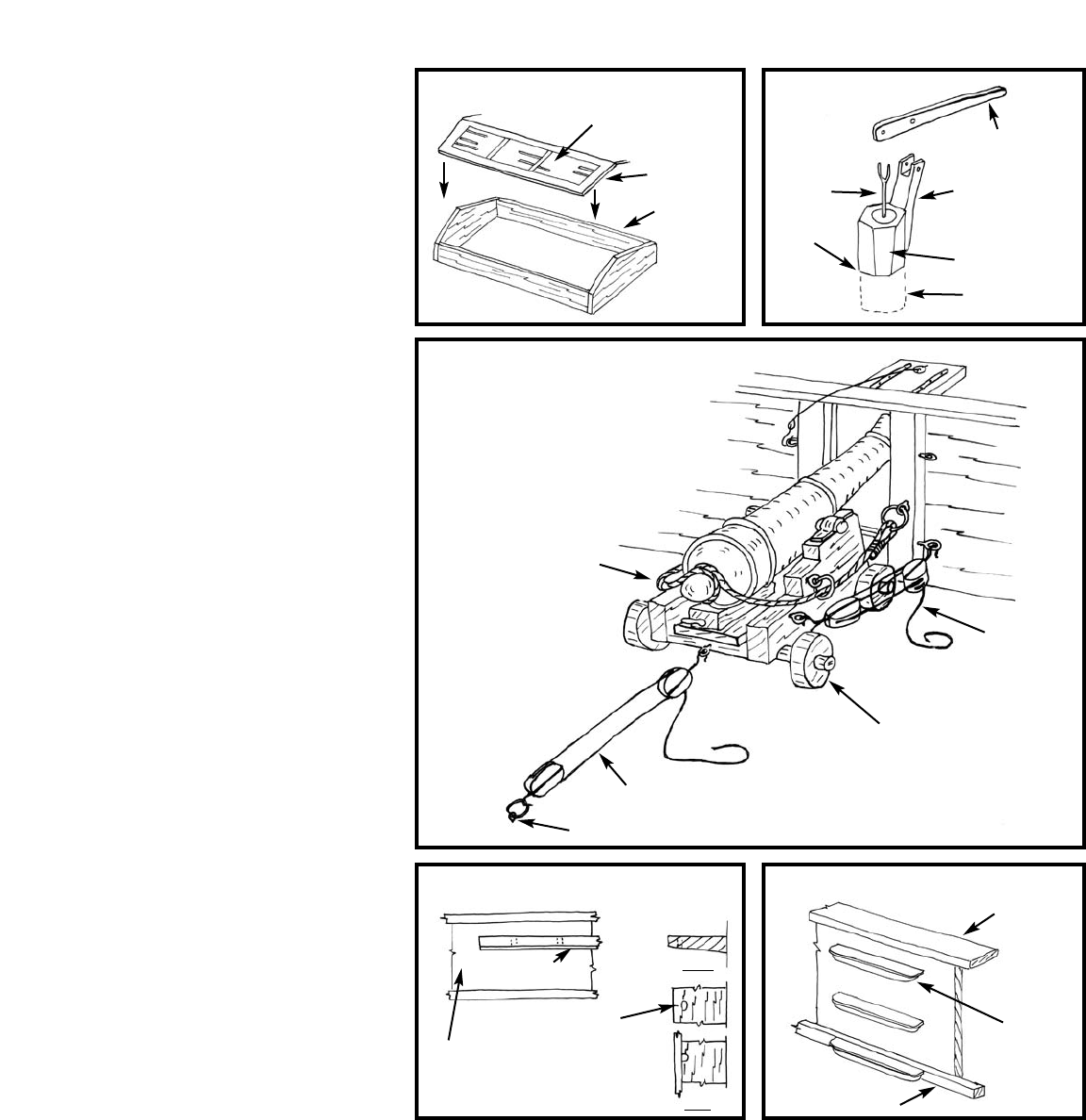
Skylight - Figure D-7 illustrates the con-
struction of the wooden skylight. The top is
rather small for much detail so the glass can
be simulated by painted light blue with black
ink bars.
Pin Rails - There is a pin rail between the
bulwark cap rails forward and pin rails at vari-
ous locations along the bulwarks. Make the
rails from stripwood, and drill the holes and
install the belaying pins before gluing the rails
in place.
Pumps - Two wooden tub pumps are
required on the deck just aft of the main
mast fife rails. No casting is provided so these
must be made from wood. Figure D-8 shows
a suggested method.
5. Cannons
Now the fun begins. You will find the work a
little tedious, but take your time and you will
have some nice deck detail. The carriages and
cannon barrels are Britannia castings. Glue
the barrels atop the carriages. Drill a hole on
each side of the carriage and insert a small
eyebolt. The eyebolts are for hooking the gun
outhaul tackles. Below the eyebolts drill
another hole and add an eyebolt and split
ring. This fitting is a fairlead for the breech
line, but at our model scale, this fitting could
be omitted. Your choice.
After the guns are fitted and painted, add an
eyebolt and split ring to form a ring bolt in
the bulwark stanchions on each side of the
gunports. This is for securing the breech line.
Figure D-9 illustrates the cannon rigged in
position. In back of each gun on the deck,
there is an eyebolt and split ring as shown on
the plan. This fitting is for a tackle to inhaul
or train the cannons during battle. The actual
tackle is portable, so it could be omitted on
the model.
6. Channels & Side Ladder
There are three channel pieces port and star-
board that support the lower deadeyes. Make
these from stripwood and shape the inboard
edge to the hull curvature. Drill holes large
enough for the deadeye strops to pass
through. Or, notch the hole and add a strip
over the edge after the deadeyes are installed
(Figure D-10).
The side ladder is three wooden steps on the
outside of the bulwark. Make it from strip-
wood (Figure D-11).
FIG. D-7 SKYLIGHT FIG. D-8 PUMPS
FIG. D-9 CANNON RIG
FIG. D-10 CHANNELS FIG. D-11 SIDE LADDER
PAINT TO FAKE
GLASS & BARS
BREECH
LINE
CASTING
INHAUL TACKLE
EYEBOLT IN DECK
CAP RAIL CAP RAIL
2 PIECES
OR CARVE
FROM ONE
STRIP
WATERWAY STRIP
CHANNEL
WATERWAY STRIP
BULLWARK
HOLE FOR
CHAIN PLATE
OPTION - CUT SLOT,
ADD SEPARATE STRIP
AFTER DEADEYES
ARE INSTALLED
SIDE
TOP
OUTHAUL
TACKLE
BOTH SIDES
1/32"
BASSWOOD
HANDLE
SIDE BRACKET
WIRE
HOLE
IN DECK
FILE FLATS OR
LEAV E ROUND
WOOD DOWEL
1/16"
BASSWOOD
D
S
S
S
Most references call a mast a mast, and
anything else such as a boom, yard, gaff,
and bowsprit a spar. Let’s stick with
that definition.
There are two mast assemblies for the Dapper
Tom. They are a foremast & main mast. The
foremast is built up in three sections: lower
mast, topmast, & topgallant mast. The main
mast is built up in only two sections: lower
mast & topmast. Each of the sections are con-
nected at the doublings (upper and lower
mast overlap) by mast caps and trestletrees
which in this kit are Britannia metal castings.
Lower mast trestletrees are supported from
the mast by bibbs (or cheeks) cut from wood
sheet. The castings for the trestletrees include
crosstrees and tops where appropriate, all in
one casting which eliminates a lot of assembly.
The mast and spar dowels included in the kit
are round. True to scale, masts and spars must
be tapered for their full length.
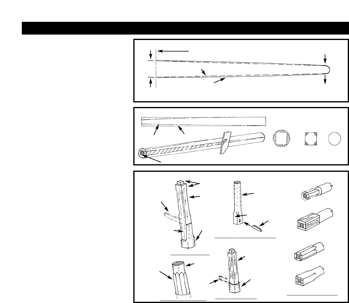
1. Shaping the Masts
Establishing the Correct Curve
of the Masts
The correct shape of the masts are shown on
the plans. Each of the mast sections should
be tapered in a slight (parabolic) curve (Fig-
ure E-1). However, for this kit scale, it may
be difficult to accomplish a parabolic shape.
A straight line taper should be sufficient.
The best way to taper the masts from dowels
is to cut the taper into squares, then
octagons, and finish by sanding into a round
shape (Figure E-2).
Shaping the Mastheads & Heels
The next areas of the masts to be shaped are
the mastheads and heels where the masts join
together at the doublings (see plans for loca-
tion). Each mast has a head and a heel
located at its uppermost and bottom ends,
respectively. The masthead on the lower
masts and fore topmast is from the trestle-
trees upward to the cap.
T
o accommodate the mast caps and trestletree
fittings, the mastheads must be shaped square.
The lower masts also have flat sides below the
trestletrees where the trestletree cheeks (also
called bibbs) are to be glued.
The heel of the topmasts and topgallant mast
is round where it passes through the mast cap
at the top of the doubling and square at the
bottom at the trestletrees. The transition
from the square to the round portion is
shown on the plans. A fid (protruding bolt of
wood or iron) is located in each topmast and
topgallant mast heel to prevent them from
falling through the holes formed by the
trestletrees. The lower masts at the deck are
octagonal in shape. As an option the masts
could be left round.
Figure E-3 illustrates the shaping of the
mastheads, heels and the fid. Since you are
dealing with wood dowels, the sketch also
shows how to build the square or octagonal
ends by adding wood to the cut-end. Adding
wood is necessary because the dimension
across the flats of the square must be the
same as the dowel diameter. Consequently,
the diagonal of the square is greater than the
dowel diameter.
2. Assembling the Masts
First, install the lower mast top fitting, then
the topmast heel into the fitting. Make sure
you already have the fid installed into the
topmast heel. Then slide the mast cap over
the top mast and secure the cap onto the
lower masthead. Make sure the topmast lines
up straight with the lower mast when look-
ing fore and aft and that the two mast
sections are parallel when looking from the
side. You can now glue the fittings. Assemble
the fore topgallant mast to the topmast in
the same manner.
Mast Details - Before painting and staining
the masts there are a few details to add. The
fore topgallant mast and the main topmast
should have a shoulder where the lifts and
stays are seized near the top of the mast. If
you have not tapered the masts with the
shoulder, do so now, or cut a groove at that
point. This is needed so the rigging lines do
not slide down.
The topgallant and topsail tyes pass through
sheaves in the masts. You don’t need a sheave
on the model, but drill a hole through the
masts for the lines.
The head of the fore topmast has a cheek
block port and starboard with two sheaves.
Make the block with stripwood and drill a
hole where the sheaves would be. The holes
on the starboard side are for passing the jib
10
STAGE E: MAST & SPAR CONSTRUCTION
FIG. E-1 TAPER ON MASTS & SPARS
FIG. E-2 SHAPING THE MASTS
FIG. E-3 SHAPING MASTHEADS & HEELS
CENTER OF A YARD, OR MAXIMUM DIAMETER
OF A MAST, GAFF, OR BOOM
THIS IS THE DESIRED CURVE. MATHEMATICALLY, IT IS A PARABOLA.
IT’S CLOSE TO THE ARC OF A CIRCLE. SIMPLY TAPER THE SPAR
GRADUALLY FROM MAXIMUM DIAMETER TO THE END.
FOR YARDS, MAKE SURE BOTH SIDES ARE THE SAME.
STRAIGHT LINE
DRAW SQUARE ON END
MINIMUM
DIAMETER
MAXIMUM
DIAMETER
MAST
DOWELTAPER
REQUIRED
SQUARE
SQUARE
1. CUT SQUARE
2. ADD WOOD
OCTAGON
SQUARE
FINAL SHAPES
TOPMAST & TOP GALLANT HEEL
FORE TOP MASTHEAD
LOWER MASTS AT DECK
SPAR DIAMETER BUILD-UP
LOWER MASTHEADS
FID
ROUND
ROUND
SQUARE
TRESTLE TREE
CHAMFER
EDGES
TOP
TRESTLE
TREES
ROUND
BELOW
TRESTLE
TREES
ROUND
BELOW
TRESTLE
TREES
8-SIDED
(OCTAGON)
FLAT SIDES IN
WAY OF THE
CHEEKS &
UNDER THE
TRESTLE
TREES
1ST CUT
SQUARE
2ND CUT
8-SIDED
SANDED
ROUND
11
stay and the jibsail halliard. The port side
block is not used or is for other lines not
rigged on this model. Figure E-4 illustrates
the mast details.
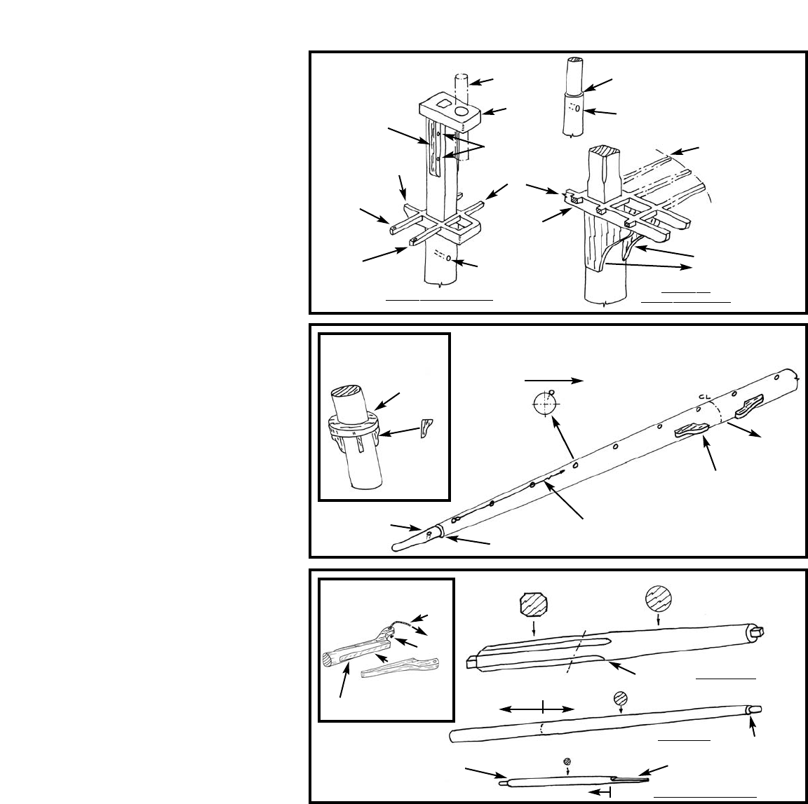
Main Boom Rest - The main mast has a rest
for the boom. The rest is a laser cut part but
requires support chocks cut from stripwood
(Figure E-5).
3. Shaping & Detailing the Spars
Yards
Shape the yards in the same manner as the
masts. The maximum diameter of each yard is
at its center. Taper the yards outward from
each center.
Yard Details - Cut a shoulder on each end of
the yards which is a stop for lifts and
footropes. Also, drill holes (sheaves on real
ship) in the ends of the yards for the sheets
from the sail above. Though the plans do not
show them, most likely the yards have chocks
in way of the parrels and trusses.
Jackstays (12A) consists of a series of eyebolts
thru which a line is passed and fixed at the
ends of the yard. The line and eyebolts are
used for attaching the head of the sail and the
footrope stirrups. Note that the eyebolts are
on top of the yard but slightly forward of the
yards centerline. You have a lot of holes to
drill for the eyebolts. While you are detailing
the yards you might as well add the jackstay
lines after the eyebolts are installed.
Figure E-6 illustrates a typical yard.
Boom & Gaffs
The main boom and fore and aft gaffs also
taper, but the maximum diameter of each spar
should be about one-third from its fore end.
Like the yards, cut a shoulder at the outer end
of these spars. The boom and gaffs require
that jaws be added to their throats for joining
to the masts. The jaws are laser-cut wood
parts in this kit (Figure E-7).
Bowsprit, Jibboom, & Dolphin Striker
The bowsprit is tapered forward from the
hull. At the outer end, cut the square shape to
fit the bowsprit cap (Britannia casting found
in kit). The aft end of the bowsprit tapers
from the bow back to the bitts. From the end
of the stem back to the bitts on deck, the
shape is octagonal with a square end to fit the
bowsprit bitts hole. If using the dowel, you
will need to add wood as you did with the
squares on the masts. Or, you could forget
this task and just leave the bowsprit round.
The jibboom should be straight from the aft
end to the bowsprit cap, then tapered forward
of the cap. At the outer end cut a shoulder for
rigging stops.
Where is the aft end of the jibboom? The
plans show only that it stops at the bow, but
this is not the complete story. Typically, Balti-
more Clipper jibbooms ended somewhere
along the outer end of the bowsprit lashed
down to a saddle on the bowsprit. So for
Dapper Tom, it is recommended that you stop
the jibboom just aft of the forestay.
The dolphin striker is a simple tapered round
spar. Cut a flat at the upper end where it will
be glued to the bowsprit cap. At the bottom
of the spar, a wooden or metal cleat is fitted to
each side, which guide the fore topgallant stay
and martingale stay.
Figure E- 8 illustrates the bowsprit, jibboom,
and dolphin striker details.
Assembly -Glue the bowsprit cap onto the
bowsprit. Make a saddle for the jibboom,
then insert the jibboom. Make sure the jib-
boom lines up with the bowsprit and then
glue it to the saddle atop the bowsprit. Glue
the dolphin striker (proper name martingale)
to the bowsprit cap. Add the bees for the fore
topmast stays, chock stops for rigging collars,
lashings, eyebolts, and other details as shown
in Figure E-9.
4. Installing the Mast & Bowsprit
Assemblies
Before installing the masts, shape and slide on
the mast coats which are laser cut rings (Fig-
ure E-10). The mast coats on a real ship are
actually canvas covers over the wedges holding
the masts in place.
Place the masts and bowsprit in the holes you
FIG. E-4 MAST DETAILS
FIG. E-6 TYPICAL YARD
FIG. E-8 BOWSPRIT,
JIBBOOM &
DOLPHIN STRIKER
CHEEKS P/S
MAKE FROM
WOOD SHEET
SHOULDER AT UPPER PART
OF MAIN TOPMAST & FORE
TOPGALLANT MAST
FORE TOP
MAIN TOP SIMILAR
HOLE FOR YARD TYE
CROSS TREES
TOPGALLANT
MAST
CHEEK
BLOCK P/S
DRILL HOLE
FOR SHROUDS
TRESTLE TREES
CROSS TREES
CASTING
CASTINGS
SHEAVE HOLES
TRESTLE TREE
HOLE FOR
TOPSAIL YARD TYE
FORE TOPMAST HEAD
HOLE FOR SAIL
ABOVE SHEET
SHOULDER
JACKSTAY
EYEBOLTS
FORWARD
FORWARD
FIG. E-5
MAIN BOOM REST
FIG. E-7 BOOM &
GAFF JAWS
LASER-CUT
RING
JACKSTAY LINE
FED THROUGH EYEBOLTS–
FIX AT ENDS
CHOCKS IN WAY OF
PARRELS & TRUSSES
CHOCKS
FROM
STRIPWOOD
PARREL
FLATTEN
SIDES
LASER-CUT
JAW HALF
AT CAP
TAPER
FLAT AT CAP
AT
BITTS AT BOW
AT CAP
SHOULDER
SHOULDER
AT END OF STEM BOWSPRIT
JIBBOOM
DOLPHIN STRIKER
STRAIGHT TAPER
KNOT
12
drilled into the hull. It is suggested that you
do not glue the masts and bowsprit into the
holes. The rigging will hold them in position.
Furthermore, if the model gets restored in the
future, the masts and bowsprits can be easily
removed.
Check the alignment of the masts and
bowsprit. If not straight, looking aft, or at the
correct angle shown on the plans, you can
shim the holes. If necessary, drill the holes
larger to accommodate shimming.
1.Rigging Identification
Most all of the rigging is identified on the rig-
ging plan by number. The small belaying pin
plan on the rigging plan shows a recommend-
ed location for belaying the numbered lines.
The key to the plan numbers is as follows:
Note: Numbers 1 through 24 are standing
rigging. Use the black rigging line supplied in
the kit. Numbers 25 through 50 are running
rigging. Use the tan rigging line supplied. If a
standing rig has a tackle on the end, use tan
line for the tackle. P/S indicates lines that are
both port and starboard.
1. Shrouds (for all masts, P/S)
2. Ratlines (for all shrouds, P/S)
3. Deadeyes (for all shrouds, P/S)
4. Lanyards (for all deadeyes, P/S)
5. Fore Topgallant Mast Stay
6. Jib Stay (includes an ouhaul tackle at the
bowsprit cap)
7. Traveler Ring at Jib Stay
8. Fore T
opmast Stay (P/S)
9. Forestay
10. Footropes (for all yards, P/S)
11. Stirrups (for all yards, P/S)
12. Fore & Main Topmast
Futtock Shrouds (P/S)
12A. Jackstays (for all yards, P/S))
13. Fore & Main Topmast Backstays (P/S)
14. Fore Topgallant Mast Backstays (P/S)
15. Lifts (for all yards, P/S)
16. Main Stay (P/S)
17. Spring Stay
18. Main Topmast Stay
19. Bobstay
20. Bowsprit Shrouds (P/S)
21. Martingale Stays
22. Martingale Backropes (P/S)
23. Manropes
24. Fore & Main Lower Yard Slings
25. Fore & Main Sail Tacks (P/S)
26. Fore & Main Sail Sheets (P/S)
27. Fore & Main Sail Clew Garnets (P/S)
28. Fore & Main Topsail Sheets (P/S)
29. Fore & Main Topsail Clew Lines (P/S)
30. Fore Topgallant Sail Sheets (P/S)
31. Fore Topgallant Sail Clew Lines (P/S)
32. Fore Lower Yard Braces (P/S)
33. Fore Topsail Yard Braces (P/S)
34. Fore Topgallant Yard Braces (P/S)
35. Main Lower Yard Braces (P/S)
36. Main Topsail Yard Braces (P/S)
37. Fore & Main Topsail Yard Tye
38. Fore & Main Topsail Yard Halliard
Runner & Fall
39. Fore Topgallant Yard Tye
40. Fore Topgallant Yard Halliard & Fall
41. Fore & Main Gaff Peak Halliards
42. Fore & Main Gaff Throat Halliards
43. Fore & Main Gaff Vangs (P/S)
44. Main Boom Topping Lifts (P/S)
45. Main Boom Sheet
46. Main Gaff Ensign Halliards
47. Jib Halliards
48. Jib Inhaul
49. Jib Sheet (P/S)
50. Anchor T
ackle & Fall P/S)
A few rigs are not numbered but are shown
on the rigging plan to some degree. They are
as follows and will be detailed later in these
instructions:
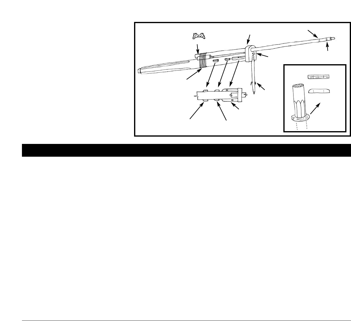
Parrel (or parral) - On upper yards which
can be raised or lowered, these lines hold the
yard against the mast. Beads, or rollers, on the
lines allow the yards to move freely along the
mast. There is a detail shown on the upper
right side of the plan.
Truss - On lower yards, there are no parrels,
instead, a fixed line holds the yards against the
mast. It has two running ends, each of which
has a tackle secured to eyebolts in the deck at
the mast and the tackle belays to the fife rail.
Thus, the truss can be tightened or loosened
at deck level. The truss is rope on the Dapper
Tom. On later ships the rope truss was
replaced by an iron fitting.
Jibboom Guys - These guys are shown in a
plan view on the left hand side of the rigging
plan. Note that the inboard ends have a tackle
at the cat heads.
If you are not familiar with the names and
functions of rigging lines, the book How to
Build First-Rate Ship Models From Kits by
Ben Lankford contains a description of Nauti-
cal terms (See Bibliography).
Note: Throughout these instructions the low-
est yards and their sails are referred to as
“Lower Yards or Sails”. A more proper term is
“Course Yards or Sails”.
2. Line, Block, & Deadeye Sizes
There is a limited number of different size rig-
ging lines in the kit. The following is a
suggested list of line size use:
Standing Rigging (Black Line)
0.008" Dia. Line - All Ratlines, Fore & Main
Topmast Shroud Lanyards, Fore Topgallant
Shrouds, Topgallant Yard Lifts, & Fore Top-
gallant Stay.
0.012" Dia. Line - All Yard Footropes &
Stirrups, Main Lower Yard & Topsail Yard
Lifts, Fore & Main Topmast Shrouds & Fut-
tock Shrouds, Fore Topgallant Backstays,
Jibboom Guys, Fore & Main Lower Shroud
Lanyards, Martingale Stay & Backropes,
Bowsprit Shrouds, Fore Topmast Stays, Main
Topmast Stay, & Jib Stay.
0.021" Dia. Line - Fore & Main Lower
Shrouds, Fore & Main Topmast Backstays,
Spring Stay, & Lower Fore Yard Lifts
0.028" Dia. Line - Forestay, Main Stays,
Bobstay, & Fore & Main Lower Yard Slings
& T
russes.
FIG. E-9 BOWSPRIT ASSEMBLY
FIG. E-10 MASTCOAT
STAGE F: GENERAL RIGGING INFORMATION
SADDLE BLOCK
LASHING LASER-CUT RING
MASTCOAST
ROUND
TOP EDGES
CAP CASTING
CLEATS
BEES FOR
FORE TOPMAST STAYS
CHOCK STOPS FOR
BOBSTAY & BOWSPRIT
SHROUD COLLARS
CHOCK STOPS
FOR FORESTAY
COLLAR
HOLE FOR JIB STAY
HOLE FOR FORE
TOPGALLANT STAY
EYEBOLT FOR
JIB IN HOLE
13
Running Rigging (Tan Line)
0.008" Dia. Line - Topgallant Sail Clew lines
& Sheets, Fore & Main Topsail Clew Lines,
Topgallant Yard Braces, Fore & Main Gaff
Vangs, & Main Gaff Ensign Halliards.
0.012" Dia. Line - Fore & Main Topsail Yard
Braces & Sheets, All Jackstays, Fore & Main
Sail Clue Garnets, Jib Stay Outhaul Tackle,
Jibboom Guys Tackle, Boom Topping Lifts,
Jib Halliard & Sheets & Downhaul, Jib Stay
Inhaul & Outhaul tackle, & Topgallant Yard
Tye & Halliards.
0.018" Dia. Line - Fore & Main Sail Tacks
& Sheets, Main Boom Sheet, Fore & Main
Topsail Yard Tyes & Halliards, Fore & Main
Yard Truss Tackle, Gaff Peak & Throat Hal-
liards, Lower Fore & Main Yard Braces, &
Anchor Tackle.
0.040" Dia. Line - Anchor Cable.
Blocks - Like the lines, the blocks for running
rigging are not sized on the plan. However,
blocks are sized to suit the line that runs
through their sheaves. The following list sug-
gests the block sizes that should be used with
the line sizes provided:
0.008" Line - Use 3/32" blocks.
0.012" Line - Use 1/8" blocks.
0.018" Line - Use 5/32" blocks.
Long Tackle Blocks - The plans show several
blocks which are long blocks with two sheaves
in line rather than side by side. None are
included in the kit. However, you can glue
two single blocks together end to end to
simulate the block, or simply substitute a
common double block.
Deadeyes - Use the smaller 3/32" Deadeyes
for the Fore & Main Topmast Shrouds, Fore
Topgallant Backstay, & Bowsprit Shrouds.
Use the 5/32" Deadeyes for Fore & Main
Lower Shrouds, Fore Topmast Backstays,
Main Topmast Backstay, & the Bobstay.
3. Rigging Sail Lines
The Dapper T
om model is intended to be
completed with sails removed. However, even
without sails, some of the rigging lines such as
sheets, tacks, halliards, and clew lines are to
remain, along with their lead blocks. Some of
the lines are to be hooked together, such as
the jib halliard and sheets, and yard clew lines
and sheets. The running ends of these lines
should be belayed at their proper locations.
Installing the sail rigging lines on the Dapper
T
om adds tremendously to the look of the
model, especially at the jib stay where the
contrasting black stay and light running lines,
along with their blocks, create interesting
visual detail.
4. Applying Beeswax to the Lines
Before placing the lines on the model, run the
line through a block of beeswax several times.
Then, run the line through your fingers. This
heats the wax slightly and rubs it into the line.
The beeswax will cut down on fuzz and pro-
tect the line from moisture.
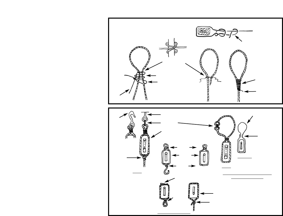
5. Seizing the Lines
Seizing of lines (binding or securing two lines
or different parts of the same line) can be
done as shown in Figure F-1. To prevent seiz-
ings from unraveling, add a touch of CA glue.
For seizings, use the 0.008" line in the kit or
sewing thread.
6. Blocks, Strops, & Fittings
Around the time the Dapper Tom was built,
the use of rope for stropping blocks, and for
parrels and slings on yards, was more com-
mon than iron fittings. However, such items
as iron-stropped blocks, hooks, and eyebolts
were available. There is no sure way to deter-
mine exactly what was on the Dapper Tom.
The details shown in the sketches and plans
illustrate only one of the ways it may have
been done. A block shown lashed into an eye-
bolt could just as likely have been lashed
around the spar without the use of an eyebolt.
A strop is an iron or rope band or grommet
around the shell of a block for attaching lines.
The blocks in the kit are fairly small, so it will
not be easy for you to create the exact detail-
ing. Some modeling shortcuts are in order.
See Figure F-2 for some life-size ship details
and model options.
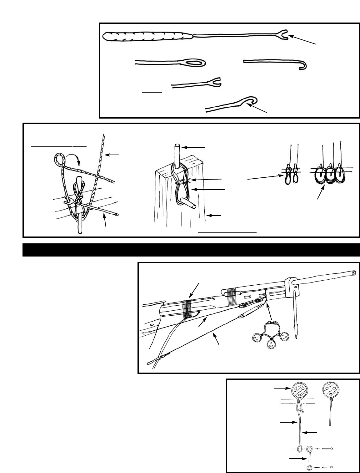
7. Rigging Tools & Belaying Lines
Figure F-3 illustrates some homemade tools
that are essential aids in the rigging process.
Figure F-4 shows some suggestions for belay-
ing lines to belaying pins and cleats.
A word of advice - Rigging plans are hard to
follow. Lines cross each other and they some-
times go behind something or seem to
disappear into thin air. Before you start the
rigging, get a notebook and do a small sketch
of each rigging line on a separate page. Sketch
in where the lines end, such as at an eyebolt
and label these points. If something seems to
be missing when you view your sketches, seek
help or find the answer in a rigging text (con-
sult the bibliography). Use the final sketches
as you rig the model. You won’t need to crawl
your way through the rigging plan again.
When rigging such items as yards, booms
and gaffs, do as much rigging as possible with
the item in hand before installing the part on
the model. Seize the lines to the part and
FIG. F-1 SEIZINGS
FIG. F-2
BLOCKS,
STROPS,
& FITTINGS
CLOVE HITCH
WRAP
THREAD
HOOK
BECKET
EYEBOLT
LASHING
ROPE STROP
TWIST
WIRE
GLUE
GLUE
LINE OR WIRE
SEIZE &
GLUE
NO HOOK
USING RIGGING LINE
SLIPKNOT & GLUE
CLOVE
HITCH
WITH
THREAD
LOOP
THROUGH
LINE
PULL TIGHT,
GLUE, THEN
CUT-OFF ENDS
SLIP KNOT
TOUCH WITH
CA GLUE
CUT-OFF
END
TUCK UP & GLUE
FAKED ON SMALL BLOCK OR SPAR
MODEL OPTIONS
SHIP
SHIP
MODEL
FOR WRAPPING AROUND
YARDS & MASTS
14
FIG. F-3 RIGGING TOOLS
FIG. F-4 BELAYING LINES
CUT WITH SNIPS
PUSH
WOOD HANDLE BRASS ROD
PULL TIGHT
& GLUE
REMOVABLE PIN
THREAD
JIG
ADD WHITE
GLUE TO STIFFEN
FOR AMORE OPEN,
REALISTIC LOOK,
OMIT THREAD &
GLUE COILS TO EACH
OTHER
USE TOOL TO PUSH LINE UNDER PIN
PULL
FLATTEN END,
FILE SHAPE
LARGE
SEWING
NEEDLE
LARGE
SEWING
NEEDLE
BELAYING LINE TO PIN
SEPARATE ROPE COILS
1. Bowsprit Rigging
Begin the standing rigging with the bowsprit.
Add the gammoning (0.012" or 0.021" black
line), which ties the bowsprit to the stem.
Wrap the gammoning neatly, laying each part
of the line side by side as it is wrapped. Next,
install the bobstay (19), then the bowsprit
shrouds (20). Figure G-1 illustrates the rig to
this point. Rigging at the bowsprit will be
completed while and after installing the head
stays. But first, the mast shrouds will be
installed since the head stays and all fore and
aft stays go over the top of the shrouds at the
mastheads.
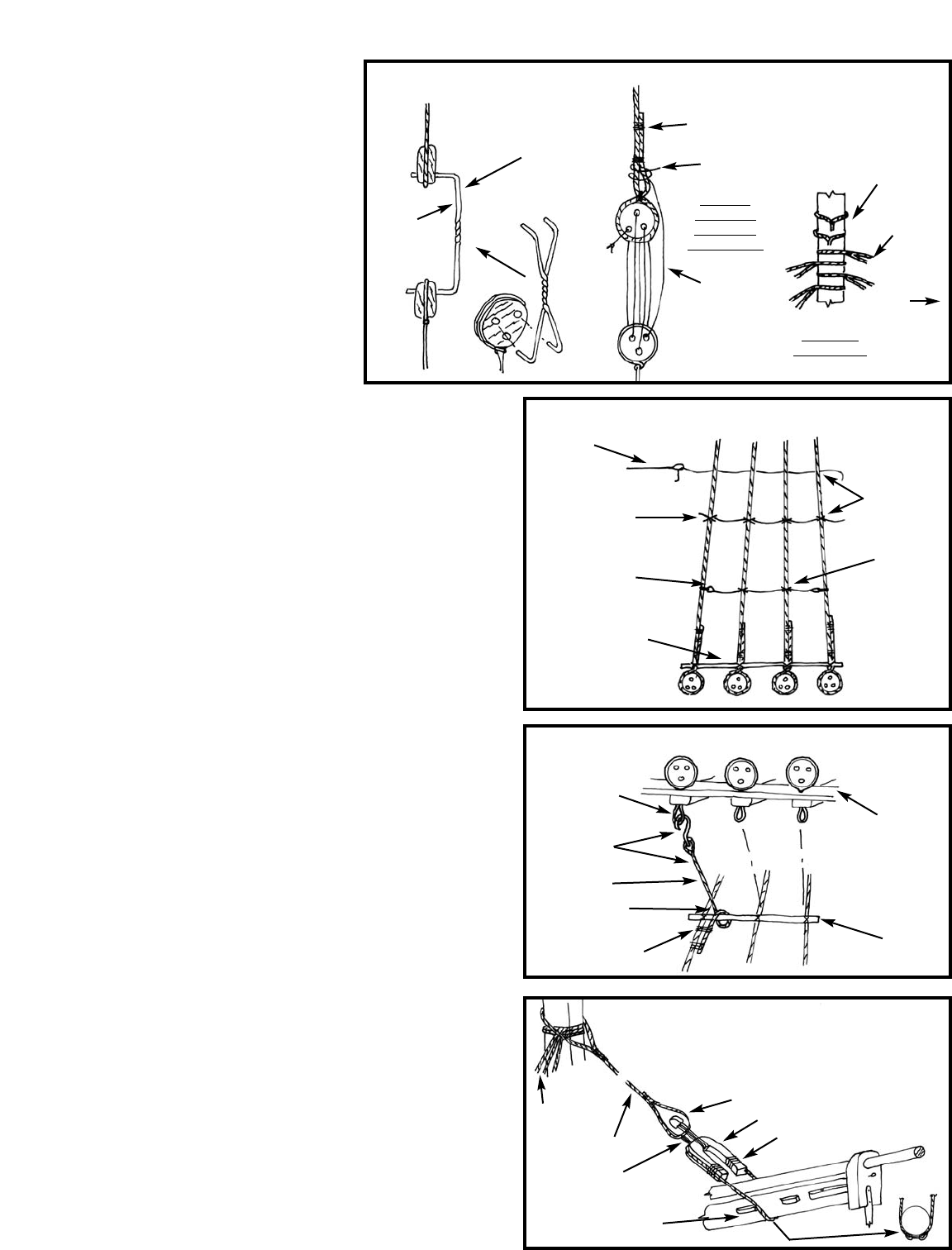
2. Shrouds & Backstays
The lower shrouds (1), topmast backstays
(13), and topgallant backstays (14) are set up
with deadeyes and lanyards at the channels
and attached along the outside of the ship
using chain plates. The lower deadeye strops
and chain plates are to be made of steel wire
provided in the kit (Figure G-2). T
o set up the
shrouds, make a temporary jig of wire to
space the deadeyes as you do the seizings (Fig-
ure G-3). The sketch also shows the sequence
for reeving the lanyards and the proper
sequence for the shrouds going around the
mastheads. Keep an eye on the masts as you
rig the shrouds, so you will not pull them out
of line. After the shrouds are in place, proceed
to add the ratlines and the sheer
poles (Figure G-4). The sketch
shows ship practice and various
model options.
The topmast shrouds are set up
similar to the lower shrouds but
instead of having chain plates they
set up to futtock shrouds (12). The
rigging plan seems to indicate that
the futtock shrouds go to the mast,
but this is not the practice for the
period. They actually seize to the
lower shrouds (Figure G-5).
On this particular ship the topgal-
have enough running rigging
line so it can reach to its final
destination, such as a belaying
pin, with a little line left. Bet-
ter to be too long than too
short. Standing rigging such as
yard footropes are included, as
these would be very difficult
to do with the yard hanging at
the mast.
STAGE G: STANDING RIGGING
FIG. G-1 BOBSTAY & BOWSPRIT SHROUDS
GAMMONING
SHROUDS
P/S
BOBSTAY
COLLAR FOR BOBSTAY
& SHROUDS
FIG. G-2
DEADEYE
STROPS
& CHAIN
PLATES
STROP
TWIST
MODEL
OPTION
CHAINPLATE
NAIL
BACKING
LINK
WIRE
15
lant shrouds have no deadeyes or ratlines. The
shrouds pass through the crosstrees and seize
to the topmast shrouds.
3. Foremast (Head) Stays
Forestay -The forestay (9) sets up to a closed
and open heart and collar at the bowsprit.
The closed heart shown on the plan appears
rather large for this ship. Normally, the open
heart is simpler, and does not straddle the
bowsprit as shown. That would make the
heart much too wide. The hearts in the kit are
laser-cut and reflect the modification. File a
groove around both of the hearts to receive
the stay and collar (Figure G-6).
Figure G-7 illustrates the remaining head
stays; fore topmast stay, jib stay & fore
topgallant stay.
Fore Topmast Stay -The fore topmast stay
(8) is a double line passing port and star-
board through the bees on the side of the
bowsprit and are seized with lanyards to eye-
bolts at the bow. Notice that the hole in the
port bee is a little aft of the starboard bee
hole. Actually, the starboard stay should be
called a spring stay.
Jib Stay - The jib stay (6) is an interesting
stay as it can be moved in or out along the
jibboom with the aid of an outhaul tackle (6
) and an inhaul (48 ) which are attached to a
traveler ring. The ring is not included in the
kit. Fashion it from brass or steel wire. Make
sure you place the ring over the jibboom and
rig this stay before you rig the outermost fore
topgallant stay. The top of the jib stay passes
through a cheek sheave on the side of the
masthead and down to a tackle just above
the deck.
Fore Topgallant Stay - This stay (5) passes
through a hole (and sheave) at the end of the
jibboom, under the starboard cleat on the
dolphin striker, through a lead block on the
starboard side of the bowsprit, then through a
hole in the bow and belays to a pin on the
forward pin rail. This stay could also be set up
to an eyebolt in the bow with lanyards and
not through a hole in the bulwark.
Note: The detail on the rigging plan is con-
fusing. The fore topgallant stay and the
martingale stay appear to cross after passing
the dolphin striker. This is not likely so just
switch the lines with the topgallant going star-
board and martingale going port.
4. Completing the
Bowsprit Rigging
Now that the head stays are completed, you
can finish up the other bowsprit and jib-
boom rigging. Figure G-8 illustrates the
lines discussed.
Martingale Stay & Backropes - This is the
lowest stay on the jibboom. Seize the forward
end around the jibboom outer shoulder. The
stay (21) is lashed to the bottom of the dol-
phin striker. From that point there is a
backrope (22) port and
starboard seized to eye-
bolts at the hull. There is
another martingale stay,
the inner martingale (also
21), attached to the bot-
tom of the traveler ring
and feeds back via the
dolphin striker, through a
lead block on the port
side of the bowsprit to
belay inboard.
Note: Refer back to the
note under fore topgal-
lant stay regarding some
confusion with the
plan detail.
Manropes (23) - Install
an eyebolt port and star-
board on top of the
fairlead block at the bow.
Run the lines to the eye-
bolt stanchions atop the
bowsprit cap. Midway
there are support lines
hanging from the
forestay. A small netting
is shown on the plan
between the port and
starboard manropes. No
netting is provided in the
kit so you can omit it, or
use some netting material
from your local florist.
Jibboom Guys - Use
black line for the guys
and tan for the tackles
set to eyebolts on the
catheads. The outer guys
are secured to the end of
the jibboom and the
inner guys to the jib
traveler ring.
5. Mainmast Stays
Mainstay - This stay (16)
FIG. G-3 SETTING UP THE SHROUDS
FIG. G-4 OPTIONS FOR TYING RATLINES
MAKE A LITTLE LONGER
THAN REQUIRED. LET
LANYARDS PULL
SHROUDS TIGHT.
TEMPORARY
WIRE
JIG
SEIZE
KNOT
STAYS
SHROUDS
TIE LANYARD
& GLUE
LANYARD
SEQUENCE
CUT-OFF
AND GLUE
CLOVE
HITCH
VIEW IS
INBOARD
LOOKING
OUTBOARD
SHROUD
SEQUENCE
PORT
THREAD
WITH
NEEDLE
CLOVE HITCHES
ALL SHROUDS
WOOD SHEER
POLE LASHED
TO SHROUDS
EYE SPLICE
LASHED TO
SHROUD
(REAL SHIP)
FIG. G-5 TOPMAST FUTTOCK SHROUDS
FIG. G-6 FORESTAY
FORE TOP
MAIN TOP
SHROUD
WOOD
STAVE
COLLAR
AT MAST TOP
CLOSED HEART
OPEN HEART
SEIZE
LOWER
SHROUDS
FORESTAY
LANYARD
STOP CHOCK
ON BOWSPRIT
P/S
STROP
HOOK &
LINE
FUTTOCK
SHROUD
LOWER SHROUDS
LASH TO
LOWER SHROUDS

16
is a pair, passing on each
side of the foremast and
setting up port and star-
board with lanyards to the
eyebolts shown on the
deck plan just forward of
the foremast fife rail. The
stay eye would be fitted
with a metal thimble (Fig-
ure G-9). This
arrangement is a common
solution. However, on
some ships the stay could
have set up to bullseyes or
deadeyes at the deck.
There is usually many
solutions to rigging these
old ships.
Spring Stay & Main
Topmast Stay - The
spring stay (17) sets to
eyebolts on the fore and
main mast caps. The
main topmast stay (18) is
seized around the main
topmast and to an eye-
bolt on the foremast cap
next to the spring stay.
Main Topgallant Stay -
This stay is shown but
not numbered or identi-
fied on the rigging plan.
Above the main topmast
stay and shrouds, the top-
mast continues for
another 13 feet or so.
This extension could be
classified as a topgallant.
Therefore, the fore and
aft stay at the top will be
identified as main topgal-
lant stay. Secure the
forward end at the fore
topmast crosstrees.
6. Yard Lifts,
Footropes, Stirrups,
Slings, & Trusses
These lines are a part of
the standing rigging list but we will defer the
instruction to running rigging, Stage H.
These lines are best installed along with some
running
rigging while working with the yards. Just
don’t forget that these lines
are black.
Examine the model before moving to the next
stage. Is a mast or the bowsprit and jibboom
out of alignment? Now is the time to correct
these mistakes.
FIG. G-7 FORE TOPMAST, JIB,
& FORE TOPGALLANT STAYS
FIG. G-8 REMAINING RIGGING AT BOWSPRIT
FIG. G-9 MAIN STAY
AT TOP
JIB STAY
JIB INHAUL
TO PIN RAIL
OUTHAUL
TACKLE
TRAVELER
RING
FORE TOPGALLANT STAY
CHEEK
BLOCK
TACKLE AT DECK
BETWEEN
FIFE RAIL - BELAY
TO FIFE RAIL
FORE TOPMAST STAY
(SPRING STAY)
PORT
FORE TOPMAST
STAY STARBOARD
BELAYTO
PIN RAIL
EYEBOLT &
LANYARD OPTION - SET TO EYEBOLT
WITH LANYARD
LEAD BLOCK
PORT SIDE
JIBBOOM BUYS
P/S
NET
P
S
MARTINGALE
STAYS
MARTINGALE
BACK STAYS
MARTINGALE
BACK STAYS
EYESPLICE
WITH THIMBLE
LANYARDS
EYEBOLTS
IN DECK
EYEBOLT
& LANYARDS
TO PIN
RAIL
MANROPE P/S
MANROPE
SUPPORT
LINE P/S
CATHEAD
JIB
TRAVELER
RING
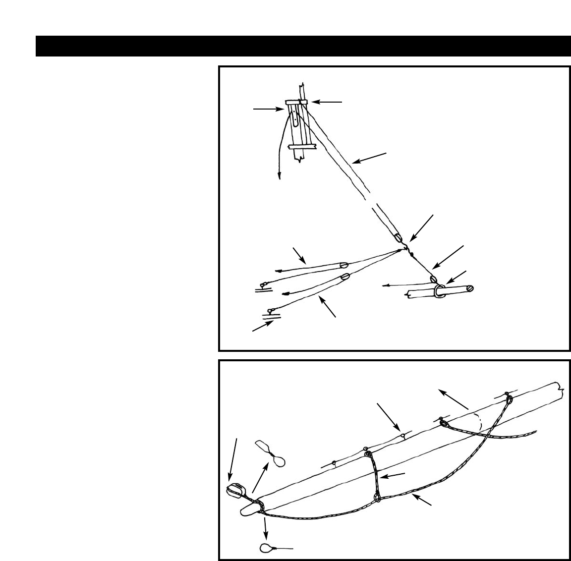
17
Before starting on the running rigging, have all
your blocks stropped and/or seized to a line as
much as possible. Some running lines may
pass through a sheave hole, they require a
block. If so try starting at the block and rig-
ging backward. Of course, if in such a
situation a block is required on both sides of
the sheave, you are stuck with having to seize
at least one of the blocks on the model.
1. Jib Rigging
The only head sail lines shown on the plan are
for a jib. There should have been more head
sails such as a fore staysail and a jib topsail. If
you desire to add any additional sail lines to
your model, consult the Baltimore Clipper
book in the Bibliography. It would be advis-
able and add to the model if you at least add
halliards and downhaul at the fore topgallant
stay. Rig it like the jib halliards.
The jib halliard (47) is seized to the topmast
cap, goes down through a single block, back
up through a cheek sheave on side of the mast-
head, and down to its belaying pin on deck.
With no sail, the lower block is brought down
and placed just above the bowsprit and
hooked to the jib sheets (49). But wait, the
lines are floating in thin air. That’s because a
line is missing from the plan. There should be
a downhaul for the jib sail. To correct this
omission, add a single block lashed to the trav-
eler ring. The downhaul will be hooked along
with the sheets to the lower halliard block. The
downhaul then goes thru the block on the
traveler ring and belays on the pin rail at the
bow. The jib sheets could be omitted, but if
fitted the standing end is secured to an eyebolt
on the port and starboard cap rail, and the line
belayed to the pin rail on the bulwarks. Figure
H-1 illustrates the entire set-up.
2. Lower Yards
Jackstays - The jackstays were already installed
when you detailed the yards in Stage E so no
further work is required.
Footropes (10) & Stirrups (11) - Remember
these are black standing rigging lines. Beeswax
the footropes heavily so you can droop them
into a natural hanging curve and they will stay
in place. Note the stirrups and inboard end of
the footrope goes on the aft side of the yard
(Figure H-2).
Braces - For now, just add the brace blocks
at the ends of the yard (also Figure H-2).
The main yard blocks face forward and fore
yard blocks face aft. The brace rigging will be
discussed later.
Clew Garnets (27), Sheets (26), & Tacks
(25) - These are all sail lines hooked together
when the sails are removed. The clew garnets
are the only lines actually attached to the yard.
You could hook up the sheets and tacks after
the yard is installed on the model, or add them
now. Both the sheets and tacks go to the hull
thru sheaves in the bulwark and belay to cavils
on the bulwark stanchions with one exception.
The forward tacks go to the end of long poles
called boomkins protruding from the hull
(Figure H-3).
Topsail Sheet Blocks - Refer to the topsail
sheet discussion in the next paragraph.
Slings - The lower yards have no halliard and
tye, but a fixed sling (24), since the yards are
not hoisted like other yards. The sling can be
attached to the yard now, but cannot be fully
completed until the yard is in place since the
sling goes around the masthead (Figure H-4).
Truss - The truss (not numbered) holds the
yard against the mast. The line is pulled up
tight by the port and starboard ends which are
attached to a tackle at the deck (also Figure
H-4). On some ships the truss is flipped and
the tightening tackle placed at the top above
the yard instead of at the deck.
Lifts - The lifts (15) for this particular ship
reconstruction appear to be fixed standing rig-
ging at the caps. However, on most ships of the
period a more common arrangement would be
to have the lifts pass through blocks at the cap
and down to a tackle on deck. See Figure H-5
for both the fixed lifts and running option.
STAGE H: RUNNING RIGGING
FIG. H-1 JIB HALLIARD, DOWNHAUL, & SHEETS
FIG. H-2 YARD FOOTROPES & STIRRUPS, BRACE BLOCKS
CHEEK
BLOCK
JIBBOOM
BELAY
TO FORWARD
PIN RAIL
JIB SHEETS
EYEBOLT
IN CAP RAIL
BRACE
BLOCK
FORWARD
JACKSTAY
STIRRUP
FOOTROPE
CL
BELAY TO PIN RAIL
ON STARBOARD BULWARK
BELAY TO PIN RAIL
ON BULWARK
HOOK TOGETHER
JIB DOWNHAUL
JIBSTAY TRAVELER RING
JIB HALLIARD
SET FIXED END TO EYEBOLT
OR WRAP AROUND THE CAP
P
S

18
3. Topsail Yards
The jackstays, footropes & stirrups, lifts and
brace blocks are essentially the same as for the
lower yards.
Clew Lines and Sheets - The clew lines (29)
are just like the lower yard clew garnets, just a
different name. There are no tacks. The sheets
(28) hook to the clewline block, then go
through a sheave (a hole will do) at the ends of
the lower yards, through the block on the
lower yard inboard of the clew garnet block
and down to the belaying pins (Figure H-6).
Parrels - The topsail yards move up and
down. To hold the yard against the mast a par-
rel is used. The parrel is a beaded fixture so the
yards will move freely along the mast. Howev-
er, because of the small scale of this model, a
simple line without the beads will be adequate
(Figure H-7).
Tye and Halliards - The halliard ( for lifting
the topsail yards) is made up of a tye (37)
attached to the yard, a runner (38), and finally
a fall (also 38) which is the tackle at the deck.
The tye passes through a sheave in the mast.
Just drill a hole if you have not already done so
while making the masts.
For both fore and main rigs, the runner seizes
to an eyebolt in the channels. The lower fall
block also seizes to an eyebolt in the channels
but on the opposite side of the ship. One dif-
ference between fore & main, the rig is flipped
so the foremast fall is on the starboard side and
main mast on the port side. Figure H-8 illus-
trates the rig.
4. Fore Topgallant Yard
Everything is basically the same as the topsail
yards except for the halliard. The runner is
eliminated so you have only the tye (39) and
fall (40). The lower fall block is hooked at the
fore top, or at the channel but the line still
goes to the deck for belaying.
5. Rigging the Yard Braces
You should have the blocks on the yards
already. Now you need lead blocks at the
masts. Figure H-9 shows where these blocks
are located. All brace lines belay at deck level.
Note that the sketch shows the main topsail
yard lifts set to eyebolts on the fore lower mast
cap. An option would be to fix the blocks and
fixed ends to a rope collar around the mast
head just under the cap.
6. Fore & Main Gaffs
& Main Boom
The foresail on the fore gaff of the lower fore-
mast is loose footed. The gaff is fitted with
vangs (port & starboard) that extend from the
peak of the gaff to the outboard deck to steady
the gaff when the sail is furled. Peak and throat
halliards raise and lower the gaff. For our
model, without sails, the sheet for the foresail
would have been removed with the sail. The
remaining peak and throat halliards and the
vangs are identical to the mainsail.
Unlike the foresail, the mainsail has a boom
and a boom topping lift (44). Normally, when
the sail is furled or removed, the gaff is lowered
to lay on top of the boom. However, for the
model the gaff looks better in the up position
and the vangs help fill in the open space. The
rigging plan shows it this way.
Gaff Throat and Peak Halliards - Rig the
throat (42) and peak (4) halliard lower blocks
and peak halliard seizing on the gaff before
installing the gaff. The upper blocks are
secured below the top and mast cap respective-
ly. The hauling end of the peak halliard should
go down on the starboard side of the boom
and the throat halliard on the port side. The
belaying plan is confusing because it indicates
what appears to be eyebolts in the deck
between the main mast fife rails. In this case,
there would be a tackle in the halliards hooked
to these eyebolts and the fall lines belayed to
the fife rail. The fore fife rail has no indication
at all where the halliards are belayed. To sim-
plify the rigging, it is suggested that no tackles
be installed and the halliards simply be belayed
to pins in the fife rail. See Figure H-10 for the
halliard arrangement.
Boom Topping Lifts, Gaff Vangs, & Boom
Sheet - Figure H-11 illustrates these running
lines. The topping lifts (44) are a pair of lines
port and starboard. Quite a hefty rig but the
mainsail would be quite heavy when the sail
is furled.
FIG. H-3 LOWER YARD CLEW GARNETS, SHEETS & TACKS
FIG. H-4 LOWER YARD SLING & STRUSS
CLEW GARNET P/S
HOOK TOGETHER
TACK P/S
SHEET P/S
BELAYTO
CAVIL
EYEBOLT
HOLE (SHEAVE)
TACK P/S
BOOMKIN
BULWARK
(AT FORE YARD)
BULWARK
(AT MAIN YARD)
BULWARK
(AT MAIN YARD)
SLING
TRUSS
CLEATS ON
FORWARD SIDE OF YARD
EYEBOLT AT
DECK P/S
BELAYTO
PIN RAIL
AT BOW
CL
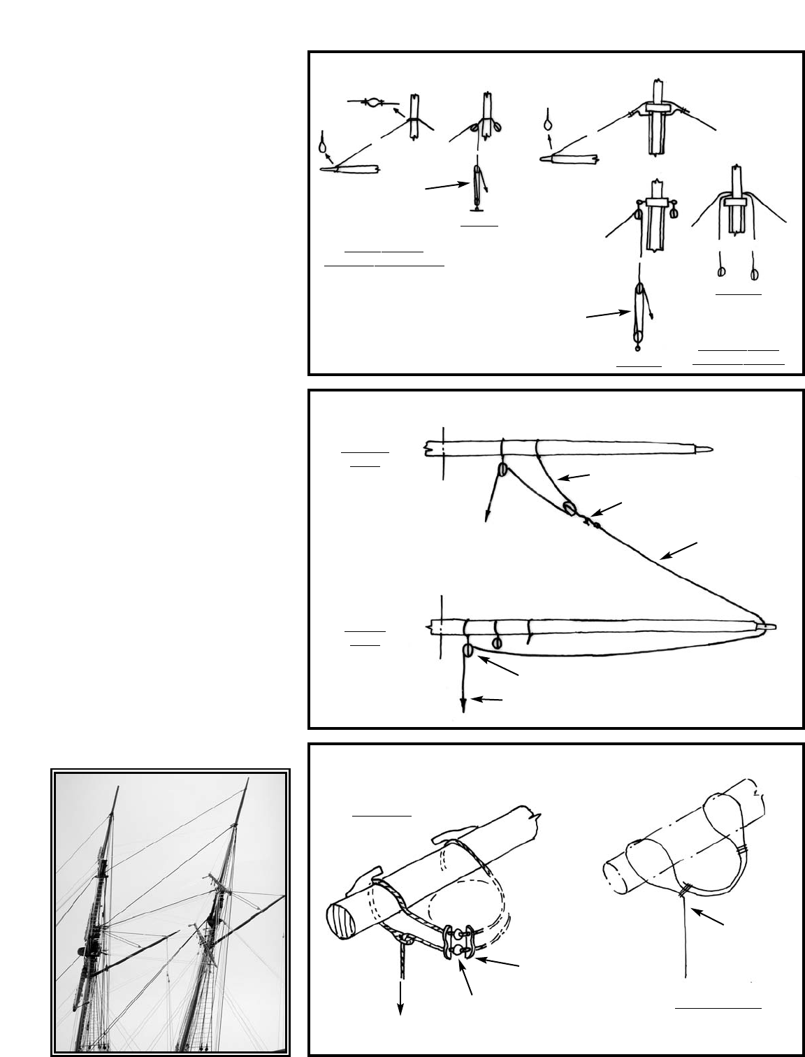
19
The vangs (43) are fitted port and starboard.
The plan does not clearly show where the
fixed end of the fall is located. Seize it to an
eyebolt in the deck close to the bulwark or on
top of the cap rail directly in line with the line
on the plan.
The main boom sheet (45) lower block is fit-
ted with a ring around the traveler rod on the
transom. The running end can be belayed port
or starboard to the cavils on the bulwark stan-
chions. The lead block on the deck can be
considered optional.
7. Anchor Tackle
Figure H-12 shows the anchors, port and star-
board, rigging and stowage. Coil the anchor
cables on the deck.
8. Final Touches
After all the rigging is in place, re-check every
line, and make sure all the seizings are sound.
If necessary, add another touch of CA glue to
seizings. Check to see if there are any shiny
places on the rigging. If necessary, tough-up
standing rigging with black paint, or black liq-
uid shoe polish. For running rigging, use a tan
stain, or brown liquid shoe polish.
Check to see if any of the painted wooden
parts were marred or scratched during the rig-
ging process and touch-up as necessary.
Congratulations—you’ve done it! We look for-
ward to helping you with your next ship
modeling project.
FIG. H-5 YARD LIFTS
FIG. H-6 TOPSAIL YARD CLEWLINES & SHEETS
FIG. H-7
YARD PARRELS
TACKLE
AT DECK
FIXED
FIXED
RUNNING
RUNNING
OPTION 1
OPTION
LOWER YARDS
& FORE TOPSAIL
TOPSAIL
YARD
LOWER
YARD
REAL SHIP
MODEL OPTION
MAIN TOPSAIL
& FORE TOPGALLANT
OPTION 1
NO BLOCKS AT CAP
TACKLE
AT DECK
BELAY AT
BULWARK
PIN RAIL
SHEET LEAD BLOCK
BELAYAT FIFE RAIL
YARD
COULD ALSO
ELIMINATE
THE HAULING
END
MAST
BELAY TO
DECK B ITTS
BEADS (10 PER YARD)
RIBS (6 PER YARD)
CLEWLINE
HOOK TOGETHER
SHEET
Below and on the following pages
are photos of the Dapper Tom
rigging on our prototype model.
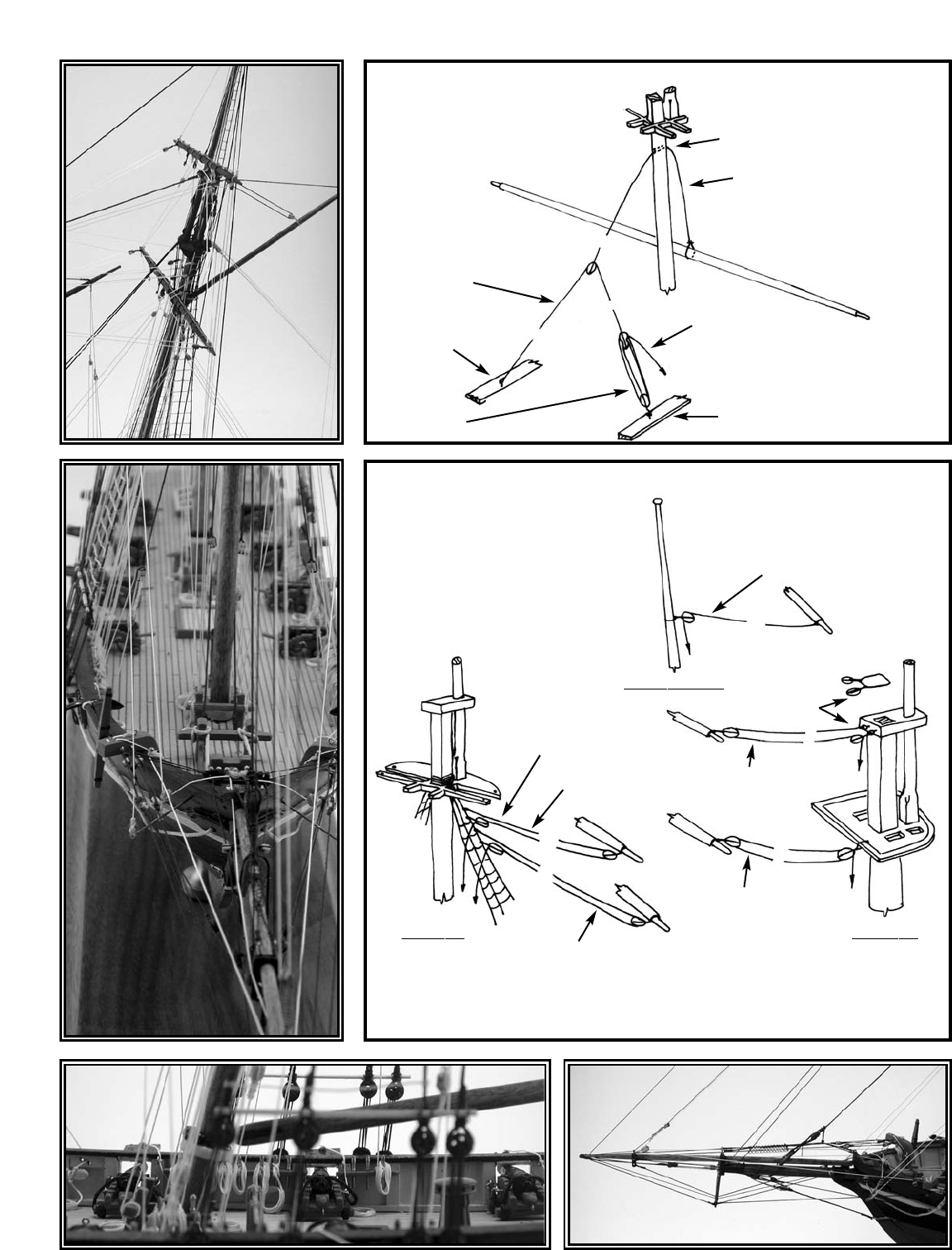
20
FIG. H-8 TOPSAIL, YARD TYE & HALLIARD
FIG. H-9 YARD BRACES
HOLE IN MAST
TYE
RUNNER
EYEBOLT IN
CHANNEL
TACKLE PORT
AT MAINMAST
& STARBOARD
ATFOREMAST
CHANNEL
FORE TOPGALLANT
YARD BRACE
LASH LINES &
BLOCKS TO
LOWER SHROUDS
FORE TOPSAIL
YARD BRACE
OPTION-COLLAR
AROUND MAST
MAIN TOPSAIL
YARD BRACE
MAIN LOWER
YARD BRACE
FORE LOWER
YARD BRACE
ALL BRACES PORTS & STARBOARD
MAIN TOPMAST
MAIN TOP FORE TOP
BELAYTO
PIN RAIL
HALLLIARD

21
FIG. H-10 GAFF THROAT & PEAK HALLIARDS
FIG. H-11 GAFF VANGS, BOOM TOPIPNG LIFTS & SHEET
FIG. H-12 ANCHOR TACKLE
PEAK HALLIARD
COLLAR
AROUND
TRESTLE
TREE
TO STARBOARD SIDE
OF MAST TO PIN
IN FIFE RAIL
TO PORT SIDE
OF MAST TO PIN
IN FIFE RAIL
BELAY TO PINS
ON BULWARK
PIN RAILS
COLLAR
AROUND
MAST
D
D
S
STHROAT
HALLIARD
VANGS
P/S
RING
CAVIL
TOPPING LIFT
P/S
BELAYTO
BULWARK
PIN RAIL
EYEBOLT IN DECK
OR IN RAIL
LASH TO
BULWARK
CLEAT
INBOARD
BELAY TO PIN
RAIL OR A
CLEAT ON
THE CATHEAD
LEAD BLOCK
P/S
(OPTIONAL)
TRAVELER ROD
ON TRANSOM
BOOM SHEET
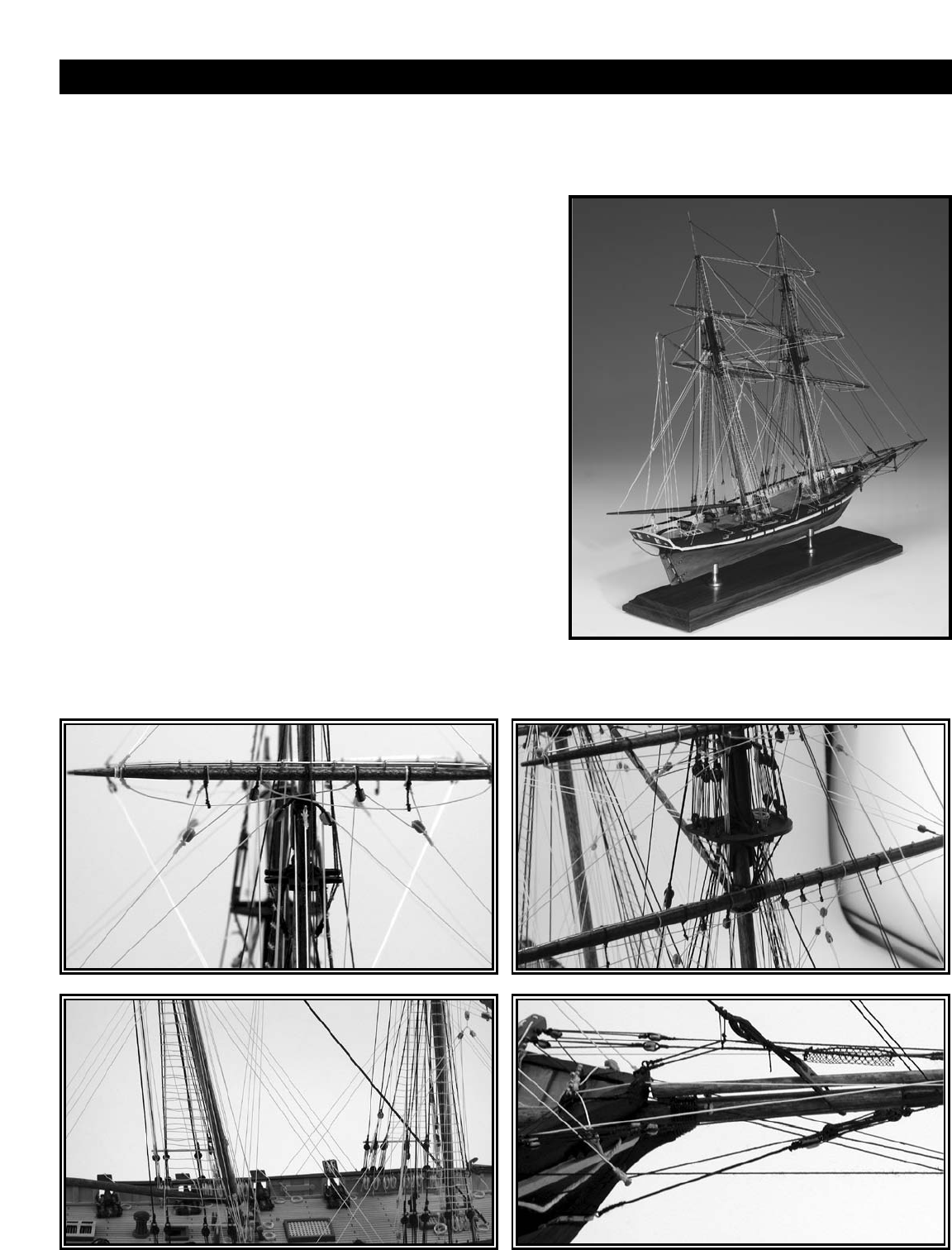
1. The Baltimore Clipper
by Howard I. Chapelle. Marine Research Society 1930. Reprinted by Bonanza Books, Crown Publishing.
This is a complete history of the Baltimore Clipper type. It contains many plans of contemporary schooners.
2. The Young Sea Officer’s Sheet Anchor
by Darcy Lever. 1819 (reprinted)
Block and spar details, and typical rigging techniques of the period.
3. Steel’s Elements of Mastmaking, Sailmaking and Rigging
by David Steel. 1794 (reprinted)
Details of masts and spars, block, rigging practices, and rigging sizes.
5. The Art of Rigging
by George Biddlecombe. 1848 (reprinted)
There is essentially an update of David Steel’s earlier work.
6. The Neophyte Shipmodeller’s Jackstay
by George F. Campbell. Model Shipways, 1962.
Excellent visuals and background information on building models from kits.
Good detail on hulls and rigging. Great for beginners.
7. How to Built First-Rate Ship Models From Kits
by Ben Lankford. Model Expo 2002.
Comprehensive reference covers construction methods for solid hull,
plank-on-bulkhead, and plank-on-frame kits. The book is profusely
illustrated and includes glossary of nautical terms.
Note: Many books are available through Model Expo at www.modelexpo-online.com.
Please check current catalog or website for availability.
BIBLIOGRAPHY
22

23
MODELER'S LOG
Date Time Notes
MODEL SHIPWAYS
Sold & distributed by Model Expo, a division of Model Shipways, Inc.
3850 N. 29th Terrace, Hollywood, FL 33020
Toll-Free 800-222-3876 Monday - Friday 9-6 ET • Fax 800-742-7171
SAVE TIME & MONEY...ORDER DIRECTLY FROM OUR WEBSITE!
www.modelexpo-online.com
Other Fine Kits from
Model Shipways
WILLIE L. BENNETT
Model Shipways Kit No. MS2032
PHANTOM
Model Shipways Kit No. MS2027
EMMA C. BERRY
Model Shipways Kit No. MS2150
NIAGARA
Model Shipways Kit No. MS2240
FLYING FISH
Model Shipways Kit No. MS2018
CHARLES MORGAN
Model Shipways Kit No. MS2140
USS CONSTITUTION
Model Shipways Kit No. MS2040
PRINCE DE NEUFCHATEL
Model Shipways Kit No. MS2110
PRIDE OF BALTIMORE II
Model Shipways Kit No. MS2120
RATTLESNAKE
Model Shipways Kit No. MS2028
BLUENOSE
Model Shipways Kit No. MS2130
BENJAMIN LATHAM
Model Shipways Kit No. MS2109
SULTANA
Model Shipways Kit No. MS2016
OUR GUARANTEE
If less than delighted, return your purchase within 30 days in original condition.
BEDFORD WHALEBOAT
Model Shipways Kit No. MS2645
