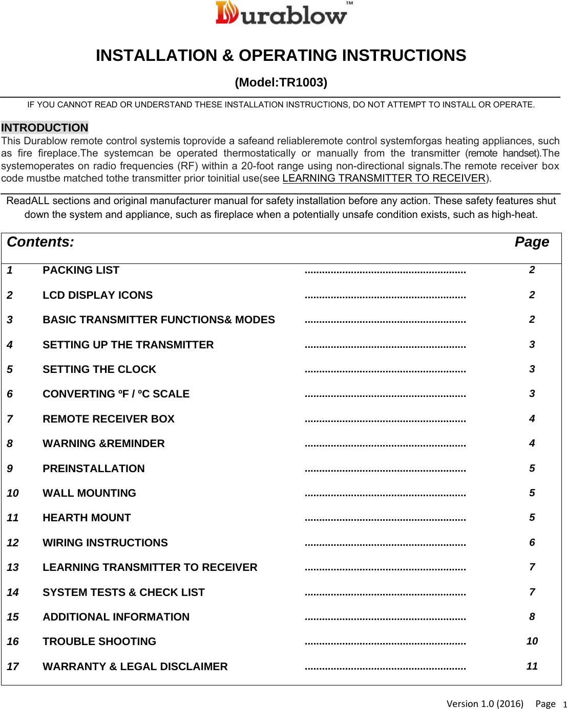
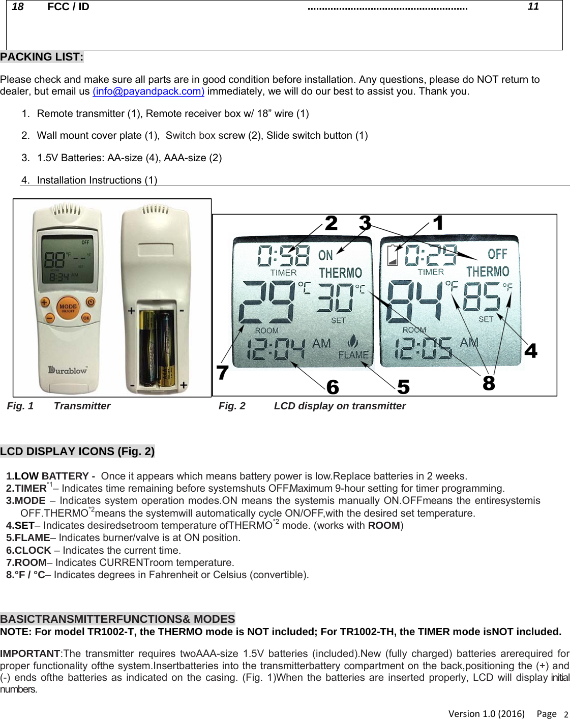
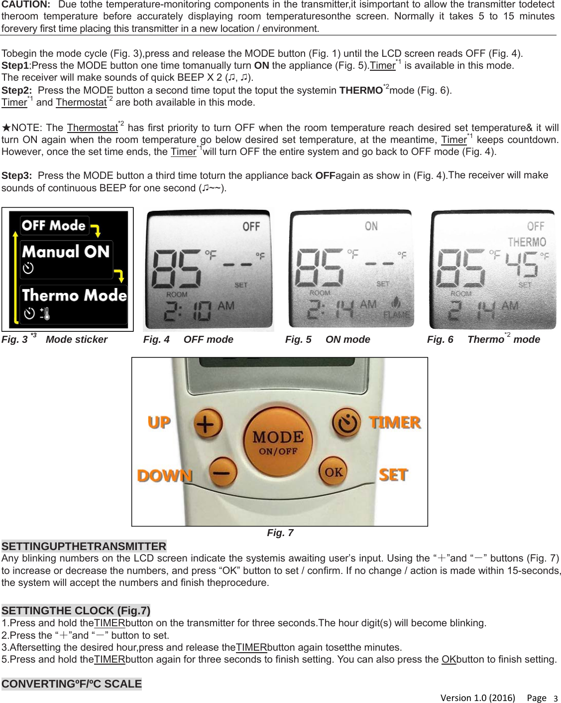
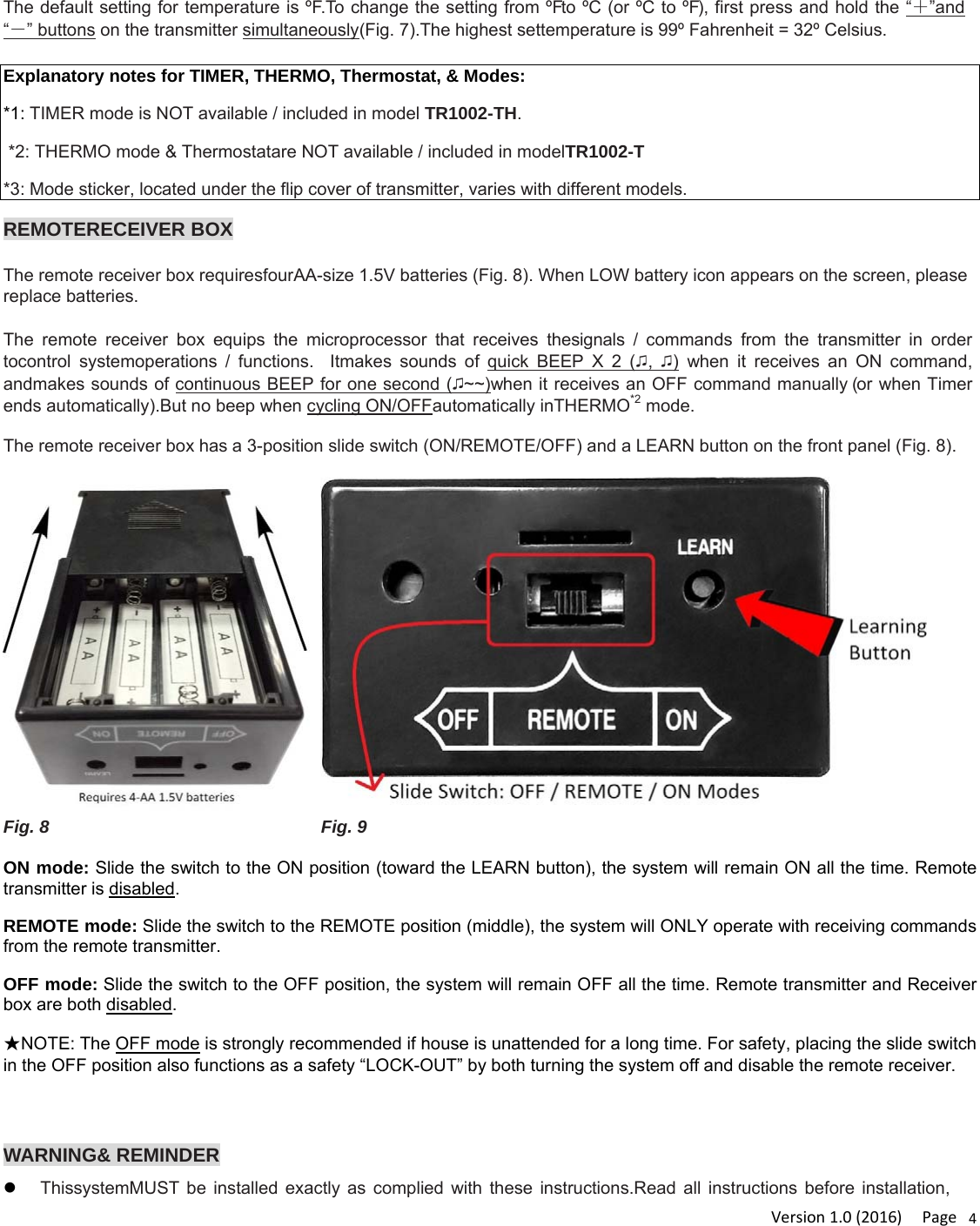
Modern TR1003 Fireplace remote control transmitter User Manual TR1003 Instructions

Modern Co., Ltd. Fireplace remote control transmitter TR1003 Instructions

User manual

Version1.0(2016)Page1INSTALLATION & OPERATING INSTRUCTIONS (Model:TR1003) IF YOU CANNOT READ OR UNDERSTAND THESE INSTALLATION INSTRUCTIONS, DO NOT ATTEMPT TO INSTALL OR OPERATE. INTRODUCTION This Durablow remote control systemis toprovide a safeand reliableremote control systemforgas heating appliances, such as fire fireplace.The systemcan be operated thermostatically or manually from the transmitter (remote handset).The systemoperates on radio frequencies (RF) within a 20-foot range using non-directional signals.The remote receiver box code mustbe matched tothe transmitter prior toinitial use(see LEARNING TRANSMITTER TO RECEIVER).  ReadALL sections and original manufacturer manual for safety installation before any action. These safety features shut down the system and appliance, such as fireplace when a potentially unsafe condition exists, such as high-heat. Contents: Page 1  PACKING LIST ........................................................  2 2  LCD DISPLAY ICONS ........................................................  2 3  BASIC TRANSMITTER FUNCTIONS& MODES ........................................................  2 4  SETTING UP THE TRANSMITTER ........................................................  3 5  SETTING THE CLOCK ........................................................  3 6  CONVERTING ºF / ºC SCALE ........................................................  3 7  REMOTE RECEIVER BOX ........................................................  4 8  WARNING &REMINDER ........................................................  4 9  PREINSTALLATION ........................................................  5 10  WALL MOUNTING ........................................................  5 11  HEARTH MOUNT ........................................................  5 12  WIRING INSTRUCTIONS ........................................................  6 13  LEARNING TRANSMITTER TO RECEIVER ........................................................  7 14  SYSTEM TESTS & CHECK LIST ........................................................  7 15  ADDITIONAL INFORMATION ........................................................  8 16  TROUBLE SHOOTING ........................................................  10 17  WARRANTY & LEGAL DISCLAIMER ........................................................  11
Version1.0(2016)Page218  FCC / ID ........................................................  11     PACKING LIST: Please check and make sure all parts are in good condition before installation. Any questions, please do NOT return to dealer, but email us (info@payandpack.com) immediately, we will do our best to assist you. Thank you. 1.  Remote transmitter (1), Remote receiver box w/ 18” wire (1) 2.  Wall mount cover plate (1),  Switch box screw (2), Slide switch button (1) 3.  1.5V Batteries: AA-size (4), AAA-size (2) 4. Installation Instructions (1) Fig. 1       Transmitter  Fig. 2          LCD display on transmitter  LCD DISPLAY ICONS (Fig. 2) 1.LOW BATTERY -  Once it appears which means battery power is low.Replace batteries in 2 weeks. 2.TIMER*1– Indicates time remaining before systemshuts OFF.Maximum 9-hour setting for timer programming. 3.MODE – Indicates system operation modes.ON means the systemis manually ON.OFFmeans the entiresystemis OFF.THERMO*2means the systemwill automatically cycle ON/OFF,with the desired set temperature. 4.SET– Indicates desiredsetroom temperature ofTHERMO*2 mode. (works with ROOM) 5.FLAME– Indicates burner/valve is at ON position. 6.CLOCK – Indicates the current time. 7.ROOM– Indicates CURRENTroom temperature. 8.°F / °C– Indicates degrees in Fahrenheit or Celsius (convertible).   BASICTRANSMITTERFUNCTIONS& MODES NOTE: For model TR1002-T, the THERMO mode is NOT included; For TR1002-TH, the TIMER mode isNOT included. IMPORTANT:The transmitter requires twoAAA-size 1.5V batteries (included).New (fully charged) batteries arerequired for proper functionality ofthe system.Insertbatteries into the transmitterbattery compartment on the back,positioning the (+) and (-) ends ofthe batteries as indicated on the casing. (Fig. 1)When the batteries are inserted properly, LCD will display initial  numbers.
Version1.0(2016)Page3CAUTION:  Due tothe temperature-monitoring components in the transmitter,it isimportant to allow the transmitter todetect theroom temperature before accurately displaying room temperaturesonthe screen. Normally it takes 5 to 15 minutes forevery first time placing this transmitter in a new location / environment.  Tobegin the mode cycle (Fig. 3),press and release the MODE button (Fig. 1) until the LCD screen reads OFF (Fig. 4). Step1:Press the MODE button one time tomanually turn ON the appliance (Fig. 5).Timer*1 is available in this mode.  The receiver will make sounds of quick BEEP X 2 (♫, ♫). Step2:  Press the MODE button a second time toput the toput the systemin THERMO*2mode (Fig. 6). Timer*1 and Thermostat*2 are both available in this mode.   ★NOTE: The Thermostat*2 has first priority to turn OFF when the room temperature reach desired set temperature& it will turn ON again when the room temperature go below desired set temperature, at the meantime, Timer*1 keeps countdown. However, once the set time ends, the Timer*1will turn OFF the entire system and go back to OFF mode (Fig. 4).  Step3:  Press the MODE button a third time toturn the appliance back OFFagain as show in (Fig. 4).The receiver will make sounds of continuous BEEP for one second (♫~~).    Fig. 3 *3     Mode sticker  Fig. 4     OFF mode Fig. 5     ON modeFig. 6     Thermo*2mode  Fig. 7 SETTINGUPTHETRANSMITTERAny blinking numbers on the LCD screen indicate the systemis awaiting user’s input. Using the “+”and “-” buttons (Fig. 7) to increase or decrease the numbers, and press “OK” button to set / confirm. If no change / action is made within 15-seconds, the system will accept the numbers and finish theprocedure.  SETTINGTHE CLOCK (Fig.7) 1.Press and hold theTIMERbutton on the transmitter for three seconds.The hour digit(s) will become blinking. 2.Press the “+”and “-” button to set. 3.Aftersetting the desired hour,press and release theTIMERbutton again tosetthe minutes. 5.Press and hold theTIMERbutton again for three seconds to finish setting. You can also press the OKbutton to finish setting.  CONVERTINGºF/ºC SCALE
Version1.0(2016)Page4The default setting for temperature is ºF.To change the setting from ºFto ºC (or ºC to ºF), first press and hold the “+”and “-” buttons on the transmitter simultaneously(Fig. 7).The highest settemperature is 99º Fahrenheit = 32º Celsius.  Explanatory notes for TIMER, THERMO, Thermostat, & Modes: *1: TIMER mode is NOT available / included in model TR1002-TH.  *2: THERMO mode & Thermostatare NOT available / included in modelTR1002-T *3: Mode sticker, located under the flip cover of transmitter, varies with different models.  REMOTERECEIVER BOX  The remote receiver box requiresfourAA-size 1.5V batteries (Fig. 8). When LOW battery icon appears on the screen, please replace batteries.  The remote receiver box equips the microprocessor that receives thesignals / commands from the transmitter in order tocontrol systemoperations / functions.  Itmakes sounds of quick BEEP X 2 (♫,  ♫) when it receives an ON command, andmakes sounds of continuous BEEP for one second (♫~~)when it receives an OFF command manually (or when Timer ends automatically).But no beep when cycling ON/OFFautomatically inTHERMO*2 mode.  The remote receiver box has a 3-position slide switch (ON/REMOTE/OFF) and a LEARN button on the front panel (Fig. 8).   Fig. 8  Fig. 9  ON mode: Slide the switch to the ON position (toward the LEARN button), the system will remain ON all the time. Remote transmitter is disabled.  REMOTE mode: Slide the switch to the REMOTE position (middle), the system will ONLY operate with receiving commands from the remote transmitter. OFF mode: Slide the switch to the OFF position, the system will remain OFF all the time. Remote transmitter and Receiver box are both disabled.  ★NOTE: The OFF mode is strongly recommended if house is unattended for a long time. For safety, placing the slide switch in the OFF position also functions as a safety “LOCK-OUT” by both turning the system off and disable the remote receiver.   WARNING& REMINDER  ThissystemMUST be installed exactly as complied with these instructions.Read all instructions before installation,
Version1.0(2016)Page5and follow them during installation carefully. Any modifications of Durablow remote control system, or parts, or components are PROHIBITED. They will void the warranty, and may cause a fire hazard result in human casualties and property damages. Do NOT connect any gas valve or electronic module directly to110-120VAC power.   Read gas appliance manufacturer’s instructions and wiring schematics completely forproper placement ofall wires.All electronic modules are tobe wired to manufacturer’s specifications. All wiring diagrams in these instructions are forillustration purpose ONLY.Follow instructions from manufacturers ofgas valve andelectronic module forcorrect wiring & installation procedures. Improper installation ofelectric components can cause damage to electronic module, gas valve and remote receiver.  PREINSTALLATION Decide where to install the receiver box before proceeding.The receiver is designed to be wall-mounted into astandard wall switch box (STRONGLY SUGGESTED).   Otherwise, you canplace it on or near the fireplace hearth(*IMPORTANT: Keep away from high-heat, exceeding 130°F. Additional protection required for no exposure to the hearth).  WALLMOUNTING  Make sure the receiver box’s slide switch is in theOFFposition before installation. The receiver is connected with 18-inches ofblack wire.  If additional length of wire is required, for the best results, 18 gauge stranded or solid wire are recommended.Splice with the original black wires ofthe receiver box. Or, remove the black wires and insertnew wires directly intothe slots at back of receiver box (Fig, 10).Wires are NOT longer than 20-feet. Please allow some wire / space toremove the receiver for battery replacement or check. Fig. 10        Fig. 11 Fig. 12  Fig. 13
Version1.0(2016)Page61.  Install fourAA-size 1.5V batteries into the remote receiver box(Fig 8).The systemoperates wellwithall batteries’total output voltage is greater than 5.2V. Generally, four NEWAA-size batteries should output voltage of6.0 to6.2 volts if installed in series.  2.  Attach wall mount cover plate toreceiver box (Fig. 11). Press the receiver and haveit snap into top& bottom tabs ofcover plate.  3.  Position the cover plate to have words facing up (Fig. 12) Install the remote receiver box into the wallswitch boxwithtwo provided switch box long screws.NOTE:The remote receiver box will only receivesignal fromthe transmitter in the REMOTEposition(middle). The remote receiver box code mustbe matched tothe transmitter prior toinitial use (see LEARNING TRANSMITTER TO RECEIVER).  HEARTHMOUNT  The remote receiver box can be placed on the fireplace, under the fireplace, behind the control panel orlouvers....etc.Keep away from high-heat, exceeding 130°F. Additional protection required for no exposure to the hearth.TheSlide switch button should be installed on the receiver box forHearth Mount (Fig. 13).  WIRINGINSTRUCTIONS  ONLYqualified electrician / gas technician with the knowledge of gas appliances and gas valves that are permittedto install the remote control system.Incorrect wiring installationwilldamagethe gas valve, electronic module of  gas appliance and also the remote receiver.  a.  WIRING MILLIVOLT VALVE (Fig. 14)  Connect the two 18 gauge stranded or solid wires of the Remote receiver box to the Millivolt gas valve at the TH & TH/TP terminals on the terminal block. It does not matter which wire go to which terminal. The remote receiver box‘s operation is similar to a thermostat that also turn the gas valve ON and OFF based on the input signals from TH & TH/TP terminals. Transmitter sends signals to receiver box, and receiver box pass the signals to Millivolt valve to function the ON and OFF of fire / heater.  Fig. 14  b.  WIRING ELECTRONIC SPARK IGNITION MODULE (Fig. 15)  Connecta 24VAC transformer in series to the TR (transformer) terminal on the ELECTRONIC MODULE.  Connect the hot wire from the 24VAC transformer to either of the wire terminals on the remote receiver box. Connect another wire
Version1.0(2016)Page7betweenreceiver wire terminal and the TH (thermostat) terminal on the ELECTRONIC MODULE. Fig. 15  LEARNINGTRANSMITTERTORECEIVEREach transmitter has a unique RF code. To have the receiver box to accept the transmitter’s signal(code), be sure the slide switch button on the receiver is in the REMOTE mode.   Find the LEARN button on the front face of the receiver (Fig. 16) Use a small screw- drivergently press the black LEARN button insidethe hole. Then the receiver box will sounds of quick BEEP X 2 (♫,  ♫). And press theMODE button on transmitter . The receiver box willbeeps indicating that the transmitter’s code has been captured by the receiver.  If you fail the LEARNING of matching the security code, please wait 2 minutes before another try.The interval allows the microprocessor in the receiver box toreset itself and available for accepting new code. Please try more times. Any questions, please email us. (info@payandpack.com)  Fig. 16   SYSTEMTESTS & CHECK LIST
Version1.0(2016)Page8 MILLIVOLTVALVES  Please DO take following tests and make sure all functions are working fine:  1.  Slide the slide switch button on the receiver to the ON (Fig. 16). The main gas fire flame should ON.  2.  Slide the button to OFF. The main gas fire flame should extinguish and the pilot flame will remain ON.  3.  Slide the button to REMOTE, and press the MODE button on the transmitter to change the system to ON. The main gas fire flame should ON.  4.  Press the MODE button on the transmitter to change the system to OFF.The main gas fire flame should extinguish and the pilot flame will remain ON.  5.  Press the MODE button on the transmitter to change the system to THERMO*2 mode. Make the SET temperature on the transmitter to a temperature of a least 2°F (1°C) above the ROOM temperature displayed on the LCD screen, the system flame and main gas fire flame will be ON. Then make the SET temperature to at least 2°F (1°C) below the ROOM temperature, the system flame and main gas fire flame will extinguish in seconds. It should continue to cycle ON and OFF thermostatically. The temperature differential between ROOM and SET temperatures differ at least 2°F (1°C) to start the THERMO*2 cycling. (The 2°F differential is the factory setting, can NOT be changed.)
9ELECTRONICIGNITIONSYSTEMS Please DO take following tests and make sure all functions are working fine: 1.  Slide the slide switch button on the receiver to the ON (Fig. 16). The spark igniting electrode should begin sparking to ignite the pilot. Once the pilot flame is lit, the main gas valve should open and the main gas fire flame should be ON. 2.  Slide the button to OFF. The main gas fire flame and pilot fire flame should extinguish together. 3.  Slide the button to REMOTE, and then press the MODE button on the transmitter to change the system to ON. The spark igniting electrode should begin sparking to ignite the pilot. Once the pilot flame is lit, the main gas valve should open and the main gas fire flame should be ON. 4.  Press the MODE button to OFF. The main gas fire flame and pilot fire flame should extinguish together. 5.  Press the MODE button on the transmitter to change the system to THERMO*2. Make the SET temperature on the transmitter to a temperature of a least 2°F (1°C) above the ROOM temperature displayed on the LCD screen, the system flame and main gas fire flame will be ON. Then make the SET temperature to at least 2°F (1°C) below the ROOM temperature, the system flame and main gas fire flame will extinguish in seconds. It should continue to cycle ON and OFF thermostatically. The temperature differential between ROOM and SET temperatures differ at least 2°F (1°C) to start the THERMO*2 cycling. (The 2°F differential is the factory setting, can NOT be changed.)   ADDITIONALINFORMATION THERMOSAFETYPROTECTION FORRECEIVER  In order to protect the receiver box, batteries, and receiver’s microprocessors, the Durablow remote control system equips a THERMISTOR, a safety feature in receiver box. The THERMISTOR will automatically shut the system and appliance down,& begin makingBEEP X 3 (♫, ♫, ♫), every 4 seconds, when the temperature inside the receiver boxis higher than 130°F (54°C). User can re-activate the system by pressing the MODE button on the transmitter when  the  receiver temperature drops between 120°F (48°C) and 130°F (54°C). However, the BEEPING will NOT stop if the temperature remains between 120°F and 130°F until the temperature drops below 120°F. The beeping is to alert user that the receiver should be re-located at a cooler position. To completely reset the beeping and THERMISTOR,  please press the MODE button to make a mode cycle (OFF-ON-OFF). Please make sure & allow some time for the receiver box to cool down below 120°F .    TRANSMITTER  1.  TRANSMITTEROPERATINGDISTANCE  Thetransmitter uses RF radio frequency to send signal to receiver. Itis strongly recommendedtouse thetransmitter within20-foot distance from receiver box in the same room / space (no wall partition).  2. THERMO*2DETECTING INTERVAL IN TRANSMITTER The transmitter normally detects the ROOMtemperature every 2 minutes against theSETtemperature by sending a signal tothe receiver.  3.  OUT-OF-RANGE SAFETY ALERT IN TRANSMITTER   Page8
10This Durablow remote control system have a OUT-OF-RANGE SAFETY ALERT function whichalerts when the transmitter is out of the normal 20-foot operating range of the receiver for all operation modes. The transmitter sends an RF signal every fifteen minutes to the receiver box to indicate that the transmitter is within the normal operating range of 20-foot.  If the receiver does NOT receive a signal every 15 minutes from transmitter, the receiver will begin a 120-minute countdown.  If during this period, the receiver does NOT receive a signal from the transmitter, the receiver will shut down the system (OFF). Then thereceiver will beeps rapidly for 10 seconds, and after that, the receiver will continue to beep (single beep) every4 seconds until a transmitter signal is again received.Press the MODE button on the transmitter to reset the receiverand the system will be back to normal operation. The OUT-OF-RANGE SAFETY ALERT will betriggered when the transmitter is out of rangeagain or the transmitter’s low battery, batteries fail,batteries removed. SETTING THE DESIRED ROOM TEMPERATURE To set the DESIRED room temperature, press the MODE button to place transmitter into THERMO*2 mode (Fig. 6), the “THERMO”*2 must be displayed on the LCD screen. Then press the “+” and “-” buttons to increase or decrease desired room temperature. The MAX. set temperature is 99° F (32° C), MIN. is 45° F (6° C).REMINDING: Toextend battery lifespan, the changes of ROOM temperature are detected and updated (send) to transmitter automaticallyevery two minutes only. TEMPERATURE DIFFERENTIAL (variation “SWING”) The THERMO*2mode on the transmitter operates with TEMPERATURE DIFFERENTIAL (also called variation “SWING”). A smaller SWING increases the number of cycles so the room temperature is updated more often which consume more battery power. A larger SWING decreases the number of cycles, so the tolerance of ROOM temperature is larger, but can save some battery. The factory default setting for the SWING is 2 which means a temperature variation of +/- 2°F (1°C) between SET temperature and ROOM temperature, which determines when the system will be ON or OFF. There are threeSWING numbers for user’s choice:  +/- 1°F (0.5°C), +/- 2°F (1°C) , and +/- 3°F (1.6°C). See Fig. 17  Fig. 17  Fig. 18                                                        Page9
11SETTING THE SWING 1. To change the temperature SWING setting, press theTIMER and “-” buttons(Fig. 18) at the same timeto display the current SWING setting (Fig. 17). The letter “S” (looks like Arabic number “5”) means you are currently in the SWING setting,   2. Press the “+”and “-” buttons to change the SWING(1, 2 , 3).  3. To store the desired SWING number, press the OK button or wait for 15 seconds without any actions, then transmitter will accept the setting and become programmed.  SETTING THE COUNTDOWN TIMER*1 The TIMER*1 is available in the ON or THERMO*2modes on transmitter (THERMO or ON must be displayed on the screen). 1.  Press  the TIMER button (Fig. 18) on the transmitter.The word TIMER*1 will be displayed and “0:15” minutes (factory default setting) will be blinking on the screen (Fig. 19). 2. Press the “+”and “-” buttons on the transmitter to set the countdown time. Available countdown time options are 15 minutes, 30 minutes,1 hour (1:00), 1:30, 2:00, 2:30, 3:00, 3:30 ............. 8:30, 9:00. 3. To confirm the TIMER*1, press the OK button or wait for 15 seconds without any actions, then transmitter will accept the setting and become programmed. If the system is cycling in the THERMO*2 mode + TIMER*1 feature, it will cycle on and off, as the room temperature requires until the “time” has expired.  Fig. 19                     Fig. 20  CHILDPROOF FEATURE& SETTING Asafety LOCK feature is available from the TRANSMITTER. 1. To activate the LOCK, press and hold the “+” and TIMERbuttons together for 5-7 seconds. The“CP” will appear in the ROOM temperature on the screen (Fig. 20). CP word will disappear in one second but the CP lock is activated. 2. To deactivate the LOCK, press and hold the “+” and TIMERbuttons together for 5-7 seconds. The“CP” will disappear and the transmitter will be unlocked and back to normal operating condition. NOTE: The CHILDPROOF FEATURE (CP-LOCK) will NOT cancel the operating and cycling of ON, TIMER*1, THERMO*2. In order to “TOTAL” lock-out the system, please activate CP-LOCK in OFF mode on transmitter.  Page10
12TROUBLE SHOOTING Problems with different fireplace systems are NOT just caused by Durablow remote control, but also by fireplace itself. Please firstly review and check fireplace manufacturer’s manual to see if all wires are properly connected, valve is working fine, or gas tank / pipes are in good condition. Then please check the operations below:  1. Check to see if receiver batteries are installed properly. If one battery is installed backward, the entire system will NOT working. Be sure battery output is 2.5 volts or more for transmitter, and 5.2 volts or more for receiver box. 2. Make sure the transmitter is communicating with the receiver. Check to see if receiver beepsin ON & OFF modes.  The receiver only beeps in ON & OFF modes. If no beeps when the MODE button is depressed on the transmitterin ON & OFF modes, please LEARN and match transmitter with receiver first (see LEARNING TRANSMITTER TO RECEIVER). 4. Make sure the transmitter is in good condition (doused or broken transmitter will be out of order) and within the 15 to 20-foot range of the receiver. 5. Positioning the receiver box is quite important.  If the receiver is fully coveredby a metal, the operation of thereceiver may be failed because of losing communicating with transmitter or shortening the use distance range. Re-position the receiver to gain better signals.   WARRANTY & LEGAL DISCLAIMER Warranty: Durablowwarrants thisremote control system for a 2-YEAR LIMITED WARRANTY of the original purchaser / owner of this system. This warranty is not transferable to another person. it is for the original purchaser of the product.  Durablowwarrants any parts failed because of defective workmanship in production or materials from the original date of purchase. Durablow will repair or replace the defective parts at Durablow’sdecision. Replacement parts will be available at NO chargesand free-shipping to users for the FIRST2 years of this warranty. If Durablow does not have the parts for a certain model, then a replacement system will be provided. The Owner must provide a bill of sale, order ID or payment record which should be kept to verify purchase date and establish warranty period.  This warranty does not cover claims. Damage to the system caused by accident, misuse, abuse, or installation error, no matterimplemented by acontractor, third party Service Company, or owner, is not covered by this warranty. Any modifications of the system will void this warranty. Photos and simple questions may be required for further product investigation & improvement. Durablow & PayandPack will reserve the right to physically inspect the product for defects, by authorized representatives. Legal disclaimer: Due to different using circumstance, user should take specific advice from qualified technician or professional people before undertaking any action following information included in these instructions above. All users who ignore this disclaimer, misuse, abuse, or install the system improperly are at their own risk.
13FCC / ID FCC STATEMENT This device complies with Part 15 of the FCC rules. Operation is subject to the following two conditions: 1) this device may not cause harmful interference, and 2) this device must accept any interference received, including interference that may cause undesired operation. Changes or modifications not expressly approved by the party responsible for compliance could void your authority to operate the equipment. NOTE: This equipment has been tested and found to comply with the limits for a Class B digital device, pursuant to Part 15 of the FCC Rules. These limits are designed to provide reasonable protection against harmful interference in a residential installation. This equipment generates uses and can radiate radio frequency energy and, if not installed and used in accordance with the instructions, may cause harmful interference to radio communications. However, there is no guarantee that interference will not occur in a particular installation. If this equipment does cause harmful interference to radio or television reception, which can be determined by turning the equipment off and on, the user is encouraged to try to correct the interference by one or more of the following measures:  Reorient or relocate the receiving antenna.   Increase the separation between the equipment and receiver.   Connect the equipment into an outlet on a circuit different from that to which the receiver is connected.   Consult the dealer or an experienced  radio/TV technician for help.  FCC ID: 2AKOB-TR1003  CUSTOMER SUPPORT: Any questions, please contact and email us before returning items or leaving a feedback / review. We will always be here for you. Reach us on eBay, Amazon, www.payandpack.com or email (info@payandpack.com). Thank you. ^_^ Page11

Navigation menu