Mojo Networks SS300ATC60 SpectraGuard Access Point / Sensor User Manual SS 300AT C 60 UserMan Part5
AirTight Networks, Inc. SpectraGuard Access Point / Sensor SS 300AT C 60 UserMan Part5
Contents
- 1. Users Manual
- 2. Users Manual-1
- 3. Users Manual-2
- 4. Users Manual-3
- 5. Users Manual-4
- 6. Users Manual-5
- 7. Users Manual-6
- 8. (SS-300AT-C-60) UserMan-Part1_2013.12.11 revised
- 9. (SS-300AT-C-60) UserMan-Part2
- 10. (SS-300AT-C-60) UserMan-Part3
- 11. (SS-300AT-C-60) UserMan-Part4
- 12. (SS-300AT-C-60) UserMan-Part5
- 13. (SS-300AT-C-60) UserMan-Part6
(SS-300AT-C-60) UserMan-Part5
Administration Tab
SpectraGuard® Enterprise User Guide
221
View Logs
Recommendation: In order to properly view the multilingual characters, download the log file in .TSV format and
view it in Excel.
In the log file, different log records are listed in different rows. For each row, following columns are provided:
Date (UTC): Specifies the date and the time of the record in UTC format
Module: Specifies if the user action was performed from the Console (GUI), API, or the Config Shell (CLI)
Host Address: Specifies the IP Address/Client Name/API Client Identifier/Hostname from where the system
was accessed by the user
Role: Specifies the role of the user
Login Name: Specifies the login name of the user whose action has triggered the specific log record
Type: This column indicates the type of record. Type is one of: Access, Devices, Events, Reports, Location Tree,
Local Settings, Global Settings, Start/Stop Functions, System, Others.
Status: This column indicates if the record pertains to success or failure of the action.
Message: Describes the record in detail.
Upgrade
Upgrade the Server
The system enables you to upgrade the existing version of the server to a newer version, if available. This section
describes the steps to upgrade the server working in Standalone mode. For steps to upgrade the server working in
High availability (HA) mode, refer to the High Availability Configuration Guide.
Administration Tab
SpectraGuard® Enterprise User Guide
222
Select the check box, Check for availability of Server upgrade at each login, to enable the system automatically
check if an upgrade is available when you log into the console.
Upgrade
If you have modified the Upgrade Link, to save it click <Apply> on the Upgrade screen.
To check if an upgrade is available for the server, click <Check for Upgrade Now>.
If an upgrade is available, an Upgrade Available dialog appears.
Upgrade Available Dialog
Click the hyperlink, support center, to go to the AirTight® Networks Support Portal, from where you can download
the server upgrade bundle.
Administration Tab
SpectraGuard® Enterprise User Guide
223
Click OK or close the dialog to close the Upgrade Available dialog. Alternatively, click Ignore Upgrade Notification
to ignore the upgrade notification until you log out of the Console.
If an upgrade is not available, an Upgrade Not Available dialog appears. Click <OK> to close the dialog.
Upgrade Not Available Dialog
Upgrade SpectraGuard Enterprise Now
Prerequisites:
1 Sun Java Runtime Environment (JRE) version 1.6 update 22 or above must be installed on the computer from
where you access the Console.
2 Popup blockers on the computer from which the Console is accessed must allow popup windows from the
server.
3 If there is a firewall between the computer from which the Console is accessed and the server, TCP port 8080 of
the server must be accessible from that computer.
4 Users with the ‘Superuser’ user role only can initiate server upgrade using this method.
Recommended: To upgrade the server to a higher version, ensure that you access the Console using a computer
whose IP address is not behind Network Address Translation (NAT). If you access the Console, using a NATed IP,
upgrade will continue in the background but you cannot view the upgrade progress messages.
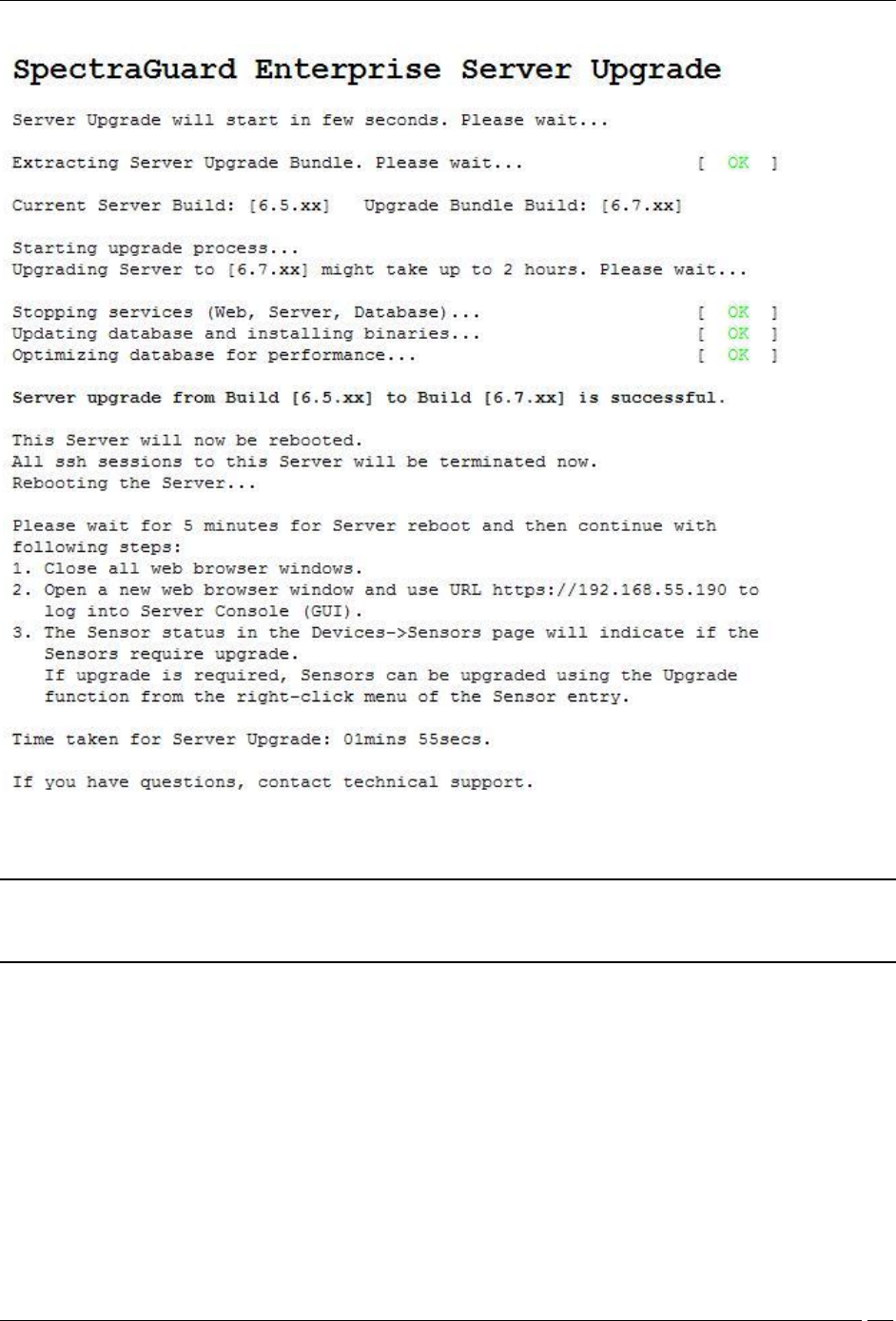
Steps for Server Upgrade
1 Click Browse to select the Upgrade Bundle.
2 Click Upgrade Now to transfer the Upgrade Bundle to the server.
3 On the Confirm Upgrade dialog, click Yes to proceed with the upgrade.
Confirm Upgrade Dialog
4 The Uploading Upgrade Bundle message with the progress bar appears.
Administration Tab
SpectraGuard® Enterprise User Guide
224
Uploading Upgrade Bundle Progress Bar
5 You can cancel the upgrade by clicking Cancel anytime while the Upgrade Bundle upload is in progress.
6 After the Server Upgrade Bundle upload is complete, Server Upgrade starts automatically.
7 Close the current browser window. A new window, Server Upgrade Progress, is launched which displays the
status of the Server Upgrade process. Follow the instructions displayed on the Server Upgrade Progress window.
Administration Tab
SpectraGuard® Enterprise User Guide
225
Server Upgrade Progress Window
Note: You cannot abort or cancel the Server Upgrade process once the Server Upgrade Progress window is
launched. Additionally, the Server Upgrade process continues even if the Server Upgrade Progress window is
closed.
8 After the server upgrade is successful, the server reboots automatically.
9 After you have read all instructions on the Server Upgrade Progress window, close all the Web browser
windows including the Server Upgrade Progress window.
10 Wait for five minutes for the server to reboot. After this, you can access the server again.
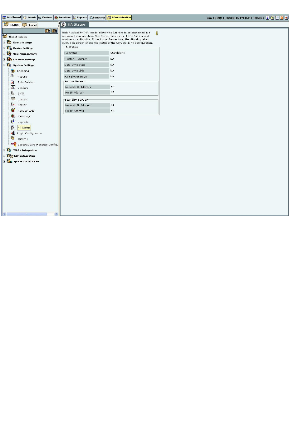
High Availability
High Availability (HA) mode allows two servers to be connected in a redundant configuration to form an HA cluster.
One server acts as the Active server, while the other as a Standby server. If the Active server fails, the Standby server
takes over. This screen shows the status of the servers in HA cluster.
Administration Tab
SpectraGuard® Enterprise User Guide
226
HA Status
HA Status: This is a read-only section and displays the following information:
HA Status: Displays the status of the HA Cluster.
Standalone: This state indicates that the server is in Standalone mode.
Up: This state indicates that the HA Cluster is up and running.
Other Server Not Reachable: This state indicates that the Standby server is not reachable over the HA
interface link. Check whether the HA interfaces of both the servers are securely connected using a crossover
Ethernet cable.
Temporarily In Transition: This is an intermediate state. You need to wait for up to 30 minutes and then
check the HA Status again. If this state persists, contact Technical Support.
HA Setup In Progress: This state indicates that an HA setup is in progress using Config Shell or an
earlier HA setup session was abnormally terminated. If you are sure HA setup is not in progress, reboot both
the servers. After reboot, both the servers come up in the 'Standalone' mode. You need to wait for five
minutes after the reboot and then login to these servers.
Server Upgrade In Progress: This state indicates that server Upgrade is in progress or an earlier server
Upgrade session was abnormally terminated. If you are sure server Upgrade is not in progress, reboot the
server. After reboot, the server will come up in the 'Standalone' mode. You need to wait for five minutes after
the reboot and then login to the server.
Database Operation In Progress: This state indicates that some database operation is in progress. If you
are sure no database operation is in progress, please contact Technical Support.
Internal System Recovery In Progress: This state indicates that internal system recovery is in progress.
If the same state persists for more than 30 minutes, please ensure that both the HA servers are up and the HA
interfaces of these servers are securely connected using a crossover Ethernet cable. If the same state persists
even after the above checks, please contact Technical Support.
Administration Tab
SpectraGuard® Enterprise User Guide
227
Error: This state indicates an error in HA state. Contact Technical Support.
Cluster IP Address: This IP Address can be used by the Console and Sensors to connect to the HA cluster. This
is a virtual IP Address used to connect to the HA cluster. Cluster IP address is optional. It can not be used in Layer3
HA configuration.
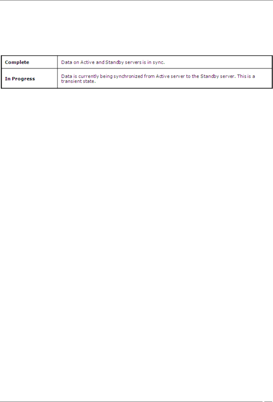
Data Sync State: Displays the state of data synchronization from Active Server to Standby Server after enabling
HA Service or after database operation such as database restore.
Data Sync Link: Data sync link is the link which carries data from the Active Server to Standby. HA interface or
Network Interface can be used as ‘Data Sync Link’ between the servers. During HA setup, user can skip use of HA
interface.
This field indicates whether two servers are reachable over ‘Data Sync Link’ interface.
HA Failover Mode: Indicates HA failover mode – Automatic/Manual.
Active Server: This section displays IP addresses of the Active server.
Network IP Address: This is the IP Address of the network interface of the Active server.
HA IP Address: This is the IP Address of the HA interface of the Active server.
Standby Server: This section displays IP Addresses of the Standby Server.
Network IP Address: This is the IP Address of the network interface of the Standby server.
HA IP Address: This is the IP Address of the HA interface of the Standby server.
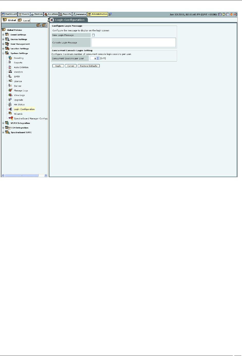
Login Configuration
The system enables you to configure a login message through the Login Configuration screen. Superuser of the
system has the right to enter the login message that will be flashed in the Login screen.
Administration Tab
SpectraGuard® Enterprise User Guide
228
Login Configuration
Under Configure Login Message:
Select the checkbox, View Login Message to show the login message on the Console login page.
Console Login Message: Specifies the login message to display on the Console and on the banner message of
SGE CLI screen.
The Login screen with the specified Console Login Message appears as follows.
Administration Tab
SpectraGuard® Enterprise User Guide
229
Login Screen with the Console Login Message
Under Concurrent Console Login Settings:
Concurrent Sessions per User: Configures the maximum number of concurrent console login sessions per user.
(Minimum: 1, Maximum: 5, Default: 5)
Wizard
The system’s Setup Wizard systematically takes you through a recommended sequence of configuration screens that
enable you to set up your system completely. This wizard does not remember or apply any configuration changes. It
is simply a tour guide. You must explicitly apply changes on the individual configuration screens for them to take
effect. You can exit the wizard or skip a step at any time.
Administration Tab
SpectraGuard® Enterprise User Guide
230
Wizards
Click Start Setup Wizard to open a Confirm message dialog that confirms your navigation through the wizard.
SpectraGuard Manager Configuration
SpectraGuard Manager establishes a communication channel with SpectraGuard Enterprise through a digital
certificate. Version 6.6 onwards, digital certificate-based authentication replaces the username-password
authentication required to log in to the SpectraGuard Enterprise Console through the SpectraGuard Manager
Console. To use certificate-based authentication, you need to have version 6.6 or above, of both SpectraGuard
Manager and SpectraGuard Enterprise.
The certificate needs to be downloaded first from the SpectraGuard Manager and then added to the SpectraGuard
Enterprise server. Both SpectraGuard Manager and SpectraGuard Enterprise need to have the same certificate to
communicate with each other.
The SpectraGuard Manager Configuration option allows you to add, view or delete the certificate that serves as the
link between SpectraGuard Enterprise server and SpectraGuard Manager.
This is a license-based feature. You will be able to see this option under Administration->Global->System Settings
only if you have the appropriate license.
The following figure displays the SpectraGuard Manager Configuration screen.
Administration Tab
SpectraGuard® Enterprise User Guide
231
SpectraGuard Manager Configuration
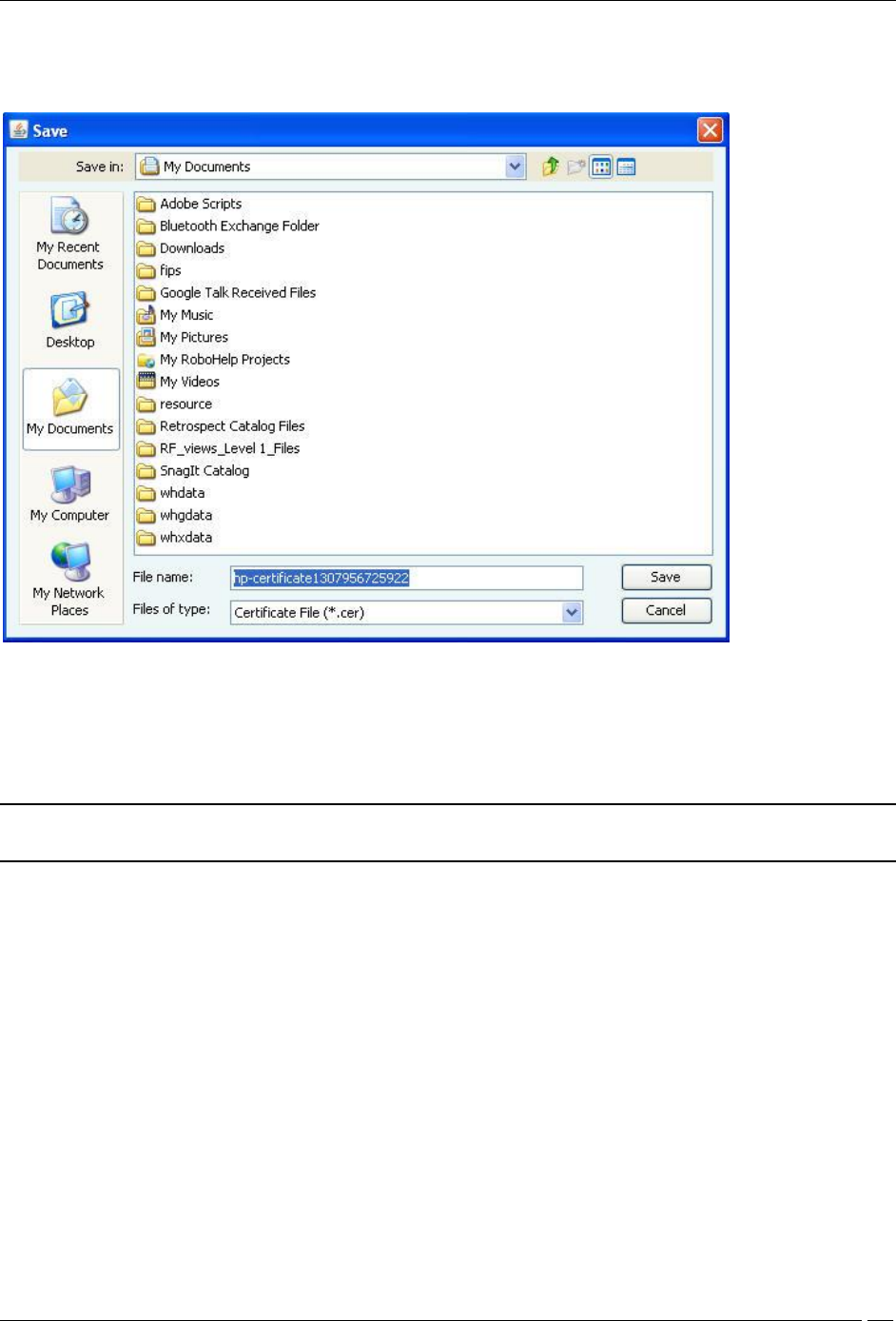
Adding the digital certificate to SpectraGuard Enterprise Server
Before adding the certificate to the SpectraGuard Enterprise server, it must be downloaded from the SpectraGuard
Manager console, and saved to the desired location. To add the certificate to the SpectraGuard Enterprise server,
click Add on the SpectraGuard Manager Configuration screen. Select the certificate from the folder where you have
saved it and add it to the SpectraGuard Enterprise server.
Viewing the digital certificate
Before adding the certificate to the SpectraGuard Enterprise server, it must be downloaded from the SpectraGuard
Manager Console, and saved to the desired location. To view the certificate on the SpectraGuard Enterprise Console,
click the View on the SpectraGuard Manager Configuration screen.
Disassociating the SpectraGuard Enterprise Server from SpectraGuard Manager
To end the association with SpectraGuard Manager, click Disassociate. On clicking Disassociate, the digital
certificate used to communicate with SpectraGuard Manager is deleted from the SpectraGuard Enterprise server.
After the disassociation, the SpectraGuard Enterprise server is no longer able to communicate with the SpectraGuard
Manager.
WLAN Integration
The WLAN Integration dialog enables the system to be integrated with various WLAN Management tools.
Aruba Mobility Controllers
Administration Tab
SpectraGuard® Enterprise User Guide
232
The system integrates with Aruba Mobility Controllers. It fetches wireless device details and RSSI information from
the Aruba Mobility Controllers and thus helps to manage the WLAN infrastructure.
The Aruba WLAN architecture consists of Aruba Mobility Controllers and APs. At any time, the Aruba Mobility
Controller has all the information about the APs and devices seen/associated with these APs.
Integration with Aruba allows the system to fetch this information from Aruba Mobility Controller. Using this
information the system can automatically classify devices managed by Aruba Mobility Controllers, and do location
tracking of devices seen by Aruba APs in sensor-less or sensor and AP mixed environment.
Aruba Integration
Aruba Integration Status: If Aruba integration is enabled, the system obtains data from the configured
mobility controllers, which are individually enabled.
Aruba Integration Enabled: When you select the Aruba Integration Enabled check box, you can
configure Automatic Synchronization Settings. The system disables a mobility controller, by default.
However, automatically enables Aruba integration when you add a new Aruba Mobility Controller.
Current Status: Displays the Current Status of the Aruba mo: Running, In Process or Stopped. An Error
status is shown in one of the following cases:
One of the configured and enabled Aruba Mobility Controllers has a hostname, which cannot be
resolved
One of the configured and enabled Aruba Mobility Controllers is not reachable
System server is stopped
Internal error, in which case you need to contact Technical Support
Imported APs: This percentage indicates total number of APs imported from enabled Aruba mobility
controllers as a fraction of maximum allowed. The maximum allowed depends on type of appliance. The
status displayed is as of the last synchronization event. It is recommended that the utilization remains below
Administration Tab
SpectraGuard® Enterprise User Guide
233
80%. If the utilization exceeds 80%,the system performance may degrade and result in side effects such as
sluggish UI and sensor disconnections.
Under Automatic Synchronization Settings, select the System-Aruba Mobility Controller synchronization
interval.
Synchronization Interval (Minutes): Specifies the interval for which the server synchronizes with the
enabled Aruba mobility controllers
(Minimum: 15 minutes; Maximum: 60 minutes; Default: 30 minutes)
Click Apply to save the changes made to the Aruba Integration dialog.
Click Cancel to cancel the changes made to the Aruba Integration dialog.
Click Restore Defaults to restore the default values for the fields on the Aruba Integration dialog.
Adding an Aruba Mobility Controller
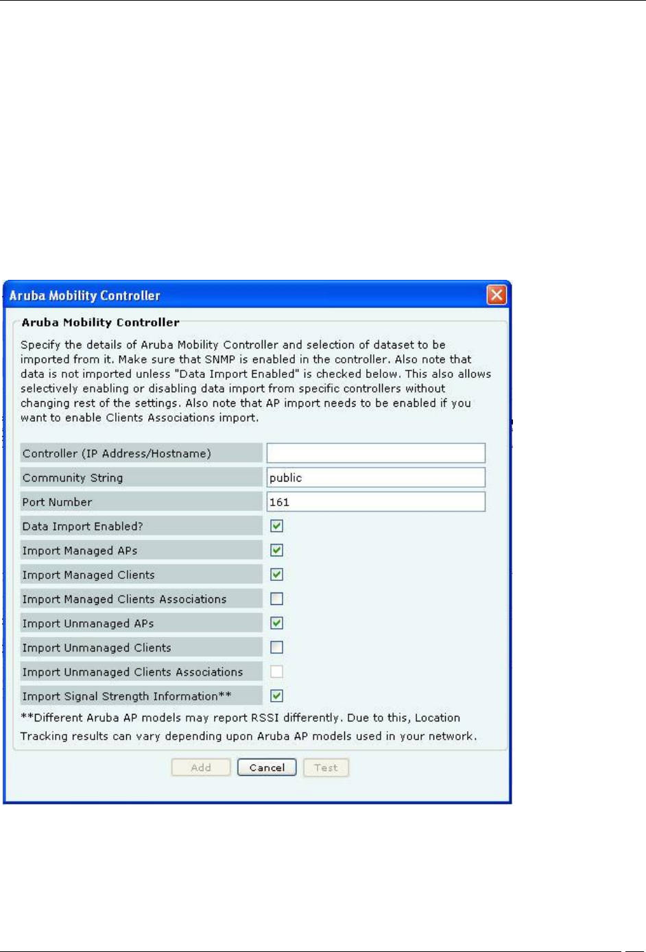
Under Aruba Mobility Controllers, click Add to open Aruba Mobility Controller dialog where you can add Aruba
Mobility Controller details.
Aruba Mobility Controller Dialog
Aruba Mobility Controller contains the following fields:
Controller (IP Address/Hostname): Specifies the IP address or the hostname of the Aruba Mobility Controller
with which the system should communicate.

Administration Tab
SpectraGuard® Enterprise User Guide
234
Note: Configured Aruba Mobility Controllers will use the DNS names and DNS suffixes configured by the user in
the Server Initialization and Setup Wizard on the Config Shell.
Community String: Specifies the user defined community string using which the system communicates with
the Aruba Mobility Controller.
(Default: public)
Port Number: Specifies the port number of the Aruba Mobility Controller from which data is imported.
(Default: 161)
Data Import Enabled?: Indicates if the Aruba Mobility Controller is enabled to communicate with the system,
for data import by the system.
(Default: Selected)
Import Managed APs?: Indicates if the AP’s managed by the Aruba Mobility Controller, are to be imported into
the system.
(Default: Selected)
Import Managed Clients?: Indicates if clients associated with APs managed by the Aruba Mobility Controller
are to be imported into the system.
(Default: Selected)
Import Managed Clients Associations?: Indicates if information related to AP-client association, for AP’s
managed by the Aruba Mobility Controller, is to be imported into the system. This check box is disabled, if Import
Managed Clients check box is deselected.
Import Unmanaged APs?: Indicates if APs not managed by the Aruba Mobility Controller are to be imported
into the system.
(Default: Selected)
Import Unmanaged Clients?: Indicates if Clients associated with APs not managed by the Aruba Mobility
Controller, are to be imported into the system.
(Default: Deselected)
Import Unmanaged Clients Associations?: Indicates if information related to AP-client association, for AP’s
managed by the Aruba Mobility Controller, is to be imported into the system. This check box is enabled, only if
Import Unmanaged Clients check box is selected.
Import Signal Strength Information?: Indicates if the signal strength of the managed devices is to be imported
into the system.
(Default: Enabled)
Note: Location Tracking results may vary depending on the Aruba AP models used in the network.
Click Add to add the details for the new Aruba Mobility Controller. Click Test to confirm the validity of IP
Address/Hostname.
Editing Aruba Mobility Controller settings
Double-click a row to open the Aruba Mobility Controller Dialog similar to the one shown above, to update the
Aruba Mobility Controller details. Alternatively, select a row and click Edit to open the Aruba Mobility Controller
Dialog. Edit the required fields. Click Save to save the changes.
Deleting an Aruba Mobility Controller
Select a row and click Delete to discard the details of an existing Aruba Mobility Controller. You can delete multiple
Aruba Mobility Controller details using click-and-drag or using the <Shift> + <Down Arrow> keys and then clicking
Delete.
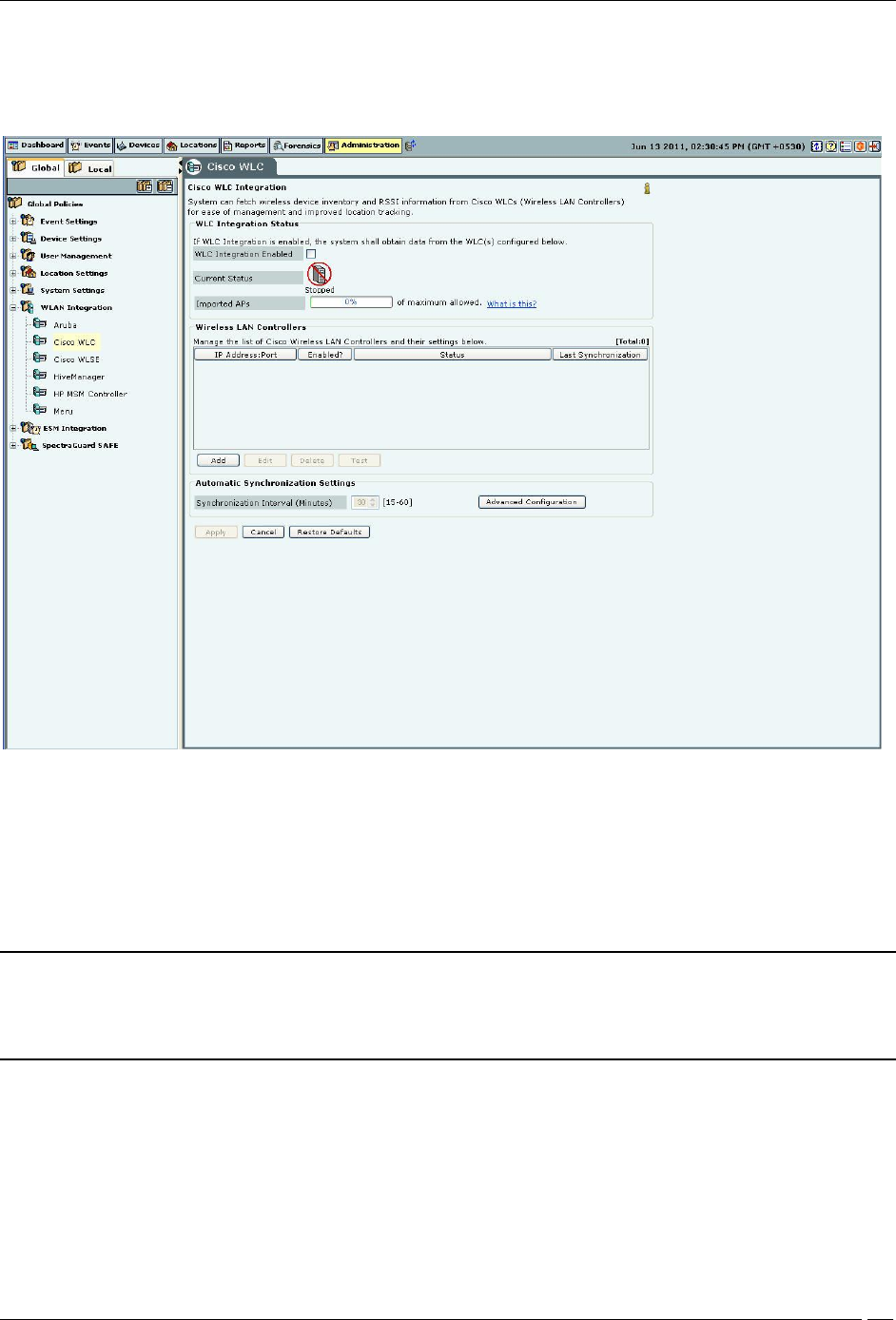
Cisco WLC
The Wireless LAN Controller (WLC) governs a collection of thin AP. LWAPP defines the network protocol between
the APs and WLC. The advantages of this solution are:
Administration Tab
SpectraGuard® Enterprise User Guide
235
Increased scalability
Simplified, centralized management
Zero-touch AP deployment and configuration
Network-wide monitoring
Cisco WLC
The Cisco Unified WLAN architecture consists of Wireless LAN Controllers (WLC) and APs. The APs are managed
using Light Weight Access Point Protocol (LWAPP). At any time, the WLC has all the information about the APs and
devices seen/associated with these APs.
Integration with Cisco WLC allows the system to fetch this information from WLC. Using this information the system
can automatically classify devices managed by WLC and do location tracking of devices seen by LWAPP APs in
sensor-less or sensor and AP mixed environment.
Important: Currently, the system supports the following managed APs: Cisco Aironet 1000 Series, Cisco Aironet
1100 Series, Cisco Aironet 1130 Series, Cisco Aironet 1140 Series, Cisco Aironet 1200 Series, Cisco Aironet 1230
AG Series, Cisco Aironet 1240 AG Series, Cisco Aironet 1250 Series, and Cisco Aironet 1300 Series. The system
supports WLC version 4.2 to 6.0.182.0.
WLC Integration Status: If WLC integration is enabled, the system obtains data from the configured WLCs,
which are individually enabled.
If you select WLC Integration Enabled, you can configure Automatic Synchronization Settings. The system
disables WLC by default. However, automatically enables WLC Integration when you add a new WLC.
Current Status: Displays the Current Status of the WLC: Running or Stopped. An Error status is shown in one of
the following cases:
One of the configured and enabled WLCs has a hostname, which cannot be resolved
One of the configured and enabled WLCs is not reachable
Administration Tab
SpectraGuard® Enterprise User Guide
236
System server is stopped
Internal error, in which case you need to contact Technical Support
Imported APs: This percentage indicates total number of APs imported from WLC(s) as a fraction of maximum
allowed. The maximum allowed depends on type of appliance. The status displayed is as of the last synchronization
event. It is recommended that the utilization remains below 80%. If the utilization exceeds 80%,the system
performance may degrade and result in side effects such as sluggish UI and sensor disconnections.
Under Automatic Synchronization Settings, select the System-WLC synchronization interval.
Synchronization Interval (Minutes): Specifies the interval for which the server synchronizes with the WLC
(Minimum: 15 minutes; Maximum: 60 minutes; Default: 30 minutes)
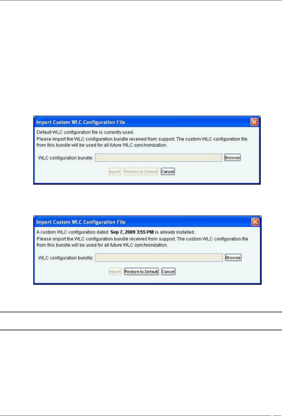
If the customer has some Lightweight Access Points (LAPs) whose type (like ap1030, ap1130) is not supported
by SGE, then these LAPs can be supported by importing the WLC configuration bundle received from the AirTight
Support on request. After the bundle is received, click <Advanced Configuration> The Import Custom WLC
Configuration File dialog appears. The custom WLC configuration file from this bundle is used for all future WLC
synchronization. The bundle is imported as .tgz.
Import Custom WLC Configuration File Dialog
Click Browse to specify the appropriate location of the WLC Configuration bundle and click <Import>, a progress bar
appears. After the file is imported, the date and time when file was imported is displayed as in the screen.
Import Custom WLC Configuration File Dialog showing date and time of the file imported
If the file is not imported for some reason or if the file is corrupted, an error message is displayed.
Note: Only the Super User is allowed to import WLC configuration file. All other users, including the
administrator has only the viewing rights.
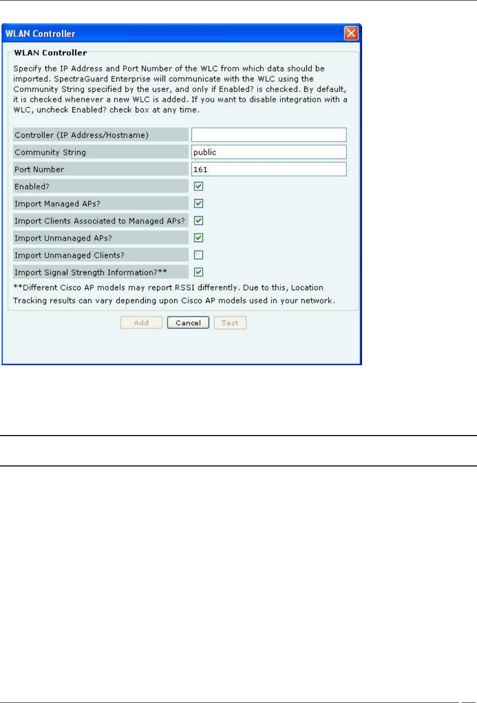
Adding a WLAN Controller
Under Wireless LAN Controllers, click <Add> to open WLAN Controller dialog where you can add WLC details.
Administration Tab
SpectraGuard® Enterprise User Guide
237
WLAN Controller Dialog
WLAN Controller contains the following fields:
Controller (IP Address/Hostname): Specifies the IP address or the hostname of the WLC with which the system
communicates.
Note: Configured WLCs will use the DNS names and DNS suffixes configured by the user in the Server
Initialization and Setup Wizard on the Config Shell.
Community String: Specifies the user defined community string using which the system communicates with
the WLC.
(Default: public)
Port Number: Specifies the port number of the WLC from which data is imported.
(Default: 161)
Enabled?: Indicates if the WLC is enabled to communicate with the system.
(Default: Enabled)
Import Managed APs?: Indicates if WLC managed APs managed are to be imported into the system.
(Default: Enabled)
Import Clients Associated to Managed APs?: Indicates if Clients associated to APs managed by a WLC are to
be imported into the system.
(Default: Enabled)
Import Unmanaged APs?: Indicates if APs not managed by a WLC are to be imported into the system.
(Default: Enabled)
Import Unmanaged Clients?: Indicates if Clients associated with APs not managed by a WLC are to be
imported into the system.
Administration Tab
SpectraGuard® Enterprise User Guide
238
(Default: Disabled)
Import Signal Strength Information?: Indicates if the signal strength of the managed devices is to be imported
into the system.
(Default: Enabled)
Note: Location Tracking results may vary depending on the Channel scan settings set on the WLC.
Click <Add> to add the details for a new WLC. Click <Test> to confirm the validity of IP Address/Hostname, SNMP
settings, and version compatibility of the newly added Lwapp Controller.
Editing a WLAN Controller
Double-click a row or click Edit to open an LWAPP Configuration dialog similar to the one shown above, to update
the WLC details. Click <Save> to save all settings.
Deleting a WLAN Controller
Select a row and click Delete to discard the details of an existing WLC. You can delete multiple WLC details using
click-and-drag or using the <Shift> + <Down Arrow> keys and then clicking Delete.
Note: From 6.2 release onwards, WLC will support the H-REAP mode along with the Local mode.
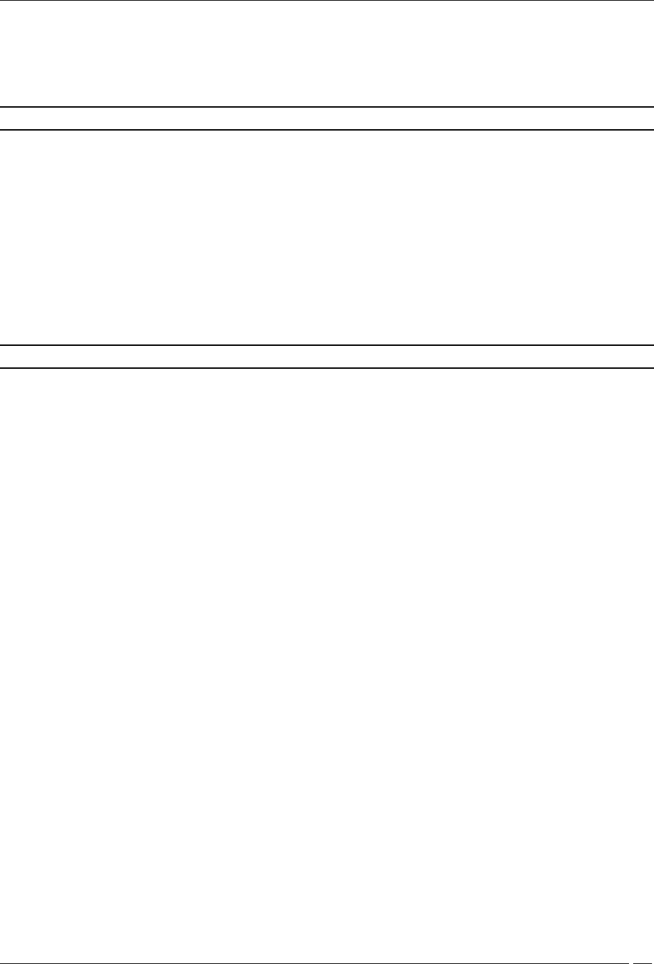
Integration with Cisco WLSE
Wireless LAN Solution Engine (WLSE) is a centralized, systems-level application that manages and controls an entire
Cisco AirTight WLAN infrastructure. WLSE eases Cisco’s WLAN deployments, enhances network security,
maximizes network availability, and reduces operating expenses.
Integration with Cisco WLSE allows the system to automatically classify WLSE managed APs and enables manual
switch port blocking to contain Rogue APs.
Administration Tab
SpectraGuard® Enterprise User Guide
239
Cisco WLSE
WLSE Integration Status: If WLSE integration is enabled, the system interacts with the configured WLSE server.
Else, WLSE integration services are shut off.
If you select WLSE Integration Enabled, you can configure the following WLSE Server Settings. The
system disables WLSE by default.
Current Status: Displays the Current Status of the WLSE server: Running or Stopped.
WLSE Server Settings: If a valid WLSE server is not specified, the system does not interface with the WLSE
Server.
WLSE Server IP Address/Hostname: Port: Specifies the IP address or the name and the port number of
the WLSE server
Username: Specifies the username for the WLSE server
Password: Specifies the password for the WLSE server
To test the WLSE server settings, click <Test WLSE Server Settings>. The settings used for this test are those that you
have specified. A dialog appears on completion of the test.
Note: The user created for the system should have XML API privileges on the WLSE server. You should
add the IP address of the server to the Access Control List of the WLSE server.
WLSE Operating Policies: Specifies policies to integrate the system with the WLSE server.
If you select Enable AP Classification integrated with WLSE, you can integrate the system’s AP Classification
and Intrusion Prevention policies with the WLSE sever such that:
WLSE-managed APs that are Potentially Authorized automatically move to the Authorized AP folder
All WLSE-managed APs automatically move to the Authorized AP folder
Administration Tab
SpectraGuard® Enterprise User Guide
240
Note: When you select the option All WLSE-managed APs automatically move to the Authorized AP folder
and connect a Rogue AP to the network, the port to which the AP is connected is not blocked. This is a limitation of
the WLSE API. In other words, the WLSE API provides only tracing functionality and not shutdown functionality.
Automatic Synchronization Settings: Specifies the interval at which the server should automatically
synchronize with the WLSE server.
Synchronization Interval (Days): Specifies the number of days: that is, the interval for which the server
synchronizes with the WLSE server.
(Minimum: 1 day; Maximum: 30 days; Default: 7 Days)
Synchronization Start Date and Time: Specifies the start date and time for the synchronization interval.
(Default: Current Date and Time)
Manual Synchronization: Click <Synchronize> to manually synchronize the server with the WLSE server.
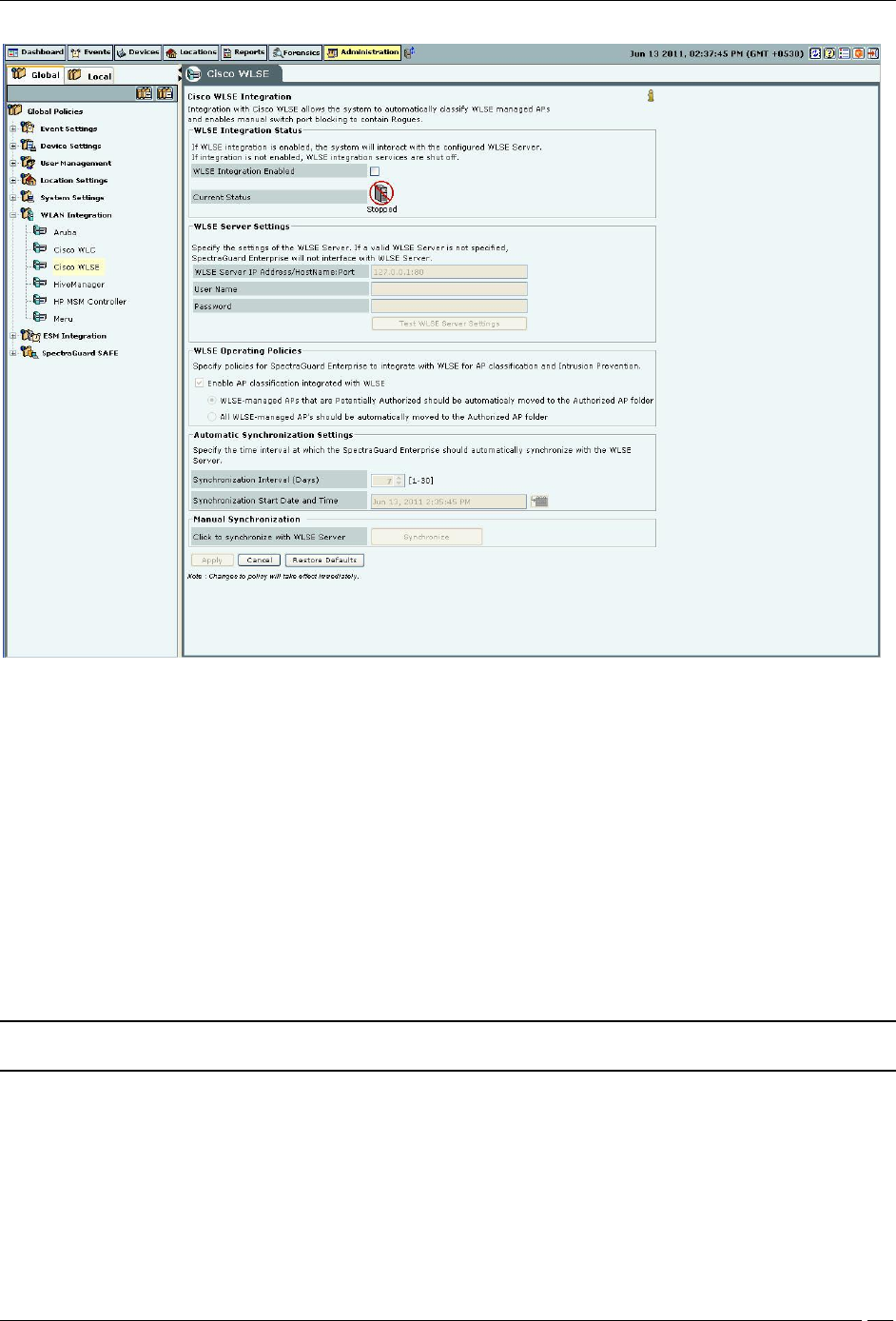
HiveManager
HiveManagers can synchronize devices and associations with the system. It reports both managed Hive APs with
their associations and devices visible in background scans.
HiveManager
WLAN Integrations displays the status of the HiveManager:
Client ID: Displays the Unique Integration Identifier of the HiveManager
Total APs: Displays the total number of import AP calls made by the HiveManager
Total Clients: Displays the total number of import Client calls made by the HiveManager
Total Associations: Displays the total number of AP-Client Association import calls made by the HiveManager
Last Sync Time: Displays the date and time of the last call made by the HiveManager
Note: Total gives the total number of HiveManagers.
Administration Tab
SpectraGuard® Enterprise User Guide
241
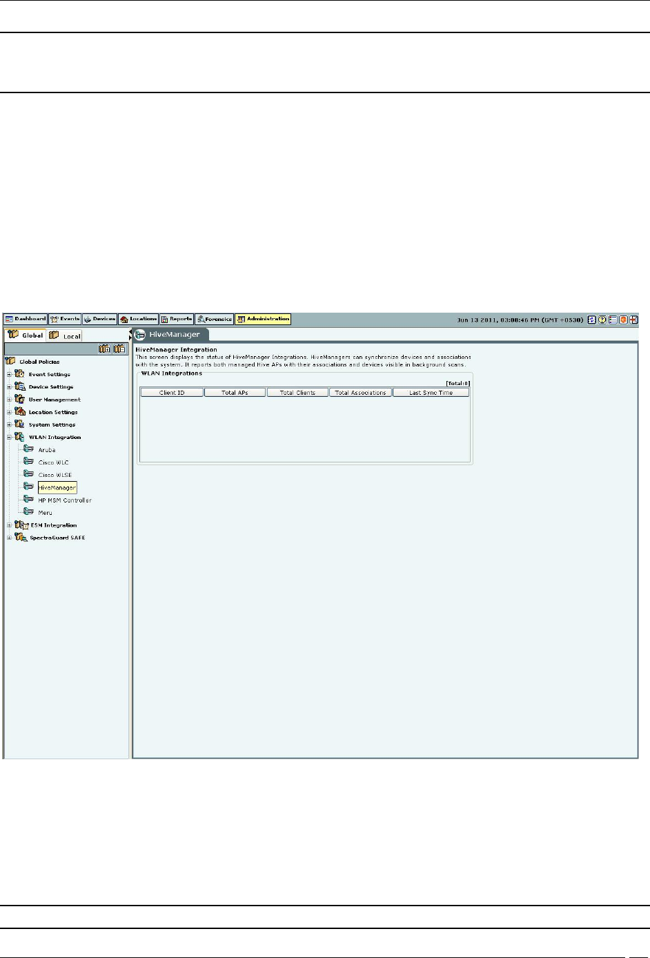
HP MSM Controller
The HP MSM Controller manages a collection of thin APs. The HP MSM architecture consists of MSM Controllers
and the APs that are managed by these controllers. Integration with HP MSM Controller allows the system to fetch
information about Synchronized APs. Using this information, the system automatically classifies these devices.
HP MSM Controller Integration
Important: The system supports HP MSM Controller version 5.4.2 or higher.
Integration Status: Enabling the MSM Controller integration allows the system to obtain data from the configured
controllers. Enabling / Disabling individual controllers is also possible.
Selecting Integration Enabled enables integration for all configured controllers.
Current Status: Displays Running if Integration is enabled. Displays Stopped if controller integration is switched
off. The Status field for each individual controller displays Error if
One of the configured and enabled MSM Controllers has a hostname which cannot be resolved
One of the configured and enabled MSM Controllers is not reachable
System server is stopped
Internal error (Contact Technical Support)
Under Automatic Synchronization Settings, select the System synchronization interval.
Synchronization Interval (Minutes): Specifies the interval after which the server synchronizes with the MSM
Controller.
(Minimum: 15 minutes; Maximum: 60 minutes; Default: 15 minutes)
Client Certificate Management: When the MSM Controller is configured to communicate with Client programs
using Secure HTTP and Client Authentication, a Client Certificate is uploaded into the MSM Controller’s Trusted CA
Administration Tab
SpectraGuard® Enterprise User Guide
242
Certificate Store. Click Download to download a pre-generated Client Certificate for the system. Following figure
displays the dialog box that appears on clicking the Download button.
Client Certificate Download Dialog
Click Save to download and save the Client Certificate to the appropriate directory.
Upload this Client Certificate into the MSM Controller’s Trusted CA Certificate Store using its management tool. The
system is now setup and ready to communicate with the MSM Controller.
Note: To customize the Client Certificate refer to the CLI commands: get msmcontroller cert, get msmcontroller
certreq, and set msmcontroller cert as described in Config Shell Commands in the Installation guide.
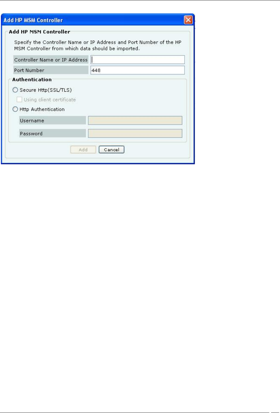
Adding an HP MSM Controller
Under MSM Controllers, click Add to configure an MSM Controller for integration. The following figure displays the
Add HP MSM Controller dialog.
Administration Tab
SpectraGuard® Enterprise User Guide
243
Add HP MSM Controller Dialog
HP MSM Controller contains the following fields:
Controller Name or IP Address: Specifies the Controller Name or IP address of the HP MSM Controller with
which the system communicates.
Port Number: Specifies the port number of the HP MSM Controller from which data is imported.
(Default: 448)
Authentication:
Secure Http (SSL/TLS): Select this option if the MSM Controller is configured to use HTTPS for authentication.
In addition, if the MSM Controller is setup to use Client Authentication, ensure that the System’s Client Certificate is
uploaded into the MSM Controller’s Trusted CA Certificate Store.
Http Authentication: If enabled, specifies whether the HP MSM Controller requires Http authentication
Username: Specifies the user name for HP MSM Controller authentication
Password: Specifies the password for HP MSM Controller authentication
Click the Add button to save the details for a new HP MSM Controller.
Editing an HP MSM Controller
Double-click a row or click Edit to open an HP MSM Controller dialog similar to the one shown above, to update the
HP MSM Controller details. Click Save to save all settings.
Deleting an HP MSM Controller
Select a row and click Delete to discard the details of an existing HP MSM Controller. You can delete multiple HP
MSM Controller details using click-and-drag or using the <Shift> + <Down Arrow> keys and then clicking Delete.
Enabling an HP MSM Controller
Select a row and click Enable to enable the selected HP MSM Controller. You can enable multiple HP MSM
Controller details using click-and-drag or using the <Shift> + <Down Arrow> keys and then clicking Enable.
Disabling an HP MSM Controller
Administration Tab
SpectraGuard® Enterprise User Guide
244
Select a row and click Disable to disable the selected HP MSM Controller. You can disable multiple HP MSM
Controller details using click-and-drag or using the <Shift> + <Down Arrow> keys and then clicking Disable.
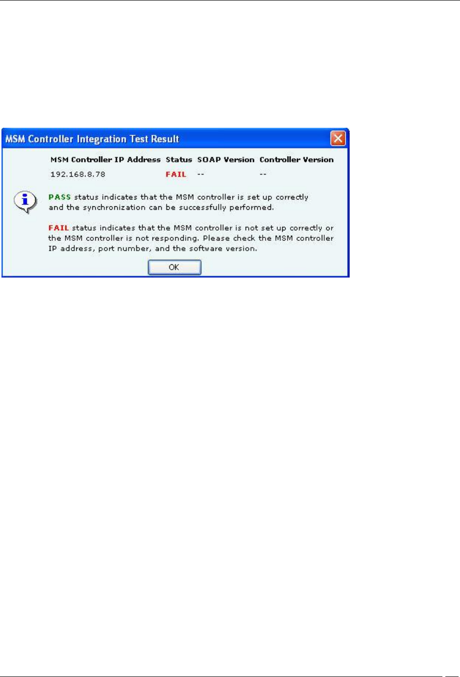
Checking configuration status of an HP MSM Controller
Select a MSM Controller row under MSM Controllers and click the Test button.
The System will return Pass status if the HP MSM Controller has been correctly configured.
The System will return Fail status if the HP MSM Controller has been not been correctly configured.
The following figure displays the message box displayed on evaluation of the HP MSM Controller setup.
MSM Controller Integration Test Result
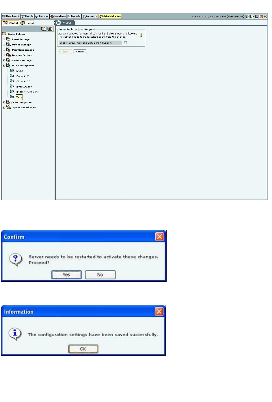
Meru
Meru Integration enables the system to use Virtual Cell and Virtual Port Architecture for reporting accurate AP
inventory. System also detects the physical APs to which the Clients are associated. This helps the user for accurate
location tracking and to protect against advanced threats.
Administration Tab
SpectraGuard® Enterprise User Guide
245
Meru
Select Enable Virtual Cell and Virtual Port Support check box to activate support for Meru Virtual Cell and Virtual
Port architecture. Click <Apply> a dialog appears to restart the server to activate the changes.
Server restart dialog
Click Yes. A confirmation dialog appears that the configuration settings have been saved successfully.
Confirmation dialog
ESM Integration
ArcSight ESM Server
Administration Tab
SpectraGuard® Enterprise User Guide
246
The Enterprise Security Management (ESM) Integration screen allows configuration of various ESM integrations that
collect, analyze, and display events.
The system integrates with ArcSight’s Enterprise Security Management (ESM) infrastructure by sending events to the
designated ArcSight server. The ArcSight server is configured to accept syslog messages having detailed event
information in ArcSight’s Common Event Format (CEF). The system needs the IP Address or the hostname and the
port on which the ArcSight server receives events.
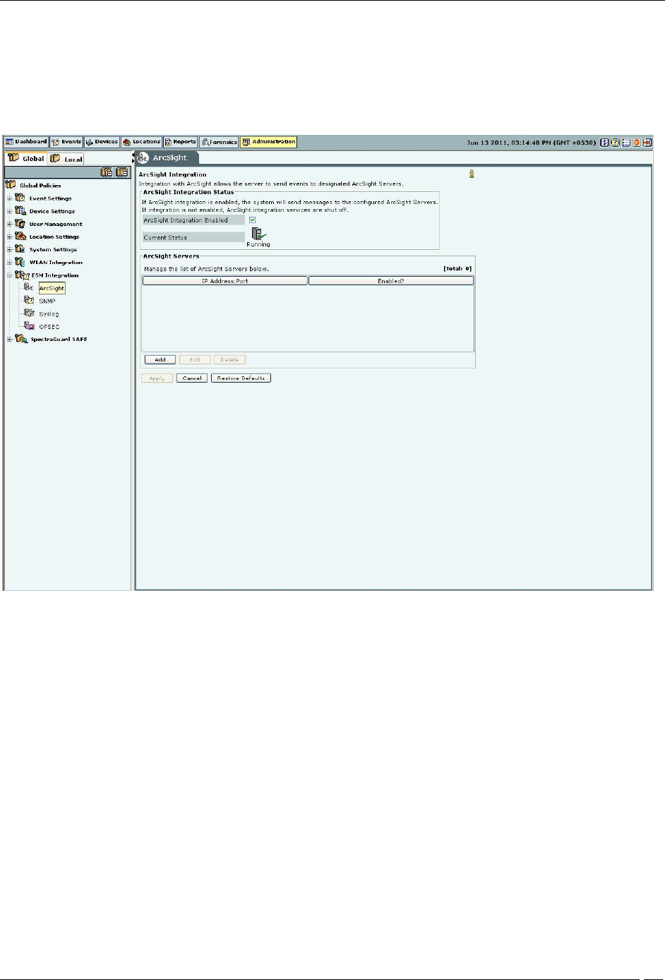
ArcSight ESM Server
ArcSight Integration Status: If ArcSight integration is enabled, the system sends messages to the configured
ArcSight servers. Otherwise, ArcSight integration services are shut off.
If you select ArcSight Integration Enabled, you can manage ArcSight servers. The system enables
ArcSight Integration by default.
Current Status: Displays the Current Status of the ArcSight Integration: Running or Stopped. An Error
status is shown in one of the following cases:
One of the configured and enabled ArcSight servers has a hostname, which cannot be resolved
System server is stopped
Internal error, in which case you need to contact Technical Support
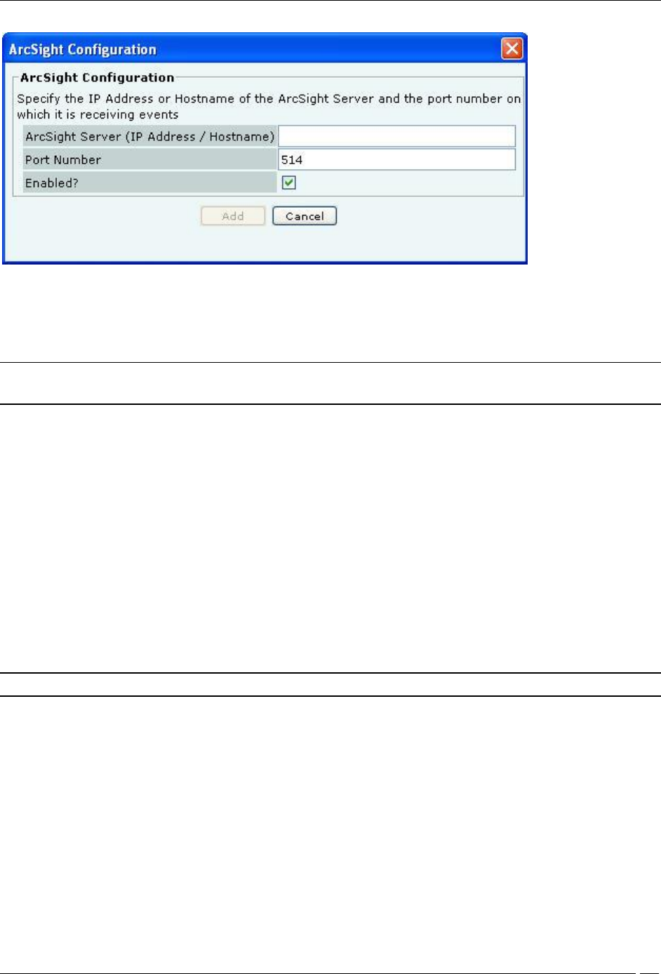
Adding an ArcSight Server
Under ArcSight Servers, click <Add>to open to ArcSight Configuration dialog where you can add ArcSight
server details.
Administration Tab
SpectraGuard® Enterprise User Guide
247
ArcSight Configuration Dialog
ArcSight Configuration dialog contains the following fields:
ArcSight Server (IP Address/Hostname): Specifies the IP Address or the hostname of the destination ArcSight
server to which the CEF formatted messages are sent.
Note: Configured ArcSight servers will use the DNS names and DNS suffixes configured by the user in the Server
Initialization and Setup Wizard on the Config Shell.
Port Number: Specifies the port number of the ArcSight server to which the system should send CEF messages.
Enabled?: If the checkbox is selected, the system sends CEF messages to the configured and enabled ArcSight
servers. The delivery of the CEF messages cannot be guaranteed due to use of UDP/unreliable transport.
(Default: Enabled)
Click Add to add the details for a new ArcSight server.
Editing an ArcSight Server
Double-click a row or click Edit to open ArcSight Configuration dialog similar to the one shown above. Click Save to
save all settings.
Deleting an ArcSight Server
Select a row and click Delete to discard the configuration of the selected ArcSight server. You can delete multiple
ArcSight server details using click-and-drag or using the <Shift> + <Down Arrow> keys and then clicking Delete.
Note: Total gives the total number of ArcSight servers configured to receive events from the system.
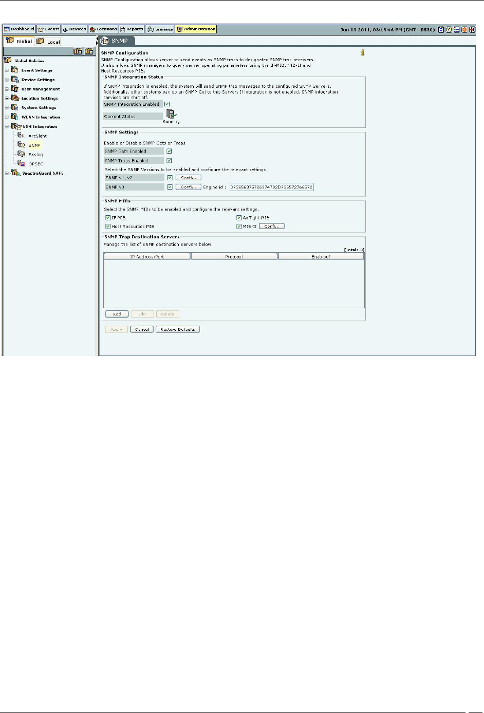
SNMP
The SNMP dialog enables the system to send events as SNMP traps to designated SNMP trap receivers. It also allows
SNMP managers to query server operating parameters using IF-MIB, MIB-II, and Host Resources MIB.
Administration Tab
SpectraGuard® Enterprise User Guide
248
SNMP
SNMP Integration Status: If SNMP integration is enabled, the system sends SNMP traps to the configured
SNMP servers. Other systems can do an SNMP Get to this server. Otherwise, SNMP integration services are shut off.
If you select SNMP Integration Enabled, you can edit and manage SNMP server details. The system enables
SNMP by default.
Current Status: Displays the Current Status of the SNMP server: Running or Stopped. An Error status is shown
in one of the following cases:
System server is stopped
Internal error, in which case you need to contact Technical Support
Under SNMP Settings, configure SNMP Gets or Traps.
SNMP Gets Enabled: Allows SNMP managers to query server-operating parameters enlisted in IF-MIB, MIB-II,
and Host Resources MIB. You can block queries related to all of the above listed MIBs by de-selecting the checkbox.
SNMP Traps Enabled: Allows SNMP traps to be sent to configured SNMP servers.
Additionally, select the SNMP versions to be enabled and configure the relevant settings. The SNMP agent residing
on the server uses the SNMP version parameters to deliver traps to the SNMP Trap receivers.
SNMP v1, v2: If selected, traps are sent to all Trap receivers accepting traps using SNMP v1, v2 protocol. You
can change the Community String for the SNMP agent. All SNMP v1, v2 Trap receivers configured, should use this
community string to receive traps.
(Default: public)
SNMP v3: If selected, traps are sent to all Trap receivers accepting traps using SNMP v3 protocol. You can
change the Username and Password for the SNMP agent. All SNMP v3 Trap receivers configured, should use these
parameters to receive traps. The Engine ID field is un-editable.
(Default Username: admin; Default Password: password)
Under SNMP MIBs, you can choose to query by enabling or disabling the following SNMP MIBs individually.
Administration Tab
SpectraGuard® Enterprise User Guide
249
IF MIB
Host Resources MIB
AirTight-MIB: If selected, the system enables the external SNMP Trap receivers to receive traps
MIB-II: If selected, configure the System Contact, System Name, and System Location.
(Default System Name: Wi-Fi Security Sever)
Note: IF MIB, Host Resources MIB, an MIB II are standard MIBs that you can download from the Internet. For
AirTight-MIB, contact AirTight Technical Support.
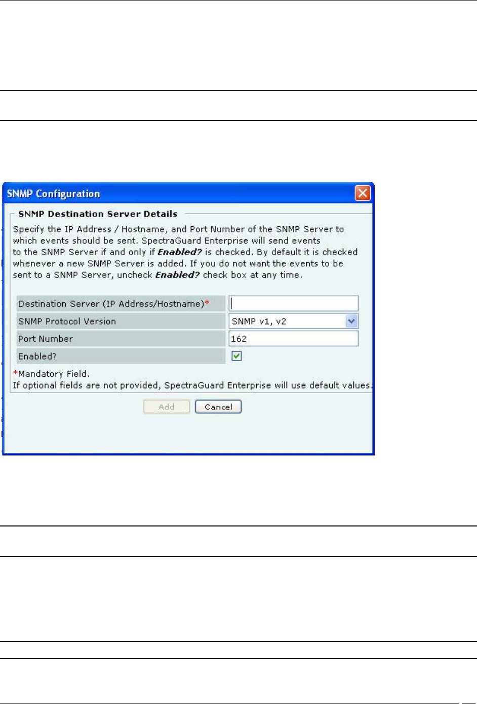
Adding a SNMP Trap Destination Server
Under SNMP Trap Destination Servers, click Add to open SNMP Configuration dialog where you can add
SNMP server details.
Add SNMP Configuration Dialog
Trap Destination Details contains the following fields:
Destination Server (IP Address/Hostname): Specifies the IP address or the hostname of the SNMP server to
which events should be sent.
Note: Configured SNMP servers will use the DNS names and DNS suffixes configured by the user in the Server
Initialization and Setup Wizard on the Config Shell.
SNMP Protocol Version: Specifies the SNMP protocol version for the SNMP agent.
(Default: SNMP v1, v2)
Port Number: Specifies the port number on the receiving system to which the SNMP trap is sent.
(Default: 162)
Enabled?: Specifies if the SNMP server is enabled to receive SNMP traps.
(Default: Enabled)
Note: You must specify a different port number if another application uses the default port.
Click Add to add the details for a new SNMP server.
Administration Tab
SpectraGuard® Enterprise User Guide
250
Editing a SNMP Trap Destination Server
Double-click a row or click Edit to open SNMP Configuration dialog similar to the one shown above to update the
SNMP server details. Click Save to save all settings.
Deleting an SNMP Trap Destination Server
Select a row and click Delete to discard the details of an existing SNMP server.
Syslog
Integrating with Syslog servers
The Syslog screen allows the server to send events to designated Syslog receivers.
Syslog
Syslog Integration Status: If Syslog integration is enabled, the system sends messages to the configured Syslog
servers. Otherwise, Syslog integration services are shut off.
If you select Syslog Integration Enabled, you can manage Syslog servers. The system enables Syslog by default.
Current Status: Displays the Current Status of the Syslog server: Running or Stopped. An Error status is shown
in one of the following cases:
One of the configured and enabled Syslog servers has a hostname, which cannot be resolved
System server is stopped
Internal error, in which case you need to contact Technical Support
Adding a Syslog Server
Administration Tab
SpectraGuard® Enterprise User Guide
251
Under Manage Syslog Severs, click <Add> to open Syslog Configuration dialog where you can add Syslog
server details.
Syslog Configuration Dialog
Syslog Configuration contains the following fields:
Syslog Server (IP Address/Hostname): Specifies the IP address or the hostname of the Syslog server to which
events should be sent.
Note: Configured Syslog servers will use the DNS names and DNS suffixes configured by the user in the Server
Initialization and Setup Wizard on the Config Shell.
Port Number: Specifies the port number of the Syslog server to which the system sends events.
(Default: 514)
Message Format: Specifies the format in which the event is sent, which is Intrusion Detection Message Exchange
Format (IDMEF) or Plain text.
(Default: Plain text)
Note: If you upgrade a server pre-6.2 to 6.6, all previously configured Syslog servers would send events in Plain
text Message Format by default. You can select the IDMEF format by editing the Syslog server settings.
Enabled?: Specifies if the events are to be sent to this Syslog server.
(Default: Enabled)
Click Add to add the details for a new Syslog server.
Editing a Syslog Server
Double-click a row or select a row and click Edit to open Syslog Configuration dialog similar to the one shown above.
Click Save to save all settings.
Deleting a Syslog Server
Select a row and click Delete to discard the details of an existing Syslog server.
Administration Tab
SpectraGuard® Enterprise User Guide
252
OPSEC
Operations Security (OPSEC) is an analytic process used to deny an adversary information – generally unclassified –
concerning our intentions and capabilities by identifying, controlling, and protecting indicators associated with our
planning processes or operations. OPSEC does not replace other security disciplines – it supplements them.
OPSEC
Integration with OPSEC enables the system to send events to the specified OPSEC server.
OPSEC Integration Status: If OPSEC integration is enabled, the system sends events to the configured OPSEC
servers. Otherwise, OPSEC integration services are shut off.
If you select OPSEC Integration Enabled, you can configure OPSEC server settings. The system disables
OPSEC by default.
Current Status: Displays the Current Status of the OPSEC server: Running or Stopped. An Error status is
shown in one of the following cases:
System server is stopped
OPSEC configuration is either incomplete or incorrect or if the OPSEC server is stopped
Internal error, in which case you need to contact Technical Support
Under OPSEC Server Settings specify the OPSEC server details.
Server Name: Specifies the name of the OPSEC server
Server IP: Specifies the IP Address of the OPSEC server
Authentication Port: Specifies the OPSEC server authentication port used for communication with the
system
Specify the authentication type you can select one of the following types of authentication:
Clear

Administration Tab
SpectraGuard® Enterprise User Guide
253
SSL
SSL OPSEC
SSL Clear
SSL Clear OPSEC
FWN
Auth OPSEC
SSL CA
SSL CA Comp
SSL CA RC4
SSL CA RC4 Comp
Asymmetric SSL CA
Asymmetric SSL CA Comp
Asymmetric SSL CA RC4
Asymmetric SSL CA RC4 Comp
SSLA Clear
Under SIC Settings, you need to specify the following settings for the Simple Instructional Computer (SIC) for
all the authentication types except ‘Clear’:
Server SIC Name: Specifies the server name of the SIC
Client SIC Name: Specifies the Client name of the SIC
Under CA Settings, if you have selected an authentication type that has a CA in it, select Create new digital
certificate, then, you need to configure the following parameters for the Certifying Authority (CA).
IP/Hostname: Specifies the IP address or the hostname of the CA
Object Name: Specifies the object name of the CA
Password: Specifies the one time password needed to acquire the certificate
Under Symmetric Key Based Settings, if you have selected an authentication type that does not have a CA in it,
select Create New Secret Key, then, you need to create a new secret key.
SpectraGuard SAFE
The SpectraGuard SAFE screen enables you to setup and manage groups for wireless Clients running SAFE.
Group Management
Group Management allows the user to manage SAFE policy groups. SAFE groups can be created manually. The
system can also be configured to create SAFE groups automatically from the users’ domain and logged in group as
reported by SAFE.
Each group can have a SAFE policy attached to it. The SAFE policies are created using a SAFE Client. The policy
configuration is then imported in the system.
The system gives the administrators the option to categorize the SpectraGuard SAFE Clients into groups
automatically. Automatic movement of SpectraGuard SAFE Client is based on the SAFE user’s domain and group
name information. Manual assignment of SAFE Clients to a group overrides any automatic assignment.
You cannot edit the default group.
Administration Tab
SpectraGuard® Enterprise User Guide
254
SAFE Group Management
Note: For Automatically created groups, “SAFE Reported Group” column displays information about the domain name and
group name (OU Hierarchy) reported by SAFE Client as “<Domain Name>/<Group Name (OU Hierarchy)>”. For Manually
created groups, it displays “ - -“.
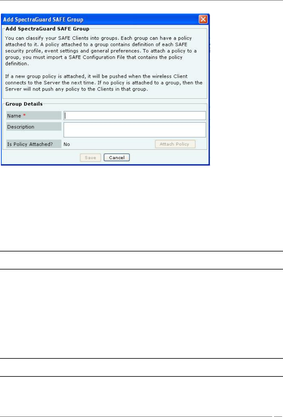
Adding a SAFE Group Manually
Click Add Group to open Add SpectraGuard SAFE Group dialog where you can add the details for various SAFE
groups.
Administration Tab
SpectraGuard® Enterprise User Guide
255
Add SAFE Group Dialog
Under Group Details, specify the following:
Name: Specify a group name for the newly created group.
Description: Specify a brief description for the group.
Is Policy Attached?: Indicates if a policy is attached to the newly defined group.
Click Attach Policy to navigate to the path where the SAFE Configuration file is saved. Attach the policy.
Configuration File: Displays the entire path or location of the SAFE Configuration file.
Click Save to save the details for the new group.
Note: Duplicate group names are allowed for manually defined groups. The group name of a SAFE reported group
and manually created group can be the same.
Attaching SAFE Policy to existing SAFE Group
Use the following steps to attach a policy to an existing SAFE group:
1 On the SpectraGuard SAFE Group Management screen, select the SAFE group to which you want to attach a
policy.
2 On the Edit SpectraGuard SAFE Group dialog that appears, click Attach Policy.
3 On the Confirm dialog that appears, click Yes.
4 On the Select SAFE Configuration File dialog, specify the path of the SAFE configuration file (.XML format)
and click Open.
5 Click Save to attach the policy to the SAFE group.
Note: It is not mandatory to export the IP Address and Shared Key information from the SAFE Client as it already
has this information when it connects to the server.
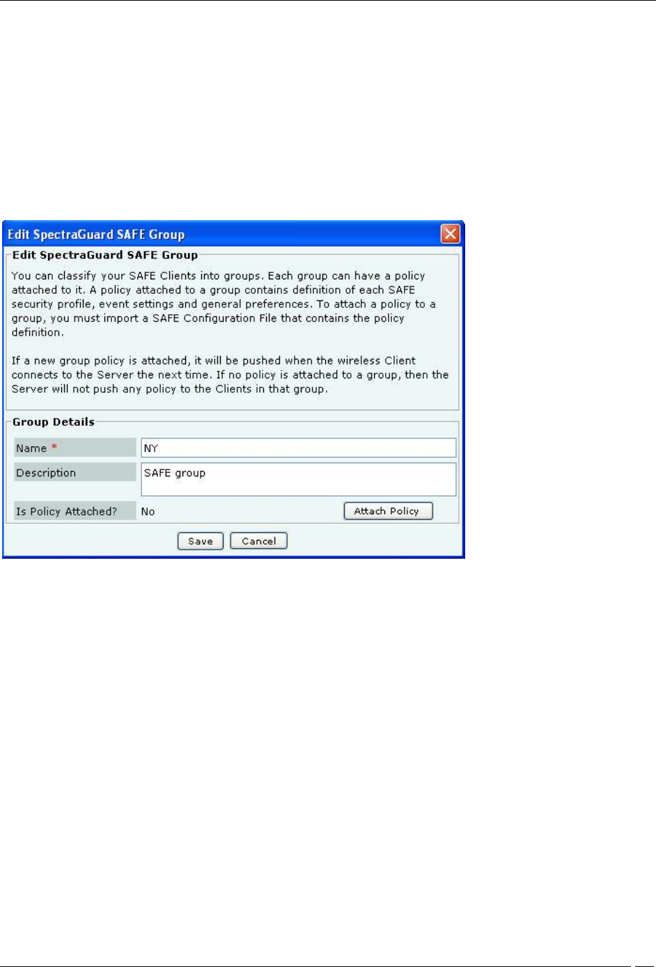
Editing a SAFE Group
Administration Tab
SpectraGuard® Enterprise User Guide
256
Select a group from the List of Groups and click Edit Group to open Edit SpectraGuard SAFE Group dialog where
you can edit the details of an existing SAFE Group. Additionally, in this dialog you can do the following:
Click the hyperlink View Policy to view the attached policy.
Click Overwrite Policy to overwrite the existing policy attached to the SAFE group with the policy
contained in a SAFE Configuration file.
Click Detach Policy to detach the existing policy attached to the SAFE group. If no policy is attached to a
group, the server does not push any policy to the Clients in that group. The Clients retain their previous
policy. When you do not attach a policy or you detach a policy from a SAFE group, the system does not
send the Activity Parameter information such as Keep-alive Interval, Keep-alive Timeout, and
Synchronization Interval to the Clients belonging to that SAFE group.
Edit a SAFE Group
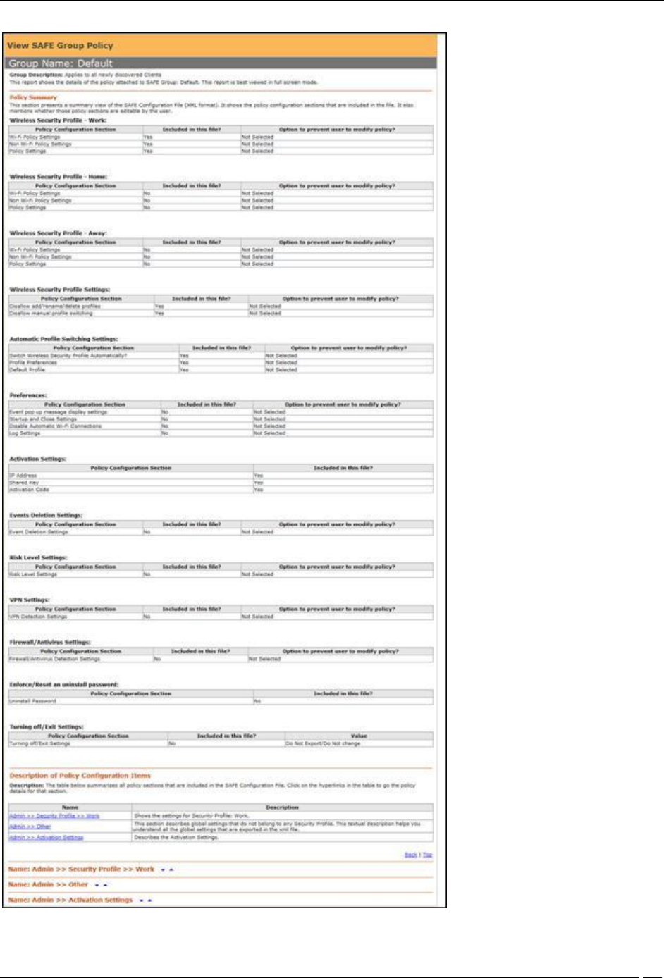
Viewing a SAFE Group Policy
On the SpectraGuard SAFE Group Management screen, for the selected SAFE group, click the hyperlink View
Policy. Alternatively, on the Edit SpectraGuard SAFE Group dialog, click the hyperlink View Policy. A report
showing the details of the policy group attached to the selected SAFE group appears.
Administration Tab
SpectraGuard® Enterprise User Guide
257
View a SAFE Group Policy
Administration Tab
SpectraGuard® Enterprise User Guide
258
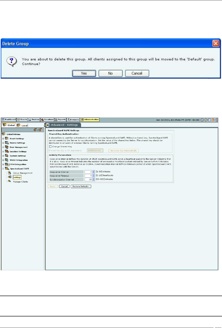
Deleting a SAFE Group
Select a group from the List of Groups and click Delete Group. The Delete Group message appears. Click Yes to
confirm deletion. After deleting the group all the Clients in that group are assigned to 'Default' group.
Delete a SAFE Group
Settings
A shared key is used for authentication of Clients running SAFE. SAFE cannot connect to the server for
synchronization without a shared key. This shared key should be distributed to all the users of wireless Clients
running SAFE.
SAFE Settings
Under Shared Key Authentication, do one of the following:
Select Change Shared Key to change the existing shared key.
Note: You need to be very careful about changing the Shared Key if it has already been circulated to existing SAFE
Clients. This is because, if you change the Shared Key, existing SAFE users will not be able to connect to the
server unless they re-activate their SAFE Clients using the new Shared Key.
Administration Tab
SpectraGuard® Enterprise User Guide
259
Click Generate Key Automatically to enable the system to automatically generate a shared key of up to 10
alphanumeric characters using which SAFE Clients can connect with the system.
Under Activity Parameters, specify the following:
Keep-alive Interval: Defines the duration at which SAFE sends a heartbeat to the server indicating that it is
active.
(Minimum: 1 minute; Maximum: 30 minutes; Default: 2 minutes)
Keep-alive Timeout: Indicates the number of consecutive heartbeat packets missed by the server before it
declares that SAFE instance as inactive.
(Minimum: 2 heartbeats; Maximum: 10 heartbeats; Default: 5 heartbeats)
Synchronization Interval: Defines the minimum period at which SAFE synchronizes with the server.
(Minimum: 30 minutes; Maximum: 300 minutes; Default: 60 minutes)
Manage Clients
This screen displays details of the SAFE Clients registered with the server.
Manage SAFE Clients
This screen shows the following information about SAFE Clients:
SAFE Status Icon: Identifies the SAFE status – Active or Not Active.
SAFE Risk Level Icon: Identifies the SAFE risk level – High, Medium, or Low.
Report Availability for SAFE Client: Indicates one of the following Report available, Report not available, or
Report Scheduled.
Name: Specifies the First name and Last name or hostname of the Client.
Wireless MAC: Specifies the first detected wireless MAC address of the Client in case of multiple wireless
interfaces.
Wired MAC: Specifies the first detected wired MAC address of the Client in case of multiple wired interfaces.
Administration Tab
SpectraGuard® Enterprise User Guide
260
Version: Specifies the build and version number of the software loaded in the Client.
Group: Specifies the group name as defined through Group Management. The asterisk before a group name
indicates that the group has been manually changed for the client, from a SAFE reported group to manually created
group.
SAFE Reported Group: Specifies the SAFE reported group to which the Client belongs. , “SAFE Reported
Group” column displays information about the domain name and group name (OU Hierarchy) reported by SAFE
Client as “<Domain Name>/<Group Name (OU Hierarchy)>”.
Last Synch: Specifies the time when the SAFE Client last synchronized with the system.
Activation: Specifies the date and time when the SAFE Client was activated.
Last Available Report: Specifies the time when a report was last generated for the selected SAFE Client.
Configure Display Columns: Clicking on the Column Visibility icon opens a window showing the columns
available for display and their current selection and display order. You can check/uncheck the checkbox before the
column name to select/deselect it from SAFE Client List display. You can change the display order of a column by
selecting the column name and moving it up/down with Up/Down buttons. Save the display settings by clicking
<Save> button.
Max Allowed: Specifies the maximum number of SAFE Clients that can be connected to the system. This
number depends on the number of users permitted by your SGE license.
SAFE Client List – Display Columns Screen
Note: The Console displays either a SAFE Client that has only a wired interface or a SAFE Client not yet
categorized on a white row on the Manage SAFE Clients screen.
Double-clicking a SAFE Client row displays the SAFE Details dialog.
Administration Tab
SpectraGuard® Enterprise User Guide
261
SAFE Client Details Dialog
Note: The servers with version 5.7, 5.9, 6.0, 6.1, and 6.2 are compatible with SAFE versions 2.5 and 2.7.
Right-clicking a SAFE Client row displays the context sensitive menu.
SAFE Client Context Sensitive Menu
Items in the SAFE Client Context Sensitive Menu
The SAFE Client context-sensitive menu includes the following items.
SAFE Details: Enables you to view details of the SAFE Client as shown in the Client Details dialog.
Delete: Allows you to delete a SAFE Client. It displays a Confirm dialog that enables you to delete a selected
SAFE Client. Click <Yes> to delete the SAFE Client.
Fetch Report: Available for a SAFE Client which is Active, this option if selected, displays a progress bar and
then fetches a fresh report from the SAFE Client.
Schedule Report: Available for a SAFE Client which is Inactive, this option enables you to schedule a report for
the selected SAFE Client. A fresh report is generated for the Client when it becomes Active.
View available report: Available for a SAFE Client for which a report is fetched earlier, this option displays a
progress bar and then a report that enables you to view various reports generated earlier for the selected SAFE Client.
Each time the system generates a SAFE report, it updates the Last Available Report column on the Manage SAFE
Clients screen.
Administration Tab
SpectraGuard® Enterprise User Guide
262
SAFE Client Report
Change SAFE Group: Enables you to change the group of the selected Client to any group except the group currently
associated with the selected Client. After the Clients group changes, the new policy is applied to the SAFE Client.
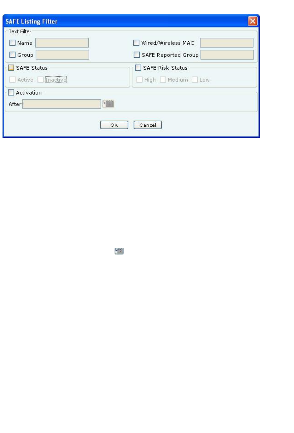
Filtering in SAFE
To focus your attention to a subset of SAFE Client List based on a filtering criteria (such as SAFE Status, SAFE Risk
Status, and so on) system provides you with the capability to filter SAFE Client List. Use the following steps to filter
SAFE Client List:
1 Click the Filter icon to open the SAFE Listing Filter dialog.
Administration Tab
SpectraGuard® Enterprise User Guide
263
SAFE Listing Filter
2 Under Text Filter, select one or more of the following check boxes and enter the appropriate values manually for
searching data related to it:
Name
Wired/Wireless MAC
Group
SAFE Reported Group
3 Select the SAFE Status check box, select one or more of the following check boxes:
Active
Inactive
4 Select the SAFE Risk Status check box, select one or more of the following check boxes:
High
Medium
Low
5 Select the Activation check box, click the icon to specify the date and time of the activation of the SAFE
Client and then click OK. The search displays the SAFE Client list, which were first detected by the system after the
date as specified above
6 Select the Group check box, select the Group Name from the drop down box for searching data related to it.
7 To save and apply the SAFE Client List filtering criteria, click OK. When the filter is applied it is denoted by
Filter On on the Console, if no filter is applied it is denoted by Filter Off on the Console.
Local Policies
Local Policies
About Local Policies
Local Policies are those that you can customize for a particular location. When you create a new location, by default,
all the policies for this new location are always the same as its parent location. In other words, this newly created
location inherits policies from its parent. You can change these inherited policies. Specifically a user with
administrative rights can configure these policies for a location.
Click the Local tab in the Administration screen to view the policies groups under this tab.
The Local tab consists of two trees:
Location tree on the top
Administration tree at the bottom
Administration Tab
SpectraGuard® Enterprise User Guide
264
Recommended: Do not use distinct policies for two locations that represent geographically close-by areas. This is
because if two locations are very close, it is possible that sensors from both these locations see a device, thereby
affecting the accuracy of location tagging for the device.
Policy and Policy Groups
The system clubs policies in Local Policies with related functionality into groups called Policy Groups. Examples of
policy groups and policies within them are as shown below.
Example 1
Operating Policies (Policy Group)
AP Auto-classification(Policy1)
Client Auto-classification (Policy 2)
Intrusion Prevention (Policy 3)
Example 2
Event Settings (Policy Group)
Configuration (Policy 1)
Email Notification (Policy 2)
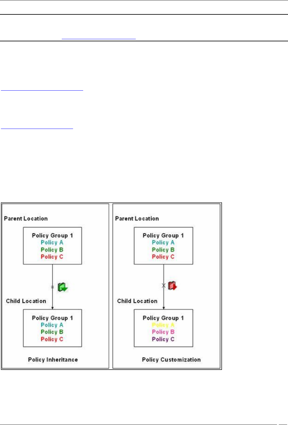
Customizing v/s Inheriting Policies
By default, a location inherits policies from its parent location. You can break the inheritance and customize the
policies at a location.
You can customize or inherit policies only at the policy group level. Customize or inherit of individual policies is not
allowed at the individual policy level within the policy group. By customizing or inheriting a policy in a policy group,
the policy group gets customized or inherited.
Policy Inheritance v/s Customization
Customizing Policies
Use the following steps to customize policies in a policy group for a location that inherits policies from its parent:
Administration Tab
SpectraGuard® Enterprise User Guide
265
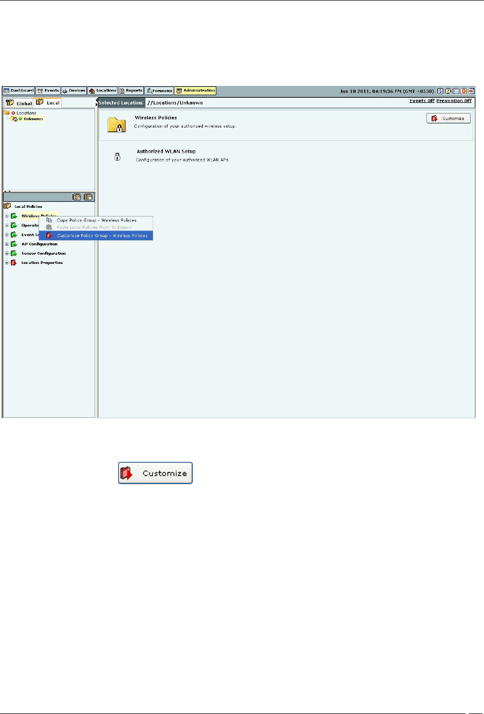
1. Select the Local tab.
2. Select a location in the Location tree for which you want to customize the policies.
3. Select a policy group from the Administration tree.
4. Right-click either the selected location or the selected policy group. A context sensitive menu appears. Click
Customize Policy Group – ‘<Policy Group Name>’.
Customizing a Policy Group
5. Alternatively, click on the right side of the policy group pane.
6. Alternatively click the hyperlink Customize in the sentence ‘Click Customize to re-define this policy at this
location.’ on the individual policy page. By customizing the individual policy, the entire policy group is
customized.
You can now custom define the individual policies within the policy node.
Inheriting Policies: (Re)establishing Inheritance
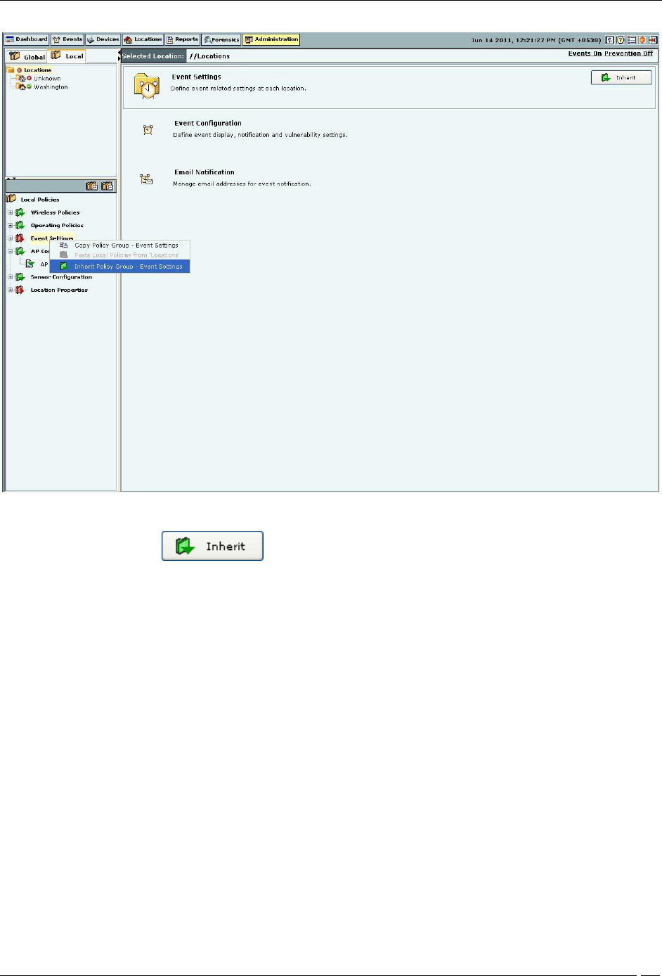
Use the following steps to inherit policies in a policy group for a location which has customized policies:
1. Select the Local tab.
2. Select a location in the Location tree for which you want to inherit policies from its parent.
3. Select a policy group from the Administration tree.
4. Right-click either the selected location or the selected policy group. A context sensitive menu appears. Click
Inherit Policy Group – ‘<Policy Group Name>’.
Administration Tab
SpectraGuard® Enterprise User Guide
266
Inheriting Policies for a Policy Group
5. Alternatively, click on the right side of the policy group pane.
6. Alternatively click the hyperlink Inherit in the sentence ‘Click Inherit to inherit this policy from its parent
location.’ on the individual policy page. By inheriting the individual policy, the entire policy group is
inherited from its parent location.
This re-establishes the inheritance link for the selected policy group. The policy group loses any existing
customization for the selected location and starts using the parent policies instead. Once policies are inherited, action
items like checkboxes, buttons, and so on are de-activated in the policy pane. You will see the policies in a Read-only
mode.
Template Based Policies
In the system, some policies are made up of one or more templates. In a large setup with several locations, the
administrator would like to create templates on a single location and reuse these templates, if other locations in the
sub-tree need to have similar templates to define their policies.
Applying a Template
A user can create templates at locations to which access has been granted. You can then select one or more such
templates to be applied at a particular location. Thus, when you apply one or more templates to a location, you
define the policy for that location.
Template Availability at Sub-locations
Administration Tab
SpectraGuard® Enterprise User Guide
267
When you create a new template at a location, it is available for viewing and applying to all the locations in its sub-
tree. Templates can only be modified and deleted at the location at which they are created.
Copying and Pasting of Local Policies
In a large setup with several locations, the administrator would like to custom define policies for just one location. If
other locations need to have policies similar to the ones already defined, you can Copy the policies from the first
location and Paste them to the other locations.
Copy allows you to copy one or all policy groups customized for a particular location to another location. If all the
policy groups for a location are inherited from its parent, you cannot copy policies from that location.
Paste allows you to paste the policies to a policy group on any location. By pasting a policy group on a location
inheriting that policy group, the inheritance is broken.
Copying and Pasting all Local Policies
Use the following steps to copy and paste all Local policies:
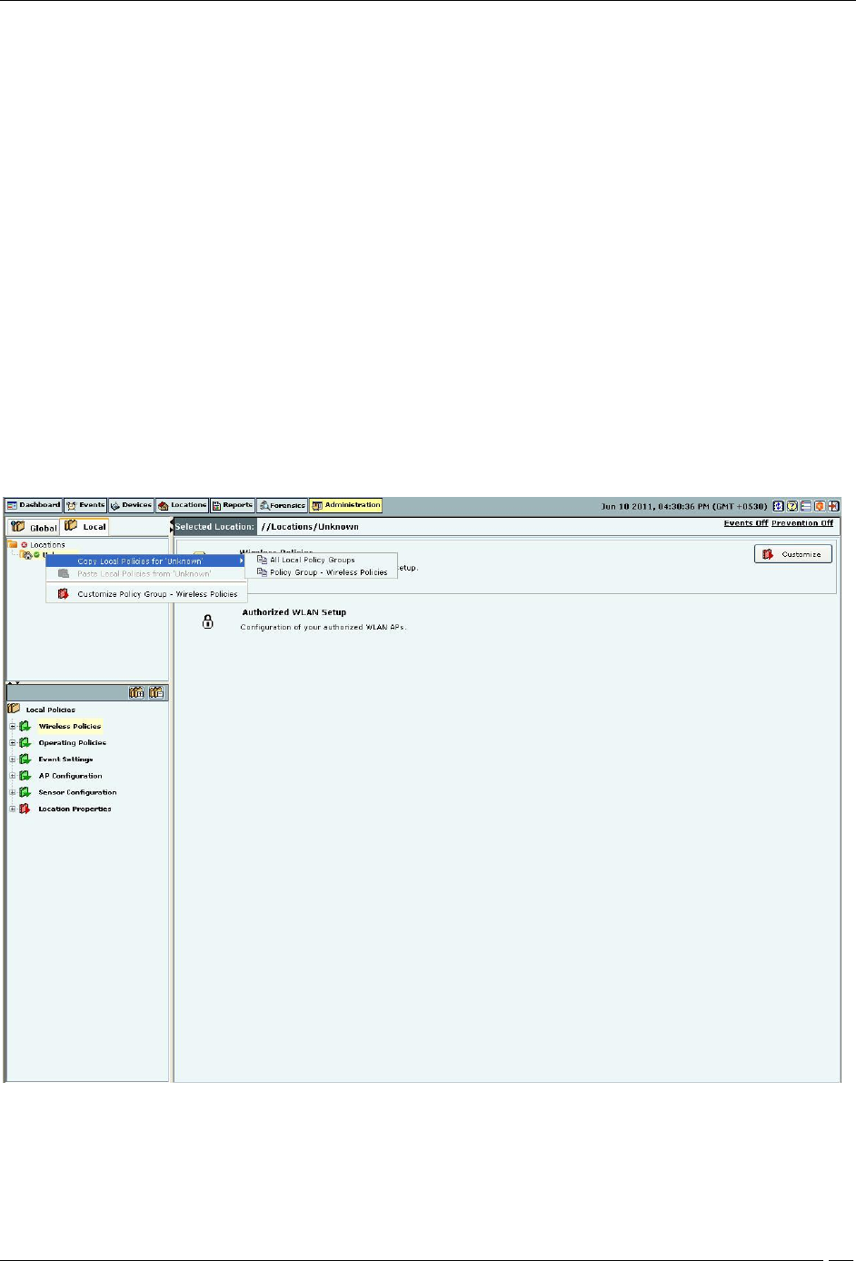
1. Right-click a location from the Location tree which you choose to copy (source location).
2. From the resultant context-sensitive menu, select Copy Local Policies for ‘<Location Name>’.
3. Select All Local Policy Groups or Policy Group-‘<Policy Group Name>’. The Policy Group-‘<Policy Group
Name>’ option is available only if a policy group node is selected in the Administration tree.
Copying all Local Policies
4. Right-click a location to which you want to paste the copied policies.
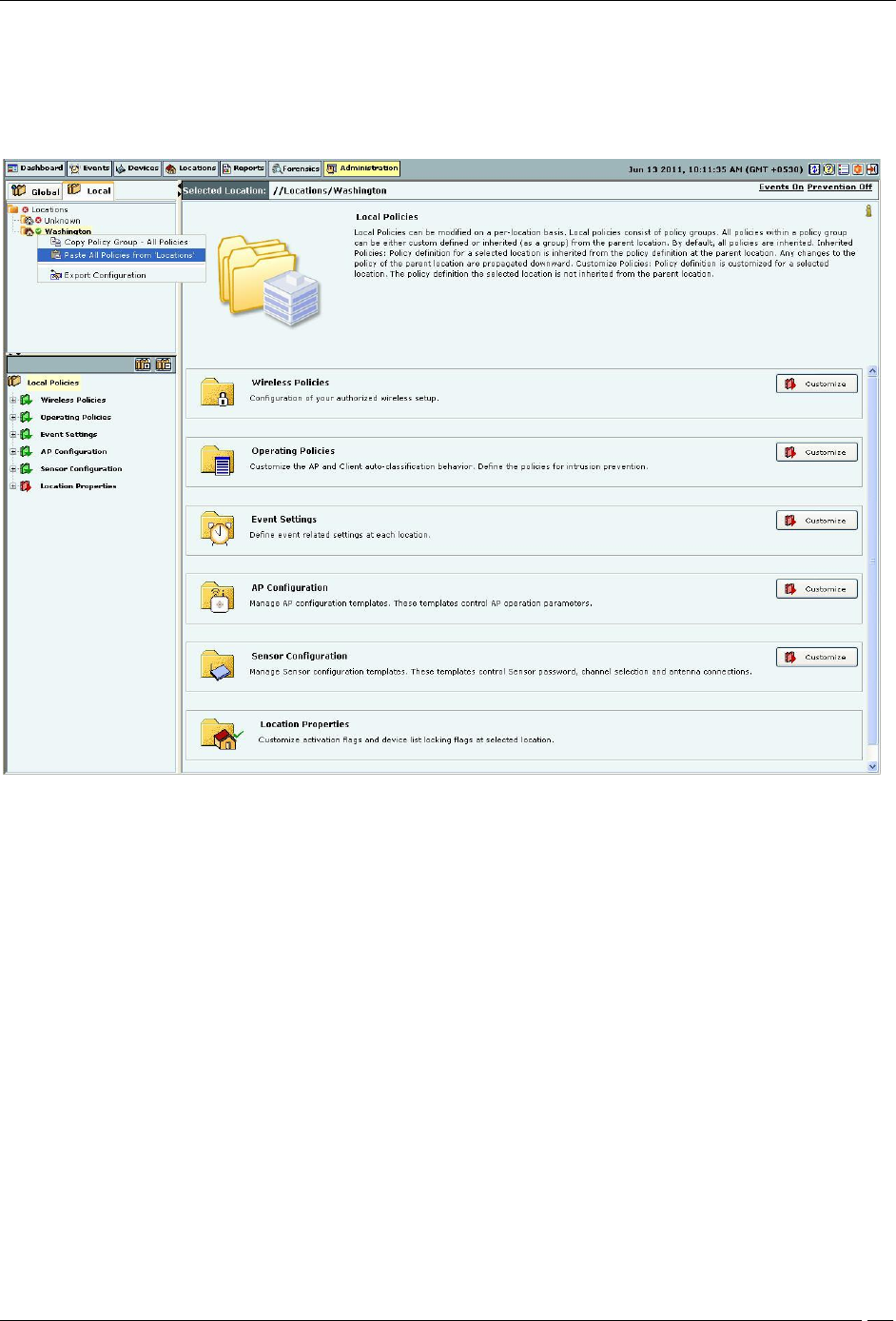
Administration Tab
SpectraGuard® Enterprise User Guide
268
5. From the resultant context-sensitive menu, select Paste All Policies from ‘<Location Name>’ or Paste
‘<Policy Group Name>’ from ‘<Location Name>’. The Paste All Policies from ‘<Location Name>’ is
displayed if all the policies were copied during the copy operation. The Paste ‘<Policy Group Name>’ from
‘<Location Name>’ option is displayed if only a policy group is copied during the copy operation.
Pasting all Local Policies
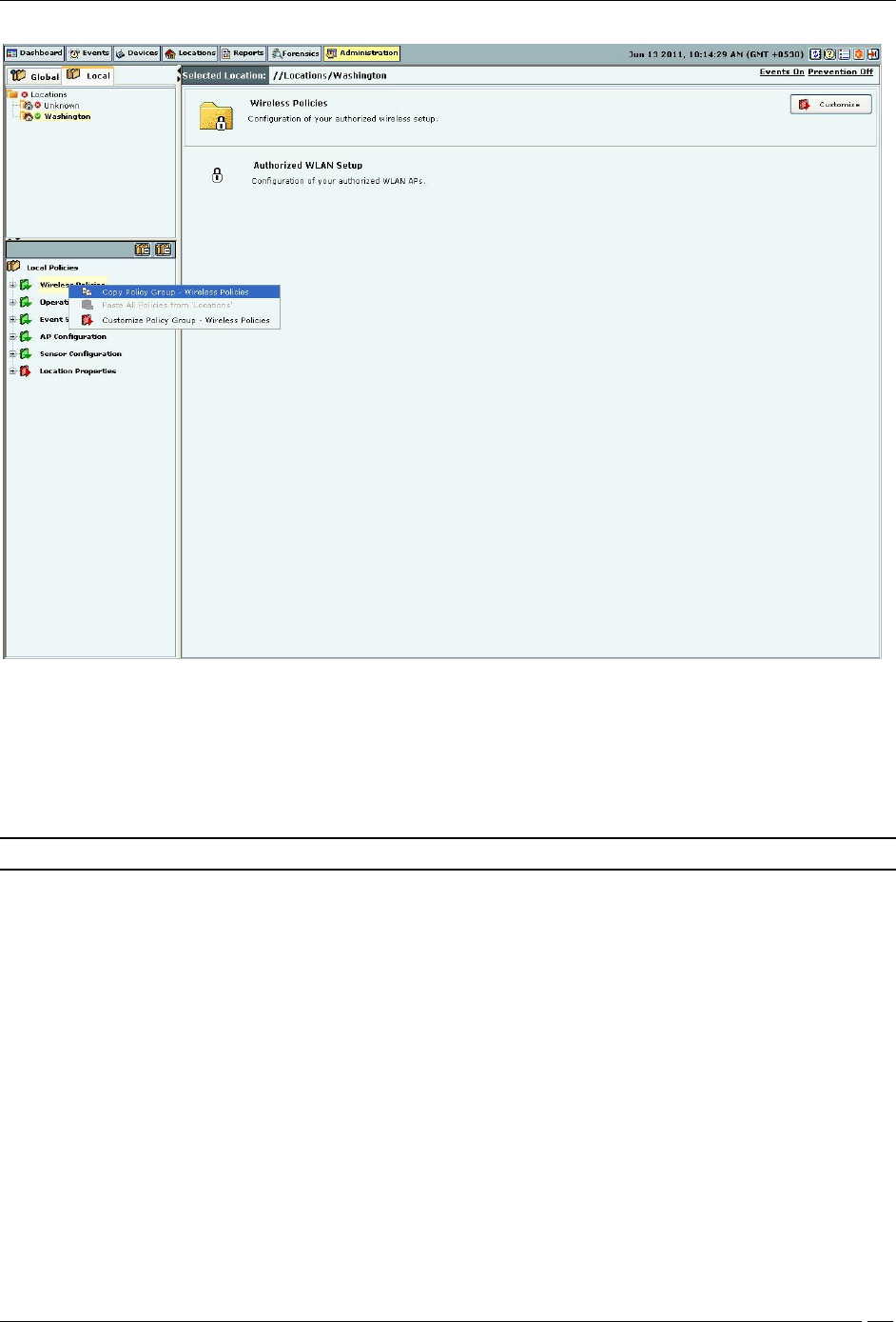
Copying and Pasting a Local Policy Group
Use the following steps to copy and paste a Local policy group:
1. Right-click a location from the Location tree.
2. Right-click a policy group from the Administration tree which you choose to copy.
3. From the resultant context-sensitive menu, select Copy Policy Group-‘<Policy Group Name>’.
Administration Tab
SpectraGuard® Enterprise User Guide
269
Copying a Local Policy Group
4. Right-click a location to which you want to paste the copied policies.
5. From the resultant context-sensitive menu, select Paste ‘<Policy Group>’ from ‘<Location Name>’.
Note: The copy operation is not allowed if no local policy group is custom defined or customized on that location.
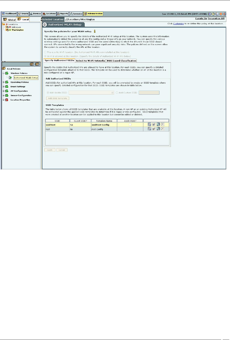
Wireless Policies-Authorized WLAN Setup
Select the Wireless Policies screen to specify the Authorized Wi-Fi policies for a particular location.
Authorized WLAN Setup
The system uses the details of the Authorized Wi-Fi setup at a particular location to detect the presence of Mis-
configured or Rogue APs in your network. You can specify the details of authorized SSIDs and a list of networks to
which Authorized APs can connect.
Administration Tab
SpectraGuard® Enterprise User Guide
270
Authorized WLAN Setup
Select one of the following to characterize a particular location:
This is a No Wi-Fi location: If no Authorized Wi-Fi APs are installed at this location. If you configure a location as
a no Wi-Fi location, the Specify Authorized SSID section is grayed out.
Wi-Fi is allowed at this location: To specify the details of the Authorized Wi-Fi APs in this location.
Specify Authorized SSIDs
Under this tab, specify the Authorized SSIDs at this location. For each SSID, you can specify the detailed
configuration. This per SSID configuration is called an SSID template.
Creating a Configuration Template for an Authorized 802.11 SSID
Add Authorized SSIDs allows you to create an SSID template in one of the following ways:
Add Visible SSID: To create an SSID template from a list of visible SSIDs. The visible SSID list is built using the
data received from sensors.
Add Custom SSID: To create a template using a user-defined SSID.
Click Add SSID template to create a new SSID template. The Template for an Authorized 802.11 SSID dialog
appears where you can select multiple items in some fields.