Molex CVS Dabendorf 128-01 Bluetooth Handsfree Car Kit User Manual Manual
Novero Dabendorf GmbH Bluetooth Handsfree Car Kit Manual
Manual
Operating Manual
128 8001 1.01
US
English
EGO TALK
Funkwerk Dabendorf reserves the right to modifi cations in the course of technological progress and deviations from the
delivery scope! All rights reserved! Reproduction, in whole or in part, is only permitted with the prior written consent of
Funkwerk Dabendorf GmbH!

List of contents
1 LIST OF CONTENTS 3
2 LIST OF ILLUSTRATIONS 5
3 INTRODUCTION / FOREWORD 6
4 SAFETY NOTES 7
5 SCOPE OF DELIVERY / PACKAGE CONTENT 8
6 INSTALLATION GUIDE 9
6.1 Determination of required confi guration 9
6.1.1 Vehicle 9
6.1.2 Telephone 9
6.1.3 Muting (Radio Muting) 9
6.1.4 Upgrading existing Funkwerk hands-free installations to EGO TALK 9
6.1.5 Add-on speakers / car audio telephone connection 10
6.1.6 Car audio line-in 10
6.2 Installation locations 10
6.2.1 Checking cable lengths 10
6.2.2 Selection of the point of installation for the electronics box 10
6.2.3 Selection of the point of installation for the microphone 11
6.2.4 Selection of the point of installation for the control console 12
6.3 Installation 12
6.3.1 Mounting the electronics box 12
6.3.2 Mounting the microphone 13
6.3.3 Mounting the control console 13
6.4 Connection scheme 14
6.5 Installation of the ISO connecting cable 16
6.5.1 Checking the mute inputs 16
6.5.2 Checking the installation 18
1
2 | 3

6.5.3 Additional external speakers 18
6.6 Connecting the components to the electronics box 19
6.7 Operational test 21
7 OPERATING MANUAL 22
7.1 Features 22
7.1.1 Overview of features 22
7.2 Symbols 22
7.3 Getting started 24
7.3.1 About Bluetooth© technology 24
7.3.2 On / Off function 25
7.3.3 Coupling 25
7.3.4 Automatic connection 25
7.4 Calling 26
7.4.1 Incoming call 26
7.4.2 Outgoing call 26
7.5 Audio Player 26
7.5.1 Coupling 26
7.5.2 Play / Pause 27
7.5.3 Stop 27
7.5.4 Skip features 27
7.6 Volume 27
8 SERVICE 28
9 SPARE PARTS AND ACCESSORIES 30
10 TECHNICAL SPECIFICATIONS 32
11 CERTIFICATION 32
12 CONFORMITY STATEMENT 33
13 HOTLINE 35
EGO TALK

2
4 | 5
List of illustrations
Fig. 01 Scope of delivery 8
Fig. 02 Signal orientation of Bluetooth® antenna 10
Fig. 03 Installation location for electronics box 11
Fig. 04 Installation location for microphone 11
Fig. 05 Installation dimensions of electronics box 12
Fig. 06 Connecting the Mini-ISO-connector 15
Fig. 07 Installation procedure 16
Fig. 08 Type-dependent pin allocation 17
Fig. 09 Plug wiring scheme 17
Fig. 10 Connection system 17
Fig. 11 a/b Changing power supply wiring 18
Fig. 12 Connecting external loudspeakers 19
Fig. 13 Connecting the electronics box 20

Introduction/Foreword
Congratulations on your new EGO!
EGO TALK is the intelligent entry-level solution for telephone use in your car: simple to operate, elegant and compact
– with Bluetooth and audio enjoyment, too. EGO TALK has an integrated MP3 playback function for your mobile phone,
your iPod™ or any other MP3 Player. Enjoy your favourite tracks on your car’s audio speakers, in superb stereo sound.
The installation of your EGO TALK in your car requires specialized knowledge and skills. We therefore recommend that
the installation be performed by a qualifi ed professional.
Before installation in your car, please make sure that your mobile phone is fully compatible with EGO TALK. If you are
uncertain, please consult your dealer or a qualifi ed workshop. Our service team will also be happy to help you with any
information you may require. Further information on compatibility between EGO TALK and various mobile phones can be
found on our website.
3
EGO TALK

Safety notes
1. Incorrect installation – Incorrect installation may lead to damage to the units and/or your car! Specialized knowledge
and skills are required for installing the system. We strongly recommend that the system be installed by a qualifi ed
professional.
2. Risk of injury – Unsuitable installation locations may become a source of injury in an accident situation, or may inhibit the
correct functioning of essential safety equipment. Please carefully read the notes in the „Installation“ chapter carefully!
3. Risk of injury/material damage – the removal of vehicle lining with sharp or pointed objects may lead to injuries or
material damage.
4. Road safety risk – Diverted attention can lead to dangerous situations in traffi c. Even when using hands-free phone
systems, your complete attention must be paid to the current traffi c conditions. It is always advisable to avoid
phone calls while driving in diffi cult traffi c situations!
5. Damage to airbags – An incorrect installation location may cause damage to, or inhibit the correct function of, your
airbags. Do not install the components within the deployment area of the airbags!
6. Insulation damage – Damaged insulation can lead to equipment and wiring damage. The cables and leads may not be
under tension when installed. Install the cables and leads in such a way as to avoid pinching or abrasion.
7. Polarity and shorting damage – Cables connected with reversed polarity, or in such a way as to produce a short
circuit, can lead to serious damage to your equipment. Before commencing installation, make sure that the car
battery is disconnected.
8. Damage to essential vehicle components – Essential vehicle components or wiring can be damaged when drilling
mounting holes or screwing in self-threading screws. Please make sure there is always suffi cient space behind the
screw holes and drilled holes!
9. Interference with on-board electronics – Despite the extreme protection against interference, incorrect installation
can lead to interference with the vehicle electronic systems. Please read the vehicle manufacturer’s notes to this
effect!
10. Appropriate use – This equipment is intended solely for use with mobile telephones in motor vehicles.
11. Damage caused by inappropriate replacement parts – Inappropriate spare or replacement parts may lead to
malfunctions. Please use only the approved parts listed in the section „Spares parts and accessories“!
12. Road safety risk – For your own safety, never initiate the coupling procedure while your vehicle is in motion!
4
6 | 7
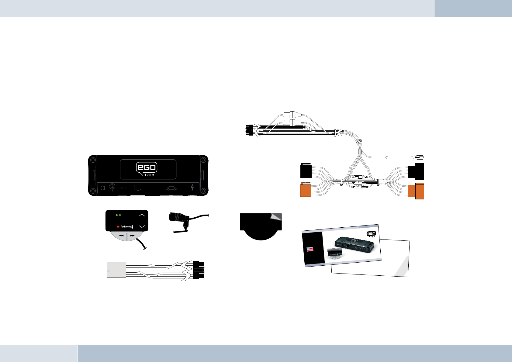
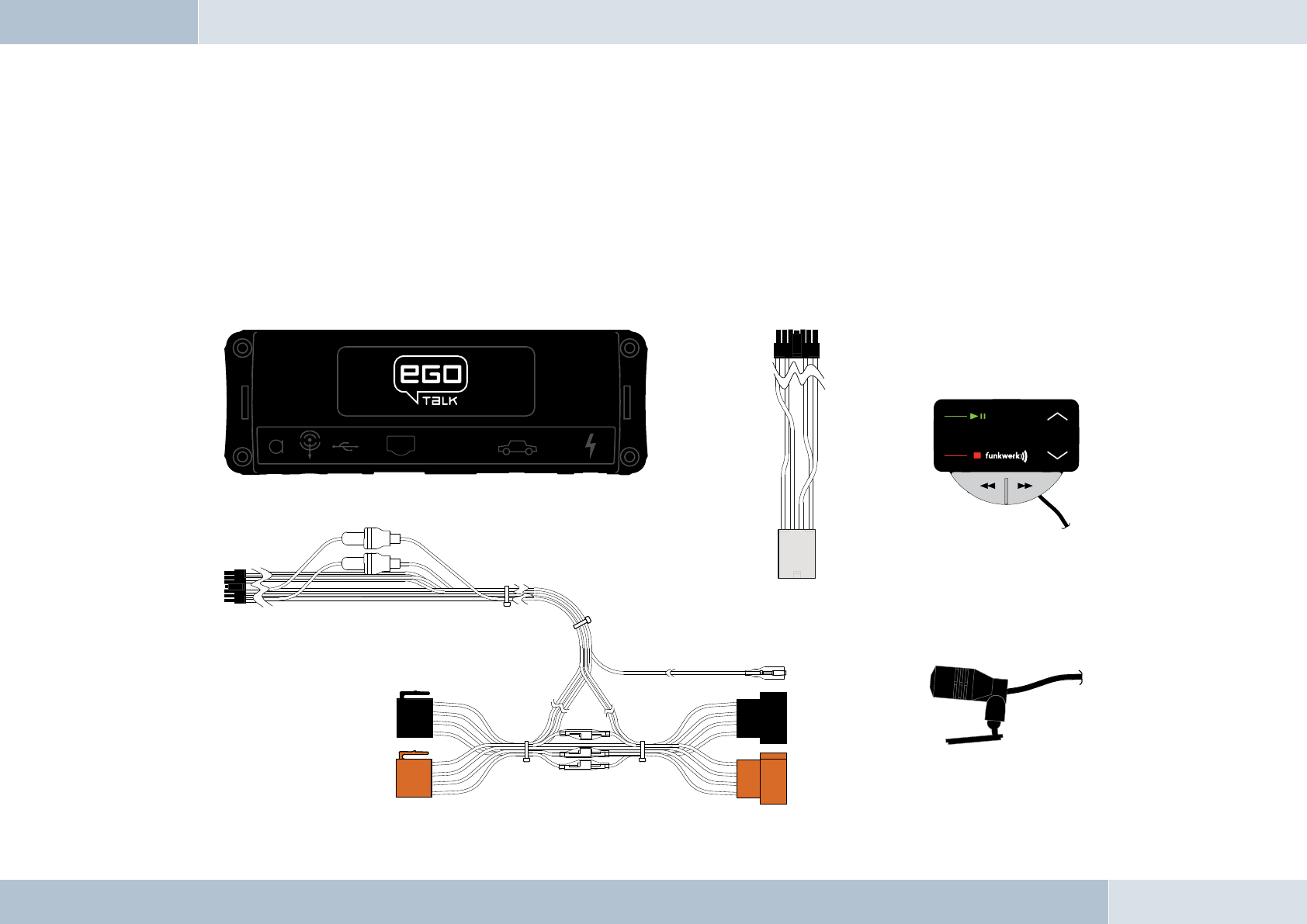
Scope of delivery / package content
[1] Electronics box
[2] Control console
[3] Microphone
[4] ISO-cable for connection to the car electrical system
[5] Adapter cable
[6] Self-adhesive pad
[7] Quick guide
[8] Safety manual
PLEASE MAKE SURE THE CONTENT OF THE PACKAGE is complete. If any parts are missing, please don‘t hesitate to
contact our service hotline team: +49 (0) 3377 - 316 233, Mon.–Thurs 7.00 a.m.–5.00 p.m., Fri. 7.00 a.m.–4.00 p.m.
5
q
[1]
[2] [3]
Safety Instructions
1. Improper installation – Improper installation may cause damages to the unit or to the v
abilities. We therefore strongly recommend to have the installation one by a professional.
2. Personal
injury – Inappropriate places for the installation may cause personal injuries in
“Installation”!
3. Personal
injury / Material damage – When you remove coverings or armature parts, sha
D
on’t submit the connecting cables to pressure.
4. Negative
eects on road safety – Ta l kin g whi l t d i
[7]
[8]
QUICK
GUIDE
EGO TALK
128 8011 1 01
[4]
Fig. 01:
Scope of Delivery
[5]
[6]
EGO TALK

Installation guide
6.1 Determination of required confi guration
Before installation of your EGO TALK, please note which features and connection options are provided by your car audio
system. It is advantageous when your audio has the following: a muting function, phone input and line-in. You can fi nd out
which of these input options your audio system has in the documentation provided.
6.1.1 Vehicle
The hands-free system may only be installed in vehicles with a negative grounded, 12 V electrical system. If no car audio is
installed, an add-on speaker will be required. For the installation of the optional charging cradle, you will require a model-
specifi c mounting that may be purchased from a specialist dealer
6.1.2 Telephone
A Bluetooth®-compatible telephone must be available for use with this system. You can fi nd a list of supported Bluetooth®
telephones online at www.fwd-online.de.
6.1.3 Muting (radio muting)
The muting function (Radio Muting) ensures that the audio sound is turned off during telephone calls. The system
supports the muting function. Your car`s audio documentation will show whether your car audio has a mute option. If your
car audio is not equipped with a muting option, you can install the optionally available Stereo Mute Box to facilitate speaker
muting.
6.1.4 Upgrading existing Funkwerk hands-free installations to EGO TALK
The adapter cable is the ideal and simple solution for customers who already own a Funkwerk hands-free system (e.g.
Audio 2000, 3000, Audio blue, Audio com, Audio compact) and would like to upgrade to EGO TALK. The adapter cable
connects the ISO cable of your existing Funkwerk hands-free system to the EGO TALK.
NOTE! This simple upgrade is only possible for installations without a Stereo Mute Box. When installing your EGO TALK with
a Stereo Mute Box, the ISO cable from the Stereo Mute Box is to be used for the connection to the car’s electrical system.
6
8 | 9
q
6.1.5 Add-on speakers / Car audio telephone connection
The car’s loudspeakers are transferred to the system is by means of switch contacts. These are designed for a peak power
handling of 35 W (Sinus). Loudspeaker power handling exceeding 35 W leads to premature wear on the switching contacts.
For higher outputs, use the telephone connection of the car audio or a 5 W / 4-Ohm satellite speaker. This port is only
designed for voice reproduction.
6.1.6 Car audio line-in input
A car audio with a line-in input option is required for music reproduction in stereo. As an alternative to line-in, the car
audio may have a mini-ISO port (block connector C), a 0.14 in jack socket or a RCA input socket. An appropriate adapter
lead is required for the connection between the EGO TALK line-out and the line-in version of your audio system. If your
car audio system has no line-in option, you can employ the optionally available Stereo Mute Box for stereo reproduction in
combination with your car’s front speakers.
6.2 Installation locations
RISK OF INJURY! Unsuitable installation locations may become a source of injury in an accident (or emergency braking)
situation, or may inhibit the correct functioning of essential safety equipment.
6.2.1 Checking cable lengths
Before you’ve securely installed the components, check that
the installation locations have been selected in such a way
that the cable length is suffi cient to connect the individual
components.
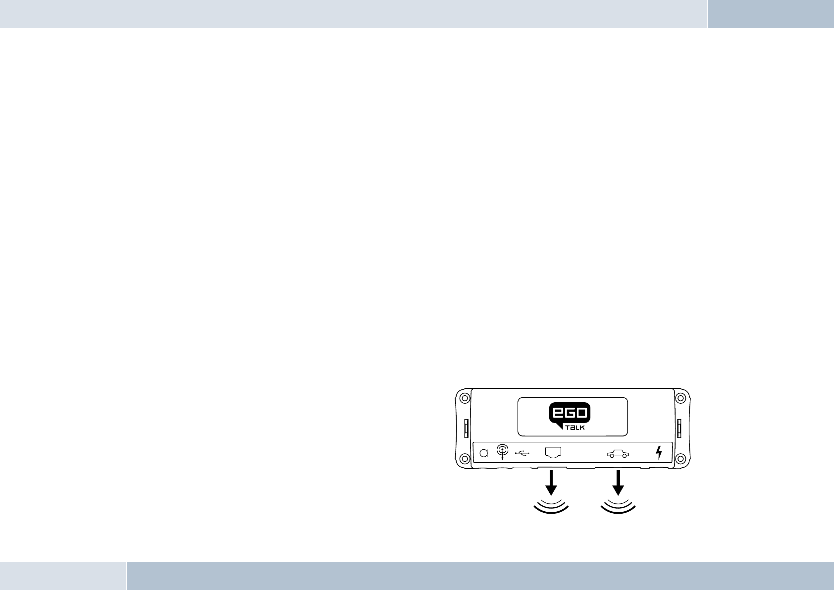
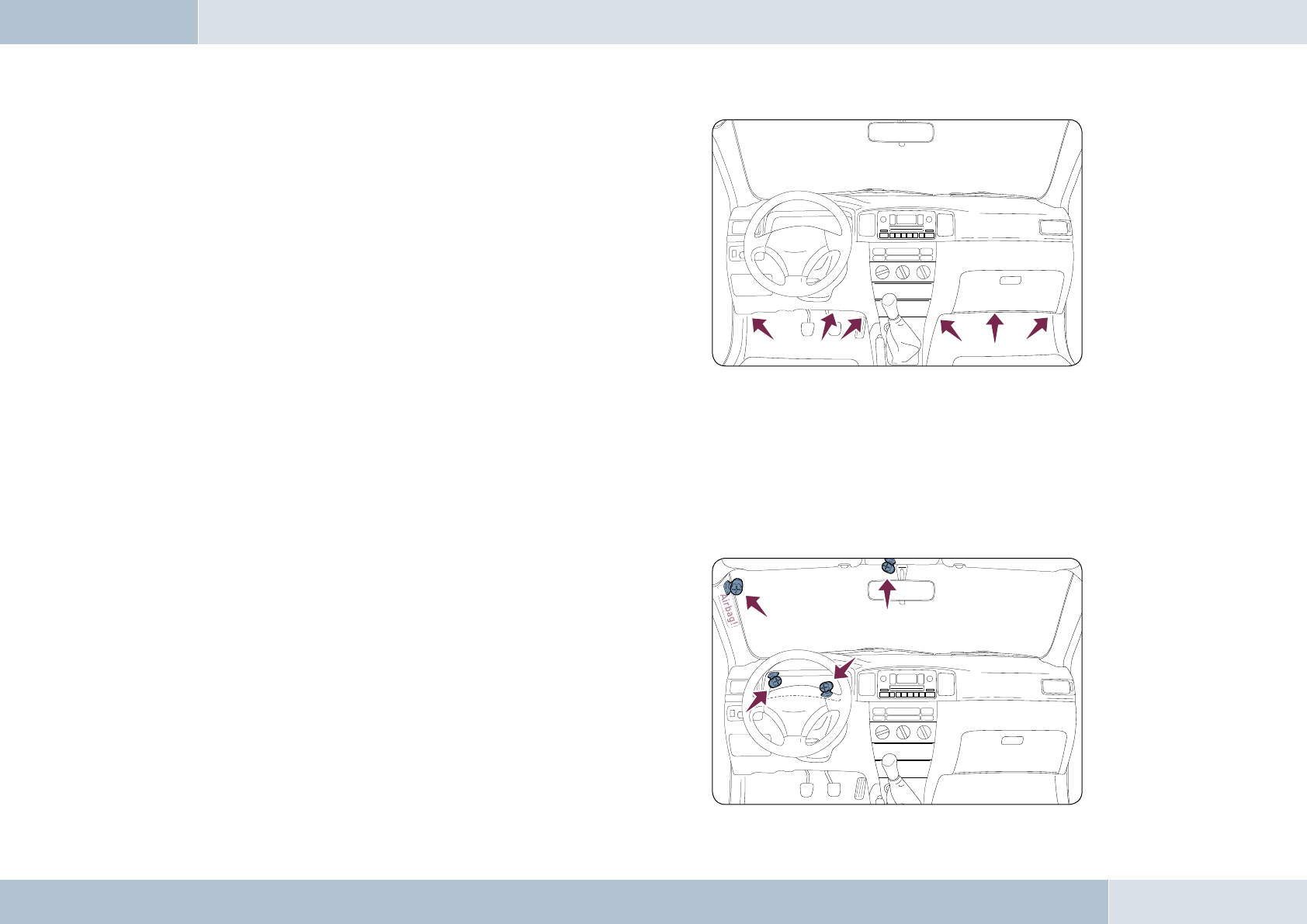
6.2.2 Selection of the installation location for the
electronics box
The Bluetooth® antenna for the connection to the mobile
phone is installed in the electronics box. The antenna
transmits directionally towards the front. For this reason,
q
Fig. 02:
Signal transmission of
the Bluetooth® antenna
EGO TALK
during installation, ensure that the antenna faces into
the passenger cell (see Fig. 02). Vertical mounting is
ideal. Metallic screening between the front panel and the
passenger cell, such as metal or metallised plastic panels,
are unsuitable and may interfere with the Bluetooth®
connection. Locations behind the dashboard or in a metal-
lined glove compartment are also unsuitable.
A covering in plastic, fabric or wood presents no problems
whatsoever.
Suitable locations for the electronics box:
Passenger side, next to the middle console under the
paneling, model-specifi c installation console (dealer).
Our suggested installation locations are shown in the illustration on the right.
Further unsuitable locations are:
Leg and knee height, potential head impact zone, airbag infl ation space, engine compartment
6.2.3 Selection of the point of installation for the microphone
Suitable for the microphone:
Where voice can reach the microphone unhindered (distance
between the speaker and the microphone should be
approx. 13.78 in), on the A-column (between windshield and
driver’s side window), next to the driver‘s sun visor, on the
dashboard
Unsuitable for the microphone:
Close to the speakers (less than 31 in), under the dashboard,
in the air stream from open windows or air vents.
10 | 11
Fig. 03:
Installation locations
for the electronics box
Fig. 04:
Installation location
for microphone
The illustration shows
one of the potential
microphone mounting
locations. Alternatively,
the microphone may
be attached to the
sun visor with the clip
provided.
6.2.4 Selection of the installation location for the control console
Suitable for the control console:
In the space above the DIN installation shaft, close to the steering wheel (in an easily accessible and visible position)
Unsuitable for the control console:
Airbag infl ation space, potential head impact zones, out of reach of driver’s reach
6.3 Installation
DAMAGE TO ESSENTIAL VEHICLE COMPONENTS! – Essential vehicle components or wiring can be damaged when
drilling mounting holes or screwing in self-threading screws. Please make sure there is always suffi cient space behind
the screw holes and drilled holes!
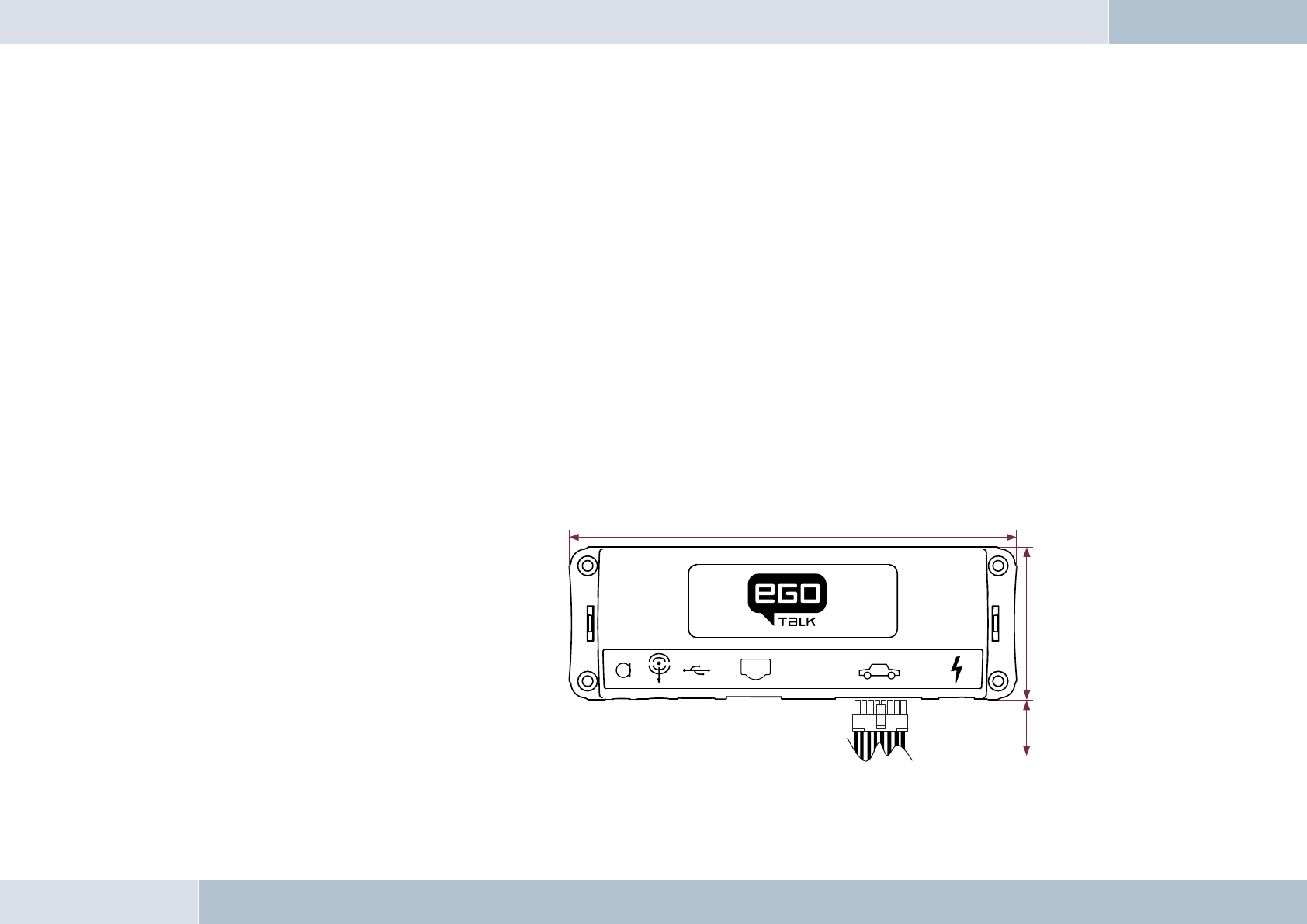
6.3.1 Mounting the electronics box
Installation consoles for a number of
car models are available from your
dealer. These are designed to contain all
the system components, including the
electronics box. When it is not possible
to use an installation console, please
proceed as follows:
Defi ne the mounting points
Making sure that there is at least 2.8 in
space for the plug and socket connectors.
Mark the positions for the fi xing screws.
q
2.76 in
1.77 in
5.12 in
Fig. 05:
Electronics box
dimensions
EGO TALK

Mounting the electronics box
For mounting the electronics box, use four self-threading screws and appropriate washers. We recommend size
“ST 2,9x25 DIN 7981”self-threading screws. These are ideal for the fi xing of the electronics box. Pre-drill the holes
with a 0.08 in drill.
6.3.2 Mounting the microphone
Defi ne the mounting location
The microphone holder has a self-adhesive strip on the back. The mounting location should have the same form and area
as the self-adhesive strip on the microphone holder. The location selected must allow the microphone cable to reach the
electronics box! Position the microphone with the head facing towards the direction of speech.
Cleaning and degreasing the mounting location
The mounting location must be clean and free from grease and dirt/dust. Prior to installation, clean the area with a
cleansing product containing ethyl alcohol. Only use products that do not damage plastics or varnished wood fi nishes
and are themselves free of oils or grease. Unsuitable cleansers are, for example, lighter fl uid, acetone, turpentine,
trichloroethylene and similar products.
Attaching the microphone holder
Peel off the protective backing from the self-adhesive strip. Hold the microphone holder at a distance of several
millimetres (about a quarter of an inch) above the desired mounting location. Re-check the positioning. Re-positioning
after mounting is no longer possible. Place the microphone holder on the mounting location and fi x by applying short and
light pressure.
Attaching the microphone
Attach the microphone by sliding it into the holder and position the microphone head towards the direction of speech.
6.3.3 Mounting the control console
Defi ne the mounting location
The control console is mounted on a smooth service by means of the self-adhesive pad provided. Make sure that the
location is within easy reach of the intended user.
12 | 13

Cleaning and degreasing the mounting location
The mounting location must be clean and free from grease and dirt/dust. Prior to installation, clean the area with
a cleansing product containing ethyl alcohol. Only use cleansing products that do not damage plastics or varnished
wood fi nishes and are themselves free of oils or grease. Unsuitable cleansers are, for example, lighter fl uid, acetone,
turpentine, trichloroethylene and similar products.
Attaching the control console
After defi ning the appropriate cable direction on the back of the console, fi x it by covering it with the self-adhesive pad.
Hold the control console at a distance of several millimetres (about a quarter of an inch) above the desired mounting
location. Re-check the positioning. Re-positioning the console after mounting is no longer possible. Apply the control
console to the proposed mounting location and fi x by applying short and light pressure.
6.4 Connection scheme
Installation for call reception for a car audio system with a mute input but without a phone input
With this connection option, voice playback is is emitted from the front right car speaker. During calls, the mute input
blocks the car audio signal.
NOTE: Please observe the information in section “6.5.1 Checking the mute inputs” on connecting the mute lead of the ISO
connecting cable.
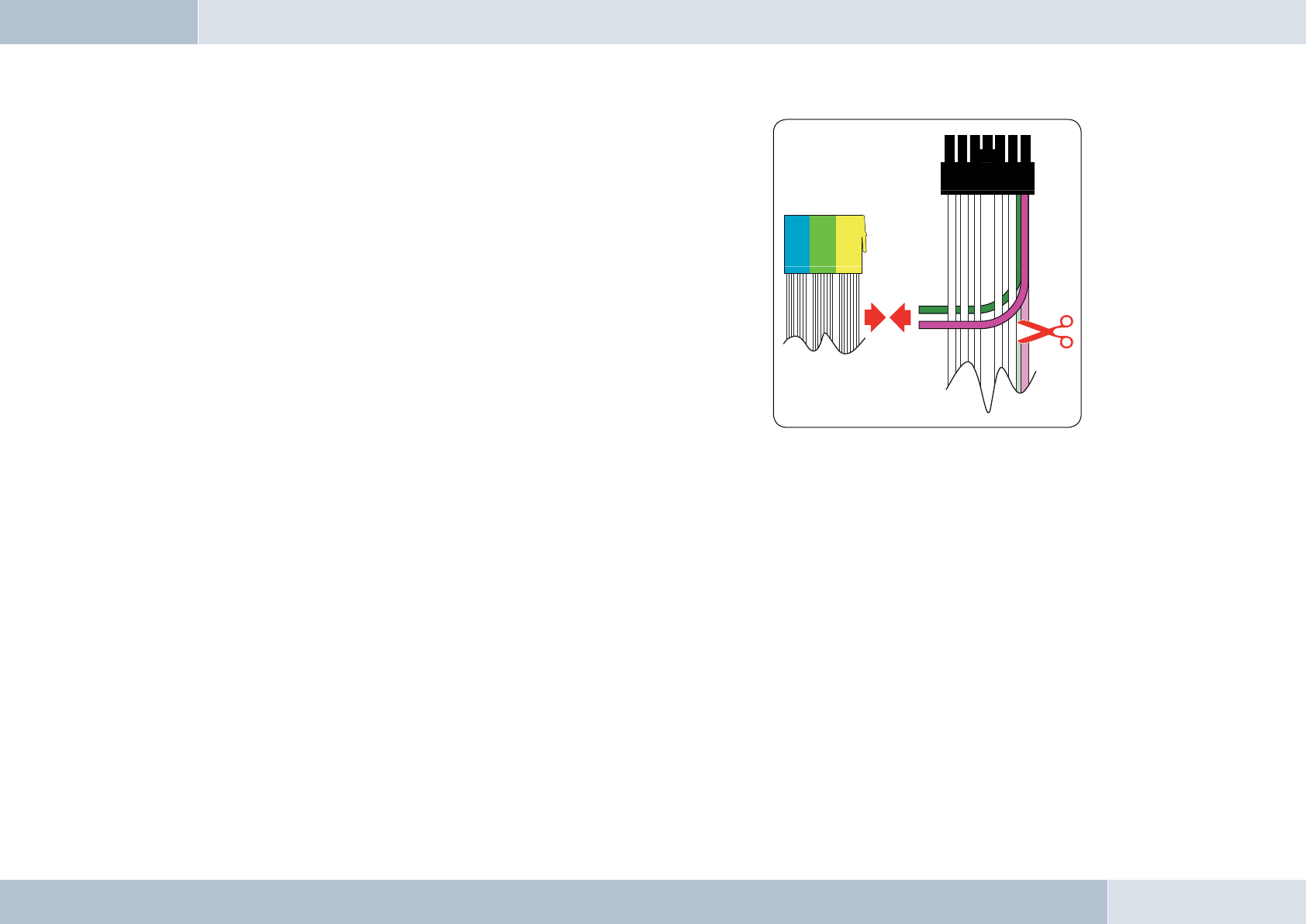
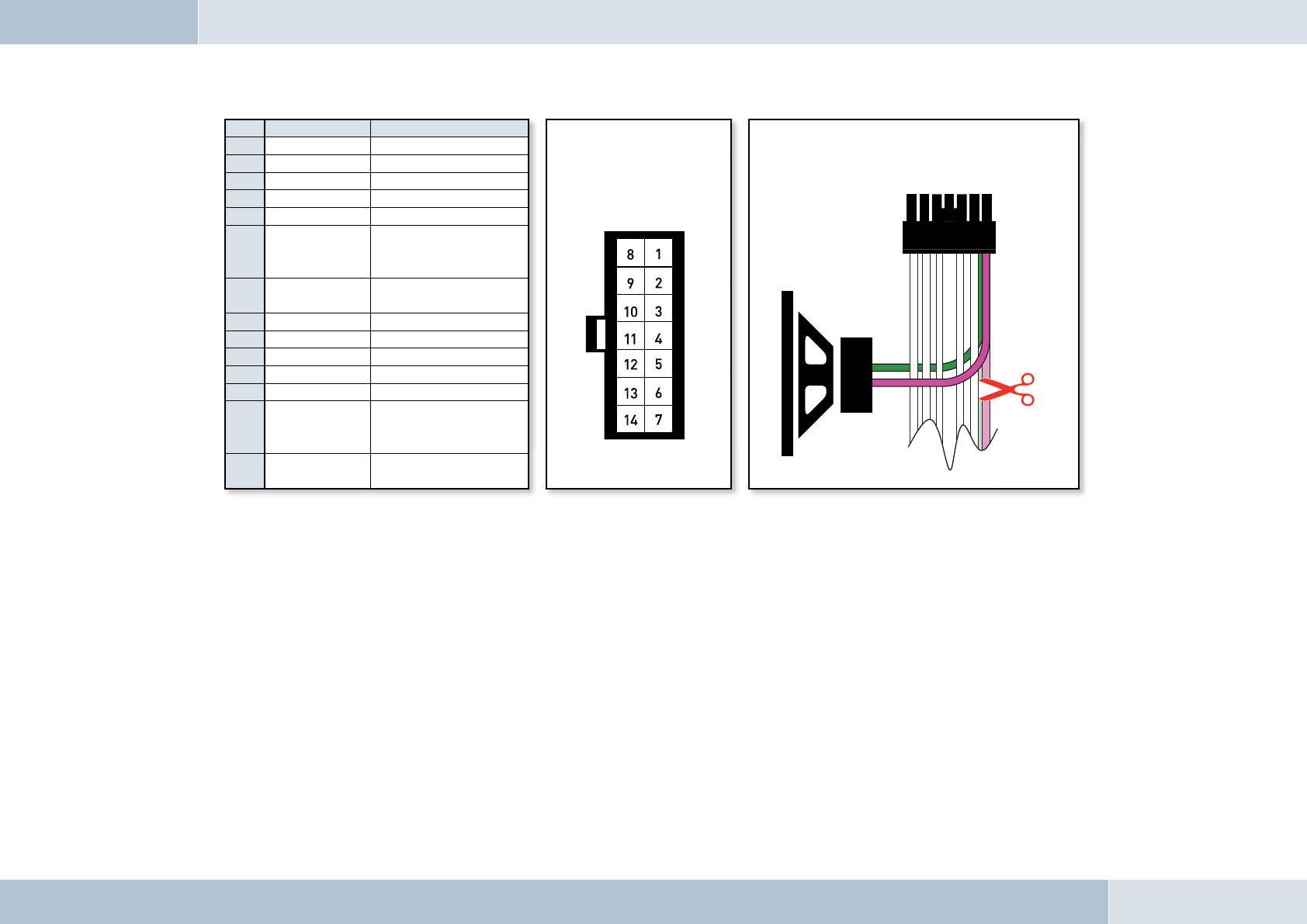
Installation for voice playback with a car audio system with phone and mute input options
With this connection option, voice playback comes through the car audio system speakers. During calls, the car radio
output is switched to the phone input by the mute input In order to access the phone input of your car audio system, the
speaker output of your EGO TALK must be connected to the phone input of your car audio system. The purple and green
leads of the ISO cable must be connected to the car audio phone input for this option. The purple and green leads must be
disconnected from the ISO connector. The green lead (pin 14 of the 14-pin plug) should be connected to „Phone Out“, and
the purple lead (pin 7 of the 14-pin plug) to „Phone In +“ of the Mini-ISO socket.
For information on the phone connection options of your car audio system, please consult the manufacturer‘s user manual.
q
EGO TALK
NOTE: If your car audio system has different phone connection
options from those mentioned here, please consult a qualifi ed
professional for installation of the system. Furthermore, please
read the section with information on connecting the mute lead of the
ISO connection cable, “6.5.1 Checking the mute input”.
q
14 | 15
Fig. 06:
Mini-ISO
connection
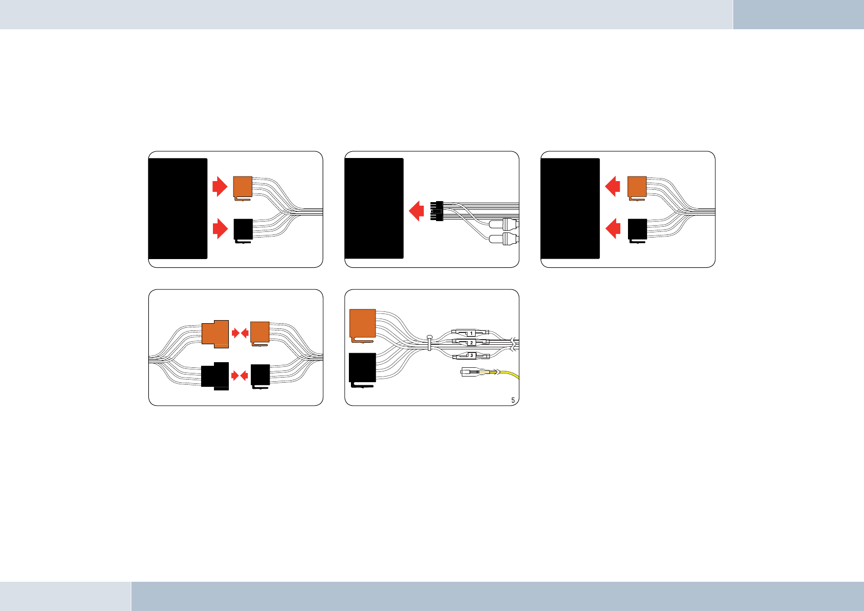
6.5 Installation of the ISO connecting cable
The battery must be disconnected before starting cable installation. Disconnect the grounding cable from the negative pole
of the battery. The cable installation procedure is shown in the illustrations.
When the installation is completed, reconnect the grounding cable to the negative pole of the battery.
6.5.1 Checking the mute inputs
Picture 5 of Fig. 07 shows mute inputs 1–3. The yellow mute lead of the hands-free system should be connected to one of
these inputs. Which mute input should be selected is shown in the tables:
Fig. 07:
Installation
procedure
1
2
3
4
Connect 14-pin ISO
connecting cable to
EGO TALK
Disconnect car wiring
harness from car radio
Connect EGO TALK ISO
connector to car radio
Connect EGO TALK ISO connectors to car
wiring harness ISO connectors
Connect yellow mute lead to
one of the three mute inputs
(see table)
Car audio
Car audio
Electronics box
EGO TALK
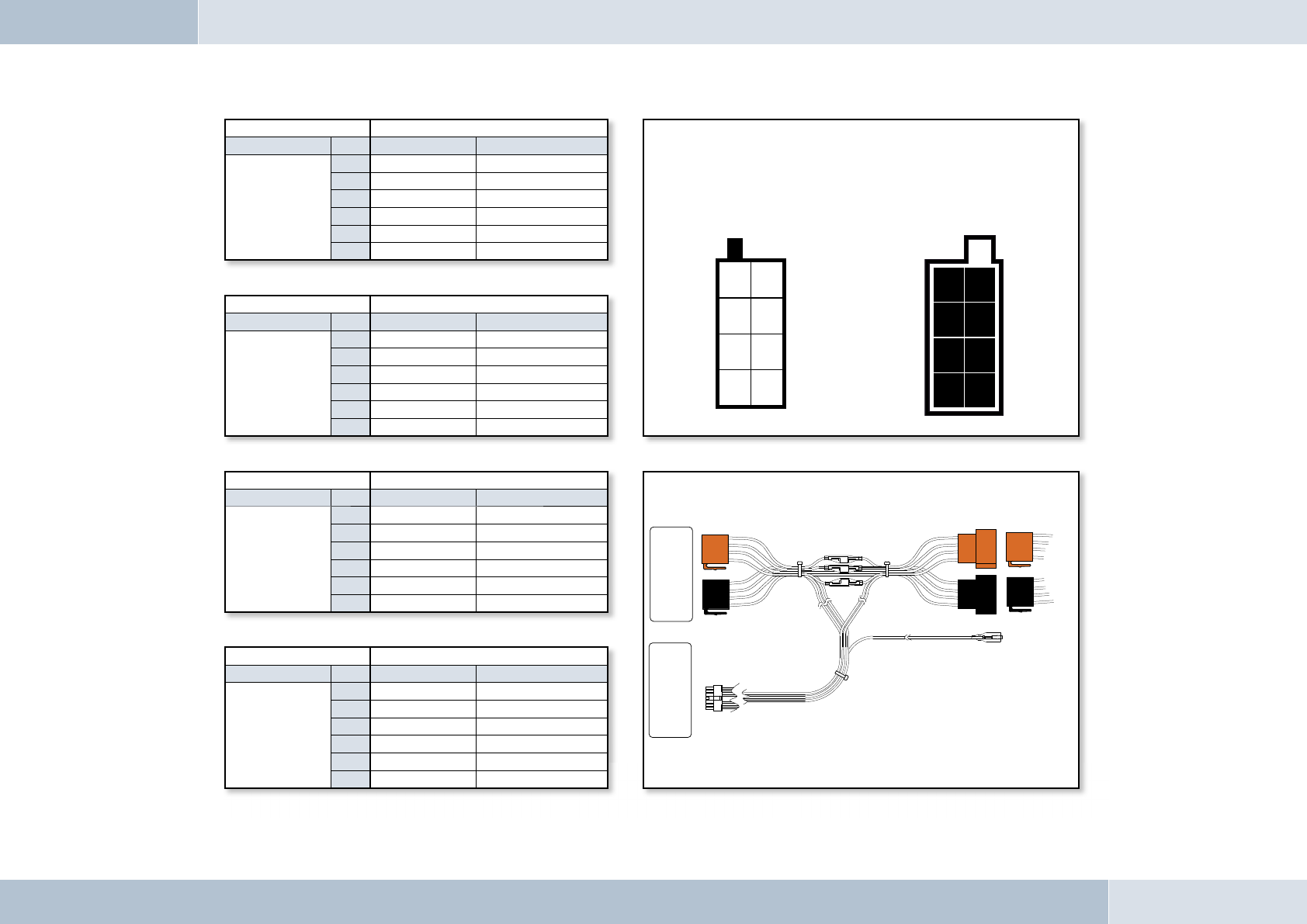
Fig. 08:
Type-
dependent
pin allocation
Fig. 10:
Connection system
Socket contact housing Wiring of power supply connectors
Radio model Pin Wire colour Function
Audi,
Volkswagen,
Grundig
1
2Mute
3
4blue Ignition (15)
7red Permanent positive (30)
8brown Ground (31)
Socket contact housing
Radio model Pin Wire colour Function
Ford,
Mercedes,
Porsche,
Becker
1
2
3Mute
4red Permanent positive (30)
7blue Ignition (15)
8brown Ground (31)
Socket contact housing
Radio model Pin Wire colour Function
Blaupunkt
1
2Mute
3
4red Permanent positive (30)
7blue Ignition (15)
8brown Ground (31)
Socket contact housing
Radio model Pin Wire colour Function
Philips
1Mute
2
3
4red Permanent positive (30)
7blue Ignition (15)
8brown Ground (31)
16 | 17
Socket wiring from
the rear (see table)
Plug wiring from
the rear
21
43
65
87
12
34
56
78
Autoradio
Elektronikbox
KFZ-Kabelbaum
Fig. 09:
Plug wiring scheme
Car audio
Electronics box
Vehicle wiring harness
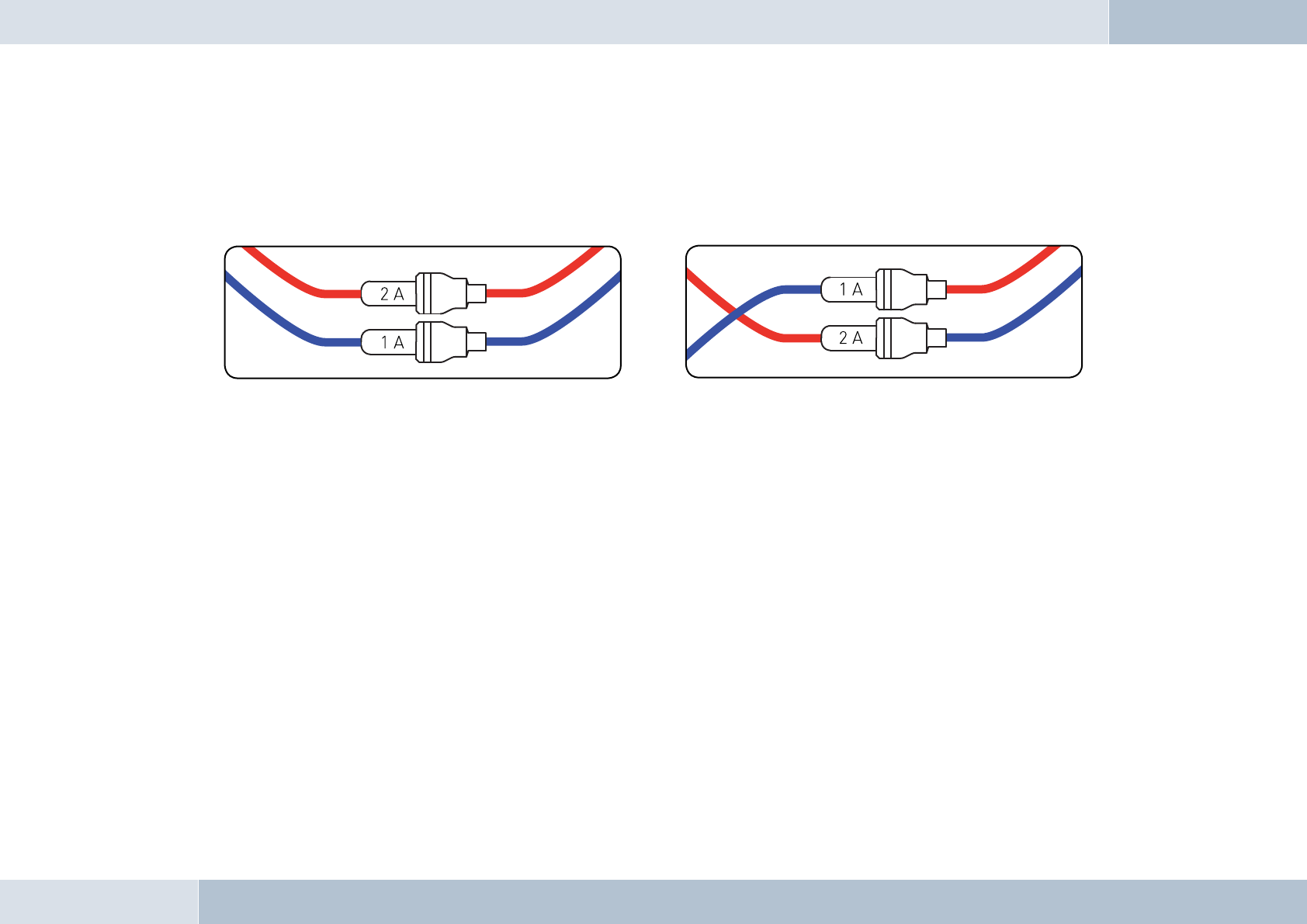
6.5.2 Checking the installation
When the ISO connection cable is correctly installed, a call remains active until the call is ended, even if the ignition has
already been turned off beforehand. The system switches off automatically when the call has been ended. If the system
switches to off immediately switches off,then exchange the ignition lead (blue) with the power supply lead (red) as shown in
Fig. 11b
PLEASE NOTE: the fuses should remain in place when opening the fuse compartment, make sure that they are not
inadvertently exchanged!
6.5.3 Additional external speakers
In the following cases, additional speakers (4 Ω, min. 5 W) must be used:
→ when the car audio system speakers should not be used
→ when the output rating of the speaker channel is greater than 35 W (Sinus) and the car audio
system has no phone connection option
→ when the car audio system is used with active speakers and has no phone connection option
Feedback interferes with the clarity of calls. Mount additional speakers at a distance of at least 31 in from the microphone.
When mounting additional speakers, please observe the manufacturer‘s installation instructions. Speakers can be
connected to the green (pin 14) and the purple (pin 7) leads of the connection cable. First of all, the purple and green leads
must be disconnected from the ISO connector (see Fig. 12).
q
Abb. 11a:
View of original
connection
Abb. 11b:
View after
changing cables
EGO TALK
6.6 Connecting the components to the electronics box
The individual components are connected to the electronics box as follows:
[1] Plug the microphone jack into the jack socket with the microphone symbol
[2] The electronics box line-out must be connected to the car audio line-in. Depending on the car audio line-in
confi guration, one of the following cables is required:
→ Connection cable 0.14 in stereo jack to 0.14 in stereo jack (l = 4.92 ft)
→ Connection cable 0.14 in stereo jack to RCA plug (l = 4.92 ft)
→ Connection cable 0.14 in stereo jack to Mini-ISO (l = 4.92 ft)
[3] The control console must be connected to the control console input.
Pin Colour Function View of the plug side,
from which the wiring is
fed in the plug housing
(with pin allocation)
Connection option for additional speakers on pin 7
(purple lead) and pin 14 (green lead) of the 14-pin plug
1Brown Ground (31)
2Yellow Radio mute
3
4
5
6White
Car audio speaker
output +
(front right)
7Purple Speaker lead +
(front right)
8Red Permanent positive (30)
9Blue Ignition (15)
10
11
12
13 Black
Car audio speaker
output -
(front right)
14 Green Speaker lead -
(front right)
18 | 19
Fig. 12:
Additional external
loudspeakers
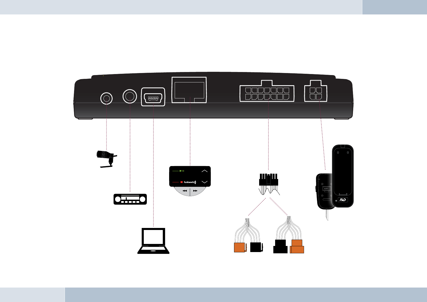
[4] The 14-pin plug of the ISO connecting cable must be connected with the electronics box.
[5] The base plate for the charging cradle may also be connected to the “charger” output socket.
[6] The USB port is exclusively reserved for servicing purposes.
Fig. 13:
Electronics box
connection
[1]
[2]
[3]
[6] [4]
[5]
EGO TALK

6.7 Operational test
An operational test is only possible after coupling the system with a Bluetooth®- compatible device. The procedure is
explained in the sections “7.3 Getting started” and “7.5 Audio Player” shown in the following pages.
20 | 21
User Guide
ROAD SAFETY RISK! Distracted attention can lead to dangerous situations in traffi c. Even when using hands-free phone
systems, your complete attention must be paid to the current traffi c conditions. It is always advisable to avoid phone
calls while driving in diffi cult traffi c situations!
7.1 Features
7.1.1 Overview of features
The hands-free EGO TALK system supports the Bluetooth® Hands-free Profile. This means that you can operate phones
that support this profi le with our system. EGO TALK is the intelligent entry-level solution for in-car telephony and offers
the following range of features:
→ Call functions, such as incoming/outgoing calls and redial
→ Supports mobile voice dialing
→ Music playback – playback of music fi les from mobile phones, iPods™ or MP3 Players via
Bluetooth® Audio-Streaming (A2DP)
→ Automatic radio muting
→ Registration of up to 8 mobile phones
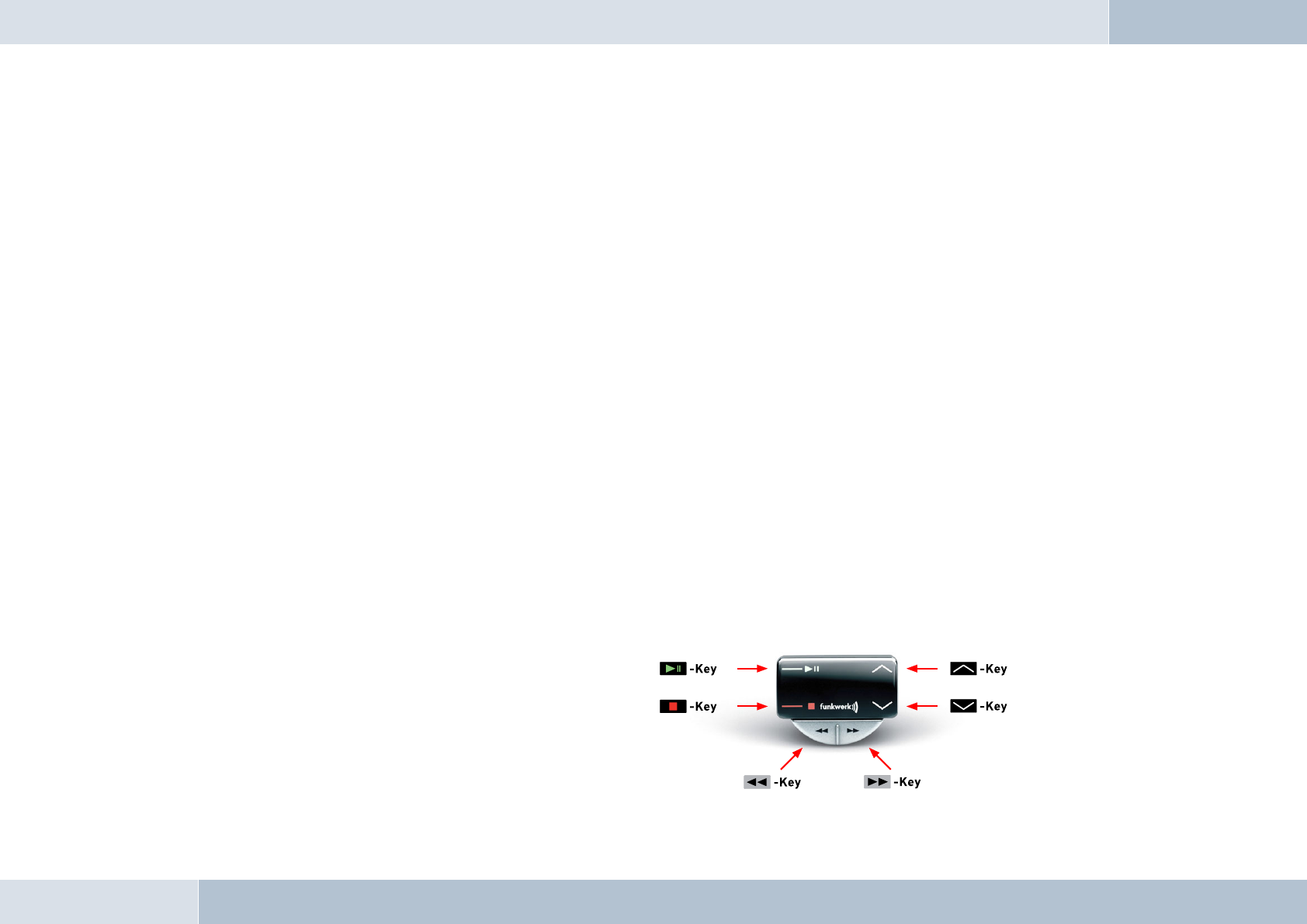
7. 2 S y m b ol s
The control console of the EGO TALK has a
total of six keys. The illustration on the right
shows an overview of the key locations. The
functions of the existing keys are explained in
the following section.
7
q
EGO TALK

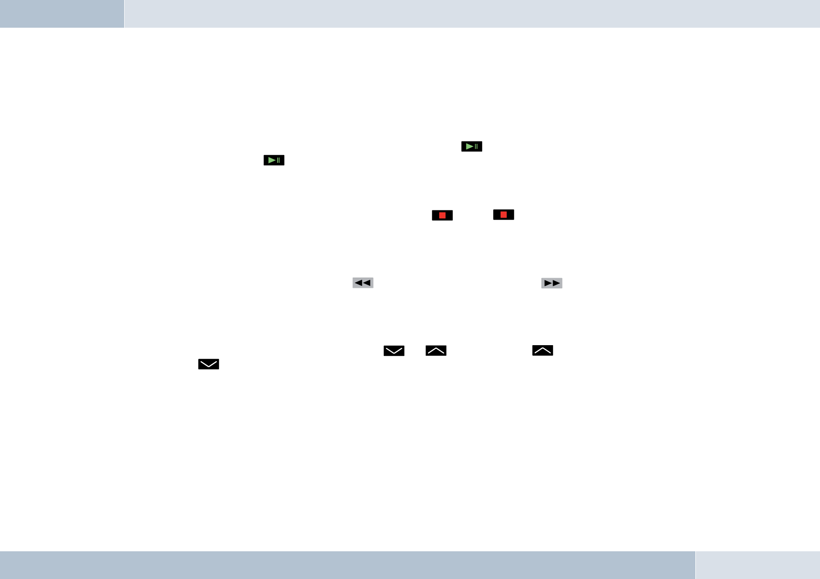
Key functions
→ The key (green) is for accepting calls. It also controls the redial function; if you have already
dialed a number from your phone, press this key to redial. When listening to music, this key controls
both the play and pause functions.
Functions: accept, redial, play, pause
→ The key (red) is used for rejecting incoming calls and ending completed calls (hang-up). During
music playback, this key controls the track stop function. This key is also the switching control
between hands-free mode and music control mode.
Functions: hang-up, reject, stop, switch between hands-free and music control
→ The key starts the phone‘s voice dialing function. It supports the features shown in the user‘s
manual of your mobile phone model. During music playback, the key performs the forward-skip
function. Only complete titles can be skipped.
Functions: start phone voice dialing function, forward skip
→ The key controls the reverse-skip function.
Functions: reverse skip
→ The key increases the volume in phone and music playback modes.
Functions: raise volume
→ The key decreases the volume in phone and music playback modes.
Functions: lower volume
22 | 23

LED indicators
Two different coloured LEDs (red and green) are integrated in the EGO TALK. The LEDs indicate the current status of the
system. The following combinations are possible.
LED Status
→ Green blinks at intervals → no device coupled
→ Both red and green steadily on → Hands-free connection enabled (hands-free mode)
→ Green only on → A2DP active (music mode)
→ Green steadily on and red momentarily off → Music playback stopped (Both profi les enabled,
hands-free mode)
→ Red steadily on and green blinks periodically → active call
7.3 Getting started
Take enough time to familiarize yourself with the use of the system in combination with your phone. First of all, make a
few calls to determine the ideal volume and the best voice pick-up direction before using the system in traffi c. The best
way of optimizing conditions of use is to park your car in a quiet place especially for this purpose. It is also helpful if
another phone user can take some time to assist you when making test calls.
7.3.1 About Bluetooth® technology
Bluetooth® technology is a wireless technology and allows, as such, communication between individual devices without
the need for cables. Data and voice information can be transmitted simultaneously. It is not unnecessary to have line-of-
sight routing between the devices. The transmission/reception range in the open is typically 32.8 feet. Interference from
other electrical or electronic equipment or obstacles may, however, reduce this range. The frequency band in which
Bluetooth® operates, is reserved virtually worldwide. This coupled with the fact that each Bluetooth® product is tested
and approved for compatibility with other Bluetooth devices, ensures the highest possible levels of compatibility with
devices from a wide range of manufacturers. The EGO TALK supports the Bluetooth® Hands-free Profi le. This means
that it is fully compatible with all phones supporting the Bluetooth® Hands-free Profi le. If uncertain, read the User Guide
of your mobile phone to see which profi les are supported.
EGO TALK

A2DP (Advanced Audio Distribution Profi le) is a technology that enables the wireless transmission of stereo audio
signals via Bluetooth® to a compatible receiving device. Please take a look at our homepage for information about
compatible mobile phones.
7.3.2 On / Off function
Turning the ignition key simultaneously activates the hands-free system. Immediately after the system is activated, the
two LEDs blink four times. This indicates that the system is in standby mode and ready to make a connection. In order
to use the system for phone calls, a Bluetooth® compatible phone must be coupled to the EGO TALK system. How this
is done is explained in detail in the following sections. When the ignition is turned off, the hands-free system also shuts
down. If the ignition is turned off during a call, the phone’s capabilities are maintained and the system only shuts down
when the call has been completed.
7.3.3 Coupling
A mobile phone intended for use with the hands-free system must be coupled to the EGO TALK. As long as no devices
are connected, the system is visible for all Bluetooth® devices. In this state, the green LED blinks every 7.5 seconds to
indicate that no devices are connected. The telephone to be used must be registered with the EGO TALK. The Bluetooth®
search and coupling procedure is initiated from the telephone. Die Bluetooth® code is “EGO TALK”. The default input
PIN is “0000”. When the connection/coupling procedure is successfully completed, both diodes are steadily on. One
phone per user may be coupled. If you wish to couple an additional phone, use your initial phone to decouple the current
connection. Should you encounter problems while coupling, please read the section “Solving Problems”, and take a look
in your phone manual at the section about Bluetooth® operations.
7.3.4 Automatic coupling
If a phone is already connected with the system, the EGO TALK tries to couple to this phone. When a connection has
been successfully made, the two LEDs are steadily on. The connection is always made to the most recently coupled
phone. If this phone is out of range, the system will search for other phones registered in the system. When the search is
successful, the connection to this phone is completed automatically. If the search process was unsuccessful, the system
reverts to the coupling mode. This enables manual connection from the phone.
24 | 25

7.4 C a ll i n g
7.4.1 Incoming call
When an incoming call is received, the ring tone is audible over the EGO TALK. At the same time, the green LED blinks
periodically. Pressing key accepts the incoming call. If the call is to be rejected, press the key. When the
system registers an incoming call during audio playback, the system automatically switches to hands-free mode. After
completion of the call, you can revert to audio playback mode by pressing key to restart the player.
7.4.2 Outgoing call
There are various options for initiating a call. Pressing the key starts the phones redial function and dials the last
number called. When the connection has been made, the green LED blinks periodically. Pressing the key initiates
the phone‘s voice dialing mode. You can now verbally give the number, name or commands supported by your phone. The
green LED also blinks periodically in this mode when the call has succesfully been placed.
The third option is direct dialling from the mobile handset.
IMPORTANT NOTE: Please observe your country‘s regulations on in-car telephone use!
7.5 Audio Player
7.5.1 Coupling
Coupling with music players varies from model to model. If you are using a phone that supports both hands-free and
A2DP, there is no need to repeat the coupling procedure, because the phone is already coupled to the system. However,
when using a player that does not support A2DP (MP3 Player), this must be equipped with a separate A2DP adapter. In
the case of such players, there may be no connection between the EGO TALK and your phone when coupling for the first
time, otherwise the stand-alone device will be unable to find the EGO TALK unit. In this case, the connection to the phone
must be disabled. Once the device has been recognised, a direct connection will be made to your EGO TALK, even when
q
EGO TALK
a phone connection already exists. A2DP compatible phone models differ in the method of starting music players. You
can find more information on this subject on our homepage.
7.5.2 Play / Pause
When an A2DP player is connected and the player has been started, the key starts music playback. Playback can be
temporarily stopped by the key (pause function) and resumed by repressing the same key (resume function).
7.5.3 Stop
Playback can be stopped when listening to music by pressing the key. The key can also be used to stop music
playback and switch to hands-free mode.
7.5.4 Skip function
If you wish to skip forward one track, press the key. To skip back one track press the key.
7. 6 Vo lu me
The volume of audio playback can be controlled by the and keys. Pressing the key raises the volume,
pressing the key lowers the volume.
26 | 27

Service
FAQ – List of frequently asked questions:
1. How big are the displays and/or control consoles?
You can fi nd the dimensions in the “Technical specifi cations”.
2. Are EGO systems suitable for all car models?
Yes, EGO systems are suitable for all cars. See the installation guide!
3. Is there a list of optional charger cradles?
Yes. You can fi nd a list of the available holders on our homepage.
4. Where can I buy EGO systems?
Through an authorized dealers. You canlocate the nearest authorized dealer online,
just click on Dealer → Dealer Search.
5. How are fi les exported for music playback?
EGO TALK can play music fi les over A2DP. But if your MP3 player doesn‘t have A2DP,
you will need an A2DP adapter. You can make your MP3 player or iPod™ Bluetooth®
compatible with a dongle/adapter.
6. Do EGO systems have an external antenna option?
Your mobile phone can be connected to an external antenna in conjunction with our
charging cradle, available as an optional accessory.
8
EGO TALK
28 | 29
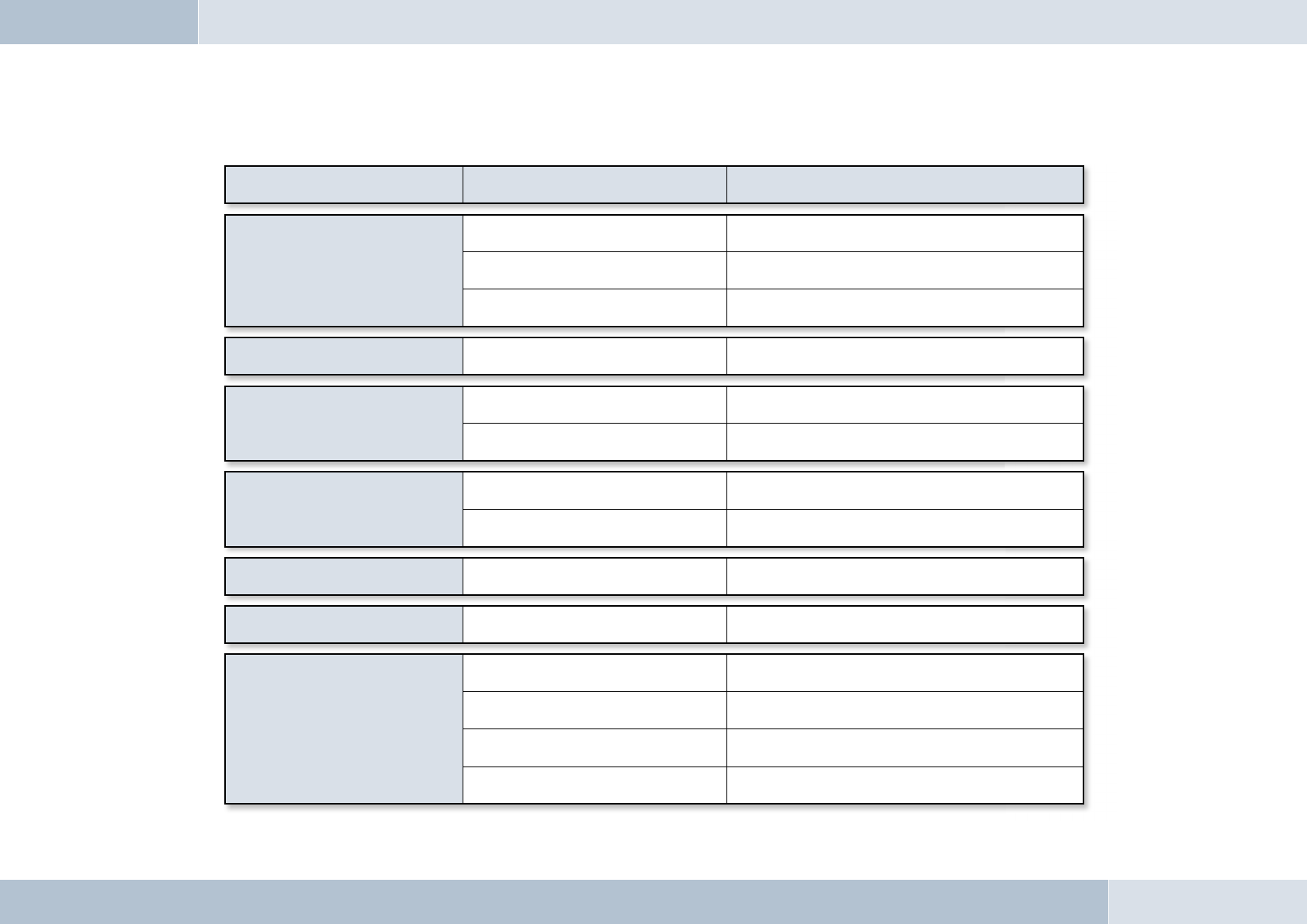
Problem Ursache Abhilfe
EGO TALK doesn‘t
turn on
Power supply disabled If necessary, replace fuse and check all leads and connections
Ignition not on Turn ignition on
Ignitions circuit disabled Check cable and 1 A fuse
The party you are calling cannot hear you Microphone not plugged in Connect microphone to electronics box,
defective cables require replacement
The party you are calling complains about
interference
Microphone in air stream Mount microphone elsewhere or reduce ventilation
Phone too close to EGO TALK
components or car radio
Increase the distance between your phone and
the EGO Talk or radio
The party you are calling hears an echo
Distance between microphone and
speakers too small Increase distance or lower volume
Volume too high Lower volume
Your phone cannot fi nd
EGO TALK during coupling EGO TALK already connected to another device Disconnect existing connection
Sound is unclear, distorted Poor Bluetooth® connection Reduce the distance between your phone and the EGO TALK or
remove any (metallic) obstructions
No connection to coupled
phone when ignition turned on
Phone is out of range. Make sure your phone is within the range of the EGO TALK.
Phone Bluetooth® interface is deactivated. Switch phone Bluetooth® function to ”ON“
(Option ”Automatic“ is not suffi cient)
Phone requires confi rmation
of connection set-up.
Confi rm connection on your phone. Deactivate security function
(see your phone manual)
One of the two devices no longer has
a valid connection code. Repeat the coupling procedure.
Troubleshooting:
Spares parts and accessories
You can fi nd out more about supported mobile phones on our website at www.fwd-online.de. Your dealer will also be happy
to advise you if you have any questions.
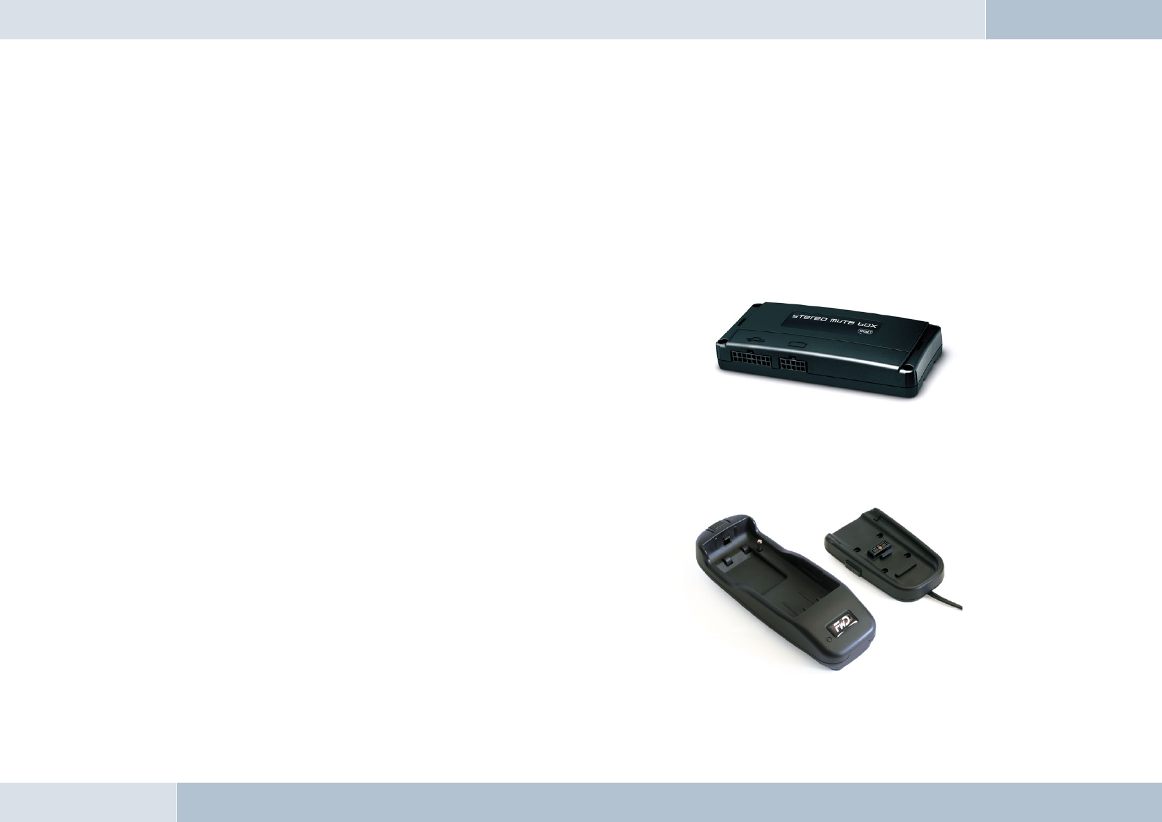
Accessories:
Stereo Mute Box
Relax and listen to music or phone from your car. The Stereo Mute
Box provides smart sound management. This compact box plays your calls
or music over the car‘s speakers – of course in superb stereo sound. The
car radio is muted during calls or when listening to music.
Features:
- Radio muting during calls or music playback (Audio Streaming)
- Stereo music reproduction in combination with the car‘s front speakers
- Phone audio over the front speakers
Base plate with charging cradle
The charging cradle is a practical accessory for Bluetooth® hands-free
systems by Funkwerk Dabendorf. The charging cradle holds your mobile
phone fi rmly and allows you to recharge its batteries in your car and is
an ideal accessory for drivers who are constantly on the road and often
need their phones. In addition, the external antenna connection ensures
outstanding reception and transmission.
Features:
- Intelligent charging circuit for mobile phones
- Mobile phone safely and securely held in the charging cradle
- External antenna connection for excellent call quality
9
EGO TALK
30 | 31
Replacement parts:
[1] Electronics box
[2] Control console
[3] Microphone
[4] Cable connection set
[5] Adapter cable
[1] [2]
[3]
[4]
[5]

Technical specifi cations
External dimensions: Electronics box 5.1 in x 1.8 in x 0.9 in
External dimensions: Control console 1.8 in x 1.3 in x 0.7 in
Cable length: Control console 6.6 ft
Operating voltage 11 V to 15 V
Quiescent current (ignition off) max. 0,1 mA
Fuse: Permanent positive 2 A
Fuse: Ignition 1 A
Temperature range 14 °F to 131°F
Supported Bluetooth® Profi les Handsfree, A2DP, AVRCP
Certifi cation
0681
Fully compliant with the EU R&TTE Directive 1999/5/EC
Model certifi cation according to EU Directive 72/245/EWG (2006/28/EC) “Electromagnetic compatibility in motor vehicles”
Bluetooth® is a registered brand name of Bluetooth SIG, Inc.
10
11
03 5010
EGO TALK

32 | 33
Conformity statement
This equipment employs Bluetooth® wireless technology. In some countries, the use of this equipment may be restricted
or forbidden. Please make sure you are familiar with such restrictions and do not use your equipment if you are unsure
whether its use is permitted in particular countries you may be visiting.
Bluetooth® is a registered brand name of Bluetooth SIG, Inc.
Funkwerk Dabendorf GmbH
Märkische Straße
D-15806 Dabendorf
Confi rms that the hands-free system “EGO TALK” complies with
the fundamental requirements and other relevant regulations of
the EU Directive 1999/5/EC.
0681
12

EGO TALK
FCC statements
This device complies with part 15 of the FCC Rules. Operation is subject to the following two conditions: (1) This device may
not cause harmful interference, and (2) this device must accept any interference received, including interference that may
cause undesired operation.
NOTE: This equipment has been tested and found to comply with the limits for a Class B digital device, pursuant to
Part 15 of the FCC Rules. These limits are designed to provide reasonable protection against harmful interference in a
residential installation. This equipment generates, uses and can radiate radio frequency energy and, if not installed and
used in accordance with the instructions, may cause harmful interference to radio communications. However, there is no
guarantee that interference will not occur in a particular installation. If this equipment does cause harmful interference to
radio or television reception, which can be determined by turning the equipment off and on, the user is encouraged to try to
correct the interference by one or more of the following measures:
→ Reorient or relocate the receiving antenna.
→ Increase the separation between the equipment and receiver.
→ Connect the equipment into an outlet on a circuit different from that to which the receiver is connected.
→ Consult the dealer or an experienced radio/TV technician for help.
WARNING: Changes or modifi cations made to this equipment not expressly approved by FWD may void the FCC
authorization to operate this equipment.
FCC Radiation Exposure statement:
This equipment complies with FCC radiation exposure limits set forth for an uncontrolled environment. End users must
follow the specifi c operating instructions for satisfying RF exposure compliance.
This transmitter must not be co-located or operating in conjunction with any other antenna or transmitter.
q
q

Hotline
Any questions, comments, or suggestions? Would you like some more detailed information? Do you need an adviser or
service in your area? Just give us a call!
Our service hotline is there to help you during the following times:
Monday–Thursday from 7.00 a.m. to 5.00 p.m.
Friday from 7.00 a.m. to 4.00 p.m.
Before you call us with your problem, please check fi rst with the following steps:
→ Check whether you can solve your problem with the „Troubleshooting“ checklist in Chapter 8.
→ Make sure you have your hands-free system and holder set type available.
→ Try to explain your problem as precisely as possible.
You can contact our service hotline by dialing:
From Germany: Phone: 0800 - 0 393 393
From outside Germany: Phone: +49 (0) 3377 - 316 233
+49 (0) 3377 - 316 234
Fax: +49 (0) 3377 - 316 244
13
34 | 35

A Funkwerk AG company.
Funkwerk Dabendorf GmbH
Märkische Straße
15806 Dabendorf
Germany
Phone +49 (0) 3377 316 - 0
Fax +49 (0) 3377 316 - 300
Email info@fwd-online.de
Internet www.fwd-online.de
Funkwerk Dabendorf reserves the right to modifi cations in the course of technological progress and deviations from the delivery scope! All rights reserved! Reproduction, in whole or in part,
is only permitted with the prior written consent of Funkwerk Dabendorf GmbH!