Molex CVS Dabendorf 156-01 Bluetooth Handsfree Car Kit User Manual 15680001 01
Novero Dabendorf GmbH Bluetooth Handsfree Car Kit 15680001 01
UserMan
Handsfree System
156 8000 1.00
Installation
Instructions

-2-
Audio 2010
Funkwerk Dabendorf GmbH
Märkische Straße
D - 15806 Dabendorf
Phone: +49 3377 316 - 0
Fax: +49 3377 316 - 300
info@fwd-online.de
www.fwd-online.de
Rights to changes and deviations from the scope of delivery reserved as required by technical pro-
gress! All rights reserved! Copies, also excerpt-related, only with written approval!

-3-
Table of contents
Audio 2010
Table of contents
1. Notes on safety ........................................................................ 4
2. Introduction .............................................................................. 6
3. Scope of delivery ..................................................................... 7
4. Technical data .......................................................................... 8
5. Certifications ............................................................................ 8
6. Installation ............................................................................... 9
6. 1. Identify prerequisites ................................................................. 9
6. 2. Selecting installation locations of the components .................. 10
6. 3. Preparation for installation of the components ........................ 13
6. 4. Fastening of the electronic box ................................................ 13
6. 5. Mounting microphone .............................................................. 14
6. 6. Installation of the display and actuator ..................................... 15
7. Connection to the vehicle electronics using an
adapter cable .......................................................................... 18
7. 1. Installation of the ISO connection cable .................................. 18
7. 2. Checking the installation .......................................................... 20
7. 3. Installation with additional ISO(2Car) adapter .......................... 21
7. 4. Installation with the aid of a vehicle-specific
connecting cable ...................................................................... 22
8. Connection to the vehicle electronics by separate
wiring of the lines .................................................................. 23
8. 1. Reproduction over the phone connection of the car radio ....... 24
8. 2. Reproduction over an external loudspeaker ............................. 25
8. 3. Reproduction over the loudspeakers of the car radio .............. 26
9. FAQ - Frequently Asked Questions ...................................... 27
10. Spare parts and accessories ................................................. 29
11. Declaration of Conformity ..................................................... 31

-4-
Audio 2010
Notes on safety
1. Notes on safety
Incorrect installation
Incorrect installation can lead to damage to the device or to the
vehicle! Special knowledge and capabilities are necessary for the
installation of the handsfree system. Incorrectly connected cables
or short-circuit can result in serious device damage. Before you
begin with the installation, the car battery is to be disconnected. It
is urgently recommended to have the installation carried out in a
specialist workshop.
Danger of injury
Unsuitable installation locations can cause injuries in case of a road
accident or make safety systems ineffective. Consider the refe-
rences in the Chapter „Installation“!
Danger of injury / material damage
When levering out paneling, pointed or sharp tools can result in inju-
ries and material damage. Lever out parts carefully. Do not place
any direct pressure on connection cables!
Impairment of traffic safety
Inattention can lead to dangerous traffic situations. Also in the
handsfree mode, you must always pay attention to the traffic situa-
tion. The telephone may be used by the driver during driving in
handsfree mode only! Dispense with a telephone call in difficult
situations, as appropriate!
Damage to the airbag
If an incorrect installation location is selected, the airbag can be
damaged or impaired in its function. Attach the components out-
side of the area of influence of the airbags!

-5-
Notes on safety
Audio 2010
Insulation damage
Damaged insulation can lead to device damage. In their layout posi-
tion, the cables may not be subjected to tension. Route the cables
so that they are not squeezed or rub against objects.
Damage of important vehicle parts
With the boring of fastening holes or screwing in sheet metal
screws, important vehicle parts or lines can be damaged. Pay atten-
tion to sufficient installation free space, also behind the boltholes
and drilling holes.
Influence of the on-board electronics
In spite of high radiation-emission security, influences of the on-
board electronics can result in case of inappropriate installation.
Consider the references of the vehicle manufacturer!
Damages through incorrect spare parts
Incorrect spare parts or replacement parts can lead to faults.
Employ only those parts listed in the section „Spare parts and
accessories“!

-6-
Audio 2010
Introduction
2. Introduction
Many thanks for choosing a handsfree system from Funkwerk Dabendorf
GmbH!
Our communication solutions make an important contribution to traffic safety
and to the convenient use of your mobile telephone in the car.
The Audio 2010 offers you the possibility to operate different mobile telephones
in your vehicle with the same universal system. This is achieved through the
Bluetooth
®
radio transmission standard.
Before the installation of the „Audio 2010“ in your vehicle, please insure that
your telephone interacts with it correctly. Where appropriate, inquire with your
dealer or your specialist workshop. Our service is also glad to remain available to
you for information. You can find further information on compatibility with diffe-
rent mobile telephones on our website.
To increase the operating convenience and your security with making a call while
driving, the Audio 2010 is provided with an interactive voice-activity detection.
Please note that special knowledge and capabilities are necessary for the instal-
lation of this handsfree system.
Proceed as follows with the installation
First of all check whether all parts are completely present as indicated in the illu-
stration overleaf. Lay out the necessary tools before the installation. Determine
the installation locations for the respective components based on the criteria
described in the Chapter „Installation“. Then install the handsfree system in the
car according to the installation instructions.
After installation
After the installation, take some time and make yourself familiar with the opera-
tion of the system. Make some telephone calls, where you can determine the
optimal conditions for volume and speech direction before you use the hands-
free system in road traffic.
We wish you a lot of success!
-7-
Scope of delivery
Audio 2010
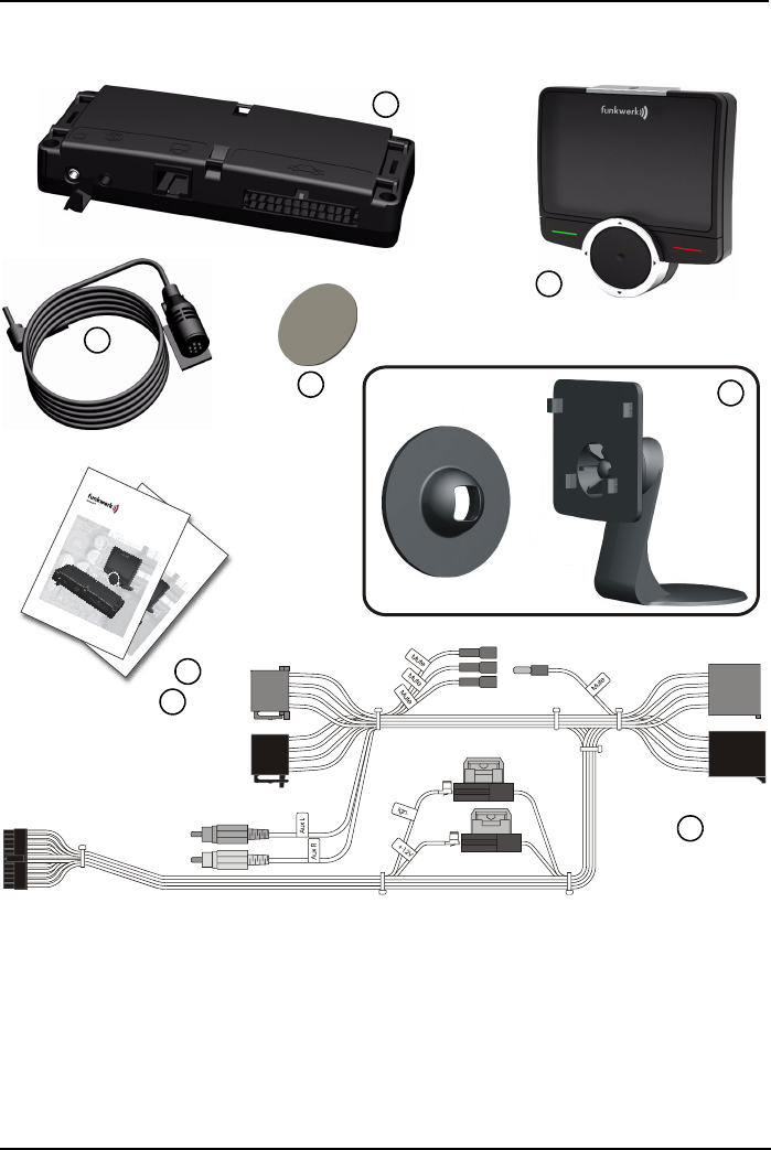
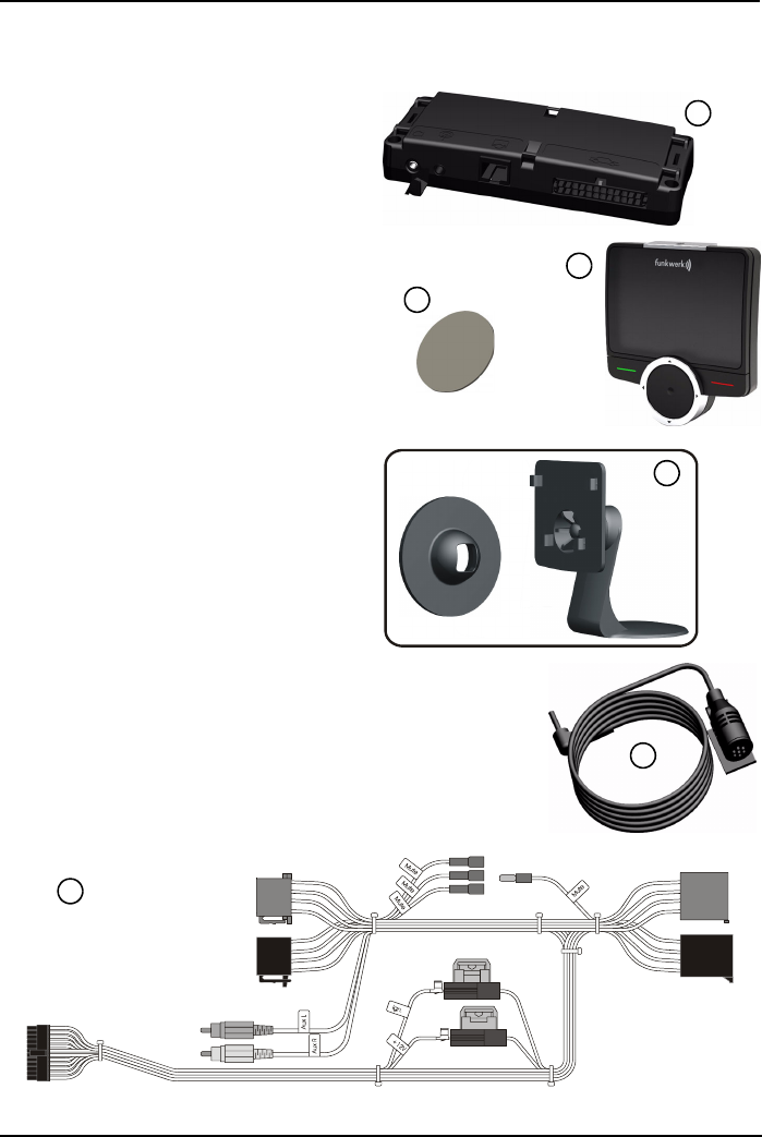
3. Scope of delivery
*) according to supply variant
1
2
3
4
Funkwerk Dabendorf GmbH
Freisprechanlage Audio 2010
156 8000 0.00
Audio 2010
Bedienungsanleitung
Funkwerk Dabendorf GmbH
Freisprechanlage Audio 2010
156 8000 0.00
Audio 2010
Einbauanleitung
6
7
5
8
1 - Electronic box
2 - Actuator with OLED display
(cable length 2m)
3 - Microphone (cable length 2,5m)
4 - Adhesive pad
5 - Installation set
6 - Installation instructions
7 - Operating manual
8 - ISO connection cable *)
(cable length 1m)

-8-
Audio 2010
Technical data
4. Technical data
Electronic box dimensions 131,9mm x 54mm x 23mm
Display dimension 55mm x 61,9mm x 21mm
Operating voltage 11 V to 15 V
Quiescent current take-up max. 0,1 mA
Operating current level max. 750 mA
Fuse 2 x 5A
Temperature range -10 °C to +55 °C
5. Certifications
e-Approbation
Type approval in accordance with Directive:
72/245/EWG (2009/19/EG)
„Electromagnetic compatibility in MOTOR VEHICLES“
This device complies with part 15 of the FCC Rules. Operation is sub-
ject to the following two conditions:
1. This device may not cause harmful interference, and
2. This device must accept any interference received, including
interference that may cause undesired operation.

-9-
Installation
Audio 2010
6. Installation
6. 1. Identify prerequisites
Vehicle
The system may be installed only in vehicles with an in-vehicle voltage of 12 V,
minus pole to ground. If no car radio is existing, an external loudspeaker is neces-
sary.
Telephone
In order to enable operation of this system, a Bluetooth
®
compatible telephone
must be used.
Muting (radio mute switching)
The muting function ensures that the radio sound volume is switched off during
a telephone call. The muting is supported by the system. You can find out in the
documentation on the car radio whether your car radio has a muting connection.
The mute signal is a ground signal!
External loudspeaker / phone connection of the car radio
The switchover of the radio loudspeakers to the system is implemented through
switching contacts. These are designed for a maximum loudspeaker power of 35
W (sine). Loudspeaker powers above 35 W lead to premature wear of the swit-
ching contacts. Use either the telephone input of the car radio, or an external
loudspeaker at higher output power (5 W / 4
Ω)
.
Checking cable lengths
Before you attach the components permanently, check whether the mounting
locations are selected so that the cable lengths are sufficient in order to connect
the individual parts with each other. Consider the following references in the sti-
pulation of the installation locations.
Incorrect installation
Incorrect installation can lead to damage to the device or the
vehicle! Special knowledge and capabilities are necessary for the
installation of the handsfree system. Incorrectly connected cables or
short-circuits can lead to serious device damage. Before you begin
with the installation, the car battery needs to be disconnected.
It is urgently recommended to have the installation carried out in a
specialist workshop.
-10-
Audio 2010
Installation
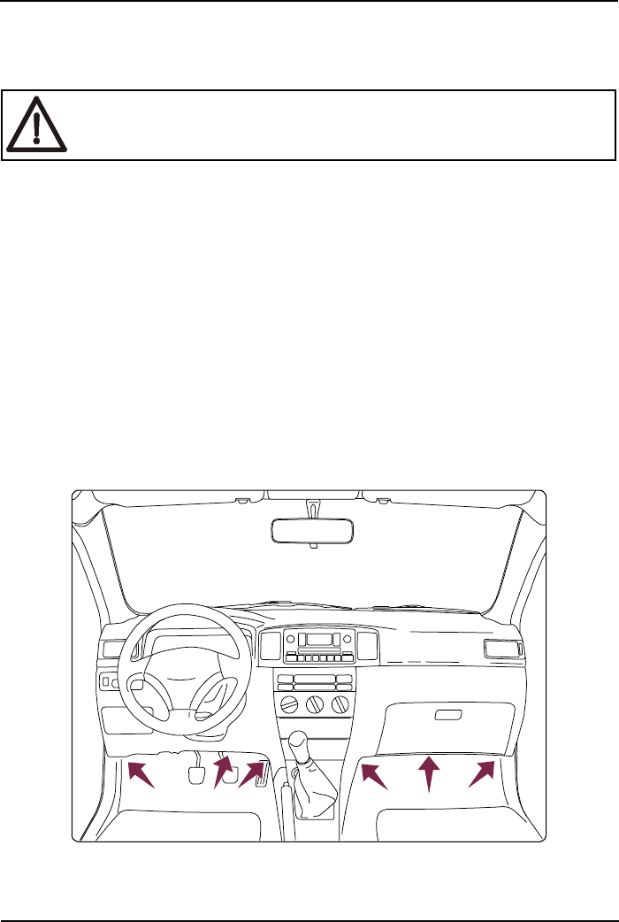
6. 2. Selecting installation locations of the
components
Selection of the installation location for the electronic box
In the electronic box an antenna is installed for the radio link to the mobile tele-
phone. The radiation emission is implemented mainly in the direction of the front
panel, therefore it should be mounted with installation in the passenger compart-
ment, facing in. A vertical installation is optimal. Metallic shielding between the
faceplate and the passenger compartment, such as panels of metal or metal
coated plastics, impair the link to the mobile telephone.
Suitable for the electronic box:
•Passenger area near the central console under the paneling
•Vehicle-specific installation console (specialist retailing)
•Behind the glove compartment
Danger of injury
Unsuitable installation locations can cause injuries in case of a road
accident, or make safety systems ineffective!
-11-
Installation
Audio 2010
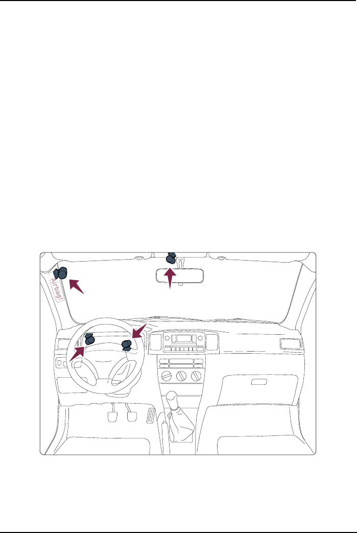
Unsuitable for the electronic box:
•Leg and knee area
•Possible impact area of the head
•Area of influence of the airbag
•In the engine compartment
•Behind the radio
•Near the fuse box
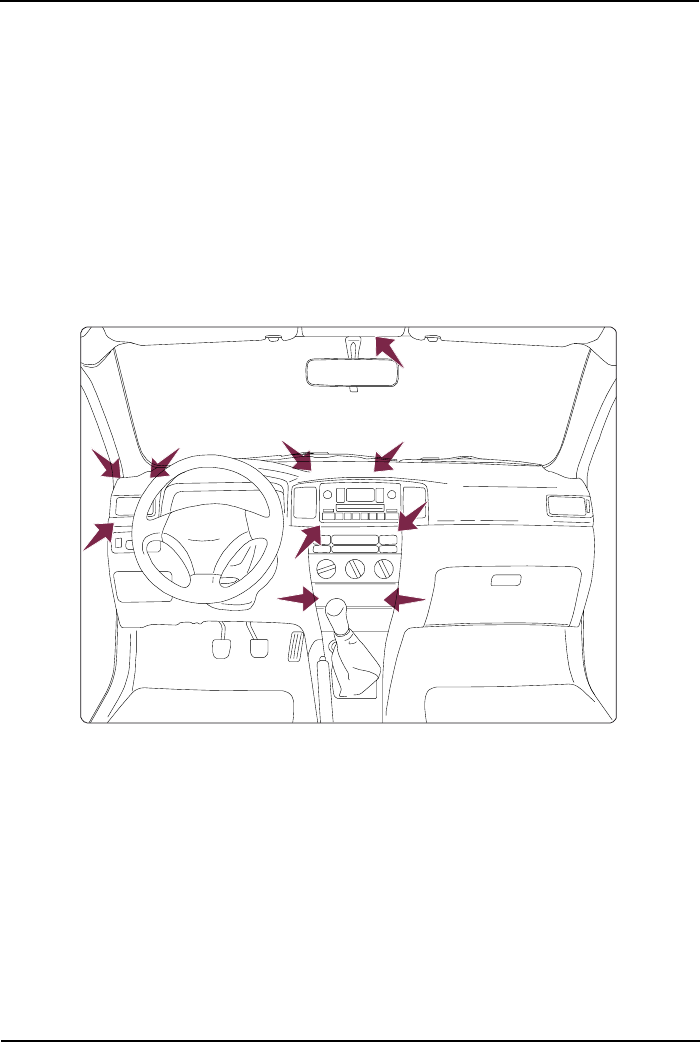
Selection of the installation location for the microphone
Suitable for the microphone:
•If voice sound is applied to the microphone unobstructed, the separation
distance between speaker and microphone should be approx. 35 cm
•On the A-pillar (between front windscreen and side window)
•Near the driver sun visor
•On the instrumentation panel
•On the steering column
-12-
Audio 2010
Installation
Unsuitable for the microphone:
•In loudspeaker proximity (less than 80 cm separation distance)
•Under the instrumentation panel
•In the air stream of the window or the fan
Selection of the installation location actuator/display
Suitable for the actuator:
•Central console between driver and passenger
•On the instrumentation panel, a location which can be easily reached by the
driver
Unsuitable for the actuator:
•Area of influence of the airbag
•Possible impact area of the head
•Outside of the range of the driver
-13-
Installation
Audio 2010
6. 3. Preparation for installation of the components
Dismantle radio
1. Remove the radio panel carefully, with help of a plastic wedge. In this case it
is to be ensured that no holding lugs or interlocks are broken off.
2. According to type of the radio, the fixing screws are to be loosened with a
screwdriver or a special extraction tool.
Remove the plug connector from the radio (radio stations stored by the customer
are deleted).
Note:
Before the removal of the radio, it is to be noted whether a radio code is possibly
required. If indicating instruments for the airbag are integrated into the panel, you
should not switch on the ignition plug connector after pulling the plug connector,
since this can result in an error report of the airbag. (e.g. VW Passat 3 C)
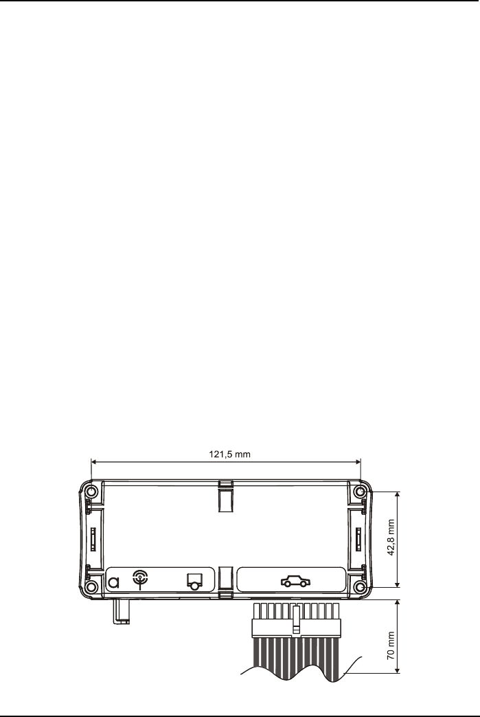
6. 4. Fastening of the electronic box
The electronic box offers two possibilities for fastening.
Possibility 1 - through installation with bolts:
First stipulate the fastening points. Note that approx. 70 mm space for the plug
connection remains. Now mark the screw positions.
Use four sheet metal screws with the corresponding spacing washers for the
fixing of the electronic box. We recommend a sheet metal screw with the mea-
surements „ST 2.9x25 DIN 7981“. These are optimally suitable for the fixing of
the electronic box. Pre-drill with a 2 mm drill.
-14-
Audio 2010
Installation
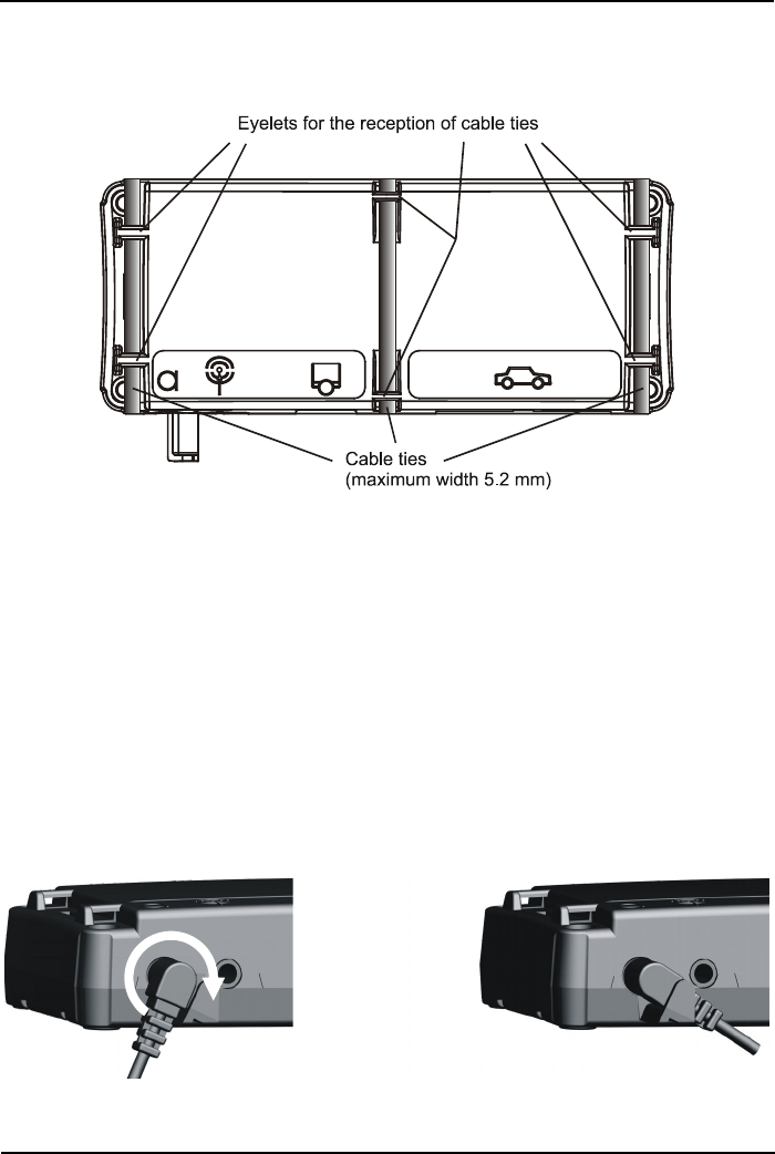
Possibility 2 - through installation with cable ties:
Eyelets, separately provided for the cable tie assemblies, are located on the elec-
tronic box.
6. 5. Mounting microphone
Note:
1. In order to guarantee effortless laying of the line, steering column paneling or
similar paneling parts must be removed as appropriate.
2. The microphone line is to be laid so that no further functions are impaired.
3. Route the jack plug of the microphone to the electronic box and plug in. The
connection and securing of the microphone jack plug is displayed in the follo-
wing illustration:
-15-
Installation
Audio 2010
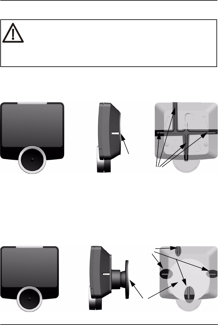
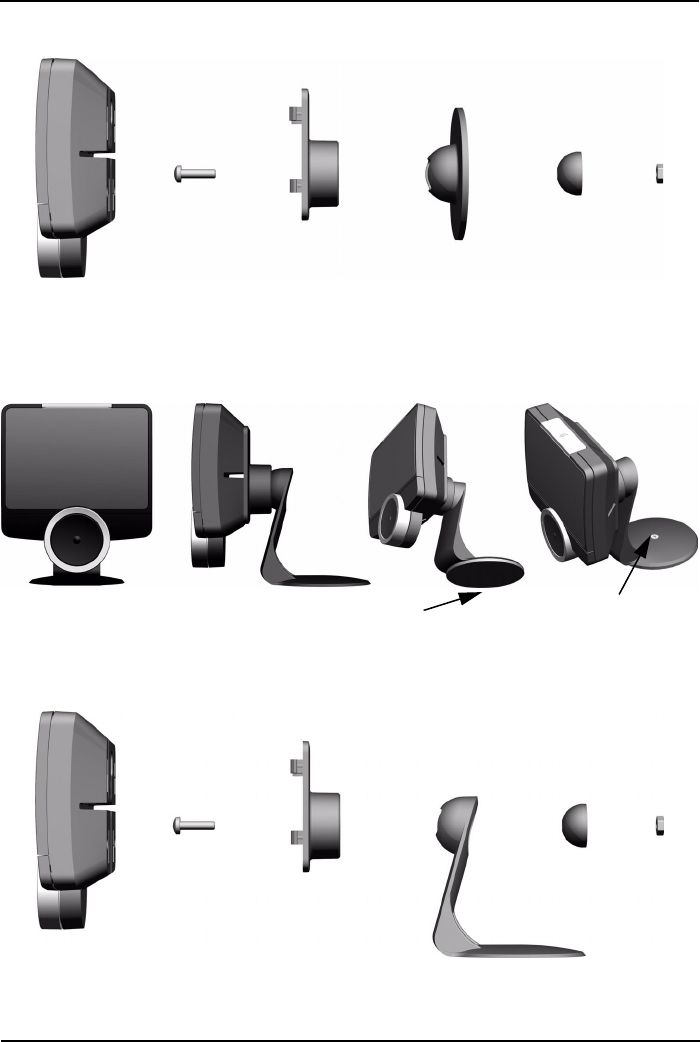
6. 6. Installation of the display and actuator
Variant 1
With the aid of an adhesive pad, the display can be attached directly on a flat sur-
face.
In order to structure the installation as inconspicuous as possible, the display has
4 possibilities of routing out the ribbon cable.
Variant 2
The display can also be attached with a ball adapter, which can also be indivi-
dually adjusted after fixing. The ball adapter is attached on a flat surface with the
aid of the adhesive pad.
Surfaces to be bonded must be free from grease and dust. Clean the
planned location with a suitable cleaning agent, such as e.g. spirit.
Employ these agents only if the plastics or painted wood surfaces do
not dissolve and are not self-lubricating. Unsuitable agents are e.g.
petroleum ether, acetone, turpentine, trichlorine ethylene and similar
cleaning agents!
Adhesive pad
Cable routing
Adhesive pad
Cable routing
-16-
Audio 2010
Installation
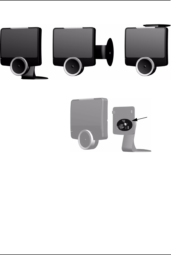
Assembly of the components (Variant 2)
Variant 3
If you wish to attach the display with the stand base, you can attach this with the
adhesive pad or with a bolt.
Installation of the retention foot (Variant 3)
Adhesive pad Fixing screw
-17-
Installation
Audio 2010
The utilization of the stand base offers you further possibilities for installation.
The display can also be mounted on its side or upside down.
With Variants 2 and 3 you
should latch the stand base
and ball adapter after align-
ment of the display by means
of the bolts.
After selection of a position for the actuator, blind covers and trim strips possibly
have to be dismantled in order to enable of the laying of the connecting leads
behind the instrument cluster.
Note:
The actuator should be in the field of vision of the driver, in order to ensure ease
of operation when driving. The actuator must not obstruct the driver.
Bolts for
latching
-18-
Audio 2010
Connection to the vehicle electronics
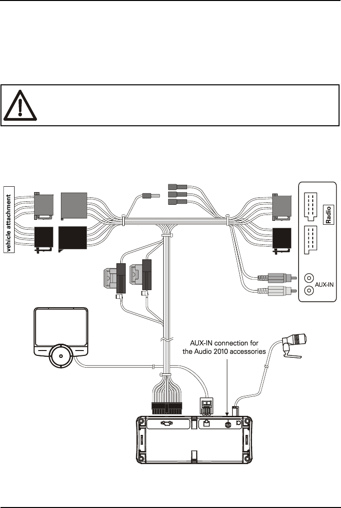
7. Connection to the vehicle electronics
using an adapter cable
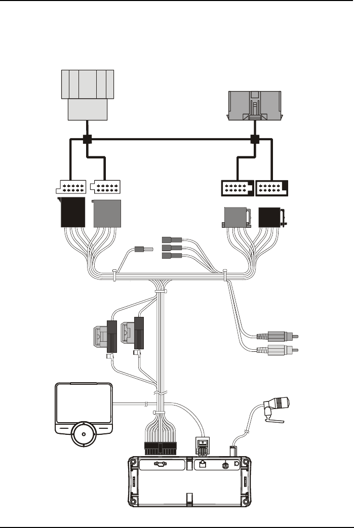
7. 1. Installation of the ISO connection cable
The installation of the cable can be seen in the illustration below.
Before the installation of the cable is begun, the battery must be dis-
connected! The minus pole must be disconnected from ground for
this purpose.
-19-
Connection to the vehicle electronics
Audio 2010
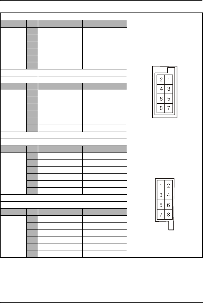
Socket contact housing Allocation of the power supply
Radio - type Pin Control color Function plug connection
Audi /
VW /
Grundig
1
2Mute
Allocation of the socket from behind
3(see Table)
4 blue Ignition (Ter.15)
7 red Battery + (Ter.30+)
8 brown Battery - (Ter.31)
Socket contact housing
Radio - type Pin Control color Function
Ford /
Mercedes /
Porsche /
Becker
1
2
3Mute
4 red Battery + (Ter.30+)
7 blue Ignition (Ter.15)
8 brown Battery - (Ter.31)
Socket contact housing
Radio - type Pin Control color Function
Blaupunkt
1Allocation of the connector from behind
2Mute
3
4 red Battery + (Ter.30+)
7 blue Ignition (Ter.15)
8 brown Battery - (Ter.31)
Socket contact housing
Radio - type Pin Control color Function
Philips
1Mute
2
3
4 red Battery + (Ter.30+)
7 blue Ignition (Ter.15)
8 brown Battery - (Ter.31)
-20-
Audio 2010
Connection to the vehicle electronics
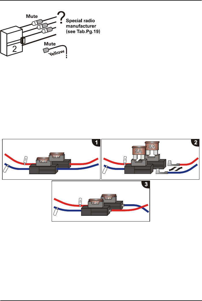
Checking the mute inputs
The mute inputs 1-3 can be seen in the
illustration. The yellow mute cable of
the Audio 2010 is connected to one of
these inputs. Please refer to the table
for which mute input is to be used.
The matching mute connection is
separated and connected with the yel-
low cable.
7. 2. Checking the installation
If the ISO connection cable has been connected correctly, the message
www.fwd-online.de is represented on the display with ignition switch-off. If this
message does not appear, then the ignition cable (blue) must be interchanged
with the voltage supply cable (red) (see Fig.).
red
blue
red
blue
red
blue
blue
blue
red
red
blue
red
-21-
Connection to the vehicle electronics
Audio 2010
7. 3. Installation with additional ISO(2Car) adapter
If your vehicle does not have an ISO plug connector, you have the possibility to
connect the handsfree system to the vehicle electronics using an ISO adapter.
(see Fig. below)
-22-
Audio 2010
Connection to the vehicle electronics
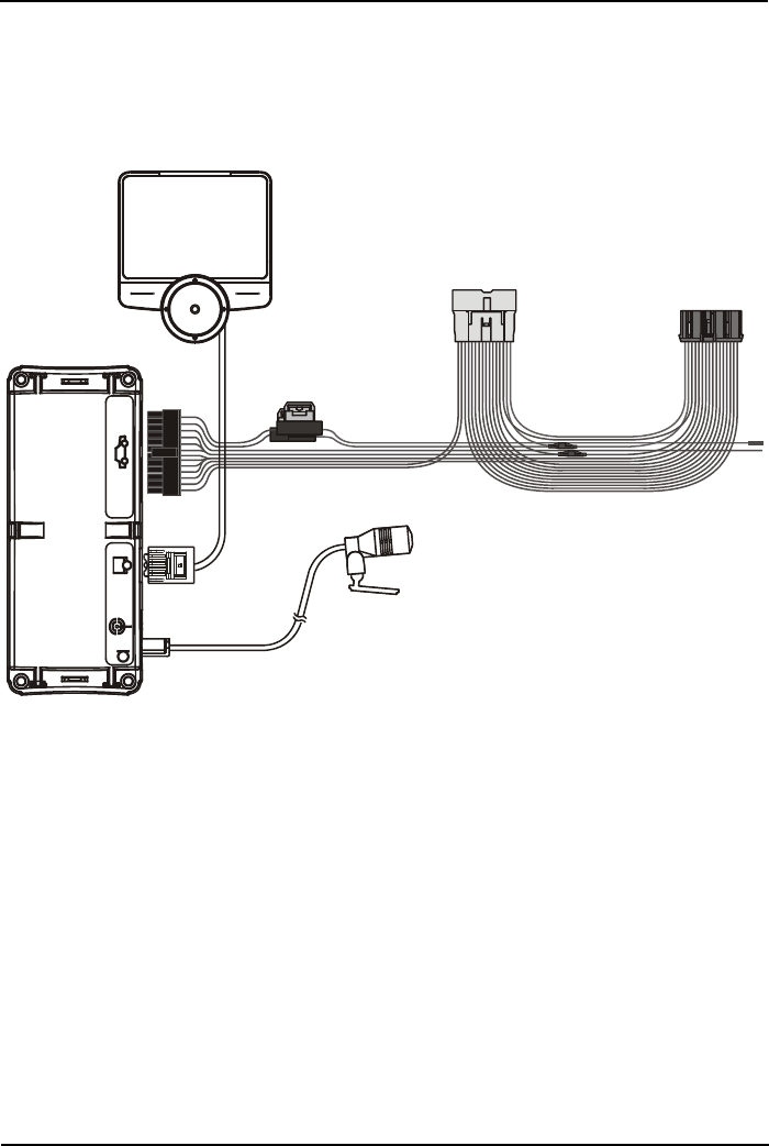
7. 4. Installation with the aid of a vehicle-specific
connecting cable
If a vehicle-specific cable is employed (also designated Audio2Car Cable), this is
connected as displayed in Fig.
*) Similar to illustration
*
-23-
Connection to the vehicle electronics
Audio 2010
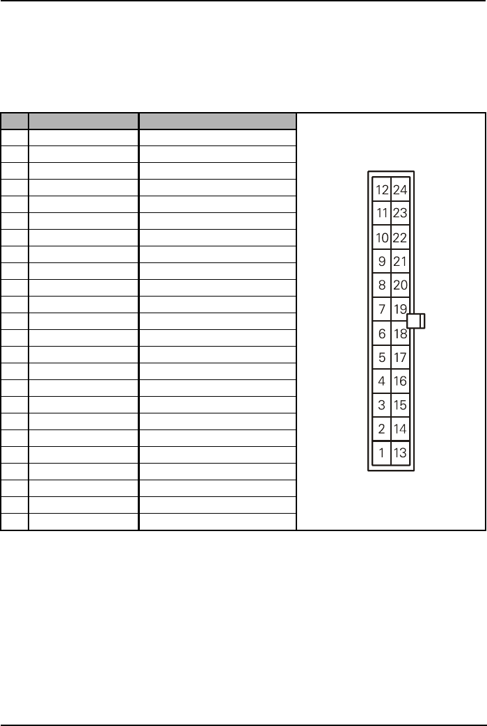
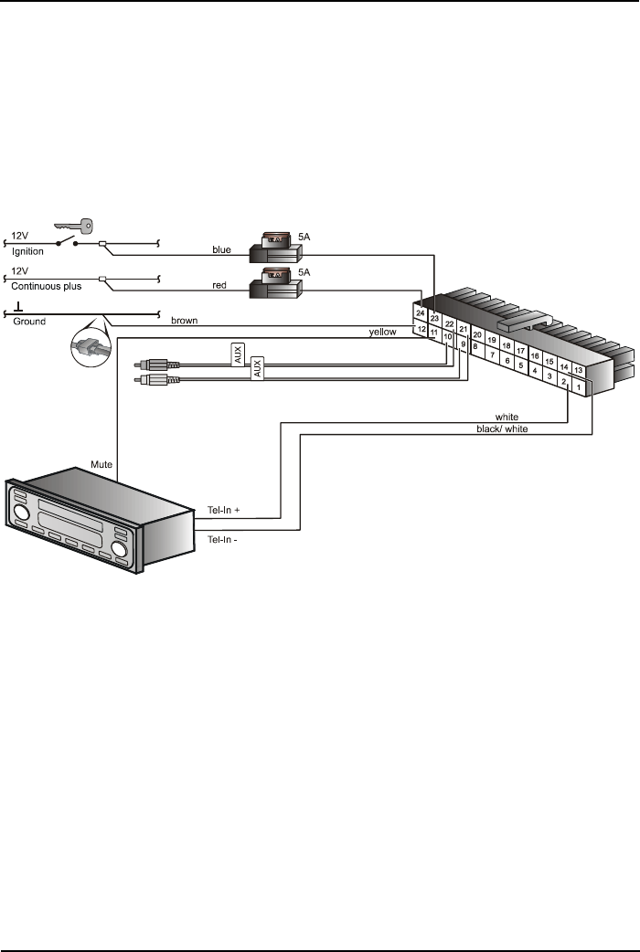
8. Connection to the vehicle electronics
by separate wiring of the lines
Electronic box connector pin assignment
Pin Color Function
1 yellow Loudspeaker RR+
2 white Loudspeaker RF+
3 green Loudspeaker LF+
4 orange Loudspeaker LR+
5 orange Radio LR+
6 green Radio LF+
7 white Radio RF+
8 yellow Radio RR+
9 red Line out R+
10 white Line out L+
11 yellow Mute
12 brown GND
13 yellow / black Loudspeaker RR-
14 white / black Loudspeaker RF-
15 green / black Loudspeaker LF-
16 orange / black Loudspeaker LR-
17 orange / black Radio LR-
18 green / black Radio LF-
19 white / black Radio RF-
20 yellow / black Radio RR-
21 black Line out R-
22 brown Line out L-
23 blue Ignition 12V
24 red Continuous plus 12V
-24-
Audio 2010
Connection to the vehicle electronics
8. 1. Reproduction over the phone connection of the
car radio
If your car radio has a phone connection (also often designated as „Tel-In“), then
you can connect the loudspeaker output of the electronic box directly with this,
according to the sketch (lines white, + and black/white, - of the adapter cable
set). This is the most convenient solution.
-25-
Connection to the vehicle electronics
Audio 2010
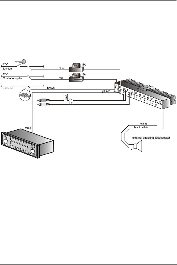
8. 2. Reproduction over an external loudspeaker
In the following cases, an external loudspeaker (4
Ω
, min. 5W) must be
employed:
•If loudspeakers of the car radio should not be employed
•If the output power of the loudspeaker channel exceeds 35 W (sine) and no
telephone connection to the car radio is provided
•If the car radio is operated with active boxes and no telephone connection to
the car radio is provided.
Feedback loops disturb the intelligibility. Place the external loudspeaker at a
distance of at least 80 cm from the microphone. For fixing the external loudspea-
ker, note the references of the respective manufacturer. The loudspeaker con-
trols can be connected to the white (Pin 2) and black/white (Pin 14) lines of the
connecting cable. Before this, the line is to be separated from the ISO plug con-
nector.
-26-
Audio 2010
Connection to the vehicle electronics
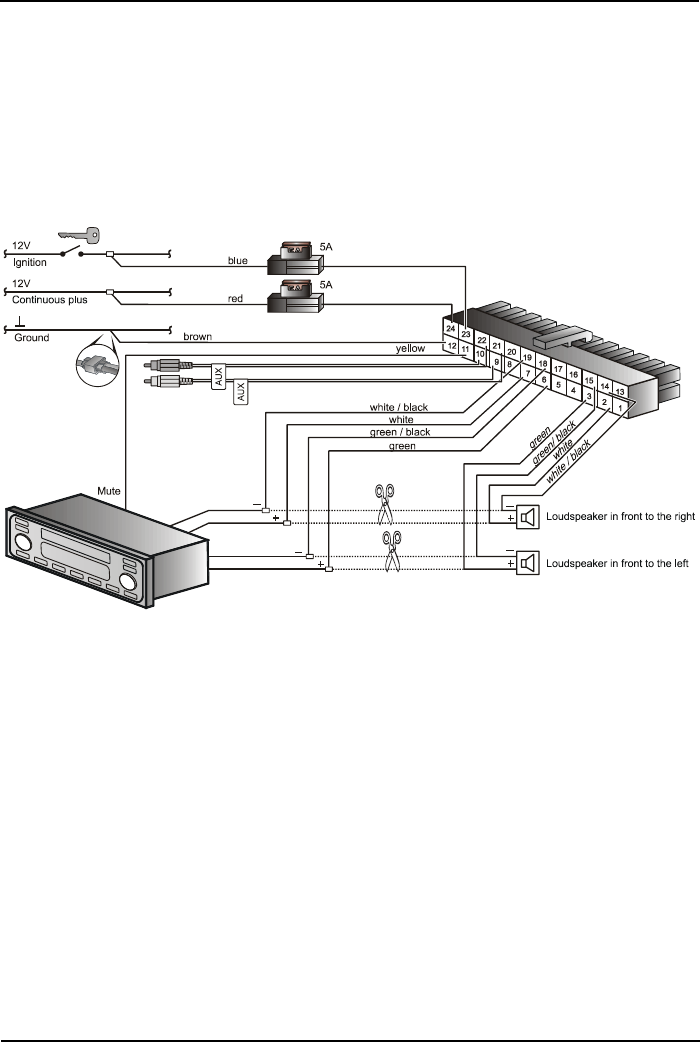
8. 3. Reproduction over the loudspeakers of the car
radio
If your car radio does not have a phone connection, you can connect the loud-
speaker output of the electronic box with the existing car loudspeakers, accord-
ing to the sketch.
It is recommended to use the front right loudspeaker, since here the feedback
loop risk is low, and the communication remains good. In this case, an auto-
matic switchover is implemented from radio to hands-free operation.

-27-
FAQ - Frequently Asked Questions
Audio 2010
9. FAQ - Frequently Asked Questions
Problem Cause Solution
Vehicle does not have
any ISO plug connec-
tors on the radio
Utilization of an ISO ad-
apter (see Section 7.3)
Utilization of a vehicle-
specific cable (see Sec-
tion 7.4)
Separate wiring system
of the individual lines
(see Section 8.1 - 8.3)
No Terminal 15 (ignition
plus) is on the radio
As a result of introduc-
tion of the CanBus sy-
stem, the ignition signal
is no longer necessary
on the radio with many
car manufacturers.
Utilization of a CanBus
adapter
Ignition identification
box (e.g. „Ignibox“)
Ignition contact is at
other locations in the ve-
hicle e.g.: an ignition si-
gnal could be applied:
- Fuse box
- Cigarette lighter
- Air-conditioning plant
Radio does not mute
No contact, or incorrect
contact, connected
Connect contact on the
radio.
(You can find informa-
tion on that in the direc-
tions of the radio)
In spite of connected
contact, no „mute“ of
the radio.
„Mute“ must be swit-
ched on in the setting-
adjustment menu of the
radio. (You can find infor-
mation on that in the di-
rections of the radio)

-28-
Audio 2010
FAQ - Frequently Asked Questions
On switching off the
ignition, the call is inter-
rupted.
Are the lines for conti-
nuous plus and ignition
plus interchanged on the
line circuit of the hands-
free system.
Connect lines correctly
(see Section 7.2)
Strong echo at the other
end of the call
Loudspeaker couples
into the microphone
branch
Increase separation di-
stance between micro-
phone and loudspeaker
Reduce loudspeaker vo-
lume
Call subscriber com-
plains about too low
communication volume
Microphone too low
Reduce separation di-
stance between micro-
phone and driver
Adapt the microphone
level in the settings
menu
-29-
Spare parts and accessories
Audio 2010
10. Spare parts and accessories
Spare parts:
➀
Electronic box
➁
Actuator with OLED display
➂
Adhesive pad
➃
Assembly set
➄
Microphone
➅
ISO connection cable
2
1
3
4
5
6
-30-
Audio 2010
Spare parts and accessories
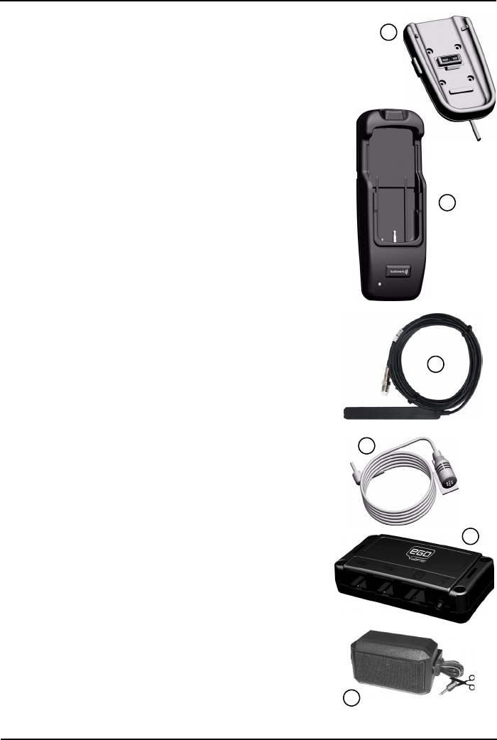
Accessories FWD:
➀
Base plate for charging holders
•secure hold of the charging holder
➁
Universal charging holder
•The charging holder* is the practical accessory
for Bluetooth® handsfree systems. It offers
secure retention and enables the charging of the
mobile telephone battery in the vehicle. Ideal for
high-mileage drivers and frequent telephone
users.
* Function only in combination with ➀
•intelligent electronic charger for the mobile
telephone
•secure retention of the mobile telephone in the
charging holder
•external antenna connection for excellent call
quality
➂
Stick-on antenna
•for the installation in combination with the base
plate, if external antenna is existing
➃
Gray microphone
•for installation in vehicles with bright interior
➄
idapter
•control of the iPod over the Audio 2010
•Battery charging of the iPod
➅
External additional loudspeaker
•Audio reproduction
1
2
3
4
5
6

-31-
Declaration of Conformity
Audio 2010
11. Declaration of Conformity
This device works with Bluetooth
®
radio technology. In some countries, this
device cannot be used or is allowed to a limited extent only. Please find out about
such restrictions and do not employ the device if you are not sure whether the
use is allowed or not in a certain country.
Bluetooth
®
is a brand of Bluetooth SIG, Inc.
Herewith Funkwerk Dabendorf GmbH
Märkische Straße
D-15806 Dabendorf
declares that the „Audio 2010“ Handsfree System
is in agreement with the basic requirements and the other relevant
specifications of Directive 1999/5/EC.
0681

Adress: Märkische Straße
D - 15806 Dabendorf
Phone: +49 3377 316 - 0
Fax: +49 3377 316 - 300
E-mail info@fwd-online.de
Web: www.fwd-online.de
Funkwerk Dabendorf GmbH