Montage 831200 Traxit 3 2G GPS Tracker User Manual TXL1G2 3 x
Montage Traxit 3 2G GPS Tracker TXL1G2 3 x
UserManual.wiki
>
Montage
>
831200 User Manual
User Manual
Navigation menu
Upload a User Manual
Namespaces
Wiki Guide
HTML
PDF
Info
Views
User Manual
Discussion / Help
Navigation
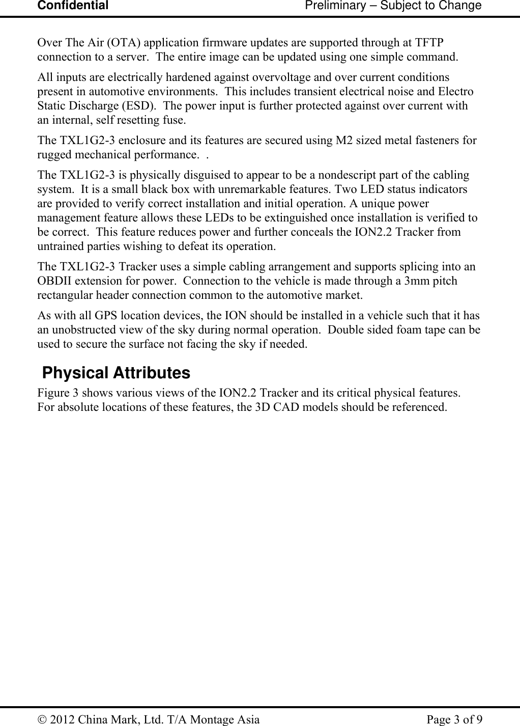
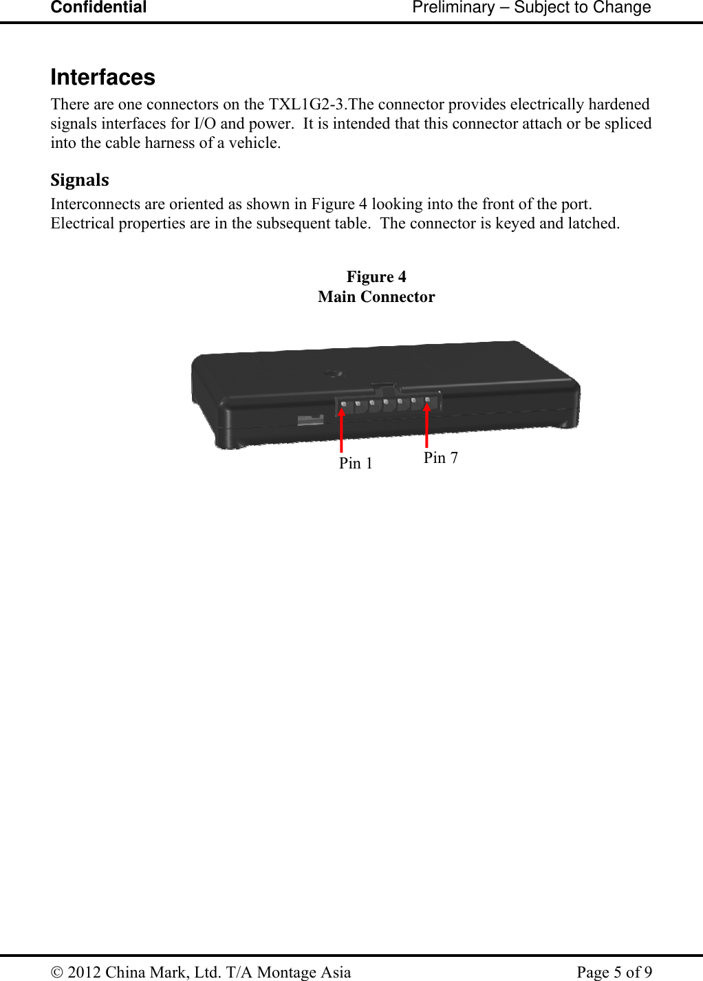
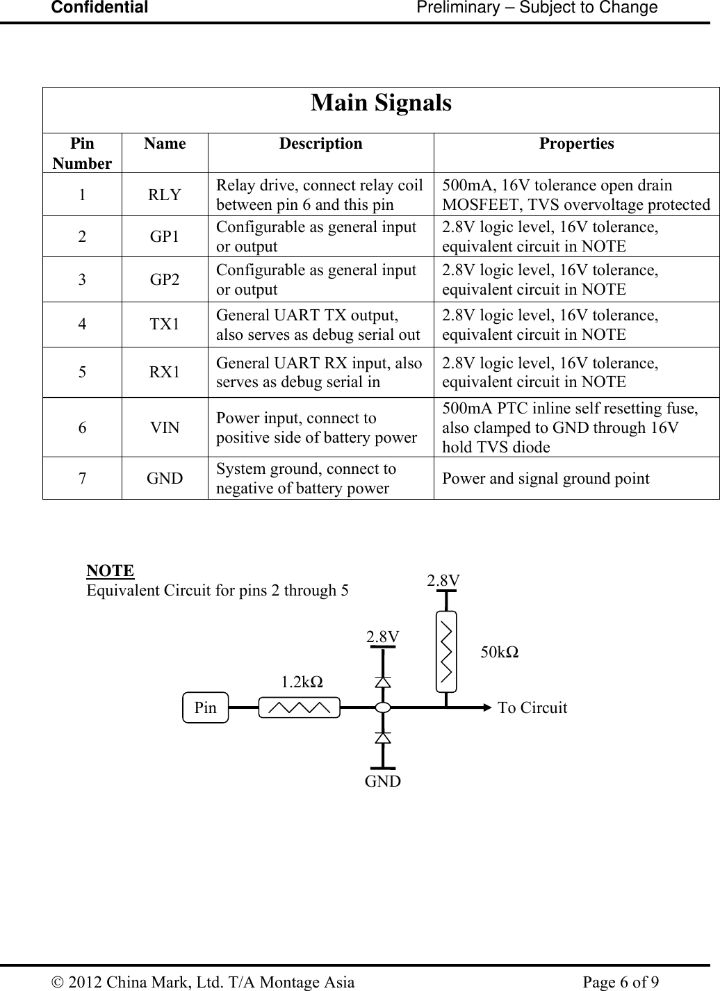
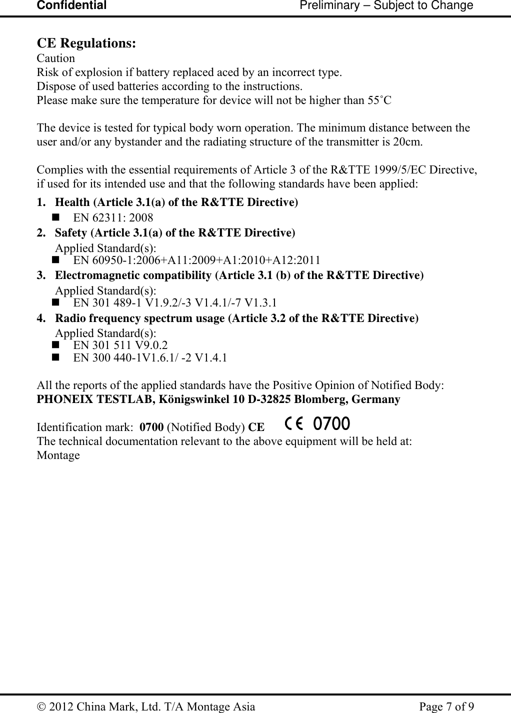
![Confidential Preliminary – Subject to Change 2012 China Mark, Ltd. T/A Montage Asia Page 4 of 9 Figure 3 TXL1G2-3 Physical Attributes AES/PC Plastic EnclosureLED Indicators Main Connector Units: Inches [mm] Sidecar Mounts M2 Fasteners (4 PL) Expansion Door M2 FastenerSIMTop Front Bottom BackTop Back](https://usermanual.wiki/Montage/831200/User-Guide-1857966-Page-4.png)