Moseley Associates 08MUD1F Digital Video Transmitter User Manual expedio manual
Moseley Associates Inc Digital Video Transmitter expedio manual
UserManual.wiki
>
Moseley Associates
>
08MUD1F User Manual
>
Manual
Contents
1.
Manual
2.
Revised Manual
Manual
Navigation menu
Upload a User Manual
Namespaces
Wiki Guide
HTML
PDF
Info
Views
User Manual
Discussion / Help
Navigation
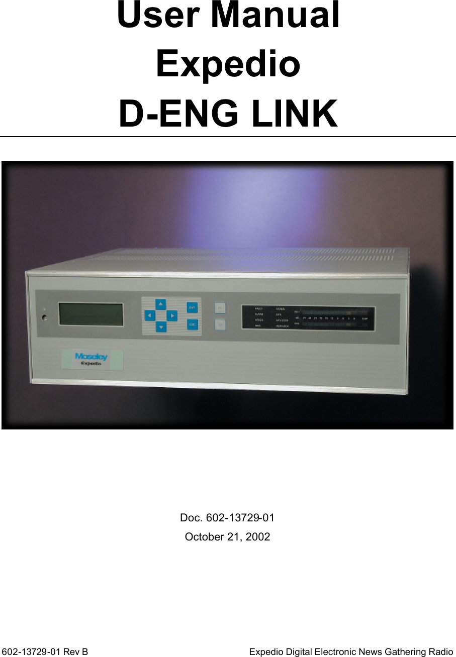
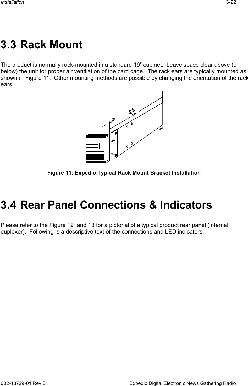
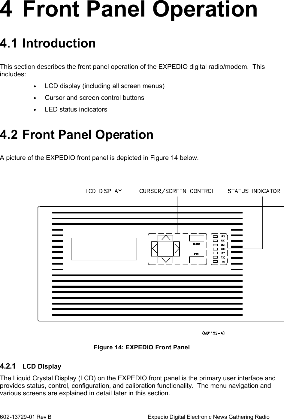
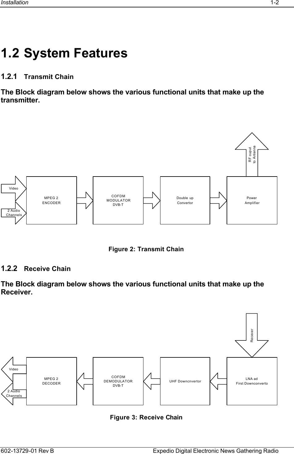
![602-13729-01 Rev B Expedio Digital Electronic News Gathering Radio 1 System Description 1.1 Introduction The digital system comprises of a Transmitter and a Receiver, whose output RF frequency is in the Band 1.9GHz to 2.9GHz. The RF band is approximately 300MHz. Transmitter is comprised of a MPEG2 Video Encoder which will take composite Video and digitize this and compressed, the output transport stream [DVB-TS] is then converted to DVB-ASI, which is then Modulated with COFDM (or any other digital modulators). The COFDM modulator is compliant to DVB-T non-hierarchical modes. This modulated signal is then converted to the appropriate with an IF of 480MHz thus providing the means to tune over a band at the RF signal. Receiver will down convert from the RF signal to an IF of 480MHz. This IF is then demodulated providing a DVB-TS. This data stream is then MPEG2 Video Decoded and provided as analogue Video output, together with the Audio channels. . Figure 1: Expedio Modular Open Architecture .](https://usermanual.wiki/Moseley-Associates/08MUD1F.Manual/User-Guide-290670-Page-5.png)
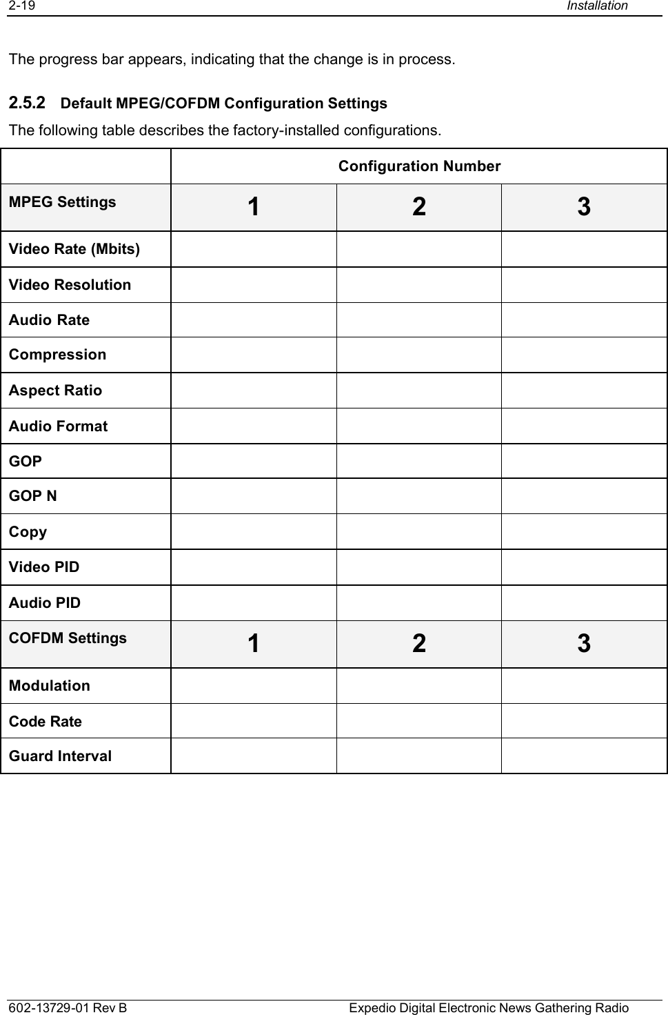
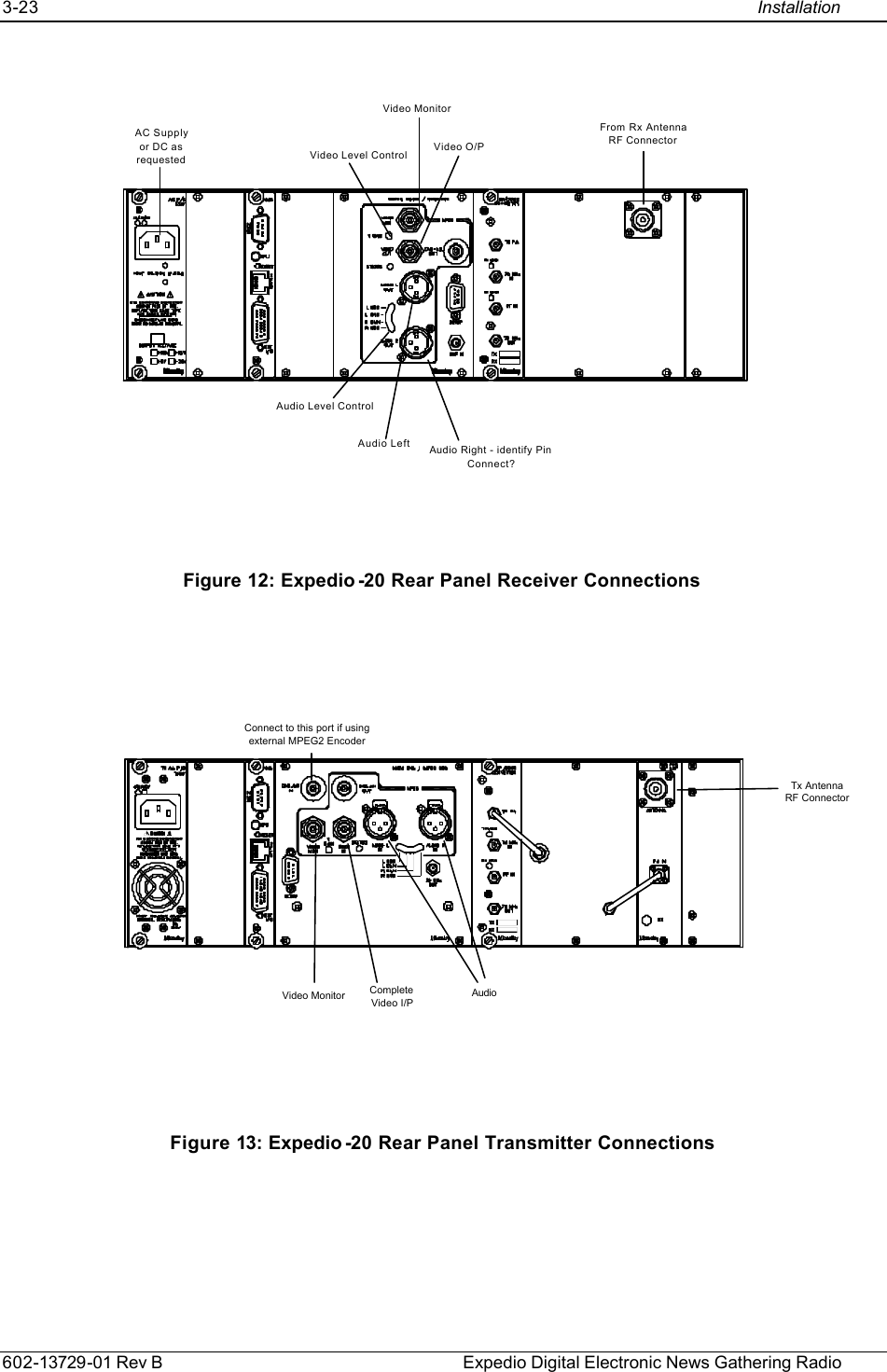
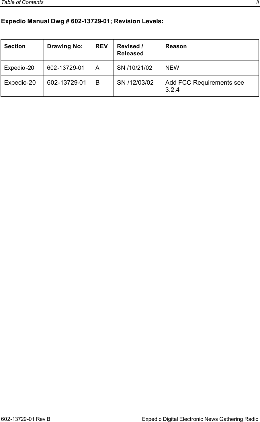
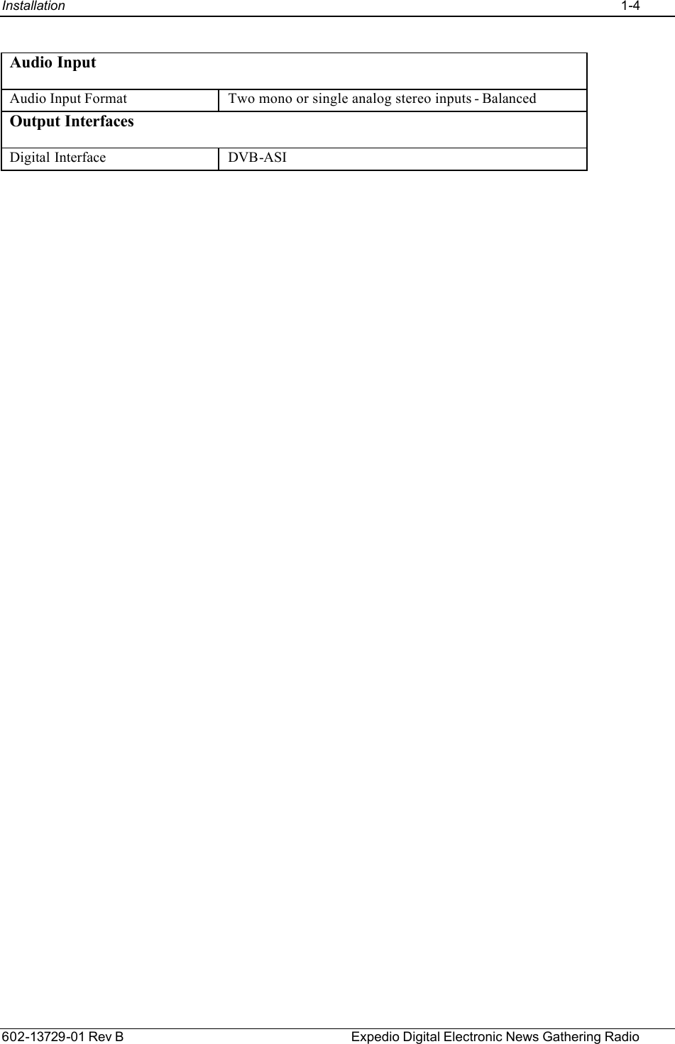
![1-3 Installation 602-13729-01 Rev B Expedio Digital Electronic News Gathering Radio 1.2.3 Video Encoder Video input is Composite video at 75ohms BNC, with a monitor port available. There are 2 Audio channels whose input are through the XLR connections. The data is encoded using advanced MPEG-2 encoding technology. The compressed data is formatted and transmitted using the DVB-ASI standard. The unit compresses the incoming video using an adaptive field/frame MPEG-2 Main Profile @ Main Level algorithm, achieving variable bit rate of 512 Kbps-12 Mbps. c] The Data Output that is DVB-SPI shall be converted to DVB-ASI with the data to be 188 byte only, the COFDM modulator will insert the Reed Solomon Encoding frames. Standard Compliance Video Encoding ISO/IEC 13818-2 (MPEG-2), 4:2:0 MP@ML, and MP@LL System Multiplexing ISO/IEC 13818-1 (MPEG-2). Generated Stream Types Video ES Video Elementary Stream. Audio ES Packetized Audio Elementary Stream. Video PES Packetized Video Elementary Stream. Program Program Stream. Transport Transport Stream. Video Encoder Video Input Format Analog: Composite NTSC (30 fps), Composite PAL(25 fps) Video Input Bit Resolution 9 bits. Preprocessor Programmable 2D (7x6) filter. Temporal and Spatial noise reduction. Bit Rates CBR and VBR, 512 Kbps to 12 Mbps. Bit Rate Resolution 1000 Hz Variable Frame Rate Programmable frame rate decimation (1 fps through 30/25 fps) support for low bit rate applications. Programmable Picture Resolution Horizontal: 720, 640, 544, 480, 360, 320, 160 Vertical : 112, 240, 480 (NTSC) 144, 288, 576 (PAL) Motion Estimation Horizontal: +/-100 H, Vertical: +/-34V. Same search area in P and B pictures, in both forward and backward searches. Half PEL accuracy. Aspect Ratio Square, 4:3, 16:9 Picture type I, P, B frame processing. GOP Structure I(M=0), IP(M=1), IPB(M=2), IPBB(M=3)](https://usermanual.wiki/Moseley-Associates/08MUD1F.Manual/User-Guide-290670-Page-7.png)
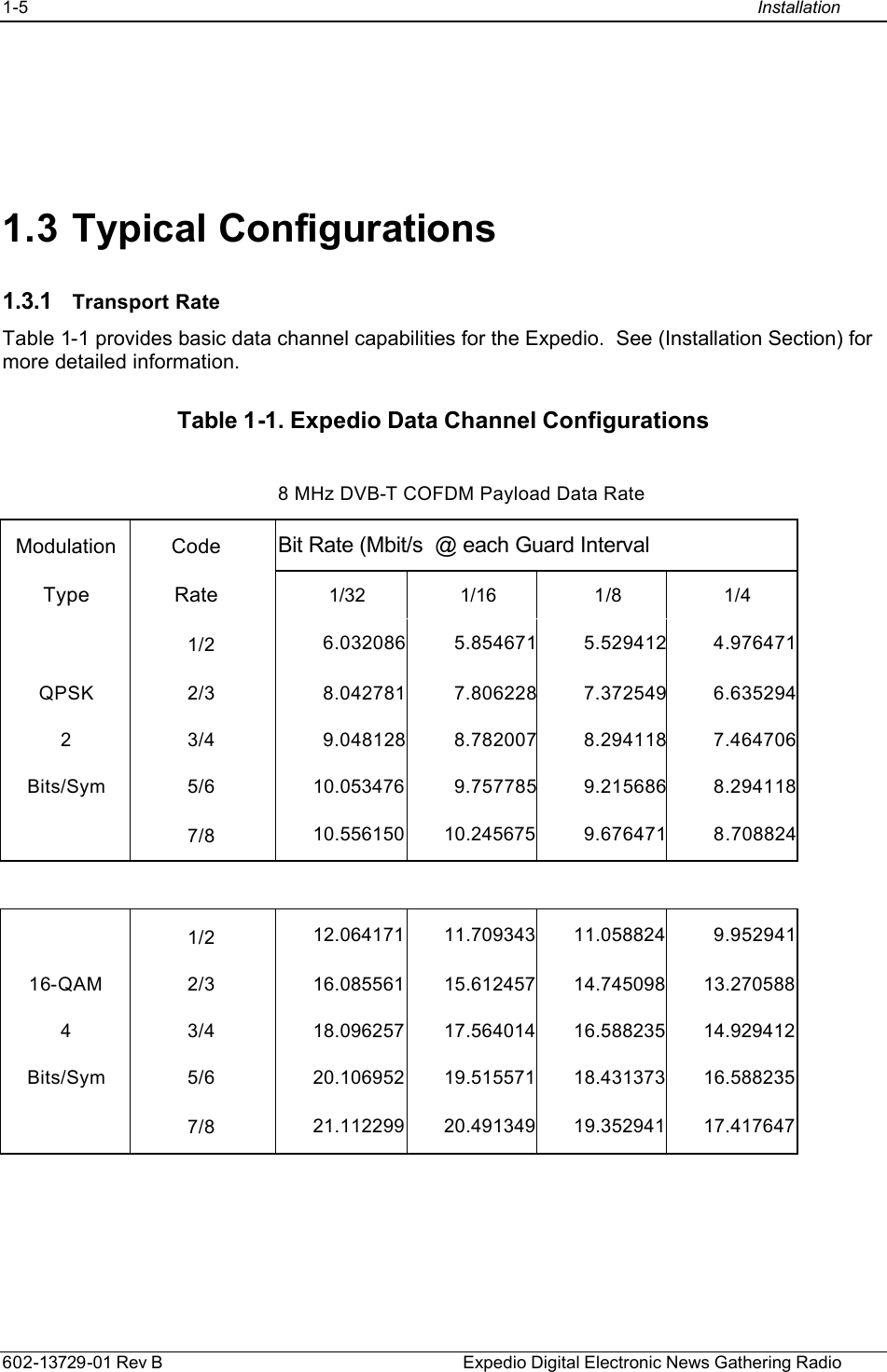
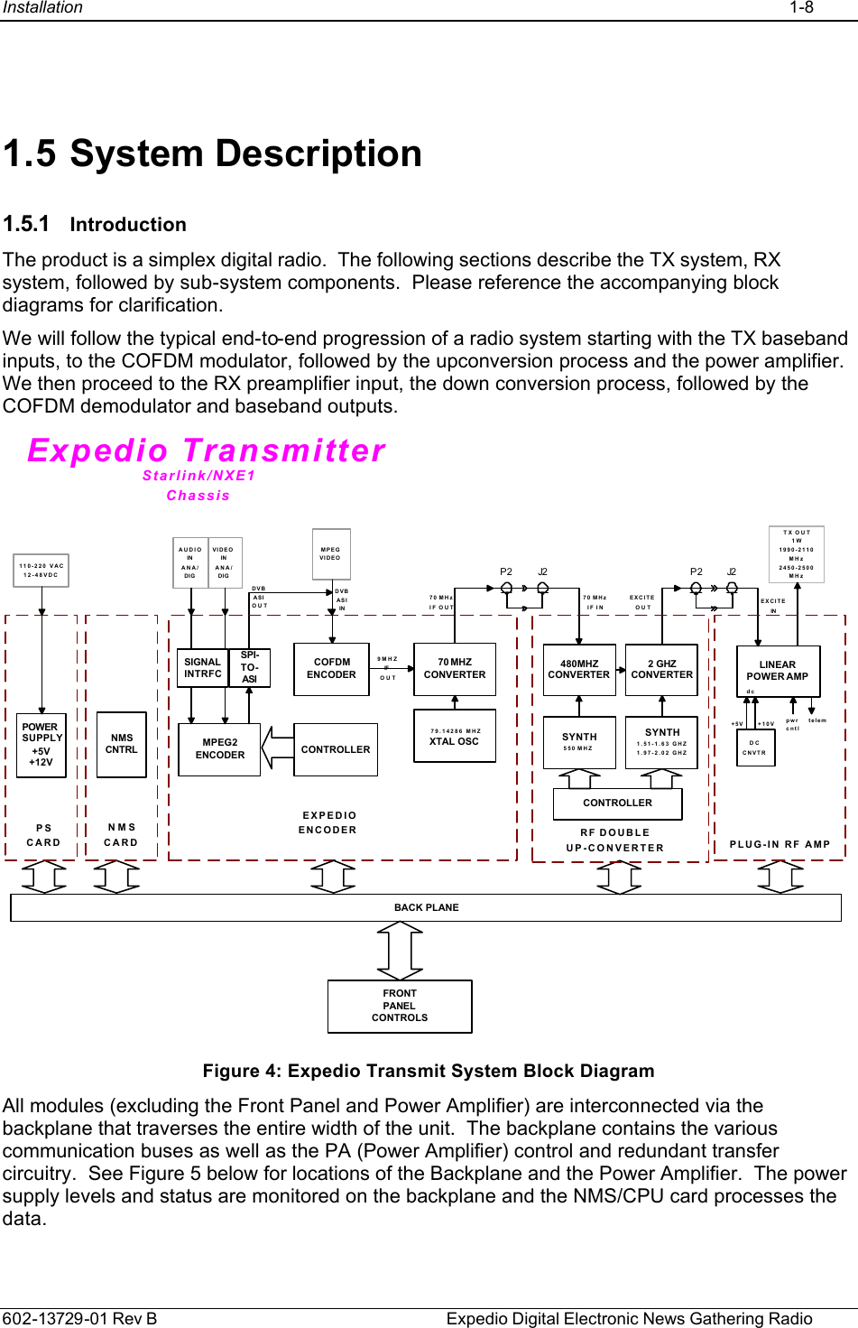
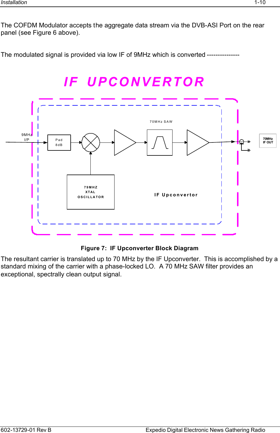
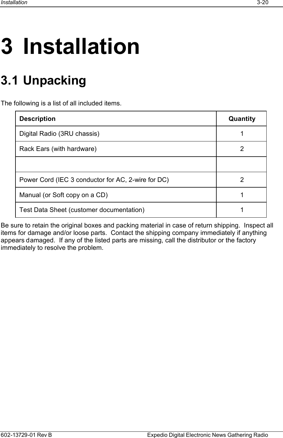
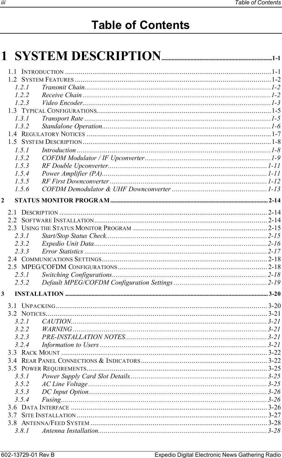
![1-9 Installation 602-13729-01 Rev B Expedio Digital Electronic News Gathering Radio Figure 5: Location of the EXPEDIO Backplane and Power Amplifier The NMS/CPU card incorporates microprocessor and FPGA logic to configure and monitor the overall operation of the system via front panel controls, LCD screen menus, status LEDs and the bar graph display. Module settings are loaded into the installed cards and power-up default settings are stored in non-volatile memory. LCD screen menu software is uploaded into memory, providing field upgrade capability. A Windows-based PC interface is available for connection at the rear panel DATA port. 1.5.2 COFDM Modulator / IF Upconverter ASI to SPIConvertorDVB-ASII/P FECReed SolomonInterleaverViterbiMappingModulationInverseFFT2KDACBP Filter [9MHz]&Gain control9MHzIFControlLinesControl from HitachiCOFDM MODULATOR Figure 6: COFDM Block Diagram The COFDM (Coded Orthogonal Frequency Division Multiplex) Modulator is the transmit portion of the card. The unit also houses the IF Upconverter. Backplane Digital Radio](https://usermanual.wiki/Moseley-Associates/08MUD1F.Manual/User-Guide-290670-Page-13.png)