MotorGuide FP02 Remote Control Transmitter User Manual
MotorGuide Remote Control Transmitter
User Manual

835 W. 41st Street
Tulsa, Oklahoma 74107
www.motorguide.com
© 2005, MotorGuide
FCC and IC Compliance Statement
FCC ID #MVUFP01, MVUFP02
IC ID 6094A-FP01, 6094A-FP02
This device complies with part 15 of the FCC Rules.
Operation is subject to the following two conditions:
1. This device may not cause harmful interference,
and
2. This device must accept any interference received,
including interference that may cause undesired
operation.
This device complies with FCC Rules. Changes or
modifications not expressly approved by MotorGuide
could void the user's authority to operate the
equipment.

Congratulations
… on your purchase of the MotorGuide Wireless Trolling Motor. This
motor has been designed, engineered, and manufactured to give you the
best possible dependability and exceptional performance for years of
enjoyment. These features offer an unrivaled fishing experience:
Durability
Oversized brushes for efficient and dependable power
Fully Remote Operation Integrated, Quick Release Mount
Modular Digital Electronics Three-year Limited Warranty
IMPORTANT!!
REGISTER YOUR
PRODUCT
The warranty registration card
(located inside the box) should be
completed and mailed to
MotorGuide to validate your
warranty.
WARRANTY CARD
REGISTRATION
IS INCLUDED IN THE BOX
AND IS SEPARATE FROM
THIS MANUAL.
PLEASE FILL OUT
IMMEDIATELY AND MAIL TO
VALIDATE YOUR
WARRANTY.
At MotorGuide, we’ve taken all the
victories, failures, blood, sweat,
tears, hours, days and years to
heart and built what are possibly
the best performing, most reliable
trolling motors ever.
It’s a result of re-engineering from
top to bottom, from our new digital
modules, to new switches and
props. Why? The reason is
simple. To give you the
advantage—and, in this case it’s a
digital advantage.
Because at MotorGuide, we
believe there are some things you
should Never Stop doing,
NEVER STOP LEARNING,
NEVER STOP IMPROVING,
AND NEVER EVER STOP
FISHING.

TABLE OF CONTENTS
GENERAL INFORMATION ....................................................................2
Safety DO’s and DON’Ts ...................................................................3
Operating Safety ................................................................................4
NOTES: ..................................................................................................5
FEATURES.............................................................................................6
Remote Capabilities ...........................................................................6
COMPONENTS......................................................................................7
Wireless Remote Foot-Pedal .............................................................7
Lower Unit ..........................................................................................7
Column...............................................................................................7
Top Housing.......................................................................................7
Cradle Lock™ Mount .........................................................................8
Battery Indicator .................................................................................8
INSTALLATION....................................................................................10
Mount Installation .............................................................................10
Wiring & Battery Information ............................................................13
Wire & Cable Routing ..................................................................13
Establishing a Common Ground..................................................14
Recommendations.......................................................................14
Activating the Foot-Pedal Electronic ID ...........................................17
Erasing the Receiver’s Memory .......................................................17
MOTOR & MOUNT OPERATION ........................................................18
General Information
Features & Components
Installation
Motor & Mount Operation
Adjusting the Motor Depth and Deploying the Motor .......................18
Stowing the Motor ............................................................................19
Operating the Foot-Pedal.................................................................20

MAINTENANCE ...................................................................................21
Foot-Pedal Battery Replacement.....................................................21
Care & Cleaning Instructions ...........................................................22
Customer Responsibilities................................................................22
Battery..........................................................................................22
Freezing Temperature Storage....................................................23
Installing or Replacing the Propeller ................................................23
TROUBLESHOOTING .........................................................................25
Frequently Asked Questions............................................................25
MOTORGUIDE ACCESSORIES 28
Troubleshooting & Accessories
Warranty
Maintenance
MOTORGUIDE LIMITED THREE-YEAR WARRANTY .......................29

MOTORGUIDE WIRELESS
90-MM5997 For Questions, Contact Consumer Affairs at #1-920-929-5040 1
© 2005, MotorGuide www.motorguide.com
NOTES:
____________________________________________________
____________________________________________________
____________________________________________________
____________________________________________________
____________________________________________________
____________________________________________________
____________________________________________________
____________________________________________________
____________________________________________________
____________________________________________________
____________________________________________________
____________________________________________________
____________________________________________________
____________________________________________________
____________________________________________________
____________________________________________________

MOTORGUIDE WIRELESS
90-MM5997 For Questions, Contact Consumer Affairs at #1-920-929-5040 2
© 2005, MotorGuide www.motorguide.com
GENERAL INFORMATION
Please read and retain this manual. The information within describes the proper
procedures for safely installing, operating and maintaining your motor.
!
Failure to follow a safety WARNING can result in bodily injury.
WARNING
CAUTION
Failure to observe CAUTION instructions can result in failure or damage to the
product or equipment.
INFORMATION
The information symbol signifies important information about your trolling
motor.
NOTE
The Note symbol signifies a statement calling attention to general information
about your trolling motor.
The description and specifications contained herein were in effect at the time
this manual was approved for printing. MotorGuide, whose policy is one of
continual improvement, reserves the right to discontinue models at any time, to
change specifications, designs, and methods of procedure without notice and
without incurring obligation.
Safety and operating information that is practiced along with good common
sense can help prevent personal injury and product damage.
If the motor automatically throttles back, it indicates something may
be wrong with the motor and it should be taken in for service.
CAUTION
A slight voltage drain occurs when the trolling motor is continually
connected to the battery for extended periods of time. To prevent
battery drain when not in use for an extended period, disconnect the
trolling motor from the power source.
CAUTION

MOTORGUIDE WIRELESS
90-MM5997 For Questions, Contact Consumer Affairs at #1-920-929-5040 3
© 2005, MotorGuide www.motorguide.com
Disconnect the trolling motor from the battery(s) before charging.
CAUTION
How to Use This Manual
Review the following information carefully. These notices will alert you to
potential dangers and important information.
The observance of WARNINGS and CAUTIONS alone does not eliminate the
possibility of personal injury or product damage. Your close attention to the
performance of recommended service procedures and the practice of
responsible personal safety are major accident prevention measures.
Safety DO’s and DON’Ts
!Do not allow children to operate the trolling motor without adult
supervision.
!Do not modify the unit in any way or add accessories other than approved
MotorGuide accessories.
!Do not power-wash your trolling motor.
!Do disconnect the power from the motor when replacing the prop,
removing debris around the prop, charging batteries, putting your boat on a
trailer or when the motor is not in use.
!Do make sure the foot-pedal is secured and the motor is securely locked
into the stowed position when using a gasoline motor to move to another
location, or when putting your boat on a trailer.
Do secure loose items on your boat before traveling at high speeds across
the water.
!
Do always connect to the battery through a power plug or a power switch
which can be easily disconnected. Never “hardwire” the motor directly to
the batteries. Use the recommended circuit breaker to protect the wires.
!

MOTORGUIDE WIRELESS
90-MM5997 For Questions, Contact Consumer Affairs at #1-920-929-5040 4
© 2005, MotorGuide www.motorguide.com
!Circuit Protection – MotorGuide recommends installing a 50 amp
manual-reset circuit breaker and power switch in line with the trolling motor
positive leads within (1.8 m) 72 inches of the battery(s). To order a circuit
breaker kit, contact your local Service Dealer, request kit number MM5870.
See the “Accessories” section of this manual for more information.
Operating Safety
1. Observe all boating safety guidelines as outlined by the US Coast Guard
or by the governing agency for your area. Guidelines are typically posted
at your local marina.
2. Do not operate the trolling motor while under the influence of alcohol or
while taking medication that may impair your judgment.
3. Be aware of the possibility of unseen, underwater obstacles when
navigating in shallow water, keep the boat speed down to a safe level.
4. When navigating near shore, watch for overhead obstacles such as tree
limbs and floating dock tie-down cables.
5. When steering your motor, pay attention to your speed to determine a safe
rate at which to turn without throwing passengers off balance.
6. Before turning the prop on, observe the direction the motor is pointing to
avoid abrupt turns that could throw passengers off balance.
7. When the power is off but the motor is plugged in, keep your hands and
feet away from the propeller.
8. Always unplug the battery when performing motor maintenance.
9. To avoid a trip hazard, route all cables and wiring neatly and out of the
way.
10. Disconnect the trolling motor from the battery when it’s not in use.

MOTORGUIDE WIRELESS
90-MM5997 For Questions, Contact Consumer Affairs at #1-920-929-5040 5
© 2005, MotorGuide www.motorguide.com
NOTES:
____________________________________________________
____________________________________________________
____________________________________________________
____________________________________________________
____________________________________________________
____________________________________________________
____________________________________________________
____________________________________________________
____________________________________________________
____________________________________________________
____________________________________________________
____________________________________________________
____________________________________________________
____________________________________________________
____________________________________________________
____________________________________________________
MOTORGUIDE WIRELESS
90-MM5997 For Questions, Contact Consumer Affairs at #1-920-929-5040 6
© 2005, MotorGuide www.motorguide.com
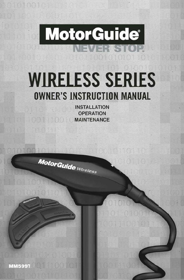
Lower Unit
FEATURES
Composite Column
Top Housing
Cradle Lock Mount
Wireless Foot-Pedal
Remote Capabilities
The MotorGuide Wireless uses a remote foot-pedal with the receiver built into
the trolling motor mount. These remote capabilities work with the Digital
Remote Control (DRC) product and up to four remotes (including the foot-
pedal) can be used with one motor. See the “Accessories” section of this
manual for more information.
!
Modifications to this remote device not expressly approved by the
manufacturer may invalidate the user’s right to operate this equipment.
WARNING
MOTORGUIDE WIRELESS
90-MM5997 For Questions, Contact Consumer Affairs at #1-920-929-5040 7
© 2005, MotorGuide www.motorguide.com
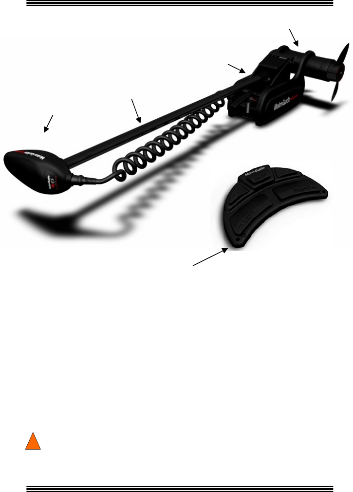
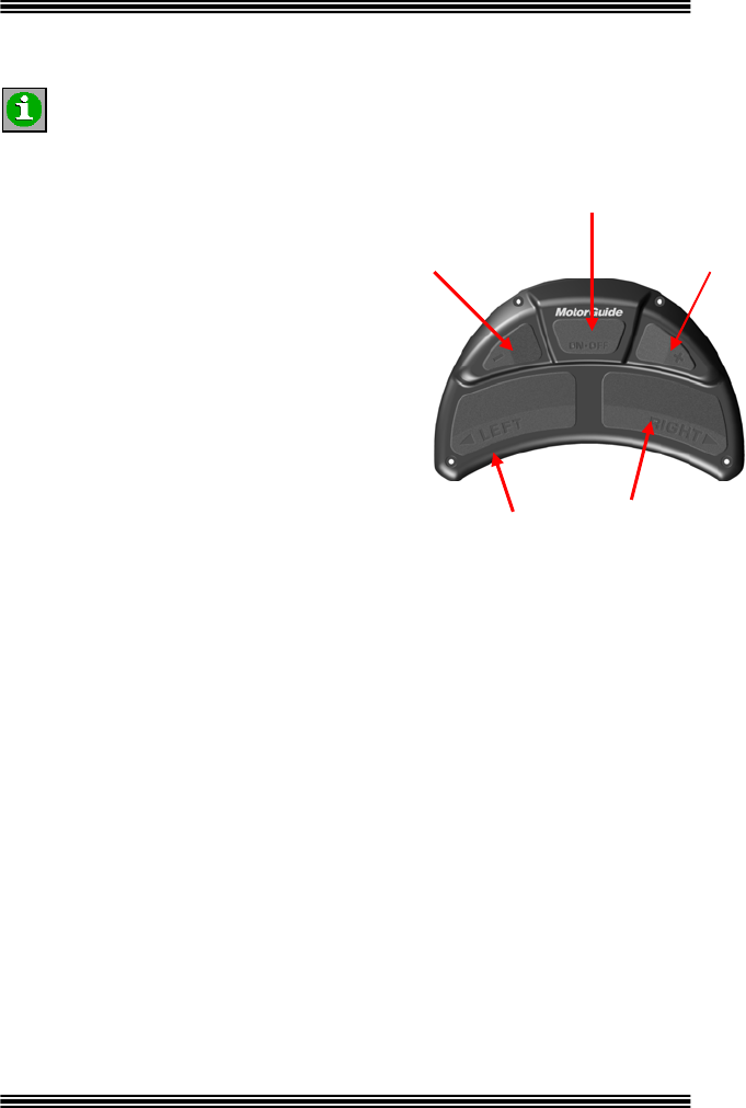
COMPONENTS On/Off Button
Wireless Remote Foot-Pedal Slower Button Faster Button
The remote foot-pedal functions include
the off/on, right/left and faster/slower
motor operations. The anti-slip design
makes motor operation easy for the angler
wearing large boots. The battery used in
the foot-pedal is long-life, inexpensive and
replacement is easy.
Left Button Right Button
Lower Unit
The lower unit is available in a 12 or 24
volt variable speed motor. The oversized
brushes increase battery life and extend
trolling time.
Column
The MotorGuide Wireless composite shaft
is exceptionally strong, and flexible. The
shaft comes in 48, 54 and 60 inch lengths.
Top Housing
The sleek top housing design
indicates, at-a-glance, the
direction of the motor.
Additionally, no electrical
boards are located in the top
housing and it attaches to the
shaft with a single through bolt.
The rock-solid connection
between the top housing and
cable serves as an ergonomic
handle.
MOTORGUIDE WIRELESS
90-MM5997 For Questions, Contact Consumer Affairs at #1-920-929-5040 8
© 2005, MotorGuide www.motorguide.com
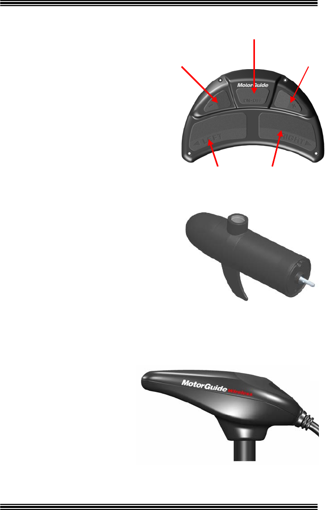
Prop
The MotorGuide Wireless uses the 3½ inch two blade
Power Prop.
Cradle Lock™ Mount
The rock solid design of the MotorGuide
Wireless mount has a quick-release
mounting plate and an easy access
lever for trouble-free stowing and
deploying the motor. The mount also
features a cradle that protects the motor
during rough-water runs.
Battery Indicator
The MotorGuide Wireless is equipped with a
battery charge indicator. The push button gauge
provides the angler an accurate reading of the
remaining battery charge. Battery charge readings
include:
Good
Fair
Low and
Recharge.
Test the battery with the motor off.
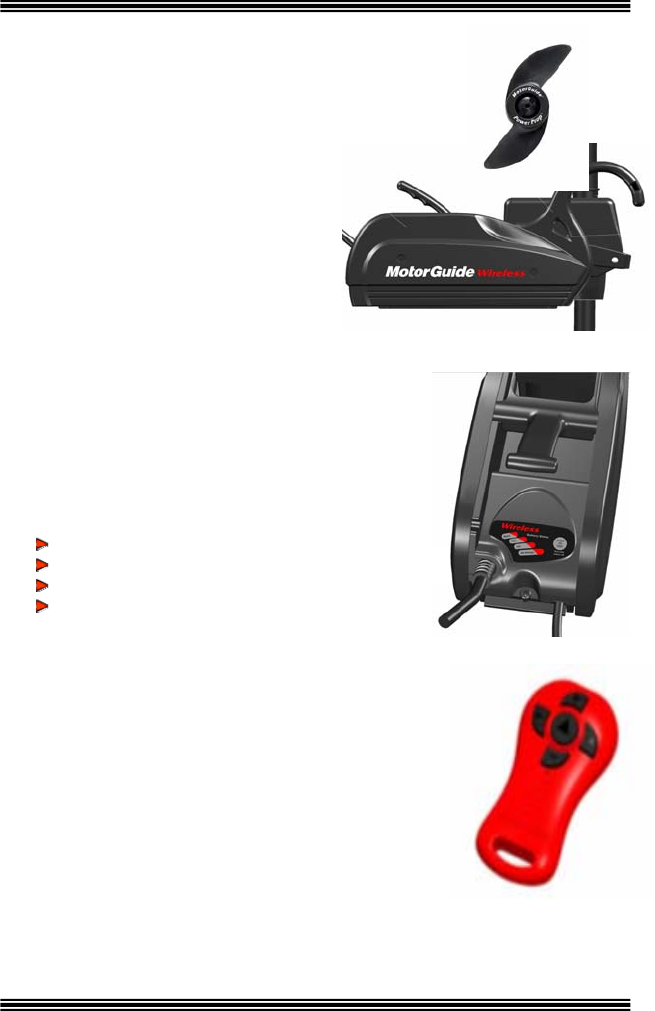
Digital Remote Control – Optional Accessory
Fingertip control is available with MotorGuide’s
optional Digital Remote Control (DRC) wireless
handheld. With the added value of a built-in receiver,
you are now free to move about the deck. Mix and
match up to four DRC handhelds or Wireless Foot-
pedals in any combination. Perfect for tournament
situations and/or tough bites that require teamwork,
precise boat control and accurate bait presentations.

MOTORGUIDE WIRELESS
90-MM5997 For Questions, Contact Consumer Affairs at #1-920-929-5040 9
© 2005, MotorGuide www.motorguide.com
NOTES:
____________________________________________________
____________________________________________________
____________________________________________________
____________________________________________________
____________________________________________________
____________________________________________________
____________________________________________________
____________________________________________________
____________________________________________________
____________________________________________________
____________________________________________________
____________________________________________________
____________________________________________________
____________________________________________________
____________________________________________________
____________________________________________________
MOTORGUIDE WIRELESS
90-MM5997 For Questions, Contact Consumer Affairs at #1-920-929-5040 10
© 2005, MotorGuide www.motorguide.com
INSTALLATION
Mount Installation
It is recommended that two people install the motor and mount.
Mount Base Plate on Boat Deck
Do not connect the motor to a power source until the motor and mount
are fully installed on the boat.
!WARNING
The tools required for the installation are:
1) Drill with (8 mm) 5/16 inch drill bit
2) #3 Phillips head screw driver
3) 1/2 inch open end wrench
1) Carefully select the area on the deck as close to the
centerline as possible to install the mount. Choose an
area where the mount will provide ample clearance from
the bow of the boat for all of the motor positions
including the run and stow positions. A 1 to 21/2 inch
clearance is needed between the shaft and the bow of
the boat. Ensure the forward mounting screws are
placed in a location on the deck where there is
enough room to install the screws and washers
without penetrating the hull.
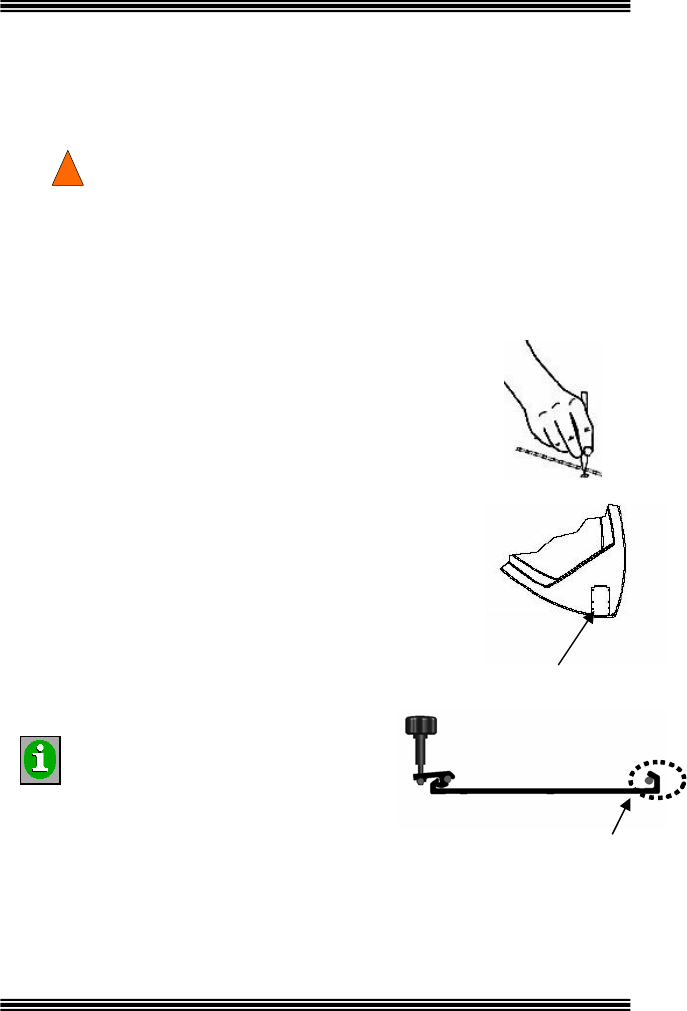
2) Remove the mount base plate from the mount
installation kit and place it on the surface of the boat
deck where it is to be mounted; use the mount plate
as a template to mark the location for drilling
the mount holes.
Side View of Mount Base Plate
The end of the mount base plate
with the large hook flange must be
positioned forward on the bow of
the boat.
INFORMATION
Position Large Flange
Hook Forward on Boat
3) Drill mounting holes with a (8 mm) 5/16 inch drill bit and then clear the holes
of any debris. On fiberglass boats, chamfer the holes to help reduce the
possibility of the fiberglass cracking.
MOTORGUIDE WIRELESS
90-MM5997 For Questions, Contact Consumer Affairs at #1-920-929-5040 11
© 2005, MotorGuide www.motorguide.com
4) Place the mount base plate on the boat deck aligning
the holes on the plate to the holes on the deck. Install
the four (4) stainless steel mounting bolts through
each of the mounting holes.
5) Install the four (4) stainless steel washers and nuts on
the bottom side of the deck and tighten securely.
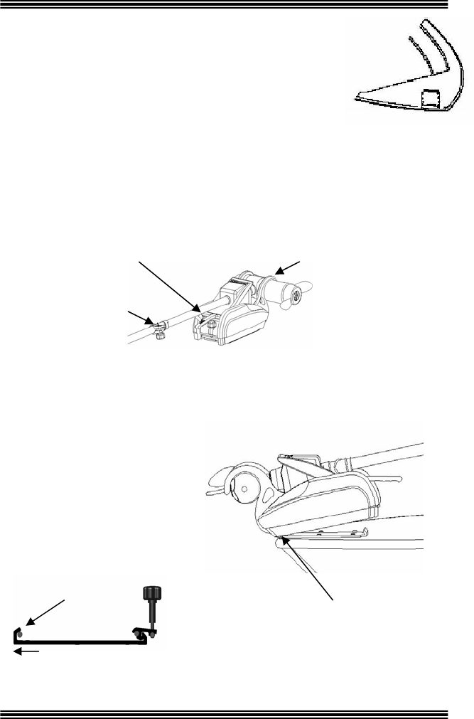
6) Remove the packaging material, in the box, from around the trolling motor.
7) Lift the motor and mount out of the box, turn the mount upright and and lay
it on a flat surface. Loosen the mount locking knob, located at the back of
the mount housing, until it can pivot approximately 25 degrees.
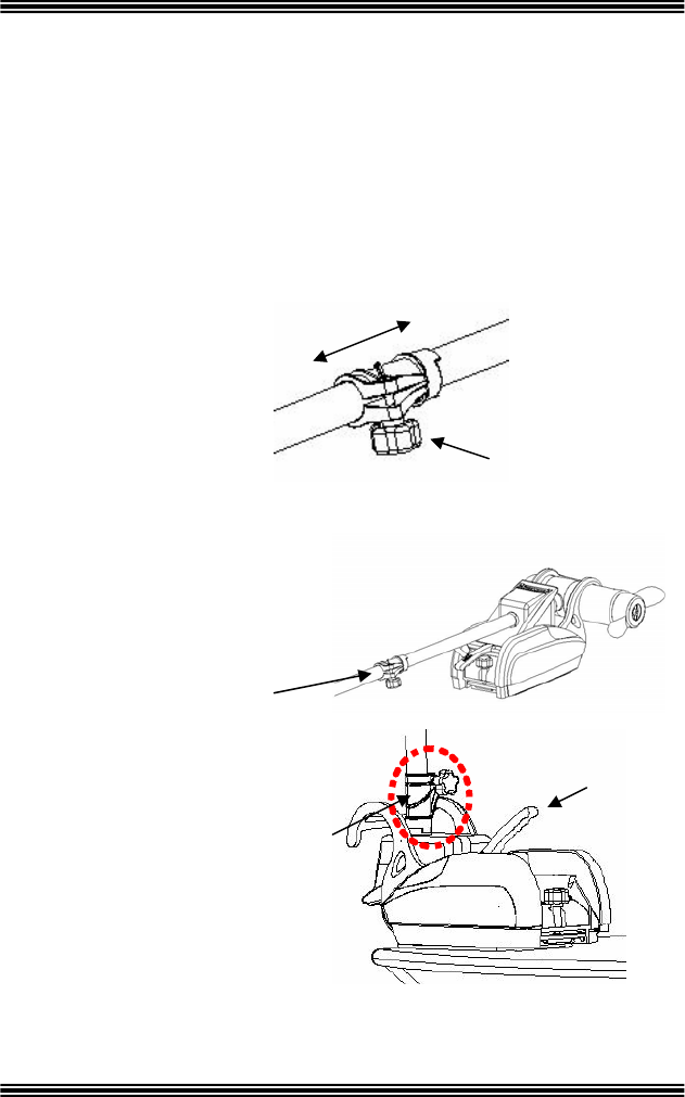
8) The motor is shipped with the
lower unit and mount in the stowed position, but the lower unit must be
placed into the locking cradle before proceeding. Pull up on the release
handle to unlock the transmission. Slide and pivot the lower unit as
needed to snap the lower unit inside the locking cradle.
Mount Locking
Knob
Lower Unit in Stowed
Position; Lower Unit
inside Cradle
Depth Collar
9) Lift the motor and mount and
place it over the mount base
plate. The end of the mount
housing with the lower unit
cradle and lower unit is
placed forward over the
mount base plate. Guide the
end of the mount with the
lower unit at
an
approximate 10o
downward angle
over the base plate until the pivot pin on
the underside of the mount fits into the
large flange hook on the base plate.
Lower Unit Cradle
Placed Forward over
Mount Base
Front of Base Plate
Large Flange Hook &
Pivot Pin
MOTORGUIDE WIRELESS
90-MM5997 For Questions, Contact Consumer Affairs at #1-920-929-5040 12
© 2005, MotorGuide www.motorguide.com
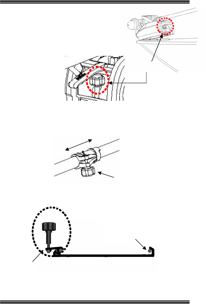
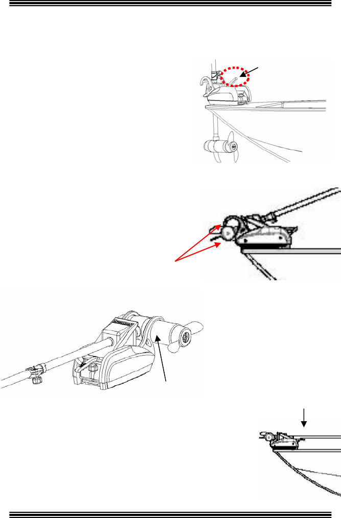
10) Sit the back of the mount housing over the
back of the mount base. Press down on
the back of the mount base and turn the
mount locking knob just enough to engage
the cam locking mechanism and secure
the mount onto the base plate.
Complete tightening
the cam locking
mechanism in step
12 below.
Mount Locking Knob
11) Position the depth collar on the shaft so that the lower unit will not strike
any obstacles (boat trailer, ground, etc.) when the motor is deployed and
then deploy the motor to the run position (see Motor & Mount Operation,
Deploying the Motor for complete instructions on deploying the motor).
Slide Depth Collar
Up or Down Shaft
Depth Collar
Knob Handle
12) Deploy the motor into the run position and then tighten the lock completely
by turning the mount lock knob.
Large Flange Hook
Cam Locking
Mechanism
Pivot Pin on Underside of
Mount Housing Fits Snuggly
under Large Flange Hook on
Mount Base
Side View of Mount Base Plate

MOTORGUIDE WIRELESS
90-MM5997 For Questions, Contact Consumer Affairs at #1-920-929-5040 13
© 2005, MotorGuide www.motorguide.com
For storage and security purposes the MotorGuide Wireless Cradle Lock™
mount makes it easy to completely remove and reinstall the mount and motor.
When the mount and motor are removed from the boat, a snap-on Wireless
Mounting Plate Cover (see the Accessories section of this manual for order
information) is available to protect the mounting plate.
Wiring & Battery Information
Batteries contain sulfuric acid which can cause severe burns. Avoid
contact with skin, eyes, and clothing. The battery also produces
hydrogen and oxygen gasses when being charged. This explosive gas
is released through the battery vents and may form an explosive
atmosphere around the battery for several hours after it has been
charged. Electrical arcing or flames can ignite the gas and cause an
explosion which may shatter the battery and could cause blindness or
other serious personal and property damage. Refer to your battery
manufacturer’s guidelines for charging instructions.
!WARNING
Be sure all switches are in the OFF position before connecting the
motor to the batteries. Electrical arcing near the battery could ignite
gas vapors causing an explosion.
!WARNING
Avoid serious injury or death from a possible fire caused by a direct
short; do not jump-start an outboard motor using the trolling motor
battery/batteries.
Wire & Cable Routing
!WARNING
Route trolling motor wires on the opposite side of the boat from other
miscellaneous boat wiring (bow light wiring, spot light wiring, etc.).
Transducer installation should be installed according to the manufacturer’s
specifications. To avoid interference, cables should be routed separately
from the trolling motor cables.

MOTORGUIDE WIRELESS
90-MM5997 For Questions, Contact Consumer Affairs at #1-920-929-5040 14
© 2005, MotorGuide www.motorguide.com
Important: Do not route a transducer cable down the trolling motor
power cord. Route the transducer cable down the side of the mount,
then into the bow console. Provide enough excess sonar cable to
allow the motor to make three (3) complete 360 turns.
Electronics, depth finders in particular, should be connected directly to the
main engine or an accessory battery. Do no connect your electronics to
the trolling motor battery.
Establishing a Common Ground
MotorGuide recommends isolating the trolling motor battery/batteries from the
main engine battery.
Electrolysis Issues – Using the engine starting battery as a source of power
for any trolling motor may cause electrolysis on metallic parts.
9 If you have followed the battery wiring and installation instructions in
this manual and your boat continues to have electrolysis issues, you
will need to separate the trolling motor from any other boat electronics.
9 Remove the engine starting battery from the wiring configuration of the
boat and isolate the power circuit for your trolling motor.
Establish a Common Ground: Common ground means the ground for
the main engine accessories and your trolling motor are connected to the
same negative ground terminal.
Not having a common ground can cause severe corrosion or electrolysis.
If left unchecked, damage may be caused to your trolling motor and boat.
Establishing a common ground connection will allow increased sensitivity
and improve detail on a sonar display.
Recommendations
Battery Type – The recommended battery is a 12-volt Deep Cycle battery.
Circuit Protection – MotorGuide recommends installing a 50 amp
manual-reset circuit breaker in line with the trolling motor positive leads
within (1.8 m) 72 inches of the battery(s). To order a circuit breaker kit,
contact your local Service Dealer, request kit number MM5870 or a 50
amp circuit breaker and a power switch.
Wire Size – For optimum performance, MotorGuide recommends the use
MOTORGUIDE WIRELESS
90-MM5997 For Questions, Contact Consumer Affairs at #1-920-929-5040 15
© 2005, MotorGuide www.motorguide.com
of six (6) gauge (13 mm) wires if extending the existing wire beyond the
standard battery cable supplied with the product.
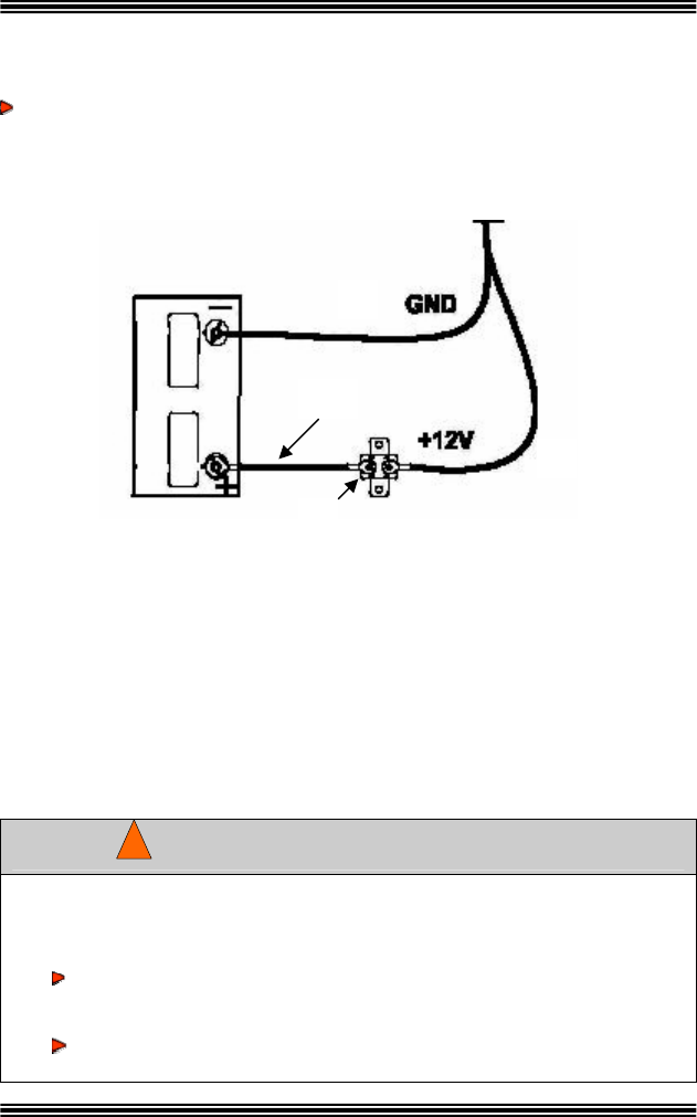
Bow Plugs – MotorGuide recommends the use of a quality plug designed
12 Volt Battery Hook-up
) Blac ) Jumper Wire
To trolling r
ower ctions
onnect the red battery lead from the power cable to the battery positive (+) -)
for marine applications.
A Dk battery lead (-)
B) Red battery lead (+)
C) 50 amp circuit E)
Breaker and a p motor conne
switch
C
post and the black battery lead from the power cable to the battery negative (
post. Install a 50 amp circuit breaker and a power switch in line with the
positive lead as shown in C above. (See the “Assessories” section in this
manual for the circuit breaker and power switch part number.)
O
WARNING
!
A
E
B
C
D
b when connecting the motor to the serve installation guidelines
batteries. When in doubt, consult a professional at your nearest
dealer.
Always connect to the battery through a power plug which can
be easily disconnected or through an easily accessible power
switch. Never “hardwire” the motor directly to the batteries.
Always use the recommended circuit breaker to protect the
wires.
MOTORGUIDE WIRELESS
90-MM5997 For Questions, Contact Consumer Affairs at #1-920-929-5040 16
© 2005, MotorGuide www.motorguide.com
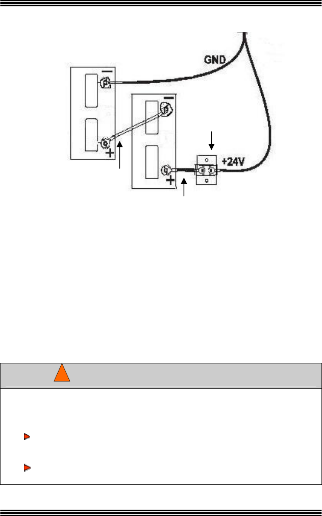
24 V B
A) Battery A E) Red battery leads (+)
B) Battery B F) 50 amp circuit breaker and a power
C) To trolling motor connections switch
D) Black battery leads (-) G) Jumper wires
Connect the black battery lead from the power cable to the negative (-) post on
battery A and the red lead from the power cable o the positive (+) post on
battery B. Connect a jumper wire between the negative (-) post of battery B
and the positive (+) post of battery A. Install a 50 amp circuit breaker in line
with the positive lead to battery B as shown above. (See the “Assessories”
section in this manual for the circuit breaker and power switch part number.)
olt attery Hook-up
Observe installation guidelines when connecting the motor to the
batteries. When in doubt, consult a professional at your nearest
dealer.
Always connect to the battery through a power plug which can
be easily disconnected or through an easily accessible power
switch. Never “hardwire” the motor directly to the batteries.
Always use the recommended circuit breaker to protect the
wires.
WARNING
!
B
A
C
D
E
G
G
F

MOTORGUIDE WIRELESS
90-MM5997 For Questions, Contact Consumer Affairs at #1-920-929-5040 17
© 2005, MotorGuide www.motorguide.com
Activa
ach foot-pedal has a unique electronic ID number. Up to four electronic ID
umbers (Digital Remote Control units and foot-pedals) can be stored by
our receiver. For your foot-pedal to respond to your commands only and not
ose of other boaters, you must activate the electronic ID number into your
ceiver. Follow the instructions below (one time only) to activate each new
mote control device:
1. Power the motor up - within 10 seconds, pre ld the “+” and “-“
buttons on the foot-pedal simultaneously
2. Listen for a long beep
3. The receiver has now learned and stored the electronic ID number of
the foot-pedal.
you are activating multiple remote control devices (up to four devices
mo ated) t motor d back on
ati each remote c
o erase all electronic ID numbers stored in the receiver’s memory:
ting the Foot-Pedal Electronic ID
E
n/or
y
th
re
re
ss and ho
If NOTE
can be accom d he must be powered off an
between activ ng ontrol device.
Erasing the Receiver’s Memory
T
1. Power-up the motor
2. Within 10 seconds, press and hold the “Left”, “Right”, “+” and “-“
buttons on the foot-pedal simultaneously
3. Listen for a long beep indicating the receiver has erased all stored
electronic ID numbers
MOTORGUIDE WIRELESS
90-MM5997 For Questions, Contact Consumer Affairs at #1-920-929-5040 18
© 2005, MotorGuide www.motorguide.com
Depth Collar
Knob Handle
Slide Depth Collar
Up or Down Shaft
MOTOR & MOUNT OPERATION
, turn the depth collar handle to tighten. Also, be
position.
3. Hold
the
motor
by the shaft or the top
housing and raise it into a
vertical position. Lower
the motor until the depth
collar rests on top of the mount housing collar. The motor is ready to
connect to the power source.
Adjusting the Motor Depth and Deploying the Motor
1. Loosen the depth collar by turning the knob handle. Slide the depth
collar up or down the shaft to a position that will allow the lower unit to
be submerged at least 12 inches (30cm) below the water surface
when the motor is fully deployed. When the depth collar is in the
desired location
cautious that the depth of the motor is deep enough to prevent the
lower unit from striking obstacles that could damage the skeg or prop.
2. Pull up on the release
handle and then raise the
motor out of the stow
Depth Collar Resting
on Mount
Release Handle
Motor in Stowed Position
MOTORGUIDE WIRELESS
90-MM5997 For Questions, Contact Consumer Affairs at #1-920-929-5040 19
© 2005, MotorGuide www.motorguide.com
Stowing the Motor
olding the shaft or top housing,
2. wate
lower
cradl
the
the
can be
4. o lock the cradle and
You will hear a click
lease handle are
1. Pull up the release handle and then, h
lift the motor up.
Release Handle
While lifting the motor out of the
r, rotate the shaft until the
unit is aligned with the locking
e.
3. Continue to pull
lower unit up to
mount until the
lower unit
snapped into the
cradle.
Push down on the column t
to lock the release handle.
when the lower unit and re
locked into position.
Lower Unit Locked in Push Down on the Column to
lock the Release Handle
Lower Unit Align
Locking Cradle ed with
Cradle
MOTORGUIDE WIRELESS
90-MM5997 For Questions, Contact Consumer Affairs at #1-920-929-5040 20
© 2005, MotorGuide www.motorguide.com
On/Off Button
Faster Button Slower Button
Left Button Right Button
Ope i
nsure the foot-pedal electronic ID has been the “Installation”
ection of this manual for instructions.
. Prop On/Off
Turn the prop on or off by pressing the
center button and it will alternate
between on and off. The “on” condition is
indicated by a short beep while “off” is
indicated by a long beep.
. Steering: Pr ns to steer the boat. Each
button press steers the motor left or right one tep; holding down a button
of the selected arrow.
rol the t
sound each time the + or – buttons are pushed. Holdi
will rapidly speed-up or slow-down the motor until it re
maximum speed; once at the limit, the receiver will no
you press a button.
rat ng the Foot-Pedal
E
INFORMATION
activated. See
s
1
2ess the left or right arrow butto
s
will rapidly steer the motor in the direction
3. Speed: Use the + and – buttons to cont mo or speed, a beep will
ng the button down
aches minimum or
longer beep when
MOTORGUIDE WIRELESS
90-MM5997 For Questions, Contact Consumer Affairs at #1-920-929-5040 21
© 2005, MotorGuide www.motorguide.com
MAINTENANCE
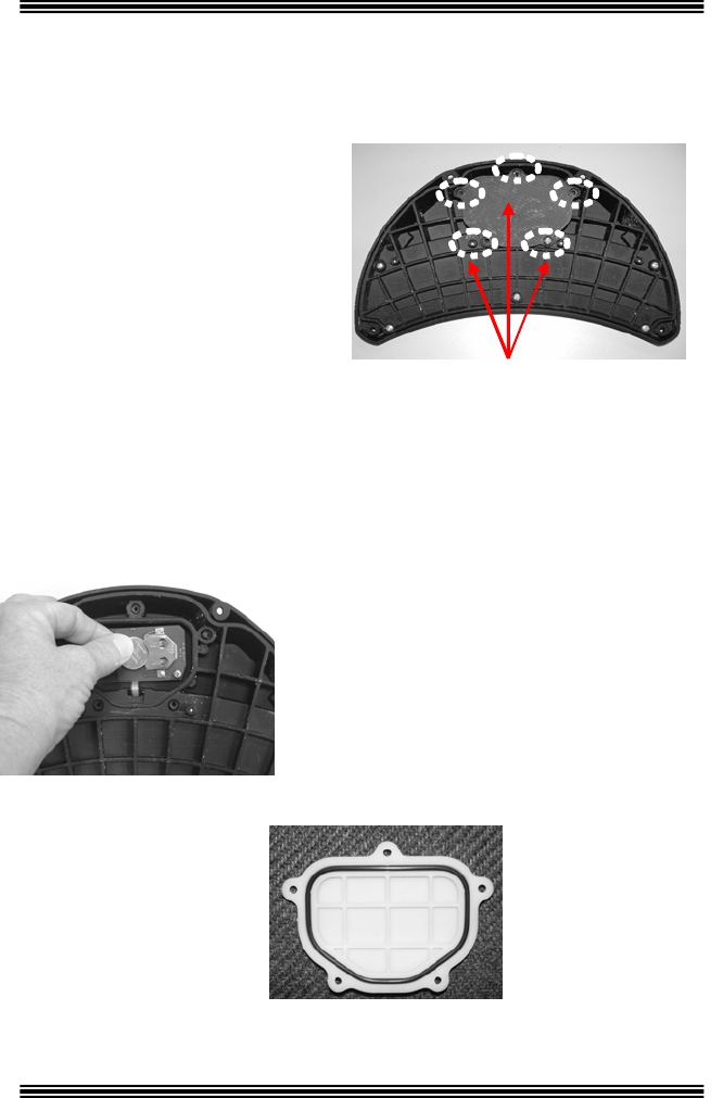
Foo lacement
ollow these instructions to change
2. Remove the battery cover pl
3. Using a pencil, push the battery out of its holder.
5. Ensure the O- ring is in
place on the inside
cover. Replace the cover
plate and five screws.
t-Pedal Battery Rep
Use only a 3V lithium type CR2032
replacement battery. These
atteries are not rechargeable. b
F
the battery:
1. Remove the five screws
on the battery cover plate
located on the underside
of the foot-pedal.
ate.
4. With the “+” symbol facing up, slide
the new battery in the holder.
Location of Screws Securing Battery
Cover Plate to Foot-Pedal

MOTORGUIDE WIRELESS
90-MM5997 For Questions, Contact Consumer Affairs at #1-920-929-5040 22
© 2005, MotorGuide www.motorguide.com
Care & Cleaning Instructions
To keep your trolling motor looking its best:
power washer.
available in any auto store, to keep the
oking fresh.
4. ohol, solven es on the motor
plas .
ustomer Responsibilities
he motor/mount warranty does not cover items that have been subjected to
oper full value from the warranty, the
oto o d in this manual.
oap1. Periodically wash it with warm s
2. Do not use a high pressure or
3. Use a vinyl/rubber UV protector,
cables lo
y water and a soft cloth or sponge.
Never use harsh chemicals, alc
tics, rubber or painted parts ts or abrasiv
C
Tator abuse or negligence. To receive
r/m unt must be maintained as instructem
eeds, fishing
or other d ler or the
Check behind the propeller after each use to ensure w
line ebris are not rapped around the propelw
propeller shaft.
Periodically lubricate al
aerosol lubrican
part of the unit. Many spr
l the latch pins and clamp screws with a non-
t. Never use an aerosol lubricant to grease or oil any
a lubricants contain harmful propellants that
can cause damage to various parts of your trolling motor.
y
Check the tightness of the batte ery l ad connections.
Periodically inspect for loose or corroded wiring connections.
Thoroughly rinse your trolli motor with freshwater after each use in
saltwater. ng
Periodically make a visual inspection for tightness of all nuts, bolts and
screws.
Bef re or after use, s. o periodically check the prop nut for tightnes
Battery
echarge e. Follow the battery manufactur
ndations for battery maintenance. Have your batteries tested
annually to ensure quality of operation.
Always disconnect the trolling motor battery when not in use.
your batteries after each us er’s R
recomme
CAUTION
MOTORGUIDE WIRELESS
90-MM5997 For Questions, Contact Consumer Affairs at #1-920-929-5040 23
© 2005, MotorGuide www.motorguide.com
Freezing Temperature Storage
ot be affected by freezing temperatures.
Store your trolling motor where it will n
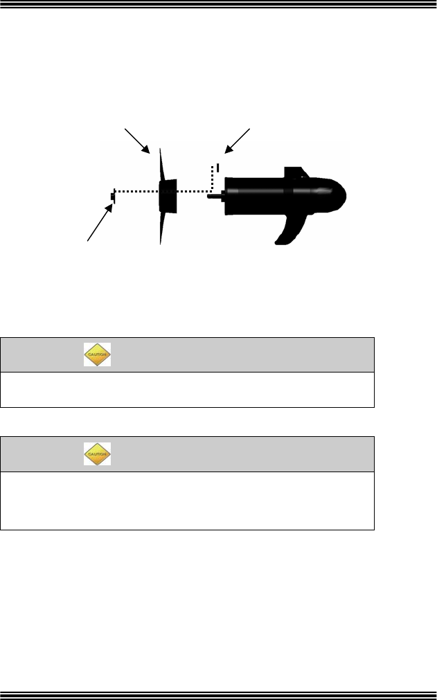
Installing or Replacing the Propeller
See the “Accessories” section of this manual to order a replacement
propeller.
M ke sure the motor is disconnected from the battery
before replacing the propeller.
a
D not strike a bent prop pin with a hammer to remove the
. This may
o
pin cause damage to the armature, which is not
o
pli
c vered by warranty. MotorGuide recommends using
ers.
handling the prop, first check for sharp edges or wear protective
peller straight off. If the prop is stuck, grasp one blade with one
with a rubber
1) When
gloves to prevent cuts to the hands.
2) While holding the propeller blade, use a prop wrench to loosen and
remove the propeller nut.
3) Pull the pro
hand and tap lightly on the backside of the opposite blade
CAUTION
CAUTION
Propeller Pin Propeller
Propeller Nut

MOTORGUIDE WIRELESS
90-MM5997 For Questions, Contact Consumer Affairs at #1-920-929-5040 24
© 2005, MotorGuide www.motorguide.com
mallet. If necessary, repeat the procedure on all blades until the propeller
) If the propeller pin is bent, replace it.
r pin.
) tighten sec with your fingers. Tighten
another 1/4 turn using a MotorGuide Prop Wrench, part number
MGA050B6.
comes off.
4
5) Align the new propeller with the propelle
6ller nut and urelyReinstall the prope

MOTORGUIDE WIRELESS
90-MM5997 For Questions, Contact Consumer Affairs at #1-920-929-5040 25
© 2005, MotorGuide www.motorguide.com
TROUBLESHOOTING
Fr uently Asked Questions eq
n on the foot-pedal but
nothing happens.
A
ed; refer to the “Activating the Electronic ID number”
section of this manual.
Q Activating the electronic ID number does not work.
A The receiver’s memory might be full, see the “Erasing the Receiver’s
Memory” section of this manual.
Q I pressed the test button on the battery indicator and all of the
lights came on at once.
A All lights on the battery indicator illuminated at once means the
steering or trolling motor have been overloaded. Wait for the unit to
cool down. If the system does not return to normal after cooling,
contact your nearest Service Center.
Q The system stopped working.
A Check the battery in the foot-pedal and replace if necessary.
Q The receiver beeps when I press a butto
The receiver does not have the foot-pedals electronic ID number
programm
PROBLEM POSSIBLE CAUSES AND/OR SOLUTIONS
Loss of power • The propeller may be fouled. Remove the
propeller; clean or replace if necessary.
• The battery connections may be corroded.
• The battery may have low voltage. Recharge
and test for a bad cell.
• The wire gauge from the battery to the trolling
motor may be insufficient. (Six-gauge wire is
recommended.)
• A bad or faulty connection or pinched wire
could exist in the boat wiring or trolling motor
wiring.
• The permanent magnets may be cracked or
chipped. The motor will whine or grind.
• There may be water in the lower unit.

MOTORGUIDE WIRELESS
90-MM5997 For Questions, Contact Consumer Affairs at #1-920-929-5040 26
© 2005, MotorGuide www.motorguide.com
Motor makes excessive • The propeller may be fouled. Remove the
eller; clean or replace if necessary.
he propeller may be loose. Check to see if the
eller is secure.
armature may be bent. Remove the
he unit on and look for the shaft to
wobble.
op
y hand; it should turn freely with a slight
worn out.
noise or vibrates
excessively prop
• T
prop
• The
propeller and set the motor at medium speed.
Turn t
• The magnets may be interfering with the
armature. Turn the power is off. Turn the pr
b
magnetic drag.
• The bearings or bushings may be
Mo s to run at any
speed
• Check the trolling motor fuse/circuit breaker on
the boat.
• Check for lo
tor fail
ose or corroded connections.
d; it should turn freely with a slight magnet
• Check the plug for a loose or bad connection.
• Make sure the power is off. Turn the prop by
han
drag.
Motor loses one or
more speeds
• The propeller may be fouled. Remove the
propeller; clean or replace if necessary.
Mount is t is designed to easily release
am locking mechanism is loosened.
y release, it is typically due to
mount
at
hard to latch • Your bow moun
to the mount base plate when the c
If it does not easil
the cam lock not being loosened or the
base plate is not mounted evenly on the bo
deck. of
• It is possible the pivot pin on the underside
the mount is not secured by the large flange
hook.
• It is also possible that the cam lock mechanism
at the back of the mount it not fully engaged.
Check to ensure the cam lock is properly
tightened.
Battery drains
• occur if your motor remains
ll a
otor.
Voltage drain will
continually connected to your battery. Insta
power disconnect switch or disconnect the
trolling m
Motor automatically
throttles back
• Refer to your nearest Service Dealer for
assistance with trolling motor repairs.

MOTORGUIDE WIRELESS
90-MM5997 For Questions, Contact Consumer Affairs at #1-920-929-5040 27
© 2005, MotorGuide www.motorguide.com
Refer to your nearest Service ce with trolling motor
repairs.
Dealer for assistan
INFORMATION
FOR REPAIR SERVICE
Contact your nearest
complete listing of Se
our MotorGuide web site
MotorGuide Service Dealer. See a
rvice Dealers in the US and Canada at
: www.motorguide.com.
sumer Affairs to
Call Mercury Marine Con obtain the name
and location of the S
Australia Pacific: 61-3-9
Canada:
Europe, Africa & Middl
Japan:
Latin America:
Singapore: 65-6546
ervice Dealer nearest you.
United States: 1-920-929-5040
791-5822
905-816-4751
e East: 32-87-323-211
81-53-423-2500
954-744-3500
-6160
REPLACEMENT PARTS AND ORDERING
MotorGuide has establis
Distributors throughout t
the following information
Service Dealer to order p
• Model Num
• Serial Number
• Part Numb
hed Service Dealers as Parts
he United States and Canada. Have
ready and contact the nearest
arts:
ber
e
r
MOTORGUIDE WIRELESS
90-MM5997 For Questions, Contact Consumer Affairs at #1-920-929-5040 28
© 2005, MotorGuide www.motorguide.com
MOTORGUIDE ACCESSORIES
Making It More Perfect. Who says you cannot make the best even better? MotorGuid
actory acce e®
ssories let fishermen customize motors to their own unique needs. In
ddition, every one is a perfect fit.
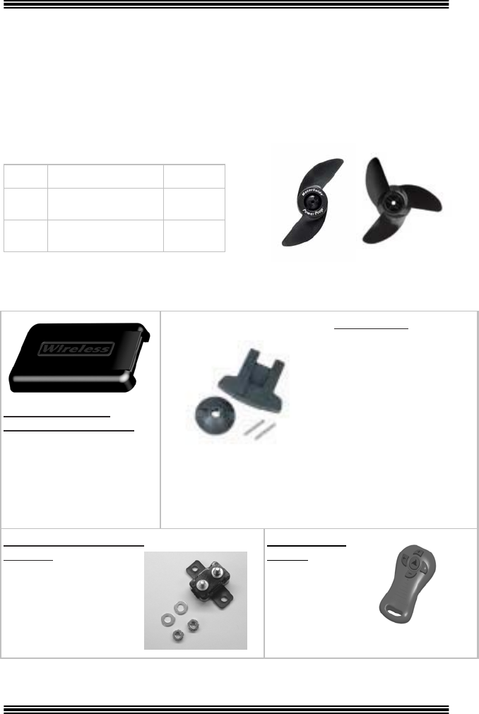
EPLAC
Description Number
f
a
R EMENT PROPS
Prop
3
P.5" 2 Blade Power
op MGA0495
r
#12
3
3.5" Machette III, MGA087B
Blade
#16
ADDITIO
nap-on
NAL HARDWARE ACCESORIES
S Wireless
Mounting Plate Cover
MGA506
rotective co r converts
ounting plat
hen your troll
ot in use.
Prop Wench
MGA050B6
Comes complete with
spare prop nut and two
prop pins, allowing fast
anges. prop ch
A1
P ve
m e to a step
w ing motor is
n
50 Amp Circuit Breaker
MM5870
Protects trolling motor
and boat wiring from
connection failures
and is a safety must.
DRC–Remote
Control
M887657
Digital RF
Wireless
Remote Key
FOB

MOTORGUIDE WIRELESS
90-MM5997 For Questions, Contact Consumer Affairs at #1-920-929-5040 29
© 2005, MotorGuide www.motorguide.com
MOTORGUIDE LIMITED THREE-YEAR WARRANTY
Keep your original purchase receipt)
nd
are warranted to the original retail purchaser to be free
om defects in material and/or workmanship for a period of three (3) years from the date of
urchase. This Limited Warranty begins on the date the product is first sold to a retail
e product is first put
ucts receive coverage for one (1) year from the date of first
tail sa MotorGuide Ac essories are covered by this Limited Warranty for a coverage
he dat
arr rod due to abuse, i.e., bent columns, bent armature
shafts, br ntrol cables, etc., accidents, modifications, misuse, excessive wear or
e c r’s fail e reasonable and necessary installation or care.
ng by than an authorized Service Dealer will void this
arranty. arranty service, the purchaser should deliver or return the unit (postage
repaid and insured) to any MotorGuide Authorized Service Dealer. Products returned by mail
ould also be carefully packaged and include a note describing the nature of the problem
ase or registration verification is required
otorGuide, at its discretion, will
under the terms of this warranty. Neither MotorGuide nor
e responsible for damages to MotorGui
repairs performed by anyone other than an authorized MotorGuide Se ther
MotorGuide nor Mercury Marine is responsible for failure or damage ca
installation, set-up, preparation, or previous service or repair errors.
The product registration must be processed by MotorGuide within ten ate
our warranty. MotorGuide products requiring s d
ty may be repaired or replaced for a reasonable fee. ALL
EQUENTIAL DAMAGES ARE EXCLUDED FROM THIS
MPLIED WARRANTIES ARE LIMITED TO THE LIFE OF THIS WARRANTY.
SOME STATES DO NOT ALLOW LIMITATIONS ON HOW LONG AN IMPLIED WARRANTY
R LIMITATION OF INCIDENTAL OR CONSEQUENTIAL
MITATIONS OR EXCLUSIONS MAY NOT APPLY TO YOU.
ECIFIC LEGAL RIGHTS, AND YOU MAY ALSO HAVE
MAY VARY FROM STATE TO STATE.
____________
___
o any subsequent purchaser n of the unused warranty
period.
2 Commercial use is defined as any work or employmen product, or any use
of the product which generates income, for any part of th nty period, even if the product
is only occasionally used for such purpose.
(
For recreational use customers, MotorGuide Tour, Digital Freshwater, Digital Steering, a
Saltwater Series electric trolling motors 1
fr
p
purchaser or the date on which th
ommercial into service, whichever occurs first.
2 users of these prod
C
re le.
period of c
one (1) year from t e of retail sale.
This w anty does not cover p
oken co uct damage
damag
Openi aused by an owne
the lower unit (motor)
To obtain w
ure to provid
anyone other
w
p
sh
and/or service requested. A copy of the proof of purch
ith the return of the product for warranty consideration. Mw
repair or replace items covered
MotorGuide Service Dealers ar de products due to
rvice Dealer. Nei
used by improper
(10) days from the d
ervice not covereof purchase to validate y
under the terms of this warran
INCIDENTAL AND\OR CONS
WARRANTY. I
LASTS OR THE EXCLUSION O
DAMAGES, SO THE ABOVE LI
THIS WARRANTY GIVES YOU SP
OTHER LEGAL RIGHTS WHICH
For Your Records:
Model Number_____________________ _________
____
Serial Number______________________________
1 Warranty is transferable t for the duratio
t-related use of the
e warra

MOTORGUIDE WIRELESS
90-MM5997 For Questions, Contact Consumer Affairs at #1-920-929-5040 30
© 2005, MotorGuide www.motorguide.com
OUR
IS INCLUDED IN THE BOX AND IS SEPARATE
hank you for purchasing and registering
IMPORTANT!!
REGISTER Y
PRODUCT
The warranty registration card (located in the box) should be completed and
mailed to Mercury Marine to validate your warranty. To replace a lost warranty
card, contact the Mercury Marine Registration Department at 1-920-929-5054.
WARRANTY CARD
REGISTRATION
FROM THIS MANUAL.
PLEASE FILL OUT AND MAIL IMMEDIATELY TO
VALIDATE YOUR WARRANTY.
T
this MotorGuide product.

835 W. 41 Street
MotorGuide
st
Tulsa, Oklahoma 74107
(920) 929-5040