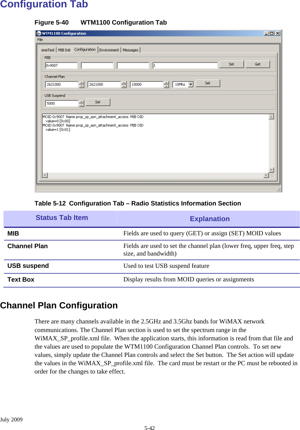
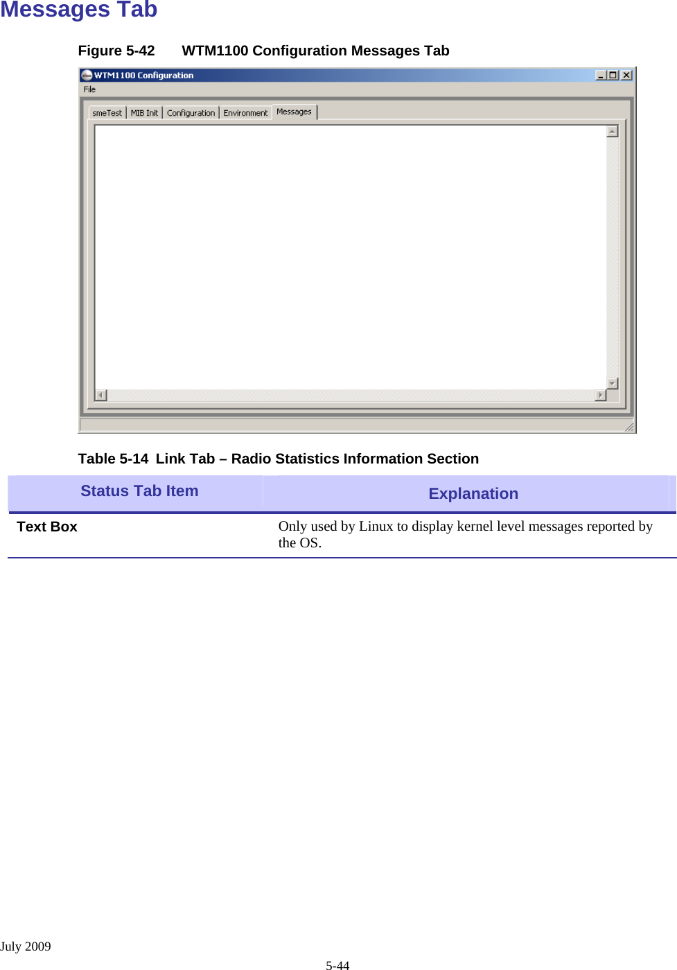
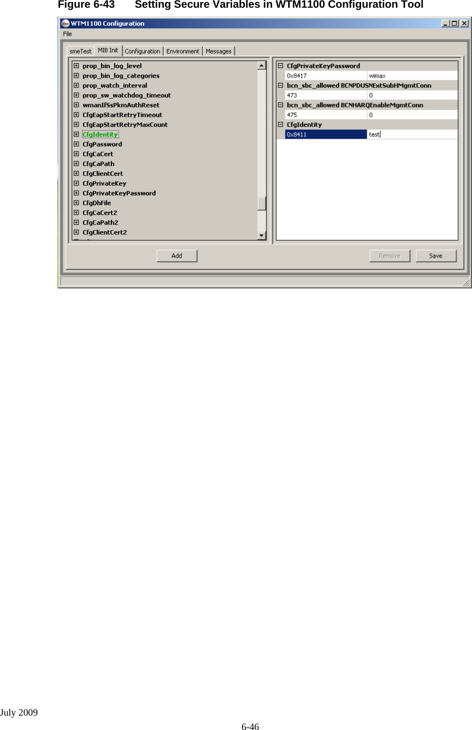
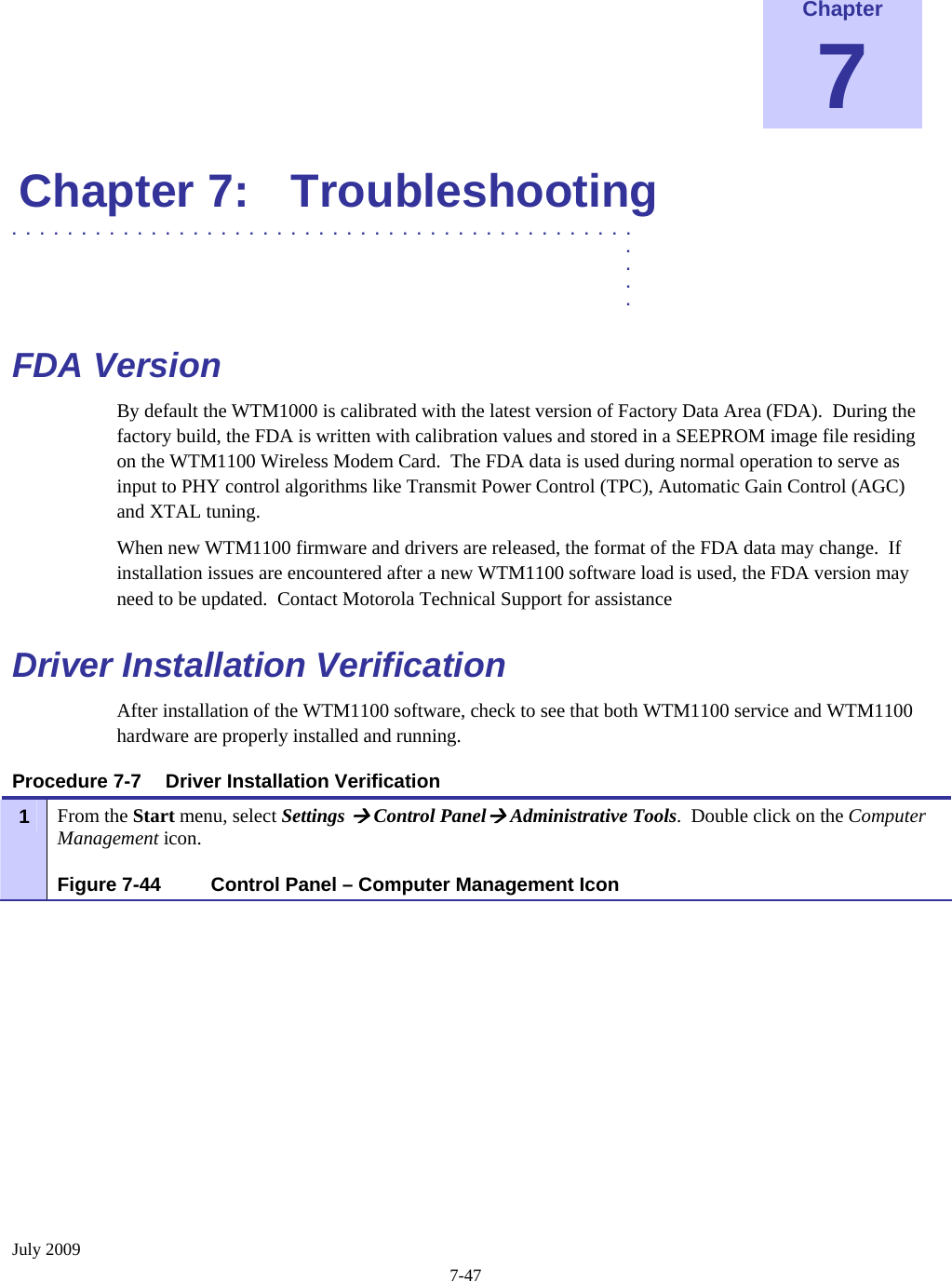
Motorola Mobility P56KM4 WiMAX Transceiver Card User Manual WTM1100 Wireless Modem Card Users Guide

Motorola Mobility LLC WiMAX Transceiver Card WTM1100 Wireless Modem Card Users Guide

Exhibit 8 Users Manual

      WTM1100  Wireless Modem Card Users Guide                July 2009
WTM1100 Wireless Modem Card Users Guide July 2009 ii  Copyrights The Motorola products described in this document may include copyrighted Motorola computer programs. Laws in the United States and other countries reserve for Motorola certain exclusive rights for copyrighted computer programs. Accordingly, any copyrighted Motorola computer programs contained in the Motorola products described in this document may not be copied or reproduced in any manner without the express written permission of Motorola. Furthermore, the purchase of Motorola products shall not be deemed to grant either directly or by implication, estoppels or otherwise, any license under the copyrights, patents or patent applications of Motorola, except for the normal nonexclusive, royalty-free license to use that arises by operation of law in the sale of a product.  © 2009 Motorola, Inc. All rights reserved. No part of this document may be reproduced, transmitted, stored in a retrieval system, or translated into any language or computer language, in any form or by any means, without the prior written permission of Motorola, Inc.  Disclaimer Please note that certain features, facilities and capabilities described in this document may not be applicable to or licensed for use on a particular system, or may be dependent upon the characteristics of a particular mobile subscriber unit or configuration of certain parameters. Please refer to your Motorola contact for further information. Trademarks Motorola, the Motorola logo, and all other trademarks identified as such herein are trademarks of Motorola, Inc. All other product or service names are the property of their respective owners.
July 2009 iii  Table of Contents  Contents .............................................  .  .  .  . Chapter 1: Introduction...........................................................................................1-1 General System Requirements.............................................................................................................................. 1-3 Windows XP Minimum System Requirements................................................................................................ 1-3 Ubuntu 8.04 Minimum System Requirements................................................................................................. 1-3 What’s in the Box............................................................................................................................................. 1-3 External Connections ....................................................................................................................................... 1-4 Chapter 2: Software Installation.............................................................................2-5 Installing WTM1100 Client Software on Windows XP ....................................................................................... 2-5 Installing WTM1100 Client Software on Ubuntu 8.04....................................................................................... 2-12 Chapter 3: WTM1100 Installation .........................................................................3-13 Working with the Card Extender ........................................................................................................................ 3-13 Connecting the Card Extender Assembly ...................................................................................................... 3-13 Installing the WTM1100..................................................................................................................................... 3-15 Installing the WTM1100 Wireless Modem Card ........................................................................................... 3-15 Removing the WTM1100................................................................................................................................... 3-28 Chapter 4: Radio Statistics...................................................................................4-30 Starting Radio Statistics...................................................................................................................................... 4-30 Radio Statistics Tab Contents............................................................................................................................. 4-31 Link Tab......................................................................................................................................................... 4-31 MAC Tab ....................................................................................................................................................... 4-32 SFlow Tab...................................................................................................................................................... 4-34 Version Tab.................................................................................................................................................... 4-35 Settings Tab.................................................................................................................................................... 4-36 Info Tab.......................................................................................................................................................... 4-37 Log Tab.......................................................................................................................................................... 4-38 Chapter 5: WTM1100 Configuration Tool ............................................................5-39 smeTest Tab................................................................................................................................................... 5-40 MIB Init Tab .................................................................................................................................................. 5-41 Configuration Tab .......................................................................................................................................... 5-42 Channel Plan Configuration.........................................................................................................................................5-42 Environment Tab............................................................................................................................................ 5-43 Messages Tab................................................................................................................................................. 5-44
List of Figures July 2009 iv Chapter 6: Network Settings ................................................................................6-45 Using DHCP .................................................................................................................................................. 6-45 Secure Network Configuration....................................................................................................................... 6-45 Chapter 7: Troubleshooting .................................................................................7-47 FDA Version....................................................................................................................................................... 7-47 Driver Installation Verification .......................................................................................................................... 7-47 Verify Network Connection Established............................................................................................................. 7-50 Verify PEM files mapping to Specific Names ..................................................................................................... 7-52 WTM1100 PEM File Names: ........................................................................................................................ 7-52 Authentication Settings ....................................................................................................................................... 7-52 For WTM1100 TTLS authentication: ............................................................................................................ 7-52 On the Network Infrastructure Side: .............................................................................................................. 7-52 Authentication off:.......................................................................................................................................................7-52 Authentication on:........................................................................................................................................................7-53 From an EMS, DAP/Configuration/SubscriberRestrictions Settings:..........................................................................7-53 Chapter 8: Customer Information ........................................................................8-54 Customer Service Information............................................................................................................................ 8-54 Obtaining Support.......................................................................................................................................... 8-54 System Information......................................................................................................................................................8-54 Return Material Request ..............................................................................................................................................8-55 Returning System Components to Motorola................................................................................................................8-55 Returning FREs............................................................................................................................................................8-55 Chapter 9: Certification and Safety Information .................................................9-57 FCC and CE Regulatory Information ................................................................................................................. 9-57 FCC and CE Information ............................................................................................................................... 9-57 FCC RF Radiation Exposure Statement......................................................................................................... 9-57 Safety Information for the WTM1100 Product................................................................................................... 9-57 General Safety Information............................................................................................................................ 9-58 Safety Certification ........................................................................................................................................ 9-58 WTM1100 Product Label Example ............................................................................................................... 9-60
 July 2009 v  List of Figures  List of Figures .............................................  .  .  .  . Figure 1-1 WTM1100 Dimensions....................................................................................................1-1 Figure 1-2 WTM1100 showing Antenna Port and LED Indicators...................................................1-4 Figure 2-3 WTM1100 Setup - Welcome Dialog (XP) ......................................................................2-6 Figure 2-4 WTM1100 Setup – Startup Options (XP)........................................................................2-7 Figure 2-5 WTM1100 Setup - Ready to Install (XP) ........................................................................2-7 Figure 2-6 WTM1100 Setup - Installing Files Window (XP)...........................................................2-9 Figure 2-7 Software Installation Dialog Box...................................................................................2-10 Figure 2-8 Software Installation Dialog Box...................................................................................2-10 Figure 2-9 Software Installation Dialog Box – Select Options .......................................................2-11 Figure 2-10 WTM1100 Setup - WTM1100 Installed Successfully (XP)..........................................2-12 Figure 3-11 Attach the Card Extender to the WTM1100..................................................................3-13 Figure 3-12 Locating the Mini-PCIE Card Slot ................................................................................3-15 Figure 3-13 Installing the WTM1100 Card.......................................................................................3-16 Figure 3-14 Proper Orientation of WTM1100 Inside Laptop............................................................3-17 Figure 3-15 Connecting Internal Antennas to the WTM1100 Card..................................................3-17 Figure 3-16 Found New Hardware Wizard – Serial PC Card ...........................................................3-18 Figure 3-17 Found New Hardware Wizard - Loading Files..............................................................3-19 Figure 3-18 Hardware Installation Dialog Box .................................................................................3-20 Figure 3-19 Found New Hardware Wizard – Installing Software.....................................................3-21 Figure 3-20 Found New Hardware Wizard – Complete....................................................................3-22 Figure 3-21 Found New Hardware Wizard .......................................................................................3-23 Figure 3-22 Found New Hardware Wizard - Loading Files..............................................................3-24 Figure 3-23 Hardware Installation Dialog Box .................................................................................3-25 Figure 3-24 Found New Hardware Wizard Loading Files ................................................................3-26 Figure 3-25 Hardware Installation Dialog Box .................................................................................3-27 Figure 3-26 Found New Hardware - Wizard Complete ....................................................................3-27 Figure 3-27 Unplug or Eject Hardware Icon.....................................................................................3-28 Figure 3-28 Safe to Remove Hardware - WTM1100 Card ...............................................................3-29 Figure 3-29 Removing the WTM1100 Software...............................................................................3-29 Figure 4-30 Starting Radio Statistics.................................................................................................4-31 Figure 4-31 Radio Statistics Link Tab...............................................................................................4-32 Figure 4-32 Radio Statistics MAC Tab .............................................................................................4-33 Figure 4-33 Radio Statistics SFlow Tab............................................................................................4-34 Figure 4-34 Radio Statistics Version Tab..........................................................................................4-35 Figure 4-35 Radio Statistics Settings Tab .........................................................................................4-36 Figure 4-36 Radio Statistics Info Tab................................................................................................4-37 Figure 4-37 Radio Statistics Log Tab................................................................................................4-38 Figure 5-38 WTM1100 Configuration smeTest Tab.........................................................................5-40
 July 2009 vi Figure 5-39 WTM1100 Configuration MIB Init Tab........................................................................5-41 Figure 5-40 WTM1100 Configuration Tab.......................................................................................5-42 Figure 5-41 WTM1100 Configuration  Environment Tab ................................................................5-43 Figure 5-42 WTM1100 Configuration Messages Tab.......................................................................5-44 Figure 6-43 Setting Secure Variables in WTM1100 Configuration Tool .........................................6-46 Figure 7-44 Control Panel – Computer Management Icon................................................................7-47 Figure 7-45 Windows Services Window...........................................................................................7-48 Figure 7-46 Local Area Connection Properties Dialog Box..............................................................7-48 Figure 7-47 Windows Services Window...........................................................................................7-49 Figure 7-48 WTM1100 Driver Version.............................................................................................7-49 Figure 7-49 Control Panel – Computer Management Icon................................................................7-50 Figure 7-50 IPCONFIG Window ......................................................................................................7-51
 July 2009 vii   List of Tables  List of Tables .............................................  .  .  .  . Table 1-1   Pin Designators................................................................................................................1-1 Table 1-2   WTM1100 Specifications................................................................................................1-2 Table 4-3 Link Tab – Radio Statistics Information Section...........................................................4-32 Table 4-4 MAC Tab – Radio Statistics Information Section .........................................................4-33 Table 4-5 SFlow Tab – Radio Statistics Information Section........................................................4-34 Table 4-6 Version Tab – Radio Statistics Information Section......................................................4-35 Table 4-7 Settings Tab – Radio Statistics Information Section .....................................................4-36 Table 4-8 Info Tab – Radio Statistics Information Section............................................................4-37 Table 4-9 Log Tab – Radio Statistics Information Section............................................................4-38 Table 5-10 smeTest Tab – smeTe3st Information Section...............................................................5-40 Table 5-11 MIB Init Tab – MIB Init Information Section...............................................................5-41 Table 5-12 Configuration Tab – Radio Statistics Information Section............................................5-42 Table 5-13 Link Tab – Radio Statistics Information Section...........................................................5-43 Table 5-14 Link Tab – Radio Statistics Information Section...........................................................5-44
 July 2009 viii  List  of Procedures  List of Procedures .............................................  .  .  .  .  Procedure 2-1 WTM1100 Client Software Installation on Windows XP...........................................2-5 Procedure 2-2 WTM1100 Client Software Installation on Windows 2000......................................2-12 Procedure 3-3 Connecting the Card Extender Assembly..................................................................3-13 Procedure 3-4 Installing the Wireless Modem Card.........................................................................3-15 Procedure 3-5 Removing the WTM1100 Card.................................................................................3-28 Procedure 4-6 Starting Radio Statistics ............................................................................................4-30 Procedure 7-7 Driver Installation Verification .................................................................................7-47
 July 2009 1-1 Chapter 1 Chapter 1:  Introduction  .............................................  .  .  .  . This guide will assist you with the use, installation, and configuration of the WTM1100 Wireless Modem Card (WMC). The WTM1100 is in a half mini-PCIe form factor.  Due to the physical similarities of WMC cards, many of the explanations and procedures described in this manual apply to other Motorola WMC cards (HTM1000, LTM1000) except where expressly noted. In addition, a section describing the Radio Statistics application, which is used for direct user interface with the Wireless Modem Card, is also included.  The WTM1100 is an IEEE 802.16e Wave 2 compliant, single-band Half Mini-PCIe wireless network adapter that operates in the 2.5 GHz or 3.5 GHz spectrum for WiMAX connectivity. This product is available in Half-Mini Card form factor with optional extender for Full-Mini slots. This integrated module provides high performance broadband wireless connectivity to a wide range of next generation mobile, low power consumer electronic devices to enhance today’s mobile lifestyles.    Signal  PIN(s)  Signal  Direction  Description 02, 24, 39, 41, 52  +3.3VAUX     3.3V Source Power  04, 09, 15, 18, 21, 26, 27, 29, 34, 35, 37, 40, 43, 50  GND     Ground 38 USB_D+ Input/Output USB2.0 Serial Data Interface Universal Serial Bus (USB)  36 USB_D- Input/Output USB2.0 Serial Data Interface Auxiliary Signals (3.3V Compliant)  22 PERST# Input  System Power Stable Indication and Functional Reset 44 LED_WLAN# Output LED Status Indicator (Open Drain Active Low) 42 LED_WWAN# Output LED Status Indicator (Open Drain Active Low) 20  W_DISABLE#  Input  Disable Radio Operation  03 COEX1 Input Wireless Coexistence Mini-PCIe Interface  Specific Signals 05 COEX2 Output Wireless Coexistence Figure 1-1  WTM1100 Dimensions   Table 1-1 Pin Designators
 July 2009 1-2  WTM1100 PCIe Half-Mini Card Specifications Standard  IEEE 802.16e WiMAX Forum® Compliant Wave 2, CRSL 6.0 Frequency Band  2.495GHz – 2.695GHz  3.3GHz - 3.6GHz Channel Bandwidth  5MHz, 10MHz                                   5MHz, 7MHz, 10MHz Mobile Profile  MP05  MP10, MP11, MP12 Maximum Output Power  23dBm Sensitivity  -94dBm (10MHz QPSK-CTC3/4), -88dBm (10MHz, 16QAM-CTC3/4),     -81dBm (10MHz 64QAM-CTC3/4) MIMO  2RX+1TX Supporting MRC,STC Matrix A / SM Matrix B Duplex/Multiple Access  TDD/OFDMA RF Modulation  BPSK/QPSK/16QAM/64QAM FFT  512 and 1024 Decoder Engine  Quad FEC, 34Mbps Downlink Throughput End to End Throughput  DL - 16Mbps ; UL - 4.5Mbps Bursts  64 Concurrent Downlink, 7 Concurrent Uplink Payload  IP Header Suppression, IPv4, IPv6, Packing/Fragmentation, ARQ QoS  BE, UGS, RT-VR, NRT-VR, ERT-VR Antenna Connector  Hirose UFL Ultra-Miniature SMT Host Interface  Mini-PCI Express v1.2 (USB 2.0 Electrical Interface) Security Authentication  EAP-TLS, EAP-TTLS, PKMv2, CMAC and Security Associations Cryptographic Suites  3-DES,128 CCM-Mode, 128-AES, AES Key Wrap Device Driver Client Software  Connection Manager, Radio Statistics, WTM1100 Configuration  Supported Operation Systems  Windows XP, Linux, Windows Mobile 6.0 Planned OS Support  Windows CE 6.0, Android, Windows Vista, Windows 7 Power (RMS) Supply 3.3V DC Power Consumption (TX) High Power  2.07W  Power Consumption (TX) Low Power  1.79W Power Consumption (Rx)  1.12W (HD Video Streaming) Sleep Mode  <3mW Idle Mode  <78mW Physical Dimension  30mm x 26.8mm x 4.5mm (Double Sided) LED Indicators  LEDWLAN# or LEDWWAN# Supported Environmental Ambient Temperature Range  -25°C to +65°C (Ambient Temperature Exposed to Card) Available Options USB Adapter   USB Dongle Adaptor Board w/ Internal Antennas Card Slot Extender  PCIe Half-Mini to Full-Mini extension  Table 1-2 WTM1100 Specifications
 July 2009 1-3 General System Requirements .............................................  .  . Host computers must comply with the following minimum requirements to ensure optimal performance of the WTM1100 WMC. Windows XP Minimum System Requirements • Laptop or Notebook PC running the Microsoft Windows XP (Service Pack 2) operating system • 500 MHz Processor • 10 MB of available hard disk storage • Keyboard, Mouse, CD-ROM drive or DVD drive • Available MINI-PCIE V2 card slot in the Host device Ubuntu 8.04 Minimum System Requirements • Laptop or Notebook PC running the Ubuntu 8.04 operating system and/or LiveCD provided by Motorola • 500 MHz Processor • 10 MB of available hard disk storage • Keyboard, Mouse, CD-ROM drive or DVD drive • Available MINI-PCIE V2 card slot in the Host device • Update and Install packages (ssh, libpcre3, libgtk2.6-0, iperf)  What’s in the Box Each WTM1100 WMC is a full-featured wireless networking interface.  The following is a list of the items provided with each Wireless Modem Card: • WTM1100 Wireless Modem Card • Half to Full MINI PCIE card extender  (Optional) • WTM1100 Wireless Modem Card Software and Documentation CD ROM The CD ROM contains a PDF version of the Wireless Modem Card User’s Guide.  The CD also contains an installation executable to load Adobe Acrobat Reader software if it is not already resident on your computer.
 July 2009 1-4 External Connections  The WTM1100 Wireless Modem Card is designed for insertion into an industry-standard MINI-PCIE V2 card slot located in a Host device.  The Wireless Modem Card has two antenna ports to connect the external antennas.  As shown in Figure 1-2 the left antenna UFL connector is the main transmit /receiver and the right is the secondary receiver. Figure 1-2  WTM1100 showing Antenna Port and LED Indicators   MAIN Antenna Connector AUX Antenna Connector MINI-PCIE V2 Connector
 July 2009 2-5  Chapter 2 Chapter 2:  Software Installation .............................................  .  .  .  . This chapter will assist you with the software installation portion of the process and is further separated into two main sections: Installing WTM1100 Client Software on Windows XP and Installing WTM1100 Client Software on Ubuntu 8.04. Installing WTM1100 Client Software on Windows XP  .............................................  .  . The following procedure outlines the installation of the WTM1100 client software on a typical Windows XP platform.  Some of the steps may vary slightly based on the configuration of the individual computers.  Procedure 2-1  WTM1100 Client Software Installation on Windows XP 1   Close and exit any existing WTM1100 applications running on the computer prior to installation. 2   Insert the Software and Documentation CD into the CD-ROM drive. 3   If the installation program does not start automatically, open the Windows Start menu. Click on Run then type the following into the dialog box:     d:\WiMAX_WTM1100_Installation.msi where d: specifies the CD-ROM drive and click the OK button. 4   Click the Next button to continue the installation process. 5   The WTM1100 Setup dialog box will be displayed as shown in Figure 2-3.
 July 2009 2-6 Click the Next button to continue the installation process.6  Figure 2-3  WTM1100 Setup - Welcome Dialog (XP)
 July 2009 2-7 The Select Installation Folder dialog box displays the Install Folder location.  Click the Next button to continue the installation process. 7  Figure 2-4  WTM1100 Setup – Startup Options (XP)  The Confirm Installation dialog confirms the installation is ready to commence.  Click on the Next button to proceed with the installation process.   8  Figure 2-5  WTM1100 Setup - Ready to Install (XP)
 July 2009 2-8
 July 2009 2-9 The Installing WTM1100 window displays a status bar to indicate the progress of the installation and will be automatically dismissed as soon as file installation has completed. 9  Figure 2-6  WTM1100 Setup - Installing Files Window (XP)  10  .
 July 2009 2-10 A Software Installation dialog indicates that the software is not Windows Logo tested. Select the Continue Anyway button to complete the installation process.  11 Figure 2-7  Software Installation Dialog Box  If a second Software Installation dialog box is displayed as shown in Figure 2-8.  Click on the Continue Anyway button to complete the installation process. 12 Figure 2-8  Software Installation Dialog Box  13  Select the Continue Anyway button if additional windows display on the screen containing the same screen contents as in the step above.
 July 2009 2-11 The WTM1100 Information dialog box will be displayed as shown in Figure 2-9.  This installation screen instructs the user to view the ReadMe file during the installation and to run Radio Statistics immediately following installation.  Click on the Next button to proceed with the installation process.   14 Figure 2-9  Software Installation Dialog Box – Select Options
 July 2009 2-12 From the WTM1100 Installed Successfully dialog click on the Finish button to exit.  15 Figure 2-10  WTM1100 Setup - WTM1100 Installed Successfully (XP)   Installing WTM1100 Client Software on Ubuntu 8.04  .............................................  .  . The following procedure outlines the installation of WTM1100 client software on a typical Ubuntu 8.04 platform.  Some of the steps may vary slightly based on the configuration of an individual computer. Complete the following procedure to install the WTM1100 client software: Procedure 2-2  WTM1100 Client Software Installation on Windows 2000 1   Remove any existing WTM1100 applications running on the computer prior to installation. 2   Insert the WTM1100 Software and Documentation CD into the CD-ROM drive. 3   Open a terminal window. 4   Set the linux root password >>sudo passwd 5   Install the WTM1100 software package using the following command >>dpkg –i /media/CDROM/WiMAX_WTM1100_Installation.deb
 July 2009 3-13  Chapter 3 Chapter 3:  WTM1100 Installation .............................................  .  .  .  . This chapter will assist you with the physical installation and configuration of the WTM1100 Wireless Modem Card.  Working with the Card Extender  .............................................  .  . The following sections will focus on the proper handling and usage of the card extender and ESD when using a WTM1100 card. Connecting the Card Extender Assembly Complete the following procedure to connect the Card Extender Assembly to the WTM1100 WMC for use in a standard laptop computer.  Always wear a static strap when working with the WTM1100.   Procedure 3-3  Connecting the Card Extender Assembly Locate the Card Extender adapter and align it with the WTM1100, as shown below in Figure 3-11.  The provided mating screws should come up from underneath the card with the thread protruding from the top.   1  Figure 3-11  Attach the Card Extender to the WTM1100
 July 2009 3-14   When properly aligned, the Card Extender will allow the WTM1100 to snap or screw into place inside a standard laptop PC with a full Mini-PCIe connector.   Applying force in any direction other than to secure the Card Extender may result in excess pressure being applied to the WTM1100 board and damage the card.  Use only FCC approved antennas or those provided by the vendor Optional Full Mini Extender Card   Attachment Screws
 July 2009 3-15 Installing the WTM1100  .............................................  .  . The following sections will describe the proper installation and removal of the WTM1100.  Installing the WTM1100 Wireless Modem Card Complete the following procedure to install the WTM1100 wireless modem card. The same installation procedure applies to both wireless modem card model numbers.  Procedure 3-4  Installing the Wireless Modem Card Locate an available MINI-PCIE V2 card slot in the computer.  If necessary, remove the dust cover from the slot. 1   Figure 3-12  Locating the Mini-PCIE Card Slot    Mini-PCIe Card Slot
 July 2009 3-16 To insure the correct orientation, insert the WTM1100 card into the computer’s MINI-PCIE V2 card slot at a 45 degree angle with the label side up as shown. 2    Never force the card into the slot. Figure 3-13  Installing the WTM1100 Card    Labels must be facing up
 July 2009 3-17 The WTM1100 must be pushed down and securely fastened in the MINI-PCIe V2 slot by the means provided by the laptop vendor (screw or clip) as shown in Figure 3-14. 3  Figure 3-14  Proper Orientation of WTM1100 Inside Laptop   Vendor Screw Fastener for Full Mini-PCIe slot.Connect the provided laptop antennas to the UFL connectors on the WTM1100 card.  The UFL connectors will snap down when properly connected to the WTM1100.  In the Figure 3-15 below, the blue antenna lead is for the MAIN antenna and the white is for the AUX antenna.   4  Figure 3-15  Connecting Internal Antennas to the WTM1100 Card.     Internal Antenna Leads
 July 2009 3-18 The first time the PC is booted with the WTM1100 card, a message will be displayed indicating that the WTM1100 card has been found.  The Windows Found New Hardware Wizard for the WTM1100  will start as shown in Figure 3-16.  Select “No, not this time” to prevent Windows from searching externally for the WTM1100 DFU driver, and then click on the Next button. Figure 3-16  Found New Hardware Wizard – Serial PC Card 5
 July 2009 3-19 6   The Found New Hardware dialog will display a window to help install the WTM1100 DFU software.  Verify that the “Install the software automatically (Recommended)” radio button is selected, and then click on the Next button.  Figure 3-17  Found New Hardware Wizard - Loading Files
 July 2009 3-20 As soon as the above step is complete, the Hardware Installation dialog box shown in Figure 3-18 will be displayed.  Click on the Continue Anyway button in the Hardware Installation dialog box. 7  Figure 3-18  Hardware Installation Dialog Box
 July 2009 3-21 8   The Found New Hardware Wizard will begin installing the WTM1100 DFU installation files and display the progress information for establishing the restore point and backing up of old files as shown in Figure 3-19.  Wait for this step to complete. Figure 3-19  Found New Hardware Wizard – Installing Software
 July 2009 3-22 After successfully loading the WTM1100 DFU driver, the Found New Hardware Wizard will complete.  Click on the Finish button 9   Figure 3-20  Found New Hardware Wizard – Complete
 July 2009 3-23 An additional Found New Hardware Wizard will be displayed as shown in Figure 3-21.  Select “No, not this time” to prevent Windows from searching externally for the WTM1100 USB driver, and then click on the Next button.   Figure 3-21 Found New Hardware Wizard 10
 July 2009 3-24 The Found New Hardware dialog will display a window to help install the WTM1100 USB software.  Verify that the “Install the software automatically (Recommended)” radio button is selected, and then click on the Next button.  Figure 3-22  Found New Hardware Wizard - Loading Files 11
 July 2009 3-25 As soon as the above step is complete, the Hardware Installation dialog box shown in Figure 3-23 will be displayed.  Click on the Continue Anyway button in the Hardware Installation dialog box. Figure 3-23  Hardware Installation Dialog Box12
 July 2009 3-26 The Found New Hardware Wizard will begin installing the WTM1100 USB installation files as shown in Figure 3-24.  Wait for this step to complete. Figure 3-24  Found New Hardware Wizard Loading Files 13
 July 2009 3-27 After successfully loading the WTM1100 USB driver, the Found New Hardware Wizard will complete.  Click on the Finish button. 14 Figure 3-25 Hardware Installation Dialog Box The Found New Hardware pop-up window in the system tray will appear confirming that the driver installation is complete and the hardware is ready to use. 15 Figure 3-26  Found New Hardware - Wizard Complete
 July 2009 3-28 Removing the WTM1100 .............................................  .  . This section details specific WTM1100 card removal instruction to ensure that power to the card is disabled prior to removal. Complete the following procedure prior to ejecting the Wireless Modem Card from the computer.  Procedure 3-5  Removing the WTM1100 Card 1   Power down or Shutdown the PC.  Remove the card slot cover, disconnect the antennas, unscrew the Mini-PCIe fastener and remove the WTM1100 card as shown in Figure 3-27. Figure 3-27  Unplug or Eject Hardware Icon
 July 2009 3-29 2   Replace the card slot cover and power up the PC.  Wait for a message that indicates that the device may be safely removed from the system as shown in Figure 3-28. Figure 3-28  Safe to Remove Hardware - WTM1100 Card   Power up the PC. 3  For Windows:  Remove the WTM1100 software from the Windows Control Panel – Add/Remove Programs as shown in Figure 3-28.  Highlight WTM1100 and click on the Remove button. Figure 3-29  Removing the WTM1100 Software    For Ubuntu 8.04: From a terminal window type: dpkg –r Catawba
 July 2009 4-30  Chapter 4 Chapter 4:  Radio Statistics  .............................................  .  .  .  . Radio Statistics ™ is a status and configuration application that reports vital and statistical information about the WTM1100 Wireless Modem Card.  Because Radio Statistics is a polling application, it only runs when initiated by the user.   In this chapter you will learn about the available Radio Statistics features and the different ways to start Radio Statistics. Starting Radio Statistics  During the software installation process, you can choose to run Radio Statistics immediately upon completion of the installation process.   Procedure 4-6  Starting Radio Statistics  1  To start the Radio Statistics application, double-click on the Radio Statistics icon located on the desktop.  The icon will be available on the desktop only if the election to place it on the desktop has been selected at the time of Radio Statistics installation.
 July 2009 4-31 As an alternative to the above step, you can also: 2 Click on Start | Programs | Motorola | WiMAX WTM1100 | Radio Statistics  Figure 4-30  Starting Radio Statistics    Radio Statistics Tab Contents .............................................  .  . The following sections will describe the contents of all the available tabs within the Radio Statistics application, and their respective functionality. Link Tab
 July 2009 4-32 Figure 4-31  Radio Statistics Link Tab  Table 4-3  Link Tab – Radio Statistics Information Section  Status Tab Item   Explanation Indicates how often the modem is polled. Polling Interval Displays the receive signal strength of the attached WiMAX network.  Signal Strength  Displays the CINR of the receive frequency. Carrier Noise Interference Ratio N/A. Center Frequency  Transmit power of the WTM1100 modem card.  Transmit Power Network ID of the attached WiMAX network.   Current Network ID ID of the Base station the WTM1100 modem card is attached to. Current Base Station ID The IP address being used by the WTM1100 modem card. IP Address  MAC Address    The MAC address being used by the WTM1100 modem card. MAC Tab
 July 2009 4-33 Figure 4-32  Radio Statistics MAC Tab  Table 4-4  MAC Tab – Radio Statistics Information Section  Status Tab Item   Explanation Indicates how often the modem is polled. Polling Interval Indicates the modulation used by the receiver(s). RX Modulation Indicates the modulation used by the transmitter.  TX Modulation  Displays the number of packets received. Packets Received Packets Transmitted   Displays the number of packets transmitted. Packets Dropped  Displays the number of packets dropped by the network.
 July 2009 4-34 SFlow Tab Figure 4-33  Radio Statistics SFlow Tab  Table 4-5  SFlow Tab – Radio Statistics Information Section  Status Tab Item   Explanation Indicates how often the modem is polled. Polling Interval Displays the status of MAC Automatic Repeat-reQuest algorithm on the WiMAX network.  MAC ARQ   Packing  Fragmentation   Service Type  CID  Max Rate Max Burst
 July 2009 4-35 Version Tab Figure 4-34  Radio Statistics Version Tab  Table 4-6  Version Tab – Radio Statistics Information Section  Status Tab Item   Explanation Indicates how often the modem is polled. Polling Interval Displays the version of the WIP software. WIP Software Package   Displays the version of the package software.
 July 2009 4-36 Settings Tab Figure 4-35  Radio Statistics Settings Tab  Table 4-7  Settings Tab – Radio Statistics Information Section  Status Tab Item   Explanation Main - Auto Start on link up  Enable or disable Auto Start on link up Main - Stop polling on program error   Enable or disable stop polling on program error Main - Service Flows  Service Flow Format IDs Log Files - CSV   Export log file as CSV Log Files – Google Earth  Export log file as CSV Enable Application Logs Log Files – Application Enable Set Log level “Normal” or “Verbose” Log Files – Application Log Level Enable GPS polling GPS - Enable GPS - Port    Com port for attached GPS device
 July 2009 4-37 Info Tab Figure 4-36  Radio Statistics Info Tab  Table 4-8  Info Tab – Radio Statistics Information Section  Status Tab Item   Explanation GPS information  GPS  Displays link information on the NDIS interface Link   Files  Displays the location of the logging files for various formats.
 July 2009 4-38 Log Tab Figure 4-37  Radio Statistics Log Tab  Table 4-9  Log Tab – Radio Statistics Information Section  Status Tab Item   Explanation Log Window  If logging is enabled, log messages will be displayed.
 July 2009 5-39  Chapter 5 Chapter 5:  WTM1100 Configuration Tool .............................................  .  .  .  . WTM1100 Configuration™ tool is a status and configuration application that reports vital and statistical information about the WTM1100 Wireless Modem Card.   In this chapter you will learn about the available WTM1100 Configuration tool  features and the different ways to start WTM1100 Configuration. The following sections will describe the contents of all the available tabs within the WTM1100 Configuration tool.  This application can be used to configure various WiMAX components of the WTM1100 modem card.  The following sections provide details on how to configure and use the application.  The WiMAX Configuration application is segmented into five separate tabs. • smeTest – connection control commands • MIB init – add or remove entries from the mib_init.xml file • Configuration – specify frequency/spectrum range • Environment – mode selection  • Messages – displays contents of /var/log/messages fileRadio Statistics application, and their respective functionality.
 July 2009 5-40 smeTest Tab Figure 5-38  WTM1100 Configuration smeTest Tab  Table 5-10  smeTest Tab – smeTe3st Information Section  Status Tab Item   Explanation Scan  Commands the WTM1100 to Scan for networks. Connect    Commands the WTM1100 to Connect to a network. Commands the WTM1100 to Disconnect from a network.  Use with the Disconnect Options drop box. Disconnect  Command the WMT1100 to request a Handover from the network or perform a mobile initiated handover.   Handover Command the WTM11000 to report the status of its current state.  Status Disconnect Options  Use with the Disconnect button.  Options include Graceful or not, Disconnect with DHCP Release or not, etc.
 July 2009 5-41 MIB Init Tab Figure 5-39  WTM1100 Configuration MIB Init Tab  Table 5-11  MIB Init Tab – MIB Init Information Section  Status Tab Item   Explanation Lists all MOIDs available for use with the WTM1100.  When a MIB description is selected, it will highlight “GREEN” and can be expanded by clicking the “+” symbol.  Once the MIB value is highlighted, the “Add” button below will become active and if selected will add the MIB to the Text Box on the right. Left Hand Text Box Right Hand Text Box   Displays all the MIBS currently statically active for the WTM1100.  These are loaded to the WTM1100 every time the device is powered up.  Click the MIB variable number to the right of the MIB identifier and the field can be edited.  Click the “Save” button below once editing is complete.  Alternatively a MIB can be removed by selecting  the MIB description (highlight RED) and click “Remove”.
 July 2009 5-42 Configuration Tab Figure 5-40  WTM1100 Configuration Tab  Table 5-12  Configuration Tab – Radio Statistics Information Section  Status Tab Item   Explanation Fields are used to query (GET) or assign (SET) MOID values MIB Fields are used to set the channel plan (lower freq, upper freq, step size, and bandwidth) Channel Plan Used to test USB suspend feature USB suspend Text Box   Display results from MOID queries or assignments Channel Plan Configuration There are many channels available in the 2.5GHz and 3.5Ghz bands for WiMAX network communications. The Channel Plan section is used to set the spectrum range in the WiMAX_SP_profile.xml file.  When the application starts, this information is read from that file and the values are used to populate the WTM1100 Configuration Channel Plan controls.  To set new values, simply update the Channel Plan controls and select the Set button.  The Set action will update the values in the WiMAX_SP_profile.xml file.  The card must be restart or the PC must be rebooted in order for the changes to take effect.
 July 2009 5-43 Environment Tab Figure 5-41  WTM1100 Configuration  Environment Tab    Table 5-13  Link Tab – Radio Statistics Information Section  Status Tab Item   Explanation Selects the type of SREC to be downloaded to the modem when it initializes (GHS, CATL, MiniMAC, SJUX00001) Mode
 July 2009 5-44 Messages Tab Figure 5-42  WTM1100 Configuration Messages Tab  Table 5-14  Link Tab – Radio Statistics Information Section  Status Tab Item   Explanation Text Box  Only used by Linux to display kernel level messages reported by the OS.
 July 2009 6-45  Chapter 6 Chapter 6:  Network Settings .............................................  .  .  .  . Using DHCP  By default the WTM1100 is configured to use dynamically assigned IP addresses issued by the network.  If a DHCP server is not available on your network, you could choose to provide a viable static IP address given by the network provider.  Some vendors WiMAX networks only support DHCP to devices.  In these cases, Static IP assignments will not work as expected.   Secure Network Configuration  If your WTM1100 Wireless Modem Card is going to be used on a secure network, the following MIB objects need to be set.  The following objects need to be specified to gain network entry on a secure network:  • “CfgIdentity” - 8411 User Identity  • “CfgPassword” - 8412 Password • “CfgPrivateKeyPassword” - 8417 Private Key Password     • “CfgAnonymousIdentity” - 8422 Anonymous Identity   • “EAP Methods” – 841F EAP Type: TLS or TTLS (default)  These values can be added to the device’s configuration file using the WTM1100 Configuration tool as show in Figure 6-43.
 July 2009 6-46 Figure 6-43  Setting Secure Variables in WTM1100 Configuration Tool
 July 2009 7-47  Chapter 7 Chapter 7:  Troubleshooting .............................................  .  .  .  . FDA Version  By default the WTM1000 is calibrated with the latest version of Factory Data Area (FDA).  During the factory build, the FDA is written with calibration values and stored in a SEEPROM image file residing on the WTM1100 Wireless Modem Card.  The FDA data is used during normal operation to serve as input to PHY control algorithms like Transmit Power Control (TPC), Automatic Gain Control (AGC) and XTAL tuning. When new WTM1100 firmware and drivers are released, the format of the FDA data may change.  If installation issues are encountered after a new WTM1100 software load is used, the FDA version may need to be updated.  Contact Motorola Technical Support for assistance Driver Installation Verification  After installation of the WTM1100 software, check to see that both WTM1100 service and WTM1100 hardware are properly installed and running. Procedure 7-7  Driver Installation Verification  1  From the Start menu, select Settings Æ Control PanelÆ Administrative Tools.  Double click on the Computer Management icon. Figure 7-44  Control Panel – Computer Management Icon
 July 2009 7-48  2  The Computer Management window will be displayed.  On the right side, expand the Services and Applications icon and click on the Services icon.  Scroll down the list on the left side and verify that the “WiMAX WTM1100” service is started and running.   Figure 7-45  Windows Services Window  3  From the Start menu, select Settings Æ Control PanelÆ Administrative Tools.  Double click on the Computer Management icon. Figure 7-46  Local Area Connection Properties Dialog Box
 July 2009 7-49  The Computer Management window will be displayed.  On the right side, click on the Device Manager icon.  Scroll down the list on the left side and verify that the “WiMAX WTM1100 NDIS” and “WiMAX WTM1100 USB” are listed and enabled under Network Adapters.   4 Figure 7-47  Windows Services Window  5  The WTM1100 driver version can be found by double clicking the Motorola 4G NDIS device and selecting the Driver tab in the “Motorola 4G NDIS Properties” window.     Figure 7-48  WTM1100 Driver Version
 July 2009 7-50    Verify Network Connection Established  After installation of the WTM1100 software, check to see if the WTM1100 adapter has been assigned an IP address by the network.   Procedure 7-2  Network Connection Established Verification  From the Start menu, select RUN and type “cmd”.  This will open a command window. 1 Figure 7-49  Control Panel – Computer Management Icon
 July 2009 7-51  From the Command Window, type “ipconfig”.  Verify that the WiMAX network has given the WTM1100 Wireless Modem Card an IP address.   2 Figure 7-50  IPCONFIG Window
 July 2009 7-52 Verify PEM files mapping to Specific Names  When using third party Privacy-enhanced Electronic Mail (PEM) files, rename them to match the file names the WTM1100 driver is looking for in WTM1100 installation directory (default is C:\Program Files\Motorola\WTM1100 directory).   WTM1100 PEM File Names: • Commercial_device.pem  --> ServerCert.pem  • Commercial_prv_key.pem --> ServerPrivateKey.pem  • EMEA_Trials_ServerRootCert.der --> TrustCA.pem Authentication Settings  To use Tunneled Transport Layer Security (TTLS) authentication protocols several certificates may be required depending on the network infrastructure settings.   For WTM1100 TTLS authentication: • The ServerCert and ServerPrivateKey certificates may not be required by the WTM1100.   • The TrustCA is required to verify a AAA server certificate.    On the Network Infrastructure Side: In the Motorola NECB.xml file, grep for "CapCfg" and the value 2 (auth on) should change to 0 (auth off).   There are separate lines in the NECB for the CapcAuth and for the MAC message integrity checking per sector, both need to be changed when authentication is disabled.  Authentication off: • <SWI:wmanIfBsCapCfgAuthPolicyControl>00000000</SWI:wmanIfBsCapCfgAuthPolicyControl>
 July 2009 7-53 • <SWF:wmanIfBsCapCfgMacMsgAuth>0</SWF:wmanIfBsCapCfgMacMsgAuth>   Authentication on: • <SWI:wmanIfBsCapCfgAuthPolicyControl>00000002</SWI:wmanIfBsCapCfgAuthPolicyControl>     •  <SWF:wmanIfBsCapCfgMacMsgAuth>9</SWF:wmanIfBsCapCfgMacMsgAuth>   From an EMS, DAP/Configuration/SubscriberRestrictions Settings: • Auth Policy = NONE (or EAP for auth) • MAC Message ... = NONE (or CMAC0_AND_CMAC for auth)
 July 2009 8-54  Chapter 8 Chapter 8:  Customer Information .............................................  .  .  .  . This chapter lists the relevant Certification and Product Safety Information for the WTM1100 devices described in this manual. Customer Service Information  .............................................  .  . If you have read this document and made every effort to resolve installation or operation issues yourself and still require help, please contact Motorola Global Support Center (GSC) using the following contact information:  Hours of Operation 8AM to 5PM M-F Central US  Technical Support:   512-427-7256 (USA) Website:    http://www.motorola.com/ Obtaining Support Motorola provides technical support services for your system and recommends that you coordinate warranty and repair activities through the Motorola Global Support Center. When you consult the Motorola GSC, you increase the likelihood that problems are rectified in a timely fashion and that warranty requirements are satisfied. Check your contract for specific warranty and service information. System Information  To be provided with the best possible opportunity for support, collect the following system information and have it available when obtaining support. • Location of the system
 July 2009 8-55 • Date the system was put into service • Software or firmware version information for components of your system • Serial number(s) of the device(s) or component(s) requiring support • A written description of the symptom or observation of the problem: - When did it first appear? - Can it be reproduced? - What is the step-by-step procedure to cause it? • Do other circumstances contribute to the problem? For example, changes in weather or other conditions? • Maintenance action preceding problem: - Upgrade of software or equipment - Change in the hardware or software configuration - Software reload - from backup or from CD-ROM (note the version and date) Return Material Request After collecting system information, contact the Motorola Global Support Center for assistance or to obtain a Return Material Authorization (RMA) number for faulty Field Replaceable Entities (FREs): North America: 512-427-7256 (USA) Returning System Components to Motorola Motorola's service philosophy is based on field replaceable entities (FREs). FREs are system components identified by Motorola to be returned to Motorola for repair. In turn, Motorola sends you a replacement FRE component to help you maintain maximum operating performance for your system. Returning FREs Return faulty FREs to Motorola for repair. When you return an assembly for service, follow these best practices: • Place any assembly containing CMOS devices in a static-proof bag or container for shipment. • Obtain a return authorization (RA) number from the Motorola System Support Center. • Include the warranty, model, kit numbers, and serial numbers on the job ticket, as necessary. • If the warranty is out of date, you must have a purchase order. • Print the return address clearly, in block letters. • Provide a phone number where your repair technician can be reached. • Include the contact person's name for return.
 July 2009 8-56 • Pack the assembly tightly and securely, preferably in its original shipping container.  Antenna Installation  The "main" antenna installation must provide a minimum separation distance of 20 cm from users and nearby persons and must not be co-located or operating in conjunction with any other antenna or transmitter.   The combined cable loss and antenna gain must not exceed +9.9 dBi and total system output must not exceed 2.0W EIRP in the 2501 - 2687.5 MHz band in order to comply with the FCC EIRP limit. OEM installers must be provided with antenna installation instruction and transmitter operating conditions for satisfying RF exposure compliance.   For system integrations requiring higher antenna gain, or a "main" antenna position closer than 20cm from the body, SAR compliance testing of the completed product will be required. It is strongly recommended that the system integrator seeks the advice of a suitably accredited test laboratory to develop a test plan and carry out necessary testing.
 July 2009 9-57  Chapter 9  Chapter 9:  Certification and Safety Information .............................................  .  .  .  . This chapter lists the relevant FCC Certification and Product Safety Information for the WTM1100 devices described in this manual. FCC and CE Regulatory Information .............................................  .  . FCC and CE Information For 2.5GHz operation, the WTM1100 device complies with Part 27, of the FCC Rules.  For 3.5GHz operation, the WTM1100 device complies with CE (EN302 326-2, EN301 489-4).  Operation is subject to the following two conditions: (1) this device may not cause harmful interference, and (2) this device must accept any interference received; including interference that may cause undesired operation. FCC RF Radiation Exposure Statement This equipment complies with FCC radiation exposure limits set forth for an uncontrolled environment. This equipment should be installed and operated with minimum distance 20 cm between the radiator and your body. This device is to be used only for mobile and fixed applications.  Users and installer must be provided with antenna installation instructions and transmitter operating conditions for satisfying RF exposure compliance.  This device is approved as a module to be installed in other devices. Safety Information for the WTM1100 Product
 July 2009 9-58 The Federal Communications Commission (FCC) with its action in ET Docket 96-8 has adopted a safety standard for human exposure to radio frequency (RF) electromagnetic energy emitted by FCC certified equipment.  Motorola WTM1100 products meet the uncontrolled environmental limits found in OET-65 and ANSI C95.1, 1991.  Proper operation of this radio according to the instructions found in this manual and the hardware and software guides on the WTM1100 CD will result in user exposure that is substantially below the FCC recommended limits.  • Do not touch or move the antenna(s) while the unit is transmitting or receiving. • Do not hold any component containing a radio such that the antenna is very close to or touching any exposed parts of the body, especially the face or eyes, while transmitting. • Do not operate a portable transmitter near unshielded blasting caps or in an explosive environment unless it is a type especially qualified for such use. • Do not operate the radio or attempt to transmit data unless the antenna is connected; otherwise, the radio may be damaged.  General Safety Information • Do not allow children to play with the WTM1100 device. • Do not use cellular devices while driving a vehicle. • Do not use the WTM1100 in health care facilities. • Do not use the WTM1100 in the air aboard an aircraft. • Do not use the WTM1100 in “blasting area” zones. • Do not use the WTM1100 in potentially explosive atmospheres. Safety Certification • 2.5GHz WTM1100 complies with UL 60950 • 3.5GHz WTM1100 complies with CE EN 60950  FCC Notice to Users The following statement applies to all products that have received FCC approval. Applicable products bear the FCC logo, and/or an FCC ID in the format FCC-ID:xxxxxx on the product label.  Motorola has not approved any changes or modifications to this device by the user. Any changes or modifications could void the user’s authority to operate the equipment. See 47 CFR Sec. 15.21.  This device complies with part 15 of the FCC Rules. Operation is subject to the following two conditions: (1) This device may not cause harmful interference, and (2) this device must accept any interference received, including interference that may cause undesired operation. See 47 CFR Sec. 15.19(3).
 July 2009 9-59 This equipment has been tested and found to comply with the limits for a Class B digital device, pursuant to part 15 of the FCC Rules. These limits are designed to provide reasonable protection against harmful interference in a residential installation. This equipment generates, uses and can radiate radio frequency energy and, if not installed and used in accordance with the instructions, may cause harmful interference to radio communications. However, there is no guarantee that interference will not occur in a particular installation. If this equipment does cause harmful interference to radio or television reception, which can be determined by turning the equipment off and on, the user is encouraged to try to correct the interference by one or more of the following measures: • Reorient or relocate the receiving antenna. • Increase the separation between the equipment and the receiver.  • Connect the equipment to an outlet on a circuit different from that to which the receiver is connected. • Consult the dealer or an experienced radio/TV technician for help.
 July 2009 9-60 WTM1100 Product Label Example
 June 2009 Index -61    Glossary    Glossary  .............................................  .  .  . FDA – Factory Data Area   HMC – Half Mini-PCIe Card  FWMT – Future Wireless Modem Technologies PEM – Privacy-enhanced Electronic Mail  SBC – Single Board Computer SD – Subscriber Device, a general description to a device type that is usually a WMC or a laptop device. WMC – Wireless Modem Card, can apply to any model number

Navigation menu