Motorola Mobility T6NE1 Mobile Satellite Transceiver User Manual Sample Cover Page for User s Manual Ex
Motorola Mobility LLC Mobile Satellite Transceiver Sample Cover Page for User s Manual Ex
Contents
- 1. Motorola Exhibit 7 Users Manual
- 2. Motorola Satellite Series Mobile Accessory Antenna Installation Guideline
- 3. Motorola Satellite Series Fixed Site Accessory Antenna Installation Guideline
Motorola Satellite Series Fixed Site Accessory Antenna Installation Guideline

APPLICANT: MOTOROLA, INC. FCC ID: IHDT6NE1
EXHIBIT 7B
DRAFT ANTENNA INSTALLATION GUIDELINE
The following document is the Antenna Installation Guide for the Fixed Site Accessory
Antenna.
1
SATELLITE SERIES
FIXED SITE ACCESSORY ANTENNA
Installation Guideline
Draft
2
1. Scope of Manual
This document covers the procedures for installing the Satellite Series Fixed Site Antenna, and the
it’s optional cable system, and is to be used with the Satellite Series 9520 Mobile or Satellite Series
9570 Portable Dock. This manual is intended for use by experienced technicians familiar with
installation of antennas for similar types of equipment.
2. How to use this Manual
This manual covers the procedures for installing and mounting the Fixed Site Antenna, for routing
and connecting associated cabling, and for dealing with lightning and surge suppression. Before
installing the 9520 Mobile Phone or 9570 Portable Dock or it’s antenna, read the information related
to installation planning and lightning/surge protection covered further in this manual.
3. General Safety Precautions
During normal use, the Satellite Series portable telephone will emit radio energy substantially below
the level where any kind of harm is reported. However, to ensure personal safety and to avoid
equipment damage, please observe the following simple rules:
• To assure that radio frequency (RF) energy exposure to bystanders near the antenna is lower
than that recommended by the adopted standard, operate the 9520 Mobile Phone or 9570
Portable Dock only when bystanders are at least 60 cm (24 inches) away from a properly
installed externally mounted antenna.
• For proper Iridium system operation, do not operate 9520 Mobile Phone or 9570 Portable Dock
when someone is within 20 cm (8 inches) of the antenna.
• DO NOT operate the telephone unless all RF connectors are secure and any open connectors are
properly terminated.
• DO NOT operate the 9520 Mobile Phone or 9570 Portable Dock near electrical blasting caps or
in an explosive atmosphere.
• All equipment should be serviced and installed only by a qualified technician.
• Refer to the appropriate section of the product service manual for additional pertinent safety
information.
4. Installation Safety Warning
When choosing a location for the 9520 Mobile Phone or 9570 Portable Dock and the antenna, be
sure to consider the operator and bystander’s safety. Be sure to mount the 9520 Mobile Phone or
9570 Portable Dock and the antenna such that the General Safety Precautions outlined in Section 3
above are not violated during normal use by operators and bystanders. Be sure to route the cable
between the 9520 Mobile Phone or 9570 Portable Dock and the antenna in such a way that it does
not pose an obstruction to the users. Take steps to insure that the antenna is mounted in such a way
that it will not become detached from it’s supporting structure under normal external forces.
3
5. Antenna Installation Planning
The Satellite Series Fixed Site Antenna system consists of a fixed mount antenna and a coaxial cable
that connects the 9520 Mobile Phone or 9570 Portable Dock to the antenna . It is suitable for both
marine and terrestrial applications, and is designed to meet Iridium system performance requirements
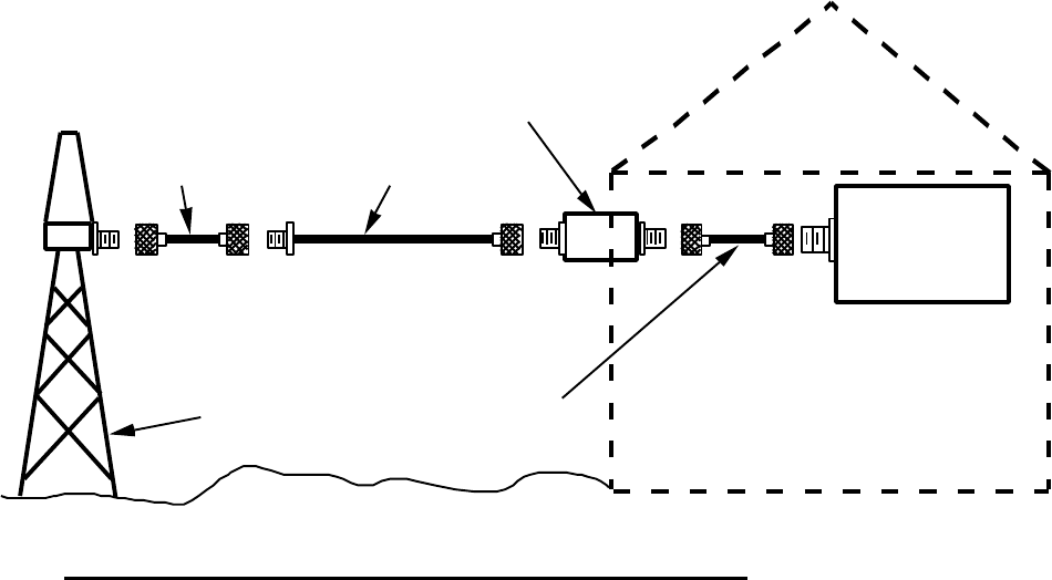
when installed per this manual. A typical terrestrial application is depicted in the Diagram “A”
below.
The Satellite Series Fixed Site Antenna is a helical antenna contained inside a weatherproof housing,
and is intended to be mast mounted without a ground plane of any type. It’s location should be
reasonably clear of nearby metal obstructions and such that a distance of at least 20 cm is
maintained between the antenna and the user. For proper performance in the Iridium system, the
antenna must have a clear view of the sky from the horizon on up and must be mounted vertically.
While horizontal obstructions may not be totally avoidable, they should be minimized, for they may
result in a spot(s) of poor system coverage. This will decrease or possibly eliminate the ability to
operate the Iridium Satellite Series portable phone unit at times which are not predictable by the
user.
The connection between the Satellite Series Fixed Site Antenna and the 9520 Mobile Phone or 9570
Portable Dock is accomplished using specialized coaxial cable system. This cable system is offered
as an option to the Fixed Site Antenna. Alternatively, the user can choose cables from other suitable
sources, following the guidelines outlined further in this manual.
To minimize the loss of radio signal from the antenna to the 9520 Mobile Phone or 9570 Portable
Dock, the coaxial cable system between those two components should be as low loss as possible.
Listed below in Table One are a selection of coaxial cables available from Times Microwave
Fixed
Site
Antenna
8.5 meter
Main Coaxial Cable
High
Frequency
Surge
Suppressor
Antenna
Support
Structure
Satellite Series
Portable Phone
or Portable Dock
0.5 meter
"Jumper"
Coaxial Cable
1.5 meter
"Jumper"
Coaxial Cable
Diagram A--Typical Fixed Antenna and Cable Installation
( Dwelling)
4
(Wallingford, Conneticut, USA. Telephone 203-949-8400). The second cable listed in this table is
part of the optional Satellite Series Antenna Cable kit. The other cables listed are also available
from Times Microwave, and are provided for reference in those applications where longer cable
runs are needed. All cable configurations in Table One are designed to meet Iridium system
requirements.
Table One—Maximum Cable Lengths and Types
Times Microwave
Cable Type Loss
(dB/m) Max.
Length (m) Max.
length (ft)
LMR 240 0.337319 4.5 14.7
LMR 400 0.175363 8.5 28 (Part of Antenna Cable Kit)
LMR 600 0.113623 13.2 44
LMR 900 0.076893 19.7 65
LMR 1200 0.057872 26.2 86
LMR 1700 0.043461 35 115
1.625" LDF 0.036037 42 138.3
2.25" LDF 0.030260 50.2 164.7
Other configurations of cables besides those listed in Table One can be used as long as the total
insertion loss for the entire cable run (including any lighting arrestor/surge suppression) is less than
or equal to 2.5 dB over the operating frequency band of 1616 to 1626 MHz. Consult the chosen
cable manufacturer for more information related to cable performance before installing alternate
cables. A replacement of just the center section of coax specified in the table above must have an
insertion loss less than or equal to 1.52 dB over the operating frequency band of 1616 to 1626
MHz. These insertion loss specifications assumes the use of Satellite Series Fixed Site Antenna.
This antenna meets the antenna gain pattern requirements of the Iridium system.
As depicted in Diagram “A”, the optional Satellite Series Antenna Cable kit consists of three cables
and a lighting arrestor/surge suppressor. Since the main coaxial cable is stiff and difficult to dress,
two more flexible “jumper” cables are provided to connect both ends of the main cable. A small
diameter coax cable 0.5 meter (20 inch) long is provided for a flexible linkage between the antenna
and the main cable. Another 1.5 meter (59 inch) long small diameter coax cable is provided for a
flexible linkage between the 9520 Mobile Phone or 9570 Portable Dock and the main cable. The
lighting arrestor/surge suppressor is installed in series with these cables, as described in Section 8
below.
5
6. Antenna Installation
The Satellite Series Fixed Site antenna is provided with two clamps that allow the attachment of the
antenna housing to the end of a pole/mast with a diameter of between 19 and 25 mm (3/4 to 1
inches). The mast should be secured to a structure such that it can withstand wind loads and other
normal external forces, while being positioned per the guidelines in the Section 5 above. The nuts
on the clamps should be tightened evenly to a torque of 0.45 to 0.68 N-m (4 to 6 in-lbs.). Excessive
torque will result in long term cracking in the plastic mounting bracket.
7. Cable Installation
Cables should be routed and restrained so as to avoid vibration or movement under normal
conditions which could result in damage to either the antenna, the 9520 Mobile Phone or 9570
Portable Dock, or the coaxial cable connections. Where the cables come in contact with structures,
chafing or abrasion of the outer surface of the cable should be prevented. All cable bends must be
done in such a manner as to avoid kinking the cable, and bend radii should follow cable supplier’s
recommended limits. All cable connections must be sealed appropriately to prevent moisture and
corrosion damage due to weather exposure.
When using the optional Satellite Series Antenna Cable kit, cable connections on the three cables in
the cable system employ either Type “N” connectors, or Type “TNC” connectors. Type “N”
connectors should be tightened to a torque of 0.68 to 1.13 N-m (6 to 10 in-lbs.). Type “TNC”
connectors should be tightened to a torque o 0.45 to 0.68 N-m (4 to 6 in-lbs.). When using cables
and connectors from other sources, torque specifications for those connectors should follow those
manufacturers’ recommendations.
8. Lightning Protection
Antennas mounted in fixed installations can be exposed to lightning strikes in certain geographic and
climatological environments. Although it is not considered possible to protect the 9520 Mobile
Phone, the 9570 Portable Dock, the antenna, or surrounding and/or connected equipment or
structures from damage due to a direct lightning strike, appropriate protection should be employed
to minimize equipment and structure damage, and bodily injury due to lightning. Such protection is
typically done through the use of specialized lighting arresting/surge suppression components in the
installation of an antenna system. An example of this is depicted in Diagram “A”.
When using the optional Satellite Series Antenna Cable kit, a high frequency surge suppressor is
supplied with this kit to attempt to minimize lightning induced damage through lighting
arresting/surge suppression. It is intended that this suppressor be installed between either of the
smaller diameter jumper cables and the main coaxial antenna cable. The suppressor should be
installed at the point nearest to where the coaxial cable enters a building structure, or where the
cable first passes close to a grounded structure. Connections to the suppressor should be made in
accordance with the installation instructions supplied by the suppressor manufacturer. If the user
chooses to select antenna cables from an alternate source, a device to deal with lighting
arresting/surge suppression should still be part of the antenna cable system. If there is any
uncertainty as to what might be the appropriate method to use for lightning arresting and surge
protection, the services of a professional antenna installer should be employed.