Motorola Solutions 89FC4821 Non Broadcast Transmitter User Manual Summit BR 800 Tx FCC Filing 3
Motorola Solutions, Inc. Non Broadcast Transmitter Summit BR 800 Tx FCC Filing 3
Exhibit D Users Manual per 2 1033 c3

APPLICANT: MOTOROLA EQUIPMENT TYPE: ABZ89FC4821
EXHIBIT D
User / Operational Manual
Operational or User’s Manual
The manual should include instruction, installation, operator, or technical manuals with required ‘information to the
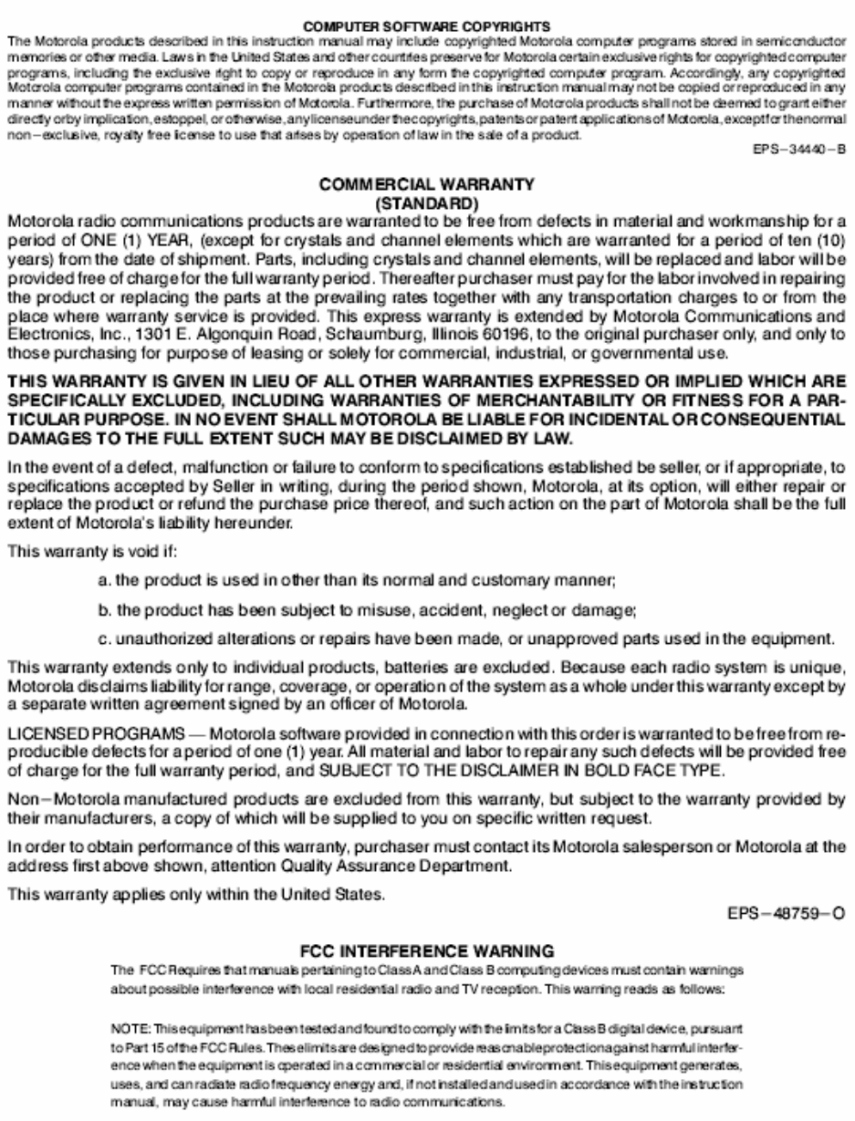
users’. This manual should include a statement that cautions the user that changes or modifications not expressly
approved by the party responsible for compliance could void the user’s authority to operate the equipment. The
manual shall include RF Hazard warning statements, if applicable.
The instruction and service manual for this base radio are not published at this time. However, draft copy of some
of the manual information has been assembled and has been included as part of this filing package.
Upon request, published and/or printed manuals will be sent to the commission and/or telecommunication
certification body (TCB) as soon as they become available. All of the descriptions, block diagrams, and
schematics that are included in this filing package are current as of the package submittal date.
EXHIBIT DESCRIPTION
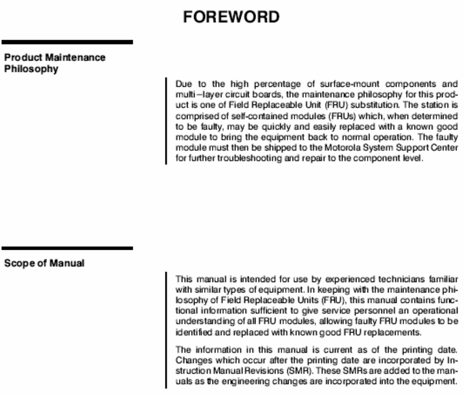
D1-1 Manual Front Matter (Draft)
D1-2 Specifications (Draft)
D1-3 Field Replaceable Units and Orderable Parts (Draft)
D1-4 Tune-Up Procedure
D1-5 Racking Configurations
D1-6 Functional Description / Operation of Modules (Draft)
APPLICANT: MOTOROLA EQUIPMENT TYPE: ABZ89FC4821
EXHIBIT D1-1
User / Operational Manual
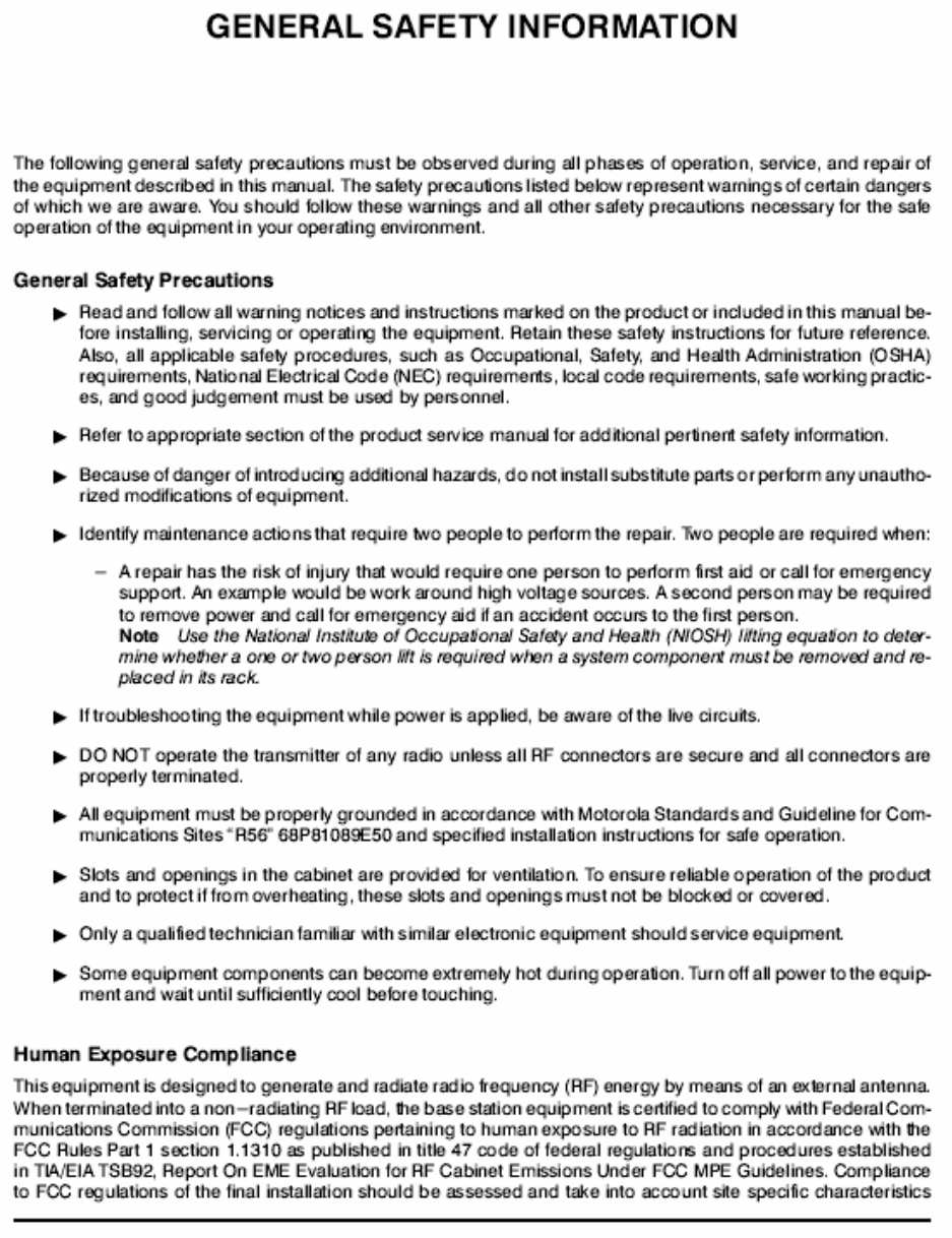
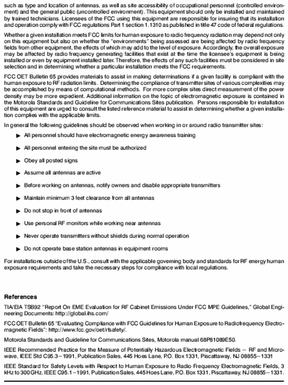
Manual Front Matter (Draft)
APPLICANT: MOTOROLA EQUIPMENT TYPE: ABZ89FC4821
EXHIBIT D1-1
User / Operational Manual
Manual Front Matter (Draft, Continued)
APPLICANT: MOTOROLA EQUIPMENT TYPE: ABZ89FC4821
EXHIBIT D1-1
User / Operational Manual
Manual Front Matter (Draft, Continued)
APPLICANT: MOTOROLA EQUIPMENT TYPE: ABZ89FC4821
EXHIBIT D1-1
User / Operational Manual
Manual Front Matter (Draft, Continued)

APPLICANT: MOTOROLA EQUIPMENT TYPE: ABZ89FC4821
EXHIBIT D1-2
User / Operational Manual
Specifications (Draft)
General Performance
Model T7039
H x W x D 5.25" x 19" x 18" (133x483x457mm)
Weight 46 lbs (21 kg)
Power Requirements
AC: 90-264 VAC, 47-63 Hz
DC: 43-60 VDC
Temperature Range -22 to 140 °F (-30 to 60 °C)
Input / Output Impedance 50 ohms
Antenna Connectors
Transmit: N female
Receive: N female
Modulation
IV&D Transmit / Receive: C4FM, LSM
Frequency Stability External Reference
Channel Spacing
C4FM / LSM: 12.5 kHz
Transmitter
Frequency Range 406.1-435 MHz
Power output
C4FM: 2-110 Watts
LSM: 2-110 Watts (Average)
Electronic Bandwidth Full Bandwidth
Intermodulation Attenuation 40 dB
Spurious and Harmonic Emissions
Attenuation 90 dB
FCC Type Acceptance
FCC Designation: Frequency Range Type Power Output
ABZ89FC4821 406.1-435 MHz Transmitter, C4FM/LSM Variable 2-110 W
ABZ89FR4822 406.1-435 MHz Receiver N/A

APPLICANT: MOTOROLA EQUIPMENT TYPE: ABZ89FC4821
EXHIBIT D1-3
User / Operational Manual
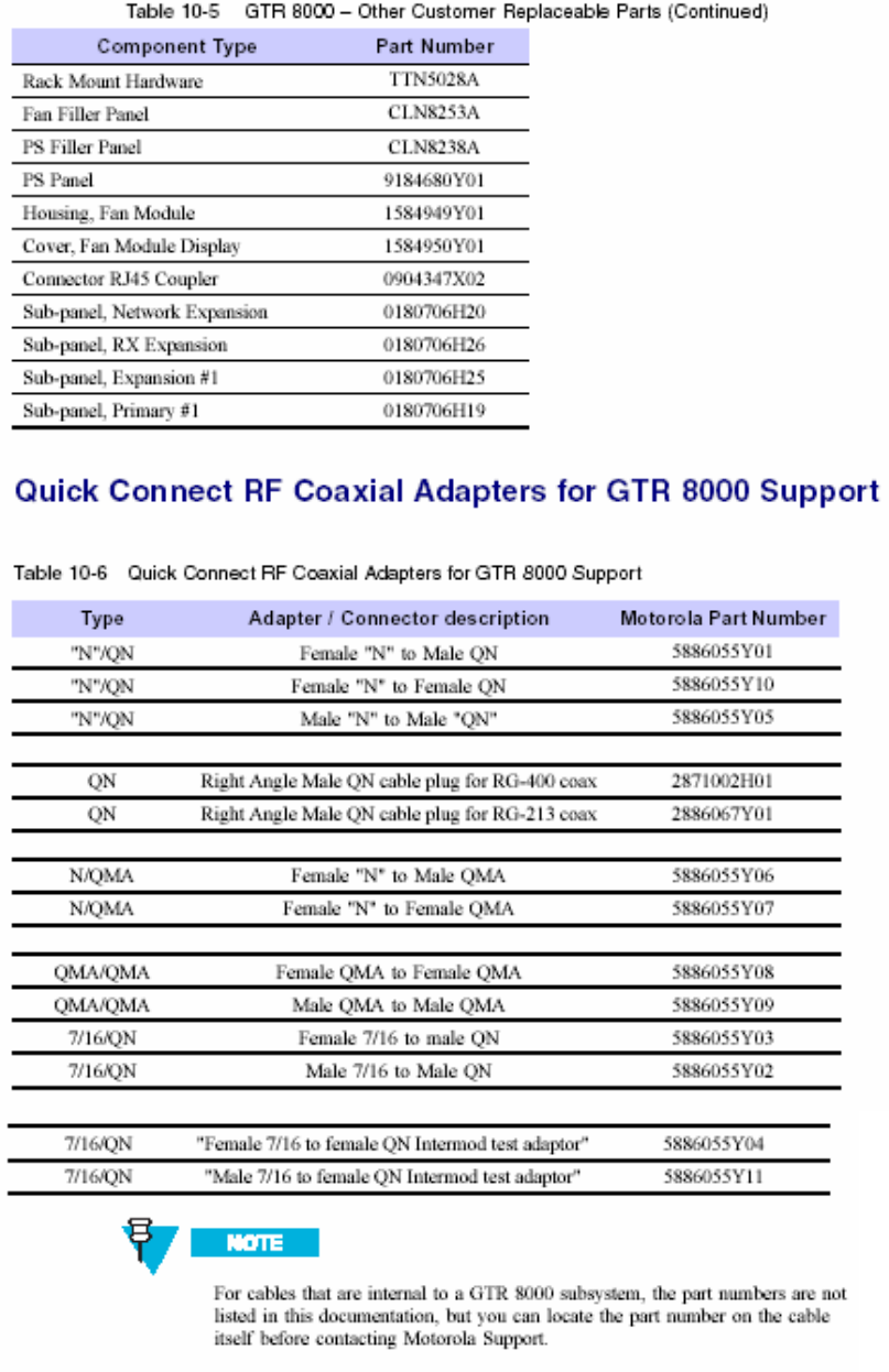
Field Replaceable Units and Orderable Parts (Draft)
Field replaceable units, or FRUs, include special packaging to allow shipment to customers. Parts and
FRUs available for customer order are listed in this section. All parts and FRUs are sourced through the
Radio Products and Service Division (RPSD).
FRU # Description
DLN1396A FRU: PA Mid Power 380-435 MHz
DLN6568A FRU: AC / 48V DC Power Supply
DLN1327A FRU: Power Supply Fan Module
DLN1395A FRU: Transceiver 350-435 MHz
DLN6569A FRU: Site Controller
DLN6636A FRU: Expansion HUB
DLN1380A FRU: Cabinet RMC Pass Through Module
DLN1340A FRU: Receive Multi-Coupler Tray
DLN1338A FRU: Fan Module
DLN1329A FRU: Site Controller Backplane
DLN1330A FRU: Base Radio Backplane
DLN1343A FRU: Expandable Site Subsystem Backplane
DLN1339A FRU: AC Power Distribution Module
Customer Replaceable Power Cables for Standalone Base Radio
Part Number Description
TRN7663A Power Cable, North America
TRN7755A Power Cable, Continental Europe
TTN5049A Power Cable, UK / Ireland
TTN5103A Power Cable, Australia
Other Customer Replaceable Part
Part Number Description
3084827Y01 Battery Temperature Sensor Extension Cable
6484850Y01 Junction Panel (Cabinet Mounting)
6485367Y01 Junction Panel (Rack Mounting)
Other Misc. Hardware
Part Number Description
X153AW Rack Mount Hardware
X882AH 7.5 Ft Open Rack, 48 RU
CA01071AA Inc. UHF Power Monitor Unit 403-435 MHz
X676BG Add External Dual Circulator UHF 380-512 MH
CLE6204A UHF Double Circulator 403-435 MHz
CA01251AA Inc. External Dual Circulator 380-435 MHz
X182BZ Add Duplexer 380-512 MHz
CA01249AA Inc. UHF Duplexer 380-403 MHz
CA01250AA Inc. UHF Duplexer 403-435 MHz
CLE6206A UHF Duplexer 380-403 MHz
CLE6205A UHF Duplexer 403-435 MHz
CA01252AA Inc. Base Radio Preselector 380-435 MHz
X265AP Add Base Radio Preselector 380-512 MHz
APPLICANT: MOTOROLA EQUIPMENT TYPE: ABZ89FC4821
EXHIBIT D1-3
User / Operational Manual
Field Replaceable Units and Orderable Parts (Draft) (Continued)
APPLICANT: MOTOROLA EQUIPMENT TYPE: ABZ89FC4821
EXHIBIT D1-4
User / Operational Manual
Tune-Up Procedure
There is no field tune-up procedure. All adjustments are software controlled and are pre-set at the factory. Certain
station operating parameters can be changed via man-machine interface (MMI) commands, within predetermined
limits. Examples include transmit / receiver operating frequencies and transmitter power level.
APPLICANT: MOTOROLA EQUIPMENT TYPE: ABZ89FC4821
EXHIBIT D1-5
User / Operational Manual
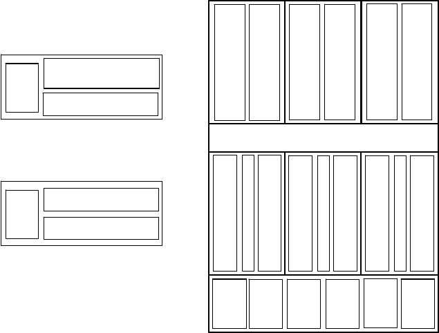
Racking Configurations
There are various equipment racking configurations available to customers. The following section includes
sketches which depict many of the racking alternatives.
GTR 8000 Expandable Site Sub-system Layout
PS #1
PS #2
PS #3
PS #4
PS #5
PS #6
PA #1
PA #2
PA #3
PA #4
PA #5
PA #6
XCVR #1
XCVR #2
XCVR #3
XCVR #4
XCVR #5
XCVR #6
SC #1
SC #2
ALARM
Bay #1 Bay #2 Bay #3
PS #1
PS #2
PS #3
PS #4
PS #5
PS #6
PA #1
PA #2
PA #3
PA #4
PA #5
PA #6
XCVR #1
XCVR #2
XCVR #3
XCVR #4
XCVR #5
XCVR #6
SC #1
SC #2
ALARM
Bay #1 Bay #2 Bay #3
Fan Module #1 serves PA Bay #1
Fan Module #2 serves PA Bay #2
Fan Module #3 serves PA Bay #3
Fan Module #4 serves XCVR Bay #1
Fan Module #5 serves XCVR Bay #2
Fan Module #6 serves XCVR Bay #3
Fan Module #1 serves PA Bay #1
Fan Module #2 serves PA Bay #2
Fan Module #3 serves PA Bay #3
Fan Module #4 serves XCVR Bay #1
Fan Module #5 serves XCVR Bay #2
Fan Module #6 serves XCVR Bay #3
Configuration Layout
PA
XCVR
PS
Base Radio
PA
XCVR
PS
XCVR #2
PS
XCVR #1
XCVR #2XCVR #2
PS
Receive Only Base Radio
GTR 8000 Expandable Site Sub-system Layout
PS #1
PS #2
PS #3
PS #4
PS #5
PS #6
PA #1
PA #2
PA #3
PA #4
PA #5
PA #6
XCVR #1
XCVR #2
XCVR #3
XCVR #4
XCVR #5
XCVR #6
SC #1
SC #2
ALARM
Bay #1 Bay #2 Bay #3
PS #1
PS #2
PS #3
PS #4
PS #5
PS #6
PA #1
PA #2
PA #3
PA #4
PA #5
PA #6
XCVR #1
XCVR #2
XCVR #3
XCVR #4
XCVR #5
XCVR #6
SC #1
SC #2
ALARM
Bay #1 Bay #2 Bay #3
Fan Module #1 serves PA Bay #1
Fan Module #2 serves PA Bay #2
Fan Module #3 serves PA Bay #3
Fan Module #4 serves XCVR Bay #1
Fan Module #5 serves XCVR Bay #2
Fan Module #6 serves XCVR Bay #3
Fan Module #1 serves PA Bay #1
Fan Module #2 serves PA Bay #2
Fan Module #3 serves PA Bay #3
Fan Module #4 serves XCVR Bay #1
Fan Module #5 serves XCVR Bay #2
Fan Module #6 serves XCVR Bay #3
Configuration Layout
PA
XCVR
PS
Base Radio
PA
XCVR
PS
XCVR #2XCVR #2
PS
XCVR #1XCVR #1
XCVR #2XCVR #2
PS
Receive Only Base Radio
APPLICANT: MOTOROLA EQUIPMENT TYPE: ABZ89FC4821
User / Operational Manual
Functional Description / Operation of Modules (Draft)
EXHIBIT D1-6
Transceiver Module Overview
The transceiver (XCVR) module provides receiver, exciter and base radio control functions.
Receiver Overview
The Receiver, which supports three-branch diversity, provides the receiver functions for the Base Radio. The
receiver is a part of the ‘transceiver’ RF board and consists of a front end low noise amplifier section, an on board
pre-selector section, an IF filter section, and a baseband converter section. The receiver Voltage Controlled
Oscillator (VCO) and frequency synthesis circuitry blocks are also part of the receiver section. A digital decoding
section for interface to the control section microprocessor also exists as part of the receiver module.
The receiver interconnects to the control module using an 84-pin flex cable connector. There are no user controls
or indicators on the receiver. For IV&D, only single branch is supported. The receiver also provides enhanced
diagnostic capabilities. This includes receiver sensitivity checking, using on board calibrated noise generator. The
receiver first local oscillator is high side injection.
Exciter Overview
The exciter, in conjunction with the Power Amplifier or PA, provides the transmitter functions for the Base Radio.
The exciter, which is a part of ‘transceiver’ RF board, consists of a baseband circuit block, a baseband modulator
circuit block, a pre-amplifier circuit block, and a final amplifier circuit block. The transmitter Voltage Controlled
Oscillator (VCO) and frequency synthesis circuitry blocks are also part of the exciter. Other functional blocks in the
exciter include the various DC voltage regulators which drive the different circuits, the digital decoding circuitry
block which interfaces the exciter circuits to the microprocessor in the control section, metering capability, and
exciter to receiver loopback capability for diagnostic purposes.
The exciter interconnects to the control module using an 84-pin flex cable connector. There are no user controls or
indicators on the exciter. The exciter uses a Cartesian feedback linearization scheme. The complete Cartesian
feedback loop includes exciter and PA. The exciter includes an internal loop back feature which is used to perform
exciter self diagnostic testing. The exciter also provides controlled output power level to power amplifier.
Control Overview
The Transceiver Control circuitry performs the control management, digital signal processing, and transmit and
receive data formatting for the base radio (BR). The Host Processor is a Freescale MPC8250 and the main DSP
is a Freescale MSC8101. A second DSP is a Texas Instrument device (TMS320VC5502) and is used for Block
Encoding/Decoding. It also provides the various external interfaces described below.
APPLICANT: MOTOROLA EQUIPMENT TYPE: ABZ89FC4821
User / Operational Manual
Functional Description / Operation of Modules (Draft)
EXHIBIT D1-6
The main operating software for the base radio is loaded in the transceiver’s control section. As the main manager
for the base radio, the XCVR control board provides operational control over the other station modules. It handles
three types of information flow, in the following ways:
• Serves as a gateway between the network and RF functionality, by distributing the RF payload to and from
the network
• Supports operational and diagnostic functions with digital control data (for example: site information,
channel assignments, and identification numbers for call processing)
• Ensures the flow of other network management configuration information
The External interfaces include three Ethernet ports per Transceiver. Two of the Ethernet ports on the Transceiver
are used to communicate with the site controller. On single base radios these two Ethernet ports go to RJ45
connectors on the backplane. In the GTR 8000 Expandable Site Subsystem the site controller and transceiver
connect directly via the backplane. These two Ethernet interfaces also contain TDM signals which are used to
pass time reference, frequency reference and control data to the station. The third Ethernet port is located on the
front panel of the Transceiver and is used as a Dedicated CSS Port. A RS232 port also resides on the front panel
and is also used as a Dedicated CSS Port.
Additional connections located behind the Fan Module are an asynchronous port, a synchronous port, and an
alignment reference port. The synchronous port is used for V.24 application.
Inter-module communication is achieved using a Serial Peripheral Interface (SPI) bus. The SPI bus allows
communication with the slave devices consisting of the Power Supply, Receiver, Exciter and Power Amplifier
modules.
The Transceiver generates the station frequency reference which needs to be locked to one of many possible
external sources of various frequencies. The external sources can be one of the site controller 20 MHz TDM
clocks or an external reference operating at 5 or 10 MHz or 5 MHz/1pps composite signal.
Status Indicators and Buttons
There is one button on the Front Panel of the GTR 8000 Transceiver Module. This multifunction button can be
used to reset the module or to place the transceiver in an access disable mode.
The number and color scheme of the LEDs is application specific. The LEDs indicate the following states: Online,
Failure, Impaired, Booting, Lamp Test, Receiver Inhibited, Receiver Active, Illegal Carrier, Control Channel
(Operating), Control Channel (Failsoft), Service Mode, Transmitter Inhibited, Infrastructure Line Connected,

APPLICANT: MOTOROLA EQUIPMENT TYPE: ABZ89FC4821
User / Operational Manual
Functional Description / Operation of Modules (Draft)
EXHIBIT D1-6
Infrastructure Link Disconnected, Software Download, VLAN, Detection, VLAN Split, Warning, Minor Hardware
Failure, Major Hardware Failure, Critical Hardware Failure, Ethernet link status.
Front Panel RS-232 / Ethernet (DB9) / RJ45 Interface
The Front Panel port supports 2-wire RS-232 on a DB9 connector and 10/100BaseT Ethernet on a RJ45
connector. See tables below for connector pinout.
Only the TXD and RXD signals are supported, no other handshake signals are provided. The table below shows
the signals supported along with the Host hardware resource responsible the RS232 signals.
The front panel also supports a 10/100BaseT Ethernet port. The connector is configured and an MDI-X port that
can be connected to a laptop using a standard cable. In essence, the transmit and receive signal pairs are
reversed on the BRC front panel compared to that defined in IEEE Std. 802.3 Clause 14.5.1. The Ethernet PHY is
a Broadcom BCM5221. Its address (4:0) is '00100'. Both the Front Panel Ethernet PHYand the CP2 PHY
(BCM5222) communicate to the Host via the "bit -banged" GPIO MDC and MDIO signals.
Front Panel Port Signals
RJ45 Pin # RS-232 Signal
1 RD+ (Ethernet)
2 RD- (Ethernet)
3 TD+ (Ethernet)
4 NC
5 NC
6 TD- (Ethernet)
7 NC
8 NC
Front Panel RS232 Cable Adapter
RJ45 Pin # RS232 DB9 / Female
1 NC
2 TXD (RS232) (Host PA9)
3 RXD (RS232) (Host PA8)
4 NC
5 GND
6 Ext_Trigger_In (DSP IRQ1)
7 NC
8 GND
9 Ext_Trigger_Out (DSP PA20)
Power Amplifier Module Overview
The GTR 8000 Power Amplifier (PA) is a hot-swap capable, forced convection cooled RF power amplifier. It
accepts a low-level modulated RF signal from the transceiver module, and amplifies it for transmission via the site
transmit antenna. Also, to complete the Cartesian correction loop (GTR 8000’s linearization method), it provides a
low level RF feedback signal to the transceiver module to achieve the required transmitter linearity. The power
amplifier consists of the several sub-circuits and boards including core, driver, final, isolator, low pass filter, power
converter and distribution.
APPLICANT: MOTOROLA EQUIPMENT TYPE: ABZ89FC4821
User / Operational Manual
Functional Description / Operation of Modules (Draft)
EXHIBIT D1-6
There are three electrical connection assemblies on the PA:
• Power supply/communications connector (backplane connection)
• RF input/feedback connector (backplane connection)
• RF output connector (front “quick-N” or QN connection)
The PA is secured to the card cage with 2 TORX screws (T20 bit size required).
The PA has 3 front panel LED indicators that work in concert with each other. Their meaning is as follows when
the BR is powered:
1) PA TRANSMIT LED (Bi-Colored):
- RED LIGHT indicates that the PA is transmitting at less than full requested power
- GREEN LIGHT indicates that the PA is transmitting at full requested output power
- NO LIGHT indicates that the PA is not in a transmitting state
2) PA STATUS LED:
- GREEN LIGHT (on) indicates the PA is functioning normally
- GREEN LIGHT (off) indicates a PA failure
- GREEN LIGHT (blinking) the base radio is booting
3) PA ALARM LED:
- RED LIGHT (on) indicates a PA failure
- RED LIGHT (off) indicates that the PA is functioning normally
- RED LIGHT (blinking) the PA is impaired
The power amplifier (PA) module is a forced convection cooled RF power amplifier that operates to the following
electrical performance specifications:
- Maximum Rated Average Power Out: 110 Watt
- Rated Peak Power Out: 200 Watt
- Minimum Rated Average Power Out: 2 Watt
- Nominal RF Gain: 42 dB
- Nominal Input Supply Voltage: 29 Volts DC
- Maximum Modulation Bandwidth: 25 kHz
- Operational Frequency Range: 380 MHz to 435 MHz
APPLICANT: MOTOROLA EQUIPMENT TYPE: ABZ89FC4821
User / Operational Manual
Functional Description / Operation of Modules (Draft)
EXHIBIT D1-6
The Power Amplifier is comprised of six internal modules. These are described briefly in the following paragraphs.
1. The Core Board provides the following functionality:
- Routes DC to the Converter and Driver Boards
- Routes RF to the Driver Board
- Provides gain and FB power control
- Provides for diagnostic sensors
- Provides for intermediate voltages used by itself and other modules in the PA
- Provides the PA’s digital interface to the rest of the Base Radio
- Provides for cooling measures control
- Provides for control of subordinate modules
2. The Power Converter Board provides the following functionality:
- Provides 29 Volts DC and an intermediate voltage to the Distribution Board
3. The Driver Amplifier Board provides the following functionality:
- Provides the first RF gain stage of the PA
- Provides supporting bias circuits for the Driver Amplifier
4. The Final Amplifier Board provides the following functionality:
- Provides the second RF gain stage of the PA (parallel stage)
- Provides supporting bias circuits for the Final Amplifier
- Provides for RF power splitting
- Provides for RF power combining
- Provides diagnostics
5. The Distribution Board provides the following functionality:
- Provides for RF routing from the Driver Amplifier to the Final Amplifier
- Provides for RF routing from the Final Amplifier to the Output Module
- Provides for DC power routing from the Core Board to the Output Module
- Provides for DC power routing from the Power Converter Board to the Final Amplifier
- Provides for Forward and Reverse Power routing from the Output Module to the Core Board
- Provides for feedback power coupling to the Core Board
- Routes module control from the Core Board to the Final Module
- Routes diagnostics from the Final Module to the Core Board
6. The Output Module provides the following functionality:
- Provides output isolation to the PA
- Provides for harmonic attenuation
- Provides for forward and reverse power detection
Power Supply Module Overview
The power supply module operates from either an AC or DC input and provides the DC operating voltages for the
other Base Radio modules. These modules are sometimes also referred to as field replaceable units (FRU).
When operating from an AC source (90 to 264 VAC, 47 to 63 Hz), the supply generates two DC output voltages of
28.94 Volts with reference to output ground. The power supply automatically adjusts to AC input ranges and
supplies a steady output. In AC mode, the power supply contains a separate battery charger which can be used to
maintain the charge on a 48 Volt DC nominal system, positive or negative ground (if installed).
APPLICANT: MOTOROLA EQUIPMENT TYPE: ABZ89FC4821
User / Operational Manual
Functional Description / Operation of Modules (Draft)
EXHIBIT D1-6
When operating from a DC source (43.2 VDC to 60 VDC, positive or negative ground), the supply generates two
DC output voltages of 28.94 Volts with reference to output ground. The battery charger is not useable when
operating from a DC input power source.
When both AC and DC sources are available, the power supply operates from the AC source. When the AC
source is lost, the power supply automatically shifts to DC operating mode. When the AC source is restored, the
power supply automatically shifts to AC operating mode. Output is not interrupted when switching between AC
and DC sources.
The power supply contains several switching-type power supply circuits, power factor correction circuitry, battery
charging circuitry, diagnostics and monitoring circuitry.
The power supply module interconnects to the chassis backplane using a multi-pin power connector. Two Torx
screws on the front panel of the power supply module secure it in the chassis.
Power Supply Controls and Indicators
The power supply module has three front panel light emitting diode (LED) indicators:
1) ALARM: a RED LED that when illuminated indicates the power supply is no longer operating within its
design specifications
2) STATUS: a GREEN LED that when illuminated indicates the power supply is operating within its design
specifications
3) FAN: a RED LED that when illuminated indicates the power supply fan is no longer functioning per its
design specifications.
The front panel ON/OFF switch is used to enable or disable the DC outputs of the power supply module.
APPLICANT: MOTOROLA EQUIPMENT TYPE: ABZ89FC4821
User / Operational Manual
Functional Description / Operation of Modules (Draft)
EXHIBIT D1-6
Power Supply Performance Specifications
Operating Temperature: -30 to +60 °C
Input Voltage: AC: 90 to 264 Volts AC
DC: 43.2 to 60 Volts DC
Input Frequency Range (AC operation): 47 to 63 Hz
Input Current: AC: 10 Amps Maximum (120 VAC), 5 Amps Max (220/240 VAC)
DC: 18A maximum
Steady-State Output Voltage:
Main DC Output: 28.94 Volts DC +/- 2.7%
Aux DC Output: 28.94 Volts DC +/- 3.0%
Total Output Power Rating:
DC Outputs: 600 Watts
Battery Charger: 150 Watts
Battery Charger Output Voltage Range: 45 to 58 Volts DC
Battery Charger Output Current: 3 Amps maximum
Output Ripple: All outputs 50 mV p-p
(measured with 20 MHz BW oscilloscope at 25°C)
Short Circuit Current: 0.5 Amp average (maximum)