Motorola Solutions 89FC5763-A Non-Broadcast Transmitter User Manual EBRC LNODCT Tx FCC Filing
Motorola Solutions, Inc. Non-Broadcast Transmitter EBRC LNODCT Tx FCC Filing
UserManual.wiki
>
Motorola Solutions
>
89FC5763 A User Manual
Exhibit D Users Manual per 2 1033 c3
Navigation menu
Upload a User Manual
Namespaces
Wiki Guide
HTML
PDF
Info
Views
User Manual
Discussion / Help
Navigation
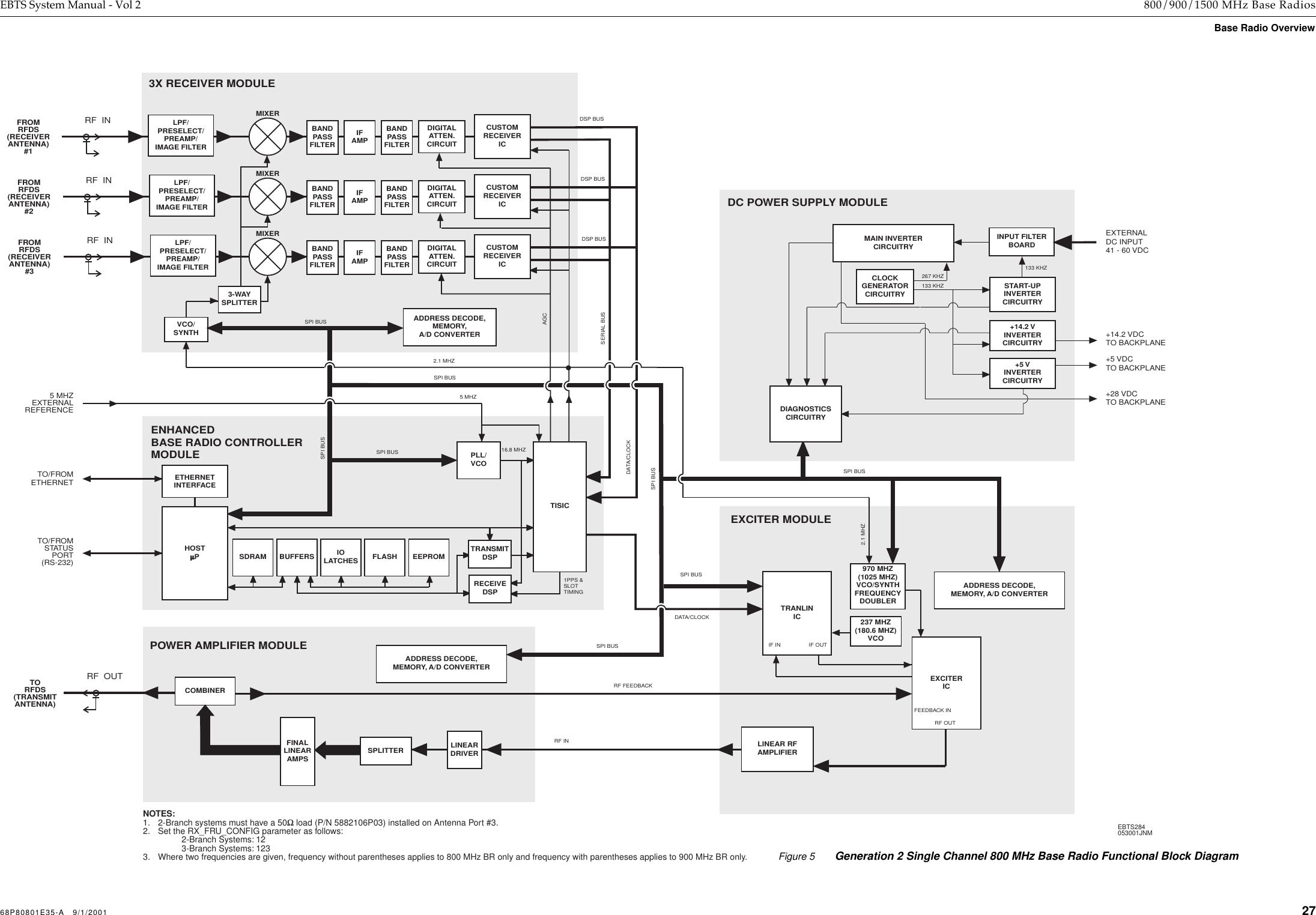
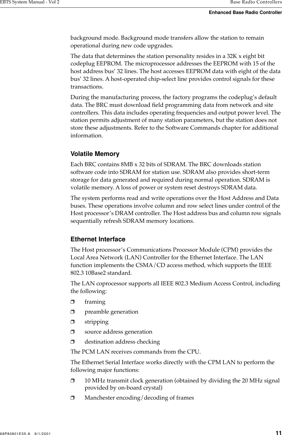
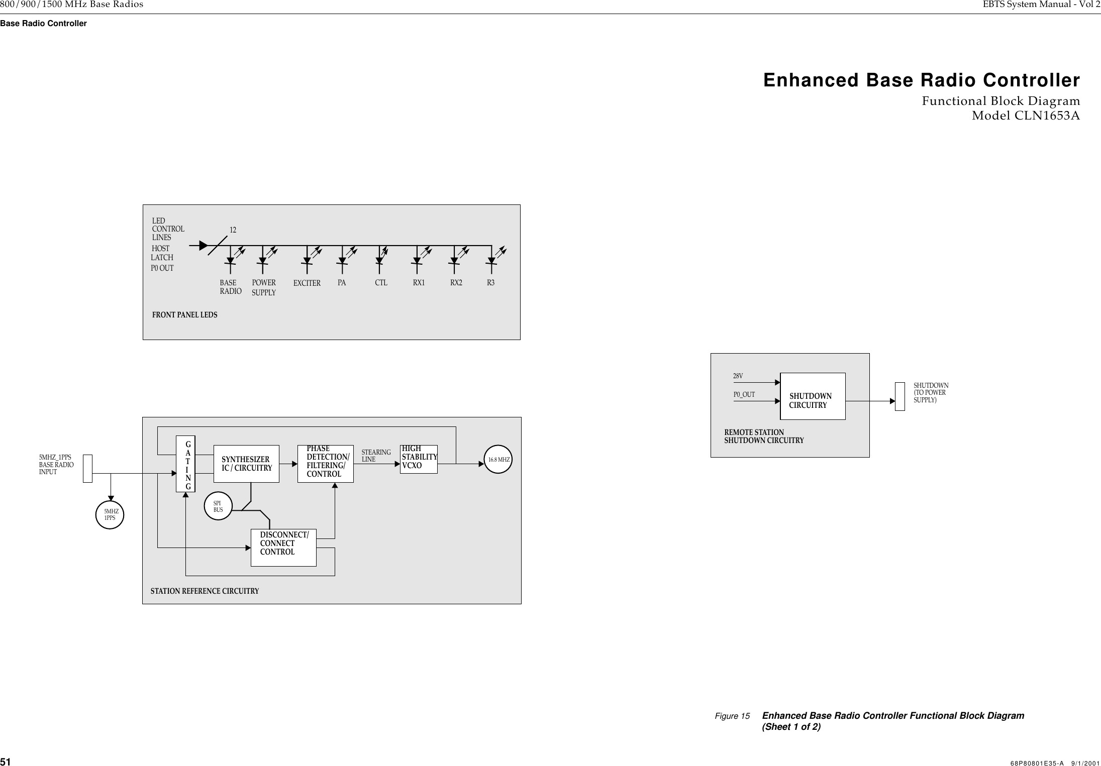
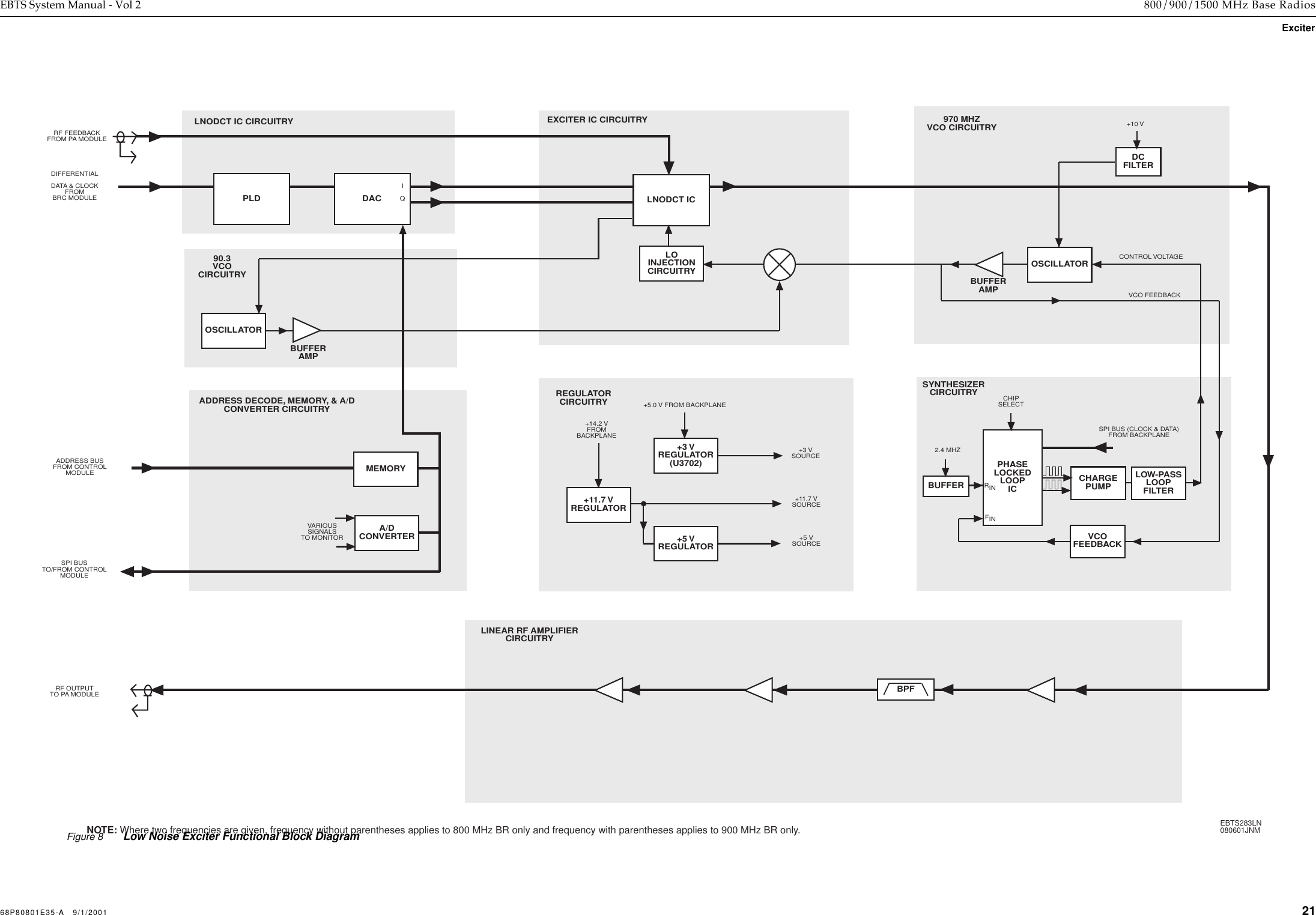
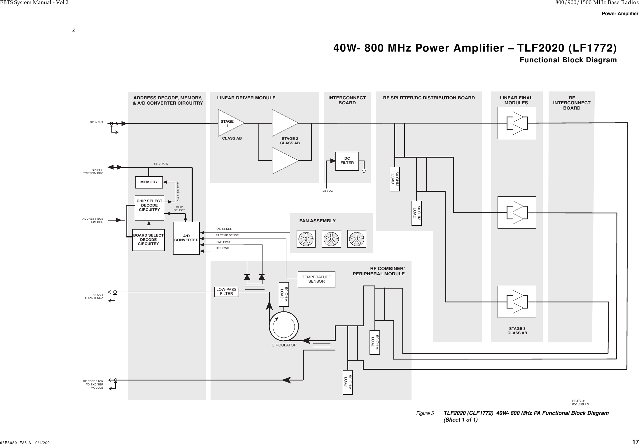
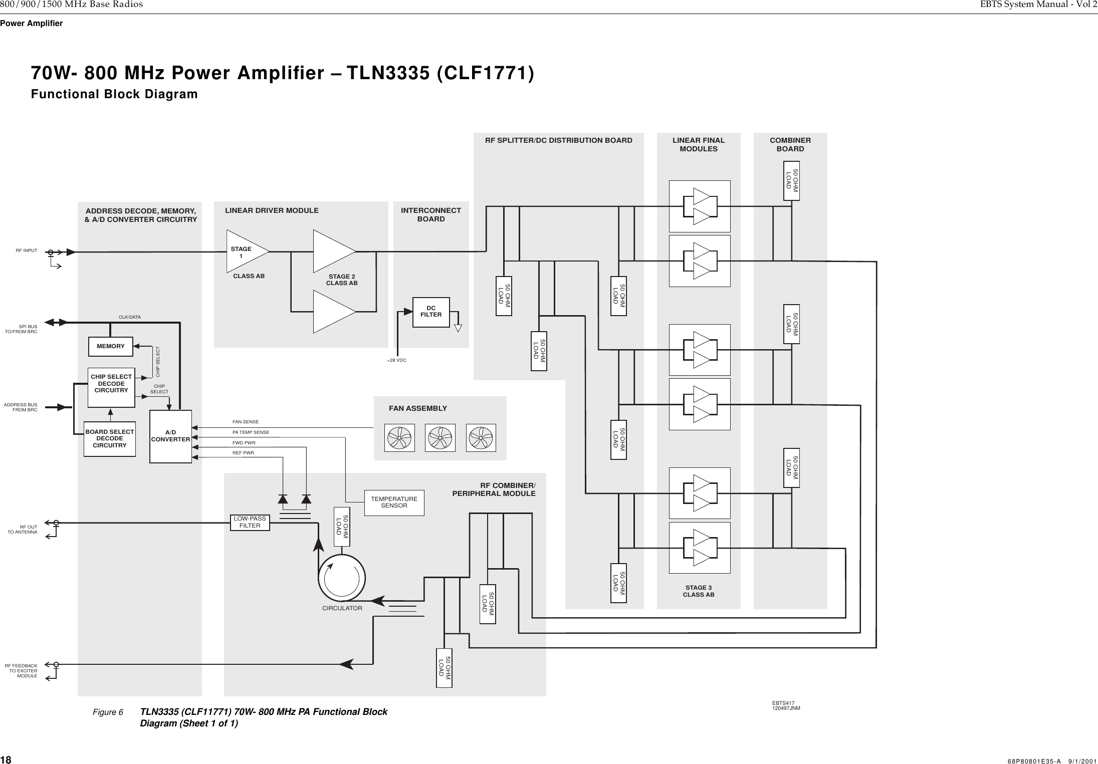
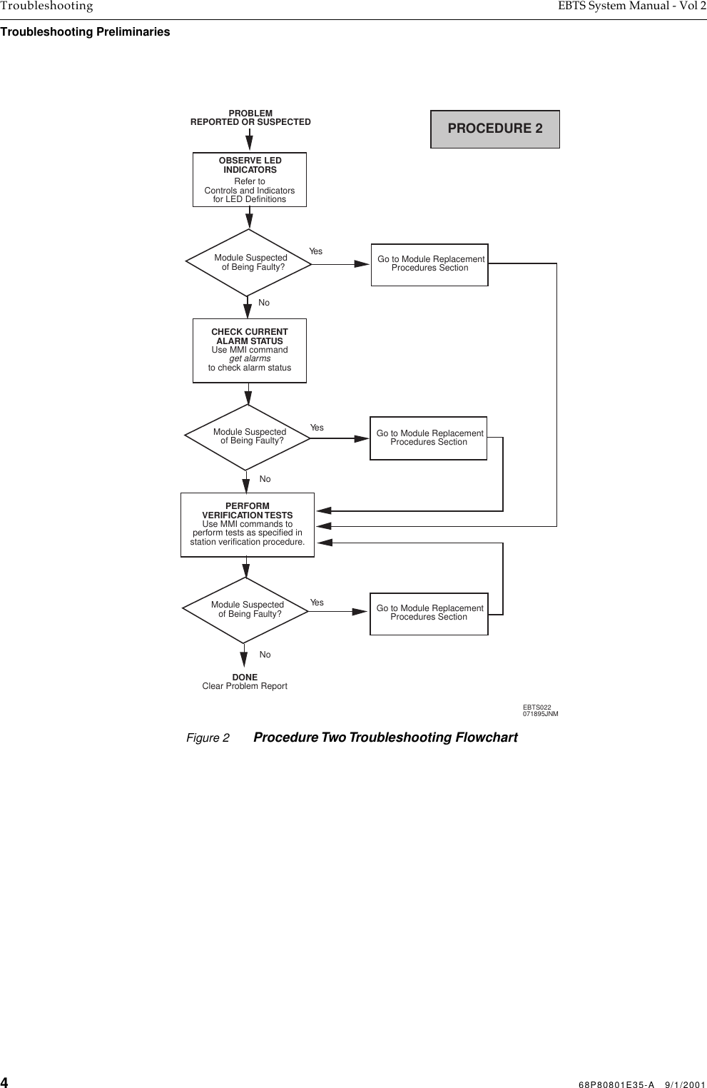
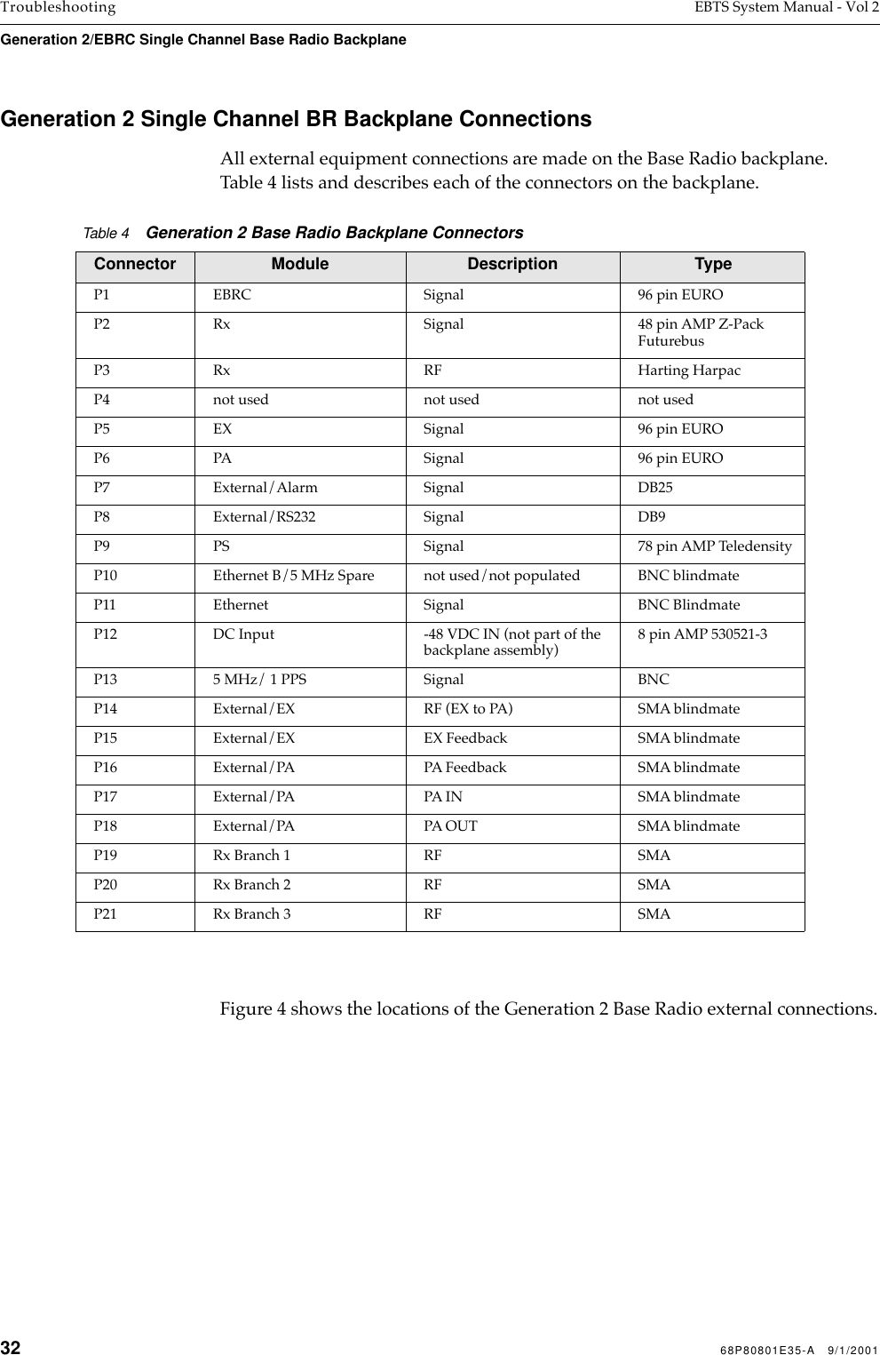
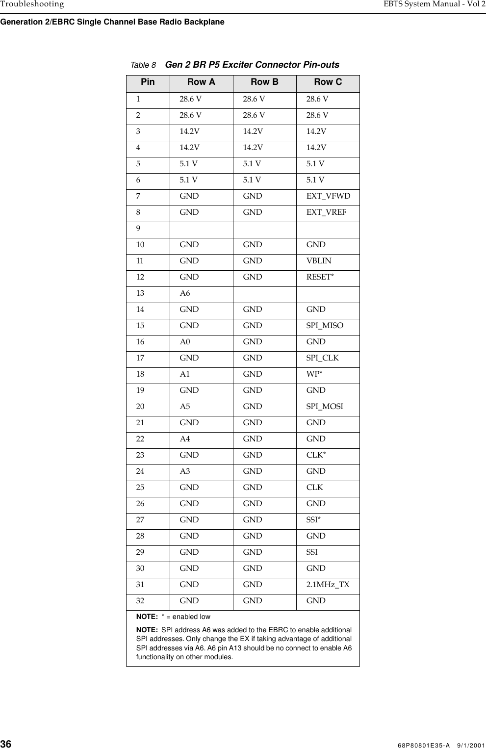
![52 68P80801E35-A 9/1/2001 800/900/1500 MHz Base Radios EBTS System Manual - Vol 2Base Radio Controller Figure 16 Enhanced Base Radio Controller Functional Block Diagram (Sheet 2 of 2)EnhancedBase Radio ControllerFunctional Block DiagramModel CLN1653AHOSTMICRO-ETHERNETSERIALINTERFACETRANS-CDRCV RXTRMT TXCLSN10BASE2COAXETHERNETSERIALINTERFACECEIVERISOLATIONTRANSFORMERPROCESSORSCC18SDRAM4M x 16SDRAM4M x 16SDRAM4M x 16SDRAM4M x 16GPLA0, A[8,9,17,18,20:29],RAS,CAS,WECS2CS3D[0:31]D[0:15]D[16:31]D[0:15]D[16:31]BUFFERBUFFERBUFFERBUFFERBUFFERBUFFERD[0:31]D[0:7]A[10:31]MA[21:0]DSP_D[31:24]A[0:7]DSP_A[31:24]MD[31:0]EIA-232BUSRECEIVERS/DRIVERS2STATUS PORT(9 PIN D CONNECTORON BRC FRONT PANEL)2BUFFER33SPI BUS TO/FROM STATION MODULESFLASH1M x 16FLASH1M x 16FLASH1M x 16FLASH1M x 16CS0CS1MD[0:15]MD[16:31]MD[0:15]MD[16:31]1616161616 161616MA[2:21]MA[2:21]EEPROM32k x 8MD[24:31]MA[0:14]CS4P1_OUTLATCHP0_OUTLATCHMD[0:32]MD[24:31]P0_INBUFFERMD[16,17,20-24,28-31]STATUS BUSFROMSTATION MODULESP0_IN8CONTROL BUSTOSTATION MODULESP0_OUT/P1_OUT328TRANSMITDIGITALSIGNALPROCESSOR(TX DSP)SINGLE ENDTO DIFFERENTIALSERIAL DATA ANDCLOCK TO EXCITERDIFFERENTIALTO SINGLE ENDRX1 SERIAL DATARECEIVEDIGITALSIGNALPROCESSOR(RX DSP 1)TISICA[0:5]D[0, 8:23]D[0, 23]SERIAL CONTROL DATATO RECEIVER 12.1 MHz1 PPS TIMING, CONTROL/ SLOT TIMING/RESETNETWORKEDSCI16.8MHZSPIBUSDIGITAL SIGNAL PROCESSING CIRCUITRYDIFFERENTIALTO SINGLE ENDDIFFERENTIALTO SINGLE END50 MHZCLOCKFRONT PANELRESETDRAM MEMORYETHERNET INTERFACENON-VOLATILE MEMORY EXPANDED STATUS INPUTAND OUTPUT CONTROL CIRCUITRYEXTENDED HOSTBUS BUFFERS40TO EXCITER5MHZ1PPSRX2 SERIAL DATARX3 SERIAL DATAHOST ADDRESS BUSHOST DATA BUSHOST BUFFERED DATA BUSHOST BUFFERED ADDRESS BUSHOST-DSP BUFFERED DATA BUSHOST-DSP BUFFERED ADDRESS BUSSERIAL MANAGEMENT CONTROLLER (SMC2)SERIAL PERIPHERAL INTERFACEAND RECEIVERSSERIAL CONTROL DATATO RECEIVER 2SERIAL CONTROL DATATO RECEIVER 3BUFFER/SPLITTERTRANSMITSERIALDATA BUS 3AGC4DATA CLOCK 2DATA CLOCK 1DATA CLOCK 3 AGC TOALL RECEIVERS](https://usermanual.wiki/Motorola-Solutions/89FC5763-A/User-Guide-181509-Page-49.png)