Motorola Solutions 89FC5775-D Non-Broadcast Transmitter User Manual
Motorola Solutions, Inc. Non-Broadcast Transmitter
Exhibit D Users Manual per 2 1033 c3

APPLICANT: MOTOROLA INC. EQUIPMENT TYPE: ABZ89FC5775-D
EXHIBIT 8
INSTRUCTION MANUALS
Draft copy of the of the front matter of the following instruction manual is enclosed with this submission:
68P81095E55-C ......................................................................... Quantar Digital Capable Station
For Conventional, ASTRO
6809 Trunking, and IntelliRepeater Systems
Instruction Manual
Other system and radio / configuration service software manuals are available to support the product and system
in operation. They can be provided to the Commission upon request.

APPLICANT: MOTOROLA INC. EQUIPMENT TYPE: ABZ89FC5775-D
EXHIBIT 9
TUNE-UP PROCEDURE
This exhibit contains the tune-up procedure as it will appear in the Configuration Service Software (CSS) manual.
The following adjustments comprise the total transmitter alignment:
1. Reference Oscillator
2. Transmitter Power Output
3. Transmit Deviation Control
4. Reference Modulation Compensation
Note: All adjustments are factory pre-set and do not require alignment under normal operating conditions. In the
event alignment is needed, refer servicing to qualified radio maintenance personnel only.
TEST EQUIPMENT
Description Recommended model
1. Service Monitor Motorola R-2001 or equivalent
2. PC with CSS
TRANSMITTER ALIGNMENT PROCEDURE
CSS/RSS Port: A 9-pin D connector is provided on the station control module front panel to allow service
personnel to connect a PC loaded with the Configuration Service Software (CSS) and perform programming and
maintenance tasks via this TIA RS-232 port. The following pages of this exhibit will show the important alignment
screens.
EXHIBIT DESCRIPTION
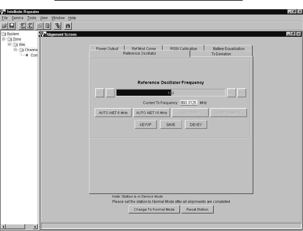
9A Reference Oscillator Alignment Screen
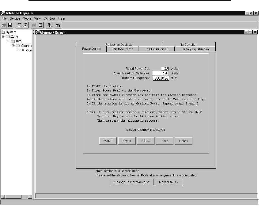
9B Transmitter Power Output Alignment Screen
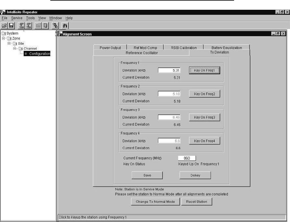
9C Transmitter Deviation Alignment Screen
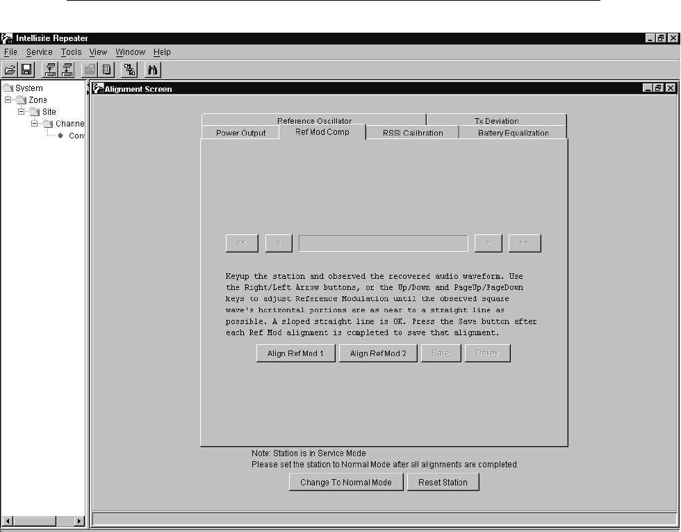
9D Reference Modulation Compensation Alignment Screen
All adjustments are software controlled and are pre-set at the factory. Certain station operating parameters can be
changed via man-machine interface (MMI) commands, within predetermined limits. Examples include transmit /
receiver operating frequencies and power level.
APPLICANT: MOTOROLA INC. EQUIPMENT TYPE: ABZ89FC5775-D
EXHIBIT 9A
TUNE-UP PROCEDURE - Reference Oscillator Alignment Screen
APPLICANT: MOTOROLA INC. EQUIPMENT TYPE: ABZ89FC5775-D
EXHIBIT 9B
TUNE-UP PROCEDURE - Transmitter Power Output Alignment Screen
APPLICANT: MOTOROLA INC. EQUIPMENT TYPE: ABZ89FC5775-D
EXHIBIT 9C
TUNE-UP PROCEDURE - Transmitter Deviation Alignment Screen
APPLICANT: MOTOROLA INC. EQUIPMENT TYPE: ABZ89FC5775-D
EXHIBIT 9D
TUNE-UP PROCEDURE - Reference Modulation Compensation Alignment Screen
Instruction Manual
68P81095E05-C
TM
Digital-Capable Station
For Conventional, ASTRO,
6809 Trunking, and IntelliRepeater Systems
VHF Ċ 25W & 125W
UHF Ċ 25W, 100W, & 110W
800 MHz Ċ 20W & 100W
900 MHz Ċ 100W
PRELIMINARY

COMPUTER SOFTWARE COPYRIGHTS
The Motorola products described in this instruction manual may include copyrighted Motorola computer programs stored in semiconductor
memories or other media. Laws in the United States and other countries preserve for Motorola certain exclusive rights for copyrighted computer
programs, including the exclusive right to copy or reproduce in any form the copyrighted computer program. Accordingly, any copyrighted
Motorola computer programs contained in the Motorola products described in this instruction manual may not be copied or reproduced in any
manner without the express written permission of Motorola. Furthermore, the purchase of Motorola products shall not be deemed to grant either
directly or by implication, estoppel, or otherwise, any license under the copyrights, patents or patent applications of Motorola, except for the normal
non-exclusive, royalty free license to use that arises by operation of law in the sale of a product.
EPS-34440-B
COMMERCIAL WARRANTY
(STANDARD)
Motorola radio communications products are warranted to be free from defects in material and workmanship for a
period of ONE (1) YEAR, (except for crystals and channel elements which are warranted for a period of ten (10)
years) from the date of shipment. Parts, including crystals and channel elements, will be replaced and labor will be
provided free of charge for the full warranty period. Thereafter purchaser must pay for the labor involved in repairing
the product or replacing the parts at the prevailing rates together with any transportation charges to or from the
place where warranty service is provided. This express warranty is extended by Motorola Communications and
Electronics, Inc., 1301 E. Algonquin Road, Schaumburg, Illinois 60196, to the original purchaser only, and only to
those purchasing for purpose of leasing or solely for commercial, industrial, or governmental use.
THIS WARRANTY IS GIVEN IN LIEU OF ALL OTHER WARRANTIES EXPRESSED OR IMPLIED WHICH ARE
SPECIFICALLY EXCLUDED, INCLUDING WARRANTIES OF MERCHANTABILITY OR FITNESS FOR A PARĆ
TICULAR PURPOSE. IN NO EVENT SHALL MOTOROLA BE LIABLE FOR INCIDENTAL OR CONSEQUENTIAL
DAMAGES TO THE FULL EXTENT SUCH MAY BE DISCLAIMED BY LAW.
In the event of a defect, malfunction or failure to conform to specifications established be seller, or if appropriate, to
specifications accepted by Seller in writing, during the period shown, Motorola, at its option, will either repair or
replace the product or refund the purchase price thereof, and such action on the part of Motorola shall be the full
extent of Motorola's liability hereunder.
This warranty is void if:
a. the product is used in other than its normal and customary manner;
b. the product has been subject to misuse, accident, neglect or damage;
c. unauthorized alterations or repairs have been made, or unapproved parts used in the equipment.
This warranty extends only to individual products, batteries are excluded. Because each radio system is unique,
Motorola disclaims liability for range, coverage, or operation of the system as a whole under this warranty except by
a separate written agreement signed by an officer of Motorola.
LICENSED PROGRAMS Ċ Motorola software provided in connection with this order is warranted to be free from reĆ
producible defects for a period of one (1) year. All material and labor to repair any such defects will be provided free
of charge for the full warranty period, and SUBJECT TO THE DISCLAIMER IN BOLD FACE TYPE.
Non-Motorola manufactured products are excluded from this warranty, but subject to the warranty provided by
their manufacturers, a copy of which will be supplied to you on specific written request.
In order to obtain performance of this warranty, purchaser must contact its Motorola salesperson or Motorola at the
address first above shown, attention Quality Assurance Department.
This warranty applies only within the United States.
EPS-48759-O
FCC INTERFERENCE WARNING
The FCC Requires that manuals pertaining to Class A and Class B computing devices must contain warnings
about possible interference with local residential radio and TV reception. This warning reads as follows:
NOTE: This equipment has been tested and found to comply with the limits for a Class B digital device, pursuant
to Part 15 of the FCC Rules. These limits are designed to provide reasonable protection against harmful interferĆ
ence when the equipment is operated in a commercial or residential environment. This equipment generates,
uses, and can radiate radio frequency energy and, if not installed and used in accordance with the instruction
manual, may cause harmful interference to radio communications.

EMotorola, Inc. 2002
All Rights Reserved
Printed in U.S.A.
68P81095E05-C
8/30/02-UP
Commercial Government and
Industrial Solutions Sector
1301 E. Algonquin Road, Schaumburg, IL 60196
t
Digital-Capable Station
for Conventional, ASTRO,
6809 Trunking, and IntelliRepeater Systems
VHF Ċ 25W & 125W
UHF Ċ 25W, 100W, & 110W
800 MHz Ċ 20W & 100W
900 MHz Ċ 100W
Commercial Government and
Industrial Solutions Sector
Table of Contents
Model/Option Information xi....................................................................
Foreword xxiv...............................................................................
General Safety Information xxvi.................................................................
Performance Specifications xxviii................................................................
DESCRIPTION
DESCRIPTION 68P81096E56.........................................................
Introduction page 1...................................................................
Compact Mechanical Design page 1............................................................
StateĆofĆtheĆArt Electrical Design page 2.........................................................
Summary of Operating Features page 3.........................................................
Multiple System Capability page 4..............................................................
Station Components page 6...........................................................
Functional Theory of Operation page 8.................................................
Transmitter Circuitry Operation page 8..........................................................
Receiver Circuitry Operation page 9.............................................................
Station Control Circuitry Operation page 9.......................................................
Wireline Interface Board Operation page 10.....................................................
Power Supply Module Operation page 10.......................................................
INSTALLATION
INSTALLATION 68P81096E57........................................................
Pre-Installation Considerations page 2................................................
Installation Overview page 2...................................................................
Environmental Conditions at Intended Site page 3................................................
Equipment Ventilation page 3..................................................................
AC Input Power Requirements page 4...........................................................
Equipment Mounting Methods page 4...........................................................
Site Grounding and Lightning Protection page 5..................................................
Recommended Tools and Equipment page 6.....................................................
Equipment Unpacking and Inspection page 6....................................................
Physical Dimensions and Clearances page 7.....................................................
Ċcontinued on next page Ċ

ii 8/30/0268P81095E05-C
Mechanical Installation page 14........................................................
Unpacking the Equipment page 14............................................................
Mounting Procedures page 20................................................................
Stacking Cabinets page 25...................................................................
Stacking Modular Racks page 26..............................................................
Anti-Vibration/EMI Screws page 27............................................................
Electrical Connections page 28........................................................
Power Supply Connections page 28...........................................................
RF Cabling Connections page 32..............................................................
Connecting System Cables page 38...........................................................
Connecting Telephone Lines page 46..........................................................
Connecting V.24 Modems page 50.............................................................
Connecting External Reference page 51........................................................
Post-Installation Checkout page 54....................................................
Applying Power page 54......................................................................
Verifying Proper Operation page 54............................................................
Proceeding to Optimization page 56...........................................................
OPTIMIZATION
OPTIMIZATION 68P81086E72........................................................
Description page 1....................................................................
OPERATION
OPERATION 68P81096E58...........................................................
Description page 1....................................................................
Summary of Switches, Pushbuttons, and Connectors page 1.......................................
Summary of LED Indicators page 1.............................................................
MAINTENANCE & TROUBLESHOOTING
ROUTINE MAINTENANCE 68P81086E39..............................................
Introduction page 1...................................................................
Routine Maintenance Overview page 1..........................................................
Recommended Test Equipment page 1.................................................
TROUBLESHOOTING 68P81096E59..................................................
Introduction page 1...................................................................
Troubleshooting Overview page 1..............................................................
Recommended Test Equipment page 1.................................................
List of Test Equipment page 1..................................................................
Troubleshooting Procedures page 2....................................................
Troubleshooting Overview page 2..............................................................
Interpreting LED Indicators page 6..............................................................
Interpreting Alarm Alert Tones page 9...........................................................
Verifying Transmitter Circuitry page 10..........................................................
Verifying Receiver Circuitry page 14...........................................................
Ċcontinued on next page Ċ

iii
8/30/02 68P81095E05-C
Module Replacement Procedures page 19..............................................
General Replacement Information page 19......................................................
Replacing Power Amplifier Module page 21.....................................................
Replacing Exciter Module page 22.............................................................
Replacing Power Supply Module page 23.......................................................
Replacing Station Control Module page 24......................................................
Replacing Wireline Interface Board page 30.....................................................
Replacing Receiver Module and/or Preselector Assembly (VHF and UHF) page 32...................
Replacing Receiver Module (800 MHz and 900 MHz) page 33.....................................
Replacing ASTRO Modem Card page 34........................................................
Replacing Backplane Board page 35...........................................................
Preselector Field Tuning Procedure page 36............................................
Required Test Equipment page 36.............................................................
VHF Tuning Procedure page 37...............................................................
UHF Tuning Procedure page 40...............................................................
STATION MODULES
RECEIVER CIRCUITRY
RECEIVER MODULE (VHF Ranges 1 and 2; Includes Preselector) 68P81086E28.........
Description page 1....................................................................
General Description page 1....................................................................
Overview of Circuitry page 1...................................................................
Controls, Indicators, and Inputs/Outputs page 2........................................
Functional Theory of Operation page 3.................................................
Synthesizer and VCO Circuitry page 3...........................................................
Preselector Filter Assembly page 4.............................................................
Receiver Front End Circuitry page 4.............................................................
Custom Receiver IC Circuitry page 4............................................................
Address Decode and A/D Converter Circuitry page 5..............................................
Voltage Regulator Circuitry page 5..............................................................
RECEIVER MODULE (UHF) 68P81086E48.............................................
Description page 1....................................................................
General Description page 1....................................................................
Overview of Circuitry page 1...................................................................
Controls, Indicators, and Inputs/Outputs page 2........................................
Functional Theory of Operation page 3.................................................
Synthesizer and VCO Circuitry page 3...........................................................
Preselector Filter Assembly page 4.............................................................
Receiver Front End Circuitry page 4.............................................................
Custom Receiver IC Circuitry page 4............................................................
Address Decode and A/D Converter Circuitry page 5..............................................
Voltage Regulator Circuitry page 5..............................................................
RECEIVER MODULE (800 MHz) 68P81086E76.........................................
Description page 1....................................................................
General Description page 1....................................................................
Overview of Circuitry page 1...................................................................
Controls, Indicators, and Inputs/Outputs page 2........................................
Functional Theory of Operation page 3.................................................
Synthesizer and VCO Circuitry page 3...........................................................
Receiver Front End Circuitry page 4.............................................................
Ċcontinued on next page Ċ

iv 8/30/0268P81095E05-C
Custom Receiver IC Circuitry page 4............................................................
Address Decode and A/D Converter Circuitry page 5..............................................
Voltage Regulator Circuitry page 5..............................................................
RECEIVER MODULE (900 MHz) 68P81091E92.........................................
Description page 1....................................................................
General Description page 1....................................................................
Overview of Circuitry page 1...................................................................
Controls, Indicators, and Inputs/Outputs page 2........................................
Functional Theory of Operation page 3.................................................
Synthesizer and VCO Circuitry page 3...........................................................
Receiver Front End Circuitry page 4.............................................................
Custom Receiver IC Circuitry page 4............................................................
Address Decode and A/D Converter Circuitry page 5..............................................
Voltage Regulator Circuitry page 5..............................................................
TRANSMITTER CIRCUITRY
EXCITER BOARD (VHF, UHF, 800/900 MHz) 68P81086E24..............................
Description page 1....................................................................
General Description page 1....................................................................
Overview of Circuitry page 1...................................................................
Controls, Indicators, and Inputs/Outputs page 2........................................
Functional Theory of Operation page 3.................................................
Synthesizer and VCO Circuitry page 3...........................................................
RF Switch Circuitry page 4.....................................................................
Microprocessor Circuitry page 4................................................................
TX Power Control Circuitry page 5..............................................................
VHF POWER AMPLIFIER MODULE (25W/125W R1 & R2) 68P81086E23....................
Description page 1....................................................................
General Description page 1....................................................................
Overview of Circuitry page 1...................................................................
Controls, Indicators, and Inputs/Outputs page 2........................................
Functional Theory of Operation page 3.................................................
RF Signal Path page 3........................................................................
Output Power Control page 3..................................................................
Sense and Detect Circuitry page 4..............................................................
Cooling Fans Control Circuitry page 6...........................................................
UHF POWER AMPLIFIER MODULE (R0/110W; R1 & R2/25W; R1-3/110W; R4/100W) 68P81088E44
Description page 1....................................................................
General Description page 1....................................................................
Overview of Circuitry page 1...................................................................
Controls, Indicators, and Inputs/Outputs page 2........................................
Functional Theory of Operation page 3.................................................
RF Signal Path page 3........................................................................
Output Power Control page 3..................................................................
Sense and Detect Circuitry page 4..............................................................
Cooling Fans Control Circuitry page 6...........................................................

v
8/30/02 68P81095E05-C
POWER AMPLIFIER MODULE (20W/100W 800 MHz; 100W 900 MHz;) 68P81091E91.........
Description page 1....................................................................
General Description page 1....................................................................
Overview of Circuitry page 1...................................................................
Controls, Indicators, and Inputs/Outputs page 2........................................
Functional Theory of Operation page 3.................................................
RF Signal Path page 3........................................................................
Output Power Control page 3..................................................................
Sense and Detect Circuitry page 4..............................................................
Cooling Fans Control Circuitry page 6...........................................................
STATION CONTROL CIRCUITRY
STATION CONTROL MODULE (CLN6960/CLN6961) 68P81094E76......................
Description page 1....................................................................
General Description page 1....................................................................
Overview of Circuitry page 2...................................................................
Controls, Indicators, and Inputs/Outputs page 3........................................
Functional Theory of Operation page 4.................................................
Host Microprocessor/Host ASIC Circuitry page 4.................................................
Non-Volatile Memory page 5..................................................................
DRAM Memory page 5........................................................................
External Line Interface Circuitry page 6..........................................................
Digital Signal Processor (DSP) and DSP ASIC Circuitry page 7.....................................
Station Reference Circuitry page 8..............................................................
HDLC Bus Control Circuitry page 8.............................................................
Audio Interface Circuitry page 9................................................................
Input/Output Ports page 10...................................................................
6809/MRTI Interface Circuitry page 10..........................................................
Front Panel LEDs and Switches page 11........................................................
Supply Voltages Circuitry page 11.............................................................
STATION CONTROL MODULE (CLN1614) 68P81096E87...............................
Description page 1....................................................................
General Description page 1....................................................................
Overview of Circuitry page 2...................................................................
Controls, Indicators, and Inputs/Outputs page 4........................................
Functional Theory of Operation (CLN7060A Control Board) page 6.......................
Host Microprocessor/Host ASIC Circuitry page 6.................................................
Non-Volatile Memory page 7..................................................................
DRAM Memory page 7........................................................................
External Line Interface Circuitry page 8..........................................................
Digital Signal Processor (DSP) and DSP ASIC Circuitry page 9.....................................
Station Reference Circuitry page 10............................................................
HDLC Bus Control Circuitry page 10...........................................................
Audio Interface Circuitry page 11..............................................................
Input/Output Ports page 12...................................................................
6809/MRTI Interface Circuitry page 12..........................................................
Supply Voltages Circuitry page 13.............................................................
Ċcontinued on next page Ċ

vi 8/30/0268P81095E05-C
Functional Theory of Operation (CLN7098A LED Board) page 14.........................
Front Panel LEDs and Switches page 14........................................................
Front Panel Connectors page 14...............................................................
WIRELINE CIRCUITRY
WIRELINE INTERFACE BOARD (4-WIRE) 68P81094E77...............................
Description page 1....................................................................
General Description page 1....................................................................
Overview of Circuitry page 1...................................................................
Controls, Indicators, and Inputs/Outputs page 2........................................
Functional Theory of Operation page 3.................................................
Functional Overview page 3....................................................................
Description of Audio/Data Signal Paths page 7...................................................
WIRELINE INTERFACE MODULE (8-WIRE) 68P81094E78.............................
Description page 1....................................................................
General Description page 1....................................................................
Overview of Circuitry page 1...................................................................
Controls, Indicators, and Inputs/Outputs page 2........................................
Functional Theory of Operation page 3.................................................
Functional Overview page 3....................................................................
Description of Audio/Data Signal Paths page 7...................................................
STATION BACKPLANE
STATION BACKPLANE BOARD 68P81086E33.........................................
Description page 1....................................................................
General Description page 1....................................................................
Location of Backplane Connectors page 2..............................................
Backplane Connectors Information page 3..............................................
STATION POWER SUPPLY MODULES
265W POWER SUPPLY MODULE (ac input) 68P81096E09..............................
Description page 1....................................................................
General Description page 1....................................................................
Power Supply Module Simplified Block Diagram page 2...........................................
Overview of Circuitry page 3...................................................................
Performance Specifications page 6....................................................
Controls, Indicators, and Inputs/Outputs page 7........................................
Functional Theory of Operation (ACĆtoĆDC Converter Board) page 8......................
Input Conditioning Circuitry page 8.............................................................
Startup Delay Circuitry page 8..................................................................
Boost/Power Factor Correction Circuitry page 9..................................................
Battery Revert Trigger Circuitry page 9..........................................................
VCC Supply Circuitry page 9...................................................................
LED Status Indicators page 10................................................................
Functional Theory of Operation (DCĆtoĆDC Converter Board) page 11.....................
+14V Main Supply Circuitry page 11...........................................................
Ċcontinued on next page Ċ

vii
8/30/02 68P81095E05-C
+5V Supply Circuitry page 12.................................................................
Battery Charger Control Circuitry page 12.......................................................
Reference Voltage Circuitry page 12...........................................................
Diagnostics Circuitry page 13.................................................................
Address Decode Circuitry page 13.............................................................
Startup/Shutdown Control Circuitry page 14.....................................................
Functional Theory of Operation (Battery Charger/Revert Board) page 15..................
Charger Supply Circuitry page 15..............................................................
Pulse Width Modulator Circuitry page 16.......................................................
Battery Revert Circuitry page 16...............................................................
Current Mode Controller Circuitry page 16......................................................
SPI Bus Interface Circuitry page 17............................................................
Shutdown Circuitry page 17...................................................................
Local Supplies Circuitry page 17...............................................................
625W POWER SUPPLY MODULE (ac input) 68P81095E88..............................
Description page 1....................................................................
Performance Specifications page 6....................................................
Controls, Indicators, and Inputs/Outputs page 7........................................
Functional Theory of Operation (ACĆtoĆDC Converter Board) page 8......................
Input Conditioning Circuitry page 8.............................................................
Startup Delay Circuitry page 8..................................................................
Boost/Power Factor Correction Circuitry page 9..................................................
Battery Revert Trigger Circuitry page 9..........................................................
VCC Supply Circuitry page 9...................................................................
LED Status Indicators page 10................................................................
Functional Theory of Operation (DCĆtoĆDC Converter Board) page 11.....................
+28V Main Supply Circuitry page 11...........................................................
+14V Supply Circuitry page 12................................................................
+5V Supply Circuitry page 12.................................................................
Battery Charger Control Circuitry page 13.......................................................
Reference Voltage Circuitry page 13...........................................................
Diagnostics Circuitry page 13.................................................................
Address Decode Circuitry page 14.............................................................
Startup/Shutdown Control Circuitry page 14.....................................................
Functional Theory of Operation (Battery Charger/Revert Board) page 15..................
Charger Supply Circuitry page 15..............................................................
Pulse Width Modulator Circuitry page 16.......................................................
Battery Revert Circuitry page 16...............................................................
Current Mode Controller Circuitry page 16......................................................
SPI Bus Interface Circuitry page 17............................................................
Shutdown Circuitry page 17...................................................................
Local Supplies Circuitry page 17...............................................................
210W POWER SUPPLY MODULE (12/24 and 48/60 V dc input) 68P81085E12.............
Description page 1....................................................................
General Description page 1....................................................................
Overview of Circuitry page 2...................................................................
Performance Specifications page 3....................................................
Ċcontinued on next page Ċ

viii 8/30/0268P81095E05-C
Controls, Indicators, and Inputs/Outputs page 4........................................
Functional Theory of Operation page 5.................................................
Input Conditioning Circuitry page 5.............................................................
Startup Inverter Circuitry page 6................................................................
Main Inverter Circuitry page 6..................................................................
+5 V Inverter Circuitry page 7..................................................................
Diagnostics Circuitry page 8...................................................................
Address Decode Circuitry page 8...............................................................
600W POWER SUPPLY MODULE (24 V dc input) 68P81090E44.........................
Description page 1....................................................................
Performance Specifications page 3....................................................
Controls, Indicators, and Inputs/Outputs page 4........................................
Functional Theory of Operation page 5.................................................
Input Conditioning Circuitry page 5.............................................................
Startup Inverter Circuitry page 6................................................................
Main Inverter Circuitry page 6..................................................................
+14.2 V Inverter Circuitry page 7...............................................................
+5 V Inverter Circuitry page 7..................................................................
Diagnostics Circuitry page 8...................................................................
Address Decode Circuitry page 8...............................................................
600W POWER SUPPLY MODULE (48/60 V dc input) 68P81096E84......................
Description page 1....................................................................
General Description page 1....................................................................
Power Supply Module Simplified Block Diagram page 2...........................................
Overview of Circuitry page 3...................................................................
Performance Specifications page 4....................................................
Controls, Indicators, and Inputs/Outputs page 5........................................
Functional Theory of Operation (DC Input Board) page 6................................
Input Conditioning Circuitry page 6.............................................................
Inverter Circuitry A and B page 7...............................................................
Ouput Filter Circuitry page 7...................................................................
Functional Theory of Operation (DC Output Board) page 8...............................
Inverters A/B Control Circuitry page 8...........................................................
+14.2 V Supply Circuitry page 9...............................................................
+5 V Supply Circuitry page 9..................................................................
Reference Voltage Circuitry page 9.............................................................
Diagnostics Circuitry page 10.................................................................
Address Decode Circuitry page 10.............................................................
Startup/Shutdown Control Circuitry page 11.....................................................
ANCILLARY EQUIPMENT
ANTENNA RELAY OPTION
ANTENNA RELAY (Option X371AA) 68P81086E22.....................................
Description page 1....................................................................
General Description page 1....................................................................
Input and Output Connections page 2..................................................
Option Complement page 3............................................................
Ċcontinued on next page Ċ

ix
8/30/02 68P81095E05-C
Performance Specifications page 3....................................................
Mounting Locations page 4............................................................
Functional Theory of Operation page 5.................................................
TRIPLE CIRCULATOR OPTIONS
VHF TRIPLE CIRCULATOR OPTION (Options X676AA-AC) 68P81086E34...............
Description page 1....................................................................
General Description page 1....................................................................
Options Complement page 2..........................................................
Performance Specifications page 3....................................................
Inputs/Outputs page 4................................................................
Functional Theory of Operation page 5.................................................
UHF TRIPLE CIRCULATOR OPTION (Options X676AN and X676AP) 68P81088E54.......
Description page 1....................................................................
General Description page 1....................................................................
Option Complement page 2............................................................
Performance Specifications page 3....................................................
Inputs/Outputs page 4................................................................
Functional Theory of Operation page 5.................................................
800/900 MHz TRIPLE CIRCULATOR OPTION (Options X676AR and X676AQ) 68P81090E86
Description page 1....................................................................
General Description page 1....................................................................
Option Complement page 2............................................................
Performance Specifications page 2....................................................
Inputs/Outputs page 3................................................................
Functional Theory of Operation page 4.................................................
DUPLEXER OPTIONS
VHF DUPLEXERS (OPTIONS X182AA, AB, AJ) 68P81086E71...........................
Description page 1....................................................................
General Description page 1....................................................................
Adjustments and Inputs/Outputs page 2................................................
Performance Specifications page 3....................................................
Typical Mounting Configuration page 3.................................................
Field Tuning Procedure page 6.........................................................
UHF DUPLEXER (Options X182AC thru X182AF) 68P81087E94.........................
Description page 1....................................................................
General Description page 1....................................................................
Inputs/Outputs page 2................................................................
Performance Specifications page 3....................................................
Typical Mounting Configuration page 4.................................................
Field Tuning Procedure page 6.........................................................
Field Tuning Overview page 6..................................................................
Required Test Equipment page 6...............................................................
Setting Up for Tuning Duplexer page 7..........................................................
Duplexer Tuning Procedure page 8.............................................................

x8/30/0268P81095E05-C
800/900 MHz DUPLEXERS (Options X182AG and X182AH) 68P81091E93................
Description page 1....................................................................
General Description page 1....................................................................
Inputs/Outputs page 2................................................................
Performance Specifications page 3....................................................
Typical Mounting Configuration page 3.................................................
MODEM OPTION
ASTRO MODEM CARD (OPTION X437AA) 68P81086E38...............................
Description page 1....................................................................
General Description page 1....................................................................
PERIPHERAL TRAY OPTION
PERIPHERAL TRAY (OPTION X696AA) 68P81086E37..................................
Description page 1....................................................................
General Description page 1....................................................................
Options Complement page 2..........................................................
Peripheral Tray Contents and Inputs/Outputs page 3....................................
UHSO OPTION
ULTRA HIGH STABILITY OSCILLATOR (UHSO; Option X873AA) 68P81088E08...........
Description page 1....................................................................
General Description page 1....................................................................
Inputs/Outputs page 2................................................................
Functional Theory of Operation page 3.................................................
SYSTEM APPLICATIONS
RA/RT CONFIGURATION (TRC CONTROL) 68P81090E98..............................
Overview page 1......................................................................
Electrical Connections (RF Link) page 2................................................
Console to Station 1 Wiring Connections page 2..................................................
Station 2 to Station 3 Wiring Connections page 3.................................................
Electrical Connections (Microwave Link) page 4........................................
Console to Microwave Station 1 Wiring Connections page 4.......................................
Microwave Station 2 to Station 3 Wiring Connections page 5.......................................
RSS Programming page 6.............................................................
TX Wireline Alignment page 7..........................................................
Station 1 TX Wireline Alignment page 7..........................................................
Station 2 TX Wireline Alignment page 7..........................................................
Station 3 TX Wireline Alignment page 8..........................................................
RA/RT CONFIGURATION (E&MKeying) 68P81090E99................................
Overview page 1......................................................................
Electrical Connections (RF Link) page 2................................................
Console to Station 1 Wiring Connections page 2..................................................
Station 2 to Station 3 Wiring Connections page 3.................................................
Ċcontinued on next page Ċ

xi
8/30/02 68P81095E05-C
Electrical Connections (Microwave Link) page 5........................................
Console to Microwave Station 1 Wiring Connections page 5.......................................
Microwave Station 2 to Station 3 Wiring Connections page 6.......................................
RSS Programming page 8.............................................................
TX Wireline Alignment page 9..........................................................
Station 1 TX Wireline Alignment page 9..........................................................
Station 2 TX Wireline Alignment page 9..........................................................
Station 3 TX Wireline Alignment page 10........................................................
FALL BACK INĆCABINET REPEAT FEATURE 68P81095E96.............................
Overview page 1......................................................................
Configuring the FBICR Feature page 4.................................................
MAIN / STANDBY CONFIGURATION 68P81095E89.....................................
Overview page 1......................................................................
Electrical Connections page 2.........................................................
Setting Wireline Impedance Jumpers page 4............................................
RSS Programming page 5.............................................................
Main/Standby Operation page 6........................................................
Customizing Main/Standby Operation page 8...........................................
FAST KEYUP FEATURE 68P80800A02................................................
Overview page 1......................................................................
Electrical Connections page 2.........................................................
RSS Programming page 4.............................................................
Fast Keyup Performance Characteristics page 5........................................
DUAL CONTROL OF GATED ADDESS VIA TRC AND SAM 68P81096E11.................
Overview page 1......................................................................
Station RSS Programming page 4......................................................
SAM RSS Programming page 8........................................................
INPUT/OUTPUT SPECIFICATIONS FOR EXTERNAL CONTROLLERS 68P81096E86.......
Overview page 1......................................................................
Electrical Connections page 2.........................................................
Electrical Characteristics page 3.......................................................
Editing Wildcard Tables page 8........................................................
SERIAL INTERFACE SPECIFICATIONS 68P81131E57..................................
Overview page 1......................................................................
Making Serial Connection to Station page 1............................................
Entering `'RSS Mode" page 3..........................................................
Supported Commands page 4.........................................................
Important Things to Know page 12.....................................................
, MOTOROLA, QUANTAR, and ASTRO are trademarks of Motorola, Inc.

xii 8/30/0268P81095E05-C
The sales model is T5365A (as translated from C99ED/001C).
The following equipment ordering scenario is used by the sales representative to equip a Quantar station
with the proper hardware and firmware for specific system types and customerĆdefined options and feaĆ
tures. The scenario is described here to explain the process and to show the structure and contents of
the various options and models.
MODEL AND OPTION SELECTION PROCEDURE
(INCLUDES MODEL/OPTION COMPLEMENTS)
1NOTE: The Sales Model includes only a TRN7795A Base Station Nameplate. EquipĆ
ping the station with the proper modules is accomplished by ordering additional opĆ
tions, as described in the following steps.
(Continued)
2A System Family Option must be selected as follows:
Conventional Analog
Conventional ASTRO VSELP
Conventional ASTRO CAI
6809 Trunking Analog
6809 Trunking ASTRO VSELP
6809 Trunking ASTRO CAI
SMARTZONE 6809 Trunking ASTRO VSELP
SMARTZONE 6809 Trunking ASTRO CAI
SMARTZONE IntelliRepeater Trunking
SMARTZONE IntelliRepeater ASTRO VSELP
SMARTZONE IntelliRepeater ASTRO CAI
System Type
X597
X599
X806
X997
X992
X900
X989
X897
X999
X990
X898
Family
Option
n
n
n
n
n
n
n
n
n
n
n
VHF UHF 800
MHZ
900
MHZ
n
n
n
n
n
n
n
n
n
n
n
n
n
n
n
n
n
n
n
n
n
n
n
n
n

xiii
8/30/02 68P81095E05-C
The following tables show the available power and band options.
3
(Continued)
UHF
20W 100W
Option
X250AA
Option
X750AA
Output
Power
Frequency
Range
800 MHz
800/900 MHz
Output
Power
Frequency
Range
VHF High Band
Range 1
(132-154 MHz)
VHF High Band
Range 2
(150-174 MHz)
25W 125W
Option
X330AA
Option
X530AA
Option
X530AB
NOTE: Customer-specified frequencies which are in the 150-154 MHz range are automatically assigned
to Range 2 by Order Processing unless one of the following options is ordered:
X325 (125W only) Ċ Specifies Range 1 Exciter (overrides automatic assignment to Range 2) where the
transmit frequency is between 150 and 154 MHz.
X326 Ċ Specifies Range 1 Receiver (overrides automatic assignment to Range 2) where the receive freĆ
quency is between 150 and 154 MHz.
These options are typically used to ensure that the transmit and receive frequencies are in the required
customer range; this is required for use with a duplexer module.
VHF
Output
Power
Frequency
Range
UHF Range 1
(403-433 MHz)
25W 100W
Option
X240AA
110W
UHF Range 2
(438-470 MHz)
UHF Range 3
(470-494 MHz) Not Available
UHF Range 4
(494-520 MHz) Not Available
Option
X240AB Not Available
Not Available
Not Available
Option
X640AD Not Available
Option
X640AC
Option
X640AA
Option
X640AB
Option
X660AA
900 MHz Not Available
UHF Range 0
(380-433 MHz) Not Available Option
X640AK
Not Available

xiv 8/30/0268P81095E05-C
If no other options are selected, Motorola's Order Processing appends the appropriate stanĆ
dard options (based on power and frequency band) to complete the station equipment list.
The tables below show the completed equipment lists for the available options.
If additional options are desired, they must be added to the initial order form. Step 5 lists the
available options and the impact each has on the standard equipment configuration.
4
(Continued)
OPTION X330AA SELECTED IN STEP 3
(VHF Range 1; 25W Transmitter)
OPTION X330AA SELECTED IN STEP 3
(VHF Range 2; 25W Transmitter)
Option/
Kit
X330AA VHF High Band Ranges1&2;25WTransmitter
TLD3110B 25 W Power Amplifier Module (VHF R1 & R2)
TKN8699A PA-to-Exciter RF Cable
TRN7480A Station Interconnect Board (Backplane)
TRN7708A PA Module Front Panel
CHN6100A AntiĆVibration/EFI Screws (2)
X131AA Exciter Module (VHF HighĆBand Range 1)
CLD1270A Exciter Module (Board and Hardware)
CHN6100A AntiĆVibration/EFI Screws (2)
X333AA Receiver Module (VHF HighĆBand Range 1)
CLD1250A Receiver Module (Board, Preselector, Hardware)
CLN7334A Receiver Module Front Panel
TRN7799A VHF/UHF Tuning Kit
CHN6100A AntiĆVibration/EFI Screws (2)
X43AB Power Supply Assembly
CPN1049B 265W Power Supply (AC input; w/o battery chrg)
CLN7261A Ferrite RFI Suppressor
CPN6086A Front Panel, Dummy Charger Connector
CHN6100A AntiĆVibration/EFI Screws (2)
X621AY Station Control Module (SCM); Standard EPIC III
CLN1614A Station Control Module
TRN7476A SCM Internal Speaker
TKN8751A Internal Speaker Cable
X222AB Front Panel (Station Control Module)
CGN6157A Station Control Module Front Panel
CHN6100A AntiĆVibration/EFI Screws (2)
X216AA Wireline Interface Module (WIM) (4-wire)
CLN6955A Wireline Interface Board
TKN8731A WIM Cable
CLN6816A RFI Suppressor
C831AA Card Cage
TRN7479A Card Cage Assembly (12")
X142AA Duplex Interface Assembly
TRN7494A Duplex Interface (includes ant. connector bracket)
X249AW RF Cabling
TKN8753A Receiver mini-UHF to N-type coax cable
TKN9126A Transmitter N-type to N-type coax cable
X187AA Domestic Power Cable
TRN7663A AC Line Cord
X163AD Blank Panels
TRN7696A Dual Slot Wide Blank Panel
CHN6100A AntiĆVibration/EFI Screws (2)
X842AB Ethernet Termination Kit
CLN6885A Ethernet Termination Hardware
X430AA 12" Cabinet
THN6700A 12" x 20" Cabinet
TTN5040A Grommet
X362AA Packing
TBN6625A Packing for 12" Cabinet
X436AA Instruction Manual
68P81095E05 Quantar Station Functional Manual
Option
from Initial
Sales Order
Options/Kits
Internally Added
by Motorola
Order
Processing
Description
VHF
Source Option/
Kit
X330AA VHF High Band Ranges1&2;25WTransmitter
TLD3110B 25 W Power Amplifier Module (VHF R1 & R2)
TKN8699A PA-to-Exciter RF Cable
TRN7480A Station Interconnect Board (Backplane)
TRN7708A PA Module Front Panel
CHN6100A AntiĆVibration/EFI Screws (2)
X131AB Exciter Module (VHF HighĆBand Range 2)
CLD1280A Exciter Module (Board and Hardware)
CHN6100A AntiĆVibration/EFI Screws (2)
X333AB Receiver Module (VHF HighĆBand Range 2)
CLD1260A Receiver Module (Board, Preselector, Hardware)
CLN7334A Receiver Module Front Panel
TRN7799A VHF/UHF Tuning Kit
CHN6100A AntiĆVibration/EFI Screws (2)
X43AB Power Supply Assembly
CPN1049B 265W Power Supply (AC input; w/o battery chrg)
CLN7261A Ferrite RFI Suppressor
CPN6086A Front Panel, Dummy Charger Connector
CHN6100A AntiĆVibration/EFI Screws (2)
X621AY Station Control Module (SCM); Standard EPIC III
CLN1614A Station Control Module
TRN7476A SCM Internal Speaker
TKN8751A Internal Speaker Cable
X222AB Front Panel (Station Control Module)
CGN6157A Station Control Module Front Panel
CHN6100A AntiĆVibration/EFI Screws (2)
X216AA Wireline Interface Module (WIM) (4-wire)
CLN6955A Wireline Interface Board
TKN8731A WIM Cable
CLN6816A RFI Suppressor
C831AA Card Cage
TRN7479A Card Cage Assembly (12")
X142AA Duplex Interface Assembly
TRN7494A Duplex Interface (includes ant. connector bracket)
X249AW RF Cabling
TKN8753A Receiver mini-UHF to N-type coax cable
TKN9126A Transmitter N-type to N-type coax cable
X187AA Domestic Power Cable
TRN7663A AC Line Cord
X163AD Blank Panels
TRN7696A Dual Slot Wide Blank Panel
CHN6100A AntiĆVibration/EFI Screws (2)
X842AB Ethernet Termination Kit
CLN6885A Ethernet Termination Hardware
X430AA 12" Cabinet
THN6700A 12" x 20" Cabinet
TTN5040A Grommet
X362AA Packing
TBN6625A Packing for 12" Cabinet
X436AA Instruction Manual
68P81095E05 Quantar Station Functional Manual
Option
from Initial
Sales Order
Options/Kits
Internally Added
by Motorola
Order
Processing
Description
Source

xv
8/30/02 68P81095E05-C
(Continued)
OPTION X530AA SELECTED IN STEP 3
(VHF Range 1; 125W Transmitter)
OPTION X530AB SELECTED IN STEP 3
(VHF Range 2; 125W Transmitter)
VHF
Option/
Kit
X530AA VHF High Band Range 1; 125W Transmitter
TLD3101F 125 W Power Amplifier Module (VHF R1)
TKN8699A PA-to-Exciter RF Cable
TRN7480A Station Interconnect Board (Backplane)
TRN7708A PA Module Front Panel
CHN6100A AntiĆVibration/EFI Screws (2)
X131AA Exciter Module (VHF HighĆBand Range 1)
CLD1270A Exciter Module (Board and Hardware)
CHN6100A AntiĆVibration/EFI Screws (2)
X333AA Receiver Module (VHF HighĆBand Range 1)
CLD1250A Receiver Module (Board, Preselector, Hardware)
CLN7334A Receiver Module Front Panel
TRN7799A VHF/UHF Tuning Kit
CHN6100A AntiĆVibration/EFI Screws (2)
X43AA Power Supply Assembly
CPN1047A 625W Power Supply (AC input; w/o battery chrg)
CLN7261A Ferrite RFI Suppressor
CPN6086A Front Panel, Dummy Charger Connector
CHN6100A AntiĆVibration/EFI Screws (2)
X621AY Station Control Module (SCM); Standard EPIC III
CLN1614A Station Control Module
TRN7476A SCM Internal Speaker
TKN8751A Internal Speaker Cable
X222AB Front Panel (Station Control Module)
CGN6157A Station Control Module Front Panel
CHN6100A AntiĆVibration/EFI Screws (2)
X216AA Wireline Interface Module (WIM) (4-wire)
CLN6955A Wireline Interface Board
TKN8731A WIM Cable
CLN6816A RFI Suppressor
C831AA Card Cage
TRN7479A Card Cage Assembly (12")
X142AA Duplex Interface Assembly
TRN7494A Duplex Interface (includes ant. connector bracket)
X249AW RF Cabling
TKN8753A Receiver mini-UHF to N-type coax cable
TKN9126A Transmitter N-type to N-type coax cable
X187AA Domestic Power Cable
TRN7663A AC Line Cord
X163AD Blank Panels
TRN7696A Dual Slot Wide Blank Panel
CHN6100A AntiĆVibration/EFI Screws (2)
X842AB Ethernet Termination Kit
CLN6885A Ethernet Termination Hardware
X430AA 12" Cabinet
THN6700A 12" x 20" Cabinet
TTN5040A Grommet
X362AA Packing
TBN6625A Packing for 12" Cabinet
X436AA Instruction Manual
68P81095E05 Quantar Station Functional Manual
Option
from Initial
Sales Order
Options/Kits
Internally Added
by Motorola
Order
Processing
Description
Source Option/
Kit
X530AB VHF High Band Range 2; 125W Transmitter
TLD3102F 125 W Power Amplifier Module (VHF R2)
TKN8699A PA-to-Exciter RF Cable
TRN7480A Station Interconnect Board (Backplane)
TRN7708A PA Module Front Panel
CHN6100A AntiĆVibration/EFI Screws (2)
X131AB Exciter Module (VHF HighĆBand Range 2)
CLD1280A Exciter Module (Board and Hardware)
CHN6100A AntiĆVibration/EFI Screws (2)
X333AB Receiver Module (VHF HighĆBand Range 2)
CLD1260A Receiver Module (Board, Preselector, Hardware)
CLN7334A Receiver Module Front Panel
TRN7799A VHF/UHF Tuning Kit
CHN6100A AntiĆVibration/EFI Screws (2)
X43AA Power Supply Assembly
CPN1047A 625W Power Supply (AC input; w/o battery chrg)
CLN7261A Ferrite RFI Suppressor
CPN6086A Front Panel, Dummy Charger Connector
CHN6100A AntiĆVibration/EFI Screws (2)
X621AY Station Control Module (SCM); Standard EPIC III
CLN1614A Station Control Module
TRN7476A SCM Internal Speaker
TKN8751A Internal Speaker Cable
X222AB Front Panel (Station Control Module)
CGN6157A Station Control Module Front Panel
CHN6100A AntiĆVibration/EFI Screws (2)
X216AA Wireline Interface Module (WIM) (4-wire)
CLN6955A Wireline Interface Board
TKN8731A WIM Cable
CLN6816A RFI Suppressor
C831AA Card Cage
TRN7479A Card Cage Assembly (12")
X142AA Duplex Interface Assembly
TRN7494A Duplex Interface (includes ant. connector bracket)
X249AW RF Cabling
TKN8753A Receiver mini-UHF to N-type coax cable
TKN9126A Transmitter N-type to N-type coax cable
X187AA Domestic Power Cable
TRN7663A AC Line Cord
X163AD Blank Panels
TRN7696A Dual Slot Wide Blank Panel
CHN6100A AntiĆVibration/EFI Screws (2)
X842AB Ethernet Termination Kit
CLN6885A Ethernet Termination Hardware
X430AA 12" Cabinet
THN6700A 12" x 20" Cabinet
TTN5040A Grommet
X362AA Packing
TBN6625A Packing for 12" Cabinet
X436AA Instruction Manual
68P81095E05 Quantar Station Functional Manual
Option
from Initial
Sales Order
Options/Kits
Internally Added
by Motorola
Order
Processing
Description
Source

xvi 8/30/0268P81095E05-C
(Continued)
OPTION X640AK SELECTED IN STEP 3
(Quantar UHF; Range 0, 110W Transmitter)
UHF
Option/
Kit
X640AK Quantar UHF R0; 110W Transmitter
CTX1146A 110 W Power Amplifier Module (UHF R0)
TKN8699A PAĆtoĆExciter RF Cable
TRN7480A Station Interconnect Board (Backplane)
TRN7708A PA Module Front Panel
CHN6100A AntiĆVibration/EFI Screws (2)
X132AV Exciter Module (UHF, R0)
CLX1000A Exciter Module (Board and Hardware)
CHN6100A AntiĆVibration/EFI Screws (2)
X334BB Receiver Module (UHF, R0)
CRX1027A Receiver Module (Board, Preselector, Hardware)
CLN7884A Receiver Module Front Panel w/Tuning Screw Cover
TRN7799A VHF/UHF Tuning Kit
CHN6100A AntiĆVibration/EFI Screws (2)
X43AA Power Supply Assembly
CPN1047E 625W Power Supply (AC input; w/o battery chrg)
CLN7261A Ferrite RFI Suppressor
CPN6086A Front Panel, Dummy Charger Connector
CHN6100A AntiĆVibration/EFI Screws (2)
X621AB Station Control Module (SCM); Standard EPIC II
CLN6961D Station Control Module
TRN7476A SCM Internal Speaker
TKN8751A Internal Speaker Cable
X222AB Front Panel (Station Control Module)
TGN6157A Station Control Module Front Panel
CHN6100A AntiĆVibration/EFI Screws (2)
X216AA Wireline Interface Module (WIM) (4-wire)
CLN6955B Wireline Interface Board
TKN8731A WIM Cable
CLN6816A RFI Suppressor
C831AA Card Cage
TRN7479A Card Cage Assembly (12")
X142AA Duplex Interface Assembly
TRN7494A Duplex Interface (includes ant. connector bracket)
X249AW RF Cabling
TKN8753A Receiver mini-UHF to N-type coax cable
TKN9126A Transmitter N-type to N-type coax cable
X187AA Domestic Power Cable
TRN7663A AC Line Cord
X163AD Blank Panels
TRN7696A Dual Slot Wide Blank Panel
CHN6100A AntiĆVibration/EFI Screws (2)
X842AB Ethernet Termination Kit
CLN6885A Ethernet Termination Hardware
X430AA 12" Cabinet
THN6700A 12" x 20" Cabinet
TTN5040B Grommet
X362AA Packing
TBN6625A Packing for 12" Cabinet
X436AJ Instruction Manual
68P81095E05 Quantar Station Functional Manual
Option
from Initial
Sales Order
Options/Kits
Internally Added
by Motorola
Order
Processing
Description
Source

xvii
8/30/02 68P81095E05-C
(Continued)
OPTION X240AA SELECTED IN STEP 3
(Quantar UHF; Range 1, 25W Transmitter)
OPTION X640AA SELECTED IN STEP 3
(Quantar UHF; Range 1, 110W Transmitter)
UHF
Option/
Kit
X240AA Quantar UHF R1; 25W Transmitter
TLE2731A 25 W Power Amplifier Module (UHF R1)
TKN8699A PA-to-Exciter RF Cable
TRN7480A Station Interconnect Board (Backplane)
TRN7708A PA Module Front Panel
CHN6100A AntiĆVibration/EFI Screws (2)
X132AA Exciter Module (UHF, R1)
CLE1230A Exciter Module (Board and Hardware)
CHN6100A AntiĆVibration/EFI Screws (2)
X334AA Receiver Module (UHF, R1)
CLE1190A Receiver Module (Board, Preselector, Hardware)
CLN7334A Receiver Module Front Panel
TRN7799A VHF/UHF Tuning Kit
CHN6100A AntiĆVibration/EFI Screws (2)
X43AB Power Supply Assembly
CPN1049B 265W Power Supply (AC input; w/o battery chrg)
CLN7261A Ferrite RFI Suppressor
CPN6086A Front Panel, Dummy Charger Connector
CHN6100A AntiĆVibration/EFI Screws (2)
X621AY Station Control Module (SCM); Standard EPIC III
CLN1614A Station Control Module
TRN7476A SCM Internal Speaker
TKN8751A Internal Speaker Cable
X222AB Front Panel (Station Control Module)
CGN6157A Station Control Module Front Panel
CHN6100A AntiĆVibration/EFI Screws (2)
X216AA Wireline Interface Module (WIM) (4-wire)
CLN6955A Wireline Interface Board
TKN8731A WIM Cable
CLN6816A RFI Suppressor
C831AA Card Cage
TRN7479A Card Cage Assembly (12")
X142AA Duplex Interface Assembly
TRN7494A Duplex Interface (includes ant. connector bracket)
X249AW RF Cabling
TKN8753A Receiver mini-UHF to N-type coax cable
TKN9126A Transmitter N-type to N-type coax cable
X187AA Domestic Power Cable
TRN7663A AC Line Cord
X163AD Blank Panels
TRN7696A Dual Slot Wide Blank Panel
CHN6100A AntiĆVibration/EFI Screws (2)
X842AB Ethernet Termination Kit
CLN6885A Ethernet Termination Hardware
X430AA 12" Cabinet
THN6700A 12" x 20" Cabinet
TTN5040A Grommet
X362AA Packing
TBN6625A Packing for 12" Cabinet
X436AJ Instruction Manual
68P81095E05 Quantar Station Functional Manual
Option
from Initial
Sales Order
Options/Kits
Internally Added
by Motorola
Order
Processing
Description
Source Option/
Kit
X640AA Quantar UHF R1; 110W Transmitter
TTE2061A 110 W Power Amplifier Module (UHF R1)
TKN8699A PA-to-Exciter RF Cable
TRN7480A Station Interconnect Board (Backplane)
TRN7708A PA Module Front Panel
CHN6100A AntiĆVibration/EFI Screws (2)
X132AA Exciter Module (UHF, R1)
CLE1230A Exciter Module (Board and Hardware)
CHN6100A AntiĆVibration/EFI Screws (2)
X334AA Receiver Module (UHF, R1)
CLE1190A Receiver Module (Board, Preselector, Hardware)
CLN7334A Receiver Module Front Panel
TRN7799A VHF/UHF Tuning Kit
CHN6100A AntiĆVibration/EFI Screws (2)
X43AA Power Supply Assembly
CPN1047A 625W Power Supply (AC input; w/o battery chrg)
CLN7261A Ferrite RFI Suppressor
CPN6086A Front Panel, Dummy Charger Connector
CHN6100A AntiĆVibration/EFI Screws (2)
X621AY Station Control Module (SCM); Standard EPIC III
CLN1614A Station Control Module
TRN7476A SCM Internal Speaker
TKN8751A Internal Speaker Cable
X222AB Front Panel (Station Control Module)
CGN6157A Station Control Module Front Panel
CHN6100A AntiĆVibration/EFI Screws (2)
X216AA Wireline Interface Module (WIM) (4-wire)
CLN6955A Wireline Interface Board
TKN8731A WIM Cable
CLN6816A RFI Suppressor
C831AA Card Cage
TRN7479A Card Cage Assembly (12")
X142AA Duplex Interface Assembly
TRN7494A Duplex Interface (includes ant. connector bracket)
X249AW RF Cabling
TKN8753A Receiver mini-UHF to N-type coax cable
TKN9126A Transmitter N-type to N-type coax cable
X187AA Domestic Power Cable
TRN7663A AC Line Cord
X163AD Blank Panels
TRN7696A Dual Slot Wide Blank Panel
CHN6100A AntiĆVibration/EFI Screws (2)
X842AB Ethernet Termination Kit
CLN6885A Ethernet Termination Hardware
X430AA 12" Cabinet
THN6700A 12" x 20" Cabinet
TTN5040A Grommet
X362AA Packing
TBN6625A Packing for 12" Cabinet
X436AJ Instruction Manual
68P81095E05 Quantar Station Functional Manual
Option
from Initial
Sales Order
Options/Kits
Internally Added
by Motorola
Order
Processing
Description
Source

xviii 8/30/0268P81095E05-C
OPTION X240AB SELECTED IN STEP 3
(Quantar UHF; Range 2, 25W Transmitter)
OPTION X640AB SELECTED IN STEP 3
(Quantar UHF; Range 2, 110W Transmitter)
UHF
Option/
Kit
X240AB Quantar UHF R2; 25W Transmitter
TLE2732A 25 W Power Amplifier Module (UHF R2)
TKN8699A PA-to-Exciter RF Cable
TRN7480A Station Interconnect Board (Backplane)
TRN7708A PA Module Front Panel
CHN6100A AntiĆVibration/EFI Screws (2)
X132AB Exciter Module (UHF, R2)
CLE1240A Exciter Module (Board and Hardware)
CHN6100A AntiĆVibration/EFI Screws (2)
X334AB Receiver Module (UHF, R2)
CLE1200A Receiver Module (Board, Preselector, Hardware)
CLN7334A Receiver Module Front Panel
TRN7799A VHF/UHF Tuning Kit
CHN6100A AntiĆVibration/EFI Screws (2)
X43AB Power Supply Assembly
CPN1049B 265W Power Supply (AC input; w/o battery chrg)
CLN7261A Ferrite RFI Suppressor
CPN6086A Front Panel, Dummy Charger Connector
CHN6100A AntiĆVibration/EFI Screws (2)
X621AY Station Control Module (SCM); Standard EPIC III
CLN1614A Station Control Module
TRN7476A SCM Internal Speaker
TKN8751A Internal Speaker Cable
X222AB Front Panel (Station Control Module)
CGN6157A Station Control Module Front Panel
CHN6100A AntiĆVibration/EFI Screws (2)
X216AA Wireline Interface Module (WIM) (4-wire)
CLN6955A Wireline Interface Board
TKN8731A WIM Cable
CLN6816A RFI Suppressor
C831AA Card Cage
TRN7479A Card Cage Assembly (12")
X142AA Duplex Interface Assembly
TRN7494A Duplex Interface (includes ant. connector bracket)
X249AW RF Cabling
TKN8753A Receiver mini-UHF to N-type coax cable
TKN9126A Transmitter N-type to N-type coax cable
X187AA Domestic Power Cable
TRN7663A AC Line Cord
X163AD Blank Panels
TRN7696A Dual Slot Wide Blank Panel
CHN6100A AntiĆVibration/EFI Screws (2)
X842AB Ethernet Termination Kit
CLN6885A Ethernet Termination Hardware
X430AA 12" Cabinet
THN6700A 12" x 20" Cabinet
TTN5040A Grommet
X362AA Packing
TBN6625A Packing for 12" Cabinet
X436AJ Instruction Manual
68P81095E05 Quantar Station Functional Manual
Option
from Initial
Sales Order
Options/Kits
Internally Added
by Motorola
Order
Processing
Description
Source Option/
Kit
X640AB Quantar UHF R2; 110W Transmitter
TTE2062A 110 W Power Amplifier Module (UHF R2)
TKN8699A PA-to-Exciter RF Cable
TRN7480A Station Interconnect Board (Backplane)
TRN7708A PA Module Front Panel
CHN6100A AntiĆVibration/EFI Screws (2)
X132AB Exciter Module (UHF, R2)
CLE1240A Exciter Module (Board and Hardware)
CHN6100A AntiĆVibration/EFI Screws (2)
X334AB Receiver Module (UHF, R2)
CLE1200A Receiver Module (Board, Preselector, Hardware)
CLN7334A Receiver Module Front Panel
TRN7799A VHF/UHF Tuning Kit
CHN6100A AntiĆVibration/EFI Screws (2)
X43AA Power Supply Assembly
CPN1047A 625W Power Supply (AC input; w/o battery chrg)
CLN7261A Ferrite RFI Suppressor
CPN6086A Front Panel, Dummy Charger Connector
CHN6100A AntiĆVibration/EFI Screws (2)
X621AY Station Control Module (SCM); Standard EPIC III
CLN1614A Station Control Module
TRN7476A SCM Internal Speaker
TKN8751A Internal Speaker Cable
X222AB Front Panel (Station Control Module)
CGN6157A Station Control Module Front Panel
CHN6100A AntiĆVibration/EFI Screws (2)
X216AA Wireline Interface Module (WIM) (4-wire)
CLN6955A Wireline Interface Board
TKN8731A WIM Cable
CLN6816A RFI Suppressor
C831AA Card Cage
TRN7479A Card Cage Assembly (12")
X142AA Duplex Interface Assembly
TRN7494A Duplex Interface (includes ant. connector bracket)
X249AW RF Cabling
TKN8753A Receiver mini-UHF to N-type coax cable
TKN9126A Transmitter N-type to N-type coax cable
X187AA Domestic Power Cable
TRN7663A AC Line Cord
X163AD Blank Panels
TRN7696A Dual Slot Wide Blank Panel
CHN6100A AntiĆVibration/EFI Screws (2)
X842AB Ethernet Termination Kit
CLN6885A Ethernet Termination Hardware
X430AA 12" Cabinet
THN6700A 12" x 20" Cabinet
TTN5040A Grommet
X362AA Packing
TBN6625A Packing for 12" Cabinet
X436AJ Instruction Manual
68P81095E05 Quantar Station Functional Manual
Option
from Initial
Sales Order
Options/Kits
Internally Added
by Motorola
Order
Processing
Description
Source
(Continued)

xix
8/30/02 68P81095E05-C
(Continued)
OPTION X640AD SELECTED IN STEP 3
(Quantar UHF; Range 4, 100W Transmitter)
OPTION X640AC SELECTED IN STEP 3
(Quantar UHF; Range 3, 110W Transmitter)
Option/
Kit
X640AC Quantar UHF R3; 110W Transmitter
TTE2063A 110 W Power Amplifier Module (UHF R3)
TKN8699A PA-to-Exciter RF Cable
TRN7480A Station Interconnect Board (Backplane)
TRN7708A PA Module Front Panel
CHN6100A AntiĆVibration/EFI Screws (2)
X132AC Exciter Module (UHF, R3)
CLE1250A Exciter Module (Board and Hardware)
CHN6100A AntiĆVibration/EFI Screws (2)
X334AC Receiver Module (UHF, R3)
CLE1210A Receiver Module (Board, Preselector, Hardware)
CLN7334A Receiver Module Front Panel
TRN7799A VHF/UHF Tuning Kit
CHN6100A AntiĆVibration/EFI Screws (2)
X43AA Power Supply Assembly
CPN1047A 625W Power Supply (AC input; w/o battery chrg)
CLN7261A Ferrite RFI Suppressor
CPN6086A Front Panel, Dummy Charger Connector
CHN6100A AntiĆVibration/EFI Screws (2)
X621AY Station Control Module (SCM); Standard EPIC III
CLN1614A Station Control Module
TRN7476A SCM Internal Speaker
TKN8751A Internal Speaker Cable
X222AB Front Panel (Station Control Module)
CGN6157A Station Control Module Front Panel
CHN6100A AntiĆVibration/EFI Screws (2)
X216AA Wireline Interface Module (WIM) (4-wire)
CLN6955A Wireline Interface Board
TKN8731A WIM Cable
CLN6816A RFI Suppressor
C831AA Card Cage
TRN7479A Card Cage Assembly (12")
X142AA Duplex Interface Assembly
TRN7494A Duplex Interface (includes ant. connector bracket)
X249AW RF Cabling
TKN8753A Receiver mini-UHF to N-type coax cable
TKN9126A Transmitter N-type to N-type coax cable
X187AA Domestic Power Cable
TRN7663A AC Line Cord
X163AD Blank Panels
TRN7696A Dual Slot Wide Blank Panel
CHN6100A AntiĆVibration/EFI Screws (2)
X842AB Ethernet Termination Kit
CLN6885A Ethernet Termination Hardware
X430AA 12" Cabinet
THN6700A 12" x 20" Cabinet
TTN5040A Grommet
X362AA Packing
TBN6625A Packing for 12" Cabinet
X436AJ Instruction Manual
68P81095E05 Quantar Station Functional Manual
Option
from Initial
Sales Order
Options/Kits
Internally Added
by Motorola
Order
Processing
Description
Source
UHF
Option/
Kit
X640AD Quantar UHF R4; 100W Transmitter
TTE2064A 100 W Power Amplifier Module (UHF R4)
TKN8699A PA-to-Exciter RF Cable
TRN7480A Station Interconnect Board (Backplane)
TRN7708A PA Module Front Panel
CHN6100A AntiĆVibration/EFI Screws (2)
X132AD Exciter Module (UHF, R4)
CLE1260A Exciter Module (Board and Hardware)
CHN6100A AntiĆVibration/EFI Screws (2)
X334AD Receiver Module (UHF, R4)
CLE1220A Receiver Module (Board, Preselector, Hardware)
CLN7334A Receiver Module Front Panel
TRN7799A VHF/UHF Tuning Kit
CHN6100A AntiĆVibration/EFI Screws (2)
X43AA Power Supply Assembly
CPN1047A 625W Power Supply (AC input; w/o battery chrg)
CLN7261A Ferrite RFI Suppressor
CPN6086A Front Panel, Dummy Charger Connector
CHN6100A AntiĆVibration/EFI Screws (2)
X621AY Station Control Module (SCM); Standard EPIC III
CLN1614A Station Control Module
TRN7476A SCM Internal Speaker
TKN8751A Internal Speaker Cable
X222AB Front Panel (Station Control Module)
CGN6157A Station Control Module Front Panel
CHN6100A AntiĆVibration/EFI Screws (2)
X216AA Wireline Interface Module (WIM) (4-wire)
CLN6955A Wireline Interface Board
TKN8731A WIM Cable
CLN6816A RFI Suppressor
C831AA Card Cage
TRN7479A Card Cage Assembly (12")
X142AA Duplex Interface Assembly
TRN7494A Duplex Interface (includes ant. connector bracket)
X249AW RF Cabling
TKN8753A Receiver mini-UHF to N-type coax cable
TKN9126A Transmitter N-type to N-type coax cable
X187AA Domestic Power Cable
TRN7663A AC Line Cord
X163AD Blank Panels
TRN7696A Dual Slot Wide Blank Panel
CHN6100A AntiĆVibration/EFI Screws (2)
X842AB Ethernet Termination Kit
CLN6885A Ethernet Termination Hardware
X430AA 12" Cabinet
THN6700A 12" x 20" Cabinet
TTN5040A Grommet
X362AA Packing
TBN6625A Packing for 12" Cabinet
X436AJ Instruction Manual
68P81095E05 Quantar Station Functional Manual
Option
from Initial
Sales Order
Options/Kits
Internally Added
by Motorola
Order
Processing
Description
Source

xx 8/30/0268P81095E05-C
(Continued)
OPTION X250AA SELECTED IN STEP 3
(800 MHz Quantar; 20W Transmitter)
OPTION X750AA SELECTED IN STEP 3
(800 MHz Quantar; 100W Transmitter)
800 MHz
Option/
Kit
X250AA Quantar 800 MHz; 20W Transmitter
TLF1940A 20 W Power Amplifier Module (800 MHz)
TKN8699A PA-to-Exciter RF Cable
TRN7480A Station Interconnect Board (Backplane)
TRN7708A PA Module Front Panel
CHN6100A AntiĆVibration/EFI Screws (2)
X133AA Exciter Module (800 MHz)
CLF1510A Exciter Module (Board and Hardware)
CHN6100A AntiĆVibration/EFI Screws (2)
X335AA Receiver Module (800 MHz)
CLF1530A Receiver Module (Board, Front Panel, Hardware)
CHN6100A AntiĆVibration/EFI Screws (2)
X43AB Power Supply Assembly
CPN1049B 265W Power Supply (AC input; w/o battery chrg)
CLN7261A Ferrite RFI Suppressor
CPN6086A Front Panel, Dummy Charger Connector
CHN6100A AntiĆVibration/EFI Screws (2)
X621AY Station Control Module (SCM); Standard EPIC III
CLN1614A Station Control Module
TRN7476A SCM Internal Speaker
TKN8751A Internal Speaker Cable
X222AB Front Panel (Station Control Module)
CGN6157A Station Control Module Front Panel
CHN6100A AntiĆVibration/EFI Screws (2)
X216AA Wireline Interface Module (WIM) (4-wire)
CLN6955A Wireline Interface Board
TKN8731A WIM Cable
CLN6816A RFI Suppressor
C831AA Card Cage
TRN7479A Card Cage Assembly (12")
X142AA Duplex Interface Assembly
TRN7494A Duplex Interface (includes ant. connector bracket)
X249AW RF Cabling
TKN8753A Receiver mini-UHF to N-type coax cable
TKN9126A Transmitter N-type to N-type coax cable
X187AA Domestic Power Cable
TRN7663A AC Line Cord
X163AL Blank Panels
TRN7695A Single Slot Wide Blank Panel
TRN7696A Dual Slot Wide Blank Panel
CHN6100A AntiĆVibration/EFI Screws (2)
X842AB Ethernet Termination Kit
CLN6885A Ethernet Termination Hardware
X430AA 12" Cabinet
THN6700A 12" x 20" Cabinet
TTN5040A Grommet
X362AA Packing
TBN6625A Packing for 12" Cabinet
X436AH Instruction Manual
68P81095E05 Quantar Station Functional Manual
Option
from Initial
Sales Order
Options/Kits
Internally Added
by Motorola
Order
Processing
Description
Source Option/
Kit
X750AA Quantar 800 MHz; 100W Transmitter
TLF1930C 100 W Power Amplifier Module (800 MHz)
TKN8699A PA-to-Exciter RF Cable
TRN7480A Station Interconnect Board (Backplane)
TRN7708A PA Module Front Panel
CHN6100A AntiĆVibration/EFI Screws (2)
X133AA Exciter Module (800 MHz)
CLF1510A Exciter Module (Board and Hardware)
CHN6100A AntiĆVibration/EFI Screws (2)
X335AA Receiver Module (800 MHz)
CLF1530A Receiver Module (Board, Front Panel, Hardware)
CHN6100A AntiĆVibration/EFI Screws (2)
X43AA Power Supply Assembly
CPN1047A 625W Power Supply (AC input; w/o battery chrg)
CLN7261A Ferrite RFI Suppressor
CPN6086A Front Panel, Dummy Charger Connector
CHN6100A AntiĆVibration/EFI Screws (2)
X621AY Station Control Module (SCM); Standard EPIC III
CLN1614A Station Control Module
TRN7476A SCM Internal Speaker
TKN8751A Internal Speaker Cable
X222AB Front Panel (Station Control Module)
CGN6157A Station Control Module Front Panel
CHN6100A AntiĆVibration/EFI Screws (2)
X216AA Wireline Interface Module (WIM) (4-wire)
CLN6955A Wireline Interface Board
TKN8731A WIM Cable
CLN6816A RFI Suppressor
C831AA Card Cage
TRN7479A Card Cage Assembly (12")
X142AA Duplex Interface Assembly
TRN7494A Duplex Interface (includes ant. connector bracket)
X249AW RF Cabling
TKN8753A Receiver mini-UHF to N-type coax cable
TKN9126A Transmitter N-type to N-type coax cable
X187AA Domestic Power Cable
TRN7663A AC Line Cord
X163AL Blank Panels
TRN7695A Single Slot Wide Blank Panel
TRN7696A Dual Slot Wide Blank Panel
CHN6100A AntiĆVibration/EFI Screws (2)
X842AB Ethernet Termination Kit
CLN6885A Ethernet Termination Hardware
X430AA 12" Cabinet
THN6700A 12" x 20" Cabinet
TTN5040A Grommet
X362AA Packing
TBN6625A Packing for 12" Cabinet
X436AH Instruction Manual
68P81095E05 Quantar Station Functional Manual
Option
from Initial
Sales Order
Options/Kits
Internally Added
by Motorola
Order
Processing
Description
Source

xxi
8/30/02 68P81095E05-C
(Continued)
OPTION X660AA SELECTED IN STEP 3
(900 MHz; 100W Transmitter)
900 MHz
Option/
Kit
X660AA Quantar 900 MHz; 100W Transmitter
TLF1800B 100 W Power Amplifier Module (900 MHz)
TKN8699A PA-to-Exciter RF Cable
TRN7480A Station Interconnect Board (Backplane)
TRN7708A PA Module Front Panel
CHN6100A AntiĆVibration/EFI Screws (2)
X134AA Exciter Module (900 MHz)
CLF1520A Exciter Module (Board and Hardware)
CHN6100A AntiĆVibration/EFI Screws (2)
X336AA Receiver Module (900 MHz)
CLF1540A Receiver Module (Board, Front Panel, Hardware)
CHN6100A AntiĆVibration/EFI Screws (2)
X43AA Power Supply Assembly
CPN1047A 625W Power Supply (AC input; w/o battery chrg)
CLN7261A Ferrite RFI Suppressor
CPN6086A Front Panel, Dummy Charger Connector
CHN6100A AntiĆVibration/EFI Screws (2)
X621AY Station Control Module (SCM); Standard EPIC III
CLN1614A Station Control Module
TRN7476A SCM Internal Speaker
TKN8751A Internal Speaker Cable
X222AB Front Panel (Station Control Module)
CGN6157A Station Control Module Front Panel
CHN6100A AntiĆVibration/EFI Screws (2)
X216AA Wireline Interface Module (WIM) (4-wire)
CLN6955A Wireline Interface Board
TKN8731A WIM Cable
CLN6816A RFI Suppressor
C831AA Card Cage
TRN7479A Card Cage Assembly (12")
X142AA Duplex Interface Assembly
TRN7494A Duplex Interface (includes ant. connector bracket)
X249AW RF Cabling
TKN8753A Receiver mini-UHF to N-type coax cable
TKN9126A Transmitter N-type to N-type coax cable
X187AA Domestic Power Cable
TRN7663A AC Line Cord
X163AL Blank Panels
TRN7695A Single Slot Wide Blank Panel
TRN7696A Dual Slot Wide Blank Panel
CHN6100A AntiĆVibration/EFI Screws (2)
X842AB Ethernet Termination Kit
CLN6885A Ethernet Termination Hardware
X430AA 12" Cabinet
THN6700A 12" x 20" Cabinet
TTN5040A Grommet
X362AA Packing
TBN6625A Packing for 12" Cabinet
X436AD Instruction Manual
68P81095E05 Quantar Station Functional Manual
Option
from Initial
Sales Order
Options/Kits
Internally Added
by Motorola
Order
Processing
Description
Source

xxii 8/30/0268P81095E05-C
The following lists available options that may be selected in addition to the standard model
and options (described in Steps 1 thru 4).
5
AVAILABLE HARDWARE OPTIONS FOR QUANTAR STATION
Option
Category Option and Complement
AC Input Supplies
X30AA 625W Power Supply with Battery Charger
ąCPN1048C 625W Power Supply Assembly w/ Battery Charger
ąTKN8732A Battery Charger Cable Kit
ąTKN8786A Battery Temperature Sensor
ąTRN5155A 10' Extension Cable w/connectors and fuse block
ąCHN6100A AntiĆVibration/EFI Screws (2)
ąCLN7261A AC Line Cord Ferrite RFI Suppressor
ąCLN7419A Power Supply Front Panel w/Screws
DC Input Supplies
X121AA 210W Power Supply (12/24V DC Input)
ąTRN7802A 210W Power Supply Assembly (12/24 V DC Input)
ąTKN8732A Battery Charger Cable Kit
ąTRN5155A 10' Extension Cable w/connectors and fuse block
ąCHN6100A AntiĆVibration/EFI Screws (2)
Power
Supply
X30AB 265W Power Supply with Battery Charger
ąCPN1050E 265W Power Supply Assembly w/ Battery Charger
ąTKN8732A Battery Charger Cable Kit
ąTKN8786A Battery Temperature Sensor
ąTRN5155A 10' Extension Cable w/connectors and fuse block
ąCHN6100A AntiĆVibration/EFI Screws (2)
ąCLN7261A AC Line Cord Ferrite RFI Suppressor
ąCPN6086APower Supply Front Panel w/Screws
X112AA 600W Power Supply (24V DC Input)
ąTRN7801A 600W Power Supply Assembly (24 V DC Input)
ąTKN8732A Battery Charger Cable Kit
ąTRN5155A 10' Extension Cable w/connectors and fuse block
ąCHN6100A AntiĆVibration/EFI Screws (2)
X113AA 210W Power Supply (48/60 V DC Input)
ąTRN7803A 210W Power Supply Assembly (48/60 V DC Input)
ąTKN8732A Battery Charger Cable Kit
ąTRN5155A 10' Extension Cable w/connectors and fuse block
ąCHN6100A AntiĆVibration/EFI Screws (2)
X113AB 600W Power Supply (48/60 V DC Input)
ąCPN1031B 600W Power Supply Assembly (48/60 V DC Input)
ąTKN8732A Battery Charger Cable Kit
ąTRN5155A 10' Extension Cable w/connectors and fuse block
ąTTN4068A Power Supply Front Panel and Screws
ąCHN6100A AntiĆVibration/EFI Screws (2)
Wireline
Interface
Module
X84AA Omit Standard Wireline Interface Module (WIM)
X144AA Add 8-Wire Wireline Interface Module (WIM)
CLN6956A 8-Wire Wireline Interface Board (WIB)
TKN8731A WIM Cable Kit
CLN6816A RFI Suppressor
Antenna
Relay
X371AA Add Antenna Relay
TRN7664A Antenna Relay, Cables, and Mounting Hardware
Duplexer
X182BV Add Duplexer Module (UHF R0)
0185417U10 Duplexer (UHF R0; 380-412 MHz)
TTN5008A Duplexer Mtg Hdwr
X182AC Add Duplexer Module (UHF R1)
0185417U04 Duplexer (UHF R1)
TTN5008A Duplexer Mtg Hdwr
X182AD Add Duplexer Module (UHF R2)
0185417U05 Duplexer (UHF R2)
TTN5008A Duplexer Mtg Hdwr
X182AE Add Duplexer Module (UHF R3)
0185417U06 Duplexer (UHF R3)
TTN5008A Duplexer Mtg Hdwr
X182AF Add Duplexer Module (UHF R4)
0185417U07 Duplexer (UHF R4)
TTN5008A Duplexer Mtg Hdwr
X182AA Add Duplexer Module (132-146 MHz)
0185417U01 Duplexer (132-146 MHz)
TTN5008A Duplexer Mtg Hdwr
X182AB Add Duplexer Module (144-160MHz)
0185417U02 Duplexer (144-160 MHz)
TTN5008A Duplexer Mtg Hdwr
X182AJ Add Duplexer Module (158-174 MHz)
0185417U03 Duplexer (158-174 MHz)
TTN5008A Duplexer Mtg Hdwr
X182AG Add Duplexer Module (800 MHz)
TDF6980A Duplexer (800 MHz)
TTN5008A Duplexer Hardware (4 screws)
X182AH Add Duplexer Module (900 MHz)
TDF6542A Duplexer (900 MHz)
TTN5008A Duplexer Hardware (4 screws)
Modem X437AA Add ASTRO Modem
TRN7668A ASTRO Modem Card

xxiii
8/30/02 68P81095E05-C
Option
Category Option and Complement
Circulator
CA00187AA Add Triple Circulator (UHF, R0)
TLE9120B Dual Circulator
TLN3391A 50 Ohm Load with Heat Sink
TLE9140A Low Pass Filter
TRN7796A Fan, Peripheral Tray
X676AN Add Triple Circulator (UHF, R1 and R2)
TLE9120A Dual Circulator
TLN3391A 50 Ohm Load with Heat Sink
TLE9140A Low Pass Filter
TRN7796A Fan, Peripheral Tray
X676AP Add Triple Circulator (UHF, R3 and R4)
TLE9130A Dual Circulator
TLN3391A 50 Ohm Load with Heat Sink
TLE9140A Low Pass Filter
TRN7796A Fan, Peripheral Tray
X676AA Add Triple Circulator (132-146 MHz)
TYD4001A Dual Circulator
TLN3391A 50 Ohm Load with Heat Sink
TYD4010A Low Pass Filter
TRN7796A Cooling Fan
X676AB Add Triple Circulator (144-160 MHz)
Same as X676AA except substitute TYD4002A Dual Circulator
X676AC Add Triple Circulator (158-174 MHz)
Same as X676AA except substitute TYD4003A Dual Circulator
X676AQ Add Triple Circulator (800 MHz)
TLF7320A Dual Circulator
TLN3391A 50 Ohm Load with Heat Sink
TLF7340A Low Pass Filter
TRN7796A Fan, Peripheral Tray
X676AR Add Triple Circulator (900 MHz)
TLF7330A Dual Circulator
TLN3391A 50 Ohm Load with Heat Sink
TLF7340A Low Pass Filter
TRN7796A Fan, Peripheral Tray
UHSO
X873AA Add Internal Ultra High Stability Oscillator
CLN7012A BNC Terminator
CHN6100A AntiĆVibration/EFI Screws (2)
CLN1477A UHSO Module
ąTTN5070CąUHSO Board
ąTTN5071AąUHSO Housing and Front Panel
ąTTN5072AąUHSO 5 PPB Ovenized Element
Peripheral
Tray
X696AA Add Peripheral Tray
TRN7751A Quantar Peripheral Shelf
Miscellaneous
HSN1000 External Speaker
TRN7738A External Speaker Hardware (bracket and cable)
HMN1001A Microphone
Note that the external speaker and microphone are not options and must be
ordered as line items on the STIC-1 order form.

xxiv 8/30/0268P81095E05-C
FOREWORD
Product Maintenance
Philosophy
Due to the high percentage of surfaceĆmount components and
multi-layer circuit boards, the maintenance philosophy for this prodĆ
uct is one of Field Replaceable Unit (FRU) substitution. The station is
comprised of selfĆcontained modules (FRUs) which, when determined
to be faulty, may be quickly and easily replaced with a known good
module to bring the equipment back to normal operation. The faulty
module must then be shipped to the Motorola System Support Center
for further troubleshooting and repair to the component level.
Scope of Manual
This manual is intended for use by experienced technicians familiar
with similar types of equipment. In keeping with the maintenance phiĆ
losophy of Field Replaceable Units (FRU), this manual contains funcĆ
tional information sufficient to give service personnel an operational
understanding of all FRU modules, allowing faulty FRU modules to be
identified and replaced with known good FRU replacements.
The information in this manual is current as of the printing date.
Changes which occur after the printing date are incorporated by InĆ
struction Manual Revisions (SMR). These SMRs are added to the manĆ
uals as the engineering changes are incorporated into the equipment.

xxv
8/30/02 68P81095E05-C
Service and
Replacement Modules
Motorola System Support Center
2214 Galvin Drive
Elgin, IL 60123
1-800-221-7144
Int'l 1-847-576-7300
FAX 1-847-576-2172
For complete information on ordering FRU replacement modules, or
instructions on how to return faulty modules for repair, contact the SysĆ
tem Support Center (see sidebar).
The following FRU replacement modules are available:
Receiver Module (VHF Range 1) TLN3250A
Receiver Module (VHF Range 2) TLN3251A
Receiver Module (UHF, Range 0) DLN1215A
Receiver Module (UHF, Range 1) TLN3313A
Receiver Module (UHF, Range 2) TLN3314A
Receiver Module (UHF, Range 3) TLN3373A
Receiver Module (UHF, Range 4) TLN3374A
Receiver Module (800 MHz) TLN3315A
Receiver Module (900 MHz) TLN3316A
Exciter Module (VHF Range 1) TLN3252A
Exciter Module (VHF Range 2) TLN3253A
Exciter Module (UHF, Range 0) DLN1214A
Exciter Module (UHF, Range 1) TLN3305A
Exciter Module (UHF, Range 2) TLN3306A
Exciter Module (UHF, Range 3) TLN3375A
Exciter Module (UHF, Range 4) TLN3376A
Exciter Module (800 MHz) TLN3307A
Exciter Module (900 MHz) TLN3308A
Power Amplifier Module (VHF 25W, R1 & R2) TLN3255A
Power Amplifier Module (VHF 125W, R1) TLN3379A
Power Amplifier Module (VHF 125W, R2) TLN3254A
Power Amplifier Module (UHF R0; 110W) DLN1216A
Power Amplifier Module (UHF R1; 25W) TLN3443A
Power Amplifier Module (UHF R2; 110W) TLN3446A
Power Amplifier Module (UHF R4; 100W) TLN3450A
Power Amplifier Module (800 MHz 20W) TLN3441A
Power Amplifier Module (800 MHz 100W) TLN3442A
Power Amplifier Module (900 MHz 100W) TLN3299A
Station Control Module (Conventional/6809) CLN1293A
Station Control Module (Conventional/6809 EPIC III) CLN1621A
Station Control Module (IntelliRepeater) CLN1294A
4-Wire Wireline Interface Module CLN1295A
8-Wire Wireline Interface Module CLN1296A
Power Supply Module (625W AC) TLN3259A
Power Supply Module (625W AC w/charger) TLN3260A
Power Supply Module (265W AC) TLN3261A
Power Supply Module (265W AC w/charger) TLN3262A
Power Supply Module (210W 12/24 V DC) TLN3264A
Power Supply Module (210W 48/60 V DC) TLN3378A
Power Supply Module (600W 24 V DC) TLN3263A
Power Supply Module (600W 48/60 V DC) TLN3377A
ASTRO Modem Card TLN3265A

xxvi 8/30/0268P81095E05-C
GENERAL SAFETY INFORMATION
The following general safety precautions must be observed during all phases of operation, service, and repair of
the equipment described in this manual. The safety precautions listed below represent warnings of certain dangers
of which we are aware. You should follow these warnings and all other safety precautions necessary for the safe
operation of the equipment in your operating environment.
General Safety Precautions
"Read and follow all warning notices and instructions marked on the product or included in this manual beĆ
fore installing, servicing or operating the equipment. Retain these safety instructions for future reference.
Also, all applicable safety procedures, such as Occupational, Safety, and Health Administration (OSHA)
requirements, National Electrical Code (NEC) requirements, local code requirements, safe working practicĆ
es, and good judgement must be used by personnel.
"Refer to appropriate section of the product service manual for additional pertinent safety information.
"Because of danger of introducing additional hazards, do not install substitute parts or perform any unauthoĆ
rized modifications of equipment.
"Identify maintenance actions that require two people to perform the repair. Two people are required when:
- A repair has the risk of injury that would require one person to perform first aid or call for emergency
support. An example would be work around high voltage sources. A second person may be required
to remove power and call for emergency aid if an accident occurs to the first person.
NoteąUse the National Institute of Occupational Safety and Health (NIOSH) lifting equation to deterĆ
mine whether a one or two person lift is required when a system component must be removed and reĆ
placed in its rack.
"If troubleshooting the equipment while power is applied, be aware of the live circuits.
"DO NOT operate the transmitter of any radio unless all RF connectors are secure and all connectors are
properly terminated.
"All equipment must be properly grounded in accordance with Motorola Standards and Guideline for ComĆ
munications Sites R56" 68P81089E50 and specified installation instructions for safe operation.
"Slots and openings in the cabinet are provided for ventilation. To ensure reliable operation of the product
and to protect if from overheating, these slots and openings must not be blocked or covered.
"Only a qualified technician familiar with similar electronic equipment should service equipment.
"Some equipment components can become extremely hot during operation. Turn off all power to the equipĆ
ment and wait until sufficiently cool before touching.
Human Exposure Compliance
This equipment is designed to generate and radiate radio frequency (RF) energy by means of an external antenna.
When terminated into a non-radiating RF load, the base station equipment is certified to comply with Federal ComĆ
munications Commission (FCC) regulations pertaining to human exposure to RF radiation in accordance with the
FCC Rules Part 1 section 1.1310 as published in title 47 code of federal regulations and procedures established
in TIA/EIA TSB92, Report On EME Evaluation for RF Cabinet Emissions Under FCC MPE Guidelines. Compliance
to FCC regulations of the final installation should be assessed and take into account site specific characteristics

xxvii
8/30/02 68P81095E05-C
such as type and location of antennas, as well as site accessibility of occupational personnel (controlled environĆ
ment) and the general public (uncontrolled environment). This equipment should only be installed and maintained
by trained technicians. Licensees of the FCC using this equipment are responsible for insuring that its installation
and operation comply with FCC regulations Part 1 section 1.1310 as published in title 47 code of federal regulations.
Whether a given installation meets FCC limits for human exposure to radio frequency radiation may depend not only
on this equipment but also on whether the environments" being assessed are being affected by radio frequency
fields from other equipment, the effects of which may add to the level of exposure. Accordingly, the overall exposure
may be affected by radio frequency generating facilities that exist at the time the licensee's equipment is being
installed or even by equipment installed later. Therefore, the effects of any such facilities must be considered in site
selection and in determining whether a particular installation meets the FCC requirements.
FCC OET Bulletin 65 provides materials to assist in making determinations if a given facility is compliant with the
human exposure to RF radiation limits. Determining the compliance of transmitter sites of various complexities may
be accomplished by means of computational methods. For more complex sites direct measurement of the power
density may be more expedient. Additional information on the topic of electromagnetic exposure is contained in
the Motorola Standards and Guideline for Communications Sites publication. Persons responsible for installation
of this equipment are urged to consult the listed reference material to assist in determining whether a given installaĆ
tion complies with the applicable limits.
In general the following guidelines should be observed when working in or around radio transmitter sites:
"All personnel should have electromagnetic energy awareness training
"All personnel entering the site must be authorized
"Obey all posted signs
"Assume all antennas are active
"Before working on antennas, notify owners and disable appropriate transmitters
"Maintain minimum 3 feet clearance from all antennas
"Do not stop in front of antennas
"Use personal RF monitors while working near antennas
"Never operate transmitters without shields during normal operation
"Do not operate base station antennas in equipment rooms
For installations outside of the U.S., consult with the applicable governing body and standards for RF energy human
exposure requirements and take the necessary steps for compliance with local regulations.
References
TIA/EIA TSB92 Report On EME Evaluation for RF Cabinet Emissions Under FCC MPE Guidelines," Global EngiĆ
neering Documents: http://global.ihs.com/
FCC OET Bulletin 65 Evaluating Compliance with FCC Guidelines for Human Exposure to Radiofrequency ElectroĆ
magnetic Fields": http://www.fcc.gov/oet/rfsafety/.
Motorola Standards and Guideline for Communications Sites, Motorola manual 68P81089E50.
IEEE Recommended Practice for the Measure of Potentially Hazardous Electromagnetic Fields - RF and MicroĆ
wave, IEEE Std C95.3-1991, Publication Sales, 445 Hoes Lane, P.O. Box 1331, Piscattaway, NJ 08855-1331
IEEE Standard for Safety Levels with Respect to Human Exposure to Radio Frequency Electromagnetic Fields, 3
kHz to 300 GHz, IEEE C95.1-1991, Publication Sales, 445 Hoes Lane, P.O. Box 1331, Piscattaway, NJ 08855-1331.

xxviii 8/30/0268P81095E05-C
PERFORMANCE SPECIFICATIONS
General
TX Sub-Band Range
VHF UHF 800 900
132-154 MHz (R1) 380-433 MHz (R0) 851-870 MHz 935-941 MHz
403-433 MHz (R1)
150-174 MHz (R2) 438-470 MHz (R2)
470-494 MHz (R3)
494-520 MHz (R4)
RX Sub-Band Range
VHF UHF 800 900
132-154 MHz (R1) 380-433 MHz (R0) 806-825 MHz 896-902 MHz
403-433 MHz (R1)
150-174 MHz (R2) 438-470 MHz (R2)
470-494 MHz (R3)
494-520 MHz (R4)
Number of Channels 16
Channel Spacing VHF: 30, 25, 12.5 kHz UHF/800: 12.5, 25 kHz 900: 12.5 kHz
Frequency Generation Synthesized
Power Supply Type Switching
Power Supply Input Voltage 90-280 V ac
Power Supply Input Frequency 47-63 Hz
Battery Revert 12V (25W radios)
24V (100W, 110W, and 125W radios)
T/R Separation (without duplexer option) VHF/UHF: Any spacing within same subĆband 800: 45 MHz 900: 39 MHz
T/R Separation (with duplexer option) VHF/UHF: 1.5 MHz 800: 45 MHz 900: 39 MHz
Temperature Range (ambient) Ċ30_Cto+60_C

xxix
8/30/02 68P81095E05-C
PERFORMANCE SPECIFICATIONS (Cont'd)
Receiver
I-F Frequencies
VHF UHF 800 900
21.45 MHz (1st) 73.35 MHz (1st) 73.35 MHz (1st) 73.35 MHz(1st)
450 kHz (2nd) 450 kHz (2nd) 450 kHz (2nd) 450 kHz (2nd)
Preselector Bandwidth VHF/UHF: 4 MHz 800: 19 MHz 900: 6 MHz
Sensitivity (12 dB SINAD) VHF: 0.25 mVUHF: 0.35 mV800/900: 0.30 mV
Sensitivity (20 dB Quieting) VHF: 0.35 mVUHF: 0.5 mV800/900: 0.42 mV
Adjacent Channel Rejection
VHF UHF 800 900
90 dB (25/30 kHz) 75 dB (12.5 kHz) 70 dB (12.5 kHz) 70dB
80 dB (23.5 kHz) 85 dB (25 kHz) 80 db (25 kHz)
Intermodulation Rejection
VHF UHF 800 900
85 dB (25/30 kHz) 85 dB 85 dB 70 dB
80 dB (30 kHz)
Spurious and Image Rejection 100 dB
Wireline Output -20 dBm to 0 dBm @ 60% Rated System Deviation, 1 kHz
Audio Response (Analog Mode) +1,-3dB from6 dBper octavede-emphasis;300-3000 Hzreferenced to1000
Hz at line input
Audio Distortion Less than 3% @ 1000 Hz
FM Hum and Noise (300 to 3000 kHz bandĆ
width)
VHF UHF 800 900
50 dB (25/30 kHz) 45 dB (12.5 kHz) 45 dB (12.5 kHz) 45 db
45 dB (12.5 kHz) 50 dB (25 kHz) 50 dB (25 kHz)
Frequency Stability VHF/UHF/800: 1 ppm 900: 0.1 ppm
RF Input Impedance 50 W
FCC Designation (FCC Rule Part 15) VHF: ABZ89FR3776 UHF: ABZ89FR4796 800: ABZ89FR5757
900: ABZ89FR5768

xxx 11/08/0268P81095E05-C
PERFORMANCE SPECIFICATIONS (Cont'd)
Transmitter
Power Output
VHF UHF 800 900
6-25W 5-25W 5-20W 25-100W
25-125W 25-110W 20-100W
Electronic Bandwidth Full sub-band
Intermodulation Attenuation
VHF: 20 dB (single circulator; standard on all PAs)
65 dB (triple circulator - requires triple circulator option)
UHF: 50 dB (single circulator; standard on all PAs)
800: 50 dB (single circulator; standard on all PAs)
900: 20 dB (single circulator; standard on all PAs)
70 dB (triple circulator - requires triple circulator option)
SpuriousandHarmonicEmissionsAttenuation 90 dB
Deviation
VHF, UHF, and 800 900
±5 kHz (25 kHz) ±2.5 kHz
±2.5 kHz (12.5 kHz)
Audio Sensitivity -35 dBm to 0 dBm (variable)
Audio Response (Analog Mode) +1, -3 dB from 6 dB per octave pre-emphasis; 300-3000 Hz referenced to
1000 Hz at line input
Audio Distortion Less than 2% @ 1000 Hz @ 60% rated system deviation
FMHum andNoise (300to3000Hzbandwidth) 45 dB nominal (12.5 kHz)
50 dB nominal (25/30 kHz)
Frequency Stability VHF, UHF, 800:1ppm900:0.1ppm
RF Output Impedance 50 W
VHF
25W: ABZ89FC3774 (Parts 22, 74, 80, 90); ABZ89FC3774-D (Part 90)
125W: ABZ89FC3773 (Parts 22, 74, 80, 90); ABZ89FC3773-D (Part 90)
FCC Designation
UHF
25W/R1-2: ABZ89FC4797 (Parts 22, 74, 90); ABZ89FC4797-D (Part 90)
110W/R0-1: ABZ89FC4798-D (Part 90); ABZ89FC4798-A (Part 90)
110W/R1-4: ABZ89FC4798 (Part 22, 74, 90)
(Derate R4 to 100W; 100W limit for Part 74 operation R1-4)
800
20W: ABZ89FC5775 (Parts 22, 90); ABZ89FC5775-D (Part 90)
100W: ABZ89FC5776 (Parts 22, 90); ABZ89FC5776-D (Part 90)
FCC Designation 900
100W: ABZ89FC5767 (FCC Rule Part 90)
Measurement Methods per TIA/EIA-603
Specifications subject to change without notice