Motorola Solutions 89FC5805 Non-Broadcast Transmitter User Manual Exhibit D Users Manual per 2 1033 c3
Motorola Solutions, Inc. Non-Broadcast Transmitter Exhibit D Users Manual per 2 1033 c3
Exhibit D Users Manual per 2 1033 c3

APPLICANT: MOTOROLA INC. EQUIPMENT TYPE: ABZ89FC5805
EXHIBIT 9
TUNE-UP PROCEDURE
There is no field tune-up procedure. All adjustments are software controlled and are pre-set at the factory. Certain
station operating parameters can be changed via Man Machine Interface (MMI) through the BRC RS232 port
within predetermined limits. Examples include transmit / receiver operating frequencies and power level.

APPLICANT: MOTOROLA INC. EQUIPMENT TYPE: ABZ89FC5805
EXHIBIT 9
Tune Up Procedure
This exhibit contains the tune-up procedure as it will appear in the Astro® 25 system release 6.2
Simulcast Configuration Manual.
The following adjustments comprise the transmitter setups.
1. Reference oscillator installation
2. Setting transmitter frequency and power level.
3. Measuring channel interference
4. Measuring the transmitter metering points
5. Measuring the transmitter frequency error
Test Equipment
Description Recommended Model
Service Monitor Motorola R-2001 or equivalent
PC with CSS Software
Procedure
CSS Port: 9-pin serial cable with D connector is provided on the station control module front panel to
allow service personnel to connect a PC loaded with the Configuration Service Software (CSS) and
perform programming and maintenance tasks via the RS232 port. The following pages of this exhibit
show the important alignment screens.
Exhibit Description
9A Installing reference oscillator
9B Configuring channel frequency and power level
9C Measuring channel interference
9D Measuring the transmitter metering points
9E Measuring the transmitter frequency error

3-4 68P8100XYXX-O APRIL 2003
PRELIMINARY
Internal Review (First Draft - 50% to 60% Complete)
RF SITE EQUIPMENT CONFIGURATION CHAPTER 3: SIMULCAST REMOTE SITE CONFIGURATION
. . . . . . . . . . . . . . . . . . . . . . . . . . . . . . . . . . .
. .
RF SITE EQUIPMENT CONFIGURATION
The following sections provide information about programming the devices that provide the RF
interface (simulcast base radio) to the subscriber radios in your system and the devices that
support the RF interface.
TRAK 9100 SIMULCAST SITE REFERENCE
See “TRAK 9100 Simulcast Site Reference Configuration” on page 2-20 for a full description of
the configuration procedures that cover the general configuration points. This section provides
only the specific settings required for the remote site device.
At the digital simulcast subsystem remote sites, the TRAK 9100 provides 1 pps + 5 Mpps
composite signals to the simulcast base radio. For a total of 30 channels, a TRAK 9100 SSR
with two Digital Distribution Modules (DDM) configured for composite signals is required.
Each composite signal can drive up to six STR 3000 Base Radios. A 50 ohm impedance must
terminate the end of a daisy chain. The 50 ohm load is installed at the STR 3000 Base Radio’s
composite input terminal.
STR 3000 SIMULCAST BASE RADIO
The information provided in this section is for all simulcast base radios installed in the digital
simulcast subsystem at remote and co-located remote sites.
Using the TTY port, connect to the simulcast base radios, and program the IP address required
for this particular station on this channel number at this subsite. IP address information should
be obtained from your Motorola Field Representative. Using Configuration/Service Software
(CSS), program the proper operating frequency for the station and verify proper RF alignment.
Do this for all channels at all subsites. Table 3-1 gives an overview of information that is
configured.
Using the CSS Station Configuration tab, set Simulcast Operation to Enabled.
NOTE
Some fields in the CSS dialog boxes are marked with an asterisk (*). This indicates
a field that can be overwritten from the User Configuration Manager (UCM).
Exhibit 9A
3-6 68P8100XYXX-O APRIL 2003
PRELIMINARY
Internal Review (First Draft - 50% to 60% Complete)
RF SITE EQUIPMENT CONFIGURATION CHAPTER 3: SIMULCAST REMOTE SITE CONFIGURATION
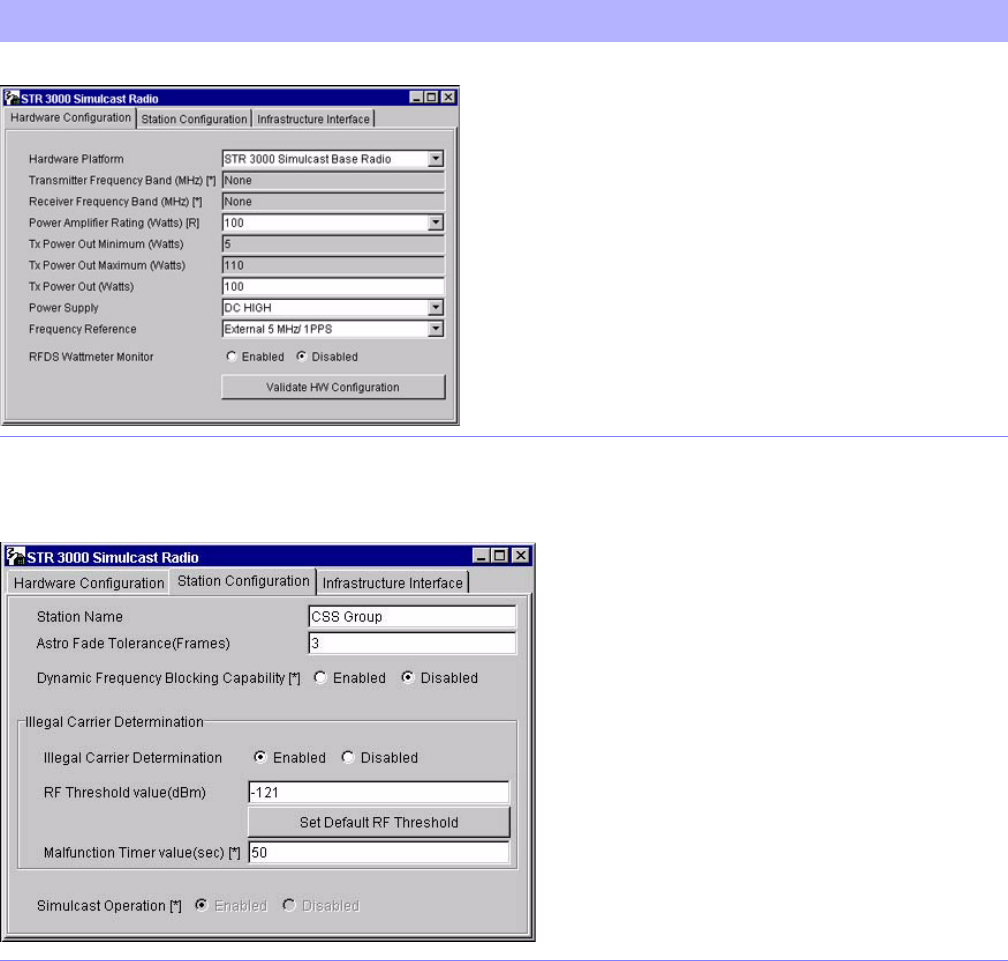
FIGURE 3-7 BASE RADIO HARDWARE CONFIGURATION SCREEN
Station Configuration Screen Provides for the simulcast base radio’s specific station configuration. See
the online documentation provided with the CSS for specific procedures.
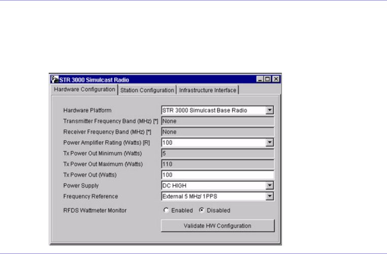
FIGURE 3-8 BASE RADIO STATION CONFIGURATION SCREEN
TABLE 3-1 SIMULCAST BASE RADIO CONFIGURATION SCREENS IN CSS (CONTINUED)
Screen Description
Exhibit 9B
68P8100XYXX-O APRIL 2003 3-9
PRELIMINARY
Internal Review (First Draft - 50% to 60% Complete)
SIMULCAST CONFIGURATION ILLEGAL CARRIER DETERMINATION AND BASE RADIO MEASUREMENT
MEASURING CHANNEL INTERFERENCE
The STR 3000 Simulcast Base Radios log interfering carrier levels that surpass the RF threshold
value to the station error log. These logs can be used to determine periodic interfering carriers
that are not present long enough to trigger the Carrier Malfunction Timer.
These logs should also be checked after any changes are made to the site that affect the site noise
floor. An example of this type of change would be seen when a new customer in the immediate
area is using the same frequency band.
SETTING THE STR 3000 SIMULCAST BASE RADIO RF
THRESHOLD VALUE FIELD
The RF Threshold Value field appears on the Station Configuration tab of the STR 3000
Simulcast Base Radio window.
This field defines the level (in dBm) above which the received signal is considered to be an
illegal carrier, if this STR 3000 Simulcast Base Radio is not assigned to a call.
Procedure 3-1 describes the steps to set the RF Threshold Value field.
PROCEDURE 3-1 HOW TO SET THE STR 3000 SIMULCAST BASE RADIO RF THRESHOLD
VALUE FIELD
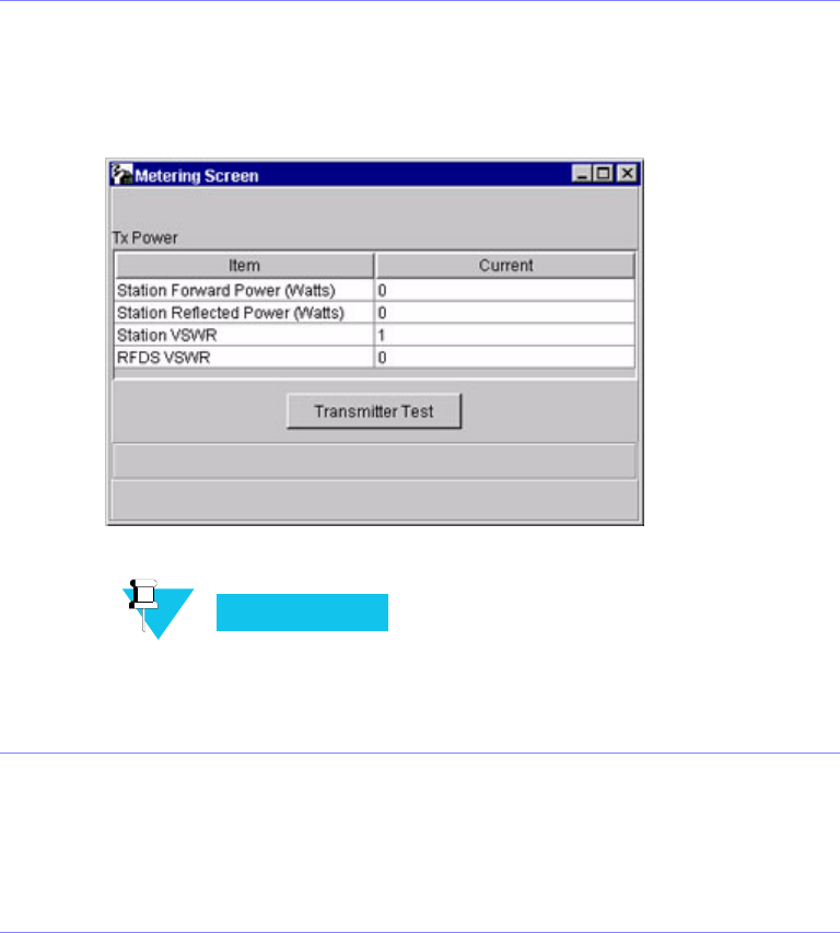
1In the CSS application, select STR 3000 Simulcast Base Radio.
Result: The STR 3000 Simulcast Base Radio window appears (Figure 3-10).
FIGURE 3-10 STR 3000 SIMULCAST BASE RADIO WINDOW SCREEN
Exhibit 9C
3-20 68P8100XYXX-O APRIL 2003
PRELIMINARY
Internal Review (First Draft - 50% to 60% Complete)
ILLEGAL CARRIER DETERMINATION AND BASE RADIO MEASUREMENT CHAPTER 3: SIMULCAST REMOTE SITE CONFIGURATION
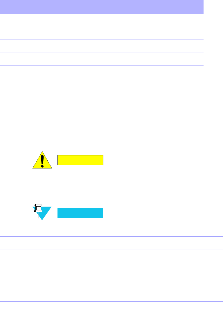
MONITORING THE TRANSMITTER METERING POINTS
Perform Procedure 3-4 to monitor the transmitter metering points.
PROCEDURE 3-4 HOW TO MONITOR THE TRANSMITTER METERING POINTS
1From the Service menu, select Metering Screen.
Results: The Metering Screen dialog box appears (Figure 3-17).
FIGURE 3-17 METERING SCREEN DIALOG BOX
NOTE
To obtain a reading for the RFDS VSWR metering point, you must be
connected inside the STR 3000 Simulcast Base Radio rack at the
bottom position, which accepts the output from the FRDS output
power meter. Otherwise, the value will be either 0 or N/A.
2Click Transmitter Test, which briefly keys up the transmitter.
Result: The status bar on the window confirms if the transmitter is operating
properly or if it has failed.
See Table 3-4 “Source for the Transmitter Metering Points” on page 3-21 for a list
of the source for each transmitter metering point.
Exhibit 9D
68P8100XYXX-O APRIL 2003 3-21
PRELIMINARY
Internal Review (First Draft - 50% to 60% Complete)
SIMULCAST CONFIGURATION ILLEGAL CARRIER DETERMINATION AND BASE RADIO MEASUREMENT
SOURCE OF THE TRANSMITTER METERING POINTS
Table 3-4 lists each of the transmitter metering points and where the measurement is taken.
CHECKING THE TRANSMITTER FREQUENCY
Perform Procedure 3-5 to measure the transmitter frequency of a base radio.
TABLE 3-4 SOURCE FOR THE TRANSMITTER METERING POINTS
Current Column Read From
Station Forward Power (Watts) Individual base radio
Station Reflected Power (Watts) Individual base radio
Station VSWR Individual base radio
RFDS VSWR Power monitor in the RFDS
PROCEDURE 3-5 HOW TO CHECK THE TRANSMITTER FREQUENCY
1Turn off the STR 3000 Simulcast Base Radio using the On and Off switch on the
front of the power supply module.
CAUTION
Make sure power to the base radio is OFF. Connecting or
disconnecting RF cables while the transmitter is keyed
could cause personal injury or equipment damage from RF
arcing.
NOTE
If two STR 3000 Simulcast Base Radio rack transmitters are
combined together, turn off all of the base radios in both racks.
2Disconnect the transmit cable from the base radio.
3Connect the transmit port to the service monitor.
4Set the service monitor to monitor the transmit frequency of the base radio being
tested.
5Turn on the base radio being checked using the On and Off switch on the front of
the power supply module and allow the station to fully initialize.
6Use the CSS application to read the configuration from the base radio.
See “Reading the Configuration File from a Device” in the STR 3000 Simulcast
Base Radio online help.
Exhibit 9E
3-22 68P8100XYXX-O APRIL 2003
PRELIMINARY
Internal Review (First Draft - 50% to 60% Complete)
ILLEGAL CARRIER DETERMINATION AND BASE RADIO MEASUREMENT CHAPTER 3: SIMULCAST REMOTE SITE CONFIGURATION
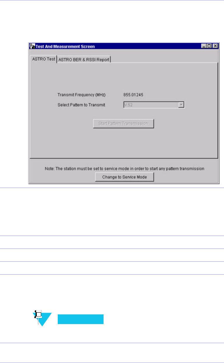
7From the Service menu, select Test and Measurement Screen.
Result: The Test and Measurement Screen dialog box appears (Figure 3-18).
FIGURE 3-18 TEST AND MEASUREMENT SCREEN DIALOG BOX
8If the station is not already in Service Mode, click Change to Service Mode.
Result: The STR 3000 Simulcast Base Radio begins a reset sequence to change
modes, which takes a few seconds.
After resetting, read the configuration data again from the base radio and then
open the Test and Measurement Screen dialog box, as described in step 7.
9Select the Standard Test pattern.
10 Click Start Pattern Transmission to start transmitting the test pattern.
11 Record the transmitted frequency.
12 Calculate the parts per million (ppm) error using the following equation:
ppm error = (Recorded frequency/assigned frequency - 1)X106
The specification is 0.15 ppm.
NOTE
If all transmitter tests are complete proceed with next step, otherwise,
go to the next transmitter test.
13 Turn off the STR 3000 Simulcast Base Radio using the On and Off switch on the
front of the power supply module.
PROCEDURE 3-5 HOW TO CHECK THE TRANSMITTER FREQUENCY (CONTINUED)
Exhibit 9E
68P8100XYXX-O APRIL 2003 3-23
PRELIMINARY
Internal Review (First Draft - 50% to 60% Complete)
SIMULCAST CONFIGURATION ILLEGAL CARRIER DETERMINATION AND BASE RADIO MEASUREMENT
CHECKING THE TRANSMITTER BIT ERROR RATE
Perform Procedure 3-6 to check the bit error rate (BER) on the transmitter.
NOTE
If the service monitor is already connected, go to step 6.
14 Disconnect the service monitor from the base radio and reconnect the transmit
antenna to the transmit input connector.
15 Turn on the base radio being checked using the On and Off switch on the front of
the power supply module and allow the station to fully initialize.
16 Click the Change to Normal Mode button to return the base radio to normal
operations.
PROCEDURE 3-6 HOW TO CHECK THE TRANSMITTER BIT ERROR RATE
1Turn off the STR 3000 Simulcast Base Radio using the On and Off switch on the
front of the power supply module.
CAUTION
Make sure power to the base radio is OFF. Connecting or
disconnecting RF cables while the transmitter is keyed
could cause personal injury or equipment damage from RF
arcing.
NOTE
If two STR 3000 Simulcast Base Radio rack transmitters are
combined together, turn off all of the base radios in both racks.
2Disconnect the transmit cable from the base radio.
3Connect the transmit port to the service monitor.
4Set the service monitor to monitor the transmit frequency of the base radio being
tested.
5Turn on the base radio being checked using the On and Off switch on the front of
the power supply module and allow the station to fully initialize.
6Use the CSS application to read the configuration from the base radio.
See “Reading the Configuration File from a Device” in the STR 3000 Simulcast
Base Radio online help.
PROCEDURE 3-5 HOW TO CHECK THE TRANSMITTER FREQUENCY (CONTINUED)
Exhibit 9E