Motorola Solutions 89FC5807 5.2GHz Fixed Wireless (UNII) User Manual BackhaulManualReg
Motorola Solutions, Inc. 5.2GHz Fixed Wireless (UNII) BackhaulManualReg
UserManual.wiki
>
Motorola Solutions
>
89FC5807 User Manual
Exhibit D Users Manual per 2 1033 b3
Navigation menu
Upload a User Manual
Namespaces
Wiki Guide
HTML
PDF
Info
Views
User Manual
Discussion / Help
Navigation


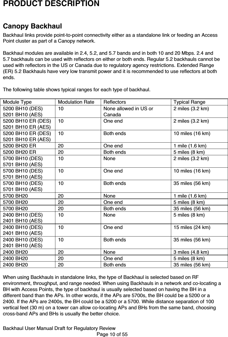
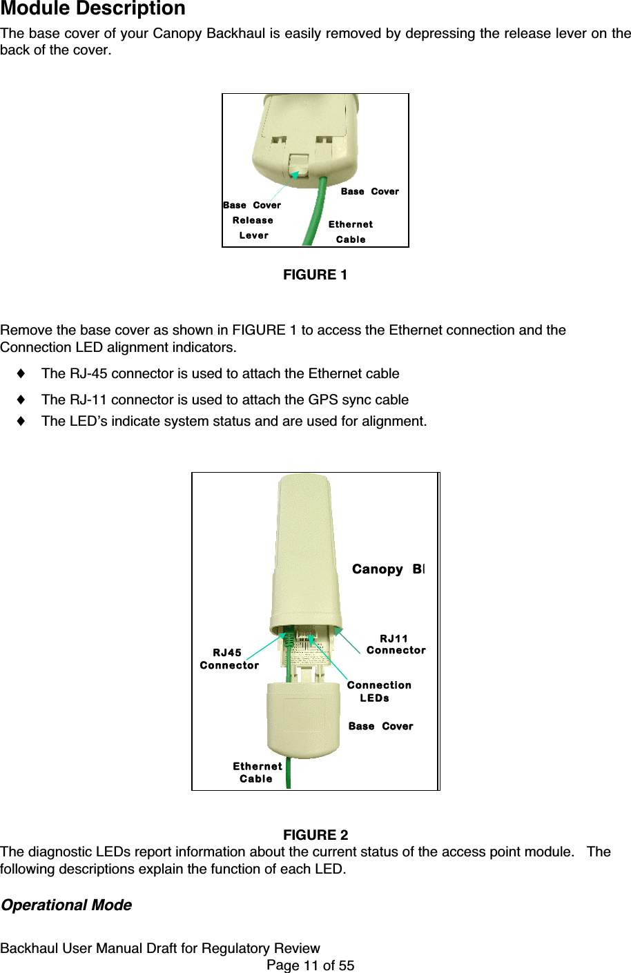
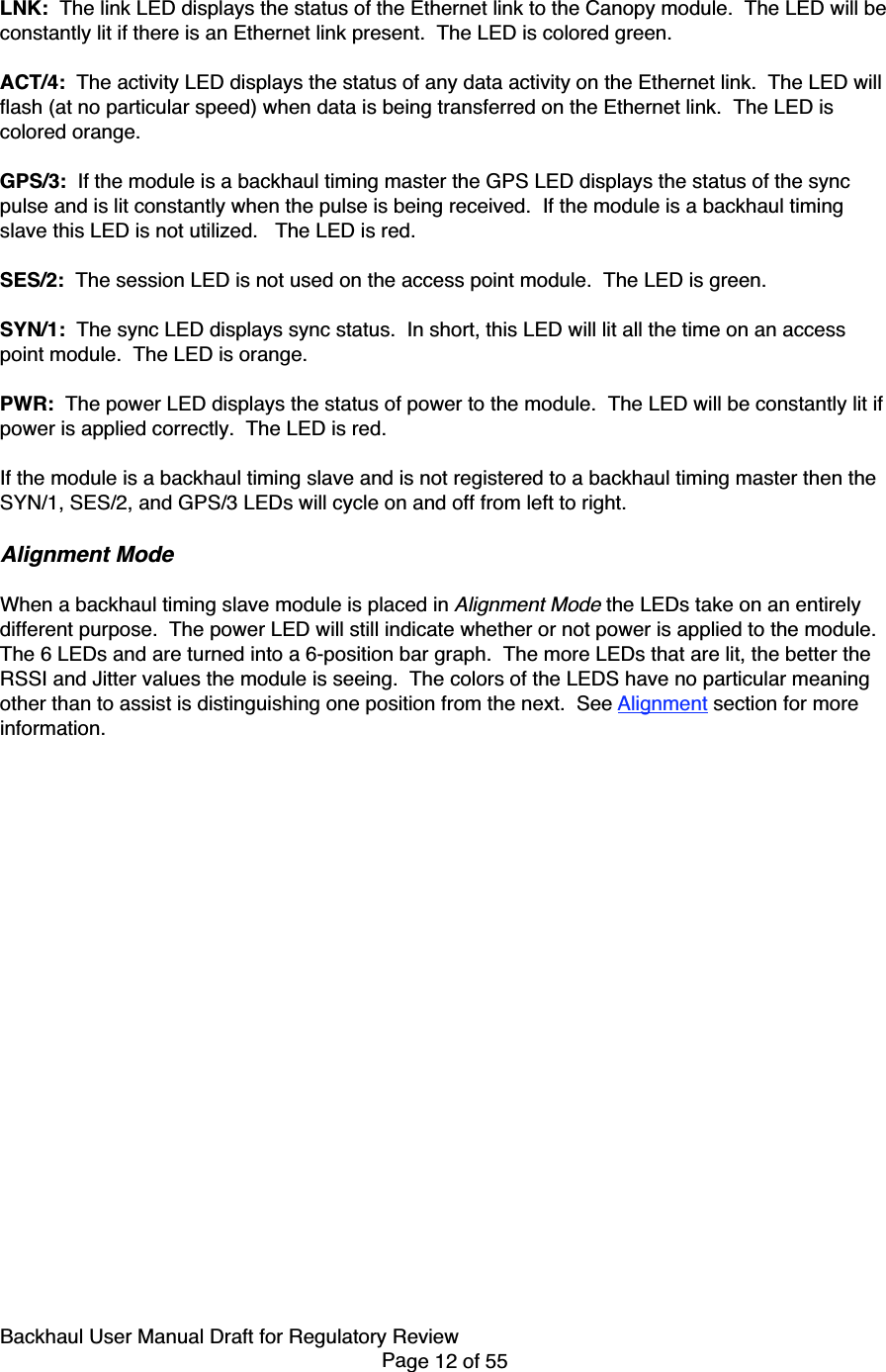
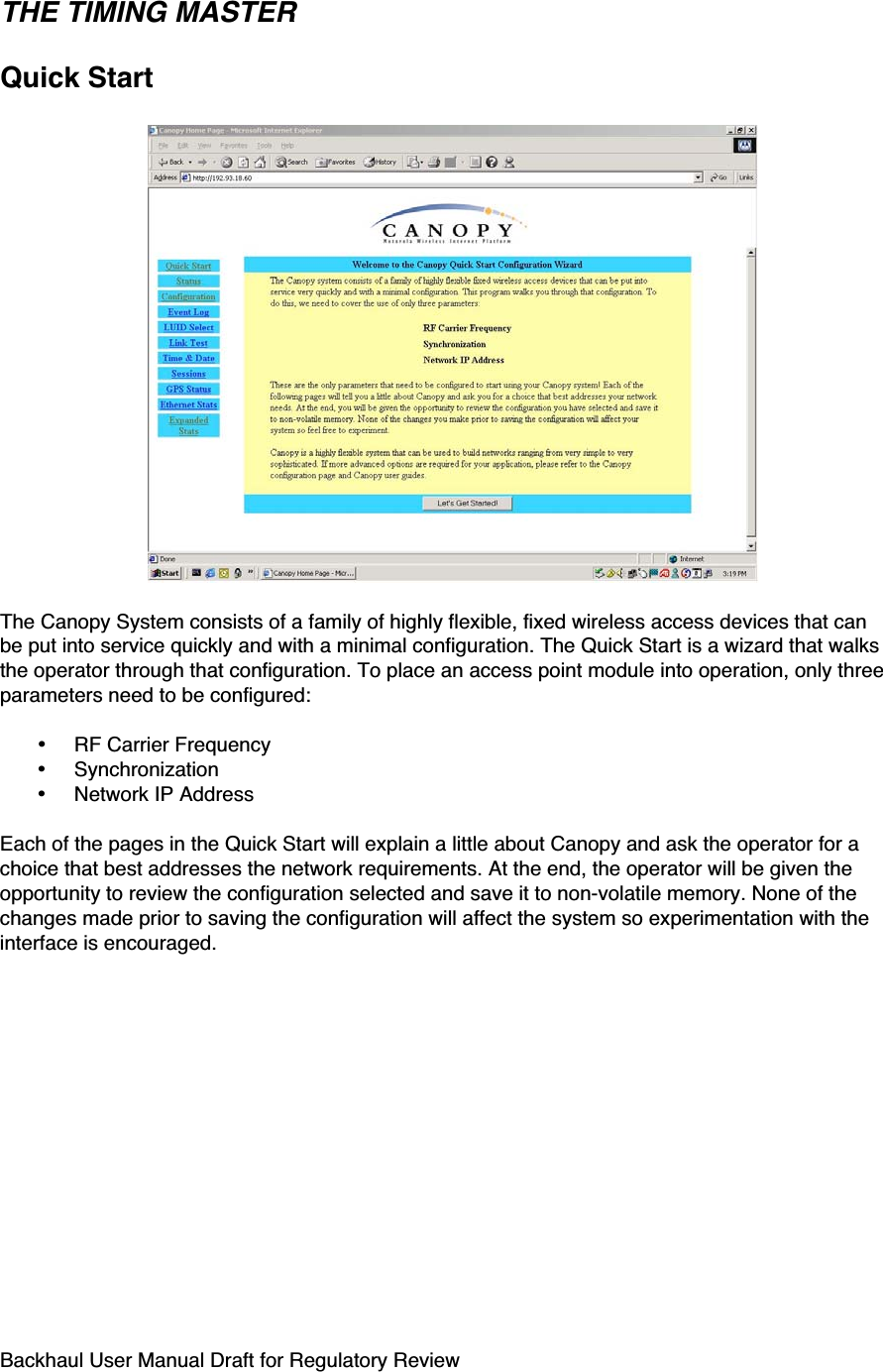
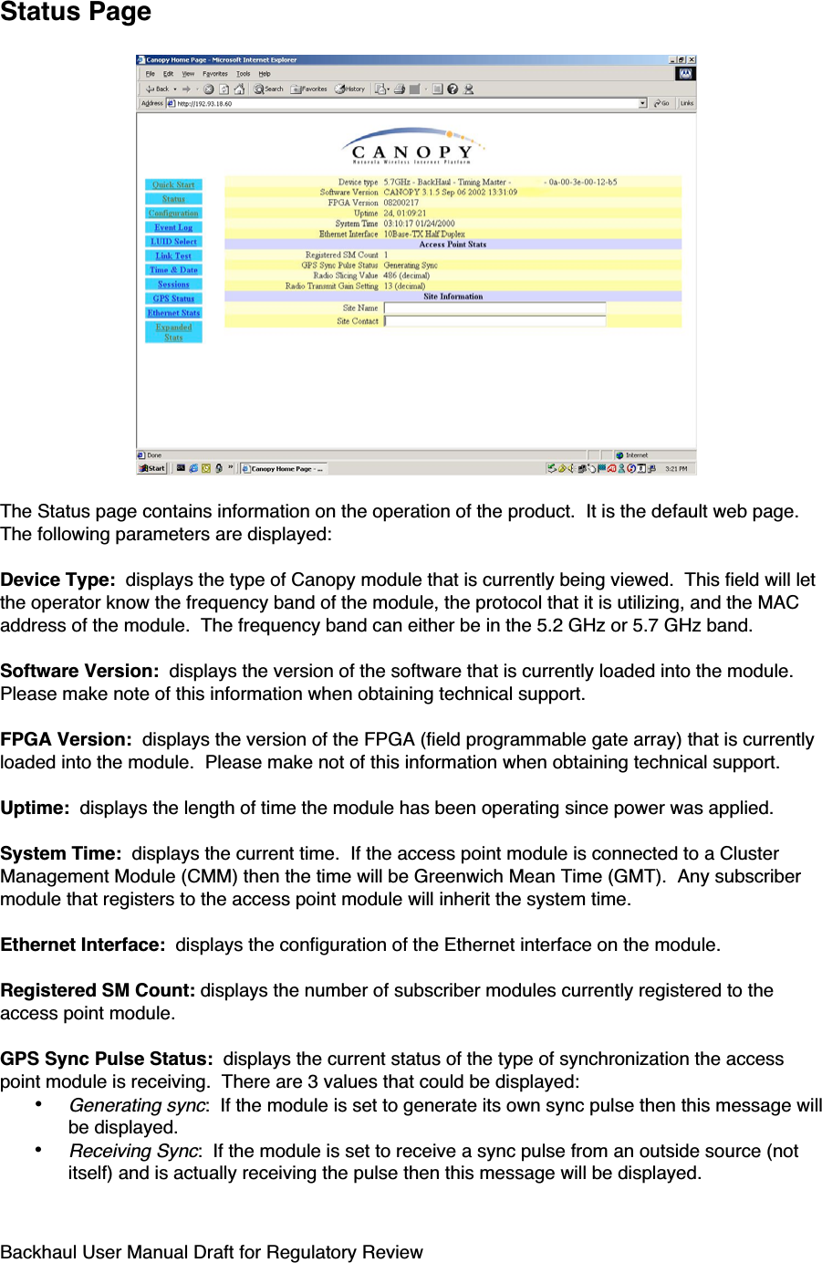
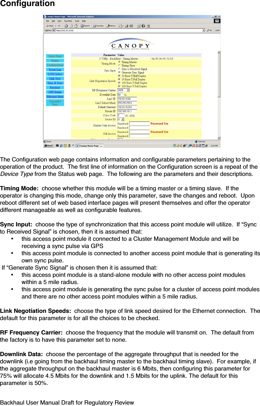
![Backhaul User Manual Draft for Regulatory ReviewPage 26 of 55module so that it can register with a backhaul timing master module. The color codes mustmatch.The operator can prevent unauthorized users from connectig to the backhaul module’s web basedinterface by assigning a password. There is no default password and password protection is turnoff is turn off from the factory.Passwords can be from 1 to 16 characters. Any combination of characters is allowed, except forthese special characters: “ , . ‘ { } / \ ; : [ ] ( ) ` ~NOTE: If the operator forgets either the password or the IP address for the module, a Canopydefault plug can be used to regain access. See Configuration for information on the default plug.There are two types of passwords that can be configured: display-only or full-access. The display-only password allows the operator to view the module’s current status. The full-access passwordallows the operator to view the module’s current status and change its configuration. By viewingthe red lettering to the right of the entry fields, the operator can discern that a password is set.The operator can enter in information about the Site Name, Location, and Contact. This is optional.See the Access Point Cluster and Cluster Management Module user manual for detailson configuration and installation of a cluster management module.Installation of the equipmentWhen power is applied to a Canopy module or the unit reset via the web-based interface, themodule will take approximately 25 seconds to boot up. During this boot up time, power on self-tests and other diagnostics are being performed.The following steps are needed to install the Canopy equipment:• Remove the base cover from all Canopy backhaul timing master modules to be installed.• Remove the GPS sync cable knockout from the base cover with needle-nose pliers.• Mount the backhaul modules:o The modules can be mounted in a variety of locations, choose the best locationfor your particular application. Mounting can be done by utilizing stainless steelhose clamps or another equivalent fastener.• Route the Ethernet cable from the backhaul module to the cluster management module.o The Ethernet cables use RJ-45 connectors (standard Ethernet) that connect tomatching ports within the cluster management module.o A total of 8 ports are available on the cluster management module, toaccommodate a combination of access point modules and backhaul timing mastermodules.• Route the GPS sync (serial) cable from the backhaul timing master module to the clustermanagement module.o The GPS sync cables use 6 conductor RJ-11 connectors that connect to matchingports within the cluster management module.](https://usermanual.wiki/Motorola-Solutions/89FC5807/User-Guide-383388-Page-26.png)