Motorola Solutions 89FC5808 2.4GHz Fixed Wireless (ISM) User Manual APCMM2ManualIss4Draft
Motorola Solutions, Inc. 2.4GHz Fixed Wireless (ISM) APCMM2ManualIss4Draft
UserManual.wiki
>
Motorola Solutions
>
89FC5808 User Manual
Exhibit D Users Manual per 2 1033 b3
Navigation menu
Upload a User Manual
Namespaces
Wiki Guide
HTML
PDF
Info
Views
User Manual
Discussion / Help
Navigation


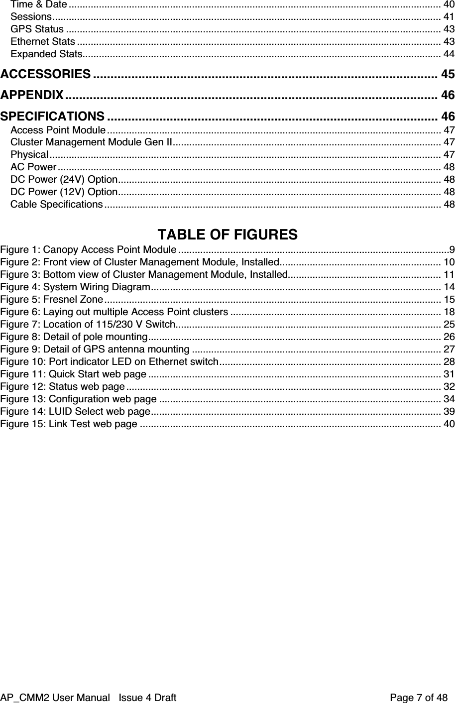
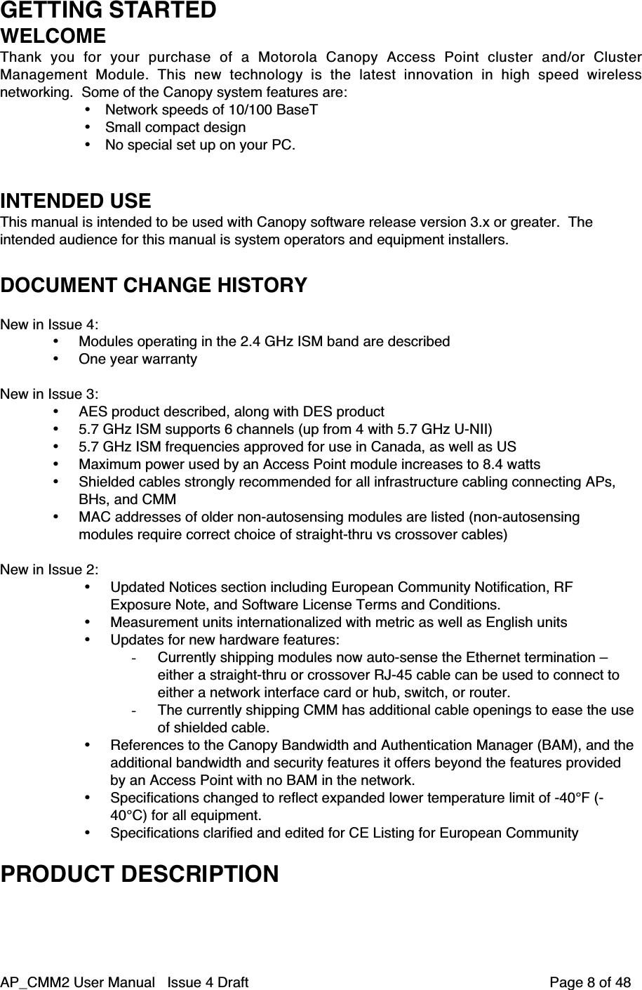
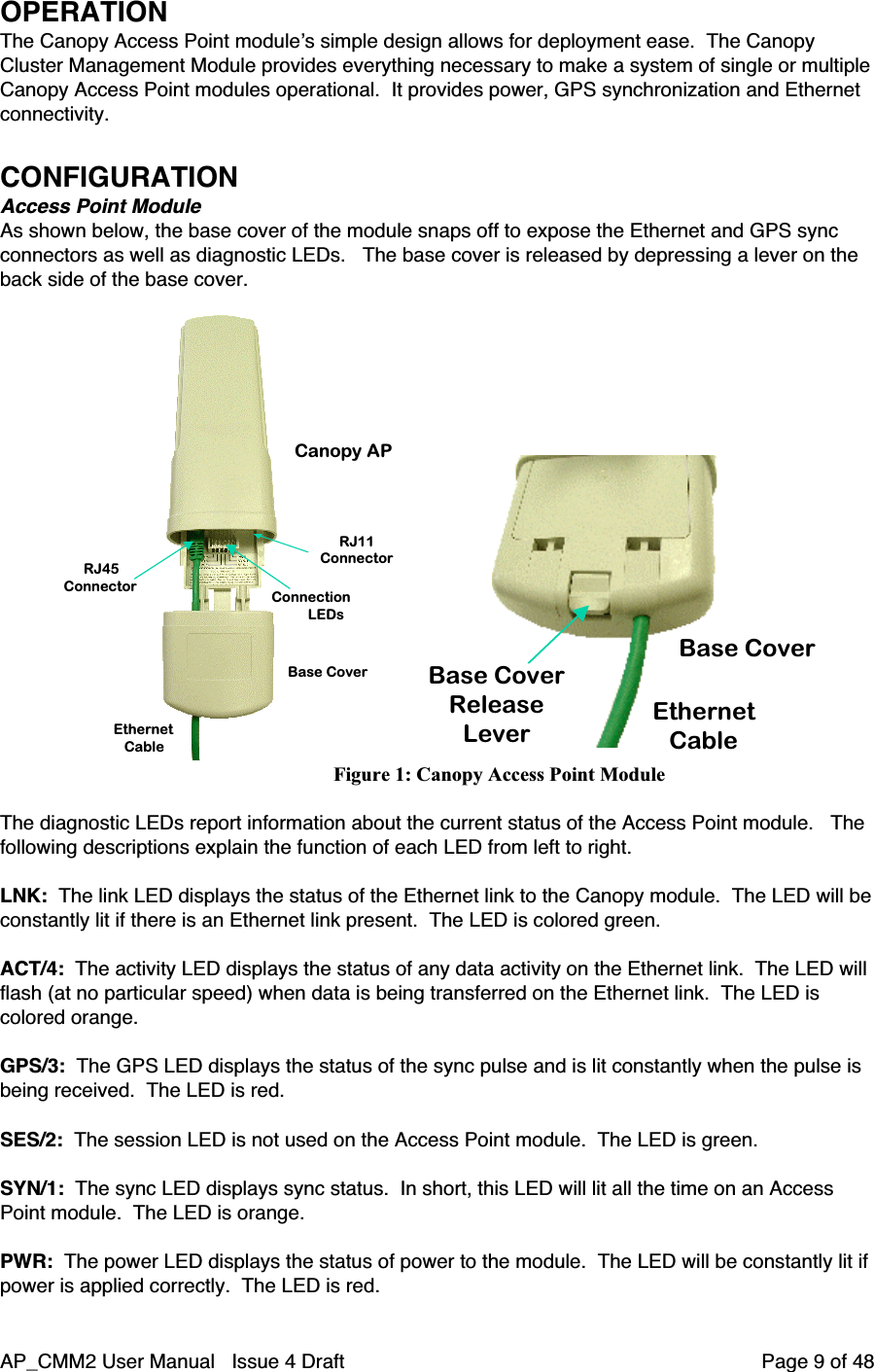
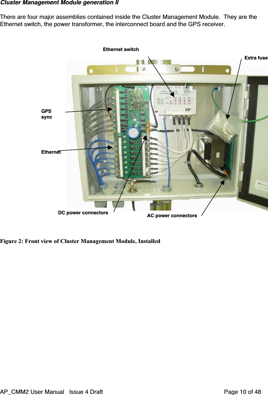

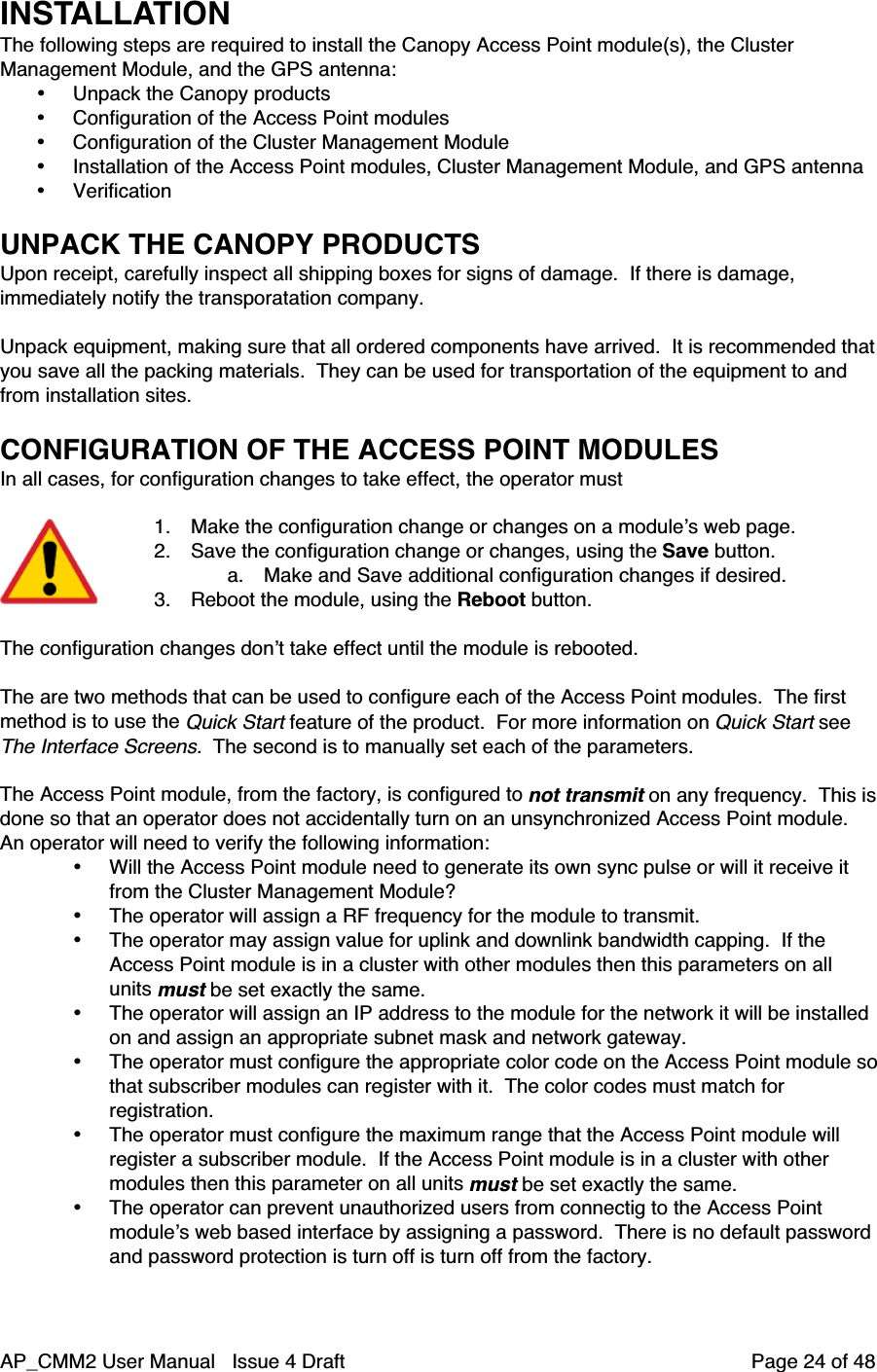
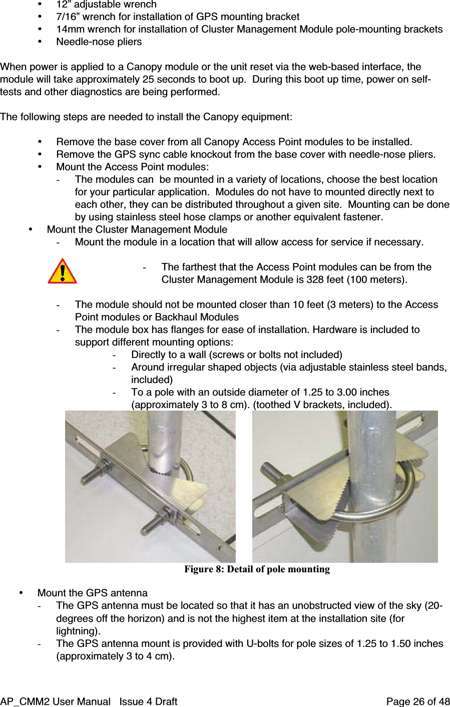
![AP_CMM2 User Manual Issue 4 Draft Page 25 of 48- Passwords can be from 1 to 16 characters. Any combination of charactersis allowed, except for these special characters: “ , . ‘ { } / \ ; : [ ] ( ) ` ~- NOTE: If the operator forgets either the password or the IP address forthe module, a Canopy default plug can be used to regain access. Fordetails, see the section on the default plug under Interface Screens.- There are two types of passwords that can be configured: display-only orfull-access. The display-only password allows the operator to view themodule’s current status. The full-access password allows the operator toview the module’s current status and change its configuration. By viewingthe red lettering to the right of the entry fields, the operator can tell that apassword is set, but can’t see the password.• The operator can enter information about the Site Name, Location, and Contact. Thisis optional.CONFIGURATION OF THE CLUSTER MANAGEMENT MODULEThe operator will need to verify the following when configuring a Cluster Management Module:• What type of power will the module use, AC or DC?• If using AC power, there is a switch to choose 115V or 230V on thepower transformer. This switch must be set correctly before power isapplied, or the unit may be damaged. See the schematic inside theCluster Management Module for further information.115/230 V switchAC powerconnectorsFuse receptacleFigure 7: Location of 115/230 V Switch• The AC power connectors are labeled- N for Neutral- L for Line- PE for Protective Earth (PE) (ground)• The maximum thickness wire to be used is 12 AWG (4 mm2).INSTALLATION OF THE EQUIPMENTThe following tools may be needed during installation:• 3/8” nut driver](https://usermanual.wiki/Motorola-Solutions/89FC5808/User-Guide-376110-Page-25.png)