Motorola Solutions 89FC5823B Non Broadcast Transmitter User Manual Summit BR 800 Tx FCC Filing 3
Motorola Solutions, Inc. Non Broadcast Transmitter Summit BR 800 Tx FCC Filing 3
Exhibit D Users Manual per 2 1033 c3

APPLICANT: MOTOROLA SOLUTIONS EQUIPMENT TYPE: ABZ89FC5823B
109AB-5823B
EXHIBIT D
User / Operational Manual
Operational or User’s Manual
The manual should include instruction, installation, operator, or technical manuals with required ‘information to the
users’. This manual should include a statement that cautions the user that changes or modifications not expressly
approved by the party responsible for compliance could void the user’s authority to operate the equipment. The
manual shall include RF Hazard warning statements, if applicable.
Draft copy of some of the manual information has been assembled and has been included as part of this filing
package.
Upon request, published and/or printed manuals will be sent to the commission and/or telecommunication
certification body (TCB). All of the descriptions, block diagrams, and schematics that are included in this filing
package are current as of the package submittal date.
EXHIBIT DESCRIPTION
D1-1 Manual Front Matter (Draft)
D1-2 Specifications (Draft)
D1-3 Field Replaceable Units and Orderable Parts (Draft)
D1-4 Tune-Up Procedure
D1-5 Racking Configurations
D1-6 Functional Description / Operation of Modules (Draft)
APPLICANT: MOTOROLA SOLUTIONS EQUIPMENT TYPE: ABZ89FC5823B
109AB-5823B
EXHIBIT D1-1
User / Operational Manual
Manual Front Matter
A copy of the multi-lingual lingual document, “General Safety Precautions and Installation Standards and Guidelines”, is
included with each base radio shipped. This document gives general safety precautions pertaining to installation and RF
exposure. The English and French sections are included, below, as part of this filing package.
English: General Safety Precautions and Installation Standards and Guidelines
WARNING: For safe installation, operation, service and repair of this equipment, follow the safety precautions and instructions
described below, as well as any additional safety information in Motorola’s product service and installation manuals and the Motorola
R56 Standards and Guidelines for Communications Sites manual (6881089E50). To obtain copies of these materials, please contact
Motorola as directed at the end of this document. After installation, these instructions should be retained and readily available for any
person operating or servicing this base station or working near it.
Failure to follow these safety precautions and instructions could result in serious injury or property damage.
The installation process requires preparation and knowledge of the site before installation begins. Review installation procedures and
precautions in the Motorola R56 manual before performing any site or component installation. Personnel must use safe work practices
and good judgment, and always follow applicable safety procedures, such as requirements of the Occupational Safety and Health
Administration (OSHA), the National Electrical Code (NEC), and local codes.
The following are additional general safety precautions that must be observed:
• To continue compliance with any applicable regulations and maintain the safety of this equipment, do not install substitute parts
or perform any unauthorized modifications.
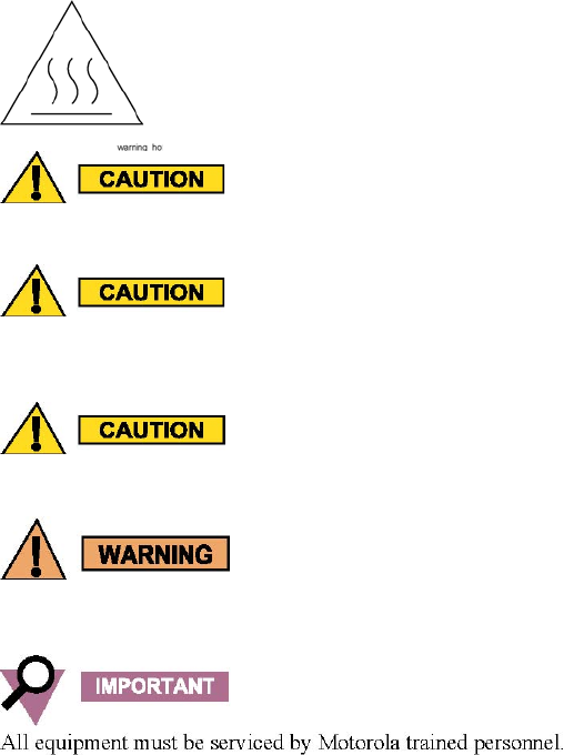
• All equipment must be serviced by Motorola trained personnel.
• If troubleshooting the equipment while the power is on, be aware of the live circuits which could contain hazardous voltage.
• Do not operate the radio transmitters unless all RF connectors are secure and all connectors are properly terminated.
• All equipment must be properly grounded in accordance with the Motorola R56 and specified installation instructions for safe
operation.
• Slots and openings in the cabinet are provided for ventilation. Do not block or cover openings that protect the devices from
overheating.
• Some equipment components can become extremely hot during operation. Turn off all power to the equipment and wait until
sufficiently cool before touching.
• Maintain emergency first aid kits at the site.
• Never store combustible materials in or near equipment racks. The combination of combustible material, heat and electrical
energy increases the risk of a fire hazard.
• Equipment shall be installed in site that meets the requirements of a “restricted access location”, per (UL60950-1 & EN60950-1),
which is defined as follows: “Access can only be gained by service persons or by users who have been instructed about the
reasons for the restrictions applied to the location and about any precautions that shall be taken; and access is through the use of a
tool or lock and key, or other means of security, and is controlled by the authority responsible for the location.”
• Burn hazard. The metal housing of the product may become extremely hot. Use caution when working around the equipment.
• RF energy burn hazard. Disconnect power in the cabinet to prevent injury while disconnecting and connecting antennas.
• Shock hazard. The outer shields of all TX and RX cables must be grounded per Motorola R56 manual.
• Shock hazard. DC input voltage shall be no higher than 60VDC. This maximum voltage shall include consideration of the battery
charging “float voltage” associated with the intended supply system, regardless of the marked power rating of the equipment.
• All TX and RX RF cables shall be connected to a surge protection device according to Motorola R56 manual. Do not connect TX
and RX RF cables directly to an outside antenna.
• Compliance with National and International standards and guidelines for human exposure to Electromagnetic Energy (EME) at
Transmitter Antenna sites generally requires that persons having access to a site shall be aware of the potential for exposure to
EME and can exercise control of exposure by appropriate means, such as adhering to warning sign instructions. See this
installation manual and Appendix A of Motorola R56.
Refer to product specific manuals for detailed safety and installation instructions. Manuals can be obtained with product orders,
downloaded from https://businessonline.motorola.com, or purchased through the Motorola Aftermarket & Accessory Department.
APPLICANT: MOTOROLA SOLUTIONS EQUIPMENT TYPE: ABZ89FC5823B
109AB-5823B
EXHIBIT D1-1
User / Operational Manual
Manual Front Matter
Français Canadien: Consignes générales de sécurité et d’installation
AVERTISSEMENT : pour une installation, un fonctionnement, un entretien et des reparations de cet équipement sans risque,
respectez les mesures de sécurité et instructions décrites ci-dessous ainsi que les consignes de sécurité supplémentaires présentées dans
les guides d’entretien et d’installation des produits Motorola et dans le manuel de Motorola intitulé Standards and Guidelines for
Communications Sites, R56 (6881089E50). Pour obtenir des copies de ces documents, adressez-vous à Motorola selon la procédure
indiquée à la fin de ce document. Après l’installation, conservez ces instructions pour que toute personne utilisant ou réparant cette
station de base ou travaillant à proximité puisse s’y référer facilement.
Ne pas suivre ces mesures de sécurité et ces instructions peut entraîner des blessures graves ou des dommages matériels.
Le processus d’installation exige une préparation et une connaissance préalable du site. Passez en revue les procédures d’installation et
les consignes de sécurité en consultant le manuel Motorola R56 avant de procéder à toute installation sur le site ou à toute installation
d’un composant. Le personnel doit adopter des pratiques professionnelles sécuritaires et faire preuve de bon sens et toujours respecter
les procédures de sécurité applicables, telles que les exigences des norms Occupational Safety and Health Administration (OSHA),
celles du Code national de l’électricité ou de tout autre code en vigueur dans votre région.
Les consignes de sécurité générales supplémentaires suivantes doivent également être respectées:
• Pour continuer à respecter toute réglementation applicable et assurer la sécurité de cet équipement, n’installez aucune pièce de
rechange et ne modifiez aucune pièce de l’équipement sans autorisation.
• Tout équipement doit être entretenu par le personnel formé de Motorola.
• Si vous tentez une procédure de dépannage de l’équipement alors qu’il est sous tension, portez attention aux circuits alimentés qui
pourraient présenter un danger électrique.
• N’utilisez pas d’émetteurs-récepteurs radio à moins que tous les connecteurs RF soient solidement branchés et que tous les
connecteurs soient adéquatement protégés d’un embout.
• Tout équipement doit comporter un dispositif de mise à la terre adéquat, conformément au manuel Motorola R56 et aux
instructions détaillées d’installation assurant une utilisation sans risque.
• Les fentes et les ouvertures du caisson servent à l’aération. Évitez d’obstruer ou de recouvrir ces ouvertures qui empêchent les
appareils de surchauffer.
• Certains composants peuvent devenir très chauds durant l’utilisation. Mettez l’équipement hors tension et attendez qu’il
refroidisse suffisamment avant de le toucher.
• Veillez à ce que le site dispose d’une trousse d’urgence et de premiers soins en tout temps.
• Ne rangez jamais des matières combustibles sur ou près des étagères destinées à l’équipement. La combinaison matières
combustibles- chaleur-énergie électrique augmente le risque d’incendie.
• Tout équipement doit être installé sur les sites conformément aux exigences relatives aux « emplacements à accès restreint » (voir
UL60950-1 et EN60950-1) qui se définissent comme suit : « L’accès est uniquement donné au personnel d’entretien ou à toute
autre personne informée des raisons justifiant les restrictions touchant l’accès au lieu et de toutes les précautions à prendre;
l’accès est restreint à l’aide d’outils, de cadenas, d’une clé ou de tout autre dispositif de sécurité et est contrôlé par l’autorité
responsable du site. »
• Risques de brûlure. Le boîtier métallique du produit peut devenir extrêmement chaud. Faites attention lorsque vous travaillez près
de l’équipement.
• Risques de brûlure causée par l’énergie de radiofréquence. Coupez le courant du caisson pour éviter les blessures lors du
débranchement et du branchement des antennes.
• Risques de décharge électrique. Le blindage de tous les câbles d’émission et de réception doit comporter un dispositif de mise à la
terre conforme aux exigences décrites dans le manuel Motorola R56.
• Risques de décharge électrique. La tension d’entrée de courant continu ne doit pas dépasser 60 V c.c. Cette tension maximale doit
tenir compte de la « tension d’annonciation » du chargement de la batterie associée au système d’alimentation voulu, peu importe
le type de puissance de l’équipement indiqué.
• Le blindage de tous les câbles RF d’émission et de réception doit comporter un dispositif de protection contre les surtensions
conformément au manuel Motorola R56. Ne branchez pas les câbles RF d’émission et de réception directement sur l’antenne
extérieure.
• Les normes et directives nationales et internationales en matière d’exposition à l’énergie électromagnétique à proximité des
antennes émettrices exigent, en général, que les personnes ayant accès à de tels sites soient conscientes du risque d’être exposées à
l’énergie électromagnétique et de la possibilité de contrôler ces risques d’exposition en respectant strictement les instructions
figurant sur les panneaux d’avertissement. Référez-vous à ce manuel d’installation et à l’annexe A du manuel Motorola R56.
Consultez les manuels spécifiques au produit pour des instructions détaillant les mesures de sécurité et la procédure d’installation. Ces
manuels peuvent accompagner le produit commandé, être téléchargés du site https://businessonline.motorola.com ou être achetés
auprès du service Accessoires et pieces de rechange de Motorola.

APPLICANT: MOTOROLA SOLUTIONS EQUIPMENT TYPE: ABZ89FC5823B
109AB-5823B
EXHIBIT D1-1
User / Operational Manual
Manual Front Matter (Draft)
Copyrights
The Motorola products described in this document may include copyrighted Motorola computer programs. Laws in the
United States and other countries preserve for Motorola certain exclusive rights for copyrighted computer programs.
Accordingly, any copyrighted Motorola computer programs contained in the Motorola products described in this
document may not be copied or reproduced in any manner without the express written permission of Motorola.
© 2013 Motorola Solutions, Inc. All Rights Reserved
No part of this document may be reproduced, transmitted, stored in a retrieval system, or translated into any language or
computer language, in any form or by any means, without the prior written permission of Motorola Solutions, Inc.
Furthermore, the purchase of Motorola products shall not be deemed to grant either directly or by implication, estoppel or
otherwise, any license under the copyrights, patents or patent applications of Motorola, except for the normal
nonexclusive, royalty-free license to use that arises by operation of law in the sale of a product.
Disclaimer
Please note that certain features, facilities, and capabilities described in this document may not be applicable to or
licensed for use on a particular system, or may be dependent upon the characteristics of a particular mobile subscriber
unit or configuration of certain parameters. Please refer to your Motorola contact for further information.
Trademarks
MOTOROLA, MOTO, MOTOROLA SOLUTIONS, and the Stylized M Logo are trademarks or registered trademarks of
Motorola Trademark Holdings, LLC and are used under license. All other trademarks are the property of their respective
owners.
European Union (EU) Waste of Electrical and Electronic Equipment (WEEE)
directive
The European Union's WEEE directive requires that products sold into EU countries must have the crossed out trash
bin label on the product (or the package in some cases).
As defined by the WEEE directive, this cross-out trashbin label means that customers and end-users in EU countries
should not dispose of electronic and electrical equipment or accessories in household waste.
Customers or end-users in EU countries should contact their local equipment supplier representative or service centre for
information about the waste collection system in their country.
FCC Requirements
Radio frequency (RF) transmitters installed at sites within the US must be in compliance with the following FCC
regulations:
• The station licensee shall be responsible for the proper operation of the station at all times and is expected to
provide observations, servicing, and maintenance as often as may be necessary to ensure proper operation.
• The transmitter ERP shall not exceed the maximum power specified on the current station authorization.
• The frequency of the transmitter must be checked during initial installation of the transmitter, when replacing
modules, or when making adjustments that affect the carrier frequency or modulation characteristics.
This equipment has been tested and found to comply with the limits for a Class A digital device, according to part 15
of the FCC Rules. These limits are designed to provide reasonable protection against harmful interference to radio
communications when the equipment is operated in a commercial environment.
This equipment generates, uses, and can radiate radio frequency energy. If not installed properly and used in
accordance with the instruction manuals, the equipment may cause harmful interference to radio communications.
Operation of some compliant equipment in a residential area may cause harmful interference to radio
communications, in which case the user is required to correct the interference.
APPLICANT: MOTOROLA SOLUTIONS EQUIPMENT TYPE: ABZ89FC5823B
109AB-5823B
EXHIBIT D1-1
User / Operational Manual
Manual Front Matter (Draft, Continued)
About GTR 8000 Base Radio - What Is Covered In This Manual?
This manual contains the following chapters:
• Chapter 1 GTR 8000 Base Radio Description provides a high-level description of the GTR 8000 Base Radio and
the function it serves on your system.
• Chapter 2 GTR 8000 Base Radio Theory of Operation explains how the GTR 8000 Base Radio works in the
context of your system.
• Chapter 3 GTR 8000 Base Radio Installation details installation procedures relating to the GTR 8000 Base
Radio.
• Chapter 4 GTR 8000 Base Radio Configuration details configuration procedures relating to the GTR 8000 Base
Radio.
• Chapter 5 GTR 8000 Base Radio Optimization contains optimization procedures and recommended settings
relating to the GTR 8000 Base Radio.
• Chapter 6 GTR 8000 Base Radio Maintenance describes periodic maintenance procedures relating to the GTR
8000 Base Radio.
• Chapter 7 GTR 8000 Base Radio Operation details tasks that you will perform once the GTR 8000 Base Radio
is installed and operational on your system.
• Chapter 8 GTR 8000 Base Radio Troubleshooting provides fault management and troubleshooting information
relating to the GTR 8000 Base Radio.
• Chapter 9 GTR 8000 Base Radio FRU Procedures lists the Field Replaceable Units (FRUs) and Field
Replaceable Entities (FREs) and includes replacement procedures applicable to the GTR 8000 Base Radio.
• Chapter 10 GTR 8000 Base Radio Reference contains supplemental reference information relating to the GTR
8000 Base Radio indicator LEDs.
• Chapter 11 GTR 8000 Base Radio Disaster Recovery provides references and information that enables you to
recover a GTR 8000 Base Radio in the event of failure.
Useful Background Information
Motorola offers various courses designed to assist in learning about the system. For information, go to
http://www.motorolasolutions.com/training to view the current course offerings and technology paths.
Related Information
In addition to the information in the table below, see the Related Information Guide.

APPLICANT: MOTOROLA SOLUTIONS EQUIPMENT TYPE: ABZ89FC5823B
109AB-5823B
EXHIBIT D1-1
User / Operational Manual
Manual Front Matter (Draft, Continued)
General Safety Precautions
Compliance with FCC guidelines for human exposure to
Electromagnetic Energy (EME) at Transmitter Antenna sites generally
requires that Personnel working at a site shall be aware of the
potential for exposure to EME and can exercise control of exposure by appropriate means, such as adhering
to warning sign instructions, using standard operating procedures (work practices), wearing personal
protective equipment, or limiting the duration of exposure. For more details and specific guidelines, see
Appendix A of the Motorola Standards and Guidelines for Communications Sites manual.
Observe the following general safety precautions during all phases of operation, service, and repair of the equipment
described in this manual. Follow the safety precautions listed and all other warnings and cautions necessary for the safe
operation of all equipment. Refer to the appropriate section of the product service manual for additional pertinent safety
information. Because of the danger of introducing additional hazards, do not install substitute parts or perform any
unauthorized modifications of equipment.
The installation process requires preparation and knowledge of
the site before installation begins. Review installation procedures
and precautions in the Motorola Standards and Guidelines for
Communications Sites manual before performing any site or component installation.
Always follow all applicable safety procedures, such as Occupational Safety and Health Administration (OSHA)
requirements, National Electrical Code (NEC) requirements, local code requirements, safe working practices. Also, good
judgment must be made by personnel. General safety precautions include the following:
Read and follow all warning notices and instructions marked on the product or included in this manual before
installing, servicing, or operating the equipment. Retain these safety instructions for future reference.
If troubleshooting the equipment while power is on, be aware of the live circuits.
Do not operate the radio transmitters unless all RF connectors are secure and all connectors are properly
terminated.
All equipment must be properly grounded in accordance with the Motorola Standards and Guidelines for
Communications Sites manual and specified installation instructions for safe operation.
Slots and openings in the cabinet are provided for ventilation. Do not block or cover openings that protect the
devices from overheating.
Only a qualified technician familiar with similar electronic equipment should service equipment.
Some equipment components can become extremely hot during operation. Turn off all power to the equipment
and wait until sufficiently cool before touching.
Maintain emergency first aid kits at the site.
Have personnel call in with their travel routes to help ensure their safety while traveling between remote sites.
Institute a communications routine during certain higher risk procedures where the on-site technician continually
updates management or safety personnel of the progress so that help can be dispatched if needed.
Never store combustible materials in or near equipment racks. The combination of combustible material, heat,
and electrical energy increases the risk of a fire safety hazard.
Equipment shall be installed in site meeting the requirements of a "restricted access location," per UL60950-1,
which is defined as follows: "Access can only be gained by service persons or by user who has been warned
about the possible burn hazard on equipment metal housing. Access to the equipment is through the use of a tool
or lock and key, or other means of security, and is controlled by the authority responsible for the location."
Burn hazard. The metal housing of the product may become extremely hot. Use caution when working around the
equipment.
APPLICANT: MOTOROLA SOLUTIONS EQUIPMENT TYPE: ABZ89FC5823B
109AB-5823B
EXHIBIT D1-1
User / Operational Manual
Manual Front Matter (Draft, Continued)
Warning Label on Hot Modules
All Tx and Rx RF cables' outer shields must be grounded per Motorola Standards and Guidelines for
Communications Sites manual requirements.
DC input voltage shall be no higher than 60VDC.This maximum voltage shall include consideration of the battery
charging "float voltage" associated with the intended supply system, regardless of the marked power rating of the
equipment. Failure to follow this guideline may result in electric shock.
All Tx and Rx RF cables shall be connected to a surge protection device according to the Motorola Standards and
Guidelines for Communications Sites manual. Do not connect Tx and Rx RF cables directly to outside antenna.
RF energy burn hazard. Disconnect power in the cabinet to prevent injury while disconnecting and connecting
antennas.
GTR 8000 Base Radio Supplemental Safety Installation Requirements
The Supplemental Safety and Installation Requirements include the following:
The GTR 8000 Base Radio must be installed in a suitable, in-building enclosure. A restricted access location is
required when installing this equipment into the end system.
The base radio contains a Class 1 built-in power supply component. This component is equipped with an
appliance inlet for connecting to an AC input, as well as DC input terminals which meet SELV DC circuit
requirements.
When installing the equipment, all requirements of relevant standards and local electrical codes must be
fulfilled.
The maximum operating ambient temperature of this equipment is 60°C. The maximum operating altitude is
3000 meters above sea level.
The 28.6 VDC output from the power supply to the PA is at an energy hazard level (exceeds 240 VA). When
installing into the end system, care must be taken so as not to touch the output wires.
When the GTR 8000 Base Radio / Repeater is used in a DC reverting system, the DC power supply must be
located in the same building as the GTR 8000 Base Radio, and it must meet the requirements of a SELV circuit.
APPLICANT: MOTOROLA SOLUTIONS EQUIPMENT TYPE: ABZ89FC5823B
109AB-5823B
EXHIBIT D1-2
User / Operational Manual
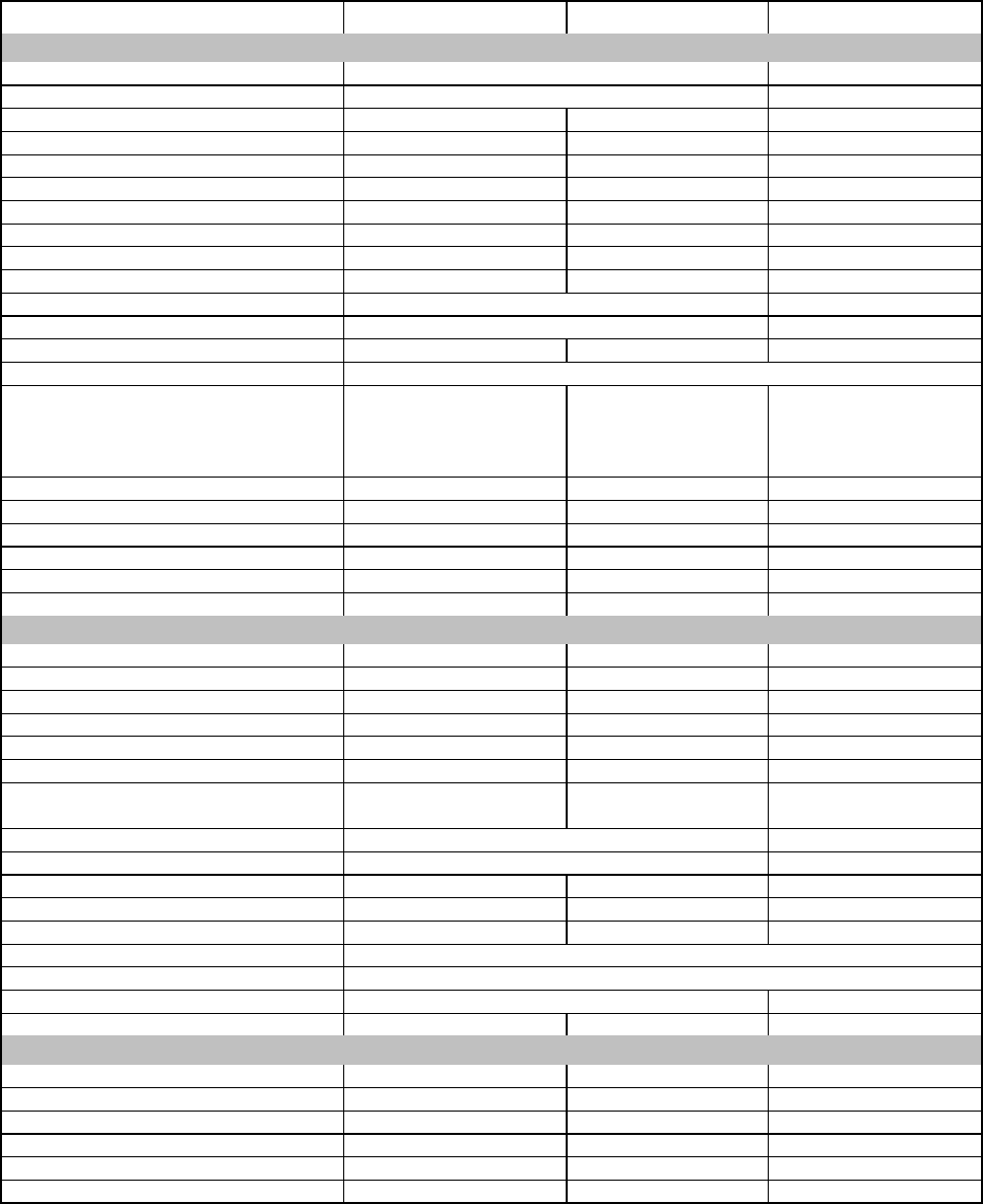
Specifications (Draft)
General Performance
Model T7039 (GTR 8000 Base Radio)
H x W x D 5.25" x 19" x 18" (133x483x457mm)
Weight 46 lbs (21 kg)
Power Requirements
AC: 90-264 VAC, 47-63 Hz
DC: 43.2-60 VDC
Temperature Range -30 to 60C (-22 to 140F)
Input / Output Impedance 50 ohms
Antenna Connectors
Transmit: N female
Receive: BNC female (without preselector)
N female (with preselector)
Frequency Stability Capable of External Reference Frequency and Time
Frequency Stability: Internal Reference
(Transceiver Option Card)
Aging:
30 ppb/yr
100ppb/5yr
Tempearture: 40 ppb
Frequency Generation Synthesized
Channel Spacing
Digital - C4FM, Linear Modulations: 12.5 kHz
Analog Frequency Modulation: 12.5 kHz, 25 kHz
Transmitter
Frequency Range 935-941 MHz
Power output
C4FM Digital and Analog: 2-120 Watts
Linear Digital Modulations: 2-120 Watts (Average)
Electronic Bandwidth Full Bandwidth
Intermodulation Attenuation 80 dB
Spurious and Harmonic Emissions
Attenuation 90 dB
Adjacent Channel Power Ratio 12.5 kHz offset, 6 kHz BW
Modulation C4FM, LSM, H-DQPSK, FM
Modulation Fidelity 5%
Analog FM Hum and Noise 45 dB (12.5 kHz)
Analog Audio Distortion Less than 2% at 1000 Hz
Emission Designators 8K70D1W, 8K70D1E, 8K70D1D, 8K10F1W, 8K10F1E, 8K10F1D,
9K80D1W, 9K80D1E, 9K80D1D, 11K0F3E, 10K0F1D
16K0F3E, 16K0F1D (940-941 MHz only)
FCC Type Acceptance
FCC Designation: Frequency Range Type Power Output
ABZ89FC5823B 935-941 MHz Transmitter (FM) Variable 2-120 W
Transmitter (Linear) Variable 2-120 W (Avg)
ABZ89FR5824B 896-902 MHz Receiver N/A

APPLICANT: MOTOROLA SOLUTIONS EQUIPMENT TYPE: ABZ89FC5823B
109AB-5823B
EXHIBIT D1-3
User / Operational Manual
Field Replaceable Units and Orderable Parts (Draft)
GTR 8000 Base Radio FRU Procedures
GTR 8000 Base Radios are comprised of numerous field replaceable units (FRUs) and field replaceable parts. If you need
to replace a FRU or part, it is essential to obtain the precise FRU Kit Number or Part Number and to review the
replacement procedures provided, including all safety precautions and system impact information.
This chapter lists the Field Replaceable Units (FRUs) and Field Replaceable Entities (FREs) and includes replacement
procedures applicable to GTR 8000 Base Radio.
Field Replaceable Units (FRUs) and Parts
When ordering field replaceable units (FRUs), you will need the FRU Kit Number. When ordering field replaceable
parts, you will need the Part Number. Contact Motorola System Support Center (SSC) as needed for numbers not
provided here (for cables that are internal to a GTR 8000 Base Radio, the part numbers are not listed in this
documentation, but you can locate the part number on the cable itself before contacting Motorola Support). See 8.5 Using
Motorola System Support Center (SSC), page 8-8.
To guard against personal injury and/or damage to equipment, switch a trunked base radio to Service Mode when
performing service. The GTR 8000 Base Radio periodically keys up to pseudo train its linear transmitter autonomously
when it is not assigned by the zone controller. Tx Inhibiting the base radio also prevents the transmitter from keying.
Remember to switch the base radio back to Normal Mode when service is complete.
GTR 8000 Base Radio Field Replaceable Units
Component Type FRU Kit Number
Transceiver Module (700/800 MHz) DLN6566A
Transceiver Module (UHF R1, 380–435 MHz) DLN1395A
Transceiver Module (UHF R2, 435–524 MHz) DLN1346A
Transceiver Module (VHF, 136–174 MHz) DLN1376A
Power Efficiency Transceiver Module (UHF R1, 380–435 MHz) DLN6786A
Power Efficiency Transceiver Module (UHF R2, 435–524 MHz) DLN6789A
Transceiver Module w/OCXO Transceiver Option Card (700/800 MHz) DLN1430A
Transceiver Module w/OCXO Transceiver Option Card (UHF R1, 380–435 MHz) DLN1432A
Transceiver Module w/OCXO Transceiver Option Card (UHF R2, 435–524 MHz) DLN1433A
Transceiver Module w/OCXO Transceiver Option Card (VHF 136–174 MHz) DLN1431A
Power Efficiency Transceiver Module w/TCXO* Transceiver Option Card DLN6787A
(UHF R1, 380–435 MHz)
Power Efficiency Transceiver Module w/TCXO* Transceiver Option Card DLN6790A
(UHF R2, 435–524 MHz)
Fan Module DLN1338A
Power Efficiency Fan Module DLN6804A
AC/48V DC Power Supply DLN6568B (0182516W12)
DLN6781A (0182516W14)
Power Efficiency AC/48V DC Power Supply DLN6793A
Power Supply Fan Module 5985167Y02
Mid-Power (Power Amplifier Module) 700/800 MHz DLN6567A

APPLICANT: MOTOROLA SOLUTIONS EQUIPMENT TYPE: ABZ89FC5823B
109AB-5823B
EXHIBIT D1-3
User / Operational Manual
Field Replaceable Units and Orderable Parts (Draft) (Continued)
GTR 8000 Base Radio Field Replaceable Units (Continued)
Component Type FRU Kit Number
Mid-Power (Power Amplifier Module) UHF R1, 380–435 MHz DLN1396A
Mid-Power (Power Amplifier Module) UHF R2, 435–524 MHz DLN1347A
Power Efficiency Power Amplifier Module UHF R1, 380–435 MHz DLN6788A
Power Efficiency Power Amplifier Module UHF R2, 435–524 MHz DLN6792A
Mid-Power (Power Amplifier Module) VHF, 136–174 MHz DLN1377A
GTR 8000 Base Radio Field Replaceable Parts
Component Type Part Number
GTR 8000 Base Radio Backplane 0180706H88
Preselector 700 MHz 0185171Y02
Preselector 800 MHz 0185171Y01
Preselector Mounting Bracket 0785024Y01
Preselector QMA Cable End 3085664Y01
Preselector BNC to QMA Cable 3085665Y01
Preselector Mini UHF N-Bulkhead Cable 3085664Y02
Preselector Mini UHF BNC Cable 3085664Y03
Preselector UHF 380–433 MHz CFX1075A
Preselector UHF 435–470 MHz TLE5992A
Preselector UHF 470–524 MHz TLE5993A
Preselector VHF 136–154 MHz TFD6511A
Preselector VHF 150–174 MHz TFD6512A
Transmit Post Filter 700 MHz 9184680Y01
Transmit Post Filter 800 MHz 9184680Y02
External Dual Circulator Tray DLN1317A
External Dual Circulator Tray UHF 380–435 MHz CLE6203A
Duplexer 700 MHz 9184718Y01
Duplexer 800 MHz 9184718Y02
Duplexer UHF 380–403 MHz 0185417U10
Duplexer UHF 403–435 MHz 0185417U04
Duplexer UHF 435–470 MHz 0185417U05
Duplexer UHF 470–494 MHz 0185417U06
Duplexer UHF 494–512 MHz 0185417U07
Duplexer VHF 136–146 MHz 0185417U01
Duplexer VHF 144–160 MHz 0185417U02
Duplexer VHF 158–174 MHz 0185417U03
Antenna Relay kit including relay, cable, screws CLN8636A
Antenna Relay 40009272002
External Speaker Kit HSN1006A
Microphone Kit GMMN4063B

APPLICANT: MOTOROLA SOLUTIONS EQUIPMENT TYPE: ABZ89FC5823B
109AB-5823B
EXHIBIT D1-3
User / Operational Manual
Field Replaceable Units and Orderable Parts (Draft) (Continued)
Individual Replaceable Parts on External Dual Circulator Tray
Component Type Part Number
Dual Circulator 700/800 MHz 0185172Y01
Dual Circulator UHF 380–435 MHz 0185416U09
Dual Circulator UHF 435–470 MHz 0185416U05
Dual Circulator UHF 470–524 MHz 0185416U06
Dual Circulator VHF 136–146 MHz 0185416U01
Dual Circulator VHF 144–160 MHz 0185416U02
Dual Circulator VHF 158–174 MHz 0185416U03
Circulator Load 700/800 MHz TLN3391A
Circulator Load UHF/VHF TLN3391A
Low Pass/Harmonic Filter 700/800 MHz 9185202U04
Low Pass/Harmonic Filter UHF 9185856Y01
Low Pass/Harmonic Filter VHF 9185856Y03
GTR 8000 Base Radio Cables
Component Type Part Number
System Connector Cable – SCSI2 Base Radio to Champ 30009301004
Antenna Relay Control Cable 3084848Y01
Antenna Relay Mini UHF Cable 3085664Y04
Antenna Relay QMA Cable 3085664Y05
Antenna Relay BNC Cable 3013943J08
Antenna Relay 75 CM Cable 3013942M23
Antenna Relay 32 CM Cable 3013942M11
Antenna Relay 25 CM Cable 3013943E08
External Speaker Cable 0185180U01
Cable DC Red/Black 2806mm 3084869Y02
Cable DC Black/Blue 2806mm 3084869Y06
Battery Temp Sensor 3000mm 0184833Y01
Cable Battery Temp Extension 15500mm 3084827Y04
APPLICANT: MOTOROLA SOLUTIONS EQUIPMENT TYPE: ABZ89FC5823B
109AB-5823B
EXHIBIT D1-4
User / Operational Manual
Tune-Up Procedure
There is no field tune-up procedure. All adjustments are software controlled and are pre-set at the factory. Certain
station operating parameters can be changed via man-machine interface (MMI) commands, within predetermined
limits. Examples include transmit / receive operating frequencies and transmitter power level.
APPLICANT: MOTOROLA SOLUTIONS EQUIPMENT TYPE: ABZ89FC5823B
109AB-5823B
EXHIBIT D1-5
User / Operational Manual
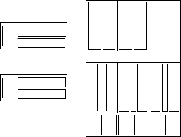
Racking Configurations
There are various equipment racking configurations available to customers. The following section includes
sketches which depict many of the racking alternatives.
GTR 8000 Expandable Site Sub-system Layout
PS #1
PS #2
PS #3
PS #4
PS #5
PS #6
PA #1
PA #2
PA #3
PA #4
PA #5
PA #6
XCVR #1
XCVR #2
XCVR #3
XCVR #4
XCVR #5
XCVR #6
SC #1
SC #2
ALARM
Bay #1 Bay #2 Bay #3
PS #1
PS #2
PS #3
PS #4
PS #5
PS #6
PA #1
PA #2
PA #3
PA #4
PA #5
PA #6
XCVR #1
XCVR #2
XCVR #3
XCVR #4
XCVR #5
XCVR #6
SC #1
SC #2
ALARM
Bay #1 Bay #2 Bay #3
Fan Module #1 serves PA Bay #1
Fan Module #2 serves PA Bay #2
Fan Module #3 serves PA Bay #3
Fan Module #4 serves XCVR Bay #1
Fan Module #5 serves XCVR Bay #2
Fan Module #6 serves XCVR Bay #3
Fan Module #1 serves PA Bay #1
Fan Module #2 serves PA Bay #2
Fan Module #3 serves PA Bay #3
Fan Module #4 serves XCVR Bay #1
Fan Module #5 serves XCVR Bay #2
Fan Module #6 serves XCVR Bay #3
Configuration Layout
PA
XCVR
PS
Base Radio
PA
XCVR
PS
XCVR #2
PS
XCVR #1
XCVR #2XCVR #2
PS
Receive Only Base Radio
GTR 8000 Expandable Site Sub-system Layout
PS #1
PS #2
PS #3
PS #4
PS #5
PS #6
PA #1
PA #2
PA #3
PA #4
PA #5
PA #6
XCVR #1
XCVR #2
XCVR #3
XCVR #4
XCVR #5
XCVR #6
SC #1
SC #2
ALARM
Bay #1 Bay #2 Bay #3
PS #1
PS #2
PS #3
PS #4
PS #5
PS #6
PA #1
PA #2
PA #3
PA #4
PA #5
PA #6
XCVR #1
XCVR #2
XCVR #3
XCVR #4
XCVR #5
XCVR #6
SC #1
SC #2
ALARM
Bay #1 Bay #2 Bay #3
Fan Module #1 serves PA Bay #1
Fan Module #2 serves PA Bay #2
Fan Module #3 serves PA Bay #3
Fan Module #4 serves XCVR Bay #1
Fan Module #5 serves XCVR Bay #2
Fan Module #6 serves XCVR Bay #3
Fan Module #1 serves PA Bay #1
Fan Module #2 serves PA Bay #2
Fan Module #3 serves PA Bay #3
Fan Module #4 serves XCVR Bay #1
Fan Module #5 serves XCVR Bay #2
Fan Module #6 serves XCVR Bay #3
Configuration Layout
PA
XCVR
PS
Base Radio
PA
XCVR
PS
XCVR #2XCVR #2
PS
XCVR #1XCVR #1
XCVR #2XCVR #2
PS
Receive Only Base Radio
APPLICANT: MOTOROLA SOLUTIONS EQUIPMENT TYPE: ABZ89FC5823B
109AB-5823B
User / Operational Manual
Functional Description / Operation of Modules (Draft)
EXHIBIT D1-6
Functions of the GTR 8000 Base Radio Modules
The following lists GTR 8000 Base Radio modules:
Transceiver (XCVR) module (with or without transceiver option card)
Power amplifier module (not applicable in a GPW 8000 Receiver)
Fan module
Power supply module
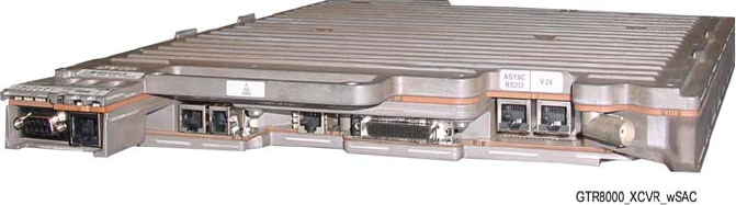
Transceiver Module Overview
The transceiver module provides the control, exciter, receiver, and optional transceiver option card for the base
radio/receiver.
Transceiver Module (Front View)
The transceiver generates the station reference, which typically needs to be locked on to one of many possible external
sources. The external source can be either the site controller TDM clocks or the external reference operating at 5 or 10
MHz. An internal frequency reference operating at 10 MHz is available in an optional transceiver option card.
The transceiver SPI bus allows communication with its receiver and exciter circuitry, as well as the power supply and power
amplifier modules.
There are two or three circuit boards in the transceiver:
• Transceiver Control Board: Performs the control management, digital signal processing, and transmit and receive
data formatting for the base radio.
• Transceiver RF Board: Contains DC power conversion/regulation and performs receiver and exciter functions.
• Transceiver Option Card: An optional board that attaches to the control board. Provides an internal 10 MHz
frequency reference. For conventional base radio/receiver operation it also provides the analog interfaces and wildcard I/Os.
The transceiver option card requires an internal frequency reference oscillator alignment at different intervals that is
mandated by its category and frequency band. See Base Radio Service Help > Service Screens > Alignment Screens in the
CSS Online Help for the alignment procedures and mandated intervals. The transceiver option card is available in two
categories:
• OCXO (Oven Controlled Crystal Oscillator) – operates at 0.1 ppm which is inclusive to temperature and aging.
The OCXO Transceiver Option Card is available in 700/800 MHz, UHF R1/R2, and VHF frequency bands.
• TCXO (Temperature Compensated Crystal Oscillator) – operates at 1.5 ppm, of which 0.5 ppm is allocated to
temperature and 1.0 ppm is allocated to aging. Reference precision with the TCXO is traded for lower power consumption.
The TCXO mandates shorter maintenance intervals. The TCXO transceiver option card is available in UHF R1/R2
frequency bands. The TXCO is only available for non-simulcast conventional systems.
Transceiver Control Board
The main operating software for the base radio is loaded in the transceiver (XCVR) control section. As the main manager
for the base radio, the XCVR control board provides operational control over the other station modules. It handles three
types of information flow, in the following ways:
• Serves as a gateway between the network and RF functionality, by distributing the RF payload to and from the
network.
• Supports operational and diagnostic functions with digital control data (for example: site information, channel
assignments, and identification numbers for call processing).
• Ensures the flow of other network management configuration information.
APPLICANT: MOTOROLA SOLUTIONS EQUIPMENT TYPE: ABZ89FC5823B
109AB-5823B
User / Operational Manual
Functional Description / Operation of Modules (Draft)
EXHIBIT D1-6
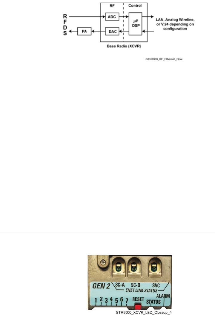
The following figure shows the information flow through the transceiver control and RF sections for trunked and
conventional operation.
Transceiver Control Board Information Flow
Transceiver RF Board
In addition to DC power conversion/regulation, the XCVR RF board provides circuitry for the following exciter and
receiver functions.
Exciter
The exciter on the XCVR RF board provides the transmitter functions for the base radio. The exciter circuitry generates a
low-level, modulated RF signal that passes to the power amplifier. It supports various modulation types as well as
bandwidths up to 25 kHz, through software programming.
The exciter also provides a controlled output power level to the power amplifier.
Receiver
The receiver provides either single receiver input or dual (HPD or TDMA) receiver inputs for dual diversity. The receiver
also provides enhanced diagnostic capabilities using an on board noise source generator. It includes a wide tuning range
(electronic varactor-tuned) preselector. The preselector is electronically tuned to the desired receive frequency anywhere
between 792–825 MHz, UHF R1 380–435 MHz, UHF R2 435–524 MHz, or VHF 136–174 MHz.
Transceiver External Interfaces
The transceiver external interfaces include seven external ports, a switch and LEDs. If a transceiver option card is part of
the transceiver, there are four additional external ports. See 3.4.7 Connections – Front, page 3-28 for the port connections.
See 10.1 LEDs, page 10-1 for information on the LEDs.
Transceiver Switch
There is one multifunction Reset switch on the front of the transceiver module, accessible through the drop-down door to
the left of the fans. The Reset switch has two functions:
User Action Result
Press switch for less than 1 second Service Mode (LED3 lights amber)
Press switch for more than 3 seconds Transceiver Control Module Reset
Transceiver Reset Switch (viewable through drop-down door)
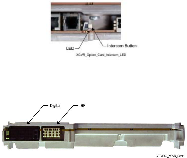
Transceiver Option Card Intercom Button
APPLICANT: MOTOROLA SOLUTIONS EQUIPMENT TYPE: ABZ89FC5823B
109AB-5823B
User / Operational Manual
Functional Description / Operation of Modules (Draft)
EXHIBIT D1-6
There is one intercom button on the front of the transceiver option card, accessible behind the fan module. Pressing the
intercom button toggles the intercom function between the ON and OFF states
Transceiver Option Card Intercom Button (behind fan module)
Transceiver Ports (Rear)
The transceiver interconnects to the backplane using a120-pin HVDML digital connector and 8-pack RF connector, as
shown in the figure. These connections handle multiple signals including power supply communications, power amplifier
communications, fan interface, and peripheral interface. The digital connection receives alarm data and the site
controllers' TDM signals, which are used to pass reference and control data to the base radio.
Transceiver Module (Backplane Connections)
• Single Receiver Input: An RJ-45 Ethernet port on the base radio backplane is cabled to a site LAN switch for this
channel. The backplane also provides an RF connection to the transceiver for receive (Rx) path A.
• Dual Receiver Input: RJ-45Ethernet ports on the base radio backplane are cabled to corresponding ports on the site
controller backplanes (HPD). The backplane also provides RF connections to the transceiver for receive (Rx) paths A and B
(HPD and TDMA).
APPLICANT: MOTOROLA SOLUTIONS EQUIPMENT TYPE: ABZ89FC5823B
109AB-5823B
User / Operational Manual
Functional Description / Operation of Modules (Draft)
EXHIBIT D1-6
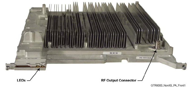
Function of the Power Amplifier Module
Note: The PA module is not applicable in a GPW 8000 Receiver.
The power amplifier (PA) is a forced convection-cooled RF power amplifier. It accepts a low-level modulated RF signal
from the transceiver module, and amplifies it for transmission through the site transmit antenna. Also, to complete the
Cartesian correction loop (linearization method), it provides a low level RF feedback signal to the transceiver module to
achieve the required transmitter linearity.
Transmit power output can be set using Configuration/Service Software (CSS). See 4.4.10 Configuring Tx Power Values
and Battery Type, page 4-32.
The power amplifier also performs functions related to the fan module, including reporting of the fan module status and
supplying power to the fan power bus.
The power amplifier is comprised of six internal modules:
• Core Board
• Converter Board
• Driver Amplifier Board
• Final Amplifier Board
• Distribution Board
• Output Circuitry
Power Amplifier Module
APPLICANT: MOTOROLA SOLUTIONS EQUIPMENT TYPE: ABZ89FC5823B
109AB-5823B
User / Operational Manual
Functional Description / Operation of Modules (Draft)
EXHIBIT D1-6
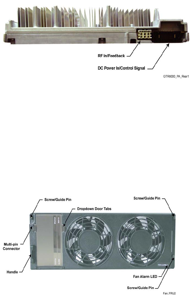
Power Amplifier Input / Output Connections
There are three electrical connection assemblies on the power amplifier:
• RF output (front QN "quick-N" connector) on front of power amplifier module. This is cabled to the N-type female
bulkhead connection at the rear of the base radio housing
• DC power supply/control signal (backplane connection)
• RF input/feedback (backplane connection)
Power Amplifier (Backplane Connections)
Function of the Fan Module
The fan module provides intermittent forced air cooling for the power amplifier and transceiver modules. The fans are
controlled by a thermostat in the modules behind the fan module. The fan module houses two 119 mm axial fans which
deliver a total of approximately 160 cubic feet per minute of airflow. Nominal fan speed is 4100 revolutions per minute.
Each fan has a built-in speed sensor which turns on the red Fan Alarm LED if the fan speed for either fan falls below
30% of the rated speed.
If the fan module is used for the Power Efficiency Package, the following must be configured in the CSS in order to take
full advantage of the Power Efficiency Package:
• Optional fan holdover time (length of time the base radio/receiver fan stays ON after transmission).
• Disabling one of the fans within the fan module. See 9.3.1 How To Replace the Fan Assembly, page 9-11 for
instructions on how to disable one of the fans.
• Configuring the base radios Tx Power Out in the CSS should be limited to 50 W.
The fan module connects to the base radio backplane through a 4pin port on the front of the base radio chassis. The power
supply module has its own fan which provides independent airflow.
Fan Module
APPLICANT: MOTOROLA SOLUTIONS EQUIPMENT TYPE: ABZ89FC5823B
109AB-5823B
User / Operational Manual
Functional Description / Operation of Modules (Draft)
EXHIBIT D1-6
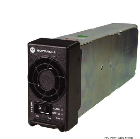
Function of the Power Supply Module
The power supply, with front-to-rear air flow, operates from either an AC or DC input and provides the DC operating
voltage for the base radio. However, the power supply prioritizes an AC source (if present) over that of a DC source.
If the power supply module is used for the Power Efficiency Package, the power supply must be used in DC mode in
order to obtain the 35 W standby power consumption performance.
When operating from an AC source (90 to 264 VAC, 47-63 Hz), the supply generates two DC output voltages of 29 V
with respect to output ground. The power supply automatically adjusts to AC input ranges and supplies a steady output.
In AC mode, the power supply provides a separate battery charger which can be used to maintain the charge on a 48 VDC
nominal system, positive or negative ground, if installed. The supply generates two DC output voltages of 29 V with
reference to output ground, when operating from a DC source (43.2 VDC to 60VDC maximum, positive or negative
ground. This voltage limit includes consideration of the battery charging "float voltage" associated with the intended
supply system, regardless of the marked power rating of the equipment.
The battery charger is not usable when operating from a DC input power source. This DC source must be located in the
same building as the base radio / repeater, and it must meet the requirements of a SELV circuit.
The power supply contains several switching-type power supply circuits as follows:
• Power factor correction circuitry
• Battery charging circuitry
• Diagnostics and monitoring circuitry
The power supply controls its own continuously running fan, changing its speed to fast or slow as needed.
GTR 8000 Base Radio: If the power supply module is used for the Power Efficiency Package, the power supply fan does
not run below a 40 °C air inlet temperature in DC mode with the transmitter in a de-keyed state.
GPW 8000 Receiver: If the power supply module is used for the Power Efficiency Package, the power supply fan does
not run below a 40 °C air inlet temperature.
Power Supply Module