Motorola Solutions 89FT4840 MOSCAD-L P44-UHF1 FLN2582A , SCADA Terminal User Manual Chapter Error
Motorola Solutions, Inc. MOSCAD-L P44-UHF1 FLN2582A , SCADA Terminal Chapter Error
Contents
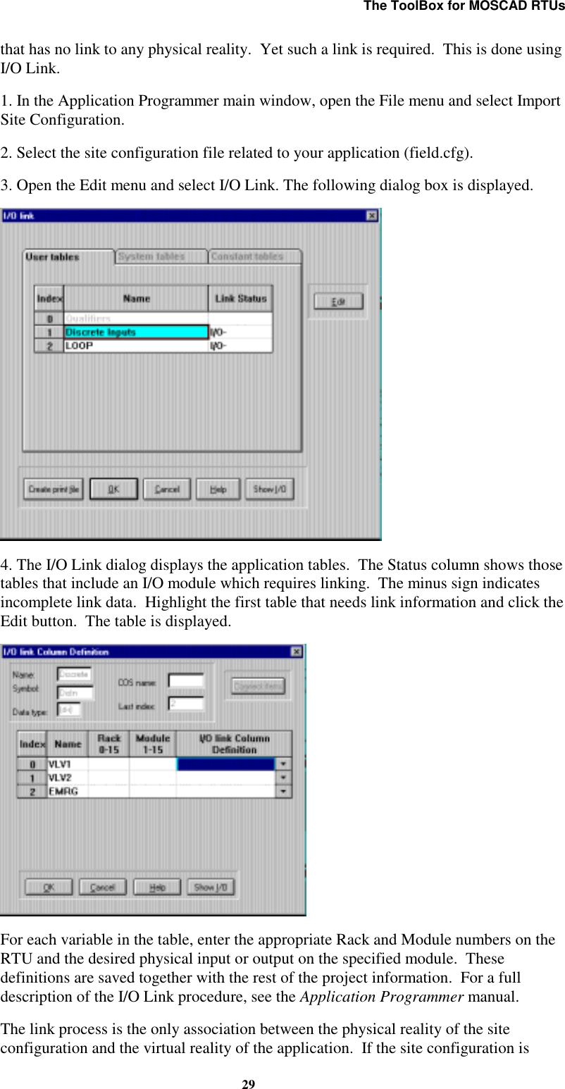
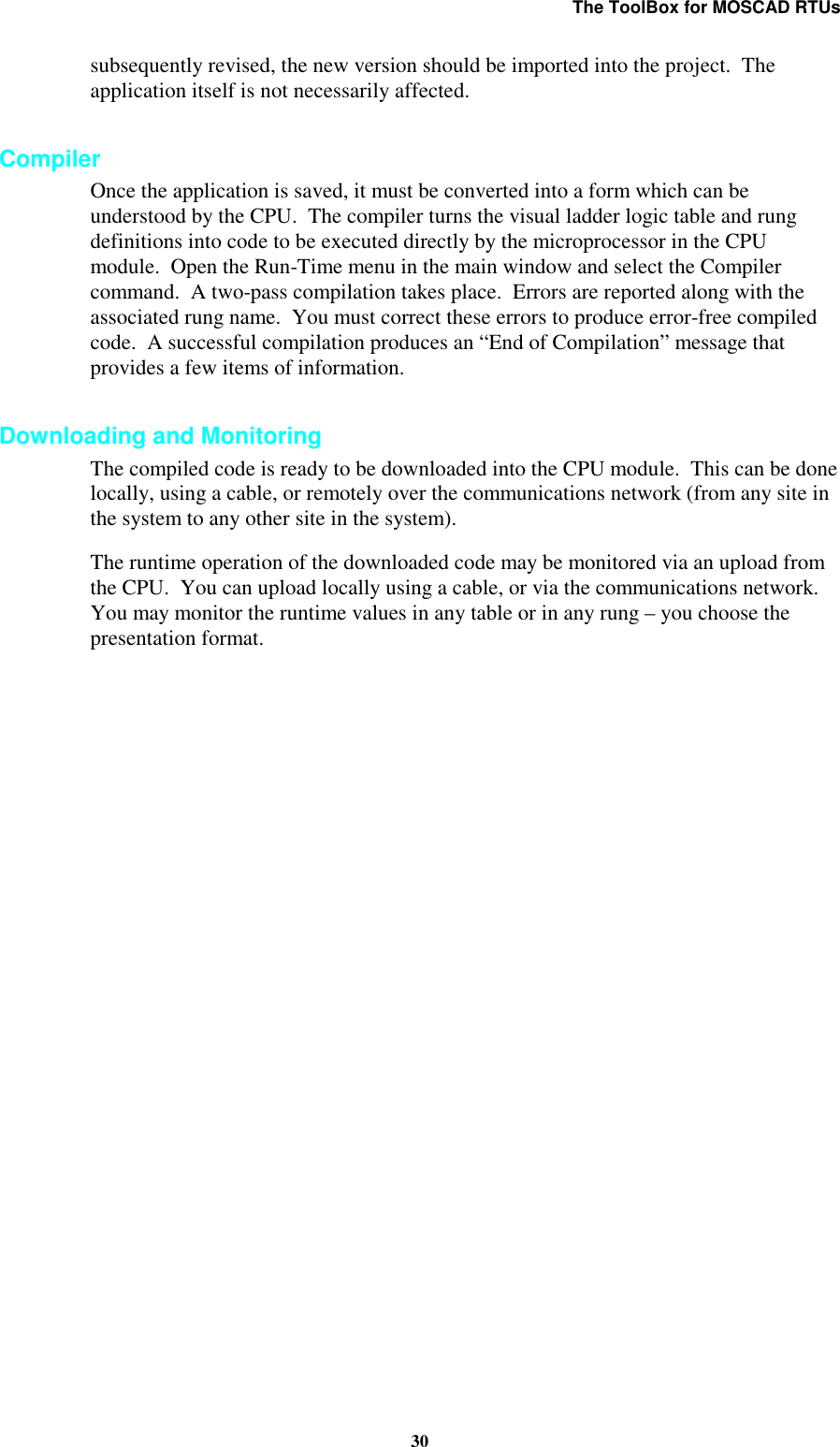
- 1. programmers manual
- 2. users and installation guide
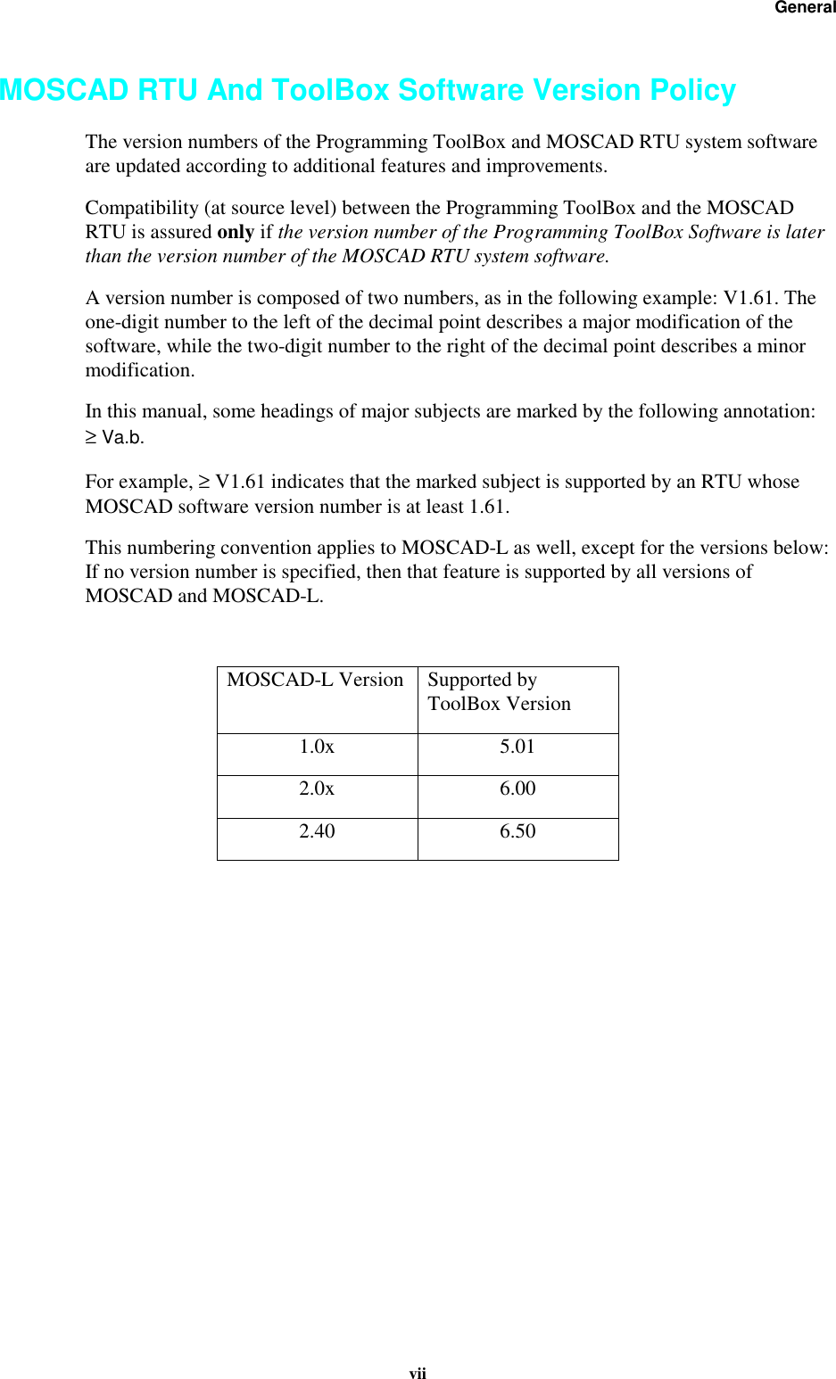
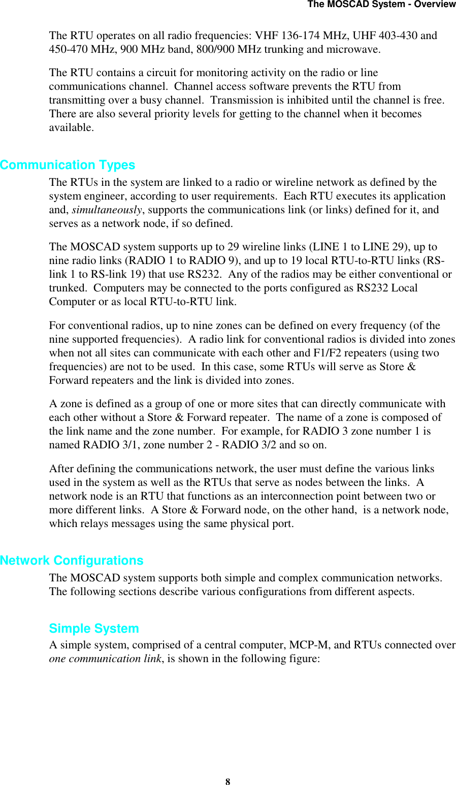
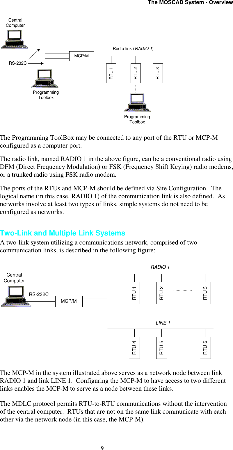
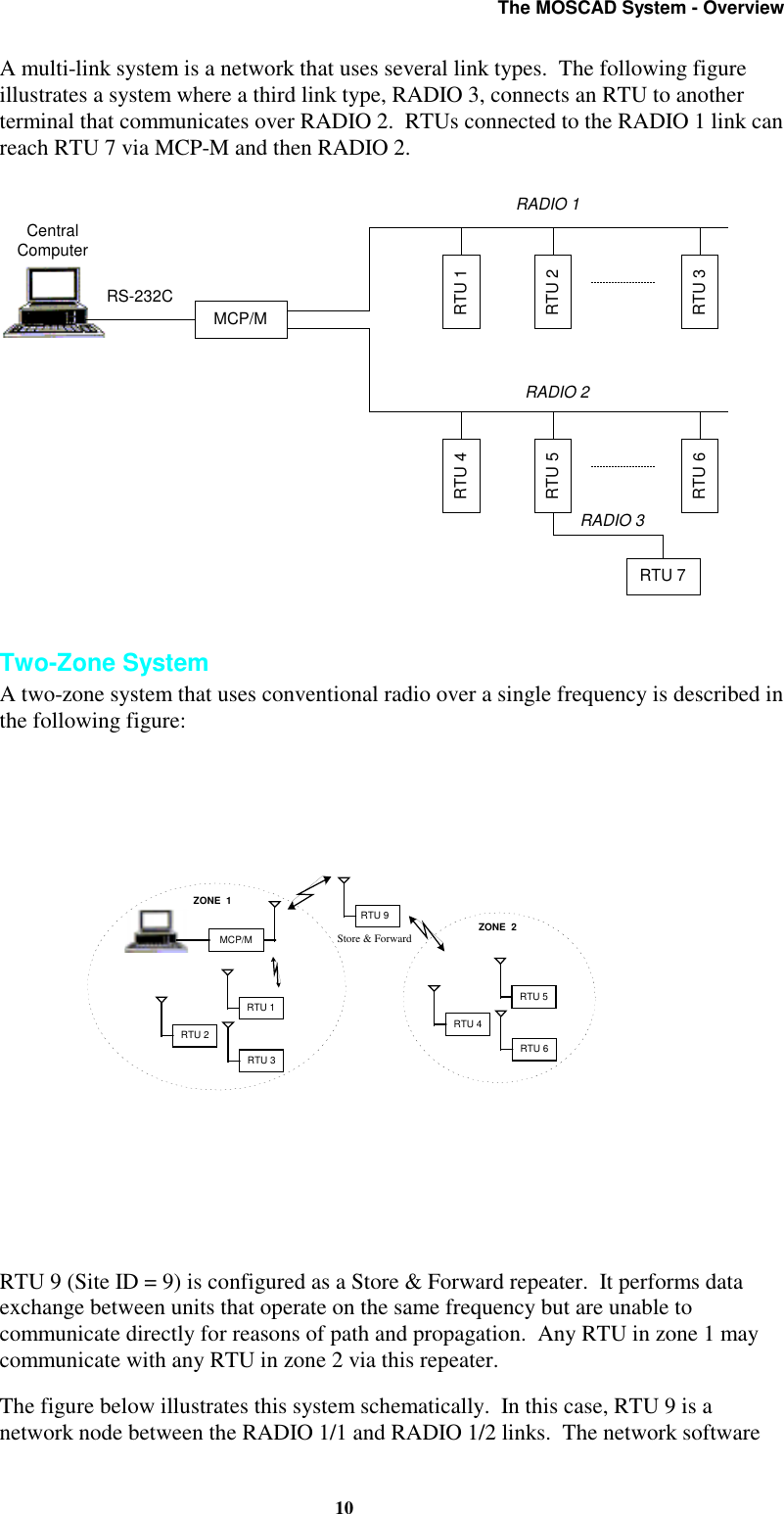
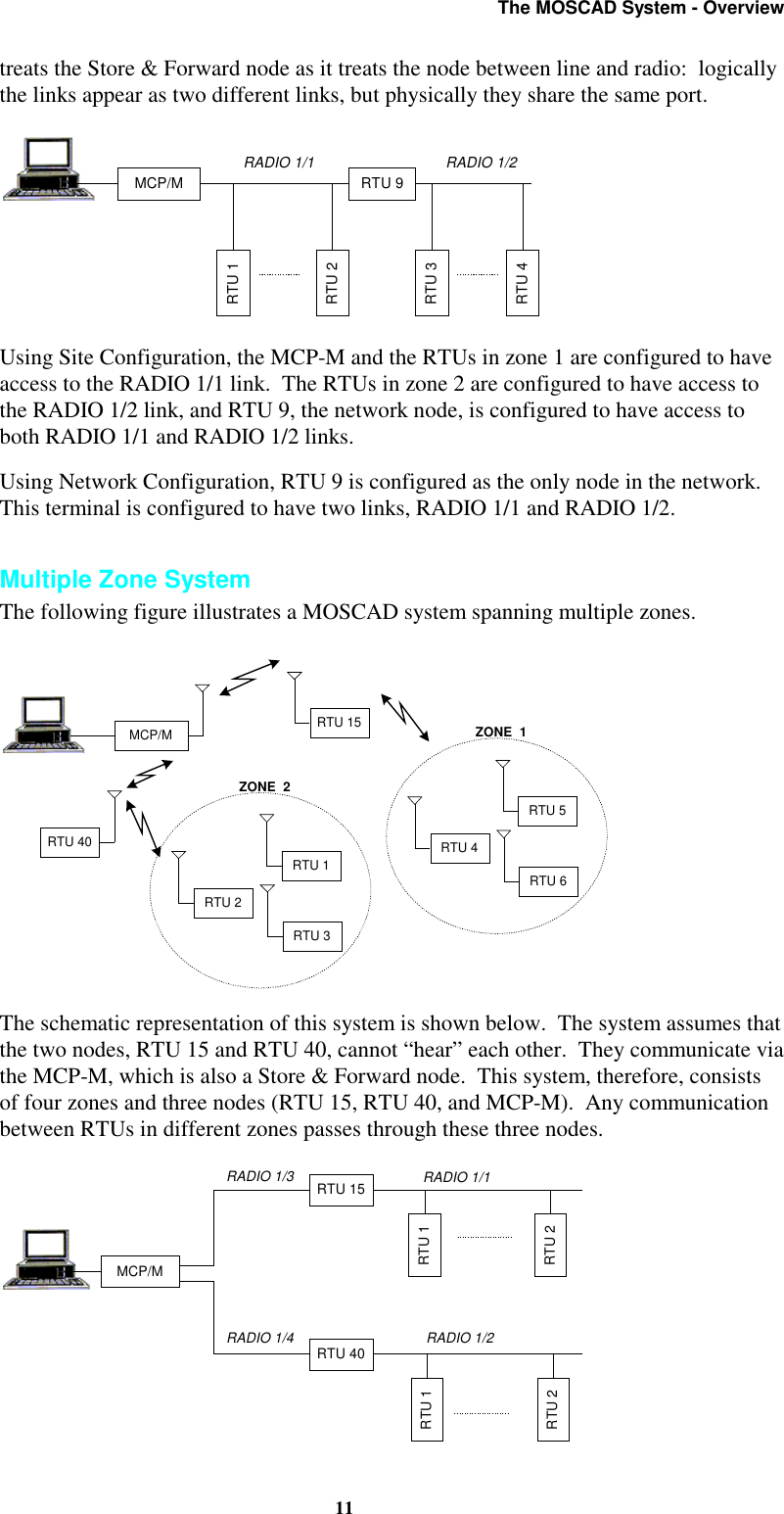
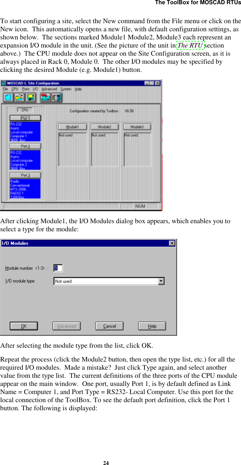
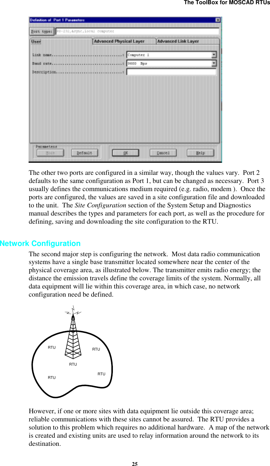
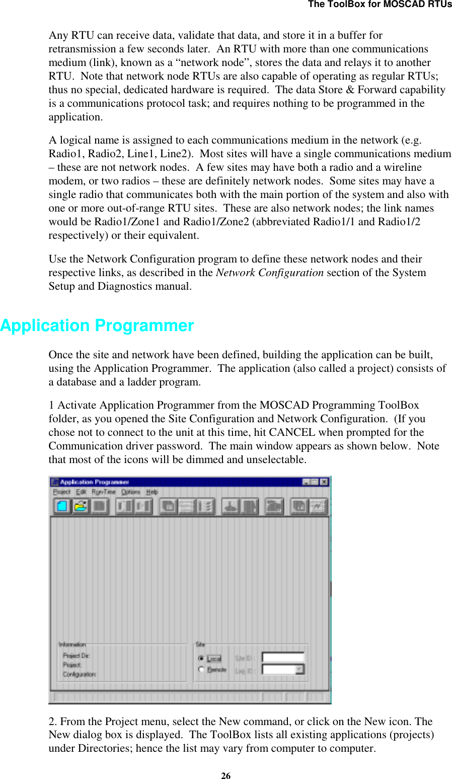
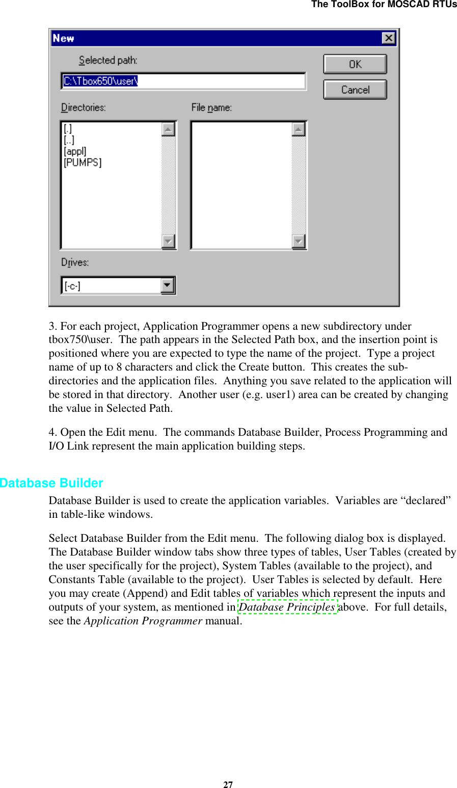
programmers manual