Motorola Solutions 89FT4855 Astro XTS 5000 User Manual 94C27 B XTS5000 MIII
Motorola Solutions, Inc. Astro XTS 5000 94C27 B XTS5000 MIII
Contents
- 1. Draft Users Manual
- 2. Safety Section of User Manual
- 3. Amended Safety Booklet
Draft Users Manual
ASTRO® XTS™ 5000
Digital Portable Radio, Model III
Quick Reference Card
Product Safety and RF Exposure Compliance
ATTENTION!
This radio is restricted to occupational use only to satisfy FCC RF
energy exposure requirements. Before using this product, read the
RF energy awareness information and operating instructions in the
Product Safety and RF Exposure booklet enclosed with your radio
(Motorola Publication part number 68P81095C98) to ensure
compliance with RF energy exposure limits.
Write your radio’s programmed features on the dotted lines.
Radio On/Off
Zones/Channels
Receive/Transmit
Send Emergency Alarm
Send Emergency Call
Send Silent Emergency Alarm
Before using this product, read the operating instructions
for safe usage contained in the Product Safety and RF
Exposure booklet enclosed with your radio.
!
C a u t i o n
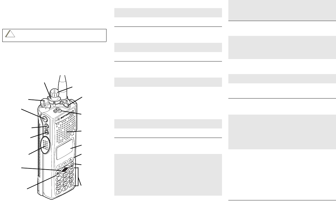
16-Position
Select Knob
_ _ _ _ _ _ _
Speaker/Mic
Top Button
_ _ _ _ _ _ _
Concentric
Switch
_ _ _ _ _ _
Display
Keypad
Menu Select
Buttons
App Button
(for future
use)
Top Side
Button
_ _ _ _ _ _ _
On/Off/
Volume Knob
Side Button 1
_ _ _ _ _ _ _
Side Button 2
_ _ _ _ _ _ _
PTT Button
3-Position
Switch
_ _ _ _ _ _ _
4-Way
Navigation
Button
Home Button
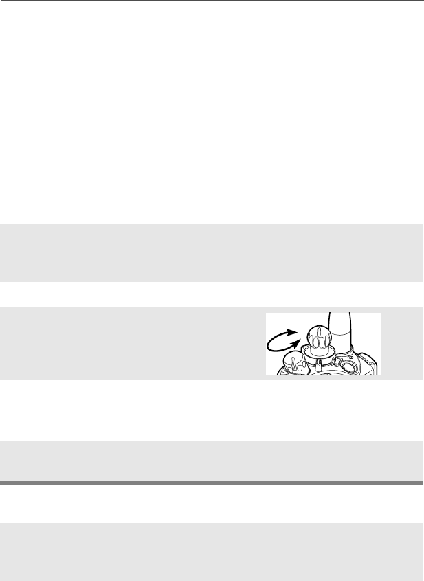
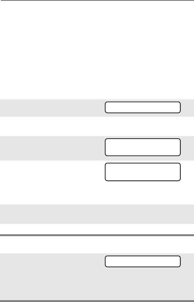
1On - On/Off/Volume knob clockwise.
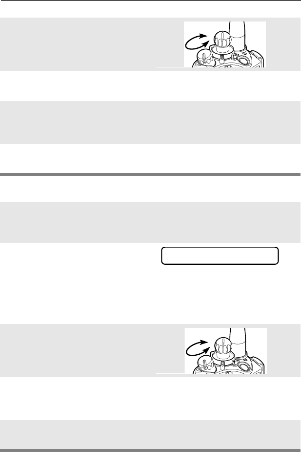
2Off - On/Off/Volume knob counterclockwise.
1 Zone - Zone switch to desired zone.
2 Channel - Channel switch to desired channel.
1 Radio on and select zone/channel.
2 Listen for a transmission.
- or -
Press and hold Volume Set button.
- or -
Press Monitor button and listen for activity.
3 Adjust volume, if necessary.
4Press PTT to transmit; release to receive.
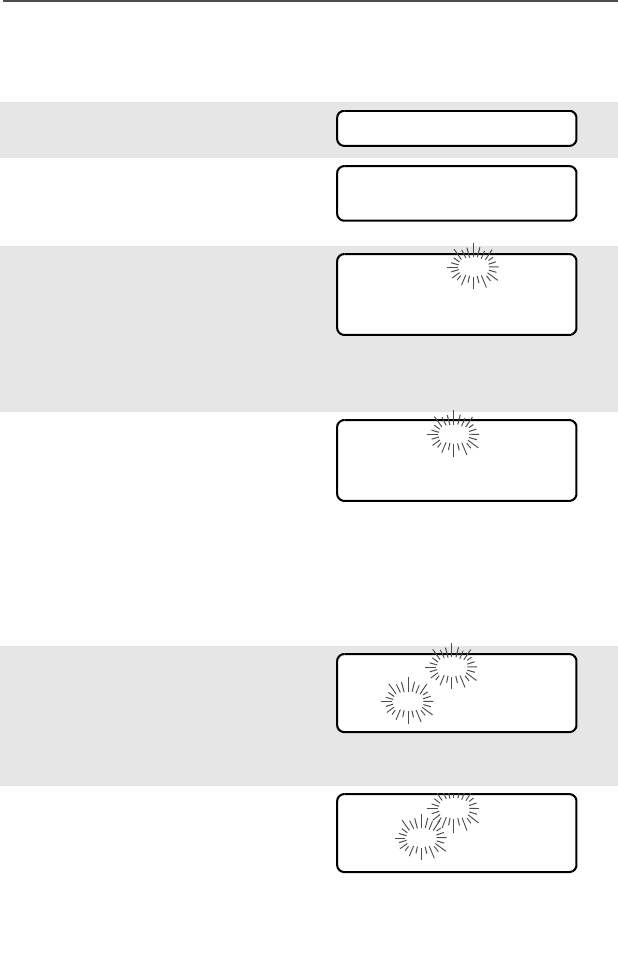
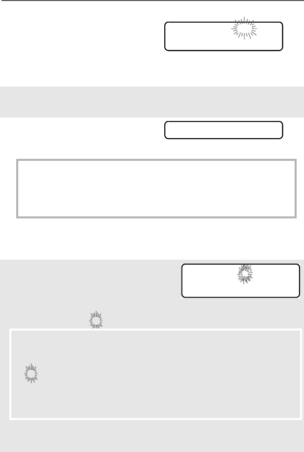
Radio on and press Emergency button.
Display shows current zone/channel, and
EMERGENCY. Red LED lights; you hear short,
medium-pitched tone.
Note: To exit emergency at any time, press
and hold Emergency button.
When acknowledgment is received, you hear
four beeps; alarm ends; radio exits emer-
gency.
1 Radio on and press Emergency button.
Note: To exit emergency at any time, press
and hold Emergency button.
2 Press and hold PTT. Announce your
emergency into the microphone.
3 Release PTT to end call.
4 Press and hold Emergency button to exit
emergency.
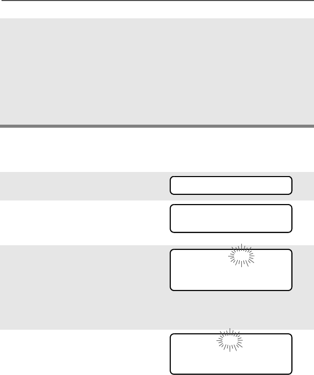
1 Radio on and press Emergency button.
Display does not change; you see no LED;
you hear no tone.
Note: To exit emergency at any time, press
and hold Emergency button.
2 Silent emergency continues until you:
• Press and hold Emergency button to exit
emergency state.
- or -
• Press and release PTT to exit silent
emergency and enter regular emergency
(alarm, call, or alarm with call).
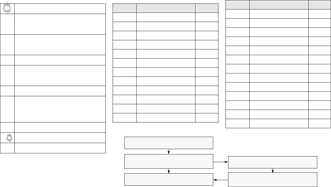
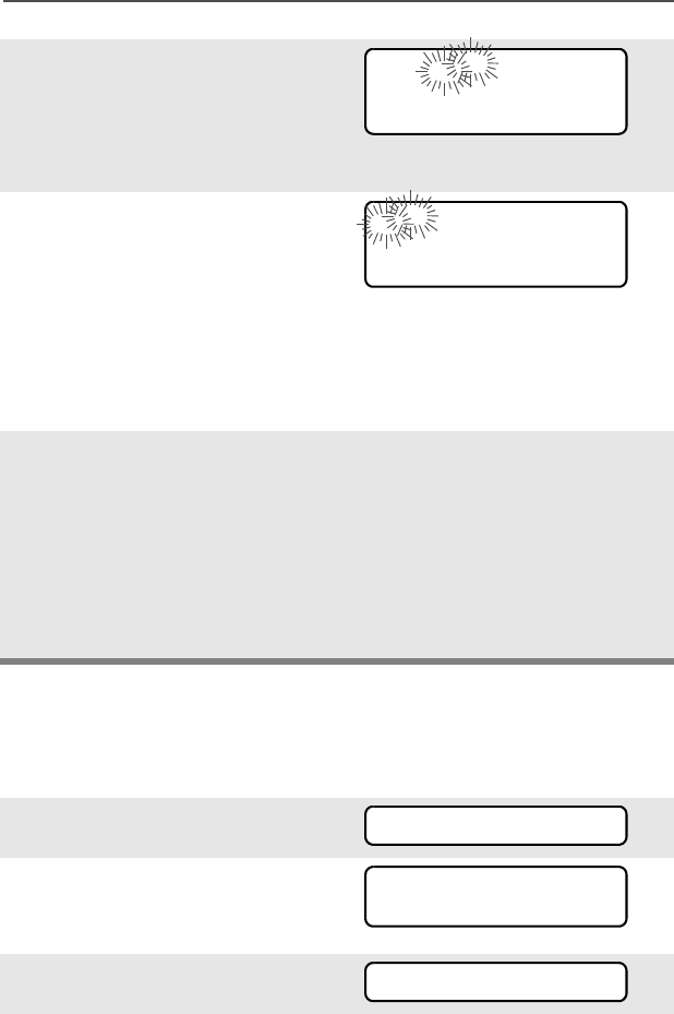
Display Status Symbols Menu Entries (Use With Menu Navigation)
mReceiving an individual call
pThe radio is in the view or program mode;
On Steady = view mode; Flashing =
program mode
sReceived signal strength for the current
site (trunking only). The more stripes in the
symbol, the stronger the signal.
bFlashes when the battery is low.
rYou are talking directly to another radio or
through a repeater; On = direct;
Off = repeater
CThis channel is being monitored.
cYour radio is in secure operation;
On = secure operation;
Off = clear operation; Flashing =
receiving an encrypted voice call
TThe radio is scanning a scan list
SPriority 1 Channel during scan
SPriority 2 Channel during scan
Entry Menu Selection Page
BATT Smart Battery 16
CALL Private Call/Selective Call 59/63
CHAN Select a Channel 22
CLCK Set the Time and Date 95
DIR Repeater/Direct 74
ERAS Key Zeroization 82
KEY Key Selection 79
KSET Keyset Selection 80
LOGF Radio Lock 31
MUTE Keypad Mute 32
NAME Text Select 42
NUM Number Select 41
Entry Menu Selection Page
PAGE Call Alert Page 67
PHON Phone 55
PROG Editing 41
PSWD Password 30
PWR TX Power Level 27
REKY Rekey Request 85
RPGM Reprogram Request 88
SCAN Scan On/Off 51
SITE Site Lock/Unlock 92
STS Status Call 72
TGRP Talkgroup Call 70
VIEW View a List 40
ZONE Select a Zone 21
Menu Navigation
U to find Menu Entry
D, or E, or F directly below
Menu Entry to select
h to exit
V or U to scroll through sub-list
D, or E, or F directly below
Menu Entry to select

ASTRO® XTS™ 5000
Digital Portable Radio
Model III
User Guide
68P81094C27-C
Motorola, Inc.
8000 West Sunrise Blvd.
Ft. Lauderdale, FL 33322

Product Safety and RF Exposure Compliance
ATTENTION!
This radio is restricted to occupational use only to satisfy FCC RF energy
exposure requirements. Before using this product, read the RF energy
awareness information and operating instructions in the Product Safety and RF
Exposure booklet enclosed with your radio (Motorola Publication part number
68P81095C98) to ensure compliance with RF energy exposure limits.
Computer Software Copyrights
The Motorola products described in this manual may include copyrighted Motorola
computer programs stored in semiconductor memories or other media. Laws in the
United States and other countries preserve for Motorola certain exclusive rights for
copyrighted computer programs, including, but not limited to, the exclusive right to copy
or reproduce in any form the copyrighted computer program. Accordingly, any
copyrighted Motorola computer programs contained in the Motorola products described
in this manual may not be copied, reproduced, modified, reverse-engineered, or
distributed in any manner without the express written permission of Motorola.
Furthermore, the purchase of Motorola products shall not be deemed to grant either
directly or by implication, estoppel, or otherwise, any license under the copyrights,
patents or patent applications of Motorola, except for the normal non-exclusive license
to use that arises by operation of law in the sale of a product.
Documentation Copyrights
No duplication or distribution of this document or any portion thereof shall take place
without the express written permission of Motorola. No part of this manual may be
reproduced, distributed, or transmitted in any form or by any means, electronic or
mechanical, for any purpose without the express written permission of Motorola.
Disclaimer
The information in this document is carefully examined, and is believed to be entirely
reliable. However, no responsibility is assumed for inaccuracies. Furthermore, Motorola
reserves the right to make changes to any products herein to improve readability,
function, or design. Motorola does not assume any liability arising out of the
applications or use of any product or circuit described herein; nor does it cover any
license under its patent rights, nor the rights of others.
MOTOROLA, the Stylized M Logo and ASTRO are registered in the U.S. Patent &
Trademark Office. All other product or service names are the property of their
respective owners.
P25 radios contain technology patented by Digital Voice Systems, Inc.
© Motorola, Inc. 2002. All Rights Reserved. Printed in the U.S.A. 9/02.
Before using this product, read the operating instructions for safe
usage contained in the Product Safety and RF Exposure booklet
enclosed with your radio.
!
C a u t i o n

ASTRO Digital XTS 5000 Model III iii
Contents
Product Safety and RF Exposure Compliance ................................. ii
Computer Software Copyrights ......................................................... ii
Documentation Copyrights ................................................................ ii
Disclaimer ......................................................................................... ii
General Radio Operation . . . . . . . . . . . . . . . . . . . . . . . 1
Notations Used in This Manual ......................................................... 1
Your XTS 5000 Model III Radio ......................................................... 2
Physical Features of the XTS 5000 Model III Radio ......................... 3
Programmable Controls .................................................................... 3
Display .............................................................................................. 4
Backlight ..................................................................................... 5
Status Symbols ........................................................................... 5
Menu Entry (Softkey) .................................................................. 7
Menu Select Buttons .................................................................. 7
Menu Entry Features .................................................................. 8
Home Button ............................................................................... 8
App Button .................................................................................. 8
4-Way Navigation Button ............................................................ 9
Keypad .............................................................................................. 9
LED Indicators ................................................................................ 10
Alert Tones ...................................................................................... 11
Standard Accessories ..................................................................... 14
Battery ...................................................................................... 14
Smart Battery Status ................................................................ 16
Antenna .................................................................................... 17
Belt Clip .................................................................................... 18
Universal Connector Cover ...................................................... 19
Radio On and Off ............................................................................ 20
Turn the Radio On .................................................................... 20
Turn the Radio Off .................................................................... 20
Zones and Channels ....................................................................... 21
Select a Zone ........................................................................... 21
Select a Channel ...................................................................... 22
Receive / Transmit .......................................................................... 24
Without Using the Volume Set and Monitor Buttons ................ 24
Use the Preprogrammed Volume Set Button ........................... 24
Use the Preprogrammed Monitor Button .................................. 25
Conventional Mode Operation .................................................. 26

iv
Contents
Common Radio Features . . . . . . . . . . . . . . . . . . . . . . 27
Selectable Power Level ...................................................................27
Use the Menu ............................................................................27
Use the Preprogrammed Transmit Power Level Switch ...........28
Radio Lock .......................................................................................29
Unlock Your Radio ....................................................................29
Change Your Password ............................................................30
Enable or Disable the Radio Lock Feature
(Secure Radios Only) ............................................................31
Mute or Unmute Keypad Tones .......................................................32
Use the Menu ............................................................................32
Use the Preprogrammed Keypad Mute Button .........................32
Conventional Squelch Operation .....................................................33
Analog Options .........................................................................33
Digital Options ...........................................................................33
PL Defeat .........................................................................................34
Time-out Timer ................................................................................35
Emergency ......................................................................................36
Send an Emergency Alarm .......................................................36
Send an Emergency Call ..........................................................37
Send a Silent Emergency Alarm ...............................................38
Emergency Keep-Alive .............................................................39
Lists .................................................................................................40
View a List .................................................................................40
Scan List Empty .......................................................................40
Edit a Call, Page, or Phone List Number ..................................41
Edit a Call, Page, or Phone List Name .....................................42
Edit a Scan List .........................................................................43
Scan ................................................................................................51
Turn Scan On or Off ..................................................................51
Delete a Nuisance Channel ......................................................52
Conventional Scan Only ...........................................................53
Telephone Calls (Trunking Only) .....................................................54
Quick Access (One-Touch) .......................................................54
Answer a Phone Call ................................................................55
Initiate a Phone Call ..................................................................55
Select a Phone Number ............................................................56
Make a Phone Call ...................................................................56
Private Calls (Trunking Only) ...........................................................58
Quick Access (One-Touch) .......................................................58

ASTRO Digital XTS 5000 Model III v
Contents
Answer a Private Call ............................................................... 59
Initiate a Private Call ................................................................. 59
Select an ID Number ................................................................ 60
Make a Private Call .................................................................. 61
Selective Calls (ASTRO Conventional Only) .................................. 62
Quick Access (One-Touch) ...................................................... 62
Answer a Selective Call ............................................................ 62
Initiate a Selective Call ............................................................. 63
Select an ID Number ................................................................ 63
Make a Selective Call ............................................................... 64
Call Alert Paging ............................................................................. 65
Quick Access (One-Touch) ...................................................... 65
Answer a Call Alert Page .......................................................... 66
Initiate a Call Alert Page ........................................................... 67
Select an ID Number ................................................................ 68
Send a Call Alert Page ............................................................. 68
Conventional Talkgroup Calls (Conventional Operation Only) ........ 70
Select a Talkgroup .................................................................... 70
Status Calls (ASTRO 25 Trunking Only) ......................................... 72
Send a Status Call .................................................................... 72
Repeater or Direct Operation .......................................................... 74
Select Repeater or Direct Operation ........................................ 74
Smart PTT (Conventional Only) ...................................................... 76
Special Radio Features. . . . . . . . . . . . . . . . . . . . . . . . 77
Secure Operations .......................................................................... 77
Select Secure Transmissions ................................................... 77
Select Clear Transmissions ...................................................... 77
Managing Encryption ................................................................ 78
Digital PTT ID .................................................................................. 86
Receive ..................................................................................... 86
Transmit .................................................................................... 86
View Your Radio’s ID Number ......................................................... 87
Dynamic Regrouping (Trunking Only) ............................................. 88
Reprogram Request (ASTRO 25 Trunking Only) ..................... 88
Select Enable / Disable ............................................................ 90
Trunking System Controls ............................................................... 91
Failsoft ...................................................................................... 91
Out-of-Range ............................................................................ 91
Site Lock ................................................................................... 92

vi
Contents
Site Trunking .............................................................................93
Site View and Change ..............................................................94
Time and Date .................................................................................95
Helpful Tips . . . . . . . . . . . . . . . . . . . . . . . . . . . . . . . . . 97
Radio Care ......................................................................................97
Things to Avoid .........................................................................97
Cleaning ....................................................................................98
Handling ....................................................................................98
Service .............................................................................................99
Battery ...........................................................................................100
Battery Life ..............................................................................100
Charging the Battery ...............................................................100
Battery Recycling and Disposal ..............................................101
Antenna .........................................................................................103
Radio Operating Frequencies .................................................103
Accessories. . . . . . . . . . . . . . . . . . . . . . . . . . . . . . . . 105
Antennas .......................................................................................105
Batteries and Battery Accessories .................................................105
Carry Accessories .........................................................................106
Belt Clips .................................................................................106
Belt Loops ...............................................................................106
Carry Cases ............................................................................106
Chargers ........................................................................................107
Enhanced and Multi-Unit Line Cords ......................................107
Surveillance Accessories ...............................................................108
Earpieces ................................................................................108
Headsets and Headset Accessories .......................................109
Radio Interface Modules for Ear Microphones ........................109
Speaker, Remote Speaker and Public Safety Microphones ...110
Commport Integrated Microphone/Receivers .........................110
Switches ........................................................................................110
Vehicular Adapters ........................................................................ 111
Accessories .............................................................................111
Allied Models ...........................................................................111


viii
Table 1: Channel Map
Use the chart below to map the channels (Cx) and zones (Zx) for your radio.
Z1 Z2 Z3 Z4 Z5 Z6
C1
C2
C3
C4
C5
C6
C7
C8
C9
C10
C11
C12
C13
C14
C15
C16
ASTRO Digital XTS 5000 Model III 1
General Radio Operation
Notations Used in This Manual
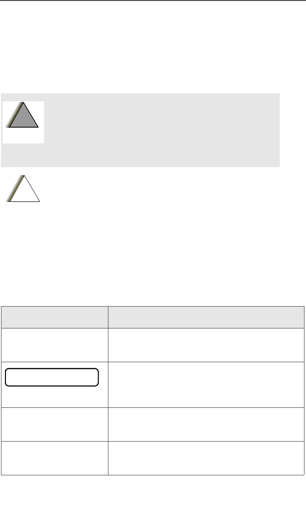
Throughout the text in this publication, you will notice the use of
WARNINGS, Cautions, and Notes. These notations are used to
emphasize that safety hazards exist, and the care that must be taken
or observed.
The following special notations identify certain items:
An operational procedure, practice, or
condition, etc., which may result in injury or
death if not carefully observed.
An operational procedure, practice, or condition,
etc., which may result in damage to the equipment
if not carefully observed.
Note: An operational procedure, practice, or condition,
etc., which is essential to emphasize.
Example Description
Light button or DButtons and keys are shown in bold print or
as a key symbol.
Information appearing on the radio’s
display is shown using the special display
font.
PHONE Menu entries are shown similar to the way
they appear on the radio’s display.
Press UThis means “Press the right side of the
4-way Navigation button.”
!
W A R N I N G
!
!
C a u t i o n
PHONE CALL
2
General Radio Operation
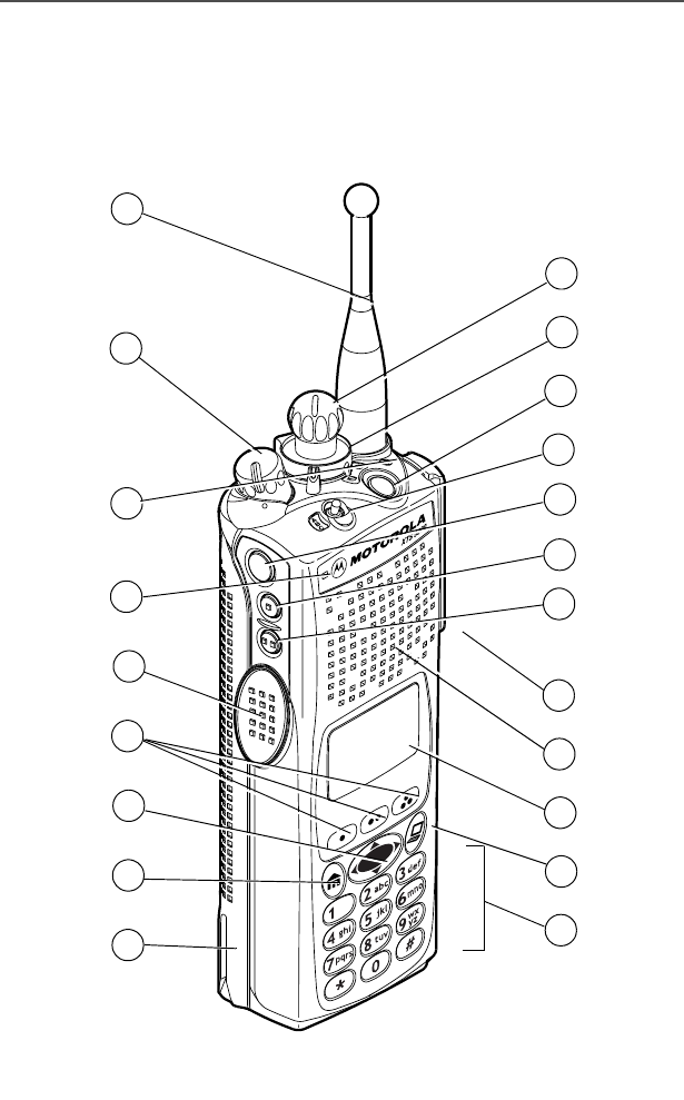
Your XTS 5000 Model III Radio
MAEPF-27193-A
1
21
2
4
5
7
8
10
13
15
16
17
18
3
6
9
12
11
14
19
20

ASTRO Digital XTS 5000 Model III 3
General Radio Operation
Physical Features of the XTS 5000 Model III
Radio
Programmable Controls
The following radio controls can be programmed to operate certain
software-activated features.
The features that can be assigned to these controls by a qualified
radio technician, and the pages where these features can be found
are listed in Table 3 on page 4.
Any references in this manual to controls that are
“preprogrammed” mean that a qualified radio technician must
use the radio’s programming software to assign a feature to a
control.
Table 2: Physical Features
No. Feature Page No. Feature Page
1Antenna 17 8Home Button 8
2On/Off/Volume Control
Knob
20 9Battery 14
3LED 10 10 Keypad 9
4Microphone 11 App Button 8
5PTT (Push-to-Talk)
Button
12 Display 4
6Menu Select Buttons 7 13 Speaker
74-Way Navigation
Button
914 Universal Connector 19
No. Feature No. Feature
15 Side Button 2 19 Top Button
16 Side Button 1 20 2-Position Concentric Switch
17 Top Side (Select) Button 21 16-Position Select Knob
18 3-Position A/B/C Switch
4
General Radio Operation
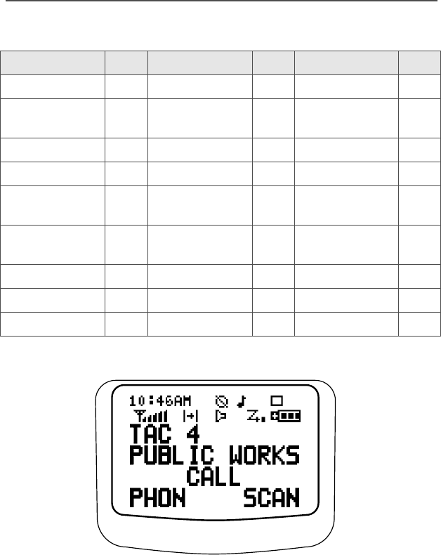
Display
The above screen is typical of what you will see on your radio. The
64 x 96 pixel liquid crystal display (LCD) shows radio status, text, and
menu entries.
Table 3: Programmable Features
Feature Page Feature Page Feature Page
Call Alert 65 Phone 54 Selective Call 62
Call Response 59 PL Defeat 34 Site Lock/
Unlock
92
Channel 22 Private Call 58 Site Search 94
Dynamic Priority 53 Repeater/Direct 75 Smart Battery 16
Emergency 36 Reprogram
Request
89 Status 73
Keypad Mute 32 Scan List
Programming
47 TX Power Level 28
Light 5 Scan On/Off 51 Volume Set 24
Monitor 25 Secure/Clear 77 Zone 21
Nuisance Delete 52 Select 45

ASTRO Digital XTS 5000 Model III 5
General Radio Operation
Backlight
If poor light conditions make the display, keypad, or channel numbers
(around the 16-Position Select knob) difficult to read, turn on the
radio’s backlights by pressing the preprogrammed Light button.
These lights will remain on for a preprogrammed time before they turn
off automatically, or you can turn them off immediately by pressing the
Light button again.
Status Symbols
The top two display rows contain symbols that indicate radio
operating conditions.
Table 4: Status Symbols
Symbol Indication Page No.
mCall Received
Flashes when an Individual Call is
received.
55, 59,
62, 66
p
p
View/Program Mode
The radio is in the view or program mode.
• On steady = view mode
• Flashing = program mode
40-45,
47, 48
s
Received Signal Strength Indication
(RSSI)
The received signal strength for the
current site, for trunking only. The more
stripes in the symbol, the stronger the
signal.
94
b
Battery
• Conventional = flashes when battery
is low
• Smart = the number of bars (0-3)
shown indicates the charge remaining
in your battery; flashes when battery
is low
101

6
General Radio Operation
r
Talkaround
• On = you are talking directly to
another radio, not through a repeater,
during conventional operation only
• Off = you are talking through a
repeater
74
CMonitor (Carrier Squelch)
The selected channel is being monitored
during conventional operation only.
26, 33,
34
c
c
Secure Operation
• On = secure operation
• Off = clear operation
• Flashing = receiving an encrypted
voice call
77
TScan
The radio is scanning a scan list. 44, 46-51
S
(Dot
Flashing)
Priority-One Channel Scan
One channel is assigned as the priority
channel during scan operation. 44, 46-50
S (Dot
Steady)
Priority-Two Channel Scan
Two channels are assigned as the priority
channels during scan operation.
44, 46-50
Table 4: Status Symbols (Continued)
Symbol Indication Page No.
ASTRO Digital XTS 5000 Model III 7
General Radio Operation
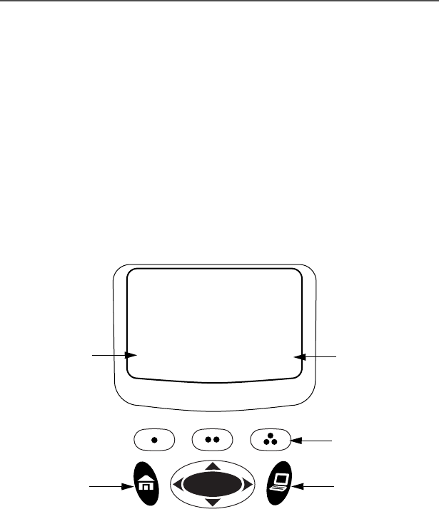
Menu Entry (Softkey)
The bottom row of the display contains one to three menu entries
(also known as softkeys). The menu entries allow you to select one of
several menus to access the radio’s features. The menu entries are
accessed through the Menu Select buttons.
Menu Select Buttons
The Menu Select buttons access the menu entries of features that
have been activated by a qualified radio technician. Your radio may
be programmed differently from the following example, but the display
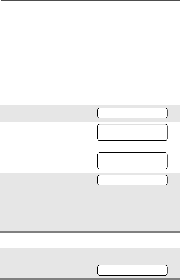
for turning Scan on or off might look like the example below. For
instance, to turn Scan on, press D directly below ON.
ON OFF
SCAN
T
menu entry
3 Menu Select
Buttons
(softkey) menu entry
(softkey)
4-Way Navigation
Button
App
Button
Home
Button

8
General Radio Operation
Menu Entry Features
Home Button
The Home button always returns you to the home (default) display. In
most cases, this is the current mode.
Some radio features that you can edit require saving information in
memory. Pressing the Home button after editing those features
causes information to be saved before going to the home display.
Some features do not require you to press the Home button to go to
the home display. This reduces the required number of key presses.
App Button
Reserved for future use.
Table 5: Menu Entries
Feature Menu
Entry Page Feature Menu
Entry Page
Smart Battery BATT 16 Phone PHON 55
Private Call /
Selective Call
CALL 59/63 Editing PROG 41
Channel Selection CHAN 22 Password PSWD 30
Time/Date CLCK 95 TX Power Level PWR 27
Repeater/Direct DIR 74 Rekey Request REKY 85
Key Zeroization ERAS 82 Reprogram
Request
RPGM 88
Key Selection KEY 79 Scan On/Off SCAN 51
Keyset Selection KSET 80 Site Lock/Unlock SITE 92
Radio Lock LOGF 31 Status Call STS 72
Keypad Mute MUTE 32 Talkgroup Call TGRP 70
Text Select NAME 42 View a List VIEW 40
Number Select NUM 41 Zone Selection ZONE 21
Call Alert Page PAGE 67
ASTRO Digital XTS 5000 Model III 9
General Radio Operation
4-Way Navigation Button
This button is used to scroll through the radio’s lists or items in the
display, or both.
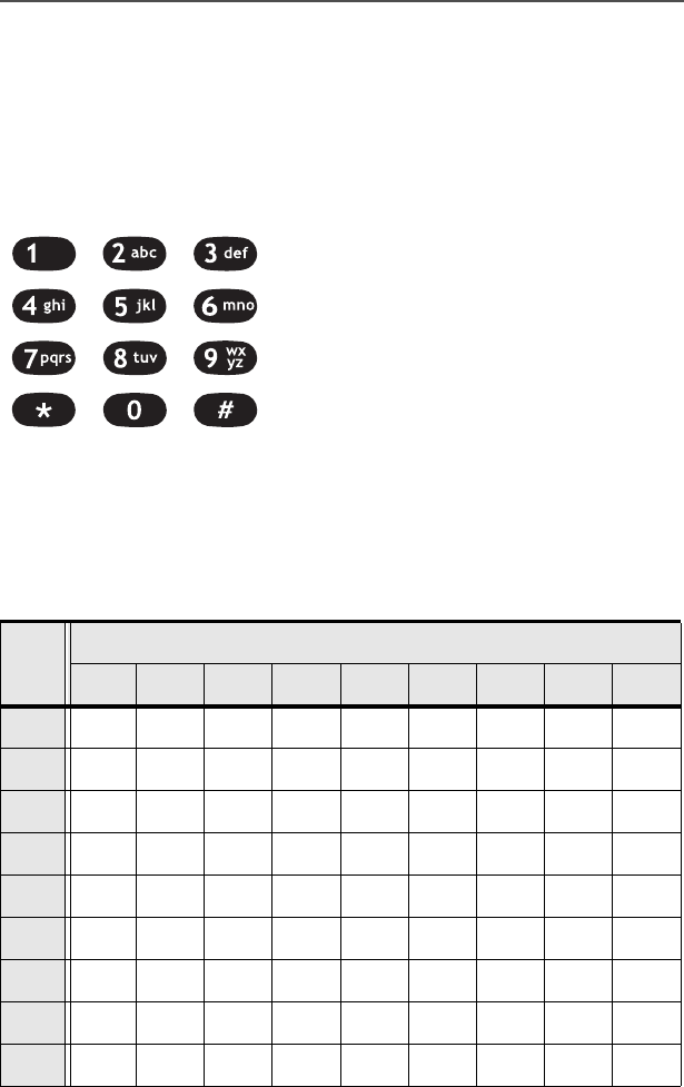
Keypad
The 3 x 4-key alphanumeric keypad
provides an interface to your radio’s
features.
The keypad functions in a manner
similar to a standard telephone keypad
when entering numeric digits.
When the keypad is used to edit a list,
each key can generate different
characters of the alphabet. Refer to
Table 6, below, for a complete list of
characters.
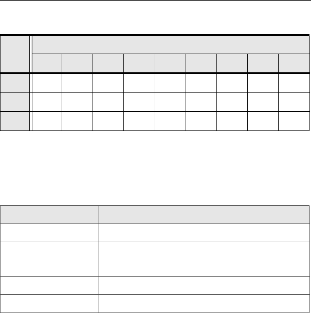
Table 6: Keypad Characters
Key
Number of times the key is pressed
123456789
00()<>
11&%
2ABC2abc
3DEF3de f
4GHI 4gh i
5JKL5 j k l
6MNO6mn o
7PQRS7pq r s
8TUV8 t u v
MAEPF-27194-A
10
General Radio Operation
LED Indicators
The LED on top of the radio indicates the radio’s operating status:
9WXYZ9wxyz
**/+-=
##. !?, ;
Table 7: LED Indicators
LED Indicator What it Means
Red Radio transmitting
Flashing red • Channel busy, or
• Low battery (while transmitting)
Double flashing red Receiving encrypted audio
Flashing green Receiving an individual call
Table 6: Keypad Characters (Continued)
Key
Number of times the key is pressed
123456789

ASTRO Digital XTS 5000 Model III 11
General Radio Operation
Alert Tones
An alert tone is a sound or group of sounds. Your radio uses alert
tones to inform you of your radio’s conditions. The following table lists
these tones and when they occur.
Table 8: Alert Tones
You Hear Tone Name Heard
Short,
Low-Pitched
Tone
Invalid
Key-Press
when wrong key is pressed
Radio Self-Test
Fail
when radio fails its power-up self
test
Reject when unauthorized request is
made
Time-Out Timer
Warning
four seconds before time out
Long, Low-
Pitched Tone
No ACK
Received
when radio fails to receive an
acknowledgment
Time-Out Timer
Timed Out
after time out
Talk Prohibit/
PTT Inhibit
(when PTT button is pressed)
transmissions are not allowed
Out-of-Range (when PTT button is pressed) the
radio is out of range of the system
Invalid Mode when radio is on an unprogrammed
channel
Individual Call
Warning Tone
when radio is in an individual call
for greater than 6 seconds without
any activity
A Group of
Low-Pitched
Tones
Busy when system is busy

12
General Radio Operation
Short,
Medium-
Pitched
Tone
Valid Key-
Press
when correct key is pressed
Radio Self-Test
Pass
when radio passes its power-up
self test
Clear Voice at beginning of a non-coded
communication
Priority
Channel
Received
when activity on a priority channel
is received
Emergency
Alarm Entry
when entering the emergency state
Central Echo when central controller has
received a request from a radio
Long,
Medium-
Pitched
Tone
Volume Set when volume is changed on a quiet
channel
Emergency Exit when exiting the emergency state
A Group of
Medium-
Pitched
Tones
Failsoft when the trunking system fails
Automatic Call
Back
when voice channel is available
from previous request
Talk Permit (when PTT button is pressed)
verifying system accepting
transmissions
Keyfail when encryption key has been lost
Console
Acknowledge
when status, emergency alarm, or
reprogram request ACK is received
Received
Individual Call
when Call Alert or Private Call is
received
Call Alert Sent when Call Alert is received by the
target radio
Short,
High-Pitched
Tone (Chirp)
Low-Battery
Chirp
when battery is below preset
threshold value
Table 8: Alert Tones (Continued)
You Hear Tone Name Heard

ASTRO Digital XTS 5000 Model III 13
General Radio Operation
Ringing
Fast Ringing when system is searching for target
of Private Call
Enhanced Call
Sent
when waiting for target of Private
Call to answer the call
Phone Call
Received
when a land-to-mobile phone call is
received
Gurgle Dynamic
Regrouping
(when the PTT button is pressed)
a dynamic ID has been received
Table 8: Alert Tones (Continued)
You Hear Tone Name Heard
14
General Radio Operation
Standard Accessories
Battery
Charging the Battery
The Motorola-approved battery shipped with your radio is uncharged.
Prior to using a new battery, charge it for a minimum of 16 hours to
ensure optimum capacity and performance.
For a list of Motorola-authorized batteries available for use with your
XTS 5000 radio, see “Batteries and Battery Accessories” on
page 105.
Note: When charging a battery attached to a radio, turn the radio off
to ensure a full charge.
Battery Charger
To charge the battery, place the battery, with or without the radio, in a
Motorola-approved charger. The charger’s LED indicates the
charging progress; see your charger’s user guide. For a list of
chargers, see “Chargers” on page 107.
Battery Charge Status
If programmed by a qualified radio technician, you can check your
battery’s charge status by holding down the pre-programmed Battery
Gauge button on the radio. Charge status is shown by the color of the
radio’s LED.
To avoid a possible explosion:
• DO NOT replace the battery in any area
labeled “hazardous atmosphere”.
• DO NOT discard batteries in a fire.
Battery Level LED Indicator
High Green
Sufficient Yellow
Low Flashing Red
Very low None
!
W A R N I N G
!
ASTRO Digital XTS 5000 Model III 15
General Radio Operation
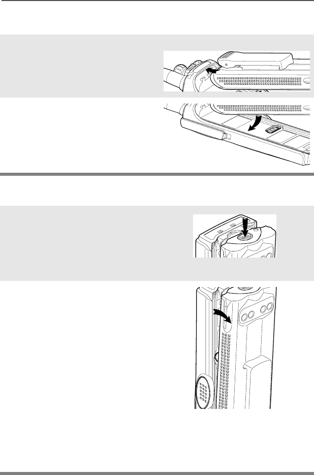
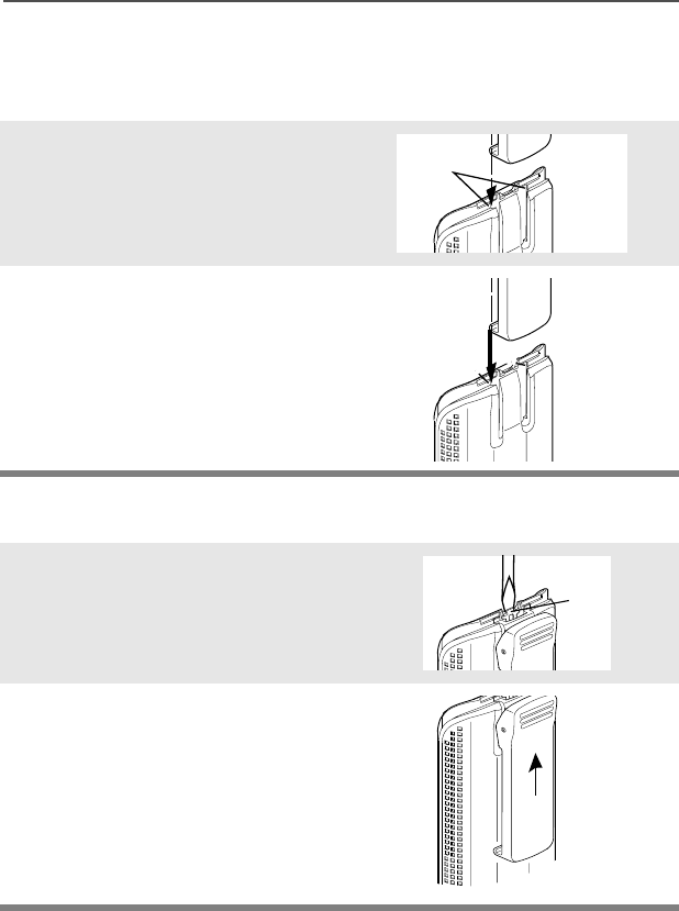
Attach the Battery
Remove the Battery
1With the radio turned off,
insert the top edge of the
battery into the radio’s frame
as shown.
2Rotate the battery toward the
radio and press down until the
battery clicks into place.
1With the radio turned off,
press the release button on
the bottom of the battery until
the battery releases from the
radio.
2Remove the battery from the
radio.
Note: If your radio is programmed with volatile-key retention,
encryption keys will be retained for approximately 30
seconds after battery removal. Consult a qualified radio
technician for details.
16
General Radio Operation
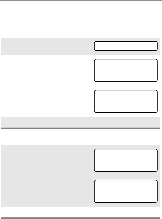
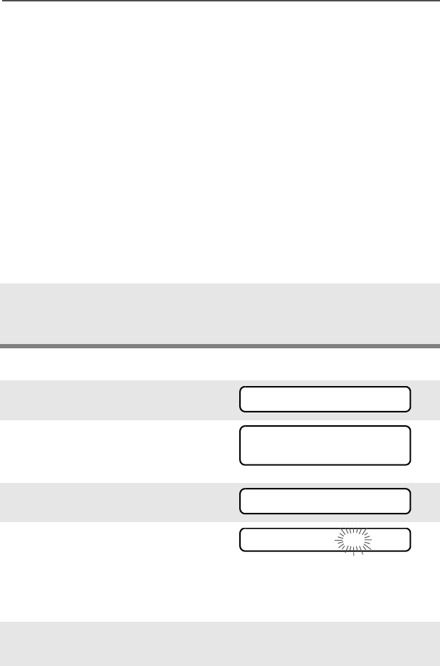
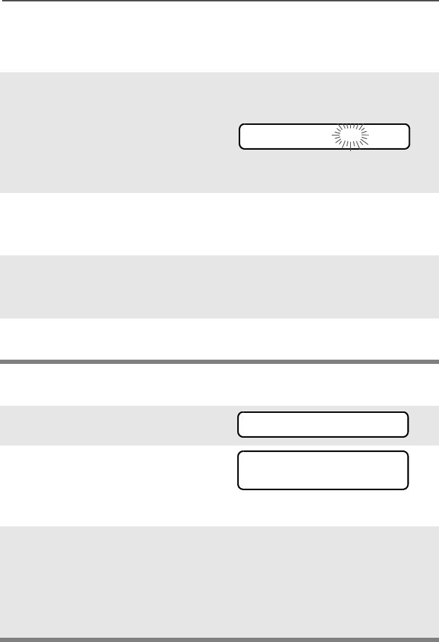
Smart Battery Status
This feature lets you view the status of your Smart Battery.
Use the Menu
Use the Preprogrammed Smart Battery Button
1Press U to find BATT.
2Press D, E, or F directly
below BATT.
Note: If a Smart Battery is not
powering your radio:
3Press h to exit.
1Press the Smart Battery
button.
Note: If a Smart Battery is not
powering your radio:
2Press h to exit.
BATT
CAPACITY 70%
INIT 10/01
EST CHGS 11
SMART BATT
DATA NOT
AVAILABLE.
CAPACITY 70%
INIT 10/01
EST CHGS 11
SMART BATT
DATA NOT
AVAILABLE.
ASTRO Digital XTS 5000 Model III 17
General Radio Operation
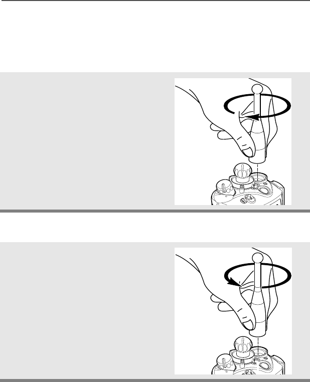
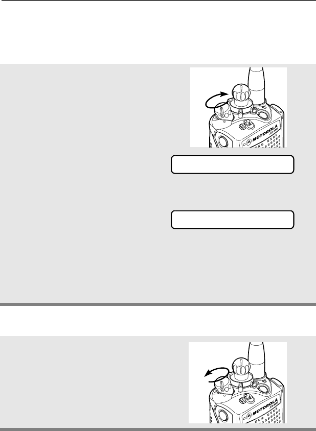
Antenna
For information regarding available antennas, see page 103.
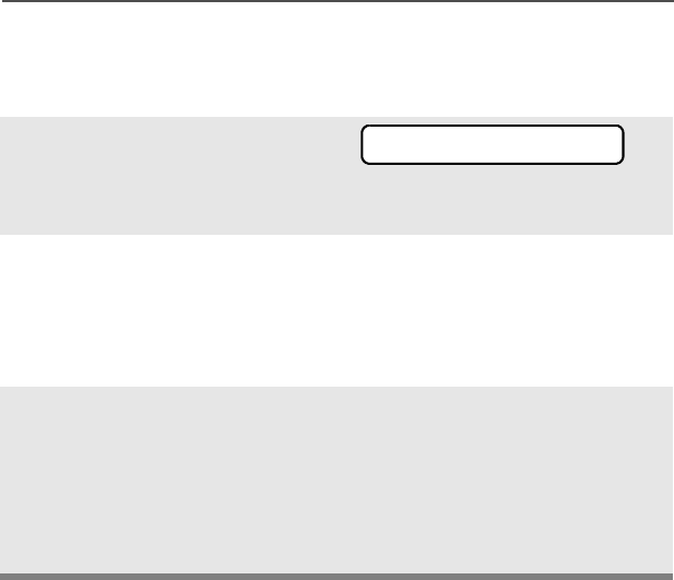
Attach the Antenna
Remove the Antenna
With the radio turned off, turn the
antenna clockwise to attach it to
the radio.
With the radio turned off, turn the
antenna counter-clockwise to
remove it from the radio.
18
General Radio Operation
Belt Clip
Attach the Belt Clip
Remove the Belt Clip
1Align the grooves of the belt
clip with those of the battery.
2Press the belt clip downward
until you clear a click.
1Use a flat-bladed object to
press the belt clip tab away
from the battery.
2Slide the belt clip upward to
remove it.
Slots
Battery
Battery
Grooves
Slots
Battery
Battery
Metal
Tab
ASTRO Digital XTS 5000 Model III 19
General Radio Operation
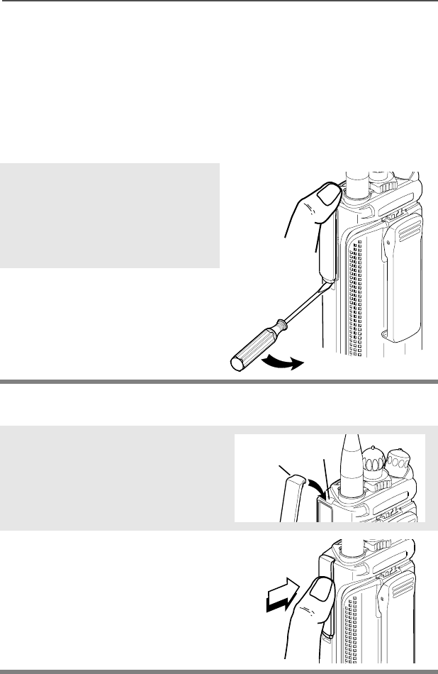
Universal Connector Cover
The universal connector is located on the antenna side of the radio. It
is used to connect accessories to the radio.
Note: To prevent damage to the connector, shield it with the
connector cover when not in use.
Remove the Universal Connector Cover
Attach the Universal Connector Cover
1Insert a flat-bladed
screwdriver into the area
between the bottom of the
cover and the slot below the
connector.
2Hold the top of the cover with
your thumb while you pry the
bottom of the cover away
from the radio with the
screwdriver.
1Insert the hooked end of the
cover into the slot above the
connector. Press downward
on the cover’s top to seat it in
the slot.
2Rub the ball of your thumb
from the top to the bottom of
the cover while applying
pressure towards the radio.
This should flex the cover and
snap it into place.
Top
Slot
Top
Hooked End
20
General Radio Operation
Radio On and Off
Turn the Radio On
Turn the Radio Off
Turn the On/Off/Volume Control
knob clockwise.
Note: If the power-up test is
successful, you briefly
see SELF TEST, then the
home display.
Note: If the power-up test is
unsuccessful, you see
ERROR XX/YY. (XX/YY is
an alphanumeric code.)
Turn off the radio, check the battery, and turn the radio on. If
the radio fails the power-up test again, record the ERROR XX/
YY code and contact a qualified radio technician.
Turn the On/Off/Volume Control
knob counterclockwise until it
clicks.
On
SELF TEST
ERROR XX/YY
Off
ASTRO Digital XTS 5000 Model III 21
General Radio Operation
Zones and Channels
A zone is a grouping of channels. A channel is a group of radio
characteristics, such as transmit/receive frequency pairs.
Before you use your radio to receive or send messages, you should
select the zone and channel.
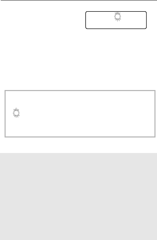
Select a Zone
Use the Menu
Use the Preprogrammed Zone Switch
1Press U to find ZONE.
2Press D, E, or F
directly below ZONE.
The current zone (in this
case, POL) flashes and the
channel name (DISP NW),
does not flash.
3Press U to find the zone
you want. For example,
FIRE.
4Press h to confirm the
displayed zone and channel.
OR
Press the PTT button to
transmit on the displayed
zone/channel.
1If a control on your radio has
been preprogrammed as the
Zone switch, move the Zone
switch to the position for the
zone you want.
ZONE
POL DISP NW
FIRE DISP NW
FIRE DISP NW
FIRE DISP NW
FIRE DISP NW

22
General Radio Operation
Select a Channel
Consult a qualified radio technician for the right choice between the
following methods:
Method 1: Use the Preprogrammed 16-Position Select Knob
Method 2: Use the Menu
Note: If the zone you selected
is unprogrammed, repeat
step 1.
2Press h to confirm the
displayed zone and channel.
After the zone you want is
displayed, turn the
16-Position Select knob to
the desired channel.
1Press U to find CHAN.
2Press D, E, or F
directly below CHAN.
The display shows the cur-
rent channel name (in this
case, DISP NW) flashing and
the zone (POL), not flashing.
3Press U to find the channel
name you want.
OR
Use the keypad to enter the
channel number.
FIRE DISP NWUNPROGRAMMED
FIRE DISP NW
Select
Channel
CHAN
POL DISP NW
POL DISP SE
ASTRO Digital XTS 5000 Model III 23
General Radio Operation
Note: If the channel you
selected is
unprogrammed, repeat
step 3.
4Press h to confirm the
displayed zone and channel.
OR
Press the PTT button to
transmit on the displayed
zone/channel.
UNPROGRAMMED
POL DISP SE
24
General Radio Operation
Receive / Transmit
Radio users who switch from analog to digital radios often assume
that the lack of static on a digital channel is an indication that the radio
is not working properly. This is not the case. Digital technology quiets
the transmission by removing the “noise” from the signal and allowing
only the clear voice or data information to be heard.
This section emphasizes the importance of knowing how to monitor a
channel for traffic before keying up to send a transmission.
Without Using the Volume Set and Monitor Buttons
Use the Preprogrammed Volume Set Button
1Turn the radio on and select
the desired zone and
channel.
2Listen for a transmission.
3Adjust the Volume Control
knob if necessary.
4Press and hold the PTT
button to transmit. The LED
lights RED while transmitting.
5Release the PTT button to
receive (listen).
1Turn the radio on and select
the desired zone and
channel.
2Press and hold the Volume
Set button to hear the volume
set tone.
A
djust
Level
ASTRO Digital XTS 5000 Model III 25
General Radio Operation
Use the Preprogrammed Monitor Button
3Adjust the Volume Control
knob if necessary.
4Release the Volume Set
button.
5Press and hold the PTT
button to transmit. The LED
lights RED while transmitting.
6Release the PTT button to
receive (listen).
1Turn the radio on and select
the desired zone and
channel.
2Press the Monitor button
and listen for activity. The
Carrier Squelch indicator is
displayed. (See the following
Conventional Mode
Operation.)
3Adjust the Volume Control
knob if necessary.
4Press and hold the PTT
button to transmit. The LED
lights RED while transmitting.
5Release the PTT button to
receive (listen).
A
djust
L
evel
C
A
djust
L
evel
26
General Radio Operation
Conventional Mode Operation
Your radio may be programmed to receive Private-Line® (PL) calls.
1Momentarily press the
Monitor button to listen for
activity. The Carrier Squelch
indicator is displayed.
2Press and hold the Monitor
button to set continuous
monitor operation. (The
duration of the button press is
programmable.)
3Press the Monitor button
again, or the PTT button, to
return to the original squelch
setting.
Note: If you try to transmit on a receive-only channel, you will hear
an invalid tone until you release the PTT button.
C
ASTRO Digital XTS 5000 Model III 27
Common Radio Features
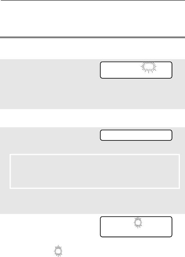
Selectable Power Level
This feature lets you select the power level at which your radio will
transmit. The radio will always turn on to the default setting. This
feature must be preprogrammed by a qualified radio technician.
•Select LOW for a shorter transmitting distance and to conserve
power.
•Select HIGH for a longer transmitting distance.
Use the Menu
1Press U to find PWR.
2Press D, E, or F
directly below PWR. The display
shows the current power level,
along with LOW and HIGH.OR
3Press D, E, or F directly
below the desired power level
(LOW or HIGH).
• The new transmit power
level is saved.
• The radio returns to the
home display.
Note: To exit without changing the setting, press h or the PTT
button.
PWR
HIGH POWER
LOW HIGH
LOW POWER
LOW HIGH

28
Common Radio Features
Use the Preprogrammed Transmit Power Level Switch
1Move the TX Power Level
switch to the Low Power
position. The power level is set
to Low.
2Move the TX Power Level
switch to the HIgh Power
position. The power level is set
to High.

ASTRO Digital XTS 5000 Model III 29
Common Radio Features
Radio Lock
This feature changes your radio to a more robust security system that
protects the use of the secure encryption keys. If this feature is
enabled in your radio by a qualified radio technician, when you turn
the radio on, you see RADIO LOCKED.
Unlock Your Radio
1Enter your numeric password.
Note:
•Secure-equipped radios — 6 to 8 characters.
•Clear radios — 0 to 8 characters.
If you make a mistake, press V to backspace.
2Press the preprogrammed
Select button after you enter
your password. If the password
is correct, the radio unlocks.
Note: If the password is incorrect,
the radio remains locked.
• If you enter three incorrect
passwords in a row, you see
DEADLOCK. Turn the radio off
and then on, and begin again at
step 1.
•Secure Radios Only — If you
enter a total of 17 consecutive
incorrect passwords (turning the
radio off and on does not reset
this number), the radio erases
all of its encryption keys and
shows “DEADLOCK.” See a
qualified radio technician.
--------
RADIO LOCKED
DEADLOCK
DEADLOCK
30
Common Radio Features
Change Your Password
1Press U to find PSWD.
2Press D, E, or F directly
below PSWD.
3Enter the old password.
4Press D, E, or F directly
below SEL.
5Enter the new password.
6Press D, E, or F directly
below SEL.
7Re-enter the new password.
8Press D, E, or F directly
below SEL. The password is
updated.
Note: If the two passwords do not
match, repeat steps 5
through 8.
Note: If you enter three incorrect old passwords, the radio exits
the password feature. You cannot access this feature again
until you turn the radio off and on.
PSWD
OLD PASSWORD
--------
SEL
NEW PASSWORD
SEL
--------
SEL
-
SEL
--------
SEL
NEW PASSWORD
ASTRO Digital XTS 5000 Model III 31
Common Radio Features
Enable or Disable the Radio Lock Feature
(Secure Radios Only)
This feature (programmable by a qualified radio technician) allows
you to enable or disable the radio lock feature.
1Press U to find LOGF.
2Press D, E, or F directly
below LOGF. You see the current
state. OR
3To enable the radio lock feature,
press D, E, or F directly
below ENAB.
OR
To disable the radio lock fea-
ture, press D, E, or F
directly below DSAB.
LOGF
PSWD ENABLD
ENAB DSAB
PSWD DISBLD
ENAB DSAB
32
Common Radio Features
Mute or Unmute Keypad Tones
You can turn the keypad tones on or off.
Use the Menu
Use the Preprogrammed Keypad Mute Button
1Press U to find MUTE.
2Press D, E, or F
directly below MUTE. The
current state is shown.
OR
3Press D, E, or F
directly below OFF or ON.
Note: Press h or the PTT button to exit without changing the
setting.
Press the Keypad Mute
button to turn the tones off or
on.
MUTE
TONES OFF
OFF ON
TONES ON
OFF ON

ASTRO Digital XTS 5000 Model III 33
Common Radio Features
Conventional Squelch Operation
Analog Options
Tone Private Line (PL), Digital Private-Line (DPL), and carrier squelch
can be available (preprogrammed) per channel.
Digital Options
One or more of the following options may be programmed in your
radio. Consult your service technician for more information.
When in This condition occurs
Carrier squelch (C) You hear all traffic on a channel.
PL or DPL The radio responds only to your
messages.
This option Will allow you to hear
Digital Carrier-Operated
Squelch (COS)
any digital traffic.
Normal Squelch any digital traffic having the correct
network access code.
Selective Switch any digital traffic having the correct
network access code and correct
talkgroup.

34
Common Radio Features
PL Defeat
With this feature, you can override any coded squelch (DPL or PL)
that might be preprogrammed to a channel.
Place the preprogrammed
PL Defeat switch in the PL
Defeat position. You can
now hear any activity on the
channel. The radio is muted
if no activity is present.
When this feature is active,
the Carrier Squelch status
indicator (C) will be
displayed.
C

ASTRO Digital XTS 5000 Model III 35
Common Radio Features
Time-out Timer
The time-out timer turns off your radio’s transmitter. The timer is set
for 60 seconds at the factory, but it can be programmed from 0 to 7.75
minutes (465 seconds) by a qualified radio technician.
1Hold down the PTT button
longer than the programmed
time. You will hear a short,
low-pitched warning tone,
the transmission will cut-off,
and the LED will go out until
you release the PTT.
• Short warning tone
• Transmission is cut-off
• LED goes out
2Release the PTT button. • LED re-lights
•Timer resets
3Press the PTT to re-transmit.
The time-out timer restarts.
• Timer restarts
•LED is red

36
Common Radio Features
Emergency
If the top (orange) button is programmed to send an emergency
signal, then this signal overrides any other communication over the
selected channel.
Your radio can be programmed for the following:
• Emergency Alarm
• Emergency Call
• Emergency Alarm with Emergency Call
• Silent Emergency Alarm
Consult a qualified radio technician for emergency programming of
your radio.
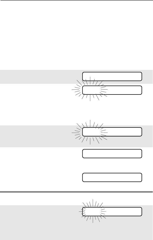
Send an Emergency Alarm
An emergency alarm will send a data transmission to the dispatcher,
identifying the radio sending the emergency.
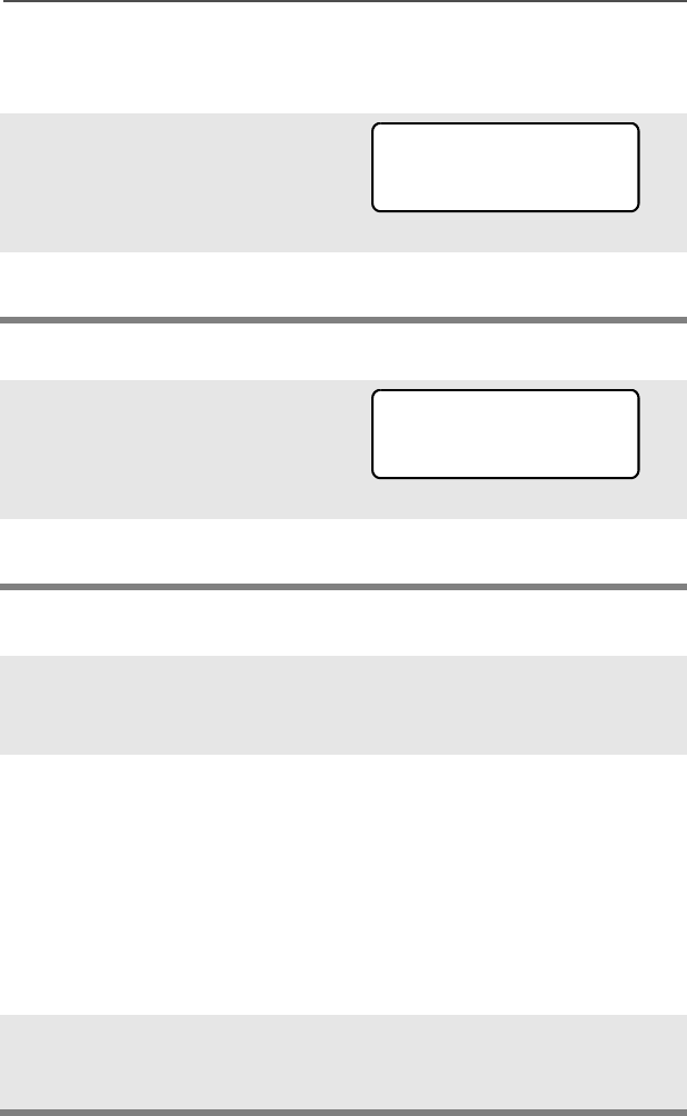
1With your radio turned on,
press the Emergency
button. The current zone/
channel is displayed
alternately with EMERGENCY,
the red LED lights, and a
short, medium-pitched tone
sounds.
If the selected channel does
not support emergency, the
display shows
NO EMERGENCY. Select a
channel that does show
EMERGENCY.
•Red LED
•Short tone
Note: To exit emergency at any time, press and hold the
Emergency button for about a second.
EMERGENCY
NO EMERGENCY

ASTRO Digital XTS 5000 Model III 37
Common Radio Features
Send an Emergency Call
2When you receive the
dispatcher’s
acknowledgment, you see
ACK RECEIVED, four tones
sound, the alarm ends, and
the radio exits the emergency
mode.
If no acknowledgement is
received, you see NO
ACKNOWLDG, the alarm ends,
and the radio exits the emer-
gency mode.
• Four tones
• Alarm ends
• Radio exits emergency
• Alarm ends
• Radio exits emergency
Note: For Emergency Alarm with Emergency Call: The radio
enters the Emergency Call state either after it receives the
dispatcher’s acknowledgment, or if you press the PTT button
while in Emergency Alarm. Go to step 2 of “Send an
Emergency Call”, below.
This type of dispatch gives your radio priority access on a channel.
The radio operates in the normal dispatch manner while in
Emergency Call, except, if enabled, it will return to one of the
following:
• Tactical/Non-Revert — You talk on the channel you selected
before you entered the emergency state.
• Non-Tactical/Revert — You talk on a preprogrammed emergency
channel. The emergency alarm is sent on this same channel.
1With your radio turned on,
press the Emergency
button.The current zone/
channel is displayed
alternately with EMERGENCY,
and a short, medium-pitched
tone sounds.
• Short tone
ACK RECEIVED
NO ACKNOWLDG
EMERGENCY

38
Common Radio Features
Send a Silent Emergency Alarm
Note: To exit emergency at any time, press and hold the
Emergency button for about a second.
2Press and hold the PTT
button and announce your
emergency into the
microphone.
3Release the PTT button to
end the transmission and wait
for a response from the
dispatcher.
4Press and hold the
Emergency button for about
a second to exit emergency.
1With your radio turned on,
press the Emergency
button. The display does not
change, the LED does not
light, and you hear no tones.
• Display does not change
• LED does not light
• No tones
Note: To exit emergency at any time, press and hold the
Emergency button for about a second.
2The silent emergency state
continues until you:
Press and hold the
Emergency button for about
a second to exit the
emergency state.
OR
Press and release the PTT
button to exit silent
emergency and enter regular
dispatch or emergency call.
• Press and hold Emergency
button
OR
• Press and release the PTT
button

ASTRO Digital XTS 5000 Model III 39
Common Radio Features
Note: For ALL Emergency signals, when changing channels:
• If the new channel is also programmed for Emergency, you can
change channels while in Emergency operation. The
emergency alarm or call continues on the new channel.
• If the new channel is NOT programmed for Emergency, you
see NO EMERGENCY, and hear an invalid tone until you exit
the Emergency state or change to a channel programmed for
emergency.
Emergency Keep-Alive
If the radio is in the Emergency state, with Emergency Keep-Alive
enabled, you cannot turn off the radio by using the On/Off Control
knob.
With Keep-Alive, the radio will only exit the Emergency state using
one of the ways mentioned in the previous sections (Emergency
Alarm, Silent Emergency Alarm, or Emergency Call).
40
Common Radio Features
Lists
You can use lists to store frequently used numbers and associate
them with names. There are four list types:
•Call
• Page
• Phone
• Scan
View a List
Scan List Empty
1Press U to find VIEW.
2Press D, E, or F
directly below VIEW.
3Press V or U to see the
names of available lists.
4Press D, E, or F
directly below the name of the
list you wish to view. You see
the first list member.
p indicates the view mode.
5Press V or U to view
other list members.
6Press h to exit.
If you wish to view a scan list and
the list has no entries, you see
EMPTY LIST.
To end this display, turn scan off
or edit the list.
VIEW
CALL
PAGE PHON
FIRE CHIEF p
701234
EMPTY LIST
ASTRO Digital XTS 5000 Model III 41
Common Radio Features
Edit a Call, Page, or Phone List Number
Use the Menu
1Press U to find PROG.
2Press D, E, or F
directly below PROG. You see
the lists that can be changed.
3Press D, E, or F
directly below the name of the
list you wish to change. You
see the first list member. p
(flashing) indicates the
programming mode.
4Press V or U to select
the list member to be
changed.
OR
You can use the keypad to
enter the corresponding
location number of the name
in the list.
5Press D, E, or F
directly below NUM. The
blinking cursor shows the
location of the number to be
added.
6Press V to erase digits. (If
you erase the entire number
and then press V or U,
you exit editing without saving
your changes.) Press a
keypad button to add a digit
(see “Keypad” on page 9).
PROG
CALL
PAGE PHON
FIRE CHIEF p
701234
NUM NAME
SECURITY p
704321
NUM NAME
SECURITY p
70432_
SAVE
SECURITY p
704321_
SAVE
42
Common Radio Features
Edit a Call, Page, or Phone List Name
Use the Menu
7Press D, E, or F
directly below SAVE to save
your change. Return to step 4
to make more changes.
OR
Press h to return to the home
display.
1Press U to find PROG.
2Press D, E, or F
directly below PROG. You see
the lists that can be changed.
3Press D, E, or F
directly below the name of the
list you wish to change. You
see the first list member. p
(flashing) indicates the
programming mode.
4Press V or U to select
the list member to be
changed.
OR
You can use the keypad to
enter the corresponding
location number of the name
in the list.
PROG
CALL
PAGE PHON
FIRE CHIEF p
701234
NUM NAME
SECURITY p
704321
NUM NAME
ASTRO Digital XTS 5000 Model III 43
Common Radio Features
Edit a Scan List
This feature lets you change scan list members and priorities.
Use the Menu
5Press D, E, or F
directly below NAME. The
blinking cursor shows the
location of the character to be
added.
6Press V to erase
characters. (If you erase the
entire name and press V or
U, you exit editing without
saving your changes.) Press
a keypad button to add a
character (see “Keypad” on
page 9).
7Press D, E, or F
directly below SAVE to save
your change. Return to step 4
to make more changes.
OR
Press h to return to the home
display.
1Press U to find PROG.
2Press D, E, or F
directly below PROG. You see
the lists that can be changed.
3Press U to find SCAN.
GUARD_ p
704444
SAVE
_ p
704444
SAVE
PROG
CALL
PAGE PHON
SCAN
44
Common Radio Features
4Press D, E, or F
directly below SCAN. You see
the first list member.
p (flashing) indicates the
programming mode.
5Press V or U to find the
member you want to change.
6Press D, E, or F
directly below SEL or DEL or
RCL.
SEL = add and/or change the priority of the currently displayed
channel in the scan list.
DEL = delete the currently displayed channel from the scan list.
RCL = view the next member of the scan list.
Note: The maximum number of members for a trunking priority
monitor scan list is 15; for a conventional scan list, 15; and
for a talkgroup scan list, 10.
7To change the priority of the
currently displayed channel,
press D, E, or F
below SEL additional times to
see T or S or S or no icon.
T = this channel is in the scan list as a non-priority channel.
S = this channel is in the scan list as the priority 2 channel.
S (dot flashing) = this channel is in the scan list as the priority 1
channel. You will hear all traffic on the priority 1 channel,
regardless of traffic on non-priority channels.
no icon = this channel is deleted from the scan list.
Note: You cannot delete a priority channel from a scan list. In a
talkgroup scan list, priority cannot be assigned.
FIRE DISP NW p
SEL DEL RCL
SEL DEL RCL
T or S or S or no icon
ASTRO Digital XTS 5000 Model III 45
Common Radio Features
Use the Menu and the Preprogrammed Select (Top Side) Button
8Press V or U to select
more channels to be added or
deleted.
OR
Use the keypad to go directly
to additional channels to be
added or deleted.
OR
Use the 16-Position Select
knob to select additional
channels to be added or
deleted.
9Press h to exit scan list
programming and return to
the home display.
1Press U to find PROG.
2Press D, E, or F
directly below PROG. You see
the lists that can be changed.
3Press U to find SCAN.
4Press D, E, or F
directly below SCAN. You see
the first list member.
p (flashing) indicates the
programming mode.
5Press V or U to find the
member you want to change.
PROG
CALL
PAGE PHON
SCAN
FIRE DISP NW p
46
Common Radio Features
6Press the Select button once
to add the currently displayed
channel to the scan list.
AND/OR
Press the Select button one
or more times to change the
scan list status symbol of the
currently displayed channel.
Note: The maximum number of members for a trunking priority
monitor scan list is 15; for a conventional scan list, 15; and
for a talkgroup scan list, 10.
T = this channel is in the scan list as a non-priority channel.
S = this channel is in the scan list as the priority 2 channel.
S (dot flashing) = this channel is in the scan list as the priority 1
channel. You will hear all traffic on the priority 1 channel,
regardless of traffic on non-priority channels.
no icon = this channel is deleted from the scan list.
Note: You cannot delete a priority channel from a scan list. In a
talkgroup scan list, priority cannot be assigned.
7Press V or U to select
more scan list members
whose scan status you want
to change.
OR
Use the keypad to go directly
to that scan list member.
OR
Use the 16-Position Select
knob to select another scan
list member.
T or S or S or no icon
ASTRO Digital XTS 5000 Model III 47
Common Radio Features
Use the Preprogrammed Scan List Programming Switch and the
Menu
8Press h to exit scan list
programming and return to
the home display.
1Move the Scan List
Programming switch to the
Programming position. You
see the first list member. p
(flashing) indicates the
programming mode.
2Press V or U to find the
member you want to change.
3Press D, E, or F
directly below SEL or DEL or
RCL.
SEL = add and/or change the priority of the currently displayed
channel in the scan list.
DEL = delete the currently displayed channel from the scan list.
RCL = view the next member of the scan list.
Note: The maximum number of members for a trunking priority
monitor scan list is 15; for a conventional scan list, 15; and
for a talkgroup scan list, 10.
4To change the priority of the
currently displayed channel,
press D, E, or F
below SEL additional times to
see T or S or S or no icon.
FIRE DISP NW p
SEL DEL RCL
SEL DEL RCL
T or S or S or no icon
48
Common Radio Features
Change the Scan List Status Only
T = this channel is in the scan list as a non-priority channel.
S = this channel is in the scan list as the priority 2 channel.
S (dot flashing) = this channel is in the scan list as the priority 1
channel. You will hear all traffic on the priority 1 channel,
regardless of traffic on non-priority channels.
no icon = this channel is deleted from the scan list.
Note: You cannot delete a priority channel from a scan list. In a
talkgroup scan list, priority cannot be assigned.
5Press V or U to select
more channels to be added or
deleted.
OR
Use the keypad to go directly
to additional channels to be
added or deleted.
OR
Use the 16-Position Select
knob to select additional
channels to be added or
deleted.
6Move the Scan List
Programming switch out of
the Programming position.
1Move the Scan List
Programming switch to the
Programming position. You
see the first list member.
p (flashing) indicates the
programming mode.
FIRE DISP NW p

ASTRO Digital XTS 5000 Model III 49
Common Radio Features
2Press V or U to find the
member you want to change.
3Press the Select button once
to add the currently displayed
channel to the scan list.
AND/OR
Press the Select button one
or more times to change the
scan list status symbol of the
currently displayed channel.
Note: The maximum number of members for a trunking priority
monitor scan list is 15; for a conventional scan list, 15; and
for a talkgroup scan list, 10.
T = this channel is in the scan list as a non-priority channel.
S = this channel is in the scan list as the priority 2 channel.
S (dot flashing) = this channel is in the scan list as the priority 1
channel. You will hear all traffic on the priority 1 channel,
regardless of traffic on non-priority channels.
no icon = this channel is deleted from the scan list.
Note: You cannot delete a priority channel from a scan list. In a
talkgroup scan list, priority cannot be assigned.
4Press V or U to select
more list members whose
scan status you want to
change.
OR
You can use the keypad to go
directly to that scan list mem-
ber.
OR
T or S or S or no icon

50
Common Radio Features
You can use the 16-Position
Select knob to select another
scan list member.
5Move the Scan List
Programming switch out of
the Programming position.
ASTRO Digital XTS 5000 Model III 51
Common Radio Features
Scan
The scan feature allows you to monitor traffic on different channels by
scanning a preprogrammed list of channels. Your radio can have up
to 32 different scan lists. These lists must be preprogrammed by a
qualified radio technician.
• To view your radio’s scan lists, see “View a List” on page 40.
• To change your radio’s scan lists, see “Edit a Scan List” on
page 43.
Turn Scan On or Off
Use the Menu
Use the Preprogrammed Scan On/Off Switch
1Press U to find SCAN.
2Press D, E, or F
directly below SCAN. You see
the current scan state.
The scan status symbol is
displayed when scan is on.
OR
3Press D, E, or F
directly below ON or OFF.
OR
You can press h or the PTT
button to exit scan and return
to the home display without
changing the scan state.
Place the Scan switch in the
Scan On or Scan Off posi-
tion. The scan status symbol
is displayed when scan is on.
SCAN
SCAN ON T
ON OFF
SCAN OFF
ON OFF
SCAN
T

52
Common Radio Features
Delete a Nuisance Channel
When the radio scans to a channel that you do not wish to hear
(nuisance channel), you can temporarily delete the channel from the
scan list.
1When the radio is locked
onto the channel to be
deleted, press the
preprogrammed Nuisance
Delete button.
Repeat this step to delete
more channels.
Note: You cannot delete priority
channels or the
designated transmit
channel.
2The radio continues scanning
the remaining channels in the
list. To resume scanning the
deleted channel, change
channels or turn scan off and
then back on again.

ASTRO Digital XTS 5000 Model III 53
Common Radio Features
Conventional Scan Only
Make a Dynamic Priority Change
While the radio is scanning, the dynamic priority change feature lets
you temporarily change any channel in a scan list (except the priority-
one channel) to the priority-two channel. The replaced priority-two
channel becomes a non-priority channel. This change remains in
effect until scan is turned off, then scanning reverts back to the
preprogrammed state.
1When the radio is locked
onto the channel to be
designated as priority-two,
press the preprogrammed
Dynamic Priority button.
Note: The priority-one
channel cannot be
changed to priority-
two.
2The radio continues scanning
the remaining channels in the
list. To resume scanning the
preprogrammed priority-two
channel, you must leave and
re-enter scan operation.

54
Common Radio Features
Telephone Calls (Trunking Only)
Use your radio to make calls similar to standard phone calls. A
landline phone can be used to call a radio, or a radio can be used to
call a landline phone.
Quick Access (One-Touch)
If your radio is preprogrammed for Quick Access (One-Touch) Phone
Call, you can make a call to one preprogrammed phone number
without having to select the feature or a phone number.
1Press the Quick Access
Phone button to dial the
phone number.
2If your call is answered, press
the PTT button to talk;
release the PTT to listen.
OR
If your call is not answered,
go to “Phone Call Display
and Alert Prompts” on
page 57.
3When your call is completed,
press h to hang up. The radio
returns to the home display.
ASTRO Digital XTS 5000 Model III 55
Common Radio Features
Answer a Phone Call
Use the preprogrammed Call Response button to answer a call.
Initiate a Phone Call
1When a phone call is
received, you hear a
telephone-type ringing, the
LED flashes GREEN, the call
received symbol (m) flashes,
and PHONE CALL is displayed.
• Telephone-type ringing
• Flashing GREEN LED
2Press the Call Response
button within 20 seconds after
the call indicators begin.
3Press and hold the PTT
button to talk; release it to
listen.
4Press h to hang up and return
to the home display.
1Press U to find PHON.
2Press D, E, or F
directly below PHON. You see
the last transmitted phone
number.
3Go to “Select a Phone
Number” on page 56.
OR
Go to “Make a Phone Call”
on page 56.
•Use the Menu
• Use the Keypad
PHONE CALL m
PHON
555-1234
LIST
56
Common Radio Features
Select a Phone Number
Use the Menu
Use the Keypad
Make a Phone Call
1Press U to find the phone
number you want.
Note: Press LNUM to go to the
last number dialed.
2Go to “Make a Phone Call”,
below.
1Use the keypad to enter the
phone number you want.
Note: Press LNUM to go to the
last number dialed.
2Go to “Make a Phone Call”,
below.
1Press and release the PTT
button to dial the phone
number.
2If your call is answered, press
the PTT button to talk;
release the PTT to listen.
OR
If your call is not answered,
go to “Phone Call Display
and Alert Prompts” on
page 57.
3When your call is completed,
press h to hang up. The radio
returns to the home display.
POLICE
555-8523
LNUM
POLICE
555-8523
LNUM
ASTRO Digital XTS 5000 Model III 57
Common Radio Features
Table 9: Phone Call Display and Alert Prompts
When you press the PTT button
and the phone system is not
available, you hear a long tone.
Press h to hang up. The radio
returns to the home display.
•A long tone
When a channel is not available,
you hear a busy tone.
The radio automatically connects
when a channel opens.
• A busy tone
When the phone system is busy,
you hear a long tone.
Press h to exit the phone mode
and try your call later.
•A long tone
The call is not acknowledged.
Press h to hang up. The radio
returns to the home display.
Notes: • A high-pitched tone, generated when you release the PTT
button, indicates to the landline party that he or she may
begin talking.
• You have the option of sending additional digits (overdial),
such as an extension number, or credit card or PIN
numbers, to the phone system. If the radio is programmed
for live overdial, every digit entered after the call is
connected is sent to the phone system.
• If the radio is programmed for buffered overdial, the digits
pressed are entered into memory and then sent when the
PTT button is pressed. Press the PTT to send either digits
or voice, but not both at the same time.
NO PHONE
PHONE BUSY
PHONE BUSY
NO ACKNOWLDG
58
Common Radio Features
Private Calls (Trunking Only)
These one-to-one calls between two radios are not heard by others in
the current talkgroup. The calling radio automatically verifies that the
receiving radio is active on the system and can display the caller’s ID.
Quick Access (One-Touch)
If your radio is preprogrammed for Quick Access (One-Touch) Private
Call, you can make a call to one preprogrammed ID number without
having to select the feature or an ID number.
1Press the Quick Access
Private Call button to start
the Private Call.
The called ID is momentarily
displayed, then you see
PLEASE WAIT.
2When you are connected, you
see the called ID. Press and
hold the PTT button to talk;
release the PTT to listen.
OR
If no acknowledgment is
received, you see NO
ACKNOWLDG.
OR
If the target radio does not
respond before the time out,
you see NO ANSWER.
3Press h to hang up and return
to the home display.
FIRE CHIEF
ID: 701234
PLEASE WAIT
FIRE CHIEF
ID: 701234
NO ACKNOWLDG
NO ANSWER
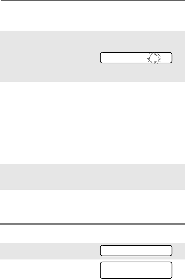
ASTRO Digital XTS 5000 Model III 59
Common Radio Features
Answer a Private Call
Use the preprogrammed Call Response button to answer a call.
Initiate a Private Call
1When a Private Call is
received, you hear two alert
tones, the LED flashes
GREEN, the call received
symbol (m) flashes, and CALL
RECEIVD is displayed.
•Two tones
• Flashing GREEN LED
2Press the Call Response
button within 20 seconds.
If the caller’s name is in the
call list, it will be displayed
during the call.
OR
If the caller’s name is not in
the call list, the caller’s ID
number is displayed.
3Press and hold the PTT
button to talk; release it to
listen.
4Press h or the Call
Response button to hang up
and return to the home
display.
1Press U to find CALL.
2Press D, E, or F
directly below CALL. You see
the last transmitted or
received ID number.
CALL RECEIVD m
CALL
ID: 702345
LIST
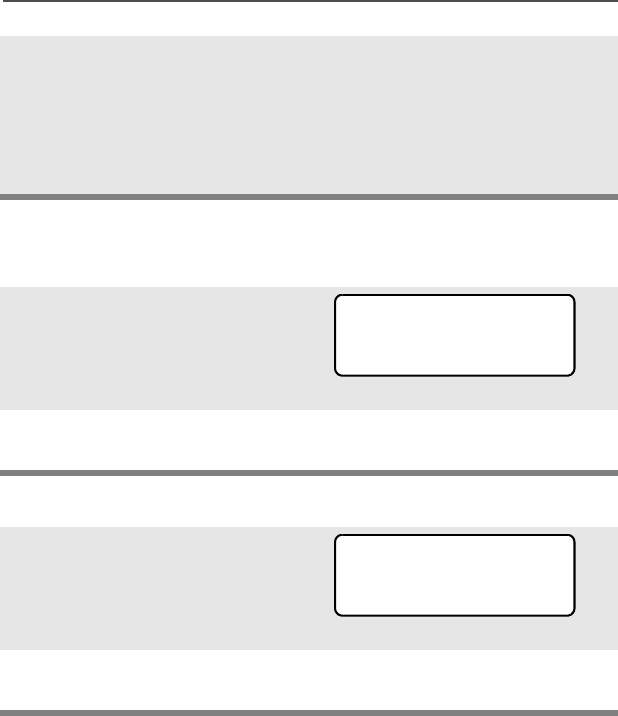
60
Common Radio Features
Select an ID Number
Use the Menu
Use the Keypad
3Go to “Select an ID Number”,
below.
OR
Go to “Make a Private Call”
on page 61.
• Use the Menu
• Use the Keypad
1Press U to find the ID
number you want.
Note: Press LNUM to go to the
last number dialed.
2Go to “Make a Private Call”
on page 61.
1Use the keypad to enter the
ID number you want.
Note: Press LNUM to go to the
last number dialed.
2Go to “Make a Private Call”
on page 61.
FIRE CHIEF
ID: 701234
LNUM
FIRE CHIEF
ID: 701234
LNUM
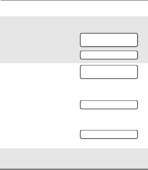
ASTRO Digital XTS 5000 Model III 61
Common Radio Features
Make a Private Call
1Press the PTT button to start
the Private Call.
The called ID is momentarily
displayed, then you see
PLEASE WAIT.
2When you are connected, you
see the called ID. Press and
hold the PTT button to talk;
release the PTT to listen.
OR
If no acknowledgment is
received, you see NO
ACKNOWLDG.
OR
If the target radio does not
respond before the time out,
you see NO ANSWER.
3When your call is completed,
press h to hang up. The radio
returns to the home display.
FIRE CHIEF
ID: 701234
PLEASE WAIT
FIRE CHIEF
ID: 701234
NO ACKNOWLDG
NO ANSWER
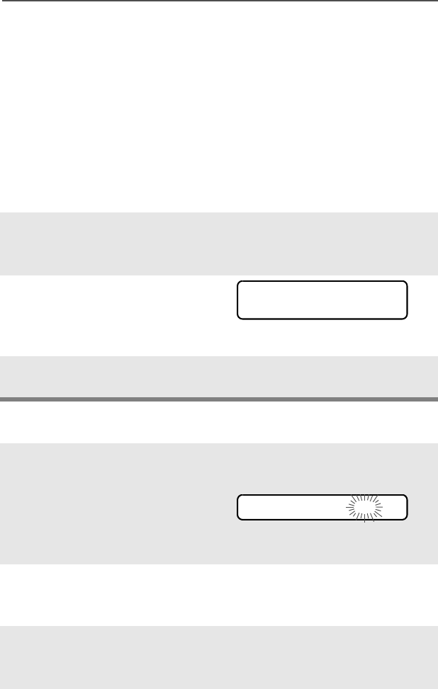
62
Common Radio Features
Selective Calls (ASTRO Conventional Only)
A Selective Call is used to call a select individual. It is intended to
provide privacy and to eliminate the annoyance of having to listen to
conversations that are of no interest to you.
Quick Access (One-Touch)
If your radio is preprogrammed for Quick Access (One-Touch)
Selective Call, you can make a call to one preprogrammed ID number
without having to select the feature or an ID number.
Answer a Selective Call
1Press the Quick Access
Selective Call button to start
the Selective Call.
2When you are connected, you
see the called ID. Press and
hold the PTT button to talk;
release the PTT to listen.
3Press h to hang up and return
to the home display.
1When a Selective Call is
received, you hear two alert
tones, the LED flashes
GREEN, the call received
symbol (m) flashes, and CALL
RECEIVD is displayed.
•Two tones
• Flashing GREEN LED
2The display will remain active
for two seconds, and then
the speaker will unmute.
3Press and hold the PTT
button to talk; release it to
listen.
FIRE CHIEF
ID: 701234
CALL RECEIVD m
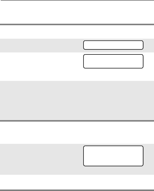
ASTRO Digital XTS 5000 Model III 63
Common Radio Features
Initiate a Selective Call
Select an ID Number
Use the Menu
4Press h to hang up and return
to the home display.
1Press U to find CALL.
2Press D, E, or F
directly below CALL. You see
the last transmitted or
received ID number.
3Go to “Select an ID Number”,
below.
OR
Go to “Make a Selective Call”
on page 64.
•Use the Menu
• Use the Keypad
1Press U to find the ID
number you want.
Note: Press LNUM to go to the
last number dialed.
2Go to “Make a Selective Call”
on page 64.
CALL
ID: 702345
LIST
FIRE CHIEF
ID: 701234
LNUM
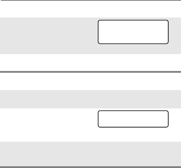
64
Common Radio Features
Use the Keypad
Make a Selective Call
1Use the keypad to enter the
ID number you want.
Note: Press LNUM to go to the
last number dialed.
2Go to “Make a Selective
Call”, below.
1Press the PTT button to start
the Selective Call.
2When you are connected, you
see the called ID. Press and
hold the PTT button to talk;
release the PTT to listen.
3When your call is completed,
press h to hang up. The radio
returns to the home display.
FIRE CHIEF
ID: 701234
LNUM
FIRE CHIEF
ID: 701234

ASTRO Digital XTS 5000 Model III 65
Common Radio Features
Call Alert Paging
Call Alert allows your radio to work like a pager. Even if other users
are away from their radios, or if they are unable to hear their radios,
you can still send them a Call Alert page. You can also verify if a radio
is active on the system.
In conventional operation, you can send either an individual Call Alert
page or a group Call Alert page. ID numbers for individuals are
preceded by ID: and for groups by GR:.
Quick Access (One-Touch)
If your radio is preprogrammed for Quick Access (One-Touch) Call
Alert Paging, you can send a page to one preprogrammed ID number
without having to select the feature or an ID number.
1Press the Quick Access
Call Alert button to send the
Call Alert. You see PLEASE
WAIT.
2When you are connected, you
see the home display. Press
and hold the PTT
button to talk; release the
PTT to listen.
OR
If an individual Call Alert
page is not acknowledged,
you see NO ACKNOWLDG.
If a group Call Alert page is
not acknowledged, you do
not see NO ACKNOWLDG. The
radio will merely exit Call
Alert and return to normal
operation.
PLEASE WAIT
NO ACKNOWLDG
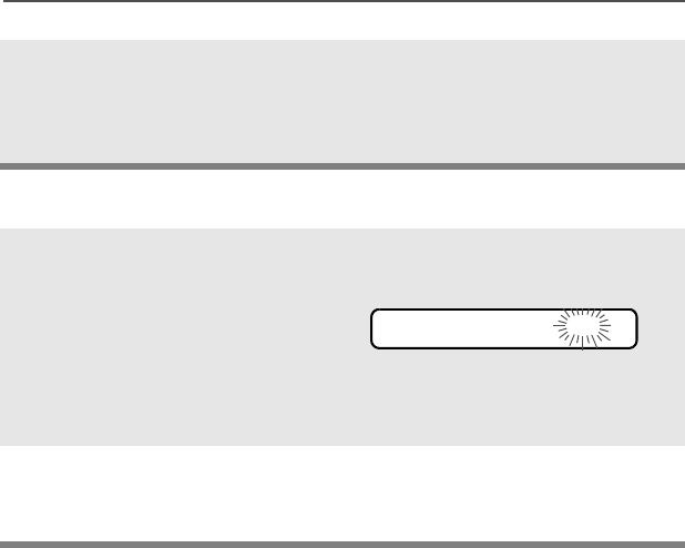
66
Common Radio Features
Answer a Call Alert Page
3Press h or the Call
Response button to hang up
and return to the home
display.
1When a Call Alert page is
received, you hear four
repeating alert tones, the
LED flashes GREEN, the call
received symbol (m) flashes,
and PAGE RECEIVD is
displayed.
• Four repeating alert tones
• Flashing GREEN LED
=
2Press and hold the PTT
button to talk; release it to
listen.
PAGE RECEIVD m
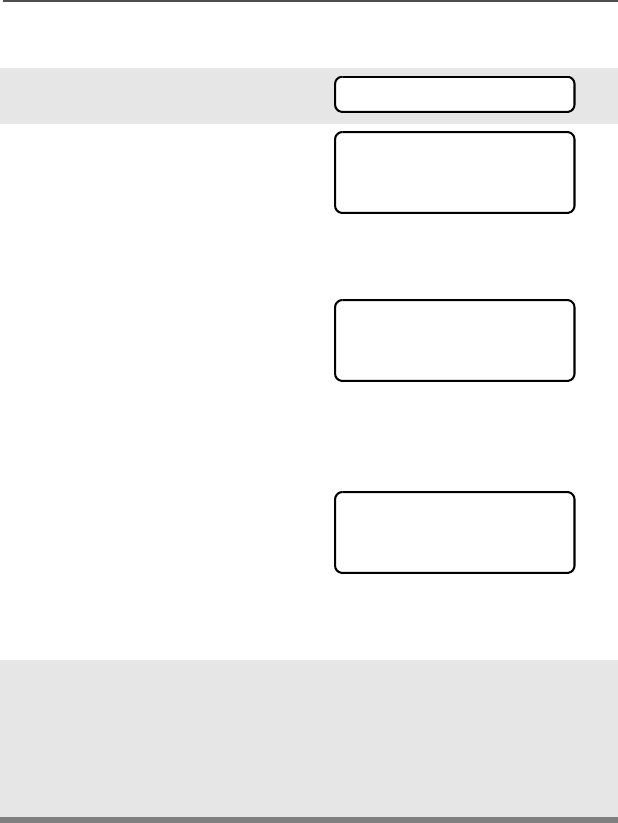
ASTRO Digital XTS 5000 Model III 67
Common Radio Features
Initiate a Call Alert Page
1Press U to find PAGE.
2Press D, E, or F
directly below PAGE.
If an individual Call Alert
page was last transmitted or
received, you see the
individual ID number.
If a group Call Alert page
was last transmitted, you see
blanks in the individual ID
scratchpad and the group ID
transmitted to in the group ID
scratchpad (accessed by
pressing V once).
If a group Call Alert page
was last received, you see
the ID of the sending radio in
the individual ID scratchpad
and the group ID transmitted
to in the group ID
scratchpad.
3Go to “Select an ID Number”
on page 68.
OR
Go to “Send a Call Alert
Page” on page 68.
•Use the Menu
• Use the Keypad
PAGE
FIRE CHIEF
ID: 701234
LIST
FIRE CHIEF
ID: ______
LIST
FIRE DEPT
GR: 704440
LIST
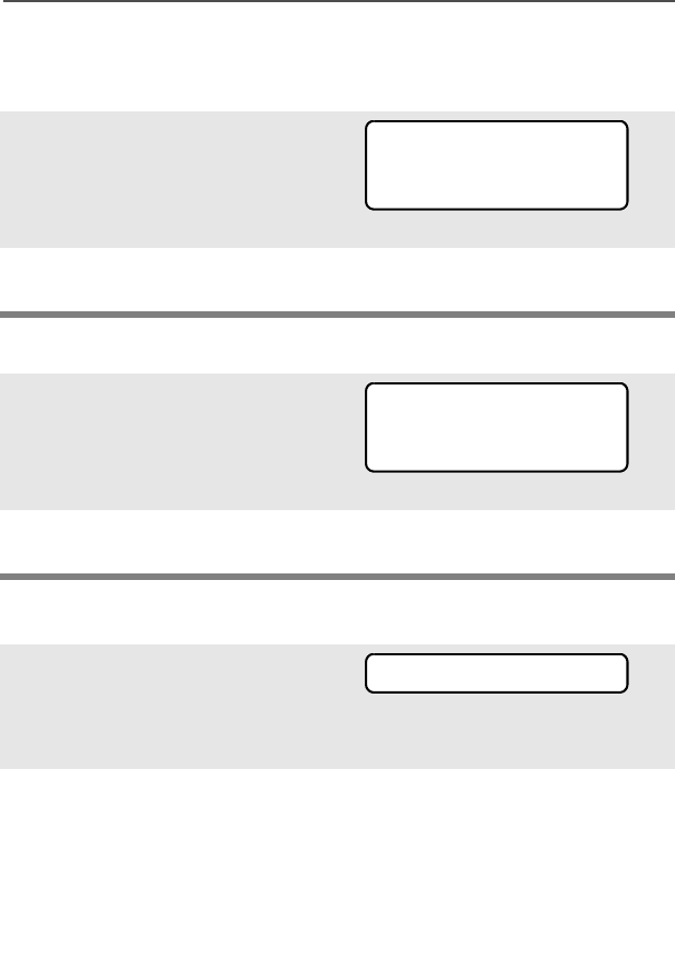
68
Common Radio Features
Select an ID Number
Use the Menu
Use the Keypad
Send a Call Alert Page
1Press U to find the ID
number you want.
Note: Press LNUM to go to the
last number dialed.
2Go to “Send a Call Alert
Page”, below.
1Use the keypad to enter the
ID number you want.
Note: Press LNUM to go to the
last number dialed.
2Go to “Send a Call Alert
Page”, below.
1Press the PTT button to send
the Call Alert to the displayed
number. You see PLEASE
WAIT.
2When you are connected, you
see the home display. Press
and hold the PTT
button to talk; release the
PTT to listen.
OR
FIRE CHIEF
ID: 701234
LNUM
FIRE CHIEF
ID: 701234
LNUM
PLEASE WAIT
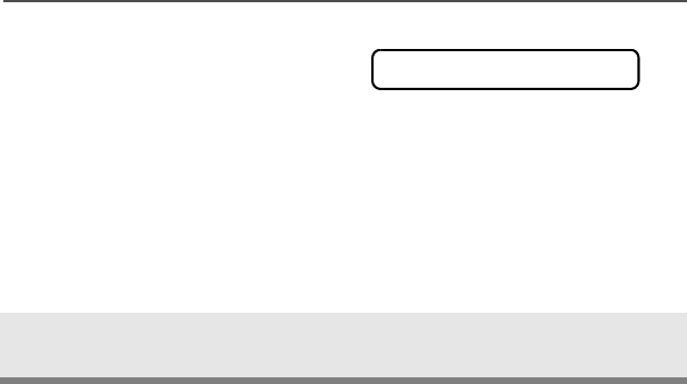
ASTRO Digital XTS 5000 Model III 69
Common Radio Features
If an individual Call Alert
page is not acknowledged,
you see NO ACKNOWLDG.
If a group Call Alert page is
not acknowledged, you do
not see NO ACKNOWLDG. The
radio will merely exit Call
Alert and return to normal
operation.
3Press h to hang up and return
to the home display.
NO ACKNOWLDG
70
Common Radio Features
Conventional Talkgroup Calls (Conventional
Operation Only)
Talkgroup Call lets you define a group of conventional system users
so that they can share the use of a conventional channel.
Encryption keys are slaved to talkgroups. When talkgroups are
enabled, encryption keys are changed by changing the active
talkgroup. See “Secure Operations” on page 77.
Select a Talkgroup
1Press U to find TGRP.
2Press D, E, or F
directly below TGRP. You see
the last talkgroup that was
selected and stored, and SEL
and PSET.
3Press V or U to find the
talkgroup you want.
OR
Use the keypad to enter the
number of the corresponding
talkgroup in the list.
4Press D, E, or F
directly below SEL or PSET.
SEL (SELECT) — Saves the currently displayed talkgroup and
returns to the home display.
PSET (PRESET) — Selects the preset preprogrammed talkgroup.
If the encryption key slaved
to the new talkgroup is
erased, you see KEY FAIL
and hear a momentary key
fail tone.
• Momentary key fail tone
TGRP
SEL PSET
SEL PSET
KEY FAIL

ASTRO Digital XTS 5000 Model III 71
Common Radio Features
If the encryption key that is
slaved to the new talkgroup
is not allowed, you see
ILLEGAL KEY and hear a
momentary key fail tone.
• Momentary key fail tone
5Press h or the PTT button, or
turn the 16-Position Select
knob to exit.
ILLEGAL KEY
72
Common Radio Features
Status Calls (ASTRO 25 Trunking Only)
You can send data calls to the dispatcher about a predefined status.
Each status can have up to a 12-character name. A maximum of eight
status conditions is possible.
Send a Status Call
Use the Menu
1Press U to find STS.
2Press D, E, or F
directly below STS. The last
acknowledged status call, or
the first status in the list, is
displayed.
3Press V or U to find the
status you wish to send.
OR
Use the keypad to enter a
number corresponding to the
location in the status list.
4Press the PTT button to send
the status.
When the dispatcher
acknowledges, four tones
sound, ACK RECEIVED is dis-
played, and the radio returns
to normal dispatch operation.
OR
• Four tones
If no acknowledgment is
received, you will see NO
ACKNOWLDG and hear a low-
pitched tone. • Single tone
5Press h to go to the home
display
STS
ACK RECEIVED
NO ACKNOWLDG

ASTRO Digital XTS 5000 Model III 73
Common Radio Features
Use the Preprogrammed Status Button
Note: No traffic is heard on trunked channels while Status Calls is
selected.
If the radio detects no Status Call activity for six seconds, an
alert tone sounds until h or the PTT button is pressed.
1Press the Status button. The
last acknowledged status
call, or the first status in the
list, is displayed.
2Press V or U to find the
status you wish to send.
OR
Use the keypad to enter a
number corresponding to the
location in the status list.
3Press the PTT button to send
the status.
When the dispatcher
acknowledges, four tones
sound, ACK RECEIVED is dis-
played, and the radio returns
to normal dispatch operation.
OR
• Four tones
If no acknowledgment is
received, you will see NO
ACKNOWLDG and hear a low-
pitched tone. • Single tone
4Press h to go to the home
display
Note: No traffic is heard on trunked channels while Status Calls is
selected.
If the radio detects no Status Call activity for six seconds, an
alert tone sounds until the PTT button is pressed.
ACK RECEIVED
NO ACKNOWLDG
74
Common Radio Features
Repeater or Direct Operation
Also known as “talkaround operation,” DIRECT lets you bypass the
repeater and connect directly to another radio. The transmit and
receive frequencies are the same.
REPEATER operation increases radio’s range by connecting with
other radios through a repeater. The transmit and receive frequencies
are different.
Select Repeater or Direct Operation
Use the Menu
1Press U to find DIR.
2Press D, E, or F
directly below DIR. You
momentarily see the current
operation.
• For Direct mode
• For Repeater mode
OR
3Press D, E, or F
directly below DIR or RPTR.
If DIR is selected, the display
shows r and DIRECT MODE.
OR
Press h to exit without
changing the current
operation.
DIR
DIRECT MODE
DIR RPTR
RPTR MODE
DIR RPTR
r
DIRECT MODE

ASTRO Digital XTS 5000 Model III 75
Common Radio Features
Use the Preprogrammed Repeater/Direct Switch
Place the Repeater/Direct
switch in either the Repeater
or the Direct position. If DIR
is selected, the display
shows r. r

76
Common Radio Features
Smart PTT (Conventional Only)
Smart PTT is a per-channel, programmable feature used in
conventional radio systems to keep radio users from talking over
other radio conversations.
When smart PTT is enabled in your radio, you will not be able to
transmit on an active channel. If you try to transmit on an active
smart-PTT channel, you will hear an alert tone, and the transmission
will be inhibited. The LED will also blink red to indicate that the
channel is busy.
Three radio-wide variations of smart PTT are available:
Transmit Inhibit on
Busy Channel with
Carrier
You cannot transmit if any traffic is
detected on the channel.
Transmit Inhibit on
Busy Channel with
Wrong Squelch Code
You cannot transmit on an active channel
with a squelch code or (if secure-
equipped) encryption key other than your
own. If the PL code is the same as yours,
the transmission will not be prevented.
Quick-Key Override This feature can work in conjunction with
either of the two above variations. You
can override the transmit-inhibit state by
quick-keying the radio. In other words,
two PTT Button presses within the
preprogrammed time limit.

ASTRO Digital XTS 5000 Model III 77
Special Radio Features
Secure Operations
Secure radio operation provides the highest commercially available
level of voice security on both trunked and conventional channels.
Unlike other forms of security, Motorola digital encryption provides
signaling that makes it virtually impossible for others to decode any
part of an encrypted message.
Note: Secure operation is not available in trunked analog modes.
Select Secure Transmissions
Select Clear Transmissions
Turn the preprogrammed
Secure/Clear switch to the
secure position (D).
Note: If the selected channel
is programmed for clear-
only operation — when
you press the PTT
button, you see CLR TX
ONLY, and you hear an
invalid mode tone.
• Invalid mode tone
The radio will not transmit until you set the Secure/
Clear switch to the clear position (E).
Turn the preprogrammed Secure/Clear switch to the clear
position (E).
Note: If the selected channel
is programmed for
secure-only operation —
when you press the PTT
button, you see SEC TX
ONLY, and you hear an
invalid mode tone.
• Invalid mode tone
The radio will not transmit until you set the Secure/
Clear switch to the secure position (D).
c
CLR TX ONLY
SEC TX ONLY

78
Special Radio Features
Managing Encryption
Key Loading
Refer to the key-variable loader (KVL) manual for equipment
connections and setup.
Multikey
The multikey feature allows your radio to be equipped with as many
as 48 different encryption keys and supports the DES-OFB algorithm.
•Conventional Multikey — The encryption keys can be tied
(strapped), on a one-per-channel basis, through radio service
software. In addition, you can have operator-selectable keys,
operator-selectable keysets, and operator-selectable key erasure.
If talkgroups are enabled in conventional, then the encryption keys
are strapped to the talkgroups.
•Trunked Multikey — If you use your radio for both conventional
and trunked applications, you will have to strap your encryption
keys for trunking on a per-talkgroup or announcement-group
basis. In addition, you may strap a different key to other features
1Attach the KVL to your radio.
When it is attached, the
display will show
KEYLOADING, and all other
radio functions, except for
power down, backlight, and
volume, will be locked out.
2Press the PTT button on the
KVL. This will load the
encryption keys into your
radio. When the key has
been loaded successfully,
the radio will sound a short
tone for single-key radios; for
multikey radios, an
alternating tone will be
heard.
KEYLOADING
ASTRO Digital XTS 5000 Model III 79
Special Radio Features
for example, dynamic regrouping, failsoft, or emergency talkgroup.
You can have operator-selectable key erasure.
Key Selection
1Press U until KEY appears
on the display.
2Press D, E, or F
directly below KEY. The
display changes to show the
last user-selected and stored
encryption key and the
available menu selections.
3Press V or U to scroll
through the encryption keys.
OR
Enter the number of the
desired key using the
keypad.
Note: If an erased key is selected, the key name will be
alternated with ERASED KEY.
4Press D, E, or F
directly below the desired
menu selection.
OR
If you selected the key via
the keypad, press V or
U to scroll through the
menu selections:
PSET or PRESET = selects the preset or default encryption key.
SEL = saves the newly selected key and returns to the home
display.
KEY
HW KEY 1
PSET
SEL ABRT
80
Special Radio Features
Keyset Selection
This feature allows you to select one or more groups of several
encryption keys from among the available keys stored in the radio.
For example, you could have a group of three keys structured to one
keyset, and another group of three different keys structured to
another keyset; by changing keysets, you would automatically switch
from one set of keys to the other. Every channel to which one of the
original keys was tied to will now have the equivalent new key
instead.
5Press h, the PTT button, the
ABRT menu selection, or turn
the 16-Position Select knob
to exit this menu.
Note: If the selected key is
erased, KEY FAIL will
be displayed and a
momentary keyfail
tone will be
generated.
If the selected key is
not allowed, ILLEGAL
KEY will be displayed
and a momentary
illegal key tone,
similar to the key fail
tone, will be
generated.
1Press U until KSET
appears on the display.
2Press D, E, or F
directly below KSET. The
display changes to show the
last user-selected and stored
keyset and the available
keyset menu selections.
KEY FAIL
ILLEGAL KEY
KSET
KEYSET 1
SEL
KS1 KS2

ASTRO Digital XTS 5000 Model III 81
Special Radio Features
3Press D, E, or F
directly below the desired
keyset.
OR
Enter the number of the
desired keyset using the
keypad.
4To save the newly selected
keyset, press the button
directly below SEL. The radio
will then exit keyset selection
and return to the home
display.
Note: Press h, the PTT button, the ABRT menu selection, or turn
the 16-Position Select knob to exit this menu at any time
without changing the keyset selection.
82
Special Radio Features
Key Zeroization
This enables the user to erase all or selected encryption keys.
Use the Menu
1Press U until the display
shows ERAS.
2Press D, E, or F
directly below ERAS. The
display shows the last user-
selected and stored
encryption key, and the
available menu selections:
ALL = erases all the encryp-
tion keys in the radio. The
display shows ERS ALL
KEYS and YES and NO.
SNGL = selects the displayed
encryption key to be erased.
The display shows ERS SNGL
KEY and YES and NO.
ABRT = exits this menu and
returns to the home display.
Note: Press h, the PTT button, the ABRT menu selection, or turn
the 16-Position Select knob to exit this menu at any time
without erasing any keys.
ERAS
ALL
SNGL ABRT
ERS ALL KEYS
YES NO
ERS SNGL KEY
YES NO

ASTRO Digital XTS 5000 Model III 83
Special Radio Features
3Press D, E, or F
directly below the desired
menu selection.
OR
Press V or U to find the
desired encryption key. The
display shows the selected
key, and the available menu
selections shown in step 2.
Press D, E, or F
directly below the desired
menu selection.
OR
Enter the location number of
the desired key, using the
keypad. The display shows
the selected key, and the
available menu selections
shown in step 2. Press D,
E, or F directly below
the desired menu selection.
4Press h, the PTT button, the
ABRT menu selection, or turn
the 16-Position Select knob
to exit this menu.
84
Special Radio Features
Use the Buttons
Note: This is the method used for erasing the single key in radios
with the single-key option, and for erasing all keys in radios
with the multikey option.
1With the radio on, press and
hold the Top Side button;
while holding this button
down, press the Top button.
Note: DO NOT press the
Top button before
pressing the Top Side
button, unless you are
in an emergency
situation; this would
send an emergency
alarm.
2Before the keys are erased,
the display shows PLEASE
WAIT.
3When all the encryption keys
have been erased, the
display shows ERASED.
PLEASE WAIT
ERASED
ASTRO Digital XTS 5000 Model III 85
Special Radio Features
Over-the-Air Rekeying (Rekey Request) (ASTRO Conventional
Only)
The over-the-air rekeying (OTAR) feature allows the dispatcher to
reprogram the encryption keys in the radio remotely. The dispatcher
performs the rekey operation upon receiving a rekey request from the
user.
Use the Menu
1Press U to find REKY.
2Press D, E, or F directly
below REKY.
3Press the PTT to send the
rekey request.
Note: Pressing the PTT again, or the Home or Emergency
button, will exit the feature and allow the user to
transmit in the normal manner.
4If the display shows REKEY
FAIL and a bad-key tone
sounds, the rekey operation has
failed.
Note: If this occurs, your radio does not contain the Unique
Shadow Key (USK). This key must be loaded into the
radio with the key-variable loader (KVL) before the
rekey request can be sent. Refer to your local key
management supervisor for more information.
REKY
REQUEST REKY
PLEASE WAIT
REKEY FAIL

86
Special Radio Features
Digital PTT ID
Receive
This feature allows you to see the radio ID number of the radio you
are currently receiving. This ID can be a maximum of eight characters
and can be viewed by both the receiving radio and the dispatcher.
Transmit
Your radio’s ID number is automatically sent every time the PTT
button is pressed. This is a per-channel feature. For digital voice
transmissions, your radio’s ID is sent continuously during the voice
message.
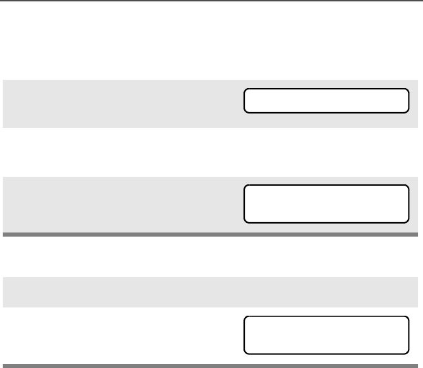
ASTRO Digital XTS 5000 Model III 87
Special Radio Features
View Your Radio’s ID Number
Use the Menu
Use the Preprogrammed Call or Page Button
1Press U to find CALL or
PAGE.
2Press D, E, or F directly
below CALL or PAGE.
3Press V.
1Press the Call or Page button.
2Press V.
CALL PAGE
MY ID:
701111
MY ID:
701111

88
Special Radio Features
Dynamic Regrouping (Trunking Only)
The dynamic regrouping feature lets the dispatcher temporarily
reassign selected radios to a single special channel so they can
communicate with each other. This feature is typically used during
special operations and is enabled by a qualified radio technician. You
will not notice whether your radio has this feature enabled until a
dynamic regrouping command is sent by the dispatcher.
Note: If you try to access a zone or channel that has been reserved
by the dispatcher as a dynamically regrouped mode for other
users, you will hear an invalid tone.
Reprogram Request (ASTRO 25 Trunking Only)
This feature lets you notify the dispatcher that you want a new
dynamic regrouping assignment.
Use the Menu
When your radio is dynamically regrouped, it automatically
switches to the dynamically regrouped channel. You see the
dynamically regrouped channel’s name, and hear a “gurgle”
tone.
Press the PTT button to talk; release it to listen.
When the dispatcher cancels dynamic regrouping, the radio
automatically returns to the zone and channel that you were
using before the radio was dynamically regrouped.
1Press U to find RPGM.
2Press D, E, or F directly
below RPGM.
The reprogram request is sent
to the dispatcher.
RPGM
REPRGRM RQST

ASTRO Digital XTS 5000 Model III 89
Special Radio Features
Use the Preprogrammed Reprogram Request Button
3If you hear one beep
- Press the PTT button to send
the reprogram request again.
OR
-Press h to cancel and return
to the home display.
OR
If you hear five beeps, the
reprogram request was
acknowledged by the dis-
patcher. Your radio returns to
the home display.
OR
If the dispatcher does not
acknowledge the reprogram
request within six seconds, you
see NO ACKNOWLDG and hear a
low-pitched alert tone.
Try again or press h.
• An alert tone
1Press the Reprogram
Request button. You see
REPRGRM RQST.
The reprogram request is sent
to the dispatcher.
NO ACKNOWLDG
REPRGRM RQST

90
Special Radio Features
Select Enable / Disable
The dispatcher can classify regrouped radios into either of two
categories: Select Enabled or Select Disabled.
• Select-enabled radios are free to change to any available channel,
including the dynamic-regrouping channel, once the user has
selected the dynamic-regrouping position.
• Select-disabled radios cannot change channels while dynamically
regrouped. The dispatcher has forced the radio to remain on the
dynamic-regrouping channel.
The Scan or Private Call feature cannot be selected while your radio
is Select Disabled.
2If you hear one beep
- Press the PTT button to send
the reprogram request again
OR
-Press h to hang up and
return to the home display.
OR
• One beep
If you hear five beeps, the
reprogram request was
acknowledged by the dis-
patcher. Your radio returns to
the home display.
OR
• Five beeps
If the dispatcher does not
acknowledge the reprogram
request within six seconds, you
see NO ACKNOWLDG and hear a
low-pitched alert tone.
Try again or press h.
• An alert tone
NO ACKNOWLDG

ASTRO Digital XTS 5000 Model III 91
Special Radio Features
Trunking System Controls
Failsoft
The failsoft system ensures continuous radio communications during
a trunked system failure. If a trunking system fails completely, the
radio goes into failsoft operation and automatically switches to its
failsoft channel.
During failsoft operation:
When the trunking system returns to normal operation, your radio
automatically leaves failsoft operation and returns to trunked
operation.
Out-of-Range
If you go out of the range of the system and can no longer lock onto a
control channel:
Your radio transmits and receives
in conventional operation on a
predetermined frequency.
You hear a medium-pitched tone
every 10 seconds.
• A medium-pitched tone
You see the currently selected
zone/channel combination and
OUT OF RANGE.
AND/OR
You hear a low-pitched tone.
AND/OR
• A tone
Your radio remains in this out-of-
range condition until it locks onto a
control channel, or it locks onto a
failsoft channel, or it is turned off.
• Locks onto a control
channel, or
• Locks onto a failsoft
channel, or
• Turned off.
FAILSOFT
OUT OF RANGE
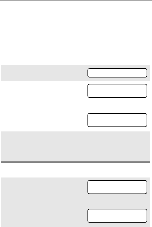
92
Special Radio Features
Site Lock
This feature allows your radio to lock onto a specific site and not roam
among wide-area talkgroup sites. This feature should be used with
caution, since it inhibits roaming to another site in a wide-area
system.
Lock or Unlock a Site
Use the Menu
Use the Preprogrammed Site Lock/Unlock Button
1Press U to find SITE.
2Press D, E, or F directly
below SITE. The current lock
state is displayed.
OR
3Press D, E, or F directly
below the desired lock state,
LOCK or UNLK.
• The new site lock state is
saved.
• Your radio returns to the
home display.
1Press the Site Lock/Unlock
button. The current lock state is
momentarily displayed.
OR
SITE
SITE UNLOCKD
LOCK UNLK
SITE LOCKED
LOCK UNLK
SITE UNLOCKD
LOCK UNLK
SITE LOCKED
LOCK UNLK

ASTRO Digital XTS 5000 Model III 93
Special Radio Features
Site Trunking
If the zone controller loses communication with any site, that site
reverts to site trunking.
When this occurs, you can communicate only with other radios within
your trunking site.
2Press and hold the Site Lock/
Unlock button to find the
desired lock state, SITE
UNLOCKD or SITE LOCKED.
You see the currently selected
zone/channel combination and
SITE TRUNKNG.
SITE TRUNKNG

94
Special Radio Features
Site View and Change
You can view the number of the current site or force your radio to
change to a new one.
View the Current Site
Change the Current Site
Press the preprogrammed Site
Search button.
The display momentarily
shows the name of the current
site and its corresponding
received signal strength indica-
tor (RSSI). (See Table 4 on
page 5.)
OR
If the radio is scanning for a
new site, you momentarily see
SCANING SITE.
Press and hold down the pre-
programmed Site Search but-
ton. You momentarily see
SCANING SITE and hear a
tone.
• A tone
When the radio finds a new
site, it returns to the home dis-
play.
s
SITE 2
SCANING SITE
SCANING SITE
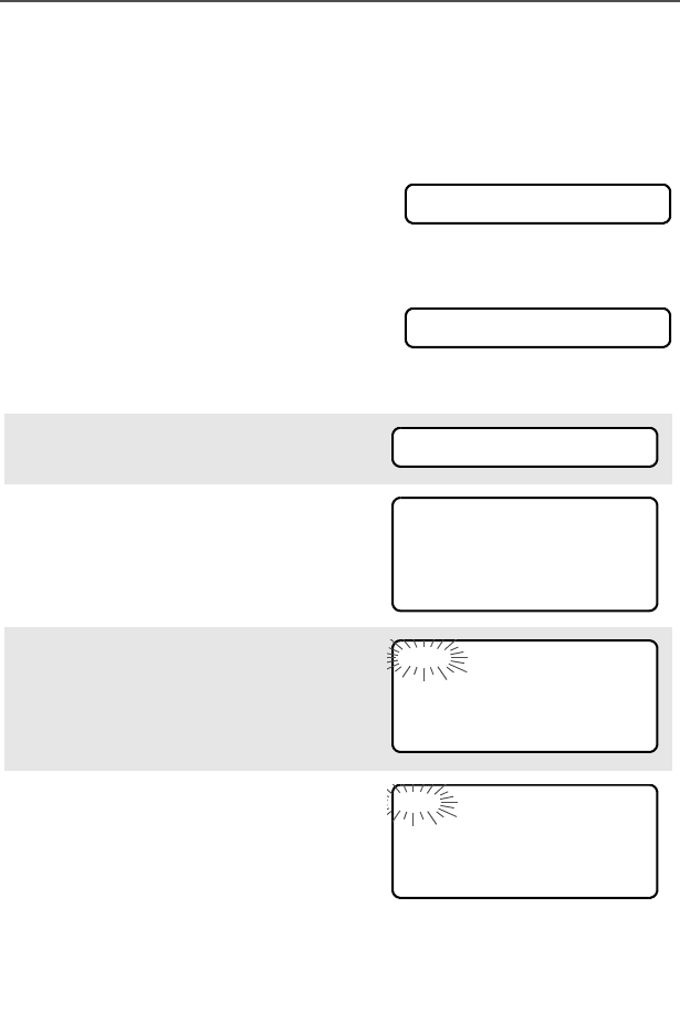
ASTRO Digital XTS 5000 Model III 95
Special Radio Features
Time and Date
Using this special feature, you can program the time and date as you
might with other electronic devices. The clock display is enabled by a
qualified radio technician.
- The default time setting is a 12-hour
clock.
- If a 24-hour clock is selected, AM/PM
selection is not available.
- The default setting for the domestic
date shows MDY.
Edit the Time and Date
1Press U to find CLCK.
2Press D, E, or F directly
below CLCK. The current setting
is displayed.
3Press D, E, or F directly
below EDIT. The first item
flashes.
4Press X or Y to change the
selected item.
Note: Press h at any time to return to the home display
without saving your changes.
OR
12HR 00:00AM
MDY 00/00/00
CLCK
12HR 03:54AM
MDY 03/07/02
EDIT
12HR 03:54AM
MDY 03/07/02
SAVE
24HR 03:54AM
MDY 03/07/02
SAVE
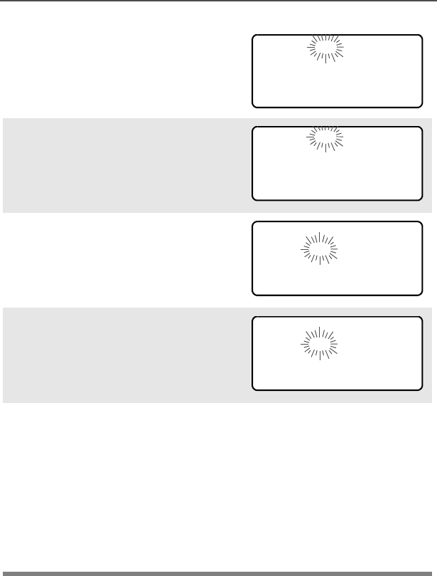
96
Special Radio Features
Press U one or more times
to move to an item you wish to
change.
5Press X or Y to change the
selected item.
6Press U one or more times to
move to an item in the date
field.
7Press X or Y to change the
selected item.
8When you have made all your
changes, press D, E, or
F directly below SAVE to
save your changes and return
to the home display.
Note: If a call arrives while the radio is in the clock-setting
menu, the radio exits clock setting, your changes are
lost, and the call information is displayed.
24HR 03:54AM
MDY 03/07/02
SAVE
24HR 03:58AM
MDY 03/07/02
SAVE
24HR 03:58AM
MDY 03/07/02
SAVE
24HR 03:58AM
MDY 03/08/02
SAVE

ASTRO Digital XTS 5000 Model III 97
Helpful Tips
Radio Care
Things to Avoid
• The XTS 5000 radio casting has two vent ports
that allow for pressure equalization in the radio.
Never poke these vents with any objects, such
as needles, tweezers, or screwdrivers. This
could create leak paths into the radio and the
radio’s submergibility will be lost.
•(For XTS 5000 R Radios Only) The XTS 5000
R radio is designed to be submerged to a
maximum depth of 6 feet, with a maximum
submersion time of 4 hours. Exceeding either
maximum limit may result in damage to the
radio.
• If the radio battery contact area has been
submerged in water, dry and clean the radio
battery contacts before attaching a battery to the
radio. Otherwise, the water could short-circuit
the radio.
• If the radio has been submerged in water, shake
the radio well so that any water that may be
trapped inside the speaker grille and
microphone port can be removed. Otherwise,
the water will decrease the audio quality of the
radio.
• Do not disassemble the radio. This could
damage radio seals and result in leak paths into
the radio. Any radio maintenance should be
performed only by a qualified radio technician.
!
C a u t i o n

98
Helpful Tips
Cleaning
To clean the external surfaces of your radio:
1Combine one teaspoon of mild dishwashing detergent to one
gallon of water (0.5% solution).
2Apply the solution sparingly with a stiff, non-metallic, short-
bristled brush, making sure excess detergent does not get
entrapped near the connectors, controls or crevices. Dry the
radio thoroughly with a soft, lint-free cloth.
3Clean battery contacts with a lint-free cloth to remove dirt or
grease.
Handling
• Do not pound, drop, or throw the radio unnecessarily. Never carry
the radio by the antenna.
• Avoid subjecting the radio to an excess of liquids. Do not
submerge the radio unless it is a ruggedized, XTS 5000 R model.
• Avoid subjecting the radio to corrosives, solvents or spirits.
• Do not disassemble the radio.
• Keep the accessory-connector cover in place until ready to use
the connector. Replace the cover immediately once the accessory
has been disconnected.
Do not use solvents to clean your radio. Spirits
may permanently damage the radio housing.
Do not submerge the radio in the detergent
solution.
!
C a u t i o n

ASTRO Digital XTS 5000 Model III 99
Helpful Tips
Service
Proper repair and maintenance procedures will assure efficient
operation and long life for this product. A Motorola maintenance
agreement will provide expert service to keep this and all other
communication equipment in perfect operating condition. A
nationwide service organization is provided by Motorola to support
maintenance services. Through its maintenance and installation
program, Motorola makes available the finest service to those
desiring reliable, continuous communications on a contract basis. For
a contract service agreement, please contact your nearest Motorola
service or sales representative, or an authorized Motorola dealer.
Express Service Plus (ESP) is an optional extended service coverage
plan, which provides for the repair of this product for an additional
period of either one or two years beyond the normal expiration date of
the standard warranty. For more information about ESP, contact the
Motorola Radio Support Center at 3761 South Central Avenue,
Rockford, IL 61102 (800) 227-6772 / (847)725-4200.

100
Helpful Tips
Battery
Battery Life
Battery life is determined by several factors. Among the more critical
are the regular overcharge of batteries and the average depth of
discharge with each cycle. Typically, the greater the overcharge and
the deeper the average discharge, the fewer cycles a battery will last.
For example, a battery which is overcharged and discharged 100%
several times a day, will last fewer cycles than a battery that receives
less of an overcharge and is discharged to 50% per day. Further, a
battery which receives minimal overcharging and averages only 25%
discharge, will last even longer.
Charging the Battery
Motorola batteries are designed specifically to be used with a
Motorola charger and vice-versa. Charging in non-Motorola
equipment may lead to battery damage and void the battery warranty.
Motorola-authorized battery chargers may not charge batteries other
than the ones listed on page 105.
The battery should be at about 77°F (25°C) (room temperature),
whenever possible. Charging a cold battery (below 50° F [10°C]) may
result in leakage of electrolyte and ultimately in failure of the battery.
Charging a hot battery (above 95°F [35°C]) results in reduced
discharge capacity, affecting the performance of the radio. Motorola
rapid-rate battery chargers contain a temperature-sensing circuit to
ensure that batteries are charged within the temperature limits stated
above.
Battery Charge Status
Your radio can indicate your battery’s charge status through:
• LED and sounds
• conventional fuel gauge symbol on the display
• smart fuel gauge symbol on the display

ASTRO Digital XTS 5000 Model III 101
Helpful Tips
LED and Sounds
When your battery is low:
• you see the LED flash red when the PTT button is pressed
• you hear a low-battery “chirp” (short, high-pitched tone)
Conventional Fuel Gauge Symbol
A flashing fuel gauge symbol (b) is displayed only when the
battery voltage drops to low level. In this case, replace the battery
with a fully charged one.
Smart Fuel Gauge Symbol
Consult the Smart Battery manual. All conditions must be met for a
battery to be classified as a “Smart Battery.” When your radio has a
Smart Battery installed, the fuel gauge symbol is always displayed.
Replace the battery with a fully charged one when the fuel gauge
shows the lowest level.
Battery Recycling and Disposal
Nickel-cadmium (NiCd) rechargeable batteries can be recycled.
However, recycling facilities may not be available in all areas. Under
various U.S. state laws and the laws of several other countries, NiCd
batteries must be recycled and cannot be disposed of in landfills or
incinerators. Contact your local waste management agency for
specific requirements and information in your area.
Motorola fully endorses and encourages the recycling of NiCd
batteries. In the U.S. and Canada, Motorola participates in the
Gauge shows if the battery’s charge is
b71% to 100% full
j41% to 70%
k11% to 40%
l10% or less (at 10%, the gauge begins flashing)

102
Helpful Tips
nationwide Rechargeable Battery Recycling Corporation (RBRC)
program for NiCd battery collection and recycling. Many retailers and
dealers participate in this program.
For the location of the drop-off facility closest to you, access RBRC's
Internet web site at www.rbrc.com or call 1-800-8-BATTERY. This
internet site and telephone number also provide other useful
information concerning recycling options for consumers, businesses,
and governmental agencies.
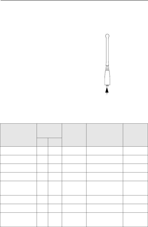
ASTRO Digital XTS 5000 Model III 103
Helpful Tips
Antenna
Radio Operating Frequencies
The following antenna types are compatible with your radio:
Before installing the antenna,
make sure it matches your
radio’s operating frequency.
Antennas are frequency
sensitive and are color coded
according to their frequency
range. The color code indicator
is located in the center of the
antenna’s base.
Antenna Type
Approx.
Length Insulator
Color
Code
Frequency
Range
Antenna
Kit No.
in. mm
VHF Helical 8 203 RED 136-174 MHz NAD6563
VHF Helical 7.6 193 YELLOW 136-150.8 MHz NAD6566
VHF Helical 7 178 BLACK 150.8-162 MHz NAD6567
VHF Helical 6.5 165 BLUE 162-174 MHz NAD6568
800MHz Whip,
Halfwave
7 178 RED 806-870 MHz NAF5037
UHF Helical 3.4 88 RED 380-435 MHz NAE6546
UHF Helical 3.2 80 GREEN 435-470 MHz NAE6547
UHF Whip,
Wideband
5.2 130 GRAY 380-520 MHz NAE6549
MAEPF-27478-O
Color Code

104
Helpful Tips
Antenna Type Approx.
Length
Insulator
Color
Code
Frequency
Range
Antenna
Kit No.
800MHz
Stubby,
Quarterwave
3.4 86 WHITE 806-870 MHz NAF5042
700/800MHz
Whip
7 178 GREEN 764-870 MHz NAF5080

ASTRO Digital XTS 5000 Model III 105
Accessories
Motorola provides the following approved accessories to improve the
productivity of your XTS 5000 portable two-way radio.
Antennas
Batteries and Battery Accessories
NAD6563 136-174 MHz helical
NAD6566 136-150.8 MHz helical
NAD6567 150.8-162 MHz helical
NAD6568 162-174 MHz helical
NAE6546 380-435 MHz helical
NAE6547 435-470 MHz helical
NAE6549 380-520 MHz wideband whip
NAF5037 800 MHz whip, halfwave (806-870 MHz)
NAF5042 800 MHz stubby, quarterwave (806-870 MHz)
NAF5080 700/800 MHz whip (764-870 MHz)
HNN9031 1525 NiCd smart
HNN9032 1525 NiCd smart FM
NNTN4435 1800 NiMH smart (VHF use only)
NNTN4436 1750 NiMH smart FM (VHF use only)
NTN8294 1525 NiCd, ultra-high capacity
NTN8295 1525 NiCd high-capacity Factory Mutual (FM) Intrinsi-
cally Safe
NTN8297 1525 NiCd high-capacity Factory Mutual (FM) Intrinsi-
cally Safe, Rugged
NTN8299 1750 NiMH ultra-capacity FM
NTN8610 1650 lithium ion
NTN8923 1800 NiMH ultra-capacity
NTN9177 Battery holder, clamshell, black

106
Accessories
Carry Accessories
Belt Clips
Belt Loops
Carry Cases
NTN9183 Battery holder, clamshell, orange
RNN4006 3000 NiMH
RNN4007 3000 NiMH FM
NTN8266 Belt clip kit, 2.25", plastic (compatible with clamshell
batteries)
NTN8460 Public Safety belt clip, metal (VHF use only)
NTN9179 Combo, high-activity D clip (NTN9212) and high-
activity belt loop (NTN9213)
NTN9212 D clip, high-activity, swivel
NTN8039 Swivel belt loop, 2.5" (for use only with the high-activ-
ity leather swivel snap carry cases)
NTN8040 Belt loop, swivel, leather, 3.0", high-activity (for use
only with the high-activity leather swivel snap carry
cases)
NTN8383 T-strap, plain, action snaps
NTN9213 Belt loop, 2.5", high-activity, D clip
NTN8380 Case, hard leather high-activity (includes swivel belt
loop and T-strap), 2.5" belt loop, for Model II and III
radios
NTN8381 Case, hard leather high-activity (includes swivel belt
loop and T-strap), 3.0" belt loop, for Model II and III
radios

ASTRO Digital XTS 5000 Model III 107
Accessories
Chargers
NTN8382 Case (includes belt loop and T-strap), for Model II
and III radios
NTN8384 Case, leather high-activity (includes T-strap)
NTN8385 Case, hard leather high-activity (includes swivel belt
loop and T-strap), 2.5" belt loop, for Model I radio
NTN8386 Case, hard leather high-activity (includes swivel belt
loop and T-strap), 3.0" belt loop, for Model I radio
NTN8387 Case (includes belt loop and T-strap), for Model I
radio
NTN8725 Case, nylon (includes T-strap)
NTN9184 Case (includes belt loop), for clamshell battery
NTN1177 Multi-unit, dual rate, rapid, 110 V
NTN1178 Multi-unit, dual rate, rapid, 220 V (2-prong Euro plug)
NTN1179 Multi-unit, dual rate, rapid, 240V (UK 13 MAP plug)
NTN1667 Single-unit, tri-chemistry, rapid rate, 110 V
NTN1668 Single-unit, tri-chemistry, rapid rate, 230 V (2-prong
Euro plug)
NTN1669 Single-unit, tri-chemistry, rapid rate, 230 V (3-prong
UK plug)
NTN1873 Single-unit, dual rate, rapid, tri-chemistry, 110 V
NTN1874 Single-unit, dual rate, rapid, tri-chemistry, 220 V (2-
prong Euro plug)
NTN1875 Single-unit, dual rate, rapid, tri-chemistry, 240 V (3-
prong UK plug)
NTN4796 Multi-unit, tri-chemistry, rapid rate, 110 V
WPLN4111_R Impres single-unit, 110 V
WPLN4120_R Impres multi-unit, 110 V

108
Accessories
Enhanced and Multi-Unit Line Cords
Surveillance Accessories
Earpieces
NTN7373 110 V interchangeable line
NTN7374 220 V interchangeable line (2-prong Euro plug)
NTN7375 240 V interchangeable line (3-prong UK plug)
BDN6641 Ear mic, high noise level up to 105 dB, grey (must
order BDN6671 interface module)
BDN6664 Earpiece with standard earphone, beige
BDN6665 Earpiece with extra-loud earphone (exceeds OSHA
limits), beige
BDN6666 Earpiece with volume control, beige
BDN6667 Earpiece, mic and PTT combined, beige
BDN6668 Earpiece, mic and PTT separate, beige
BDN6669 Earpiece, mic and PTT combined, with extra-loud
earphone (exceeds OSHA limits), beige
BDN6670 Earpiece, mic and PTT separate with extra-loud ear-
phone (exceeds OSHA limits), beige
BDN6677 Ear mic, standard, noise up to 95 dB (must order
BDN6671 interface module), black
BDN6678 Ear mic, standard, noise up to 95 dB (must order
BDN6671 interface module), beige
BDN6726 Earpiece with standard earphone, black
BDN6727 Earpiece with extra-loud earphone (exceeds OSHA
limits), black
BDN6728 Earpiece with volume control, black
BDN6729 Earpiece, mic and PTT combined, black

ASTRO Digital XTS 5000 Model III 109
Accessories
Headsets and Headset Accessories
BDN6730 Earpiece, mic and PTT separate, black
BDN6731 Earpiece, mic and PTT combined, with extra-loud
earphone (exceeds OSHA limits), black
BDN6732 Earpiece, mic and PTT separate, with extra-loud
earphone (exceeds OSHA limits), black
BDN6780 Earbud, single with Mic and PTT combined, beige
BDN6781 Earbud, single, receive only, black
BDN6635 Heavy-duty VOX headset with noise-canceling
boom mic (requires BDN6673 adapter)
BDN6636 Heavy-duty VOX headset with throat mic (requires
BDN6673)
BDN6645 Noise-canceling boom mic headset with PTT on
earcup
BDN6673 Headset adapter cable (for use with BDN6635 and
BDN6645)
BDN6676 Jedi adapter
NMN1020 Safety helmet headset (requires BDN6676 adapter)
NMN6245 Light-weight headset
NMN6246 Ultralite headset with boom mic
NMN6258 Over-the-head headset with in-line PTT
NMN6259 Medium-weight, dual headset with NC mic
NTN8613 Keyload adapter
RMN4049 Jedi “TEMCO” temple transducer

110
Accessories
Radio Interface Modules for Ear Microphones
Speaker, Remote Speaker and Public Safety
Microphones
Commport Integrated Microphone/Receivers
BDN6671 Push-to-talk (PTT) and voice-activated (VOX) inter-
face module (for use with BDN6641, BDN6677 and
BDN6678)
BDN6708 PTT interface module (for use with BDN6641,
BDN6677 and BDN6678)
NMN6191 RSM noise-canceling (includes 6.0' coiled cord
assembly, 3.5mm earjack, swivel clip, quick discon-
nect)
NMN6193 Remote speaker mic
NMN6247 Public safety mic with straight cord, 30"
NMN6250 Public safety mic with straight cord, 24"
NMN6251 Public safety mic with straight cord, 18"
ZMN6031 Speaker mic, 3-piece
ZMN6032 Speaker mic, 2-piece
ZMN6038 Speaker mic, 2-piece, extra loud
ZMN6039 Speaker mic, 3-piece, extra loud
NTN1624 Commport with palm PTT
NTN1625 Commport ear mic with PTT for noise levels up to
100 dB (requires BDN6676 adapter)
NTN1663 Commport ear mic with ring PTT for noise levels up
to 100 dB (requires BDN6676 adapter)
NTN1736 Commport ear mic with snap-on side PTT for noise
levels up to 100 dB (requires BDN6676 adapter)

ASTRO Digital XTS 5000 Model III 111
Accessories
Switches
Vehicular Adapters
Accessories
Allied Models
0180300E83 Remote PTT body switch
NTN7660 Tilt / man down switch
NTN8327 External RF switch
HMN4069 Next-generation mobile mic
HSN1006 Speaker, 6-watt
NKN6455 Cable, 6-watt speaker
NTN1606 Vehicular adapter, BNC, open face
NTN1607 Vehicular adapter, BNC, closed face
NTN8560 Vehicular adapter, mini-U, open face
NTN8561 Vehicular adapter, mini-U, closed face
NTN8940 Vehicular adapter, trunnion mount
NTN9176 Vehicular charger, XTS, tri-chemistry, compatible with
PAC•RT
PLN7737 Handheld control head
N1799 Vehicular adapter, mini-U, closed face
N2001 Vehicular adapter, mini-U, open face
N2002 Vehicular adapter, BNC, open face
N2003 Vehicular adapter, BNC, closed face

112
Accessories
Notes

ASTRO Digital XTS 5000 Model III 113
Glossary
This is a list of specialized terms used in this manual.
ACK Acknowledgment of communication.
Active Channel A channel that has traffic on it.
Analog Signal An RF signal that has a continuous nature
rather than a pulsed or discrete nature.
ASTRO 25 Trunking Motorola standard for wireless digital
trunked communications.
ASTRO
Conventional
Motorola standard for wireless analog or
digital conventional communications.
Autoscan A feature that allows the radio to
automatically scan the members of a scan
list.
Call Alert Privately page an individual by sending an
audible tone.
Carrier Squelch Feature that responds to the presence of an
RF carrier by opening or unmuting (turning
on) a receiver’s audio circuit. A squelch
circuit silences the radio when no signal is
being received so that the user does not
have to listen to “noise.”
Central Controller A software-controlled, computer-driven
device that receives and generates data for
the trunked radios assigned to it. It monitors
and directs the operations of the trunked
repeaters.
Channel A group of characteristics such as transmit/
receive frequency pairs, radio parameters,
and encryption encoding.
Control Channel In a trunking system, one of the channels
that is used to provide a continuous, two-
way/data communications path between the
central controller and all radios on the
system.

114
Glossary
Conventional Typically refers to radio-to-radio
communications, sometimes through a
repeater (see Trunking).
Conventional Scan
List
A scan list that includes only conventional
channels.
Cursor A visual tracking marker (a blinking line) that
indicates a location on the display.
Deadlock Displayed by the radio after three failed
attempts to unlock the radio.The radio must
be powered off and on prior to another
attempt.
Digital Private Line
(DPL)
A type of coded squelch using data bursts.
Similar to PL except a digital code is used
instead of a tone.
Digital Signal An RF signal that has a pulsed, or discrete,
nature, rather than a continuous nature.
Dispatcher An individual who has radio system
management duties.
Dynamic Regrouping A feature that allows the dispatcher to
temporarily reassign selected radios to a
single special channel so they can
communicate with each other.
Failsoft A feature that allows communications to
take place even though the central controller
has failed. Each trunked repeater in the
system will transmit a data word informing
every radio that the system has gone into
failsoft.
FCC Federal Communications Commission.
Hang Up Disconnect.
Home Display The first display information after the radio
completes its self test.

ASTRO Digital XTS 5000 Model III 115
Glossary
KVL Key-variable loader: A device for loading
encryption keys into the radio.
LCD Liquid crystal display.
LED Light-emitting diode.
Menu Entry A software-activated feature shown at the
bottom of the display — selection of these
features is controlled by the D, E, and
F buttons.
Monitor Check channel activity by pressing the
Monitor button. If the channel is clear, you
will hear static. If the channel is in use, you
will hear conversation. It also serves as a
way to check the volume level of the radio,
since the radio will “open the squelch” when
pressing the monitor button.
Network Access
Code
Network Access Code (NAC) operates on
digital channels to reduce voice channel
interference between adjacent systems and
sites.
NiCd Nickel-cadmium
NiMH Nickel-metal-hydride.
Non-tactical/Revert The user will talk on a preprogrammed
emergency channel. The emergency alarm
is sent out on this same channel.
OTAR Over-the-air rekeying.
Page A one-way alert, with audio and/or display
messages.
Personality A set of unique features specific to a radio.
Preprogrammed Refers to a software feature that has been
activated by a qualified radio technician.

116
Glossary
Private
(Conversation) Call
A feature that lets you have a private
conversation with another radio user in the
group.
Private Line (PL) A sub-audible tone that is transmitted such
that only receivers decoding the tone will
receive it.
Programmable Refers to a radio control that can have a
radio feature assigned to it.
PTT Push-To-Talk — the PTT button engages
the transmitter and puts the radio in transmit
(send) operation when pressed.
Radio Frequency
(RF)
The part of the general frequency spectrum
between the audio and infrared light regions
(about 10 kHz to 10,000,000 MHz).
Repeater A conventional radio feature, where you talk
through a receive/transmit facility that re-
transmits received signals, in order to
improve communications range and
coverage.
Selective Call A feature that allows you to call a select
individual, intended to provide privacy and
to eliminate the annoyance of having to
listen to conversations of no interest to you.
Selective Switch Any digital P25 traffic having the correct
Network Access Code and the correct
talkgroup.
Squelch Special electronic circuitry, added to the
receiver of a radio, that reduces, or cuts off,
unwanted signals before they are heard in
the speaker.
Standby An operating condition whereby the radio’s
speaker is muted but still continues to
receive data.

ASTRO Digital XTS 5000 Model III 117
Glossary
Status Calls Pre-defined text messages that allow the
user to send a conditional message without
talking.
Tactical/Non-revert The user will talk on the channel that was
selected before the radio entered the
emergency state.
Talkaround Bypass a repeater and talk directly to
another unit for easy local unit-to-unit
communications.
Talkgroup An organization or group of radio users who
communicate with each other using the
same communication path.
Talkgroup Scan List A scan list that can include both talkgroups
(trunked) and channels (conventional).
Trunking The automatic sharing of communications
paths between a large number of users (see
Conventional).
Trunking Priority
Monitor Scan List
A scan list that includes talkgroups that are
all from the same trunking system.
USK Unique Shadow Key.
Zone A grouping of channels.

118
Glossary
Notes

ASTRO Digital XTS 5000 Model III 119
Commercial Warranty
Limited Warranty
MOTOROLA COMMUNICATION PRODUCTS
I. WHAT THIS WARRANTY COVERS AND FOR HOW LONG:
MOTOROLA INC. (“MOTOROLA”) warrants the MOTOROLA
manufactured Communication Products listed below (“Product”)
against defects in material and workmanship under normal use and
service for a period of time from the date of purchase as scheduled
below:
Motorola, at its option, will at no charge either repair the Product (with
new or reconditioned parts), replace it (with a new or reconditioned
Product), or refund the purchase price of the Product during the
warranty period provided it is returned in accordance with the terms of
this warranty. Replaced parts or boards are warranted for the balance
of the original applicable warranty period. All replaced parts of
Product shall become the property of MOTOROLA.
This express limited warranty is extended by MOTOROLA to the
original end user purchaser only and is not assignable or transferable
to any other party. This is the complete warranty for the Product
manufactured by MOTOROLA. MOTOROLA assumes no obligations
or liability for additions or modifications to this warranty unless made
in writing and signed by an officer of MOTOROLA. Unless made in a
separate agreement between MOTOROLA and the original end user
purchaser, MOTOROLA does not warrant the installation,
maintenance or service of the Product.
MOTOROLA cannot be responsible in any way for any ancillary
equipment not furnished by MOTOROLA which is attached to or used
in connection with the Product, or for operation of the Product with
any ancillary equipment, and all such equipment is expressly
excluded from this warranty. Because each system which may use
ASTRO XTS 5000 Portable Units One (1) Year
Product Accessories One (1) Year

120
Commercial Warranty
the Product is unique, MOTOROLA disclaims liability for range,
coverage, or operation of the system as a whole under this warranty.
II. GENERAL PROVISIONS:
This warranty sets forth the full extent of MOTOROLA'S
responsibilities regarding the Product. Repair, replacement or refund
of the purchase price, at MOTOROLA’s option, is the exclusive
remedy. THIS WARRANTY IS GIVEN IN LIEU OF ALL OTHER
EXPRESS WARRANTIES. IMPLIED WARRANTIES, INCLUDING
WITHOUT LIMITATION, IMPLIED WARRANTIES OF
MERCHANTABILITY AND FITNESS FOR A PARTICULAR
PURPOSE, ARE LIMITED TO THE DURATION OF THIS LIMITED
WARRANTY. IN NO EVENT SHALL MOTOROLA BE LIABLE FOR
DAMAGES IN EXCESS OF THE PURCHASE PRICE OF THE
PRODUCT, FOR ANY LOSS OF USE, LOSS OF TIME,
INCONVENIENCE, COMMERCIAL LOSS, LOST PROFITS OR
SAVINGS OR OTHER INCIDENTAL, SPECIAL OR
CONSEQUENTIAL DAMAGES ARISING OUT OF THE USE OR
INABILITY TO USE SUCH PRODUCT, TO THE FULL EXTENT
SUCH MAY BE DISCLAIMED BY LAW.
III. STATE LAW RIGHTS:
SOME STATES DO NOT ALLOW THE EXCLUSION OR LIMITATION
OF INCIDENTAL OR CONSEQUENTIAL DAMAGES OR
LIMITATION ON HOW LONG AN IMPLIED WARRANTY LASTS, SO
THE ABOVE LIMITATION OR EXCLUSIONS MAY NOT APPLY.
This warranty gives specific legal rights, and there may be other
rights which may vary from state to state.
IV. HOW TO GET WARRANTY SERVICE:
You must provide proof of purchase (bearing the date of purchase
and Product item serial number) in order to receive warranty service
and, also, deliver or send the Product item, transportation and
insurance prepaid, to an authorized warranty service location.
Warranty service will be provided by Motorola through one of its
authorized warranty service locations. If you first contact the company

ASTRO Digital XTS 5000 Model III 121
Commercial Warranty
which sold you the Product, it can facilitate your obtaining warranty
service. You can also call Motorola at 1-888-567-7347 US/Canada.
V. WHAT THIS WARRANTY DOES NOT COVER:
A) Defects or damage resulting from use of the Product in other
than its normal and customary manner.
B) Defects or damage from misuse, accident, water, or neglect.
C) Defects or damage from improper testing, operation,
maintenance, installation, alteration, modification, or
adjustment.
D) Breakage or damage to antennas unless caused directly by
defects in material workmanship.
E) A Product subjected to unauthorized Product modifications,
disassemblies or repairs (including, without limitation, the
addition to the Product of non-Motorola supplied equipment)
which adversely affect performance of the Product or
interfere with Motorola's normal warranty inspection and
testing of the Product to verify any warranty claim.
F) Product which has had the serial number removed or made
illegible.
G) Rechargeable batteries if:
• any of the seals on the battery enclosure of cells are
broken or show evidence of tampering.
• the damage or defect is caused by charging or using the
battery in equipment or service other than the Product for
which it is specified.
H) Freight costs to the repair depot.
I) A Product which, due to illegal or unauthorized alteration of
the software/firmware in the Product, does not function in
accordance with MOTOROLA’s published specifications or
the FCC type acceptance labeling in effect for the Product at

122
Commercial Warranty
the time the Product was initially distributed from
MOTOROLA.
J) Scratches or other cosmetic damage to Product surfaces that
does not affect the operation of the Product.
K) Normal and customary wear and tear.
VI. PATENT AND SOFTWARE PROVISIONS:
MOTOROLA will defend, at its own expense, any suit brought against
the end user purchaser to the extent that it is based on a claim that
the Product or parts infringe a United States patent, and MOTOROLA
will pay those costs and damages finally awarded against the end
user purchaser in any such suit which are attributable to any such
claim, but such defense and payments are conditioned on the
following:
A) that MOTOROLA will be notified promptly in writing by such
purchaser of any notice of such claim;
B) that MOTOROLA will have sole control of the defense of such
suit and all negotiations for its settlement or compromise; and
C) should the Product or parts become, or in MOTOROLA’s
opinion be likely to become, the subject of a claim of
infringement of a United States patent, that such purchaser
will permit MOTOROLA, at its option and expense, either to
procure for such purchaser the right to continue using the
Product or parts or to replace or modify the same so that it
becomes non-infringing or to grant such purchaser a credit
for the Product or parts as depreciated and accept its return.
The depreciation will be an equal amount per year over the
lifetime of the Product or parts as established by
MOTOROLA.
MOTOROLA will have no liability with respect to any claim of patent
infringement which is based upon the combination of the Product or
parts furnished hereunder with software, apparatus or devices not
furnished by MOTOROLA, nor will MOTOROLA have any liability for

ASTRO Digital XTS 5000 Model III 123
Commercial Warranty
the use of ancillary equipment or software not furnished by
MOTOROLA which is attached to or used in connection with the
Product. The foregoing states the entire liability of MOTOROLA with
respect to infringement of patents by the Product or any parts thereof.
Laws in the United States and other countries preserve for
MOTOROLA certain exclusive rights for copyrighted MOTOROLA
software such as the exclusive rights to reproduce in copies and
distribute copies of such Motorola software. MOTOROLA software
may be used in only the Product in which the software was originally
embodied and such software in such Product may not be replaced,
copied, distributed, modified in any way, or used to produce any
derivative thereof. No other use including, without limitation,
alteration, modification, reproduction, distribution, or reverse
engineering of such MOTOROLA software or exercise of rights in
such MOTOROLA software is permitted. No license is granted by
implication, estoppel or otherwise under MOTOROLA patent rights or
copyrights.
VII. GOVERNING LAW:
This Warranty is governed by the laws of the State of Illinois, USA.

124
Commercial Warranty
Notes

ASTRO Digital XTS 5000 Model III 125
Index
Numerics
4-way navigation button ................9
A
accessories ...............................105
alert tones ...................................11
antenna .......................................17
radio operating frequencies ...103
antennas ...................................105
App button ....................................8
attach
antenna ...................................17
battery .....................................15
belt clip ....................................18
universal connector cover .......19
B
backlight ........................................5
batteries and battery accessories ...
105
battery .........................................14
charge status ...........................14
conventional fuel gauge symbol
101
LED and sounds ................101
smart fuel gauge symbol ...101
charger ....................................14
charging the battery ..............100
life ..........................................100
recycling and disposal ...........101
belt clip ........................................18
C
call alert paging
answer a call alert page ..........66
initiate a call alert page ...........67
quick access (one-touch) ........65
select an ID number
use the keypad ....................68
use the menu .......................68
send a call alert page ..............68
carry accessories
belt clips ................................ 106
belt loops .............................. 106
carry cases ........................... 106
chargers
enhanced and multi-unit line cords
107
charging the battery .................... 14
common radio features ............... 27
conventional
mode operation ....................... 26
squelch operation
analog options ..................... 33
digital options ...................... 33
talkgroup calls
select a talkgroup ................ 70
D
digital PTT ID
receive .................................... 86
transmit ................................... 86
display .......................................... 4
dynamic regrouping .................... 88
E
edit
call, page, or phone list name . 42
call, page, or phone list number 41
scan list
change the scan list status only
48
use the menu ...................... 43
use the menu and the
preprogrammed select button
45
use the preprogrammed scan list
programming switch and the
menu ................................ 47
edit the date and time ................. 95
emergency
keep alive ................................ 39
send a silent emergency alarm 38
send an emergency alarm ...... 36
send an emergency call .......... 37

126
Index
enable or disable the radio lock
feature (secure radios only) .......31
encryption
key loading ..............................78
key selection ............................79
key zeroization .........................82
use the buttons ....................84
use the menu .......................82
keyset selection .......................80
managing .................................78
multikey ...................................78
OTAR ......................................85
use the menu .......................85
F
failsoft ..........................................91
G
general radio operation .................1
glossary .....................................113
H
helpful tips ...................................97
home button ..................................8
L
LED indicators .............................10
lists ..............................................40
scan list empty .........................40
view a list .................................40
lock or unlock a site
use the menu ...........................92
use the preprogrammed site lock/
unlock button ..........................92
M
menu
entry (softkey) ............................7
entry features ............................8
select buttons ............................7
mute or unmute keypad tones
use the menu .......................... 32
use the preprogrammed keypad
mute button ............................ 32
N
notations used in this manual .......1
O
out-of-range ................................91
P
phone call display and alert prompts
57
physical features of the XTS 5000
model III radio ............................. 3
PL defeat .................................... 34
private calls ................................. 58
answer a private call ............... 59
initiate ...................................... 59
make a private call ..................61
quick access (one-touch) ........ 58
select an ID number
use the keypad .................... 60
use the menu .......................60
programmable controls ................. 3
R
radio
care
cleaning ...............................98
handling ............................... 98
things to avoid ..................... 97
lock
change your password ........30
unlock your radio .................29
on and off ................................ 20
receive / transmit
use preprogrammed monitor
button .....................................25
use preprogrammed volume set
button .....................................24
without using volume set and

ASTRO Digital XTS 5000 Model III 127
Index
monitor buttons ......................24
remove
antenna ...................................17
battery .....................................15
belt clip ....................................18
universal connector cover .......19
repeater or direct operation .........74
reprogram request ......................88
use the preprogrammed reprogram
request button ........................89
request a new dynamic regrouping
using the menu ........................88
S
scan
delete a nuisance channel ......52
scan (conventional only)
make a dynamic priority change ..
53
secure operations .......................77
secure or clear transmissions .....77
select
a channel
method 1: use the 16-position
select knob ........................22
method 2: use the menu ......22
a zone
use the menu .......................21
use the preprogrammed zone
switch ................................21
clear transmissions ..................77
enable / disable .......................90
repeater or direct operation
use the menu .......................74
use the preprogrammed
repeater/direct switch ........75
secure transmissions ...............77
selectable power level
use the menu ..........................27
use the preprogrammed transmit
power level switch ..................28
selective calls
answer a private call ................62
initiate ..................................... 63
make a selective call ............... 64
quick access (one-touch) ........ 62
select an ID number
use the keypad .................... 64
use the menu ...................... 63
send
a status call
use the menu ...................... 72
use the preprogrammed status
button ............................... 73
service ........................................ 99
site
lock ......................................... 92
trunking ................................... 93
view and change
change the current site ........ 94
view the current site ............ 94
smart
battery condition
use the menu ...................... 16
use the preprogrammed smart
battery button ................... 16
PTT (conventional only) .......... 76
special radio features ................. 77
standard accessories .................. 14
status
calls ......................................... 72
symbols ..................................... 5
surveillance accessories ........... 108
Commport integrated microphone/
receivers .............................. 110
earpieces .............................. 108
headsets and headset accessories
............................................. 109
radio interface modules for ear
microphones ........................ 109
speaker, remote speaker and
public safety microphones ... 110
switches .................................... 110
T
telephone calls

128
Index
answer a phone call .................55
initiate ......................................55
make a phone call ...................56
quick access (one-touch) .........54
select a phone number
use the keypad ....................56
use the menu .......................56
time-out timer ..............................35
trunking system controls .............91
turn
scan on or off
use the menu .......................51
use the preprogrammed scan
on/off switch ......................51
the radio off .............................20
the radio on .............................20
U
universal connector cover ...........19
V
vehicular adaptors
accessories ............................111
allied models ..........................111
view your radio’s ID number
use the menu ...........................87
use the preprogrammed call or
page button ............................87
W
warranty ....................................119
Y
your XTS 5000 model III radio ......2
Z
zones and channels ....................21