Motorola Solutions 89FT4865 HAND HELD PORTABLE 2-WAY RADIO User Manual USERS MANUAL
Motorola Solutions, Inc. HAND HELD PORTABLE 2-WAY RADIO USERS MANUAL
UserManual.wiki
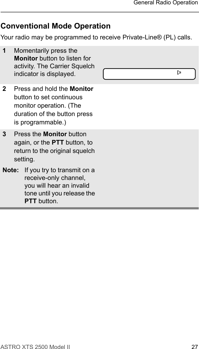
>
Motorola Solutions
>
89FT4865 User Manual
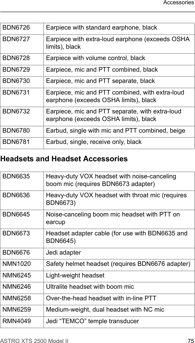
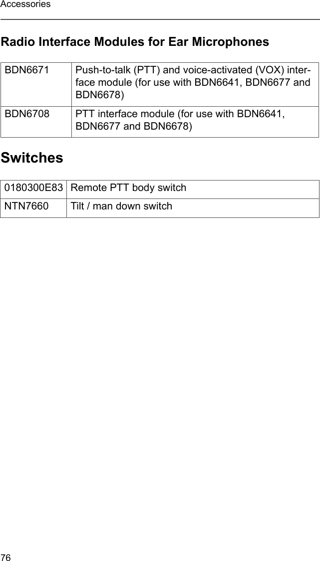
USERS MANUAL
Navigation menu
Upload a User Manual
Namespaces
Wiki Guide
HTML
PDF
Info
Views
User Manual
Discussion / Help
Navigation


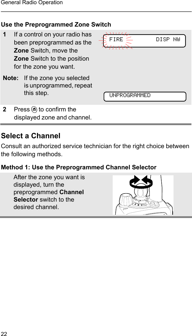
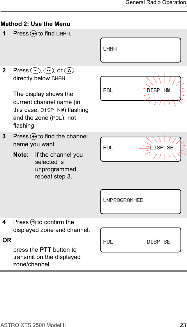
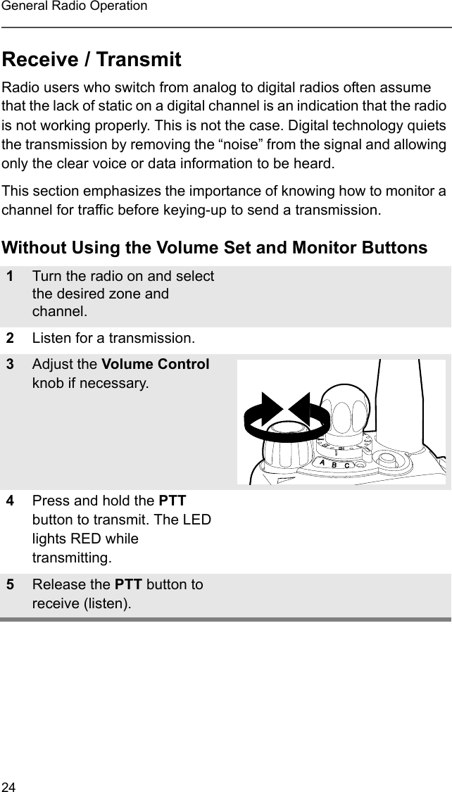
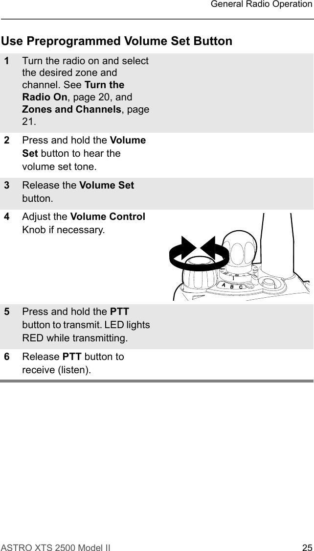
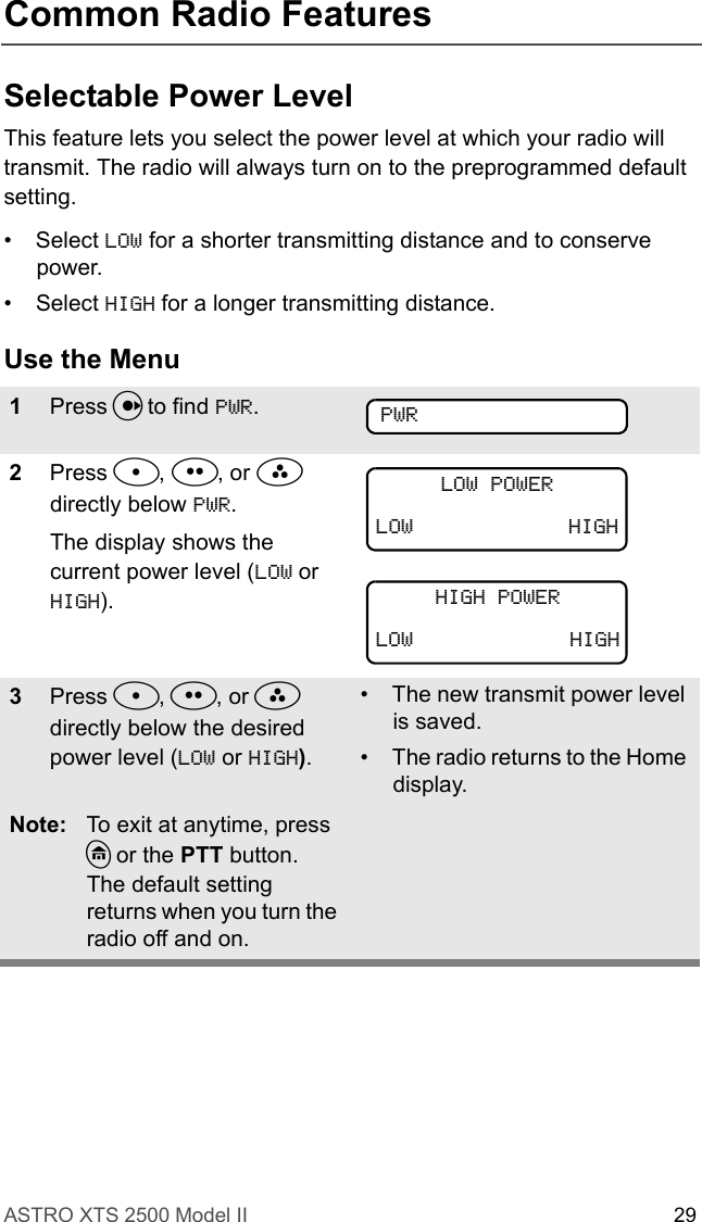
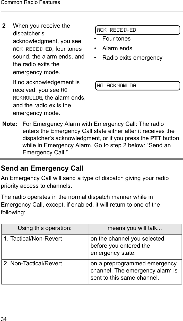
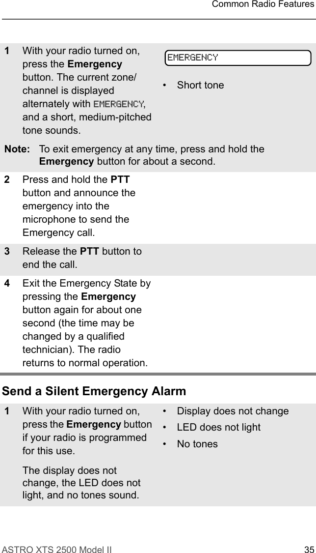
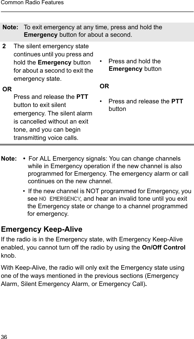
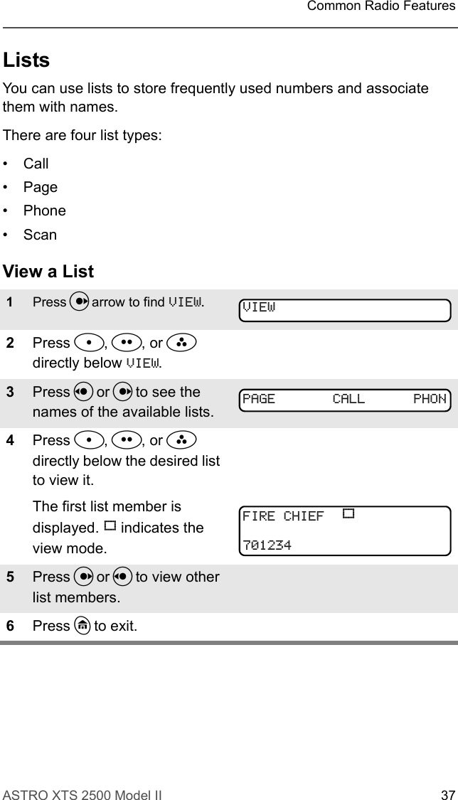
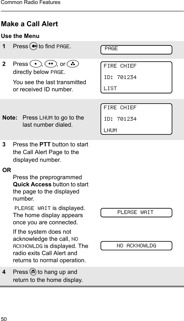
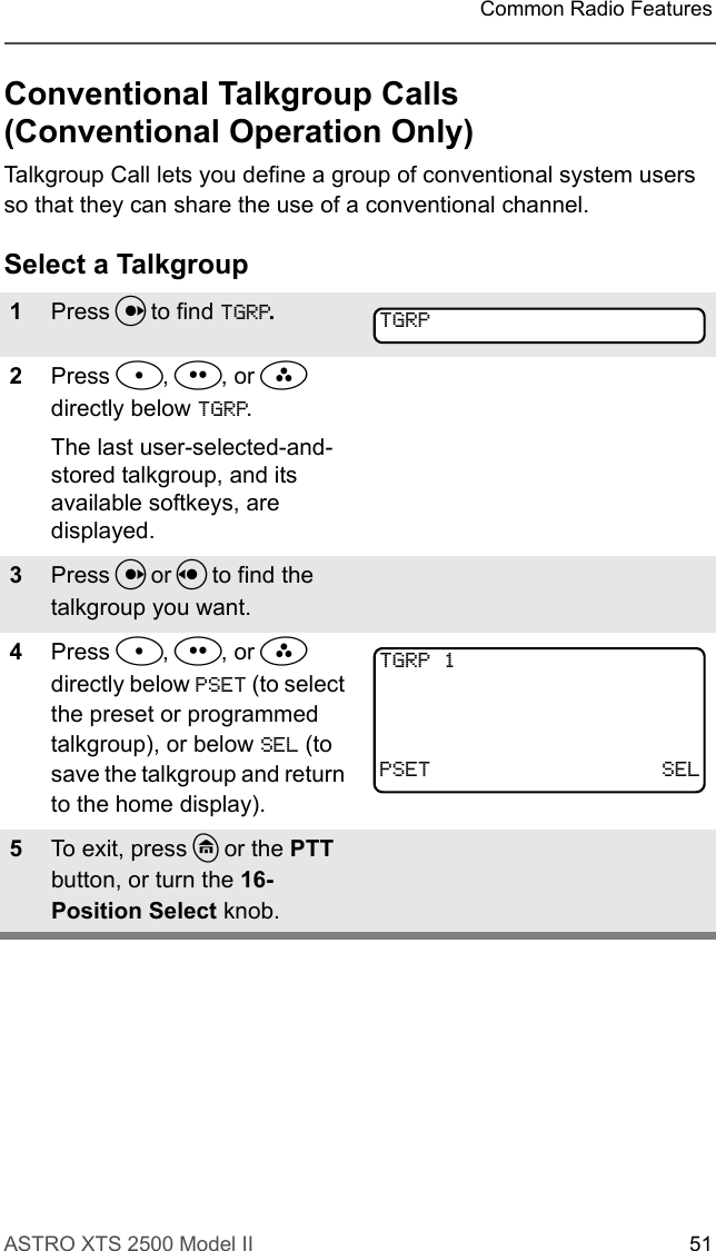
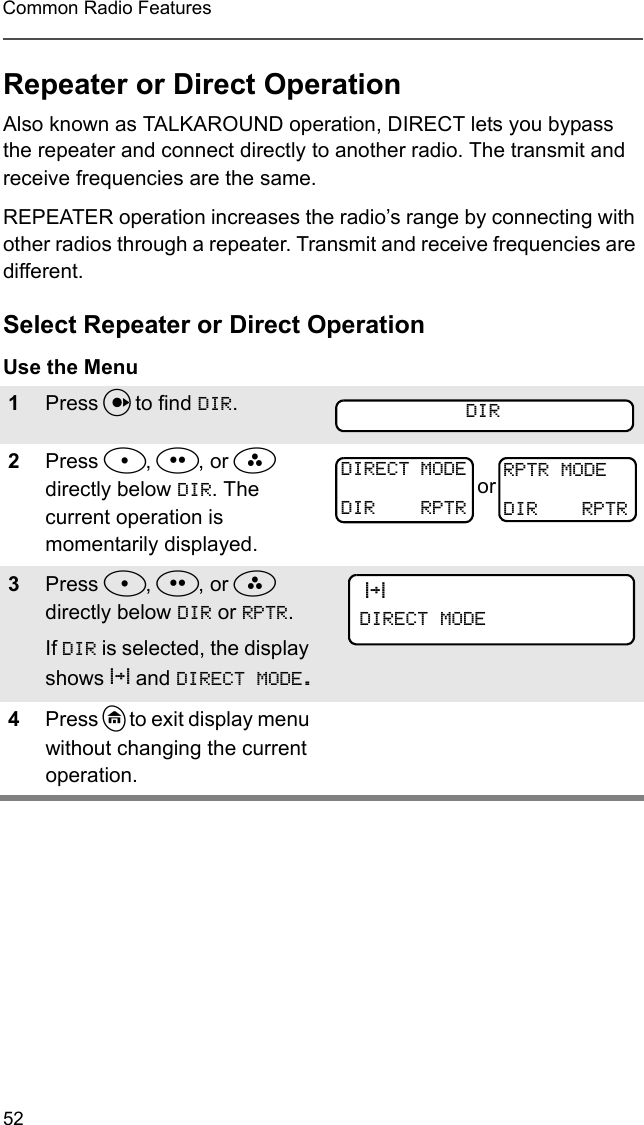
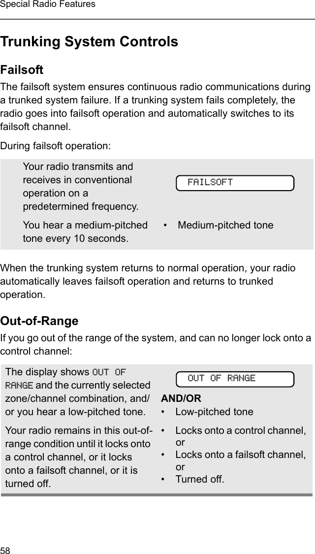
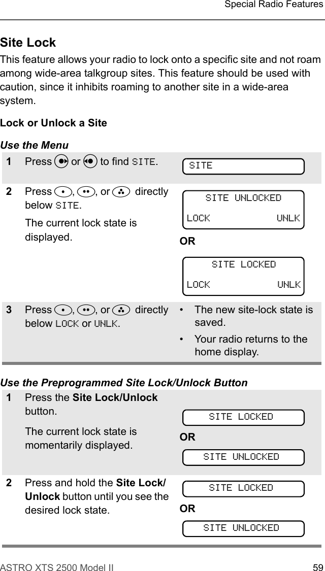
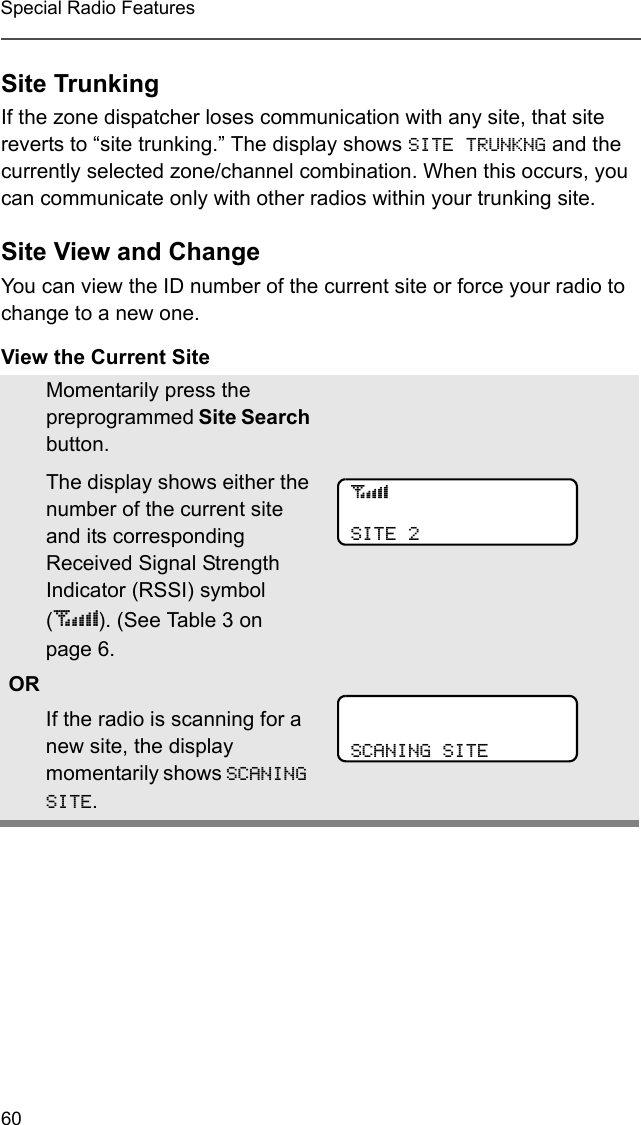
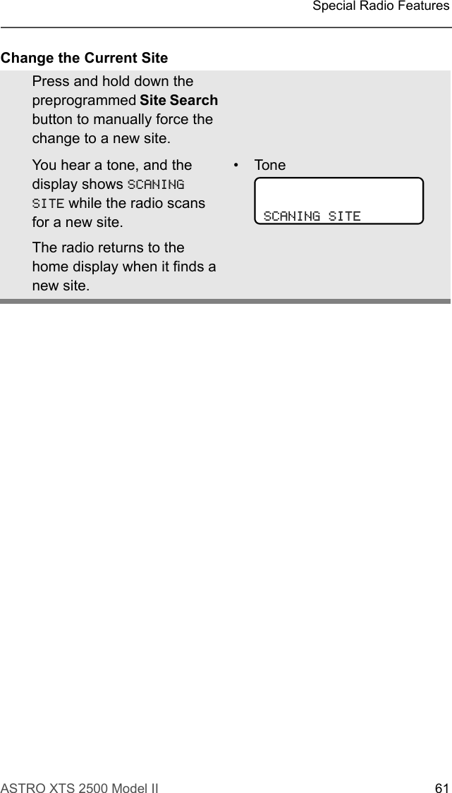
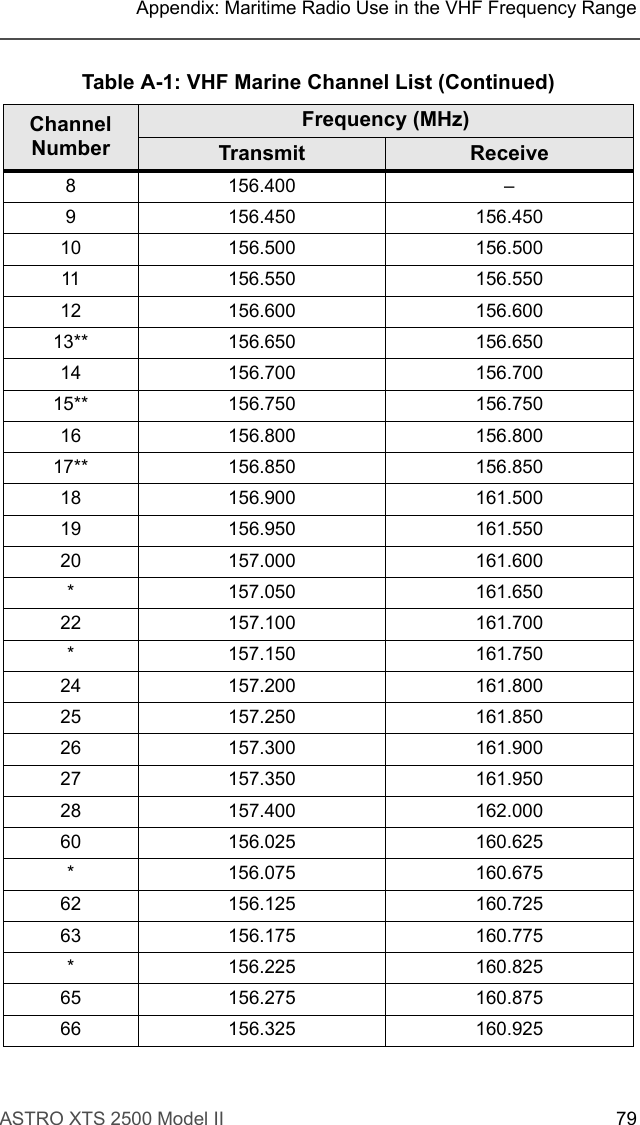
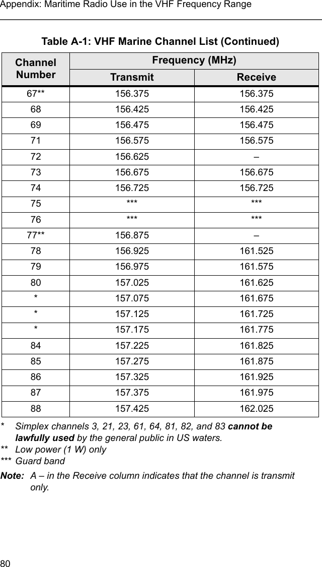
![66Helpful Tipsmaintenance services. Through its maintenance and installation program, Motorola makes available the finest service to those desiring reliable, continuous communications on a contract basis. For a contract service agreement, please contact your nearest Motorola service or sales representative, or an authorized Motorola dealer.Express Service Plus (ESP) is an optional extended service coverage plan, which provides for the repair of this product for a period of three years from the date of shipment from the factory, or the date of delivery if purchased from an authorized Motorola two-way radio dealer. For more information about ESP, contact the Motorola Radio Support Center, 2204 Galvin Drive, Elgin, IL 60123, 1-800-227-6772.BatteryBattery LifeBattery life is determined by several factors. Among the more critical are the regular overcharge of batteries and the average depth of discharge with each cycle. Typically, the greater the overcharge and the deeper the average discharge, the fewer cycles a battery will last. For example, a battery which is overcharged and discharges 100% several times a day, will last fewer cycles than a battery that receives less of an overcharge and is discharged to 50% per day. Further, a battery which receives minimal overcharging and averages only 25% discharge, will last even longer.Charging the Battery Motorola batteries are designed specifically to be used with a Motorola charger and vice-versa. Charging in non-Motorola equipment may lead to battery damage and void the battery warranty. Motorola-authorized battery chargers may not charge batteries other than the ones listed on page 71.The battery should be at about 77°F (25°C) (room temperature), whenever possible. Charging a cold battery (below 50° F [10°C]) may result in leakage of electrolyte and ultimately in failure of the battery. Charging a hot battery (above 95°F [35°C]) results in reduced discharge capacity, affecting the performance of the radio. Motorola](https://usermanual.wiki/Motorola-Solutions/89FT4865/User-Guide-462564-Page-80.png)