Motorola Solutions 89FT4866 HAND HELD PORTABLE 2-WAY R4ADIO User Manual USERS MANUAL
Motorola Solutions, Inc. HAND HELD PORTABLE 2-WAY R4ADIO USERS MANUAL
UserManual.wiki
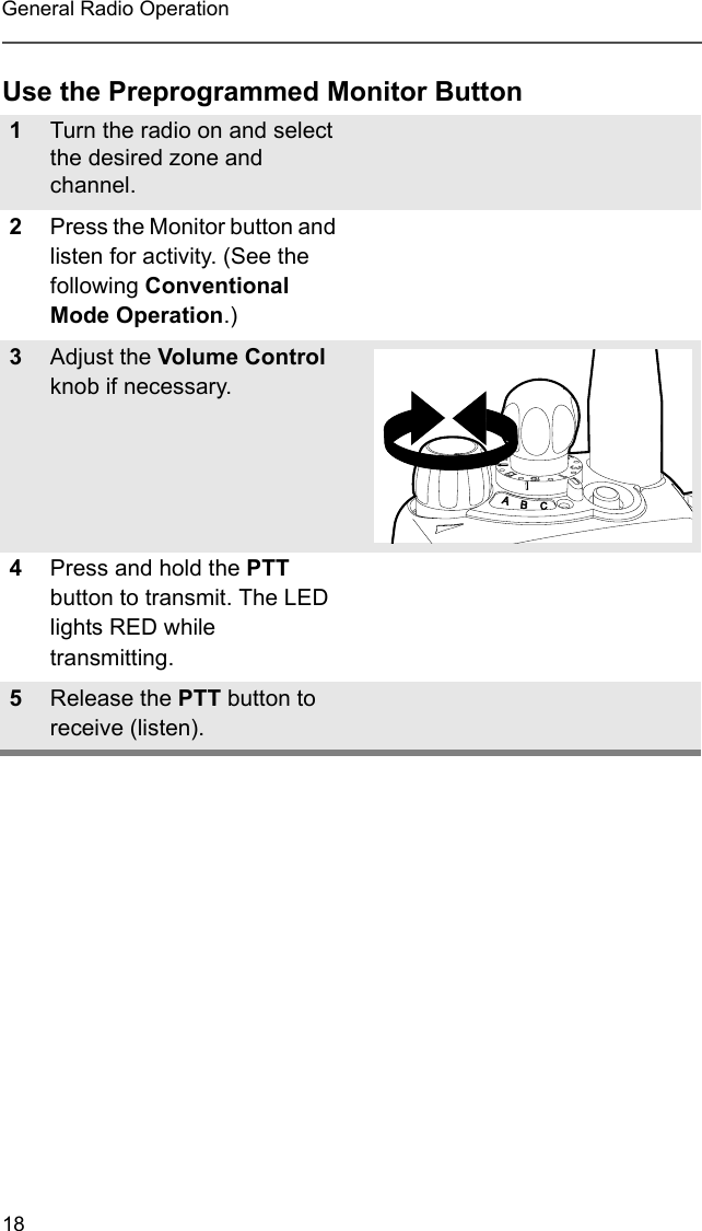
>
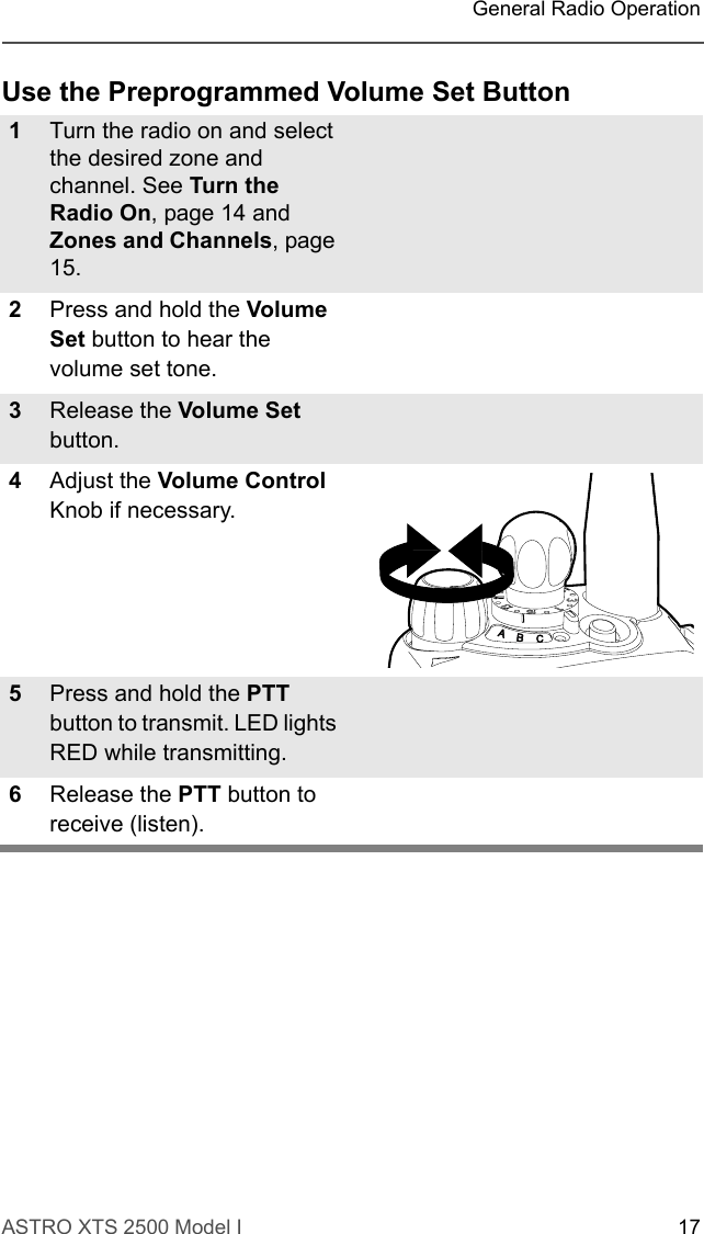
Motorola Solutions
>
89FT4866 User Manual
USERS MANUAL
Navigation menu
Upload a User Manual
Namespaces
Wiki Guide
HTML
PDF
Info
Views
User Manual
Discussion / Help
Navigation
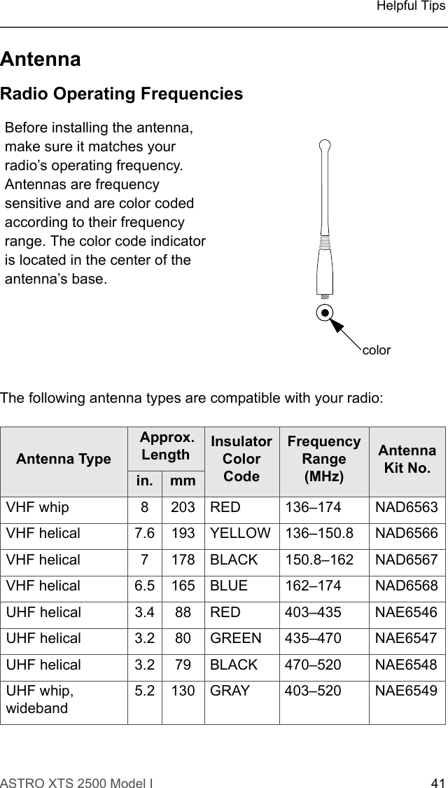
![ASTRO XTS 2500 Model I 39Helpful TipsBatteryBattery LifeBattery life is determined by several factors. Among the more critical are the regular overcharge of batteries and the average depth of discharge with each cycle. Typically, the greater the overcharge and the deeper the average discharge, the fewer cycles a battery will last. For example, a battery which is overcharged and discharges 100% several times a day, will last fewer cycles than a battery that receives less of an overcharge and is discharged to 50% per day. Further, a battery which receives minimal overcharging and averages only 25% discharge, will last even longer.Charging the Battery Motorola batteries are designed specifically to be used with a Motorola charger and vice-versa. Charging in non-Motorola equipment may lead to battery damage and void the battery warranty. Motorola-authorized battery chargers may not charge batteries other than the ones listed on page 43.The battery should be at about 77°F (25°C) (room temperature), whenever possible. Charging a cold battery (below 50° F [10°C]) may result in leakage of electrolyte and ultimately in failure of the battery. Charging a hot battery (above 95°F [35°C]) results in reduced discharge capacity, affecting the performance of the radio. Motorola rapid-rate battery chargers contain a temperature-sensing circuit to ensure that batteries are charged within the temperature limits stated above.Battery Charge StatusYour radio can indicate your battery’s charge status via LED indications and sounds: • you see the LED flash red when the PTT button is pressed, indicating low battery• you hear a low-battery “chirp” (short, high-pitched tone)](https://usermanual.wiki/Motorola-Solutions/89FT4866/User-Guide-468250-Page-51.png)