Motorola Solutions 89FT4869 Automatic Meter Reader (AMR) User Manual AMR RF Transmitter Owner s Manual
Motorola Solutions, Inc. Automatic Meter Reader (AMR) AMR RF Transmitter Owner s Manual
Exhibit 8 Users Manual

a
Owner’s Manual
Automatic Meter
Reader
RF Transmitter
6802973C65-A
MOTOROLA and the Stylized M Logo are
registered in the U.S. Patent and Trademark Office.
All other product or service names are the property
of their respective owners.
Co
py
ri
g
ht © 2004 Motorola All Ri
g
hts Reserved
6802973C65-A
@6802973C65@
COMMERCIAL WARRANTY (STANDARD)
Motorola radio communications products are warranted to be free from defects
in material and workmanship for a period of ONE (1) YEAR, (except for
crystals and channel elements which are warranted for a period of ten (10)
years), from the date of shipment. Parts, including crystals and channel
elements, will be replaced free of charge for the full warranty period but the
labor to replace defective parts will only be provided for one Hundred-Twenty
(120) days from the date of shipment. Thereafter purchaser must pay for the
labor involved in repairing the product or replacing the parts at the prevailing
rates together with any transportation charges to or from the place where
warranty service is provided. This express warranty is extended by Motorola
Communications and Electronics Inc., 1301 E. Algonquin Road, Schaumburg,
Illinois 60196, to the original purchaser only, and only to those purchasing for
purpose of leasing or solely for commercial, industrial, or governmental use.
THIS WARRANTY IS GIVEN IN LIEU OF ALL OTHER WARRANTIES
EXPRESS OR IMPLIED WHICH ARE SPECIFICALLY EXCLUDED,
INCLUDING WARRANTIES OF MERCHANTABILITY OR FITNESS FOR A
PARTICULAR PURPOSE. IN NO EVENT SHALL MOTOROLA BE LIABLE
FOR INCIDENTAL OR CONSEQUENTIAL DAMAGES TO THE FULL
EXTENT SUCH MAY BE DISCLAIMED BY LAW.
In the event of a defect, malfunction or failure to conform to specifications
established by seller, or if appropriate, to specifications accepted by Seller in
writing, during the period shown, Motorola, at its option, will either repair or
replace the product or refund the purchase price thereof, and such action on
the part of Motorola shall be the full extent of Motorola’s liability hereunder.
This warranty is void if:
a. the product is used in other than its normal and customary manner;
b. the product has been subject to misuse, accident neglect or damage;
c. unauthorized alterations or repairs have been made, or unapproved
parts used in the equipment.
This warranty extends only to individual products, batteries are excluded, but
carry their own separate limited warranty. Because each radio system is
unique, Motorola disclaims liability for range, coverage, or operation of the
system as a whole under this warranty except by a separate written agreement
signed by an officer of Motorola.
Non-Motorola manufactured products are excluded from this warranty, but
subject to the warranty provided by their manufacturers, a copy of which will be
supplied to you on specific written request.
In order to obtain performance of this warranty, purchaser must contact its
Motorola salesperson or Motorola at the address first above shown, attention
Quality Assurance Department.
This warranty applies only within the United States.
COMPUTER SOFTWARE COPYRIGHTS
The Motorola products described in this instruction manual may include
copyrighted Motorola computer programs stored in semi conductor memories
or other media. Laws in the United States and other countries preserve for
Motorola certain exclusive rights for copyrighted computer programs including
the exclusive right to copy or reproduce in any form the copyrighted computer
program. Accordingly, any copyrighted Motorola computer programs
contained in the Motorola products described in this instruction manual may
not be copied or reproduced in any manner without the express written
permission of Motorola. Furthermore, the purchase of Motorola products shall
not be deemed to grant either directly or by implication, estoppel, or otherwise,
any license under the copyrights, patents or patent applications of Motorola,
except for the normal non-exclusive, royalty free license to use that arises by
operation of law in the sale of a product.

i
CONTENTS
INTRODUCTION .......................................................... 1
SCOPE OF THIS MANUAL........................................................ 1
THE AMR SYSTEM - OVERVIEW ........................................... 1
GENERAL DESCRIPTION ......................................................... 3
INSTALLATION............................................................ 5
GENERAL ............................................................................... 5
CHANGING THE TRANSMITTER PARAMETERS ....................... 6
ENABLING THE TRANSMITTER ............................................... 6
Without the AMR ToolBox ................................................. 6
With the AMR ToolBox ...................................................... 8
RECORDING COUNTER VALUES/READINGS........................... 9
Initial Recording................................................................ 9
Subsequent Recording during Reprogramming................. 9
DIMENSIONS ........................................................................ 11
WALL MOUNTING ................................................................ 11
PIT INSTALLATION ............................................................... 14
CONNECTIONS...................................................................... 18
Data Connection.............................................................. 18
Programming Connection ............................................... 18
THE AMR RF TRANSMITTER ................................ 19
OVERVIEW ........................................................................... 19
COMMUNICATION ................................................................ 20
CONNECTORS ....................................................................... 20
INTERNAL BATTERY ............................................................ 20
Contents
ii
APPENDIX A: SPECIFICATIONS............................ 23
TRANSMISSION .................................................................... 23
POWER SOURCE ................................................................... 23
INTERFACE TO PULSE TYPE METER..................................... 24
ENVIRONMENTAL ................................................................ 24
FORM FACTOR ..................................................................... 24
PIT INSTALLATION KIT ........................................................ 25
APPENDIX B: MODELS AND ACCESSORIES ..... 27
GENERAL ............................................................................. 27
APPENDIX C: THE AMR TOOLBOX ..................... 29
PROGRAMMING THE TRANSMITTER ..................................... 29
CONNECTING THE TRANSMITTER TO THE TOOLBOX ........... 29
TRANSMITTER PARAMETERS ............................................... 31
ENABLING THE TRANSMITTER ............................................. 32
TESTING THE TRANSMITTER ................................................ 32
FORCING A TRANSMISSION .................................................. 33
APPENDIX D: BATTERY REPLACEMENT .......... 35
REPLACING THE BATTERY ................................................... 35

1
INTRODUCTION
Scope of this Manual
This manual provides instructions for the installation and
operation of the Automatic Meter Reader (AMR) RF
Transmitter. For more information on testing and
programming the RF Transmitter, see the online help of
the AMR ToolBox.
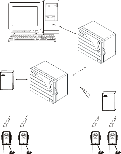
The AMR System - Overview
The Automatic Meter Reader (AMR) system consists of
remote units which collect meter information from the
field and relay it to the host computer, via a network of
intermediaries.
The AMR RF transmitter reads meter information and
transmits it to a receiver in the AMR concentrator, over
radio communication. When the distance between the
transmitter and the receiver extends beyond the coverage
area, a repeater should be added to forward the meter
information to the receiver. The AMR concentrator
forwards the meter readings to the AMR Field Interface
Unit (FIU). The FIU collect the meter readings from a
number of concentrators and forwards the data to the Host
for processing. The Host application computer acts as a
master station, communicating with units over various
communication links.
Figure 1 provides a general view of the AMR System.
Introduction
2
RF
Transmitters
Repeater
Meters
Field Interface Unit
Host
28367
Concentrator
Receiver
RS232
RS232
MDLC
28367
28367
28367
Figure 1
Automatic Meter Reader –System View
The AMR concentrator and FIU are based on the Motorola
MOSCAD/MOSCAD-L units. For more information on
the MOSCAD/MOSCAD-L, see the System Overview
manual of the MOSCAD Programming ToolBox.
General Description
The AMR RF transmitter is a standalone unit used to
transmit meter information from a single pulse-type meter
to the AMR system for processing.
The AMR transmitter is designed to transmit meter
information for at least ten years without power source
replacement. The calculated battery life estimate is thirteen
Introduction
3
years, based on six transmissions per day, zero repetitions,
in 70º F temperatures.
The transmitter consists of a printed circuit board installed
in a plastic case, suitable for either wall mounting or pit
installation. The transmitter is intended for outdoor
installation.
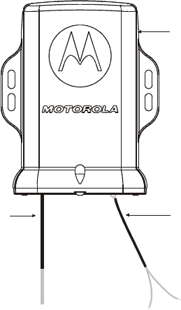
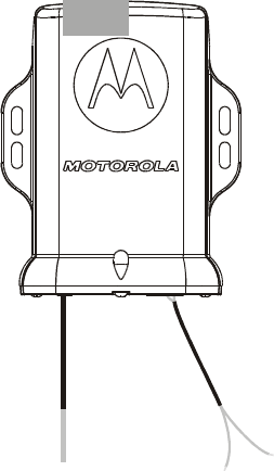
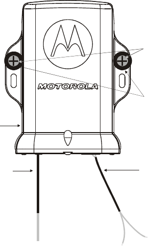
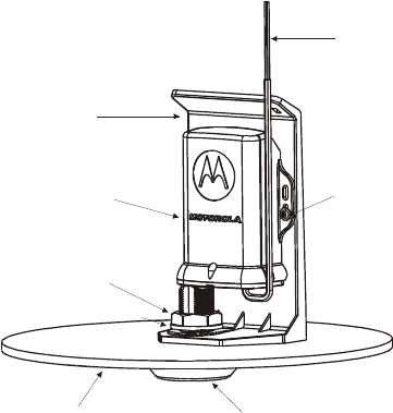
Figure 2 provides a general view of the transmitter.
Data
W
ires
A
ntenna
W
ire
AMR RF
Transmitter
Figure 2
AMR Transmitter – General View
Introduction
4
Safety Handling Instructions
For information on safety handling instructions, see the
Product Safety and RF Energy Exposure for AMR RF
Transmitters booklet, Motorola publication no.
6802974C60, which is distributed with the transmitter.

5
INSTALLATION
General
SAFETY SUMMARY
NOTICE: It is recommended that the transmitter be
installed such that the antenna and the
transmitter are kept 7.8 in (20 cm) from
passersby when transmitting.
The AMR RF transmitter should be installed by
qualified and authorized technicians.
Federal regulations forbid air transport of an
enabled transmitter. If an enabled transmitter
is to be transported by air, the transmitter
housing must be opened and the battery
terminals and capacitor must be unsoldered.
The installation of the AMR RF transmitter includes the
following steps, which should be performed in order
below:
1. Programming any changes to the transmitter
parameters, if necessary;
2. Enabling the transmitter;
3. Installing the transmitter (either on the wall or in a
pit);
4. Recording transmission counter values/meter readings
and forwarding them to the host.

Installation
6
Changing the Transmitter Parameters
The AMR RF transmitter is configured in the factory. If
this configuration needs to be modified, use the AMR
ToolBox to change the parameters, as necessary. For more
information, see Appendix C below and the AMR
ToolBox User Guide.
Enabling the Transmitter
!
C a u t i o n
The AMR RF transmitter should be enabled
before mounting and installation. Do not
enable the AMR RF transmitter if it is to be
transported by air.
The AMR RF transmitter can be enabled with or without
the AMR ToolBox.
Without the AMR ToolBox
The transmitter can be enabled and tested without the
AMR ToolBox.
1. Short-circuit the two input wires by connecting the two
exposed wire endings.
2. Place a magnet (such as the one supplied with the
AMR Programming Kit) near the top of the housing as
shown in Figure 3 below for at least three (and no
more than five) seconds.
Installation
7
MAGNET
Figure 3
Enabling the AMR Transmitter
3. When the magnet is removed, the transmitter is
enabled and a transmission will be sent.
IMPORTANT: If the magnet is held near the unit for
more than ten seconds, wait another 30 seconds before
once again placing the magnet near the top of the
transmitter to enable it.
4. To view this transmission from the concentrator which
was configured to receive from this transmitter,
connect a notepad or laptop computer to the
concentrator (RS232 cable from COM port to RS232
port on MOSCAD/MOSCAD-L concentrator) and
open the Viewer tool. (See AMR FIU and
Concentrator Applications User Guide.) Look for the
transmitter ID and timestamp.
5. To view this transmission from the Host computer (in
the Central), use the Host application. (See the
documentation of the relevant Host application.) Look
for the transmitter ID and timestamp.
Installation
8
With the AMR ToolBox
The transmitter can be enabled and tested using the AMR
ToolBox.
1. Connect the transmitter to the programmer unit as
shown in Figure 11 in Appendix C.
2. Place the magnet for more than 10 seconds near the
top of the transmitter and remove it. This will put the
transmitter into programming mode.
3. Select the Transmitter in the AMR ToolBox menu
panel and click on the Connection Check icon in the
icon bar (or select the Connection Check command
from the Comm menu.)
4. If the connection fails, repeat step 2. If the connection
still fails, switch to the Repeater in the AMR ToolBox
menu panel and repeat the Connection Check. If this
too fails, check the physical connection and COM port
setting of the programmer and the ToolBox PC. If the
repeater connection now succeeds, repeat step 2. If the
transmitter connection still fails, check the physical
connection between the programmer and the
transmitter.
5. If the connection succeeds, click on the Enable
Transmitter button in the Transmitter Status tool to
enable the transmitter.
6. If the screen shows that the Transmitter is enabled,
click TX check on the Comm Test tab of the HW Test
tool to test the transmission. If the TX check succeeds,
OK will be displayed in the tool window.
7. If the screen shows that the Transmitter is disabled,
click on the Enable Transmitter button. If it still fails,
enable the transmitter as described in Without the
AMR ToolBox again. If this too fails, replace the unit.
For more information on the AMR ToolBox, see Appendix
C below and the AMR ToolBox User Guide.

Installation
9
Recording Counter Values/Readings
Initial Recording
!
C a u t i o n
Record the initial meters reading and counter
value AFTER installing the transmitter.
The transmitter maintains a pulse counter which is
advanced with every pulse of the meter. This counter is
used in the Host for data collection. After the transmitter
has been installed, the initial value of that counter along
with the actual reading from the meter display, must be
recorded in the Host.
1. Force a transmission with a magnet (as described in
Appendix C.)
2. Use the AMR ToolBox, the Viewer tool in the
concentrator, or the Host application to find the
counter value in the transmission. (See AMR
ToolBox, concentrator or Host user documentation.)
3. Record the initial value of the counter.
4. Record the actual reading of the meter (from the face
of the meter).
5. Send both values to the Host (e.g. by phone, in person)
where they can be synchronized for billing.
Subsequent Recording during Reprogramming
Once the transmitter is already operating, the transmitter
parameters may need to be reprogrammed. During the
reprogramming, pulses may be missed by the transmitter.
To ensure that the data collected by the Host is accurate,
do the following:
1. Before disconnecting the transmitter from the meter,
record the actual reading of the meter (from the display
of the meter).
Installation
10
2. Connect the transmitter to the programmer unit as
shown in Figure 11 in Appendix C.
3. Using the AMR ToolBox, change the required
parameters (as described in Appendix C and the AMR
ToolBox User Guide.)
4. Reconnect the transmitter to the meter and read the
meter reading (from the display of the meter).
5. Force a transmission with a magnet (as described in
Appendix C) and read the counter value (using the
AMR ToolBox attached to the programmer unit,
Viewer tool in the concentrator or the Host
application.)
6. Send the two meter readings and the counter value to
the Host (e.g. by phone, in person) where they can be
synchronized for billing.
Installation
11
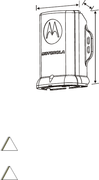
Dimensions
The dimensions of the transmitter are: width – 3.86" (98
mm), height – 4.77" (121 mm), depth – 1.8" (45.5 mm),
weight – 8.82 oz (250 g) maximum (see Figure 4).
1.8”
45.5 mm
3.86”
98 mm
4.77”
121mm
Figure 4
Dimensions of AMR RF Transmitter
Wall Mounting
!
C a u t i o n
The AMR transmitter should be enabled before
mounting. See the Enabling the Transmitter
section above.
!
C a u t i o n
Before installing the AMR transmitter, make
sure that the transmission frequency and
transmissions rate are appropriate. If not,
reprogram as described in Appendix C and the
AMR ToolBox User Guide.
Installation
12
The AMR transmitter can be installed on the wall using
screws. Before installing, verify that there is sufficient
space around the transmitter. Allow 6.3" (16 cm) from the
bottom of the transmitter for the antenna.
The AMR transmitter can be mounted on the wall using
screws, as shown in Figure 5 below.
1. Position the AMR transmitter as high as possible on
the wall.
2. Secure with two stainless steel self-tapping screws
(ST4.2, pan head) and two stainless steel flat washers,
inner diameter: 0.17", outer diameter 3/8", thickness
0.032" (not supplied).
Data
W
ires
A
ntenna
W
ire
Transmitter
Flat
Washers
Tapping
Screws
Figure 5
Installation of AMR Transmitter – Wall Screw Mount

Installation
13
3. Connect the transmitter wires to the meter wires, using
gel cups (not supplied) to seal the connection. Use a
3M™ recommended tool to squeeze the gel cup until
the connection is sealed.
- If the meter wires are floating, connect the two data
wires to the meter wires.
- If one of the meter wires is connected to the
ground/common (-), connect it to the black wire on the
transmitter and connect the green wire to the switch
(+).
The transmitter wires are 18" (45.7 cm) long. If this is
not adequate to reach the meter, add up to 100 ft (30
m) of AWG20 wire.
!
C a u t i o n
To ensure that moisture does not damage the
transmitter, gel cups must be used to seal the
connection between the data wires and the
meter.
!
C a u t i o n
Make sure that the antenna is pointing
downwards in as straight a line as possible. If
necessary, bend the antenna into a vertical
position.
Installation
14
Pit Installation
!
C a u t i o n
The AMR transmitter should be enabled before
installing. See the Enabling the Transmitter
section above.
!
C a u t i o n
Before installing the AMR transmitter, make
sure that the transmission frequency and
transmissions rate are appropriate. If not,
reprogram as described in Appendix C and the
AMR ToolBox User Guide.
The AMR transmitter can be installed in a meter pit with a
metal or plastic lid. Before installing, verify that the
available space is at least 10" (25.4 cm) deep and 4.7"
(12 cm) in diameter. The thickness of the lid can be
between .25" (6.3 mm) and 1" (2.54 cm).
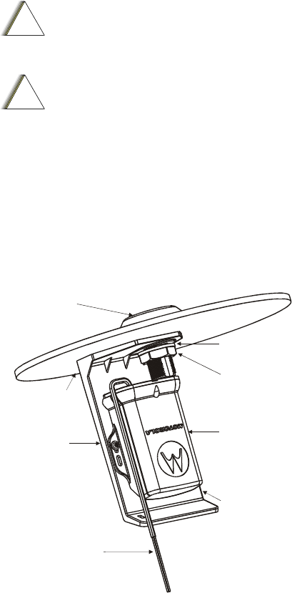
Data Wires
Transmitter
2 Ejot
M4x14 Screws
+ 2 SST
W
ashers
Pit Lid
Spring Washer
Top
Protective
Cover
Nut
Bracket
Figure 6
Pit Installation
Installation
15
1. Remove the lid from the pit.
2. Drill 1.1" or 1 1/8" hole in the flat portion of the lid.
(The flat portion should be at least 3.54 sq. in or 9 sq.
cm.) Remove burrs from the edges of the hole.
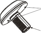
3. Spread any type of RTV sealant on the bottom of the
antenna cover.
Apply
sealant here
Hole for
Antenna
Figure 7
Antenna Cover
4. Insert the threaded bottom of the antenna cover
through the top of the hole in the lid, and through the
top hole of the bracket, aligning the flat edge of the
threading with the flat edge of the hole.
5. Fix the top of the bracket on the internal side of the lid
and secure it with the spring washer and nut
(supplied).
6. Tighten the nut with a wrench (not supplied) with a
torque of 40 ± 5 in-lb.
Installation
16
A
ntenna
Cover
Bracket
Pit Lid
Washer
Nut
W
ire Hole
Figure 8
Bracket Attached to Pit Lid
!
C a u t i o n
Do not exert torque of more than 40 ± 5 in-lb on
the nut or it may be damaged.
7. Invert the lid and bracket and place carefully on the
ground, resting the full weight on the top of the
antenna cover (with the Motorola symbol).
8. Insert the antenna (attached to the transmitter)
downwards through the antenna hole at the bottom of
antenna cover (see Figure 6) until the transmitter
housing meets the threaded base of the antenna cover.
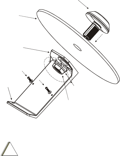
9. Secure the transmitter to the bracket with two Ejot
M4x14 stainless steel screws and two stainless steel
flat washers, inner diameter: 0.17", outer diameter
3/8", thickness 0.032" (supplied) as shown in Figure 9.
Installation
17
Data Wires
Transmitter
Ejot
M4x14 Screws
+ SST
Washers
Pit Lid
Spring Washer
Top Protective
Antenna Cover
Nut
Bracket
Figure 9
AMR Transmitter Mounted on Pit Lid
10. Thread the transmitter input wires through the small
wire hole at the base of the bracket (see Figure 8) OR
attach transmitter wires to side of bracket, threading a
strip (not supplied) through the small wire hole at the
base of the bracket.
11. Connect the transmitter wires to the meter wires, using
gel cups (not supplied) to seal the connection. Use a
3M™ recommended tool to squeeze the gel cup until
the connection is sealed.
- If the meter wires are floating, connect the two data
wires to the meter wires.
- If one of the meter wires is connected to the
ground/common (-), connect it to the black wire on the
transmitter and connect the green wire to the switch
(+).
The transmitter wires are 18" (45.7 cm) long. If this is
not adequate to reach the meter, add up to 100 ft (30
m) of AWG20 wire.

Installation
18
!
C a u t i o n
To ensure that moisture does not damage the
transmitter, gel cups must be used to seal the
connection between the data wires and the
meter.
12. Replace the lid on the pit with the antenna cover facing
up.
!
C a u t i o n
The plastic bracket can withstand the weight of
the lid (up to 330lb/ 150 kg). Care should be
taken not to exert more than this weight or else
the bracket might break.
Connections
Data Connection
Two data input wires from the transmitter are connected to
the meter, one to each side of the switch.
Programming Connection
The two data wires of the transmitter can be connected to
the programmer unit for enabling, programming and
testing the transmitter using the AMR ToolBox. Connect
the black wire on the programming cable to the black wire
on the transmitter and the green wire to the green.
19
THE AMR RF TRANSMITTER
Overview
The AMR RF transmitter contains a UHF radio (450-
470MHz 12.5 KHz bandwidth) and a logic circuit interface
to a single pulse-type meter. The transmitter includes an
internal lithium battery.
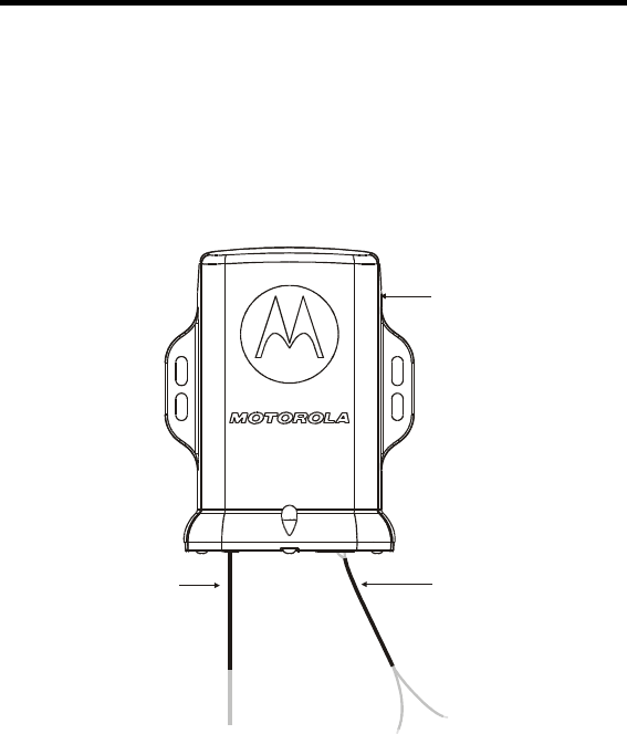
Data
W
ires
A
ntenna
W
ire
AMR RF
Transmitter
Figure 10
AMR RF Transmitter

The AMR RF Transmitter
20
Communication
The transmitter communicates via receiver/ repeater or
programmer units in two ways:
Meter data is sent via one-way UHF communication to a
receiver.
When the data input wires of the transmitter are connected
to a programmer unit which is connected to the AMR
ToolBox PC, programming commands are received from
the ToolBox and transmissions are sent to the air. See
Appendix C for details.
Connectors
The AMR transmitter has one internal connector for the
data input wires.
Internal Battery
The AMR RF transmitter is powered with an internal
lithium battery. The calculated battery life estimate is 13
years, based on 6 transmissions per day, zero repetitions,
in 70º F temperatures.
The battery can be replaced by performing a solder
operation on the terminal leads by authorized personnel in
lab conditions. See Appendix D below for instructions on
replacing the battery.
!
C a u t i o n
Once the transmitter has been enabled, it
cannot be disabled, unless the battery and
capacitor are detached. If an enabled AMR
transmitter is to be transported by air, the
transmitter housing must be opened and the
battery terminals and capacitor must be
unsoldered.
The AMR RF Transmitter
21
The transmitter sends a battery status signal as part of its
transmission. When a low battery indication appears, the
transmitter has enough calculated power for approximately
five months ( ± 3 months) of normal operation.
The AMR RF Transmitter
22

23
APPENDIX A: SPECIFICATIONS
Transmission
Frequency: UHF 450-470 MHz (field
configurable)
Channel Bandwidth: 12.5 KHz
Operation Mode: Transmit only
RF Power: 100mW ERP, maximum
120mW ERP
ID Globally unique serial number
Data Speed: 1200 bits per second
Transmission Rate: Either 1/week, 1/day, 4/day or
6/day (factory and field
configurable)
RF Cable: RG316
Power Source
Battery Type: Tadiran TL-4903 internal
lithium battery
Shelf Life: ~1-2% discharge per year
Replacement Method: Solder operation on terminal
leads
Capacitor: Tadiran HLC-1520A
Appendix A: Specifications
24
Interface to Pulse Type Meter
Interface Cable: 18" (45.7 cm) 2-wire AWG20
teflon conductor cable
with unterminated ends
Pulse: Dry contact, open/close to the
2-wire conductor cable
Counter Rollover: The counter embedded in the
RF Transmit unit will rollover
a counter value of 231 (or
approximately 2 billion)
counts.
Environmental
Operating Temperature: -22°F to +140°F
(-30°C to +60°C)
Storage Temperature: -40°F to +158°F
(-40°C to +70°C)
Installation: Indoor/outdoor/pit
Water Resistance: Submersible, IP 67
UL: UL60950
FCC: FCC parts 15 and 90
Form Factor
Housing: Injection molded plastic, UV
resistant, UL94 V1
Dimensions: 3.86" x 4.77" x 1.8"
(98x121x45.5mm)
Weight: 8.82 oz (250g ± 50g)
Appendix A: Specifications
25
Pit Installation Kit
Bracket Dimensions: 4.72"w x 9.8"h
(12cm x 25 cm)
Bracket Screw: 1" threaded screw,
spring washer, and nut
Bracket Strength: Withstands torque of
40 ± 5 in-lb
Antenna Cover Dimensions: 3.23" (82mm) diameter
Antenna Cover Impact
Resistance: Withstands 330lb (150 kg)
Specifications subject to change without notice.
Appendix A: Specifications
26

27
APPENDIX B: MODELS AND
ACCESSORIES
General
The chart below describes the models, options and
accessories available.
AMR Transmitter Models Model
AMR RF TRANSMITTER UHF
100MW 450-470MHZ 12.5KHZ
F4714A
AMR Transmitter Accessories Accessory
ADD: Pit Antenna Installation Kit FHN6584A
Miscellaneous Model/Option
AMR Programming Kit (includes
p
rogrammer unit, cables, AMR ToolBox
software, and magnet)
F4604A+
V345AK
Appendix B: Models and Accessories
28

29
APPENDIX C: THE AMR TOOLBOX
Programming the Transmitter
The AMR RF transmitter can be reprogrammed using the
AMR ToolBox. This is generally done during installation
or when changing the meter. Basic programming functions
include:
• Enabling the transmitter
• Testing the transmitter
• Forcing a transmission
• Changing the transmitter parameters
For more details on programming the transmitter, see
AMR ToolBox User Guide.
If the transmitter parameters are changed once it is
operational, the meter readings should be recorded, as
described in the Recording Counter Values/Readings
section of the Installation chapter, to ensure data collection
integrity.
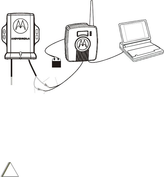
Connecting the Transmitter to the ToolBox
In order to reprogram, the transmitter is connected to a
programmer unit which is connected to a PC running the
AMR ToolBox, as shown in the figure below.
Appendix C: The AMR ToolBox
30
+-
Data Wires
PC with
ToolBox S/W
Transmitter Programmer
9V/12V DC
RS232
Green
Black
Figure 11
Programming Equipment Setup
1. If the AMR RF transmitter is already connected to the
meter, cut the data input wires (as close to the end as
possible) and expose the tips.
!
C a u t i o n
If the wires are connected incorrectly, the equipment
may be damaged.
2. Connect the programmer unit to a DC power source.
For a standard 9V DC battery, use the short power
cable supplied with the Programming Kit. For a
12VDC battery, insert the protection board
(FCN6538A) into the DC power connector on the back
of the programmer unit and then attach the 7 ft power
cable (supplied with the Programming Kit).
3. Connect the programmer unit to the ToolBox PC,
using the RS232 cable and RS232 connector
(FTN6597A) supplied with the Programming Kit.
4. Power up the programmer unit by inserting the On/Off
TB supplied with the Programming Kit into the GND
connector.

Appendix C: The AMR ToolBox
31
5. Power up the PC.
6. Start up the AMR ToolBox.
7. Using crocodile clips, attach the green data input wire
on the transmitter to the green wire on the programmer
unit programming cable, and the black data input wire
on the transmitter to the black wire on the
programming cable.
After programming, be sure to remove the On/Off TB to
power off the programmer unit in order to save battery
power.
Transmitter Parameters
The following parameters can be modified using the AMR
ToolBox Configuration tools:
• Tx Frequency (450-470MHz), if the frequency is not
suitable or if there is interference. Do not change the
frequency without FCC approval. This parameter is
changed in the Transmitter Radio Configuration tool.
• Transmissions Rate (6/day, 4/day, 1/day, or 1/week),
as required. This parameter is changed in the AMR
Parameters tab of the Transmitter Configuration tool.
• Number of Repetitions (0-3), generally when there are
reception problems. This parameter is changed in the
AMR Parameters tab of the Transmitter Configuration
tool.
!
C a u t i o n
Increasing the number of repetitions significantly
reduces the life of the battery. This step should be
taken only in extreme cases and with the approval of
authorized personnel.
To change a transmitter parameter, go to the relevant tab,
change the value and save the change. For more
information on transmitter parameters, see the AMR
ToolBox User Guide.

Appendix C: The AMR ToolBox
32
If the transmitter parameters are changed once it is
operational, the meter readings should be recorded, as
described in the Recording Counter Values/Readings
section of the Installation chapter above, to ensure data
collection integrity.
Enabling the Transmitter
To enable the transmitter,
1. Click on the Enable Transmitter button in the
Transmitter Status tool.
!
C a u t i o n
Once the AMR transmitter is enabled, it cannot be
disabled. Do not enable the AMR transmitter if it is
to be transported by air.
2. Select the Transmitter Status tool.
3. Click on the Enable Transmitter button.
4. The results (either Succeeded or Failed) will appear on
the screen.
5. To check the status, click on the Upload button.
6. The status (either Enabled or Disabled) will appear on
the screen.
Testing the Transmitter
To test if the transmitter is operational using the AMR
ToolBox,
1. Select the Transmitter Hardware Test tool.
2. Click on the Comm Test tab.
3. Click on the Start button.
4. Verify the OK/Fail status in the Test Result on the
screen.
Appendix C: The AMR ToolBox
33
Forcing a Transmission
Forcing a transmission is done when testing the transmitter
and when recording the meter counter in the Host. To
force a transmission,
1. Select the Transmitter Hardware Test tool.
2. Click on the Comm Test tab.
3. Click on the Force button.
The transmission information includes: Unit ID, meter
counter value, battery status and the Transmissions Rate
setting. This information can be read using the AMR
ToolBox Comm Monitor tool on a programmer unit,
concentrator Viewer or at the Host.
Appendix C: The AMR ToolBox
34
35
APPENDIX D: BATTERY
REPLACEMENT
Replacing the Battery
If it is necessary to replace the internal lithium battery,
follow the procedure below:
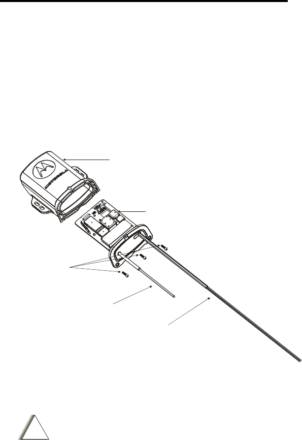
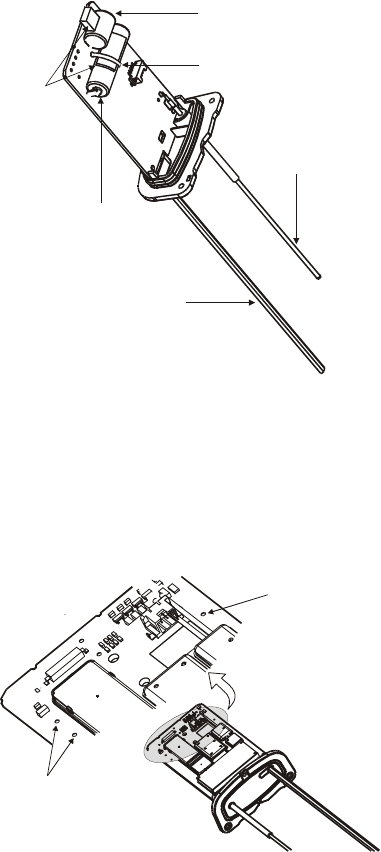
1. Using a screwdriver, unscrew the three screws at the
bottom of the transmitter.
2. Pull the housing away from the base to expose the
printed circuit board.
Housing
Screws
Antenna
Wire
Data Wires
Data Input
Wire
Connector
Figure 12
AMR RF Transmitter- Exploded View
!
C a u t i o n
When opening, closing and soldering the transmitter
unit, take care not to damage the soldered
connection of the antenna wire to the circuit board.
Appendix D: Battery Replacement
36
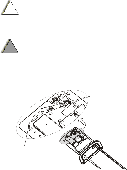
The battery and capacitor are soldered onto the printed
circuit board, as shown below.
Battery
Capacitor
A
ntenna
Wire
Data Wires
Plastic Strip
Protective
Pads
Figure 13
Battery and Capacitor on Transmitter Circuit Board
3. Cut the plastic strip tied around the battery.
4. Using a soldering iron, heat the legs on the battery
connection until they become soft.
Battery
Terminal
Battery
Terminals
Figure 14
Battery Terminals- Top View for Soldering
Appendix D: Battery Replacement
37
!
C a u t i o n
When soldering battery terminals, use caution to
take care not to damage any other components on
the circuit board.
5. Remove the old battery from the circuit board.
!
W A R N I N G
!
Always replace the battery with the type specified in
this document to avoid risk of explosion.
Dispose of used batteries according to manufacturer
instructions and local environmental laws.
6. Using a soldering iron, heat the legs on the capacitor
connection until they become soft.
Capacitor
Terminal
Capacitor
Terminals
Figure 15
Capacitor Terminals- Top View for Soldering
7. Remove the capacitor from the circuit board.
8. Peel the liner off a new protective pad (part number
7588383V65) and adhere it to the side of a new battery,
as shown in Figure 13 above.
9. Place the new battery on the circuit board and secure
with a new plastic strip, as shown in Figure 13 above.
10. Solder the battery leg connections from the top of the
circuit board, using caution to avoid damaging other
components on the board.
11. Place a new capacitor on the circuit board, as shown in
Figure 13 above.
Appendix D: Battery Replacement
38
12. Solder the capacitor leg connections from the top of
the circuit board, using caution to avoid damaging
other components on the board.
13. Check that the data input wires are properly connected
to the connector and that the antenna is properly
soldered.
14. Peel the liner off a new protective pad (part number
7588383V66) and adhere it to the side of the new
capacitor, parallel to circuit board, as shown in Figure
13 above.
15. Carefully slide the circuit board back into the housing,
taking care not to disturb the antenna connection to the
board.
16. With a screwdriver, replace the three screws at the
bottom of the transmitter, applying torque of 6 in-lb.
Note: If it is convenient, the data input wire can be
disconnected from the internal connector before soldering
and reconnected after the battery and capacitor are
replaced.

MOTOROLA and the Stylized M Logo are registered in the U.S.
Patent and Trademark Office. All other product or service names
are the property of their respective owners.
Copyright © 2004 Motorola All Rights Reserved
6802973C65-O
@6802973C65@
July 2004

Please retain for future use
Copyright © 2004 Motorola
All Rights Reserved
6802974C60-O
@6802974C60@
Product Safety and RF Exposure for the AMR RF
Transmitter
BEFORE USING THIS RF TRANSMITTER, READ THIS BOOKLET WHICH CON-
TAINS IMPORTANT OPERATING INSTRUCTIONS FOR SAFE USAGE AND RF
ENERGY AWARENESS AND CONTROL INFORMATION FOR COMPLIANCE
WITH RF ENERGY EXPOSURE LIMITS IN APPLICABLE NATIONAL AND
INTERNATIONAL STANDARDS.
The information provided in this document supersedes information contained in user
guides published for this product prior to July 2004.
The AMR RF Transmitter is designed for fixed locations.
Compliance with RF Energy Exposure Standards
Notice: This RF transmitter is intended for use in uncontrolled environments.
Federal Communication Commission Regulations
The FCC established limits for safe exposure to radio frequency (RF) emissions from
two-way radios. The FCC requires manufacturers to demonstrate compliance with
RF exposure limits before two-way radios can be marketed in the U.S.
Your AMR RF Transmitter is designed and tested to comply with a number of nation-
al and international standards and guidelines (listed below) regarding human expo-
sure to radio frequency electromagnetic energy. This transmitter complies with the
IEEE (FCC) and ICNIRP exposure limits for uncontrolled RF exposure environ-
ments. In terms of measuring RF energy for compliance with the FCC exposure
guidelines, your AMR RF Transmitter radiates measurable RF energy only while it is
transmitting, not when it is in standby mode.
Your AMR RF Transmitter complies with the following RF energy
exposure standards and guidelines:
• United States Federal Communications Commission, Code of Federal Regula-
tions; 47CFR part 2 sub-part J
• American National Standards Institute (ANSI) / Institute of Electrical and Elec-
tronic Engineers (IEEE) C95. 1-1992
• Institute of Electrical and Electronic Engineers (IEEE) C95.1-1999 Edition
• International Commission on Non-Ionizing Radiation Protection (ICNIRP) 1998
• Ministry of Health (Canada) Safety Code 6. Limits of Human Exposure to
Radio frequency Electromagnetic Fields in the Frequency Range from 3 kHz to
300 GHz, 1999
• Australian Communications Authority Radio communications (Electromagnetic
Radiation - Human Exposure) Standard 2003
• ANATEL, Brazil Regulatory Authority, Resolution No. 303 of July 2, 2002 "Reg-
ulation of the limitation of exposure to electrical, magnetic, and electromagnetic
fields in the radio frequency range between 9KHz and 300 GHz" and “Attach-
ment to resolution # 303 from July 2, 2002”
Compliance and Control Guidelines and Operating Instructions for
the AMR RF Transmitter
To control your exposure and ensure compliance with the uncontrolled environment
exposure limits, always adhere to the following procedures.
• Use only Motorola approved supplied or replacement accessories. Use of non-
Motorola-approved accessories may exceed FCC RF exposure guidelines.
• The end-user would be provided with appropriate installation instructions for
satisfying RF exposure compliance.
It is recommended that the transmitter be installed such that the antenna and the
transmitter are kept 7.8 inches (20 cm) from passersby when transmitting. Keeping
the transmitter at a proper distance is important because RF exposures decrease
with distance from the antenna.
For additional information on RF exposure awareness information, visit the following
Motorola website: www.mot.com/rfhealth.
AMR RF
TRANSMITTER
ab
transmittersafety.fm Page 1 Tuesday, September 21, 2004 6:10 PM

Electromagnetic Interference/Compatibility
Note: Nearly every electronic device is susceptible to electromagnetic interference
(EMI) if inadequately shielded, designed, or otherwise configured for electromagnet-
ic compatibility.
Medical Devices
Pacemakers
The Advanced Medical Technology Association (AdvaMed) recommends that a min-
imum separation of 6 inches (15 centimeters) be maintained between the
AMR RF Transmitter and a pacemaker. These recommendations are consistent with
those of the U.S. Food and Drug Administration.
Persons with pacemakers should:
• ALWAYS keep the RF Transmitter more than 6 inches (15 centimeters) from
their pacemaker when the RF Transmitter is enabled.
• Increase the distance from the enabled RF Transmitter immediately if you have
any reason to suspect that interference is taking place.
Hearing Aids
Some digital wireless radios may interfere with some hearing aids. In the event of
such interference, you may want to consult your hearing aid manufacturer to discuss
alternatives.
Other Medical Devices
If you use any other personal medical device, consult the manufacturer of your
device to determine if it is adequately shielded from RF energy. Your physician may
be able to assist you in obtaining this information.
Operational Warnings
Potentially Explosive Atmospheres
Do not take an enabled RF Transmitter into any area with a poten-
tially explosive atmosphere, unless it is especially qualified for use
in such areas as "Intrinsically Safe" (for example, Factory Mutual,
CSA, UL, or CENELEC).
Sparks in a potentially explosive atmosphere can cause an explo-
sion or fire resulting in bodily injury or even death. The areas with
potentially explosive atmospheres referred to above include fuel-
ing areas such as below decks on boats, fuel or chemical transfer
or storage facilities, areas where the air contains chemicals or par-
ticles, such as grain, dust or metal powders. Areas with potentially
explosive atmospheres are often but not always posted.
Blasting Caps and Blasting Areas
To avoid possible interference with blasting operations, do not take
an enabled RF Transmitter near electrical blasting caps or in a
blasting area. Obey all signs and instructions.
Operational Cautions
Battery
There is a risk of explosion if this battery is replaced with an incor-
rect type. Dispose of used batteries according to instructions.
transmittersafety.fm Page 2 Tuesday, September 21, 2004 6:10 PM