Motorola Solutions 89FT4873 PMUE2384A-PORTABLE 2-WAY RADIO User Manual Text
Motorola Solutions, Inc. PMUE2384A-PORTABLE 2-WAY RADIO Text
USERS MANUAL
PRODUCT SAFETY AND RF EXPOSURE COMPLIANCE
ATTENTION!
This radio is restricted to occupational use only to satisfy FCC RF energy exposure require-
ments. Before using this product, read the RF energy awareness information and operating instruc-
tions in the Product Safety and RF Exposure booklet enclosed with your radio (Motorola
Publication part number 6804110J47) to ensure compliance with RF energy exposure limits.
For a list of Motorola-approved antennas, batteries, and other accessories, visit the following web
site which lists approved accessories: http://ap.cgiss.motorola.com/AAD/index.html.
© 2004 by Motorola, Inc.
Motorola Technology Sdn. Bhd. (Co. No. 455657-H)
Plot 2, Bayan Lepas Technoplex Industrial Park,
Mukim 12, S.W.D.,11900 Penang, Malaysia
Printed in Malaysia. 11/04. All Rights Reserved.
Before using this product, read the operating instructions for safe usage contained in the
Product Safety and RF Exposure booklet enclosed with your radio.
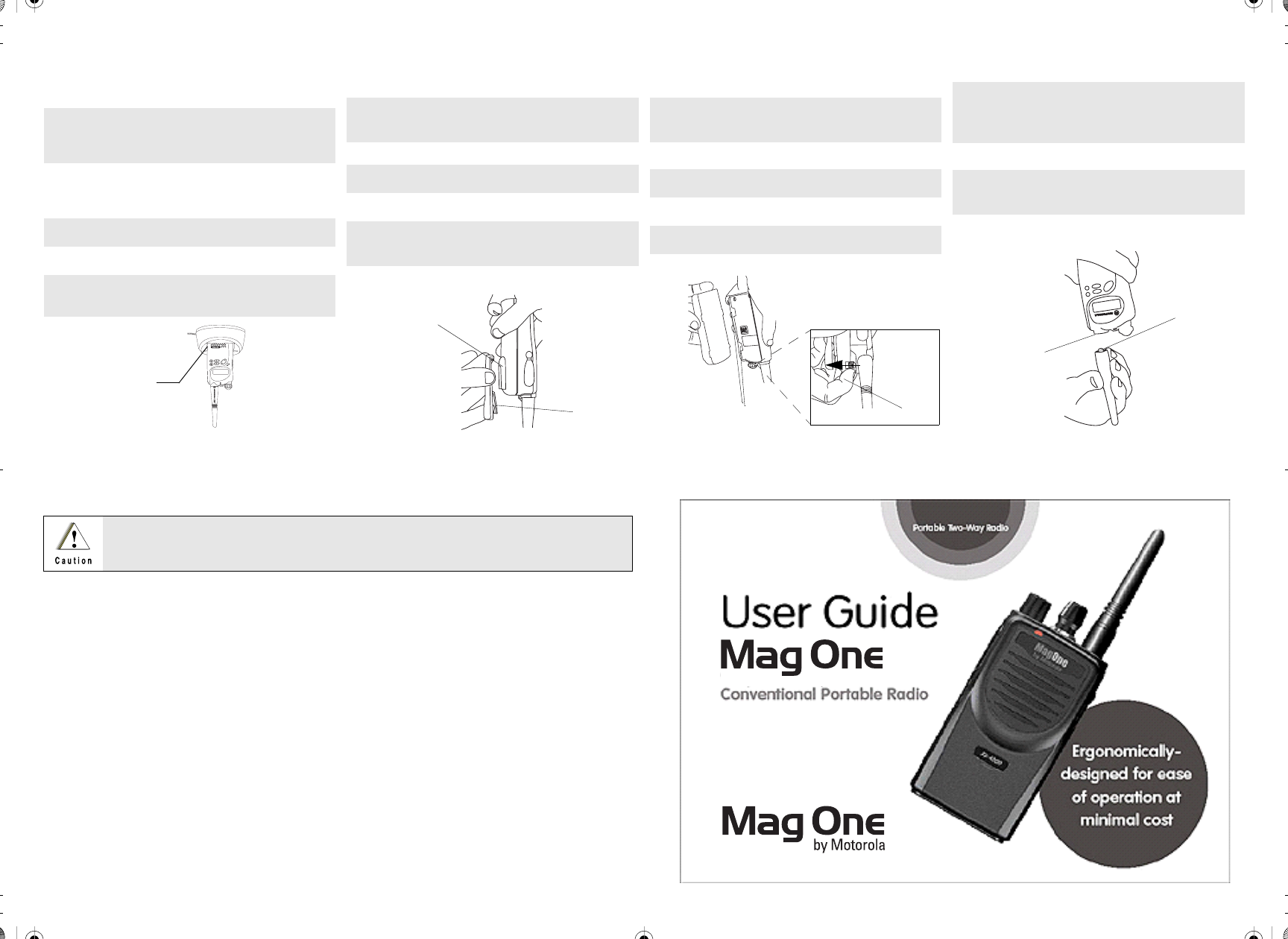
Attaching and Removing the Antenna
To Remove Antenna
To Attach Antenna
1. Turn the antenna in a counter-clockwise
direction until it disengages from the radio.
1. Fasten the antenna to the radio by placing
the threaded end of the antenna into the
Antenna Connector.
2. Rotate the antenna clockwise until tight.
Antenna Connector
Threaded End
of Antenna
Attaching and Removing the Battery
To Remove Battery
To Attach Battery
1. Slide the battery clasp away from the radio.
2. Slide the battery downwards.
3. Pull the battery away from the radio.
1. Fit the battery slots with the grooves on the
radio.
2. Slide the battery upwards until a click is
heard.
Battery
Clasp Grooves
Attaching and Removing the Belt Clip
To Remove Belt Clip
To Attach Belt Clip
1. Insert the end of a key between the release
tab and the back surface of the radio.
2. Lift the release tab.
3. Slide the belt clip upwards.
1. Align mounting rails of the radio with the
grooves of the belt clip.
2. Slide the belt clip downwards until it clicks
into place.
Release Tab
Mounting Grooves
Charging your Radio
1. Turn off your radio and the A/C power sup-
ply to your charger (if they are turned on).
2. Place your radio in the charger pocket.
3. Turn on the charger’s A/C power supply.
4. Charge your radio until the charger’s LED
shows a steady green light (around 2 hours
later).
5. Turn off the charger’s A/C power supply,
and remove the radio from the charger
pocket.
6. Turn on your radio; you should see all 3
bars of the Battery Level Indicator illumi-
nated.
Charger
Pocket
*6804113J11*
6815549H01-O
Text.fm Page 1 Tuesday, December 28, 2004 12:21 PM
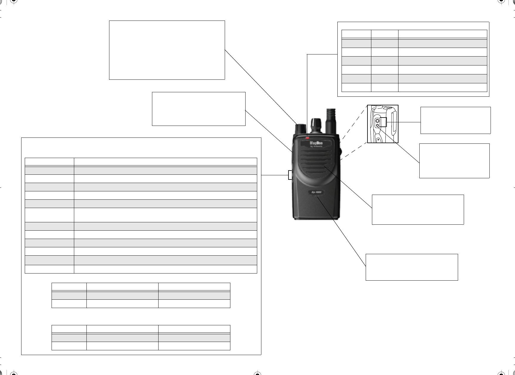
LED Indicators
LED Colour State Indication
Red Illuminated Radio is transmitting.
Blinking Battery voltage is low.
Green Illuminated Radio is receiving with PL/DPL disabled.
Blinking Radio is in active scanning mode.
Orange Illuminated Radio is receiving with PL/DPL enabled.
Blinking An error has occured.
On/Off and Volume Knob
• If the radio is off, turn this knob clockwise to turn
the radio on.
• If the radio is on, turn this knob counter-clockwise
to turn the radio off.
• Turn this knob clockwise to increase the volume.
• Turn this knob counter-clockwise to decrease the
volume.
Push-to-Talk (PTT) button
• Press and speak to microphone to send
message.
• Release and listen to receive messages.
Programmable Buttons
• The following functions are assigned as short press (press and release) or long press (press and hold for 1
second).
• The default functions assigned to your radio are described in the table below.
• If your dealer has re-programmed your radio’s programmable buttons, please enter the new functions in the
table below.
Button Function
High/Low Power Selects desired power level to High or Low.
Volume Set Allows you to check the audio and alert tone volume level.
Monitor Allows you to monitor the current channel for activity; disables squelch.
Sticky Monitor The radio monitors continually until you press this button again.
Scan Starts or stops channel scan.
Nuisance Channel
Delete
Removes unwanted channel(s) temporarily from scan list during scan.
Repeater/Talkaround Toggles your radio between functioning in Repeater mode or Talkaround mode.
PL/DPL Enables or disables your radio from requiring matching PL/DPL to receive messages.
Button Lock Locks or unlocks all buttons except PTT and On/Off/Volume Knob.
Battery Save Mode Toggles your radio between functioning with Battery Saver ON or Battery Saver OFF.
Squelch Selects desired squelch level: Normal or Tight.
Unassigned No function is programmed to this button.
Press Type Programmable Button 1 Programmable Button 2
Short Press Monitor Scan
Long Press Sticky Monitor Nuisance Channel Delete
Press Type Programmable Button 1 Programmable Button 2
Short Press
Long Press
Speaker
• You will hear received messages through
the speaker.
Microphone
• Speak into the microphone when send-
ing message.
Accessory Connector
• Used to connect compatible
accessories to your radio.
Programming Port
• Lower port of radio.
• Use by your dealer to program
your radio.
Text.fm Page 2 Tuesday, December 28, 2004 12:21 PM